ENGINE PERFORMANCE
2.5L
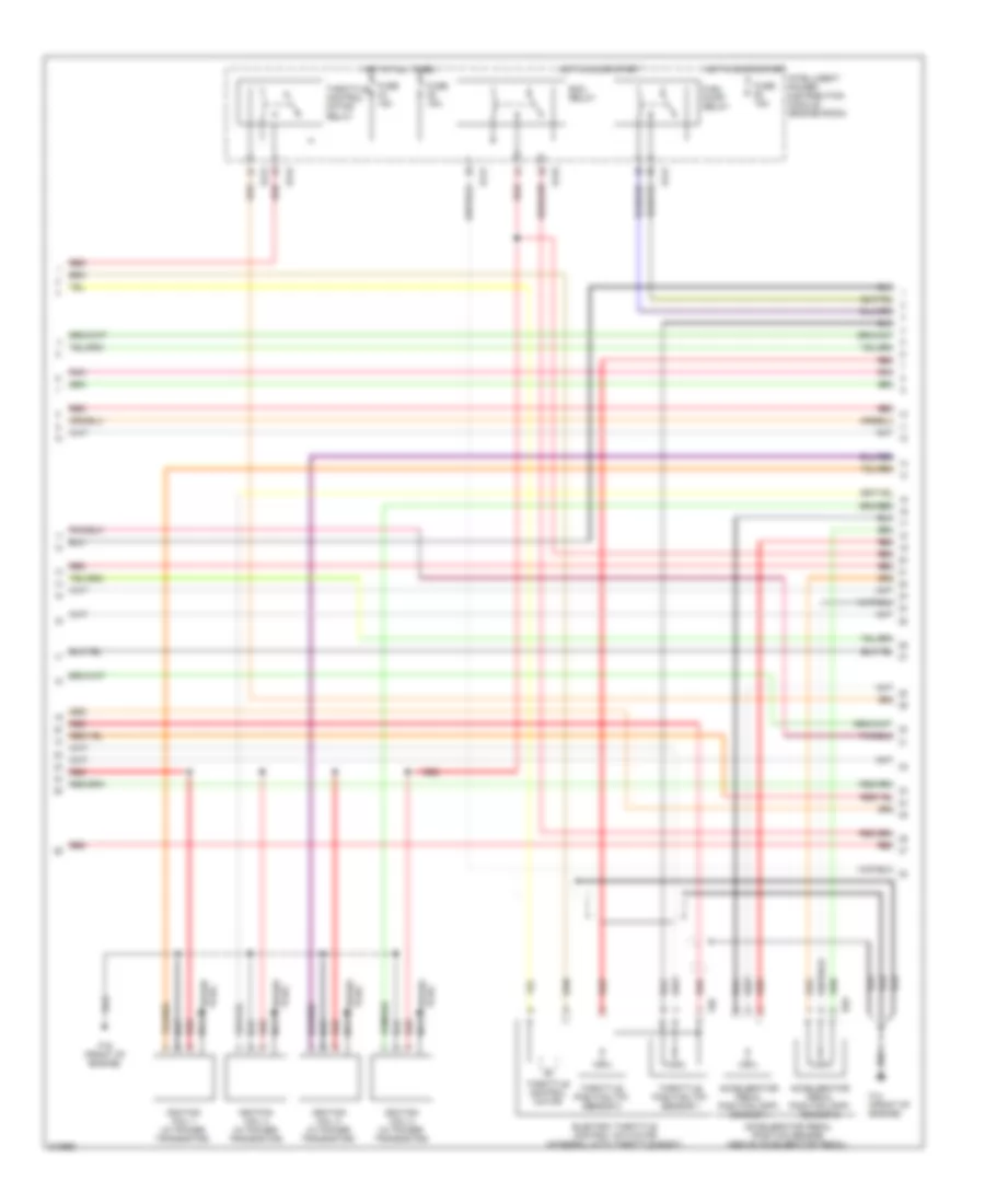
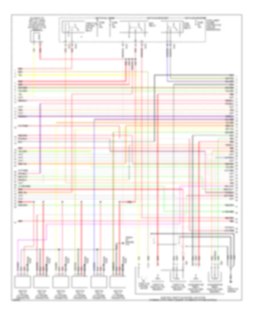
2.5L, Engine Performance Wiring Diagram (1 of 4) for Nissan Altima SE-R 2006
 https://portal-diagnostov.com/license.html
Automotive Electricians Portal FZCO
Automotive Electricians Portal FZCO
https://portal-diagnostov.com/license.html
https://portal-diagnostov.com/license.html
Automotive Electricians Portal FZCO
Automotive Electricians Portal FZCO
List of elements for 2.5L, Engine Performance Wiring Diagram (1 of 4) for Nissan Altima SE-R 2006:
- (front of engine) f16
- (on front of engine) f14
- 15p
- Af-h1
- Af-un1
- Af-vm1
- Afip1
- Avcc
- Avcc2
- Combination meter
- Computer data lines system
- Condenser 2 (right side of engine compt)
- Crankshaft position sensor (pos) (on right rear of cylinder block, below starter motor)
- Engine control module (behind glove box)
- Evap
- Evap canister purge volume control solenoid valve (on intake manifold, near throttle body)
- F14 (on front of engine)
- Ftrps
- Fuel injector
- Fuse 10a
- Fuse block (j/b) (behind left side of dash)
- Gnd
- Hot in on or start
- Inj 1
- Inj 2
- Inj 3
- Inj 4
- Ivc
- Knk1
- Knock sensor (lower right side of cylinder block)
- Malfunction indicator lamp
- Motor1
- Motor2
- Neutral
- O2hrr
- Park/ neutral position switch (left rear of transaxle)
- Pdpres
- Phase
- Pnk
- Pnk (or red)
- Pos
- Ps pres
- Qa+
- Red
- Refrigerant pressure sensor (right front of engine compt, near radiator neck)
- Tps1
- Unified meter control unit
- V mot
- Vias
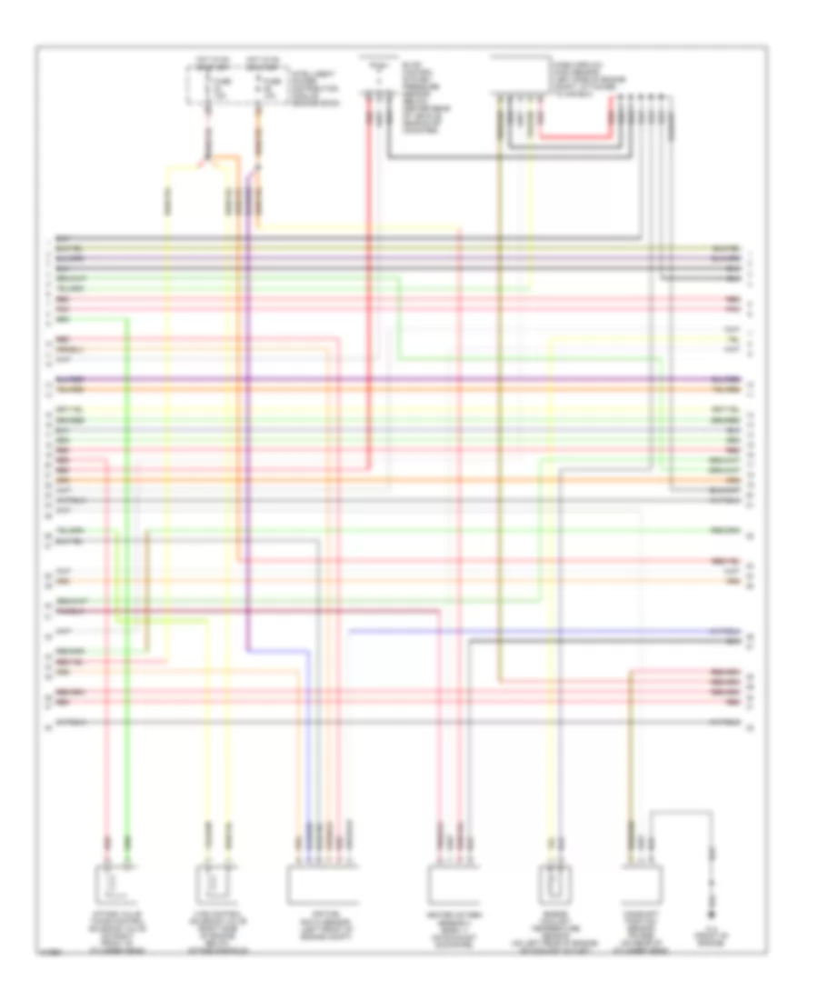
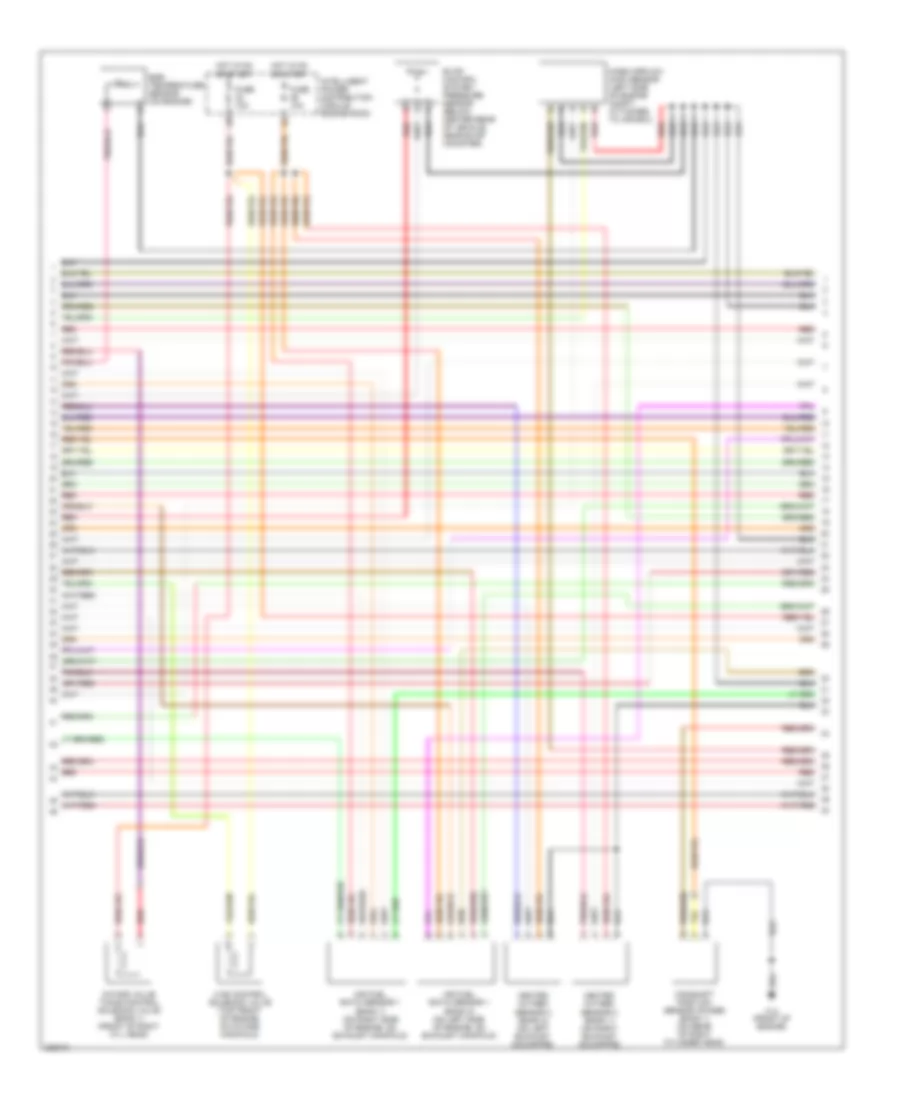
2.5L, Engine Performance Wiring Diagram (2 of 4) for Nissan Altima SE-R 2006
 https://portal-diagnostov.com/license.html
Automotive Electricians Portal FZCO
Automotive Electricians Portal FZCO
https://portal-diagnostov.com/license.html
https://portal-diagnostov.com/license.html
Automotive Electricians Portal FZCO
Automotive Electricians Portal FZCOList of elements for 2.5L, Engine Performance Wiring Diagram (2 of 4) for Nissan Altima SE-R 2006:
- Accelerator pedal position (app) sensor 1
- Accelerator pedal position (app) sensor 2
- Accelerator pedal position sensor (above accelerator pedal)
- E121
- E122
- E124
- E40
- Ecm relay
- Electric throttle control actuator (integral with throttle body)
- F14 (front of engine)
- F16 (front of engine)
- F50
- Fuel pump relay
- Fuse 15a
- Hot at all times
- Hot in on or start
- Ignition coil 1 (w/ power transistor)
- Ignition coil 2 (w/ power transistor)
- Ignition coil 3 (w/ power transistor)
- Ignition coil 4 (w/ power transistor)
- Intelligent power distribution module (engine room)
- Nca
- Plug spark
- Pnk
- Red
- Spark plug
- Throttle control motor
- Throttle control motor relay
- Throttle position (tp) sensor 1
- Throttle position (tp) sensor 2
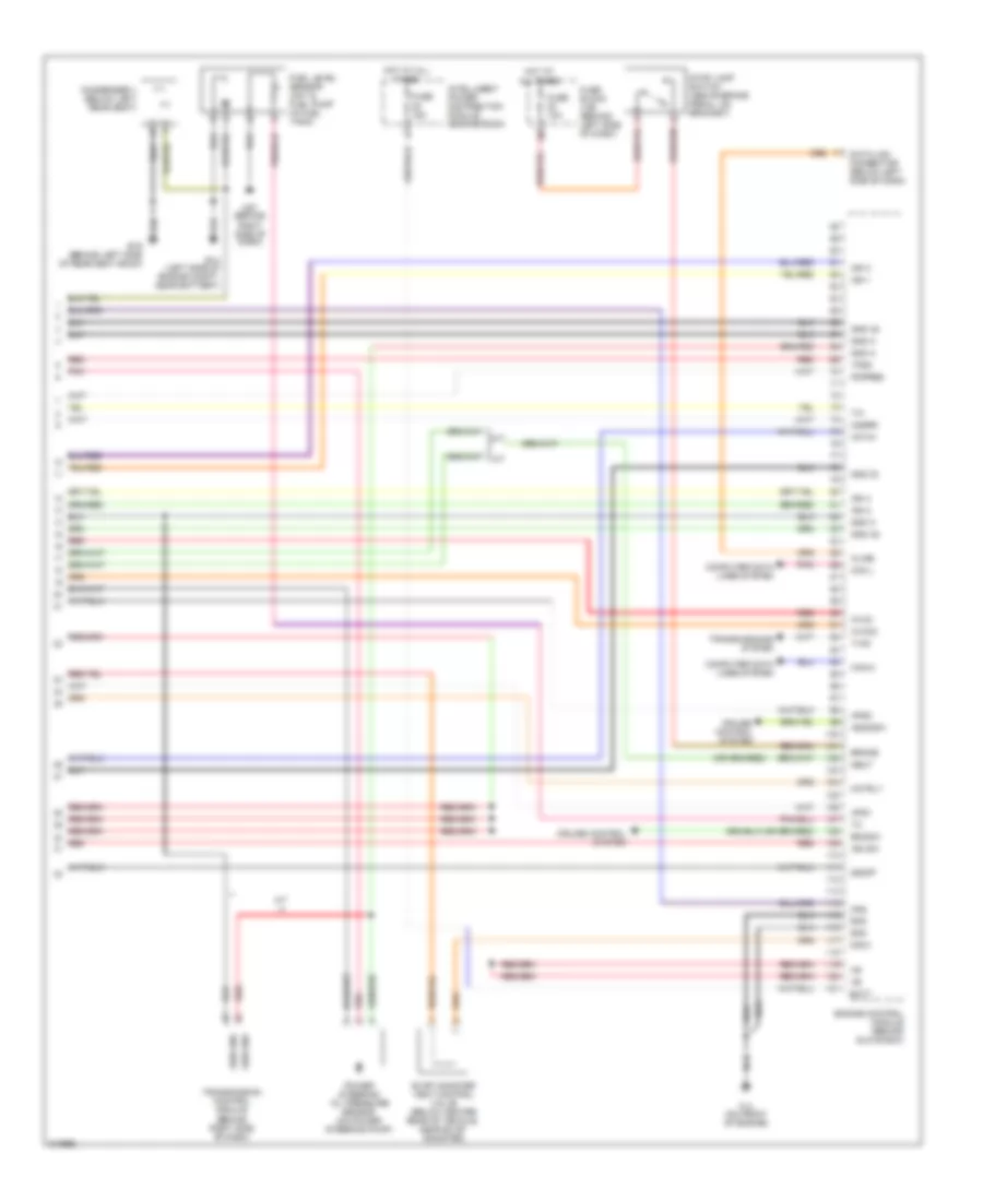
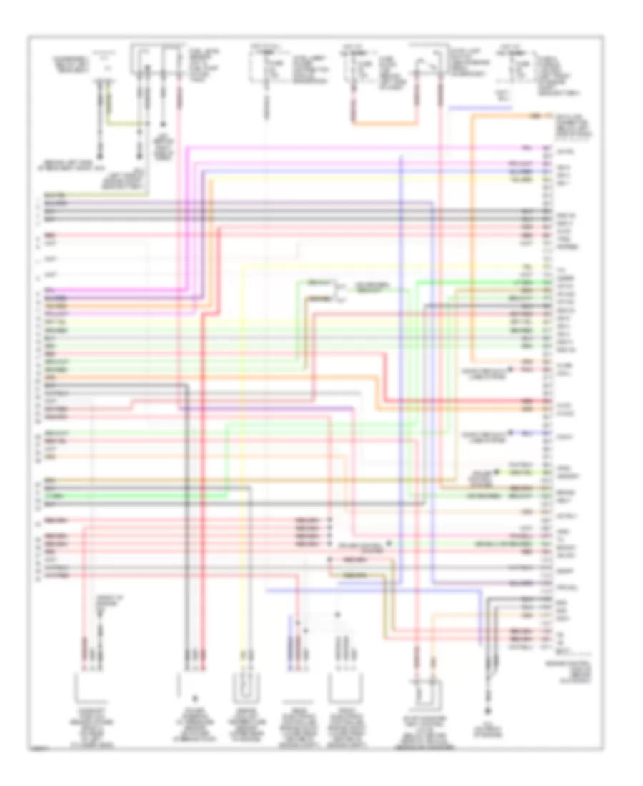
2.5L, Engine Performance Wiring Diagram (3 of 4) for Nissan Altima SE-R 2006
 https://portal-diagnostov.com/license.html
Automotive Electricians Portal FZCO
Automotive Electricians Portal FZCO
https://portal-diagnostov.com/license.html
https://portal-diagnostov.com/license.html
Automotive Electricians Portal FZCO
Automotive Electricians Portal FZCOList of elements for 2.5L, Engine Performance Wiring Diagram (3 of 4) for Nissan Altima SE-R 2006:
- Air fuel ratio sensor (left front of engine compt)
- Camshaft position sensor (phase) (on rear of cylinder head)
- Engine coolant temperature sensor (on left rear of engine, on coolant outlet)
- Evap control system pressure sensor (below center rear of vehicle, near evap canister)
- F14 (front of engine)
- Fuse 10a
- Heated oxygen sensor 2 (bank 1) (on exhaust downpipe)
- Hot in on or start
- Intake valve timing control solenoid valve (on right front of cylinder head)
- Intelligent power distribution module (engine room)
- Mass airflow (maf) sensor (left side of engine compt, attached to air box)
- Pnk
- Red
- Vias control solenoid valve (right side of engine, below intake manifold)
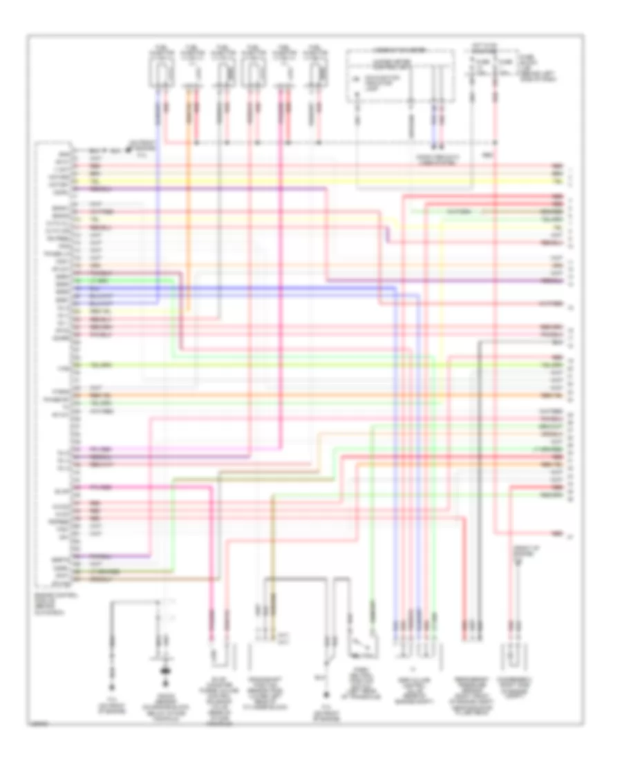
2.5L, Engine Performance Wiring Diagram (4 of 4) for Nissan Altima SE-R 2006
 https://portal-diagnostov.com/license.html
Automotive Electricians Portal FZCO
Automotive Electricians Portal FZCO
https://portal-diagnostov.com/license.html
https://portal-diagnostov.com/license.html
Automotive Electricians Portal FZCO
Automotive Electricians Portal FZCOList of elements for 2.5L, Engine Performance Wiring Diagram (4 of 4) for Nissan Altima SE-R 2006:
- A/f-ia1
- A/t
- Aps1
- Aps2
- Ascdsw
- Avcc
- Avcc2
- B19 (behind left side of rear seat back)
- Batt
- Bncsw
- Brake
- Can l
- Can-h
- Cdcv
- Computer data lines system
- Condenser 1 (below left rear seat)
- Cruise control system
- Data link connector (below left side of dash)
- E14 (left side of engine compt, near battery)
- Engine control module (behind glove box)
- Evap canister vent control valve (below center rear of vehicle, near evap canister)
- F14 (on front of engine)
- Fpr
- Fuel level sensor unit & fuel pump (in fuel tank)
- Fuse 10a
- Fuse 15a
- Fuse block (j/b) (behind left side of dash)
- Gnd
- Gnd 02
- Gnd a
- Gnd a2
- Hot at all times
- Ign 1
- Ign 2
- Ign 3
- Ign 4
- Ign sw
- Intelligent power distribution module (engine room)
- Kline
- M57 (behind right side of dash)
- Motrly
- Neut
- O2srr
- Pdpres
- Pnk
- Power steering oil pressure sensor (on power steering pump)
- Red
- Sen gnd
- Ssoff
- Stop lamp switch (above brake pedal, on bracket)
- Tps2
- Transmission control module (behind right side of dash)
- Transmissions system
- Tv00
3.5L
3.5L, Engine Performance Wiring Diagram (1 of 4) for Nissan Altima SE-R 2006
 https://portal-diagnostov.com/license.html
Automotive Electricians Portal FZCO
Automotive Electricians Portal FZCO
https://portal-diagnostov.com/license.html
https://portal-diagnostov.com/license.html
Automotive Electricians Portal FZCO
Automotive Electricians Portal FZCOList of elements for 3.5L, Engine Performance Wiring Diagram (1 of 4) for Nissan Altima SE-R 2006:
- (a/t)
- (front of engine) f16
- (m/t)
- (on front of engine)
- 15p
- Af-h1
- Af-h2
- Af-un1
- Af-vm1
- Af-vm2
- Afip1
- Avcc
- Avcc2
- Combination meter
- Computer data lines system
- Condenser 2 (right side of engine compt)
- Crankshaft position sensor (pos) (lower left rear of cylinder block)
- Cvtc cil
- Cvtc cir
- Egr volume control valve (rear of engine compt)
- Egr1
- Egr2
- Egr3
- Egr4
- Egrts
- Engine control module (behind glove box)
- Enmn1
- Enmn2
- Evap
- Evap canister purge volume control solenoid valve (rear of intake manifold)
- F14
- F14 (on front of engine)
- Ftrps
- Fuel injector
- Fuse 10a
- Fuse block (j/b) (behind left side of dash)
- Gnd
- Hot in on or start
- Inj 1
- Inj 2
- Inj 3
- Inj 4
- Inj 5
- Inj 6
- Knk1
- Knock sensor (on engine block, below intake manifold)
- Malfunction indicator lamp
- Motor1
- Motor2
- Nca
- Neutral
- O2hrl
- O2hrr
- O2srl
- Park/ neutral position switch (left rear of transaxle)
- Pdpres
- Phase lh
- Phase rh
- Pnk
- Pos
- Ps pres
- Qa+
- Red
- Refrigerant pressure sensor (right front of engine compt, near radiator filler neck)
- Tps1
- Unified meter control unit
- V mot
- Vias
3.5L, Engine Performance Wiring Diagram (2 of 4) for Nissan Altima SE-R 2006
 https://portal-diagnostov.com/license.html
Automotive Electricians Portal FZCO
Automotive Electricians Portal FZCO
https://portal-diagnostov.com/license.html
https://portal-diagnostov.com/license.html
Automotive Electricians Portal FZCO
Automotive Electricians Portal FZCOList of elements for 3.5L, Engine Performance Wiring Diagram (2 of 4) for Nissan Altima SE-R 2006:
- (front of engine) f16
- (on front of left cyl head) intake valve timing control solenoid valve (bank 2)
- Accelerator pedal position (app) sensor 1
- Accelerator pedal position (app) sensor 2
- E121
- E122
- E124
- E40
- Ecm relay
- Electric throttle control actuator (integral with throttle body, on rear of intake manifold)
- F14 (front of engine)
- F50
- Fuel pump relay
- Fuse 15a
- Hot at all times
- Hot in on or start
- Ignition coil 1 (w/ power transistor)
- Ignition coil 2 (w/ power transistor)
- Ignition coil 3 (w/ power transistor)
- Ignition coil 4 (w/ power transistor)
- Ignition coil 5 (w/ power transistor)
- Ignition coil 6 (w/ power transistor)
- Intelligent power distribution module engine room
- Nca
- Plug spark
- Red
- Spark plug
- Throttle control motor
- Throttle control motor relay
- Throttle position (tp) sensor 1
- Throttle position (tp) sensor 2
3.5L, Engine Performance Wiring Diagram (3 of 4) for Nissan Altima SE-R 2006
 https://portal-diagnostov.com/license.html
Automotive Electricians Portal FZCO
Automotive Electricians Portal FZCO
https://portal-diagnostov.com/license.html
https://portal-diagnostov.com/license.html
Automotive Electricians Portal FZCO
Automotive Electricians Portal FZCOList of elements for 3.5L, Engine Performance Wiring Diagram (3 of 4) for Nissan Altima SE-R 2006:
- Air fuel ratio sensor 1 (bank 1) (on right side of engine, on exhaust manifold)
- Air fuel ratio sensor 1 (bank 2) (on left side of engine, on exhaust manifold)
- Camshaft position sensor (phase) (bank 1) (on rear of right cylinder head)
- Egr temperature sensor (on engine)
- Evap control system pressure sensor (below center rear of vehicle, near evap canister)
- F14 (front of engine)
- Fuse 10a
- Heated oxygen sensor 2 (bank 1) (on right exhaust downpipe)
- Heated oxygen sensor 2 (bank 2) (on left exhaust downpipe)
- Hot in on or start
- Intake valve timing control solenoid valve (bank 1) (front of right cyl head)
- Intelligent power distribution module engine room
- Mass airflow (maf) sensor (left side of engine compt, attached to air box)
- Red
- Vias control solenoid valve (top front of engine, on intake manifold)
3.5L, Engine Performance Wiring Diagram (4 of 4) for Nissan Altima SE-R 2006
 https://portal-diagnostov.com/license.html
Automotive Electricians Portal FZCO
Automotive Electricians Portal FZCO
https://portal-diagnostov.com/license.html
https://portal-diagnostov.com/license.html
Automotive Electricians Portal FZCO
Automotive Electricians Portal FZCOList of elements for 3.5L, Engine Performance Wiring Diagram (4 of 4) for Nissan Altima SE-R 2006:
- (behind left side of rear seat back)
- (front of engine) f14
- A/f-ia1
- A/f-ia2
- A/f-ip2
- Af-un2
- Aps1
- Aps2
- Ascdsw
- Avcc
- Avcc2
- B19
- Batt
- Bncsw
- Brake
- Camshaft position sensor (phase) (bank 2) (on rear of left cylinder head)
- Can l
- Can-h
- Cdcv
- Computer data lines system
- Condenser 1 (below left rear seat)
- Cruise control system
- Data link connector (below left side of dash)
- E14 (left side of engine compt, near battery)
- Engine control module (behind glove box)
- Engine coolant temperature sensor (upper rear of engine)
- Evap canister vent control valve (below center rear of vehicle, near evap canister)
- F14 (on front of engine)
- Fpr sol
- Front electronic controlled engine mount (lower front center of engine compt)
- Fuel level sensor unit & fuel pump (in fuel tank)
- Fuse & fusible link box (left front of engine compt, near battery)
- Fuse 10a
- Fuse 15a
- Fuse block (j/b) (behind left side of dash)
- Gnd
- Gnd 02
- Gnd a
- Gnd a2
- Hot at all times
- Ign 1
- Ign 2
- Ign 3
- Ign 4
- Ign 5
- Ign 6
- Ign sw
- Intelligent power distribution module engine room
- Kline
- M57 (behind right side of dash)
- Motrly
- Neut
- O2srr
- Pdpres
- Pnk
- Power steering oil pressure sensor (on power steering pump)
- Rear electronic controlled engine mount (lower rear center of engine compt)
- Red
- Ssoff
- Stop lamp switch (above brake pedal, on bracket)
- Tps2

 Čeština
 Dansk
Dansk Deutsch
 Ελληνικά
 English
 English
 Español
 Suomi
Suomi Français
 Français
 עברית
עברית Hrvatski
 Magyar
 Italiano
 한국어
한국어 Nederlands
 Polski
 Português
 Português
 Română
 Русский
 Slovenčina
 Slovenščina
 Svenska
 Türkçe
 中文 (中国)
