ENGINE PERFORMANCE
4.0L
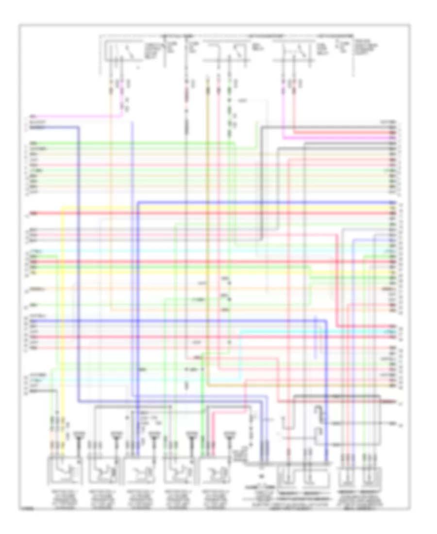
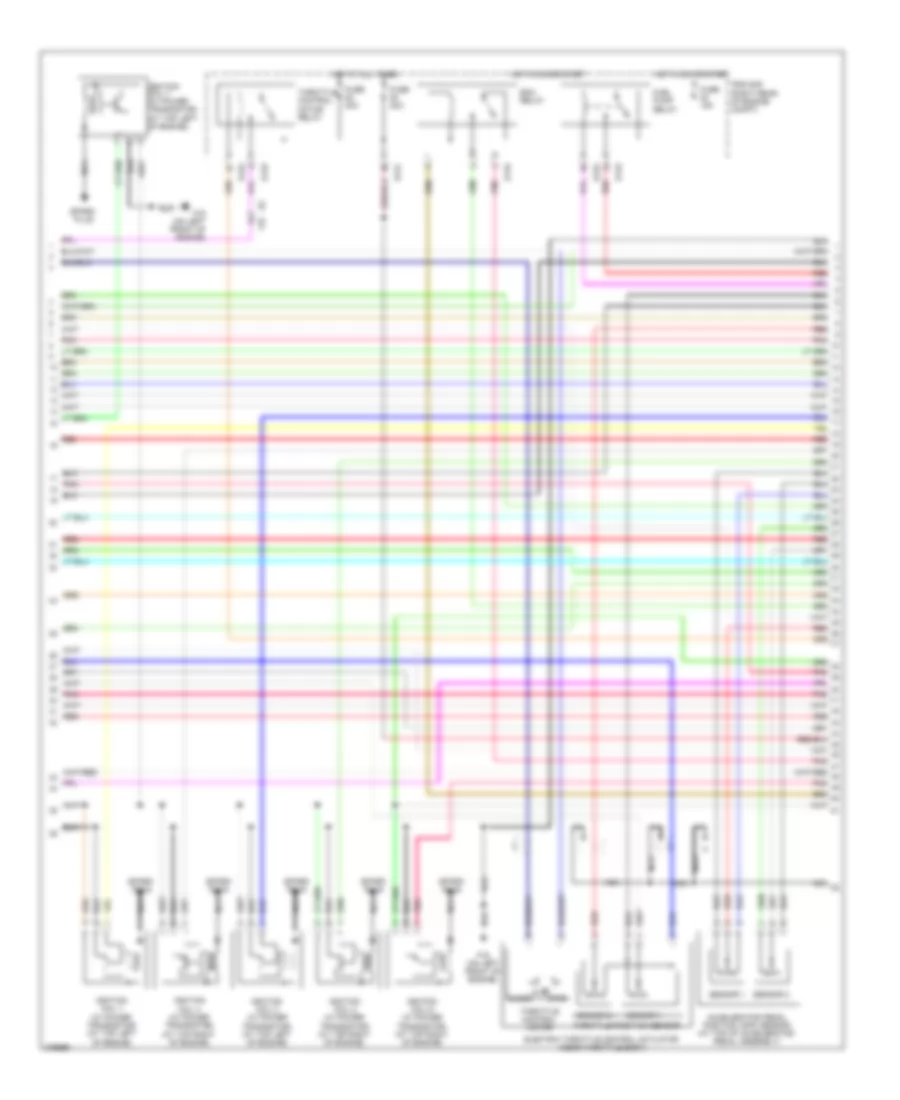
4.0L, Engine Performance Wiring Diagram (1 of 4) for Nissan Pathfinder S 2012
 https://portal-diagnostov.com/license.html
Automotive Electricians Portal FZCO
Automotive Electricians Portal FZCO
https://portal-diagnostov.com/license.html
https://portal-diagnostov.com/license.html
Automotive Electricians Portal FZCO
Automotive Electricians Portal FZCO
List of elements for 4.0L, Engine Performance Wiring Diagram (1 of 4) for Nissan Pathfinder S 2012:
- (at top left of engine) fuel injector
- (at top right of engine) fuel injector
- (on left side of engine) f16
- (right front of engine compt)
- (right front of engine compt) e24
- 15p
- 56g
- Af+1
- Af+2
- Af-1
- Af-h1
- Af-h2
- Avcc
- Avcc (pdp)
- Avcc 2
- Battery current sensor (right front of engine compt)
- Camshaft position sensor (phase) (bank 1) (right rear of engine)
- Combination meter
- Computer data lines system
- Condenser 1 (on top of engine)
- Crankshaft position sensor (pos) (at right rear of engine)
- Cruise control system
- Cvtcl
- Cvtcr
- E152
- E24
- Ecm (right rear of engine compt)
- Evap
- Evap canister purge volume control solenoid valve (on left side of engine)
- F14 e5
- F201
- F201 f44
- F225
- F26
- F44
- F54
- F67 f250
- Ftprs
- Fuse 10a
- Fuse block (j/b) (behind right end of dash)
- Gnd
- Hot in on or start
- Ignition coil 5 (w/ power transistor) (at top right of engine)
- Inj 1
- Inj 2
- Inj 3
- Inj 4
- Inj 5
- Inj 6
- Knk
- Knk 1
- Knk 2
- Knock sensor (bank 1) (on left side of engine)
- Knock sensor (bank 2) (on right side of engine)
- M31
- Malfunction indicator lamp
- Motor 1
- Motor 2
- Nca
- O2hrl
- O2hrr
- O2srl
- Phase (lh)
- Phase (rh)
- Pnk
- Pos
- Ps pres
- Pwr sply
- Pwr sup
- Qa+
- Red
- Refrigerant pressure sensor (right front of engine compt)
- Sig
- Spark plug
- Tps 1
- Unified meter control unit (w/ information display)
- Vias
- Vmot
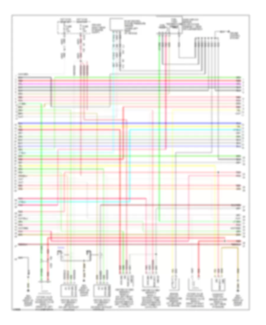
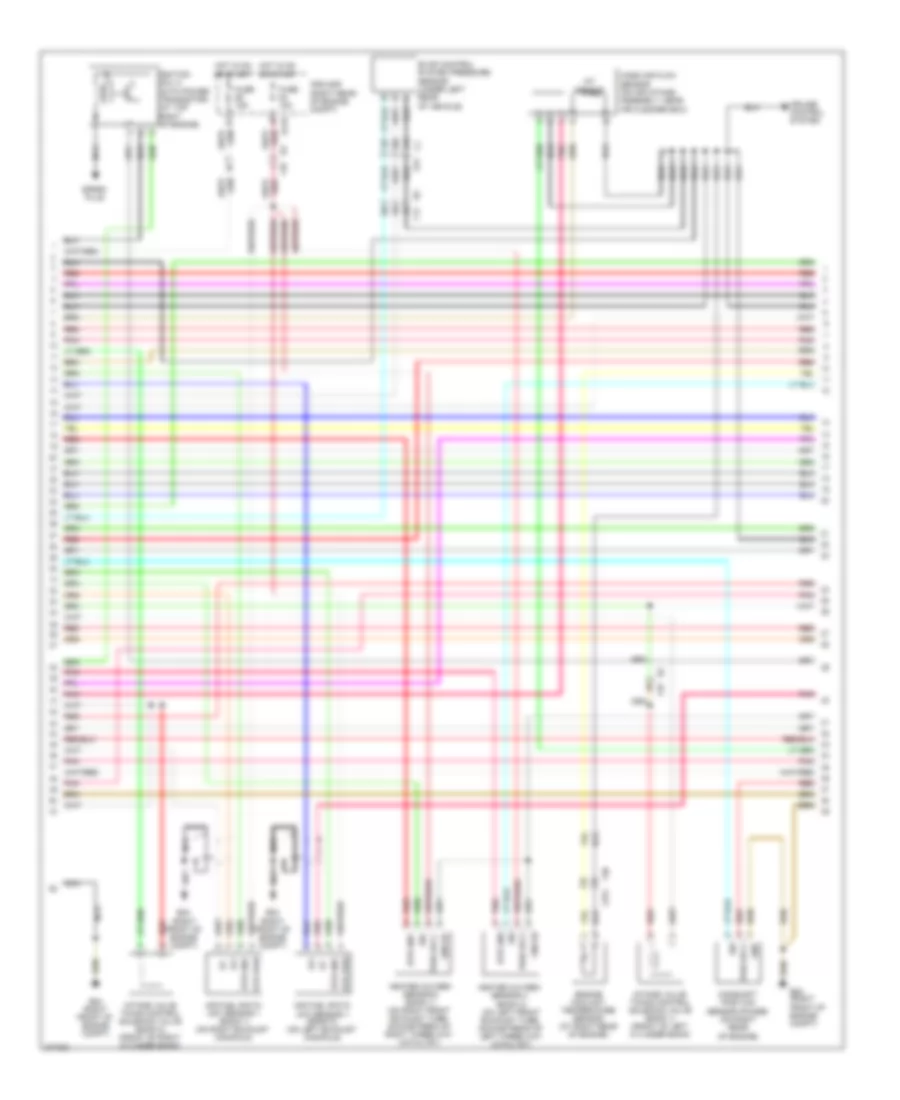
4.0L, Engine Performance Wiring Diagram (2 of 4) for Nissan Pathfinder S 2012
 https://portal-diagnostov.com/license.html
Automotive Electricians Portal FZCO
Automotive Electricians Portal FZCO
https://portal-diagnostov.com/license.html
https://portal-diagnostov.com/license.html
Automotive Electricians Portal FZCO
Automotive Electricians Portal FZCOList of elements for 4.0L, Engine Performance Wiring Diagram (2 of 4) for Nissan Pathfinder S 2012:
- Accelerator pedal position (app) sensor (at top of accelerator pedal assembly)
- Close
- E119
- E121
- E122
- Ecm relay
- Electric throttle control actuator (near throttle body)
- F16 (on left side of engine)
- F225
- F26
- F26 f225
- F32
- Fuel pump relay
- Fuse 15a
- Fuse 20a
- Hot at all times
- Hot in on or start
- Ignition coil 1 (w/ power transistor) (at top right of engine)
- Ignition coil 2 (w/ power transistor) (at top left of engine)
- Ignition coil 3 (w/ power transistor) (at top right of engine)
- Ignition coil 4 (w/ power transistor) (at top left of engine)
- Ignition coil 6 (w/ power transistor) (at top left of engine)
- Ipdm e/r (right rear of engine compt)
- Nca
- Open
- Pnk
- Red
- Sensor 1
- Sensor 2
- Spark plug
- Throttle control motor
- Throttle control motor relay
- Throttle position sensor
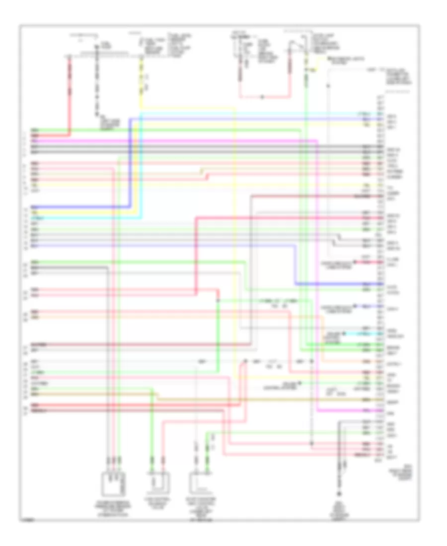
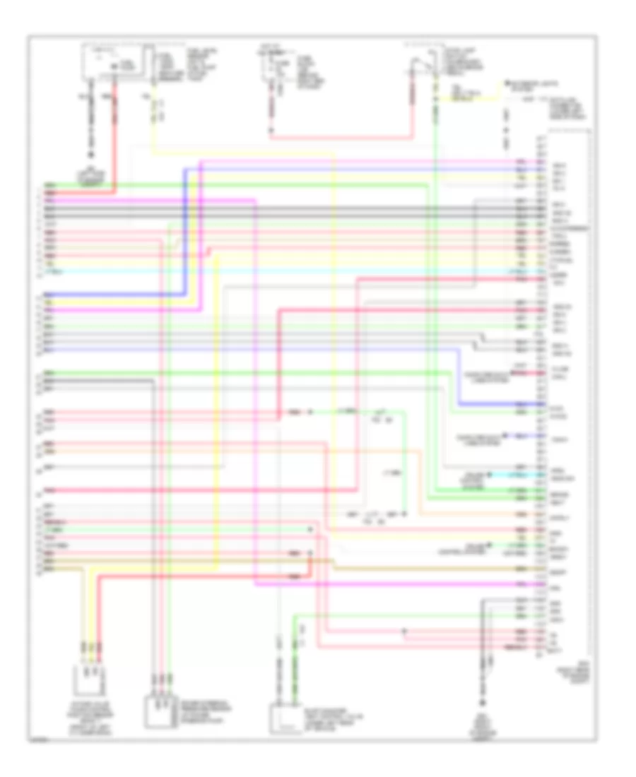
4.0L, Engine Performance Wiring Diagram (3 of 4) for Nissan Pathfinder S 2012
 https://portal-diagnostov.com/license.html
Automotive Electricians Portal FZCO
Automotive Electricians Portal FZCO
https://portal-diagnostov.com/license.html
https://portal-diagnostov.com/license.html
Automotive Electricians Portal FZCO
Automotive Electricians Portal FZCOList of elements for 4.0L, Engine Performance Wiring Diagram (3 of 4) for Nissan Pathfinder S 2012:
- 10c
- 11c
- 12c
- Af+
- Af-
- Air fuel ratio (a/f) sensor 1 (bank 1) (on right exhaust
- Air fuel ratio (a/f) sensor 1 (bank 2) (on left exhaust manifold)
- C1 e41
- Camshaft position sensor (phase) (bank 2) (on left rear of engine)
- Cruise control system
- E119
- E2 f32
- E24 (right front of engine compt)
- E5 f14
- Engine coolant temperature sensor (at left side of engine)
- Evap control system pressure sensor (under left rear of vehicle)
- F225
- F26
- Fuel pump
- Fuel tank temperature sensor
- Fuse 15a
- Gnd
- Gnd 02
- Heated oxygen sensor 2 (bank 1) (on right front exhaust tube, downstream of right three way catalyst)
- Heated oxygen sensor 2 (bank 2) (on left front exhaust tube, downstream of left three way catalyst)
- Hot in on or start
- Htr gnd
- Htr pwr
- Intake valve timing control solenoid valve (bank 1) (front of left cylinder bank)
- Intake valve timing control solenoid valve (bank 2) (front of right cylinder bank)
- Ipdm e/r (right rear of engine compt)
- Manifold)
- Mass airflow sensor (on air intake assembly, near air cleaner box)
- Nca
- Pnk
- Pwr sply
- Red
- Sig
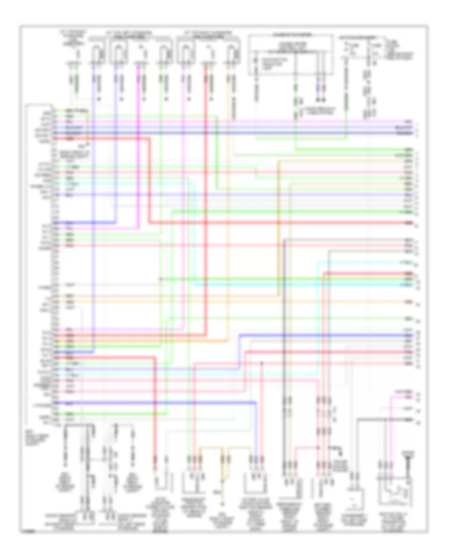
4.0L, Engine Performance Wiring Diagram (4 of 4) for Nissan Pathfinder S 2012
 https://portal-diagnostov.com/license.html
Automotive Electricians Portal FZCO
Automotive Electricians Portal FZCO
https://portal-diagnostov.com/license.html
https://portal-diagnostov.com/license.html
Automotive Electricians Portal FZCO
Automotive Electricians Portal FZCOList of elements for 4.0L, Engine Performance Wiring Diagram (4 of 4) for Nissan Pathfinder S 2012:
- 26c
- 27c
- 28c
- 29c
- 41g m31
- Af-2
- Aps1
- Aps2
- Ascd sw
- Avcc
- Avcc2
- Batt
- Bncsw
- Brake
- Can h
- Can l
- Cdcv
- Computer data lines system
- Cruise control system
- Cursen
- Data link connector (lower left side of dash)
- E152
- E16
- E160
- E24 (right front of engine compt)
- E41
- E9 (left side of engine compt)
- Ecm (right rear of engine compt)
- Evap canister vent control valve (under left rear of vehicle)
- Exterior lights system
- F32
- F54
- Fpr
- Fuel level sensor unit & fuel pump (in fuel tank)
- Fuel pump
- Fuel tank temp- erature sensor
- Fuse 10a
- Fuse block (j/b) (behind right end of dash)
- Gnd
- Gnd 02
- Gnd a
- Gnd a2
- Hot at all times
- Ign 1
- Ign 2
- Ign 3
- Ign 4
- Ign 5
- Ign 6
- Ignsw
- K line
- Motrly
- Neut
- O2srr
- Pd pres
- Pnk
- Power steering pressure sensor (at power steering pump)
- Pwr sply
- Red
- Sig
- Ssoff
- Stop lamp switch (on bracket, above brake pedal)
- Tps 2
- Vias control solenoid valve
5.6L
5.6L, Engine Performance Wiring Diagram (1 of 4) for Nissan Pathfinder S 2012
 https://portal-diagnostov.com/license.html
Automotive Electricians Portal FZCO
Automotive Electricians Portal FZCO
https://portal-diagnostov.com/license.html
https://portal-diagnostov.com/license.html
Automotive Electricians Portal FZCO
Automotive Electricians Portal FZCOList of elements for 5.6L, Engine Performance Wiring Diagram (1 of 4) for Nissan Pathfinder S 2012:
- (at top left of engine) fuel injectors
- (at top right of engine) fuel injector 8
- (at top right of engine) fuel injectors
- (right front of engine compt)
- 15p
- 41g
- 56g
- Af+1
- Af+2
- Af-1
- Af-h1
- Af-h2
- Avcc 2
- Avcc avcc (pdpres)
- Battery current sensor (right front of engine compt)
- Combination meter
- Computer data lines system
- Condenser 1 (on left side of engine)
- Crankshaft position sensor (pos) (at rear of engine)
- Cruise control system
- Cvtcl
- Cvtcr
- E152
- E24
- E24 (right front of engine compt)
- Ecm (right rear of engine compt)
- Evap
- Evap canister purge volume control solenoid valve (on left side of engine)
- F14 e5
- F38 f275
- F79
- Ftprs
- Fuse 10a
- Fuse block (j/b) (behind right end of dash)
- Gnd
- Hot in on or start
- Ign 7
- Ignition coil 5 (w/ power transistor) (at top left of engine)
- Inj 1
- Inj 2
- Inj 3
- Inj 4
- Inj 5
- Inj 6
- Inj 7
- Intake valve timing control position sensor (bank 2) (front of right cylinder bank)
- Knk
- Knk 1
- Knk 2
- Knock sensor (bank 1) (on left rear of engine)
- Knock sensor (bank 2) (on right rear of engine)
- M31
- Malfunction indicator lamp
- Motor 1
- Motor 2
- Nca
- O2hrl
- O2hrr
- O2srl
- Phase (lh)
- Pnk
- Pos
- Ps pres
- Pwr sply
- Qa+
- Red
- Refrigerant pressure sensor (right front of engine compt)
- Sig
- Spark plug
- Tps 1
- Unified meter control unit (w/ information display)
- Vmot
- Vtcpusr
5.6L, Engine Performance Wiring Diagram (2 of 4) for Nissan Pathfinder S 2012
 https://portal-diagnostov.com/license.html
Automotive Electricians Portal FZCO
Automotive Electricians Portal FZCO
https://portal-diagnostov.com/license.html
https://portal-diagnostov.com/license.html
Automotive Electricians Portal FZCO
Automotive Electricians Portal FZCOList of elements for 5.6L, Engine Performance Wiring Diagram (2 of 4) for Nissan Pathfinder S 2012:
- Accelerator pedal position (app) sensor (at top of accelerator pedal assembly)
- Close
- E119
- E121
- E122
- E2 f32
- Ecm relay
- Electric throttle control actuator (near throttle body)
- F16 (on left front of engine)
- Fuel pump relay
- Fuse 15a
- Fuse 20a
- Hot at all times
- Hot in on or start
- Ignition coil 1 (w/ power transistor) (at top left of engine)
- Ignition coil 2 (w/ power transistor) (at top right of engine)
- Ignition coil 3 (w/ power transistor) (at top left of engine)
- Ignition coil 4 (w/ power transistor) (at top right of engine)
- Ignition coil 6 (w/ power transistor) (at top right of engine)
- Ignition coil 7 (w/ power transistor) (at top left of engine)
- Ipdm e/r (right rear of engine compt)
- Nca
- Open
- Pnk
- Red
- Sensor 1
- Sensor 2
- Spark plug
- Throttle control motor
- Throttle control motor relay
- Throttle position sensor
5.6L, Engine Performance Wiring Diagram (3 of 4) for Nissan Pathfinder S 2012
 https://portal-diagnostov.com/license.html
Automotive Electricians Portal FZCO
Automotive Electricians Portal FZCO
https://portal-diagnostov.com/license.html
https://portal-diagnostov.com/license.html
Automotive Electricians Portal FZCO
Automotive Electricians Portal FZCOList of elements for 5.6L, Engine Performance Wiring Diagram (3 of 4) for Nissan Pathfinder S 2012:
- 10c
- 11c
- 12c
- Af+
- Af-
- Air fuel ratio (a/f) sensor 1 (bank 1) (on right exhaust manifold)
- Air fuel ratio (a/f) sensor 1 (bank 2) (on left exhaust manifold)
- C1 e41
- Camshaft position sensor (phase) (on right rear of engine)
- Cruise control system
- E119
- E24 (right front of engine compt)
- Engine coolant temperature sensor (at right rear of engine)
- Evap control system pressure sensor (under left rear of vehicle)
- F14
- F275
- F32
- F38
- Fuse 15a
- Gnd
- Gnd 02
- Heated oxygen sensor 2 (bank 1) (on right front exhaust tube, downstream of right three way catalyst)
- Heated oxygen sensor 2 (bank 2) (on left front exhaust tube, downstream of left three way catalyst)
- Hot in on or start
- Htr gnd
- Htr pwr
- Iat sensor
- Ignition coil 8 (with power transistor) (at top right of engine)
- Intake valve timing control solenoid valve (bank 1) (front of left cylinder bank)
- Intake valve timing control solenoid valve (bank 2) (front of right cylinder bank)
- Ipdm e/r (right rear of engine compt)
- Mass air flow sensor (on air intake assembly, near air cleaner box)
- Nca
- Pnk
- Pwr sply
- Red
- Sig
- Spark plug
5.6L, Engine Performance Wiring Diagram (4 of 4) for Nissan Pathfinder S 2012
 https://portal-diagnostov.com/license.html
Automotive Electricians Portal FZCO
Automotive Electricians Portal FZCO
https://portal-diagnostov.com/license.html
https://portal-diagnostov.com/license.html
Automotive Electricians Portal FZCO
Automotive Electricians Portal FZCOList of elements for 5.6L, Engine Performance Wiring Diagram (4 of 4) for Nissan Pathfinder S 2012:
- 26c
- 27c
- 28c
- 29c
- Af-2
- Aps1
- Aps2
- Ascd sw
- Avcc
- Avcc(psress)
- Avcc2
- Batt
- Bncsw
- Brake
- C1 e41
- Can-h
- Can-l
- Cdcv
- Computer data lines system
- Cruise control system
- Cursen
- Data link connector (lower left side of dash)
- E160
- E24 (right front of engine compt)
- E41 c1
- E9 (left side of engine compt)
- Ecm (right rear of engine compt)
- Evap canister vent control valve (under left rear of vehicle)
- Exterior lights system
- F32
- F79
- Fpr
- Fuel level sensor unit & fuel pump (in fuel tank)
- Fuel pump
- Fuel tank temp- erature sensor
- Fuse 10a
- Fuse block (j/b) (behind right end of dash)
- Gnd
- Gnd 02
- Gnd a
- Gnd a2
- Hot at all times
- Ign 1
- Ign 2
- Ign 3
- Ign 4
- Ign 5
- Ign 6
- Ign 8
- Ignsw
- Inj 8
- Intake valve timing control position sensor (bank 1) (front of left cylinder bank)
- K-line
- Motrly
- Neut
- O2srr
- Pdpres
- Pnk
- Power steering pressure sensor (at power steering pump)
- Pwr sply
- Red
- Sig
- Ssoff
- Stop lamp switch (on bracket, above brake pedal)
- Tps 2
- Vtcpusl

 Čeština
 Dansk
Dansk Deutsch
 Ελληνικά
 English
 English
 Español
 Suomi
Suomi Français
 Français
 עברית
עברית Hrvatski
 Magyar
 Italiano
 한국어
한국어 Nederlands
 Polski
 Português
 Português
 Română
 Русский
 Slovenčina
 Slovenščina
 Svenska
 Türkçe
 中文 (中国)
