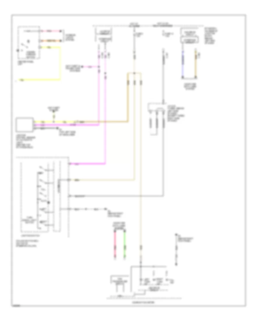
EXTERIOR LIGHTS
Backup Lamps Wiring Diagram, Evolution for Mitsubishi Lancer GT 2012
 https://portal-diagnostov.com/license.html
Automotive Electricians Portal FZCO
Automotive Electricians Portal FZCO
https://portal-diagnostov.com/license.html
https://portal-diagnostov.com/license.html
Automotive Electricians Portal FZCO
Automotive Electricians Portal FZCO
List of elements for Backup Lamps Wiring Diagram, Evolution for Mitsubishi Lancer GT 2012:
- A-13
- Backup light switch (on transmission)
- C-27
- C-304
- C-311
- C-313
- C-47
- Cpu
- D-17
- Etacs-ecu (on rear of junction block, behind left end of dash)
- Except m/t
- F-27
- Fuse 7.5a
- G11 (left side of luggage compt)
- High side switch (r)
- Hot w/ ig1 relay energized
- Joint connector c-43 (left kick panel)
- Left backup light
- Lever position sensor (r)
- M/t
- Nca
- Right backup light
- Shift lever (center console)
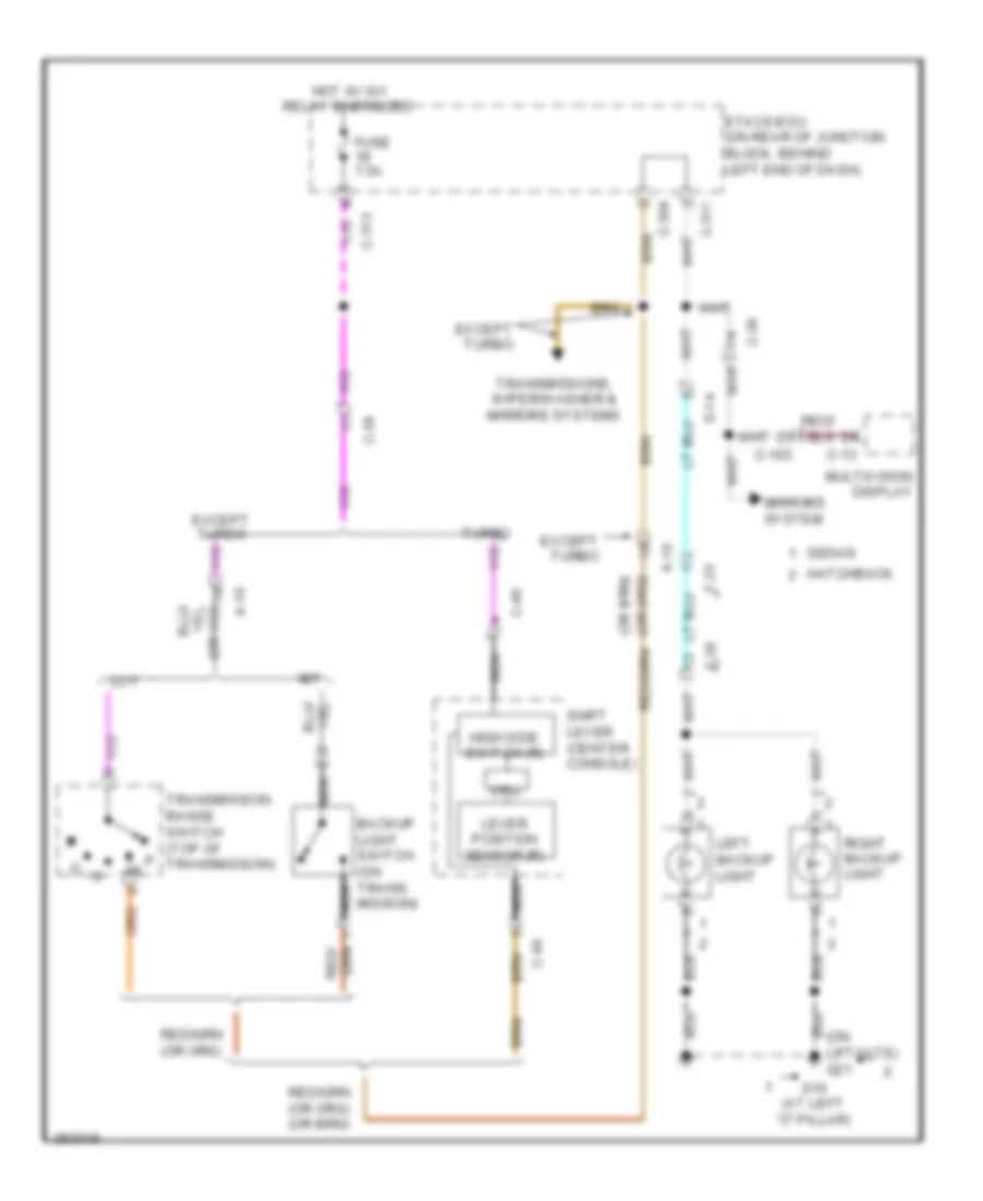
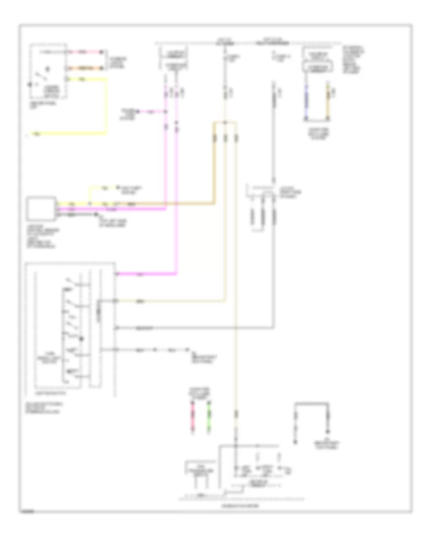
Backup Lamps Wiring Diagram, Except Evolution for Mitsubishi Lancer GT 2012
 https://portal-diagnostov.com/license.html
Automotive Electricians Portal FZCO
Automotive Electricians Portal FZCO
https://portal-diagnostov.com/license.html
https://portal-diagnostov.com/license.html
Automotive Electricians Portal FZCO
Automotive Electricians Portal FZCOList of elements for Backup Lamps Wiring Diagram, Except Evolution for Mitsubishi Lancer GT 2012:
- (on liftgate) g21
- A-10
- Backup light switch (on trans- mission)
- C-103
- C-13
- C-304
- C-311
- C-313
- C-36
- C-39
- C-49
- Cpu
- Cvt
- D-14
- Etacs-ecu (on rear of junction block, behind left end of dash)
- Except turbo
- F-23
- F-30
- Fuse 7.5a
- G10 (at left "c" pillar)
- Hatchback
- High side switch (r)
- Hot w/ ig1 relay energized
- Left backup light
- Lever position sensor (r)
- M/t
- Mirrors system
- Multivision display
- Nca
- Right backup light
- Sedan
- Shift lever (center console)
- Transmission range switch (top of p transmission)
- Transmissions, wiper/washer & mirrors systems
- Turbo
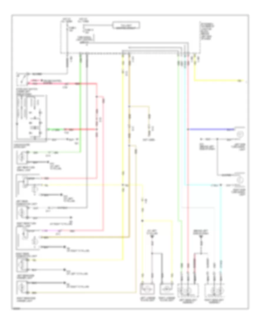
Exterior Lamps Wiring Diagram, Evolution (1 of 2) for Mitsubishi Lancer GT 2012
 https://portal-diagnostov.com/license.html
Automotive Electricians Portal FZCO
Automotive Electricians Portal FZCO
https://portal-diagnostov.com/license.html
https://portal-diagnostov.com/license.html
Automotive Electricians Portal FZCO
Automotive Electricians Portal FZCOList of elements for Exterior Lamps Wiring Diagram, Evolution (1 of 2) for Mitsubishi Lancer GT 2012:
- (left side of luggage compt) g11
- (right of accelerator pedal) g5
- C-301
- C-304
- C-311
- C-47
- Cruise control system
- D-11
- D-16
- D-17
- Etacs-ecu (on rear of junction block, behind left end of dash)
- F-27
- Fuse 10 15a
- Fuse 2 15a
- G11 (left side of luggage compt)
- G5 (right of accelerator pedal)
- G9 (at right "c" pillar)
- High-mounted stoplight
- Hot at all times
- Joint connector c-43 (left kick panel)
- Left headlight assembly
- Left license plate light
- Left rear combination light
- Left rear side marker light
- Left side turn signal light
- Nca
- Pnk
- Red
- Right headlight assembly
- Right license plate light
- Right rear combination light
- Right rear side marker light
- Right side turn signal light
- Stop
- Stoplight switch (under left side of dash)
- Tail
- Taillight control circuit
- Turn
- Turn signal light control circuit
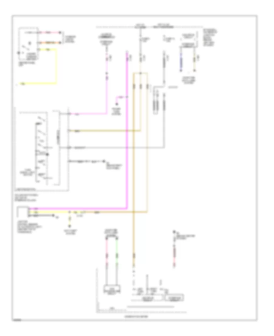
Exterior Lamps Wiring Diagram, Evolution (2 of 2) for Mitsubishi Lancer GT 2012
 https://portal-diagnostov.com/license.html
Automotive Electricians Portal FZCO
Automotive Electricians Portal FZCO
https://portal-diagnostov.com/license.html
https://portal-diagnostov.com/license.html
Automotive Electricians Portal FZCO
Automotive Electricians Portal FZCOList of elements for Exterior Lamps Wiring Diagram, Evolution (2 of 2) for Mitsubishi Lancer GT 2012:
- Anti-theft system
- Auto
- C-133
- C-301
- C-316
- C-317
- Can drive circuit
- Can transceiver circuit
- Center panel unit
- Column ecu
- Column switch-ecu (on top of steering column)
- Combination meter
- Computer data lines system
- Cpu
- Etacs-ecu (on rear of junction block, behind left end of dash)
- Fuse 12 7.5a
- Fuse 8 7.5a
- G4 (behind right kick panel)
- G6 (behind center of dash)
- Hazard warning switch
- Head
- Hot at all times
- Hot w/ ig1 relay energized
- Interface circuit
- Interior lights system
- J/c c-101
- Led drive circuit
- Left
- Left turn ind
- Lighting control sensor (w/ automatic light) (center top of windshield)
- Lighting switch
- Lin drive circuit
- Pnk
- Power tops system
- Right
- Right turn ind
- Tail
- Tail ind
- Turn signal light switch
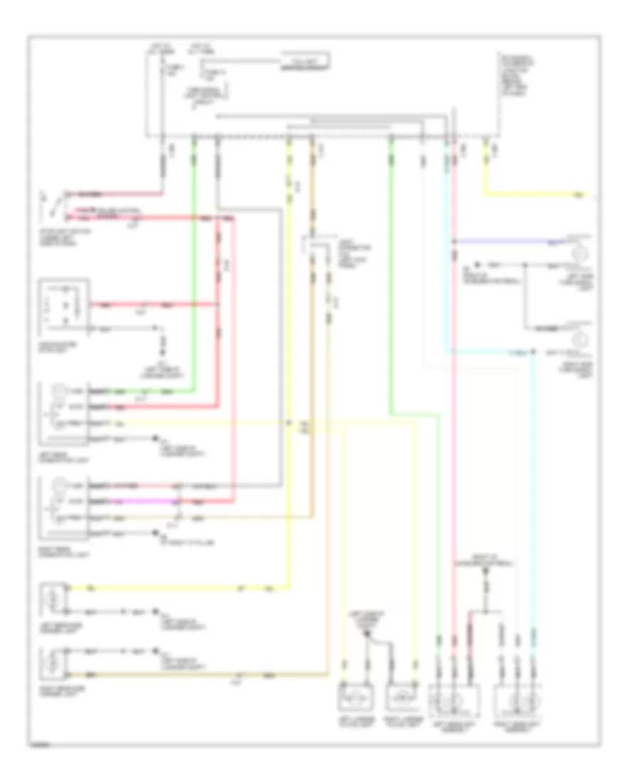
Exterior Lamps Wiring Diagram, Except Evolution (1 of 2) for Mitsubishi Lancer GT 2012
 https://portal-diagnostov.com/license.html
Automotive Electricians Portal FZCO
Automotive Electricians Portal FZCO
https://portal-diagnostov.com/license.html
https://portal-diagnostov.com/license.html
Automotive Electricians Portal FZCO
Automotive Electricians Portal FZCOList of elements for Exterior Lamps Wiring Diagram, Except Evolution (1 of 2) for Mitsubishi Lancer GT 2012:
- (at left "c" pillar) g10
- (rear of engine compt) g16
- C-301
- C-304
- C-311
- C-39
- Control cruise system
- D-11
- D-14
- D-15
- D-23
- Engine controls, anti-lock brakes, cruise control, shift interlock & transmissions systems
- Etacs-ecu (on rear of junction block, behind left end of dash)
- Except turbo
- F-15
- F-23
- Fuse 10 15a
- Fuse 2 15a
- G10 (at left "c" pillar)
- G13 (behind left side of dash)
- G9 (at right "c" pillar)
- High-mounted stoplight
- Hot at all times
- Left headlight assembly
- Left license plate light
- Left rear combination light
- Left side turn signal light
- Left taillight
- Nca
- Pnk
- Red
- Right headlight assembly
- Right license plate light
- Right rear combination light
- Right side turn signal light
- Right taillight
- Stop
- Stop light switch (under left side of dash)
- Taillight control circuit
- Turbo
- Turn
- Turn signal light control circuit
Exterior Lamps Wiring Diagram, Except Evolution (2 of 2) for Mitsubishi Lancer GT 2012
 https://portal-diagnostov.com/license.html
Automotive Electricians Portal FZCO
Automotive Electricians Portal FZCO
https://portal-diagnostov.com/license.html
https://portal-diagnostov.com/license.html
Automotive Electricians Portal FZCO
Automotive Electricians Portal FZCOList of elements for Exterior Lamps Wiring Diagram, Except Evolution (2 of 2) for Mitsubishi Lancer GT 2012:
- Anti-theft & power tops systems
- Anti-theft system
- Auto
- C-130
- C-301
- C-316
- C-317
- Can drive circuit
- Can transceiver circuit
- Center panel unit
- Column ecu
- Column switch-ecu (on top of steering column)
- Combination meter
- Computer data lines system
- Cpu
- Etacs-ecu (on rear of junction block, behind left end of dash)
- Fuse 12 7.5a
- Fuse 8 7.5a
- G4 (behind right kick panel)
- G7 (top left side of headliner)
- Hazard warning switch
- Head
- Hot at all times
- Hot w/ ig1 relay energized
- Interface circuit
- Interior lights system
- J/c c-03 (turbo: behind left side of dash) (except turbo: right side of dash)
- Led drive circuit
- Left
- Left turn ind
- Lighting control sensor (w/ automatic light) (center top of windshield)
- Lighting switch
- Lin drive circuit
- Pnk
- Right
- Right turn ind
- Tail
- Tail ind
- Turn signal light switch
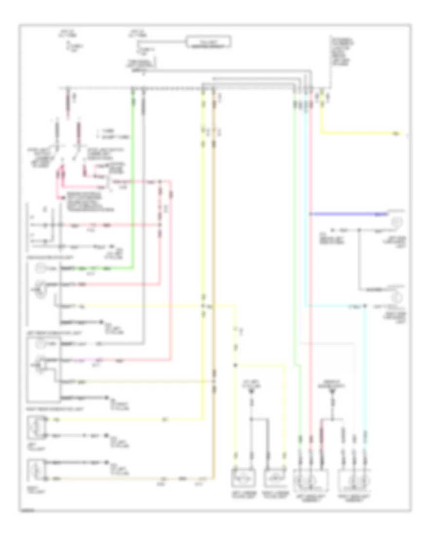
Exterior Lamps Wiring Diagram, Hatchback (1 of 2) for Mitsubishi Lancer GT 2012
 https://portal-diagnostov.com/license.html
Automotive Electricians Portal FZCO
Automotive Electricians Portal FZCO
https://portal-diagnostov.com/license.html
https://portal-diagnostov.com/license.html
Automotive Electricians Portal FZCO
Automotive Electricians Portal FZCOList of elements for Exterior Lamps Wiring Diagram, Hatchback (1 of 2) for Mitsubishi Lancer GT 2012:
- (at left "c" pillar) g10
- (behind left side of dash) g13
- (not used)
- C-301
- C-304
- C-311
- C-39
- Cruise control system
- D-11
- D-14
- D-15
- Etacs-ecu (on rear of junction block, behind left end of dash)
- F-30
- Fuse 10 15a
- Fuse 2 15a
- G10 (at left "c" pillar)
- G13 (behind left side of dash)
- G21
- G9 (at right "c" pillar)
- High-mounted stoplight
- Hot at all times
- Left headlight assembly
- Left license plate light
- Left rear combination light
- Left rear side marker light
- Left rear turn signal lamp
- Left side turn signal light
- Nca
- Pnk
- Red
- Right headlight assembly
- Right license plate light
- Right rear combination light
- Right rear side marker light
- Right rear turn signal lamp
- Right side turn signal light
- Stop
- Stoplight switch (under left side of dash)
- Taillight control circuit
- Turn signal light control circuit
Exterior Lamps Wiring Diagram, Hatchback (2 of 2) for Mitsubishi Lancer GT 2012
 https://portal-diagnostov.com/license.html
Automotive Electricians Portal FZCO
Automotive Electricians Portal FZCO
https://portal-diagnostov.com/license.html
https://portal-diagnostov.com/license.html
Automotive Electricians Portal FZCO
Automotive Electricians Portal FZCOList of elements for Exterior Lamps Wiring Diagram, Hatchback (2 of 2) for Mitsubishi Lancer GT 2012:
- Anti-theft system
- Auto
- C-130
- C-301
- C-316
- C-317
- Can drive circuit
- Can transceiver circuit
- Center panel unit
- Column ecu
- Column switch-ecu (on top of steering column)
- Combination meter
- Computer data lines system
- Cpu
- Etacs-ecu (on rear of junction block, behind left end of dash)
- Fuse 12 7.5a
- Fuse 8 7.5a
- G4 (behind right kick panel)
- G7 (top left side of headliner)
- Hazard warning switch
- Head
- Hot at all times
- Hot w/ ig1 relay energized
- Interface circuit
- Interior lights system
- J/c c-03 (right side of dash)
- Led drive circuit
- Left
- Left turn ind
- Lighting control sensor (w/ automatic light) (center top of windshield)
- Lighting switch
- Lin drive circuit
- Pnk
- Power tops system
- Right
- Right turn ind
- Tail
- Tail ind
- Turn signal light switch

 Čeština
 Dansk
Dansk Deutsch
 Ελληνικά
 English
 English
 Español
 Suomi
Suomi Français
 Français
 עברית
עברית Hrvatski
 Magyar
 Italiano
 한국어
한국어 Nederlands
 Polski
 Português
 Português
 Română
 Русский
 Slovenčina
 Slovenščina
 Svenska
 Türkçe
 中文 (中国)
