POWER DISTRIBUTION
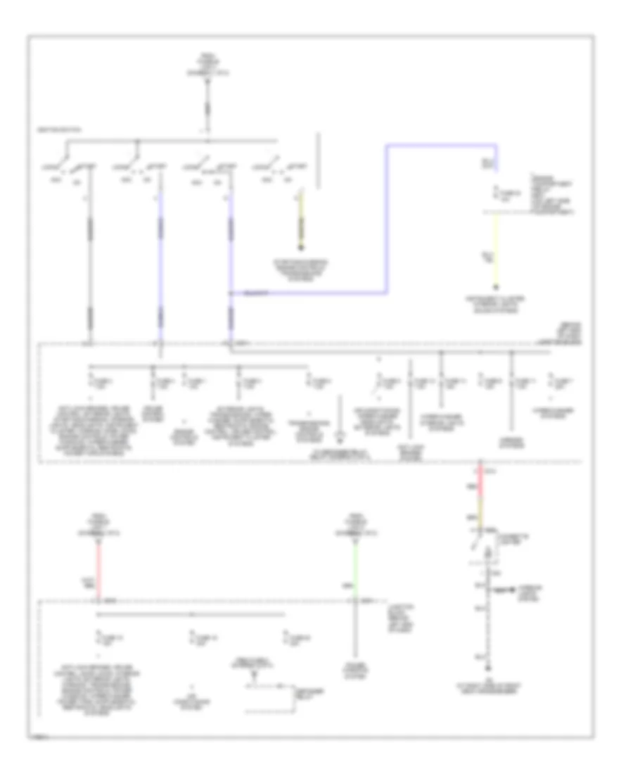
Power Distribution Wiring Diagram (1 of 2) for Mitsubishi Lancer ES 2003
 https://portal-diagnostov.com/license.html
Automotive Electricians Portal FZCO
Automotive Electricians Portal FZCO
https://portal-diagnostov.com/license.html
https://portal-diagnostov.com/license.html
Automotive Electricians Portal FZCO
Automotive Electricians Portal FZCO
List of elements for Power Distribution Wiring Diagram (1 of 2) for Mitsubishi Lancer ES 2003:
- (connected to battery positive terminal)
- Air conditioning system
- Air conditioning, cooling fans systems
- Air conditioning, sound, interior lights, defogger, transmissions, instrument cluster, exterior lights systems
- Anti-lock brakes system
- Anti-lock brakes, cruise control, transmissions, exterior lights systems
- Battery
- Charging system
- Door locks, exterior lights systems
- Engine compartment relay box (on left side of engine compartment)
- Engine controls system
- Engine controls, transmissions systems
- Exterior lights system
- Exterior lights, instrument cluster, transmissions systems
- Front ecu
- Fuse 10 15a
- Fuse 12 7.5a
- Fuse 13 10a
- Fuse 14 20a
- Fuse 15 15a
- Fuse 16 10a
- Fuse 17 10a
- Fuse 18 10a
- Fuse 19 10a
- Fuse 20 7.5a
- Fuse 21 7.5a
- Fuse 22 10a
- Fuse 25 15a
- Fuse 7 10a
- Fuse 8 20a
- Fuse 9 10a
- Fusible link 1 60a
- Fusible link 2 50a
- Fusible link 26 100a
- Fusible link 3 60a
- Fusible link 4 40a
- Fusible link 5 30a
- G10 (w/o turbo) (at rear of cylinder head) (w/ turbo) (at lower left rear of engine)
- G12 (at left front of engine compt, left of battery)
- Headlight relay high
- Headlight relay low
- Headlights system
- Headlights system (canada)
- Horns systems
- Off
- Pnk
- Red
- Sound, door locks, interior lights, instrument cluster, headlights, warning, power windows, wiper/washer, exterior lights systems
- Starting system
- Starting/ charging system
- Taillight relay
- To fuse 15 (diagram 2 of 2)
- To ignition switch (diagram 2 of 2)
- To junction block (diagram 2 of 2)
- Transmissions system
Power Distribution Wiring Diagram (2 of 2) for Mitsubishi Lancer ES 2003
 https://portal-diagnostov.com/license.html
Automotive Electricians Portal FZCO
Automotive Electricians Portal FZCO
https://portal-diagnostov.com/license.html
https://portal-diagnostov.com/license.html
Automotive Electricians Portal FZCO
Automotive Electricians Portal FZCOList of elements for Power Distribution Wiring Diagram (2 of 2) for Mitsubishi Lancer ES 2003:
- (behind left end of dash) junction block
- Acc
- Air conditioning system
- Air conditioning, wiper/washer headlights, exterior lights systems
- Anti-lock brakes system
- C211
- C212
- C214
- Cigarette lighter
- Cruise control system
- D23
- D24
- Defogger relay
- Engine compartment relay box (on left side of engine compartment)
- Engine controls system
- From fuse 5 (diagram 2 of 2)
- From fusible link 1 (diagram 1 of 2)
- From fusible link 4 (diagram 1 of 2)
- From fusible link 5 (diagram 1 of 2)
- Fuse 1 10a
- Fuse 11 7.5a
- Fuse 12 7.5a
- Fuse 14 15a
- Fuse 15 15a
- Fuse 19 30a
- Fuse 2 7.5a
- Fuse 20 30a
- Fuse 23 10a
- Fuse 3 7.5a
- Fuse 4 7.5a
- Fuse 5 7.5a
- Fuse 7 20a
- Fuse 8 7.5a
- Fuse 9 15a
- G3 (at right side of front deck crossmember)
- Ignition switch
- Instrument cluster, interior lights, sound systems
- Interior lights system
- Junction block (behind left end of dash)
- Lock
- Mirrors systems
- Power windows system
- Red
- Start
- Starting/charging, engine controls, transmissions systems
- To defogger relay relay (diagram 2 of 2)
- Transmissions, engine controls systems
- Wiper/washer systems
- Wiper/washer, interior lights systems

 Čeština
 Dansk
Dansk Deutsch
 Ελληνικά
 English
 English
 Español
 Suomi
Suomi Français
 Français
 עברית
עברית Hrvatski
 Magyar
 Italiano
 한국어
한국어 Nederlands
 Polski
 Português
 Português
 Română
 Русский
 Slovenčina
 Slovenščina
 Svenska
 Türkçe
 中文 (中国)
