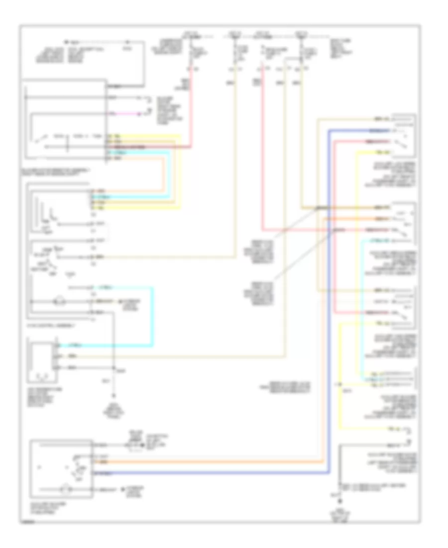
AIR CONDITIONING
Compressor Wiring Diagram for Chevrolet Chevy Express H1500 2007
 https://portal-diagnostov.com/license.html
Automotive Electricians Portal FZCO
Automotive Electricians Portal FZCO
https://portal-diagnostov.com/license.html
https://portal-diagnostov.com/license.html
Automotive Electricians Portal FZCO
Automotive Electricians Portal FZCO
List of elements for Compressor Wiring Diagram for Chevrolet Chevy Express H1500 2007:
- (6.6l)
- (except 6.6l)
- 2006: diesel
- A/c compressor clutch (4.3l : at left front of eng, 6.6l : top front of eng, except 4.3l & 6.6l: at lower right front of eng)
- A/c fuse 32 10a
- A/c high pressure switch (6.6l: on rear of a/c compressor, except 6.6l: on rear portion of a/c compressor)
- A/c low pressure switch (on side of accumulator)
- A/c relay 54
- Bi-lev
- Body fuse block (under left front seat)
- Clutch rly ctrl
- D12
- Def
- F12
- G102 (left front lower side of engine block)
- G102 (on left rear of engine)
- Gasoline
- Heat
- Heat/def
- Hot at all times
- Hot in run
- Hot in run or start
- Hvac control assembly
- Hvac fuse 10 20a
- Ign e fuse 22 10a
- Low press sig
- Max
- Norm
- Off
- Powertrain control module (pcm) (on left inner fender, in engine compt) (gasoline) engine control module (ecm) (left side of engine compt) (diesel)
- Request sig
- S102
- Underhood fuse block (on left side of engine compt)
- Vent
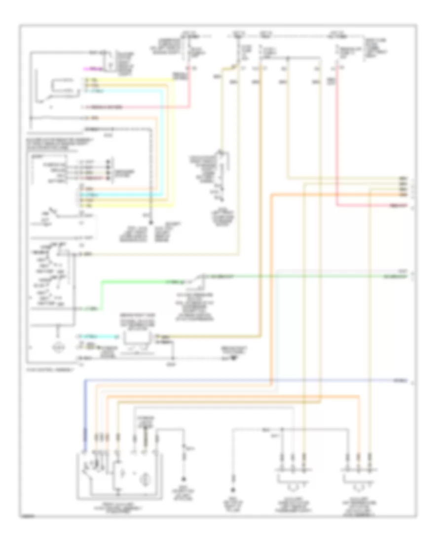
Heater Wiring Diagram for Chevrolet Chevy Express H1500 2007
 https://portal-diagnostov.com/license.html
Automotive Electricians Portal FZCO
Automotive Electricians Portal FZCO
https://portal-diagnostov.com/license.html
https://portal-diagnostov.com/license.html
Automotive Electricians Portal FZCO
Automotive Electricians Portal FZCOList of elements for Heater Wiring Diagram for Chevrolet Chevy Express H1500 2007:
- (6.6l)
- (except 6.6l)
- (on bottom of left "b" pillar) g347
- (on left rear of
- (rear a/c harn, 24 cm from rear blower motor resistor breakout)
- (rear hvac harn, 13 cm from auxiliary blower motor connector breakout)
- (rear hvac harn, 20 cm from auxiliary blower motor connector breakout)
- (w/ rear auxiliary heater) (w/ rear hvac)
- Air temperature actuator (behind right side of dash, on hvac)
- Auxiliary blower motor (if equipped (left rear of passenger
- Auxiliary blower motor resistor (if equipped) (on left rear of
- Auxiliary blower motor switch (if equipped)
- Auxiliary high speed blower motor relay (if equipped) (on left rear of
- Auxiliary low speed blower motor relay (if equipped)
- Auxiliary medium speed blower motor relay (if equipped) (on left rear of
- Bi-lev
- Blow fuse 51 40a
- Blower motor (right rear of engine compt, on evaporator case)
- Blower motor resistor assembly (right rear of engine compt)
- Body fuse block (below left front seat)
- Compt, on auxiliary hvac assembly)
- Def
- F10
- G102 (left front lower side of engine block)
- G102 (on left rear of engine)
- G304 (behind right kick panel)
- G401 (on top of right "d" pillar)
- Heat
- Heat/def
- Hot at all times
- Hot in run
- Hvac 1 fuse 9 10a
- Hvac control assembly
- Hvac fuse 20a
- Interior lights system
- Med
- Off
- Passenger compt, on auxiliary hvac assembly)
- Rr blower fuse 13 30a
- S102
- S249
- S401 s411
- S405
- S412
- S413
- Splice pack sp347
- Tan
- Underhood fuse block (on left side of engine compt)
- Vent
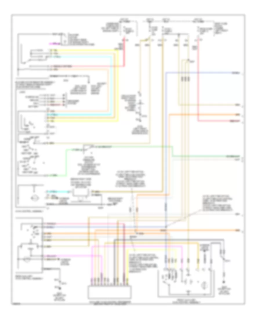
Manual A/C Wiring Diagram, Cargo Van (1 of 3) for Chevrolet Chevy Express H1500 2007
 https://portal-diagnostov.com/license.html
Automotive Electricians Portal FZCO
Automotive Electricians Portal FZCO
https://portal-diagnostov.com/license.html
https://portal-diagnostov.com/license.html
Automotive Electricians Portal FZCO
Automotive Electricians Portal FZCOList of elements for Manual A/C Wiring Diagram, Cargo Van (1 of 3) for Chevrolet Chevy Express H1500 2007:
- (6.6l)
- (behind right kick panel) g304
- (behind right side
- (diesel)
- (except 6.6l)
- A/c high pressure switch (6.6l: on rear of a/c compressor, except 6.6l: on rear portion of a/c compressor)
- Auxiliary air temperature actuator (on auxiliary hvac assembly)
- Auxiliary mode actuator (left rear of passenger compt)
- Battery
- Bi-lev
- Blow fuse 51 40a
- Blower motor (right rear of engine compt)
- Blower motor resistor assembly (at right rear of engine compt, on evaporator case)
- Body fuse block (under left front seat)
- C2 a
- C2 c
- Def
- Defogger system
- F10
- Front auxiliary hvac control assembly (if equipped)
- G102 (left front lower side of engine block)
- G102 (on left rear of engine)
- G347 (on bottom of left "b" pillar)
- G401 (on top of right "d" pillar)
- Ground
- Heat
- Heat/def
- Hot at all times
- Hot in run
- Hvac 1 fuse 9 10a
- Hvac control assembly
- Hvac fuse 20a
- Ing 3
- Interior lights system
- Logic
- Max
- Med
- Norm
- Of dash, on hvac) air temperature actuator
- Off
- R defog ind
- Rear blwr fuse 13 30a
- S102
- S249
- S314
- S411
- Tan
- Underhood fuse block (on left side of engine compt)
- Vacuum pump (right front of engine compt, under battery) a
- Vent
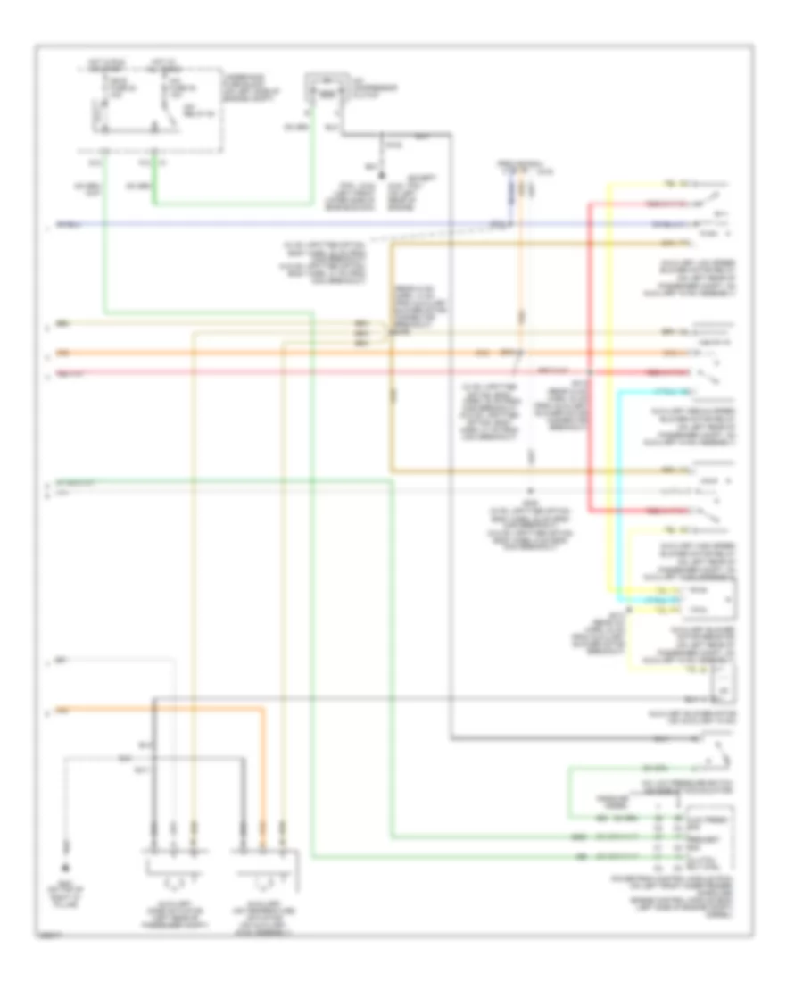
Manual A/C Wiring Diagram, Cargo Van (2 of 3) for Chevrolet Chevy Express H1500 2007
 https://portal-diagnostov.com/license.html
Automotive Electricians Portal FZCO
Automotive Electricians Portal FZCO
https://portal-diagnostov.com/license.html
https://portal-diagnostov.com/license.html
Automotive Electricians Portal FZCO
Automotive Electricians Portal FZCOList of elements for Manual A/C Wiring Diagram, Cargo Van (2 of 3) for Chevrolet Chevy Express H1500 2007:
- (6.6l)
- (except 6.6l)
- (on left rear of
- (provisional)
- (rear hvac harn, 13 cm from auxiliary blower motor connector breakout)
- (top of right "d" pillar) g401
- (w/ rv upfitter
- (w/ rv upfitter option:
- (w/ rv upfitter option: body harn, 22 cm from c308 breakout) (w/o rv upfitter option: body harn, 41 cm from c304 breakout)
- A/c compressor clutch (4.3l: at left front of eng, 4.8l, 5.3l & 6.0l: at lower right front of eng, 6.6l: top front of eng)
- A/c fuse 32 10a
- A/c low pressure switch (on side of accumulator)
- A/c relay 54
- Auxiliary blower motor (if equipped) (on auxiliary hvac)
- Auxiliary blower motor resistor (if equipped)
- Auxiliary high speed blower motor relay (if equipped)
- Auxiliary low speed blower motor relay (if equipped)
- Auxiliary medium speed blower motor relay (if equipped)
- Body harn, 22 cm from c308 breakout) (w/o rv upfitter option: body harn, 5 cm from c304 breakout)
- C319
- Clutch rly ctrl
- D12
- Diesel
- F12
- G102 (left front lower side of engine block)
- G102 (on left rear of engine)
- Gasoline
- Hot at all times
- Hot in run or start
- Ign e fuse 22 10a
- Low press sig
- Option: body harn, 32 cm from c308 breakout) (w/o rv upfitter option: body harn, 31 cm from c304 breakout)
- Passenger compt, on auxiliary hvac assembly)
- Powertrain control module (pcm) (on left front inner fender) (gasoline) engine control module (ecm) (left side of engine compt) (diesel)
- Req sig
- S102
- S308
- S310
- S311
- S405
- S411
- S412 (rear hvac harn, 20 cm from auxiliary blower motor connector breakout)
- S413 (rear a/c harn, 24 cm from aux blower motor breakout)
- Underhood fuse block (on left side of engine compt)
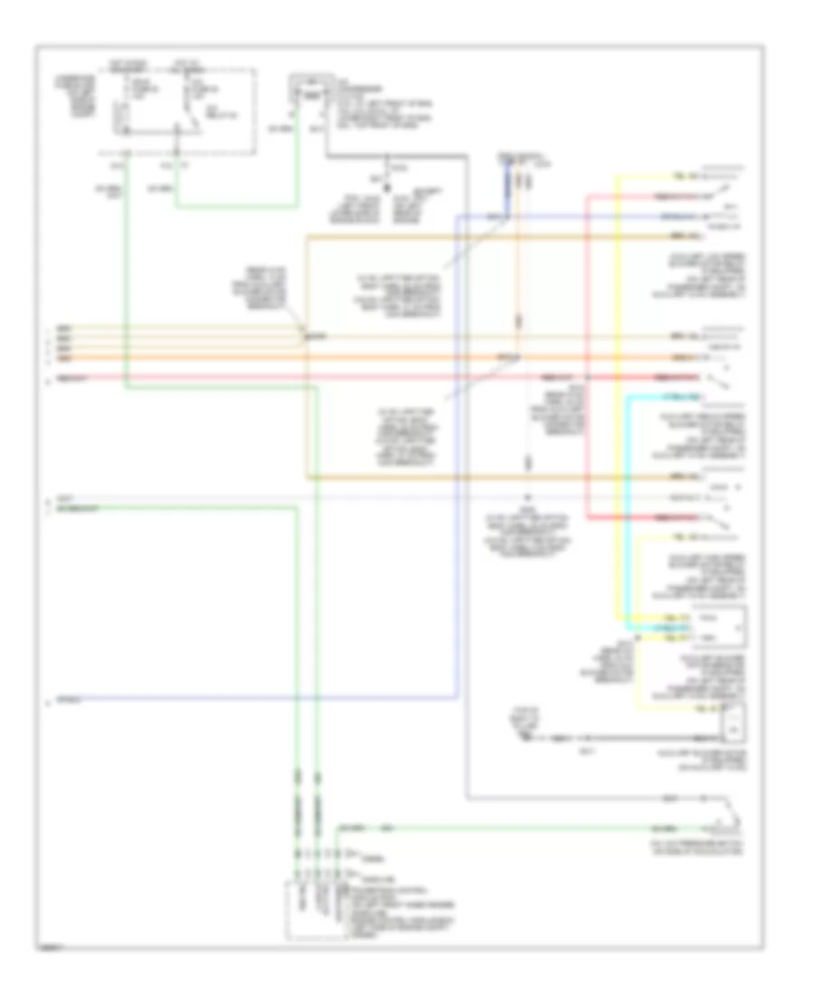
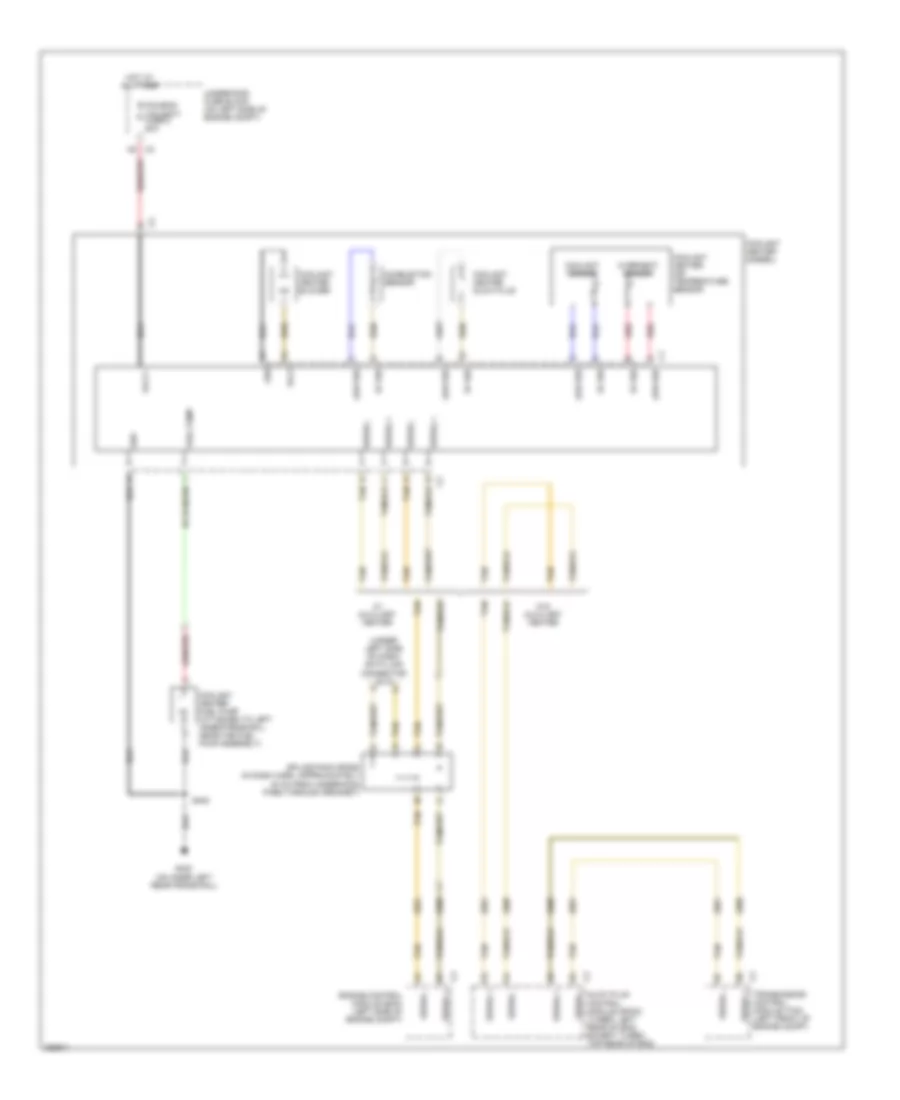
Manual A/C Wiring Diagram, Cargo Van (3 of 3) for Chevrolet Chevy Express H1500 2007
 https://portal-diagnostov.com/license.html
Automotive Electricians Portal FZCO
Automotive Electricians Portal FZCO
https://portal-diagnostov.com/license.html
https://portal-diagnostov.com/license.html
Automotive Electricians Portal FZCO
Automotive Electricians Portal FZCOList of elements for Manual A/C Wiring Diagram, Cargo Van (3 of 3) for Chevrolet Chevy Express H1500 2007:
- (under left side of dash) data link connector (dlc)
- 5v ref
- Combustion sensor
- Coolant heater (diesel)
- Coolant heater air temperature sensor
- Coolant heater blower
- Coolant heater fuel pump (attached to left inner frame rail, near the fuel pump assembly)
- Coolant heater glow plug
- Coolant sensor
- Engine control module (ecm) (left side of engine compt)
- Foh/ecm/ tcm batt fuse 2 20a
- Fuel pump
- G400 (on inner left rear frame rail)
- Glow plug control module (gpcm) (turbo: left rear of eng, except turbo: top rear of eng)
- Grd
- Hot at all times
- Low ref
- Nca
- Overheat sensor
- Red
- S402
- Serial +
- Serial -
- Splice pack sp250 (in dash harn, approximately 20 cm from underhood pass through grommet)
- Tan
- Transmission control module (tcm) (left front of engine compt)
- Underhood fuse block (on left side of engine compt)
- Volt
- Volt +
- W/ auxiliary heater
- W/o auxiliary heater
Manual A/C Wiring Diagram, Passenger Van (1 of 3) for Chevrolet Chevy Express H1500 2007
 https://portal-diagnostov.com/license.html
Automotive Electricians Portal FZCO
Automotive Electricians Portal FZCO
https://portal-diagnostov.com/license.html
https://portal-diagnostov.com/license.html
Automotive Electricians Portal FZCO
Automotive Electricians Portal FZCOList of elements for Manual A/C Wiring Diagram, Passenger Van (1 of 3) for Chevrolet Chevy Express H1500 2007:
- (6.6l)
- (behind right kick panel) g304
- (behind right side
- (diesel)
- (except 6.6l)
- (w/ rv upfitter option:
- (w/ rv upfitter option: in upfitter hvac control harn, 19 cm from c303 breakout) (w/o rv upfitter option: in front headliner harn, 42 cm from c304 breakout)
- (w/ rv upfitter option: in upfitter hvac control harn, 64 cm from c303 breakout) (w/o rv upfitter option: in front headliner harn, 11 cm from c304 breakout)
- A/c high pressure switch (6.6l: on rear of a/c compressor, except 6.6l: on rear portion of a/c compressor)
- Auxiliary hvac control processor (center front of headliner)
- Battery
- Bi-lev
- Blow fuse 51 40a
- Blower motor (on right rear of engine compt, on evaporator case)
- Blower motor resistor assembly (at right rear of engine compt, on evaporator case)
- Body fuse block (under left front seat)
- C1 g
- C2 a
- C2 c
- Def
- Defogger system
- F10
- Front auxiliary hvac control assembly
- G102 (left front lower side of engine block)
- G102 (on left rear of engine)
- G347 (on bottom of left "b" pillar)
- Ground
- Heat
- Heat/def
- Hot at all times
- Hot in run
- Hvac 1 fuse 9 10a
- Hvac control assembly
- Hvac fuse 20a
- In upfitter hvac control harn, 39 cm from c303 breakout) (w/o rv upfitter option: in front headliner harn, 31 cm from c304 breakout)
- Ing 3
- Interior lights system
- Logic
- Max
- Med
- Norm
- Of dash, on hvac) air temperature actuator
- Off
- R defog ind
- Rear
- Rear auxiliary hvac control assembly
- Rr blower fuse 13 30a
- S102
- S249
- S305
- S306
- S307
- S314
- S354
- Tan
- Tan e
- Underhood fuse block (on left side of engine compt)
- Vacuum pump (right front of engine compt, under battery) a
- Vent
Manual A/C Wiring Diagram, Passenger Van (2 of 3) for Chevrolet Chevy Express H1500 2007
 https://portal-diagnostov.com/license.html
Automotive Electricians Portal FZCO
Automotive Electricians Portal FZCO
https://portal-diagnostov.com/license.html
https://portal-diagnostov.com/license.html
Automotive Electricians Portal FZCO
Automotive Electricians Portal FZCOList of elements for Manual A/C Wiring Diagram, Passenger Van (2 of 3) for Chevrolet Chevy Express H1500 2007:
- (6.6l)
- (except 6.6l)
- (on left rear of
- (provisional)
- (rear hvac harn, 13 cm from auxiliary blower motor connector breakout) s405
- (w/ rv upfitter
- (w/ rv upfitter option:
- (w/ rv upfitter option: body harn, 22 cm from c308 breakout) (w/o rv upfitter option: body harn, 41 cm from c304 breakout)
- A/c compressor clutch
- A/c fuse 32 10a
- A/c low pressure switch (on side of accumulator)
- A/c relay 54
- Auxiliary air temperature actuator (on auxiliary hvac assembly)
- Auxiliary blower motor (on auxiliary hvac)
- Auxiliary blower motor resistor
- Auxiliary high speed blower motor relay
- Auxiliary low speed blower motor relay
- Auxiliary medium speed blower motor relay
- Auxiliary mode actuator (left rear of passenger compt)
- Body harn, 22 cm from c308 breakout) (w/o rv upfitter option: body harn, 5 cm from c304 breakout)
- C319
- Clutch rly ctrl c2
- D12
- F12
- G102 (left front lower side of engine block)
- G102 (on left rear of engine)
- G401 (on top of right "d" pillar)
- Gasoline diesel
- Hot at all times
- Hot in run or start
- Ign e fuse 22 10a
- Low press sig c2
- Option: body harn, 32 cm from c308 breakout) (w/o rv upfitter option: body harn, 31 cm from c304 breakout)
- Passenger compt, on auxiliary hvac assembly)
- Powertrain control module (pcm) (on left front inner fender) (gasoline) engine control module (ecm) (left side of engine compt) (diesel)
- Request sig c2
- S102
- S308
- S310
- S311
- S411
- S412 (rear hvac harn, 20 cm from auxiliary blower motor connector breakout)
- S413 (rear a/c harn, 24 cm from auxiliary blower motor breakout)
- Underhood fuse block (on left side of engine compt)
Manual A/C Wiring Diagram, Passenger Van (3 of 3) for Chevrolet Chevy Express H1500 2007
 https://portal-diagnostov.com/license.html
Automotive Electricians Portal FZCO
Automotive Electricians Portal FZCO
https://portal-diagnostov.com/license.html
https://portal-diagnostov.com/license.html
Automotive Electricians Portal FZCO
Automotive Electricians Portal FZCOList of elements for Manual A/C Wiring Diagram, Passenger Van (3 of 3) for Chevrolet Chevy Express H1500 2007:
- (under left side of dash) data link connector (dlc)
- 5v ref
- Combustion sensor
- Coolant heater (diesel)
- Coolant heater air temperature sensor
- Coolant heater blower
- Coolant heater fuel pump (attached to left inner frame rail, near the fuel pump assembly)
- Coolant heater glow plug
- Coolant sensor
- Engine control module (ecm) (left side of engine compt)
- Foh/ecm/ tcm batt fuse 2 20a
- Fuel pump
- G400 (on inner left rear frame rail)
- Glow plug control module (gpcm) (turbo: left rear of eng, except turbo: top rear of eng)
- Grd
- Hot at all times
- Low ref
- Nca
- Overheat sensor
- Red
- S402
- Serial +
- Serial -
- Splice pack sp250 (in dash harn, approximately 20 cm from underhood pass through grommet)
- Tan
- Transmission control module (tcm) (left front of engine compt)
- Underhood fuse block (on left side of engine compt)
- Volt
- Volt +
- W/ auxiliary heater
- W/o auxiliary heater

 Čeština
 Dansk
Dansk Deutsch
 Ελληνικά
 English
 English
 Español
 Suomi
Suomi Français
 Français
 עברית
עברית Hrvatski
 Magyar
 Italiano
 한국어
한국어 Nederlands
 Polski
 Português
 Português
 Română
 Русский
 Slovenčina
 Slovenščina
 Svenska
 Türkçe
 中文 (中国)
