AIR CONDITIONING
2.3L
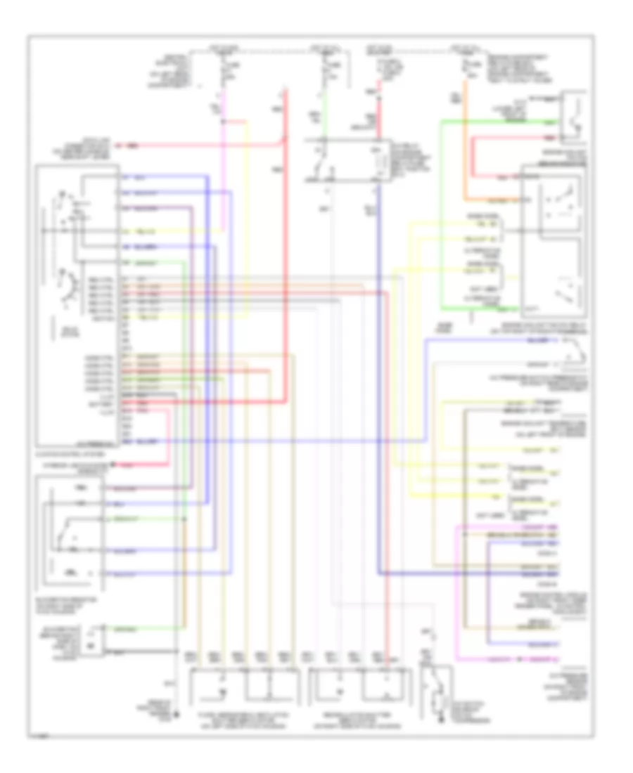
2.3L Turbo, Manual A/C Wiring Diagram for Volvo S70 AWD 1999
 https://portal-diagnostov.com/license.html
Automotive Electricians Portal FZCO
Automotive Electricians Portal FZCO
https://portal-diagnostov.com/license.html
https://portal-diagnostov.com/license.html
Automotive Electricians Portal FZCO
Automotive Electricians Portal FZCO
List of elements for 2.3L Turbo, Manual A/C Wiring Diagram for Volvo S70 AWD 1999:
- (not used)
- (on center console, near shift lever)
- (rear of right front fender) g105
- 87a
- A/c press sw
- A/c pressure sensor (on right front of engine compartment)
- A/c pressure switch (pressostat) (on right rear of engine compartment)
- A/c relay (on engine compartment relay/fuse box, position n0 4)
- A/c switch solenoid (on a/c compressor)
- A39
- A60
- A68
- Alternative model
- B10
- B11
- B12
- B13
- B14
- B15
- B16
- B17
- B18
- B19
- B20
- B21
- B22
- B32
- B44
- Base model
- Battery
- Blower fan (behind right side of dash, on hvac housing)
- Blower fan resistor (on right side of hvac housing)
- C2 red
- Central electrical unit (on left rear of engine compartment)
- Climate control system
- Conn a
- Conn b
- Data link connector (dlc)
- Engine compartment relay/fuse box (on left rear of engine compartment, next to strut tower)
- Engine control module (on right front inner fender panel, in control module box)
- Engine coolant (fc) fan (behind radiator)
- Engine coolant fan (fc) relay (on top right of radiator shroud)
- Engine coolant temperature (ect) sensor (on left front of engine)
- Floor, defroster & ventilation shutter servo motor (on left side of hvac housing)
- Fuse 15a
- Fuse 2 15a, (or fuse 5 20a)
- Fuse 25a
- Fuse 60a
- G110 (lower left front of engine)
- Hot at all times
- Hot in acc or on
- Hot in on or start
- Ignition
- Illum
- Interior lights system (rheostat)
- Mode ctrl
- Out1
- Out2
- Pnk
- Rec ctrl
- Recirculation shutter servo motor (on right side of hvac housing)
- Red
- Solid state
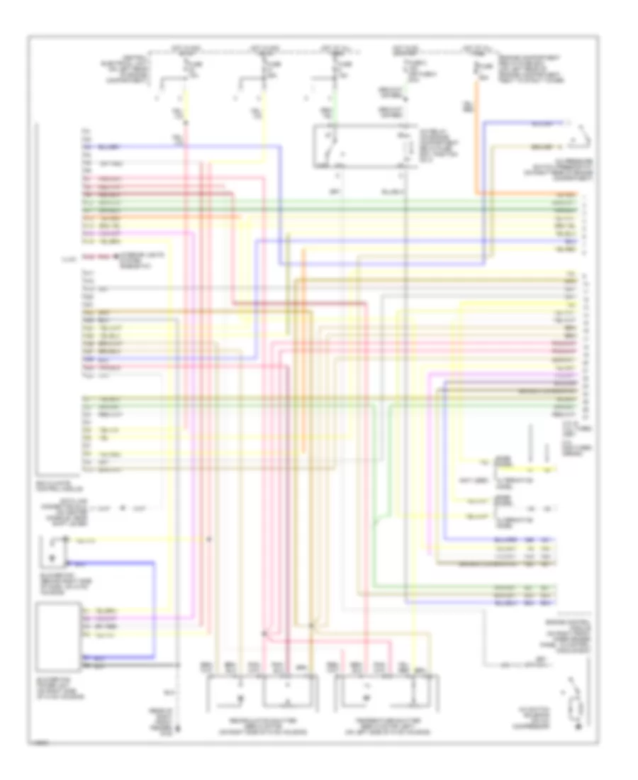
Automatic A/C Wiring Diagram (1 of 2) for Volvo S70 AWD 1999
 https://portal-diagnostov.com/license.html
Automotive Electricians Portal FZCO
Automotive Electricians Portal FZCO
https://portal-diagnostov.com/license.html
https://portal-diagnostov.com/license.html
Automotive Electricians Portal FZCO
Automotive Electricians Portal FZCOList of elements for Automatic A/C Wiring Diagram (1 of 2) for Volvo S70 AWD 1999:
- (not used)
- (rear of right front fender) g105
- 2.3l & 2.4l turbo (me7)
- 2.4l non-turbo (denso)
- 87a
- A/c pressure switch (pressostat) (on right rear of engine compartment)
- A/c relay (on engine compartment relay/fuse box, position no 4)
- A/c switch solenoid (on a/c compressor)
- A10
- A11
- A12
- A13
- A14
- A15
- A16
- A17
- A18
- A19
- A20
- A21
- A22
- A23
- A24
- A25
- A26
- A27
- A28
- A29
- A30
- A39
- A40
- A58
- A60
- A61
- A68
- Alternative model
- B27
- B32
- B44
- Base model
- Blower fan (behind right side of dash, on hvac housing)
- Blower fan power unit (on right side of hvac housing)
- C10
- Central electrical unit (on left rear of engine compartment)
- Data link connector (dlc) (on center console, near shift lever)
- Ecc climate control module
- Engine compartment relay/fuse box (on left rear of engine compartment, next to strut tower)
- Engine control module (on right front inner fender panel, in control module box)
- Fuse 10a
- Fuse 15a
- Fuse 2 15a (or fuse 5 20a)
- Fuse 25a
- Fuse 60a
- Hot at all times
- Hot in acc or on
- Hot in on or start
- Illum
- Interior lights system (rheostat)
- Pnk
- Recirculation shutter servo motor (on right side of hvac housing)
- Temperature shutter servo motor (left) (on left side of hvac housing)
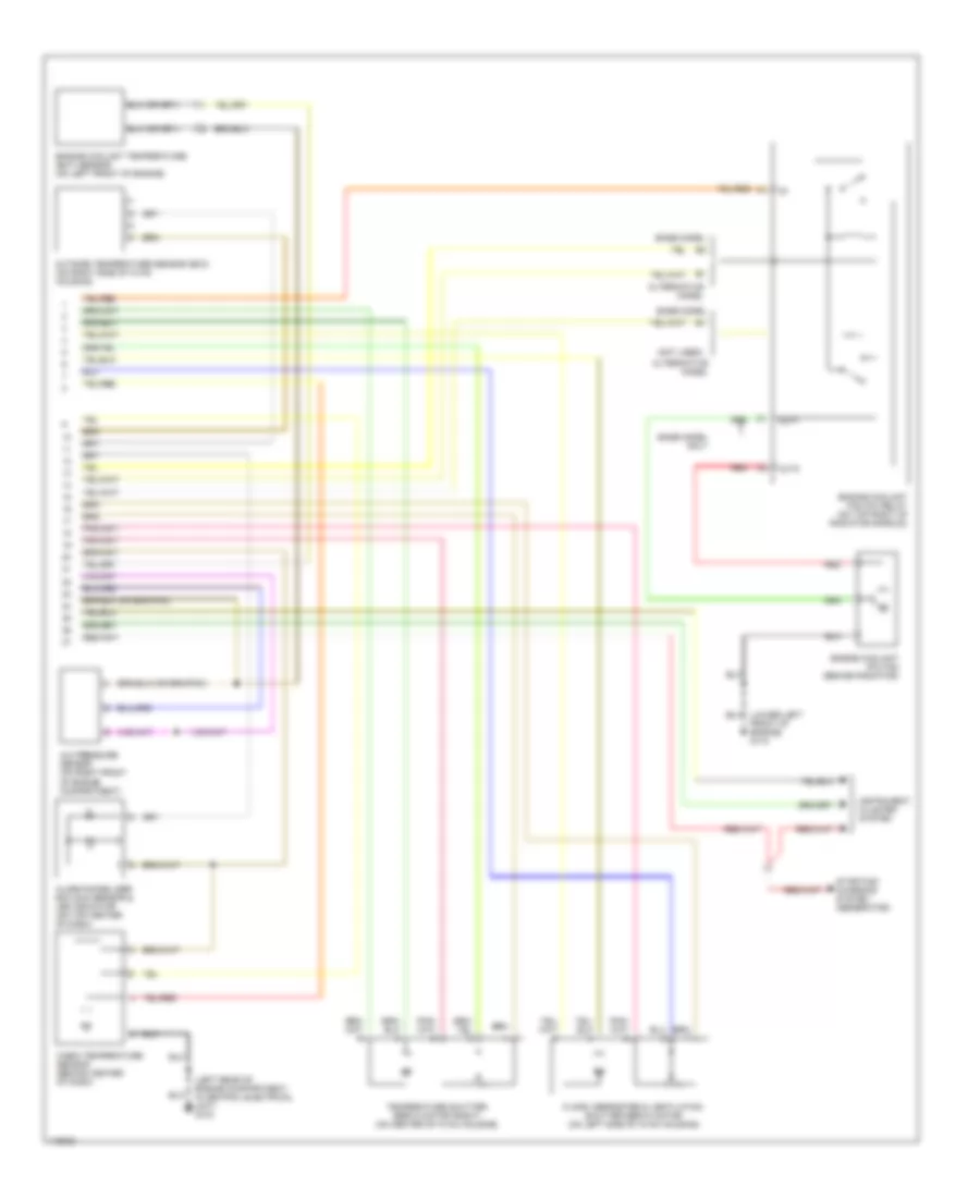
Automatic A/C Wiring Diagram (2 of 2) for Volvo S70 AWD 1999
 https://portal-diagnostov.com/license.html
Automotive Electricians Portal FZCO
Automotive Electricians Portal FZCO
https://portal-diagnostov.com/license.html
https://portal-diagnostov.com/license.html
Automotive Electricians Portal FZCO
Automotive Electricians Portal FZCOList of elements for Automatic A/C Wiring Diagram (2 of 2) for Volvo S70 AWD 1999:
- (left rear of engine compartment, in central electrical unit) g104
- (not used)
- A/c pressure sensor (on right front of engine compartment)
- Alarm/immobilizer ecc sun sensor & led indicator (on top center of dash)
- Alternative model
- Base model
- Base model only
- Cabin temperature sensor (behind center of dash)
- Engine coolant (fc) fan (behind radiator)
- Engine coolant fan (fc) relay (on top right of radiator shroud)
- Engine coolant temperature (ect) sensor (on left front of engine)
- Floor, defroster & ventilation shutter servo motor (on left side of hvac housing)
- Front of engine) g110
- Instrument cluster system
- Out1
- Out2
- Outside temperature sensor (ecc) (on right side of hvac housing)
- Red
- Starting/ charging system (generator)
- Temperature shutter servo motor (right) (on center of hvac housing)
2.4L
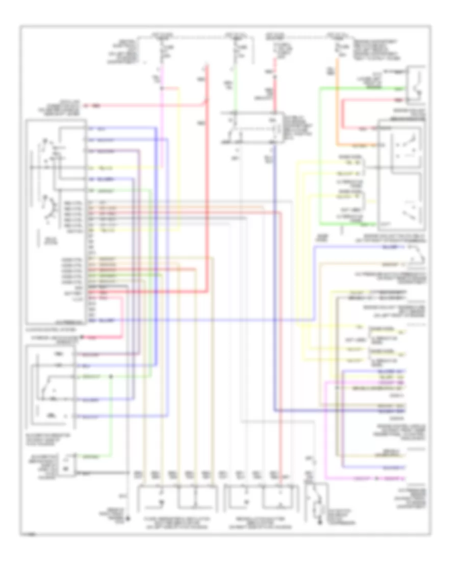
2.4L Turbo, Manual A/C Wiring Diagram for Volvo S70 AWD 1999
 https://portal-diagnostov.com/license.html
Automotive Electricians Portal FZCO
Automotive Electricians Portal FZCO
https://portal-diagnostov.com/license.html
https://portal-diagnostov.com/license.html
Automotive Electricians Portal FZCO
Automotive Electricians Portal FZCOList of elements for 2.4L Turbo, Manual A/C Wiring Diagram for Volvo S70 AWD 1999:
- (not used)
- (on center console, near shift lever)
- (rear of right front fender) g105
- 87a
- A/c press sw
- A/c pressure sensor (on right front of engine compartment)
- A/c pressure switch (pressostat) (on right rear of engine compartment)
- A/c relay (on engine compartment relay/fuse box, position n0 4)
- A/c switch solenoid (on a/c compressor)
- A39
- A60
- A68
- Alternative model
- B10
- B11
- B12
- B13
- B14
- B15
- B16
- B17
- B18
- B19
- B20
- B21
- B22
- B32
- B44
- Base model
- Battery
- Blower fan (behind right side of dash, on hvac housing)
- Blower fan resistor (on right side of hvac housing)
- C2 red
- Central electrical unit (on left rear of engine compartment)
- Climate control system
- Conn a
- Conn b
- Data link connector (dlc)
- Engine compartment relay/fuse box (on left rear of engine compartment, next to strut tower)
- Engine control module (on right front inner fender panel, in control module box)
- Engine coolant (fc) fan (behind radiator)
- Engine coolant fan (fc) relay (on top right of radiator shroud)
- Engine coolant temperature (ect) sensor (on left front of engine)
- Floor, defroster & ventilation shutter servo motor (on left side of hvac housing)
- Fuse 15a
- Fuse 2 15a, (or fuse 5 20a)
- Fuse 25a
- Fuse 60a
- G110 (lower left front of engine)
- Hot at all times
- Hot in acc or on
- Hot in on or start
- Ignition
- Illum
- Interior lights system (rheostat)
- Mode ctrl
- Out1
- Out2
- Pnk
- Rec ctrl
- Recirculation shutter servo motor (on right side of hvac housing)
- Red
- Solid state
2.4L, Manual A/C Wiring Diagram for Volvo S70 AWD 1999
 https://portal-diagnostov.com/license.html
Automotive Electricians Portal FZCO
Automotive Electricians Portal FZCO
https://portal-diagnostov.com/license.html
https://portal-diagnostov.com/license.html
Automotive Electricians Portal FZCO
Automotive Electricians Portal FZCOList of elements for 2.4L, Manual A/C Wiring Diagram for Volvo S70 AWD 1999:
- (not used)
- (on center console, near shift lever)
- (rear of right front fender) g105
- 87a
- A/c press sw
- A/c pressure sensor (on right front of engine compartment)
- A/c pressure switch (pressostat) (on right rear of engine compartment)
- A/c relay (on engine compartment relay/fuse box, position n0 4)
- A/c switch solenoid (on a/c compressor)
- A21
- A40
- A58
- A61
- Alternative model
- B10
- B11
- B12
- B13
- B14
- B15
- B16
- B17
- B18
- B19
- B20
- B21
- B22
- B32
- B44
- Base model
- Battery
- Blower fan (behind right side of dash, on hvac housing)
- Blower fan resistor (on right side of hvac housing)
- C2 red
- Central electrical unit (on left rear of engine compartment)
- Climate control system
- Conn a
- Conn b
- Data link connector (dlc)
- Engine compartment relay/fuse box (on left rear of engine compartment, next to strut tower)
- Engine control module (on right front inner fender panel, in control module box)
- Engine coolant (fc) fan (behind radiator)
- Engine coolant fan (fc) relay (on top right of radiator shroud)
- Engine coolant temperature (ect) sensor (on left front of engine)
- Floor, defroster & ventilation shutter servo motor (on left side of hvac housing)
- Fuse 15a
- Fuse 2 15a, (or fuse 5 20a)
- Fuse 25a
- Fuse 60a
- G110 (lower left front of engine)
- Gnd
- Hot at all times
- Hot in acc or on
- Hot in on or start
- Ignition
- Illum
- Interior lights system (rheostat)
- Mode ctrl
- Out1
- Out2
- Pnk
- Rec ctrl
- Recirculation shutter servo motor (on right side of hvac housing)
- Red
- Solid state
Automatic A/C Wiring Diagram (1 of 2) for Volvo S70 AWD 1999
 https://portal-diagnostov.com/license.html
Automotive Electricians Portal FZCO
Automotive Electricians Portal FZCO
https://portal-diagnostov.com/license.html
https://portal-diagnostov.com/license.html
Automotive Electricians Portal FZCO
Automotive Electricians Portal FZCOList of elements for Automatic A/C Wiring Diagram (1 of 2) for Volvo S70 AWD 1999:
- (not used)
- (rear of right front fender) g105
- 2.3l & 2.4l turbo (me7)
- 2.4l non-turbo (denso)
- 87a
- A/c pressure switch (pressostat) (on right rear of engine compartment)
- A/c relay (on engine compartment relay/fuse box, position no 4)
- A/c switch solenoid (on a/c compressor)
- A10
- A11
- A12
- A13
- A14
- A15
- A16
- A17
- A18
- A19
- A20
- A21
- A22
- A23
- A24
- A25
- A26
- A27
- A28
- A29
- A30
- A39
- A40
- A58
- A60
- A61
- A68
- Alternative model
- B27
- B32
- B44
- Base model
- Blower fan (behind right side of dash, on hvac housing)
- Blower fan power unit (on right side of hvac housing)
- C10
- Central electrical unit (on left rear of engine compartment)
- Data link connector (dlc) (on center console, near shift lever)
- Ecc climate control module
- Engine compartment relay/fuse box (on left rear of engine compartment, next to strut tower)
- Engine control module (on right front inner fender panel, in control module box)
- Fuse 10a
- Fuse 15a
- Fuse 2 15a (or fuse 5 20a)
- Fuse 25a
- Fuse 60a
- Hot at all times
- Hot in acc or on
- Hot in on or start
- Illum
- Interior lights system (rheostat)
- Pnk
- Recirculation shutter servo motor (on right side of hvac housing)
- Temperature shutter servo motor (left) (on left side of hvac housing)
Automatic A/C Wiring Diagram (2 of 2) for Volvo S70 AWD 1999
 https://portal-diagnostov.com/license.html
Automotive Electricians Portal FZCO
Automotive Electricians Portal FZCO
https://portal-diagnostov.com/license.html
https://portal-diagnostov.com/license.html
Automotive Electricians Portal FZCO
Automotive Electricians Portal FZCOList of elements for Automatic A/C Wiring Diagram (2 of 2) for Volvo S70 AWD 1999:
- (left rear of engine compartment, in central electrical unit) g104
- (not used)
- A/c pressure sensor (on right front of engine compartment)
- Alarm/immobilizer ecc sun sensor & led indicator (on top center of dash)
- Alternative model
- Base model
- Base model only
- Cabin temperature sensor (behind center of dash)
- Engine coolant (fc) fan (behind radiator)
- Engine coolant fan (fc) relay (on top right of radiator shroud)
- Engine coolant temperature (ect) sensor (on left front of engine)
- Floor, defroster & ventilation shutter servo motor (on left side of hvac housing)
- Front of engine) g110
- Instrument cluster system
- Out1
- Out2
- Outside temperature sensor (ecc) (on right side of hvac housing)
- Red
- Starting/ charging system (generator)
- Temperature shutter servo motor (right) (on center of hvac housing)

 Čeština
 Dansk
Dansk Deutsch
 Ελληνικά
 English
 English
 Español
 Suomi
Suomi Français
 Français
 עברית
עברית Hrvatski
 Magyar
 Italiano
 한국어
한국어 Nederlands
 Polski
 Português
 Português
 Română
 Русский
 Slovenčina
 Slovenščina
 Svenska
 Türkçe
 中文 (中国)
