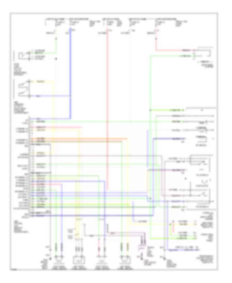
ANTI-LOCK BRAKES
Anti-lock Brake Wiring Diagrams for Subaru Impreza 1995
 https://portal-diagnostov.com/license.html
Automotive Electricians Portal FZCO
Automotive Electricians Portal FZCO
https://portal-diagnostov.com/license.html
https://portal-diagnostov.com/license.html
Automotive Electricians Portal FZCO
Automotive Electricians Portal FZCO
List of elements for Anti-lock Brake Wiring Diagrams for Subaru Impreza 1995:
- (1995 1.8l)
- (1995 2.2l, all 1996)
- (top of brake pedal support)
- (w/cruise)
- 13
- Abs check (below left side of i/p)
- Abs control unit (rear of engine compartment)
- Abs g sensor (mt only) (right rear of engine compartment)
- Abs ind
- B34
- Check conn (left kick panel)
- Chk conn
- F18
- F36
- F43
- Fuse 12 20a
- Fuse 15 10a
- Fuse 18 10a
- Fuse 19 20a
- G sensr
- G102 (left shock tower)
- G109 (right radiator support)
- G300 (below left front seat)
- Gnd
- Hot at all times
- Hot in on or start
- Hydraulic unit (right front fender)
- I17
- I18
- Instrument cluster
- Left front wheel sensor
- Left rear wheel sensor
- Lf abs sol
- Lf sensr (hi)
- Lf sensr (lo)
- Lf sol
- Lr sensr (hi)
- Lr sensr (lo)
- Lr sol
- Main fuse box
- Motor mon
- Motor relay
- Motor rly
- Pnk
- Pump motor
- R abs sol
- Relay and fuse box
- Relay coil
- Rf abs sol
- Rf sensr (hi)
- Rf sensr (lo)
- Rf sol
- Right front wheel sensor
- Right rear wheel sensor
- Rr sensr (hi)
- Rr sensr (lo)
- Sbf-6 45a
- Shield j/c (left kick panel)
- Stop
- Stop lamp switch
- Transmission control module (behind left side of i/p)
- Valve pwr mon
- Valve relay
- Valve rly
- Warn
- With awd
- With fwd
 Čeština
 Dansk
Dansk Deutsch
 Ελληνικά
 English
 English
 Español
 Suomi
Suomi Français
 Français
 עברית
עברית Hrvatski
 Magyar
 Italiano
 한국어
한국어 Nederlands
 Polski
 Português
 Português
 Română
 Русский
 Slovenčina
 Slovenščina
 Svenska
 Türkçe
 中文 (中国)
 日本語
日本語
