ENGINE PERFORMANCE
2.4L VIN 1
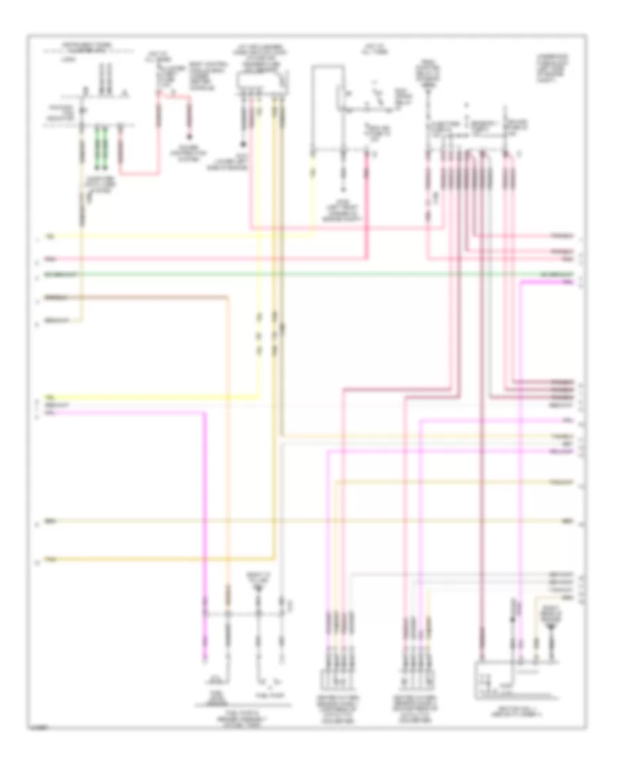
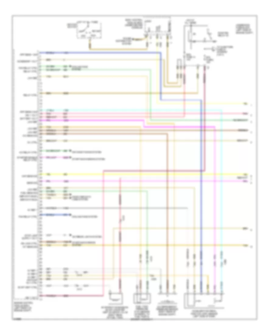
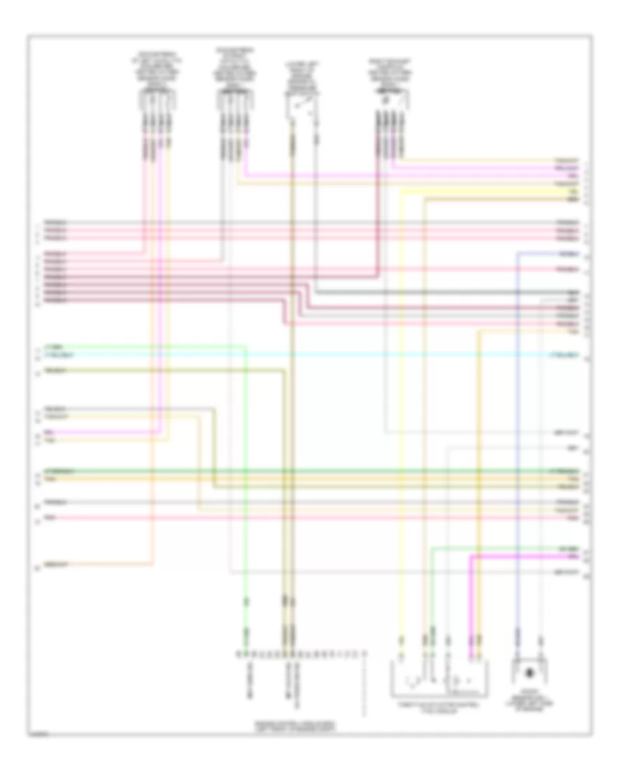
2.4L VIN 1, Engine Performance Wiring Diagram (1 of 5) for Chevrolet Malibu LT 2011
 https://portal-diagnostov.com/license.html
Automotive Electricians Portal FZCO
Automotive Electricians Portal FZCO
https://portal-diagnostov.com/license.html
https://portal-diagnostov.com/license.html
Automotive Electricians Portal FZCO
Automotive Electricians Portal FZCO
List of elements for 2.4L VIN 1, Engine Performance Wiring Diagram (1 of 5) for Chevrolet Malibu LT 2011:
- 5v ref 1
- 5v ref 2
- A/c refrigerant pressure sensor (right rear of engine compt)
- A/c relay ctrl
- A/c sens sig
- Acc
- Acc vol
- Accelerator pedal position (app) sensor (left side of dash)
- Accessory volt
- Air conditioning system
- Air pump rly ctrl
- App sens 1 sig
- App sens 2 sig
- Battery volt
- Body control logic module (bcm) (under center console)
- Computer data lines system
- Cooling fans system
- Ctrl coil
- D12
- Ecm fuse 13 10a
- Engine control module (ecm) (left front of engine compt)
- Etc fuse 2 15a
- Evap vent ctrl
- Evaporative emission (evap) canister vent solenoid valve (right rear of fuel tank)
- Exterior lights system
- Fan relay ctrl
- Fuel sens sig
- Fuel tank pressure (ftp) sensor (integral to fuel pump & sender assembly)
- Hot at all times
- Iat sens sig
- Ign 1 volt
- Ign lock ctrl
- Ignition switch
- Low ref
- Maf sens sig
- Mil ctrl
- Off
- Pnk
- Power distribution system
- Pwr/trn relay 33
- Relay ctrl
- Run
- Sens sig
- Ser data bus+
- Ser data bus-
- Start
- Starter enable relay ctrl
- Starting/charging system
- Tan
- Tan c
- Tan e
- To injectors fuse 44 (diagram 2 of 4)
- Underhood fuse block (left side of engine compt)
- X206
- X413
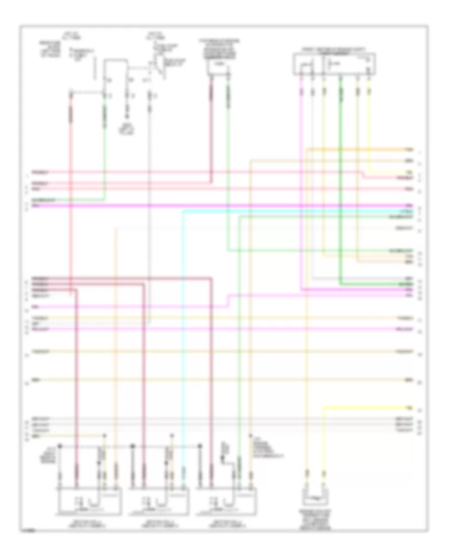
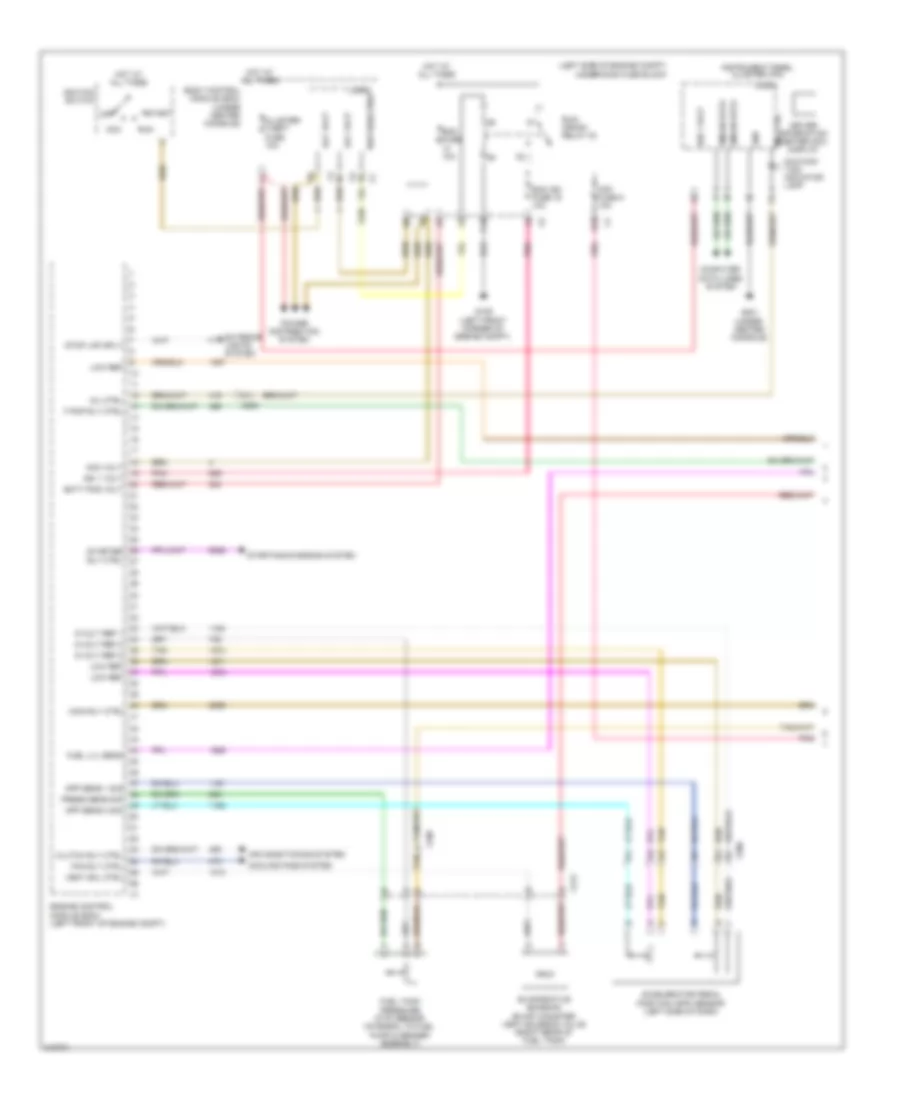
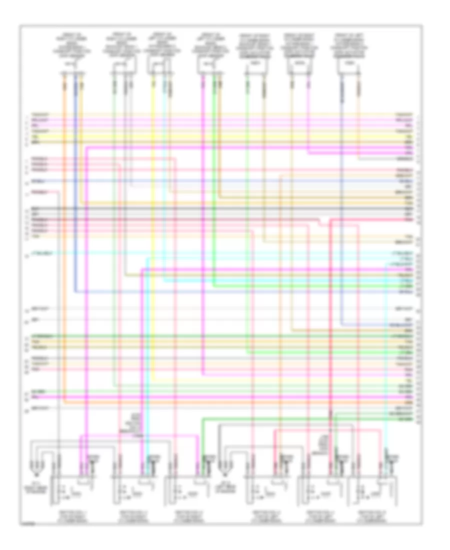
2.4L VIN 1, Engine Performance Wiring Diagram (2 of 5) for Chevrolet Malibu LT 2011
 https://portal-diagnostov.com/license.html
Automotive Electricians Portal FZCO
Automotive Electricians Portal FZCO
https://portal-diagnostov.com/license.html
https://portal-diagnostov.com/license.html
Automotive Electricians Portal FZCO
Automotive Electricians Portal FZCOList of elements for 2.4L VIN 1, Engine Performance Wiring Diagram (2 of 5) for Chevrolet Malibu LT 2011:
- (at air cleaner) mass air flow (maf)/ intake air temperature (iat) sensor
- (right "c" pillar) g301
- (right rear of engine) g110
- A10
- A11
- B11
- Body control module (bcm) (under center console)
- C10
- C11
- Cluster/ theft fuse 10a
- Computer data lines system
- D11
- E11
- Ecm ign fuse 16 10a
- Emission 1 fuse 6 10a
- From pwr/trn relay 33 (diagram 1 of 4)
- Fuel level sensor
- Fuel pump
- Fuel pump & sender assembly (in fuel tank)
- G107 (lower left side of engine)
- G109 (left front corner of engine compt)
- Gmlan data
- Heated oxygen sensor (ho2s) 1 (upstream of catalytic converter)
- Heated oxygen sensor (ho2s) 2 (downstream of catalytic converter)
- Hot at all times
- Ign
- Ign mod fuse 43 15a
- Ignition coil 1 (above cylinder 1)
- Injectors fuse 44 10a
- Instrument panel cluster (ipc)
- Logic
- Malfunc- tion indicator
- Nca
- Plug spark
- Pnk
- Power distribution system
- Run/ crank relay
- Tan
- Underhood fuse block (left side of engine compt)
- X108
- X130
- X206
- X413
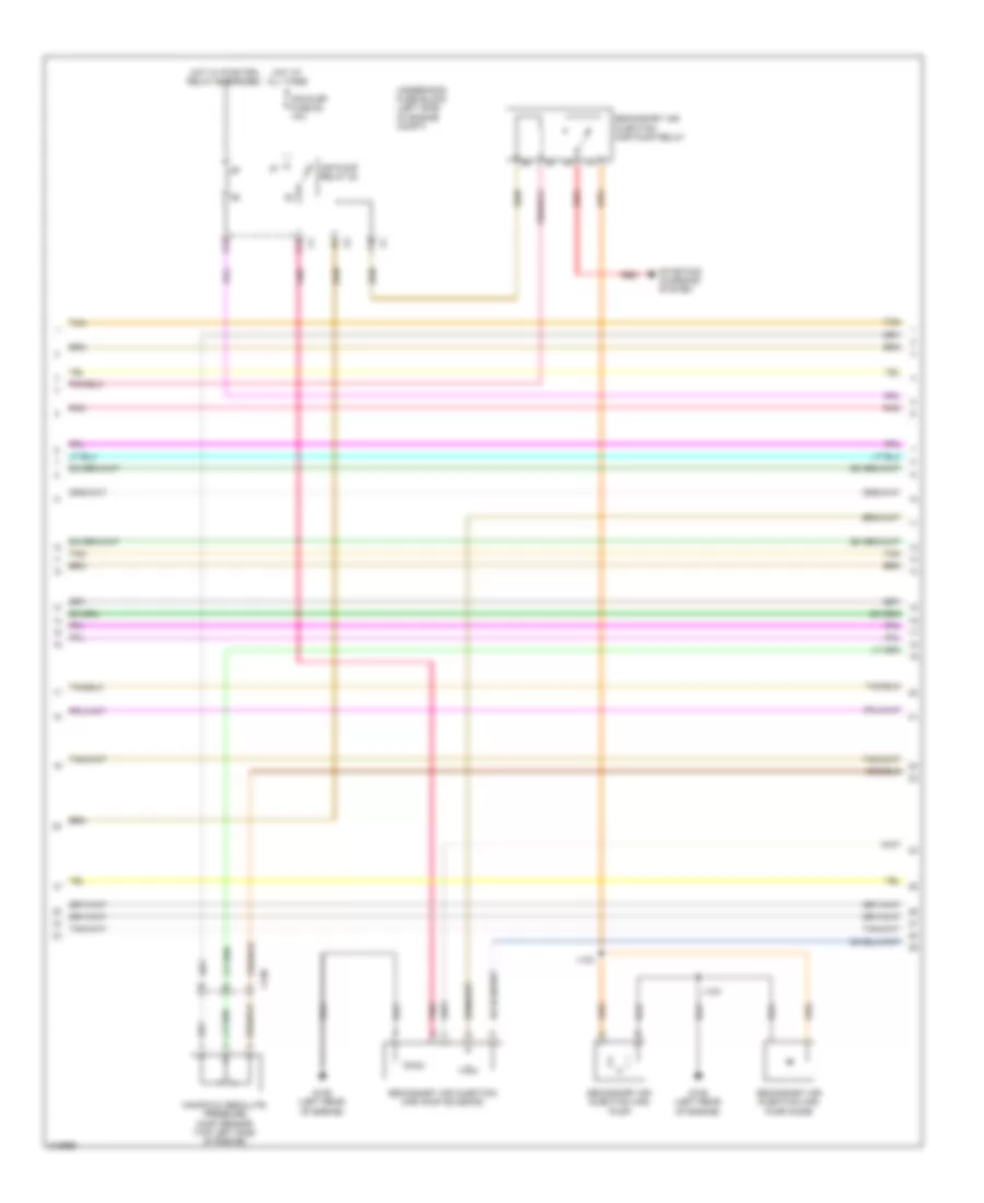
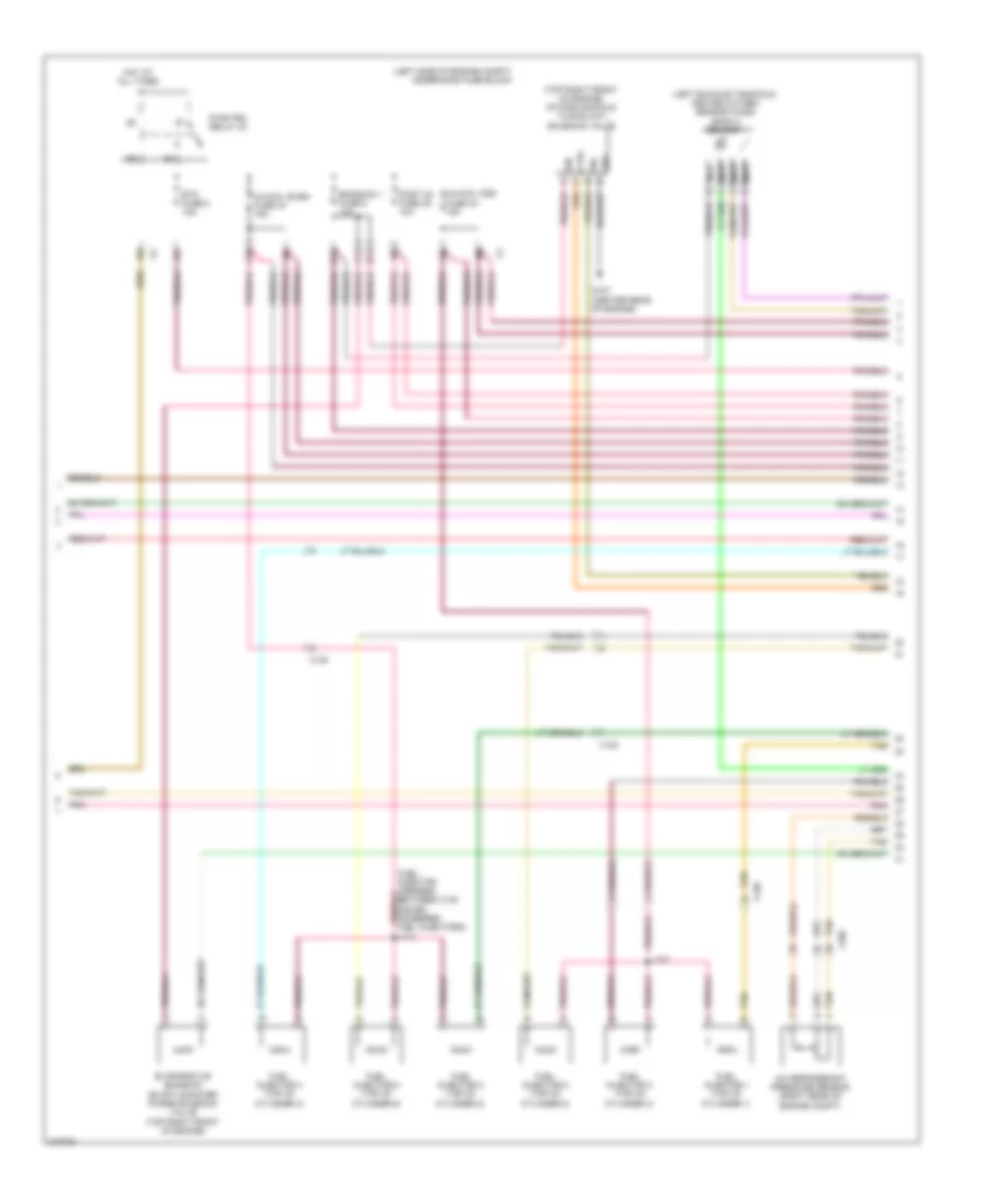
2.4L VIN 1, Engine Performance Wiring Diagram (3 of 5) for Chevrolet Malibu LT 2011
 https://portal-diagnostov.com/license.html
Automotive Electricians Portal FZCO
Automotive Electricians Portal FZCO
https://portal-diagnostov.com/license.html
https://portal-diagnostov.com/license.html
Automotive Electricians Portal FZCO
Automotive Electricians Portal FZCOList of elements for 2.4L VIN 1, Engine Performance Wiring Diagram (3 of 5) for Chevrolet Malibu LT 2011:
- (front center of engine compt) throttle body
- (top rear of engine) evaporative emission (evap) canister purge solenoid valve
- A10
- Emission 2 fuse 5 10a
- Engine coolant temperature (ect) sensor (lower right rear of engine)
- Fuel pump fuse 25 15a
- Fuel/pump relay 37
- G110 (right rear of engine)
- G302 (left "c" pillar)
- Hot at all times
- Ignition coil 2 (above cylinder 2)
- Ignition coil 3 (above cylinder 3)
- Ignition coil 4 (above cylinder 4)
- J121 (engine harness, 40 mm from main breakout)
- Nca
- Plug spark
- Pnk
- Rear fuse block (left side of trunk)
- Tan
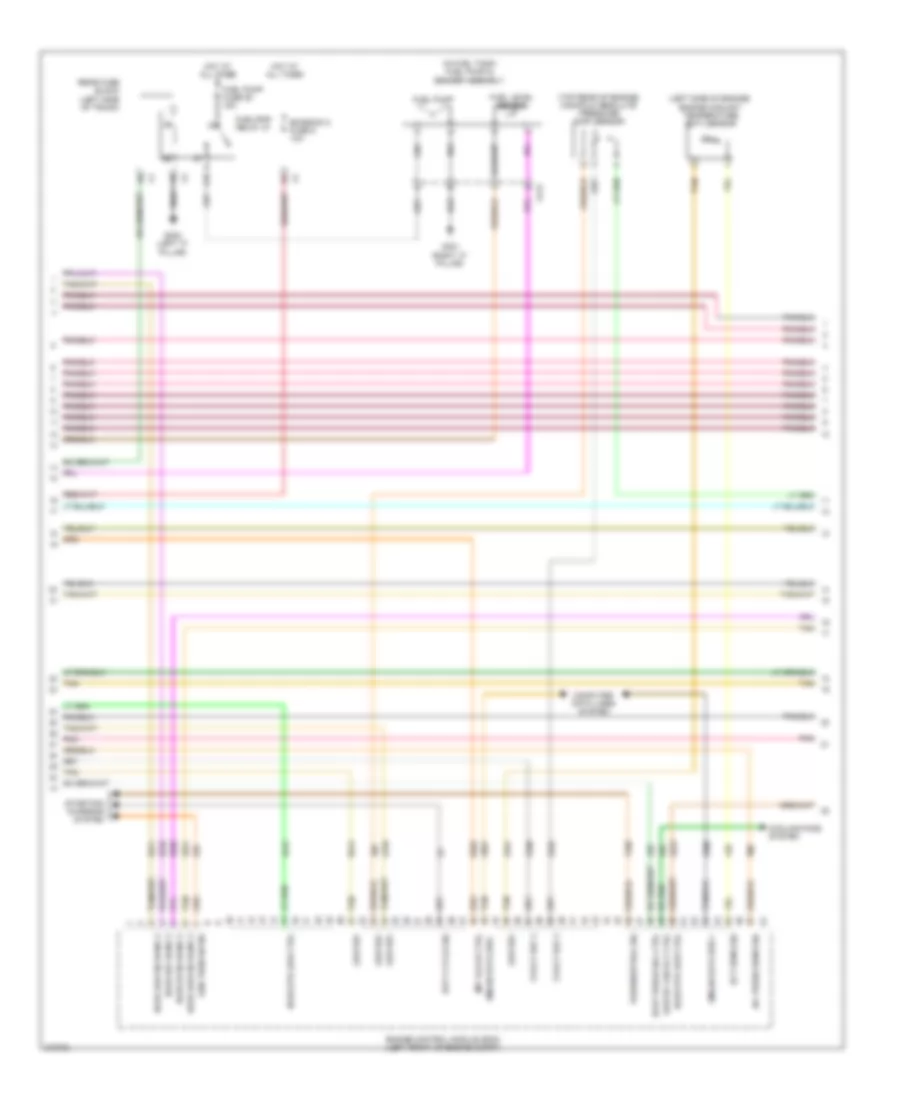
2.4L VIN 1, Engine Performance Wiring Diagram (4 of 5) for Chevrolet Malibu LT 2011
 https://portal-diagnostov.com/license.html
Automotive Electricians Portal FZCO
Automotive Electricians Portal FZCO
https://portal-diagnostov.com/license.html
https://portal-diagnostov.com/license.html
Automotive Electricians Portal FZCO
Automotive Electricians Portal FZCOList of elements for 2.4L VIN 1, Engine Performance Wiring Diagram (4 of 5) for Chevrolet Malibu LT 2011:
- A12
- Air pump fuse 52 10a
- Air pump relay 53
- C12
- F10
- G106 (left rear of engine)
- Hot at all times
- Hot w/ pwr/trn relay energized
- J123
- J124
- Manifold absolute pressure (map) sensor (top left side of engine)
- Pnk
- Red
- Secondary air injection (air) pump
- Secondary air injection (air) pump diode
- Secondary air injection (air) pump relay
- Secondary air injection (air) pump solenoid
- Starting/ charging system
- Tan
- Underhood fuse block (left side of engine compt)
- X130
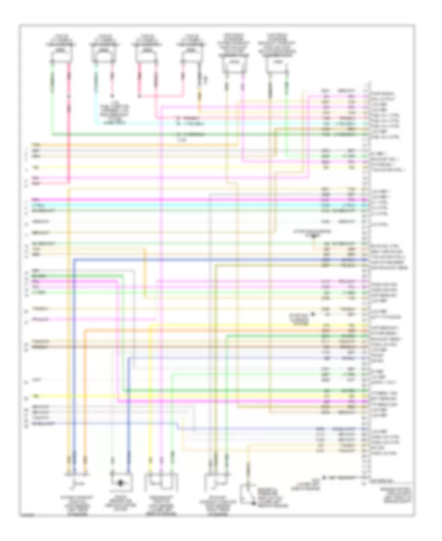
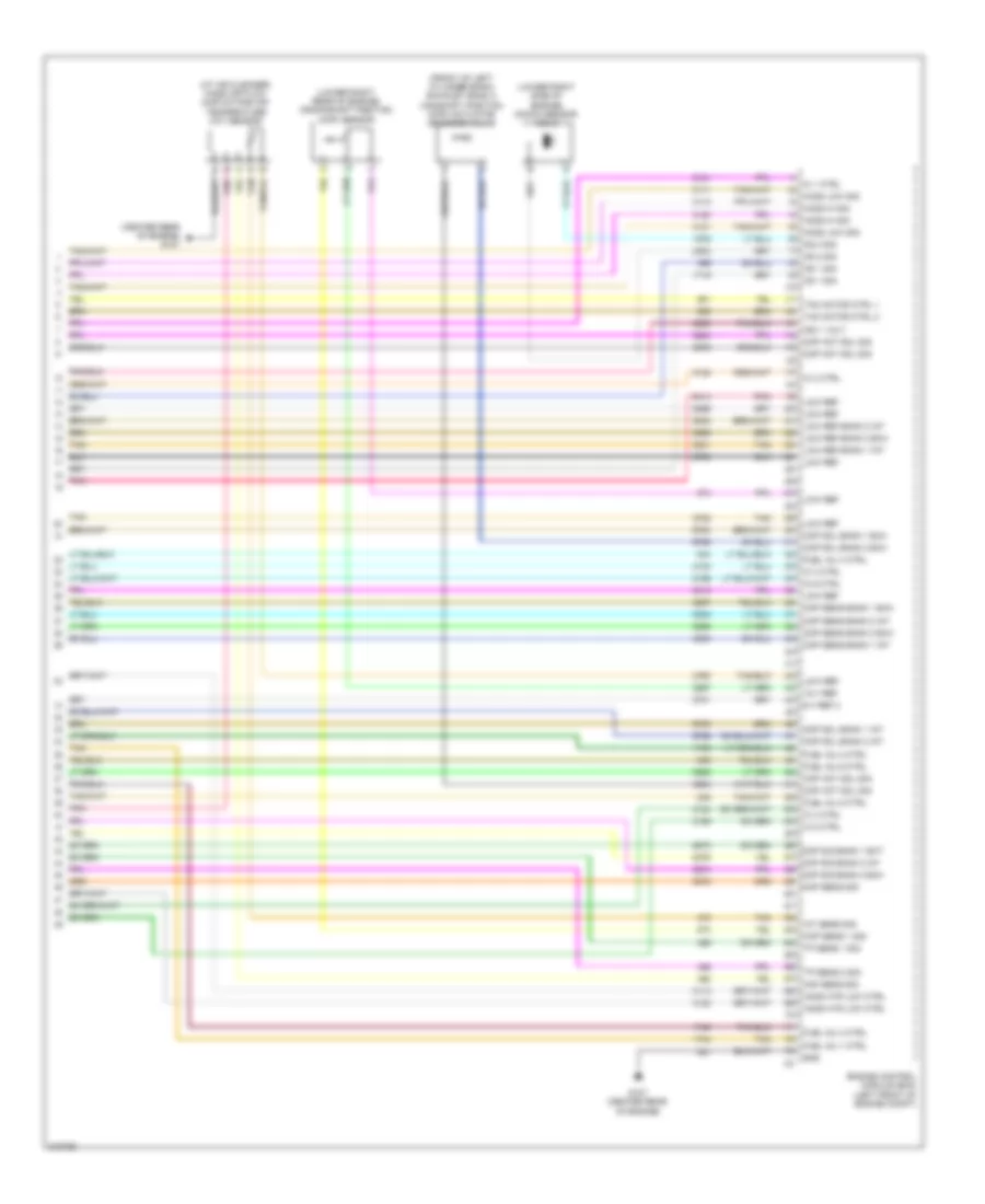
2.4L VIN 1, Engine Performance Wiring Diagram (5 of 5) for Chevrolet Malibu LT 2011
 https://portal-diagnostov.com/license.html
Automotive Electricians Portal FZCO
Automotive Electricians Portal FZCO
https://portal-diagnostov.com/license.html
https://portal-diagnostov.com/license.html
Automotive Electricians Portal FZCO
Automotive Electricians Portal FZCOList of elements for 2.4L VIN 1, Engine Performance Wiring Diagram (5 of 5) for Chevrolet Malibu LT 2011:
- (top front of engine) exhaust camshaft position (cmp) actuator solenoid solenoid valve
- (top front of engine) intake camshaft position (cmp) actuator solenoid valve
- (top of cylinder 1) fuel injector 1
- (top of cylinder 2) fuel injector 2
- (top of cylinder 3) fuel injector 3
- (top of cylinder 4) fuel injector 4
- 12v ref
- 5v ref
- 5v ref 1
- Ckp sens sig 1
- Cmp exhaust sens
- Cmp intake sens
- Coil output
- Crankshaft position (ckp) sensor (lower left rear of engine)
- Duty cycle sig
- Ect sens sig
- Engine control module (ecm) (left front of engine compt)
- Engine oil pressure (eop) switch (lower left rear of engine)
- Evap sol ctrl
- Exhaust camshaft position (cmp) sensor (right rear of engine)
- Exhaust sens 1
- Exhaust sol 1
- Fuel inj 1 ctrl
- Fuel inj 2 ctrl
- Fuel inj 3 ctrl
- Fuel inj 4 ctrl
- G107 (lower left side of engine)
- Gen turn on sig
- Ho2s high sig
- Ho2s low ctrl
- Ho2s low sig
- Ic 1 ctrl
- Ic 2 ctrl
- Ic 3 ctrl
- Ic 4 ctrl
- Intake camshaft position (cmp) sensor (left rear of engine)
- Intake sens 1
- Intake sol 1
- J130 (fuel injector harness, 4 cm from breakout to fuel injector 2)
- Knock sensor (ks) (above starter motor)
- Ks sig
- Low ref
- Low ref 1
- Map sens sig
- Pnk
- Pump signal
- Sig ground
- Starting/ charging system
- Starting/charging system
- Sw sig
- Tac motor ctrl 1
- Tac motor ctrl 2
- Tan
- Tp sens 1 sig
- Tp sens 2 sig
- X130
2.4L VIN U
2.4L VIN U, Engine Performance Wiring Diagram (1 of 5) for Chevrolet Malibu LT 2011
 https://portal-diagnostov.com/license.html
Automotive Electricians Portal FZCO
Automotive Electricians Portal FZCO
https://portal-diagnostov.com/license.html
https://portal-diagnostov.com/license.html
Automotive Electricians Portal FZCO
Automotive Electricians Portal FZCOList of elements for 2.4L VIN U, Engine Performance Wiring Diagram (1 of 5) for Chevrolet Malibu LT 2011:
- 5v ref 1
- 5v ref 2
- A/c refrigerant pressure sensor (right rear of engine compt)
- A/c relay ctrl
- A/c sens sig
- Acc
- Acc vol
- Accelerator pedal position (app) sensor (left side of dash)
- Accessory volt
- Air conditioning system
- Air pump rly ctrl
- App sens 1 sig
- App sens 2 sig
- Battery volt
- Body control logic module (bcm) (under center console)
- Computer data lines system
- Cooling fans system
- Ctrl coil
- D12
- Ecm fuse 13 10a
- Engine control module (ecm) (left front of engine compt)
- Etc fuse 2 15a
- Evap vent ctrl
- Evaporative emission (evap) canister vent solenoid valve (right rear of fuel tank)
- Exterior lights system
- Fan relay ctrl
- Fuel sens sig
- Fuel tank pressure (ftp) sensor (integral to fuel pump & sender assembly)
- Hot at all times
- Iat sens sig
- Ign 1 volt
- Ign lock ctrl
- Ignition switch
- Low ref
- Maf sens sig
- Mil ctrl
- Off
- Pnk
- Power distribution system
- Pwr/trn relay 33
- Relay ctrl
- Run
- Sens sig
- Ser data bus+
- Ser data bus-
- Start
- Starter enable relay ctrl
- Starting/charging system
- Tan
- Tan c
- Tan e
- To injectors fuse 44 (diagram 2 of 4)
- Underhood fuse block (left side of engine compt)
- X206
- X413
2.4L VIN U, Engine Performance Wiring Diagram (2 of 5) for Chevrolet Malibu LT 2011
 https://portal-diagnostov.com/license.html
Automotive Electricians Portal FZCO
Automotive Electricians Portal FZCO
https://portal-diagnostov.com/license.html
https://portal-diagnostov.com/license.html
Automotive Electricians Portal FZCO
Automotive Electricians Portal FZCOList of elements for 2.4L VIN U, Engine Performance Wiring Diagram (2 of 5) for Chevrolet Malibu LT 2011:
- (at air cleaner) mass air flow (maf)/ intake air temperature (iat) sensor
- (right "c" pillar) g301
- (right rear of engine) g110
- A10
- A11
- B11
- Body control module (bcm) (under center console)
- C10
- C11
- Cluster/ theft fuse 10a
- Computer data lines system
- D11
- E11
- Ecm ign fuse 16 10a
- Emission 1 fuse 6 10a
- From pwr/trn relay 33 (diagram 1 of 4)
- Fuel level sensor
- Fuel pump
- Fuel pump & sender assembly (in fuel tank)
- G107 (lower left side of engine)
- G109 (left front corner of engine compt)
- Gmlan data
- Heated oxygen sensor (ho2s) 1 (upstream of catalytic converter)
- Heated oxygen sensor (ho2s) 2 (downstream of catalytic converter)
- Hot at all times
- Ign
- Ign mod fuse 43 15a
- Ignition coil 1 (above cylinder 1)
- Injectors fuse 44 10a
- Instrument panel cluster (ipc)
- Logic
- Malfunc- tion indicator
- Nca
- Plug spark
- Pnk
- Power distribution system
- Run/ crank relay
- Tan
- Underhood fuse block (left side of engine compt)
- X108
- X130
- X206
- X413
2.4L VIN U, Engine Performance Wiring Diagram (3 of 5) for Chevrolet Malibu LT 2011
 https://portal-diagnostov.com/license.html
Automotive Electricians Portal FZCO
Automotive Electricians Portal FZCO
https://portal-diagnostov.com/license.html
https://portal-diagnostov.com/license.html
Automotive Electricians Portal FZCO
Automotive Electricians Portal FZCOList of elements for 2.4L VIN U, Engine Performance Wiring Diagram (3 of 5) for Chevrolet Malibu LT 2011:
- (front center of engine compt) throttle body
- (top rear of engine) evaporative emission (evap) canister purge solenoid valve
- A10
- Emission 2 fuse 5 10a
- Engine coolant temperature (ect) sensor (lower right rear of engine)
- Fuel pump fuse 25 15a
- Fuel/pump relay 37
- G110 (right rear of engine)
- G302 (left "c" pillar)
- Hot at all times
- Ignition coil 2 (above cylinder 2)
- Ignition coil 3 (above cylinder 3)
- Ignition coil 4 (above cylinder 4)
- J121 (engine harness, 40 mm from main breakout)
- Nca
- Plug spark
- Pnk
- Rear fuse block (left side of trunk)
- Tan
2.4L VIN U, Engine Performance Wiring Diagram (4 of 5) for Chevrolet Malibu LT 2011
 https://portal-diagnostov.com/license.html
Automotive Electricians Portal FZCO
Automotive Electricians Portal FZCO
https://portal-diagnostov.com/license.html
https://portal-diagnostov.com/license.html
Automotive Electricians Portal FZCO
Automotive Electricians Portal FZCOList of elements for 2.4L VIN U, Engine Performance Wiring Diagram (4 of 5) for Chevrolet Malibu LT 2011:
- A12
- Air pump fuse 52 10a
- Air pump relay 53
- C12
- F10
- G106 (left rear of engine)
- Hot at all times
- Hot w/ pwr/trn relay energized
- J123
- J124
- Manifold absolute pressure (map) sensor (top left side of engine)
- Pnk
- Red
- Secondary air injection (air) pump
- Secondary air injection (air) pump diode
- Secondary air injection (air) pump relay
- Secondary air injection (air) pump solenoid
- Starting/ charging system
- Tan
- Underhood fuse block (left side of engine compt)
- X130
2.4L VIN U, Engine Performance Wiring Diagram (5 of 5) for Chevrolet Malibu LT 2011
 https://portal-diagnostov.com/license.html
Automotive Electricians Portal FZCO
Automotive Electricians Portal FZCO
https://portal-diagnostov.com/license.html
https://portal-diagnostov.com/license.html
Automotive Electricians Portal FZCO
Automotive Electricians Portal FZCOList of elements for 2.4L VIN U, Engine Performance Wiring Diagram (5 of 5) for Chevrolet Malibu LT 2011:
- (top front of engine) exhaust camshaft position (cmp) actuator solenoid solenoid valve
- (top front of engine) intake camshaft position (cmp) actuator solenoid valve
- (top of cylinder 1) fuel injector 1
- (top of cylinder 2) fuel injector 2
- (top of cylinder 3) fuel injector 3
- (top of cylinder 4) fuel injector 4
- 12v ref
- 5v ref
- 5v ref 1
- Ckp sens sig 1
- Cmp exhaust sens
- Cmp intake sens
- Coil output
- Crankshaft position (ckp) sensor (lower left rear of engine)
- Duty cycle sig
- Ect sens sig
- Engine control module (ecm) (left front of engine compt)
- Engine oil pressure (eop) switch (lower left rear of engine)
- Evap sol ctrl
- Exhaust camshaft position (cmp) sensor (right rear of engine)
- Exhaust sens 1
- Exhaust sol 1
- Fuel inj 1 ctrl
- Fuel inj 2 ctrl
- Fuel inj 3 ctrl
- Fuel inj 4 ctrl
- G107 (lower left side of engine)
- Gen turn on sig
- Ho2s high sig
- Ho2s low ctrl
- Ho2s low sig
- Ic 1 ctrl
- Ic 2 ctrl
- Ic 3 ctrl
- Ic 4 ctrl
- Intake camshaft position (cmp) sensor (left rear of engine)
- Intake sens 1
- Intake sol 1
- J130 (fuel injector harness, 4 cm from breakout to fuel injector 2)
- Knock sensor (ks) (above starter motor)
- Ks sig
- Low ref
- Low ref 1
- Map sens sig
- Pnk
- Pump signal
- Sig ground
- Starting/ charging system
- Starting/charging system
- Sw sig
- Tac motor ctrl 1
- Tac motor ctrl 2
- Tan
- Tp sens 1 sig
- Tp sens 2 sig
- X130
3.6L VIN 7
3.6L VIN 7, Engine Performance Wiring Diagram (1 of 6) for Chevrolet Malibu LT 2011
 https://portal-diagnostov.com/license.html
Automotive Electricians Portal FZCO
Automotive Electricians Portal FZCO
https://portal-diagnostov.com/license.html
https://portal-diagnostov.com/license.html
Automotive Electricians Portal FZCO
Automotive Electricians Portal FZCOList of elements for 3.6L VIN 7, Engine Performance Wiring Diagram (1 of 6) for Chevrolet Malibu LT 2011:
- (left side of engine compt) underhood fuse block
- 5-volt ref 1
- 5-volt ref 2
- A11
- Acc
- Acc volt
- Accelerator pedal position (app) sensor (left side of dash)
- Air conditioning system
- App sens 1 sig
- App sens 2 sig
- B10
- Batt pos volt
- Body control module (bcm) (under center console)
- C10
- Cluster/ theft fuse 10a
- Clutch rly ctrl
- Computer data lines system
- Cooling fans system
- Driver information center (dic) display
- Ecm fuse 10a
- Ecm ign fuse 16 10a
- Engine control module (ecm) (left front of engine compt)
- Evaporative emission (evap) canister vent solenoid valve (right rear of fuel tank)
- Exterior lights system
- F pmp rly ctrl
- Fan rly ctrl
- Fuel lvl sens
- Fuel tank pressure (ftp) sensor (integral to fuel pump & sender assembly)
- G109 (left front corner of engine compt)
- G201 (under center console)
- Gmlan data
- Gnd
- Hot at all times
- Ign 1 volt
- Ignition switch
- Instrument panel cluster (ipc)
- Logic
- Low ref
- Maf fuse 5 10a
- Main rly ctrl
- Malfunc- tion indicator lamp
- Mil ctrl
- Off
- Pnk
- Power distribution system
- Press sens sig
- Rly coil ctrl
- Run
- Run/ crank relay 32
- Start
- Starter rly ctrl
- Starting/charging system
- Stop lmp sply
- Tan
- Vent sol ctrl
- X108
- X206
- X413
3.6L VIN 7, Engine Performance Wiring Diagram (2 of 6) for Chevrolet Malibu LT 2011
 https://portal-diagnostov.com/license.html
Automotive Electricians Portal FZCO
Automotive Electricians Portal FZCO
https://portal-diagnostov.com/license.html
https://portal-diagnostov.com/license.html
Automotive Electricians Portal FZCO
Automotive Electricians Portal FZCOList of elements for 3.6L VIN 7, Engine Performance Wiring Diagram (2 of 6) for Chevrolet Malibu LT 2011:
- (left exhaust manifold) heated oxygen sensor (ho2s) bank 2 sensor 1
- (left side of engine compt) underhood fuse block
- (top right front of engine) intake manifold tuning (imt) solenoid valve
- A/c refrigerant pressure sensor (right rear of engine compt)
- A10
- B11
- C11
- Ctrl c
- D11
- Emission 1 fuse 6 10a
- Etc fuse 2 15a
- Evaporative emission (evap) canister purge solenoid valve (top right front of engine)
- Fuel injector 1 (top of cylinder 1)
- Fuel injector 2 (top of cylinder 2)
- Fuel injector 3 (top of cylinder 3)
- Fuel injector 4 (top of cylinder 4)
- Fuel injector 5 (top of cylinder 5)
- Fuel injector 6 (top of cylinder 6)
- G107 (center rear of engine)
- Gnd b
- Hot at all times
- Ign a
- Inj/coil even fuse 44 15a
- Inj/coil odd fuse 43 15a
- J107
- J114
- Nca
- Pnk
- Post o2 fuse 45 10a
- Pwr/trn relay 33
- Sig d
- Tan
- X108
- X130
3.6L VIN 7, Engine Performance Wiring Diagram (3 of 6) for Chevrolet Malibu LT 2011
 https://portal-diagnostov.com/license.html
Automotive Electricians Portal FZCO
Automotive Electricians Portal FZCO
https://portal-diagnostov.com/license.html
https://portal-diagnostov.com/license.html
Automotive Electricians Portal FZCO
Automotive Electricians Portal FZCOList of elements for 3.6L VIN 7, Engine Performance Wiring Diagram (3 of 6) for Chevrolet Malibu LT 2011:
- (in fuel tank) fuel pump & sender assembly
- (left side of engine) engine coolant temperature (ect) sensor
- (top rear of engine) manifold absolute pressure (map) sensor
- 5-volt ref 2
- A/c press sens sig
- A10
- Computer data lines system
- Cooling fans system
- Duty cycle sig
- Ect sens sig
- Emission 2 fuse 5 10a
- Engine control module (ecm) (left front of engine compt)
- Evap purge sol ctrl
- Fuel level sensor
- Fuel pump
- Fuel pump fuse 25 15a
- Fuel/pmp relay 37
- G301 (right "c" pillar)
- G302 (left "c" pillar)
- Gen turn on sig
- Gmlan data bus +
- Gmlan data bus -
- Ho2s hi sig bank 2
- Ho2s htr low ctrl
- Ho2s low sig bank 2
- Ho2s ref bank 2
- Hot at all times
- Imt valve ctrl
- Low ref
- Low sp fan rly ctrl
- Park/neutral sig
- Pnk
- Rear fuse block (left side of trunk)
- Starting/ charging system
- Tan
- X413
3.6L VIN 7, Engine Performance Wiring Diagram (4 of 6) for Chevrolet Malibu LT 2011
 https://portal-diagnostov.com/license.html
Automotive Electricians Portal FZCO
Automotive Electricians Portal FZCO
https://portal-diagnostov.com/license.html
https://portal-diagnostov.com/license.html
Automotive Electricians Portal FZCO
Automotive Electricians Portal FZCOList of elements for 3.6L VIN 7, Engine Performance Wiring Diagram (4 of 6) for Chevrolet Malibu LT 2011:
- (downstream of left catalytic converter) heated oxygen sensor (ho2s) bank 2 sensor 2
- (downstream of right catalytic converter) heated oxygen sensor (ho2s) bank 1 sensor 2
- (lower left front of engine) engine oil pressure (eop) switch
- (right exhaust manifold) heated oxygen sensor (ho2s) bank 1 sensor 1
- Engine control module (ecm) (left front of engine compt)
- Imt valve sig
- Knock sensor (ks) 1 (lower left side of engine)
- Map sens sig
- Nca
- Oil press sw sig
- Pnk
- Tan
- Throttle actuator control (tac) module
3.6L VIN 7, Engine Performance Wiring Diagram (5 of 6) for Chevrolet Malibu LT 2011
 https://portal-diagnostov.com/license.html
Automotive Electricians Portal FZCO
Automotive Electricians Portal FZCO
https://portal-diagnostov.com/license.html
https://portal-diagnostov.com/license.html
Automotive Electricians Portal FZCO
Automotive Electricians Portal FZCOList of elements for 3.6L VIN 7, Engine Performance Wiring Diagram (5 of 6) for Chevrolet Malibu LT 2011:
- (5 cm from ignition coil 5 breakout) j198
- (front of left cylinder bank) exhaust bank 2 camshaft position (cmp) sensor
- (front of left cylinder bank) intake bank 2 camshaft position (cmp) actuator solenoid valve
- (front of left cylinder bank) intake bank 2 camshaft position (cmp) sensor
- (front of right cylinder bank) exhaust bank 1 camshaft position (cmp) actuator solenoid valve
- (front of right cylinder bank) exhaust bank 1 camshaft position (cmp) sensor
- (front of right cylinder bank) intake bank 1 camshaft position (cmp) actuator solenoid valve
- (front of right cylinder bank) intake bank 1 camshaft position (cmp) sensor
- G111 (right rear of engine)
- G113 (left rear of engine)
- Ignition coil 1 (top of right cylinder bank)
- Ignition coil 2 (top of left cylinder bank)
- Ignition coil 3 (top of right cylinder bank)
- Ignition coil 4 (top of left cylinder bank)
- Ignition coil 5 (top of right cylinder bank)
- Ignition coil 6 (top of left cylinder bank)
- J199 (5 cm from main branch)
- Nca
- Pnk
- Pnk b
- Spark plug
- Tan
3.6L VIN 7, Engine Performance Wiring Diagram (6 of 6) for Chevrolet Malibu LT 2011
 https://portal-diagnostov.com/license.html
Automotive Electricians Portal FZCO
Automotive Electricians Portal FZCO
https://portal-diagnostov.com/license.html
https://portal-diagnostov.com/license.html
Automotive Electricians Portal FZCO
Automotive Electricians Portal FZCOList of elements for 3.6L VIN 7, Engine Performance Wiring Diagram (6 of 6) for Chevrolet Malibu LT 2011:
- (at air cleaner) mass air flow (maf)/intake air temperature (iat) sensor
- (center rear of engine) g107
- (front of left cylinder bank) exhaust bank 2 camshaft position (cmp) actuator solenoid valve
- (lower right rear of engine) crankshaft position (ckp) sensor
- (lower right side of engine) knock sensor (ks) 2
- 12-v ref
- 5-v ref 2
- Ckp sens 1 sig
- Cmp act sol sig
- Cmp sens bank 1 exh
- Cmp sens bank 1 int
- Cmp sens bank 2 exh
- Cmp sens bank 2 int
- Cmp sig bank 1 ext
- Cmp sig bank 2 exh
- Cmp sig bank 2 int
- Cmp sol bank 1 exh
- Cmp sol bank 1 int
- Cmp sol bank 2 exh
- Cmp sol bank 2 int
- Engine control module (ecm) (left front of engine compt)
- Fuel inj 1 ctrl
- Fuel inj 2 ctrl
- Fuel inj 3 ctrl
- Fuel inj 4 ctrl
- Fuel inj 5 ctrl
- Fuel inj 6 ctrl
- G107 (center rear of engine)
- Gnd
- Ho2s hi sig
- Ho2s htr low ctrl
- Ho2s low sig
- Iat sens sig
- Ic 1 ctrl
- Ic 2 ctrl
- Ic 3 ctrl
- Ic 4 ctrl
- Ic 5 ctrl
- Ic 6 ctrl
- Ign 1 volt
- Ks 1 sig
- Ks 2 sig
- Low ref
- Low ref bank 1 int
- Low ref bank 2 exh
- Low ref bank 2 int
- Maf sens sig
- Map sens sig
- Pnk
- Tac motor ctrl 1
- Tac motor ctrl 2
- Tan
- Tp sens 1 sig
- Tp sens 2 sig

 Čeština
 Dansk
Dansk Deutsch
 Ελληνικά
 English
 English
 Español
 Suomi
Suomi Français
 Français
 עברית
עברית Hrvatski
 Magyar
 Italiano
 한국어
한국어 Nederlands
 Polski
 Português
 Português
 Română
 Русский
 Slovenčina
 Slovenščina
 Svenska
 Türkçe
 中文 (中国)
