ENGINE PERFORMANCE
3.0L TURBO
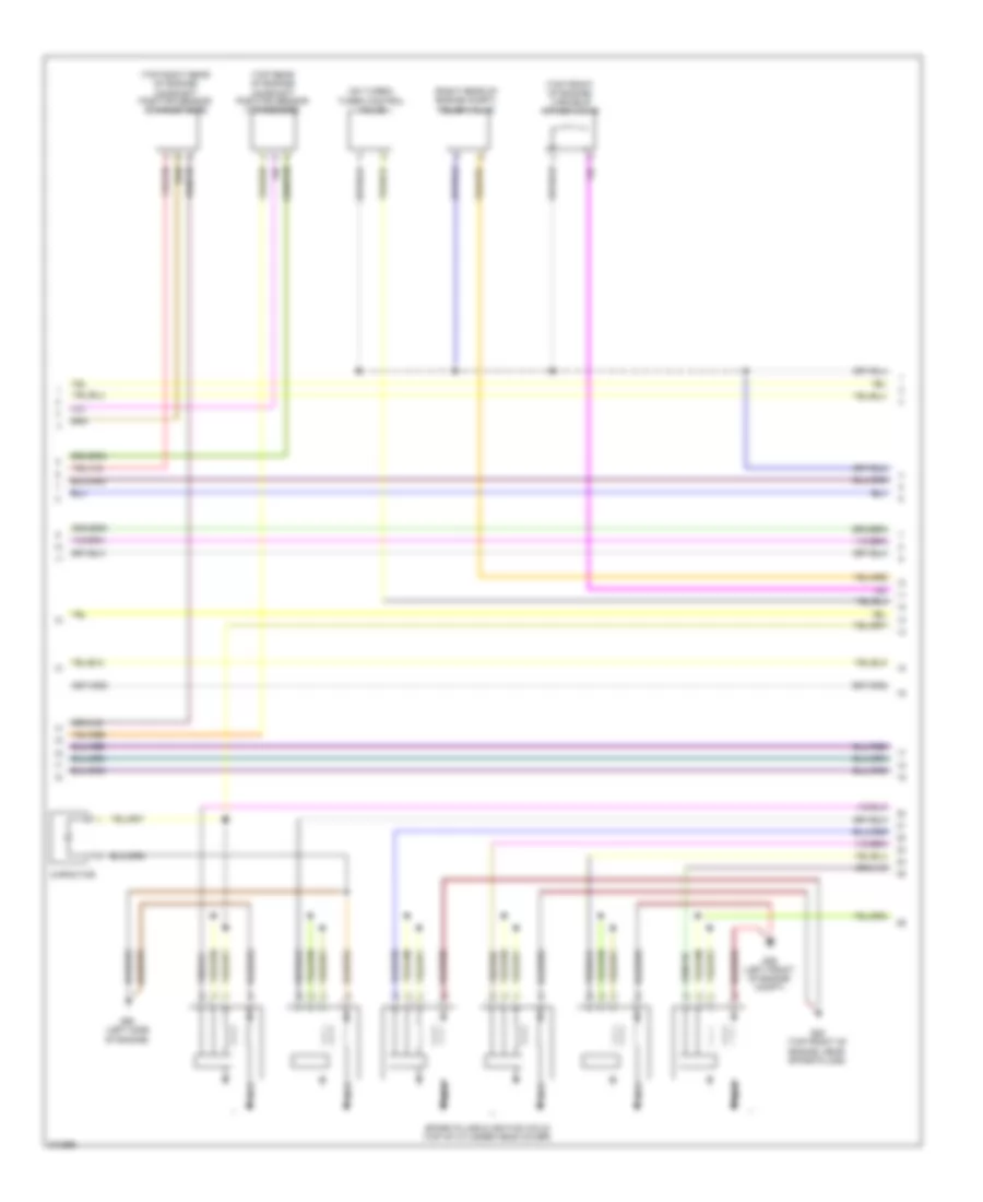
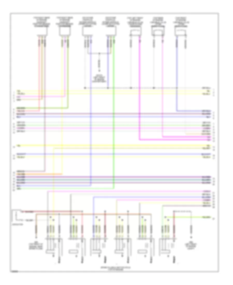
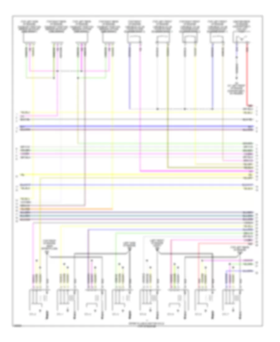
3.0L Turbo, Engine Performance Wiring Diagram (1 of 5) for Volvo S80 T-6 2009
 https://portal-diagnostov.com/license.html
Automotive Electricians Portal FZCO
Automotive Electricians Portal FZCO
https://portal-diagnostov.com/license.html
https://portal-diagnostov.com/license.html
Automotive Electricians Portal FZCO
Automotive Electricians Portal FZCO
List of elements for 3.0L Turbo, Engine Performance Wiring Diagram (1 of 5) for Volvo S80 T-6 2009:
- (in left exhaust manifold) front oxygen sensor (bank 1)
- (in right exhaust manifold) front oxygen sensor (bank 2)
- (left front of engine) coolant temperature sensor
- (left rear of engine) evap valve
- (lower rear of engine) impulse sensor
- A10
- A11
- A12
- A13
- A14
- A15
- A16
- A17
- A18
- A19
- A20
- A21
- A22
- A23
- A24
- A25
- A26
- A27
- A28
- A29
- A30
- A31
- A32
- A33
- A34
- A35
- A36
- A37
- A38
- A39
- A40
- A41
- A42
- A43
- A44
- A45
- A46
- A47
- A48
- A49
- A50
- Engine control module (ecm) (left rear of engine compt)
- Front knock sensor (top front of engine)
- Fuel pressure & temperature sensor (left front of engine)
- Intake manifold pressure & temperature sensor (left front of engine)
- Intake manifold pressure sensor (in intake manifold)
- Nca
- Oil level sensor (in oil cooler)
- Rear knock sensor (top rear of engine)
3.0L Turbo, Engine Performance Wiring Diagram (2 of 5) for Volvo S80 T-6 2009
 https://portal-diagnostov.com/license.html
Automotive Electricians Portal FZCO
Automotive Electricians Portal FZCO
https://portal-diagnostov.com/license.html
https://portal-diagnostov.com/license.html
Automotive Electricians Portal FZCO
Automotive Electricians Portal FZCOList of elements for 3.0L Turbo, Engine Performance Wiring Diagram (2 of 5) for Volvo S80 T-6 2009:
- (on turbo) turbo control valve
- (right rear of engine compt) relief valve
- (top front of engine) variable intake valve
- (top rear of engine) camshaft position sensor (intake side)
- (top right rear of engine) camshaft position sensor (exhaust side)
- Capacitor
- G88 (top front of engine, near spark plugs)
- G89 (left front of engine compt)
- G90 (left side of engine)
- Nca
- Spark plugs & ignition coils (top of cylinder head cover)
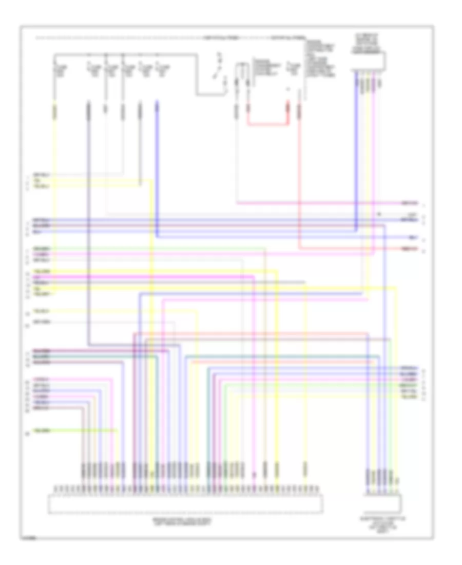
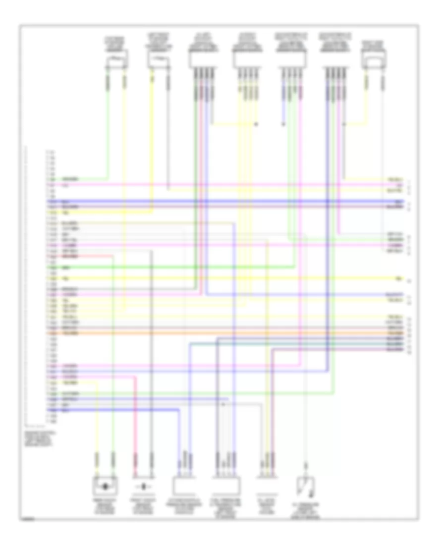
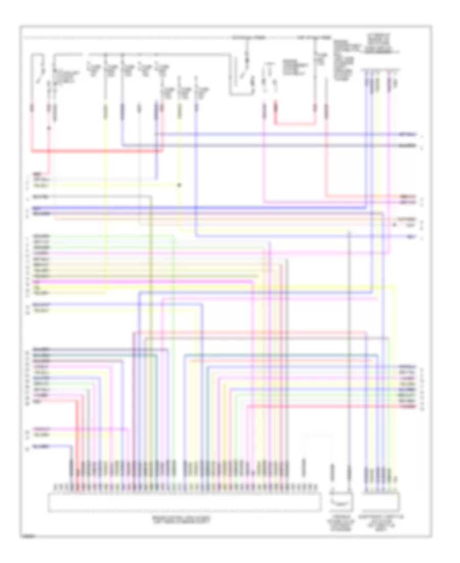
3.0L Turbo, Engine Performance Wiring Diagram (3 of 5) for Volvo S80 T-6 2009
 https://portal-diagnostov.com/license.html
Automotive Electricians Portal FZCO
Automotive Electricians Portal FZCO
https://portal-diagnostov.com/license.html
https://portal-diagnostov.com/license.html
Automotive Electricians Portal FZCO
Automotive Electricians Portal FZCOList of elements for 3.0L Turbo, Engine Performance Wiring Diagram (3 of 5) for Volvo S80 T-6 2009:
- (at rear of engine, on air intake) mass airflow (maf) sensor
- A51
- A52
- A53
- A54
- A55
- A56
- A57
- A58
- A59
- A60
- A61
- A62
- A63
- A64
- A65
- A66
- A67
- A68
- A69
- A70
- A71
- A72
- A73
- A74
- A75
- A76
- A77
- A78
- A79
- A80
- A81
- A82
- A83
- A84
- A85
- A86
- A87
- A88
- A89
- A90
- A91
- A92
- A93
- A94
- A95
- A96
- A97
- Electronic throttle actuator (on throttle body)
- Engine compartment distribution box (left side of engine compartment, forward of strut tower)
- Engine control module (ecm) (left rear of engine compt)
- Engine management system main relay
- Fuse b30 10a
- Fuse b35 20a
- Fuse b36 10a
- Fuse b37 15a
- Fuse b38 10a
- Fuse b39 15a
- Fuse b41 5a
- Hot at all times
- Red
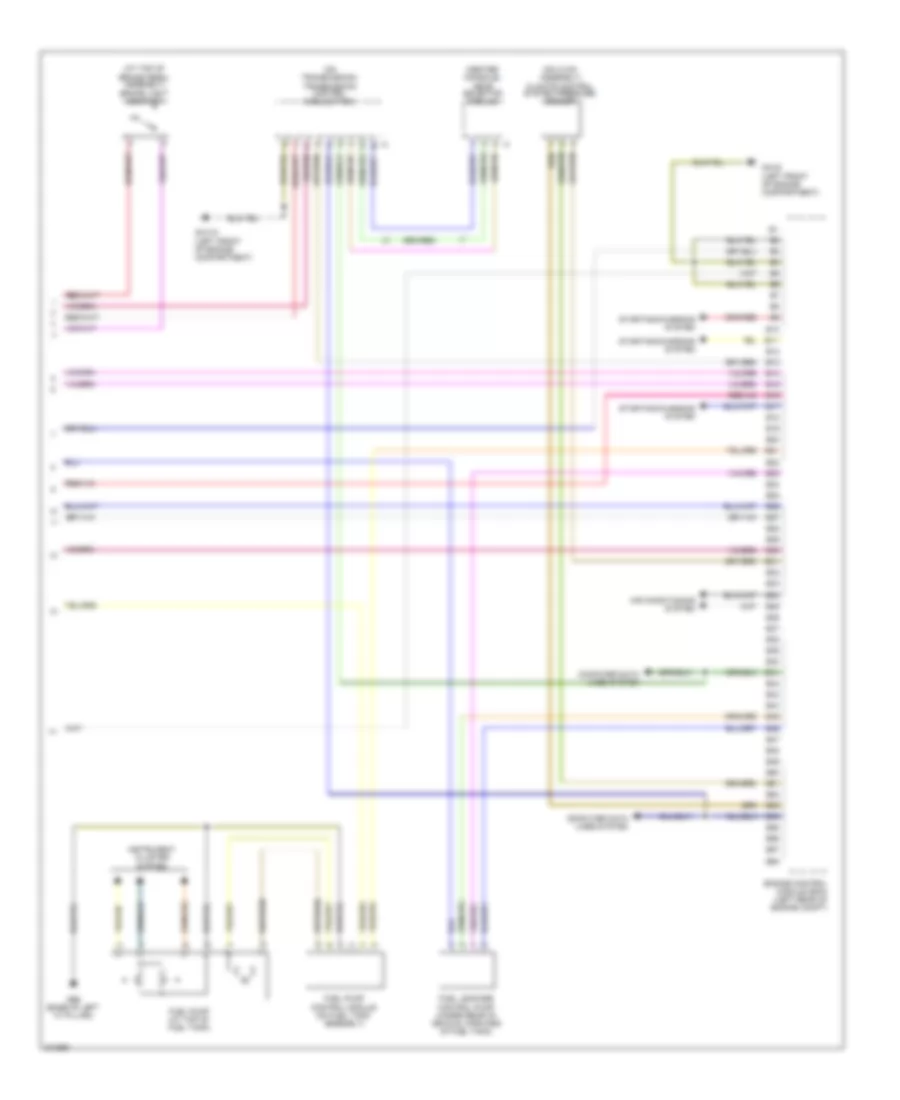
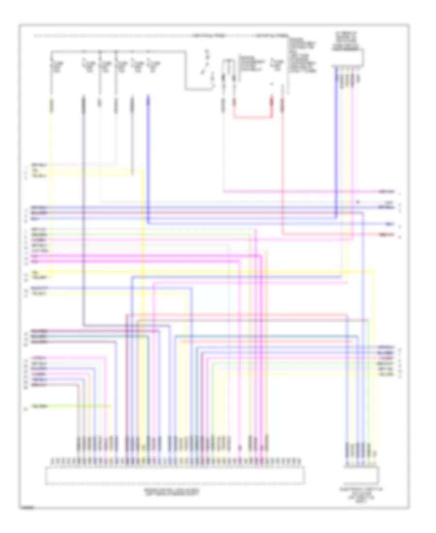
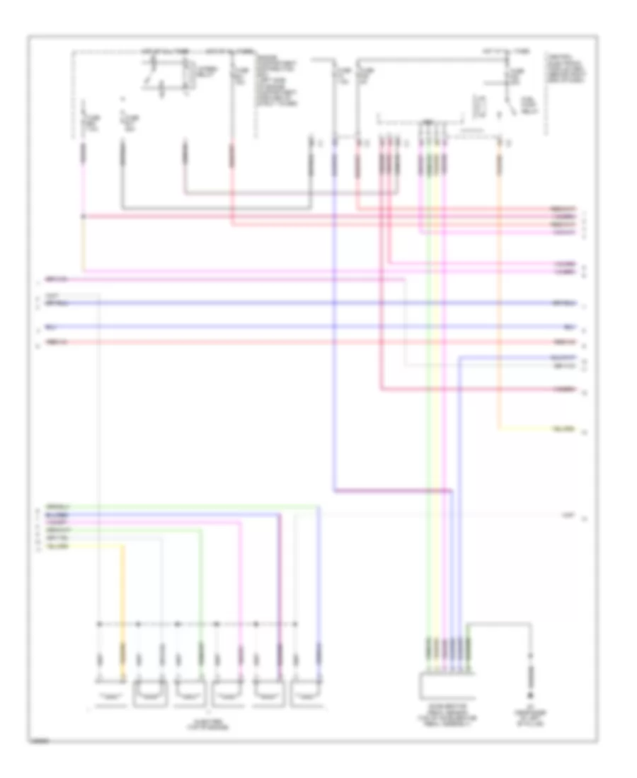
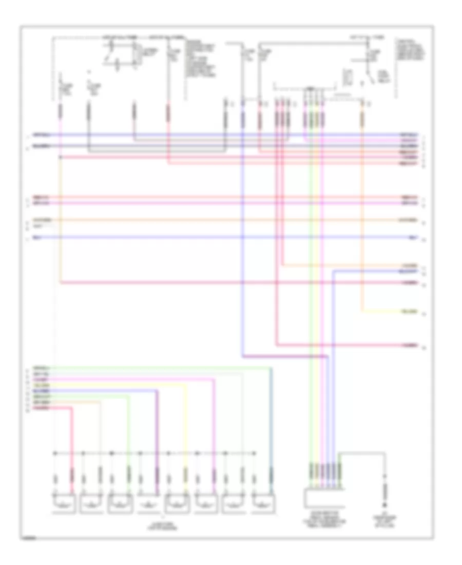
3.0L Turbo, Engine Performance Wiring Diagram (4 of 5) for Volvo S80 T-6 2009
 https://portal-diagnostov.com/license.html
Automotive Electricians Portal FZCO
Automotive Electricians Portal FZCO
https://portal-diagnostov.com/license.html
https://portal-diagnostov.com/license.html
Automotive Electricians Portal FZCO
Automotive Electricians Portal FZCOList of elements for 3.0L Turbo, Engine Performance Wiring Diagram (4 of 5) for Volvo S80 T-6 2009:
- 15-feed relay
- Accelerator pedal sensor (top of accelerator pedal assembly)
- Cem
- Central electronic module (cem) (behind right end of dash)
- Engine compartment distribution box (left side of engine compartment, forward of strut tower)
- Fuel pump relay
- Fuse b17 20a
- Fuse b20 7.5a
- Fuse b31 15a
- Fuse f22 20a
- Fuse f28 5a
- Fuse f4 7.5a
- G7 (near base of left "b" pillar)
- Hot at all times
- Injectors (top of engine)
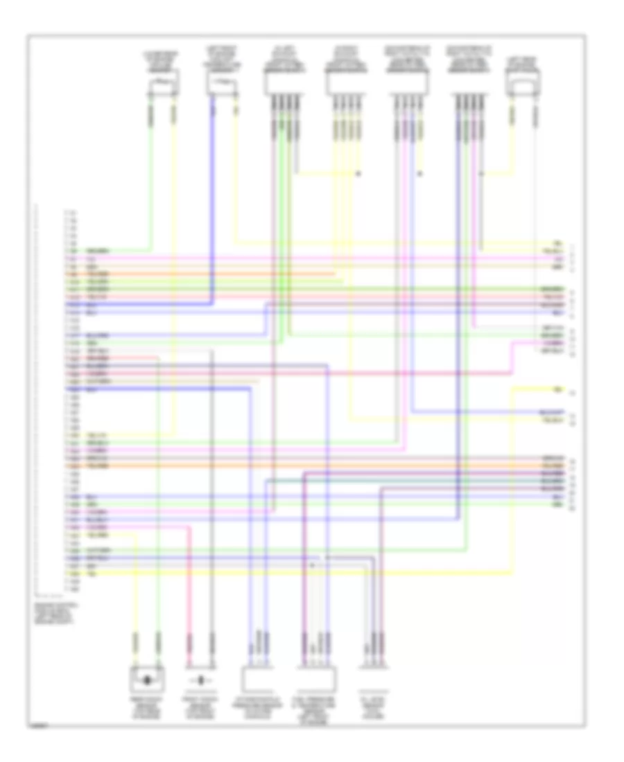
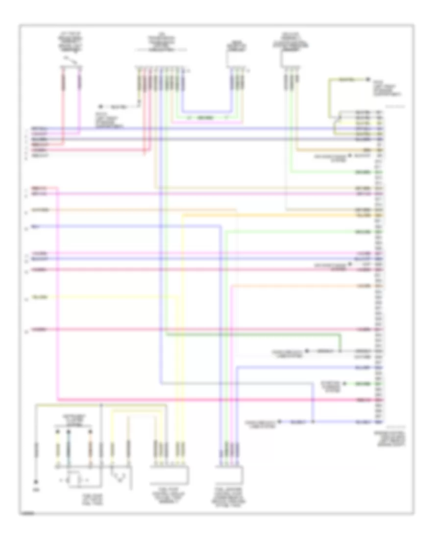
3.0L Turbo, Engine Performance Wiring Diagram (5 of 5) for Volvo S80 T-6 2009
 https://portal-diagnostov.com/license.html
Automotive Electricians Portal FZCO
Automotive Electricians Portal FZCO
https://portal-diagnostov.com/license.html
https://portal-diagnostov.com/license.html
Automotive Electricians Portal FZCO
Automotive Electricians Portal FZCOList of elements for 3.0L Turbo, Engine Performance Wiring Diagram (5 of 5) for Volvo S80 T-6 2009:
- (at top of brake pedal assembly) brake light contact
- (center console) gear selector module
- (on hvac assembly) climate control system pressure sensor
- (on transmission) transmission control module (tcm)
- Air conditioning system
- B10
- B11
- B12
- B13
- B14
- B15
- B16
- B17
- B18
- B19
- B20
- B21
- B22
- B23
- B24
- B25
- B26
- B27
- B28
- B29
- B30
- B31
- B32
- B33
- B34
- B35
- B36
- B37
- B38
- B39
- B40
- B41
- B42
- B43
- B44
- B45
- B46
- B47
- B48
- B49
- B50
- B51
- B52
- B53
- B54
- B55
- B56
- B57
- B58
- Computer data lines system
- Engine control module (ecm) (left rear of engine compt)
- Fuel leakage control pump (under rear of vehicle, forward of fuel tank)
- Fuel pump (at top of fuel tank)
- Fuel pump control module (on fuel tank assembly)
- G66 (base of left "c" pillar))
- Gxx10 (left front of engine compartment)
- Gxx5 (left front of engine compartment)
- Instrument cluster system
- Starting/charging system
3.2L
3.2L, Engine Performance Wiring Diagram (1 of 5) for Volvo S80 T-6 2009
 https://portal-diagnostov.com/license.html
Automotive Electricians Portal FZCO
Automotive Electricians Portal FZCO
https://portal-diagnostov.com/license.html
https://portal-diagnostov.com/license.html
Automotive Electricians Portal FZCO
Automotive Electricians Portal FZCOList of elements for 3.2L, Engine Performance Wiring Diagram (1 of 5) for Volvo S80 T-6 2009:
- (downstream of right catalytic converter) rear oxygen sensor (bank 1)
- (downstream of right catalytic converter) rear oxygen sensor (bank 2)
- (in left exhaust manifold) front oxygen sensor (bank 1)
- (in right exhaust manifold) front oxygen sensor (bank 2)
- (left front of engine) coolant temperature sensor
- (left rear of engine) evap valve
- (lower rear of engine) impulse sensor
- A10
- A11
- A12
- A13
- A14
- A15
- A16
- A17
- A18
- A19
- A20
- A21
- A22
- A23
- A24
- A25
- A26
- A27
- A28
- A29
- A30
- A31
- A32
- A33
- A34
- A35
- A36
- A37
- A38
- A39
- A40
- A41
- A42
- A43
- A44
- A45
- A46
- A47
- A48
- A49
- A50
- Engine control module (ecm) (left rear of engine compt)
- Front knock sensor (top front of engine)
- Fuel pressure & temperature sensor (left front of engine)
- Intake manifold pressure sensor (in intake manifold)
- Nca
- Oil level sensor (in oil cooler)
- Rear knock sensor (top rear of engine)
3.2L, Engine Performance Wiring Diagram (2 of 5) for Volvo S80 T-6 2009
 https://portal-diagnostov.com/license.html
Automotive Electricians Portal FZCO
Automotive Electricians Portal FZCO
https://portal-diagnostov.com/license.html
https://portal-diagnostov.com/license.html
Automotive Electricians Portal FZCO
Automotive Electricians Portal FZCOList of elements for 3.2L, Engine Performance Wiring Diagram (2 of 5) for Volvo S80 T-6 2009:
- (on intake manifold) intake manifold lower actuating motor
- (on intake manifold) intake manifold upper actuating motor
- (top front of engine) variable valve lifter (rear plane)
- (top left front of engine) variable valve timing intake solenoid
- (top rear of engine) variable valve lifter (front plane)
- (top right rear of engine) camshaft position sensor (exhaust side)
- (top right rear of engine) camshaft position sensor (intake side)
- Capacitor
- G88 (top front of engine, near spark plugs)
- G89 (left front of engine compt)
- Gxx10 (left front of engine compartment)
- Nca
- Spark plugs & ignition coils (top of engine)
3.2L, Engine Performance Wiring Diagram (3 of 5) for Volvo S80 T-6 2009
 https://portal-diagnostov.com/license.html
Automotive Electricians Portal FZCO
Automotive Electricians Portal FZCO
https://portal-diagnostov.com/license.html
https://portal-diagnostov.com/license.html
Automotive Electricians Portal FZCO
Automotive Electricians Portal FZCOList of elements for 3.2L, Engine Performance Wiring Diagram (3 of 5) for Volvo S80 T-6 2009:
- (at rear of engine, on air intake) mass airflow (maf) sensor
- A51
- A52
- A53
- A54
- A55
- A56
- A57
- A58
- A59
- A60
- A61
- A62
- A63
- A64
- A65
- A66
- A67
- A68
- A69
- A70
- A71
- A72
- A73
- A74
- A75
- A76
- A77
- A78
- A79
- A80
- A81
- A82
- A83
- A84
- A85
- A86
- A87
- A88
- A89
- A90
- A91
- A92
- A93
- A94
- A95
- A96
- A97
- Electronic throttle actuator (on throttle body)
- Engine compartment distribution box (left side of engine compartment, forward of strut tower)
- Engine control module (ecm) (left rear of engine compt)
- Engine management system main relay
- Fuse b30 10a
- Fuse b35 20a
- Fuse b36 10a
- Fuse b37 15a
- Fuse b38 10a
- Fuse b39 15a
- Fuse b41 5a
- Hot at all times
- Red
3.2L, Engine Performance Wiring Diagram (4 of 5) for Volvo S80 T-6 2009
 https://portal-diagnostov.com/license.html
Automotive Electricians Portal FZCO
Automotive Electricians Portal FZCO
https://portal-diagnostov.com/license.html
https://portal-diagnostov.com/license.html
Automotive Electricians Portal FZCO
Automotive Electricians Portal FZCOList of elements for 3.2L, Engine Performance Wiring Diagram (4 of 5) for Volvo S80 T-6 2009:
- 15-feed relay
- Accelerator pedal sensor (top of accelerator pedal assembly)
- Cem
- Central electronic module (cem) (behind right end of dash)
- Engine compartment distribution box (left side of engine compartment, forward of strut tower)
- Fuel pump relay
- Fuse b17 20a
- Fuse b20 7.5a
- Fuse b31 15a
- Fuse f22 20a
- Fuse f28 5a
- Fuse f4 7.5a
- G7 (near base of left "b" pillar)
- Hot at all times
- Injectors (top of engine)
3.2L, Engine Performance Wiring Diagram (5 of 5) for Volvo S80 T-6 2009
 https://portal-diagnostov.com/license.html
Automotive Electricians Portal FZCO
Automotive Electricians Portal FZCO
https://portal-diagnostov.com/license.html
https://portal-diagnostov.com/license.html
Automotive Electricians Portal FZCO
Automotive Electricians Portal FZCOList of elements for 3.2L, Engine Performance Wiring Diagram (5 of 5) for Volvo S80 T-6 2009:
- (at top of brake pedal assembly) brake light contact
- (on hvac assembly) climate control system pressure sensor
- (on transmission) transmission control module (tcm)
- Air conditioning system
- B10
- B11
- B12
- B13
- B14
- B15
- B16
- B17
- B18
- B19
- B20
- B21
- B22
- B23
- B24
- B25
- B26
- B27
- B28
- B29
- B30
- B31
- B32
- B33
- B34
- B35
- B36
- B37
- B38
- B39
- B40
- B41
- B42
- B43
- B44
- B45
- B46
- B47
- B48
- B49
- B50
- B51
- B52
- B53
- B54
- B55
- B56
- B57
- B58
- Computer data lines system
- Engine control module (ecm) (left rear of engine compt)
- Fuel leakage control pump (under rear of vehicle, forward of fuel tank)
- Fuel pump (at top of fuel tank)
- Fuel pump control module (on fuel tank assembly)
- G66
- Gear selector module
- Gxx10 (left front of engine compartment)
- Gxx5 (left front of engine compartment)
- Instrument cluster system
- Starting/charging system
4.4L
4.4L, Engine Performance Wiring Diagram (1 of 5) for Volvo S80 T-6 2009
 https://portal-diagnostov.com/license.html
Automotive Electricians Portal FZCO
Automotive Electricians Portal FZCO
https://portal-diagnostov.com/license.html
https://portal-diagnostov.com/license.html
Automotive Electricians Portal FZCO
Automotive Electricians Portal FZCOList of elements for 4.4L, Engine Performance Wiring Diagram (1 of 5) for Volvo S80 T-6 2009:
- (downstream of right catalytic converter) rear oxygen sensor (bank 1)
- (downstream of right catalytic converter) rear oxygen sensor (bank 2)
- (in left exhaust manifold) front oxygen sensor (bank 1)
- (in right exhaust manifold) front oxygen sensor (bank 2)
- (left front of engine) coolant temperature sensor
- (right side of engine) evap valve
- (top rear of engine) impulse sensor
- A10
- A11
- A12
- A13
- A14
- A15
- A16
- A17
- A18
- A19
- A20
- A21
- A22
- A23
- A24
- A25
- A26
- A27
- A28
- A29
- A30
- A31
- A32
- A33
- A34
- A35
- A36
- A37
- A38
- A39
- A40
- A41
- A42
- A43
- A44
- A45
- A46
- A47
- A48
- A49
- A50
- Engine control module (ecm) (left rear of engine compt)
- Front knock sensor (top front of engine)
- Fuel pressure & temperature sensor (left front of engine)
- Intake manifold pressure sensor (in intake manifold)
- Nca
- Oil level sensor (in oil cooler)
- Oil pressure sensor (lower left side of engine)
- Rear knock sensor (top rear of engine)
4.4L, Engine Performance Wiring Diagram (2 of 5) for Volvo S80 T-6 2009
 https://portal-diagnostov.com/license.html
Automotive Electricians Portal FZCO
Automotive Electricians Portal FZCO
https://portal-diagnostov.com/license.html
https://portal-diagnostov.com/license.html
Automotive Electricians Portal FZCO
Automotive Electricians Portal FZCOList of elements for 4.4L, Engine Performance Wiring Diagram (2 of 5) for Volvo S80 T-6 2009:
- (center rear of engine compartment) coolant pump
- (left front of engine compt) g89
- (left side of engine) g90
- (top front of engine) variable valve timing intake solenoid (bank 2)
- (top front of engine, near spark plugs)
- (top left front of engine) variable valve timing exhaust solenoid (bank 1)
- (top left front of engine) variable valve timing intake solenoid (bank 1)
- (top left rear of engine) camshaft position sensor (intake side) (bank 1)
- (top left rear) of engine) g100
- (top left side of engine) camshaft position sensor (exhaust side) (bank 1)
- (top right front of engine) variable valve timing exhaust solenoid (bank 2)
- (top right rear of engine) camshaft position sensor (exhaust side) (bank 2)
- (top right rear of engine) camshaft position sensor (intake side) (bank 2)
- Cyl 1
- Cyl 2
- Cyl 3
- Cyl 4
- Cyl 5
- Cyl 6
- Cyl 7
- Cyl 8
- G2 (at left front of engine compartment, on fender)
- G88
- Nca
- Red
- Spark plugs & ignition coils (top of engine)
4.4L, Engine Performance Wiring Diagram (3 of 5) for Volvo S80 T-6 2009
 https://portal-diagnostov.com/license.html
Automotive Electricians Portal FZCO
Automotive Electricians Portal FZCO
https://portal-diagnostov.com/license.html
https://portal-diagnostov.com/license.html
Automotive Electricians Portal FZCO
Automotive Electricians Portal FZCOList of elements for 4.4L, Engine Performance Wiring Diagram (3 of 5) for Volvo S80 T-6 2009:
- (at rear of engine, on air intake) mass airflow (maf) sensor
- A51
- A52
- A53
- A54
- A55
- A56
- A57
- A58
- A59
- A60
- A61
- A62
- A63
- A64
- A65
- A66
- A67
- A68
- A69
- A70
- A71
- A72
- A73
- A74
- A75
- A76
- A77
- A78
- A79
- A80
- A81
- A82
- A83
- A84
- A85
- A86
- A87
- A88
- A89
- A90
- A91
- A92
- A93
- A94
- A95
- A96
- A97
- Coolant pump relay
- Electronic throttle actuator (on throttle body)
- Engine compartment distribution box (left side of engine compt, forward of strut tower)
- Engine control module (ecm) (left rear of engine compt)
- Engine management system main relay
- Fuse b30 10a
- Fuse b33 5a
- Fuse b35 20a
- Fuse b36 10a
- Fuse b37 15a
- Fuse b38 10a
- Fuse b39 15a
- Fuse b40 10a
- Fuse b41 5a
- Hot at all times
- Red
- Variable intake valve (top front of engine)
4.4L, Engine Performance Wiring Diagram (4 of 5) for Volvo S80 T-6 2009
 https://portal-diagnostov.com/license.html
Automotive Electricians Portal FZCO
Automotive Electricians Portal FZCO
https://portal-diagnostov.com/license.html
https://portal-diagnostov.com/license.html
Automotive Electricians Portal FZCO
Automotive Electricians Portal FZCOList of elements for 4.4L, Engine Performance Wiring Diagram (4 of 5) for Volvo S80 T-6 2009:
- 15-feed relay
- Accelerator pedal sensor (top of accelerator pedal assembly)
- Cem
- Central electronic module (cem) (behind right end of dash)
- Engine compartment distribution box (left side of engine compartment, forward of strut tower)
- Fuel pump relay
- Fuse b17 20a
- Fuse b20 7.5a
- Fuse b31 15a
- Fuse f22 20a
- Fuse f28 5a
- Fuse f4 7.5a
- G7 (near base of left "b" pillar)
- Hot at all times
- Injectors (top of engine)
4.4L, Engine Performance Wiring Diagram (5 of 5) for Volvo S80 T-6 2009
 https://portal-diagnostov.com/license.html
Automotive Electricians Portal FZCO
Automotive Electricians Portal FZCO
https://portal-diagnostov.com/license.html
https://portal-diagnostov.com/license.html
Automotive Electricians Portal FZCO
Automotive Electricians Portal FZCOList of elements for 4.4L, Engine Performance Wiring Diagram (5 of 5) for Volvo S80 T-6 2009:
- (at top of brake pedal assembly) brake light contact
- (on hvac assembly) climate control system pressure sensor
- (on transmission) transmission control module (tcm)
- Air conditioning system
- B10
- B11
- B12
- B13
- B14
- B15
- B16
- B17
- B18
- B19
- B20
- B21
- B22
- B23
- B24
- B25
- B26
- B27
- B28
- B29
- B30
- B31
- B32
- B33
- B34
- B35
- B36
- B37
- B38
- B39
- B40
- B41
- B42
- B43
- B44
- B45
- B46
- B47
- B48
- B49
- B50
- B51
- B52
- B53
- B54
- B55
- B56
- B57
- B58
- Computer data lines system
- Engine control module (ecm) (left rear of engine compt)
- Fuel leakage control pump (under rear of vehicle, forward of fuel tank)
- Fuel pump (at top of fuel tank)
- Fuel pump control module (on fuel tank assembly)
- G66
- Gear selector module
- Gxx10 (left front of engine compartment)
- Gxx5 (left front of engine compartment)
- Instrument cluster system
- Starting/ charging system

 Čeština
 Dansk
Dansk Deutsch
 Ελληνικά
 English
 English
 Español
 Suomi
Suomi Français
 Français
 עברית
עברית Hrvatski
 Magyar
 Italiano
 한국어
한국어 Nederlands
 Polski
 Português
 Português
 Română
 Русский
 Slovenčina
 Slovenščina
 Svenska
 Türkçe
 中文 (中国)
