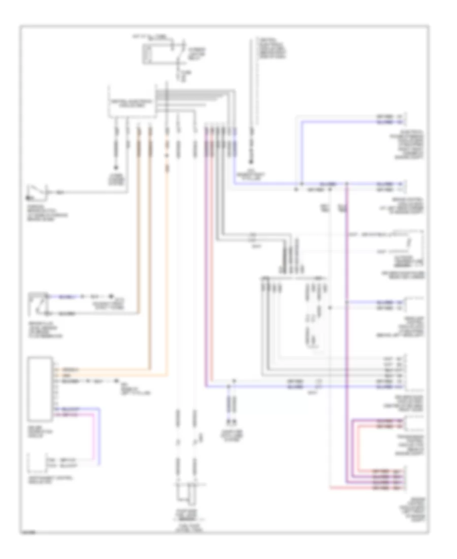
INSTRUMENT CLUSTER
Instrument Cluster Wiring Diagram for Volvo C30 T-5 2012
 https://portal-diagnostov.com/license.html
Automotive Electricians Portal FZCO
Automotive Electricians Portal FZCO
https://portal-diagnostov.com/license.html
https://portal-diagnostov.com/license.html
Automotive Electricians Portal FZCO
Automotive Electricians Portal FZCO
List of elements for Instrument Cluster Wiring Diagram for Volvo C30 T-5 2012:
- 64/333
- 64/41
- 64/51
- A10
- A12
- A17
- A28
- A38
- B14
- B41
- B44
- B54
- B57
- Brake control module (bcm) (at left rear corner of engine compt)
- Brake fluid level sensor (on brake fluid reservoir)
- C30
- C70
- Central electronic module (cem)
- Central electronic module (cem) (behind right side of dash)
- Computer data lines system
- Driver information module
- Driver's door module (ddm) (center of driver's front door)
- Driver's door power rear-view mirror
- Electrical power steering module (eps) (if equipped) (right front corner of engine compt)
- Engine control module (ecm) (left front of engine compt)
- F15
- F28
- F30
- F31
- Fuel pump (in fuel tank)
- Fuse 5a
- G10 (base of right "a" pillar)
- G110 (on right front strut tower)
- G14
- G15
- G27
- G28
- G83 (base of left "a" pillar)
- Headlamp control module (hcm) (if equipped) (behind left headlight)
- Hot at all times
- Infotainment control module (icm)
- Interior lighting relay
- Outdoor temperature sensor
- Parking brake switch (at base of parking brake lever)
- Pump side fuel level sensor
- Transmission control module (tcm) (rear of engine compt)
- Wiper/ washer system
 Čeština
 Dansk
Dansk Deutsch
 Ελληνικά
 English
 English
 Español
 Suomi
Suomi Français
 Français
 עברית
עברית Hrvatski
 Magyar
 Italiano
 한국어
한국어 Nederlands
 Polski
 Português
 Português
 Română
 Русский
 Slovenčina
 Slovenščina
 Svenska
 Türkçe
 中文 (中国)
 日本語
日本語
