POWER DISTRIBUTION
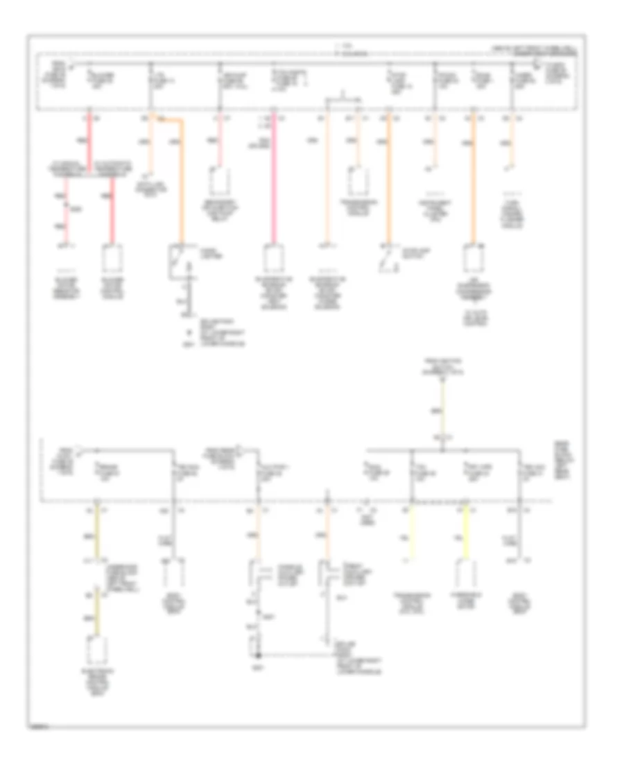
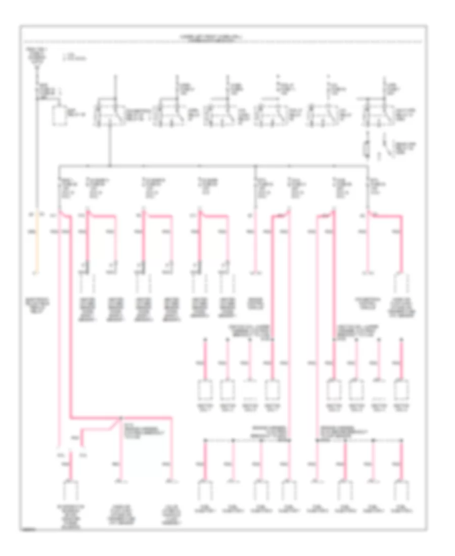
Power Distribution Wiring Diagram (1 of 6) for Chevrolet TrailBlazer 2007
 https://portal-diagnostov.com/license.html
Automotive Electricians Portal FZCO
Automotive Electricians Portal FZCO
https://portal-diagnostov.com/license.html
https://portal-diagnostov.com/license.html
Automotive Electricians Portal FZCO
Automotive Electricians Portal FZCO
List of elements for Power Distribution Wiring Diagram (1 of 6) for Chevrolet TrailBlazer 2007:
- (above left front wheelwell) underhood fuse block
- 1-2 shift solenoid (1-2 ss) valve
- 2-3 shift solenoid (2-3 ss) valve
- 3-2 shift solenoid (3-2 ss) valve
- 4.2l
- 4wd fuse 48 15a
- 5.3l & 6.0l
- A11
- A18
- Abs fuse 33 60a
- Acc
- Air suspension compressor assembly
- Atc fuse 8 30a
- Automatic transmission
- Automatic transmission shift lock actuator
- Auxiliary console mode actuator
- Auxiliary hvac control module
- B11
- Battery
- Body control module (bcm)
- C175
- Crank fuse 17 10a
- D9 c1
- Defrost actuator
- Elec brk fuse 19 30a
- Electronic brake control module (ebcm)
- Engine control module (ecm)
- Engine control module (ecm) (5.3l & 6.0l) powertrain control module (pcm) (4.2l)
- F11
- Flat- wire
- Front axle actuator
- Generator
- Hvac control module
- Hvac fuse 44 30a
- Hvac i fuse 39 10a
- I/p battery fuse 48 125a
- Ign a fuse 34 40a
- Ign b fuse 36 40a
- Ign o fuse 47 10a
- Ignition switch
- Left air temperature actuator
- Lock
- Mode actuator
- Nca
- Pnk
- Pnk (i/p harn, 18 cm from the a/t shift lever connector breakout) s320
- Powertrain control module (pcm)
- Rear fuse block (below left rear seat)
- Recirculation actuator
- Red
- Right air temperature actuator
- Run
- S133
- Start
- Starter
- Starter relay 47
- Steering wheel speed/ position sensor
- Tbc ig fuse 50 3a
- To blower fuse 35 (diagram 2 of 6)
- To brake fuse 51 (diagram 2 of 6)
- To rear fuse block (diagram 2 of 6)
- To rear fuse block lgm/dsm fuse 19 (diagram 4 of 6)
- To underhood fuse block (diagram 3 of 6)
- Torque converter clutch (tcc) solenoid valve
- Torque converter clutch pulse width modulation (tcc pwm) solenoid valve
- Trailer connector
- Trailer fuse 32 30a
- Transfer case encoder motor
- Transfer case shift control module
- Transfer case shift control switch
- Turn signal/ multifunction switch
- Underhood fuse block (above left front wheelwell)
- Vses fuse 58 fuse 61 60a
- W/ 2 speed push button control
- W/ all wheel drive
- W/ auto air level control
- W/ manual temperature controls
- W/ two speed push button control
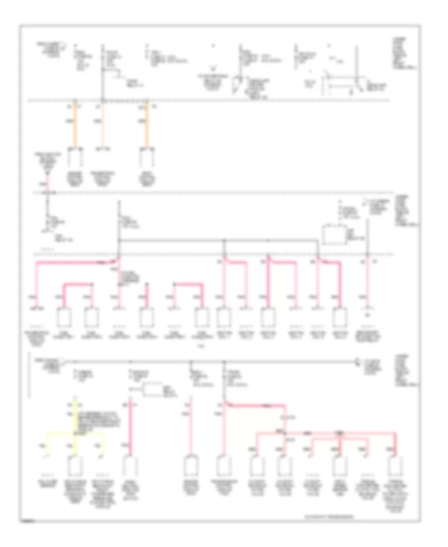
Power Distribution Wiring Diagram (2 of 6) for Chevrolet TrailBlazer 2007
 https://portal-diagnostov.com/license.html
Automotive Electricians Portal FZCO
Automotive Electricians Portal FZCO
https://portal-diagnostov.com/license.html
https://portal-diagnostov.com/license.html
Automotive Electricians Portal FZCO
Automotive Electricians Portal FZCOList of elements for Power Distribution Wiring Diagram (2 of 6) for Chevrolet TrailBlazer 2007:
- (4.2l)
- (above left front wheelwell) underhood fuse block
- (not used)
- 4.2l
- 5.3l & 6.0l
- A20
- Air pump fuse 56 60a
- Air suspension compressor assembly
- Aux pwr 1 fuse 46 20a
- B11
- B15
- Blower fuse 35 40a
- Blower motor control module
- Blower motor resistor assembly
- Body control module (bcm)
- Brake fuse 51 10a
- C11
- Cigar lighter
- Console auxiliary power outlet
- Data link connector (dlc)
- Ecas fuse 1 30a
- Electronic brake control module (bcm)
- Evaporative emission (evap) canister purge solenoid
- Evaporative emission (evap) canister vent solenoid
- Flat wire
- Flat- wire
- From b ign b fuse 36 (diagram 1 of 6)
- From c hvac i fuse 39 (diagram 1 of 6)
- From ignition switch (diagram 1 of 6)
- From rear l fuse block (diagram 4 of 6)
- Front auxiliary power outlet
- Frt wpr fuse 33 25a
- G201
- Hazrd fuse 52 25a
- Instrument panel cluster (ipc)
- Ipc/dic fuse 24 10a
- Ltr fuse 13 20a
- Rain fuse 29 10a
- Rear fuse block (below left rear seat)
- Red
- S250
- S307
- Secondary air injection (air) pump relay
- Splice pack sp201 (at lower right front of lower console)
- Stop lamp fuse 12 25a
- Stoplamp switch
- Tbc acc fuse 31 3a
- Tbc run fuse 52 3a
- Tcm cnstr fuse 26 fuse 15 10a
- Tcm fuse 35 10a
- To ecm fuse 29 (diagram 3 of 6)
- Transmission control module
- Transmission control module (5.3l, 6.0l)
- Turn signal/ hazard flasher module
- Underhood fuse block (above left front wheelwell)
- W/ auto air level control
- W/ automatic temperature controls
- W/ manual temperature controls
- Windshield wiper motor
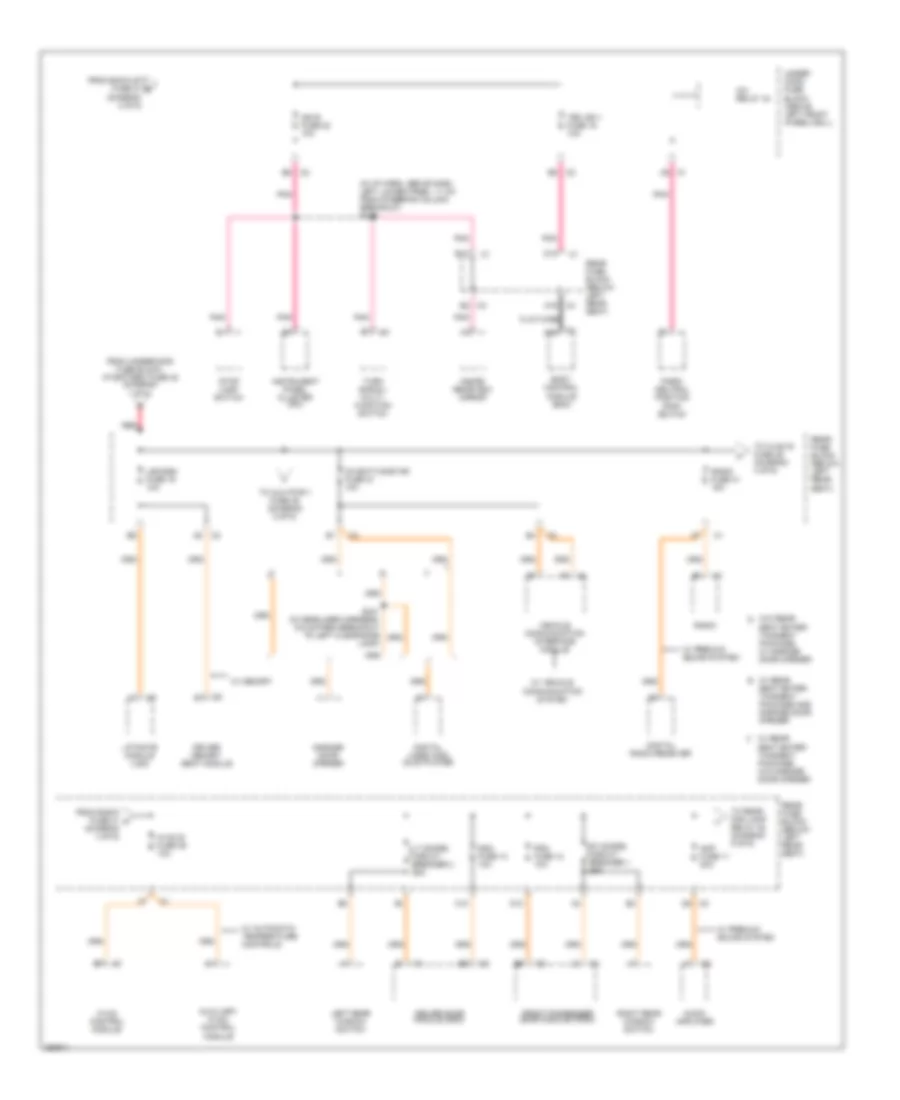
Power Distribution Wiring Diagram (3 of 6) for Chevrolet TrailBlazer 2007
 https://portal-diagnostov.com/license.html
Automotive Electricians Portal FZCO
Automotive Electricians Portal FZCO
https://portal-diagnostov.com/license.html
https://portal-diagnostov.com/license.html
Automotive Electricians Portal FZCO
Automotive Electricians Portal FZCOList of elements for Power Distribution Wiring Diagram (3 of 6) for Chevrolet TrailBlazer 2007:
- (4.2l)
- (4.2l) (5.3l & 6.0l)
- (i/p harness, 33.5 cm before breakout to inflatable restraint sensing & diagnostic module) s220
- (in fuel injector harness) s111
- (jf 4)
- 1-2 shift solenoid (1-2 ss) valve
- 2-3 shift solenoid (2-3 ss) valve
- 3-2 shift solenoid (3-2 ss) valve
- 4.2l
- 5.3l & 6.0l
- Air sol fuse 54 15a
- Air sol relay 55
- Airbag fuse 18 10a
- Automatic transmission
- Backup fuse 27 15a
- Body control module (bcm)
- E c175
- E12
- Eap relay
- Ecm 1 fuse 28 15a (5.3l & 6.0l)
- Ecm fuse 29 10a (5.3l & 6.0l)
- Engine control module (ecm)
- Engine control module (pcm)
- F/pmp relay 41
- Fan fuse 20 10a
- Fan relay 45
- From air sol fuse 54 f (diagram 3 of 6)
- From hazrd fuse 52 d (diagram 2 of 6)
- From ignition switch (diagram 1 of 6)
- Fuel injector 1
- Fuel injector 2
- Fuel injector 3
- Fuel injector 4
- Fuel injector 5
- Fuel injector 6
- Hdm fuse 53 fuse 57 15a
- Headlamp driver module (hdm) relay 46
- Hi headlamp relay 43
- Ign coils fuse 14 10a
- Ignition coil 1
- Ignition coil 2
- Ignition coil 3
- Ignition coil 4
- Ignition coil 5
- Ignition coil 6
- Inflatable restraint front passenger pressure system (pps) module
- Inflatable restraint sensing & diagnostic module (sdm)
- Input speed sensor (iss)
- Park/ neutral position (pnp) switch
- Pcm b fuse 10 20a (4.2l)
- Pcm i fuse 28 15a
- Pnk
- Powertrain control module (pcm)
- Red
- Rollover sensor
- S133
- S134
- Secondary air injection pump relay
- Tbc 1 fuse 31 fuse 58 10a
- To airbag fuse 18 (diagram 3 of 6)
- To ign e fuse 22 (diagram 4 of 6)
- To powertrain relay 60 (diagram 6 of 6)
- Torque converter clutch (tcc) solenoid valve
- Torque converter clutch pulse width modulation (tcc pwm) solenoid valve
- Trans fuse 53 15a (5.3l & 6.0l)
- Transmission control module (tcm)
- Under- hood fuse block (above left front wheelwell)
Power Distribution Wiring Diagram (4 of 6) for Chevrolet TrailBlazer 2007
 https://portal-diagnostov.com/license.html
Automotive Electricians Portal FZCO
Automotive Electricians Portal FZCO
https://portal-diagnostov.com/license.html
https://portal-diagnostov.com/license.html
Automotive Electricians Portal FZCO
Automotive Electricians Portal FZCOList of elements for Power Distribution Wiring Diagram (4 of 6) for Chevrolet TrailBlazer 2007:
- (in i/p harn, above dash left lower panel, 11 cm from steering column breakout) s239
- A/c relay 44
- A19
- Amp fuse 11 20a
- Audio amplifier
- Auxiliary hvac control module
- Body control module (bcm)
- C10
- D10
- D12
- Ddm fuse 10 10a
- Digital radio receiver
- Digital video disc (dvd) player
- Driver door module (ddm)
- Driver memory seat module
- E12
- Flat-wire
- From back-up fuse 27 g (diagram 3 of 6)
- From radio fuse 41 h (diagram 4 of 6)
- From underhood fuse block, i/p battery fuse 48 (diagram 1 of 6)
- Front passenger door module (fpdm)
- Garage door opener
- Hvac b fuse 36 10a
- Hvac control module
- Ign e fuse 22 10a
- Inside rearview mirror
- Instrument panel cluster (ipc)
- Left rear window switch
- Lgm/dsm fuse 19 10a
- Liftgate module (lgm)
- Lt doors circuit breaker 2 25a
- Oh batt/onstar fuse 27 10a
- Park/ neutral position (pnp) switch
- Pdm fuse 12 10a
- Pnk
- Radio
- Radio fuse 41 15a
- Rear fuse block (below left rear seat)
- Red
- Right rear window switch
- Rt doors circuit breaker 1 25a
- S341 (in headliner harness, 6.5 cm from breakout to left clearance lamp)
- Seat enter- tainment package and garage door opener
- Seat enter- tainment package, w/ garage door opener
- Seat enter- tainment package, w/o garage door opener
- Stop lamp switch
- Tbc ign 1 fuse 16 10a
- To aux pwr 1 fuse 46 (diagram 2 of 6)
- To hvac b fuse 36 (diagram 4 of 6)
- To rear fog lamp relay 45 (diagram 5 of 6)
- Turn signal/ multi- function switch
- Under- hood fuse block (above left front wheelwell)
- Vehicle communication interface module
- W/ automatic temperature controls
- W/ memory
- W/ premium sound system
- W/ rear e
- W/ rear f
- W/ vehicle communication system
- W/o rear d
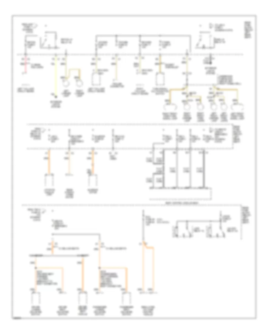
Power Distribution Wiring Diagram (5 of 6) for Chevrolet TrailBlazer 2007
 https://portal-diagnostov.com/license.html
Automotive Electricians Portal FZCO
Automotive Electricians Portal FZCO
https://portal-diagnostov.com/license.html
https://portal-diagnostov.com/license.html
Automotive Electricians Portal FZCO
Automotive Electricians Portal FZCOList of elements for Power Distribution Wiring Diagram (5 of 6) for Chevrolet TrailBlazer 2007:
- (4.2l) (5.3l & 6.0l)
- (diagram 4 of 6)
- (exc gmc)
- (gmc)
- (not used)
- 10a (diagram 5 of 6)
- A14 flat wire
- B13
- B17
- Body control module (bcm)
- Buick
- Driver lumbar adjuster switch
- Driver memory seat module
- Driver seat adjuster switch
- Except chevrolet
- Exterior lights system
- F park fuse 37 10a
- Flat wire
- From amp fuse 11 i
- From park lp j
- From tbc 5 fuse 32 k
- Left front marker lamp
- Left front park lamps
- Left front park/turn signal lamp
- Left license lamp
- Left taillamp circuit board
- Lgm 2 fuse 3 30a
- Liftgate module (lgm)
- Lock relay 18
- Locks fuse 21 10a
- Lr park fuse 14 10a
- Park lp relay 30
- Passenger lumbar adjuster switch
- Passenger seat adjuster switch
- Rear fuse block (below left rear seat)
- Rear window wiper motor
- Red
- Regulated voltage control module
- Relay 30 (diagram 5 of 6)
- Right front marker lamp
- Right front park lamps
- Right front park/turn signal lamp
- Right license lamp
- Right taillamp circuit board
- Rr fog fuse 5 10a
- Rr fog lp relay 45
- Rr hvac fuse 13 30a
- Rr park fuse 17 10a
- Rr wiper circuit breaker 9 15a
- Rvc fuse 49 fuse 62 10a
- S104
- S106
- S318 (driver's seat harness, 7 cm from breakout to body connector)
- S319 (passenger's seat harness, 7cm from 7 cm from breakout, body connector)
- Seats circuit breaker 8 30a
- Sunroof fuse 28 20a
- Sunroof motor
- Tbc 2 fuse 7 10a
- Tbc 3 fuse 4 10a
- Tbc 4 fuse 40 10a
- Tbc 5 fuse 32 10a
- To lgm 2 fuse 3 (diagram 5 of 6)
- To seats circut breaker 8 30a (diagram 5 of 6)
- Tr park fuse 42 10a
- Trailer connector
- Turn signal/ multifunction switch
- Underhood fuse block (above left front wheelwell)
- Unlock relay 24
- W/ deluxe seats
- W/ memory
- W/ rear fog lamps
- W/o memory
Power Distribution Wiring Diagram (6 of 6) for Chevrolet TrailBlazer 2007
 https://portal-diagnostov.com/license.html
Automotive Electricians Portal FZCO
Automotive Electricians Portal FZCO
https://portal-diagnostov.com/license.html
https://portal-diagnostov.com/license.html
Automotive Electricians Portal FZCO
Automotive Electricians Portal FZCOList of elements for Power Distribution Wiring Diagram (6 of 6) for Chevrolet TrailBlazer 2007:
- (engine harness, 10 cm from breakout to ecm) s100
- (engine harness, 22 cm before breakout to map sensor) s102
- (ignition coil jumper harness, 5 cm from breakout to c108) s108
- (ignition coil jumper harness, 5 cm from breakout to c109) s109
- (under left front wheelwell) underhood fuse block
- 02 snsr fuse 29 10a (4.2)
- 02 snsr a fuse 55 10a (5.3l & 6.0l)
- 02 snsr b fuse 54 10a (5.3l & 6.0l)
- 4.2l
- 5.3l
- 5.3l & 6.0l
- 6.0l
- A/c fuse 30 10a
- A/c relay
- A11
- C11
- Eap fuse 15 fuse 59 15a
- Eap relay 49
- Electronic adjustable pedals relay
- Eng 1 fuse 26 15a (5.3l & 6.0l)
- Engine control module
- Etc fuse 23 10a (4.2l)
- Etc fuse 23 15a (5.3l & 6.0l)
- Evaporative emission (evap) canister purge solenoid
- F10
- F11
- Fog lp fuse 11 15a
- Fog lp relay
- From tbc 1 fuse 31 (diagram 3 of 6)
- Fuel injector 1
- Fuel injector 2
- Fuel injector 3
- Fuel injector 4
- Fuel injector 5
- Fuel injector 6
- Fuel injector 7
- Fuel injector 8
- Hdlp wpr relay 37 (ce4)
- Heated oxygen sensor (ho2s) bank 1 sensor 1
- Heated oxygen sensor (ho2s) bank 1 sensor 2
- Heated oxygen sensor (ho2s) bank 2 sensor 1
- Heated oxygen sensor (ho2s) bank 2 sensor 2
- Heated oxygen sensor (ho2s) sensor 1
- Heated oxygen sensor (ho2s) sensor 2
- Horn fuse 21 15a
- Horn relay
- Ignition coil 1
- Ignition coil 2
- Ignition coil 3
- Ignition coil 4
- Ignition coil 5
- Ignition coil 6
- Ignition coil 7
- Ignition coil 8
- Inja fuse 31 20a (5.3l & 6.0l)
- Injb fuse 56 20a (5.3l & 6.0l)
- Mass air flow (maf)/ intake air temperature (iat) sensor
- Nca
- Pnk
- Powertrain control module
- Powertrain relay 57 relay 60
- Rear wpr relay 38 (cd6)
- S112 (engine harness, 5 cm from breakout to c109)
- Valve lifter oil manifold (vlom) assembly
- W/s wash relay
- Wash fuse 9 15a
- Wpr fuse 7 20a

 Čeština
 Dansk
Dansk Deutsch
 Ελληνικά
 English
 English
 Español
 Suomi
Suomi Français
 Français
 עברית
עברית Hrvatski
 Magyar
 Italiano
 한국어
한국어 Nederlands
 Polski
 Português
 Português
 Română
 Русский
 Slovenčina
 Slovenščina
 Svenska
 Türkçe
 中文 (中国)
