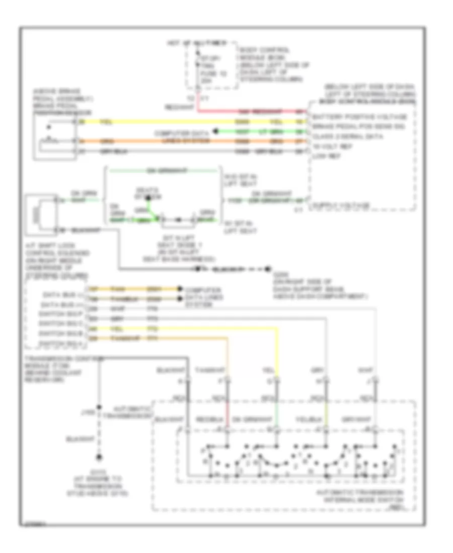
SHIFT INTERLOCK
Shift Interlock Wiring Diagram for Chevrolet Uplander LS 2008
 https://portal-diagnostov.com/license.html
Automotive Electricians Portal FZCO
Automotive Electricians Portal FZCO
https://portal-diagnostov.com/license.html
https://portal-diagnostov.com/license.html
Automotive Electricians Portal FZCO
Automotive Electricians Portal FZCO
List of elements for Shift Interlock Wiring Diagram for Chevrolet Uplander LS 2008:
- (above brake pedal assembly) brake pedal position sensor
- (below left side of dash, left of steering column) body control module (bcm)
- 10 volt ref
- A/t shift lock control solenoid (on right middle underside of steering column)
- Automatic transmission
- Automatic transmission internal mode switch (ims)
- Battery positive voltage
- Body control module (bcm) (below left side of dash, left of steering column)
- Brake pedal pos sens sig
- Class 2 serial data
- Computer data lines system
- Data bus (+)
- Data bus (-)
- G113 (at engine to transmission stud above g115)
- G200 (on right side of dash support beam, above dash compartment)
- Hot at all times
- J155
- J277
- Low ref
- Nca
- Seats system
- Sit n lift seat diode 1 (in sit-n-lift seat base harness)
- Stop/ trn fuse 12 20a
- Switch sig a
- Switch sig b
- Switch sig c
- Switch sig p
- Tan
- Transmission control module (tcm) (behind coolant reservoir)
- W/ sit-n- lift seat
- W/o sit-n- lift seat
 Čeština
 Dansk
Dansk Deutsch
 Ελληνικά
 English
 English
 Español
 Suomi
Suomi Français
 Français
 עברית
עברית Hrvatski
 Magyar
 Italiano
 한국어
한국어 Nederlands
 Polski
 Português
 Português
 Română
 Русский
 Slovenčina
 Slovenščina
 Svenska
 Türkçe
 中文 (中国)
 日本語
日本語
