SUPPLEMENTAL RESTRAINTS
Supplemental Restraints Wiring Diagram (1 of 3) for Chevrolet Malibu LT 2014
 https://portal-diagnostov.com/license.html
Automotive Electricians Portal FZCO
Automotive Electricians Portal FZCO
https://portal-diagnostov.com/license.html
https://portal-diagnostov.com/license.html
Automotive Electricians Portal FZCO
Automotive Electricians Portal FZCO
List of elements for Supplemental Restraints Wiring Diagram (1 of 3) for Chevrolet Malibu LT 2014:
- (center of steering wheel) steering wheel air bag
- (not used)
- Air bag ind
- Battery positive voltage
- Bdy rc ign fuse 10a
- Belt ind passenger seat
- Computer data lines system
- Driver information center display
- Driver knee air bag (lower left of dash)
- Drv knee mod hi ctrl
- Drv knee mod lo ctrl
- Fuse 5a
- G302 (right kick panel)
- G303 (below left front seat on floor)
- G403 (left rear wheel well in luggage compt)
- Ground
- Hot at all times
- Hot w/ ignition main relay energized
- Inflatable restraint sensing & diagnostic module (sdm) (forward of transmission shift lever on floor)
- Instrument cluster
- Instrument panel fuse block (left side of dash)
- J136
- J204
- J302
- J309
- Left front impact sensor (near left radiator support)
- Lo spd
- Lo spd gmlan serial data
- Logic
- Nca
- Off ind air bag
- On ind air bag
- Pass air bag off ind ctrl
- Pass air bag on ind ctrl
- Pass ip mod stage 1 hi ctrl
- Pass ip mod stage 1 lo ctrl
- Pass ip mod stage 2 hi ctrl
- Pass ip mod stage 2 lo ctrl
- Pass knee mod hi ctrl
- Pass knee mod lo ctrl
- Pass seat belt ind
- Passenger air bag disabled indicator
- Passenger instrument panel air bag
- Passenger knee air bag (lower right of dash)
- Passenger presence module (passenger seat between cover & cushion)
- Passenger presence sensor (between passenger seat cover and cushion)
- Pin shorting bars engaged when module connector is disconnected from harness: (shorting bars are connected between following pins in connector x1: 1-2, 3-4, 5-6, 7-8, 21-22 & 23-24)
- Pnk
- Red
- Right front impact sensor (near right radiator support)
- Run/crank ignition 1 voltage
- Seat belt ind
- Shorting bar
- Steering wheel air bag coil
- Steering wheel mod stage 1 hi ctrl
- Steering wheel mod stage 1 lo ctrl
- Steering wheel mod stage 2 hi ctrl
- Steering wheel mod stage 2 lo ctrl
- Tan
- Underhood fuse block (left side of battery)
- X150
- X205
- X210
- X320
- X400
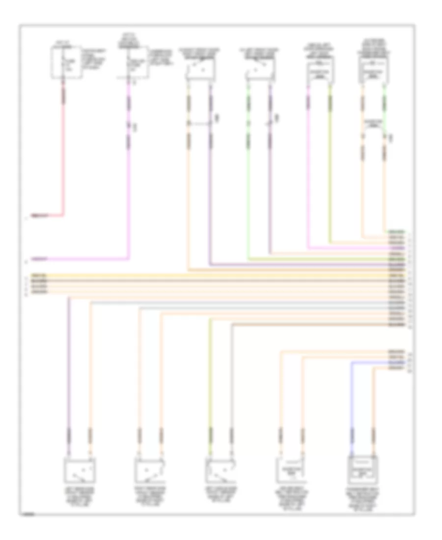
Supplemental Restraints Wiring Diagram (2 of 3) for Chevrolet Malibu LT 2014
 https://portal-diagnostov.com/license.html
Automotive Electricians Portal FZCO
Automotive Electricians Portal FZCO
https://portal-diagnostov.com/license.html
https://portal-diagnostov.com/license.html
Automotive Electricians Portal FZCO
Automotive Electricians Portal FZCOList of elements for Supplemental Restraints Wiring Diagram (2 of 3) for Chevrolet Malibu LT 2014:
- (above left door openings) left roof rail air bag
- (in left front door) left front side impact sensor
- (in right front door) right front side impact sensor
- (outboard side of seat back frame) passenger seat side air bag
- Driver seat belt retractor pretensioner (if equipped) (base of left "b" pillar)
- Fuse 10a
- Hot at all times
- Hot w/ ignition main relay energized
- Instrument panel fuse block (left side of dash)
- Left middle side impact sensor (base of left "b" pillar)
- Left rear side impact sensor (if equipped) (base of left "c" pillar)
- Passenger seat belt retractor pretensioner (if equipped) (base of right "b" pillar)
- Right rear side impact sensor (if equipped) (base of right "c" pillar)
- Sdm ign fuse 5a
- Shorting bar
- Underhood fuse block (left side of battery)
- X210
- X320
- X500
- X600
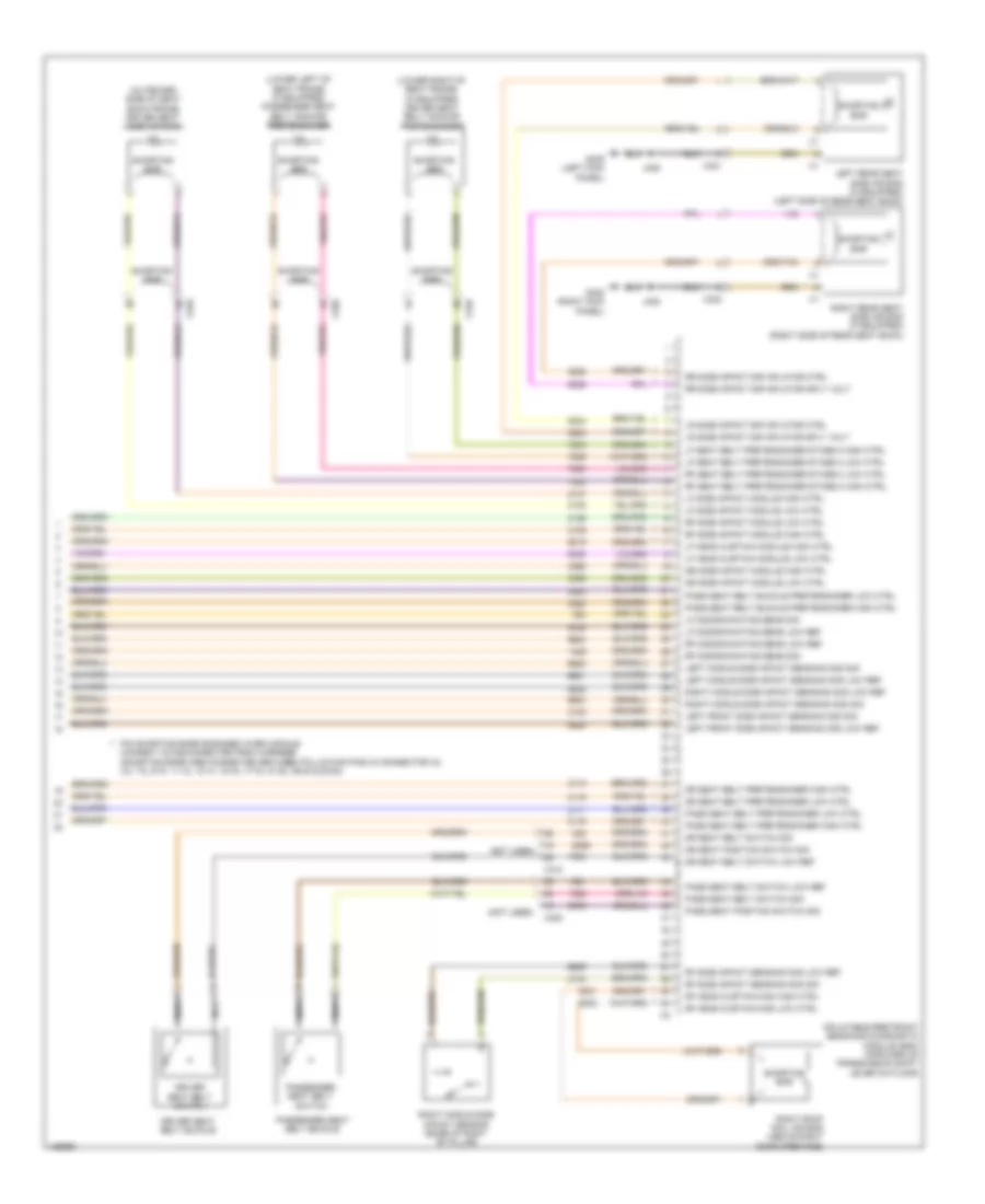
Supplemental Restraints Wiring Diagram (3 of 3) for Chevrolet Malibu LT 2014
 https://portal-diagnostov.com/license.html
Automotive Electricians Portal FZCO
Automotive Electricians Portal FZCO
https://portal-diagnostov.com/license.html
https://portal-diagnostov.com/license.html
Automotive Electricians Portal FZCO
Automotive Electricians Portal FZCOList of elements for Supplemental Restraints Wiring Diagram (3 of 3) for Chevrolet Malibu LT 2014:
- (lower left of seat frame) (if equipped) passenger seat belt anchor pretensioner
- (lower right of seat frame) (if equipped) driver seat belt anchor pretensioner
- (not used)
- (outboard side of seat back frame) driver seat side air bag
- Dr seat belt pretensioner high ctrl
- Dr seat belt pretensioner low ctrl
- Dr seat belt switch low ref
- Dr seat belt switch sig
- Dr seat position switch sig
- Dr side impact module high ctrl
- Dr side impact module low ctrl
- Driver seat belt buckle
- Driver seat belt switch
- G302 (right kick panel)
- G305 (left kick panel)
- Inflatable restraint sensing & diagnostic module (sdm) (forward of transmission shift lever on floor)
- J302
- J305
- Left front side impact sensing mod low ref
- Left front side impact sensing mod sig
- Left middle side impact sensing mod low ref
- Left middle side impact sensing mod sig
- Left rear seat side air bag (if equipped) (left side of rear seat back)
- Lf discriminating sens low ref
- Lf discriminating sens sig
- Lf head curtain module high ctrl
- Lf head curtain module low ctrl
- Lf seat belt pretensioner stage 2 high ctrl
- Lf seat belt pretensioner stage 2 low ctrl
- Lf side impact module high ctrl
- Lf side impact module low ctrl
- Lr side impact sir inflator ctrl
- Lr side impact sir inflator sply volt
- Nca
- Pass seat belt buckle pretensioner high ctrl
- Pass seat belt buckle pretensioner low ctrl
- Pass seat belt pretensioner high ctrl
- Pass seat belt pretensioner low ctrl
- Pass seat belt switch low ref
- Pass seat belt switch sig
- Pass seat position switch sig
- Passenger seat belt buckle
- Passenger seat belt switch
- Pin shorting bars engaged when module connect is disconnected from harness: (shorting bars are connected between following pins in connector x2: 3-4, 7-8, 9-10, 11-12, 13-14, 15-16, 17-18, 37-38, 39-40 & 53-54)
- Rf discriminating sens low ref
- Rf discriminating sens sig
- Rf head curtain mod high ctrl
- Rf head curtain mod low ctrl
- Rf seat belt pretensioner stage 2 high ctrl
- Rf seat belt pretensioner stage 2 low ctrl
- Rf side impact module high ctrl
- Rf side impact module low ctrl
- Rf side impact sensing mod low ref
- Rf side impact sensing mod sig
- Right middle side impact sensing mod low ref
- Right middle side impact sensing mod sig
- Right middle side impact sensor (base of right "b" pillar)
- Right rear seat side air bag (if equipped) (right side of rear seat back)
- Right roof rail air bag (above right door openings)
- Rr side impact sir inflator ctrl
- Rr side impact sir inflator sply volt
- Shorting bar
- X310
- X320
- X321
- X322

 Čeština
 Dansk
Dansk Deutsch
 Ελληνικά
 English
 English
 Español
 Suomi
Suomi Français
 Français
 עברית
עברית Hrvatski
 Magyar
 Italiano
 한국어
한국어 Nederlands
 Polski
 Português
 Português
 Română
 Русский
 Slovenčina
 Slovenščina
 Svenska
 Türkçe
 中文 (中国)
