AIR CONDITIONING
2.2L
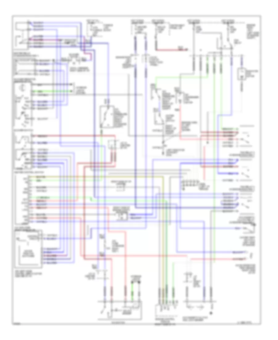
2.2L, A/C Wiring Diagram for Toyota Camry CE 1997
 https://portal-diagnostov.com/license.html
Automotive Electricians Portal FZCO
Automotive Electricians Portal FZCO
https://portal-diagnostov.com/license.html
https://portal-diagnostov.com/license.html
Automotive Electricians Portal FZCO
Automotive Electricians Portal FZCO
List of elements for 2.2L, A/C Wiring Diagram for Toyota Camry CE 1997:
- (cowl harness, right side of i/p)
- (engine harn, at left strut tower)
- (in engine room r/b 1)
- (left radiator support) g108
- 10a
- 1995 vftc c
- A/c condenser fan motor
- A/c dual pressure switch (right front of engine compt)
- A/c evaporator temp sensor (right side of i/p)
- A/c fuse (in engine room r/b 1)
- A/c magnetic clutch and lock sensor
- A/c magnetic clutch relay (in engine room r/b 1)
- A/c single pressure switch (right front of engine compt)
- A/c sw
- A/c switch
- A10
- A13
- A15
- A21
- Air vent mode control servo motor (center of i/p)
- B/l
- B10
- Blower motor
- Blower resistor (center of i/p)
- Blower switch
- C18
- Cds fuse 30a
- Circuit
- Control
- Def
- Ecu-ig fuse 15a
- Engine control module (right side of i/p)
- Engine room j/b 2 (left engine compt)
- Engine room j/b 2 (left side of engine compt)
- F/d
- Face
- Fan relay
- Fan relay 2 (in engine room r/b 1)
- Fan relay 3
- Foot
- Fusible link block
- G115 (on intake manifold)
- G206 (left i/p brace)
- Heater control switch
- Heater fuse 10a
- Heater relay (in engine room r/b 1)
- Hot at all
- Hot in run
- Htr fusible link 50a
- Instrument panel j/b
- Interior lights system
- J/c 12 (center of i/p)
- J/c 32 (top of right kick panel)
- J/c 8 (left side of i/p)
- Lock
- Lock in
- Mgc
- Motor position switches
- Off
- Or start
- Prs
- Radiator fan motor
- Rdi fuse 30a
- Red
- Solid state
- Thr
- Times
- Water temp switch (right front of engine compt)
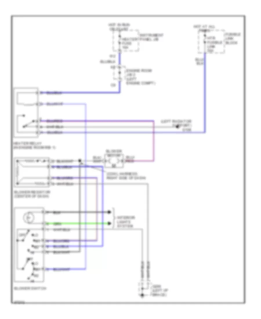
Heater Wiring Diagram for Toyota Camry CE 1997
 https://portal-diagnostov.com/license.html
Automotive Electricians Portal FZCO
Automotive Electricians Portal FZCO
https://portal-diagnostov.com/license.html
https://portal-diagnostov.com/license.html
Automotive Electricians Portal FZCO
Automotive Electricians Portal FZCOList of elements for Heater Wiring Diagram for Toyota Camry CE 1997:
- (cowl harness, right side of dash)
- (left radiator support) g108
- Blower motor
- Blower resistor (center of dash)
- Blower switch
- Engine room j/b 2 (left engine compt)
- Fusible link block
- G206 (left i/p brace)
- Heater fuse 10a
- Heater relay (in engine room r/b 1)
- Hot at all times
- Hot in run or start
- Htr fusible link 50a
- Instrument panel j/b
- Interior lights system
- Off
3.0L
3.0L, A/C Wiring Diagram for Toyota Camry CE 1997
 https://portal-diagnostov.com/license.html
Automotive Electricians Portal FZCO
Automotive Electricians Portal FZCO
https://portal-diagnostov.com/license.html
https://portal-diagnostov.com/license.html
Automotive Electricians Portal FZCO
Automotive Electricians Portal FZCOList of elements for 3.0L, A/C Wiring Diagram for Toyota Camry CE 1997:
- (cowl harness, right side of i/p)
- (engine harn, at left strut tower)
- (in engine room r/b 1)
- (left radiator support) g108
- (right side of engine compt) a/c diode
- (right side of i/p) j/c 27/28
- 10a
- 1995 vftc c
- A/c
- A/c amplifier (right side of i/p)
- A/c condenser fan motor
- A/c dual pressure switch (right front of engine compt)
- A/c evaporator temp sensor (right side of i/p)
- A/c fuse (in engine room r/b 1)
- A/c magnetic clutch and lock sensor
- A/c magnetic clutch relay (in engine room r/b 1)
- A/c single pressure switch (right front of engine compt)
- A/c switch
- A13
- A16
- Ac1
- Act
- Air vent mode control servo motor (center of i/p)
- B/l
- Blower motor
- Blower resistor (center of i/p)
- Blower switch
- Cds fuse 30a
- Circuit
- Control
- Def
- Ecu-ig fuse 15a
- Engine control module (right side of i/p)
- Engine room j/b 2 (left engine compt)
- Engine room j/b 2 (left side of engine compt)
- F/d
- Face
- Fan relay
- Fan relay 2 (in engine room r/b 1)
- Fan relay 3
- Foot
- Fusible link block
- G206 (left i/p brace)
- Gnd
- Heater control switch
- Heater fuse 10a
- Heater relay (in engine room r/b 1)
- Hot at all
- Hot in run
- Htr fusible link 50a
- Ign
- Instrument panel j/b
- Interior lights system
- J/c (right side of i/p)
- J/c 12 (center of i/p)
- J/c 32 (top of right kick panel)
- J13
- L-a/c
- Lock
- Mgc
- Motor position switches
- Off
- Or start
- Radiator fan motor
- Rdi fuse 30a
- Red
- S-a/c
- Solid state
- Tach
- Times
- Water temp switch (right front of engine compt)
- Water temp switch 2 (left side of engine)
Heater Wiring Diagram for Toyota Camry CE 1997
 https://portal-diagnostov.com/license.html
Automotive Electricians Portal FZCO
Automotive Electricians Portal FZCO
https://portal-diagnostov.com/license.html
https://portal-diagnostov.com/license.html
Automotive Electricians Portal FZCO
Automotive Electricians Portal FZCOList of elements for Heater Wiring Diagram for Toyota Camry CE 1997:
- (cowl harness, right side of dash)
- (left radiator support) g108
- Blower motor
- Blower resistor (center of dash)
- Blower switch
- Engine room j/b 2 (left engine compt)
- Fusible link block
- G206 (left i/p brace)
- Heater fuse 10a
- Heater relay (in engine room r/b 1)
- Hot at all times
- Hot in run or start
- Htr fusible link 50a
- Instrument panel j/b
- Interior lights system
- Off

 Čeština
 Dansk
Dansk Deutsch
 Ελληνικά
 English
 English
 Español
 Suomi
Suomi Français
 Français
 עברית
עברית Hrvatski
 Magyar
 Italiano
 한국어
한국어 Nederlands
 Polski
 Português
 Português
 Română
 Русский
 Slovenčina
 Slovenščina
 Svenska
 Türkçe
 中文 (中国)
