
 Čeština
 Dansk
Dansk Deutsch
 Ελληνικά
 English
 English
 Español
 Suomi
Suomi Français
 Français
 עברית
עברית Hrvatski
 Magyar
 Italiano
 한국어
한국어 Nederlands
 Polski
 Português
 Português
 Română
 Русский
 Slovenčina
 Slovenščina
 Svenska
 Türkçe
 中文 (中国)

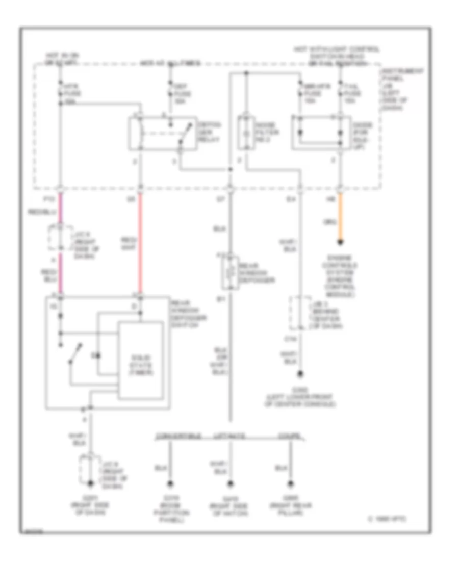
DEFOGGERS
Defogger Wiring Diagram for Toyota Celica GT 1999
List of elements for Defogger Wiring Diagram for Toyota Celica GT 1999:

AIR CONDITIONINGCOMPUTER DATA LINESCRUISE CONTROLANTI-LOCK BRAKESCOOLING FANEXTERIOR LIGHTSHEADLIGHTSDEFOGGERSHORNENGINE PERFORMANCEGROUND DISTRIBUTIONPOWER DISTRIBUTIONINTERIOR LIGHTSPOWER DOOR LOCKSPASSIVE RESTRAINTSPOWER MIRRORSPOWER ANTENNAINSTRUMENT CLUSTERPOWER WINDOWSPOWER TOP/SUNROOFSTARTING/CHARGINGSUPPLEMENTAL RESTRAINTSRADIOWARNING SYSTEMSSHIFT INTERLOCKSTRANSMISSIONWIPER/WASHER