POWER DISTRIBUTION
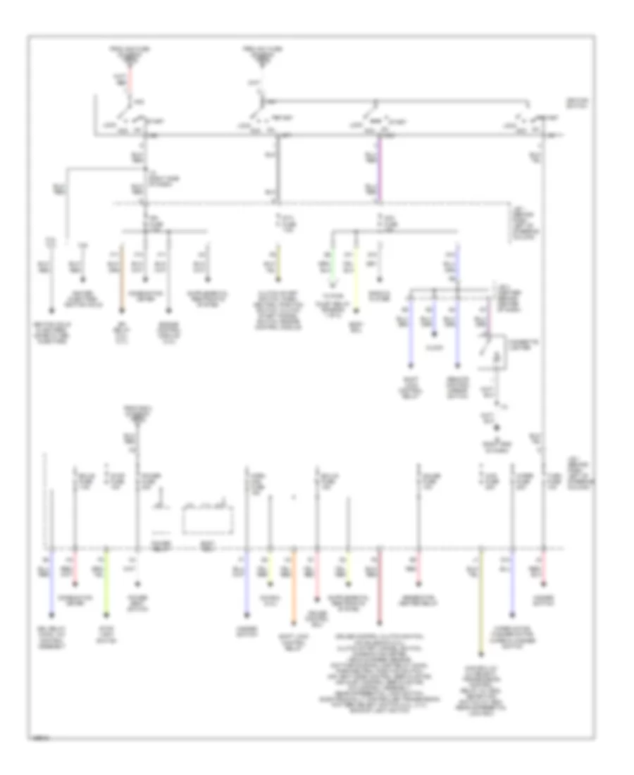
Power Distribution Wiring Diagram (1 of 2) for Toyota Tacoma 2003
 https://portal-diagnostov.com/license.html
Automotive Electricians Portal FZCO
Automotive Electricians Portal FZCO
https://portal-diagnostov.com/license.html
https://portal-diagnostov.com/license.html
Automotive Electricians Portal FZCO
Automotive Electricians Portal FZCO
List of elements for Power Distribution Wiring Diagram (1 of 2) for Toyota Tacoma 2003:
- (diagram 2 of 2)
- A/c dual pressure switch, a/c control assembly
- A/c fuse 10a
- Abs actuator w/ ecu
- Abs fuse 60a
- Alt fuse 120a
- Alt-s fuse 7.5a
- Am1 fuse 40a
- Am2 fuse 30a
- Battery
- Blower motor
- Body ecu, clock, radio & player, combination meter
- Combination meter, clock interior lights, exterior lights, engine control module, rheostat
- Compt)
- Data link connector
- Dimmer relay
- Dome fuse 15a
- Drl fuse 7.5a
- Drl relay 4
- Ea (left
- Efi fuse 20a
- Efi relay, engine control module
- End of dash)
- From acc
- Front fender)
- Fuse (diagram 2 of 2) d
- Generator
- Head (hi lh) fuse 10a
- Head (hi rh) fuse 10a
- Head (lh) fuse 10a
- Head (lo lh) fuse 10a
- Head (lo rh) fuse 10a
- Head (rh) fuse 10a
- Head relay
- Heater fuse 50a
- Heater relay
- I12
- Ie (right
- J/b fuse 50a
- J/c 11 (above glove box)
- J/c 9, j/c 10 (left side of engine compt)
- J10 d
- J9 a
- Left headlamp
- Obd fuse 7.5a
- Power outlets
- Pwr outlet fuse 15a
- Pwr outlet relay
- R/b 2 (left side of engine compt)
- Red
- Right headlamp
- Starter relay
- Switch (diagram 2 of 2)
- Tail fuse 10a
- Tail relay
- To ignition
- To j/b 1
- W/ drl
- W/o drl
Power Distribution Wiring Diagram (2 of 2) for Toyota Tacoma 2003
 https://portal-diagnostov.com/license.html
Automotive Electricians Portal FZCO
Automotive Electricians Portal FZCO
https://portal-diagnostov.com/license.html
https://portal-diagnostov.com/license.html
Automotive Electricians Portal FZCO
Automotive Electricians Portal FZCOList of elements for Power Distribution Wiring Diagram (2 of 2) for Toyota Tacoma 2003:
- 2.4l, 2.7l
- 3.4l
- 4wd ecu (w/ 2-4 select), transmission control relay (w/ add), detection switch (w/ add), rear differential lock ecu
- 4wd fuse 20a
- Acc
- Acc fuse 15a
- Am1
- Am2
- Body ecu
- Cigarette lighter
- Clock
- Clutch start switch, park/ neutral position switch, clutch start cancel switch, engine control module
- Combination meter
- Cruise control clutch switch, o/d solenoid (2.4l), clutch start cancel switch, combination meter, vehicle speed sensor, daytime running lamp relay (main), park/neutral position switch, air vent mode control servo motor, air inlet control servo motor, a/c control assembly, rear differential lock switch, electronically controlled transmission pattern select switch (2.4l, 2.7l), backup light switch
- Cruise control ecu
- Drl relay (main), a/c control assembly
- Ecu-b fuse 7.5a
- Ecu-ig fuse 15a
- Efi relay (2.4l, 2.7l)
- Engine control module (3.4l)
- F10
- F11
- From am1 fuse (diagram 1 of 2) b
- From am2 fuse (diagram 1 of 2) a
- From r/b 2 (diagram 1 of 2) c
- G10
- G11
- G12
- G13
- Gauge fuse 10a
- Generator, heater relay
- Hazard switch
- Horn haz fuse 15a
- I12
- I13 (right side of dash)
- Ie (right end of dash)
- Ig1
- Ig2
- Ign fuse 7.5a
- Igniter, injectors, ignition coils
- Ignition coils & igniters, noise filter, injectors
- Ignition switch
- J/b 1 (behind dash, left of steering column)
- J/b 3 (center) (behind center of dash)
- Lock
- O/d ecu (2.4l)
- Oulet relay (diagram 1 of 2)
- Power fuse 30a
- Power relay
- Power seat switch
- Radio & player
- Red
- Remote control mirror switch
- Shift lock control relay
- St1
- Sta fuse 7.5a
- Start
- Stop fuse 10a
- Stop light switch
- To pwr
- Turn fuse 10a
- Wiper fuse 20a
- Wiper motor, washer motor, wiper & washer switch

 Čeština
 Dansk
Dansk Deutsch
 Ελληνικά
 English
 English
 Español
 Suomi
Suomi Français
 Français
 עברית
עברית Hrvatski
 Magyar
 Italiano
 한국어
한국어 Nederlands
 Polski
 Português
 Português
 Română
 Русский
 Slovenčina
 Slovenščina
 Svenska
 Türkçe
 中文 (中国)
