
 Čeština
 Dansk
Dansk Deutsch
 Ελληνικά
 English
 English
 Español
 Suomi
Suomi Français
 Français
 עברית
עברית Hrvatski
 Magyar
 Italiano
 한국어
한국어 Nederlands
 Polski
 Português
 Português
 Română
 Русский
 Slovenčina
 Slovenščina
 Svenska
 Türkçe
 中文 (中国)

G - TESTS W/CODES - 2.6L EFI 1991 ENGINE PERFORMANCE Isuzu Self-Diagnostics - Fuel Injection - 2.6L
Isuzu Rodeo LS 1991 - INTRODUCTION
If no faults were found while performing F - EFI BASIC TESTING, proceed with self-diagnostics. If no fault codes or only pass codes are present after entering self-diagnostics, proceed to H - EFI TESTS W/O CODES article in the ENGINE PERFORMANCE Section for diagnosis by symptom (i.e. ROUGH IDLE, NO START, etc.).
Isuzu Rodeo LS 1991 - SELF-DIAGNOSTIC SYSTEM HARD FAILURES
Hard failures cause CHECK ENGINE light to illuminate and remain on until problem is repaired. If light comes on and remains on (light may flash) during vehicle operation, cause of malfunction must be determined using diagnostic (code) charts. If a sensor fails, Electronic Control Module (ECM) will use a substitute value in its calculations to continue engine operation. In this condition, commonly known as limp-in mode, the vehicle runs but driveability will not be optimum.
Isuzu Rodeo LS 1991 - INTERMITTENT FAILURES
Intermittent failures may cause CHECK ENGINE light to flicker or illuminate and go out after the intermittent fault goes away. However, the corresponding trouble code will be retained in Electronic Control Module (ECM) memory. If related fault does not reoccur within a certain time frame, related trouble code will be erased from ECM memory. Intermittent failures may be caused by a sensor, connector or wiring related problems. See INTERMITTENTS in H - EFI TESTS W/O CODES article in the ENGINE PERFORMANCE Section.
Isuzu Rodeo LS 1991 - RETRIEVING CODES
NOTE: Codes can also be retrieved using a Scan tester. Diagnostic connector may also be referred to as ALDL test lead.
- Code retrieval starts with the DIAGNOSTIC CIRCUIT CHECK. The CHECK ENGINE light will come on when ignition is on and engine is not running. When engine is started, CHECK ENGINE light should go off. If light remains on while engine is running, a trouble code is present.
- If light did not come on with key on and engine off, inspect CHECK ENGINE light circuit before continuing. If CHECK ENGINE light failed to operate, See DIAGNOSTIC CIRCUIT CHECK. Circuit checks are located within test charts.
- To retrieve codes, install jumper wire between ALDL diagnostic leads. See Fig. 1 . Turn ignition on. Count number of flashes from CHECK ENGINE light. A Code 12 is identified by a flash, pause and flash, flash. A long pause will occur. Code 12 will repeat 3 times. See Fig. 2 . Each additional code will flash 3 times starting with lowest code to the highest number code. Once all codes are displayed, codes will repeat.
- If system is operating properly (with no codes), a Code 12 should exist with ignition on and engine off. This indicates the diagnostic system is capable of storing codes. After codes are retrieved, remove jumper wire from diagnostic leads to exit diagnostic mode.


Fig. 1: Isuzu Rodeo LS 1991 - Component Locations - Locating Diagnostic Leads
Fig. 2: Isuzu Rodeo LS 1991 - Component Locations - Code Display (Typical)

Isuzu Rodeo LS 1991 - CLEARING CODES
- After repairs are performed, clear ECM memory of all stored codes. To clear memory, turn ignition off and remove appropriate fuse from fuse block. See CLEARING CODES table.
- Trouble codes can also be cleared by disconnecting negative battery cable. However, other memory functions (clock, radio, etc.) will then require resetting.
Isuzu Rodeo LS 1991 CLEARING CODES
Application Fuse Number Amigo, Pickup & Rodeo (1) 3 Trooper (2) 6
(1) Fuse is located in instrument panel fuse block. Code can also be cleared by removing 60-amp MAIN fuse, located in engine compartment fuse block.
(2) Fuse is located in fuse block, on left front corner of engine compartment.
Isuzu Rodeo LS 1991 ECM LOCATIONS
Model Location Amigo, Pickup & Rodeo Near Left Kick Panel Trooper Below Center Console Between Seats
Isuzu Rodeo LS 1991 - TROUBLE CODE IDENTIFICATION
Isuzu Rodeo LS 1991 TROUBLE CODE IDENTIFICATION
Code System Affected Probable Cause 12 System Normal System Normal 13 O2 Sensor Circuit Sensor/Circuit, ECM 14 Coolant Temp. Sensor (Shorted) Temp. Sensor/Ckt., ECM 15 Coolant Temp. Sensor (Open) Temp. Sensor/Circuit, ECM 21 Throttle Valve Switch (Idle & Full Throttle) Switch/Circuit, ECM 22 Starter Signal Circuit, ECM 23 Power Transistor (Shorted) Transistor/Circuit, ECM 25 Press. Regulator VSV VSV/Circuit, ECM 26 Canister Purge VSV VSV/Circuit, ECM 27 Canister Purge VSV VSV/Circuit, ECM 32 EGR System EGR Valve, Backpressure Transducer, Vacuum Switching Valve 33 Fuel Injector Circuit (Open or Grounded) Wiring, Dropping Resistor, ECM 34 EGR Temp. Sensor Sensor/Circuit, ECM 35 Power Transistor (Open) Transistor/Circuit, ECM 41 Crank Angle Sensor Sensor/Circuit, ECM 43 Throttle Valve Switch (Idle Position) Switch/Circuit, ECM 44 O2 Sensor (Lean/Rich) Injectors, Fuel Press., Airflow Sensor, O2 Sensor Circuit, Cool. Temp. Sensor, ECM 45 O2 Sensor (Lean/Rich) Injectors, Fuel Press., Airflow Sensor, O2 Sensor Circuit, Cool. Temp. Sensor, ECM 51 Faulty ECM ROM Defective ECM 52 Faulty ECM RAM Defective ECM 53 Press. Regulator VSV VSV/Circuit, ECM 54 Power Transistor (Grounded) Transistor/Circuit, ECM 61 Airflow Sensor Sensor/Circuit, ECM 62 Airflow Sensor Sensor/Circuit, ECM 63 Vehicle Speed Sensor Sensor/Circuit, ECM 64 Fuel Injector Circuit (ECM Transistor) Wiring Harness, ECM 65 Throttle Valve Switch (Full Throttle) Switch/Circuit, ECM
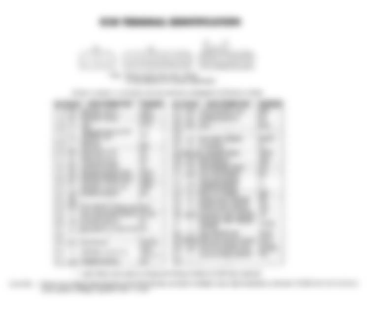
Isuzu Rodeo LS 1991 - ECM TERMINAL IDENTIFICATION
CAUTION: Perform all voltage measurements with ECM harness connector installed. Use a high-impedance voltmeter (10,000 ohm/volt minimum). Verify battery voltage is greater than 11 volts.
Fig. 3: Isuzu Rodeo LS 1991 - Component Locations - ECM Terminal Identification
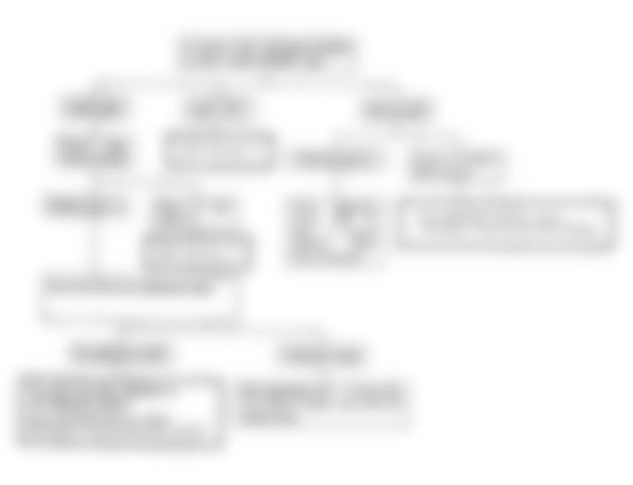
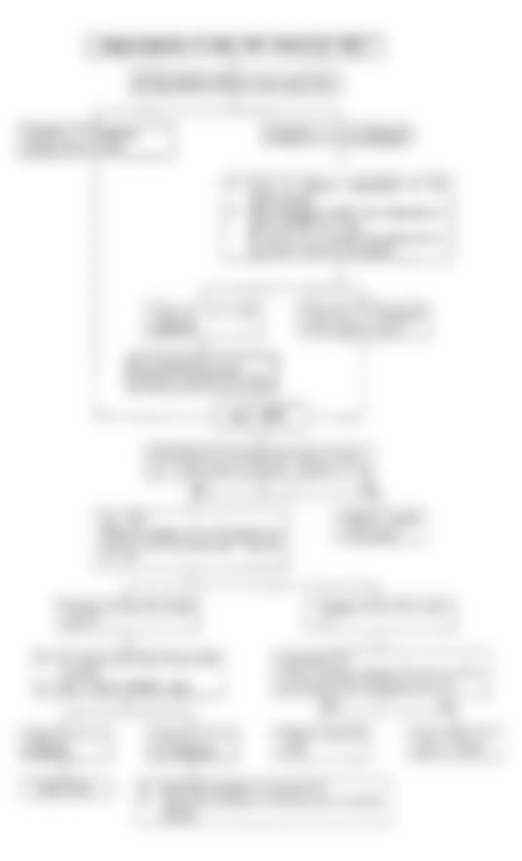
DIAGNOSTIC CIRCUIT CHECK
Fig. 4: Isuzu Rodeo LS 1991 - Component Locations - Diagnostic Circuit Check Flow Chart,
Isuzu Rodeo LS 1991 - TEST NO. 1 - ECM POWER SUPPLY
Checking ECM Unit Power Supply Circuit
Isuzu Rodeo LS 1991 - Confirmation
- Disconnect ECM unit harnesses at connectors.
- Turn key switch to ON position.
- Check that power voltage is present at connector terminals 33, 12 or 21.
- Check that continuity exists between the connector and terminals 11, 20 and ground.
Isuzu Rodeo LS 1991 - Inspection And Correction
- When power voltage is not present at terminals 33 and 12 or 21. Check the main relay, starter switch, fuses, fusible link wires and related circuits and correct or replace the parts as necessary.
- If the circuit tester does not indicate continuity across the terminals 11, 20 and ground, correct or replace grounding cable.
- Connect the ECM unit harnesses at connector properly.
Fig. 5: Isuzu Rodeo LS 1991 - Component Locations - Test No. 1 Schematic, ECM Power Supply

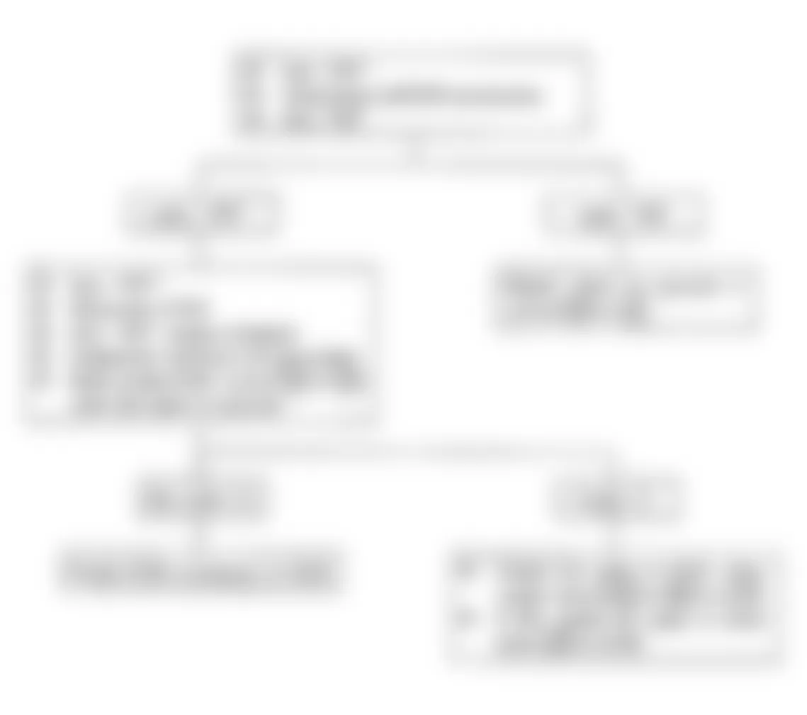
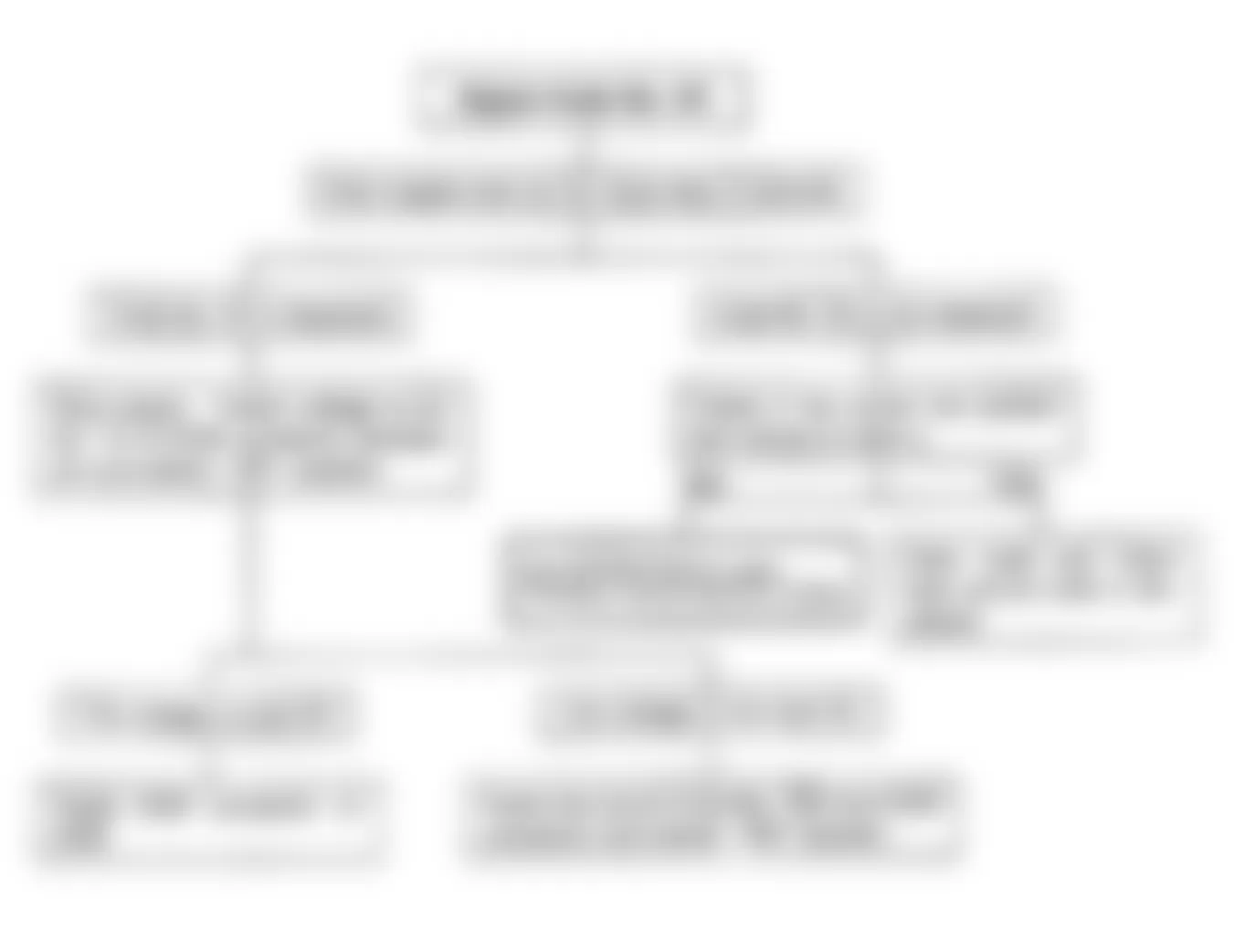
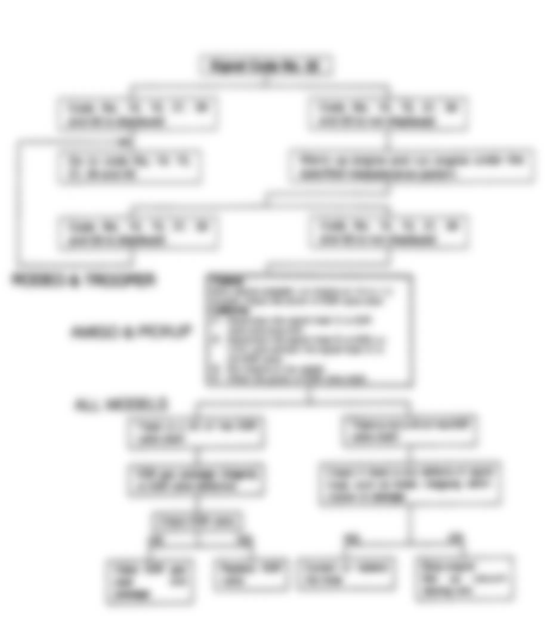
Isuzu Rodeo LS 1991 - TEST NO. 2 - CHECK ENGINE LIGHT INOPERATIVE
NOTE: Before replacing ECM, use an ohmmeter and check resistance of each ECM controlled relay and solenoid coil. See ECM wiring diagram for coil terminal identification for solenoid(s) and relay(s) to be checked. Replace any relay or solenoid if the coil resistance measures less than 20 ohms.
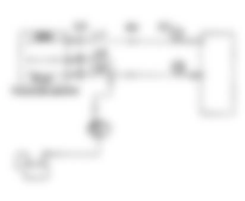
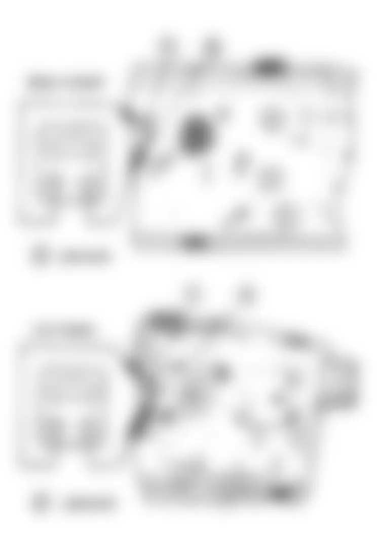
Fig. 6: Isuzu Rodeo LS 1991 - Component Locations - Test No. 2 Schematic,

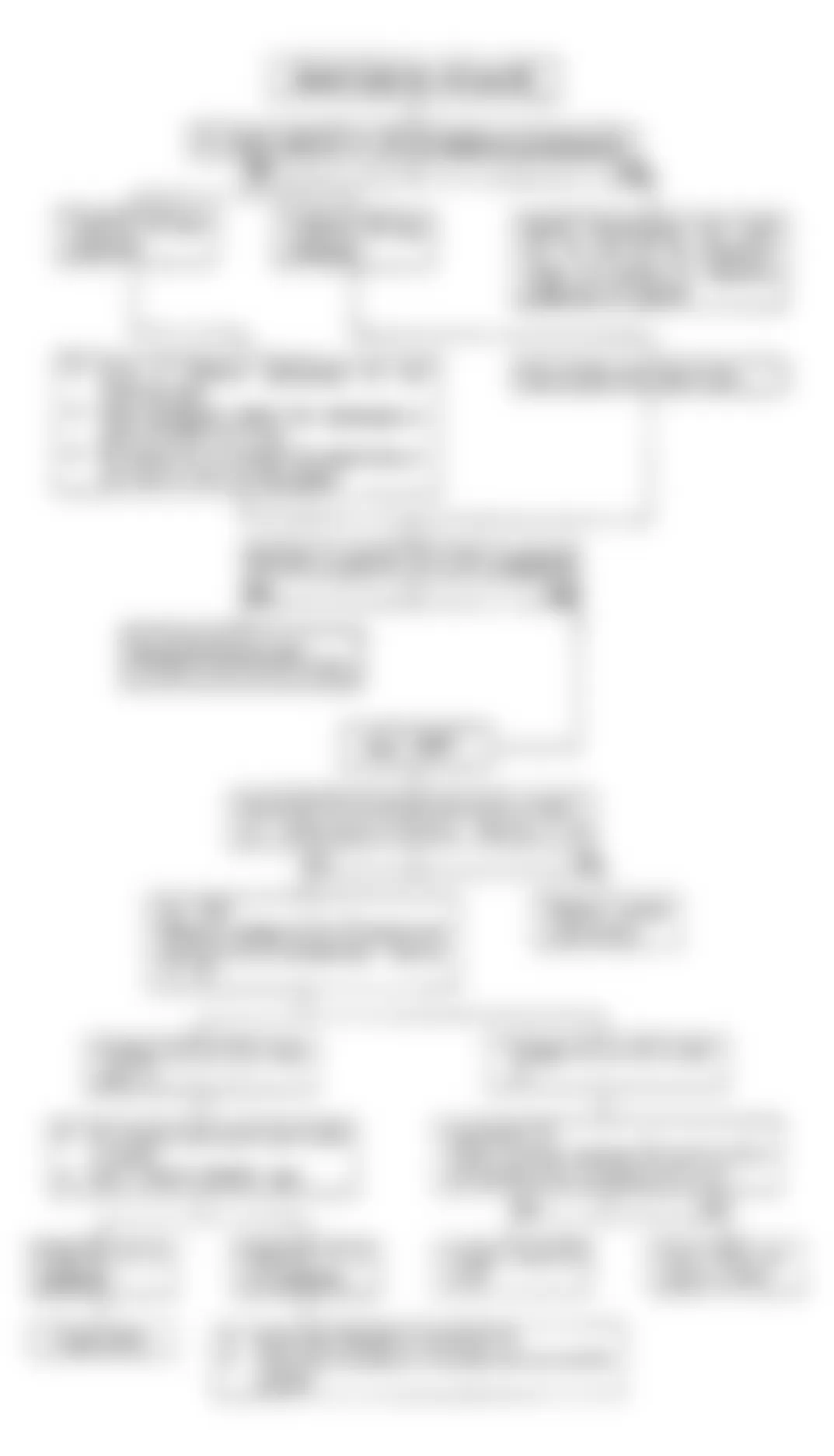
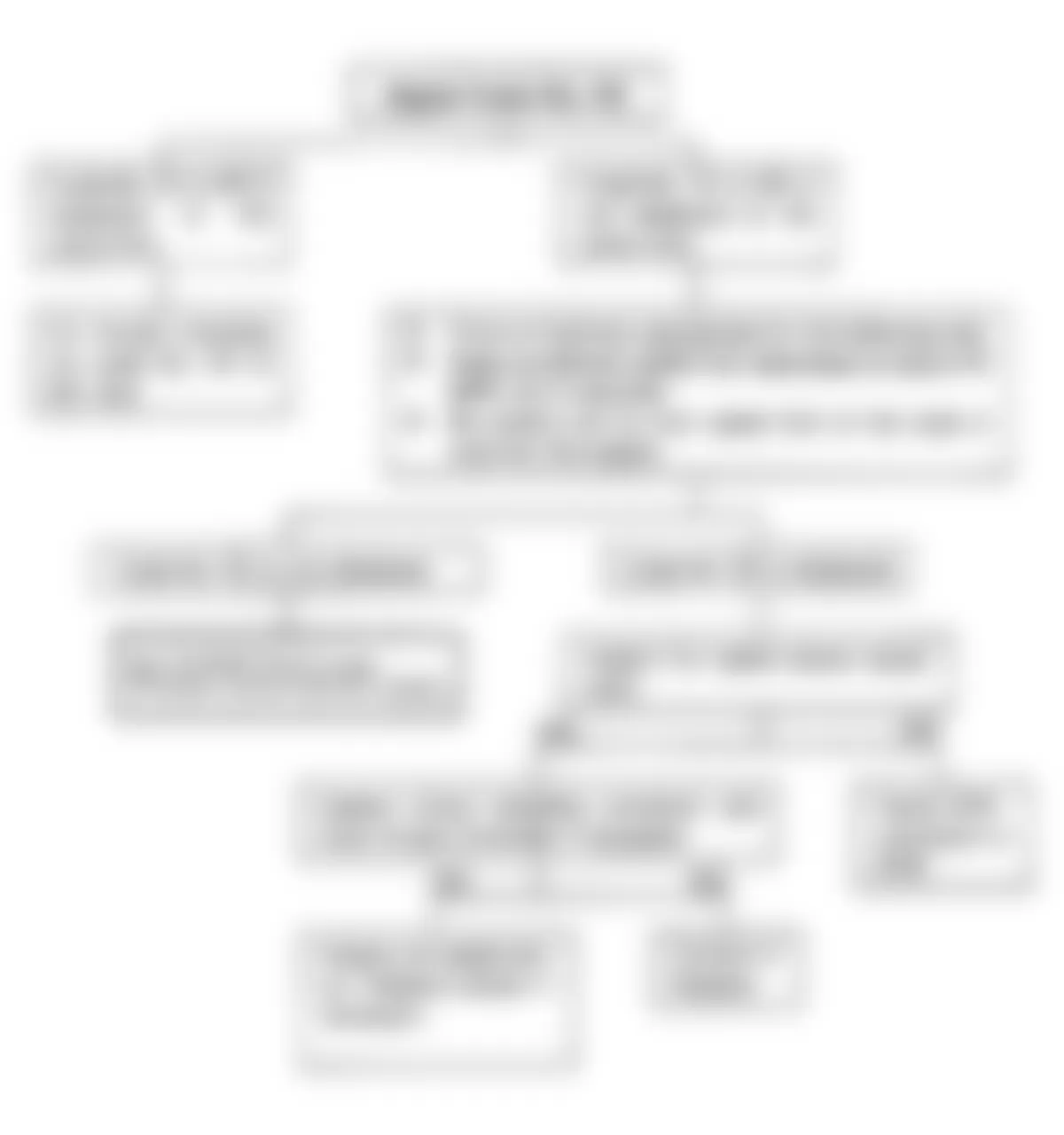
Fig. 7: Isuzu Rodeo LS 1991 - Component Locations - Test No. 2 Flow Chart,
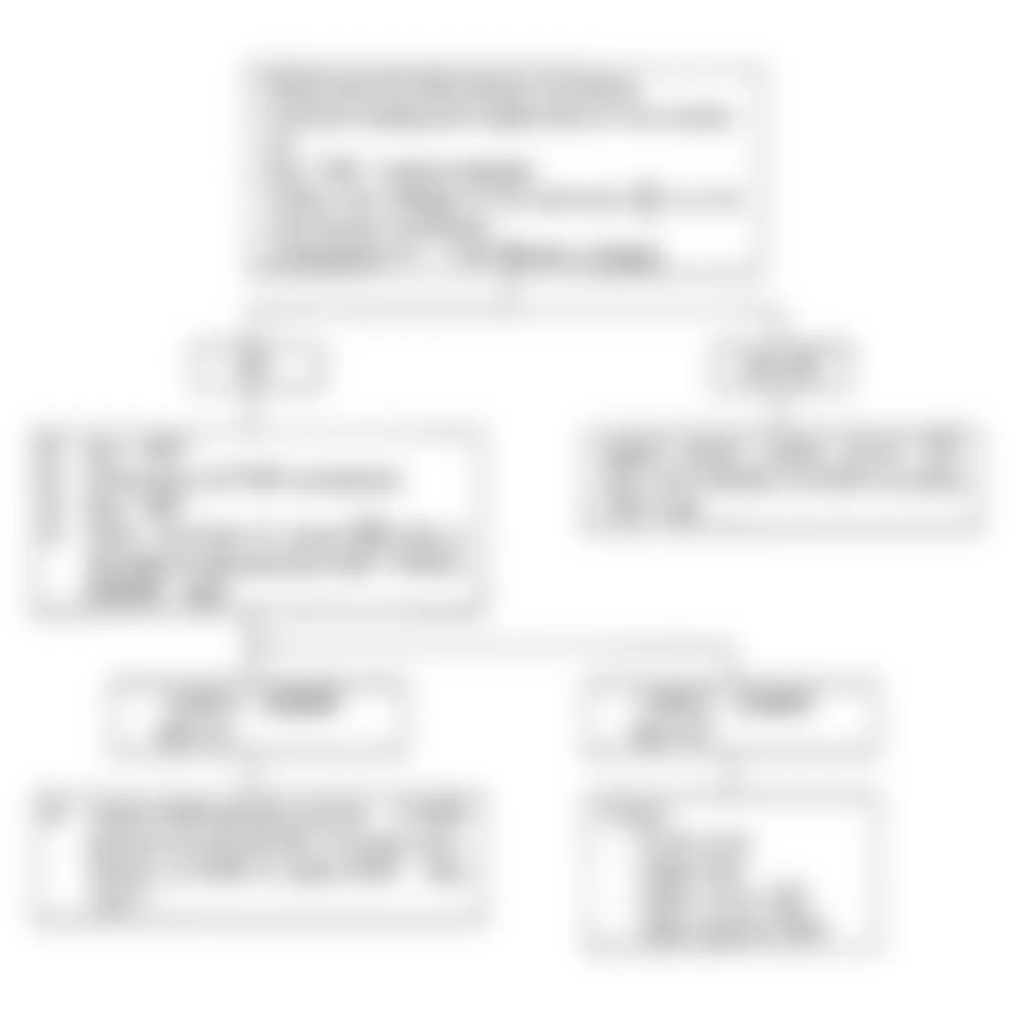
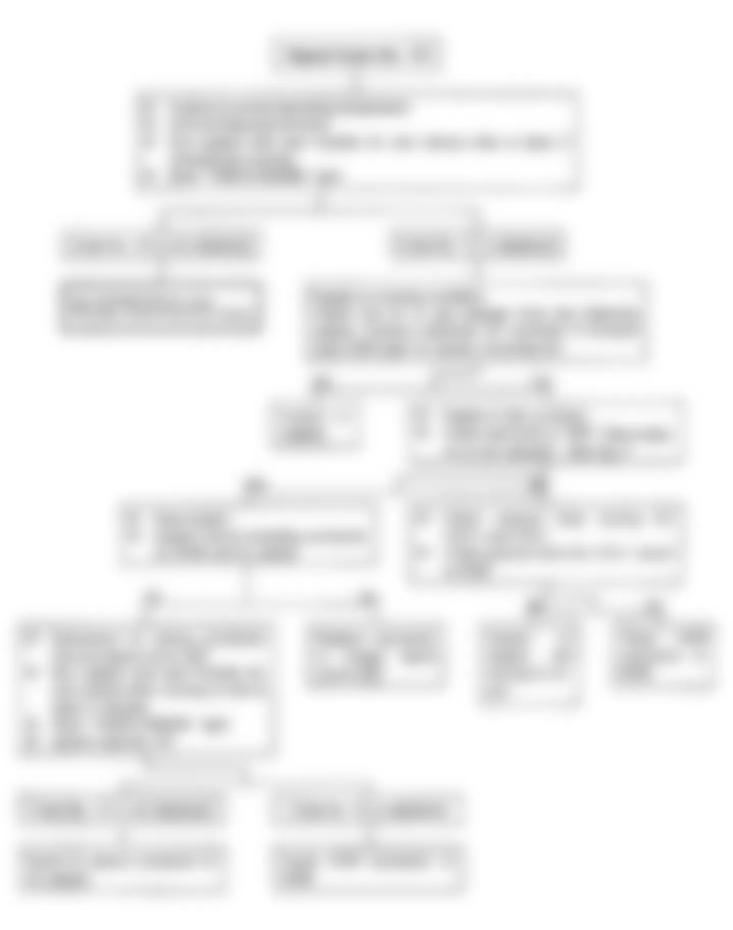
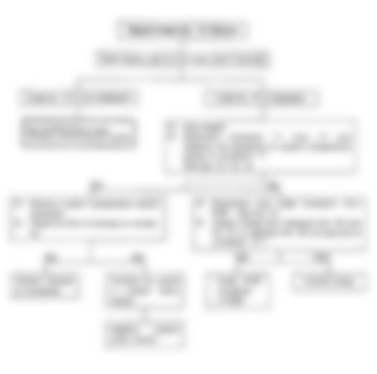
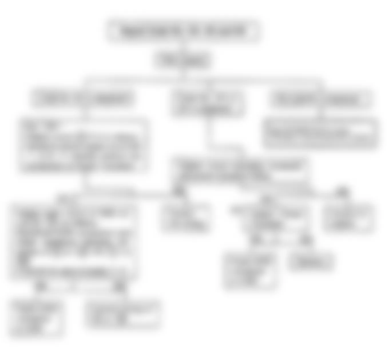
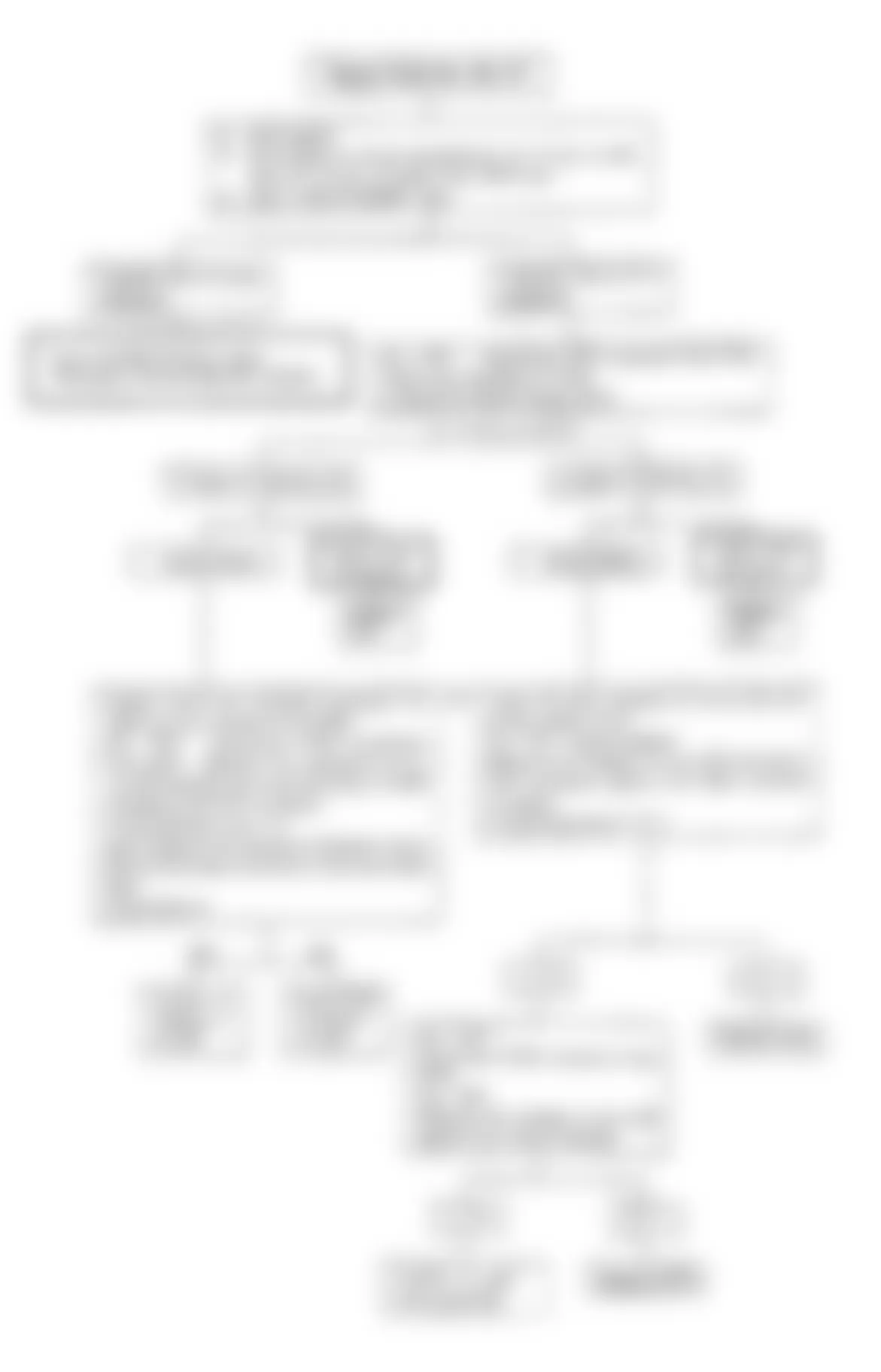
Isuzu Rodeo LS 1991 - TEST NO. 3 - WILL NOT FLASH CODE NO. 12
Fig. 8: Isuzu Rodeo LS 1991 - Component Locations - Test No. 3 Schematic, Won't Flash Code No. 12
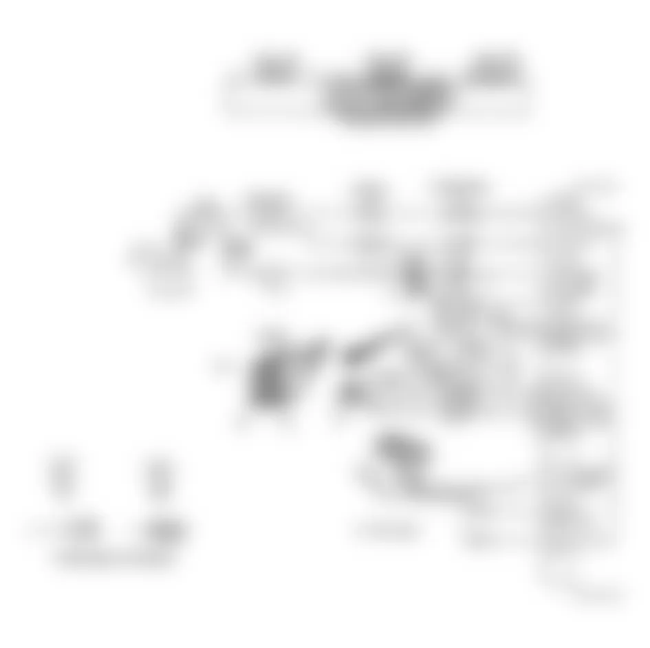
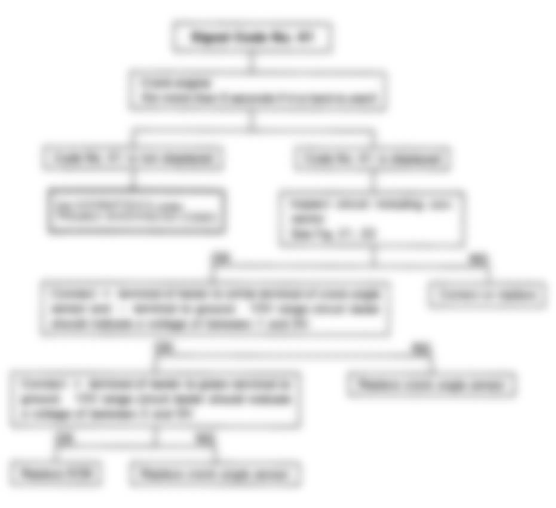
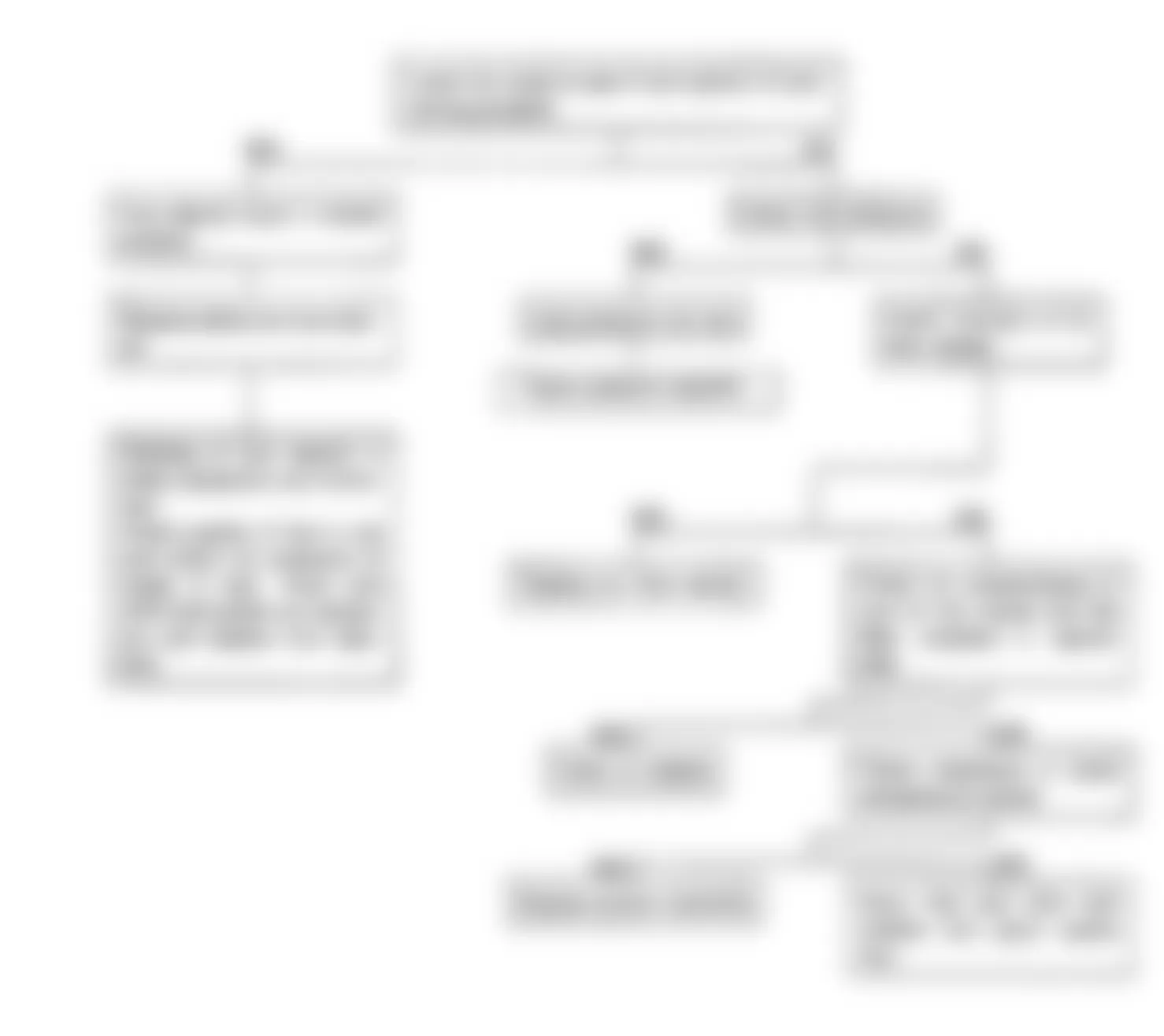
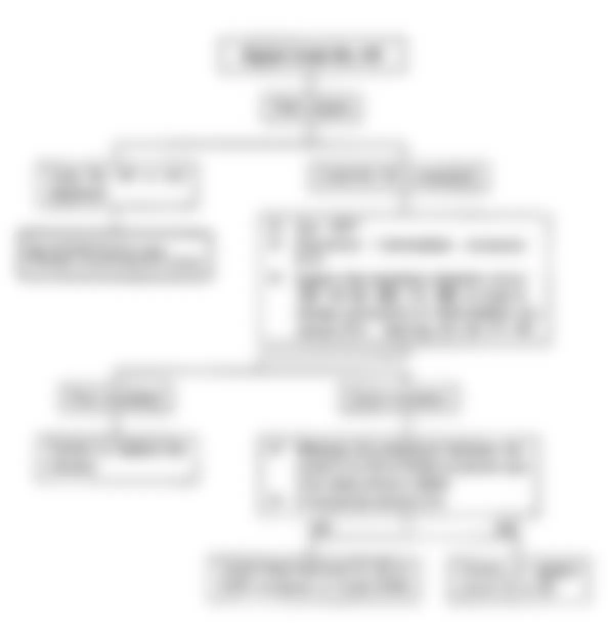
Fig. 9: Isuzu Rodeo LS 1991 - Component Locations - Test No. 3 Flow Chart, Won't Flash Code No. 12
Isuzu Rodeo LS 1991 - CODE 12 - SYSTEM NORMAL
Code No. 12 is always displayed when the key is ON and the engine is not running and it only means that the engine is not running. This code No. 12 is not stored in memory.
NOTE: If the signal code No. 12 only is displayed when the function key is operated after clearing the memory, it indicates that the ECM electrical circuits and self diagnosis system are functioning normally.
Isuzu Rodeo LS 1991 - CODE 13 - OXYGEN SENSOR CIRCUIT
Fig. 10: Isuzu Rodeo LS 1991 - Component Locations - Code No. 13 Schematic, System Normal
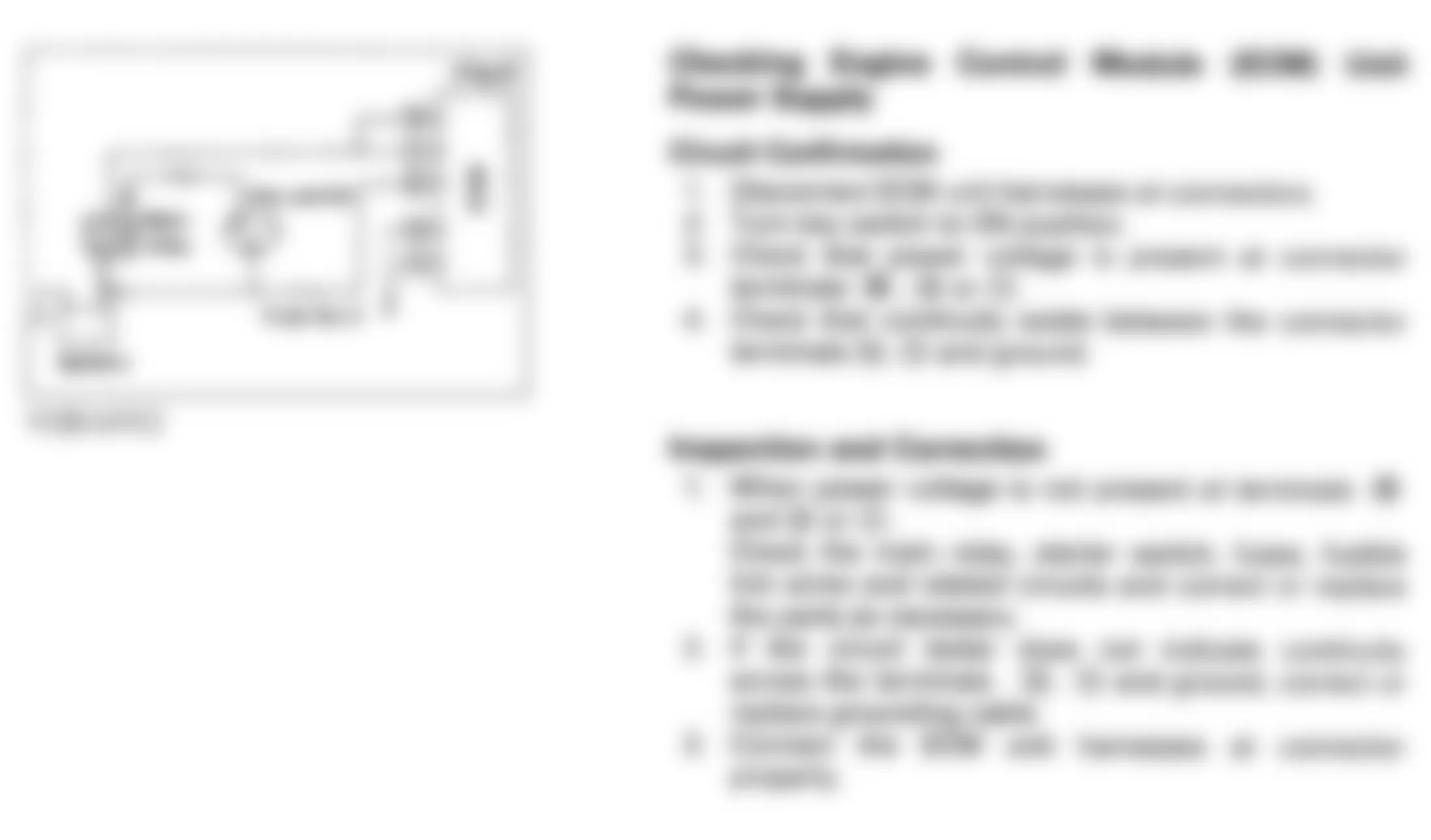
Fig. 11: Isuzu Rodeo LS 1991 - Component Locations - Code No. 13 Component Diagram, System Normal

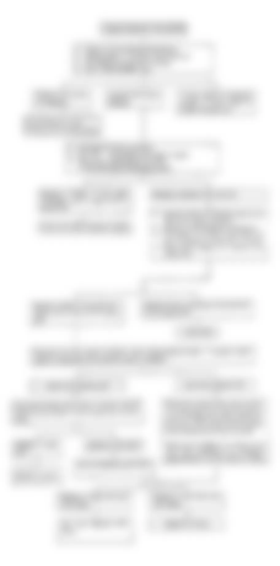
Fig. 12: Isuzu Rodeo LS 1991 - Component Locations - Code No. 13 Flow Chart, System Normal
Isuzu Rodeo LS 1991 - CODE 14, 15 - COOLANT TEMPERATURE SENSOR


Fig. 15: Isuzu Rodeo LS 1991 - Component Locations - Code No. 14 Flow Chart, Shorted CTS Sensor

Fig. 16: Isuzu Rodeo LS 1991 - Component Locations - Code No. 15 Flow Chart, Open CTS Sensor
Isuzu Rodeo LS 1991 - CODE 21 - THROTTLE VALVE SWITCH (IDLE & FULL THROTTLE)
Isuzu Rodeo LS 1991 THROTTLE VALVE SWITCH RESISTANCE
Accelerator Pedal Position Continuity I - P (Ohms) Continuity P - F (Ohms) Not Depressed 0 Infinity Slightly Depressed Infinity Infinity Fully Depressed Infinity 0
Fig. 17: Isuzu Rodeo LS 1991 - Component Locations - Code No. 21 Schematic, Throttle Valve Switch

Fig. 18: Isuzu Rodeo LS 1991 - Component Locations - Code No. 21 Connector, Throttle Valve Switch

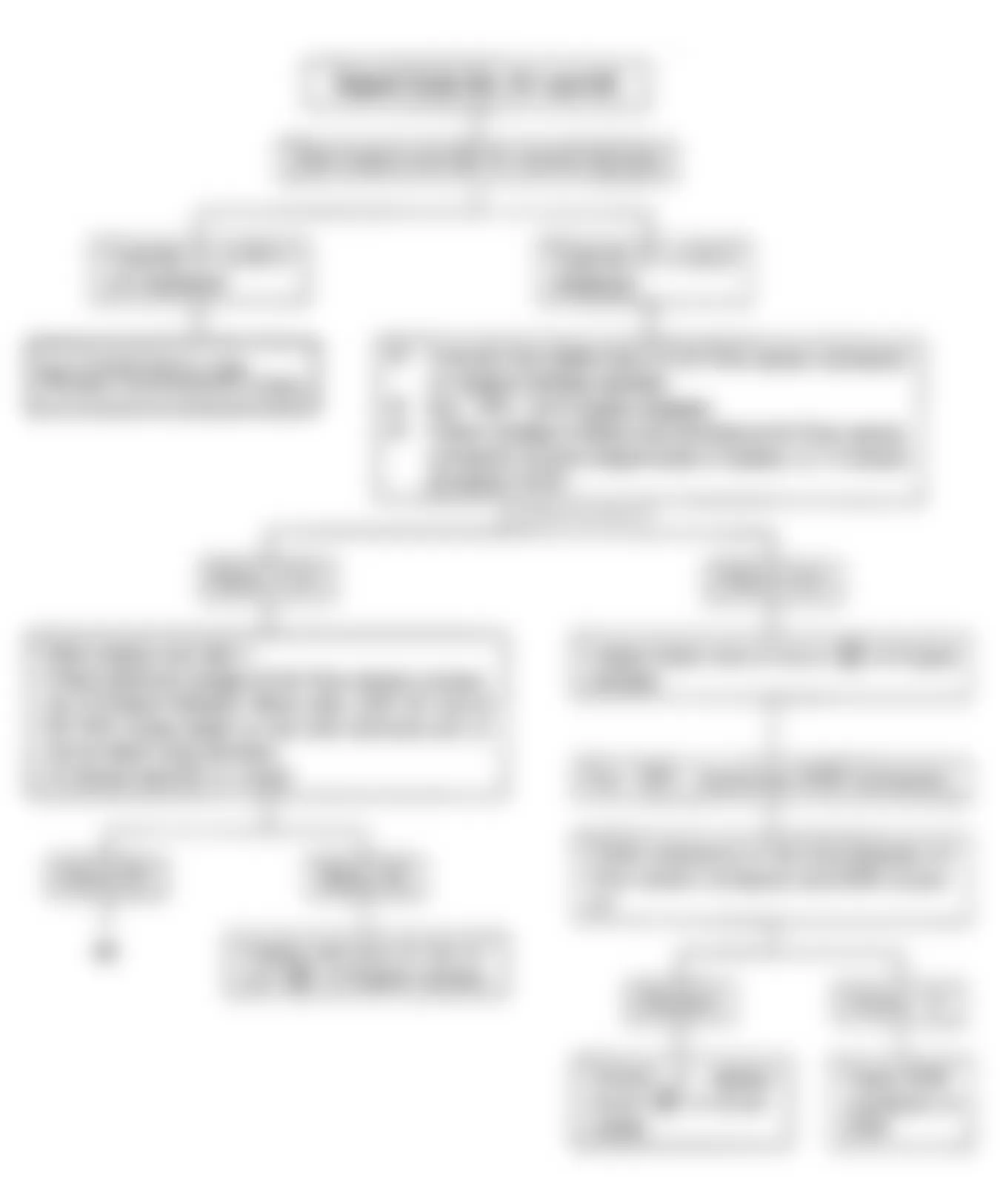
Fig. 19: Isuzu Rodeo LS 1991 - Component Locations - Code No. 21 Flow Chart, Throttle Valve Switch
Isuzu Rodeo LS 1991 - CODE 22 - STARTER SIGNAL
NOTE: Starter relay is located in relay box, in engine compartment.
Fig. 20: Isuzu Rodeo LS 1991 - Component Locations - Code No. 22 Schematic, Starter Signal

Fig. 21: Isuzu Rodeo LS 1991 - Component Locations - Code No. 22 Flow Chart, Starter Signal
Isuzu Rodeo LS 1991 - CODE 23, 35, 54 - POWER TRANSISTOR CIRCUIT Diagnostic Aid
If code 23 is displayed, there should be no continuity between circuit 5 and ground. If code 35 is displayed, there should be continuity between STAY of power transistor and intake manifold. If code 54 is displayed, there should be continuity between circuit 10 and ground.

Isuzu Rodeo LS 1991 - CODE 25, 53 - PRESSURE REGULATOR VSV Diagnostic Aid
If code 25 is displayed, voltage between BLACK/WHITE wire and ground should be 12 volts and resistance between LIGHT GRAY/YELLOW wire and circuit No. 4 should be zero. If code 53 is displayed, resistance between circuits No. 9 and 10 and ground should be zero.


Isuzu Rodeo LS 1991 - CODE 26, 27 - CANISTER PURGE VSV
Fig. 27: Isuzu Rodeo LS 1991 - Component Locations - Code No. 26, 27 Schematic, Canister Purge VSV

Fig. 28: Isuzu Rodeo LS 1991 - Component Locations - Code No. 26, 27 Connector, Canister Purge VSV

Fig. 29: Isuzu Rodeo LS 1991 - Component Locations - Code No. 26, 27 Flow Chart, Canister Purge VSV
Isuzu Rodeo LS 1991 - CODE 32 - EGR SYSTEM MALFUNCTION Specified Reappearance Pattern
- Run engine at idle condition, at normal operating temperature.
- Keep at idle for more than 10 seconds, with vehicle stopped
- Drive vehicle at just over 10 MPH. Accelerate quickly to more than 30 MPH (must reach 30 MPH within 10 seconds of starting acceleration).
- Within 30 seconds, decelerate safely to a complete stop. See Fig. 30 .
- Repeat above procedure 2) through 4) several times.
Fig. 30: Isuzu Rodeo LS 1991 - Component Locations - Code No. 32 Acceleration Chart
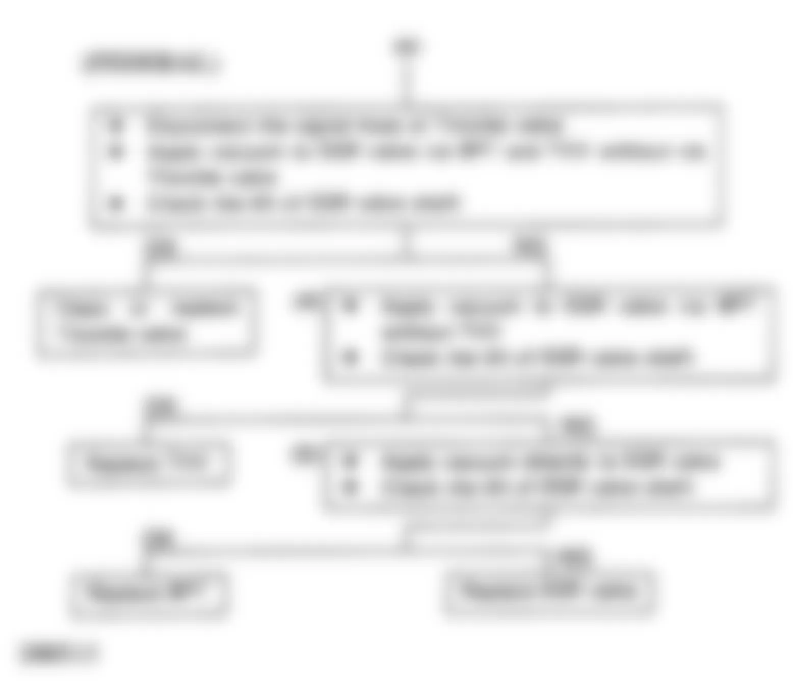
Isuzu Rodeo LS 1991 - CODE 33 - FUEL INJECTOR CIRCUIT (OPEN OR GROUNDED) Diagnostic Aid
- Check circuit 21 with key ON, engine stopped. Measure the voltage between terminal 75 and battery (-) at Dropping Resistor connector. See Fig. 35 . Voltage should be more than 8 volts.
- Measure the voltage difference between battery (+) and each injector at Dropping Resistor connector. Voltage should be almost zero volts.
- Measure the voltage difference between battery (-) and each injector at Dropping Resistor connector. Voltage should be more than 8 volts.
- With key OFF, disconnect all ECM connectors. Then with key ON, measure the voltage between battery (+) and injector terminals.
- Measure the voltage of injector terminals No. 1 and 2 at ECM connector (10 pin).
Fig. 34: Isuzu Rodeo LS 1991 - Component Locations - Code No. 33 Schematic, Fuel Injector Circuit

Fig. 35: Isuzu Rodeo LS 1991 - Component Locations - Code No. 33 Connector, Fuel Injector Circuit

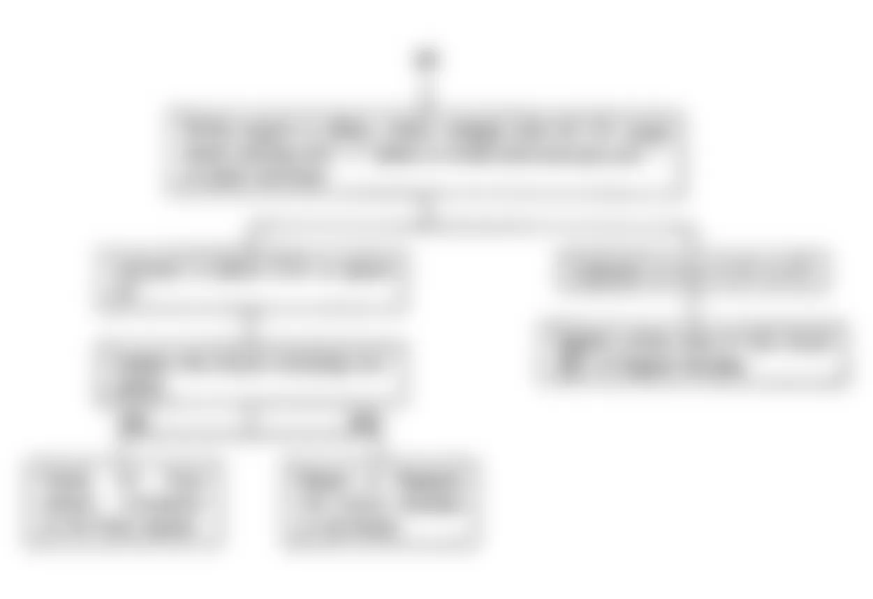
Fig. 36: Isuzu Rodeo LS 1991 - Component Locations - Code No. 33 Flow Chart, Fuel Injector Circuit
Isuzu Rodeo LS 1991 - CODE 34 - EGR GAS TEMPERATURE SENSOR Diagnostic Aid
Resistance between ECM terminal 26 and GRY/YEL and between ECM terminal 38 and BLK should be zero ohms. Resistance between ECM terminal 38 and ground should be zero ohms. Resistance between ECM terminals 11 and 20 and ground should be zero.


Isuzu Rodeo LS 1991 - CODE 35 - POWER TRANSISTOR CIRCUIT
See Code No. 23.
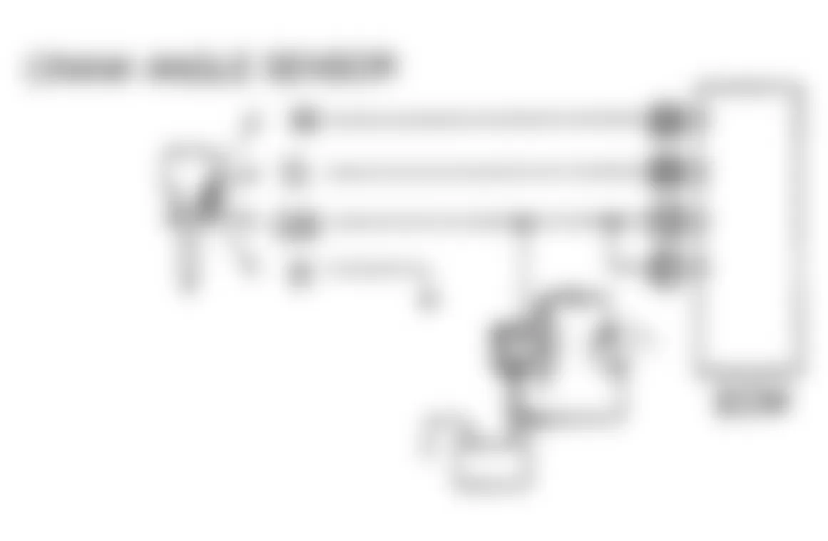
Isuzu Rodeo LS 1991 - CODE 41 - CRANK ANGLE SENSOR SIGNAL
NOTE: Wire colors may vary. See WIRING DIAGRAMS article in the ENGINE PERFORMANCE Section..
Isuzu Rodeo LS 1991 - Diagnostic Aid
- Disconnect crank angle sensor harnesses at crank angle sensor connector.
- Disconnect all connectors at ECM.
- Turn ignition ON. Measure resistance between terminals 34 and WHITE, 35 and GREEN and BLACK and ground. Resistance should be zero.
- Measure voltage between GREEN/BLACK and ground. Voltage should be 10-14 volts.
- When circuit is found to be in normal condition, replace distributor assembly.

Isuzu Rodeo LS 1991 - CODE 43, 65 - THROTTLE VALVE SWITCH
Isuzu Rodeo LS 1991 THROTTLE VALVE SWITCH RESISTANCE
Accelerator Pedal Position Continuity I - P (Ohms) Continuity P - F (Ohms) Not Depressed 0 Infinity Slightly Depressed Infinity Infinity Fully Depressed Infinity 0


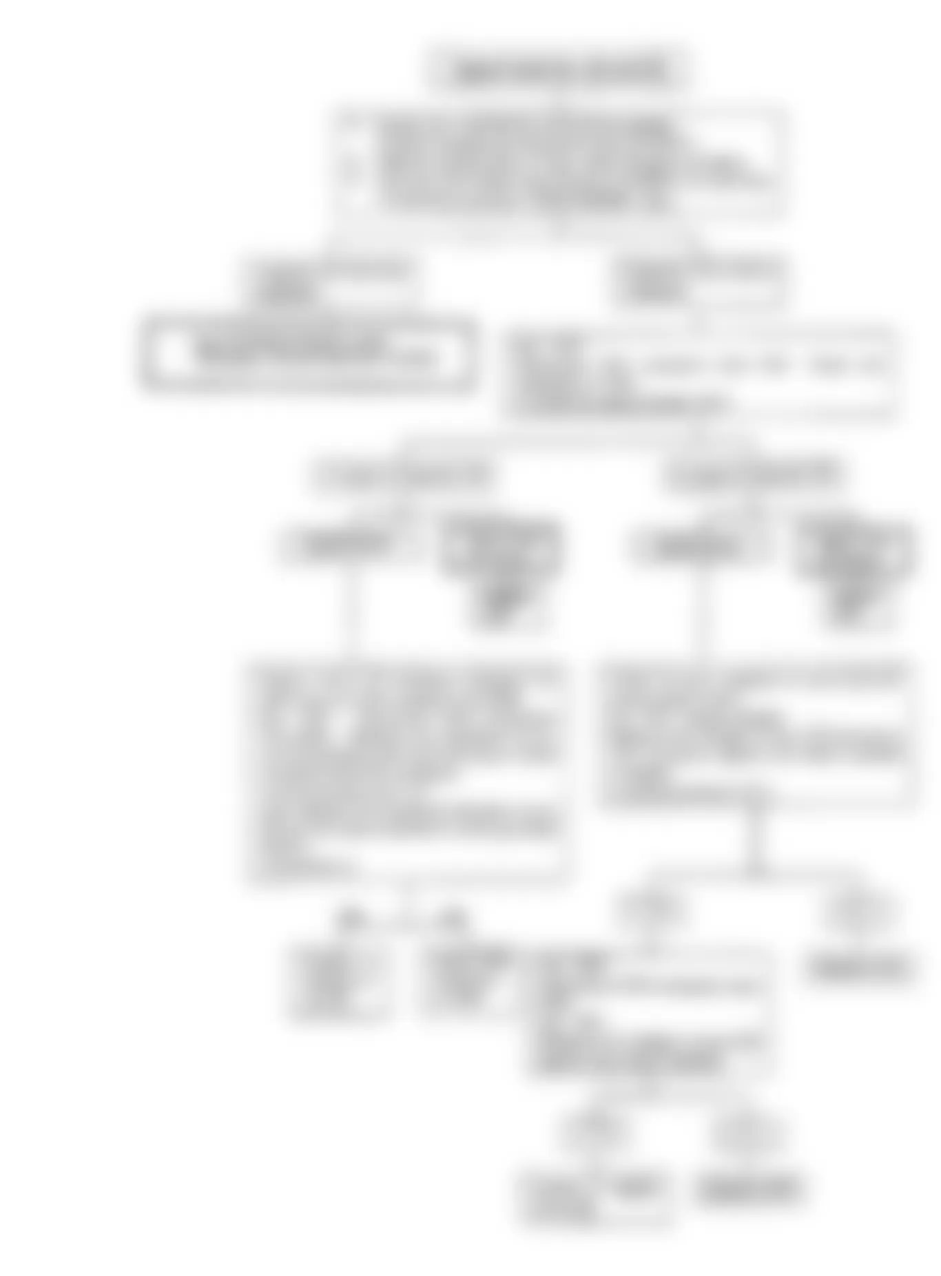
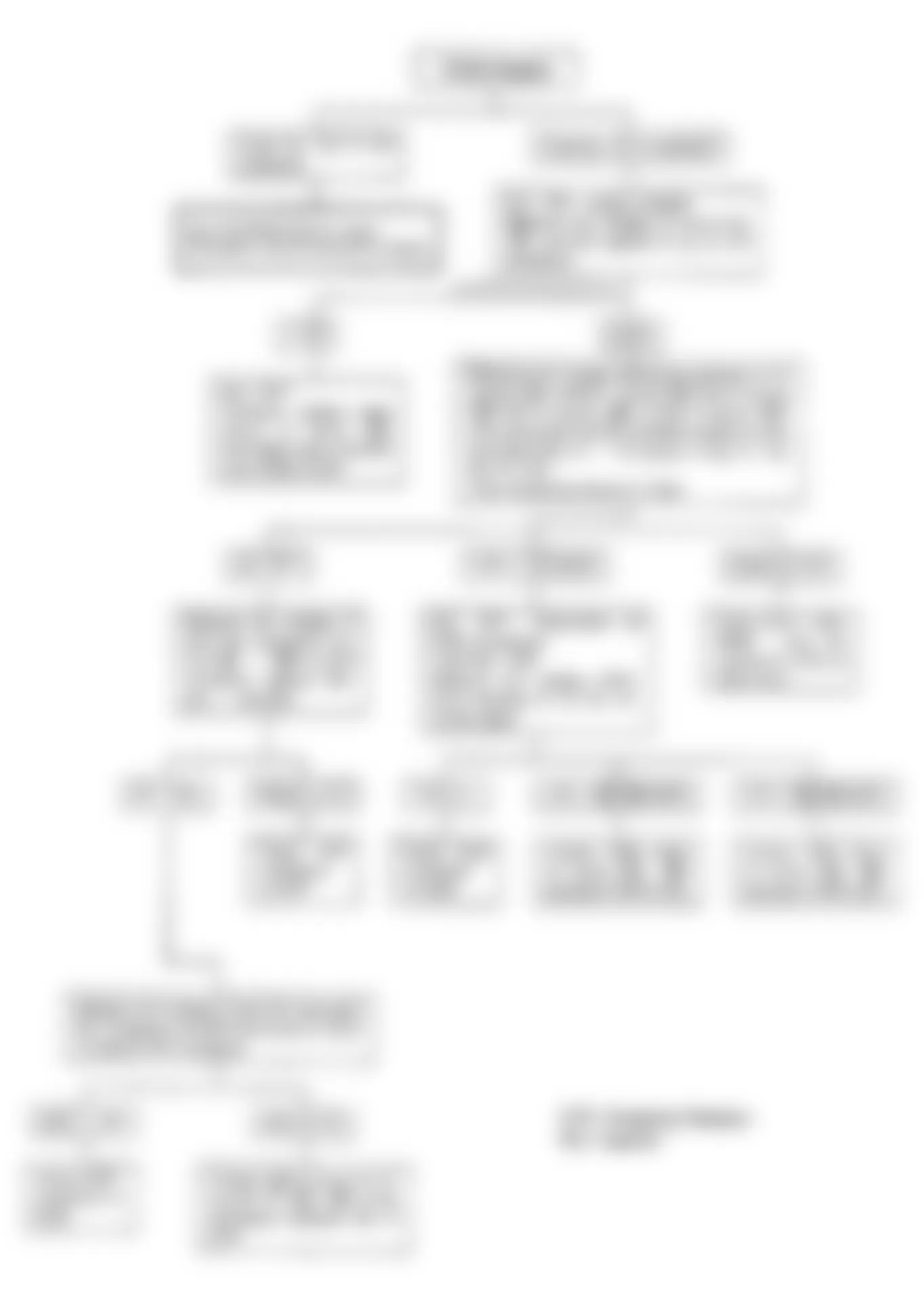
Isuzu Rodeo LS 1991 - CODE 44, 45 - OXYGEN SENSOR-LEAN/RICH FUEL MIXTURE

Isuzu Rodeo LS 1991 - Fuel Metering Lean-Faulty Inspection Procedure
Fig. 50: Isuzu Rodeo LS 1991 - Component Locations - Fuel Metering Lean Fault Flow Chart
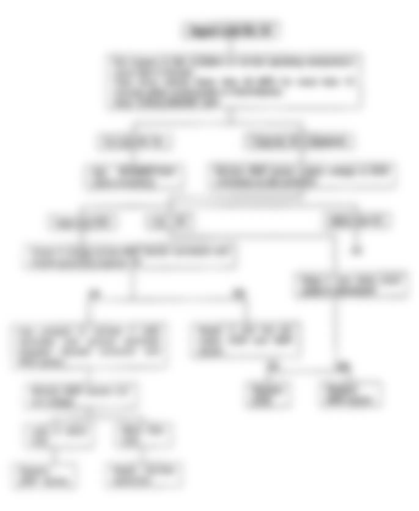
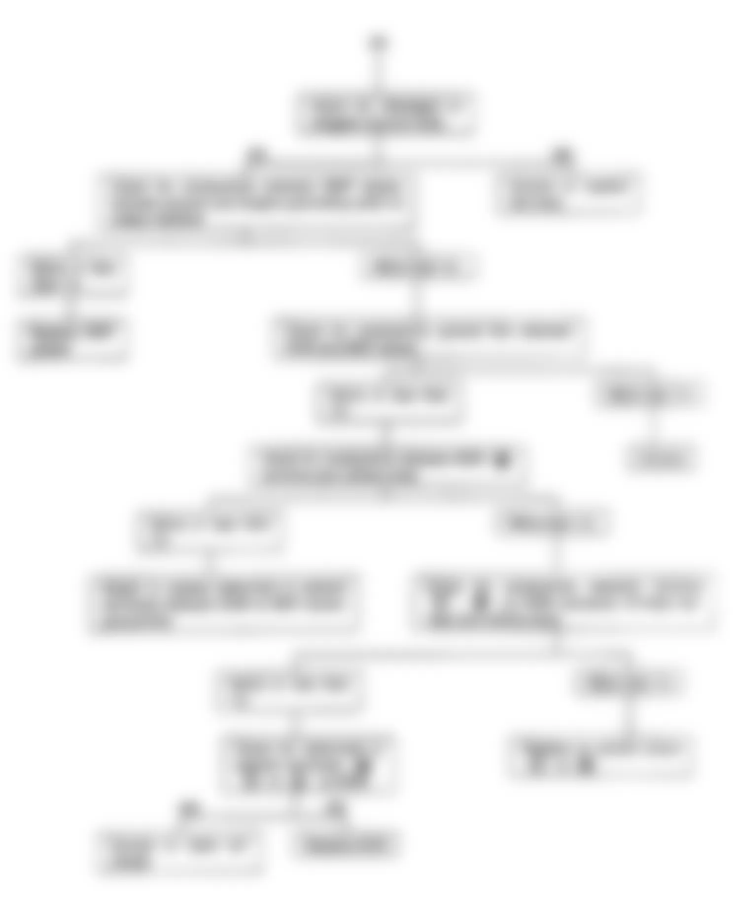
Isuzu Rodeo LS 1991 - Fuel Metering Rich Faulty Inspection Procedure
Fig. 51: Isuzu Rodeo LS 1991 - Component Locations - Fuel Metering Rich Fault Schematic

Fig. 52: Isuzu Rodeo LS 1991 - Component Locations - Fuel Metering Rich Fault Flow Chart

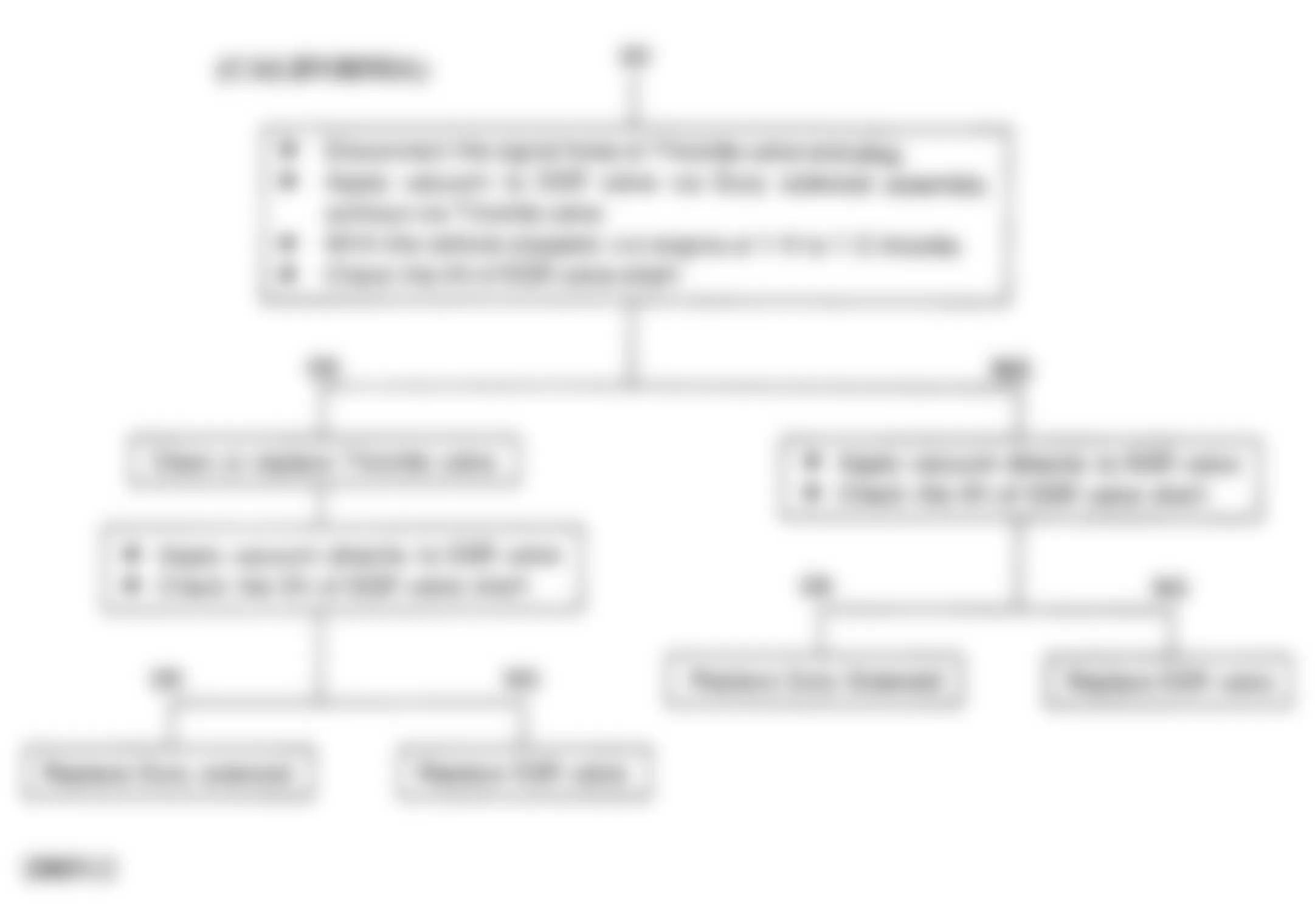
Isuzu Rodeo LS 1991 - CODE 51, 52 - FAULTY ECM RAM/ROM Circuit Connections
- Disconnect the control unit harnesses at connector and check for proper connections at terminals.
- Regardless of terminal conditions, road test the vehicle with all the harnesses reconnected at the connector.
- Obtain display of trouble code and see if the trouble has been corrected. If the trouble persists, replace the ECM.
Isuzu Rodeo LS 1991 - CODE 53 - PRESSURE REGULATOR VSV
See Code No. 25.
Isuzu Rodeo LS 1991 - CODE 54 - POWER TRANSISTOR CIRCUIT
See Code No. 23.
Isuzu Rodeo LS 1991 - CODE 61, 62 - AIRFLOW SENSOR SIGNAL Inspection Of Airflow Sensor
Uncover the rubber boot on the air flow sensor side of the harness connector. Check resistance an voltage of terminals. See AIRFLOW SENSOR SIGNAL table.
Isuzu Rodeo LS 1991 AIRFLOW SENSOR SIGNAL
Wiring Ignition Switch Volts Resistance (Ohms) Red-Ground ON 10-14 N/A Red-Ground ON Below 0.2 N/A White-Ground ON (While breathing) 0.5-1.5 N/A Black-Ground ON/OFF Below 0.2 0
Isuzu Rodeo LS 1991 CIRCUIT WIRING RESISTANCE
Wiring Resistance (Ohms) W To Circuit 31 0 W To Ground Infinity R To Circuit 32 0 R To Ground Infinity B to Circuit 40 0

Isuzu Rodeo LS 1991 - CODE 63 - VEHICLE SPEED SENSOR SIGNAL
Code 63 may be displayed even if the system is normal if the vehicle is used under the following conditions:
- A/T; In "D" range, while depressing the brake pedal, the accelerator pedal is depressed over 1/2 throttle for more than 3 seconds
- M/T; Under the severe climbing conditions, keep the vehicle stopped while the accelerator pedal depressed over 1/2 throttle for more than 3 seconds
Isuzu Rodeo LS 1991 - Sensor & Equipment
- Connect a circuit tester between the control unit harness connector terminal 41 and ground.
- Disconnect speedometer cable at transmission end and turn the inner cable slowly.
- If the tester indicates continuity and open circuit condition alternately as the cable is turned, the car speed sensor and circuit are operating normally
Isuzu Rodeo LS 1991 - Wiring Circuits
Check resistance between YELLOW and Circuit 41, See Fig. 56 , reading should be zero ohms. Check resistance between BLACK and ground, there should be infinite resistance.
Isuzu Rodeo LS 1991 - Car Speed Sensor
- Remove the speedometer assembly.
- Connect the leads of a circuit tester across terminals 1 and 2 at rear face of the meter assembly. See Fig. 57 .
- Turn the inner shaft slowly and check that the tester indicates a continuity and open circuit condition alternately. If speed sensor is inoperative, replace speedometer assembly.

Fig. 57: Isuzu Rodeo LS 1991 - Component Locations - Code No. 63 Speed Sensor Check
Isuzu Rodeo LS 1991 - CODE 64 - FUEL INJECTOR CIRCUIT (ECM TRANSISTOR)


Isuzu Rodeo LS 1991 - CODE 65 - THROTTLE VALVE SWITCH
See Code No. 43.
Isuzu Rodeo LS 1991 - SUMMARY
If no hard fault codes (or only pass codes) are present, driveability symptoms exist or intermittent codes exist, proceed to H - EFI TESTS W/O CODES article in the ENGINE PERFORMANCE Section for diagnosis by symptom (i.e. ROUGH IDLE, NO START, etc.) or intermittent diagnosis procedures.