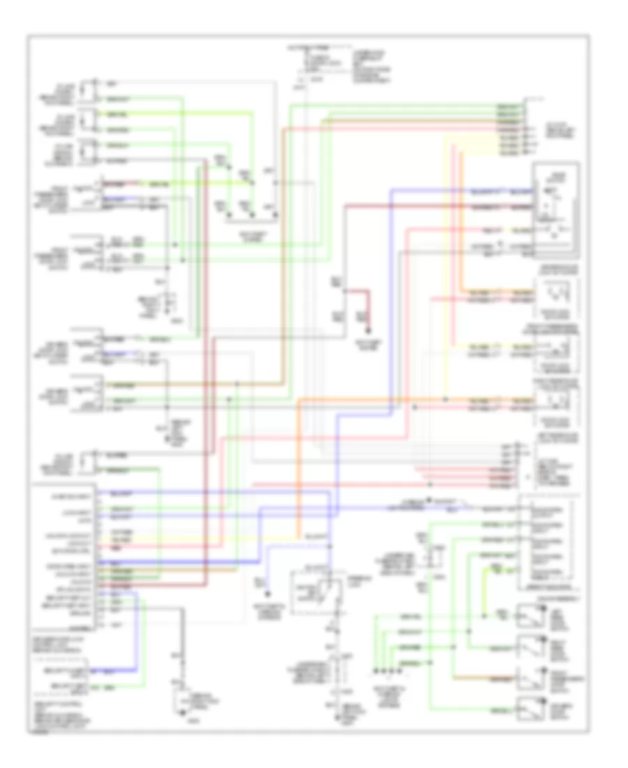
AIR CONDITIONING
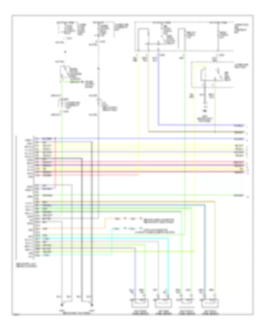
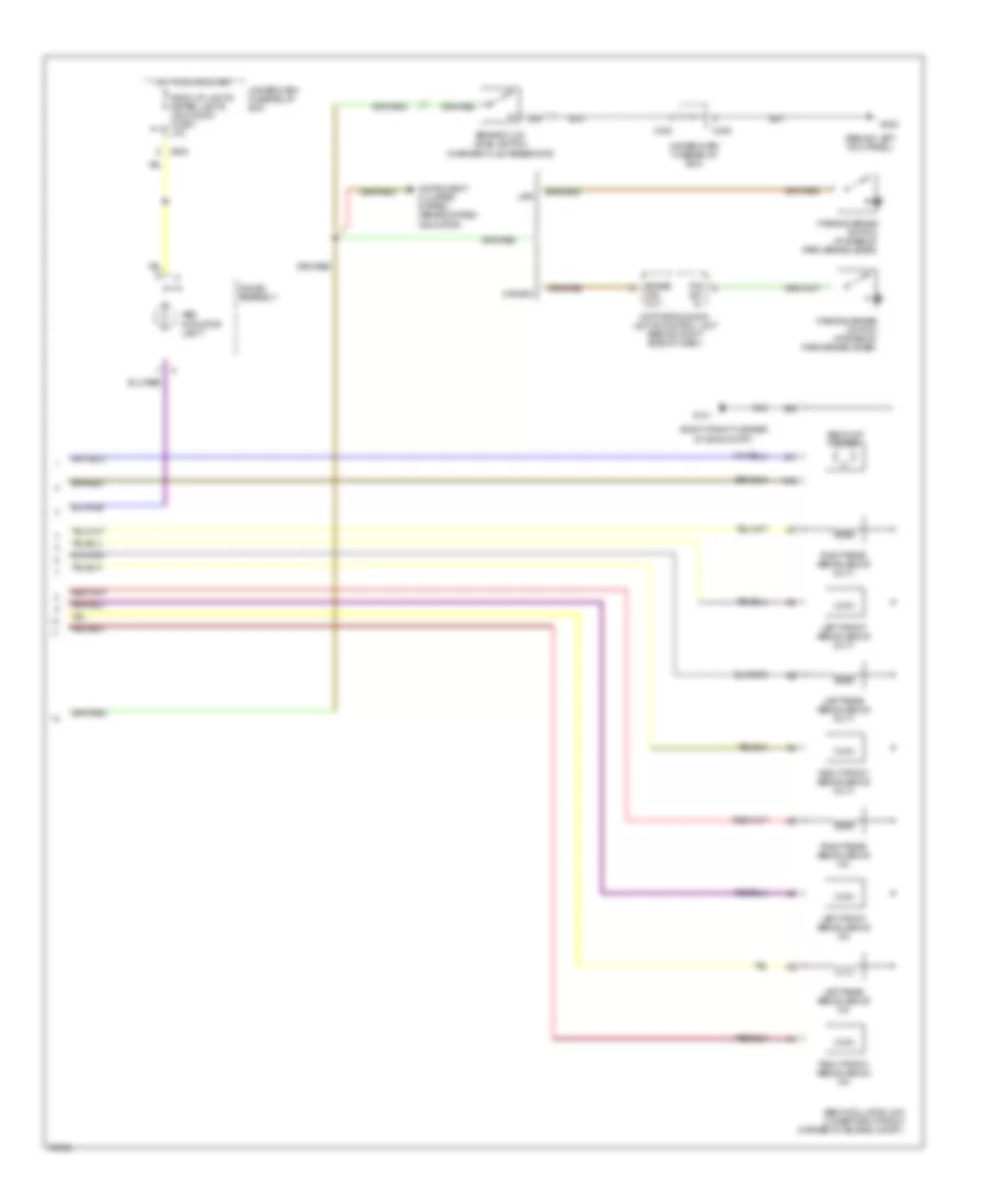
Automatic A/C Wiring Diagram for Acura 2.5TL 1998
 https://portal-diagnostov.com/license.html
Automotive Electricians Portal FZCO
Automotive Electricians Portal FZCO
https://portal-diagnostov.com/license.html
https://portal-diagnostov.com/license.html
Automotive Electricians Portal FZCO
Automotive Electricians Portal FZCO
List of elements for Automatic A/C Wiring Diagram for Acura 2.5TL 1998:
- (left front corner of engine compartment)
- (left kick panel)
- (on bracket)
- (right
- (right kick
- 5v ref
- A/c compressor clutch
- A/c compressor clutch relay (on left rear corner of engine compartment, mounted on bracket)
- A/c on output
- A/c pres- sure switch (on left front of engine compt)
- A19
- Acc
- Acs
- Air mix cool
- Air mix hot
- Air mix pot
- Air mixture control motor (behind left side of glove box)
- Air temp input
- Battery
- Blower motor (behind left side of glove box)
- Blower motor high relay (behind left side of glove box, mounted on bracket)
- Blower motor relay (above right kick panel, in underdash relay box)
- Blw mot hi relay
- Blwr mtr fbck
- C216
- C217
- C218
- C406
- Climate control unit
- Condenser fan motor
- Condenser fan relay (on left side of radiator, mounted on bracket)
- Conn a
- Conn b
- D11
- Defogger system
- Ect sens
- Engine control module (ecm) (below right front footrest)
- Engine coolant temperature (ect) sensor (on center front of engine, on coolant outlet)
- Evap temp input
- Evaporator temp sensor (behind left side of glove box)
- Fan c
- Fresh
- Fuse 10a
- Fuse 20a
- Fuse 30a
- Fuse 7.5a
- G100
- G112 (left side of engine)
- G200
- G203 (right kick panel)
- Ground
- Heater valve control solenoid valve (on left rear of engine compartment, on firewall in control box)
- Hot at all times
- Hot in on
- Hot in on or start
- Htr valve ctrl
- Ignition
- Illum +
- Illum -
- In car temp input
- In car temp sensor (behind left side of dash)
- Interior lights system
- J/c (c419) (above left kick panel)
- J/c (c444) (below right side of dash, taped to harness)
- Kick panel) g203
- Mode control motor (behind left side of dash, right side of driver's footwell)
- Mode defrost
- Mode heat
- Mode heat/def
- Mode heat/vent
- Mode vent
- Outside air temp sensor (forward of radiator)
- Panel) g203
- Pnk
- Power trans ctrl
- Power transistor (behind right side of dash, on plenum)
- Radiator fan control module (behind glove box, behind keyless door lock control unit)
- Radiator fan motor
- Radiator fan relay (on left side of radiator mounted on bracket)
- Radiator fan switch a
- Radiator fan switch b
- Rear defog sw
- Recirculate
- Recirculation control motor (behind left side of dash)
- Red
- Relay ctrl
- Sensor ground
- Sg1
- Sunlight sens
- Sunlight sensor (on top left side of dash)
- Sw a input
- Sw b input
- Underdash fuse/relay box (behind left side of dash)
- Underhood fuse/relay box (on right side of engine compartment)
- Vehicle speed sensor (vss) (on left side of transaxle)
- Vss input
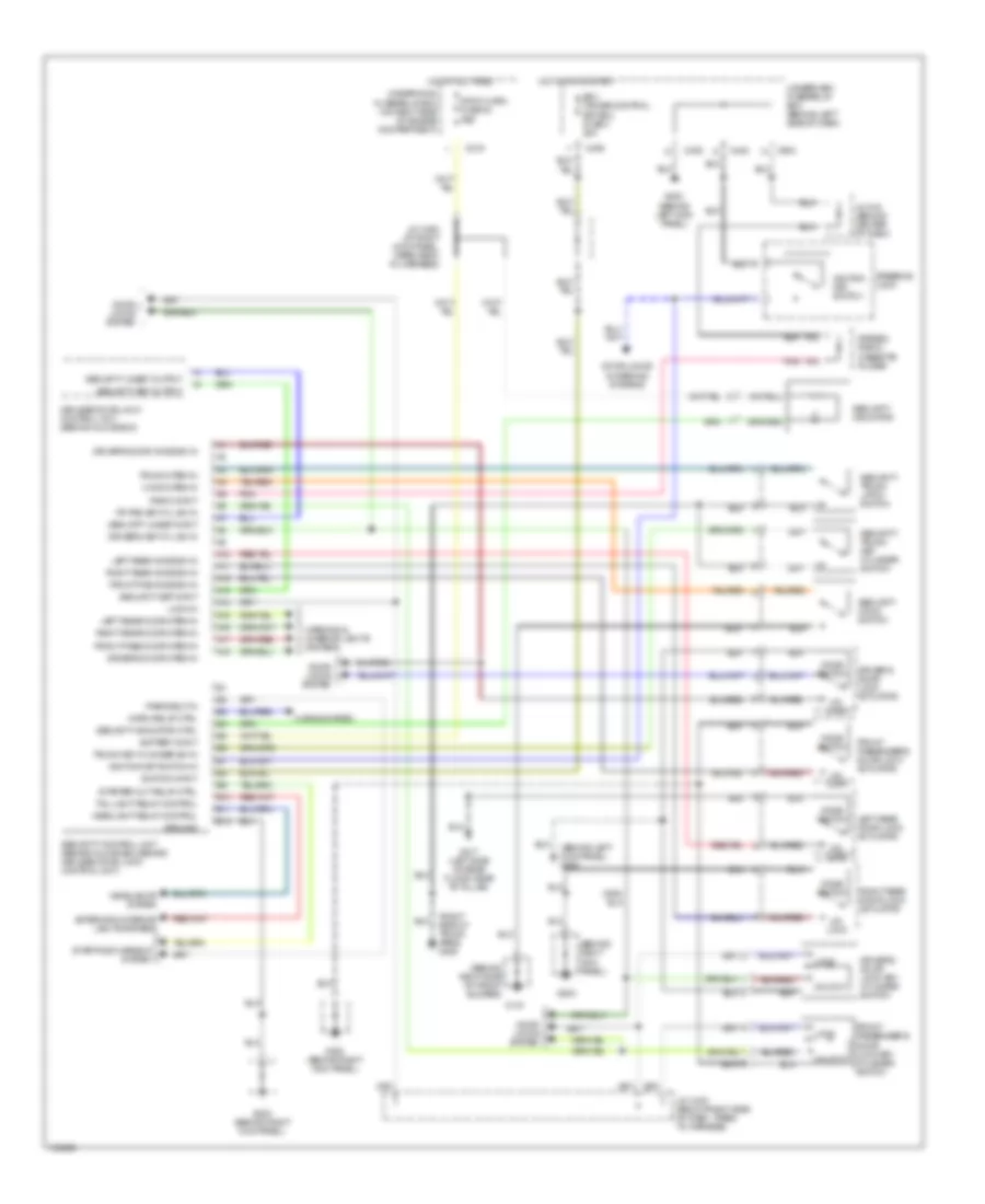
ANTI-LOCK BRAKES
Anti-lock Brakes Wiring Diagram (1 of 2) for Acura 2.5TL 1998
 https://portal-diagnostov.com/license.html
Automotive Electricians Portal FZCO
Automotive Electricians Portal FZCO
https://portal-diagnostov.com/license.html
https://portal-diagnostov.com/license.html
Automotive Electricians Portal FZCO
Automotive Electricians Portal FZCOList of elements for Anti-lock Brakes Wiring Diagram (1 of 2) for Acura 2.5TL 1998:
- (behind right kick panel)
- (in front console, behind ashtray)
- A10
- A11
- A12
- A4
- Abs b1 fuse 46 20a
- Abs control unit (behind glove box)
- Abs fail- safe relay
- Abs motor fuse 45 30a
- Abs pump motor relay
- Abs unit fuse 48 7.5a
- B10
- B11
- B12
- B13
- B14
- B15
- B16
- B17
- B18
- B19
- B20
- B21
- B22
- Brake switch (on brake pedal support)
- C208
- C209
- C219
- C406
- Cruise control system
- Data link connector
- Dlc
- Fl-in
- Fl-out
- Flw (+)
- Flw (-)
- Fr-in
- Fr-out
- Frw (+)
- Frw (-)
- Fsr
- G203
- G203 (behind right kick panel)
- Gnd1
- Gnd2
- Gnd3
- Gnd4
- Heater control relay fuse 7 7.5a
- Hot at all times
- Hot in on
- Ig2
- J/c c444 (below right side of dash)
- Left front wheel sensor
- Left rear wheel sensor
- Mck
- Park
- Pmr
- Right front wheel sensor
- Right rear wheel sensor
- Rl-in
- Rl-out
- Rlw (+)
- Rlw (-)
- Rr-in
- Rr-out
- Rrw (+)
- Rrw (-)
- Scs
- Service check connector (behind right side of dash)
- Stop
- Stop, horn fuse 30 20a
- Under- hood fuse/ relay box
- Under-dash fuse/relay box
- Under-dash relay box
- Under-hood abs fuse/relay box
- Warn 1
- Warn 2
Anti-lock Brakes Wiring Diagram (2 of 2) for Acura 2.5TL 1998
 https://portal-diagnostov.com/license.html
Automotive Electricians Portal FZCO
Automotive Electricians Portal FZCO
https://portal-diagnostov.com/license.html
https://portal-diagnostov.com/license.html
Automotive Electricians Portal FZCO
Automotive Electricians Portal FZCOList of elements for Anti-lock Brakes Wiring Diagram (2 of 2) for Acura 2.5TL 1998:
- (behind left kick panel)
- (right front corner of eng compt)
- A10
- Abs indicator light
- Abs modulator unit (lower right front corner of engine compt.)
- Abs pump motor
- Back-up lights meter lights (sun roof) fuse 1 10a
- Brake fluid level switch (in brake fluid reservoir)
- Brake ind. out.
- C402
- C405
- C603
- Canada
- Daytime running lights control unit (behind right side of dash)
- G101
- G200
- Gauge assembly
- Hot in on or start
- Instrument cluster system (brake system indicator)
- Left front abs solenoid (in)
- Left front abs solenoid (out)
- Left rear abs solenoid (in)
- Left rear abs solenoid (out)
- P.b. sw. in.
- Parking brake switch (at base of park brake lever)
- Right front abs solenoid (in)
- Right front abs solenoid (out)
- Right rear abs solenoid (in)
- Right rear abs solenoid (out)
- Under-dash fuse/relay box
- Usa
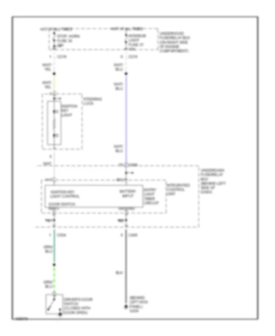
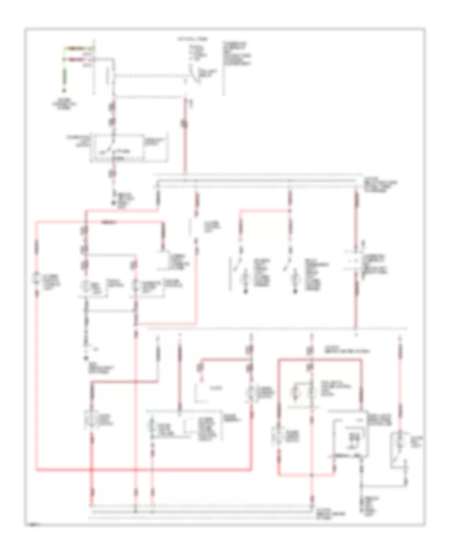
ANTI-THEFT
Anti-theft Wiring Diagram for Acura 2.5TL 1998
 https://portal-diagnostov.com/license.html
Automotive Electricians Portal FZCO
Automotive Electricians Portal FZCO
https://portal-diagnostov.com/license.html
https://portal-diagnostov.com/license.html
Automotive Electricians Portal FZCO
Automotive Electricians Portal FZCOList of elements for Anti-theft Wiring Diagram for Acura 2.5TL 1998:
- (behind left kick panel) g200
- (behind right kick panel)
- (behind right side of front bumper)
- (right side of trunk area) g405
- A10
- A11
- A12
- A13
- A14
- A15
- A16
- A17
- A18
- B10
- B11
- B12
- Battery input
- C219
- C402
- C405
- C406
- C603
- Door locks & warning systems
- Door locks system
- Driver's door knob sw in
- Driver's door lock actuator
- Driver's door lock key cylinder switch
- Driver's door open in
- Driver's key cyl sw in
- Ecu cruise control eat ecu fuse 4 20a
- Exterior & interior lights systems
- Fr pas key cyl sw in
- Front pas knob sw in
- Front pass door open in
- Front passenger's door lock actuator
- Front passenger's door lock key cylinder switch
- G101
- G200 (behind left kick panel)
- G203
- G203 (behind right kick panel)
- G317 (left side of rear floor, near "b" pillar)
- Ground
- Headlight relay control
- Headlights system
- Hood open in
- Horn relay ctrl
- Horns system
- Hot at all times
- Hot in on or start
- Ignition input
- Ignition key switch
- Ignition key switch in
- J/c 616 (behind center of dash)
- J/c c430 (below right side of dash, taped to harness)
- J/c c463 (at right kick panel, taped back to harness)
- Keyless door lock control unit (behind glove box)
- Knob switch
- Left rear door lock actuator
- Left rear door open in
- Left rear knob sw in
- Lock
- Lock in
- Park/neut in
- Pnk
- Radio input
- Right rear door lock actuator
- Right rear door open in
- Right rear knob sw in
- Security control unit (behind glove box, behind keyless door lock control unit)
- Security hood switch
- Security indicator
- Security indicator ctrl
- Security set input
- Security set output
- Security trunk key cylinder switch
- Security trunk latch switch
- Security unset input
- Security unset output
- Starter cut relay ctrl
- Starting/charging system
- Steering lock
- Stereo radio/ cassette player
- Stop, horn fuse 30 20a
- Tail light relay control
- Trunk key cylinder sw in
- Trunk open in
- Un- lock
- Underdash fuse/relay box (behind left side of dash)
- Underhood fuse/relay box (on right side of engine compartment)
- Unlock
- Warning & interior lights systems
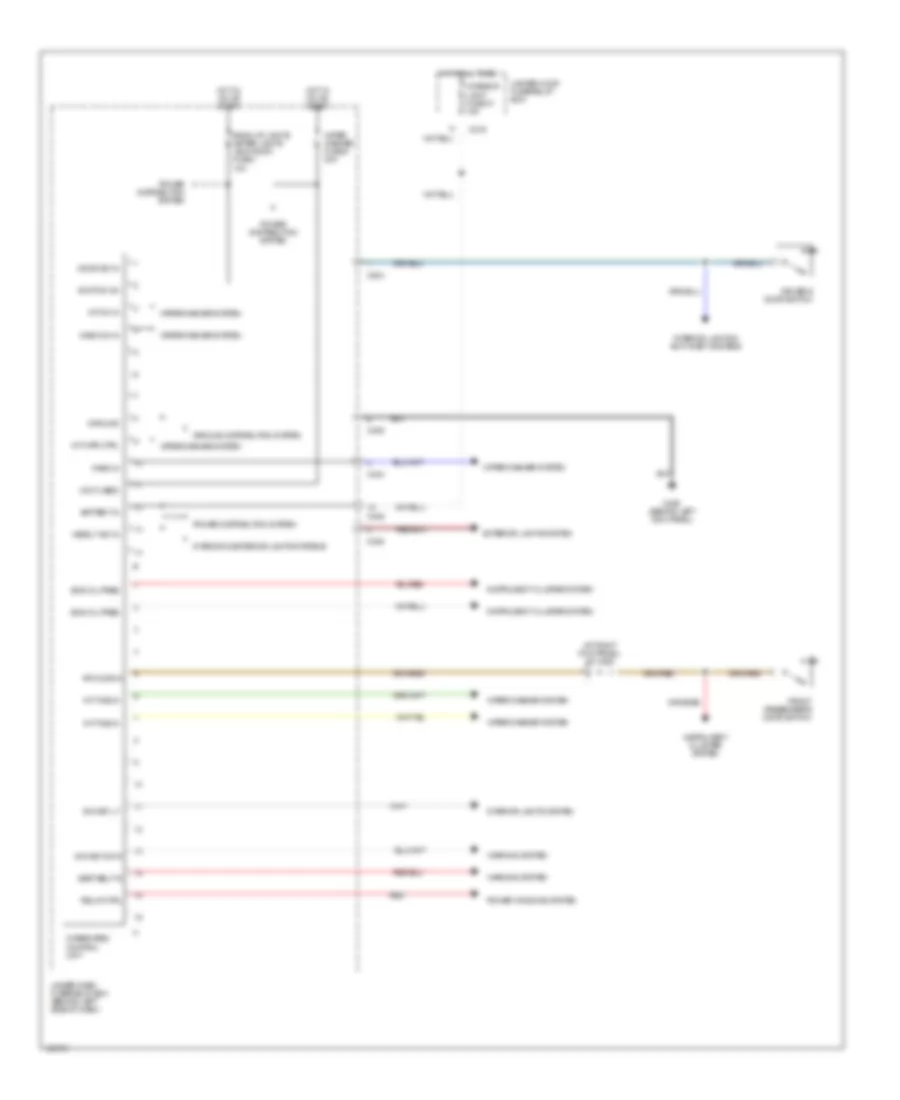
BODY CONTROL MODULES
Integrated Control Unit Wiring Diagram for Acura 2.5TL 1998
 https://portal-diagnostov.com/license.html
Automotive Electricians Portal FZCO
Automotive Electricians Portal FZCO
https://portal-diagnostov.com/license.html
https://portal-diagnostov.com/license.html
Automotive Electricians Portal FZCO
Automotive Electricians Portal FZCOList of elements for Integrated Control Unit Wiring Diagram for Acura 2.5TL 1998:
- (at right kick panel) j/c c463
- (not used)
- Back-up lights meter lights (sun roof) fuse 1 10a
- Battery in
- C216
- C403
- C405
- C406
- C504
- Door sw in
- Driver's door switch
- Eng oil pres
- Exterior lights system
- Front passenger's door switch
- G200 (behind left kick panel)
- Ground
- Ground distribution system
- Headlt sw in
- Hot at all times
- Hot in on or start
- Ign key lt
- Ign key sw in
- Ignition on
- Instrument cluster system
- Int on in
- Int time in
- Int wpr ctrl
- Integrated control unit
- Interior & exterior lights systems
- Interior light fuse 37 15a
- Interior lights & anti-theft systems
- Interior lights system
- Park in
- Power distribution system
- Power windows system
- Red
- Relay ctrl
- Rf door in
- Seat belt in
- Under-dash fuse/relay box (behind left side of dash)
- Under-hood fuse/relay box
- Warning system
- Wash on in
- Wiper washer fuse 6 30a
- Wiper/washer system
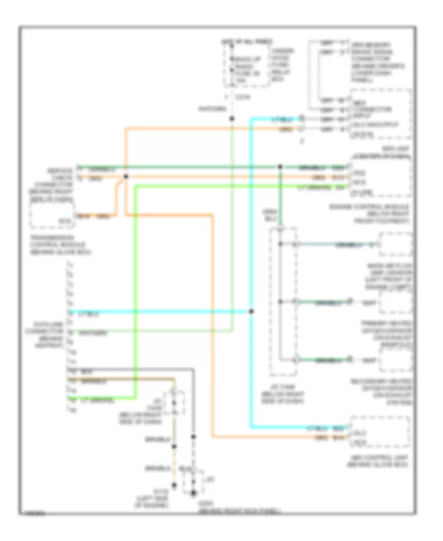
COMPUTER DATA LINES
Computer Data Lines Wiring Diagram for Acura 2.5TL 1998
 https://portal-diagnostov.com/license.html
Automotive Electricians Portal FZCO
Automotive Electricians Portal FZCO
https://portal-diagnostov.com/license.html
https://portal-diagnostov.com/license.html
Automotive Electricians Portal FZCO
Automotive Electricians Portal FZCOList of elements for Computer Data Lines Wiring Diagram for Acura 2.5TL 1998:
- (behind ashtray)
- Abs control unit (behind glove box)
- B14
- B22
- Back up radio fuse 39 10a
- C216
- Connector (behind driver's lower dash panel)
- Connector (behind right side of dash)
- D13
- D22
- Data link connector
- Dlc
- Dlc in/output
- Engine control module (below right front footrest)
- G112 (left side of engine)
- G203 (behind right kick panel)
- Hot at all times
- J/c
- J/c c436 (below right side of dash)
- J/c c444 (below right side of dash)
- K-line
- Mass air flow (maf) sensor (left front of engine compt)
- Mes connector input
- Primary heated oxygen sensor (on exhaust manifold)
- Scs
- Scs in
- Secondary heated oxygen sensor (on exhaust system)
- Service check
- Sg2
- Srs memory erase signal
- Srs unit (center of dash)
- Transmission control module (behind glove box)
- Under- hood fuse/ relay box
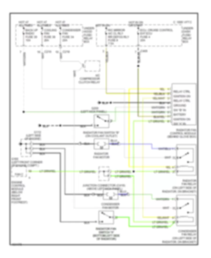
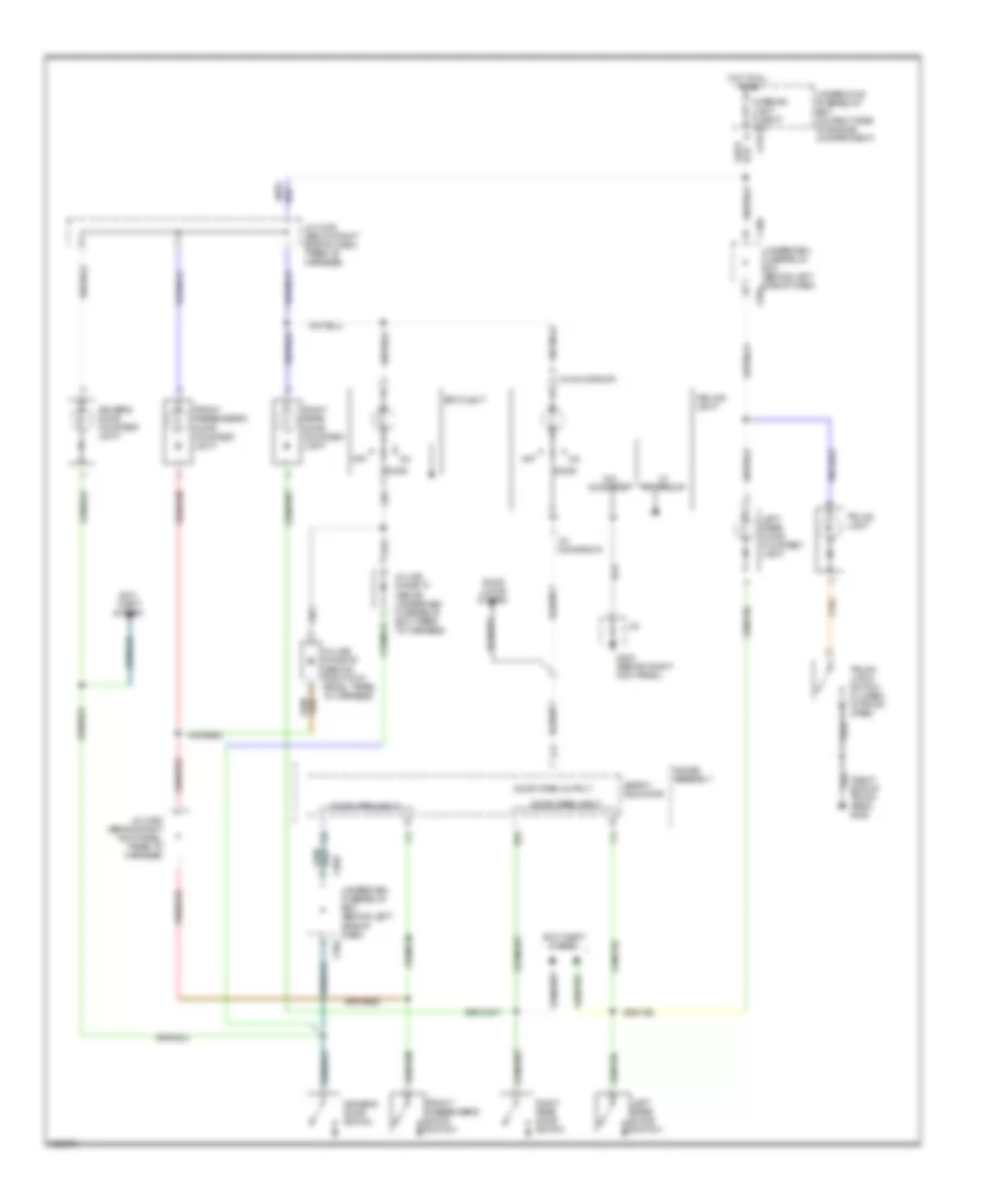
COOLING FAN
Cooling Fan Wiring Diagram for Acura 2.5TL 1998
 https://portal-diagnostov.com/license.html
Automotive Electricians Portal FZCO
Automotive Electricians Portal FZCO
https://portal-diagnostov.com/license.html
https://portal-diagnostov.com/license.html
Automotive Electricians Portal FZCO
Automotive Electricians Portal FZCOList of elements for Cooling Fan Wiring Diagram for Acura 2.5TL 1998:
- (left kick panel)
- (on left side of
- A/c compressor clutch relay
- Back up radio fuse 39 10a
- Battery
- C 1995 vftc
- C216
- C218
- C406
- Condenser fan fuse 34 20a
- Condenser fan motor
- Condenser fan relay
- Cooling fan fuse 38 20a
- Ecu, cruise control eat ecu fuse 4 20a
- Engine control module (below right front footrest)
- Fan c
- G100 (left front corner of engine compt.)
- G112 (left side of engine)
- G200
- Ground
- Hot at all times
- Hot in on
- Hot in on or start
- Ignition on
- Junction connector (c419) (above left kick panel)
- R/c mirror a/c cl rly rr defog rly fuse 8 7.5a
- Radiator fan radiator fan switch "a" switch "a" (bottom left side (bottom left side of radiator) of radiator)
- Radiator fan control module (behind glove box)
- Radiator fan motor
- Radiator fan relay
- Radiator fan switch "b" (on coolant outlet)
- Radiator, on bracket)
- Relay ctrl
- Sw "a" in
- Sw "b" in
- Under- dash fuse/ relay box
- Under- hood fuse/ relay box
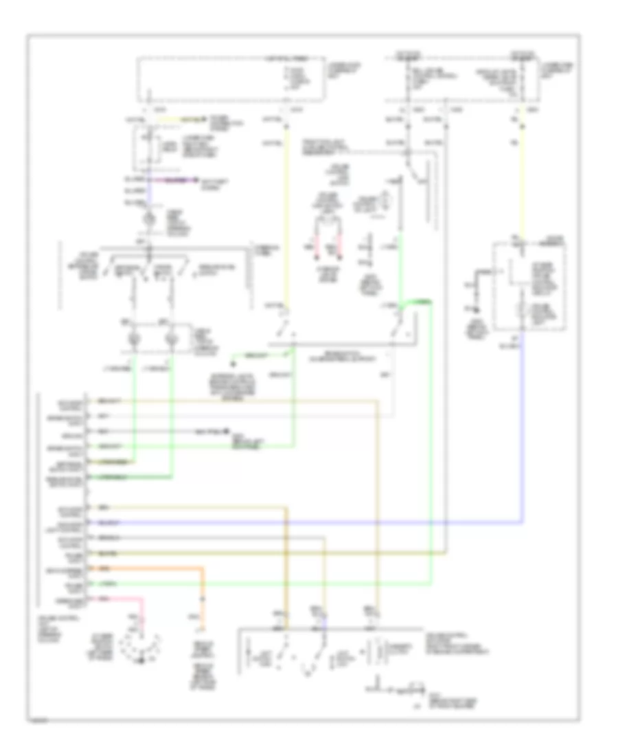
CRUISE CONTROL
Cruise Control Wiring Diagram for Acura 2.5TL 1998
 https://portal-diagnostov.com/license.html
Automotive Electricians Portal FZCO
Automotive Electricians Portal FZCO
https://portal-diagnostov.com/license.html
https://portal-diagnostov.com/license.html
Automotive Electricians Portal FZCO
Automotive Electricians Portal FZCOList of elements for Cruise Control Wiring Diagram for Acura 2.5TL 1998:
- A/t gear position switch (left rear of trans)
- A/t gear position/ cruise control indicator circuit
- Actuator control
- Anti-theft system
- Back-up lights, meter lights (sun roof) fuse 1 10a
- Brake switch (on brake pedal support)
- Brake switch input
- C12
- C216
- C219
- C406
- C603
- Cable reel (top of steering column)
- Cancel switch
- Cruise control actuator (right front corner of engine compartment)
- Cruise control indicator light
- Cruise control main switch
- Cruise control main switch light
- Cruise control on light
- Cruise control set/resume cancel switch
- Cruise control unit (left of steering column)
- Disengage input
- Ecu, cruise control, eat ecu fuse 4 20a
- Exterior lights, engine controls, transmission and anti-lock brakes systems
- Front fog light & cruise control main switch
- G101 (behind right side of front bumper)
- G200 (behind left kick panel)
- Gauge assembly
- Ground
- Horn relay
- Hot at all times
- Hot in on or start
- Indicator light control
- Interior lights system
- J/c
- Limit switch high
- Limit switch low
- Magnetic clutch
- Off
- Pnk
- Power distribution system
- Power input
- Red
- Resume/accel switch
- Resume/accel switch input
- Set/decel switch
- Set/decel switch input
- Steering wheel
- Stop horn fuse 30 20a
- Under-dash fuse/relay box
- Under-dash relay box (behind right side of dash)
- Under-hood fuse/relay box
- Vehicle speed input
- Vehicle speed output
- Vehicle speed sensor (left side of trans)
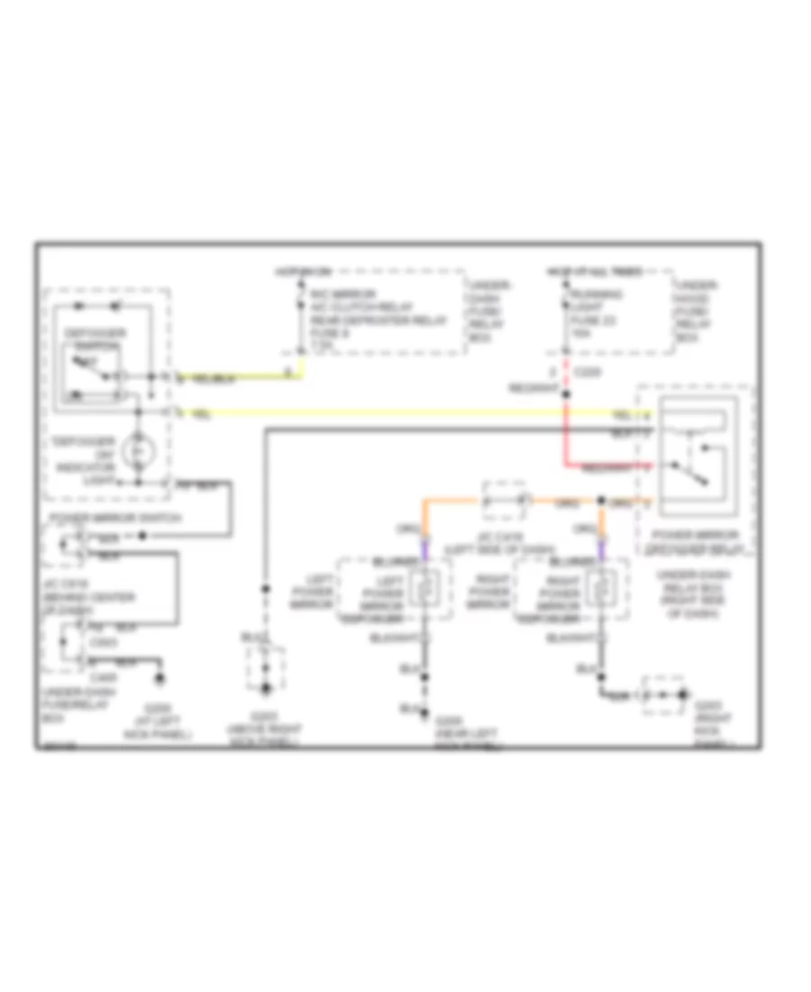
DEFOGGERS
Heated Mirrors Wiring Diagram for Acura 2.5TL 1998
 https://portal-diagnostov.com/license.html
Automotive Electricians Portal FZCO
Automotive Electricians Portal FZCO
https://portal-diagnostov.com/license.html
https://portal-diagnostov.com/license.html
Automotive Electricians Portal FZCO
Automotive Electricians Portal FZCOList of elements for Heated Mirrors Wiring Diagram for Acura 2.5TL 1998:
- "defogger on" indicator light
- C220
- C405
- C603
- Defogger switch
- G200 (at left kick panel)
- G200 (near left kick panel)
- G203 (above right kick panel)
- G203 (right kick panel)
- Hot at all times
- Hot in on
- J/c c419 (left side of dash)
- J/c c616 (behind center of dash)
- Left power mirror
- Left power mirror defogger
- Off
- Power mirror defogger relay
- Power mirror switch
- R/c mirror a/c clutch relay rear defroster relay fuse 8 7.5a
- Right power mirror
- Right power mirror defogger
- Running light fuse 23 10a
- Under- dash fuse/ relay box
- Under- hood fuse/ relay box
- Under-dash fuse/relay box
- Under-dash relay box (right side of dash)
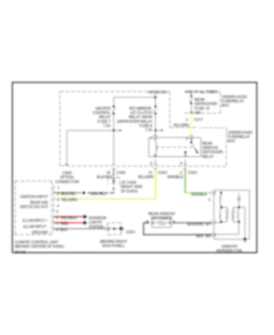
Rear Defogger Wiring Diagram for Acura 2.5TL 1998
 https://portal-diagnostov.com/license.html
Automotive Electricians Portal FZCO
Automotive Electricians Portal FZCO
https://portal-diagnostov.com/license.html
https://portal-diagnostov.com/license.html
Automotive Electricians Portal FZCO
Automotive Electricians Portal FZCOList of elements for Rear Defogger Wiring Diagram for Acura 2.5TL 1998:
- (behind right kick panel)
- C217
- C406
- C503
- C603
- C909 option connector
- Climate control unit (behind center of dash)
- G203
- Ground
- Heater control relay fuse 7 7.5a
- Hot at all times
- Hot in on
- Ignition input
- Illum input +
- Illum input -
- Interior lights system
- J/c c444 (right side of dash)
- R/c mirror, a/c clutch relay, rear defroster relay fuse 8 7.5a
- Rear defroster fuse 16 40a
- Rear win defog sw out
- Rear window defogger
- Rear window defogger relay
- Red
- Under-dash fuse/relay box
- Under-hood fuse/relay box
- Window antenna coil
ENGINE PERFORMANCE
2.5L
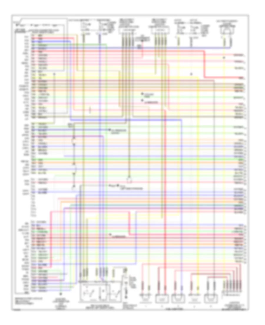
2.5L, Engine Performance Wiring Diagram (1 of 3) for Acura 2.5TL 1998
 https://portal-diagnostov.com/license.html
Automotive Electricians Portal FZCO
Automotive Electricians Portal FZCO
https://portal-diagnostov.com/license.html
https://portal-diagnostov.com/license.html
Automotive Electricians Portal FZCO
Automotive Electricians Portal FZCOList of elements for 2.5L, Engine Performance Wiring Diagram (1 of 3) for Acura 2.5TL 1998:
- (below right front footrest)
- (below right side of dash)
- (below right side of dash) junction connector (c436)
- (left side of
- (left side of engine)
- (on throttle body)
- (right side of dash)
- 10a
- 15a
- 2wbs
- 7.5a
- A/c compressor clutch relay
- A/c pressure switch
- A10
- A11
- A12
- A13
- A14
- A15
- A16
- A17
- A18
- A19
- A20
- A21
- A22
- A23
- A24
- A25
- A26
- Acc
- Acs
- Afsa
- Afsb
- Alt c
- Alt f
- Alternator
- At chk
- Atp pn
- B10
- B11
- B12
- B13
- B14
- B15
- B16
- Baro out
- Bk sw
- Box
- C10
- C11
- C12
- C216
- C402
- C406
- Ckf m
- Ckp m
- Ckp p
- Connector (c117)
- Connector (c444)
- Cooling fans
- Cyp m
- Cyp p
- D10
- D11
- D12
- D13
- D14
- D15
- D16
- D17
- D18
- D19
- D20
- D21
- D22
- E sol
- Ect
- Egrl
- Electric load detector unit (charging circuit)
- Engine compartment)
- Engine control module
- Fan c
- Fas
- Ffs
- Fks
- Flr
- Fuel injectors
- Fuel pump (in fuel tank)
- Fuse
- G112
- G112 (left side of engine)
- G401 (right front of trunk)
- Hot at all times
- Hot in on or start
- Hot in start
- Iab sol
- Iacv
- Iat
- Idle air control valve
- Igm
- Igp1
- Igp2
- Inj1
- Inj2
- Inj3
- Inj4
- Inj5
- Junction
- Junction
- Junction connector (c430)
- K-line
- Lg1
- Lg2
- Maf m
- Maf p
- Mcs
- Mil
- Pcs
- Pg1
- Pg2
- Pgm-fi main relay (behind left side of dash)
- Pho2s
- Pnk
- Po2shtc
- Psp sw
- Ptank
- Red
- Rks
- Scs
- Sg1
- Sg2
- Sho2s
- So2shtc
- Sts
- Tdc m
- Tdc p
- Tps
- Under- dash fuse/ relay box
- Under- hood fuse/ relay
- Vbu
- Vcc1
- Vcc2
- Vref
- Vss
- Vsv
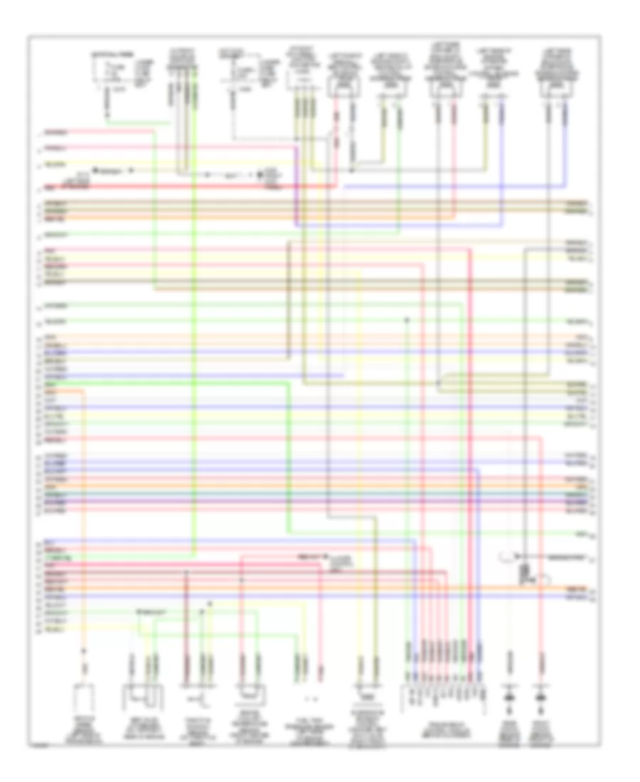
2.5L, Engine Performance Wiring Diagram (2 of 3) for Acura 2.5TL 1998
 https://portal-diagnostov.com/license.html
Automotive Electricians Portal FZCO
Automotive Electricians Portal FZCO
https://portal-diagnostov.com/license.html
https://portal-diagnostov.com/license.html
Automotive Electricians Portal FZCO
Automotive Electricians Portal FZCOList of elements for 2.5L, Engine Performance Wiring Diagram (2 of 3) for Acura 2.5TL 1998:
- (at right
- (c463)
- (in front console) data link connector
- (left rear corner of eng compt) evaporative emission bypass solenoid valve
- (left rear corner of eng compt) evaporative emission purge control solenoid valve
- (left rear of engine) intake air bypass control solenoid valve
- (left side of engine compt) engine mount control solenoid valve
- (left side of firewall) egr control solenoid valve
- 10a
- A10
- A20
- A24
- Afsa
- Afsb
- At chk
- Atp pn
- B19
- B20
- Baro s
- Braided wire
- C216
- C406
- Climate control unit
- Ect
- Egr valve lift sensor (on top right rear of engine
- Engine coolant temperature sensor (front center of engine)
- Evaporative emission control canister vent shut valve (right front of eng compt)
- Fas
- Ffs
- Front knock sensor (front of engine)
- Fuel tank pressure sensor (left rear of engine compartment)
- Fuse
- Fuse 4 20a
- G112 (left side of engine)
- G203 (right kick panel)
- Hot at all times
- Hot in on or start
- Junction connector
- Kick panel)
- Pnk
- Rear knock sensor (rear of engine)
- Red
- Throttle position sensor (on throttle body)
- Tps
- Transmission control module (behind glove box)
- Under- dash fuse/ relay box
- Under- hood fuse/ relay box
- Vehicle speed sensor (left side of transmission)
- Vref
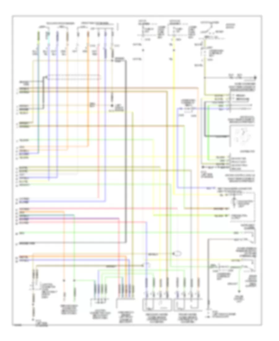
2.5L, Engine Performance Wiring Diagram (3 of 3) for Acura 2.5TL 1998
 https://portal-diagnostov.com/license.html
Automotive Electricians Portal FZCO
Automotive Electricians Portal FZCO
https://portal-diagnostov.com/license.html
https://portal-diagnostov.com/license.html
Automotive Electricians Portal FZCO
Automotive Electricians Portal FZCOList of elements for 2.5L, Engine Performance Wiring Diagram (3 of 3) for Acura 2.5TL 1998:
- (front right of engine)
- (left side of engine)
- (right rear corner of engine compartment)
- Acc
- Box
- Braided
- Braided wire
- Brake switch (on brake pedal support)
- C101
- C102
- C219
- C404
- C405
- C406
- C406 underdash fuse/relay box
- C603
- C907
- Ckf
- Ckp
- Coil wire
- Cruise control unit
- Cyp
- Distributor
- Fuse 1 10a
- Fuse 30 20a
- G100 (left front corner of eng compt)
- G112
- G112 (left side of engine)
- Ground
- Hot at all times
- Hot in on or start
- Ign input pow
- Ign input sig
- Ignition coil (right rear corner of engine compartment)
- Ignition control module
- Ignition switch
- Instrument cluster
- Junction connector (c436) (below right side of dash)
- Junction connector (c444) (below right side of dash)
- Lock
- Malfunction indicator light
- Mass airflow sensor (left front corner of eng compt)
- Noise condenser
- Park/neutral output
- Power steering pressure switch (on power steering line)
- Pri out cont
- Primary
- Primary heated oxygen sensor (upstream of 1st converter)
- Red
- Secondary
- Secondary heated oxygen sensor (upstream of 2nd converter)
- Service check connector (behind right side of dash)
- Start
- Tdc
- Tdc/ckp/cyp/ckf sensor
- Test tachometer connector (next to ignition coil)
- Under- dash fuse/ relay
- Under- hood fuse/ relay
- Under-dash fuse/relay
- Under-dash fuse/relay box
EXTERIOR LIGHTS
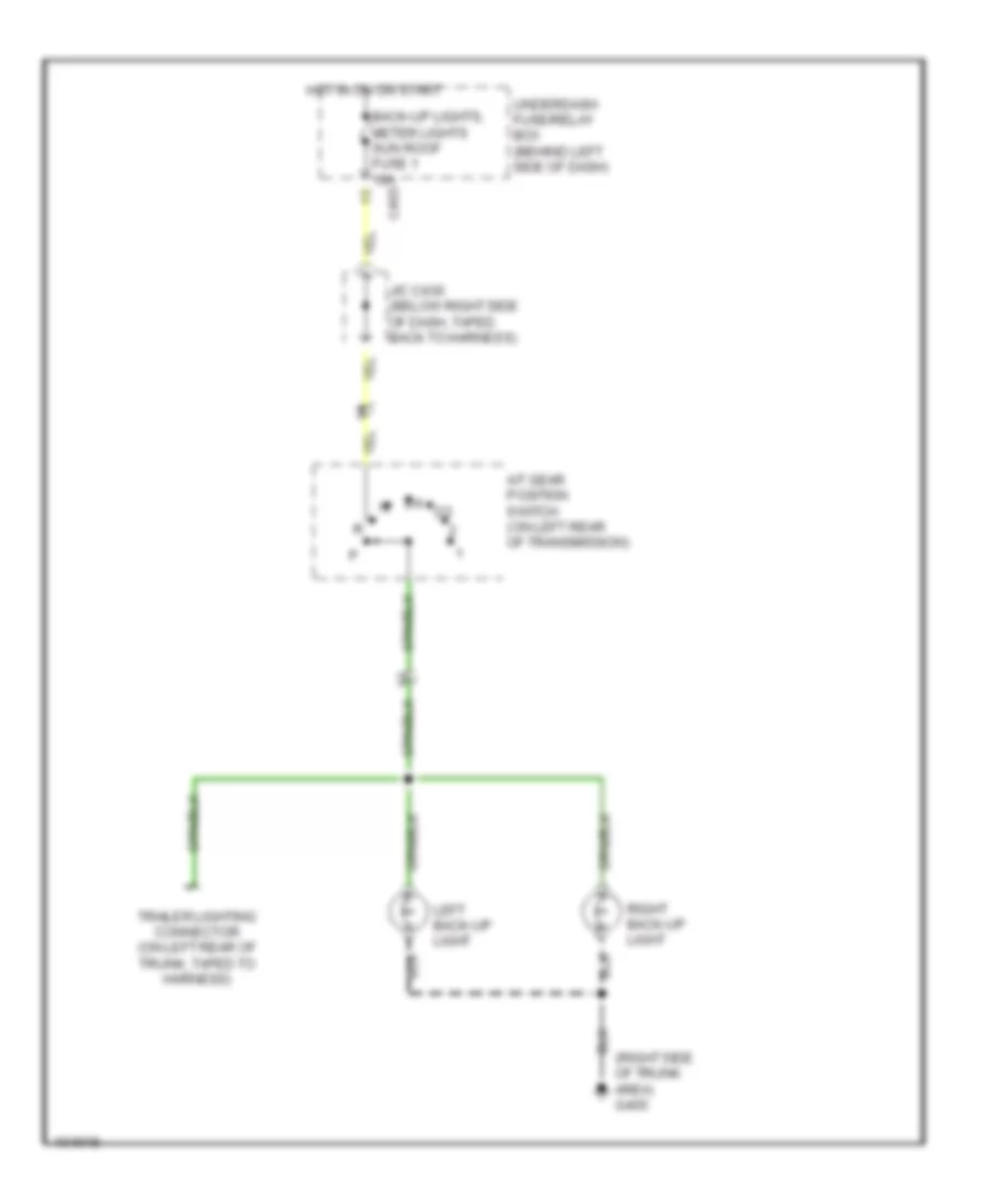
Back-up Lamps Wiring Diagram for Acura 2.5TL 1998
 https://portal-diagnostov.com/license.html
Automotive Electricians Portal FZCO
Automotive Electricians Portal FZCO
https://portal-diagnostov.com/license.html
https://portal-diagnostov.com/license.html
Automotive Electricians Portal FZCO
Automotive Electricians Portal FZCOList of elements for Back-up Lamps Wiring Diagram for Acura 2.5TL 1998:
- (right side of trunk area) g405
- A/t gear position switch (on left rear of transmission)
- Back-up lights, meter lights sun roof fuse 1 10a
- C405
- Hot in on or start
- J/c c430 (below right side of dash, taped back to harness)
- Left back-up light
- Right back-up light
- Trailer lighting connector (on left rear of trunk, taped to harness)
- Underdash fuse/relay box (behind left side of dash)
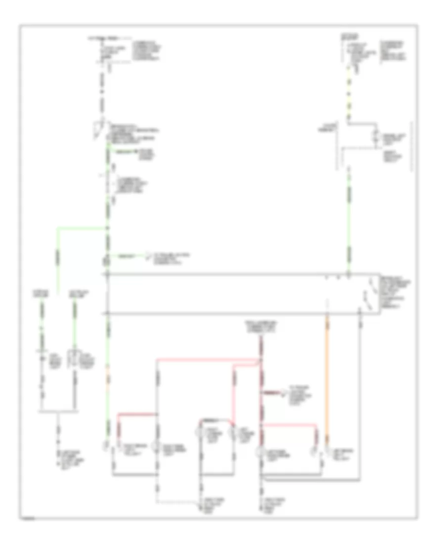
Exterior Lamps Wiring Diagram (1 of 3) for Acura 2.5TL 1998
 https://portal-diagnostov.com/license.html
Automotive Electricians Portal FZCO
Automotive Electricians Portal FZCO
https://portal-diagnostov.com/license.html
https://portal-diagnostov.com/license.html
Automotive Electricians Portal FZCO
Automotive Electricians Portal FZCOList of elements for Exterior Lamps Wiring Diagram (1 of 3) for Acura 2.5TL 1998:
- (behind left kick panel) g200
- C216
- C219
- C402
- C405
- C504
- Combination light switch
- G100 (left front corner of engine compartment)
- G101 (behind right side of front bumper)
- Head
- Head- light switch
- Hot at all times
- J/c c436 (below right side of dash, taped to harness)
- Left fog light
- Left front parking light
- Left front side marker light
- Off
- Park
- Right front parking light
- Right front side marker light
- Small light fuse 21 15a
- Taillight relay
- To brake lights/ taillights, rear side marker lights & licence plate lights (diagram 2 of 3)
- Underdash fuse/relay box (behind left side of dash)
- Underhood fuse/relay box (on right side of engine compartment)
Exterior Lamps Wiring Diagram (2 of 3) for Acura 2.5TL 1998
 https://portal-diagnostov.com/license.html
Automotive Electricians Portal FZCO
Automotive Electricians Portal FZCO
https://portal-diagnostov.com/license.html
https://portal-diagnostov.com/license.html
Automotive Electricians Portal FZCO
Automotive Electricians Portal FZCOList of elements for Exterior Lamps Wiring Diagram (2 of 3) for Acura 2.5TL 1998:
- "brake lamp" indicator light
- (left side of rear floor, near "b" pillar) g317
- (right side of trunk area) g405
- Back-up lights, meter lights, sun roof fuse 1 10a
- Brake switch (closed with brake pedal depressed) (behind dash, on brake pedal support)
- Brakelight failure sensor (on left rear of trunk, part of combination light assembly)
- C219
- C406
- C503
- C603
- Cruise control system
- From underdash fuse/relay box (diagram 1 of 3)
- Gauge assembly
- High mount brake light
- Hot at all times
- Hot in on or start
- Left brake light/ taillight
- Left license plate light
- Left rear side marker light
- Right brake light/ taillight
- Right license plate light
- Right rear side marker light
- Safety indicator circuit
- Stop, horn fuse 30 20a
- To trailer lighting connector (diagram 3 of 3)
- Underdash fuse/relay box (behind left side of dash)
- Underhood fuse/relay box (on right side of engine compartment)
- W/o trunk spoiler
- W/trunk spoiler
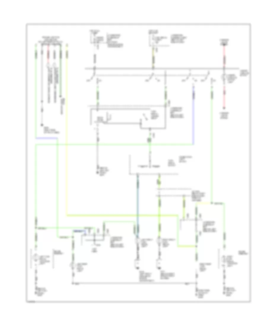
Exterior Lamps Wiring Diagram (3 of 3) for Acura 2.5TL 1998
 https://portal-diagnostov.com/license.html
Automotive Electricians Portal FZCO
Automotive Electricians Portal FZCO
https://portal-diagnostov.com/license.html
https://portal-diagnostov.com/license.html
Automotive Electricians Portal FZCO
Automotive Electricians Portal FZCOList of elements for Exterior Lamps Wiring Diagram (3 of 3) for Acura 2.5TL 1998:
- (behind left kick panel) g200
- (not used)
- (right side of trunk area) g405
- A14
- B from left rear side marker light (diagram 2 of 3)
- Back-up lights sytem
- C from brake light failure sensor (diagram 2 of 3)
- C216
- C405
- C406
- C504
- C603
- Combination light switch
- G100 (left front corner of engine compartment)
- G101 (behind right side of front bumper)
- G405 (right side of trunk area)
- Gauge assembly
- Hazard fuse 35 10a
- Hazard warning switch
- Hazard warning switch light
- Hot at all times
- Hot in on or start
- Interior lights system
- J/c c444 (below right side of dash, taped to harness)
- Left
- Left front turn signal light
- Left rear turn signal light
- Left turn signal indicator light
- Off
- Red
- Right
- Right front turn signal light
- Right rear turn signal light
- Right turn signal indicator light
- Solid state
- Trailer lighting connector (on left rear of trunk, taped to harness)
- Turn signal fuse 5 7.5a
- Turn signal switch
- Turn signal/ hazard relay
- Underdash fuse/relay box (behind left side of dash)
- Underhood fuse/relay box (on right side of engine compartment)
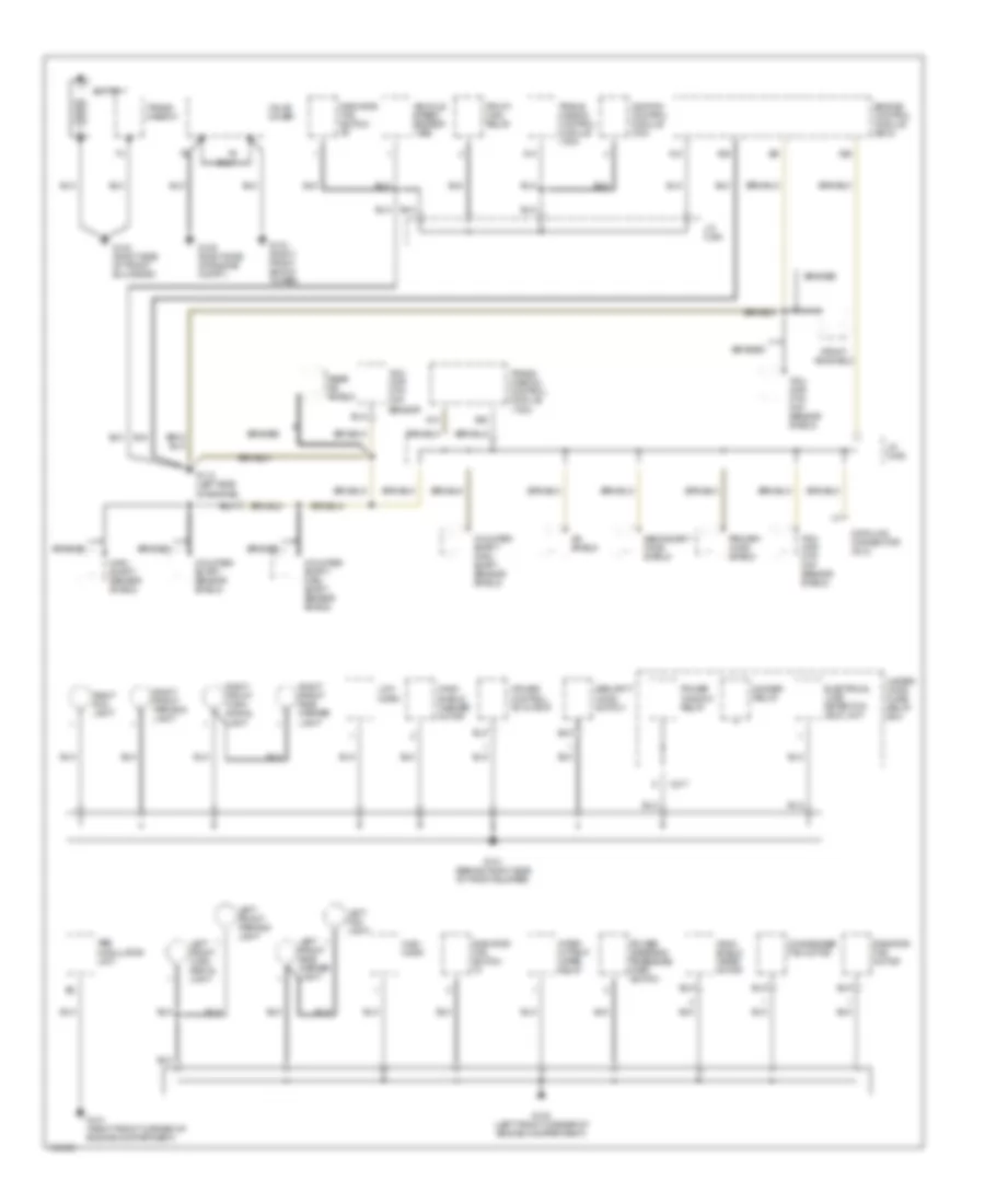
GROUND DISTRIBUTION
Ground Distribution Wiring Diagram (1 of 3) for Acura 2.5TL 1998
 https://portal-diagnostov.com/license.html
Automotive Electricians Portal FZCO
Automotive Electricians Portal FZCO
https://portal-diagnostov.com/license.html
https://portal-diagnostov.com/license.html
Automotive Electricians Portal FZCO
Automotive Electricians Portal FZCOList of elements for Ground Distribution Wiring Diagram (1 of 3) for Acura 2.5TL 1998:
- A12
- A13
- A14
- A25
- A26
- Abs modulator unit
- Battery
- Braided
- C217
- Condenser fan motor
- Counter- shaft/ main- shaft sensor shield
- Counter- shaft/ sensor shield
- Cruise control actuator
- Data link connector (dlc)
- Dimmer relay
- Electrical load detector (eld) unit
- Engine control module (ecm)
- Front ks shield
- G100 (left front corner of engine compartment)
- G101 (behind right side of front bumper)
- G101 (right front corner of engine compartment)
- G103 (right front shock tower)
- G105 (right side of engine compt.)
- G112 (left side of engine)
- G123 (right side of front bulkhead)
- High horn
- Ignition control module (icm)
- Inter- mittent wiper relay
- J/c c430
- J/c c436
- Ks shield
- Left fog light
- Left front parking light
- Left front side marker light
- Left front turn signal light
- Low horn
- Main- shaft/ sensor shield
- Pgm-fi main relay
- Power steering pressure (psp) switch
- Power window relay
- Primary ho2s shield
- Radiator fan motor
- Radiator fan switch "a"
- Radiator fan switch "b"
- Rear ks shield
- Right fog light
- Right front parking light
- Right front side marker light
- Right front turn signal light
- Secondary ho2s shield
- Security hood switch
- Tdc/ ckp/ cyp/ ckf sensor
- Tdc/ ckp/ cyp/ ckf sensor shield
- Trans- mission
- Trans- mission control module (tcm)
- Under- hood fuse/ relay box
- Valve cover
- Vehicle speed sensor (vss)
- Wind- shield washer motor
- Wind- shield wiper motor
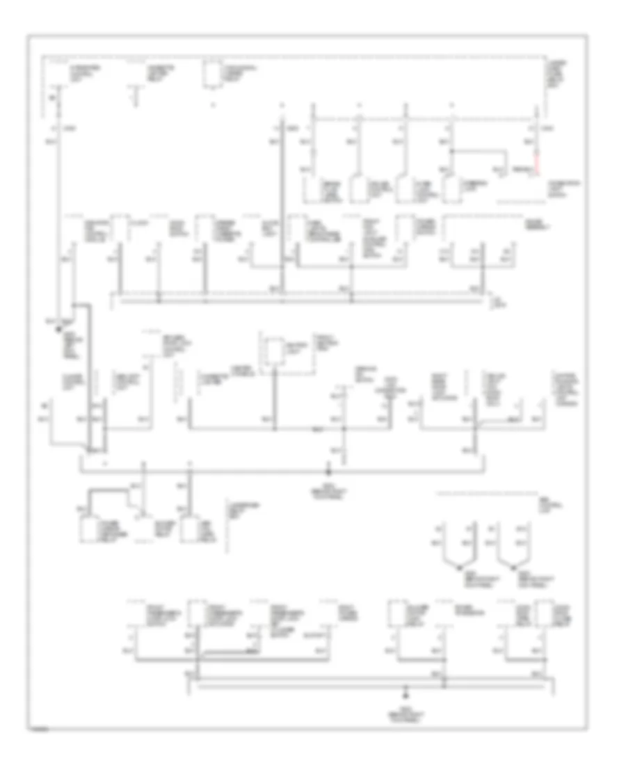
Ground Distribution Wiring Diagram (2 of 3) for Acura 2.5TL 1998
 https://portal-diagnostov.com/license.html
Automotive Electricians Portal FZCO
Automotive Electricians Portal FZCO
https://portal-diagnostov.com/license.html
https://portal-diagnostov.com/license.html
Automotive Electricians Portal FZCO
Automotive Electricians Portal FZCOList of elements for Ground Distribution Wiring Diagram (2 of 3) for Acura 2.5TL 1998:
- A13
- A14
- Abs control unit
- Abs fail- safe relay
- Ashtray light
- B12
- Blower motor high relay
- Blower motor relay
- Brake fluid level switch
- C12
- C402
- C405
- C603
- Ceiling light (w/o moon- roof only)
- Center console
- Cigarette lighter
- Cigarette lighter relay
- Climate control unit
- Clock
- Combination light switch
- Cruise control unit
- Dash lights brightness controller
- Data link connector (dlc)
- Daytime running lights control unit (canada)
- Front ashtray tray
- Front fog light & cruise control main switch
- Front passenger's door lock actuator
- Front passenger's door lock key cylinder switch
- Front passenger's door lock switch
- G200 (behind left kick panel)
- G203 (behind right kick panel)
- Gauge assembly
- Glove box light
- Integrated control unit
- Inter- lock control unit
- J/c c616
- Keyless door lock control unit
- Moon- roof close relay
- Moon- roof open relay
- Moon- roof switch
- Parking pin switch
- Power mirror defogger relay
- Power mirror switch
- Power transistor
- Radiator fan control module
- Right power mirror
- Right rear door lock actuator
- Security control unit
- Steering lock
- Stereo radio/ cassette player
- Turn signal/ hazard relay
- Under- dash fuse/ relay box
- Underdash relay box
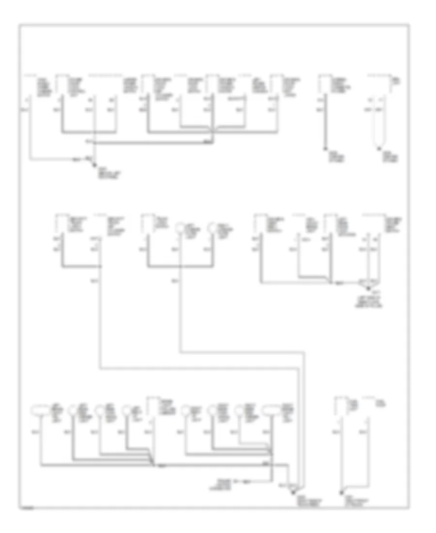
Ground Distribution Wiring Diagram (3 of 3) for Acura 2.5TL 1998
 https://portal-diagnostov.com/license.html
Automotive Electricians Portal FZCO
Automotive Electricians Portal FZCO
https://portal-diagnostov.com/license.html
https://portal-diagnostov.com/license.html
Automotive Electricians Portal FZCO
Automotive Electricians Portal FZCOList of elements for Ground Distribution Wiring Diagram (3 of 3) for Acura 2.5TL 1998:
- (left side of rear floor, near "b" pillar)
- A14
- Brake light failure sensor
- C514
- Driver's door lock act- uator
- Driver's door lock key cylinder switch
- Driver's door lock switch
- Driver's power seat switch
- Driver's power window motor
- Driver's seat belt switch
- Fuel pump
- Fuel tank unit
- G200 (behind left kick panel)
- G206 (center of dash)
- G317
- G401 (right front of trunk)
- G405 (right side of trunk area)
- High mount brake light
- Left back- up light
- Left brake light/ tail- light
- Left license plate light
- Left power mirror (canada)
- Left rear door lock actuator
- Left rear side marker light
- Left rear turn signal light
- Master power window switch
- Power door lock control unit
- Right back- up light
- Right brake light/ tail- light
- Right license plate light
- Right rear side marker light
- Right rear turn signal light
- Security trunk key cylinder switch
- Security trunk latch switch
- Srs unit
- Stereo radio/ cassette player
- Trailer lighting connector
- Trunk latch switch
- Wind- shield wiper/ washer switch
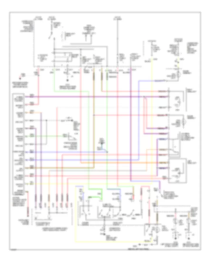
HEADLIGHTS
Headlamps & Fog Lamps Wiring Diagram, with DRL for Acura 2.5TL 1998
 https://portal-diagnostov.com/license.html
Automotive Electricians Portal FZCO
Automotive Electricians Portal FZCO
https://portal-diagnostov.com/license.html
https://portal-diagnostov.com/license.html
Automotive Electricians Portal FZCO
Automotive Electricians Portal FZCOList of elements for Headlamps & Fog Lamps Wiring Diagram, with DRL for Acura 2.5TL 1998:
- (behind left kick panel)
- (behind right side of front bumper)
- (left front corner of eng. compt.)
- (not used)
- Anti- theft system
- Back-up & meter lights (sun roof) fuse 1 10a
- Battery fuse 15 100a
- Battery input
- Brake indicator control
- C216
- C217
- C218
- C219
- C220
- C406
- C603
- Combination light switch
- Day lights fuse 10 7.5a
- Daytime running lights control unit (behind right side of dash)
- Defogger system (power mirror defogger relay)
- Dimmer relay
- Dimmer relay input
- Dimmer switch
- Drl indicator light
- Drl indicator light control
- Drl output
- Flash-to- pass switch
- Fog light switch
- From under-hood fuse/relay box (diagram 1 of 1)
- Front fog light fuse 36 15a
- Front fog light relay (in under-dash relay box)
- G100
- G101
- G101 (behind right side of front bumper)
- G200
- G200 (behind left kick panel)
- G203 (behind right kick panel)
- Gauge assembly
- Ground
- Head
- Headlight relay
- Headlight switch
- Headlights on input
- Hi beam drl mode control
- High
- High beam indicator light
- Hot at all times
- Hot in on
- Hot in on or start
- Ignition input
- Instrument cluster system
- J/c
- J/c c430 (below right side of dash)
- Left fog light
- Left headlight
- Left headlight fuse 19 15a
- Low
- Low beam cut relay (in under-dash relay box)
- Off
- On ind
- Park
- Parking brake input
- Parking brake switch (below center console)
- Red
- Right fog light
- Right headlight
- Right headlight fuse 20 15a
- Running light fuse 23 15a
- Small light fuse 21 15a
- To dimmer relay (diagram 1 of 1)
- Under-dash fuse/relay box (behind right side of dash)
- Under-hood fuse/relay box (right side of eng. compt.)
- Under-hood fuse/relay box (right side of engine compartment)
Headlamps & Fog Lamps Wiring Diagram, without DRL for Acura 2.5TL 1998
 https://portal-diagnostov.com/license.html
Automotive Electricians Portal FZCO
Automotive Electricians Portal FZCO
https://portal-diagnostov.com/license.html
https://portal-diagnostov.com/license.html
Automotive Electricians Portal FZCO
Automotive Electricians Portal FZCOList of elements for Headlamps & Fog Lamps Wiring Diagram, without DRL for Acura 2.5TL 1998:
- (not used)
- (right side of eng. compt.)
- Anti-theft system
- Battery fuse 15 100a
- C216
- C217
- C218
- C219
- Combination light switch
- Dimmer relay
- Dimmer switch
- Flash-to-pass switch
- Fog light switch
- From a
- Front fog light fuse 36 15a
- Front fog light relay
- G100 (left front corner of eng. compt.)
- G101 (behind right side of front bumper)
- G200 (behind left kick panel)
- Gauge assembly
- Head
- Headlight relay
- Headlight switch
- High
- High beam indicator light
- Hot at all times
- J/c
- J/c c430 (below right side of dash)
- L. headlight fuse 19 15a
- Left fog light
- Left headlight
- Low
- Off
- On ind.
- Park
- R. headlight fuse 20 15a
- Red
- Right fog light
- Right headlight
- Small light fuse 21 15a
- To dimmer relay (diagram 1 of 1)
- Under-dash relay box (behind right side of dash)
- Under-hood fuse/relay b box (diagram 1 of 1)
- Under-hood fuse/relay box
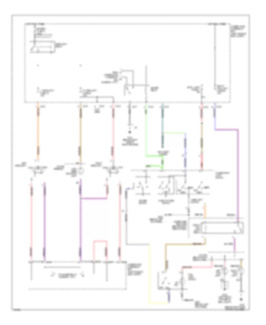
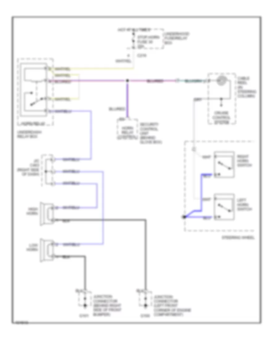
HORN
Horn Wiring Diagram for Acura 2.5TL 1998
 https://portal-diagnostov.com/license.html
Automotive Electricians Portal FZCO
Automotive Electricians Portal FZCO
https://portal-diagnostov.com/license.html
https://portal-diagnostov.com/license.html
Automotive Electricians Portal FZCO
Automotive Electricians Portal FZCOList of elements for Horn Wiring Diagram for Acura 2.5TL 1998:
- C216
- Cable reel (in steering column)
- Cruise control system
- G100
- G101
- High horn
- Horn relay
- Horn relay control
- Hot at all times
- J/c c463 (right side of dash)
- Junction connector (behind right side of front bumper)
- Junction connector (left front corner of engine compartment)
- Left horn switch
- Low horn
- Right horn switch
- Security control unit (behind glove box)
- Steering wheel
- Stop,horn fuse 30 20a
- Underdash relay box
- Underhood fuse/relay box
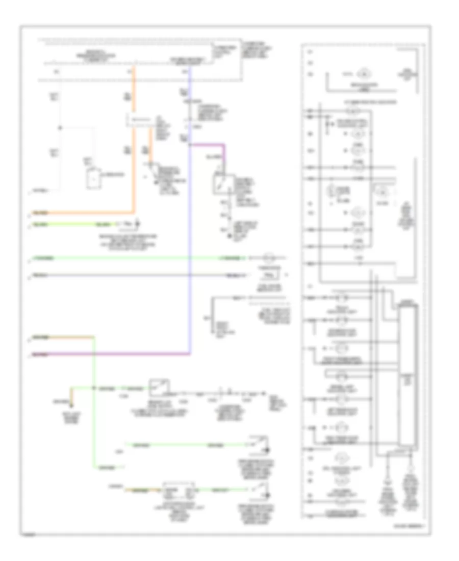
INSTRUMENT CLUSTER
Instrument Cluster Wiring Diagram (1 of 2) for Acura 2.5TL 1998
 https://portal-diagnostov.com/license.html
Automotive Electricians Portal FZCO
Automotive Electricians Portal FZCO
https://portal-diagnostov.com/license.html
https://portal-diagnostov.com/license.html
Automotive Electricians Portal FZCO
Automotive Electricians Portal FZCOList of elements for Instrument Cluster Wiring Diagram (1 of 2) for Acura 2.5TL 1998:
- (behind left kick panel) g200
- (not used)
- (not used) (right kick panel) c455
- A/t gear position switch (on left rear of transmission)
- A10
- A11
- A12
- A13
- A14
- A15
- A16
- A17
- Abs indicator light
- Air conditioning system
- Anti-lock brakes system
- B10
- B11
- B12
- B14
- B15
- B16
- Back-up lights meter lights sun roof fuse 1 10a
- Brake light failure sensor (on left rear of trunk, part of combination light assembly)
- Brake system indicator light
- Bulb check ckt
- C10
- C12
- C13
- C405
- C603
- Canada
- Cruise control system
- Drive ckt
- Drive input
- Ecu cruise control eat ecu fuse 4 20a
- Engine controls system
- Engine coolant temperature gauge
- Engine speed
- Engine speed output
- Exterior lights system
- Fuel gauge
- Gauge assembly
- Head- lights system
- Headlights system
- Hot in on or start
- Hot in start
- Ignition coil (on right rear corner of engine compartment)
- Ind ctrl
- Interior lights system
- J/c c463 (at right kick panel, taped back to harness)
- J/c c616 (behind middle of dash)
- Left turn signal indicator light
- Low engine oil pressure indicator light
- Low fuel indicator light
- Malfunction indicator light (mil)
- Odometer/ tripmeter stepper motor
- P/n input
- Red
- Reverse input
- Right turn signal indicator light
- Seat belt reminder indicator light
- Shift inter- lock system
- Speedometer
- Starter signal fuse 9 7.5a
- Tach drive ckt
- Tachometer
- Test tachometer connector (next to ignition coil)
- To safety indi- cator (diagram 2 of 2)
- To safety indicator (diagram 2 of 2)
- Transmission control module (tcm) (behind glove box, behind keyless door lock control unit)
- Underdash fuse/relay box (behind left side of dash)
- Underdash fuse/ relay box (behind left side of dash)
- Underdash fuse/relay box (behind left side of dash)
- Usa
- Vehicle speed sensor (vss) (on left side of trans)
- Vss input
- Vss output
Instrument Cluster Wiring Diagram (2 of 2) for Acura 2.5TL 1998
 https://portal-diagnostov.com/license.html
Automotive Electricians Portal FZCO
Automotive Electricians Portal FZCO
https://portal-diagnostov.com/license.html
https://portal-diagnostov.com/license.html
Automotive Electricians Portal FZCO
Automotive Electricians Portal FZCOList of elements for Instrument Cluster Wiring Diagram (2 of 2) for Acura 2.5TL 1998:
- "brake lamp" indicator light
- (left side of rear floor, near "b" pillar) g317
- (right front of trunk) g401
- 1 ind
- 2 ind
- A/t gear posi- tion/ cruise control ckt
- A/t gear position indicator
- A11
- A12
- A13
- A14
- A15
- Alternator
- Anti-lock brakes system
- B10
- B11
- B14
- B15
- B16
- Brake fluid level switch (closed with low fluid level) (in brake fluid reservoir)
- Brake ind. out.
- C324
- C325
- C402
- C405
- C406
- C603
- Canada
- Charging system indicator light
- Cruise control indicator light
- D3 ind
- D4 ind
- Daytime running lights (drl) control unit (behind right side of dash)
- Driver's door indicator light
- Driver's seat belt switch (closed with seat belt unbuckled)
- Driver's seat belt switch input
- Drl indicator light (canada)
- Engine coolant temperature (ect) sending unit (on center front of engine, on coolant outlet)
- Engine oil pressure indicator flasher ckt
- Engine oil pressure switch (opens above 4.3 psi) (next to oil filter)
- From brake system indicator light (diagram 1 of 2)
- From engine coolant temper- ature (ect) gauge (diagram 1 of 2)
- Front passenger's door indicator light
- Fuel gauge sending unit
- Fuel tank unit (below front of trunk, through access hole)
- G200 (behind left kick panel)
- Gauge assembly
- Gauge lights (7 bulbs)
- High beam indicator light
- Integrated control unit
- J/c c444 (below right side of dash)
- Left rear door indicator light
- N ind
- P ind
- P.b.
- R ind
- Right rear door indicator light
- Safety ind ckt
- Safety indicator
- Srs indicator ckt
- Srs indicator light
- Sw. in.
- Thermistor
- Trunk indicator light
- Underdash fuse/relay box (behind left side of dash)
- Usa
INTERIOR LIGHTS
Courtesy Lamps Wiring Diagram for Acura 2.5TL 1998
 https://portal-diagnostov.com/license.html
Automotive Electricians Portal FZCO
Automotive Electricians Portal FZCO
https://portal-diagnostov.com/license.html
https://portal-diagnostov.com/license.html
Automotive Electricians Portal FZCO
Automotive Electricians Portal FZCOList of elements for Courtesy Lamps Wiring Diagram for Acura 2.5TL 1998:
- (right side of trunk area) g405
- (w/ moonroof)
- Anti- theft system
- Anti-theft system
- B16
- C216
- C406
- C504
- C603
- Ceiling light
- Door
- Door locks system
- Door open input
- Door open output
- Driver's door courtesy light
- Driver's door switch
- Front passenger's door courtesy light
- Front passenger's door switch
- G203 (behind right kick panel)
- Gauge assembly
- Hot at all times
- In-line diode "a" (above underdash fuse/relay box, taped to harness)
- In-line diode "b" (behind right kick panel, taped to harness)
- Interior light fuse 37 15a
- J/c
- J/c c436 (below right side of dash, taped to harness)
- J/c c463 (behind right kick panel, taped to harness)
- Left rear door courtesy light
- Left rear door switch
- Off
- Red
- Right rear door courtesy light
- Right rear door switch
- Safety indicator
- Spotlight
- Trunk latch switch (closed w/trunk open)
- Trunk light
- Underdash fuse/relay box (behind left side of dash)
- Underdash fuse/relay box (behind left side of dash) c504
- Underhood fuse/relay box (on right side of engine compartment)
- W/ moonroof
- W/o moonroof
Entry Light Timer Wiring Diagram for Acura 2.5TL 1998
 https://portal-diagnostov.com/license.html
Automotive Electricians Portal FZCO
Automotive Electricians Portal FZCO
https://portal-diagnostov.com/license.html
https://portal-diagnostov.com/license.html
Automotive Electricians Portal FZCO
Automotive Electricians Portal FZCOList of elements for Entry Light Timer Wiring Diagram for Acura 2.5TL 1998:
- (behind left kick panel) g200
- A11
- B12
- Battery input
- C216
- C219
- C405
- C406
- C504
- Door switch
- Driver's door switch (closed with door open)
- Entry light timer circuit
- Ground
- Hot at all times
- Ignition key
- Ignition key light
- Input
- Integrated control unit
- Interior light fuse 37 15a
- Light control
- Steering lock
- Stop, horn fuse 30 20a
- Underdash fuse/relay box (behind left side of dash)
- Underhood fuse/relay box (on right side of engine compartment)
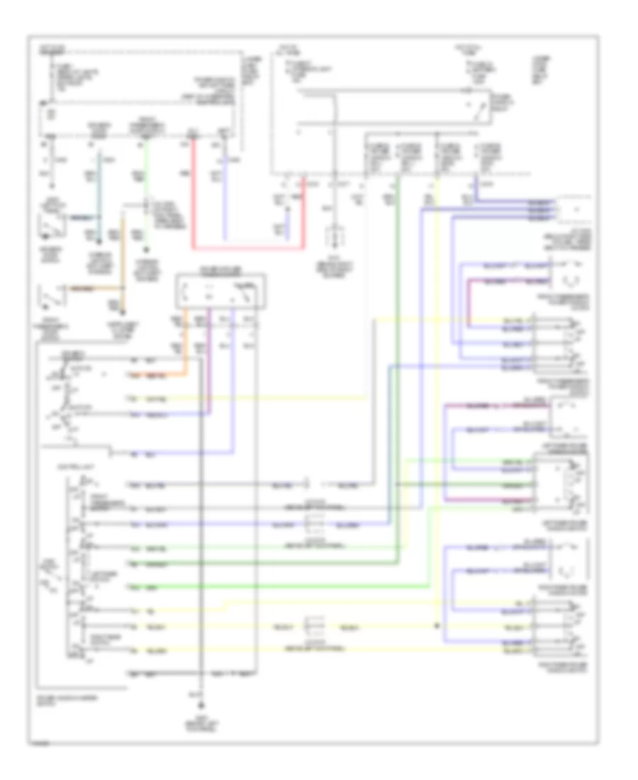
Instrument Illumination Wiring Diagram for Acura 2.5TL 1998
 https://portal-diagnostov.com/license.html
Automotive Electricians Portal FZCO
Automotive Electricians Portal FZCO
https://portal-diagnostov.com/license.html
https://portal-diagnostov.com/license.html
Automotive Electricians Portal FZCO
Automotive Electricians Portal FZCOList of elements for Instrument Illumination Wiring Diagram for Acura 2.5TL 1998:
- (behind left kick panel) g200
- A/t gear position console light
- A/t gear position/ cruise control indicator circuit
- A15
- Ash- tray light
- Bright
- C216
- C219
- C405
- Center console
- Cigarette lighter light
- Climate control unit
- Clock
- Combination light switch
- Dash lights brightness controller
- Dim
- Driver's vanity mirror light (closed w/cover opened)
- Fog light & cruise control main switch
- Front ashtray
- Front passenger's vanity mirror light (closed w/cover opened)
- G203 (behind right kick panel)
- Gauge assembly
- Gauge lights (7 bulbs)
- Glove box light
- Hazard warning switch
- Head
- Headlight switch
- Hot at all times
- J/c
- J/c c436 (below right side of dash, taped to harness)
- J/c c616 (behind center of dash)
- Moon- roof switch
- Off
- Park
- Power distribution system
- Power mirror switch
- Red
- Red/
- Small light fuse 21 15a
- Solid state
- Stereo radio/ cassette player
- Taillight relay
- Underdash fuse/relay box (behind left side of dash) c603
- Underhood fuse/relay box (on right side of engine compartment)
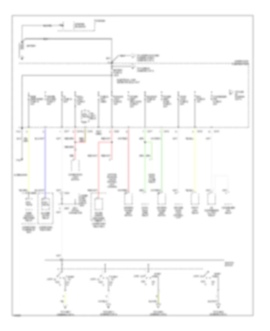
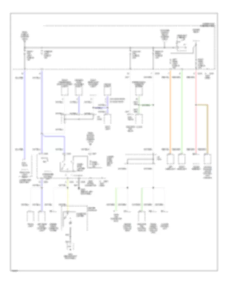
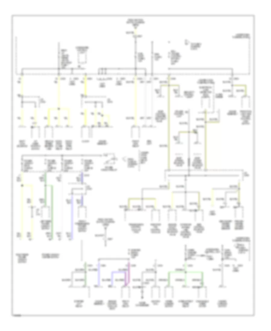
POWER DISTRIBUTION
Power Distribution Wiring Diagram (1 of 4) for Acura 2.5TL 1998
 https://portal-diagnostov.com/license.html
Automotive Electricians Portal FZCO
Automotive Electricians Portal FZCO
https://portal-diagnostov.com/license.html
https://portal-diagnostov.com/license.html
Automotive Electricians Portal FZCO
Automotive Electricians Portal FZCOList of elements for Power Distribution Wiring Diagram (1 of 4) for Acura 2.5TL 1998:
- (0)
- (i)
- (not used)
- A/c compressor clutch relay
- Acc
- Alternator
- Battery
- Battery fuse 15 100a
- Blower motor relay
- C216
- C217
- C218
- C219
- C220
- C403
- C907
- C911 option connector
- Coil
- Combination light switch
- Con- tacts
- Condenser fan fuse 34 20a
- Condenser fan relay
- Daytime running lights control unit (canada)
- Door lock fuse 32 20a
- Driver's power seat switch
- Ecu fuse 33 15a
- Electrical load detector (eld) unit
- Fuse 22 (not used)
- Heater blower fuse 17 30a
- Ig fuse 18 50a
- Ignition switch
- Keyless door lock control unit
- Lock
- Moon- roof close relay
- Moon- roof open relay
- On (ii)
- Pgm-fi main relay
- Power mirror defogger relay
- Power seat reclining fuse 27 20a
- Power seat slide fuse 31 20a
- Rear defroster fuse 16 40a
- Rear window defogger relay
- Red
- Running light fuse 23 15a
- Small light fuse 21 15a
- Start (iii)
- Starter
- Starter solenoid
- Sunroof fuse 29 30a
- T101
- T102
- Tail- light relay
- To fuse (diagram 3 of 4)
- To fuse 1 (diagram 4 of 4)
- To fuse 11 (diagram 3 of 4)
- To fuse 2 (diagram 4 of 4)
- To fuse 7 (diagram 2 of 4)
- To fuses 30 (diagram 2 of 4)
- To under-hood abs fuse/relay box (diagram 2 of 4)
- Under- dash fuse/ relay box
- Under-dash fuse/relay box
- Under-dash relay box
- Under-hood fuse/relay box
Power Distribution Wiring Diagram (2 of 4) for Acura 2.5TL 1998
 https://portal-diagnostov.com/license.html
Automotive Electricians Portal FZCO
Automotive Electricians Portal FZCO
https://portal-diagnostov.com/license.html
https://portal-diagnostov.com/license.html
Automotive Electricians Portal FZCO
Automotive Electricians Portal FZCOList of elements for Power Distribution Wiring Diagram (2 of 4) for Acura 2.5TL 1998:
- (not used)
- A/c compressor clutch relay
- A17
- Abs motor fuse 45 30a
- Abs b1 fuse 46 20a
- Abs control unit
- Abs fail-safe relay
- Abs pump motor
- Abs pump motor relay
- Abs unit fuse 48 10a
- B11
- Blower motor high relay
- Blower motor relay
- Brake switch
- C208
- C209
- C216
- C219
- C405
- C406
- C504
- C603
- C907
- C909 option connector
- Climate control unit
- Day lights fuse 10 7.5a
- Daytime running lights control unit (canada)
- From b battery (diagram 1 of 4)
- From battery (diagram 1 of 4)
- From ignition switch (diagram 1 of 4)
- Hazard fuse 35 10a
- Hazard warning switch
- Heater control relay fuse 7 7.5a
- Heater valve control solenoid valve
- Horn relay
- J/c c444
- J/c c463
- Mode control motor
- Power mirror switch
- R/c mirror, a/c clutch relay, rear defogger relay fuse 8 7.5a
- Radiator fan control module
- Rear window defogger relay
- Recircu- lation control motor
- Security control unit
- Security indicator
- Steering lock
- Stop, horn fuse 30 20a
- Under- dash fuse/ relay box
- Under- hood abs fuse/ relay box
- Under- hood fuse/ relay box
- Under-dash relay box
Power Distribution Wiring Diagram (3 of 4) for Acura 2.5TL 1998
 https://portal-diagnostov.com/license.html
Automotive Electricians Portal FZCO
Automotive Electricians Portal FZCO
https://portal-diagnostov.com/license.html
https://portal-diagnostov.com/license.html
Automotive Electricians Portal FZCO
Automotive Electricians Portal FZCOList of elements for Power Distribution Wiring Diagram (3 of 4) for Acura 2.5TL 1998:
- (not used)
- (w/ moon roof)
- (w/o moon roof)
- A23
- B12
- Back-up radio fuse 39 10a
- C216
- C218
- C219
- C403
- C404
- C405
- C406
- C504
- C603
- C907
- C908 option connector
- Ceiling light
- Center console
- Cigar- ette lighter relay
- Cigarette lighter
- Climate control unit
- Clock
- Con- tacts
- Cooling fan fuse 38 20a
- Data link connector (dlc)
- Daytime running lights control unit (canada)
- Dimmer relay
- Driver's door courtesy light
- Engine control module (ecm)
- From fuse 34 (diagram 1 of 4)
- From ignition switch (diagram 1 of 4)
- Front fog light fuse 36 15a
- Front fog light relay
- Front passenger's door courtesy light
- G200 (behind left kick panel)
- G203 (behind right kick panel)
- Gauge assembly
- Headlight relay
- Integrated control unit
- Interior light fuse 37 15a
- J/c c436
- J/c c444
- Left head- light fuse 19 15a
- Left headlight
- Left rear door courtesy light
- Radiator fan control module
- Radiator fan relay
- Radio fuse 11 10a
- Right head- light fuse 20 15a
- Right headlight
- Right rear door courtesy light
- Spot light
- Stereo radio/ cassette player
- To power window relay (diagram 4 of 4)
- Trans- mission control module (tcm)
- Trunk light
- Under- dash fuse/ relay box
- Under-dash relay box
- Under-hood fuse/relay box
Power Distribution Wiring Diagram (4 of 4) for Acura 2.5TL 1998
 https://portal-diagnostov.com/license.html
Automotive Electricians Portal FZCO
Automotive Electricians Portal FZCO
https://portal-diagnostov.com/license.html
https://portal-diagnostov.com/license.html
Automotive Electricians Portal FZCO
Automotive Electricians Portal FZCOList of elements for Power Distribution Wiring Diagram (4 of 4) for Acura 2.5TL 1998:
- (not used)
- A/t gear position switch
- A12
- A16
- A25
- Alter- nator
- B11
- Back- up lights, meter lights, sun roof fuse 1 10a
- C216
- C223
- C402
- C404
- C405
- C406
- C504
- C603
- C801
- C907
- Clock
- Cruise control unit
- Ecu cruise control eat ecu fuse 4 20a
- Egr control solenoid valve
- Electrical load detector (eld) unit
- Engine control module (ecm)
- Engine mount control solenoid valve
- Evap bypass solenoid valve
- Evap control canister vent shut
- Evap purge control solenoid valve
- From fuse 39 (diagram 3 of 4)
- From fuse 4 (diagram 4 of 4)
- From ignition switch (diagram 1 of 4)
- Front fog light and cruise control main switch
- Front passenger's power window switch
- Fuel pump fuse 2 15a
- Gauge assembly
- Hazard warning switch
- Ignition coil
- Intake air bypass (iab) control solenoid valve
- Integrated control unit
- Intermittent wiper relay
- J/c c-
- J/c c430
- J/c c463
- J/c c616
- Left rear power window switch
- Moon- roof close relay
- Moon- roof open relay
- Noise condenser
- Not used
- Pgm-fi main relay
- Power window fr-l fuse 28 20a
- Power window fr-r fuse 26 20a
- Power window master switch
- Power window relay
- Power window rr-l fuse 25 20a
- Power window rr-r fuse 24 20a
- Primary heated oxygen sensor
- Radiator fan control module
- Right rear power window switch
- Secondary heated oxygen sensor
- Security control unit
- Shift lock solenoid
- Srs fuse 3 10a
- Srs unit
- Starter cut relay
- Starter signal fuse 9 7.5a
- To fuse 5 (diagram 4 of 4)
- Transmission control module (tcm)
- Turn signal fuse 5 7.5a
- Under- hood fuse/ relay box
- Under-dash fuse/relay box
- Under-hood fuse/relay box
- Valve
- Vehicle speed sensor (vss)
- Windshield wiper motor
- Wiper washer fuse 6 30a
- Wiper/ washer switch
POWER DOOR LOCKS
Power Door Locks Wiring Diagram for Acura 2.5TL 1998
 https://portal-diagnostov.com/license.html
Automotive Electricians Portal FZCO
Automotive Electricians Portal FZCO
https://portal-diagnostov.com/license.html
https://portal-diagnostov.com/license.html
Automotive Electricians Portal FZCO
Automotive Electricians Portal FZCOList of elements for Power Door Locks Wiring Diagram for Acura 2.5TL 1998:
- (behind left kick panel) g200
- (behind right kick panel)
- Actuator ctrl
- Anti-theft & interior lights systems
- Anti-theft & warning systems
- Anti-theft system
- B16
- Battery
- C216
- C402
- C405
- C504
- C603
- Door lock actuator
- Door open input
- Door open output
- Dr unlock in
- Driver's door lock actuator
- Driver's door lock key cylinder switch
- Driver's door lock switch
- Driver's door switch
- Front passenger's door lock actuator
- Front passenger's door lock key cylinder switch
- Front passenger's door lock switch
- Front passenger's door switch
- Fuse 32 (door lock) 20a
- G203
- Gauge assembly
- Ground
- Hot at all times
- Ig key sw input
- Ignition key switch
- In-line diode 1 (behind right kick panel)
- In-line diode 2 (behind right kick panel)
- In-line diode 3 (above right kick panel)
- In-line diode 4 (behind glove box)
- Input
- Interior lights system
- J/c c419 (above left kick panel)
- J/c c430 (below right side of dash, taped to harness)
- Keyless door lock control unit (behind glove box)
- Kick panel) g200
- Knob switch
- Left rear door lock actuator
- Left rear door switch
- Lock
- Lock input
- Lock out
- Red
- Right rear door lock actuator
- Right rear door switch
- Safety indicator
- Security control unit (behind glove box, behind keyless door lock control unit)
- Security set a13
- Security set input
- Security set out
- Security unset a7
- Steering lock
- Un- lock
- Underdash fuse/relay box (behind left side of dash)
- Underhood fuse/relay box (on right side of engine compartment)
- Unlock
- Unlock input
- Unlock/lock out
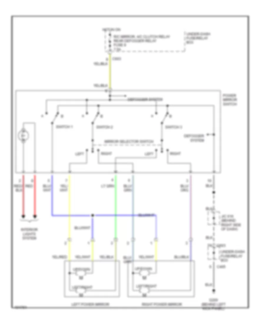
POWER MIRRORS
Power Mirrors Wiring Diagram for Acura 2.5TL 1998
 https://portal-diagnostov.com/license.html
Automotive Electricians Portal FZCO
Automotive Electricians Portal FZCO
https://portal-diagnostov.com/license.html
https://portal-diagnostov.com/license.html
Automotive Electricians Portal FZCO
Automotive Electricians Portal FZCOList of elements for Power Mirrors Wiring Diagram for Acura 2.5TL 1998:
- C405
- C603
- Defogger system
- G200 (behind left kick panel)
- Hot in on
- Interior lights system
- J/c 616 (behind right side of dash)
- Left
- Left power mirror
- Left/right
- Mirror selector switch
- Power mirror switch
- R/c mirror, a/c clutch relay rear defogger relay fuse 8 7.5a
- Red
- Right
- Right power mirror
- Switch 1
- Switch 2
- Switch 3
- Under-dash fuse/relay box
- Up/down
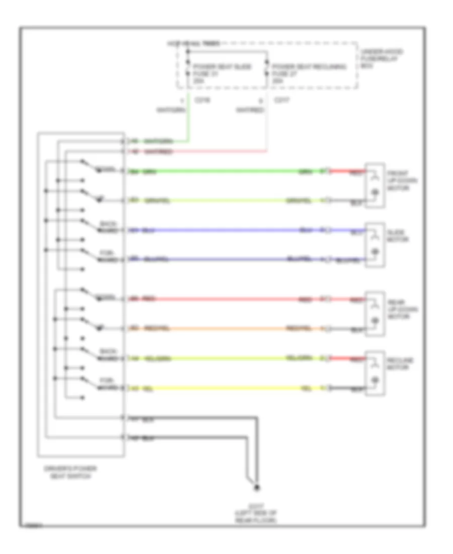
POWER SEATS
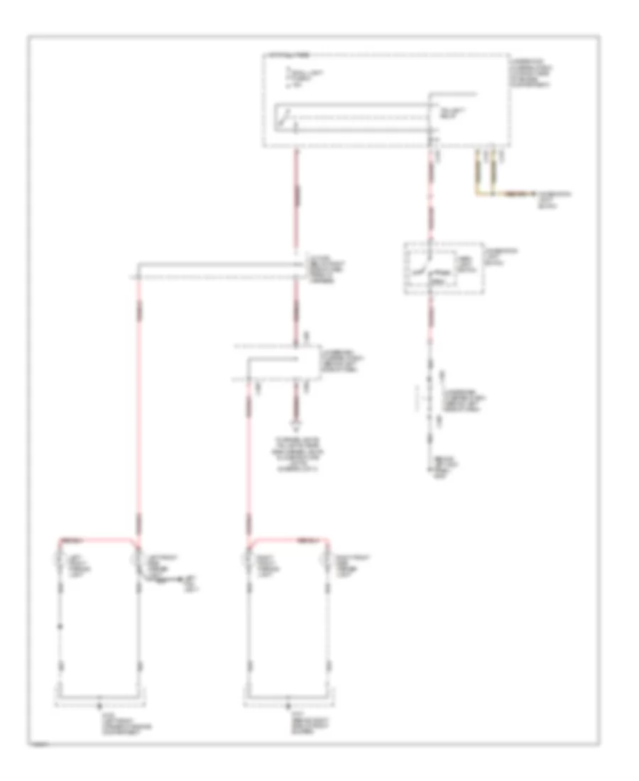
Driver Power Seat Wiring Diagram for Acura 2.5TL 1998
 https://portal-diagnostov.com/license.html
Automotive Electricians Portal FZCO
Automotive Electricians Portal FZCO
https://portal-diagnostov.com/license.html
https://portal-diagnostov.com/license.html
Automotive Electricians Portal FZCO
Automotive Electricians Portal FZCOList of elements for Driver Power Seat Wiring Diagram for Acura 2.5TL 1998:
- B6 red
- Back- ward
- C217
- C218
- Down
- Driver's power seat switch
- For- ward
- Front up-down motor
- G317 (left side of rear floor)
- Hot at all times
- Power seat reclining fuse 27 20a
- Power seat slide fuse 31 20a
- Rear up-down motor
- Recline motor
- Red
- Slide motor
- Under-hood fuse/relay box
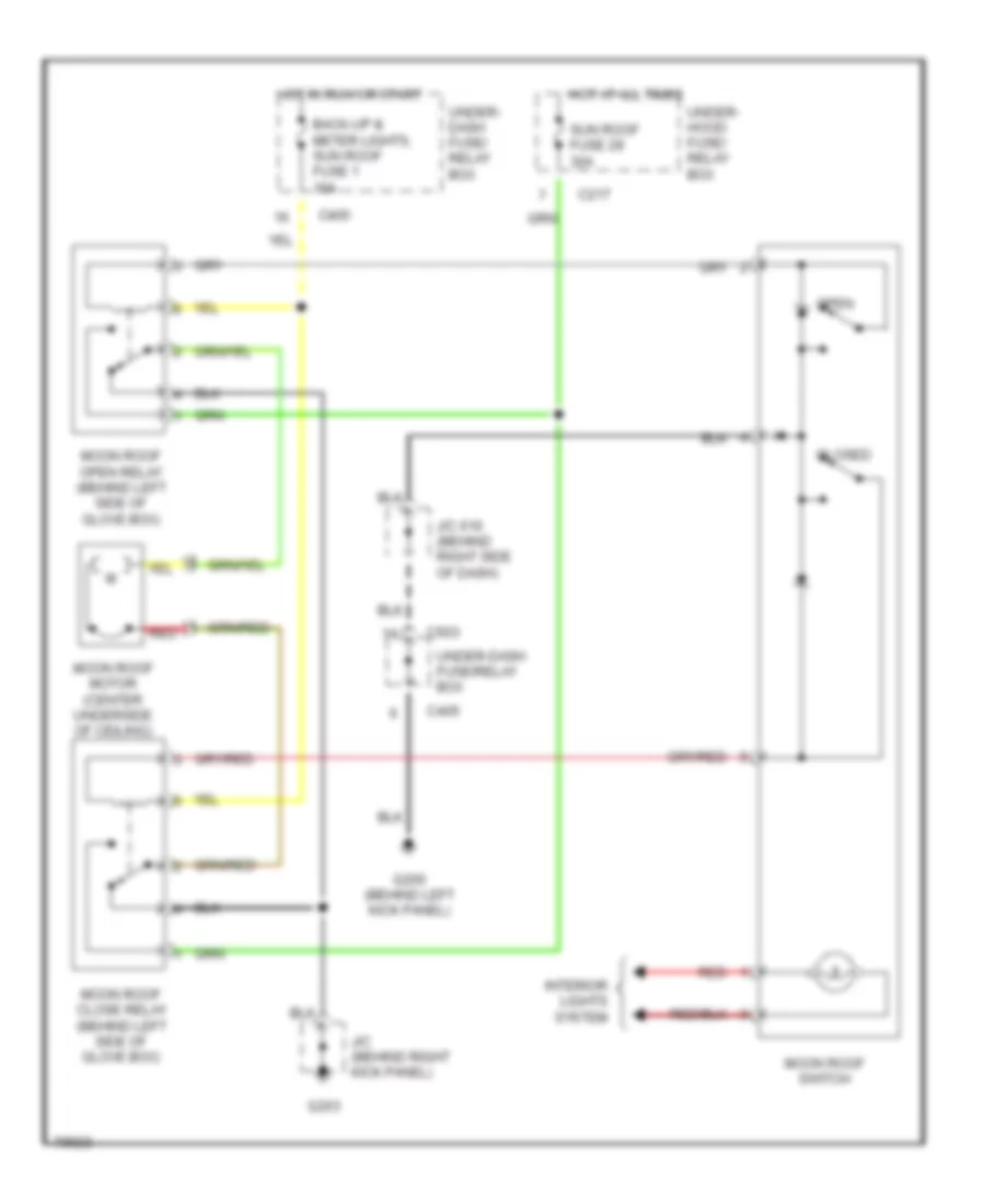
POWER TOP/SUNROOF
Moonroof Wiring Diagram for Acura 2.5TL 1998
 https://portal-diagnostov.com/license.html
Automotive Electricians Portal FZCO
Automotive Electricians Portal FZCO
https://portal-diagnostov.com/license.html
https://portal-diagnostov.com/license.html
Automotive Electricians Portal FZCO
Automotive Electricians Portal FZCOList of elements for Moonroof Wiring Diagram for Acura 2.5TL 1998:
- Back-up & meter lights, sun roof fuse 1 10a
- C217
- C405
- C603
- Closed
- G200 (behind left kick panel)
- G203
- Hot at all times
- Hot in run or start
- Interior lights system
- J/c (behind right kick panel)
- J/c 616 (behind right side of dash)
- Moon roof close relay (behind left side of glove box)
- Moon roof motor (center underside of ceiling)
- Moon roof open relay (behind left side of glove box)
- Moon roof switch
- Open
- Red
- Sun roof fuse 29 30a
- Under- dash fuse/ relay box
- Under- hood fuse/ relay box
- Under-dash fuse/relay box
POWER WINDOWS
Power Windows Wiring Diagram for Acura 2.5TL 1998
 https://portal-diagnostov.com/license.html
Automotive Electricians Portal FZCO
Automotive Electricians Portal FZCO
https://portal-diagnostov.com/license.html
https://portal-diagnostov.com/license.html
Automotive Electricians Portal FZCO
Automotive Electricians Portal FZCOList of elements for Power Windows Wiring Diagram for Acura 2.5TL 1998:
- A10
- A11
- A12
- A13
- A14
- A15
- A16
- Auto dn
- B12
- Batt in
- C216
- C217
- C405
- C406
- C504
- Control unit
- Driver's door sw in
- Driver's door switch
- Driver's power window motor
- Driver's switch
- Front passenger's door switch
- Front passenger's door switch input
- Front passenger's power window motor
- Front passenger's power window switch
- Front passenger's switch
- Fuse 1 (back-up lights, meter lights, sun roof) 10a
- Fuse 15 (battery) fuse 100a
- Fuse 24 (power window rr-r) 20a
- Fuse 25 (power window rr-l) 20a
- Fuse 26 (power window fr-r) 20a
- Fuse 28 (power window fr-l) 20a
- Fuse 37 (interior light fuse) 15a
- G101 (behind right side of front bumper)
- G200 (behind left kick panel)
- G200 (left kick panel)
- Gnd
- Hot at all times
- Hot in on or start
- Ign on
- Instrument cluster system
- Interior lights & anti-theft systems
- J/c c419 (above left kick panel)
- J/c c430 (below right side of dash, taped back to harness)
- J/c c463 (at right kick panel, taped back to harness)
- Left rear power window motor
- Left rear power window switch
- Left rear switch
- Main switch
- Off
- Power window key-off timer circuit (part of integrated control unit)
- Power window master switch
- Power window relay
- Pulser
- Red
- Right rear power window motor
- Right rear power window switch
- Right rear switch
- Rly cntl
- Under- dash fuse/ relay box
- Under- hood fuse/ relay box
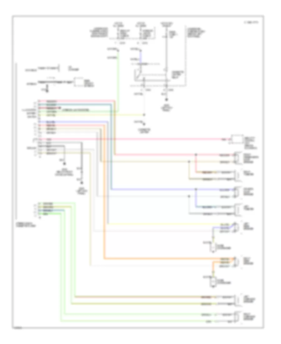
RADIO
Radio Wiring Diagram for Acura 2.5TL 1998
 https://portal-diagnostov.com/license.html
Automotive Electricians Portal FZCO
Automotive Electricians Portal FZCO
https://portal-diagnostov.com/license.html
https://portal-diagnostov.com/license.html
Automotive Electricians Portal FZCO
Automotive Electricians Portal FZCOList of elements for Radio Wiring Diagram for Acura 2.5TL 1998:
-
-
-
- (+) (-) (+)
- (+)
- (-)
- Antenna
- Back-up radio fuse 39 10a
- Battery
- C 1996 vftc
- C216
- C403
- C404
- C405
- Cd changer
- Cigarette lighter
- Cigarette lighter relay
- Din cable
- Driver's door speaker
- Front passenger's door speaker
- G200 (left kick panel)
- G302 (below front console panel)
- Ground
- Hot at all times
- Hot in acc or run
- Ignition
- Illumination
- Interior lights fuse 37 15a
- Interior lights system
- Left overhead speaker
- Left rear speaker
- Left tweeter
- Nca
- Noise condenser
- Pnk
- Radio fuse 11 10a
- Rear window antenna
- Right overhead speaker
- Right rear speaker
- Right tweeter
- Secutity control unit (behind glove box)
- Stereo radio/ cassette player
- Underdash fuse/relay box (behind left kick panel)
- Underhood fuse/relay box (right side of engine compt)
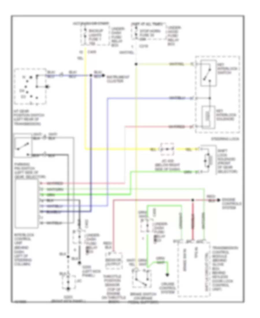
SHIFT INTERLOCK
Shift Interlock Wiring Diagram for Acura 2.5TL 1998
 https://portal-diagnostov.com/license.html
Automotive Electricians Portal FZCO
Automotive Electricians Portal FZCO
https://portal-diagnostov.com/license.html
https://portal-diagnostov.com/license.html
Automotive Electricians Portal FZCO
Automotive Electricians Portal FZCOList of elements for Shift Interlock Wiring Diagram for Acura 2.5TL 1998:
- (behind dash, left of steering column)
- (top of engine, on throttle body)
- A/t gear position switch (left rear of
- A22
- B12
- Backup lights fuse 1 10a
- Brake sw in
- Brake switch (on brake pedal support)
- C219
- C402
- C405
- C406
- Cruise control system
- Engine controls system
- G200 (left kick panel)
- G203 (right kick panel)
- Hot at all times
- Hot in on or start
- Instrument cluster
- Interlock control unit
- J/c
- J/c 430 (below right side of dash)
- Key interlock solenoid
- Key interlock switch
- Parking pin switch (left side of gear selector)
- Sensor output
- Shft lk circuit ctrl
- Shift lock solenoid (front of gear selector)
- Steering lock
- Stop,horn fuse 30 20a
- Throttle position sensor
- Tps in
- Transmission control module (behind glove box, behind keyless door lock control unit)
- Transmission)
- Under- dash fuse/ relay box
- Under- hood fuse/ relay box
STARTING/CHARGING
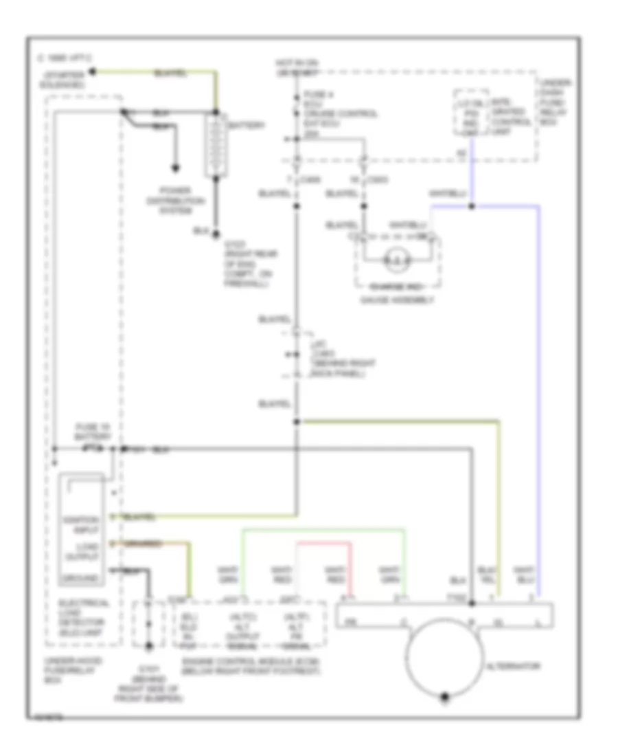
Charging Wiring Diagram for Acura 2.5TL 1998
 https://portal-diagnostov.com/license.html
Automotive Electricians Portal FZCO
Automotive Electricians Portal FZCO
https://portal-diagnostov.com/license.html
https://portal-diagnostov.com/license.html
Automotive Electricians Portal FZCO
Automotive Electricians Portal FZCOList of elements for Charging Wiring Diagram for Acura 2.5TL 1998:
- (altc) alt. output signal
- (altf) alt. fr signal
- (el) eld in- put
- (starter solenoid)
- A21
- Alternator
- Battery
- C 1995 vftc
- C406
- C603
- Charge ind.
- D16
- Electrical load detector (eld) unit
- Engine control module (ecm) (below right front footrest)
- Fuse 15 battery 100a
- Fuse 4 ecu cruise control eat ecu 20a
- G101 (behind right side of front bumper)
- G123 (right rear of eng. compt., on firewall)
- Gauge assembly
- Ground
- Hot in on or start
- Ignition input
- Inte- grated control unit
- J/c c463 (behind right kick panel)
- Lo oil psi ind. ckt.
- Load output
- Power distribution system
- T101
- T102
- Under- dash fuse/ relay box
- Under-hood fuse/relay box
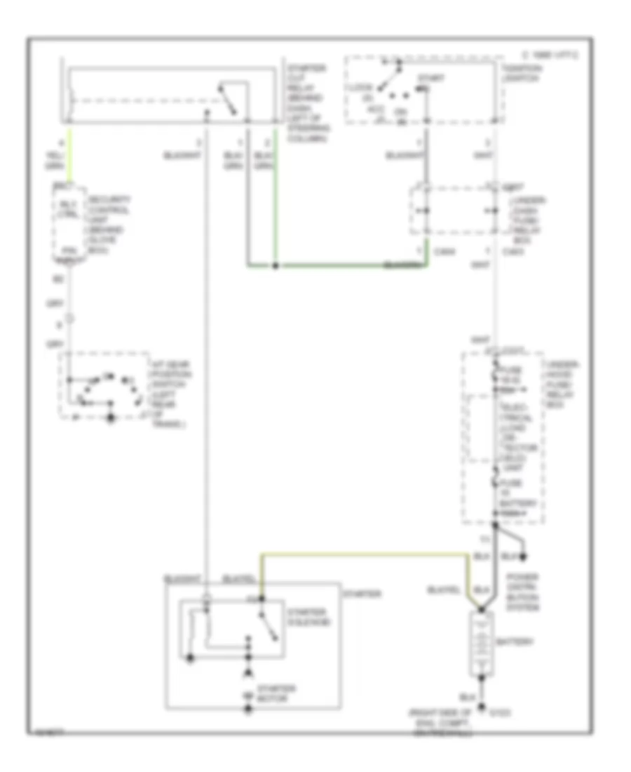
Starting Wiring Diagram for Acura 2.5TL 1998
 https://portal-diagnostov.com/license.html
Automotive Electricians Portal FZCO
Automotive Electricians Portal FZCO
https://portal-diagnostov.com/license.html
https://portal-diagnostov.com/license.html
Automotive Electricians Portal FZCO
Automotive Electricians Portal FZCOList of elements for Starting Wiring Diagram for Acura 2.5TL 1998:
- (right side of eng. compt., on firewall)
- A/t gear position switch (left rear of trans.)
- Acc (i)
- Battery
- C 1995 vftc
- C217
- C403
- C404
- C907
- Elec- trical load de- tector (eld) unit
- Fuse 18 ig 50a
- Fuse battery 100a
- G123
- Ignition switch
- Lock (0)
- On (ii)
- P/n input
- Power distri- bution system
- Rly. ctrl.
- Security control unit (behind glove box)
- Start (iii)
- Starter
- Starter cut relay (behind dash, left of steering column)
- Starter motor
- Starter solenoid
- Under- dash fuse/ relay box
- Under- hood fuse/ relay box
SUPPLEMENTAL RESTRAINTS
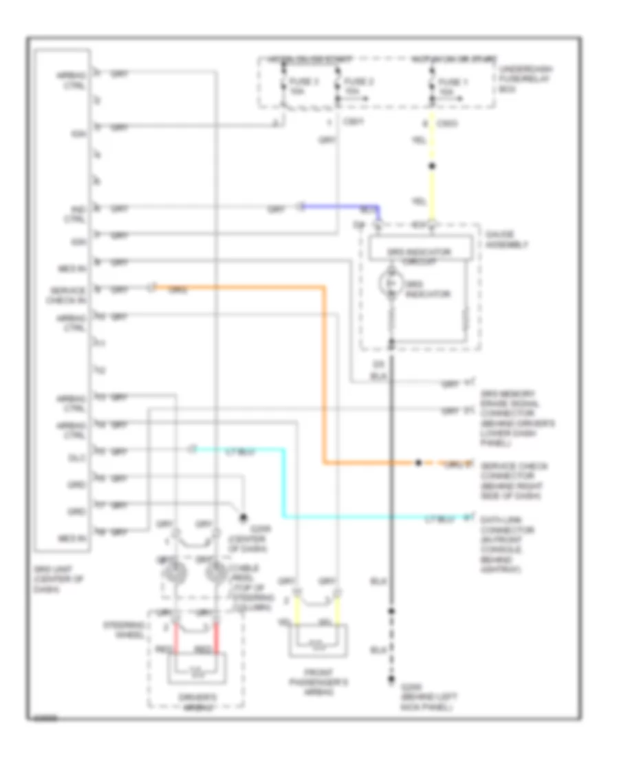
Supplemental Restraints Wiring Diagram for Acura 2.5TL 1998
 https://portal-diagnostov.com/license.html
Automotive Electricians Portal FZCO
Automotive Electricians Portal FZCO
https://portal-diagnostov.com/license.html
https://portal-diagnostov.com/license.html
Automotive Electricians Portal FZCO
Automotive Electricians Portal FZCOList of elements for Supplemental Restraints Wiring Diagram for Acura 2.5TL 1998:
- (center of dash)
- Airbag ctrl
- C603
- C801
- Cable reel (top of steering column)
- Data link connector (in front console, behind ashtray)
- Dlc
- Driver's airbag
- Front passenger's airbag
- Fuse 1 10a
- Fuse 2 15a
- Fuse 3 10a
- G200 (behind left kick panel)
- G206
- Gauge assembly
- Grd
- Hot in on or start
- Ign
- Ind ctrl
- Mes in
- Red
- Service check connector (behind right side of dash)
- Service check in
- Srs indicator
- Srs indicator circuit
- Srs memory erase signal connector (behind driver's lower dash panel)
- Srs unit (center of dash)
- Steering wheel
- Underdash fuse/relay box
TRANSMISSION
A/T Wiring Diagram for Acura 2.5TL 1998
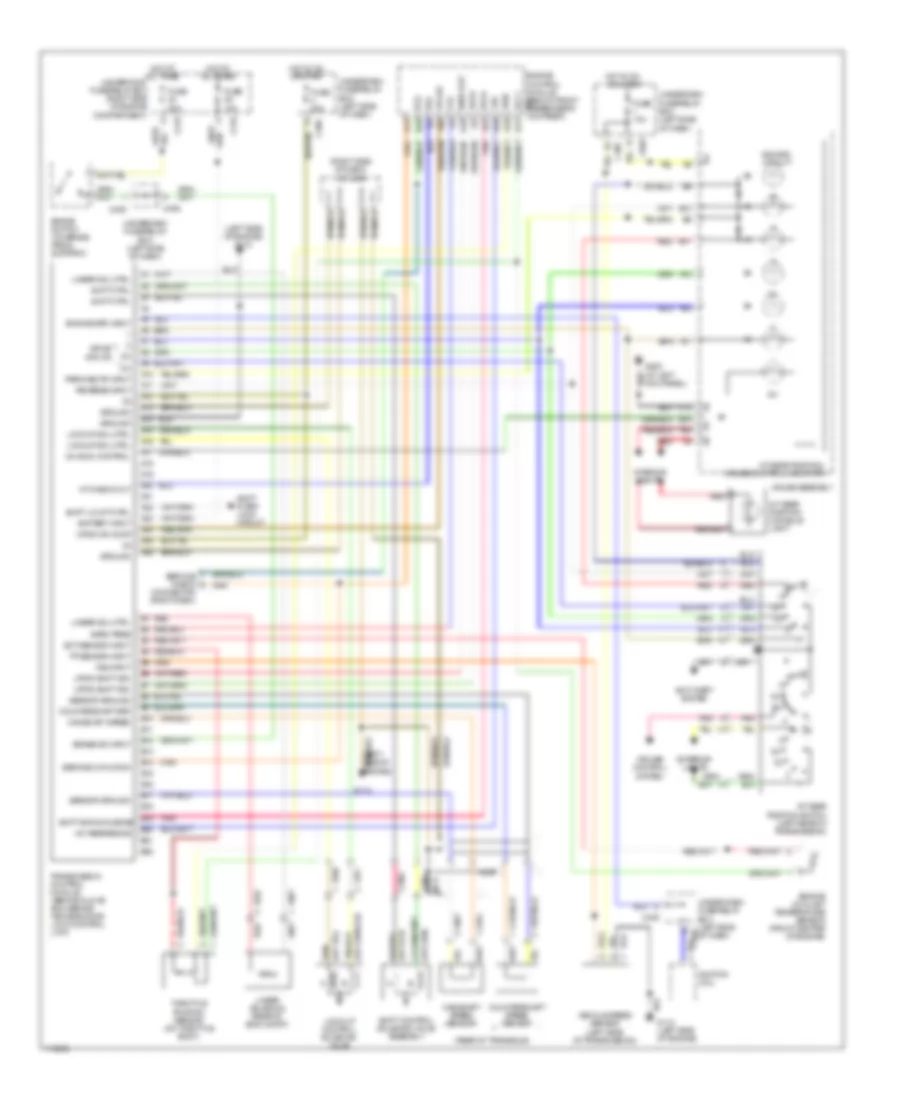 https://portal-diagnostov.com/license.html
Automotive Electricians Portal FZCO
Automotive Electricians Portal FZCO
https://portal-diagnostov.com/license.html
https://portal-diagnostov.com/license.html
Automotive Electricians Portal FZCO
Automotive Electricians Portal FZCOList of elements for A/T Wiring Diagram for Acura 2.5TL 1998:
- (left side of engine) g112
- (rear of transaxle)
- (right side of dash) j/c c436
- +5v reference
- A/t check out
- A/t gear position console light
- A/t gear position switch (left rear of transmission)
- A/t gear position/ cruise control indicator
- A10
- A11
- A12
- A13
- A14
- A15
- A16
- A17
- A18
- A19
- A20
- A21
- A22
- A23
- A24
- A25
- A26
- Afs a
- Afs b
- Anti-theft system
- At chk
- B10
- B11
- B12
- B13
- B14
- B15
- B16
- B17
- B18
- B19
- B20
- B21
- B22
- Baro out
- Baro pres
- Battery input
- Box (left side of dash)
- Brake sw input
- Brake switch (on brake pedal support)
- C12
- C216
- C219
- C405
- C406
- C603
- Connector (right dash)
- Countershaft spd
- Countershaft speed sensor
- Cruise control system
- D10
- D11
- D13
- D20
- D22
- D4 indic control
- Dimming circuit
- Drive inputs
- Ect sensor input
- Engine control module (below front passenger's footrest) sg1
- Engine coolant temperature sensor (front center of engine)
- Engine spd input
- Exterior lights
- Fas
- Ffs
- Fuse 10a
- Fuse 20a
- G112
- G112 (left side of engine)
- G200 (at left kick panel)
- Gauge assembly
- Ground
- Hot at all times
- Hot in on
- Hot in on or start
- Igi
- Ignition coil
- Interior lights
- Linear sol ctrl
- Linear solenoid (rear of eng compt)
- Lock-up control solenoid valve
- Lockup sol ctrl
- Mainshaft speed
- Mainshaft speed sensor
- Nca
- Or start
- Park/neutr input
- Pnk
- Red
- Reverse input
- Scs
- Sensor ground
- Service check
- Service chk conn
- Sg2
- Shift acknowledge
- Shift control solenoid valve assembly
- Shift ctrl
- Shift inter- lock circuit
- Shift lk ckt ctrl
- Throttle position sensor (on throttle body)
- Tp sensor input
- Transmission control module (behind glove box, behind keyless door lock control unit)
- Under-dash fuse/relay
- Underdash fuse/relay
- Underhood fuse/relay box (right side of engine compartment)
- Up/dn shift sig
- Up/down comp
- Vcc1
- Vehicle speed sensor (left side of transmission)
- Vref
- Vss input
WARNING SYSTEMS
Warning Systems Wiring Diagram for Acura 2.5TL 1998
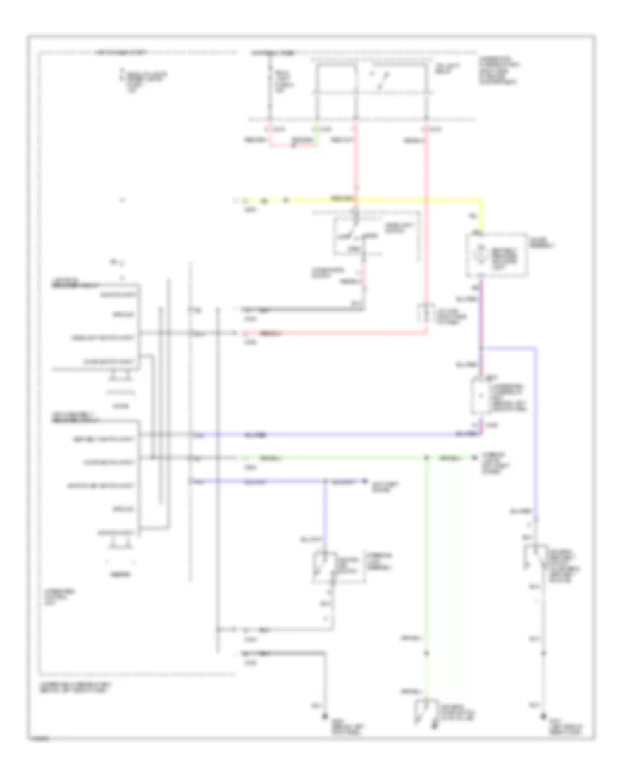 https://portal-diagnostov.com/license.html
Automotive Electricians Portal FZCO
Automotive Electricians Portal FZCO
https://portal-diagnostov.com/license.html
https://portal-diagnostov.com/license.html
Automotive Electricians Portal FZCO
Automotive Electricians Portal FZCOList of elements for Warning Systems Wiring Diagram for Acura 2.5TL 1998:
- A13
- A14
- Anti-theft system
- B13
- Back-up lights meter lights fuse 1 10a
- Beeper
- C216
- C219
- C402
- C405
- C406
- C504
- C603
- Chime
- Combination switch
- Door switch input
- Driver's door switch (in "b" pillar)
- Driver's seat belt switch (in driver's seat belt buckle)
- Fuse 21 15a
- G200 (behind left kick panel)
- G317 (left side of rear floor)
- Gauge assembly
- Ground
- Head
- Headlight switch
- Headlight switch input
- Hot at all times
- Hot in on or start
- Ignition input
- Ignition key switch
- Ignition key switch input
- Integrated control unit
- Interior lights, anti-theft system
- J/c c436 (right side of dash)
- Key-in/seatbelt reminder circuit
- Lights-on reminder circuit
- Off
- Park
- Seat belt reminder indicator light
- Seat belt switch input
- Small light
- Steering lock assembly
- Taillight relay
- Underdash fuse/relay box (behind left side of dash)
- Underhood fuse/relay box (right side of engine compartment)
WIPER/WASHER
Wiper/Washer Wiring Diagram for Acura 2.5TL 1998
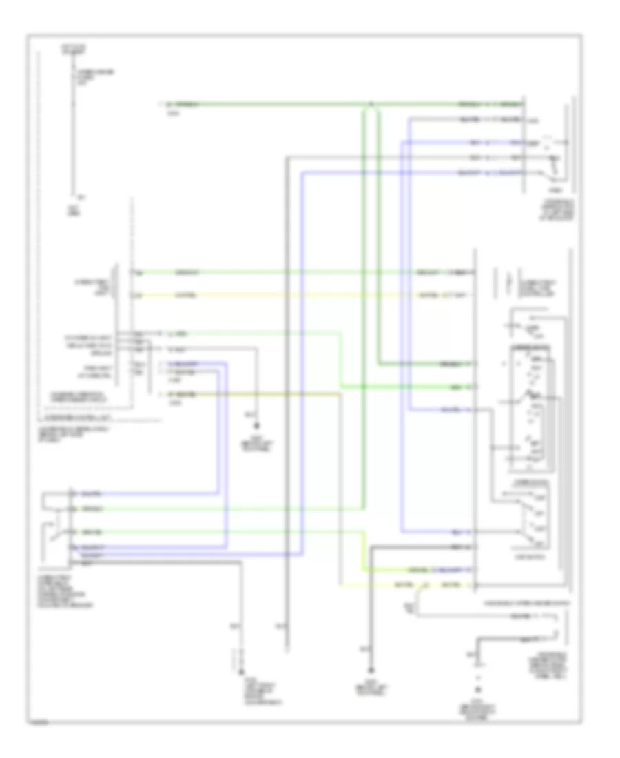 https://portal-diagnostov.com/license.html
Automotive Electricians Portal FZCO
Automotive Electricians Portal FZCO
https://portal-diagnostov.com/license.html
https://portal-diagnostov.com/license.html
Automotive Electricians Portal FZCO
Automotive Electricians Portal FZCOList of elements for Wiper/Washer Wiring Diagram for Acura 2.5TL 1998:
- B10
- B11
- C402
- C404
- C405
- Combined operation wiper/washer circuit
- G100 (left front corner of engine compartment)
- G101 (behind right side of front bumper)
- G200 (behind left kick panel)
- Ground
- High
- Hot in on or start
- Int
- Int wipe ctrl
- Int wiper on input
- Integrated control unit
- Intermittent dwell time controller
- Intermittent time input
- Intermittent wiper relay (on left rear corner of engine compartment, mounted on bracket)
- Low
- Mist
- Mist switch
- Not used
- Off
- Park
- Park input
- Run
- Underdash fuse/relay box (behind left side of dash)
- Wash
- Washer switch
- Windshield washer motor (behind panel, in right front wheel well)
- Windshield wiper motor (in left side of air scoop)
- Windshield wiper/washer switch
- Wiper switch
- Wiper/washer fuse 6 30a
- Wshld wash on in

 Čeština
 Dansk
Dansk Deutsch
 Ελληνικά
 English
 English
 Español
 Suomi
Suomi Français
 Français
 עברית
עברית Hrvatski
 Magyar
 Italiano
 한국어
한국어 Nederlands
 Polski
 Português
 Português
 Română
 Русский
 Slovenčina
 Slovenščina
 Svenska
 Türkçe
 中文 (中国)
