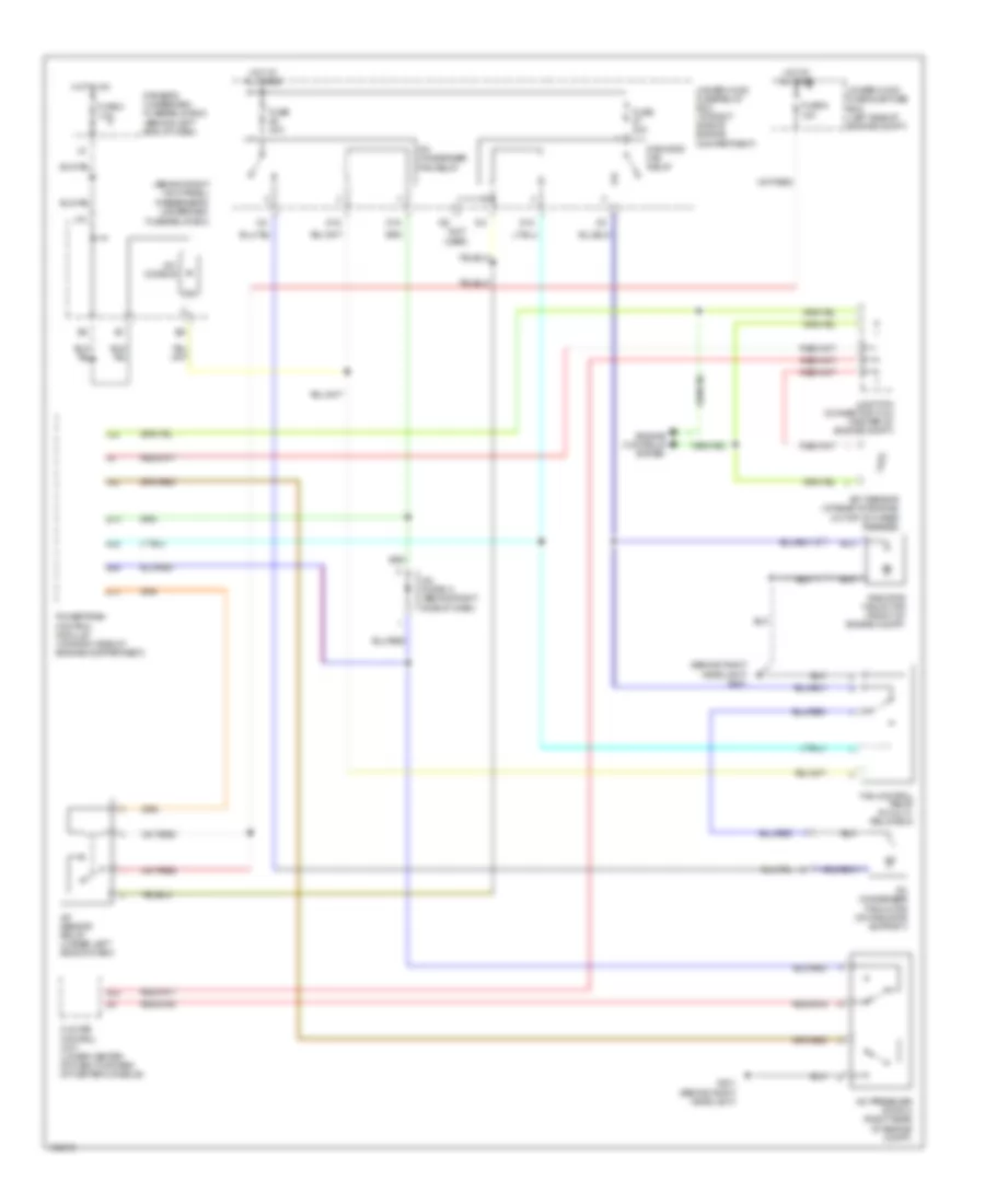
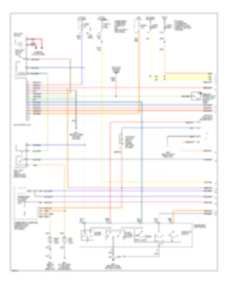
AIR CONDITIONING
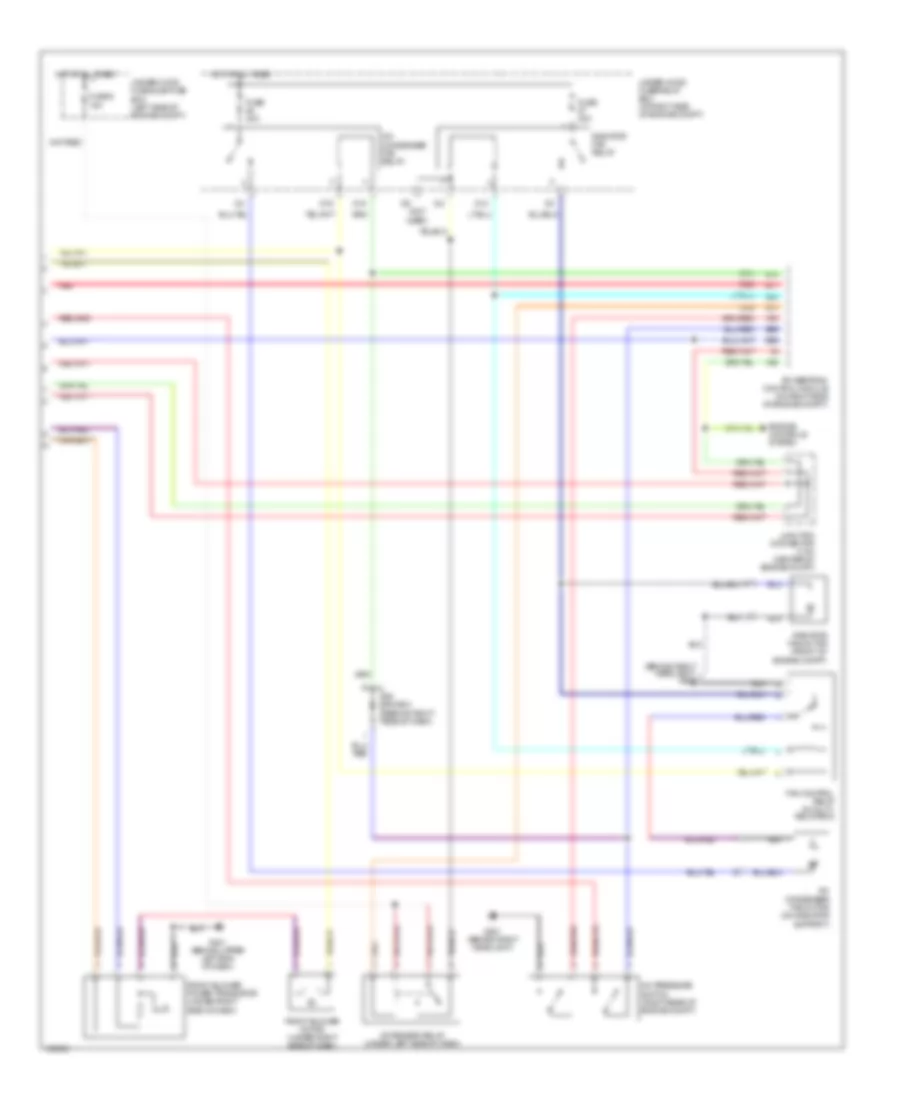
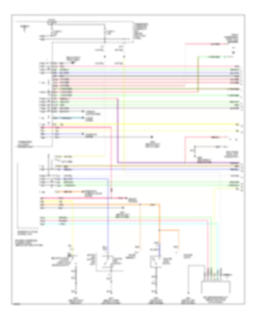
Automatic A/C Wiring Diagram (1 of 2) for Acura MDX 2004
 https://portal-diagnostov.com/license.html
Automotive Electricians Portal FZCO
Automotive Electricians Portal FZCO
https://portal-diagnostov.com/license.html
https://portal-diagnostov.com/license.html
Automotive Electricians Portal FZCO
Automotive Electricians Portal FZCO
List of elements for Automatic A/C Wiring Diagram (1 of 2) for Acura MDX 2004:
- (behind upper left end of dash)
- A/c compressor
- A/c compressor clutch
- A/c compressor clutch relay
- A/c diode b
- A10
- A11
- A12
- A13
- A14
- A15
- A16
- Amd-p
- Auto
- B10
- B11
- B12
- B13
- B14
- B15
- B16
- B17
- B18
- B19
- B20
- B21
- B22
- B23
- B24
- B25
- B26
- Climate control panel
- Climate control unit (lower center of dash, forward of center console)
- Clk 1
- D-gnd
- D11
- D14
- Data
- Defogger system
- Driver's underdash fuse/relay box (behind left end of dash)
- Ds0
- Ds1
- Ect sensor (at rear of engine, on top of water passage)
- Engine controls system
- Evaporator temperature sensor
- Front air mix control motor (on bottom of hvac assembly)
- Front blower motor relay
- Front mode control motor (under right side of dash)
- Frs
- Fuse 3 7.5a
- Fuse 40a
- Fuse 7.5a
- G201 (behind right headlight)
- G401
- Hot at all times
- Hot in on
- Illum
- In-car temperature sensor
- Interior lights system
- J/c c404 (under left side of dash)
- J15
- Latch
- M-cool
- M-def
- M-hot
- M-vent
- Mode 1
- Mode 2
- Mode 3
- Mode 4
- Navigation display unit (navigation) multi- information display unit (except navigation)
- Off
- Outside air temperature sensor
- Passenger's underdash fuse/relay box (behind right kick panel)
- Rear a/c circuit
- Rec
- Recirculation control motor (behind glove box)
- Red
- S-com
- S5v
- Sunlight sensor
- Under-hood fuse/relay box (at right side of engine compt)
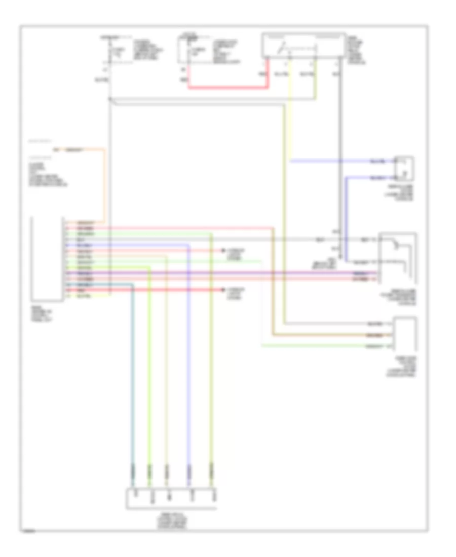
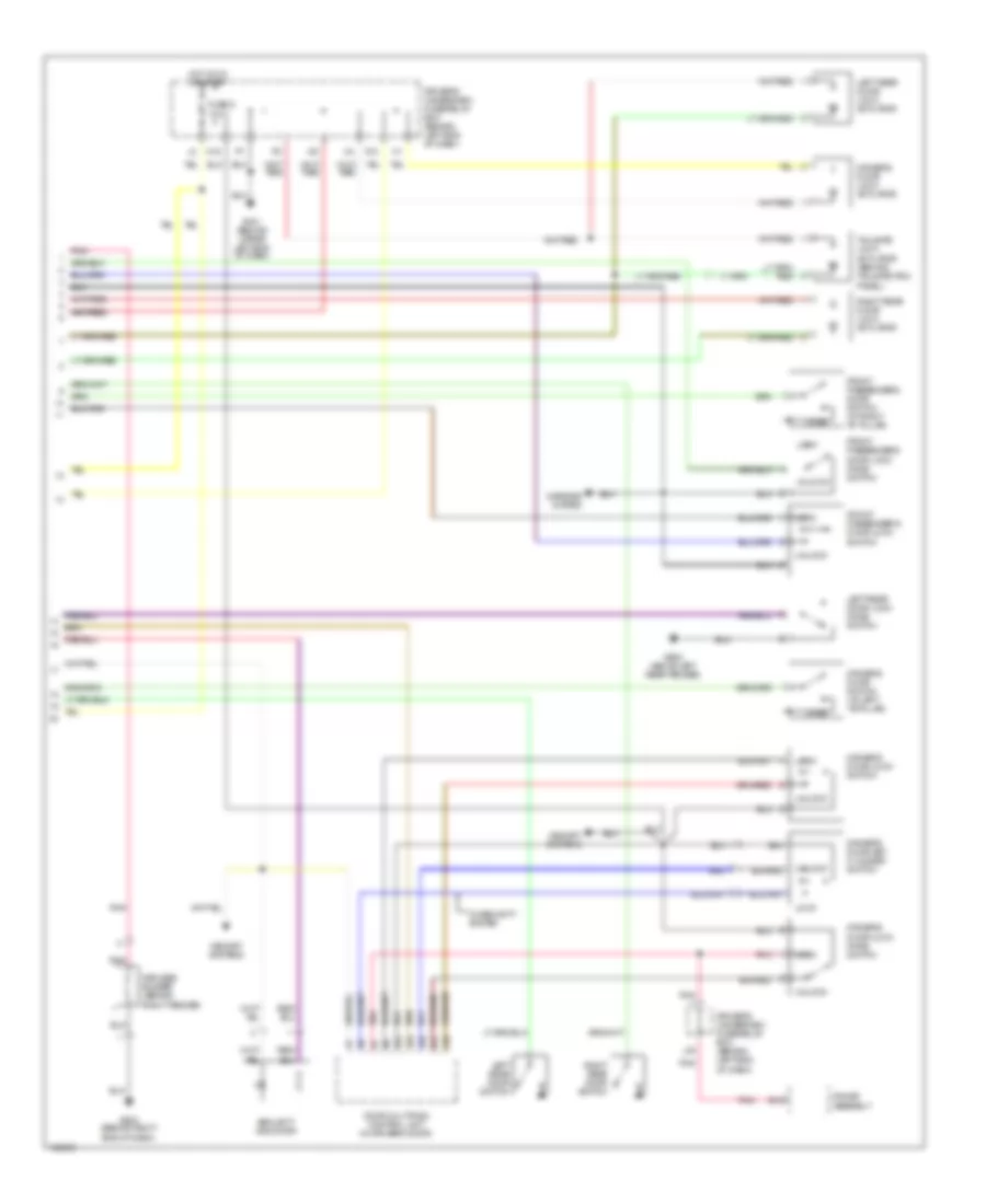
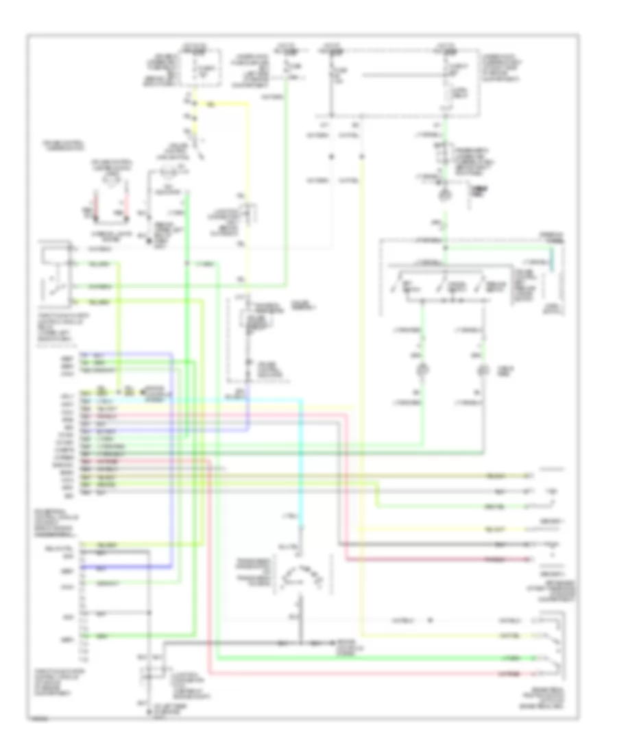
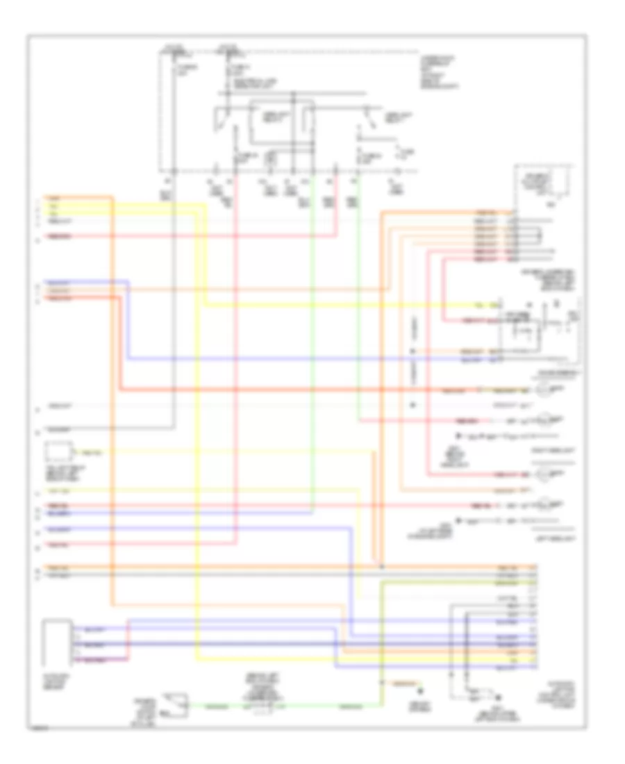
Automatic A/C Wiring Diagram (2 of 2) for Acura MDX 2004
 https://portal-diagnostov.com/license.html
Automotive Electricians Portal FZCO
Automotive Electricians Portal FZCO
https://portal-diagnostov.com/license.html
https://portal-diagnostov.com/license.html
Automotive Electricians Portal FZCO
Automotive Electricians Portal FZCOList of elements for Automatic A/C Wiring Diagram (2 of 2) for Acura MDX 2004:
- (behind right headlight) g201
- (not used)
- A/c condenser fan motor (on radiator support)
- A/c condenser fan relay
- A/c diode a (behind right side of dash)
- A/c pressure switch (right rear of engine compt)
- A/f sensor relay (under left side of dash)
- A28
- A30
- B10
- B11
- B14
- B26
- B28
- B56
- D12
- D15
- D16
- Engine controls system
- Fan control relay (in multi- relay box)
- Front blower motor (under right side of dash)
- Front blower power transistor (under right side of dash)
- Fuse 30a
- Fuse 9 15a
- G201 (behind right headlight)
- G401 (behind upper left end of dash)
- Hot at all times
- Junction connector c104 (center of engine compt)
- Powertrain control module (on right side of engine compt)
- Radiator fan motor (front of engine compt)
- Radiator fan relay
- Red
- Under-hood fuse sub-fuse box (left side of engine compt)
- Under-hood fuse/relay box (at right side of engine compt)
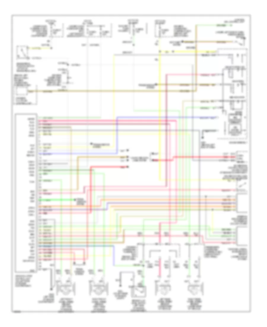
Rear A/C Wiring Diagram for Acura MDX 2004
 https://portal-diagnostov.com/license.html
Automotive Electricians Portal FZCO
Automotive Electricians Portal FZCO
https://portal-diagnostov.com/license.html
https://portal-diagnostov.com/license.html
Automotive Electricians Portal FZCO
Automotive Electricians Portal FZCOList of elements for Rear A/C Wiring Diagram for Acura MDX 2004:
- Amd-p
- Climate control unit (lower center of dash, forward of center console)
- Driver's underdash fuse/relay box (behind left end of dash)
- Fuse 3 7.5a
- Fuse 52 30a
- G501 (behind left end of dash)
- Hot at all times
- Hot in on
- Interior lights system
- M-cool
- M-hot
- Rear air mix control motor (under center console panel)
- Rear blower motor (under center console)
- Rear blower motor relay (under center console)
- Rear blower power transistor (under center console)
- Rear heater-a/c control panel unit
- Rear mode control motor (under center console panel)
- Red
- S-com
- Ssv
- Under-hood fuse/relay box (at right side of engine compt)
ANTI-LOCK BRAKES
Anti-lock Brakes Wiring Diagram for Acura MDX 2004
 https://portal-diagnostov.com/license.html
Automotive Electricians Portal FZCO
Automotive Electricians Portal FZCO
https://portal-diagnostov.com/license.html
https://portal-diagnostov.com/license.html
Automotive Electricians Portal FZCO
Automotive Electricians Portal FZCOList of elements for Anti-lock Brakes Wiring Diagram for Acura MDX 2004:
- (behind left end of dash) driver's under-dash fuse/relay box
- (canada) drl control unit
- (not used)
- (under left side of dash) parking brake switch
- +b-fsr
- +b-mr
- A18
- A19
- Abs ind
- Abs indicator
- Abs indicator circuit
- Act
- Anti-theft system
- Auxiliary fuse holder 2
- B15
- B16
- B21
- B22
- B39
- Bft
- Bk sw
- Brake fluid level switch (left side of engine compartment)
- Brake pedal position switch (at top of brake pedal arm)
- Brake system ind
- C10
- C13
- Can-h
- Can-l
- Canh
- Canl
- Computer data lines system
- Cruise control main switch/vsa off switch
- D15
- Diag-k
- Driver's multiplex control unit
- Driver's under-dash fuse/relay box (behind left end of dash)
- Driver's underdash fuse/relay box (behind left end of dash)
- Ebd
- F13
- F14
- Flp
- Fls+
- Fls-
- Frp
- Frs+
- Frs-
- Fuse 2 40a
- Fuse 3 30a
- Fuse 47 20a
- Fuse 9 10a
- Fuse 92 7.5a
- G301 (at left rear of engine compt)
- G302 (left side of engine compartment)
- G501 (behind left end of dash)
- Gauge assembly
- Glat
- Glon
- Gnd
- Hot at all times
- Hot in on or start
- I11
- Ig1
- K14
- Left front wheel speed sensor (left side of engine compartment)
- Left rear wheel speed sensor (under rear of vehicle)
- M10
- M20
- Passenger's underdash fuse/relay box (behind right kick panel)
- Pnk
- Powertrain control module (on right side of engine compartment)
- Red
- Right front wheel speed sensor (right side of engine compartment)
- Right rear wheel speed sensor (under rear of vehicle)
- Rlp
- Rls+
- Rls-
- Rrp
- Rrs+
- Rrs-
- Scs
- Sgnd
- Steering angle sensor (in steering column cover)
- Stop
- Str-a
- Str-b
- Str-d
- Svcc
- Trans- missions system
- Transmissions system
- Under-hood fuse sub-fuse box (left side of engine compt)
- Under-hood fuse/relay box (at right side of engine compartment)
- Vsa
- Vsa activation ind
- Vsa modulator control unit (on left side of engine compartment)
- Vsa off sw
- Vsa system ind
- Vsa system indicator circuit
- Yaw
- Yaw rate-lateral acceleration sensor (under middle of dash)
ANTI-THEFT
Immobilizer Wiring Diagram for Acura MDX 2004
 https://portal-diagnostov.com/license.html
Automotive Electricians Portal FZCO
Automotive Electricians Portal FZCO
https://portal-diagnostov.com/license.html
https://portal-diagnostov.com/license.html
Automotive Electricians Portal FZCO
Automotive Electricians Portal FZCOList of elements for Immobilizer Wiring Diagram for Acura MDX 2004:
- (at right side of cargo area, behind rear side trim panel) vtm-4 control unit
- (lower left
- (under left side of dash)
- A17
- A18
- Auxiliary fuse holder 2
- B12
- B13
- B15
- B41
- Behind lower
- C11
- Cover)
- Data link connector
- Driver's multiplex control unit
- Driver's underdash fuse/relay box (behind left end of dash)
- Drl control unit (canada)
- Engine controls system
- Fuel pump
- Fuel tank unit (middle of floor)
- Fuse 1 15a
- Fuse 13 7.5a
- Fuse 46 15a
- Fuse 7.5a
- G101 (at left rear of engine)
- G15
- G401 (behind upper left end of dash)
- G601 (below left front seat)
- Gauge assembly
- Hot at all times
- Hot in on or start
- I12
- Immobilizer control unit receiver (in steering column cover)
- Immobilizer system indicator
- Junction connector c103 (center of engine compt)
- Of engine compt)
- Parking brake switch (under left side of dash)
- Passenger's underdash fuse/relay box (behind right kick panel)
- Pcm (on right side
- Pgm-fi main relay 1
- Pgm-fi main relay 2 (under left side of dash)
- Pnk
- Red
- Side of dash,
- Under-hood fuse/relay box (at right side of engine compt)
Power Door Locks Wiring Diagram (1 of 2) for Acura MDX 2004
 https://portal-diagnostov.com/license.html
Automotive Electricians Portal FZCO
Automotive Electricians Portal FZCO
https://portal-diagnostov.com/license.html
https://portal-diagnostov.com/license.html
Automotive Electricians Portal FZCO
Automotive Electricians Portal FZCOList of elements for Power Door Locks Wiring Diagram (1 of 2) for Acura MDX 2004:
- (below right front seat) g651
- (not used)
- A10
- A11
- A12
- A13
- A14
- A15
- A16
- A17
- A21
- A22
- A23
- A24
- Antenna
- B11
- B14
- B18
- B19
- B21
- B22
- C14
- C16
- C20
- Driver's multiplex control unit
- Driver's underdash fuse/relay box (behind left end of dash)
- E10
- E15
- E17
- Exterior & interior lights system
- Front passenger's door lock actuator
- Fuse 12 20a
- Fuse 13 7.5a
- G15
- G201 (behind right headlight)
- G401 (behind upper left end of dash)
- G501 (behind left end of dash)
- G503 (behind right end of dash)
- G602 (above left rear fender)
- G652 (above right rear fender)
- Gauge assembly
- H14
- Horns system
- Hot at all times
- I12
- I14
- Ignition key switch
- Ignition key switch/ key light
- Interior lights system
- Keyless receiver unit (behind right side of glove box)
- M19
- Memory systems
- Navigation system
- Passenger's multiplex control unit
- Passenger's underdash fuse/relay box (behind right kick panel)
- Pnk
- Right rear door lock knob switch
- Security hood switch (front of engine compt)
- Tailgate latch switch
- Tailgate lights
Power Door Locks Wiring Diagram (2 of 2) for Acura MDX 2004
 https://portal-diagnostov.com/license.html
Automotive Electricians Portal FZCO
Automotive Electricians Portal FZCO
https://portal-diagnostov.com/license.html
https://portal-diagnostov.com/license.html
Automotive Electricians Portal FZCO
Automotive Electricians Portal FZCOList of elements for Power Door Locks Wiring Diagram (2 of 2) for Acura MDX 2004:
- A12
- A15
- A16
- A17
- A18
- B12
- Door multiplex control unit (in driver's door)
- Driver's door key cylinder switch
- Driver's door lock actuator
- Driver's door lock knob switch
- Driver's door lock switch
- Driver's door switch (at left "b"pillar)
- Driver's underdash fuse/relay box (behind left end of dash)
- Front passenger's door lock knob switch
- Front passenger's door lock switch
- Front passenger's door switch (at right "b" pillar)
- Fuse 9 10a
- G401 (behind upper left end of dash)
- G503 (behind right end of dash)
- G602 (above left rear fender)
- Gauge assembly
- H16
- Hot in on or start
- K13
- Keyless buzzer (behind right fender)
- L20
- Left rear door lock actuator
- Left rear door lock knob switch
- Left rear door switch
- Lock
- Memory systems
- Mirrors system
- Open
- Pnk
- Right rear door lock actuator
- Right rear door switch
- Security indicator
- Tailgate lock actuator (behind tailgate trim panel)
- Unlock
- W/ security system
BODY CONTROL MODULES
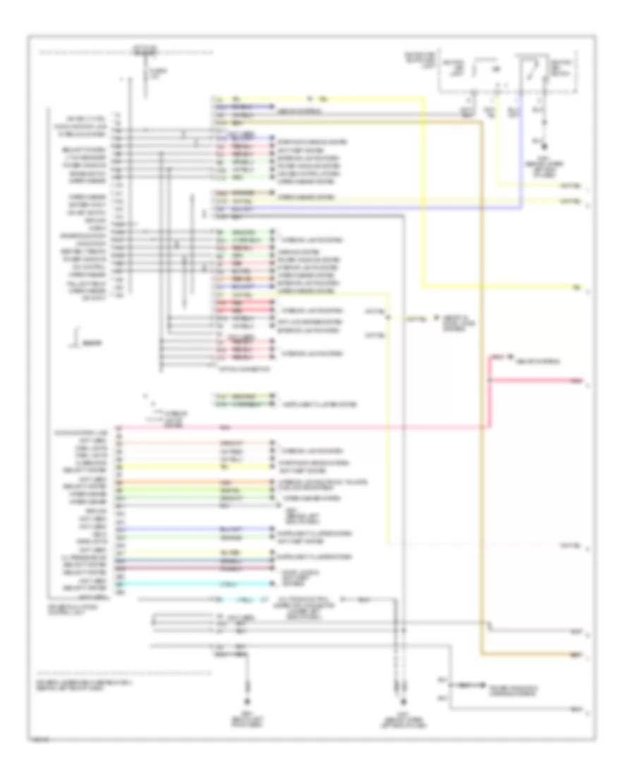
Body Control Modules Wiring Diagram (1 of 2) for Acura MDX 2004
 https://portal-diagnostov.com/license.html
Automotive Electricians Portal FZCO
Automotive Electricians Portal FZCO
https://portal-diagnostov.com/license.html
https://portal-diagnostov.com/license.html
Automotive Electricians Portal FZCO
Automotive Electricians Portal FZCOList of elements for Body Control Modules Wiring Diagram (1 of 2) for Acura MDX 2004:
- (not used)
- A10
- A11
- A12
- A13
- A14
- A15
- A16
- A17
- A18
- A19
- A20
- A21
- A22
- A23
- A24
- Alternator
- Anti-lock brakes system
- Anti-theft system
- B10
- B11
- B12
- B13
- B14
- B15
- B16
- B17
- B18
- B19
- B20
- B21
- B22
- Battery input
- Beeper
- Brake switch
- Check
- Communication line
- Cruise control system
- D15
- D17
- D2o
- Dash lights
- Dim control
- Door locks & anti-theft systems
- Driver's door sw
- Driver's multiplex control unit
- Driver's underdash fuse/relay box (behind left end of dash)
- E10
- Exterior lights system
- F10
- Fuse 9 10a
- G401 (behind upper left end of dash)
- G501 (behind left end of dash)
- G601 (below left front seat)
- Ground
- H14
- H16
- Headlights
- Hot in on or start
- Ign input
- Ign key lt ctrl
- Ign key switch
- Ignition key light
- Ignition key switch
- Ignition key switch/key light
- Instrument cluster system
- Interior lights & trunk, tailgate, fuel doors systems
- Interior lights system
- Interlock system
- J13
- J14
- J15
- K10
- K12
- K15
- K16
- L15
- L18
- Lr door sw
- Lt on reminder
- M12
- M19
- M20
- Memory & door locks systems
- Memory systems
- Multiplex control inspection connector (under left side of dash)
- Oil pressure ind
- Option connector
- Pnk
- Power windows
- Power windows & mirrors systems
- Power windows system
- Red
- Seat belt remind
- Security system
- Starting/charging system
- Taillight relay
- Vss in
- Warning system
- Wiper/washer
- Wiper/washer system
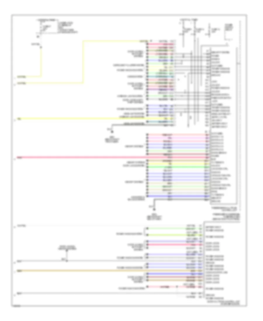
Body Control Modules Wiring Diagram (2 of 2) for Acura MDX 2004
 https://portal-diagnostov.com/license.html
Automotive Electricians Portal FZCO
Automotive Electricians Portal FZCO
https://portal-diagnostov.com/license.html
https://portal-diagnostov.com/license.html
Automotive Electricians Portal FZCO
Automotive Electricians Portal FZCOList of elements for Body Control Modules Wiring Diagram (2 of 2) for Acura MDX 2004:
- (not used)
- A10
- A11
- A12
- A13
- A14
- A15
- A16
- A17
- A18
- A19
- A20
- A21
- A22
- A23
- A24
- B10
- B11
- B12
- B13
- B14
- B15
- B16
- B17
- B18
- B19
- B20
- B21
- B22
- Battery input
- Bus
- C11
- C12
- C14
- C16
- C20
- Common
- Communication line
- Door locks
- Door locks & anti- theft systems
- Door locks & anti-theft systems
- Door locks & memory systems
- Door locks system
- Door multiplex control unit (in driver's door)
- Dpms
- E15
- E17
- E18
- Entry lt ctrl
- Fuse 12 20a
- Fuse 13 7.5a
- Fuse 47 20a
- Fuse 5 20a
- G503 (behind right end of dash)
- G651 (below right front seat)
- Ground
- H14
- Headlight relay 1
- Headlights system
- Horns system
- Hot at all times
- I12
- I14
- Ign input
- Instrument cluster system
- Interior lights system
- Knob in
- L/r motor ctrl
- Lock
- Memory systems
- Navigation & sound systems
- Pass door switch
- Passenger's multiplex control unit
- Passenger's underdash fuse/relay box (behind right kick panel)
- Pnk
- Power
- Power window relay
- Power windows
- Power windows system
- Rr door switch
- Security
- Security system
- Swing sens in
- Switch 1 in
- Switch 2 in
- Switch 3 in
- Tilt sens in
- Under-hood fuse/relay box (at right side of engine compt)
- Unlock
- Up/dn motor ctrl
COMPUTER DATA LINES
Computer Data Lines Wiring Diagram for Acura MDX 2004
 https://portal-diagnostov.com/license.html
Automotive Electricians Portal FZCO
Automotive Electricians Portal FZCO
https://portal-diagnostov.com/license.html
https://portal-diagnostov.com/license.html
Automotive Electricians Portal FZCO
Automotive Electricians Portal FZCOList of elements for Computer Data Lines Wiring Diagram for Acura MDX 2004:
- (above right rear fender) g652
- (behind glove box) junction connector c501
- (behind upper left end of dash) g401
- A11
- A15
- A17
- A18
- A20
- A22
- A24
- A25
- A26
- B10
- B15
- B16
- B17
- B34
- B54
- Can high
- Can low
- Data link connector (lower left side of dash, behind lower cover)
- Diag n
- Diag p
- Driver's multiplex control unit
- Driver's power seat control unit (w/ memory) (under driver's seat)
- Driver's underdash fuse/relay box (behind left end of dash)
- Except navigation
- Fuse 15a
- G101 (at left rear of engine)
- G401 (behind upper left end of dash)
- G652 (above right rear fender)
- G801 (under center of dash)
- Hot at all times
- Immobilizer control unit receiver (in steering column cover)
- Junction connector c404 (under left side of dash)
- Mes connector (under left side of dash)
- Multiplex control inspection connector (under left side of dash)
- Navigation
- Navigation service check connector (under front passenger's seat)
- Navigation unit (under right front seat)
- Passenger's multiplex control unit
- Passenger's underdash fuse/relay box (behind right kick panel)
- Pnk
- Powertrain control module (pcm) (on right side of engine compt)
- Red
- Srs unit (behind lower center of dash)
- Tpms receiver unit (under left side of dash)
- Under-hood fuse/relay box (at right side of engine compt)
- Vsa modulator control unit (on left side of engine compt)
- Vtm-4 control unit (at right side of cargo area, behind rear side trim panel)
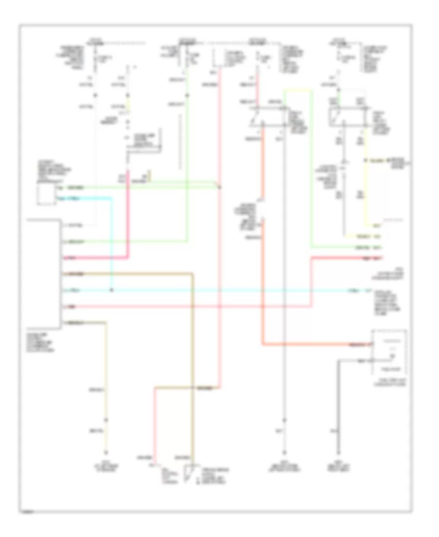
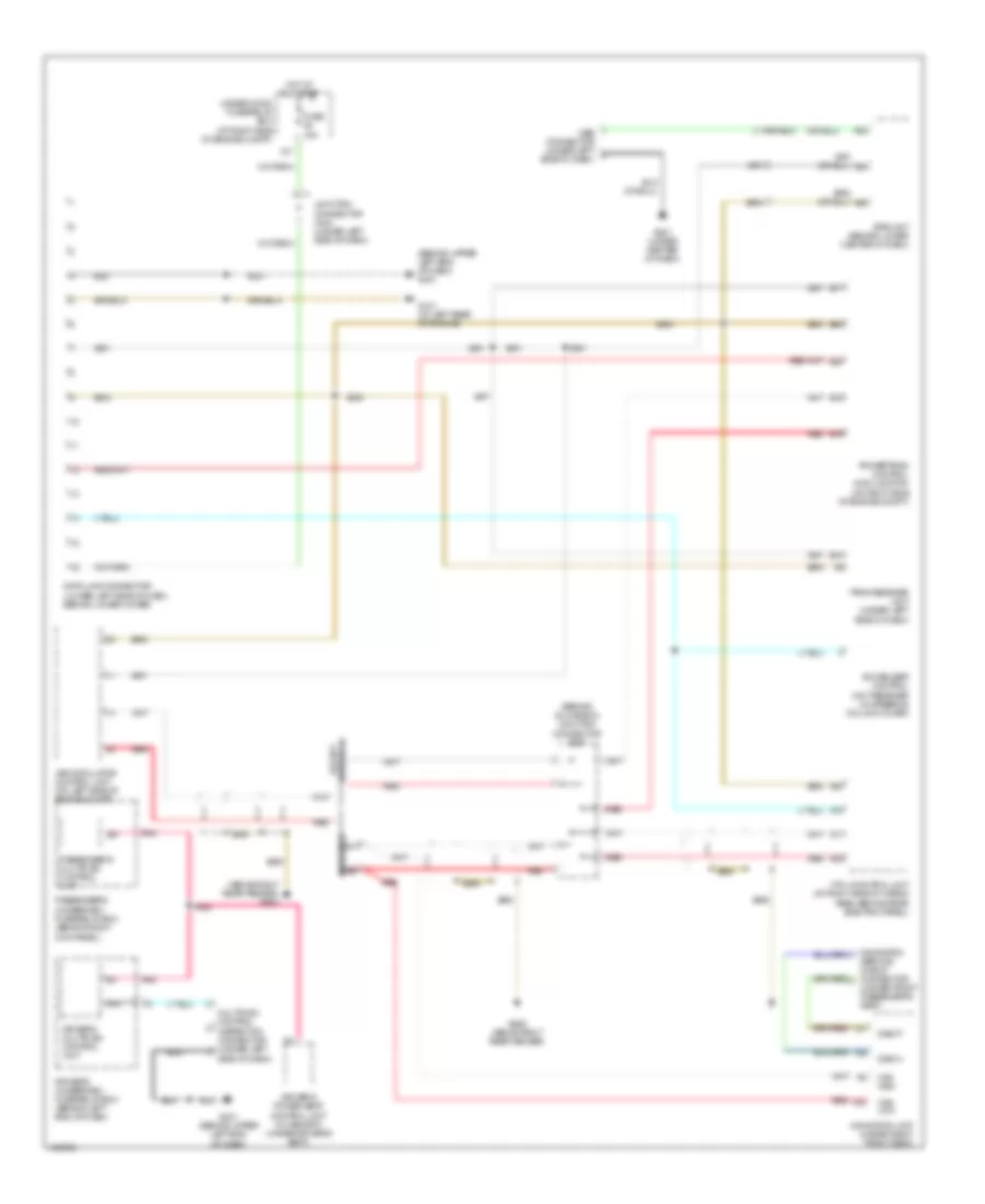
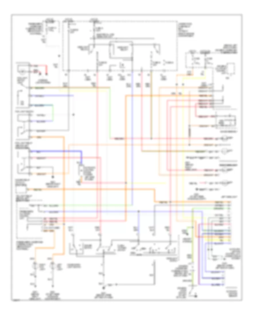
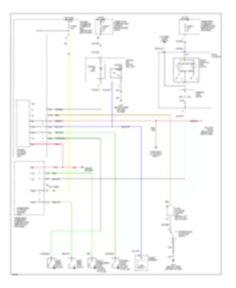
COOLING FAN
Cooling Fan Wiring Diagram for Acura MDX 2004
 https://portal-diagnostov.com/license.html
Automotive Electricians Portal FZCO
Automotive Electricians Portal FZCO
https://portal-diagnostov.com/license.html
https://portal-diagnostov.com/license.html
Automotive Electricians Portal FZCO
Automotive Electricians Portal FZCOList of elements for Cooling Fan Wiring Diagram for Acura MDX 2004:
- (behind right headlight) g201
- (behind right kick panel)
- (not used)
- A/c condenser fan motor (on radiator support)
- A/c condenser fan relay
- A/c diode a (behind right side of dash)
- A/c diode b
- A/c pressure switch (right rear of engine compt)
- A/f sensor relay (under left side of dash)
- A28
- A30
- B10
- B14
- B22
- B28
- B56
- Climate control unit (lower center of dash, forward of center console)
- D12
- D15
- D16
- Driver's underdash fuse/relay box (behind left end of dash)
- Ect sensor (at rear of engine, on top of water passage)
- Engine controls system
- Fan control relay (in multi- relay box)
- Fuse 3 7.5a
- Fuse 30a
- Fuse 9 15a
- G201 (behind right headlight)
- Hot at all times
- Hot in on
- J15
- Junction connector c104 (center of engine compt)
- Passenger's underdash fuse/relay box
- Powertrain control module (on right side of engine compartment)
- Radiator fan motor (front of engine compt)
- Radiator fan relay
- Under-hood fuse sub-fuse box (left side of engine compt)
- Under-hood fuse/relay box (at right side of engine compartment)
CRUISE CONTROL
Cruise Control Wiring Diagram for Acura MDX 2004
 https://portal-diagnostov.com/license.html
Automotive Electricians Portal FZCO
Automotive Electricians Portal FZCO
https://portal-diagnostov.com/license.html
https://portal-diagnostov.com/license.html
Automotive Electricians Portal FZCO
Automotive Electricians Portal FZCOList of elements for Cruise Control Wiring Diagram for Acura MDX 2004:
- "on" indicator
- (at left rear of engine) g101
- (behind upper left end of dash) g401
- A11
- A17
- A29
- App sensor (at right rear side of engine compartment)
- Aps1
- Aps2
- Atp f
- B12
- B14
- B24
- B29
- B30
- B31
- B33
- B35
- B36
- B37
- B38
- B39
- B43
- B44
- B45
- Bksw
- Bkswnc
- Brake pedal position switch (at top of brake pedal arm)
- C10
- Cable cable reel reel
- Cable reel
- Cancel switch
- Ccind
- Ccmsw
- Ccress
- Ccsets
- Cruise control indicator
- Cruise control main switch
- Cruise control master switch
- Cruise control master switch light
- Cruise control set/ resume/ cancel switch
- Cruise dimming circuit
- Driver's underdash fuse/relay box (behind left end of dash)
- Engine controls system
- Fuse 15a
- Fuse 47 20a
- Fuse 9 10a
- Gauge assembly
- Gauges & indicators
- Gnd
- Horn relay
- Horn switch
- Hot at all times
- Hot in on or start
- Interior lights system
- Junction connector c104 (center of engine compt)
- Junction connector c501 (behind glove box)
- Minhi
- Mrly
- Passenger's underdash fuse/relay box (behind right kick panel)
- Powertrain control module (on right side of engine compartment)
- Red
- Relay ctrl
- Resume switch
- Sedf
- Sefd
- Sensor 1
- Sensor 2
- Set switch
- Sg2
- Sg3
- Steering wheel
- Throttle actuator control module (at middle of engine compartment)
- Throttle actuator control module relay (under left side of dash)
- Transmission range switch (on transmission housing)
- Under-hood fuse sub-fuse box (left side of engine compartment)
- Under-hood fuse/relay box (at right side of engine compartment)
- Vcc3
- Vcc4
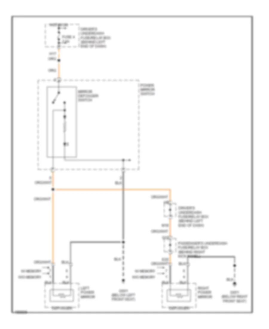
DEFOGGERS
Heated Mirrors Wiring Diagram for Acura MDX 2004
 https://portal-diagnostov.com/license.html
Automotive Electricians Portal FZCO
Automotive Electricians Portal FZCO
https://portal-diagnostov.com/license.html
https://portal-diagnostov.com/license.html
Automotive Electricians Portal FZCO
Automotive Electricians Portal FZCOList of elements for Heated Mirrors Wiring Diagram for Acura MDX 2004:
- Defogger
- Driver's underdash fuse/relay box (behind left end of dash)
- Fuse 4 7.5a
- G12
- G601 (below left front seat)
- G651 (below right front seat)
- H17
- Hot in on
- Left power mirror
- M18
- Mirror defogger switch
- Passenger's underdash fuse/relay box (behind right kick panel)
- Power mirror switch
- Right power mirror
- W/ memory
- W/o memory
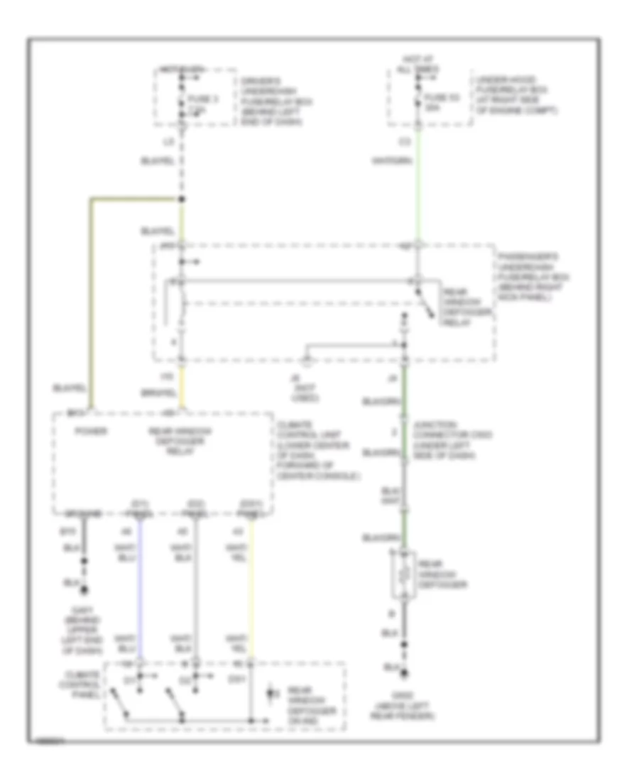
Rear Defogger Wiring Diagram for Acura MDX 2004
 https://portal-diagnostov.com/license.html
Automotive Electricians Portal FZCO
Automotive Electricians Portal FZCO
https://portal-diagnostov.com/license.html
https://portal-diagnostov.com/license.html
Automotive Electricians Portal FZCO
Automotive Electricians Portal FZCOList of elements for Rear Defogger Wiring Diagram for Acura MDX 2004:
- (d1) panel
- (d2) panel
- (ds1) panel
- (not used)
- B13
- B15
- Climate control panel
- Climate control unit (lower center of dash, forward of center console)
- Driver's underdash fuse/relay box (behind left end of dash)
- Ds1
- Fuse 3 7.5a
- Fuse 53 30a
- G401 (behind upper left end of dash)
- G602 (above left rear fender)
- Ground
- Hot at all times
- Hot in on
- I15
- J15
- Junction connector c503 (under left side of dash)
- Passenger's underdash fuse/relay box (behind right kick panel)
- Power
- Rear window defogger
- Rear window defogger on ind
- Rear window defogger relay
- Under-hood fuse/relay box (at right side of engine compt)
ENGINE PERFORMANCE
3.5L
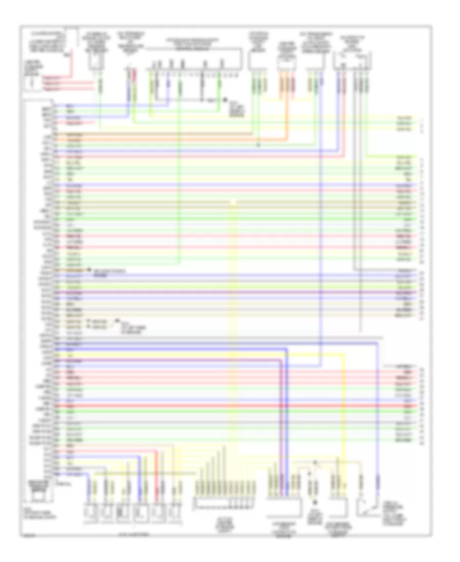
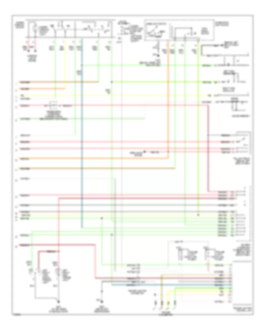
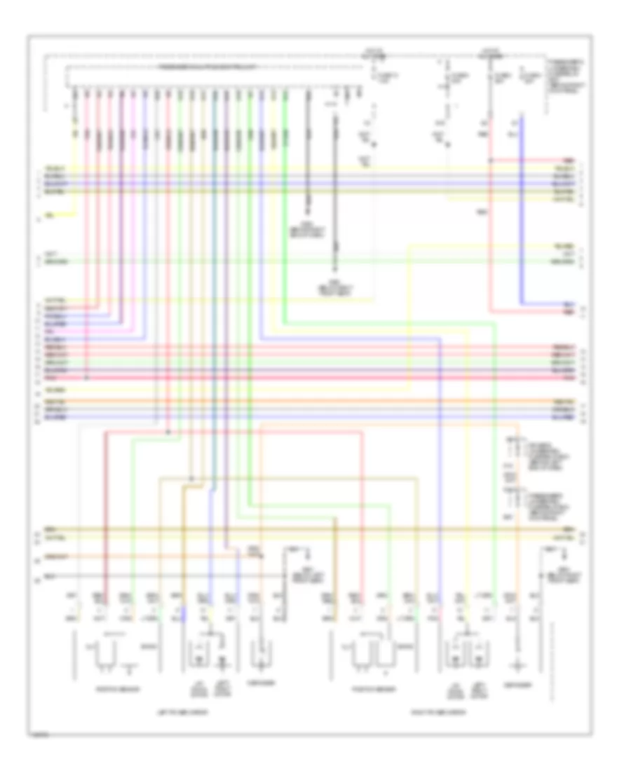
3.5L, Engine Performance Wiring Diagram (1 of 5) for Acura MDX 2004
 https://portal-diagnostov.com/license.html
Automotive Electricians Portal FZCO
Automotive Electricians Portal FZCO
https://portal-diagnostov.com/license.html
https://portal-diagnostov.com/license.html
Automotive Electricians Portal FZCO
Automotive Electricians Portal FZCOList of elements for 3.5L, Engine Performance Wiring Diagram (1 of 5) for Acura MDX 2004:
- (at middle of engine compt) map sensor
- (at middle of engine compt) throttle actuator control module
- (at rear of engine, on top of water passage) ect sensor
- (center of engine compt) j/c c104
- (on front of engine) imrc actuator
- (on transaxle end cover) atf temperature sensor
- (on transmission housing) output shaft (countershaft) speed sensor
- A (partial)
- Afshtc b1
- Afshtc b2
- Air conditioning system
- Altc
- Altf
- B22
- Barometer pressure sensor
- Ckp sensor (a & b) (on front of engine)
- Ckpa
- Ckpb
- Climate control unit (lower center of dash, forward of center console)
- Cmp
- Cmp sensor (on right side of engine compt)
- Ect
- Egr
- Egrp
- Fuel injectors
- G101 (at left rear of engine)
- Gnd
- Iat2
- Igls1
- Igls2
- Igls3
- Igls4
- Igls5
- Igls6
- Igp
- Imrc+
- Imrc-
- Imrcm
- Inj1
- Inj2
- Inj3
- Inj4
- Inj5
- Inj6
- Ipb1
- Ipb2
- J/c c103 (center of engine compt)
- Lg1
- Lg2
- Map
- Minh
- Minhi
- Op3sw
- Op4sw
- Pcm (on right side of engine compt)
- Pcs
- Pdsw
- Pnk
- Red
- Rly
- Sedf
- Sefd
- Sg1
- Sg2
- Sha
- Shb
- Shc
- Sho2s b1
- Sho2s b2
- So2shtc b2
- Tatf
- Vbsol
- Vbu
- Vcc1
- Vcc2
- Vcentb1
- Vcentb2
- Vlblb1
- Vlblb2
- Vsb1
- Vsb2
- Vtec oil pressure switch (on lower right front of engine)
- Vtpsw
- Vts
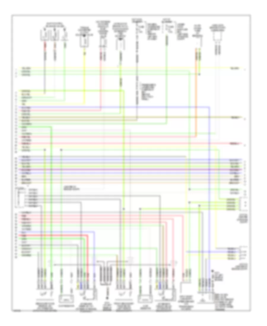
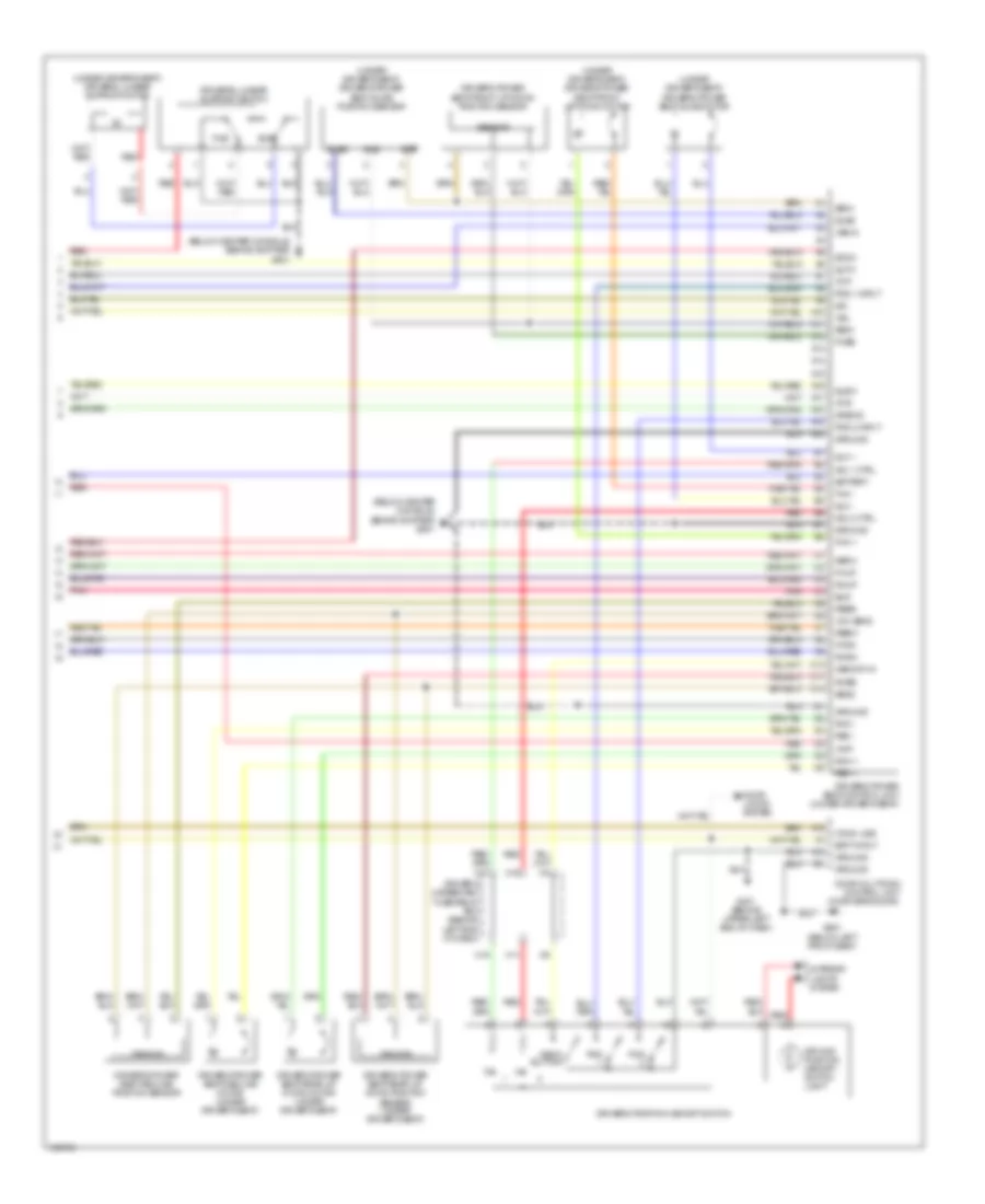
3.5L, Engine Performance Wiring Diagram (2 of 5) for Acura MDX 2004
 https://portal-diagnostov.com/license.html
Automotive Electricians Portal FZCO
Automotive Electricians Portal FZCO
https://portal-diagnostov.com/license.html
https://portal-diagnostov.com/license.html
Automotive Electricians Portal FZCO
Automotive Electricians Portal FZCOList of elements for 3.5L, Engine Performance Wiring Diagram (2 of 5) for Acura MDX 2004:
- (at front of engine, on oil pump housing extension) vtec solenoid valve
- (center of engine compt)
- (in air intake tube) iat sensor 2
- (middle of engine compt) alternator
- (on top rear of intake manifold) evap canister purge valve
- A/f sensor (front) (b2, s1) (at middle of engine compt)
- A/f sensor (rear) (b1, s1) (at rear of engine, in exhaust)
- B10
- Braided wire
- Chip resistor
- Driver's underdash fuse/relay box (behind left end of dash)
- Egr valve & egr valve position sensor (at rear of left cylinder head, on top of water passage)
- Front secondary ho2s (b2, s2) (left side of engine compt)
- Fuse 15a
- Fuse 7.5a
- G101 (at left rear of engine)
- H12
- Hot at all times
- Hot in on or start
- Input shaft (mainshaft) speed sensor (on transmission housing)
- J/c c103 (center of engine compt)
- J/c c104
- J/c c104 (center of engine compt)
- J12
- Passenger's underdash fuse/relay box (behind right kick panel)
- Red
- Secondary ho2s (rear b1, s2) (on three way catalytic converter)
- Shift control solenoid valves
- Torque converter clutch solenoid valve
- Under- hood sub-fuse box (left side of engine compt)
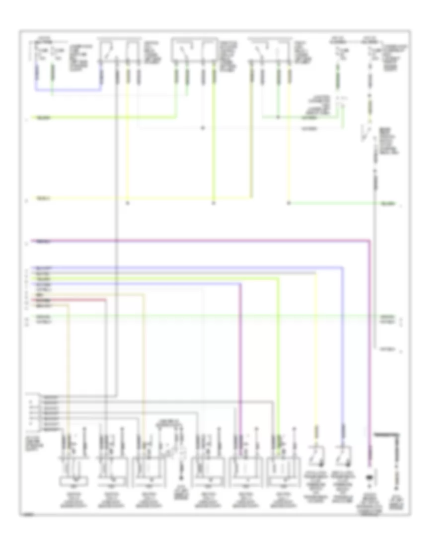
3.5L, Engine Performance Wiring Diagram (3 of 5) for Acura MDX 2004
 https://portal-diagnostov.com/license.html
Automotive Electricians Portal FZCO
Automotive Electricians Portal FZCO
https://portal-diagnostov.com/license.html
https://portal-diagnostov.com/license.html
Automotive Electricians Portal FZCO
Automotive Electricians Portal FZCOList of elements for 3.5L, Engine Performance Wiring Diagram (3 of 5) for Acura MDX 2004:
- (center of engine compt)
- 3rd clutch transmission fluid pressure switch (on transaxle end cover)
- 4th clutch transmission fluid pressure switch (on transmission housing)
- A17
- Braided wire
- Brake pedal position switch (at top of brake pedal arm)
- Fuse 15a
- Fuse 20a
- G101 (at left rear of engine)
- Hot at all times
- Icm
- Ignition coil 1 (middle of engine compt)
- Ignition coil 2 (middle of engine compt)
- Ignition coil 3 (middle of engine compt)
- Ignition coil 4 (middle of engine compt)
- Ignition coil 5 (middle of engine compt)
- Ignition coil 6 (middle of engine compt)
- Ignition coil relay (under left side of dash)
- J/c c103 (center of engine compt)
- J/c c104
- Junction connector c404 (under left side of dash)
- Knock sensor (on top of engine block, under intake manifold)
- Pgm-fi main relay 1 (under left side of dash)
- Throttle actuator control module relay (under left side of dash)
- Under-hood fuse sub-fuse box (left side of engine compt)
- Under-hood fuse/relay box (at right side of engine compt)
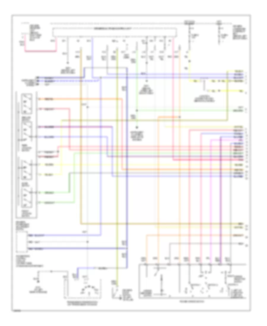
3.5L, Engine Performance Wiring Diagram (4 of 5) for Acura MDX 2004
 https://portal-diagnostov.com/license.html
Automotive Electricians Portal FZCO
Automotive Electricians Portal FZCO
https://portal-diagnostov.com/license.html
https://portal-diagnostov.com/license.html
Automotive Electricians Portal FZCO
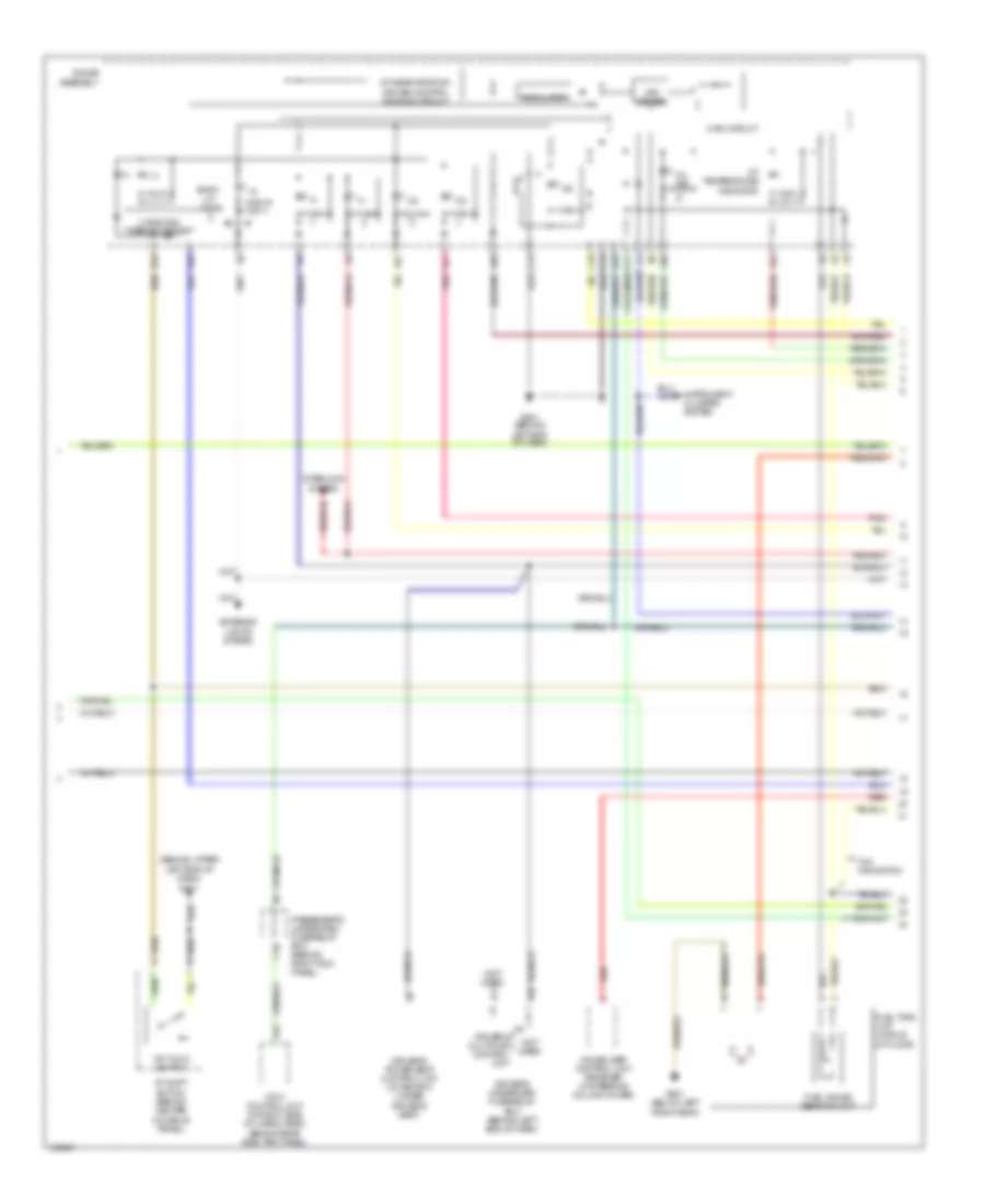
Automotive Electricians Portal FZCOList of elements for 3.5L, Engine Performance Wiring Diagram (4 of 5) for Acura MDX 2004:
- (behind upper left end of dash) g401
- (not used)
- 1st hold switch
- 2 position cancel circuit
- A/t gear position/ cruise control dimming circuit
- A/t shift switch (behind center console panel)
- A/t temperature indicator
- A10
- A11
- A12
- A13
- A24
- A27
- A28
- A3 driver's multiplex control unit
- A30
- Back- up lights
- C10
- C12
- C13
- D17
- Driver's power seat control unit (w/ memory) (under
- Driver's seat)
- Driver's underdash fuse/relay box (behind left end of dash)
- Exterior lights system
- Fuel gauge sending unit
- Fuel tank unit (middle of floor)
- G501 (behind left end of dash)
- G601 (below left front seat)
- Gauge assembly
- Immobilizer control unit receiver (in steering column cover)
- Instrument cluster system
- Interlock system
- K10
- Led driver
- Main circuit
- Mil ind
- Passenger's underdash fuse/relay box (behind right kick panel)
- Pnk
- Red
- Regulator
- Vtm-4 control unit (at right side of cargo area, behind rear side trim panel)
- W/o navigation
3.5L, Engine Performance Wiring Diagram (5 of 5) for Acura MDX 2004
 https://portal-diagnostov.com/license.html
Automotive Electricians Portal FZCO
Automotive Electricians Portal FZCO
https://portal-diagnostov.com/license.html
https://portal-diagnostov.com/license.html
Automotive Electricians Portal FZCO
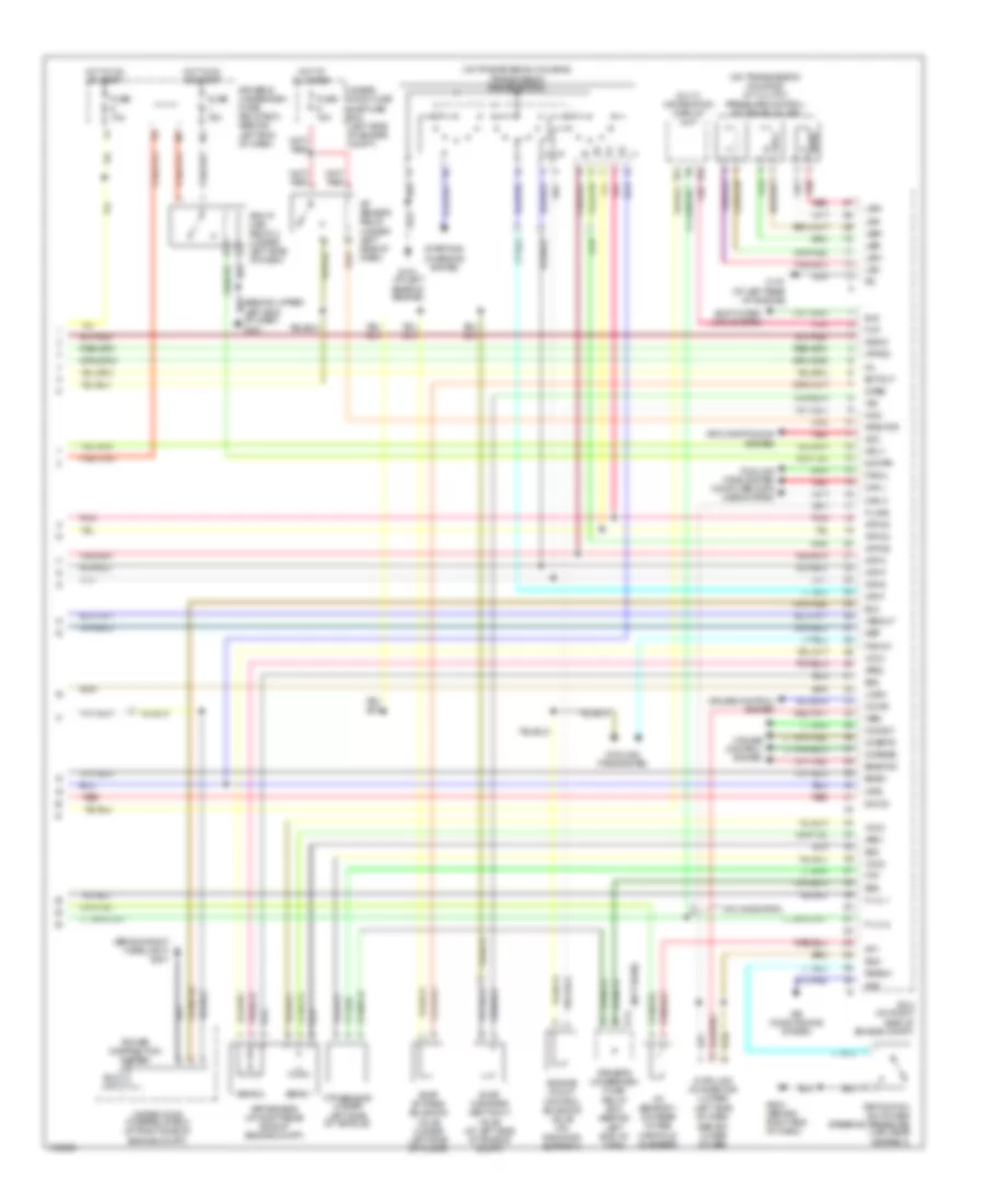
Automotive Electricians Portal FZCOList of elements for 3.5L, Engine Performance Wiring Diagram (5 of 5) for Acura MDX 2004:
- (behind right headlight) g201
- (not used)
- (on transmission housing) a/t clutch pressure control solenoid valves
- (on transmission housing) transmission range switch
- 2wbs
- A/f sensor relay (under left side of dash)
- Acc
- Acs
- Afshtcr
- Air conditioning system
- App sensor (at right rear side of engine compt)
- Aps1
- Aps2
- Atfind
- Atp d3
- Atp d4
- Atp d5
- Atp f
- Atp n
- Atp p
- Atp r
- Atp2
- B14
- B19
- Bksw
- Bkswnc
- Can h
- Can l
- Ccind
- Ccmsw
- Ccress
- Ccsets
- Cooling fans system
- Cooling fans system computer data lines system
- Cruise control system
- D14
- D5ind
- Data link connector (lower left side of dash, behind lower cover)
- Driver's underdash fuse/ relay box (behind left end of dash)
- Ectout
- Eld
- Eld unit
- Engine mount control solenoid valve (on radiator support)
- Evap by-pass solenoid valve (under left side of floor)
- Evap canister vent shut valve (at left side of engine compt)
- F-lvl 1
- F-lvl 2
- Fan ch
- Fancl
- Ftp
- Ftp sensor (under left side of vehicle)
- Fup
- Fuse 10a
- Fuse 15a
- G101 (at left rear of engine)
- G503 (behind right end of dash)
- Hot at all times
- Hot in on or start
- Iat sensor 1 (on rear intake manifold chamber)
- Iat1
- Imocd
- Imofpr
- K-line
- Left end of dash) g401
- Lhsw
- Lsa+
- Lsa-
- Lsb+
- Lsb-
- Lsc+
- Lsc-
- Mcs
- Mil
- Mrly
- Multi- information display unit
- Nep
- Pcm (on right side of engine compt)
- Pgm-fi main relay 2 (under left side of dash)
- Pnk
- Power distribution system
- Psp switch (on power steering pressure line, near gearbox)
- Pspsw
- Red
- Scs
- Sens 1
- Sens 2
- Sg2
- Sg3
- Sg5
- Shift inter- lock system
- Sls
- Starting/ charging system
- Under- hood fuse sub-fuse box (left side of engine compt)
- Under-hood fuse/relay box (at right side of engine compt)
- Vcc3
- Vcc4
- Vcc5
- Vssout
- Vsv
- W/o navigation
- Wen
EXTERIOR LIGHTS
Backup Lamps Wiring Diagram for Acura MDX 2004
 https://portal-diagnostov.com/license.html
Automotive Electricians Portal FZCO
Automotive Electricians Portal FZCO
https://portal-diagnostov.com/license.html
https://portal-diagnostov.com/license.html
Automotive Electricians Portal FZCO
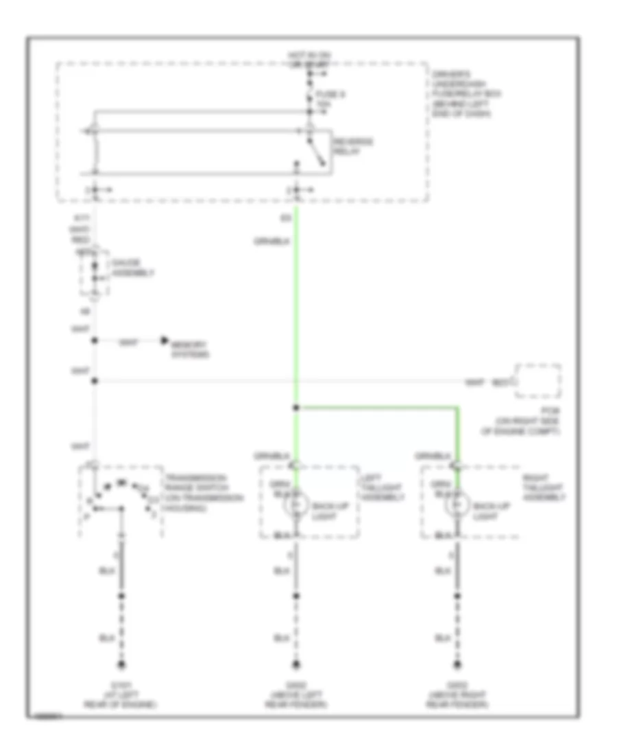
Automotive Electricians Portal FZCOList of elements for Backup Lamps Wiring Diagram for Acura MDX 2004:
- A22
- B23
- Back-up light
- Driver's underdash fuse/relay box (behind left end of dash)
- Fuse 9 10a
- G101 (at left rear of engine)
- G602 (above left rear fender)
- G652 (above right rear fender)
- Gauge assembly
- Hot in on or start
- K11
- Left taillight assembly
- Memory systems
- Pcm (on right side of engine compt)
- Reverse relay
- Right taillight assembly
- Transmission range switch (on transmission housing)
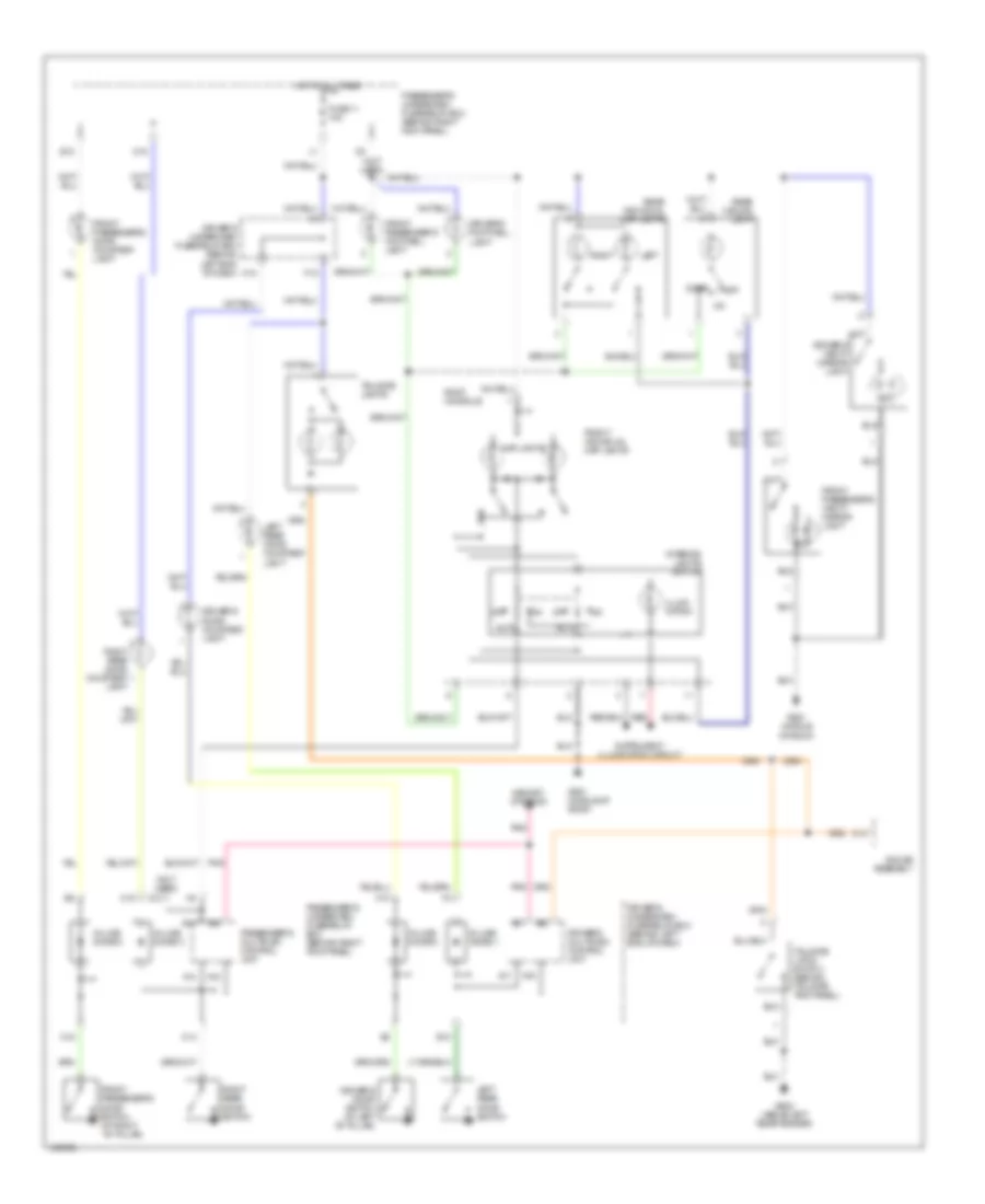
Exterior Lamps Wiring Diagram (1 of 2) for Acura MDX 2004
 https://portal-diagnostov.com/license.html
Automotive Electricians Portal FZCO
Automotive Electricians Portal FZCO
https://portal-diagnostov.com/license.html
https://portal-diagnostov.com/license.html
Automotive Electricians Portal FZCO
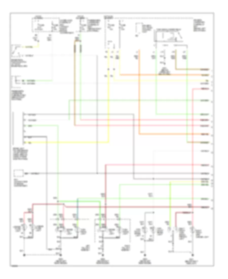
Automotive Electricians Portal FZCOList of elements for Exterior Lamps Wiring Diagram (1 of 2) for Acura MDX 2004:
- A22
- B39
- Brake light failure sensor (at left side of cargo area, on inside of rear side trim panel)
- Brake pedal position switch (at top of brake pedal arm)
- Brake/ tail- light
- Driver's multiplex control unit
- Driver's underdash fuse/relay box (behind left end of dash)
- Fuse 10a
- Fuse 15a
- Fuse 20a
- Fuse 7.5a
- G201 (behind right headlight)
- G401 (behind upper left end of dash)
- G602 (above left rear fender)
- G652 (above right rear fender)
- H15
- High mount brake light
- Hot at all times
- Hot in on or start
- J16
- L15
- L21
- Left taillight assembly
- License plate light
- Passenger's underdash fuse/relay box (behind right kick panel)
- Pcm (on right side of engine compartment)
- Right front side marker light
- Right front turn signal/ parking light
- Right taillight assembly
- Turn signal light
- Turn signal/hazard relay
- Under-hood fuse/relay box (at right side of engine compartment)
Exterior Lamps Wiring Diagram (2 of 2) for Acura MDX 2004
 https://portal-diagnostov.com/license.html
Automotive Electricians Portal FZCO
Automotive Electricians Portal FZCO
https://portal-diagnostov.com/license.html
https://portal-diagnostov.com/license.html
Automotive Electricians Portal FZCO
Automotive Electricians Portal FZCOList of elements for Exterior Lamps Wiring Diagram (2 of 2) for Acura MDX 2004:
- (behind left end of dash) g501
- 7.5a
- Auto
- B17
- Brake lamp ind
- C10
- C13
- Combination light switch
- D18
- Driver's underdash fuse/relay box (behind left end of dash)
- Fuse 15a
- G301 (at left rear of engine compt)
- G401 (behind upper left end of dash)
- G602 (above left rear fender)
- Gauge assembly
- Hazard warning switch
- Hazard warning switch light
- Head
- Headlight switch
- Headlights system
- Hot at all times
- Interior lights system
- L17
- Left front side marker light
- Left front turn signal/ parking light
- Left turn signal ind
- M20
- Off
- Park
- Passenger's underdash fuse/relay box (behind right kick panel)
- Red
- Right turn signal ind
- Taillight relay (behind left side of dash)
- Trailer connector
- Trailer light in-line fuse 1
- Trailer light in-line fuse 2
- Trailer lighting connector
- Trailer lighting control unit
- Turn signal switch
- Under- hood fuse sub-fuse box (left side of engine compt)
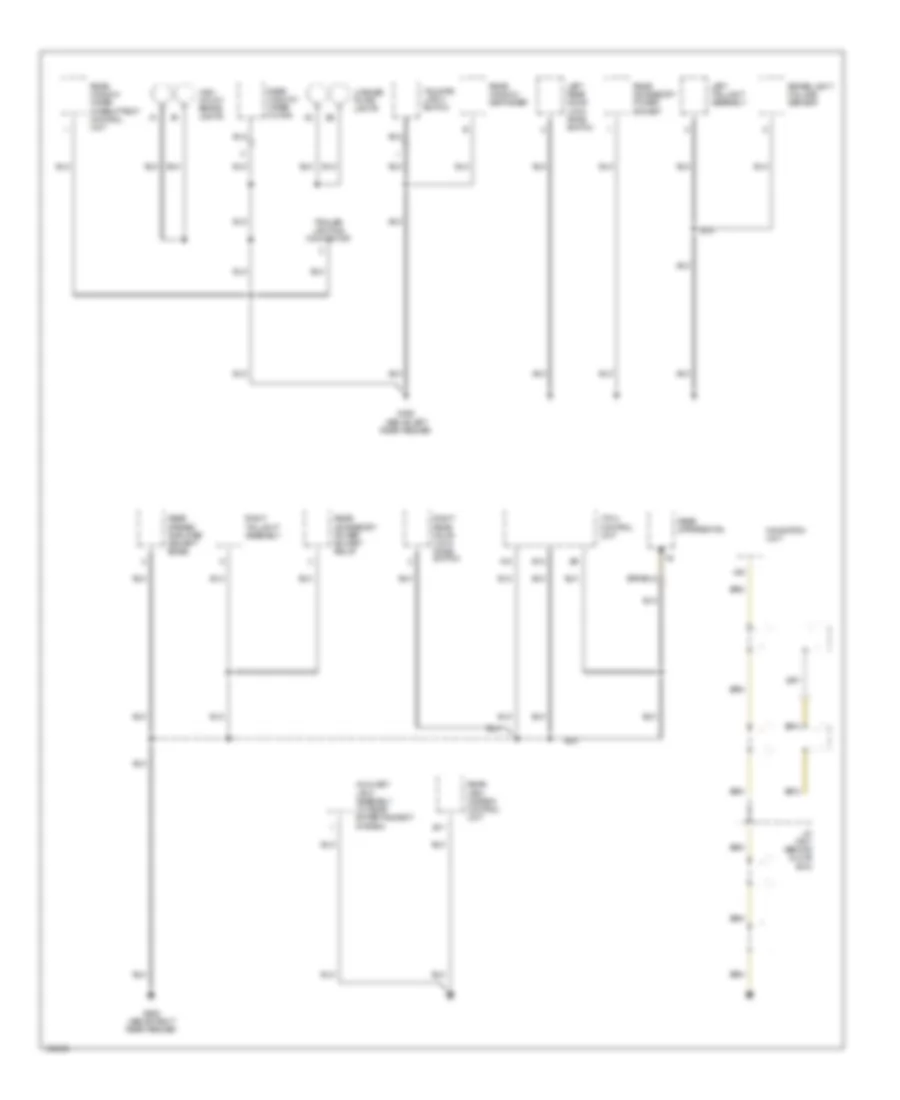
GROUND DISTRIBUTION
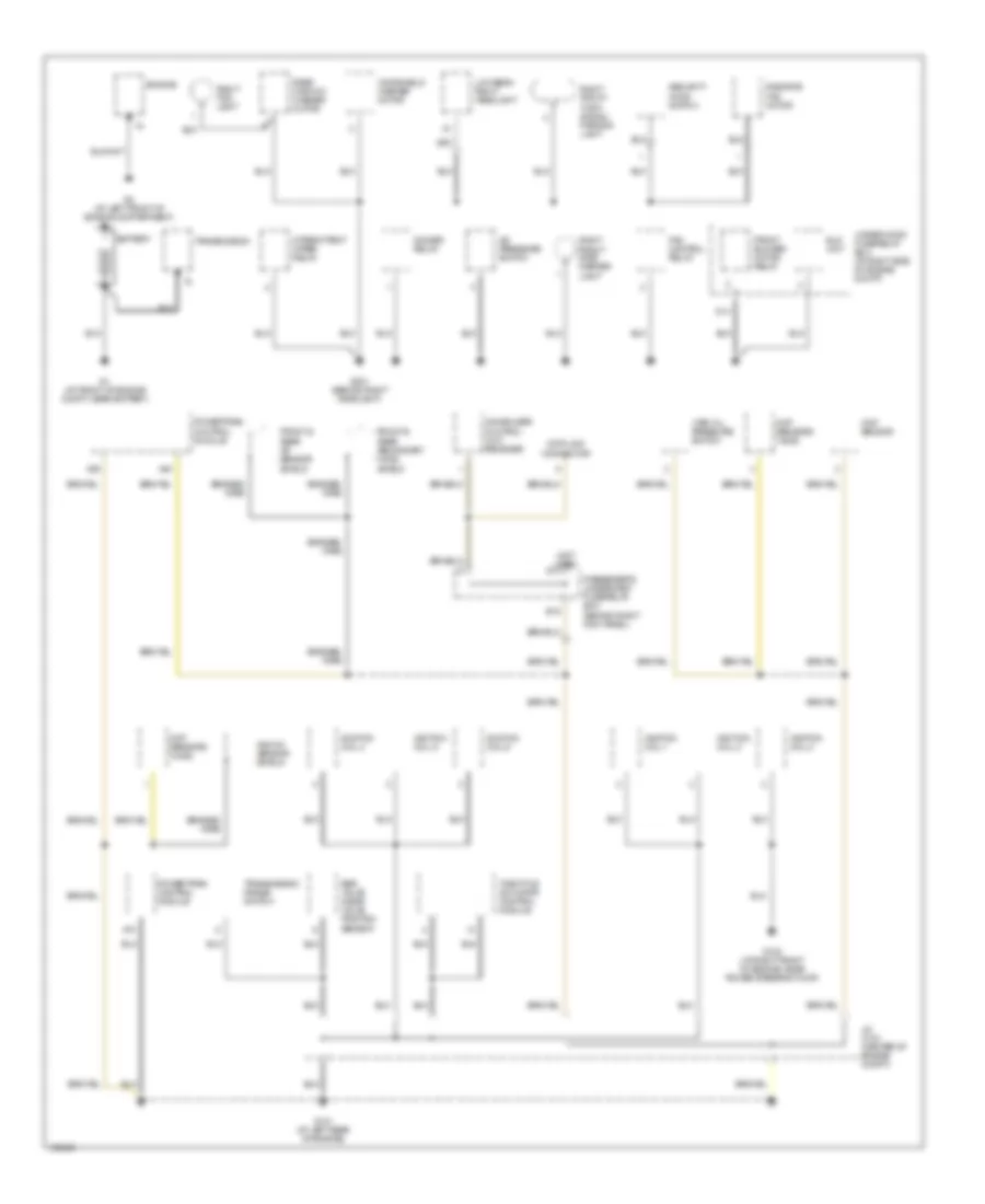
Ground Distribution Wiring Diagram (1 of 4) for Acura MDX 2004
 https://portal-diagnostov.com/license.html
Automotive Electricians Portal FZCO
Automotive Electricians Portal FZCO
https://portal-diagnostov.com/license.html
https://portal-diagnostov.com/license.html
Automotive Electricians Portal FZCO
Automotive Electricians Portal FZCOList of elements for Ground Distribution Wiring Diagram (1 of 4) for Acura MDX 2004:
- (not used) g14
- A/c pressure switch
- A39
- A40
- A73
- B18
- Battery
- Braided wire
- Ckp sensors (a & b)
- Cmp sensor
- D14
- Data link connector
- Dimmer relay
- Egr valve & egr valve position sensor
- Eld unit
- Engine
- Fan control relay
- Front & rear a/f sensor shield
- Front & rear secondary ho2s shield
- Front blower motor relay
- G1 (at front of engine compt, near battery)
- G101 (at left rear of engine)
- G102 (at right front of engine, near power steering pump)
- G2 (at left front of engine compartment)
- G201 (behind right headlight)
- Ignition coil 1
- Ignition coil 2
- Ignition coil 3
- Ignition coil 4
- Ignition coil 5
- Ignition coil 6
- Immobilizer control unit receiver
- Intermittent wiper relay
- J/c c104 (center of engine compt)
- Knock sensor shield
- Low beam right headlight
- Passenger's underdash fuse/relay box (behind right kick panel)
- Powertrain control module
- Radiator fan motor
- Rear window washer motor
- Right fog light
- Right front side marker light
- Right front turn signal/ parking light
- Security hood switch
- Throttle actuator control module
- Transmission
- Transmission range switch
- Under-hood fuse/relay box (at right side of engine compt)
- Vtec oil pressure switch
- Windshield washer motor
Ground Distribution Wiring Diagram (2 of 4) for Acura MDX 2004
 https://portal-diagnostov.com/license.html
Automotive Electricians Portal FZCO
Automotive Electricians Portal FZCO
https://portal-diagnostov.com/license.html
https://portal-diagnostov.com/license.html
Automotive Electricians Portal FZCO
Automotive Electricians Portal FZCOList of elements for Ground Distribution Wiring Diagram (2 of 4) for Acura MDX 2004:
- (not used) cigarette lighter connector
- A14
- A20
- Audio unit
- Automatic dimming inside mirror
- B10
- B11
- B22
- C12
- C13
- Console accessory power socket
- Driver's lumbar support switch (w/ memory)
- Driver's multiplex control unit
- Driver's power seat adjustment switch (w/o memory)
- Driver's power seat control unit (w/ memory)
- Driver's seat back heater
- Driver's seat belt switch
- Driver's seat heater switch
- Driver's underdash fuse/relay box (behind left end of dash)
- Driver's vanity mirror light
- Dvd player unit
- Electrical compass unit (w/o navigation)
- Front accessory power socket
- Front individual map lights
- Front passenger's power seat adjustment switch (w/ memory)
- Front passenger's seat belt switch
- Front passenger's seat cushion heater
- Front passenger's seat heater switch
- Front passenger's vanity mirror light
- Front passenger's weight sensor unit
- G501 (behind left end of dash)
- G502 (behind right center of dash)
- G503 (behind right end of dash)
- G551 (middle of roof)
- G631 (below center console, behind shifter)
- Gauge assembly
- Glove box light
- Home link
- Interior lights switch
- Keyless buzzer
- Keyless receiver unit
- Moonroof switch
- Multi- information display unit (w/o navigation)
- Navigation display unit
- Navigation unit
- Opds unit
- Passenger's multiplex control unit
- Passenger's underdash fuse/relay box (behind right kick panel)
- Psp switch
- Rain sensor & automatic wiper control unit (w/ auto wiper)
- Rear blower motor relay
- Rear blower power transistor
- Rear controller & screen (w/ rear entertainment system)
- Rear heater- a/c control panel unit
- Roof console
- Stereo amplifier (bose)
- Trip meter select/ reset switch
- W/ navigation
- W/ rear entertainment system
- Washer fluid level switch
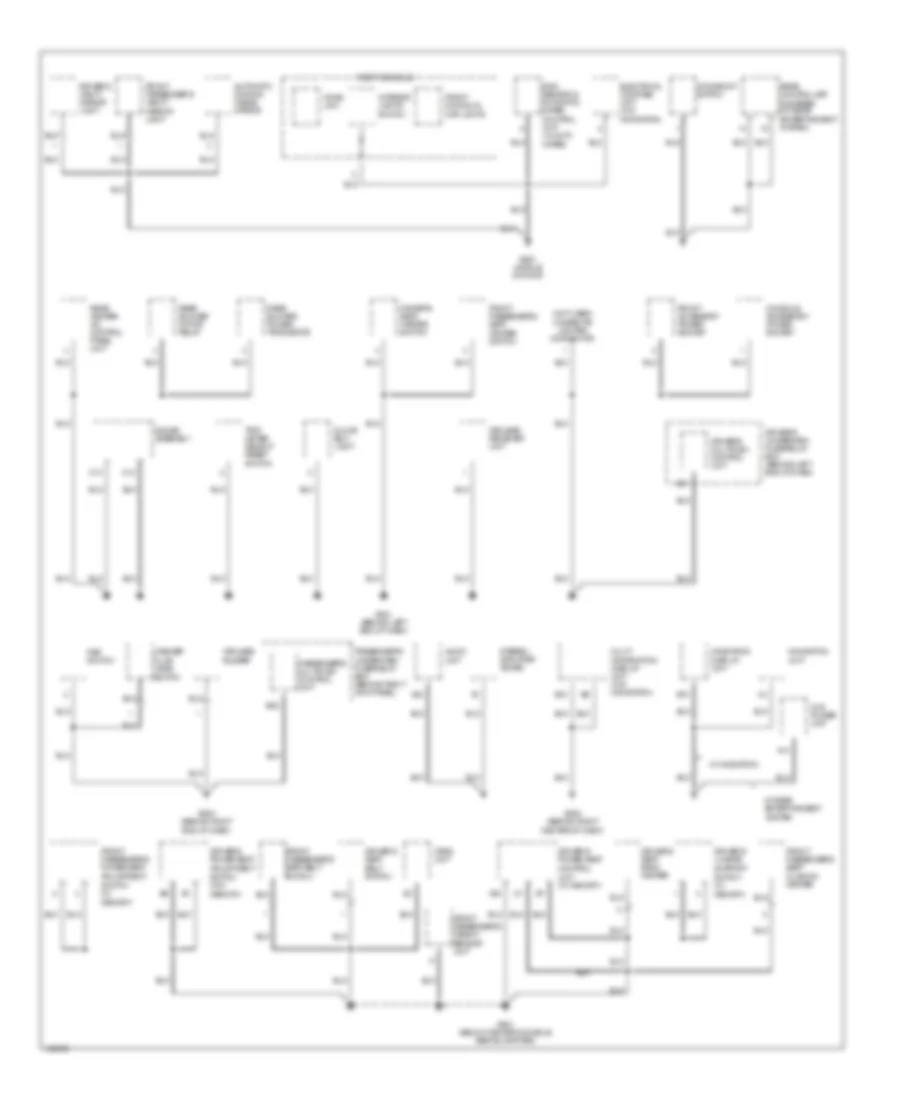
Ground Distribution Wiring Diagram (3 of 4) for Acura MDX 2004
 https://portal-diagnostov.com/license.html
Automotive Electricians Portal FZCO
Automotive Electricians Portal FZCO
https://portal-diagnostov.com/license.html
https://portal-diagnostov.com/license.html
Automotive Electricians Portal FZCO
Automotive Electricians Portal FZCOList of elements for Ground Distribution Wiring Diagram (3 of 4) for Acura MDX 2004:
- (not used)
- A/t shift switch
- A12
- A14
- A22
- A23
- Accessory power socket relay
- Automatic lighting control unit
- B15
- Brake fluid level switch
- Climate control unit
- Combination light switch
- Cruise control master switch
- Data link connector
- Door multiplex control unit
- Dpms switch (w/ memory)
- Driver's door key cylinder switch
- Driver's door lock knob switch
- Driver's door lock switch
- Driver's multiplex control unit
- Driver's underdash fuse/relay box (behind left end of dash)
- Driver's underdash fuse/relay box box (behind left end of dash)
- Drl control unit (canada)
- F10
- Front blower power transistor
- Front passenger's door lock knob switch
- Front passenger's door lock switch
- Fuel tank unit
- G301 (at left rear of engine compt)
- G302 (left side of engine compt)
- G401 (behind upper left end of dash)
- G601 (below left front seat)
- G651 (below right front seat)
- G801 (under center of dash)
- H16
- Ignition key switch
- Ignition key switch/ key light
- L15
- Left fog light
- Left front side marker light
- Left front turn signal/ parking light
- Left power mirror
- Low beam left headlight
- Low hold switch
- Mes connector
- Moonroof close relay
- Moonroof open relay
- Multiplex control inspection connector
- Park pin switch
- Passenger's multiplex control unit
- Passenger's underdash fuse/relay box (behind right kick panel)
- Pgm-fi main relay 2
- Power mirror switch
- Power window control unit
- Power window relay
- Right power mirror
- Seat heater relay
- Shift lock relay
- Srs unit
- Tpms receiver unit
- Turn signal/ hazard relay
- Vsa modulator control unit
- W/ auto wiper
- W/o memory w/ memory
- Windshield wiper motor
- Wiper/ washer switch
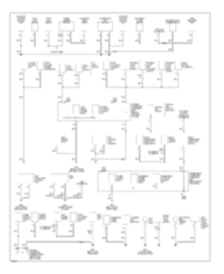
Ground Distribution Wiring Diagram (4 of 4) for Acura MDX 2004
 https://portal-diagnostov.com/license.html
Automotive Electricians Portal FZCO
Automotive Electricians Portal FZCO
https://portal-diagnostov.com/license.html
https://portal-diagnostov.com/license.html
Automotive Electricians Portal FZCO
Automotive Electricians Portal FZCOList of elements for Ground Distribution Wiring Diagram (4 of 4) for Acura MDX 2004:
- A10
- A19
- Auxiliary jack assembly (w/ rear entertainment system)
- B11
- B12
- Brake light failure sensor
- G602 (above left rear fender)
- G652 (above right rear fender)
- High mount brake lights
- J/c c501 (behind glove box)
- Left rear door lock knob switch
- Left taillight assembly
- License plate lights
- Navigation unit
- Rear accessory power socket
- Rear accessory power socket relay
- Rear differential
- Rear stereo amplifier (except bose)
- Rear view camera control unit
- Rear window defogger
- Rear window wiper intermittent control unit
- Rear window wiper motor
- Right rear door lock knob switch
- Right taillight assembly
- Tailgate latch switch
- Trailer lighting connector
- Vtm-4 control unit
HEADLIGHTS
Headlights Wiring Diagram, with DRL (1 of 2) for Acura MDX 2004
 https://portal-diagnostov.com/license.html
Automotive Electricians Portal FZCO
Automotive Electricians Portal FZCO
https://portal-diagnostov.com/license.html
https://portal-diagnostov.com/license.html
Automotive Electricians Portal FZCO
Automotive Electricians Portal FZCOList of elements for Headlights Wiring Diagram, with DRL (1 of 2) for Acura MDX 2004:
- (in multi- relay box) dimmer relay
- (not used)
- A20
- Anti-lock brakes system
- Auto
- Automatic lighting diode (under left side of dash)
- B13
- B16
- C18
- Combination light switch
- Dimmer switch
- Driver's underdash fuse/relay box (behind left end of dash)
- Drl control unit
- Flash- to-pass switch
- Fog light relay (behind left side of dash)
- Fog light switch
- Fog light switch light
- Fuse 13 7.5a
- Fuse 4 7.5a
- Fuse 5 10a
- Fuse 6 10a
- Fuse 9 10a
- G201 (behind right headlight)
- G301 (at left rear of engine compartment)
- G401 (behind upper left end of dash)
- H13
- Head
- Headlight switch
- Hot at all times
- Hot in on
- Hot in on or start
- I12
- Interior lights system
- L14
- Left fog light
- M15
- Off
- On ind
- Park
- Parking brake switch (under left side of dash)
- Passenger's multiplex control unit
- Passenger's underdash fuse/relay box (behind right kick panel)
- Red
- Right fog light
Headlights Wiring Diagram, with DRL (2 of 2) for Acura MDX 2004
 https://portal-diagnostov.com/license.html
Automotive Electricians Portal FZCO
Automotive Electricians Portal FZCO
https://portal-diagnostov.com/license.html
https://portal-diagnostov.com/license.html
Automotive Electricians Portal FZCO
Automotive Electricians Portal FZCOList of elements for Headlights Wiring Diagram, with DRL (2 of 2) for Acura MDX 2004:
- (behind left end of dash)
- (not used)
- A1 (not used)
- A12
- A13
- A22
- Automatic lighting control unit (under middle of dash)
- Automatic lighting sensor
- B18
- Driver's door switch (at left "b" pillar)
- Driver's multiplex control unit
- Driver's underdash fuse/relay box
- Driver's underdash fuse/relay box (behind left end of dash)
- Drl ind
- Electrical load detector unit
- Fuse
- Fuse 41 120a
- Fuse 43 20a
- Fuse 45 20a
- Fuse 50 20a
- G201 (behind right headlight)
- G301 (at left rear of engine compt)
- G401 (behind upper left end of dash)
- Gauge assembly
- Headlight relay 1
- Headlight relay 2
- High
- High beam ind
- Hot at all times
- J14
- L12
- Left headlight
- Low
- Memory systems
- Right headlight
- Taillight relay (behind left side of dash)
- Under-hood fuse/relay box (at right side of engine compt)
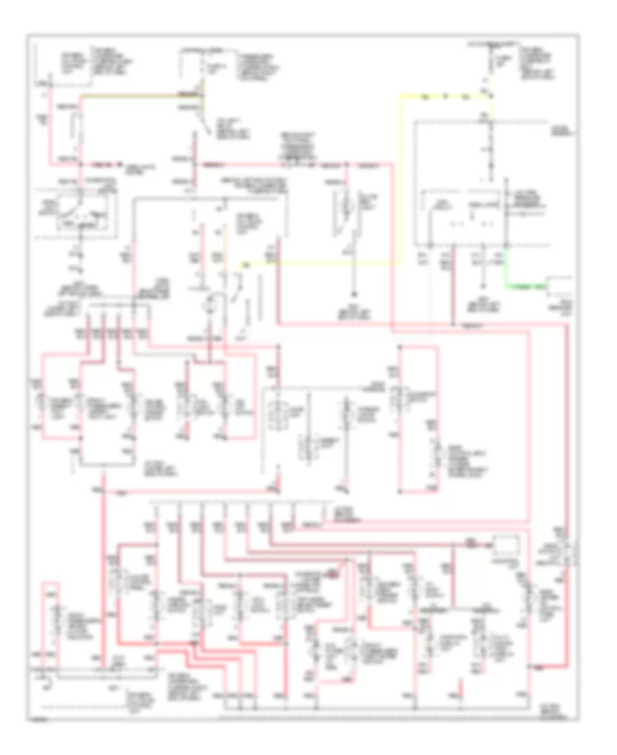
Headlights Wiring Diagram, without DRL for Acura MDX 2004
 https://portal-diagnostov.com/license.html
Automotive Electricians Portal FZCO
Automotive Electricians Portal FZCO
https://portal-diagnostov.com/license.html
https://portal-diagnostov.com/license.html
Automotive Electricians Portal FZCO
Automotive Electricians Portal FZCOList of elements for Headlights Wiring Diagram, without DRL for Acura MDX 2004:
- (behind left end of dash)
- (not used)
- A1 (not used)
- A12 (not used)
- A13
- A20
- A22
- A7 (not used)
- Auto
- Automatic lighting control unit (under middle of dash)
- Automatic lighting diode (under left side of dash)
- Automatic lighting sensor
- B13
- B16
- B18
- C18
- Combination light switch
- Dimmer relay (in multi- relay box)
- Dimmer switch
- Driver's door switch (at left "b" pillar)
- Driver's multiplex control unit
- Driver's underdash fuse/relay box
- Driver's underdash fuse/relay box (behind left end of dash)
- Electrical load detector unit
- Flash- to-pass switch
- Fog light relay (behind left side of dash)
- Fog light switch
- Fog light switch light
- Fuse 10a
- Fuse 13 7.5a
- Fuse 41 120a
- Fuse 43 20a
- Fuse 44
- Fuse 45 20a
- Fuse 50 20a
- Fuse 7.5a
- G201 (behind right headlight)
- G301 (at left rear of engine compartment)
- G301 (at left rear of engine compt)
- G401 (behind upper left end of dash)
- Gauge assembly
- H13
- Head
- Headlight relay 1
- Headlight relay 2
- Headlight switch
- High
- High beam ind
- Hot at all times
- Hot in on
- Hot in on or start
- I12
- Interior lights system
- J14
- L12
- Left fog light
- Left headlight
- Low
- M15
- Memory systems
- Off
- On ind
- Park
- Passenger's multiplex control unit
- Passenger's underdash fuse/relay box (behind right kick panel)
- Red
- Right fog light
- Right headlight
- Taillight relay (behind left side of dash)
- Under-hood fuse/relay box (at right side of engine compartment)
HORN
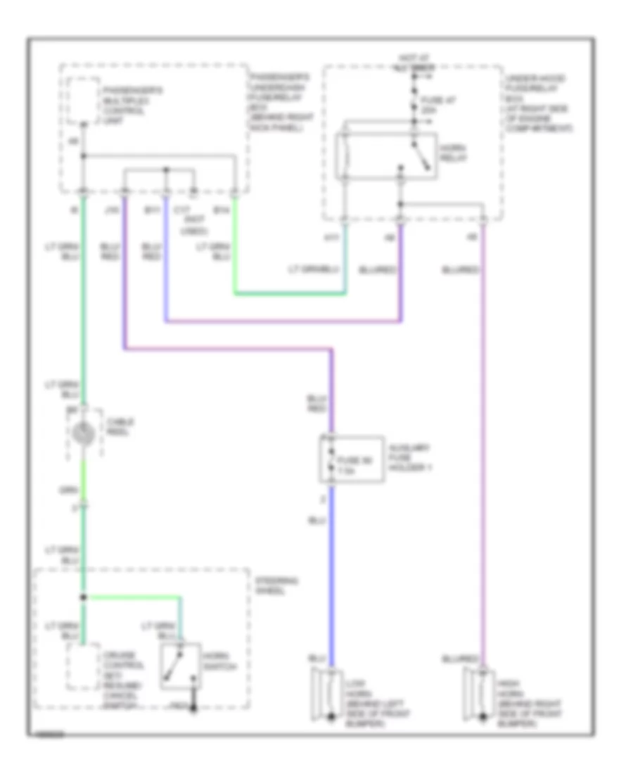
Horn Wiring Diagram for Acura MDX 2004
 https://portal-diagnostov.com/license.html
Automotive Electricians Portal FZCO
Automotive Electricians Portal FZCO
https://portal-diagnostov.com/license.html
https://portal-diagnostov.com/license.html
Automotive Electricians Portal FZCO
Automotive Electricians Portal FZCOList of elements for Horn Wiring Diagram for Acura MDX 2004:
- A11
- Auxiliary fuse holder 1
- B11
- B14
- C17 (not
- Cable reel
- Cruise control set/ resume/ cancel switch
- Fuse 47 20a
- Fuse 90 7.5a
- High horn (behind right side of front bumper)
- Horn relay
- Horn switch
- Hot at all times
- J10
- Low horn (behind left side of front bumper)
- Nca
- Passenger's multiplex control unit
- Passenger's underdash fuse/relay box (behind right kick panel)
- Steering wheel
- Under-hood fuse/relay box (at right side of engine compartment)
- Used)
INSTRUMENT CLUSTER
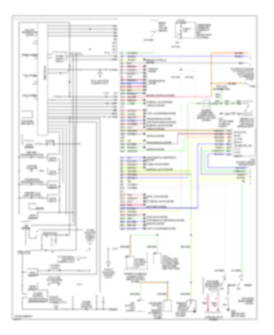
Gauges & Indicators Wiring Diagram (1 of 2) for Acura MDX 2004
 https://portal-diagnostov.com/license.html
Automotive Electricians Portal FZCO
Automotive Electricians Portal FZCO
https://portal-diagnostov.com/license.html
https://portal-diagnostov.com/license.html
Automotive Electricians Portal FZCO
Automotive Electricians Portal FZCOList of elements for Gauges & Indicators Wiring Diagram (1 of 2) for Acura MDX 2004:
- (on front of engine, at top right of oil pump housing) oil pressure switch
- A/t gear position/ cruise control dimming circuit
- A/t ind ctrl
- A10
- A11
- A12
- A13
- A14
- A15
- A16
- A17
- A18
- A19
- A20
- A21
- A22
- A23
- A24
- A25
- A26
- A27
- A28
- A29
- A30
- Anti-lock brakes system
- Anti-theft system
- B10
- B11
- B12
- B13
- B14
- B15
- B16
- B17
- B18
- B19
- B20
- B21
- B22
- B26
- B33
- B49
- B51
- Beeper
- Brake fluid level switch (left side of engine compt)
- Brake light failure sensor
- C10
- C11
- C12
- C13
- Coolant temperature gauge
- Cruise control indicator
- Cruise ctrl ind
- D5 ind
- Dial plate, f/d car frame lights
- Door locks system
- Drive circuit
- Driver's multiplex control unit
- Driver's underdash fuse/relay box (behind left end of dash)
- Drl control unit (canada)
- Ectout
- Engine controls system
- Exterior lights system
- F-lvl1
- F-lvl2
- Fuel gauge
- Fuse 13 7.5a
- G15
- G301 (at left rear of engine compt)
- G501 (behind left end of dash)
- Gauge assembly
- Headlights system
- Hot at all times
- Immobilizer control unit receiver (in steering column cover)
- Interior lights system
- K14
- Lcd back lights
- Led driver
- Lights on ind
- Low fuel indicator
- Main circuit
- Maintenance required indicator
- Mil ctrl
- Odometer/ trip display
- Off
- Parking brake switch (under left side of dash)
- Passenger's underdash fuse/relay box (behind right kick panel)
- Pcm (on right side of engine compt)
- Pnk
- Pointer
- Red
- Regulator
- Reset
- Seat belt reminder indicator
- Select
- Speedometer
- Starting/charging system
- Tachometer
- To mil indicator (diagram 2 of 2)
- To shift indicators (diagram 2 of 2)
- To turn signal indicators (diagram 2 of 2)
- To vsa indicator circuit (diagram 2 of 2)
- Transmissions system
- Trip meter select/reset switch
- Trip meter select/reset switch light
- Vssout
- Vtm-4 control unit (at right side of cargo area, behind rear side trim panel)
- Warning system
- Washer fluid level indicator
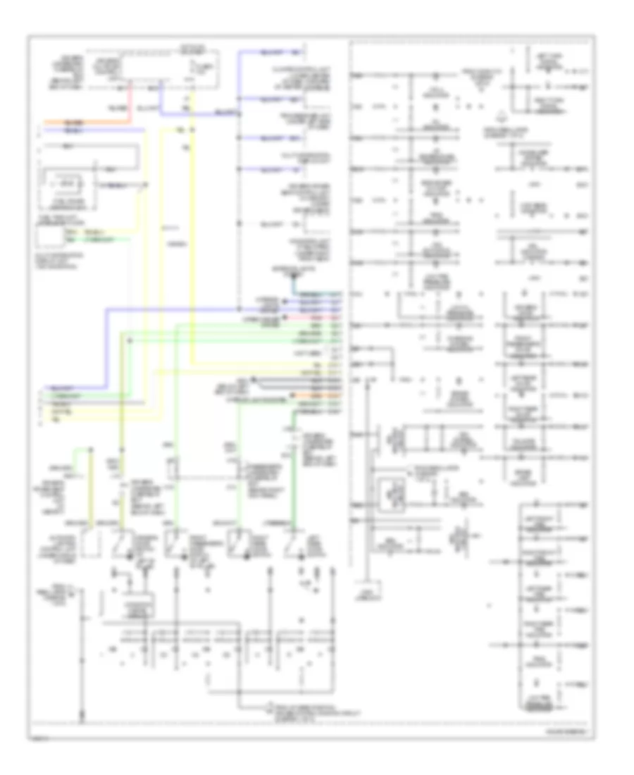
Gauges & Indicators Wiring Diagram (2 of 2) for Acura MDX 2004
 https://portal-diagnostov.com/license.html
Automotive Electricians Portal FZCO
Automotive Electricians Portal FZCO
https://portal-diagnostov.com/license.html
https://portal-diagnostov.com/license.html
Automotive Electricians Portal FZCO
Automotive Electricians Portal FZCOList of elements for Gauges & Indicators Wiring Diagram (2 of 2) for Acura MDX 2004:
- (behind left end of dash)
- (not used)
- 2 position cancel circuit
- A/t temperature indicator
- A10
- A11
- A12
- A14
- A16
- A18
- A19
- A20
- A21
- A22
- A23
- A24
- A25
- A27
- A28
- A29
- A30
- Abs indicator
- Abs indicator circuit
- Automatic lighting control unit (under middle of dash)
- B14
- B15
- B17
- B18
- B19
- B20
- B21
- B22
- Brake lamp indicator
- Brake system indicator
- C10
- C11
- C12
- C13
- C14
- C15
- C16
- Canada
- Charging system indicator
- Circuit
- Climate control unit (lower center of dash, forward of center console)
- Driver's door indicator
- Driver's door switch (at left "b" pillar)
- Driver's multiplex control unit
- Driver's power seat control unit (w/ memory)
- Driver's power seat control unit (w/ memory) (under driver's seat)
- Driver's underdash fuse/relay box
- Driver's underdash fuse/relay box (behind left end of dash)
- Drl indicator (canada)
- E10
- Exterior lights system
- From a/t gear position/ cruise control dimming circuit (diagram 1 of 2)
- From conn c10 (diagram 1 of 2)
- From regulator (diagram 1 of 2)
- From regulator e (diagram 1 of 2)
- Front passenger's door indicator
- Front passenger's door switch (at left "b" pillar)
- Fuel gauge sending unit
- Fuel tank unit (middle of floor)
- Fuse 9 10a
- G501 (below left end of dash)
- Gauge assembly
- H16
- High beam indicator
- Hot in on or start
- Immobilizer system indicator
- Indicator vsa
- Interior lights system
- J14
- J15
- Left front tire indicator
- Left rear door indicator
- Left rear door switch
- Left rear tire indicator
- Left turn signal indicator
- Low oil pressure indicator
- Low tire pressure indicator
- Main circuit
- Mil indicator
- Multi-information display unit
- Multi-information display unit (w/o navigation)
- Navigation unit (if equipped) (under right front seat)
- Passenger's underdash fuse/relay box (behind right kick panel)
- Pnk
- Right front tire indicator
- Right rear door indicator
- Right rear door switch
- Right rear tire indicator
- Right turn signal indicator
- Side air bag cut-off indicator
- Srs indicator
- Srs indicator circuit
- Tailgate indicator
- Tpms indicator
- Tpms receiver unit (under left side of dash)
- Vsa activation indicator
- Vsa system indicator
- Vtm-4 indicator
- Wiper/washer system
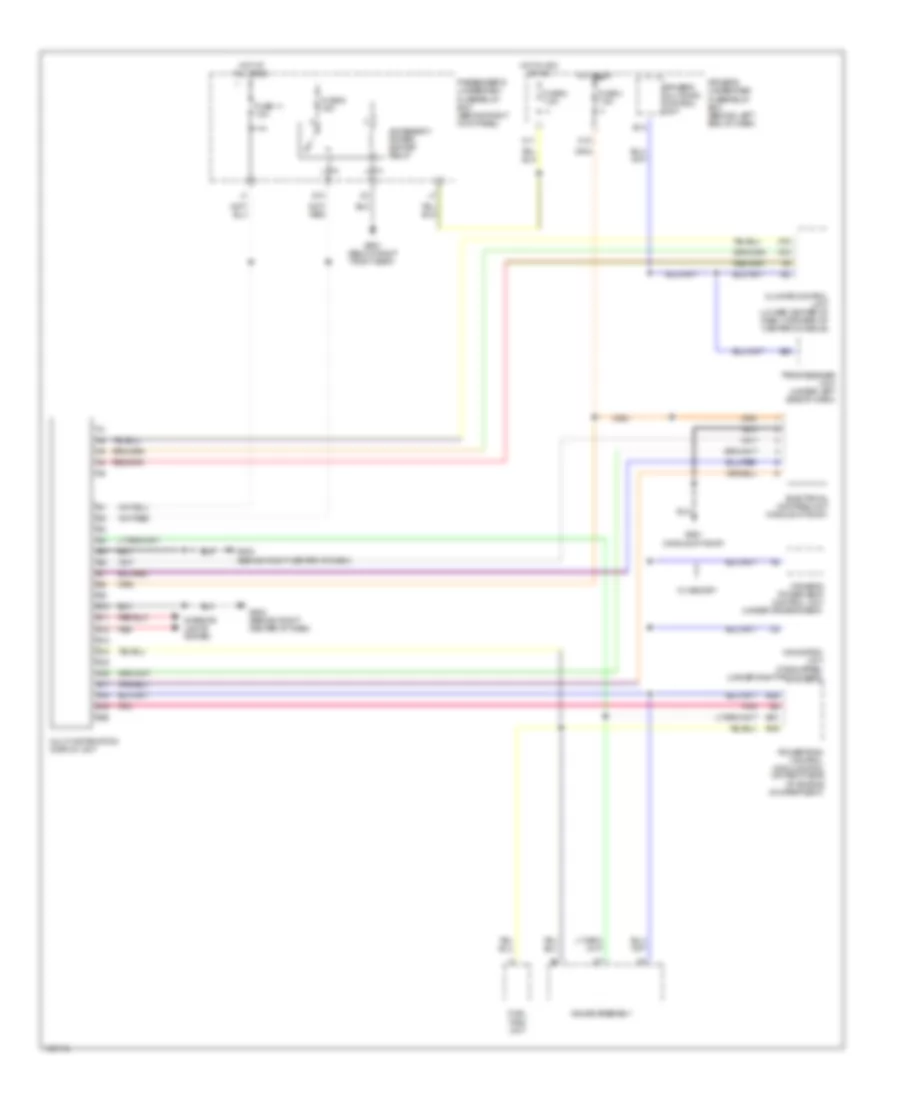
Multi-Information System Wiring Diagram for Acura MDX 2004
 https://portal-diagnostov.com/license.html
Automotive Electricians Portal FZCO
Automotive Electricians Portal FZCO
https://portal-diagnostov.com/license.html
https://portal-diagnostov.com/license.html
Automotive Electricians Portal FZCO
Automotive Electricians Portal FZCOList of elements for Multi-Information System Wiring Diagram for Acura MDX 2004:
- A15
- A16
- Accessory power socket relay
- B10
- B11
- B12
- B13
- B14
- B15
- B16
- B17
- B18
- B19
- B20
- B26
- B49
- B51
- Climate control unit (lower center of dash, forward of center console)
- Driver's multiplex control unit
- Driver's power seat control unit (under driver's seat)
- Driver's underdash fuse/relay box (behind left end of dash)
- Electrical compass unit (middle of roof)
- Fuel tank unit
- Fuse 11 10a
- Fuse 4 7.5a
- Fuse 8 7.5a
- Fuse 9 15a
- G13
- G502 (behind right center of dash)
- G551 (middle of roof)
- G651 (below right front seat)
- Gauge assembly
- Hot at all times
- Hot in acc or on
- Hot in on
- Interior lights system
- M11
- M15
- Multi-information display unit
- Navigation unit (if equipped) (under right front seat)
- Passenger's underdash fuse/relay box (behind right kick panel)
- Pnk
- Powertrain control module (pcm) (on right side of engine compartment)
- Red
- Tpms receiver unit (under left side of dash)
- W/ memory
INTERIOR LIGHTS
Courtesy Lamps Wiring Diagram for Acura MDX 2004
 https://portal-diagnostov.com/license.html
Automotive Electricians Portal FZCO
Automotive Electricians Portal FZCO
https://portal-diagnostov.com/license.html
https://portal-diagnostov.com/license.html
Automotive Electricians Portal FZCO
Automotive Electricians Portal FZCOList of elements for Courtesy Lamps Wiring Diagram for Acura MDX 2004:
- (not used)
- A14
- A15
- A16
- A17
- A21
- Auto
- C14
- C15
- C16
- C19
- Door
- Driver's door courtesy light
- Driver's door switch (at left "b" pillar)
- Driver's footwell light
- Driver's multiplex control unit
- Driver's underdash fuse/relay box (behind left end of dash)
- Driver's vanity mirror light
- E10
- F12
- Front individual map lights
- Front passenger's door courtesy light
- Front passenger's door switch (at right ``b" pillar)
- Front passenger's footwell light
- Front passenger's vanity mirror light
- Fuse 11 10a
- G551 (middle of roof)
- G602 (above left rear fender)
- Gauge assembly
- H10
- H18
- Hot at all times
- Illumi- nation
- In-line diode 1
- In-line diode 2
- In-line diode 3
- In-line diode 4
- Instrument illumination circuit
- Interior lights switch
- Left
- Left rear door courtesy light
- Left rear door switch
- Map lights
- Memory systems
- Off
- Passenger's multiplex control unit
- Passenger's underdash fuse/relay box (behind right kick panel)
- Pnk
- Rear ceiling light
- Rear individual map lights
- Red
- Right
- Right rear door courtesy light
- Right rear door switch
- Roof console
- Tailgate latch switch (behind tailgate trim panel)
- Tailgate lights
Entry Light Timer Wiring Diagram for Acura MDX 2004
 https://portal-diagnostov.com/license.html
Automotive Electricians Portal FZCO
Automotive Electricians Portal FZCO
https://portal-diagnostov.com/license.html
https://portal-diagnostov.com/license.html
Automotive Electricians Portal FZCO
Automotive Electricians Portal FZCOList of elements for Entry Light Timer Wiring Diagram for Acura MDX 2004:
- (not used)
- A13
- A14
- A15
- A16
- A17
- A21
- A22
- A24
- Auto
- C14
- C16
- Courtesy lamps circuit
- Door multiplex control unit (behind left end of dash)
- Driver's door lock knob switch
- Driver's door switch (at left "b" pillar)
- Driver's multiplex control unit
- Driver's underdash fuse/relay box (behind left end of dash)
- E10
- Front individual map lights
- Front passenger's door switch (at right "b" pillar)
- Fuse 11 10a
- Fuse 47 20a
- Fuse 9 10a
- G401 (behind upper left end of dash)
- Gauge assembly
- H14
- Hot at all times
- Hot in on or start
- Ignition key light
- Ignition key switch
- Ignition key switch/ key light
- Instrument illumination circuit
- Interior light switch
- Left rear door switch
- Main circuit
- Map lights
- Memory systems
- Off
- Passenger's multiplex control unit
- Passenger's underdash fuse/relay box (behind right kick panel)
- Pnk
- Right rear door switch
- Roof console
- Taillight relay (behind left side of dash)
- Under-hood fuse/relay box (at right side of engine compt)
Instrument Illumination Wiring Diagram for Acura MDX 2004
 https://portal-diagnostov.com/license.html
Automotive Electricians Portal FZCO
Automotive Electricians Portal FZCO
https://portal-diagnostov.com/license.html
https://portal-diagnostov.com/license.html
Automotive Electricians Portal FZCO
Automotive Electricians Portal FZCOList of elements for Instrument Illumination Wiring Diagram for Acura MDX 2004:
- (behind left end of dash) driver's underdash fuse/relay box
- (behind right kick panel) passenger's underdash fuse/relay box
- (not
- A/t shift switch
- A13
- A15
- A16
- A18
- A19
- A20
- A22
- A26
- Ambient light
- Audio unit
- Auto
- B12
- B14
- C10
- C13
- Cigarette lighter connector (optional)
- Climate control panel
- Combination light switch
- Cruise control master switch
- Dash lights brightness controller
- Dpms switch (w/ memory)
- Driver's ambient foot light
- Driver's multiplex control unit
- Driver's seat heater switch
- Driver's underdash fuse/relay box (behind left end of dash)
- Dvd player unit (w/ res)
- Fog light switch
- Front passenger's air bag cut-off indicator
- Front passenger's ambient foot light
- Front passenger's seat heater switch
- Fuse 10 15a
- Fuse 9 10a
- G401 (behind upper left end of dash)
- G501 (behind left end of dash)
- Gauge assembly
- Glove box light
- Hazard warning switch
- Head
- Head- light switch off
- Headlights system
- Home- link
- Hot at all times
- Hot in on or start
- Interior lights switch
- J/c c404 (under left side of dash)
- J/c c502 (behind glove box)
- J13
- K15
- K16
- Low tire pressure indicator
- Main circuit
- Moonroof switch
- Multi- inform- ation display unit
- Navigation display unit
- Navigation unit
- Park
- Passenger's underdash fuse/relay box (behind right kick panel)
- Rear controller & screen (w/ rear entertainment system (dvd))
- Rear heater- a/c control panel unit
- Red
- Regulator
- Roof console
- Taillight relay (behind left side of dash)
- Tpms receiver unit
- Trip meter select/reset switch
- Used)
- Vsa off switch
- Vtm-4 lock switch
- W/ navigation
- W/o navigation
MEMORY SYSTEMS
Memory Systems Wiring Diagram (1 of 3) for Acura MDX 2004
 https://portal-diagnostov.com/license.html
Automotive Electricians Portal FZCO
Automotive Electricians Portal FZCO
https://portal-diagnostov.com/license.html
https://portal-diagnostov.com/license.html
Automotive Electricians Portal FZCO
Automotive Electricians Portal FZCOList of elements for Memory Systems Wiring Diagram (1 of 3) for Acura MDX 2004:
- (not used)
- 1) left up 2) right dn 3) left dn 4) right up
- A12
- A14
- A16
- A24
- B11
- B14
- B19
- B22
- B23
- B26
- D17
- Driver's door switch (at left "b" pillar)
- Driver's multiplex control unit
- Driver's power seat adjustment switch
- Driver's underdash fuse/relay box (behind left end of dash)
- Front up-down switch
- Fuse 4 7.5a
- Fuse 9 10a
- G101 (at left rear of engine)
- G401 (behind upper left end of dash)
- G501 (behind left end of dash)
- H14
- H17
- Hot in on
- Hot in on or start
- Instrument cluster & headlights systems
- Instrument cluster system
- J14
- Junction connector c501 (behind glove box)
- K10
- Keyless receiver unit (behind right side of glove box)
- L15
- Left
- M19
- Mirror defogger switch
- Mirror selector switch
- Pnk
- Power mirror switch
- Powertrain control module (on right side of engine compartment)
- Rear up-down switch
- Recline switch
- Right
- Slide switch
- Switch 1
- Switch 2
- Switch 3
- Transmission range switch (on transmission housing)
Memory Systems Wiring Diagram (2 of 3) for Acura MDX 2004
 https://portal-diagnostov.com/license.html
Automotive Electricians Portal FZCO
Automotive Electricians Portal FZCO
https://portal-diagnostov.com/license.html
https://portal-diagnostov.com/license.html
Automotive Electricians Portal FZCO
Automotive Electricians Portal FZCOList of elements for Memory Systems Wiring Diagram (2 of 3) for Acura MDX 2004:
- A22
- A24
- B10
- B12
- B13
- B14
- B15
- B16
- B17
- B18
- B19
- B20
- B22
- Defogger
- Driver's underdash fuse/relay box (behind left end of dash)
- E20
- Fuse 13 7.5a
- Fuse 2 20a
- Fuse 4 20a
- Fuse 5 20a
- G12
- G16
- G503 (behind right end of dash)
- G601 (below left front seat)
- G651 (below right front seat)
- Hot at all times
- I12
- Left power mirror
- Left/ right motor
- M18
- Passenger's multiplex control unit
- Passenger's underdash fuse/relay box (behind right kick panel)
- Pnk
- Position sensor
- Red
- Right power mirror
- Swing
- Tilt
- Up/ down motor
Memory Systems Wiring Diagram (3 of 3) for Acura MDX 2004
 https://portal-diagnostov.com/license.html
Automotive Electricians Portal FZCO
Automotive Electricians Portal FZCO
https://portal-diagnostov.com/license.html
https://portal-diagnostov.com/license.html
Automotive Electricians Portal FZCO
Automotive Electricians Portal FZCOList of elements for Memory Systems Wiring Diagram (3 of 3) for Acura MDX 2004:
- (below center console, behind shifter)
- (below center console, behind shifter) g631
- (under driver's seat) driver's lumbar support motor
- (under driver's seat) driver's power seat front up-down motor
- (under driver's seat) driver's power seat slide motor
- (under driver's seat) driver's power seat slide position sensor
- A10
- A11
- A12
- A13
- A14
- A15
- A16
- A17
- A18
- A19
- A20
- At-p
- At-r
- Batt input
- Battery
- Bus
- Bwd
- C10
- C11
- C12
- Comm line
- Door locks system
- Door multiplex control unit (in driver's door)
- Driver's lumbar support switch
- Driver's position memory switch
- Driver's power seat control unit (under driver's seat)
- Driver's power seat front up-down position sensor
- Driver's power seat rear up- down motor (under driver's seat)
- Driver's power seat rear up- down position sensor (under driver's seat)
- Driver's power seat recline motor (under driver's seat)
- Driver's power seat recline position sensor
- Driver's underdash fuse/relay box (behind left end of dash)
- Driving position memory switch light
- Drswd
- Fhdn
- Fhm +
- Fhm -
- Fhse
- Fhup
- Fwd
- G401 (behind upper left end of dash)
- G601 (below left front seat)
- G631
- Gnd
- Ground
- H11
- H15
- Ign
- Ind 1 ctrl
- Ind 2 ctrl
- Interior lights system
- M16
- M17
- Memo button
- Memory in
- Pnk
- Pos
- Pos 1 input
- Pos 2 input
- Rebw
- Red
- Ref
- Refw
- Rem +
- Rem -
- Rese
- Rhdn
- Rhm +
- Rhm -
- Rhse
- Rhup
- Scom
- Seg1
- Seg2
- Sen1
- Sensor
- Slbw
- Slfw
- Slm +
- Slm -
- Slse
- Vcc sen2
- Vmp1
- Vss in
- Vsu
NAVIGATION
Navigation Wiring Diagram (1 of 2) for Acura MDX 2004
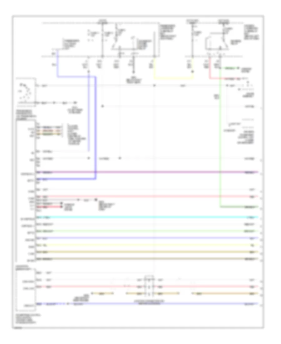 https://portal-diagnostov.com/license.html
Automotive Electricians Portal FZCO
Automotive Electricians Portal FZCO
https://portal-diagnostov.com/license.html
https://portal-diagnostov.com/license.html
Automotive Electricians Portal FZCO
Automotive Electricians Portal FZCOList of elements for Navigation Wiring Diagram (1 of 2) for Acura MDX 2004:
- (can high)
- (can low)
- (under driver's seat)
- (vss out)
- A15
- A16
- A17
- A22
- Acc
- Accessory power socket relay
- Aci
- Aco
- B sig
- B10
- B11
- B12
- B13
- B14
- B15
- B16
- B17
- B18
- B19
- B20
- B21
- B23
- B26
- C sig
- Climate control unit (lower center of dash, forward of center console)
- Clk 2
- Disp bus (+)
- Disp bus (-)
- Driver's
- Driver's underdash fuse/relay box (behind left end of dash)
- Fuse 11 10a
- Fuse 13 7.5a
- Fuse 8 7.5a
- Fuse 9 10a
- Fuse 9 15a
- G sig
- G101 (at left rear of engine)
- G13
- G15
- G502 (behind right center of dash)
- G651 (below right front seat)
- G652 (above right rear fender)
- Gauge assembly
- Gnd
- Gnd sig
- Hot at all times
- Hot in acc or on
- Hot in on or start
- Ill+
- Ill-
- Interior lights system
- Junction connector c501 (behind glove box)
- K11
- M11
- Mirrors system
- Navigation display unit
- Passenger's multiplex control unit
- Passenger's underdash fuse/relay box (behind right kick panel)
- Power seat control unit
- Powertrain control module (pcm) (on right side of engine compt)
- R sig
- Red
- Reverse relay
- Scty1
- Scty2
- Sh disp bus
- Sh sig
- Transmission range switch (on transmission housing)
- W/ memory
Navigation Wiring Diagram (2 of 2) for Acura MDX 2004
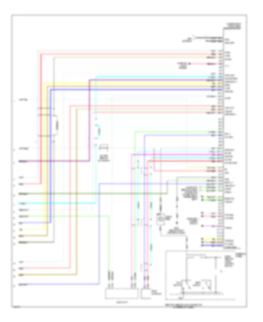 https://portal-diagnostov.com/license.html
Automotive Electricians Portal FZCO
Automotive Electricians Portal FZCO
https://portal-diagnostov.com/license.html
https://portal-diagnostov.com/license.html
Automotive Electricians Portal FZCO
Automotive Electricians Portal FZCOList of elements for Navigation Wiring Diagram (2 of 2) for Acura MDX 2004:
- (under right front seat) navigation unit
- A10
- A11
- A12
- A13
- A14
- A15
- A16
- A17
- A18
- A19
- A20
- Acc
- Audio unit
- B sig
- B10
- B11
- B12
- B13
- B14
- Back
- Back lt
- C sig
- Cable reel
- Can high
- Can low
- Can sh
- D10
- D11
- D12
- D13
- D14
- D15
- D16
- Diag n
- Diag p
- Disp bus (+)
- Disp bus (-)
- G sig
- G502 (behind right center of dash)
- Gnd
- Gnd gps
- Gnd rg
- Gnd sig
- Gps
- Gps antenna
- Ill +
- Interior lights system
- J/c c502 (behind glove box)
- Mic sh
- Mic sig gnd
- Mic sig+
- Mute
- Navigation service check connector (under front passenger's seat)
- Nca
- R sig
- Radio remote/ voice control switch
- Radio sw
- Rearview camera circuit
- Red
- Remote case ground connector (in steering wheel)
- Rg l+
- Rh sg
- Roof console
- Sh disp bus
- Sh sig
- Steering wheel
- Strg sw
- Switch
- Talk
- Tv b sig2
- Tv bus +
- Tv bus -
- Tv c sig2
- Tv g sig2
- Tv gnd sig2
- Tv r sig2
- Vss input
Parking Assistant Wiring Diagram for Acura MDX 2004
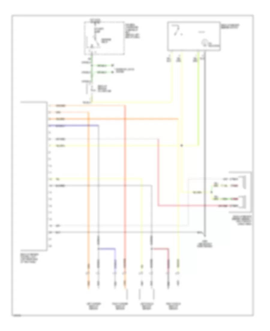 https://portal-diagnostov.com/license.html
Automotive Electricians Portal FZCO
Automotive Electricians Portal FZCO
https://portal-diagnostov.com/license.html
https://portal-diagnostov.com/license.html
Automotive Electricians Portal FZCO
Automotive Electricians Portal FZCOList of elements for Parking Assistant Wiring Diagram for Acura MDX 2004:
- Back-up sensor beeper assembly (right side of cargo area)
- Back-up sensor beeper switch
- Back-up sensor control unit (left rear side of trim panel)
- Back-up sensor in-line fuse
- Driver's underdash fuse/relay box (behind left end of dash)
- Exterior lights system
- Fuse 9 10a
- G652 (above right rear fender)
- Hot in on or start
- Left corner back-up sensor
- Left middle back-up sensor
- On indicator
- Red
- Reverse relay
- Right corner back-up sensor
- Right middle back-up sensor
Rear Camera Wiring Diagram for Acura MDX 2004
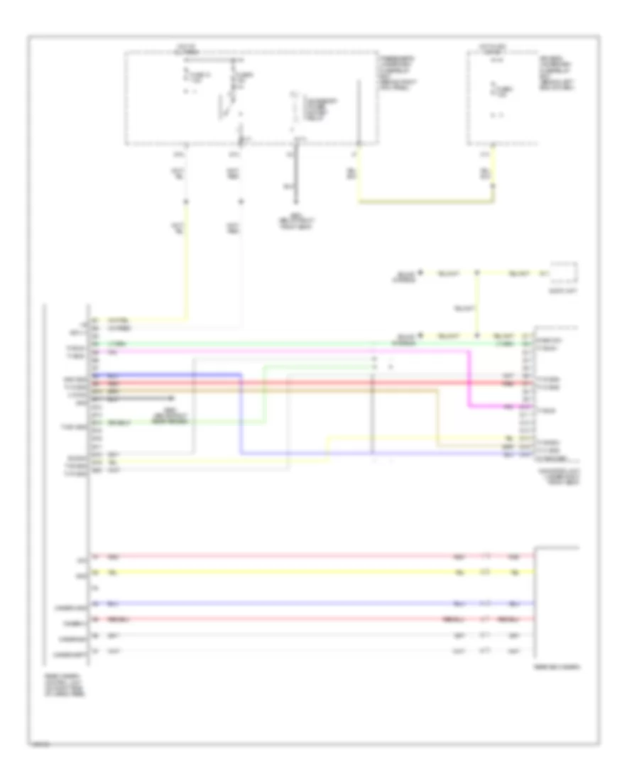 https://portal-diagnostov.com/license.html
Automotive Electricians Portal FZCO
Automotive Electricians Portal FZCO
https://portal-diagnostov.com/license.html
https://portal-diagnostov.com/license.html
Automotive Electricians Portal FZCO
Automotive Electricians Portal FZCOList of elements for Rear Camera Wiring Diagram for Acura MDX 2004:
- + b
- Acc (+)
- Accessory power socket relay
- Audio unit
- B10
- B11
- B12
- B13
- B14
- B15
- B16
- B17
- B18
- B19
- B20
- Bus sh
- C sync
- Camera adpt
- Camera gnd
- Camera sh
- Camera v
- D10
- D11
- D12
- D13
- D14
- D15
- D16
- Driver's underdash fuse/relay box (behind left end of dash)
- Fuse 13 7.5a
- Fuse 8 7.5a
- Fuse 9 15a
- G13
- G15
- G651 (below right front seat)
- G652 (above right rear fender)
- Gnd
- Gnd sig2
- Hot at all times
- Hot in acc or on
- M11
- Navigation unit (under right front seat)
- Passenger's underdash fuse/relay box (behind right kick panel)
- Radio sw
- Rear camera control unit (on right side of cargo area)
- Rearview camera
- Red
- Sound systems
- Tv b sig2
- Tv bus +
- Tv bus -
- Tv c sig2
- Tv g sig2
- Tv gnd sig2
- Tv r sig2
- Tv sh sig2
- Vcc
PASSIVE RESTRAINTS
Passive Restraints Wiring Diagram for Acura MDX 2004
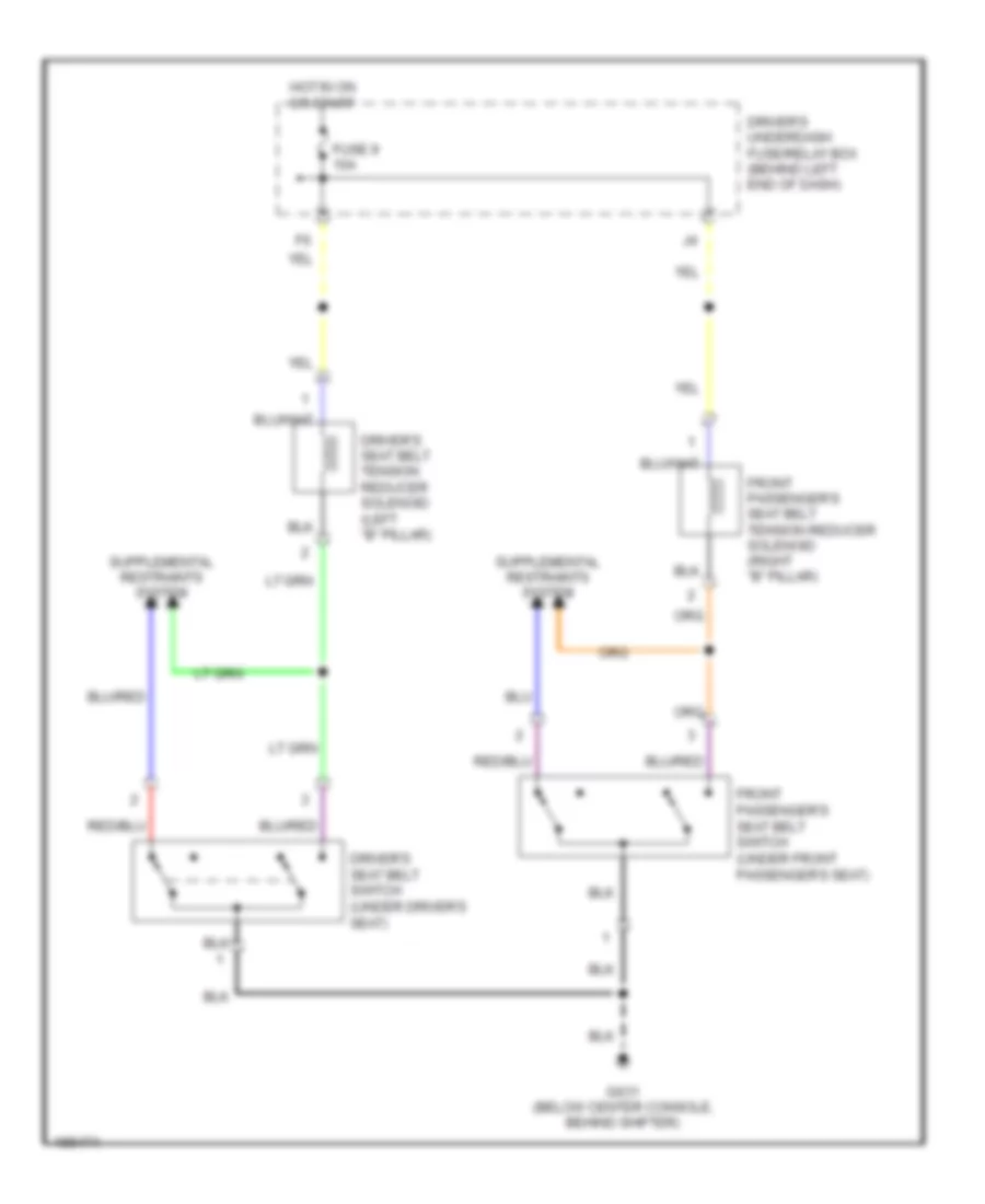 https://portal-diagnostov.com/license.html
Automotive Electricians Portal FZCO
Automotive Electricians Portal FZCO
https://portal-diagnostov.com/license.html
https://portal-diagnostov.com/license.html
Automotive Electricians Portal FZCO
Automotive Electricians Portal FZCOList of elements for Passive Restraints Wiring Diagram for Acura MDX 2004:
- Driver's seat belt switch (under driver's seat)
- Driver's seat belt tension reducer solenoid (left "b" pillar)
- Driver's underdash fuse/relay box (behind left end of dash)
- Front passenger's seat belt switch (under front passenger's seat)
- Front passenger's seat belt tension reducer solenoid (right "b" pillar)
- Fuse 9 10a
- G631 (below center console, behind shifter)
- Hot in on or start
POWER DISTRIBUTION
Power Distribution Wiring Diagram (1 of 4) for Acura MDX 2004
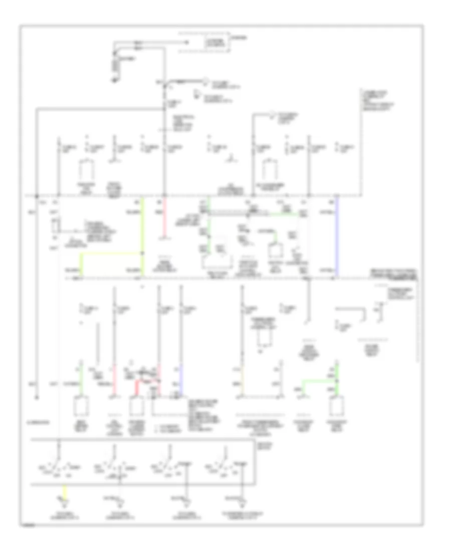 https://portal-diagnostov.com/license.html
Automotive Electricians Portal FZCO
Automotive Electricians Portal FZCO
https://portal-diagnostov.com/license.html
https://portal-diagnostov.com/license.html
Automotive Electricians Portal FZCO
Automotive Electricians Portal FZCOList of elements for Power Distribution Wiring Diagram (1 of 4) for Acura MDX 2004:
- (behind right kick panel)
- (not used)
- A/c compressor clutch relay
- A/c condenser fan relay
- A12
- A17
- Acc
- Alternator
- Battery
- D10
- Data link connector
- Driver's lumbar support switch
- Driver's power seat control unit (w/ memory) driver's power seat adjustment switch (w/o memory)
- Driver's underdash fuse/relay box (behind left end of dash)
- Drl control unit (canada)
- Electrical load detector (eld) unit
- Front blower motor relay
- Front passenger's power seat adjustment switch (w/ memory)
- Fuse 1 30a
- Fuse 14 20a
- Fuse 2 20a
- Fuse 3 20a
- Fuse 4 20a
- Fuse 41 120a
- Fuse 42 50a
- Fuse 46 15a
- Fuse 5 20a
- Fuse 51 40a
- Fuse 52 30a
- Fuse 53 30a
- Fuse 55 40a
- Fuse 56 40a
- Fuse 57 30a
- Fuse 58 30a
- Fuse 59 7.5a
- Fuse 6 10a
- G18
- G8 (not used)
- H18
- Ignition coil relay
- Ignition switch
- J/c c404 (under left side of dash)
- Lock
- Moonroof close relay
- Moonroof open relay
- Off
- Option connector
- Passenger's multiplex control unit
- Passenger's underdash fuse/relay box
- Pgm-fi main relay 1
- Power window relay
- Radiator fan relay
- Rear blower motor relay
- Rear window defogger relay
- Red
- Seat heater relay
- Start
- Starter
- Starter solenoid
- T101
- Throttle actuator control module relay
- To fuse 4 (diagram 2 of 4)
- To fuse 47 (diagram 3 of 4)
- To fuse 54 (diagram 3 of 4)
- To fuse 6 (diagram 2 of 4)
- To fuse 7 (diagram 4 of 4)
- To fuse 8 (diagram 4 of 4)
- To starter cut relay (diagram 4 of 4)
- Under-hood fuse/relay box (at right side of engine compt)
- W/ memory
- W/o memory
Power Distribution Wiring Diagram (2 of 4) for Acura MDX 2004
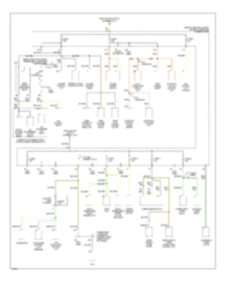 https://portal-diagnostov.com/license.html
Automotive Electricians Portal FZCO
Automotive Electricians Portal FZCO
https://portal-diagnostov.com/license.html
https://portal-diagnostov.com/license.html
Automotive Electricians Portal FZCO
Automotive Electricians Portal FZCOList of elements for Power Distribution Wiring Diagram (2 of 4) for Acura MDX 2004:
- (behind left end of dash) driver's underdash fuse/relay box
- (behind right kick panel) passenger's underdash fuse/relay box
- (not h17
- (not used)
- A/c compressor clutch relay
- A/c condenser fan relay
- A/c diode b
- A19
- Alternator
- Automatic dimming inside mirror
- Automatic lighting control unit
- Automatic wiper relay
- Auxiliary fuse holder 2
- B10
- B13
- Climate control panel
- Climate control unit
- D11
- D13
- D16
- D16 (not used)
- Drl control unit (canada)
- Electrical compass unit
- F8 (not used)
- Fan control relay
- From ignition switch (diagram 1 of 4)
- Front blower motor relay
- Front passenger's airbag cut-off indicator
- Front passenger's weight sensor unit
- Fuse 10 7.5a
- Fuse 11 10a
- Fuse 12 30a
- Fuse 3 7.5a
- Fuse 4 7.5a
- Fuse 5 10a
- Fuse 6 15a
- Fuse 7 7.5a
- Fuse 92 7.5a
- G1 (not used)
- G17
- H12
- H17
- Hazard warning switch
- Immobilizer control unit- receiver
- Intermittent wiper relay
- J12
- J14
- J15
- L14
- M13
- M14
- M15
- Multi- information display unit
- Opds unit
- Option connector
- Passenger's underdash fuse/relay box (behind right kick panel)
- Pcm
- Power mirror switch
- Rear blower motor relay
- Rear heater-a/c control panel unit
- Rear mode control motor
- Rear window defogger relay
- Rear window wiper intermittent control unit
- Rear window wiper motor
- Recirculation control motor
- Seat heater relay
- To fuse 1 (diagram 4 of 4)
- Under-hood fuse/relay box (at right side of engine compt)
- Used)
- Vsa modulator- control unit
- W/ auto wiper
- W/o navigation
- Windshield wiper motor
- Wiper/washer switch
Power Distribution Wiring Diagram (3 of 4) for Acura MDX 2004
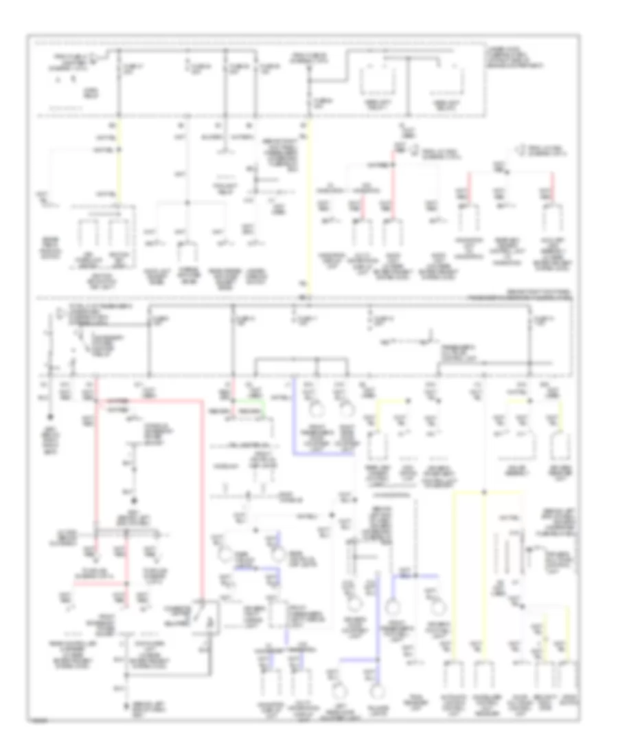 https://portal-diagnostov.com/license.html
Automotive Electricians Portal FZCO
Automotive Electricians Portal FZCO
https://portal-diagnostov.com/license.html
https://portal-diagnostov.com/license.html
Automotive Electricians Portal FZCO
Automotive Electricians Portal FZCOList of elements for Power Distribution Wiring Diagram (3 of 4) for Acura MDX 2004:
- (behind left end of dash) driver's underdash fuse/relay box
- (behind left end of dash) g501
- (behind right kick panel) passenger's underdash fuse/relay box
- (not used)
- (w/ navigation)
- A10
- A12
- A23
- A24
- A7 (not used)
- Accessory power socket relay
- Audio unit (except bose)
- Audio unit (w/ rear entertainment system (dvd))
- Audio unit (w/o rear entertainment system (dvd))
- Automatic lighting control unit
- Auxiliary jack assembly (w/ rear entertainment system (dvd))
- B15
- B17
- Brake pedal position switch
- C11
- C19
- Cigarette lighter (if equipped)
- Console accessory power socket
- Control unit (w/ memory)
- Door multiplex control unit
- Dpms switch
- Driver's door courtesy light
- Driver's footwell light
- Driver's multiplex control unit
- Driver's power seat
- Driver's vanity mirror light
- Dvd player unit (w/ rear entertainment system (dvd))
- E10
- Foglight relay
- From fuse 41 & battery (diagram 1 of 4)
- From fuse 59 (diagram 1 of 4)
- From j/c c502 (diagram 3 of 4)
- Front accessory power socket
- Front individual map lights
- Front passenger's door courtesy light
- Front passenger's footwell light
- Front passenger's vanity mirror light
- Fuse 10 15a
- Fuse 11 10a
- Fuse 12 20a
- Fuse 13 7.5a
- Fuse 47 20a
- Fuse 48 20a
- Fuse 49 15a
- Fuse 50 20a
- Fuse 54 40a
- Fuse 9 15a
- G11
- G13
- G15
- G16
- G501 (behind left end of dash)
- G651 (below right front seat)
- Gauge assembly
- H15
- Hazard warning switch
- Headlight relay 1
- Headlight relay 2
- Homelink
- Horn relay
- I12
- I16
- Ignition key light
- Ignition key switch/ key light
- Immobilizer control unit- receiver
- J/c c502 (behind glove box)
- J11
- Key interlock switch
- Keyless receiver unit
- Left rear door courtesy light
- M19
- Multi- information display unit
- Navi- gation unit
- Navigation display unit
- Navigation unit (w/ navigation)
- Passenger's multiplex control unit
- Rear ceiling lights
- Rear controller & screen (w/ rear entertainment system (dvd))
- Rear individual map lights
- Rear stereo amplifier (except bose)
- Rear view camera control unit
- Rearview cemera control unit (w/ navigation)
- Right rear door courtesy light
- Roof console
- Security indic- ator
- Stereo amplifier (bose)
- Tailgate lights
- Taillight relay
- To pin j7 of passenger's under-dash fuse/relay box (diagram 4 of 4)
- To splice (diagram 3 of 4)
- Tpms receiver unit
- Under-hood fuse/relay box (at right side of engine compartment)
- W/ navigation
- W/o navigation
Power Distribution Wiring Diagram (4 of 4) for Acura MDX 2004
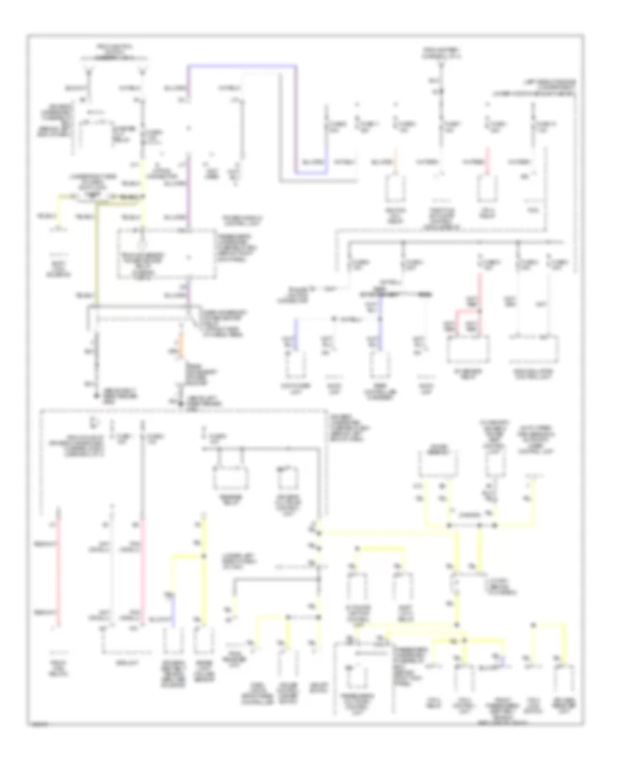 https://portal-diagnostov.com/license.html
Automotive Electricians Portal FZCO
Automotive Electricians Portal FZCO
https://portal-diagnostov.com/license.html
https://portal-diagnostov.com/license.html
Automotive Electricians Portal FZCO
Automotive Electricians Portal FZCOList of elements for Power Distribution Wiring Diagram (4 of 4) for Acura MDX 2004:
- (above left rear fender) g602
- (above right rear fender) g652
- (auto wiper)
- (canada)
- (left side of engine compartment) under-hood fuse sub-fuse box
- (not used)
- (under left side of dash) j/c c404
- (under right side of dash) shift lock diode
- (w/ memory) driver's power seat control unit
- A/f sensor relay
- A10
- A17
- A18
- A20
- A22
- A24
- Audio unit
- Automatic lighting control unit
- Bose
- Brake light failure sensor
- C10
- C13
- Cruise control master switch
- Dash lights brightness controller
- Driver's multiplex control unit
- Driver's seat belt tension reducer solenoid
- Driver's underdash fuse/relay box (behind left end of dash)
- Dvd player unit
- From accessory power socket relay (diagram 3 of 4)
- From battery (diagram 1 of 4)
- From ignition switch (diagram 1 of 4)
- From pin a5 of driver's under-dash fuse/relay box (diagram 2 of 4)
- Front passenger's seat belt tension reducer solenoid
- Fuse 1 15a
- Fuse 1 20a
- Fuse 10 7.5a
- Fuse 11 20a
- Fuse 2 10a
- Fuse 2 40a
- Fuse 3 30a
- Fuse 4 20a
- Fuse 5 15a
- Fuse 6 20a
- Fuse 7 15a
- Fuse 8 15a
- Fuse 8 7.5a
- Fuse 9 10a
- Fuse 9 15a
- Gauge assembly
- Ignition coil relay
- J/c c501 (behind glove box)
- J17
- J18
- Keyless receiver unit
- M11
- Option connector
- Passenger's multiplex control unit
- Passenger's underdash fuse/relay box (behind right kick panel)
- Passenger's underdash fuse/relay box (behind right kick panel)
- Pcm
- Pgm-fi main relay 2
- Power window control unit
- Rain sensor & automatic wiper control unit
- Rear accessory power socket
- Rear accessory power socket relay (at right side of cargo area)
- Rear controller & screen
- Rear entertainment
- Reverse relay
- Shift lock relay
- Shift lock solenoid
- Srs unit
- Starter cut relay
- Throttle actuator control module relay
- Tpms receiver unit
- Trailer lighting connector
- Vsa modulator- control unit
- Vsa off switch
- Vtm-4 control unit
- Vtm-4 lock switch
- Vtm-4 relay
POWER MIRRORS
Automatic Day/Night Mirror Wiring Diagram for Acura MDX 2004
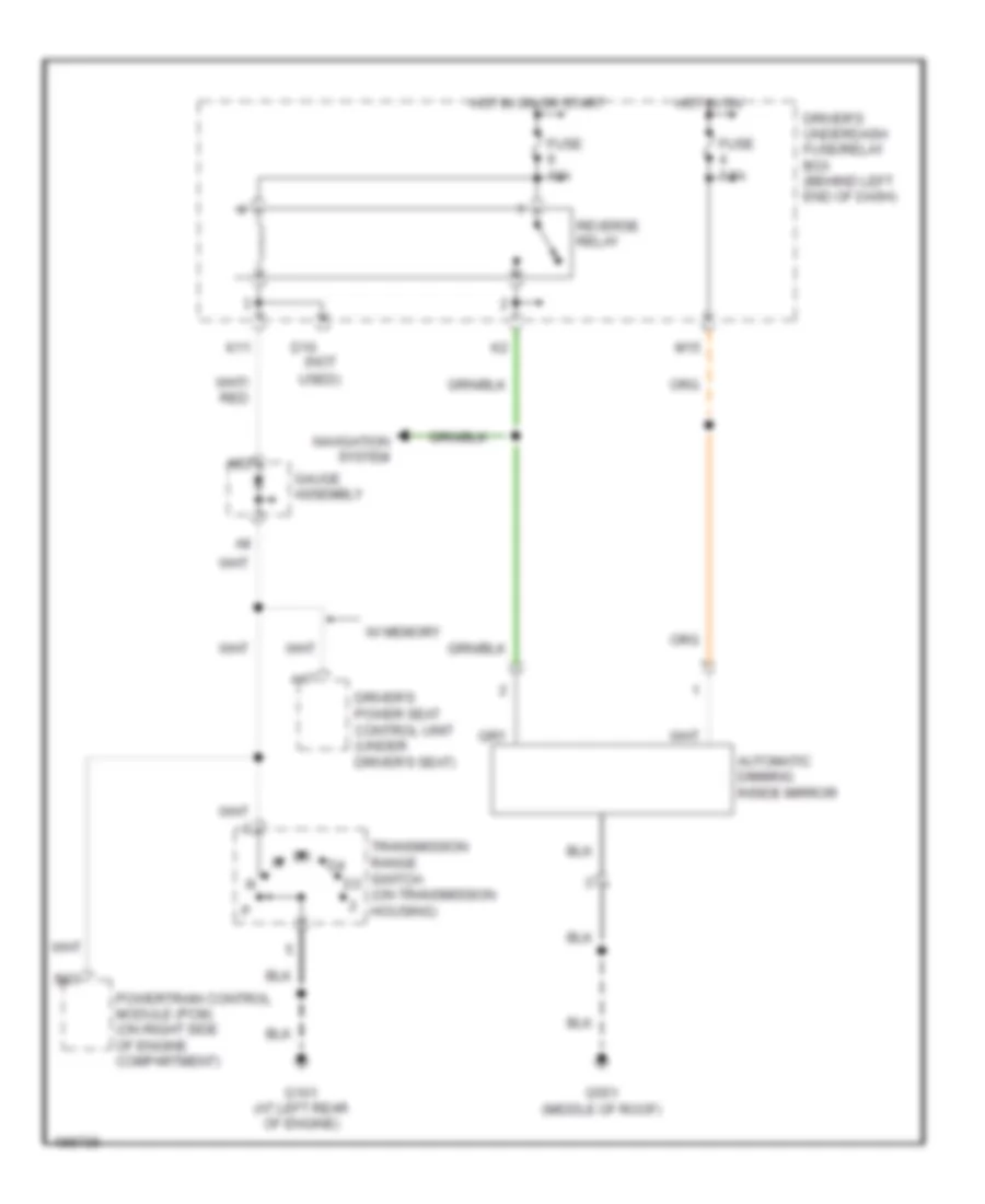 https://portal-diagnostov.com/license.html
Automotive Electricians Portal FZCO
Automotive Electricians Portal FZCO
https://portal-diagnostov.com/license.html
https://portal-diagnostov.com/license.html
Automotive Electricians Portal FZCO
Automotive Electricians Portal FZCOList of elements for Automatic Day/Night Mirror Wiring Diagram for Acura MDX 2004:
- A17
- A22
- Automatic dimming inside mirror
- B23
- D10 (not used)
- Driver's power seat control unit (under driver's seat)
- Driver's underdash fuse/relay box (behind left end of dash)
- Fuse 10a
- Fuse 7.5a
- G101 (at left rear of engine)
- G551 (middle of roof)
- Gauge assembly
- Hot in on
- Hot in on or start
- K11
- M15
- Navigation system
- Powertrain control module (pcm) (on right side of engine compartment)
- Reverse relay
- Transmission range switch (on transmission housing)
- W/ memory
Power Mirrors Wiring Diagram, without Memory for Acura MDX 2004
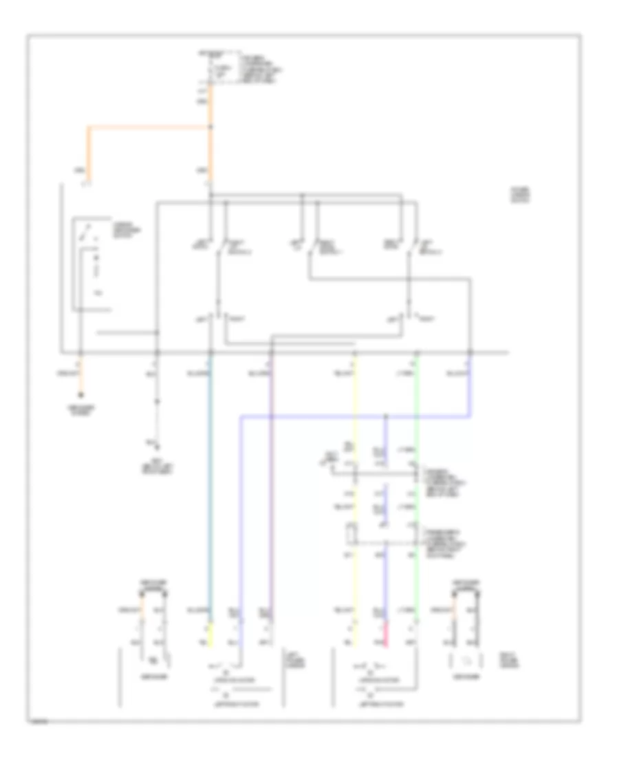 https://portal-diagnostov.com/license.html
Automotive Electricians Portal FZCO
Automotive Electricians Portal FZCO
https://portal-diagnostov.com/license.html
https://portal-diagnostov.com/license.html
Automotive Electricians Portal FZCO
Automotive Electricians Portal FZCOList of elements for Power Mirrors Wiring Diagram, without Memory for Acura MDX 2004:
- (not used)
- Defogger
- Defogger system
- Driver's underdash fuse/relay box (behind left end of dash)
- E11
- E19
- Fuse 4 7.5a
- G601 (below left front seat)
- H11
- H15
- H17
- Hot in on
- J12
- J13
- Left
- Left down
- Left power mirror
- Left up
- Left up switch 3
- Left/right motor
- M16
- M17
- Mirror defogger switch
- Passenger's underdash fuse/relay box (behind right kick panel)
- Pnk
- Power mirror switch
- Right
- Right down
- Right down switch 1
- Right power mirror
- Right up switch 2
- Up/down motor
POWER SEATS
Driver Power Seat Wiring Diagram, without Memory for Acura MDX 2004
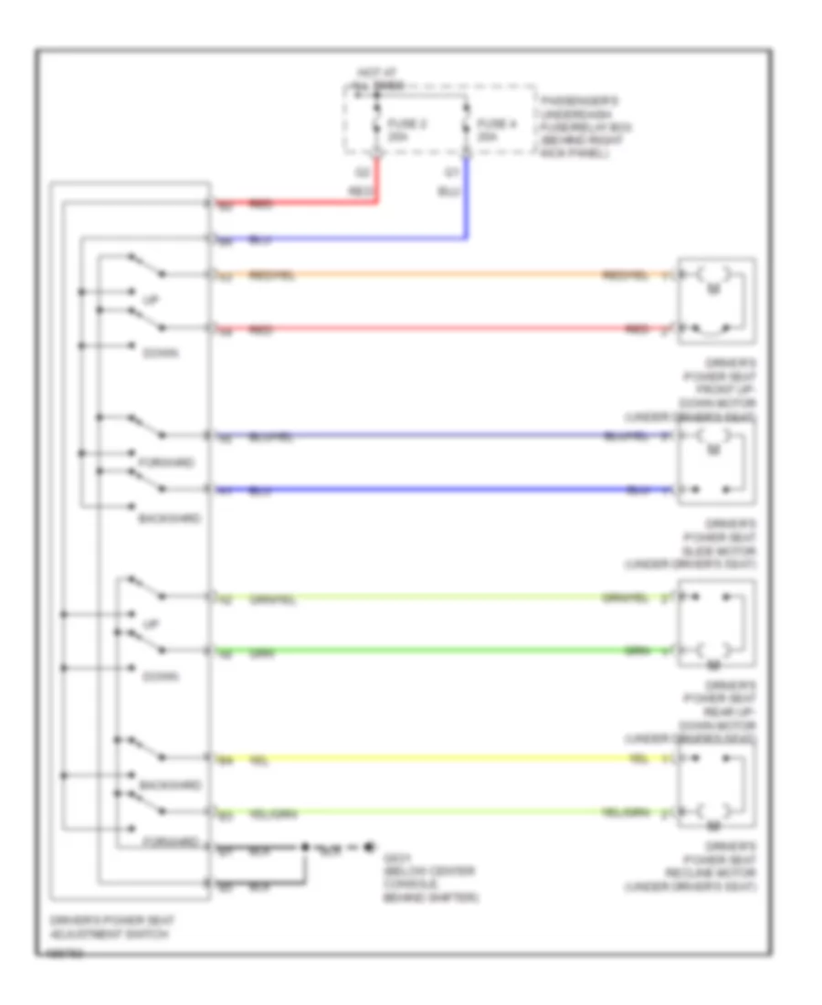 https://portal-diagnostov.com/license.html
Automotive Electricians Portal FZCO
Automotive Electricians Portal FZCO
https://portal-diagnostov.com/license.html
https://portal-diagnostov.com/license.html
Automotive Electricians Portal FZCO
Automotive Electricians Portal FZCOList of elements for Driver Power Seat Wiring Diagram, without Memory for Acura MDX 2004:
- Backward
- Down
- Driver's power seat adjustment switch
- Driver's power seat front up- down motor (under driver's seat)
- Driver's power seat rear up- down motor (under driver's seat)
- Driver's power seat recline motor (under driver's seat)
- Driver's power seat slide motor (under driver's seat)
- Forward
- Fuse 2 20a
- Fuse 4 20a
- G631 (below center console, behind shifter)
- Hot at all times
- Passenger's underdash fuse/relay box (behind right kick panel)
- Red
Heated Seats Wiring Diagram for Acura MDX 2004
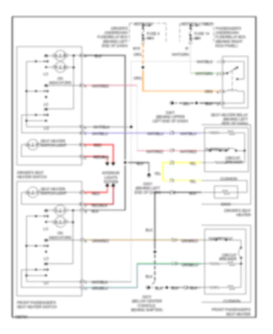 https://portal-diagnostov.com/license.html
Automotive Electricians Portal FZCO
Automotive Electricians Portal FZCO
https://portal-diagnostov.com/license.html
https://portal-diagnostov.com/license.html
Automotive Electricians Portal FZCO
Automotive Electricians Portal FZCOList of elements for Heated Seats Wiring Diagram for Acura MDX 2004:
- Back
- Circuit breaker
- Cushion
- Driver's seat heater
- Driver's seat heater switch
- Driver's underdash fuse/relay box (behind left end of dash)
- Front passenger's seat heater
- Front passenger's seat heater switch
- Fuse 14 20a
- Fuse 4 7.5a
- G401 (behind upper left end of dash)
- G501 (behind left end of dash)
- G631 (below center console, behind shifter)
- Hot at all times
- Hot in on
- Interior lights system
- M15
- On indicators
- Passenger's underdash fuse/relay box (behind right kick panel)
- Red
- Seat heater relay (behind left side of dash)
- Seat heater switch light
- Thermostat
Passenger Power Seat Wiring Diagram for Acura MDX 2004
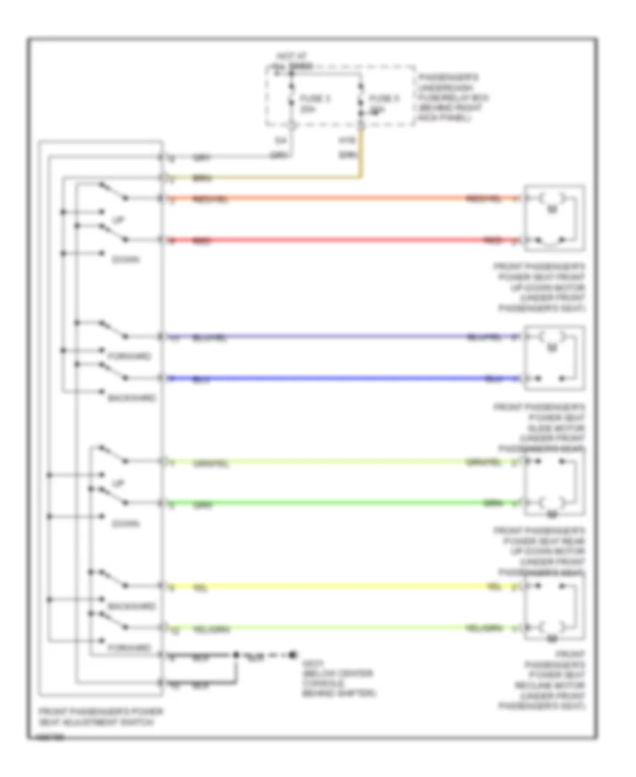 https://portal-diagnostov.com/license.html
Automotive Electricians Portal FZCO
Automotive Electricians Portal FZCO
https://portal-diagnostov.com/license.html
https://portal-diagnostov.com/license.html
Automotive Electricians Portal FZCO
Automotive Electricians Portal FZCOList of elements for Passenger Power Seat Wiring Diagram for Acura MDX 2004:
- Backward
- Down
- Forward
- Front passenger's power seat adjustment switch
- Front passenger's power seat front up-down motor (under front passenger's seat)
- Front passenger's power seat rear up-down motor (under front passenger's seat)
- Front passenger's power seat recline motor (under front passenger's seat)
- Front passenger's power seat slide motor (under front passenger's seat)
- Fuse 3 20a
- Fuse 5 20a
- G631 (below center console, behind shifter)
- H18
- Hot at all times
- Passenger's underdash fuse/relay box (behind right kick panel)
- Red
POWER TOP/SUNROOF
Power Top/Sunroof Wiring Diagram for Acura MDX 2004
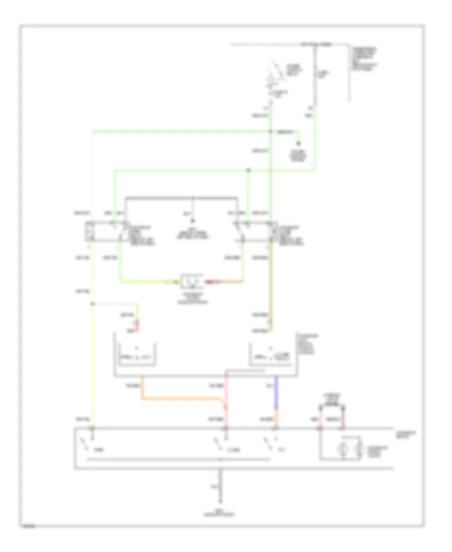 https://portal-diagnostov.com/license.html
Automotive Electricians Portal FZCO
Automotive Electricians Portal FZCO
https://portal-diagnostov.com/license.html
https://portal-diagnostov.com/license.html
Automotive Electricians Portal FZCO
Automotive Electricians Portal FZCOList of elements for Power Top/Sunroof Wiring Diagram for Acura MDX 2004:
- Close
- Close or tilt
- Fuse 1 30a
- Fuse 15 7.5a
- G401 (behind upper left end of dash)
- G551 (middle of roof)
- Hot at all times
- I10
- Interior lights system
- Moonroof close relay (behind left side of dash)
- Moonroof limit switch (middle of roof)
- Moonroof motor (middle of roof)
- Moonroof open relay (behind left side of dash)
- Moonroof switch
- Moonroof switch lights
- Open
- Passenger's under-dash fuse/relay box (behind right kick panel)
- Power window relay
- Power windows system
- Red
- Tilt
POWER WINDOWS
Power Windows Wiring Diagram (1 of 2) for Acura MDX 2004
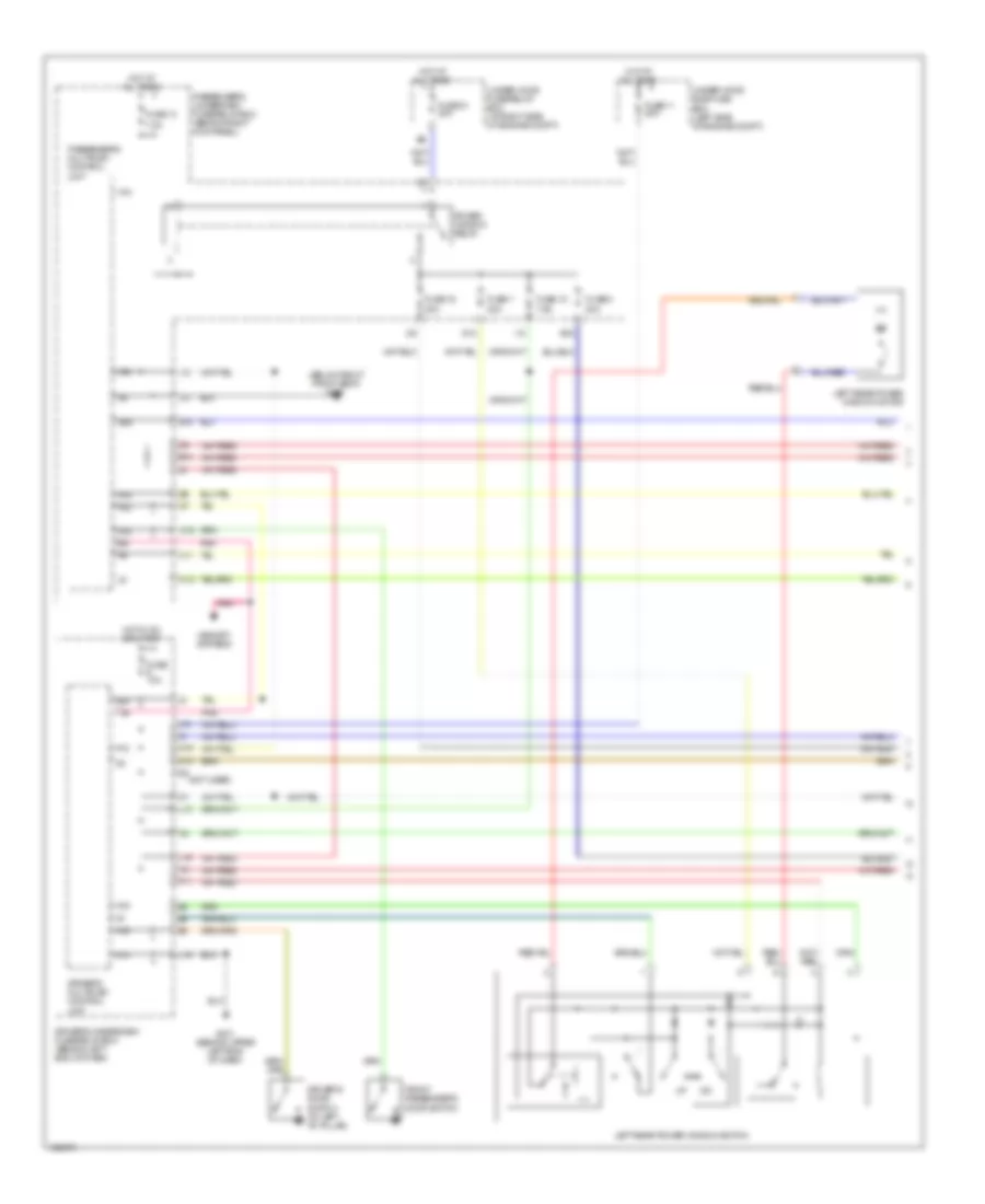 https://portal-diagnostov.com/license.html
Automotive Electricians Portal FZCO
Automotive Electricians Portal FZCO
https://portal-diagnostov.com/license.html
https://portal-diagnostov.com/license.html
Automotive Electricians Portal FZCO
Automotive Electricians Portal FZCOList of elements for Power Windows Wiring Diagram (1 of 2) for Acura MDX 2004:
- (below right front seat) g651
- (not used)
- 7.5a
- A12
- A14
- A15
- A16
- A18
- A19
- A22
- A24
- C11
- C12
- C16
- Driver's door switch (at left "b" pillar)
- Driver's multiplex control unit
- Driver's underdash fuse/relay box (behind left end of dash)
- E14
- E16
- E18
- F11
- Front passenger's door switch
- Fuse 10a
- Fuse 11 20a
- Fuse 13
- Fuse 15 7.5a
- Fuse 16 20a
- Fuse 51 40a
- Fuse 7 20a
- Fuse 8 20a
- G10
- G401 (behind upper left end of dash)
- H14
- Hot at all times
- Hot in on or start
- I10
- I12
- J18
- L13
- L15
- L16
- Left rear power window motor
- Left rear power window switch
- M19
- Memory systems
- Passenger's multiplex control unit
- Passenger's underdash fuse/relay box (behind right kick panel)
- Pnk
- Power window relay
- Under-hood fuse/relay box (at right side of engine compt)
- Under-hood sub-fuse box (left side of engine compt)
Power Windows Wiring Diagram (2 of 2) for Acura MDX 2004
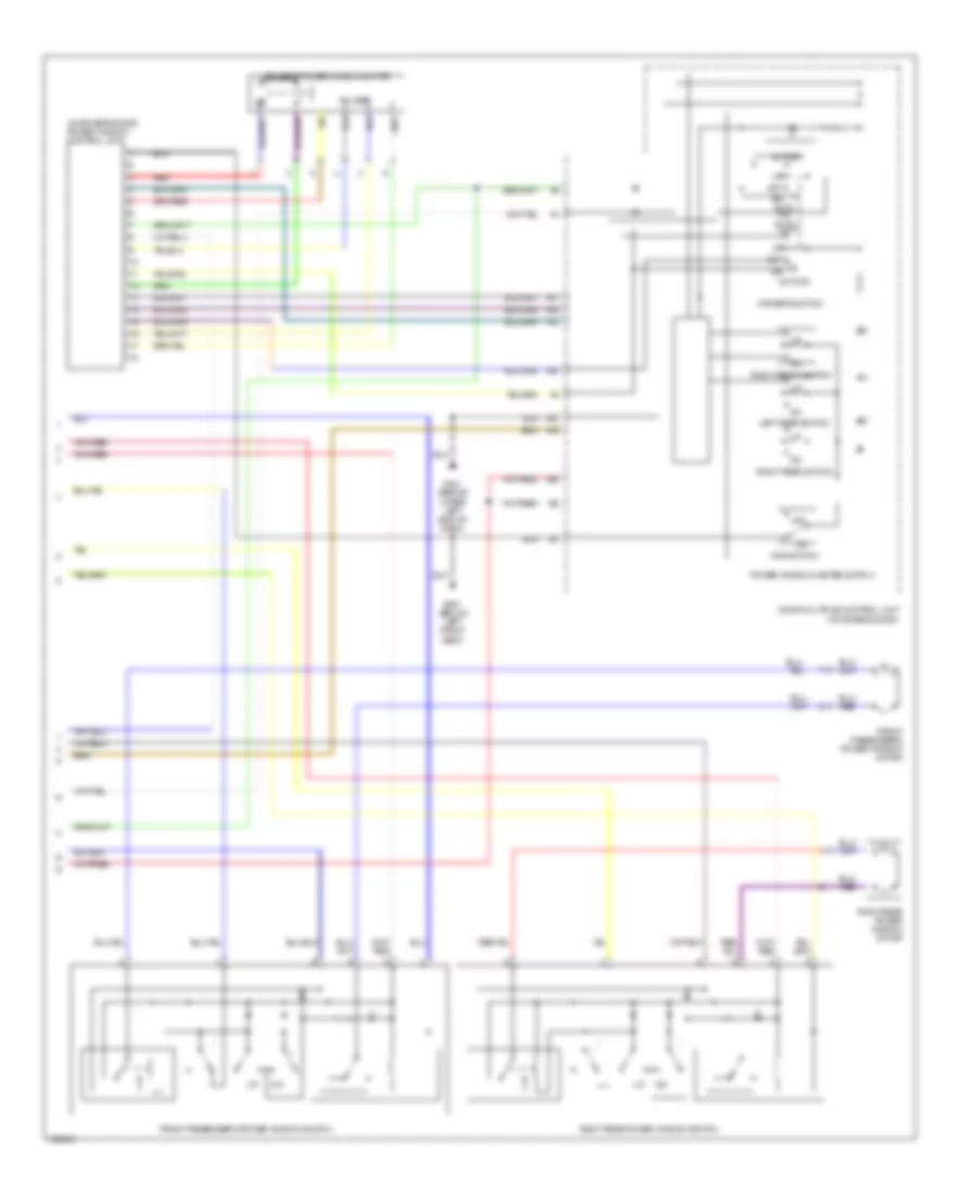 https://portal-diagnostov.com/license.html
Automotive Electricians Portal FZCO
Automotive Electricians Portal FZCO
https://portal-diagnostov.com/license.html
https://portal-diagnostov.com/license.html
Automotive Electricians Portal FZCO
Automotive Electricians Portal FZCOList of elements for Power Windows Wiring Diagram (2 of 2) for Acura MDX 2004:
- (in driver's door)
- (in driver's door) power window control unit
- A10
- A11
- A12
- A13
- A14
- A15
- A20
- Auto dn
- Auto up
- Dn auto dn
- Door multiplex control unit
- Driver's power window motor
- Driver's switch
- Front passenger's power window motor
- Front passenger's power window switch
- G401 (behind upper left end of dash)
- G601 (below left front seat)
- Left rear switch
- Main switch
- Off
- Power window master switch
- Pulser
- Red
- Right front switch
- Right rear power window motor
- Right rear power window switch
- Right rear switch
RADIO
Radio Wiring Diagram, withBOSE (1 of 2) for Acura MDX 2004
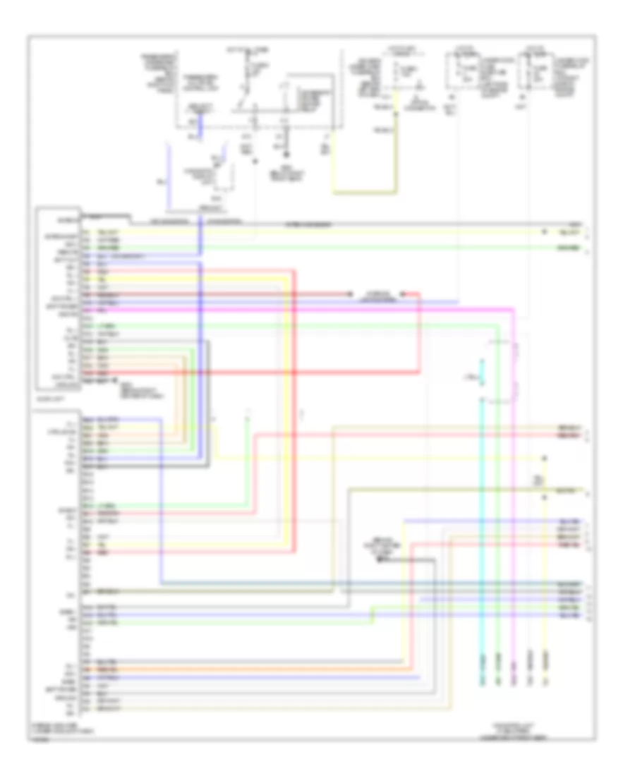 https://portal-diagnostov.com/license.html
Automotive Electricians Portal FZCO
Automotive Electricians Portal FZCO
https://portal-diagnostov.com/license.html
https://portal-diagnostov.com/license.html
Automotive Electricians Portal FZCO
Automotive Electricians Portal FZCOList of elements for Radio Wiring Diagram, withBOSE (1 of 2) for Acura MDX 2004:
- (behind right center of dash) g502
- +rr
- -rr
- A10
- A11
- A12
- A13
- A14
- A15
- A16
- A17
- A18
- A19
- A20
- Acc+
- Accessory power socket relay
- Antenna
- Antenna amp
- Antenna sublead
- Audio unit
- B10
- B11
- B12
- B13
- B14
- B15
- B16
- B17
- B18
- B19
- B20
- B21
- B22
- B23
- Bass +
- Bass-
- Batt power
- Ctrl sw b+
- Dim ctrl +
- Dim ctrl -
- Driver's under-dash fuse/relay box (behind left end of dash)
- Fl +
- Fl -
- Fl-
- Fr +
- Fr -
- Fuse 20a
- Fuse 8 7.5a
- Fuse 9 15a
- G13
- G502 (behind right center of dash)
- G651 (below right front seat)
- Gnd rg
- Ground
- Hot at all times
- Hot in acc or on
- Interior lights system
- M11
- Mute
- Navigation display unit
- Navigation unit (if equipped) (under right front seat)
- Nca
- Passenger's multiplex control unit
- Passenger's underdash fuse/relay box (behind right kick panel)
- Red
- Remote
- Rl +
- Rl -
- Rl-
- Rr +
- Rr -
- S option connector
- Scty out
- Security input
- Shield
- Stereo amplifier (under middle of dash)
- Under-hood fuse sub-fuse box (left side of engine compt)
- Under-hood fuse/relay box (at right side of engine compt)
- W/ navigation
- W/o navigation
Radio Wiring Diagram, withBOSE (2 of 2) for Acura MDX 2004
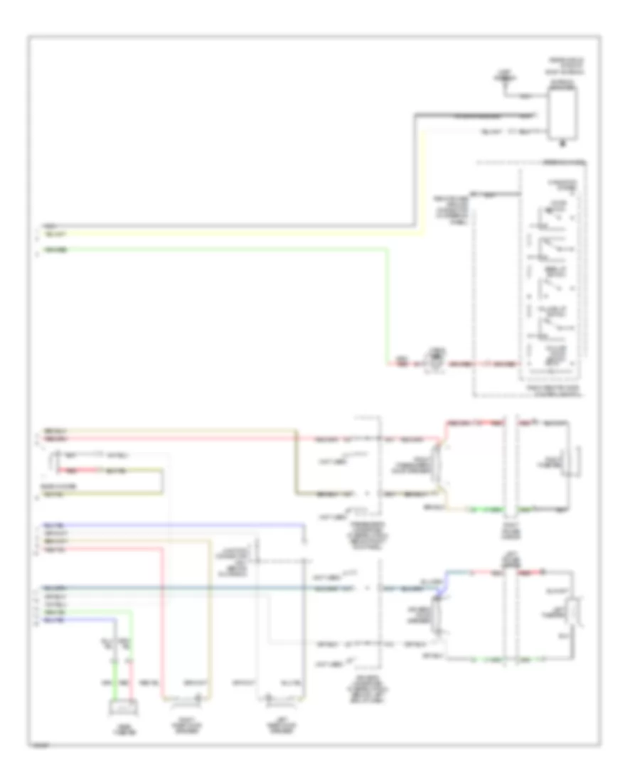 https://portal-diagnostov.com/license.html
Automotive Electricians Portal FZCO
Automotive Electricians Portal FZCO
https://portal-diagnostov.com/license.html
https://portal-diagnostov.com/license.html
Automotive Electricians Portal FZCO
Automotive Electricians Portal FZCOList of elements for Radio Wiring Diagram, withBOSE (2 of 2) for Acura MDX 2004:
- (not used)
- (rear middle of roof) roof antenna
- Antenna amplifier
- Antenna sublead
- Cable reel
- Driver's door speaker
- Driver's underdash fuse/relay box (behind left end of dash)
- E12
- E13
- Front passenger's door speaker
- H12
- H13
- J10
- J11
- Junction connector c501 (behind glove box)
- Left power mirror
- Left rear door speaker
- Left tweeter
- Mast antenna
- Mode switch
- Navigation system
- Nca
- Passenger's underdash fuse/relay box (behind right kick panel)
- Radio remote/voice control switch
- Rear tweeter
- Rear woofer
- Red
- Remote case ground connector (in steering wheel)
- Right power mirror
- Right rear door speaker
- Right tweeter
- Seek up switch
- Steering wheel
- Volume down switch
- Volume up switch
Radio Wiring Diagram, without Bose System for Acura MDX 2004
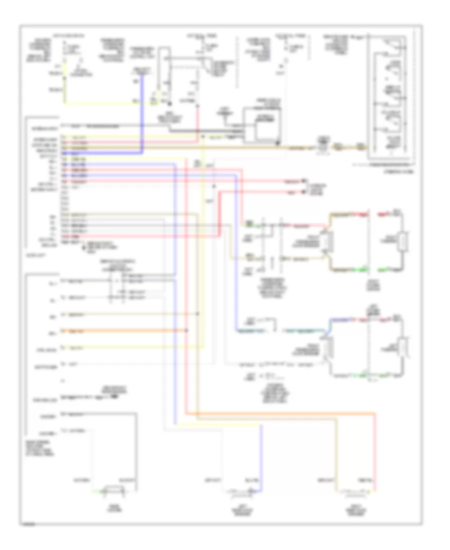 https://portal-diagnostov.com/license.html
Automotive Electricians Portal FZCO
Automotive Electricians Portal FZCO
https://portal-diagnostov.com/license.html
https://portal-diagnostov.com/license.html
Automotive Electricians Portal FZCO
Automotive Electricians Portal FZCOList of elements for Radio Wiring Diagram, without Bose System for Acura MDX 2004:
- (above right rear fender) g652
- (behind glove box) junction connector c501
- (behind right center of dash) g502
- (not used)
- (rear middle of roof) roof antenna
- A10
- A11
- A12
- A13
- A14
- A15
- A16
- A17
- A18
- A19
- A20
- Accessory power socket relay
- Antenna amp
- Antenna amplifier
- Antenna input
- Antenna sublead
- Audio unit
- B21
- Batt power
- Battery input
- Cable reel
- Ctrl sw b+
- Dim ctrl +
- Dim ctrl -
- Driver's underdash fuse/relay box (behind left end of dash)
- E12
- E13
- Fl +
- Fl -
- Fr +
- Fr -
- Front passenger's door speaker
- Fuse 48 20a
- Fuse 8 7.5a
- Fuse 9 15a
- G13
- G651 (below right front seat)
- Ground
- H12
- H13
- Hot at all times
- Hot in acc or on
- Interior lights system
- J10
- J11
- Left power mirror
- Left rear door speaker
- Left tweeter
- M11
- Mast antenna
- Mode switch
- Nca
- Option connector
- Passenger's multiplex control unit
- Passenger's underdash fuse/relay box (behind right kick panel)
- Pwr ground
- Radio remote switch
- Rear stereo amplifier (at right side of cargo area)
- Rear woofer
- Red
- Remote case ground connector (in steering wheel)
- Remote sw
- Right power mirror
- Right rear door speaker
- Right tweeter
- Rl +
- Rl -
- Rr +
- Rr -
- Scty out
- Security input
- Seek up switch
- Steering wheel
- Switched ign
- Under-hood fuse/relay box (at right side of engine compt)
- Volume down switch
- Volume up switch
- Woofer +
- Woofer -
Rear Seat Entertainment Wiring Diagram, with Bose System (1 of 2) for Acura MDX 2004
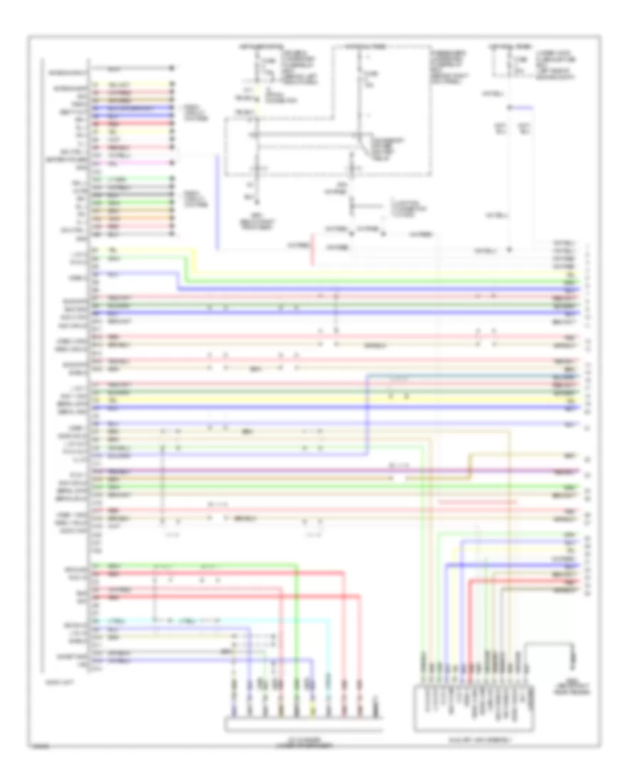 https://portal-diagnostov.com/license.html
Automotive Electricians Portal FZCO
Automotive Electricians Portal FZCO
https://portal-diagnostov.com/license.html
https://portal-diagnostov.com/license.html
Automotive Electricians Portal FZCO
Automotive Electricians Portal FZCOList of elements for Rear Seat Entertainment Wiring Diagram, with Bose System (1 of 2) for Acura MDX 2004:
- (+b)
- A10
- A11
- A12
- A13
- A14
- A15
- A16
- A17
- A18
- A19
- A20
- Acc
- Acc +
- Accessory power socket relay
- Antenna amp
- Antenna input
- Aud 1 com
- Aud 2 com
- Aud 2 shld
- Aud 3 com
- Aud 3 shield
- Aud 3 shld
- Audio 3 shld
- Audio com
- Audio shld
- Audio unit
- Auxiliary jack assembly
- B10
- B11
- B12
- B13
- B14
- B15
- B16
- Battery power
- Bus
- Bus data
- Bus gnd
- C10
- C11
- C12
- C13
- C14
- C15
- C16
- C17
- C18
- C19
- C20
- C21
- C22
- Cd changer (under driver's seat)
- Com chk
- D10
- D11
- D12
- D13
- D14
- Dim ctrl +
- Dim ctrl -
- Driver's underdash fuse/relay box (behind left end of dash)
- Fl +
- Fl -
- Fr +
- Fr -
- Fuse 15a
- Fuse 20a
- Fuse 7.5a
- G13 g13
- G651 (below right front seat)
- G652 (above right rear fender)
- Ga-net gnd
- Gnd
- Ground
- Hot at all times
- Hot in acc or on
- Ill 8v
- Junction connector j/c c502
- L ch 1
- L ch 2
- L ch 3
- L ch in
- L ch out
- M11
- Mute
- Nca
- Option connector
- Passenger's underdash fuse/relay box (behind right kick panel)
- R ch 1
- R ch 2
- R ch 3
- R ch in
- R ch out
- Radio
- Radio circuit (w/o rse)
- Red
- Rg l+
- Rl +
- Rr +
- Rr -
- Secty out
- Serial data
- Serial gnd
- Serial shld
- Shield
- Sig shld
- Under-hood fuse sub-fuse box (left side of engine compt)
- Vid 3 shield
- Video 1
- Video 1 gnd
- Video 1 shld
- Video 2
- Video 2 gnd
- Video 2 shld
- Video 3
- Video 3 gnd
Rear Seat Entertainment Wiring Diagram, with Bose System (2 of 2) for Acura MDX 2004
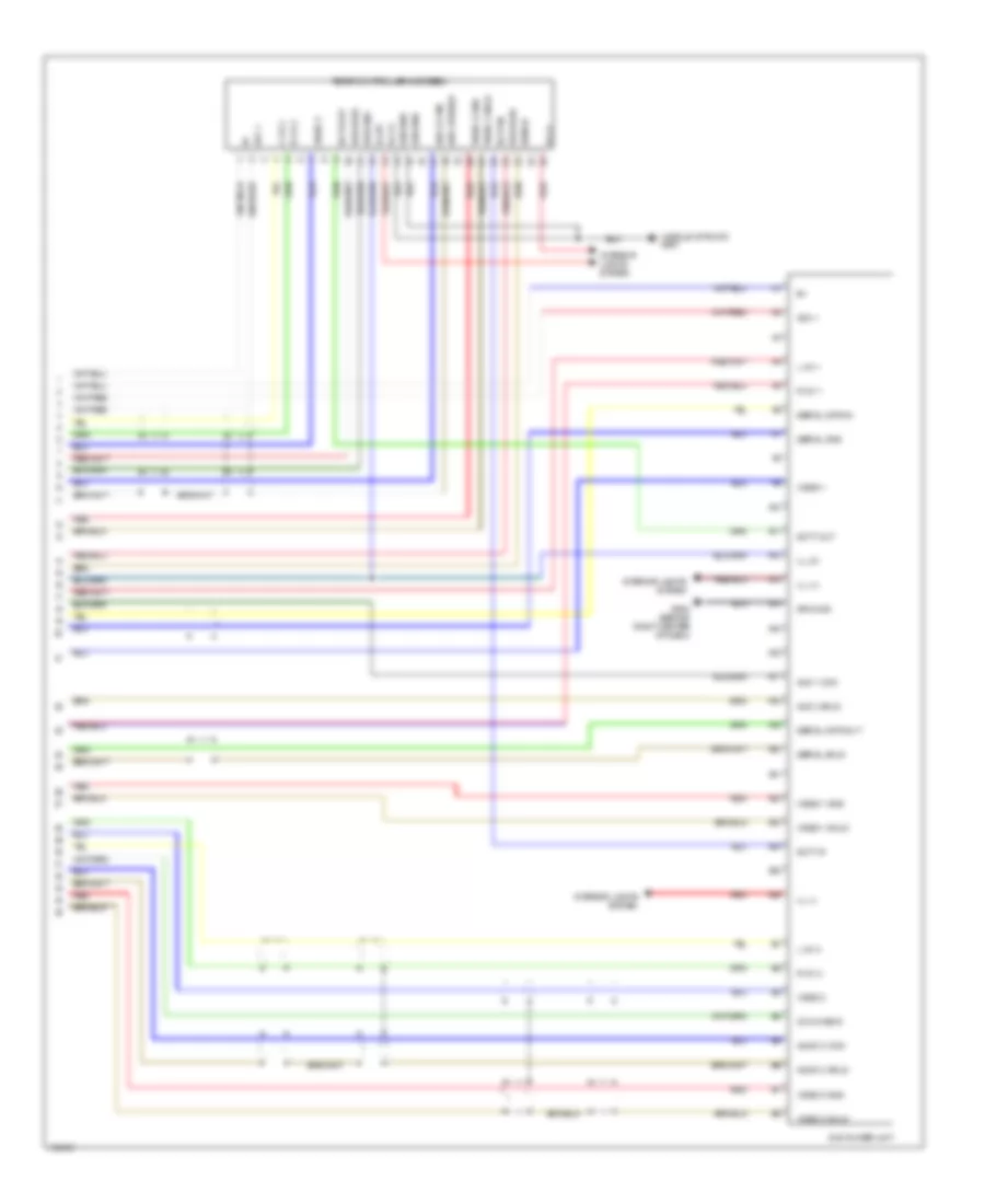 https://portal-diagnostov.com/license.html
Automotive Electricians Portal FZCO
Automotive Electricians Portal FZCO
https://portal-diagnostov.com/license.html
https://portal-diagnostov.com/license.html
Automotive Electricians Portal FZCO
Automotive Electricians Portal FZCOList of elements for Rear Seat Entertainment Wiring Diagram, with Bose System (2 of 2) for Acura MDX 2004:
- (middle of roof) g551
- A10
- A11
- A12
- A13
- A14
- A15
- A16
- A17
- A18
- A19
- A20
- A21
- A22
- A23
- A24
- A25
- A26
- Acc +
- Aud 1 com
- Aud 2 com
- Aud 2 shield
- Aud 3 shld
- Audio 3 com
- Audio 3 shld
- Bus data
- Bus gnd
- Com check
- Dvd player unit
- G502 (behind right center of dash)
- Ground
- Ill (+)
- Ill (-)
- Ill 8v
- Interior lights system
- L ch 1
- L ch 2
- L ch 3
- R ch 1
- R ch 2
- R ch 3
- Rear controller & screen
- Red
- Scty in
- Scty out
- Serial data in
- Serial data out
- Serial gnd
- Serial shld
- Shield
- Video 1
- Video 1 gnd
- Video 1 shld
- Video 2
- Video 2 gnd
- Video 2 shld
- Video 3
- Video 3 gnd
- Video 3 shld
SHIFT INTERLOCK
Shift Interlock Wiring Diagram for Acura MDX 2004
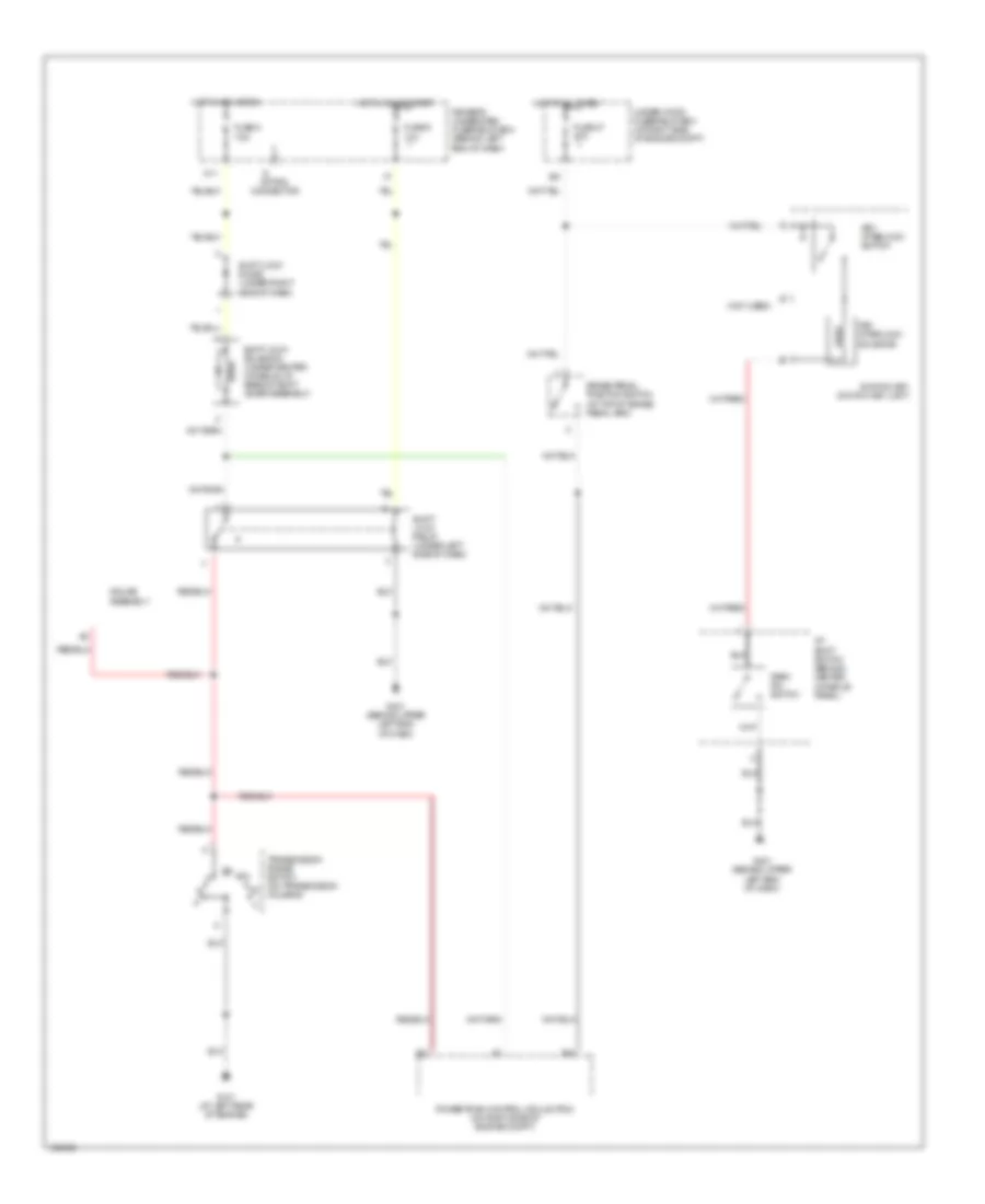 https://portal-diagnostov.com/license.html
Automotive Electricians Portal FZCO
Automotive Electricians Portal FZCO
https://portal-diagnostov.com/license.html
https://portal-diagnostov.com/license.html
Automotive Electricians Portal FZCO
Automotive Electricians Portal FZCOList of elements for Shift Interlock Wiring Diagram for Acura MDX 2004:
- (not used)
- A/t shift switch (behind center console panel)
- B21
- B39
- Brake pedal position switch (at top of brake pedal arm)
- Driver's underdash fuse/relay box (behind left end of dash)
- Fuse 47 20a
- Fuse 8 7.5a
- Fuse 9 10a
- G101 (at left rear of engine)
- G401 (behind upper left end of dash)
- Gauge assembly
- Hot at all times
- Hot in acc or on
- Hot in on or start
- Ignition key switch/ key light
- Key interlock solenoid
- Key interlock switch
- M11
- Option connector
- Park pin switch
- Powertrain control mdule (pcm) (on right side of engine compt)
- Shift lock diode (under right side of dash)
- Shift lock relay (under left side of dash)
- Shift lock solenoid (under center console, at base of shift lever assembly)
- Transmission range switch (on transmission housing)
- Under-hood fuse/relay box (at right side of engine compt)
STARTING/CHARGING
Charging Wiring Diagram for Acura MDX 2004
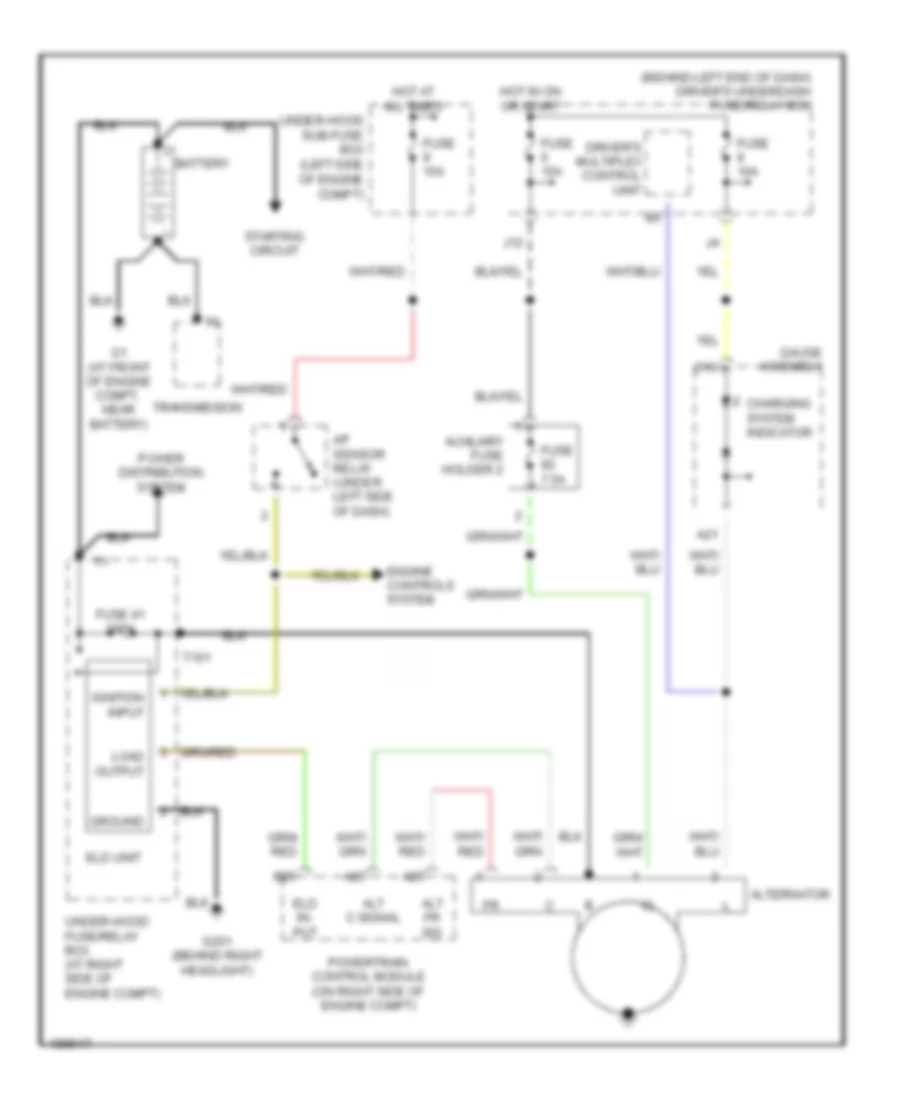 https://portal-diagnostov.com/license.html
Automotive Electricians Portal FZCO
Automotive Electricians Portal FZCO
https://portal-diagnostov.com/license.html
https://portal-diagnostov.com/license.html
Automotive Electricians Portal FZCO
Automotive Electricians Portal FZCOList of elements for Charging Wiring Diagram for Acura MDX 2004:
- (behind left end of dash) driver's underdash fuse/relay box
- A/f sensor relay (under left side of dash)
- A21
- A23
- A25
- Alt c signal
- Alt fr sig
- Alternator
- Auxiliary fuse holder 2
- B25
- Battery
- C10
- Charging system indicator
- Driver's multiplex control unit
- Eld in- put
- Eld unit
- Engine controls system
- Fuse 10a
- Fuse 15a
- Fuse 41 120a
- Fuse 7.5a
- G1 (at front of engine compt, near battery)
- G201 (behind right headlight)
- Gauge assembly
- Ground
- Hot at all times
- Hot in on or start
- Ignition input
- J12
- Load output
- Power distribution system
- Powertrain control module (on right side of engine compt)
- Starting circuit
- T101
- Transmission
- Under-hood fuse/relay box (at right side of engine compt)
- Under-hood sub-fuse box (left side of engine compt)
Starting Wiring Diagram for Acura MDX 2004
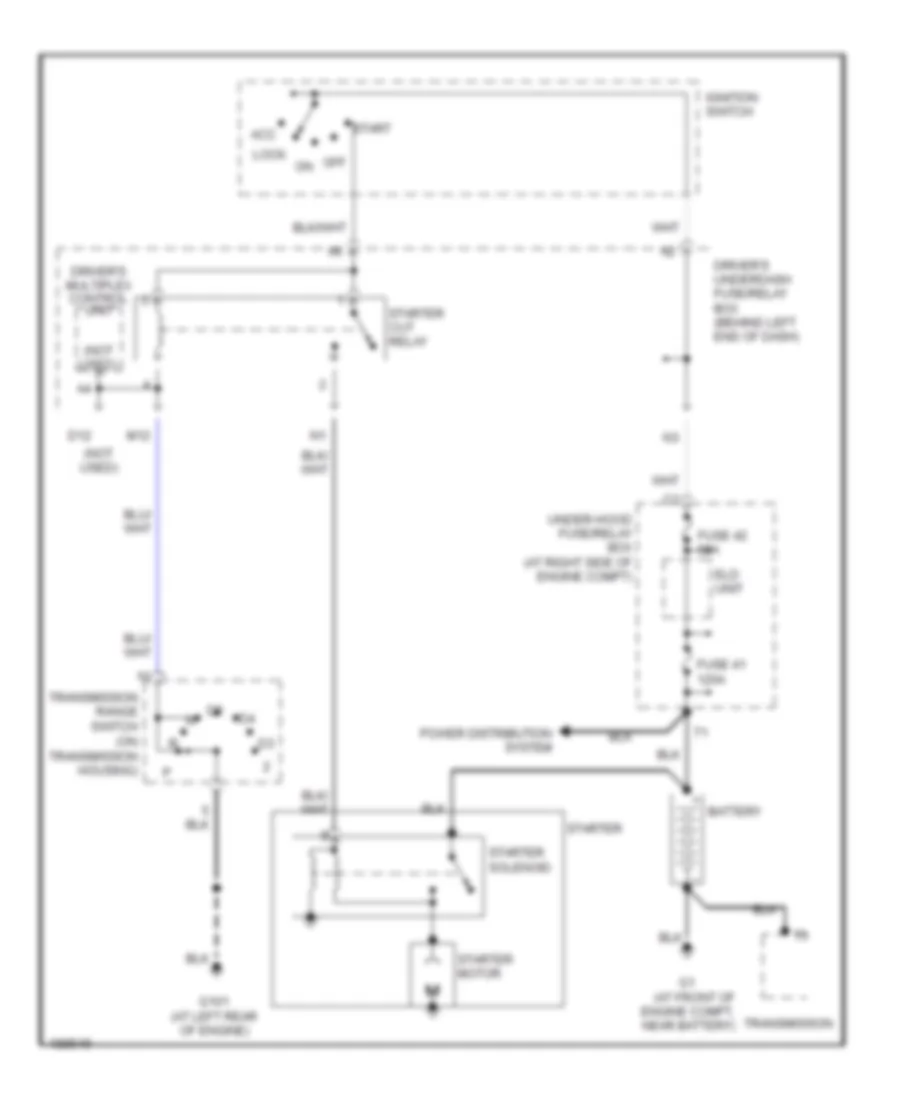 https://portal-diagnostov.com/license.html
Automotive Electricians Portal FZCO
Automotive Electricians Portal FZCO
https://portal-diagnostov.com/license.html
https://portal-diagnostov.com/license.html
Automotive Electricians Portal FZCO
Automotive Electricians Portal FZCOList of elements for Starting Wiring Diagram for Acura MDX 2004:
- (at front of engine compt, transmission near battery)
- (not used)
- Acc
- Battery
- D12
- Driver's multiplex control unit
- Driver's underdash fuse/relay box (behind left end of dash)
- Eld unit
- Fuse 41 120a
- Fuse 42 50a
- G101 (at left rear of engine)
- Ignition switch
- Lock
- M12
- Off
- Power distribution system
- Start
- Starter
- Starter cut relay
- Starter motor
- Starter solenoid
- Transmission range switch (on transmission housing)
- Under-hood fuse/relay box (at right side of engine compt)
SUPPLEMENTAL RESTRAINTS
Supplemental Restraints Wiring Diagram (1 of 3) for Acura MDX 2004
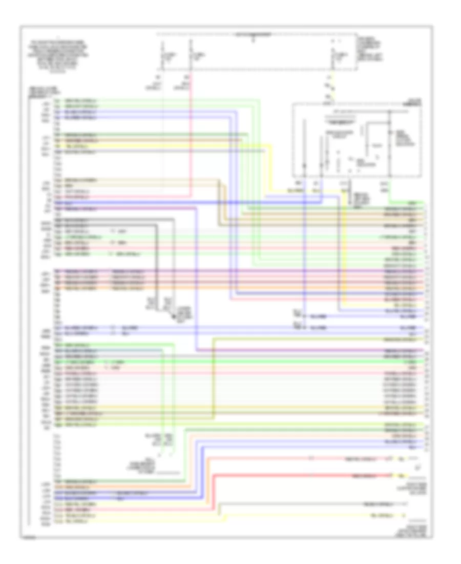 https://portal-diagnostov.com/license.html
Automotive Electricians Portal FZCO
Automotive Electricians Portal FZCO
https://portal-diagnostov.com/license.html
https://portal-diagnostov.com/license.html
Automotive Electricians Portal FZCO
Automotive Electricians Portal FZCOList of elements for Supplemental Restraints Wiring Diagram (1 of 3) for Acura MDX 2004:
- (behind left end of dash) g501
- (behind lower center of dash) srs unit
- (under center of dash) g801
- A10
- A11
- A12
- A13
- A14
- A15
- A16
- A17
- A18
- A19
- A20
- A21
- A22
- A23
- A24
- A25
- A26
- A27
- A28
- B10
- B11
- B12
- B13
- B14
- B15
- B16
- B17
- B18
- B19
- B20
- B21
- B22
- B23
- B24
- B25
- B26
- B27
- B28
- C10
- C11
- C12
- C13
- C14
- C15
- C16
- Driver's underdash fuse/relay box (behind left end of dash)
- Fuse 1 15a
- Fuse 2 10a
- Fuse 9 10a
- Gauge assembly
- Gnda
- Gndb
- Hot in on or start
- La1 +
- La1 -
- La2 +
- La2 -
- Lbsc
- Lbsd
- Lca+
- Lca-
- Lcsi+
- Lcsi-
- Lfs +
- Lfs -
- Lrp +
- Lrp -
- Lsa +
- Lsa -
- Lsi +
- Lsi -
- Main circuit
- Mes
- Odus
- Pin shorting bars engaged when module is disconnected from harness connector (shorting bars are connected between pins :a9-a10, a3-a4, b21-b22, b23-b24, a1-a2, a7-a8, c11-c12, c13-c14)
- Ptt
- Ra1 +
- Ra1 -
- Ra2 +
- Ra2 -
- Rbsc
- Rbsd
- Rca+
- Rca-
- Rcsi+
- Rcsi-
- Red
- Rfs +
- Rfs -
- Right side curtain air bag inflator
- Right side impact sensor (right "b" pillar)
- Roll rate sensor (under middle of dash)
- Rrp +
- Rrp -
- Rrs+
- Rrs-1
- Rsa +
- Rsa -
- Rsi +
- Rsi -
- Scs
- Side airbag cut-off indicator
- Srs indicator
- Srs indicator circuit
- Ss +
- Ss -
Supplemental Restraints Wiring Diagram (2 of 3) for Acura MDX 2004
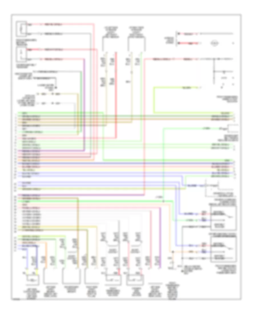 https://portal-diagnostov.com/license.html
Automotive Electricians Portal FZCO
Automotive Electricians Portal FZCO
https://portal-diagnostov.com/license.html
https://portal-diagnostov.com/license.html
Automotive Electricians Portal FZCO
Automotive Electricians Portal FZCOList of elements for Supplemental Restraints Wiring Diagram (2 of 3) for Acura MDX 2004:
- (at left side of engine compt) left front impact sensor
- (at right side of engine compt) right front impact sensor
- (under center of dash) g801
- A18
- Data link connector (lower left side of dash, behind lower cover)
- Driver's multiplex control unit
- Driver's seat belt switch (under driver's seat)
- Driver's seat belt tension reducer solenoid
- Driver's seat belt tensioner
- Driver's seat position sensor
- Driver's side air bag inflator
- Driver's underdash fuse/relay box (behind left end of dash)
- Front passenger's airbag cutoff indicator
- Front passenger's seat belt switch (under front passenger's seat)
- Front passenger's seat belt tension reducer solenoid (right "b" pillar)
- Front passenger's seat belt tensioner
- Front passenger's side air bag inflator
- Interior lights system
- K12
- Left side curtain air bag inflator (left side of roof)
- Left side impact sensor (behind left rear lining)
- Mes connector (under left side of dash)
- Red
- Right side impact sensor (right "b" pillar)
- Seat belt buckled
- Seat belt unbuckled
- Short contact
Supplemental Restraints Wiring Diagram (3 of 3) for Acura MDX 2004
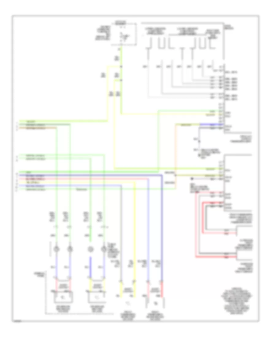 https://portal-diagnostov.com/license.html
Automotive Electricians Portal FZCO
Automotive Electricians Portal FZCO
https://portal-diagnostov.com/license.html
https://portal-diagnostov.com/license.html
Automotive Electricians Portal FZCO
Automotive Electricians Portal FZCOList of elements for Supplemental Restraints Wiring Diagram (3 of 3) for Acura MDX 2004:
- (below center console, behind shifter) g631
- (lower 4 sensors in seat back) lower element
- (right side of seat back) side element
- (upper 2 sensors in seat back) upper element
- Cable reel (behind steering column cover)
- Driver's air bag first inflator
- Driver's air bag second inflator
- Driver's underdash fuse/relay box (behind left end of dash)
- Front passenger's air bag first inflator
- Front passenger's air bag second inflator
- Front passenger's weight sensor unit (under front passenger's seat)
- Fuse 7 7.5a
- G631 (below center console, behind shifter)
- Gnd
- Hot in on or start
- Inner side front passenger's weight sensor
- Odus
- Opds sensor
- Opds unit (in front passenger's seat)
- Outer side front passenger's weight sensor
- Pow
- Red
- Sb1l, sb1s
- Sb2l, sb2s
- Sb3l, sb3s
- Sb4l, sb4s
- Sb5l, sb5s
- Sb6l, sb6s
- Short contact
- Ss1l, ss1s
- Steering wheel
- Swig
- Swip
- Swog
- Swop
- Warning: to avoid accidental deployment & possible injury, always disconnect driver's air bag, front passenger's air bag connectors (which automatically shorts them) before working near any srs wiring
- Wrn
TRANSMISSION
4WD Wiring Diagram for Acura MDX 2004
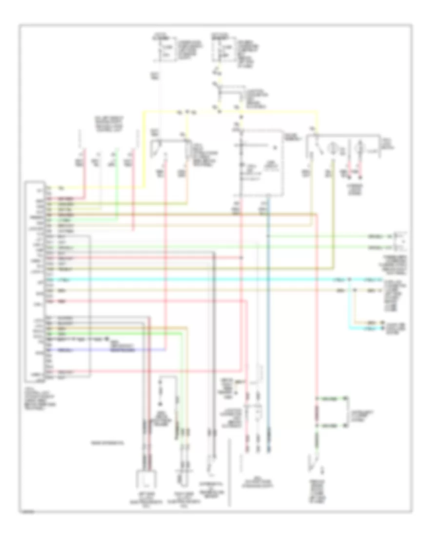 https://portal-diagnostov.com/license.html
Automotive Electricians Portal FZCO
Automotive Electricians Portal FZCO
https://portal-diagnostov.com/license.html
https://portal-diagnostov.com/license.html
Automotive Electricians Portal FZCO
Automotive Electricians Portal FZCOList of elements for 4WD Wiring Diagram for Acura MDX 2004:
- (above right rear fender)
- (on left side of engine compt) vsa modulator control unit
- 2a1
- A10
- A11
- A12
- A13
- A14
- A15
- A16
- A17
- A18
- A19
- A20
- A22
- B10
- B11
- B12
- B15
- B16
- B27
- C10
- Can h
- Can l
- Computer data lines system
- Data link connector (lower
- Differential oil temperature sensor
- Driver's underdash fuse/relay box (behind left end of dash)
- Flp
- Frp
- Fsr
- Fuse 10a
- Fuse 20a
- G652
- G652 (above right rear fender)
- Gauge assembly
- Hot at all times
- Hot in on or start
- Ig 1
- Illum
- Instrument cluster system
- Interior lights system
- Junction connector c501 (behind glove box)
- Lcoh
- Lcol
- Left side clutch electromagnetic coil
- Left side of dash, behind lower cover)
- Let
- Lg 1
- Lg 2
- Lock h
- Lock sw
- Main circuit
- Nep
- On ind
- Parbrk
- Parking brake switch (under left side of dash)
- Passenger's underdash fuse/relay box (behind right kick panel)
- Pcm (on right side of engine compt)
- Pwr
- Rcoh
- Rcol
- Rear differential
- Red
- Right side clutch electromagnetic coil
- Rlp
- Rrp
- Scs
- Tch
- Tcl
- Under-hood sub-fuse box (left side of engine compt)
- Vtm-4 control unit (at right side of cargo area, behind rear side trim panel)
- Vtm-4 ind
- Vtm-4 lock switch
- Vtm-4 relay (at right side of cargo area, behind trim panel)
- Warn 1
- Warn 2
A/T Wiring Diagram (1 of 2) for Acura MDX 2004
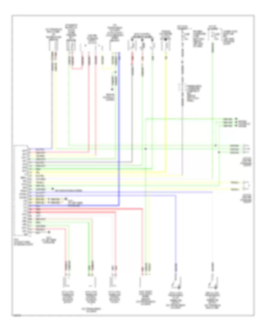 https://portal-diagnostov.com/license.html
Automotive Electricians Portal FZCO
Automotive Electricians Portal FZCO
https://portal-diagnostov.com/license.html
https://portal-diagnostov.com/license.html
Automotive Electricians Portal FZCO
Automotive Electricians Portal FZCOList of elements for A/T Wiring Diagram (1 of 2) for Acura MDX 2004:
- (at rear of engine, on top of water passage) ect sensor
- (center
- (on transaxle end cover) atf temperature sensor
- (on transmission housing)
- (on transmission housing) output shaft (countershaft) speed sensor
- 3rd clutch transmission fluid pressure switch (on transaxle end cover)
- 4th clutch transmission fluid pressure switch (on transmission housing)
- A/t clutch
- Air conditioning system
- Atft
- B10
- Driver's underdash fuse/ relay box (behind left end of dash)
- Ect
- Engine controls system
- Fuse 15a
- Fuse 7.5a
- G101 (at left rear of engine)
- H12
- Hot at all times
- Hot in on or start
- Input shaft (main shaft) speed sensor (on transmission housing)
- J/c c103 (center of engine compt)
- J/c c104 (center of engine compt)
- J12
- Lg1
- Lg2
- Lsa+
- Lsa-
- Lsb+
- Lsb-
- Lsc+
- Lsc-
- Of engine compt) j/c c104
- Op3sw
- Op4sw
- Passenger's underdash fuse/relay box (behind right kick panel)
- Pcm (on right side of engine compt)
- Pdsw
- Pnk
- Pressure control solenoid valve a
- Pressure control solenoid valve b
- Pressure control solenoid valve c
- Red
- Sg1
- Sg2
- Sha
- Shb
- Shc
- Shift control solenoid valves
- Torque converter clutch solenoid
- Under-hood sub-fuse box (left side of engine compt)
- Vbsol
- Vbu
- Vcc1
- Vcc2
A/T Wiring Diagram (2 of 2) for Acura MDX 2004
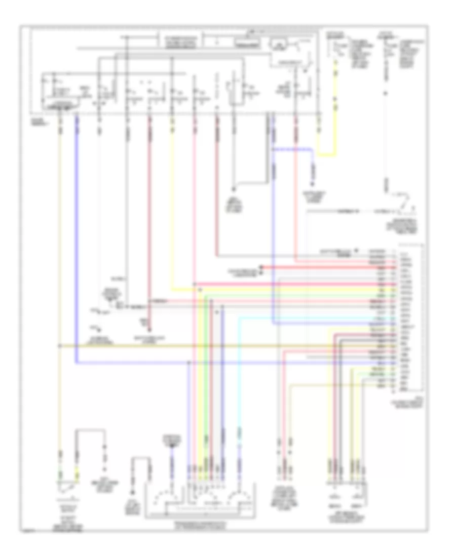 https://portal-diagnostov.com/license.html
Automotive Electricians Portal FZCO
Automotive Electricians Portal FZCO
https://portal-diagnostov.com/license.html
https://portal-diagnostov.com/license.html
Automotive Electricians Portal FZCO
Automotive Electricians Portal FZCOList of elements for A/T Wiring Diagram (2 of 2) for Acura MDX 2004:
- 1st hold switch
- 2 position cancel circuit
- A/t gear position/ cruise control dimming circuit
- A/t shift switch (behind center console panel)
- A/t tempe- rature ind
- A10
- A11
- A12
- A24
- A27
- A28
- App sensor (at right rear side of engine compt)
- Aps1
- Aps2
- Atfind
- Atp d3
- Atp d4
- Atp d5
- Atp f
- Atp n
- Atp p
- Atp r
- Atp2
- Back- up lights
- Bksw
- Brake pedal position switch (at top of brake pedal arm)
- C10
- C12
- C13
- Can h
- Can l
- Computer data lines system
- D5ind
- Data link connector (lower left side of dash, behind lower cover)
- Driver's underdash fuse/ relay box (behind left end of dash)
- Engine controls system
- Exterior lights system
- Fuse 10a
- Fuse 20a
- G101 (at left rear of engine)
- G401 (behind upper left end of dash)
- G501 (behind left end of dash)
- Gauge assembly
- Hot at all times
- Hot in on or start
- Illu
- Instrument cluster system
- K-line
- Led driver
- Lhsw
- Main circuit
- Pcm (on right side of engine compt)
- Pnk
- Red
- Regulator
- Scs
- Sens 1
- Sens 2
- Sg2
- Sg3
- Shift interlock system
- Starting/ charging system
- Transmission range switch (on transmission housing)
- Under-hood fuse/ relay box (at right side of engine compt)
- Vcc3
- Vcc4
- Vssout
- Wen
WARNING SYSTEMS
Chime Wiring Diagram for Acura MDX 2004
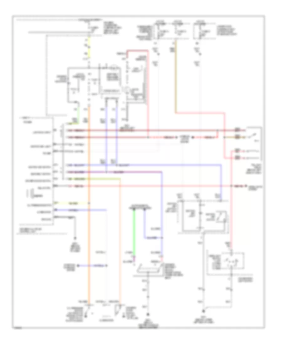 https://portal-diagnostov.com/license.html
Automotive Electricians Portal FZCO
Automotive Electricians Portal FZCO
https://portal-diagnostov.com/license.html
https://portal-diagnostov.com/license.html
Automotive Electricians Portal FZCO
Automotive Electricians Portal FZCOList of elements for Chime Wiring Diagram for Acura MDX 2004:
- 15a
- 20a
- 7.5a
- A12
- A13
- A14
- A15
- A16
- A18
- A22
- A24
- Alternator
- B11
- B17
- B20
- Beeper
- C10
- C13
- Combination light switch
- Drive circuit
- Driver's door indicator
- Driver's door switch
- Driver's door switch (at left ``b" pillar)
- Driver's multiplex control unit
- Driver's seat belt switch (except dpms: under driver's seat)
- Driver's underdash fuse/relay box (behind left end of dash)
- Fuse 10
- Fuse 13
- Fuse 47
- Fuse 9 10a
- G401 (behind upper left end of dash)
- G501 (behind left end of dash)
- G631 (below center console, behind shifter)
- Gauge assembly
- Ground
- Headlight switch 1) off 2) park 3) auto 4) head
- Headlights system
- Hot at all times
- Hot in on or start
- I12
- Ignition key light
- Ignition key switch
- Ignition key switch/ key light
- Interior lights system
- K12
- K16
- Lights on indicator
- Lights on input
- Low oil pressure ind
- M19
- Main circuit
- Oil pressure switch
- Oil pressure switch (on front of engine, at top right of oil pump housing)
- Passenger's underdash fuse/relay box (behind right kick panel)
- Power
- Relay ctrl
- Seat belt reminder indicator
- Seat belt switch
- Starting/ charging system
- Taillight relay (behind left side of dash)
- Under-hood fuse/relay box (at right side of engine compt)
Tire Pressure Monitoring Wiring Diagram for Acura MDX 2004
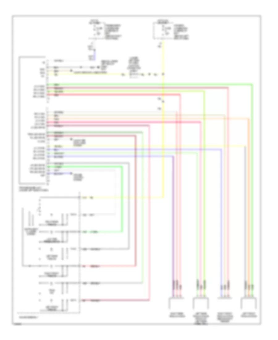 https://portal-diagnostov.com/license.html
Automotive Electricians Portal FZCO
Automotive Electricians Portal FZCO
https://portal-diagnostov.com/license.html
https://portal-diagnostov.com/license.html
Automotive Electricians Portal FZCO
Automotive Electricians Portal FZCOList of elements for Tire Pressure Monitoring Wiring Diagram for Acura MDX 2004:
- (behind upper left end of dash) g401
- (under left side of dash) junction connector c404
- A16
- A23
- A25
- A29
- C10
- Computer data lines system
- Cruise control system
- Driver's underdash fuse/relay box (behind left end of dash)
- Fuse 10a
- Gauge assembly
- Gnd
- Hot at all times
- Hot in on or start
- Ig1
- Instrument cluster system
- K-line
- Left front tire ind
- Left front tpms initiator
- Left rear tire ind
- Left rear tpms initiator (front of left rear wheelwell)
- Lf led drive
- Lf lf gnd
- Lf lf pwr
- Lf lf sig
- Low tire pressure ind
- Lr led drive
- Lr lf pwr
- Lr lf sig
- Ltp led drive
- Passenger's underdash fuse/relay box (behind right kick panel)
- Pnk
- Red
- Rf lf gnd
- Rf lf grd
- Rf lf pwr
- Rf lf sig
- Right front tire ind
- Right front tpms initiator (behind right fender)
- Right rear tire ind
- Right rear tpms initiator
- Rl led drive
- Rr led drive
- Rr lf grd
- Rr lf pwr
- Rr lf sig
- Scs
- Tpms ind
- Tpms led drive
- Tpms receiver unit (under left side of dash)
- Vsp
WIPER/WASHER
Front Wiper/Washer Wiring Diagram, with Auto Wiper System (1 of 2) for Acura MDX 2004
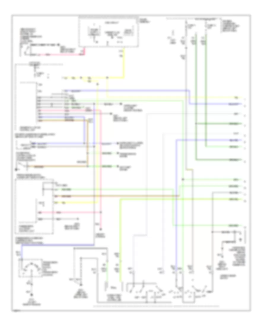 https://portal-diagnostov.com/license.html
Automotive Electricians Portal FZCO
Automotive Electricians Portal FZCO
https://portal-diagnostov.com/license.html
https://portal-diagnostov.com/license.html
Automotive Electricians Portal FZCO
Automotive Electricians Portal FZCOList of elements for Front Wiper/Washer Wiring Diagram, with Auto Wiper System (1 of 2) for Acura MDX 2004:
- (behind right side of front bumper, on washer reservoir) washer fluid level switch
- (not used)
- A11
- A21
- A22
- A23
- A24
- Anti-theft system
- Atp p
- Auto
- B11
- B14
- B15
- B22
- B26
- C10
- D11
- D20
- Drive circuit
- Driver's multiplex control unit
- Driver's underdash fuse/relay box (behind left end of dash)
- Fuse 11 10a
- Fuse 12 30a
- Fuse 9 10a
- G101 (at left rear of engine)
- G201 (behind right headlight)
- G401 (behind upper left end of dash)
- G501 (behind left end of dash)
- G503 (behind right end of dash)
- Gauge assembly
- Hot in on or start
- Instrument cluster, air conditioning & seats systems
- Instrument cluster, memory systems
- Intermittent dwell time controller
- J5 (not used)
- K10
- L18
- Main circuit
- Memory systems
- Mist
- Off
- Parking brake switch (under left side of dash)
- Passenger's multiplex control unit
- Passenger's underdash fuse/relay box (behind right kick panel)
- Pnk
- Powertrain control module (on right side of engine compt)
- Transmission range switch (on transmission housing)
- Transmissions system
- Vss out
- Wash
- Washer fluid level ind
- Windshield washer motor (behind right side of front bumper, on washer reservoir)
- Wiper/washer switch
Front Wiper/Washer Wiring Diagram, with Auto Wiper System (2 of 2) for Acura MDX 2004
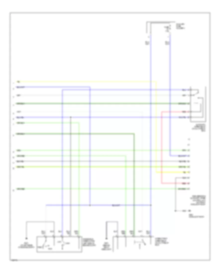 https://portal-diagnostov.com/license.html
Automotive Electricians Portal FZCO
Automotive Electricians Portal FZCO
https://portal-diagnostov.com/license.html
https://portal-diagnostov.com/license.html
Automotive Electricians Portal FZCO
Automotive Electricians Portal FZCOList of elements for Front Wiper/Washer Wiring Diagram, with Auto Wiper System (2 of 2) for Acura MDX 2004:
- Automatic wiper relay (in multi-relay box)
- Auxiliary fuse holder 3
- Fuse 7.5a
- G201 (behind right headlight)
- G301 (at left rear of engine compt)
- G551 (middle of roof)
- High
- Intermittent wiper relay (in multi-relay box)
- Low
- Park
- Rain sensor & automatic wiper control unit (on front middle of roof)
- Red
- Run
- Windshield wiper motor (left side of engine compt)
Front Wiper/Washer Wiring Diagram, without Auto Wiper System for Acura MDX 2004
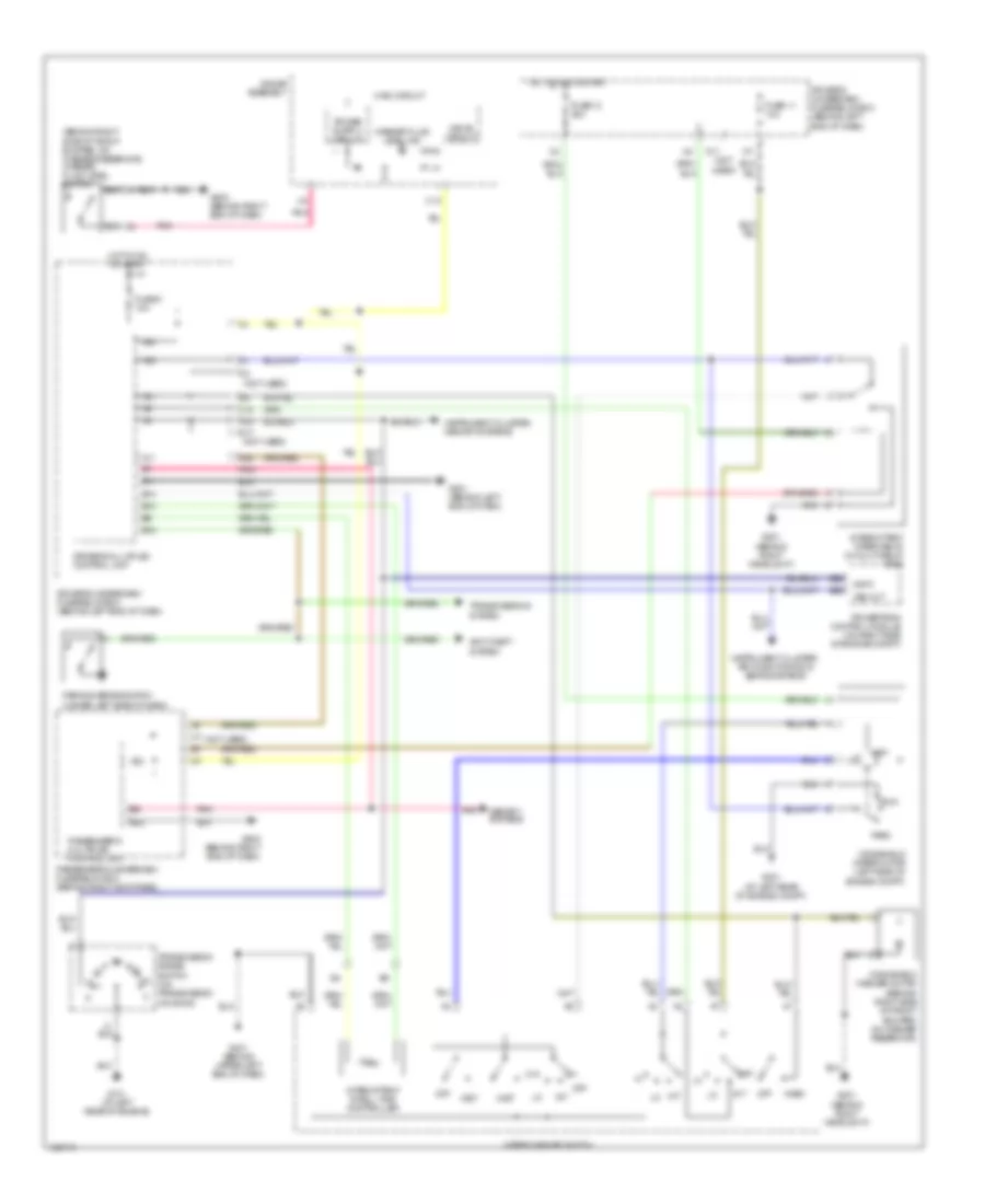 https://portal-diagnostov.com/license.html
Automotive Electricians Portal FZCO
Automotive Electricians Portal FZCO
https://portal-diagnostov.com/license.html
https://portal-diagnostov.com/license.html
Automotive Electricians Portal FZCO
Automotive Electricians Portal FZCOList of elements for Front Wiper/Washer Wiring Diagram, without Auto Wiper System for Acura MDX 2004:
- (behind right side of front bumper, on washer reservoir) washer fluid level switch
- (not used)
- A11
- A21
- A22
- A23
- A24
- Anti-theft system
- Atp p
- B10
- B11
- B14
- B15
- B22
- B26
- C10
- D11 (not used)
- D17
- D20
- Drive circuit
- Driver's multiplex control unit
- Driver's underdash fuse/relay box (behind left end of dash)
- Fuse 11 10a
- Fuse 12 30a
- Fuse 9 10a
- G101 (at left rear of engine)
- G201 (behind right headlight)
- G301 (at left rear of engine compt)
- G401 (behind upper left end of dash)
- G501 (behind left end of dash)
- G503 (behind right end of dash)
- Gauge assembly
- High
- Hot in on or start
- Instrument cluster, air conditioning & seats systems
- Instrument cluster, memory systems
- Int
- Intermittent dwell time controller
- Intermittent wiper relay (in multi-relay box)
- K10
- L18
- Main circuit
- Memory systems
- Mist
- Off
- Park
- Parking brake switch (under left side of dash)
- Passenger's multiplex control unit
- Passenger's underdash fuse/relay box (behind right kick panel)
- Pnk
- Powertrain control module (on right side of engine compt)
- Run
- Transmission range switch (on transmission housing)
- Transmissions system
- Vss out
- Wash
- Washer fluid level ind
- Windshield washer motor (behind right side of front bumper, on washer reservoir)
- Windshield wiper motor (left side of engine compt)
- Wiper/washer switch
Rear Wiper/Washer Wiring Diagram for Acura MDX 2004
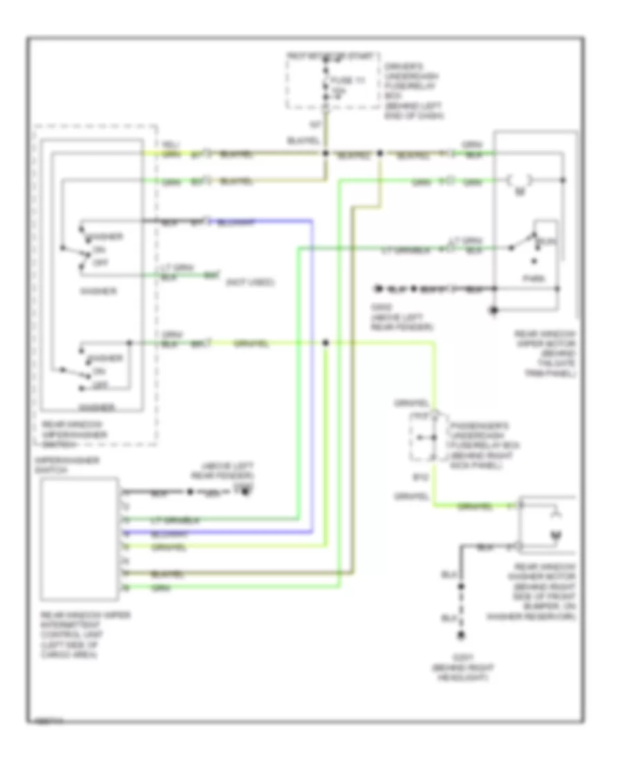 https://portal-diagnostov.com/license.html
Automotive Electricians Portal FZCO
Automotive Electricians Portal FZCO
https://portal-diagnostov.com/license.html
https://portal-diagnostov.com/license.html
Automotive Electricians Portal FZCO
Automotive Electricians Portal FZCOList of elements for Rear Wiper/Washer Wiring Diagram for Acura MDX 2004:
- (above left rear fender) g602
- (not used)
- B12
- Driver's underdash fuse/relay box (behind left end of dash)
- Fuse 11 10a
- G201 (behind right headlight)
- G602 (above left rear fender)
- Hot in on or start
- I13
- Off
- Park
- Passenger's underdash fuse/relay box (behind right kick panel)
- Rear window washer motor (behind right side of front bumper, on washer reservoir)
- Rear window wiper intermittent control unit (left side of cargo area)
- Rear window wiper motor (behind tailgate trim panel)
- Rear window wiper/washer switch
- Run
- Washer
- Wiper/washer switch

 Čeština
 Dansk
Dansk Deutsch
 Ελληνικά
 English
 English
 Español
 Suomi
Suomi Français
 Français
 עברית
עברית Hrvatski
 Magyar
 Italiano
 한국어
한국어 Nederlands
 Polski
 Português
 Português
 Română
 Русский
 Slovenčina
 Slovenščina
 Svenska
 Türkçe
 中文 (中国)
