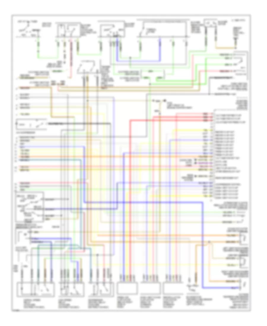
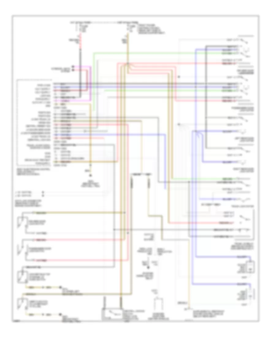
AIR CONDITIONING Air Conditioning Wiring Diagrams (1 of 2) for BMW 325i 1994 https://portal-diagnostov.com/license.html
https://portal-diagnostov.com/license.html
Automotive Electricians Portal FZCO
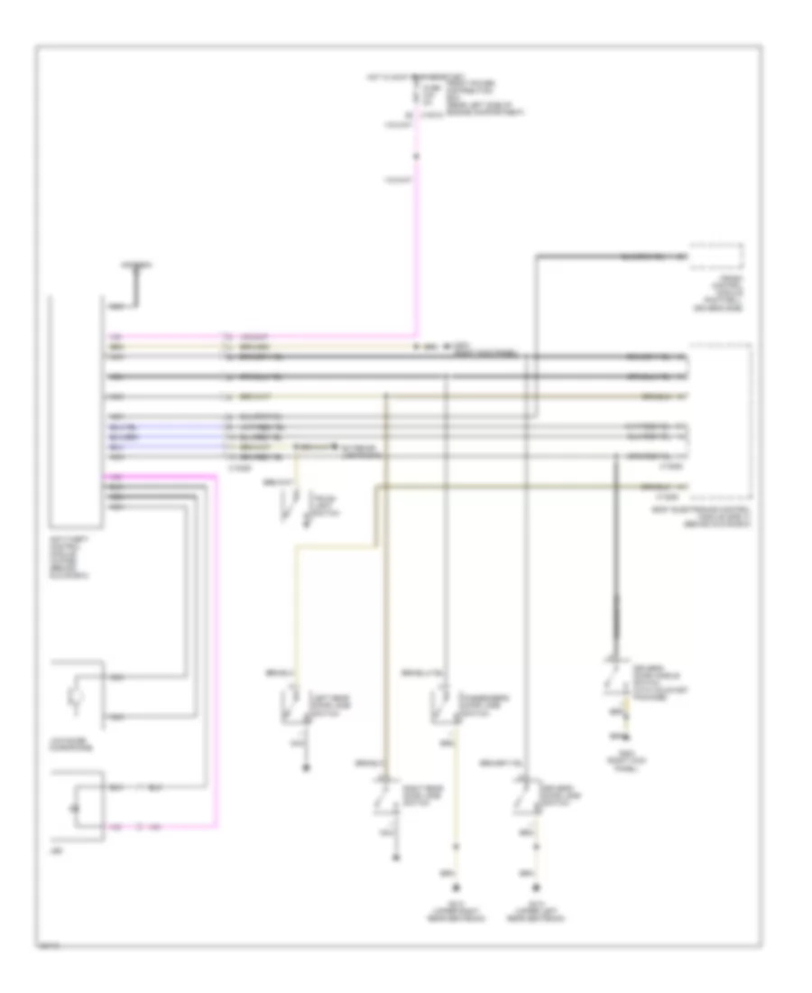
Automotive Electricians Portal FZCO List of elements for Air Conditioning Wiring Diagrams (1 of 2) for BMW 325i 1994: (1994) (1995) (behind right footwell trim) (or 1994-95 1995 318i A/c switch Air circulation sw Auxiliary fuse box Battery C 1995 vftc Charging system Circulation switch Ckp/rpm signal Control panel Defog switch Ecm Electric flaps switch Engine control module (dme) (right rear side of engine compartment) Evap temp Except Front power distri- bution box Function ligh-rear defog Function light-a/c Function light-recirc Fuse 30a Fuse 40a Fuse 5a Fuse 7.5a G203 G203 (behind right footwell trim) Generator signal Ground Heater temp-left Heater temp-right Hot at all times Hot in accy run or start Hot in run or start Ignition Illumination Independent ventilation Instrument cluster Integrated climate regulation control module (above center console) Interior lights system Interior temp sensor Left rotary temp switch Left water valve Max heat switch Mix actuator Nca Nominal air flow valve Nominal temp valve-left Nominal temp valve-right Outside temp Park/heat vent sig Rear defog sw Right rotary temp switch Right water valve Rotary blower switch Sensor blower Starter signal Starting system Transmission controls system Variable camshaft control module (right rear of engine compt) Vehicle speed Voltage for func lights Voltage for mix act Water valve assembly
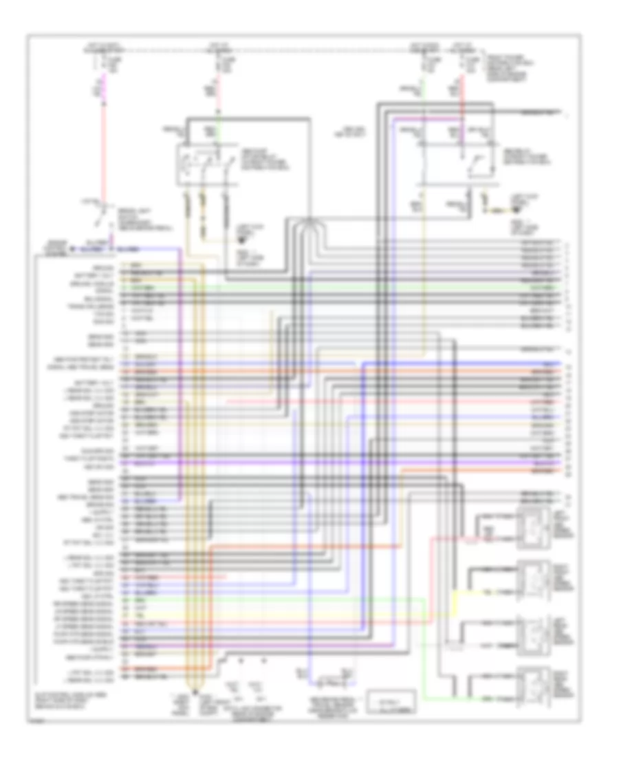
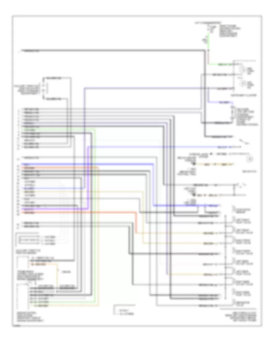
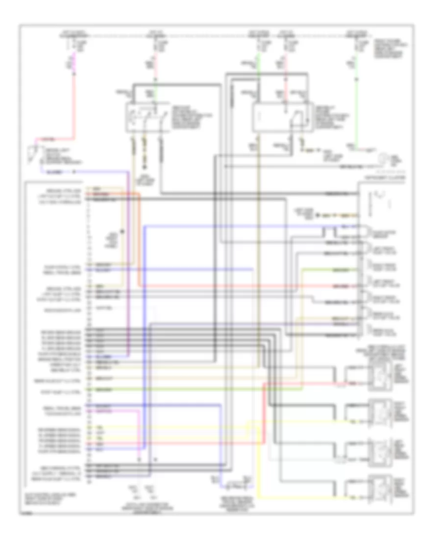
Air Conditioning Wiring Diagrams (2 of 2) for BMW 325i 1994 https://portal-diagnostov.com/license.html
https://portal-diagnostov.com/license.html
Automotive Electricians Portal FZCO
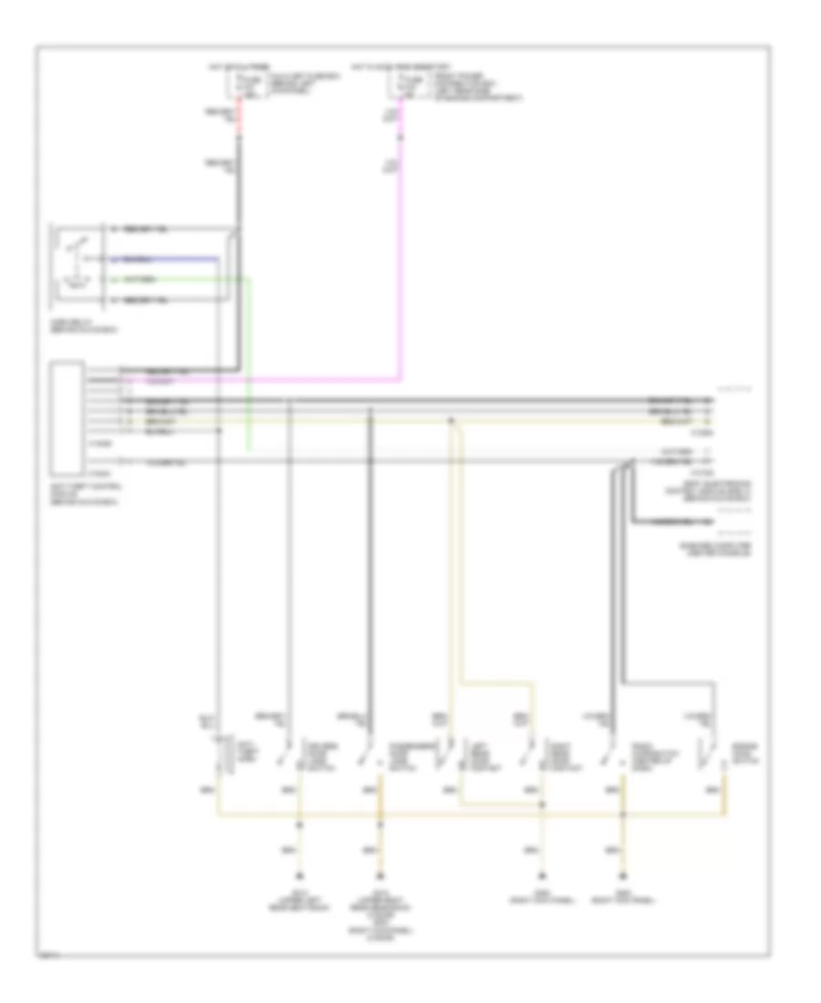
Automotive Electricians Portal FZCO すべての配線図にアクセスする車 List of elements for Air Conditioning Wiring Diagrams (2 of 2) for BMW 325i 1994: (behind right footwell trim) (footwell, driver's side) 1994-95 A/c compressor Above 18 bar Above 2.6 bar Above 30 bar Acc And Auxiliary fan motor Behind right Below 1.5 bar Below 15 bar Below 21 bar Blower motor Blower relay (in power distribution box) Blower resistors (behind center of dash) Blower switch C 1995 vftc Compressor control Compressor control relay (in power distribution box) Computer data lines Dash vent mix flap Dash vent mixing flap motor (right of steering column) Data line Evaporator temperature sensor (right side of left footwell) Fresh air cowl) Fresh air flap motor (below right side of dash) Fresh flap act G100 (left front of engine compartment) G202 (below left side of dash) G203 High speed relay (in power distribution box) Hot at all times Ignition switch Integrated climate regulation control module (above center console) Inter sens blow act Left heat exchanger temperature sensor (1993-94) (center console) Max Mixing actuator (center console) Nca Normal speed relay (in power distribution box) Off On-board computer (center console) Outside temperature sensor (rear of engine compartment Park heating/ ventilation relay box Pressure switch (rear right headlight) Rear defogger act Rear defogger system Recirc flap act Recirculation flap motor (right of steering column) Red Red/ w/ park heating ventilation Right heat exchanger temperature sensor (center console) Run Start Temper- ature switch (right top of radiator) 1) above 99 deg c 2) above 91 deg c Thermal limiter Vent flap switch Volatage for fresh flap Voltage for mix flap Voltage for rec flap Voltage for rot sw W/ park heating ventilation W/o park heating ventilation
ANTI-LOCK BRAKES Anti-lock Brake Wiring Diagrams, with Traction Control (1 of 2) for BMW 325i 1994 https://portal-diagnostov.com/license.html
https://portal-diagnostov.com/license.html
Automotive Electricians Portal FZCO
Automotive Electricians Portal FZCO すべての配線図にアクセスする車 List of elements for Anti-lock Brake Wiring Diagrams, with Traction Control (1 of 2) for BMW 325i 1994: (left kick panel) g200 1994 325i, 1997 z3 only Abs brake pedal travel sensor (near brake fluid reservoir) Abs lp ctrl Abs pump motor relay (in front power distribution box) Abs pump mtr rly Abs pwr protect rly Abs relay (in front power distribution box) Abs travel sens sig Ads step motor All others ** Asc lp ctrl Asc sw sig Asc throt flap pot Battery volt Brake light switch (on bracket, above brake pedal) Brake sig Data link connector (rear of engine compartment) Eml-signal Engine control system Front power distribution box (rear left side of engine compartment) Fuse f10 30a Fuse f21 5a Fuse f38 30a Fuse f46 15a G108 (left front of eng compt) G202 (left side of dash) G203 (right kick panel) Ground Ground, module Hot at all times Hot in accy, run and start Hot in run and start Idle spd sig Ign sig L fnt sol vlv sig L rear sol vlv sig Left front abs speed sensor Left rear abs speed sensor Lf speed sens signal Lr speed sens signal Nca Pump mtr sens shield Pump mtr sens signal Rf speed sens signal Right front abs speed sensor Right rear abs speed sensor Rr speed sens signal Rt fnt sol vlv sig Rxd sig Sens gnd Signal Signal abs travel sens Slip control module (abs) (right side of dash, behind glove box) Sol vlv Spd sig Throt flap postn Trans influence Txd sig Z3 only *
Anti-lock Brake Wiring Diagrams, with Traction Control (2 of 2) for BMW 325i 1994 https://portal-diagnostov.com/license.html
https://portal-diagnostov.com/license.html
Automotive Electricians Portal FZCO
Automotive Electricians Portal FZCO すべての配線図にアクセスする車 List of elements for Anti-lock Brake Wiring Diagrams, with Traction Control (2 of 2) for BMW 325i 1994: (1994-95) (1996-97 328i, m3) (below center console) g302 (left kick panel) g200 * ** Abs hydraulic unit (rear left side of engine compartment behind left shock tower) Abs warn ind All others ** Asc diode (top left side of engine compartment, in front of power distribution box) Asc switch Asc warn ind Auxiliary throttle position motor (front of engine compartment) Auxiliary throttle position sensor Engine control module (dme) (rear right side of engine compartment) Front power distribution box (rear left side of engine compartment) Fuse f27 5a G202 (left side of dash) G203 (behind right footwell trim) Hot in run and start Instrument cluster Interior lights system Left front inlet valve Left front outlet valve Left rear inlet valve Left rear outlet valve Nca Pump motor sensor Right front inlet valve Right front outlet valve Right rear inlet valve Right rear outlet valve Separator valve Transmission control module (egs) (right rear side of engine compartment) Z3 only *
Anti-lock Brake Wiring Diagrams, without Traction Control for BMW 325i 1994 https://portal-diagnostov.com/license.html
https://portal-diagnostov.com/license.html
Automotive Electricians Portal FZCO
Automotive Electricians Portal FZCO すべての配線図にアクセスする車 List of elements for Anti-lock Brake Wiring Diagrams, without Traction Control for BMW 325i 1994: (left side of dash) g202 Abs brake pedal travel sensor (near brake fluid reservoir) Abs hydraulic unit (rear left side of engine compartment behind left shock tower) Abs pump motor relay (power distribution box) (rear left side of engine compartment) Abs relay (power distribution box) (rear left side of engine compartment) Abs relay ctrl Abs warn ind Abs warning lp ctrl Brake light switch (brake pedal support bracket) Brake pedal position Data link connector (rear right side of engine compartment) Fl spd sens ground Fl speed sens signal Fr spd sens ground Fr speed sens signal Front power distribution box (rear left side of engine compartment) Fuse f10 30a Fuse f21 5a Fuse f27 5a Fuse f38 30a Fuse f46 30a G202 (left side of dash) G203 (right kick panel) Ground, ctrl mod Hot at all times Hot in accy, run and start Hot in run and start Instrument cluster L fnt inlet vlv ctrl L fnt outlet vlv ctrl Left front abs speed sensor Left front inlet valve Left front outlet valve Left rear abs speed sensor Nca Operating volt Pedal travel sens Pump motor sensor Pump mtr rly ctrl Pump mtr sens shield Pump mtr sens signal R fnt inlet vlv ctrl R fnt outlet vlv ctrl Rear axle inlet valve Rear axle inlet vlv ctrl Rear axle out vlv ctrl Rear axle outlet valve Red Right front abs speed sensor Right front inlet valve Right front outlet valve Right rear abs speed sensor Rl spd sens ground Rl speed sens signal Rr spd sens ground Rr speed sens signal Rxd diag data link Slip control module (abs) (right side of dash, behind glove box) Txd diag data link Volt mon, hydraulics
ANTI-THEFT Anti-theft Wiring Diagram, Early Production for BMW 325i 1994 https://portal-diagnostov.com/license.html
https://portal-diagnostov.com/license.html
Automotive Electricians Portal FZCO
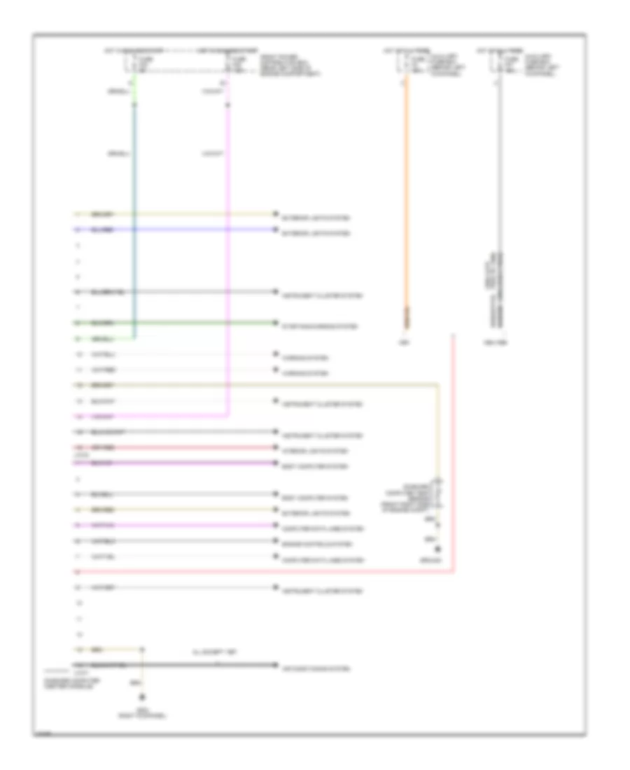
Automotive Electricians Portal FZCO すべての配線図にアクセスする車 List of elements for Anti-theft Wiring Diagram, Early Production for BMW 325i 1994: Antenna Anti-theft control module (alpine) (behind glove box) Body electronics control module (zke iv) (behind glove box) Crash control module (footwell, driver's side) Driver's door handle switch (with cold/wet package) Driver's door jamb switch Exterior lights sys Front power distribution box (rear left side of engine compartment) Fuse f43 5a G203 (right kick panel) G310 (upper right rear seatback) G312 (upper left rear seatback) Hot in accy, run and start Led Left rear door jamb switch Low-noise microphone Nca Passenger's door jamb switch Right rear door jamb switch Trunk light switch X10018 X13025 X13254
Anti-theft Wiring Diagram, Late Production for BMW 325i 1994 https://portal-diagnostov.com/license.html
https://portal-diagnostov.com/license.html
Automotive Electricians Portal FZCO
Automotive Electricians Portal FZCO すべての配線図にアクセスする車 List of elements for Anti-theft Wiring Diagram, Late Production for BMW 325i 1994: Anti- theft horn Anti-theft control module (behind glove box) Auxiliary fuse box (behind left kickpanel) Body electronics control module (zke iv) (behind glove box) Drivers door jamb switch Engine hood switch Front power distribution box (left rear side of engine compartment) Fuse f43 5a Fuse f47 15a G200 (right kick panel) G310 (upper right rear sear back) (4 door) g203 (right kick panel) (2 door) G312 (upper left rear seat back) Horn relay (behind glove box) Hot at all times Hot in accy, run and start Left rear door contact On-board computer (center console) Passengers door jamb switch Radio microswitch (center of dash) Right rear door contact X10182 X10244 X13025 X13254
BODY COMPUTER Body Computer Wiring Diagrams for BMW 325i 1994 https://portal-diagnostov.com/license.html
https://portal-diagnostov.com/license.html
Automotive Electricians Portal FZCO
Automotive Electricians Portal FZCO すべての配線図にアクセスする車 List of elements for Body Computer Wiring Diagrams for BMW 325i 1994: (1994 early prod) (1994 late prod to 1996) 1994-1996 Air conditioning system All except 1997 Auxiliary fuse box (behind left kickpanel) Body computer system Computer data lines system Engine controls system Exterior lights system Front power distribution box (rear left side of engine compartment) Fuse f23 5a Fuse f3 15a Fuse f45 7.5a Fuse f47 15a G203 (right kickpanel) Ground Hot at all times Hot in run and start Instrument cluster system Interior lights system On-board computer (center console) On-board computer temp sensor (front right side of engine compt) Starting/charging system Warning system X1070 X1071
COMPUTER DATA LINES Computer Data Lines for BMW 325i 1994 https://portal-diagnostov.com/license.html
https://portal-diagnostov.com/license.html
Automotive Electricians Portal FZCO
Automotive Electricians Portal FZCO すべての配線図にアクセスする車 List of elements for Computer Data Lines for BMW 325i 1994: 318i 325i Acc B+ junction point (ex m3) b+ jump start junction point (m3) Body electronics control module (zke iv) (behind glove box) Convertible top control module (in lower left "c" pillar, behind side panel) Cruise control module (behind glove box) (1995) Data link connector (rear right side of engine compartment) Engine control module (dme) (rear right side of engine compartment) Ex m3 Front power distribution box (rear left side of engine compartment) Fuel pump/ start identification relay Fuse f26 10a G101 (right side of engine compartment) Generator Hot at all times Hot in start and run Ignition switch Instrument cluster Integrated climate regulation control module (center console) Lock On-board computer (center console) Red Run Slip control module (abs) (behind glove box) Srs control module (under rear seat) Start Starter Starter relay Transmission control module (egs) (rear right side of engine compartment) Uncoupling diode (m3) Variable camshaft control module (vanos) (rear right side of engine compartment) W/ egs W/o egs
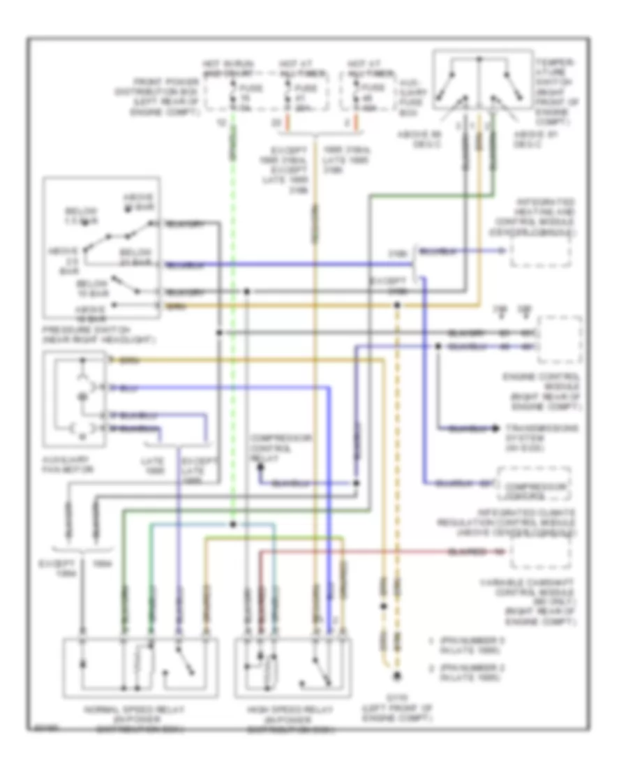
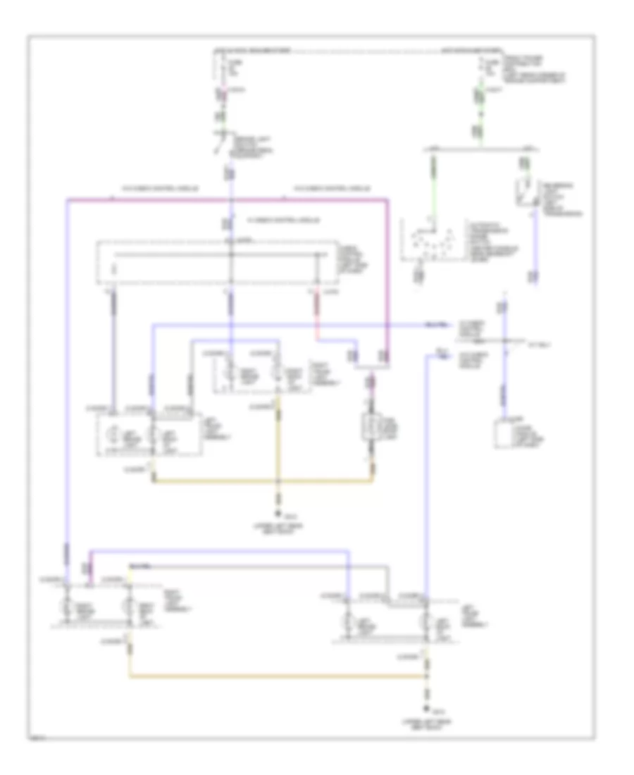
COOLING FAN Cooling Fan Wiring Diagram for BMW 325i 1994 https://portal-diagnostov.com/license.html
https://portal-diagnostov.com/license.html
Automotive Electricians Portal FZCO
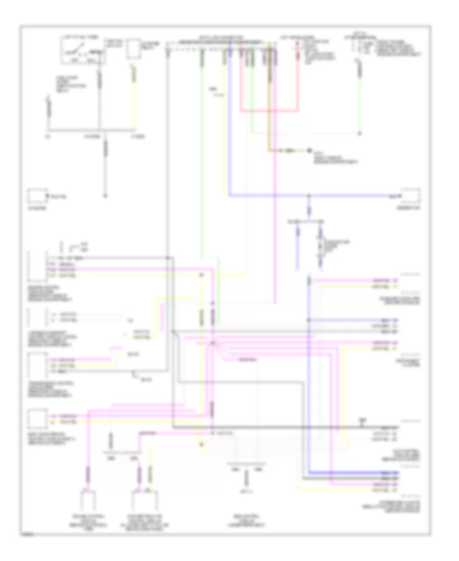
Automotive Electricians Portal FZCO すべての配線図にアクセスする車 List of elements for Cooling Fan Wiring Diagram for BMW 325i 1994: (in power (pin number 2 (pin number 5 1995 318i/s, late 1995 318ti 318ti Above 18 bar Above 2.6 bar Above 30 bar Above 91 deg c Above 99 deg c Aux- iliary fuse box Auxiliary fan motor Below 1.5 bar Below 15 bar Below 21 bar Compressor control Compressor control relay Distribution box) Engine control module (right rear of engine compt) Except Except 1995 318i/s, except late 1995 318ti Except 318ti Except late Fuse 30a Fuse 40a Fuse 5a G110 (left front of engine compt) High speed relay Hot at all times Hot in run and start front power distribution box (left rear of engine compt) In late 1995) Integrated climate regulation control module (above center console) Integrated heating and control module (center console) Late Normal speed relay Pressure switch (near right headlight) Temper- ature switch (right front of engine compt) Transmissions system (w/ egs) Variable camshaft control module (m3 only) (right rear of engine compt)
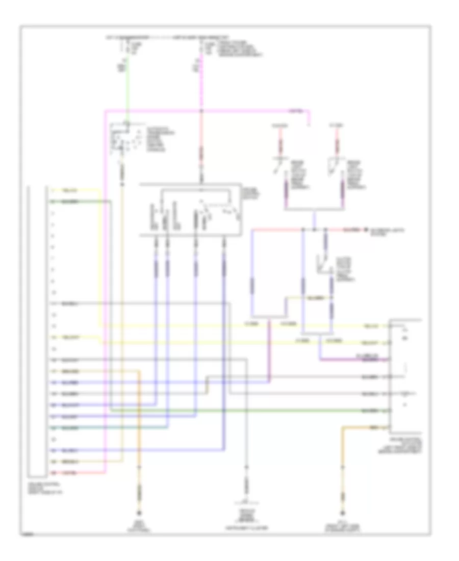
CRUISE CONTROL Cruise Control Wiring Diagram for BMW 325i 1994 https://portal-diagnostov.com/license.html
https://portal-diagnostov.com/license.html
Automotive Electricians Portal FZCO
Automotive Electricians Portal FZCO すべての配線図にアクセスする車 List of elements for Cruise Control Wiring Diagram for BMW 325i 1994: Acccelerate/ set Automatic transmission range switch (center console) Brake light switch (top of brake pedal support) Clutch switch (top of clutch pedal support) Cruise control actuator (left front side of engine compartment) Cruise control module (right side of i/p) Cruise control switch Decelerate/ set Exterior lights system Front power distribution box (rear left side of engine compartment) Fuse f28 5a Fuse f46 15a G111 (front left side of engine compt)) G203 (right kick panel) Hot in accy, run and start Hot in run and start Instrument cluster Nca Normal Off Resume Vehicle speed sensor W/ ccm W/ egs W/o ccm W/o egs
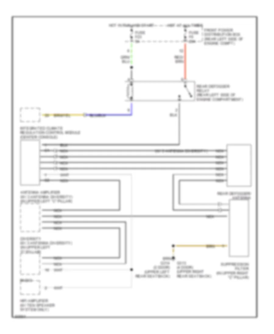
DEFOGGERS Defogger Wiring Diagram for BMW 325i 1994 https://portal-diagnostov.com/license.html
https://portal-diagnostov.com/license.html
Automotive Electricians Portal FZCO
Automotive Electricians Portal FZCO すべての配線図にアクセスする車 List of elements for Defogger Wiring Diagram for BMW 325i 1994: (w/ 3 antenna diversity) Antenna amplifier (w/ 3 antenna diversity) (in upper left "c" pillar) Diversity (w/ 3 antenna diversity) (in upper left "c" pillar) Front power distribution box (rear left side of engine compt) Fuse f23 5a Fuse f6 20a G313 (4 door) (upper right rear seatback) G314 (2 door) (upper left rear seatback) Hifi amplifier (w/ ten speaker system only) Hot at all times Hot in run and start Integrated climate regulation control module (center console) Nca Radio Rear defogger relay (rear left side of engine compartment) Rear defogger/ antenna Suppression filter (in upper right "c" pillar)
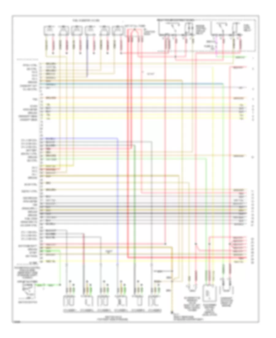
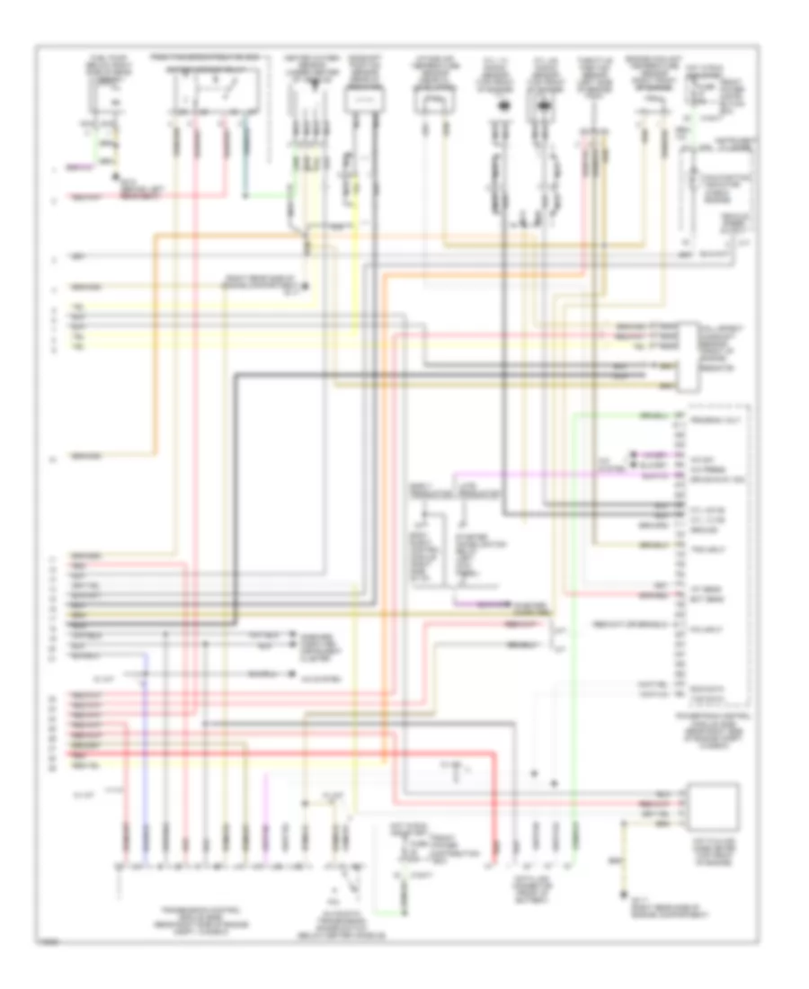
ENGINE PERFORMANCE 2.5L 2.5L, Engine Performance Wiring Diagrams (1 of 2) for BMW 325i 1994 https://portal-diagnostov.com/license.html
https://portal-diagnostov.com/license.html
Automotive Electricians Portal FZCO
Automotive Electricians Portal FZCO すべての配線図にアクセスする車 List of elements for 2.5L, Engine Performance Wiring Diagrams (1 of 2) for BMW 325i 1994: (top right side of engine) 15a 5v ref 87a A/c comp ctrl Acc B+ junction point Battery Camshaft act Camshaft actuator (front of engine) Camshft sens Crank rpm (-) Crank rpm td Crnkshft sens Cyl 1 ign coil Cyl 2 ign coil Cyl 3 ign coil Cyl 4 ign coil Cyl 5 ign coil Cyl 6 ign coil Cylinder 1 Cylinder 2 Cylinder 3 Cylinder 4 Cylinder 5 Cylinder 6 Ecm rly ctrl Engine control module relay Evap ctrl Evaporative emission valve (right of left front shock tower) Fp rly ctrl Front power distribution box Fuel cons Fuel injector valves Fuel pump relay Fuse 18 G117 (right rear side of engine compartment) Ground Hfam meter Hot at all times Idle speed control valve (near oil level stick) Ign timing Ignition coils Ignition switch Inj 1 Inj 2 Inj 3 Inj 4 Inj 5 Inj 6 Isc ctrl Mil ind ctrl Nca O2 sig O2s ground O2s rly ctrl Off Powertrain control module (dme) (rear right side of engine compt, in e-box) Red Run Start Switched batt Tps Vss W/ a/t
2.5L, Engine Performance Wiring Diagrams (2 of 2) for BMW 325i 1994 https://portal-diagnostov.com/license.html
https://portal-diagnostov.com/license.html
Automotive Electricians Portal FZCO
Automotive Electricians Portal FZCO すべての配線図にアクセスする車 List of elements for 2.5L, Engine Performance Wiring Diagrams (2 of 2) for BMW 325i 1994: (right rear side of A/c press A/c sw A/c system A/t Automatic transmission range switch (below center console) Body elect. control module (right side of i/p) Camshaft position sensor (rear of radiator) Cyl 1-3 knock sensor (top front of engine) Cyl 1-3 ks Cyl 4-6 knock sensor (top front of engine) Cyl 4-6 ks Data link connector (front of battery) Drive-away sig Early production Ect sens Engine compartment) Engine coolant temperature sensor (right front of engine) Front power distri- bution box x10017 Front power distribution box Fuel pump (below right side of rear seat) Fuse 5a G117 G117 (right rear side of engine compartment) G312 (behind left rear seat) Ground Hall effect camshaft sensor (front of engine) Heated oxygen sensor (under center of vehicle) Hot film air mass meter (top front of engine) Hot in run and start Iat sens Instrument cluster Intake air temperature sensor (near oil level stick) Late production M/t Malfunction indicator (check engine) Nca On-board computer On-board computer, instrument cluster Oxygen sensor relay P/n P/n input Powertrain control module (dme) (rear right side of engine compt, in e-box) Program volt Red Resistor Rxd data Starter immobilization relay (left kick panel) Throttle position sensor (left side of engine) Tps input Transmission control module (egs) (rear right side of engine compt, in e-box) Txd data Vehicle speed output W/ a/t X10017 X16 X17 X511
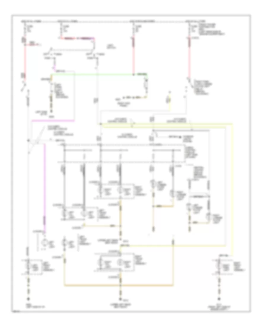
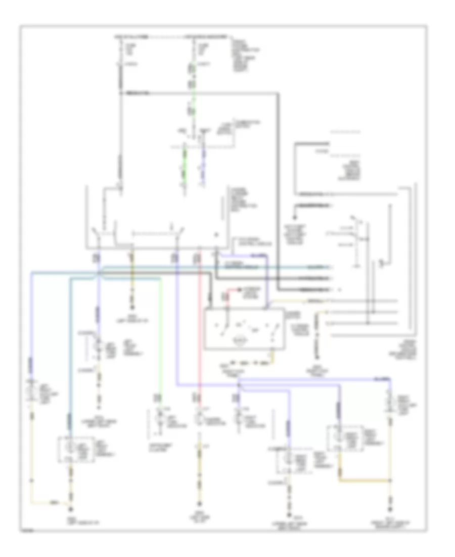
EXTERIOR LIGHTS Exterior Light Wiring Diagram, Canada (1 of 3) for BMW 325i 1994 https://portal-diagnostov.com/license.html
https://portal-diagnostov.com/license.html
Automotive Electricians Portal FZCO
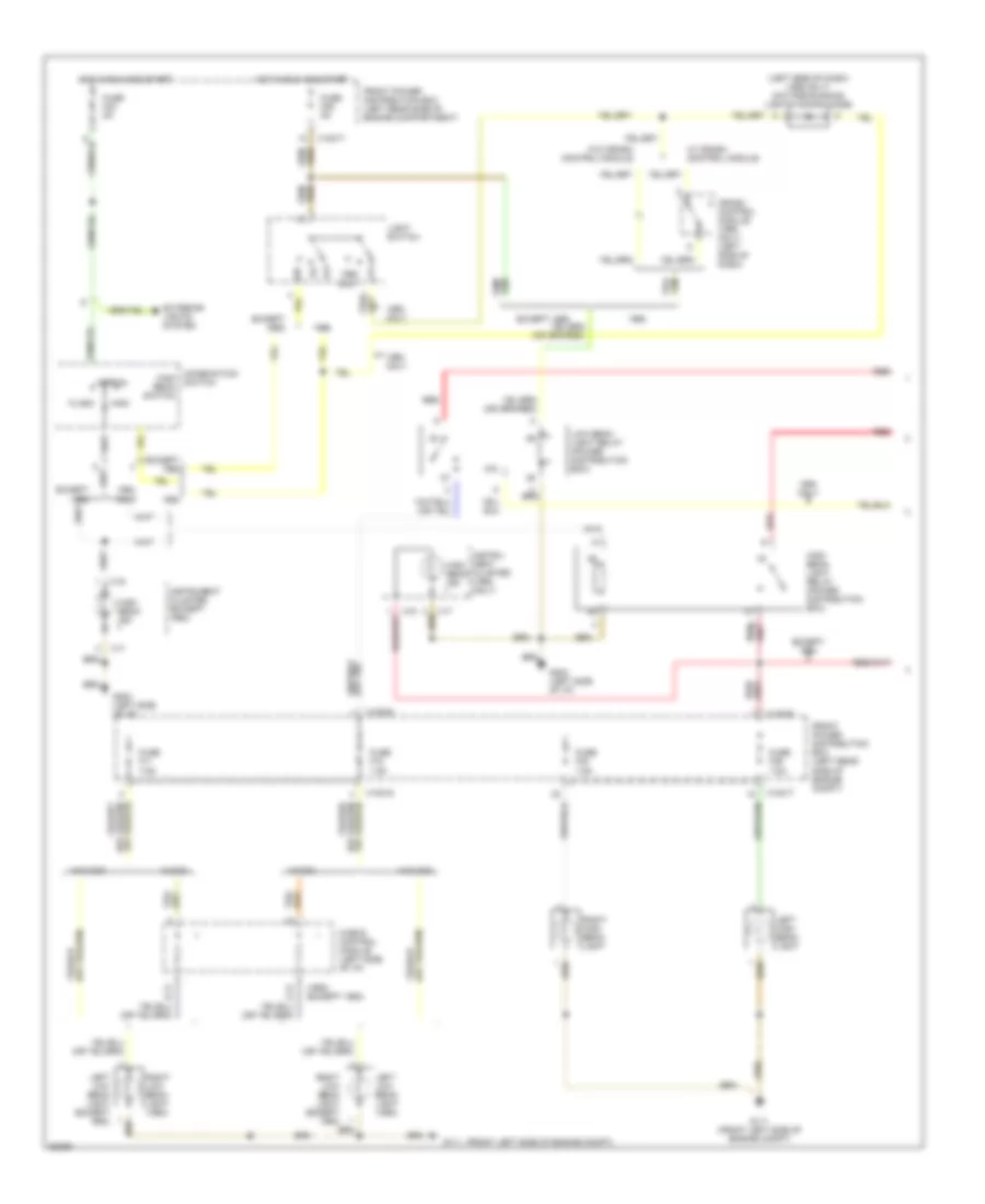
Automotive Electricians Portal FZCO すべての配線図にアクセスする車 List of elements for Exterior Light Wiring Diagram, Canada (1 of 3) for BMW 325i 1994: (2 door) (not used) (right kick panel) (upper left rear seat back) Anti-theft system (anti-theft control module) Central locking module (behind glove box) Combination switch Crash control module (driver's side footwell) Front power distribution box (left rear side of engine compt.) Fuse f23 5a Fuse f34 15a G111 (front left side of engine compt.) G202 (left side of i/p) G203 G203 (right kick panel) G312 G312 (upper left rear seat back) Hazard flasher relay (power distribution box) Hazard indicator Hazard switch Hot at all times Hot in run and start Instrument cluster Interior lights system Left Left front auxiliary turn light Left front light assembly Left front turn lamp Left rear turn lamp Left trunk light assembly Left turn indicator Nca Off Right Right front auxiliary turn light Right front light assembly Right front turn lamp Right rear turn lamp Right trunk light assembly Right turn indicator Turn signal switch W/ crash control module W/o crash control module X10017 X10018 X13012 X16 X17
Exterior Light Wiring Diagram, Canada (2 of 3) for BMW 325i 1994 https://portal-diagnostov.com/license.html
https://portal-diagnostov.com/license.html
Automotive Electricians Portal FZCO
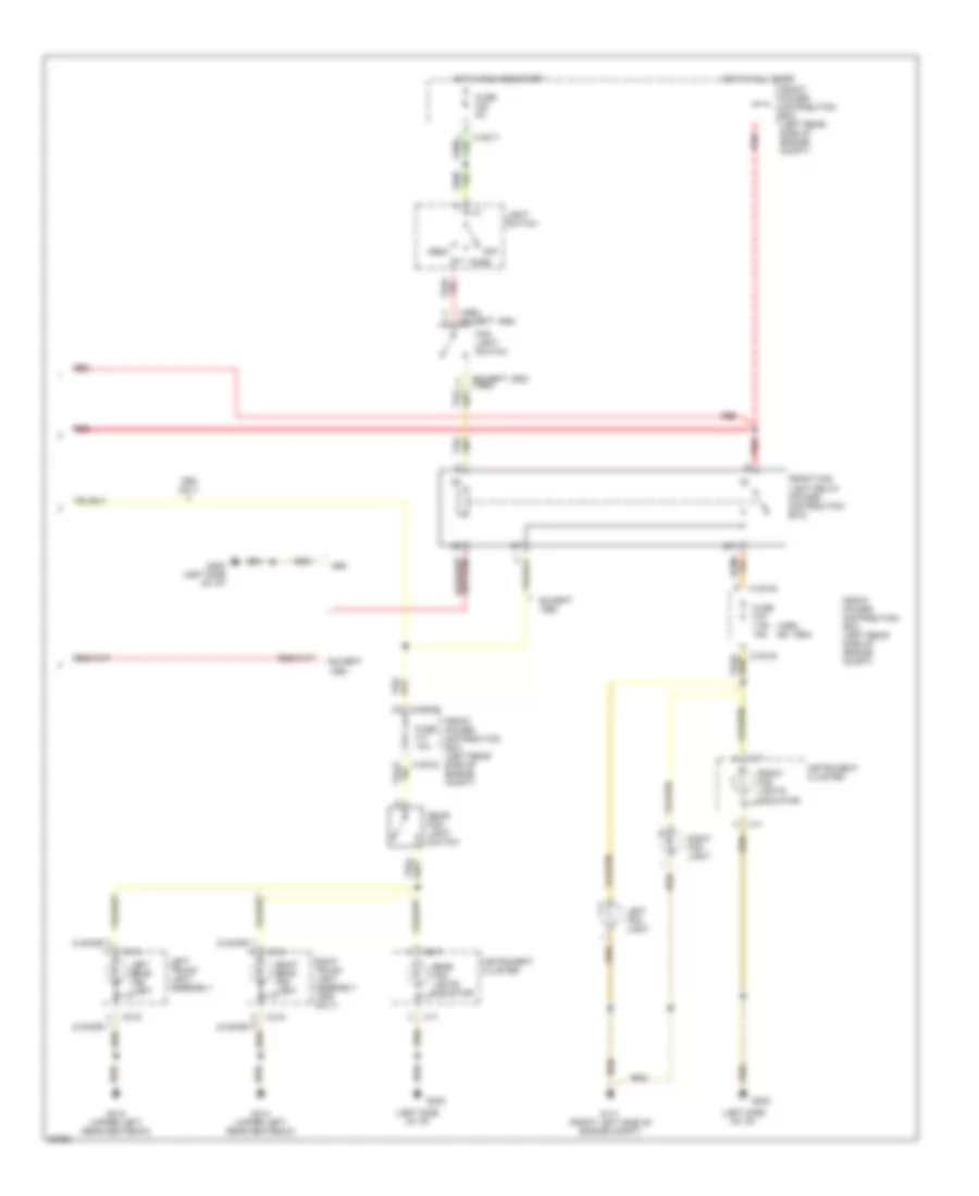
Automotive Electricians Portal FZCO すべての配線図にアクセスする車 List of elements for Exterior Light Wiring Diagram, Canada (2 of 3) for BMW 325i 1994: (2 door) (left side of i/p) (right kick panel) (upper left rear seat back) Central locking module (behind glove box) Check control module (left side of dash) Front power distribution box (left rear side of engine compartment) Fuse 10a Fuse 5a G111 (front left side of engine compt.) G202 G202 (left side of i/p) G203 G312 Head Hot at all times Hot in run and start Interior lights system Left front light assembly Left license plate light Left park light Left park light relay (behind glove box) Left tail light Left trunk light assembly Light switch Off Park Right front light assembly Right license plate light Right park light Right park light/license plate light relay (behind glove box) Right tail light Right trunk light assembly W/ check control module W/o check control module X10018 X1074 X1075 X13014
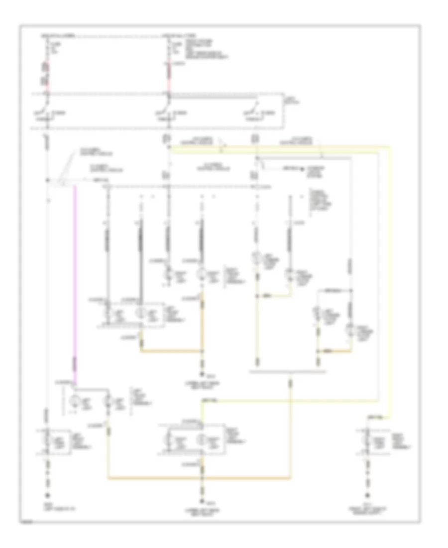
Exterior Light Wiring Diagram, Canada (3 of 3) for BMW 325i 1994 https://portal-diagnostov.com/license.html
https://portal-diagnostov.com/license.html
Automotive Electricians Portal FZCO
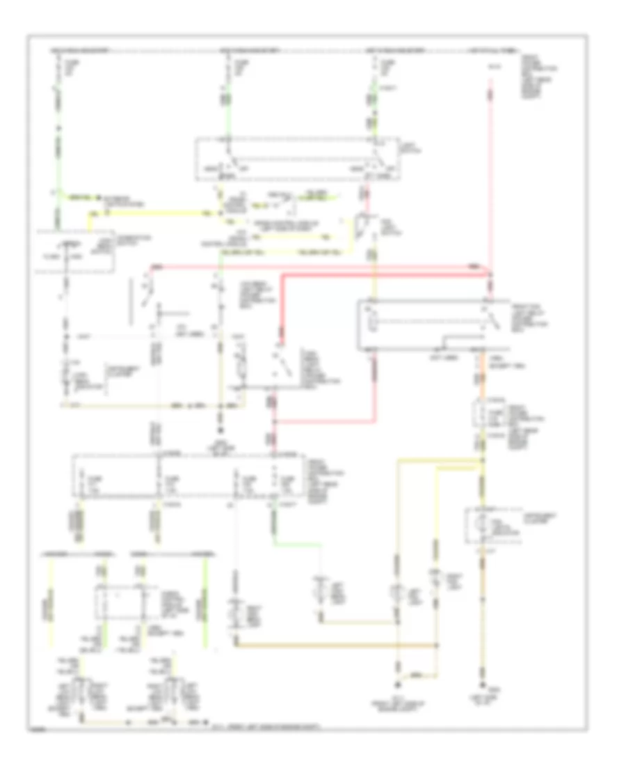
Automotive Electricians Portal FZCO すべての配線図にアクセスする車 List of elements for Exterior Light Wiring Diagram, Canada (3 of 3) for BMW 325i 1994: (2 door) (upper left rear seat back) A/t A/t only Automatic transmission range switch (center console near gearshift lever) Brake light switch (brake pedal support) Check control module (left side of dash) Chime module (left side of dash) Front power distribution box (left rear corner of engine compartment) Fuse 10a Fuse 15a G312 High level stop light Hot in accy, run and start Hot in run and start Left back up light Left brake light Left trunk light assembly M/t Nca Reversing light switch (left side of transmission) Right back up light Right brake light Right trunk light assembly W/ check control module W/o check control module X10018 X1074 X1075 X1426
Exterior Light Wiring Diagram, USA (1 of 3) for BMW 325i 1994 https://portal-diagnostov.com/license.html
https://portal-diagnostov.com/license.html
Automotive Electricians Portal FZCO
Automotive Electricians Portal FZCO すべての配線図にアクセスする車 List of elements for Exterior Light Wiring Diagram, USA (1 of 3) for BMW 325i 1994: (2 door) (right kick panel) (upper left rear seat back) Anti-theft system (anti-theft control module) Body control module (behind glove box) Combination switch Crash control module (driver's side footwell) Front power distribution box (left rear side of engine compt.) Fuse f23 5a Fuse f34 15a G111 (front left side of engine compt.) G202 (left side of i/p) G203 G203 (right kick panel) G312 G312 (upper left rear seat back) Hazard flasher relay (power distribution box) Hazard indicator Hazard switch Hot at all times Hot in run and start Instrument cluster Interior lights system Left Left front auxiliary turn light Left front light assembly Left front turn lamp Left rear turn lamp Left trunk light assembly Left turn indicator Nca Off Right Right front auxiliary turn light Right front light assembly Right front turn lamp Right rear turn lamp Right trunk light assembly Right turn indicator Turn signal switch W/ crash control module W/o crash control module X10017 X10018 X10182 X16 X17
Exterior Light Wiring Diagram, USA (2 of 3) for BMW 325i 1994 https://portal-diagnostov.com/license.html
https://portal-diagnostov.com/license.html
Automotive Electricians Portal FZCO
Automotive Electricians Portal FZCO すべての配線図にアクセスする車 List of elements for Exterior Light Wiring Diagram, USA (2 of 3) for BMW 325i 1994: (2 door) (upper left rear seat back) Check control module (left side of dash) Front power distribution box (left rear side of engine compartment) Fuse 10a G111 (front left side of engine compt.) G202 (left side of i/p) G312 Head Hot at all times Interior lights system Left front light assembly Left license plate light Left park light Left tail light Left trunk light assembly Light switch Off Park Right front light assembly Right license plate light Right park light Right tail light Right trunk light assembly W/ check control module W/o check control module X10018 X1074 X1075
Exterior Light Wiring Diagram, USA (3 of 3) for BMW 325i 1994 https://portal-diagnostov.com/license.html
https://portal-diagnostov.com/license.html
Automotive Electricians Portal FZCO
Automotive Electricians Portal FZCO すべての配線図にアクセスする車 List of elements for Exterior Light Wiring Diagram, USA (3 of 3) for BMW 325i 1994: (2 door) (upper left rear seat back) A/t A/t only Automatic transmission range switch (center console near gearshift lever) Brake light switch (brake pedal support) Check control module (left side of dash) Chime module (left side of dash) Front power distribution box (left rear corner of engine compartment) Fuse 10a Fuse 15a G312 High level stop light Hot in accy, run and start Hot in run and start Left back up light Left brake light Left trunk light assembly M/t Nca Reversing light switch (left side of transmission) Right back up light Right brake light Right trunk light assembly W/ check control module W/o check control module X10018 X1074 X1075 X1426
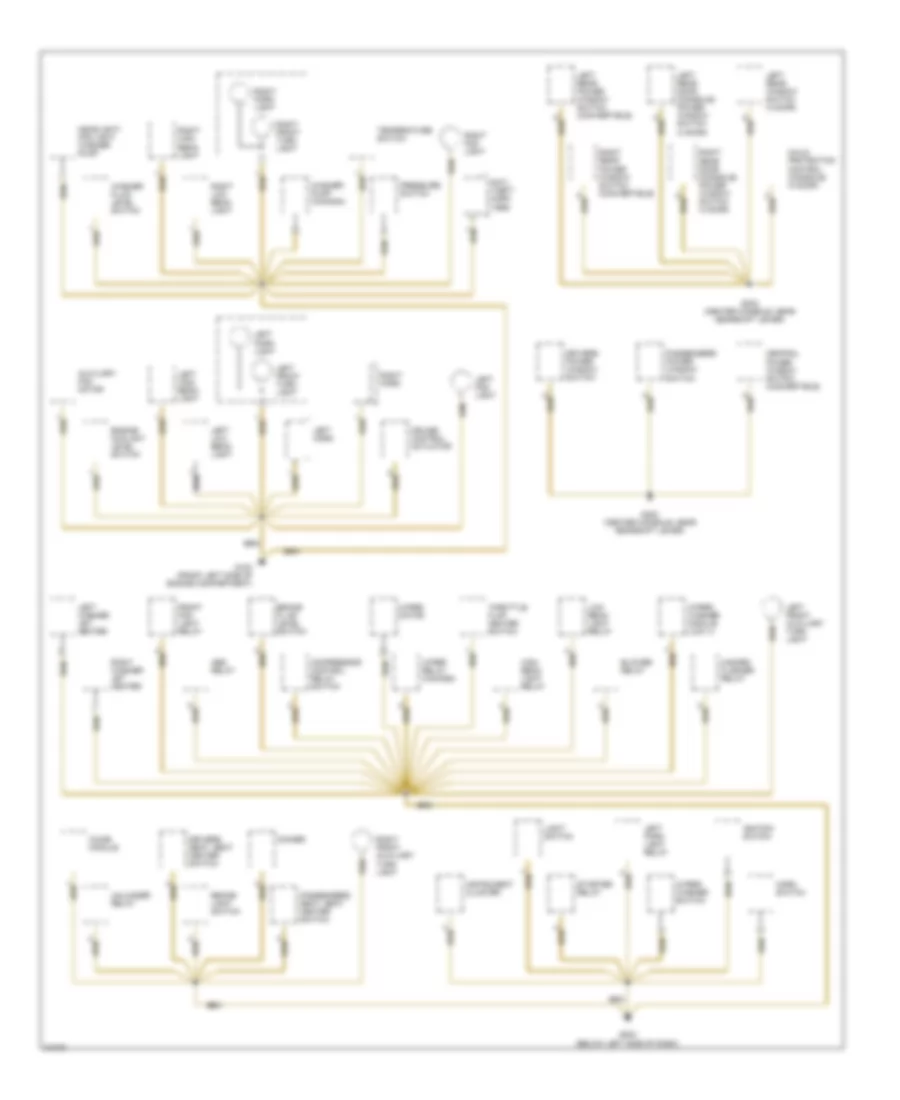
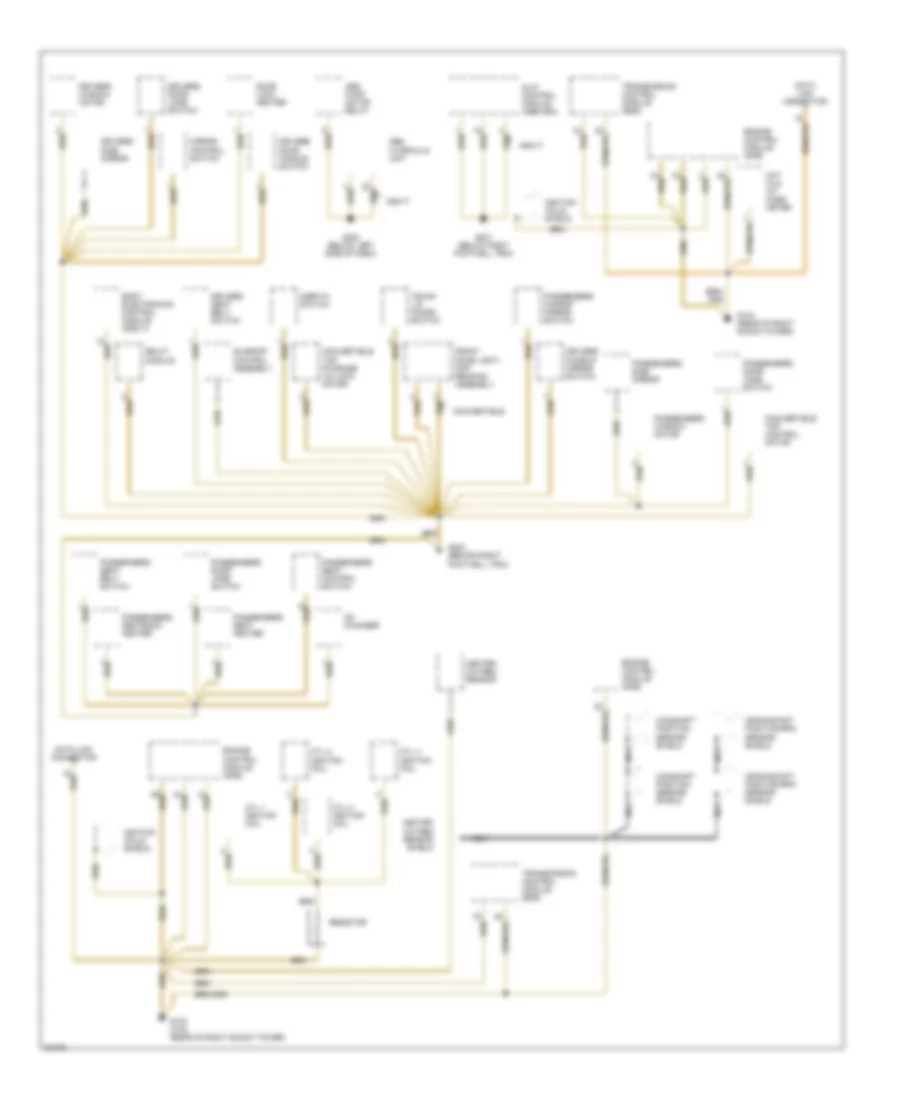
GROUND DISTRIBUTION Ground Distribution Wiring Diagram (1 of 5) for BMW 325i 1994 https://portal-diagnostov.com/license.html
https://portal-diagnostov.com/license.html
Automotive Electricians Portal FZCO
Automotive Electricians Portal FZCO すべての配線図にアクセスする車 List of elements for Ground Distribution Wiring Diagram (1 of 5) for BMW 325i 1994: Abs relay Anti- theft horn (1995) Auxiliary fan motor Blower relay Brake fluid level switch Brake light switch Central power window switch (convertible) Child protection control (console) (4 door) Chime module Compressor control relay switch Cruise control actuator Dimmer Drivers power window switch Drivers seat, seat heater switch Engine coolant level switch Front fog light relay G100 (front left side of engine compartment) G202 (below left side of dash) G302 (center console, near gearshift lever) Hazard flasher relay Headlight/ fog light washer pump High beam light relay Horn switch Ignition switch Instrument cluster Left fog light Left front auxiliary turn light Left front turn light Left high beam light Left horn Left low beam light Left park light Left park light relay Left rear door (console) power window switch (4 door) Left rear power window switch (convertible) Left rear window switch (4 door) Left washer jet heater Light switch Low beam light relay Passengers power window switch Passengers seat, seat heater switch Pressure switch Right fog light Right front auxiliary turn light Right front turn light Right high beam light Right horn Right low beam light Right park light Right rear door (console) power window switch (4 door) Right rear power window switch (convertible) Right washer jet heater Starter relay Temperature switch Throttle flap heater switch Unloader relay Washer fluid level switch Washer pump (canada) Wiper motor Wiper relay (canada) Wiper/ washer module (low ii) Wiper/ washer switch
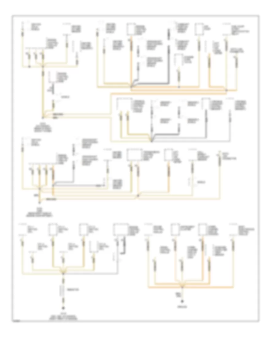
Ground Distribution Wiring Diagram (2 of 5) for BMW 325i 1994 https://portal-diagnostov.com/license.html
https://portal-diagnostov.com/license.html
Automotive Electricians Portal FZCO
Automotive Electricians Portal FZCO すべての配線図にアクセスする車 List of elements for Ground Distribution Wiring Diagram (2 of 5) for BMW 325i 1994: Abs hydraulic unit Abs pump motor relay Asc+t Body electronics control module (zke iv) Camshaft position sensor shield Cd changer Convertible Convertible top control motor Convertible top storage lid lock motor Crankshaft position/rpm sensor shield Cyl 1 ignition coil Cyl 2 ignition coil Cyl 3 ignition coil Cyl 4 ignition coil Data link connector Door lock heater Drivers door handle switch Drivers door jamb switch Drivers makeup mirror switch Drivers seat belt switch Drivers side mirror Drivers window motor Engine control module (dme) Front dome light/ map reading assembly G103 (318i) (rear of right shock tower) G103 (rear of right shock tower) G201 (below right footwell trim) G202 (below left side of dash) G203 (behind right footwell trim) Heated oxygen sensor Heated oxygen sensor shield Hot film ait mass meter Ignition coils shield Inertia switch Mirror control switch Nca Passengers door jamb switch Passengers makeup mirror switch Passengers seat belt switch Passengers seat control switch Passengers seat heater Passengers seatback heater Passengers side mirror Passengers window motor Relay module Resistor Slip control module (abs/asc) Sunroof control assembly Transmission control module (egs) Trunk lid macro switch
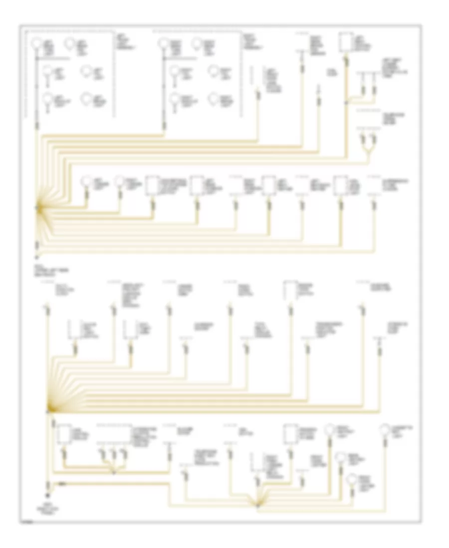
Ground Distribution Wiring Diagram (3 of 5) for BMW 325i 1994 https://portal-diagnostov.com/license.html
https://portal-diagnostov.com/license.html
Automotive Electricians Portal FZCO
Automotive Electricians Portal FZCO すべての配線図にアクセスする車 List of elements for Ground Distribution Wiring Diagram (3 of 5) for BMW 325i 1994: Air pump Body electronics control module Camshaft position sensor shield Change- over valve Crankshaft position/rpm sensor shield Crash control module Cruise control module Cyl 1 ignition coil Cyl 2 ignition coil Cyl 3 ignition coil Cyl 4 ignition coil Cyl 5 ignition coil Cyl 6 ignition coil Data link connector Engine control module (dme) Fuel pump/ start identification relay G103 (m3 canada) (rear of right shock tower) G119 (320i, 325i, m3 canada) (right front of engine) G123 (325i) (rear right side of engine compartment) Ground Hall effect camshaft sensor Heated oxygen sensor Heated oxygen sensor 2 Heated oxygen sensor 2 shield Heated oxygen sensor shield Hot film air mass meter Ignition coils shield Instrument cluster Nca On-board computer temp sensor Resistor Sensor 1 shield Sensor 2 shield Shield Transmission control module (egs) Variable camshaft control module (vanos) Variable camshaft control sensor 1 Variable camshaft control sensor 2 Wiper/ washer module (canada) Wiper/ washer module (low ii) (usa)
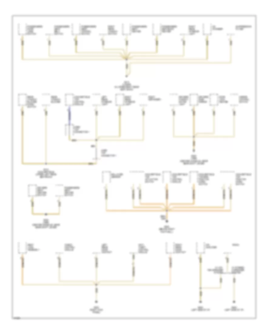
Ground Distribution Wiring Diagram (4 of 5) for BMW 325i 1994 https://portal-diagnostov.com/license.html
https://portal-diagnostov.com/license.html
Automotive Electricians Portal FZCO
Automotive Electricians Portal FZCO すべての配線図にアクセスする車 List of elements for Ground Distribution Wiring Diagram (4 of 5) for BMW 325i 1994: Anti- theft horn Asc switch Blower motor Cassette box light Charging socket Convertible top storage lid micro switch Engine hood switch Front ashtray light Front cigar lighter Front cigar lighter light Fuel pump G203 (right kick panel) G312 (upper left rear seatback) Glove box light switch Hazard switch horn Headlight/ foglight cleaning module (sra) (canada) High level stop light Ihkr control module Integrated climate regulation control module Intensive wash pump Left back-up light Left brake light Left front door jamb switch (4 door) Left license light Left rear fog light Left rear interior light Left rear turn light Left seat control switch Left seat heater Left seat lumbar support motor/valve (1995) Left seatback heater Left tail light Left trunk light assembly Multi- function clock On-board computer Program switch (w/ egs) Radio micro- switch Rear ashtray light Right back-up light Right brake light Right license light Right park/ license light relay (canada) Right rear brake pad sensor Right rear fog light Right rear interior light Right rear turn light Right tail light Right trunk light assembly Suppression filter (2 door) Telephone eject box (late production) Telephone trans- ceiver Transmission position indicator light Twin relay module (canada)
Ground Distribution Wiring Diagram (5 of 5) for BMW 325i 1994 https://portal-diagnostov.com/license.html
https://portal-diagnostov.com/license.html
Automotive Electricians Portal FZCO
Automotive Electricians Portal FZCO すべての配線図にアクセスする車 List of elements for Ground Distribution Wiring Diagram (5 of 5) for BMW 325i 1994: Anti- theft control module Cd changer Check control module Convertible top actuating switch Convertible top control module Convertible top position micro switch Convertible top-end position micro switch Door lock heater Drivers seat heater switch Drivers side mirror Drivers window motor light G202 (left side of i/p) G203 (behind right footwell) G203 (right kick panel) G302 (1995) (center console, near gear shift lever) G312 (convertible) (upper left rear seatback) G313 (4 door) (in upper right rear seat back) Hard top connector 1 Hifi amplifier Left rear door contact Left rear interior light Mirror control switch Passengers door jamb switch Passengers seat belt switch Passengers seat control switch Passengers seat heater Passengers seat heater switch Passengers seatback heater Radio Rear window blower Rear window blower micro switch Right defogger i Right rear door contact Right rear interior light Right rear window switch Rollover sensor Seat load assembly Suppression filter W/ hifi, ten speaker system W/ stereo 6 speaker system
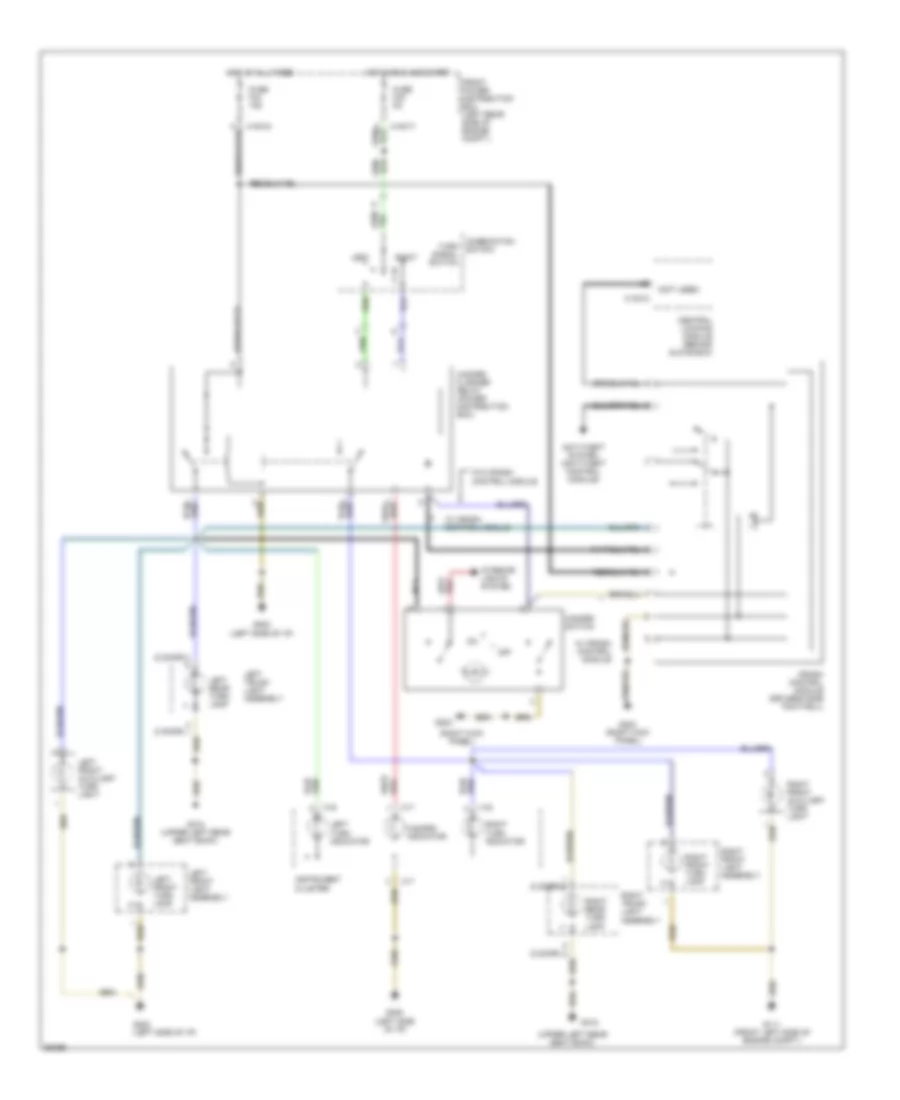
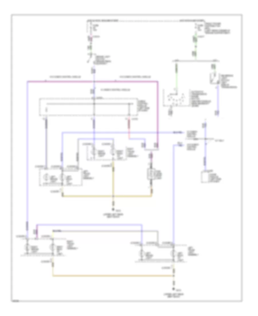
HEADLIGHTS Headlight Wiring Diagram, with DRL (1 of 2) for BMW 325i 1994 https://portal-diagnostov.com/license.html
https://portal-diagnostov.com/license.html
Automotive Electricians Portal FZCO
Automotive Electricians Portal FZCO すべての配線図にアクセスする車 List of elements for Headlight Wiring Diagram, with DRL (1 of 2) for BMW 325i 1994: (1993) (except 1993) (front left side of engine compt) (left side of dash) (1992 0nly) daytime running lights coding diode 0nly 87b Check control module (left side of i/p) Combination high beam switch Crash control module (1992 only) (left side of dash) Except Except 1992 Exterior lights system Flash Front power distribution box (left rear side of engine compartment) Front power distribution box (left rear side of engine compt) Fuse f11 7.5a Fuse f12 7.5a Fuse f23 5a Fuse f25 5a Fuse f29 7.5a Fuse f30 7.5a G111 G111 (front left side of engine compt) G202 (left side of i/p) High High beam ind High beam light relay (power distribution box) Hot in run and start Instru- ment cluster (1994 only) Instrument cluster (except 1994) Left high beam light Left low beam light (1993) Left low beam light (except 1993) Light switch Low beam light relay (power distribution box) Normal Off Only Red Right high beam light Right low beam light (1993) Right low beam light (except 1993) Switch W/ crash control module W/ccm W/o ccm W/o crash control module X10016 X10017 X10035 X10036 X16 X17
Headlight Wiring Diagram, with DRL (2 of 2) for BMW 325i 1994 https://portal-diagnostov.com/license.html
https://portal-diagnostov.com/license.html
Automotive Electricians Portal FZCO
Automotive Electricians Portal FZCO すべての配線図にアクセスする車 List of elements for Headlight Wiring Diagram, with DRL (2 of 2) for BMW 325i 1994: (1994) (ex 1994) (1994) (except 1994) (2 door) (except 1994) (1994) (left side of i/p) 87b Except Fog light switch Front fog light relay (power distribution box) Front fog lights indicator Front power distribution box (left rear side of engine compt) Fuse f15 7.5a 15a Fuse f17 10a Fuse f22 5a G111 (front left side of engine compt) G202 G202 (left side of i/p) G312 (upper left rear seatback) Head Hot at all times Hot in run and start Instrument cluster Left fog light Left rear fog light Left trunk light assembly Light switch Off Only Park Rear fog light switch Rear fog lights indicator Red Right fog light Right rear fog light Right trunk light assembly (1993 only) X10016 X10017 X17 X217 X318 X319
Headlight Wiring Diagram, without DRL for BMW 325i 1994 https://portal-diagnostov.com/license.html
https://portal-diagnostov.com/license.html
Automotive Electricians Portal FZCO
Automotive Electricians Portal FZCO すべての配線図にアクセスする車 List of elements for Headlight Wiring Diagram, without DRL for BMW 325i 1994: (1993) (except 1993) (1994) (except 1994) (front left side of engine compt) (left side of i/p) (not used) 1992 0nly 87b Check control module (left side of i/p) Combination high beam switch Crash control module (left side of dash) Exterior lights system Flash Fog light switch Fog lights indicator Front fog light relay (power distribution box) Front power distribution box (left rear side of engine compt) Fuse f11 7.5a Fuse f12 7.5a Fuse f15 7.5a Fuse f22 5a Fuse f23 5a Fuse f25 5a Fuse f29 7.5a Fuse f30 7.5a G111 G111 (front left side of engine compt) G202 G202 (left side of i/p) Head High High beam indicator High beam light relay (power distribution box) Hot at all times Hot in run and start Instrument cluster Left fog light Left high beam light Left low beam light (1993) Left low beam light (except 1993) Light switch Low beam light relay (power distribution box) Normal Off Park Red Right fog light Right high beam light Right low beam light (1993) Right low beam light (except 1993) Switch W/ crash control module W/ccm W/o ccm W/o crash control module X10016 X10017 X10035 X10036 X16 X17
HORN Horn Wiring Diagram for BMW 325i 1994 https://portal-diagnostov.com/license.html
https://portal-diagnostov.com/license.html
Automotive Electricians Portal FZCO
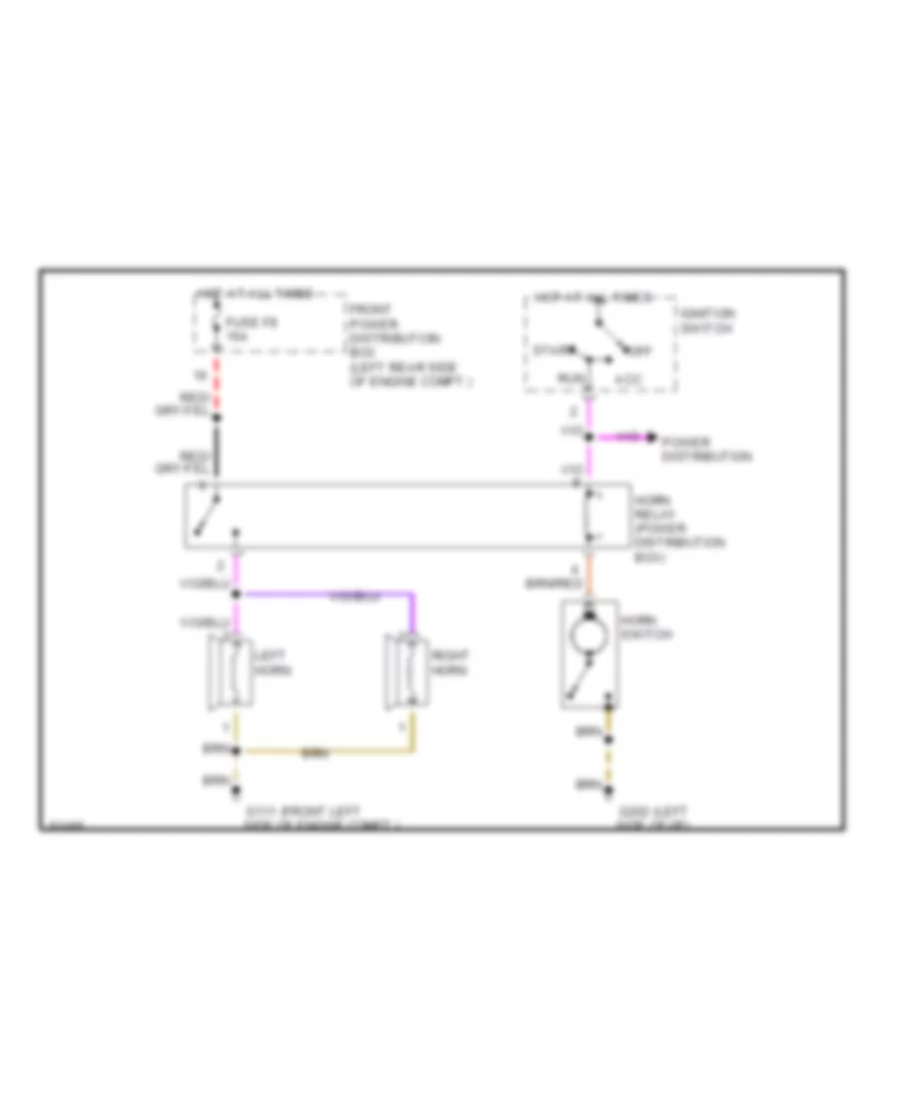
Automotive Electricians Portal FZCO すべての配線図にアクセスする車 List of elements for Horn Wiring Diagram for BMW 325i 1994: (front left (left Acc Front power distribution box (left rear side of engine compt.) Fuse f8 15a G111 side of engine compt.) G202 side of i/p) Horn relay (power distribution box) Horn switch Hot at all times Ignition switch Left horn Off Power distribution Right horn Run Start
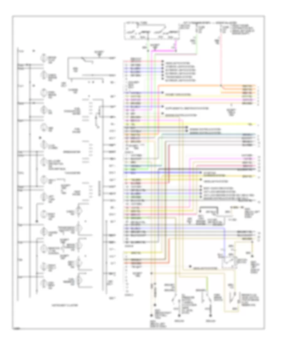
INSTRUMENT CLUSTER Instrument Cluster Wiring Diagram (1 of 2) for BMW 325i 1994 https://portal-diagnostov.com/license.html
https://portal-diagnostov.com/license.html
Automotive Electricians Portal FZCO
Automotive Electricians Portal FZCO すべての配線図にアクセスする車 List of elements for Instrument Cluster Wiring Diagram (1 of 2) for BMW 325i 1994: (near oil level stick) 0nly A10 A11 A12 A13 A14 A15 A16 A17 A18 A19 A20 A21 A22 A23 Abs ind Acc Anti- lock brakes system Anti-lock brakes system Anti-lock brakes system (ex 1992 & 1993) Asc+t ind B11 B12 B14 B15 B16 B17 B18 B19 B21 B23 B24 B26 Body computer system Brake fluid ind Brake fluid level switch (top of brake fluid reservoir) Brake warning ind Charge Check engine ind Check ind Conn a Conn b Conn c Convert- Engine controls system Engine controls system (1997 only) Except Except & Except 1992 & Exterior lights system Front fog lt ind Front power distribution box (rear left side of engine compt) Fuel consumption meter Fuel gauge Fuel reserve ind Fuse f27 5a Fuse f31 5a G202 (below left side of dash) G203 (behind right footwell trim) Ground Hazard ind Headlights system High beam ind Hot at all times Hot in run and start Ible only Ignition switch Illum (3 used) Ind Instrument cluster Interior lights system Left turn ind Lock Nca Oil ind Oil pressure switch 1) normal 2) 0.2-0.5 bar Only Park brake ind Park brake switch Power tops system Rear fog lt ind (canada) Right turn ind Rollover protection ind (convertible) Run Seat belt ind Solid state Speedometer Srs ind Start Starting/ charging system Tachometer Temp gauge Transmission malfunction ind Transmission system W/ asc W/o asc
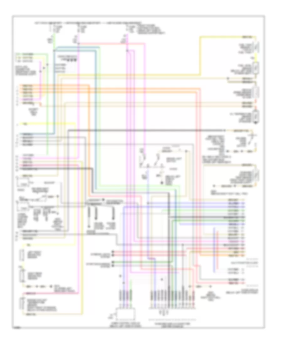
Instrument Cluster Wiring Diagram (2 of 2) for BMW 325i 1994 https://portal-diagnostov.com/license.html
https://portal-diagnostov.com/license.html
Automotive Electricians Portal FZCO
Automotive Electricians Portal FZCO すべての配線図にアクセスする車 List of elements for Instrument Cluster Wiring Diagram (2 of 2) for BMW 325i 1994: (1992 & 1993 usa, & 1997) (behind right footwell trim) (1992 & 1993 2 door, & convertible) g203 (below left side of dash) (g202) (ex 1992 & 1993 2 door, & 1994 convertible) (upper left rear seat) (ex 1992 & 1993 usa, & 1997) Air condition- ing system Brake light switch Check control module (below left side of dash) Chime module (below left side of dash) Clc Computer data lines system Cruise control system Data Data link connector (rear right side of engine compt) Driver's seat belt switch Drivers door jamb switch Engine controls system Engine coolant temperature sensor (right front of engine, below intake manifold) Except 1992 & Front power distribution box (rear left side of engine compartment) Fuel level sensor (below left side of rear seat) Fuel tank sensor ii (top of fuel tank) Fuse f23 5a Fuse f45 7.5a Fuse f46 15a G203 (behind right foot well trim) G203 (behind right footwell trim) G312 G312 (in upper left rear seat back) Hot in accy, run and start Hot in run and start Interior lights system Lac Left front brake pad sensor Multi-function clock Oil temperature sensor (left side of engine) On-board computer temp sensor (front right side of engine compt) On-board display/computer (center console) Power tops system Radio Right rear brake pad sensor Starting/charging system Tach Vehicle speed sensor (under rear of car) W/ ccm W/ccm Wiper/ washer module (behind glove box)
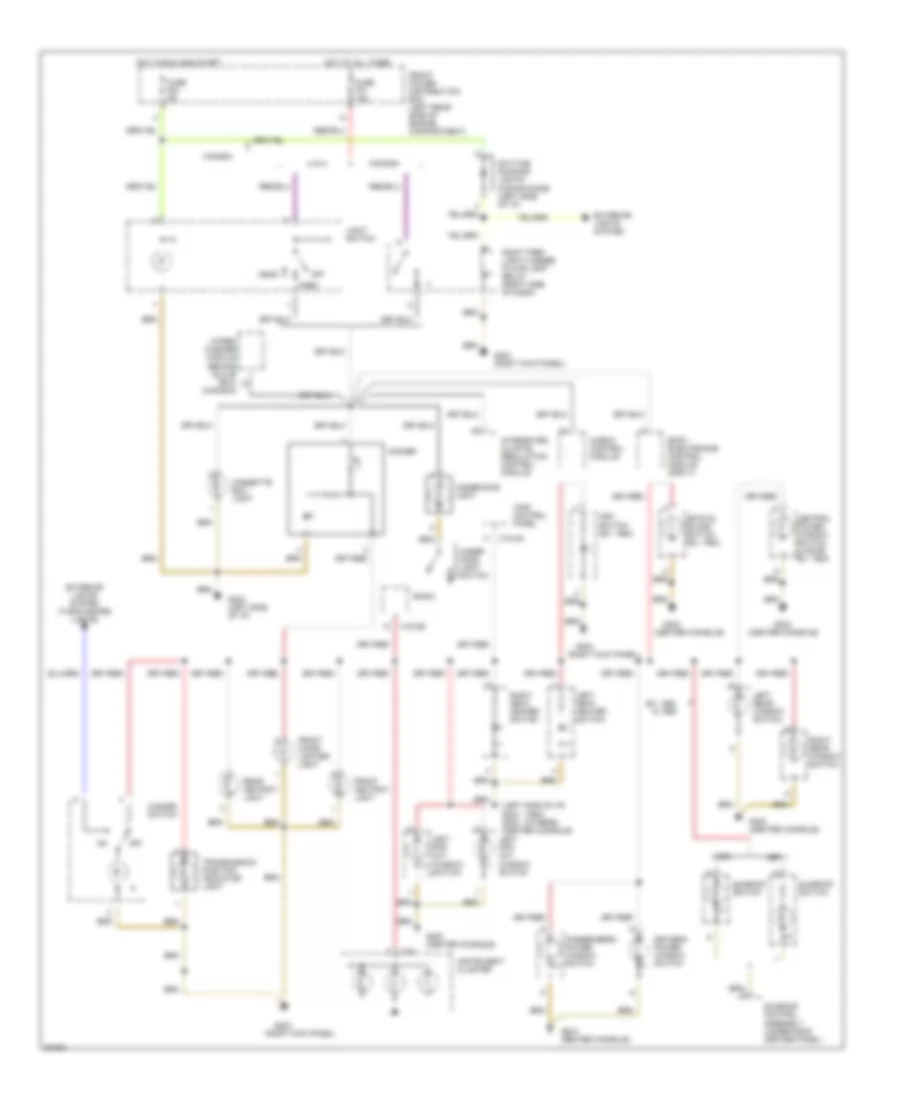
INTERIOR LIGHTS Interior Light Wiring Diagram (1 of 2) for BMW 325i 1994 https://portal-diagnostov.com/license.html
https://portal-diagnostov.com/license.html
Automotive Electricians Portal FZCO
Automotive Electricians Portal FZCO すべての配線図にアクセスする車 List of elements for Interior Light Wiring Diagram (1 of 2) for BMW 325i 1994: (1994) (others) (center console) (left side of i/p) g202 g302 (center console) (right kick panel) Asc switch (ex. 1994) Body electronics control module (zke iv) Canada Cassette box light Central power window switch (2 door, ex. 1994) Check control module Daytime running lights coding diode (left side of i/p) Dimmer Driver's power window switch Ex. 1994 & 1995 Exterior lights system Exterior lights system (turn/hazard lights) Front ashtray light Front cigar lighter light Front power distribution box (left rear side of engine compartment) Fuse f22 5a Fuse f37 10a G202 (left side of i/p) G203 G203 (right kick panel) G302 G302 (center console) Hazard switch Head Hot at all times Hot in run and start Ihkr control panel Instrument cluster Integrated climate regulation control module Left pop out window switch Left rear window switch Left seat heater switch Light switch Off Park Passenger's power window switch Radio Rear ashtray light Right park light/license plate light relay (right side of dash) Right rear window switch Right seat heater switch Spacial sound switch (ex. 1994) Sunroof control assembly (under roof center panel) Sunroof switch Transmission position indicator light U.s.a. Under hood light switch Underhood light Wiper/ washer module (behind glove box) (canada) X16 X18126 X18154
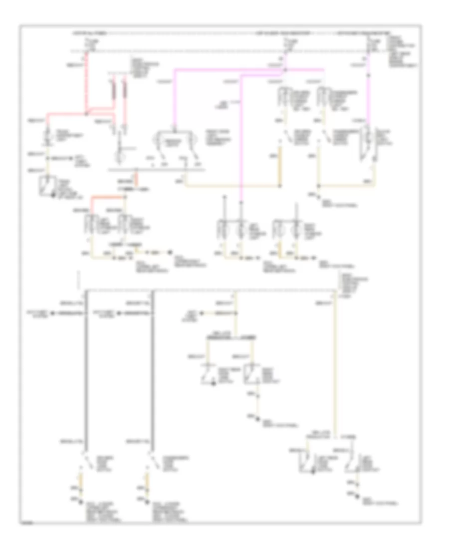
Interior Light Wiring Diagram (2 of 2) for BMW 325i 1994 https://portal-diagnostov.com/license.html
https://portal-diagnostov.com/license.html
Automotive Electricians Portal FZCO
Automotive Electricians Portal FZCO すべての配線図にアクセスする車 List of elements for Interior Light Wiring Diagram (2 of 2) for BMW 325i 1994: (2 door) (4 door) 1994 late production 2 door 4 door Anti- theft system Anti-theft system Body electronics control module (zke iv) Driver's door jamb switch Driver's makeup mirror light (ex. 1997) Driver's makeup mirror switch Front dome light/ map reading assembly Front power distribution box (left rear side of engine compartment) Fuse f33 10a Fuse f43 5a Fuse f44 15a G203 (right kick panel) G310 (upper right rear seatback) G310 (upper right rear seatback) g203 (right kick panel) G312 (upper left rear seatback) G312 (upper left rear seatback) g203 (right kick panel) Glove box light switch Hot at all times Hot in accy, run and start Left rear door contact Left rear door jamb switch Left rear interior light Off Others Passenger's door jamb switch Passenger's makeup mirror light (ex. 1997) Passenger's makeup mirror switch Reading lights Right rear door contact Right rear door jamb switch Right rear interior light Trunk compartment light Trunk light switch (left side of trunk lid) X13254
POWER DOOR LOCKS Power Door Lock Wiring Diagram for BMW 325i 1994 https://portal-diagnostov.com/license.html
https://portal-diagnostov.com/license.html
Automotive Electricians Portal FZCO
Automotive Electricians Portal FZCO すべての配線図にアクセスする車 List of elements for Power Door Lock Wiring Diagram for BMW 325i 1994: 1994-96 Auto int lt sig Body electronics control module (zke iv) (behind glove box) Central arrest sig Central locking switch (from late production 1995) Cerntral lock sig Conn 10182 Conn 13252 Conn 13253 Conn 13254 Conv Convertible top storage lid micro switch Crash sig Data link connector (rear right side of engine compartment) Diag Drive away protect Drivers door lock motor Drivers door lock switch Early production Ex conv From late production Front power distribution box (rear left side of engine compartment) Fuse f35 25a Fuse f7 5a G203 (behind right footwell trim) G312 (in upper left rear seat back) Gas filler lock motor Glove box lock motor Gnd Hot at all times Inertia switch (in lower right "a" pillar) Interior lights system Left rear door lock motor Lk sig drivers door Lk sig passengers door Lk sig trunk lid Lock sig On-board computer (cemter console) Passengers door lock motor Passengers door lock switch Postn sig Pwr lk sig Right rear door lock motor Starter immobilization relay Trunk lid relay (behind glove box) (convertible only) Trunk lid sig (conv) door sig (4 door) Trunk lock motor
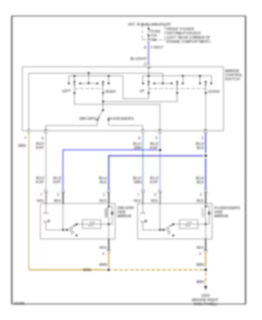
POWER MIRRORS Power Mirror Wiring Diagram for BMW 325i 1994 https://portal-diagnostov.com/license.html
https://portal-diagnostov.com/license.html
Automotive Electricians Portal FZCO
Automotive Electricians Portal FZCO すべての配線図にアクセスする車 List of elements for Power Mirror Wiring Diagram for BMW 325i 1994: Down Driver's Driver's side mirror Front power distribution box (left rear corner of engine compartment) Fuse f24 10a G203 (behind right kick panel) Hot in run and start Left Mirror control switch Nca Passenger's Passenger's side mirror Right X10017
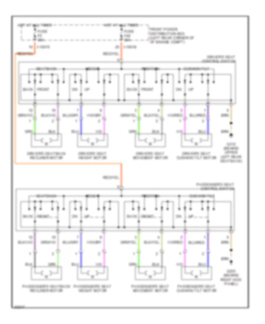
POWER SEATS Driver Power Seat Wiring Diagram for BMW 325i 1994 https://portal-diagnostov.com/license.html
https://portal-diagnostov.com/license.html
Automotive Electricians Portal FZCO
Automotive Electricians Portal FZCO すべての配線図にアクセスする車 List of elements for Driver Power Seat Wiring Diagram for BMW 325i 1994: Back Cushion tilt Driver's seat control switch Driver's seat cushion tilt motor Driver's seat height motor Driver's seat movement motor Driver's seatback recliner motor Front Front power distribution box (left rear corner of of engine compt) Fuse f40 30a Fuse f5 30a G203 (behind right kick panel) G312 (behind upper left rear seatback) Height Hot at all times Passenger's seat control switch Passenger's seat cushion tilt motor Passenger's seat height motor Passenger's seat movement motor Passenger's seatback recliner motor Position Seatback X10015 X10018
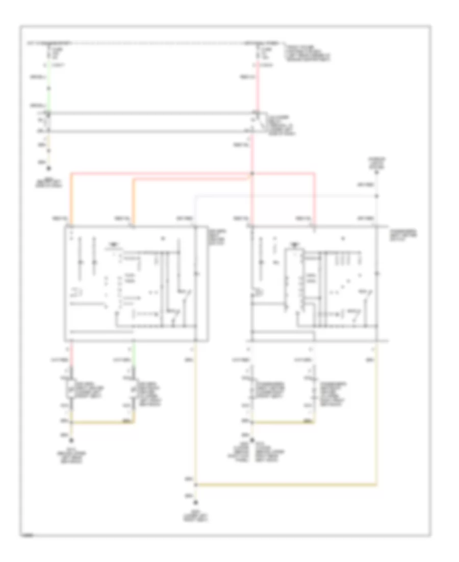
Heated Seats Wiring Diagram for BMW 325i 1994 https://portal-diagnostov.com/license.html
https://portal-diagnostov.com/license.html
Automotive Electricians Portal FZCO
Automotive Electricians Portal FZCO すべての配線図にアクセスする車 List of elements for Heated Seats Wiring Diagram for BMW 325i 1994: Driver's seat heater (under left front seat) Driver's seat heater switch Driver's seatback heater (in upper left front seatback) Front power distribution box (left rear corner of engine compartment) Fuse f23 5a Fuse f4 15a G202 (below left side of dash) G203 (2 door) (behind right kick panel) G300 (under left front seat) G310 (4 door) (behind upper right rear seat back) G312 (behind upper left rear seatback) Hot at all times Hot in run and start Interior lights system Max Min Nca Passenger's seat heater (under right front seat) Passenger's seat heater switch Passenger's seatback heater (in upper right front seatback) Test Unloader relay, terminal 15 (under left side of dash) X10015 X10017
Passenger Power Seat Wiring Diagram for BMW 325i 1994
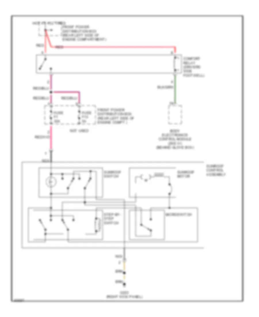
POWER TOP/SUNROOF Sunroof Wiring Diagram for BMW 325i 1994 https://portal-diagnostov.com/license.html
https://portal-diagnostov.com/license.html
Automotive Electricians Portal FZCO
Automotive Electricians Portal FZCO すべての配線図にアクセスする車 List of elements for Sunroof Wiring Diagram for BMW 325i 1994: Body electronics control module (zke iv) (behind glove box) Comfort relay (drivers side footwell) Front power distribution box (rear left side of engine compartment) Front power distribution box (rear left side of engine compt.) Fuse f1 30a Fuse f13 5a G203 (right kick panel) Hot at all times Microswitch Nca Not used Red Step-by- step switch Sunroof control assembly Sunroof motor Sunroof switch
POWER WINDOWS Power Window Wiring Diagram (1 of 2) for BMW 325i 1994 https://portal-diagnostov.com/license.html
https://portal-diagnostov.com/license.html
Automotive Electricians Portal FZCO
Automotive Electricians Portal FZCO すべての配線図にアクセスする車 List of elements for Power Window Wiring Diagram (1 of 2) for BMW 325i 1994: (behind right footwell trim) (behind right footwell trim) (convertible) g203 (console) (convertible) g203 (in upper left rear seat back) (in upper right rear seat back) 2 door or conv Anti-theft control module (behind glove box Body electronics control module (zke iv) (behind glove box) Child protect sig Child protection control (4 door only) Close auto Close sig Close wdo Conn 10182 Conn 13252 Conn 13253 Conn 13254 Conn 13255 Data sig Data sig (conv) close sig (4 door) Data sig (conv) open sig (4 door) Door sig Drivers door jamb switch Drivers power window motor Drivers power window switch Ex 2 door or conv Front power distribution box (rear left side of engine compartment) Fuse f14 30a G203 (behind right footwell trim) G302 (center console near gearshift lever) G303 (ex convertible) G304 (ex convertible) Hot at all times Instrument cluster system Interior lights system Mtr sig Off Open auto Open sig Open wdo Passengers door jamb switch Passengers power window motor Passengers power window switch Revolution sig Starting/charging system Terminal 30h
Power Window Wiring Diagram (2 of 2) for BMW 325i 1994 https://portal-diagnostov.com/license.html
https://portal-diagnostov.com/license.html
Automotive Electricians Portal FZCO
Automotive Electricians Portal FZCO すべての配線図にアクセスする車 List of elements for Power Window Wiring Diagram (2 of 2) for BMW 325i 1994: 4 door Auto close Auto open Central power window switch (convertible only) Close Close wdo Convertible Copy Front power distribution box (rear left side of engine compartment) Fuse f19 30a G203 (behind right footwell trim) G302 (center console, near gearshift lever) Ground Hot at all times Interior lights system Left rear door (console) power window switch (4 door) left rear power window switch (convertible) Left rear door (door) power window switch (4 door only) Left rear window motor Off Open Open wdo Relay module (behind glove box) Right rear door (console) power window switch (4 door) right rear power window switch (convertible) Right rear door (door) power window switch (4 door only) Right rear window motor
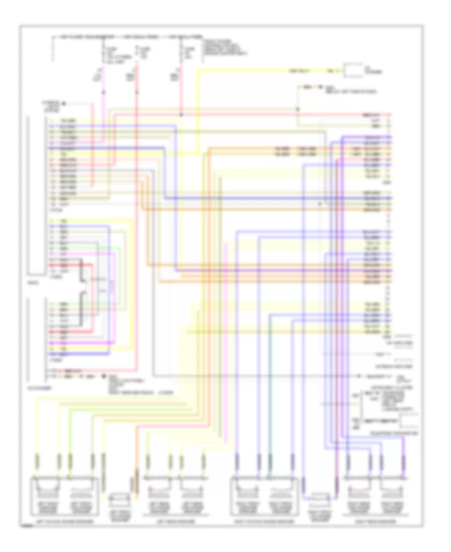
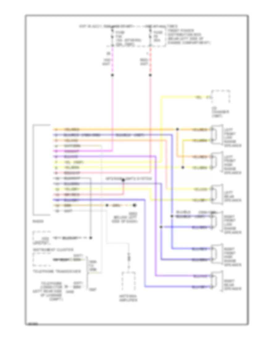
RADIO Radio Wiring Diagrams, 10 Speaker System for BMW 325i 1994 https://portal-diagnostov.com/license.html
https://portal-diagnostov.com/license.html
Automotive Electricians Portal FZCO
Automotive Electricians Portal FZCO すべての配線図にアクセスする車 List of elements for Radio Wiring Diagrams, 10 Speaker System for BMW 325i 1994: (1994-1996) (1997 only) (1997) (4 door) (others) 20a Antenna amplifier Cd changer Connector x400 (left rear side of luggage compt) Front power distribution box (rear left side of engine compartment) Fuse f33 10a Fuse f44 15a Fuse f9 20a G202 (below left side of dash) G203 (right kick panel) (2 door) g310 (right rear seatback) Hifi amplifier Hot at all times Hot in accy, run and start Instrument cluster Interior lights system Left front high range speaker Left front low range speaker Left front midrange speaker Left mid-high range speaker Left rear high range speaker Left rear low range speaker Left rear speaker Nca Radio Red Right front high range speaker Right front low range speaker Right front midrange speaker Right mid-high range speaker Right rear high range speaker Right rear low range speaker Right rear speaker Telephone Telephone transceiver Vss output X18126 X18520 X605 X606
Radio Wiring Diagrams, 6 Speaker System for BMW 325i 1994 https://portal-diagnostov.com/license.html
https://portal-diagnostov.com/license.html
Automotive Electricians Portal FZCO
Automotive Electricians Portal FZCO すべての配線図にアクセスする車 List of elements for Radio Wiring Diagrams, 6 Speaker System for BMW 325i 1994: (1994-1996) (1997) (others) (1997) Antenna amplifier Cd changer (1997) Front power distribution box (rear left side of engine compartment) Fuse f44 15a 20a Fuse f9 20a G202 (below left side of dash) Hot at all times Hot in accy, run and start Instrument cluster Interior lights system Left front high range speaker Left front low range speaker Left rear speaker Of luggage compt) Radio Right front high range speaker Right front low range speaker Right rear speaker Telephone connector (left rear side x400 Telephone transceiver Vss output
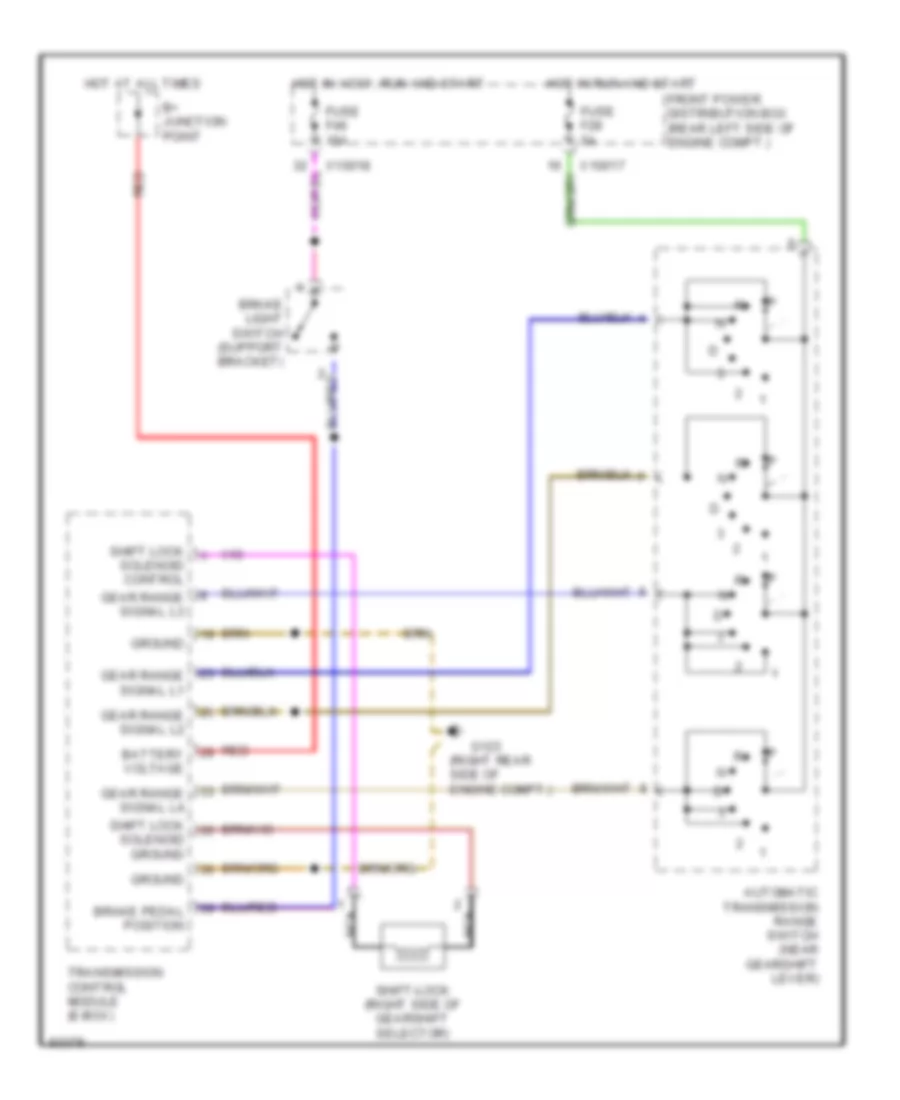
SHIFT INTERLOCKS Shift Interlock Wiring Diagram for BMW 325i 1994 https://portal-diagnostov.com/license.html
https://portal-diagnostov.com/license.html
Automotive Electricians Portal FZCO
Automotive Electricians Portal FZCO すべての配線図にアクセスする車 List of elements for Shift Interlock Wiring Diagram for BMW 325i 1994: (right rear side of engine compt.) Automatic transmission range switch (near gearshift lever) B+ junction point Battery voltage Brake light switch (support bracket) Brake pedal position Front power distribution box (rear left side of engine compt.) Fuse f28 5a Fuse f46 15a G123 Gear range signal l1 Gear range signal l2 Gear range signal l3 Gear range signal l4 Ground Hot at all times Hot in accy, run and start Hot in run and start Nca Red Shift lock solenoid control Shift lock solenoid ground Shift-lock (right side of gearshift selector) Transmission control module (e-box) X10017 X10018
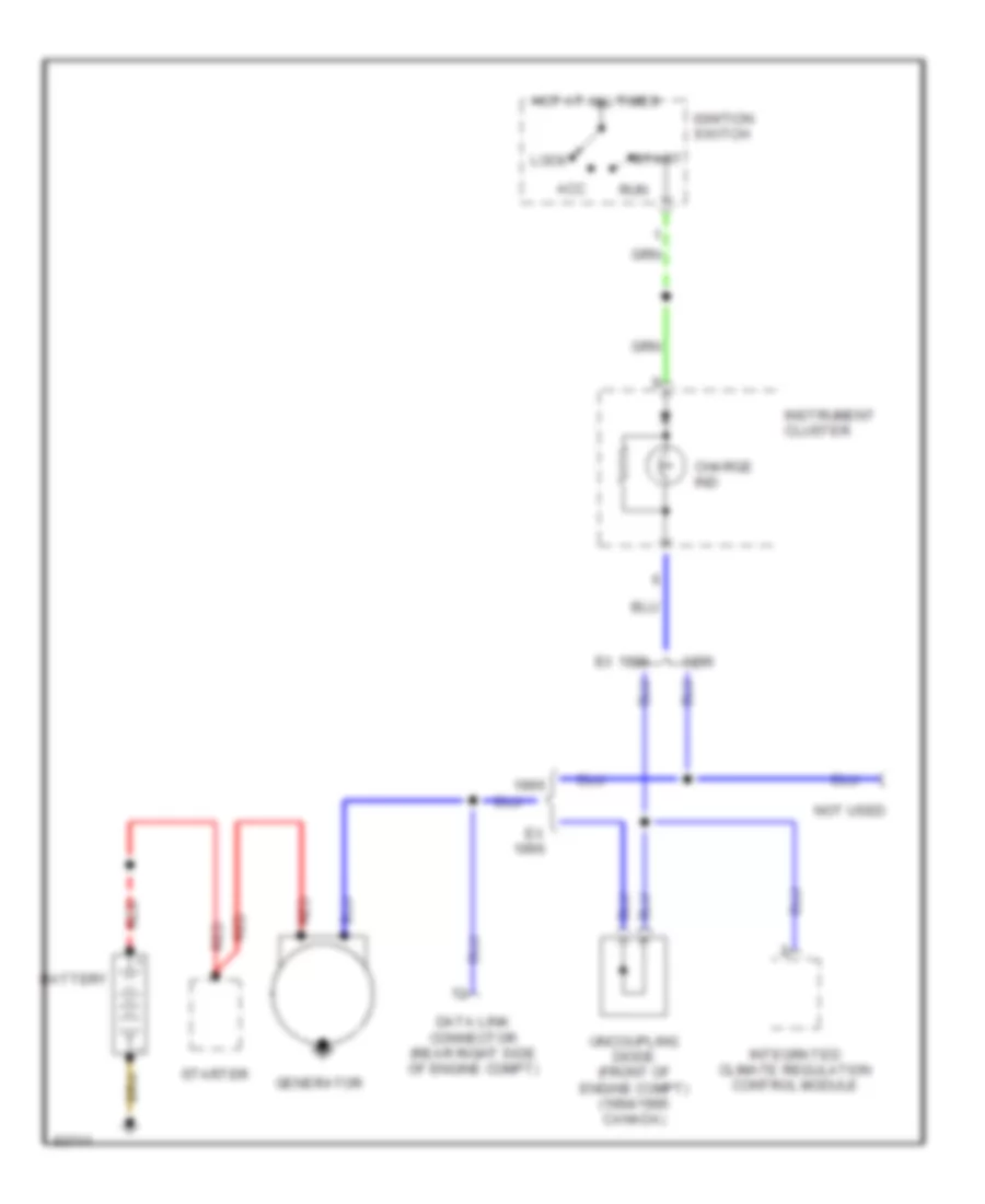
STARTING/CHARGING Charging Wiring Diagram for BMW 325i 1994 https://portal-diagnostov.com/license.html
https://portal-diagnostov.com/license.html
Automotive Electricians Portal FZCO
Automotive Electricians Portal FZCO すべての配線図にアクセスする車 List of elements for Charging Wiring Diagram for BMW 325i 1994: Acc Battery Charge ind Data link connector (rear right side of engine compt) Ex 1996 Generator Hot at all times Ignition switch Instrument cluster Integrated climate regulation control module Lock Not used Red Run Start Starter Uncoupling diode (front of engine compt) (1994/1995 canada)
Starting Wiring Diagram, Early Production for BMW 325i 1994 https://portal-diagnostov.com/license.html
https://portal-diagnostov.com/license.html
Automotive Electricians Portal FZCO
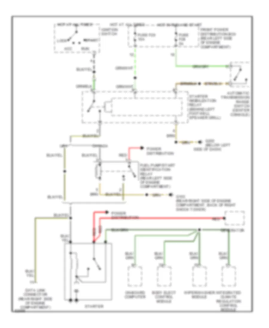
Automotive Electricians Portal FZCO すべての配線図にアクセスする車 List of elements for Starting Wiring Diagram, Early Production for BMW 325i 1994: Acc Automatic transmission range switch (center console) Body elect control module Data link connector (rear right side of engine compartment) Ex m3 canada Front power distribution box (rear left side of engine compartment) Fuel pump/start identification relay (rear left side of engine compartment) Fuse f28 5a G202 (below left Generator Hot at all times Hot in run and start Ignition switch Integrated climate regulation control module Lock M3 canada On-board computer Power distribution Red Run Side of dash) Start Starter Starter relay (behind left footwell speaker grill) W/ egs W/o egs Wiper/washer module
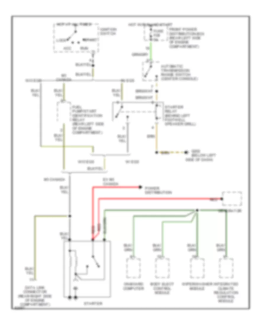
Starting Wiring Diagram, Late Production for BMW 325i 1994 https://portal-diagnostov.com/license.html
https://portal-diagnostov.com/license.html
Automotive Electricians Portal FZCO
Automotive Electricians Portal FZCO すべての配線図にアクセスする車 List of elements for Starting Wiring Diagram, Late Production for BMW 325i 1994: Acc Automatic transmission range switch (center console) Body elect control module Canada Data link connector (rear right side of engine compartment) Front power distribution box (rear left side of engine compartment) Fuel pump/start identification relay (rear left side of engine compartment) Fuse f26 10a Fuse f28 5a G103 (rear right side of engine compartment, back of right shock tower) G202 (below left Generator Hot at all times Hot in run and start Ignition switch Integrated climate regulation control module Lock On-board computer Power distribution Red Run Side of dash) Start Starter Starter imobilization relay (behind left footwell speaker grill) Usa Wiper/washer module
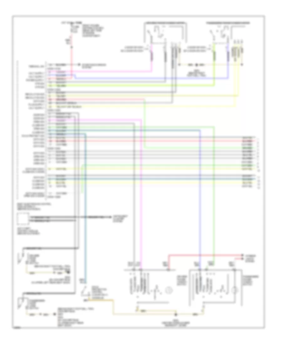
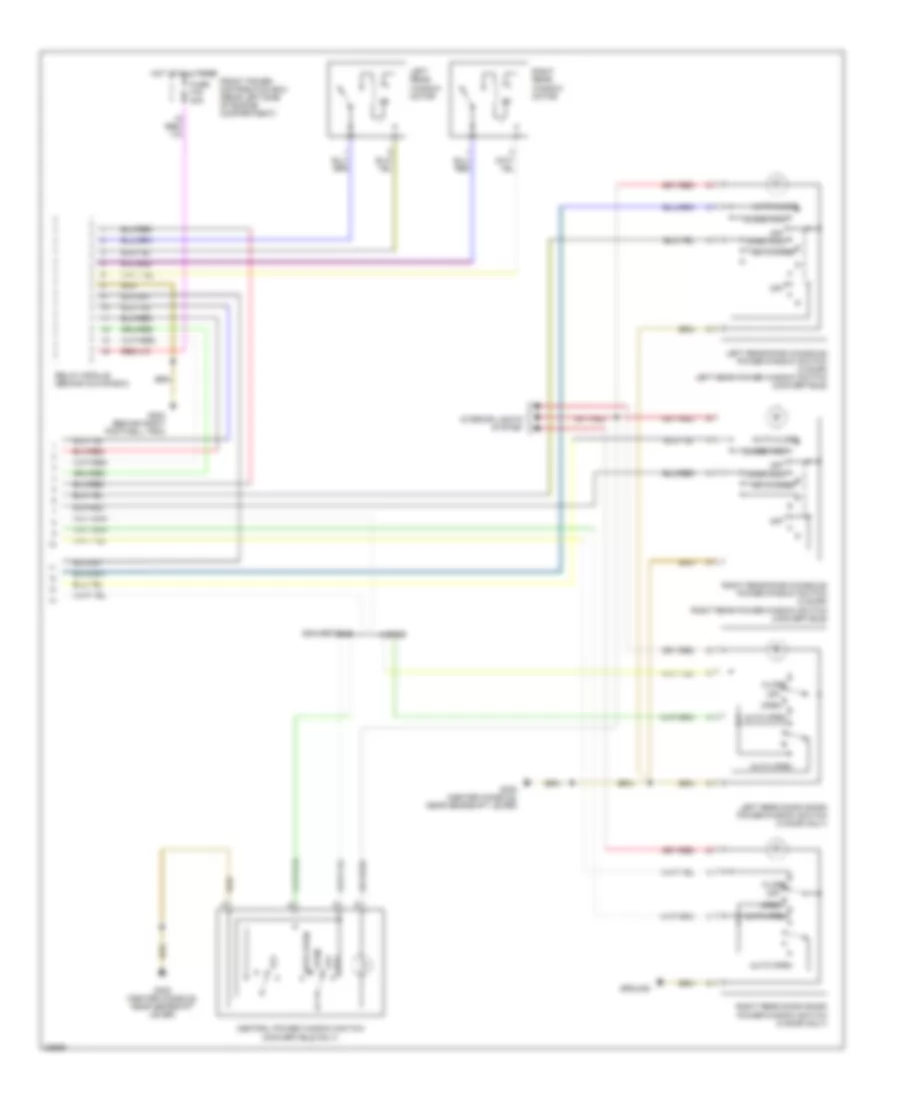
TRANSMISSION Transmission Wiring Diagram for BMW 325i 1994 https://portal-diagnostov.com/license.html
https://portal-diagnostov.com/license.html
Automotive Electricians Portal FZCO
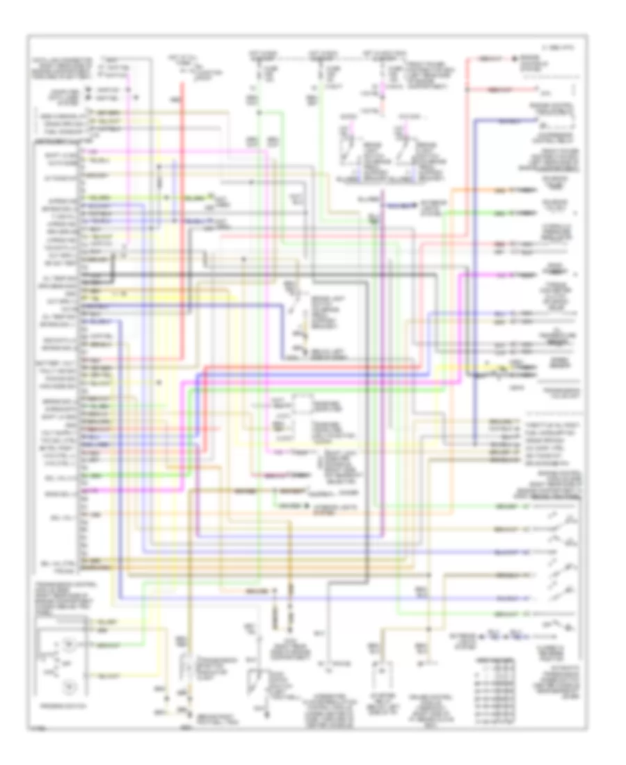
Automotive Electricians Portal FZCO すべての配線図にアクセスする車 List of elements for Transmission Wiring Diagram for BMW 325i 1994: (behind right footwell trim) (below left side of dash) (not used) x69 87a A-prog ind A/c comp. ctrl. Auto Automatic transmission range switch (center console near gearshift lever) B+ junction point Band sol (+) Band solenoid Battery volt Bk pdl posit. Bk sw test Brake light switch (on brake pedal support bracket) Brake light switch (on brake pedal support bracket) C 1995 vftc Closed in reverse position Clr Compressor control relay Computer data lines system Crank rpm sig. Cruise control module (tempomat) (right side of i/p, behind glove box) Data link connector (right rear side of engine compartment, forward of battery) Dimmer Drive range p/n Egs a4s 310r Egs warning lp Engine control module (dme) (right rear side of engine compartment in e-box behind trim panel) Engine control module relay Engine controls system Exterior lights system Fault ind sig Front power distribution box (left rear side of engine compartment) Fuel consump. Fuel consumption Fuse f26 10a Fuse f28 5a Fuse f46 15a G123 (right rear side of engine compartment) G200 G201 Gnd Gr rng sig l1 Gr rng sig l2 Gr rng sig l3 Gr rng sig l4 Hot at all times Hot in accy,run & start Hot in run & start Hyd ctrl (+) Hyd ctrl (-) Hydraulic pressure regulator Ig timing int Ign timing int. Instrument cluster Integrated climate regulation control module (under center of dash, forward of center console) Interior lights system Kick down switch (left footwell) Kick-dn sig M-prog ind Man Man mode sig Nca Off Oil temp sig Oil temperature sensor On-board computer On-board computer (multifunction clock) Out spd (+) Out spd (-) Output Program switch Red Rpm spd sig Rxd data lk S-prog btn S-prog ind Shift lk gnd Shift lk sol auto mode Shift lock (center console, right side of gearshift selector) Sol val 1 Sol val 2 (+) Sol val ctrl Solenoid valve 1 Solenoid valve 2 Spd sens shd Speed sensor Starter relay (below left side of i/p) Tcc sol ctrl Throttle val posit. Ti sig (fl) Torque converter clutch solenoid valve Tps sig Transmission control module (egs) (right rear side of engine compartment in e-box behind trim panel) Transmission position indicator light Transmission valve unit Txd data lk W/ccm W/o ccm X10017 X10018 X1070 X1071 X16 X18155 X8516 X8521
WIPER/WASHER Headlamp/Foglamp Washer Wiring Diagram, USA for BMW 325i 1994
Jet Heater Wiring Diagram for BMW 325i 1994
Wiper/Washer Wiring Diagram, USA for BMW 325i 1994
Wiper/Washer/Headlamp Washer Wiring Diagram for BMW 325i 1994 https://portal-diagnostov.com/license.html
https://portal-diagnostov.com/license.html
Automotive Electricians Portal FZCO
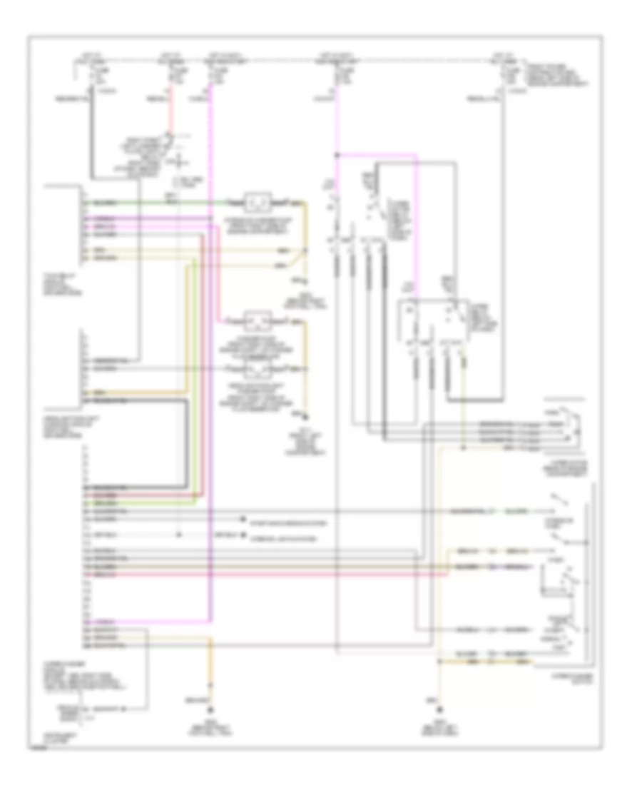
Automotive Electricians Portal FZCO すべての配線図にアクセスする車 List of elements for Wiper/Washer/Headlamp Washer Wiring Diagram for BMW 325i 1994: (ex 1992) (1992) 85b 87a 87b Fast Front power distribution box (rear left side of engine compartment) Fuse f3 30a Fuse f36 30a Fuse f37 10a Fuse f44 15a Fuse f45 7.5a G111 (front left side of engine compartment) G202 (below left side of dash) G203 (behind right footwell trim) Headlight/foglight cleaning module (footwell, driver's side) Headlight/foglight washer pump (front right side of engine compt, on washer fluid reservoir) Hot at all times Hot in accy, run and start Instrument cluster Intensive wash Intensive washer pump (front right side of engine compartment) Inter Interior lights system Nca Normal Off Park Right park light/license plate light relay (right side of dash, behind glove box) Run Single Starting/charging system Twin relay module (footwell, driver's side) Vehicle speed signal Wash Washer pump (front right side of engine compt, on washer fluid reservoir) Wiper motor (rear of engine compartment) Wiper motor relay (below left side of dash) Wiper relay (below left side of dash) Wiper/washer module (except 1992: right side of dash, behind glove box; 1992: driver's side footwell) Wiper/washer switch X10015 X10018 X17

 Čeština
 Dansk
Dansk Deutsch
 Ελληνικά
 English
 English
 Español
 Suomi
Suomi Français
 Français
 עברית
עברית Hrvatski
 Magyar
 Italiano
 한국어
한국어 Nederlands
 Polski
 Português
 Português
 Română
 Русский
 Slovenčina
 Slovenščina
 Svenska
 Türkçe
 中文 (中国)