AIR CONDITIONING
Automatic A/C Wiring Diagram for Chevrolet Corvette 1999
 https://portal-diagnostov.com/license.html
Automotive Electricians Portal FZCO
Automotive Electricians Portal FZCO
https://portal-diagnostov.com/license.html
https://portal-diagnostov.com/license.html
Automotive Electricians Portal FZCO
Automotive Electricians Portal FZCO
List of elements for Automatic A/C Wiring Diagram for Chevrolet Corvette 1999:
- (base of right "a" pillar)
- (base of right "a" pillar) g203
- (in i/p harness) star connector 1
- +5v
- A/c clu micro relay
- A/c compressor clutch
- A/c diode
- A/c mini fuse 24 10a
- A/c on
- A/c refrigerant pressure sensor (attached to the a/c high side line)
- A/c solenoid
- Act pos in
- All times
- Ambient outside temperature sensor (right front of engine compt)
- Battery
- Bi-lev solenoid
- Blo mot maxi fuse 51 30a
- Blo spd
- Blower motor control module (behind right side of dash)
- C10
- C11
- C12
- C13
- Cool fan 1 maxi fuse 49 30a
- Cool fan 1 mini relay
- Cool fan 2 maxi fuse 46 30a
- Cool fan 2 mini relay
- Cool fan 3 mini fuse 14 10a
- Cool fan 3 mini relay
- D10
- D11
- D12
- D13
- Data line
- Data link connector (under dash, below steering column)
- Defrost solenoid
- G105 (rear of right front wheel- house)
- G105 (rear of right front wheelhouse)
- G203
- Ground
- Heater solenoid
- Hot at
- Hot at all times
- Hot in run
- Hot in run or start
- Hvac con mini fuse 27 10a
- Hvac control head
- Hvac mini fuse 18 10a
- Ign
- Inside air temperature sensor (in air outlet, right of steering column)
- Inside temp
- Instrument panel electrical center
- Left electric actuator
- Left engine cooling fan motor
- Motor drive
- Nca
- Outside temp
- Pnk
- Powertrain control module (right side of engine compt)
- Pres sig
- Recirc solenoid
- Red
- Relay ctrl
- Right electric actuator
- Right engine cooling fan motor
- S201 (i/p harness, 30 cm from hvac control head)
- S215
- Sens gnd
- Sens ground
- Serial data
- Sol 1 ctrl
- Sol 2 ctrl
- Sol 3 ctrl
- Sol 4 ctrl
- Sol 5 ctrl
- Solid state
- Sunload in
- Sunload temperature sensor (top of dash, left side of defroster grille)
- Tan
- Underhood electrical center
- Vacuum/electric solenoid
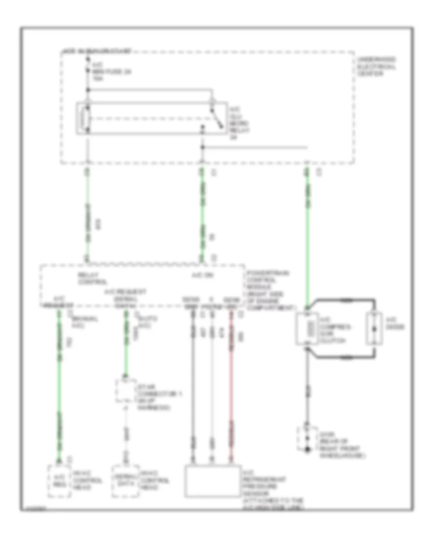
Compressor Wiring Diagram for Chevrolet Corvette 1999
 https://portal-diagnostov.com/license.html
Automotive Electricians Portal FZCO
Automotive Electricians Portal FZCO
https://portal-diagnostov.com/license.html
https://portal-diagnostov.com/license.html
Automotive Electricians Portal FZCO
Automotive Electricians Portal FZCOList of elements for Compressor Wiring Diagram for Chevrolet Corvette 1999:
- (auto c1 a/c)
- (manual c2 a/c)
- A/c clu micro relay
- A/c compres- sor clutch
- A/c diode
- A/c mini fuse 24 10a
- A/c on
- A/c refrigerant pressure sensor (attached to the a/c high side line)
- A/c req
- A/c request
- A/c request (serial data)
- D12
- G105 (rear of right front wheelhouse)
- Hot in run or start
- Hvac control head
- Nca
- Powertrain control module (right side of engine compartment)
- Relay control
- Sens grd
- Sens sig
- Serial data
- Star connector 1 (in i/p harness)
- Underhood electrical center
- Volts
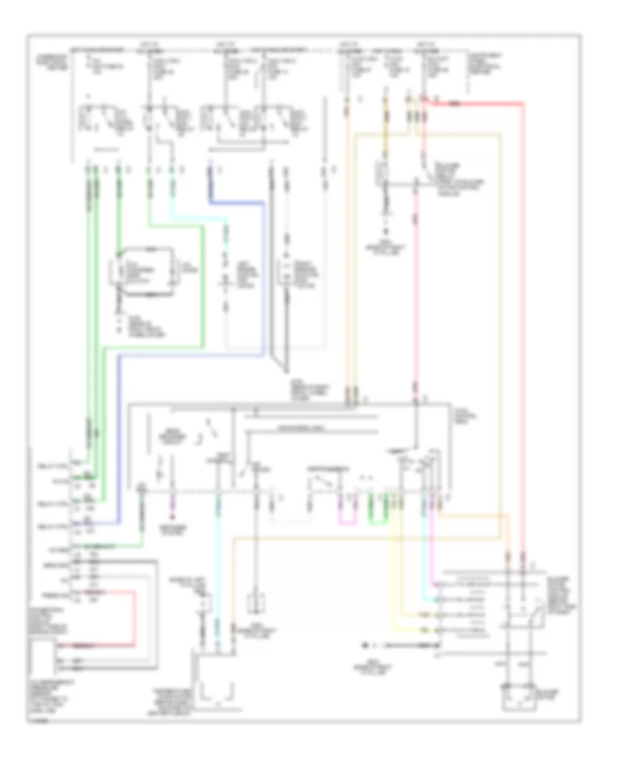
Manual A/C Wiring Diagram for Chevrolet Corvette 1999
 https://portal-diagnostov.com/license.html
Automotive Electricians Portal FZCO
Automotive Electricians Portal FZCO
https://portal-diagnostov.com/license.html
https://portal-diagnostov.com/license.html
Automotive Electricians Portal FZCO
Automotive Electricians Portal FZCOList of elements for Manual A/C Wiring Diagram for Chevrolet Corvette 1999:
- (base of left "a" pillar) g200
- +5v
- A c2
- A/c clu micro relay
- A/c compres- sor clutch
- A/c diode
- A/c mini fuse 24 10a
- A/c on
- A/c refrigerant pressure sensor (attached to the a/c high side line)
- A/c req
- Air recirc
- Air source logic
- All times
- Blo mot maxi fuse 49 30a
- Blower motor
- Blower motor control module (behind right side of dash)
- Blower motor relay (part of blower motor control module)
- Cool fan 1 maxi fuse 49 30a
- Cool fan 1 mini relay
- Cool fan 2 maxi fuse 46 30a
- Cool fan 2 mini relay
- Cool fan 3 mini fuse 14 10a
- Cool fan 3 mini relay
- Defogger system
- Defrost/defog
- G tan
- G105 (rear of right front wheel- house)
- G105 (rear of right front wheelhouse)
- G203 (base of right "a" pillar)
- Hot at
- Hot in run
- Hot in run or start
- Hvac mini fuse 18 10a
- Hvac con mini fuse 27 10a
- Hvac control head
- Instrument panel electrical center
- Left engine cooling fan motor
- Nca
- Off
- Powertrain control module (right side of engine compt)
- Press sig
- Rear defogger circuit
- Red
- Relay ctrl
- Right engine cooling fan motor
- Sens gnd
- Tan
- Temp control
- Temperature door motor (behind dash, mounted on heater plenum)
- Underhood electrical center
ANTI-LOCK BRAKES
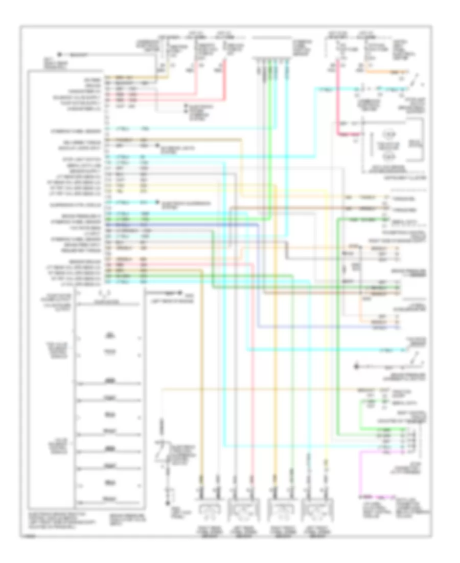
Anti-lock Brake Wiring Diagrams, with Active Handling for Chevrolet Corvette 1999
 https://portal-diagnostov.com/license.html
Automotive Electricians Portal FZCO
Automotive Electricians Portal FZCO
https://portal-diagnostov.com/license.html
https://portal-diagnostov.com/license.html
Automotive Electricians Portal FZCO
Automotive Electricians Portal FZCOList of elements for Anti-lock Brake Wiring Diagrams, with Active Handling for Chevrolet Corvette 1999:
- (i/p harn, 6.5 cm from body control module)
- (left rear of engine)
- A11
- A13
- Abs maxi fuse 52 40a
- Abs/rtd elec maxi fuse 53 20a
- Abstrns fuse 1 10a
- Antilock brake system indicator
- Back-up lamps input
- Body control module (mounted on toe board)
- Brake pres input
- Brake pressure differential switch
- Brake pressure in
- Brake pressure modulator valve (bpmv)
- Brake pressure sensor
- D15
- Data link connector (under dash below steering column)
- Delivered torque
- Electronic brake traction control module (ebtcm) (left front side of engine compt, mounted on frame rail)
- Electronic power steering system
- Electronic suspension system
- Electronic traction/ suspension control switch
- Exterior lights system
- G200 (left kick panel)
- G402
- G417 (right rear frame rail)
- Ground
- Hot at all times
- Hot in on or start
- Hot in run
- Ign feed
- Instru- ment panel electrical center
- Instrument cluster
- Ipc mini fuse 10a
- Iso
- La input
- Lateral accelerometer
- Left front wheel speed sensor
- Left rear wheel speed sensor
- Lf in
- Lf out
- Lf whl spd sens (hi)
- Lft frt whl spd sens (lo)
- Lft rear spd sens (hi)
- Lft rear whl spd sens (lo)
- Lr in
- Lr out
- Magnasteer (hi)
- Magnasteer (lo)
- Nca
- Pnk
- Powertrain control module (right side of engine compt)
- Prime
- Pump motor
- Pump motor power output
- Red
- Requested torque
- Rf in
- Rf out
- Right front wheel speed sensor
- Right rear wheel speed sensor
- Rr in
- Rr out
- Rt frt whl spd sens (hi)
- Rt frt whl spd sens (lo)
- Rt rear whl spd sens (hi)
- Rt rear whl spd sens (lo)
- S106
- S108
- S206
- S308
- S310
- Sensor ground
- Serial data
- Serial data line
- Solid state
- Star connector 1 (in i/p harness)
- Steering wheel position sensor
- Steering wheel sensor
- Stop light switch
- Stoplamp switch (brake pedal support)
- Stp/haz maxi fuse 20a
- Suspension ctrl module
- Tan
- Tcs active indicator
- Tcs valve solenoid control signals
- Torque del
- Torque req
- Traction on/off
- Underhood electrical center
- Valve power output
- Valve solenoid control signals
- Yaw rate sens
- Yaw rate sensor
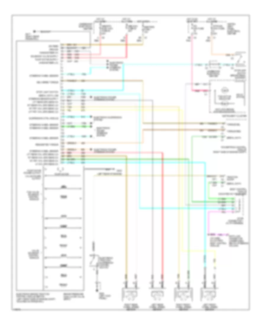
Anti-lock Brake Wiring Diagrams, without Active Handling for Chevrolet Corvette 1999
 https://portal-diagnostov.com/license.html
Automotive Electricians Portal FZCO
Automotive Electricians Portal FZCO
https://portal-diagnostov.com/license.html
https://portal-diagnostov.com/license.html
Automotive Electricians Portal FZCO
Automotive Electricians Portal FZCOList of elements for Anti-lock Brake Wiring Diagrams, without Active Handling for Chevrolet Corvette 1999:
- (i/p harn, 6.5 cm from body control module)
- (left rear of engine)
- A11
- A13
- Abs maxi fuse 52 40a
- Abs/rtd elec maxi fuse 53 20a
- Abstrns fuse 1 10a
- Antilock brake system indicator
- Body control module (mounted on toe board)
- Brake pressure modulator valve (bpmv)
- D15
- Data link connector (under dash below steering column)
- Delivered torque
- Electronic brake traction control module (ebtcm) (left front side of engine compt, mounted on frame rail)
- Electronic power steering system
- Electronic suspension system
- Electronic traction/ suspension control switch
- G200 (left kick panel)
- G402
- G417 (right rear frame rail)
- Ground
- Hot at all times
- Hot in on or start
- Hot in run
- Ign feed
- Instru- ment panel electrical center
- Instrument cluster
- Ipc mini fuse 10a
- Iso
- Left front wheel speed sensor
- Left rear wheel speed sensor
- Lf in
- Lf out
- Lf whl spd sens (hi)
- Lft frt whl spd sens (lo)
- Lft rear spd sens (hi)
- Lft rear whl spd sens (lo)
- Lr in
- Lr out
- Magnasteer (hi)
- Magnasteer (lo)
- Nca
- Pnk
- Powertrain control module (right side of engine compt)
- Prime
- Pump motor
- Pump motor power output
- Red
- Requested torque
- Rf in
- Rf out
- Right front wheel speed sensor
- Right rear wheel speed sensor
- Rr in
- Rr out
- Rt frt whl spd sens (hi)
- Rt frt whl spd sens (lo)
- Rt rear whl spd sens (hi)
- Rt rear whl spd sens (lo)
- S206
- Serial data
- Serial data line
- Solid state
- Star connector 1 (in i/p harness)
- Steering wheel sensor
- Stop light switch
- Stoplamp switch (brake pedal support)
- Stp/haz maxi fuse 20a
- Suspension ctrl module
- Tan
- Tcs active indicator
- Tcs valve solenoid control signals
- Torque del
- Torque req
- Traction on/off
- Underhood electrical center
- Valve power output
- Valve solenoid control signals
ANTI-THEFT
Anti-theft Wiring Diagram for Chevrolet Corvette 1999
 https://portal-diagnostov.com/license.html
Automotive Electricians Portal FZCO
Automotive Electricians Portal FZCO
https://portal-diagnostov.com/license.html
https://portal-diagnostov.com/license.html
Automotive Electricians Portal FZCO
Automotive Electricians Portal FZCOList of elements for Anti-theft Wiring Diagram for Chevrolet Corvette 1999:
- A/t
- A11
- A13
- Accy
- B10
- Body control module (mounted on the toe board, in right front footwell)
- Bulb test
- C13
- C14
- Clutch pedal switch (top of clutch pedal)
- Convertible
- Crk fuse 14 10a
- D16
- Driver door module (bottom of left door)
- Driver dr ajar
- Exterior lights system (back-up lights circuit)
- Exterior lights system (drl relays)
- F/tnkdr fuse 32 15a
- F12
- Fog lamp switch/ rear compartment lid release switch
- Folding top ajar indicator switch
- G200
- G202
- G203
- G413
- Ground
- Horn rly
- Horns system (horn relay)
- Hot at all times
- Hot in on and start
- Ignition key
- Ignition key lock cylinder
- Ignition switch
- Instrument panel cluster (ipc)
- Instrument panel fuse block
- Instrument panel fuse block (in right front footwell, mounted to toe board)
- Ipc fuse 10a
- Key in
- Key out
- Key sw in
- Left door ajar indicator switch
- Left door key switch
- Lock
- Lt door ajar
- Lt drl rly
- M/t
- Nca
- Off
- Park/neutral position switch (left side of transmission)
- Pass dr ajar
- Pass key rtn
- Pass-key in
- Passenger door module (bottom of right door)
- Per/mlp rly
- Pnk
- Powertrain control module (right side of engine compt)
- Red
- Resistor pellet
- Right door ajar indicator switch
- Right door key switch
- Rr compt rel
- Rt door ajar
- Rt drl rly
- Run
- S210 (i/p harn, right of blower motor control module breakout)
- Security indicator
- Serial data
- Splice pack 201 (left kick panel)
- Splice pack 202 (left kick panel)
- Splice pack 202 (right kick panel)
- Splice pack 302 (front of right quarter panel)
- Star connector 1 (in instrument panel harness)
- Start
- Starter enable
- Starter maxifuse 60a
- Starting/ charging system (starter)
- Tan
- Theft deterrent relay (in right footwell, above bcm)
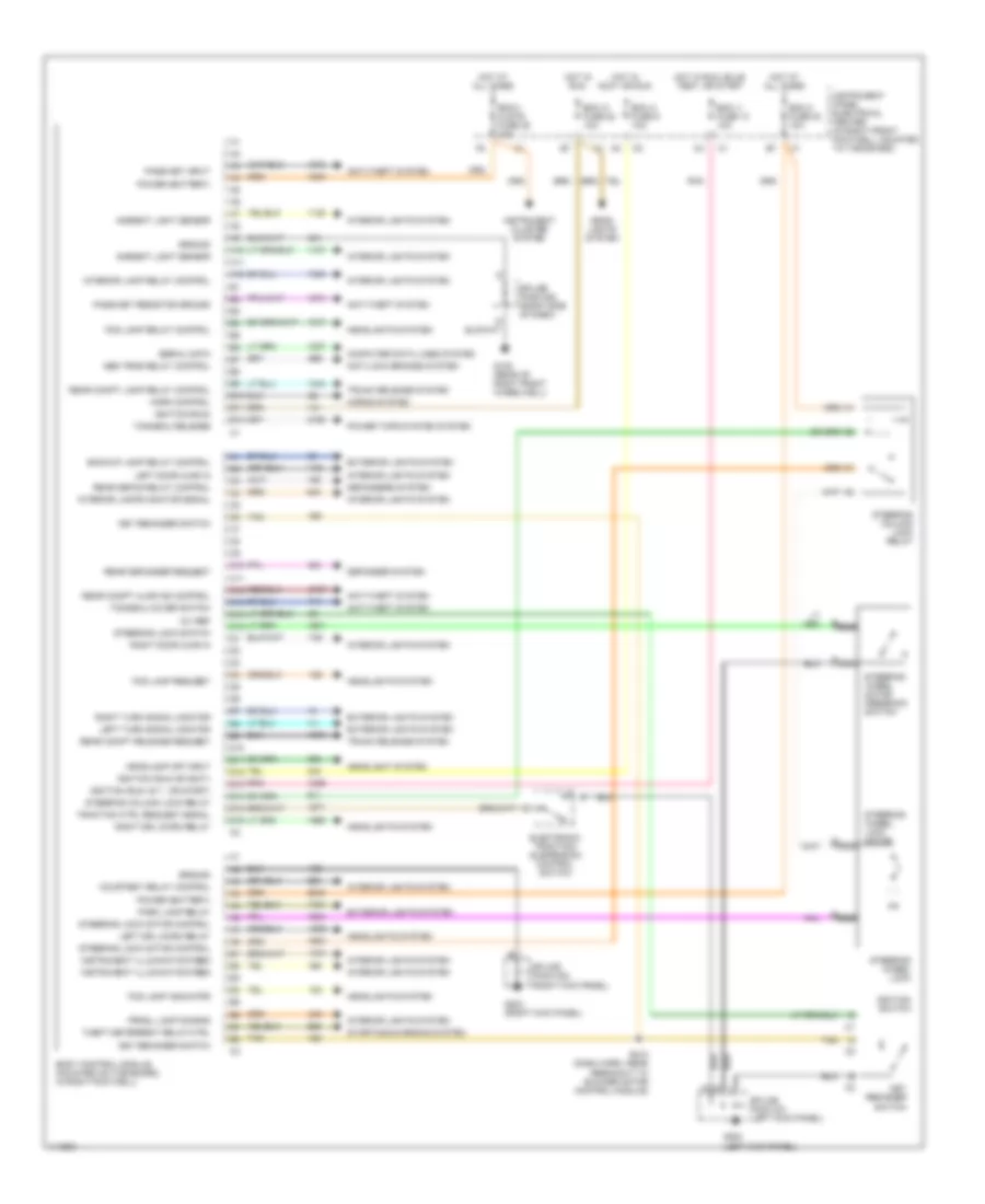
BODY COMPUTER
Body Computer Wiring Diagrams for Chevrolet Corvette 1999
 https://portal-diagnostov.com/license.html
Automotive Electricians Portal FZCO
Automotive Electricians Portal FZCO
https://portal-diagnostov.com/license.html
https://portal-diagnostov.com/license.html
Automotive Electricians Portal FZCO
Automotive Electricians Portal FZCOList of elements for Body Computer Wiring Diagrams for Chevrolet Corvette 1999:
- 12v ref
- A10
- A11
- A12
- Abs trns relay control
- Ambient light sensor
- Anti-lock brakes system
- Anti-theft system
- B10
- B11
- B12
- Backup lamp relay control
- Bcm 2 fuse 23 10a
- Bcm a fuse 9 10a
- Bcm i1 fuse 13 10a
- Bcm i3 fuse 22 10a
- Bcm1/ clstr fuse 25 10a
- Body control module (mounted on toe board, in right footwell)
- C10
- C11
- C12
- C13
- C14
- C15
- Computer data lines system
- Courtesy relay control
- D10
- D11
- D12
- D13
- D14
- D15
- D16
- Defogger system
- Defoggers system
- Electronic traction/ suspension control switch
- Exterior lights system
- Fog lamp indicator
- Fog lamp relay control
- Fog lamp request
- G105 (rear of right front wheelwell)
- G200 (left kick panel)
- G203 (right kick panel)
- Ground
- Head- lights system
- Headlamp off input
- Headlight system
- Headlights system
- Horn control
- Horns system
- Hot at all times
- Hot in accy or run
- Hot in run
- Hot in run, bulb test, or start
- Ignition (run or accy)
- Ignition (run)
- Ignition (run, b.t., or start)
- Ignition switch
- Instrument cluster system
- Instrument illumination feed
- Instrument panel electrical center (in right front footwell, mounted to toe board)
- Interior lamp relay control
- Interior lamps monitor signal
- Interior lights system
- Key reminder switch
- Left door ajar in
- Left drl micro relay
- Left turn signal monitor
- Nca
- Park lamp relay
- Pass-key input
- Pass-key resistor ground
- Pnk
- Power (battery)
- Power tops system system
- Prndl lamp dimming
- Rear compt ajar ind control
- Rear compt lamp relay control
- Rear compt release request
- Rear defog relay control
- Rear defogger request
- Right door ajar in
- Right drl micro relay
- Right turn signal monitor
- S210 (dash harn, near breakout to blower motor control module)
- Serial data
- Splice pack 201 (left kick panel)
- Splice pack 202 (right kick panel)
- Splice pack 208 (right side of dash)
- Starting/charging system
- Steering column lock relay
- Steering lock motor control
- Steering lock switch
- Steering wheel lock
- Steering wheel lock motor
- Steering wheel motor feedback switch
- Tan
- Theft deterrent relay ctrl
- Tonneau cover switch
- Tonneau release
- Traction ctrl request signal
- Trunk release system
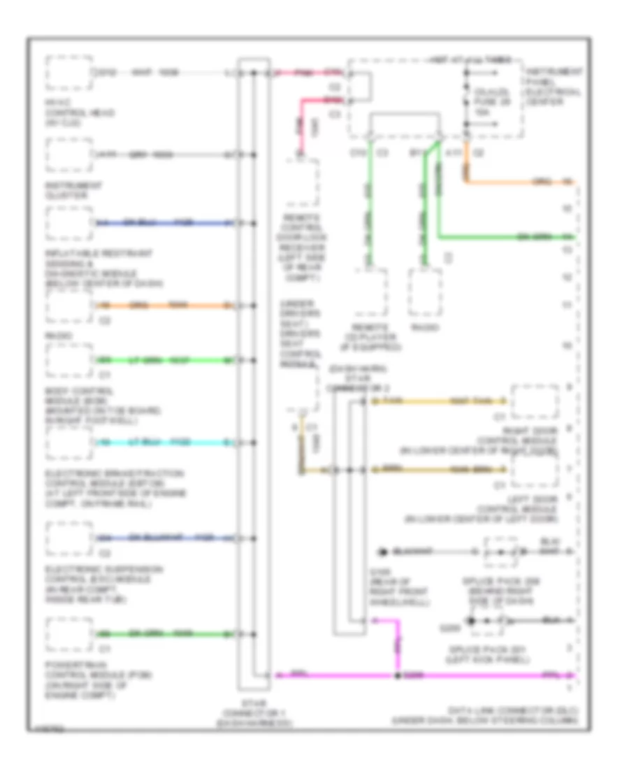
COMPUTER DATA LINES
Computer Data Lines for Chevrolet Corvette 1999
 https://portal-diagnostov.com/license.html
Automotive Electricians Portal FZCO
Automotive Electricians Portal FZCO
https://portal-diagnostov.com/license.html
https://portal-diagnostov.com/license.html
Automotive Electricians Portal FZCO
Automotive Electricians Portal FZCOList of elements for Computer Data Lines for Chevrolet Corvette 1999:
- (dash harn) star connector 2
- (under driver's seat) driver's seat control module
- A11
- B11
- Body control module (bcm) (mounted on toe board, in right footwell)
- C/laldl fuse 29 10a
- C10
- D12
- Data link connector (dlc) (under dash, below steering column)
- Electronic brake/traction control module (ebtcm) (at left frontside of engine compt, on frame rail)
- Electronic suspension control (esc) module (in rear compt, inside rear tub)
- G105 (rear of right front wheelwell)
- G200
- Hot at all times
- Hvac control head (w/ cj2)
- Inflatable restraint sensing & diagnostic module (below center of dash)
- Instrument cluster
- Instrument panel electrical center
- Left door control module (in lower center of left door)
- Pnk
- Powertrain control module (pcm) (on right side of engine compt)
- Radio
- Remote cd player (if equipped)
- Remote control door lock receiver (left side of rear compt)
- Right door control module (in lower center of right door)
- S206
- Splice pack 201 (left kick panel)
- Splice pack 208 (behind right side of dash)
- Star connector 1 (dash harness)
- Tan
- Tan d
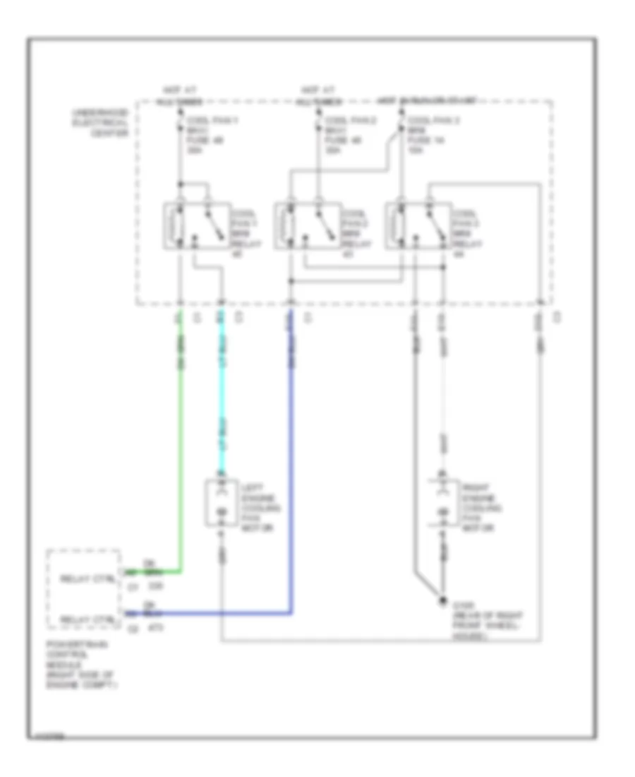
COOLING FAN
Cooling Fan Wiring Diagram for Chevrolet Corvette 1999
 https://portal-diagnostov.com/license.html
Automotive Electricians Portal FZCO
Automotive Electricians Portal FZCO
https://portal-diagnostov.com/license.html
https://portal-diagnostov.com/license.html
Automotive Electricians Portal FZCO
Automotive Electricians Portal FZCOList of elements for Cooling Fan Wiring Diagram for Chevrolet Corvette 1999:
- All times
- Cool fan 1 maxi fuse 49 30a
- Cool fan 1 mini relay
- Cool fan 2 maxi fuse 46 30a
- Cool fan 2 mini relay
- Cool fan 3 mini fuse 14 10a
- Cool fan 3 mini relay
- G105 (rear of right front wheel- house)
- Hot at
- Hot in run or start
- Left engine cooling fan motor
- Powertrain control module (right side of engine compt)
- Relay ctrl
- Right engine cooling fan motor
- Underhood electrical center
CRUISE CONTROL
Cruise Control Wiring Diagram for Chevrolet Corvette 1999
 https://portal-diagnostov.com/license.html
Automotive Electricians Portal FZCO
Automotive Electricians Portal FZCO
https://portal-diagnostov.com/license.html
https://portal-diagnostov.com/license.html
Automotive Electricians Portal FZCO
Automotive Electricians Portal FZCOList of elements for Cruise Control Wiring Diagram for Chevrolet Corvette 1999:
- Accelerator pedal position sensor (top of accelerator pedal)
- Act ctrl 1
- Act ctrl 2
- App 1 5v ref
- App 1 gnd
- App 1 sig
- App 2 5v ref
- App 2 gnd
- App 2 sig
- App 3 5v ref
- App 3 gnd
- App 3 sig
- Cr cont a
- Cruise control switch
- Exterior lights system
- Fuse 20 10a b
- Fuse 8 20a b
- G120 (right side of engine)
- Ground
- Headlamp & turn signal control switch
- Hot at all times
- Hot in run or start
- Hot with ign relay energized (in run or start)
- Ignition
- Instrument panel electrical center (in right front footwell)
- Nca
- Off
- On/off sig
- Pnk
- Powertrain control module (right side of engine compt)
- R/a
- Res/acc sig
- S120
- Set/coast sig
- Stop lamp switch (brake pedal support)
- Stop sw sig
- Stp haz a
- Tac serl data
- Tan
- Throt cont fuse 17 15a
- Throttle actuator control module (attached to pcm, below battery)
- Throttle actuator control motor (left side of throttle body)
- Throttle position sensor (on throttle body assembly)
- Tps 1 5v ref
- Tps 1 gnd
- Tps 1 sig
- Tps 2 5v ref
- Tps 2 gnd
- Tps 2 sig
- Underhood electrical center (right rear of engine compt)
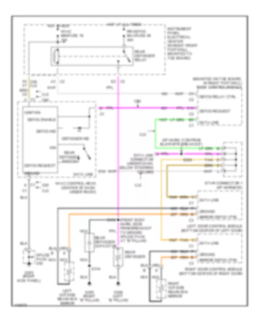
DEFOGGERS
Defogger Wiring Diagram for Chevrolet Corvette 1999
 https://portal-diagnostov.com/license.html
Automotive Electricians Portal FZCO
Automotive Electricians Portal FZCO
https://portal-diagnostov.com/license.html
https://portal-diagnostov.com/license.html
Automotive Electricians Portal FZCO
Automotive Electricians Portal FZCOList of elements for Defogger Wiring Diagram for Chevrolet Corvette 1999:
- (front body harn, 20cm from breakout to ground splice pack at "b" pillar)
- (i/p harn, 5 cm from blwr mtr breakout)
- (mounted on toe board, in right footwell) body control module
- C1 c
- C1 k
- C10
- C2 a5
- C60
- Cj2
- D12
- Data line
- Data link connector (under dash, below steering column)
- Defog enable
- Defog ind
- Defog relay ctrl
- Defog request
- Defogger ind
- E5 c3
- F6 c60 cj2 f7
- G203 (right kick panel)
- G305 (right "b" pillar)
- G308 (left "b" pillar)
- Ground
- Hot at all times
- Hot in run
- Hvac control head (center of dash, under radio)
- Hvac minifuse 18 10a
- Ign
- Ignition
- Instrument panel electrical center (in right front footwell, mounted to toe board)
- Left door control module (bottom center of left door)
- Left outside rearview mirror
- Mirror defog ctrl
- Nca
- Rear defogger
- Rear defogger capacitor
- Rear defogger relay
- Rear defogger switch
- Right door control module (bottom center of right door)
- Right outside rearview mirror
- Rr defog maxifuse 48 40a
- S206
- S312
- S314
- Splice pack
- Star connector 1 (i/p harness)
- Tan
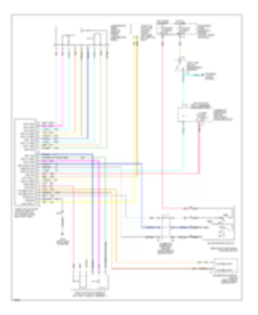
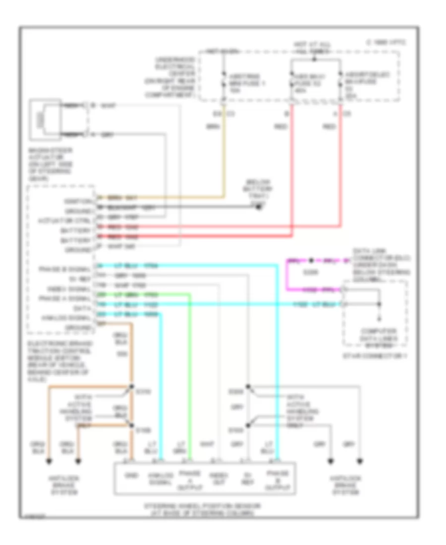
ELECTRONIC POWER STEERING
Electronic Power Steering Wiring Diagram for Chevrolet Corvette 1999
 https://portal-diagnostov.com/license.html
Automotive Electricians Portal FZCO
Automotive Electricians Portal FZCO
https://portal-diagnostov.com/license.html
https://portal-diagnostov.com/license.html
Automotive Electricians Portal FZCO
Automotive Electricians Portal FZCOList of elements for Electronic Power Steering Wiring Diagram for Chevrolet Corvette 1999:
- (below battery tray) g111
- 1995 vftc c
- 5v ref
- A c5
- Abs maxi fuse 52 40a
- Abs/rtdelec maxifuse 20a
- Abstrns mini fuse 1 10a
- Actuator ctrl
- Analog signal
- Antilock brake system
- Battery
- C3 e8
- Computer data lines system
- Data
- Data link connector (dlc) (under dash, below steering column)
- Electronic brake/ traction control module (ebtcm) (rear of vehicle, behind center of axle)
- Gnd
- Ground
- Hot at all all times
- Hot in on
- Ignition
- Index out
- Index signal
- Magnasteer actuator (on left side of steering gear)
- Nca
- Phase a output
- Phase a signal
- Phase b output
- Phase b signal
- Red
- S106
- S108
- S206
- S308
- S310
- Star connector 1
- Steering wheel position sensor (at base of steering column)
- Underhood electrical center (on right rear of engine compartment)
- With active handling system only
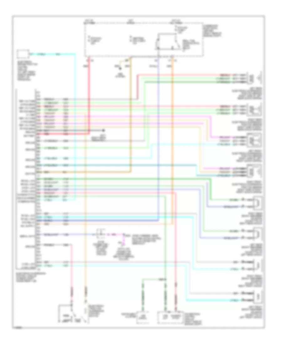
ELECTRONIC SUSPENSION
Electronic Suspension Wiring Diagram for Chevrolet Corvette 1999
 https://portal-diagnostov.com/license.html
Automotive Electricians Portal FZCO
Automotive Electricians Portal FZCO
https://portal-diagnostov.com/license.html
https://portal-diagnostov.com/license.html
Automotive Electricians Portal FZCO
Automotive Electricians Portal FZCOList of elements for Electronic Suspension Wiring Diagram for Chevrolet Corvette 1999:
- (dash harness, near blower motor control module connector breakout)
- 5 v ref
- A10
- A11
- A12
- A7 c3
- Abs system
- Abstrns mini fuse 5 10a
- B c5
- B10
- B11
- B12
- Battery
- C10
- C11
- C12
- C13
- Chassis pitch
- D10
- D11
- D12
- D13
- Data link connector (under dash, below steering column)
- Electronic brake/traction control module (at left front side of engine compt, on frame rail)
- Electronic suspension control module (in rear compt, inside rear tub)
- Electronic traction/ suspension control switch
- G417 (right rear frame rail)
- Ground
- Hot at all times
- Hot in run
- Ignition
- Instrument cluster
- Left front electronic suspension position sensor (right side of left front shock spring)
- Left front shock absorber solenoid (on bottom of left front shock)
- Left rear electronic suspension position sensor (right side of left rear shock spring)
- Left rear shock absorber solenoid (on bottom of left rear shock)
- Lf pos sens
- Lf sol high
- Lf sol low
- Lr pos sens
- Lr sol high
- Lr sol low
- Nca
- Orn
- Perf
- Powertrain control module (right side of engine compt)
- Real time damping (rtd) micro relay
- Red
- Ref voltage
- Rf pos sens
- Rf sol high
- Rf sol low
- Right front electronic suspension position sensor (right side of right front shock spring)
- Right front shock absorber solenoid (on bottom of right front shock)
- Right rear electronic suspension position sensor (right side of right rear shock spring)
- Right rear shock absorber solenoid (on bottom of right rear shock)
- Rr pos sens
- Rr sol high
- Rr sol low
- Rtd maxi fuse 51 20a
- Rtd mini fuse 7 10a
- Rtd relay
- S204
- S206
- Serial data
- Sport
- Star connector 1 (left side of body control module)
- State solid
- Steering pos
- Tour
- Underhood electrical center (right rear of engine compt)
- Vehicle speed
- Vss out
- Vss signal
ENGINE PERFORMANCE
5.7L
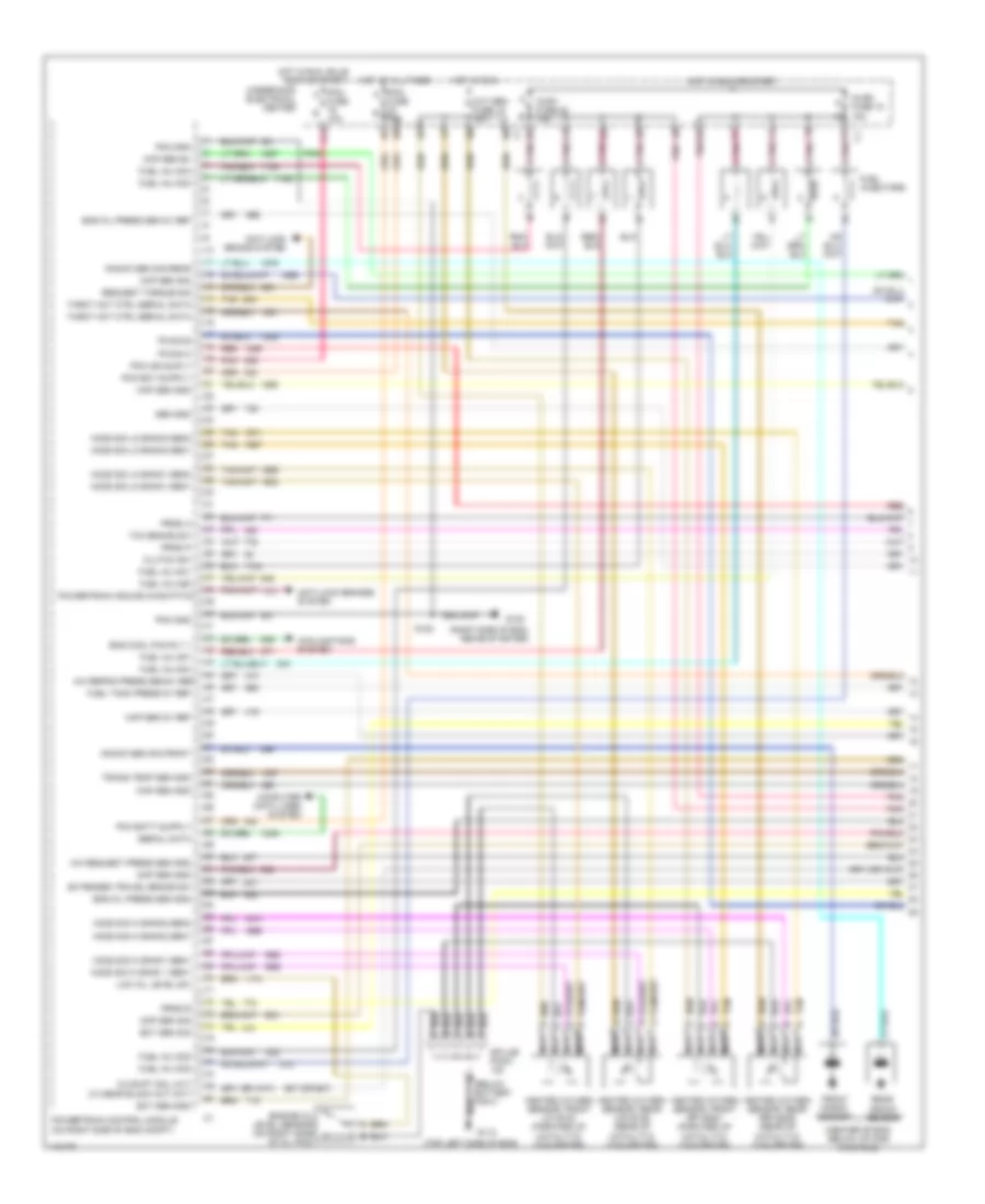
5.7L VIN G, Engine Performance Wiring Diagrams (1 of 4) for Chevrolet Corvette 1999
 https://portal-diagnostov.com/license.html
Automotive Electricians Portal FZCO
Automotive Electricians Portal FZCO
https://portal-diagnostov.com/license.html
https://portal-diagnostov.com/license.html
Automotive Electricians Portal FZCO
Automotive Electricians Portal FZCOList of elements for 5.7L VIN G, Engine Performance Wiring Diagrams (1 of 4) for Chevrolet Corvette 1999:
- (below battery tray)
- (center of eng, below intake manifold)
- (right side of eng, above starter)
- (top left side of eng)
- 10a
- 3-2 shift sol (a/t) 2-3 gear block out (m/t)
- 587 (or 687)
- A/c refrig press sen 5v ref
- A/c request press sen gnd
- Anti-lock brake system
- Anti-lock brakes system
- Ckp sen b+
- Ckp sen gnd
- Ckp sen sig
- Clutch sw
- Cmp sen gnd
- Cmp sen sig
- Computer data lines system
- Cooling fans system
- Ect sen gnd
- Ect sen sig
- Eng cool fan rly 1
- Eng oil press sen 5v ref
- Eng oil press sen gnd
- Engine oil level sensor (on right side of oil pan)
- Extended travel brake sw
- F11
- Front knock sensor
- Fuel inj n04
- Fuel inj n06
- Fuel inj n07
- Fuel inj no1
- Fuel inj no2
- Fuel inj no3
- Fuel inj no5
- Fuel inj no8
- Fuel injectors
- Fuel tank press 5v ref
- Fuse b
- G112
- G120
- Heated oxygen sensor, front (lf) b1s1 (forward of catalytic converter)
- Heated oxygen sensor, front (rf) b2s1 (forward of catalytic converter)
- Heated oxygen sensor, rear (lr) b1s2 (rear of catalytic converter)
- Heated oxygen sensor, rear (rr) b2s2 (rear of catalytic converter)
- Ho2s sig hi bank 1 sen1
- Ho2s sig hi bank1 sen1
- Ho2s sig hi bank2 sen1
- Ho2s sig hi bank2 sen2
- Ho2s sig lo bank1 sen1
- Ho2s sig lo bank1 sen2
- Ho2s sig lo bank2 sen1
- Ho2s sig lo bank2 sen2
- Hot at all times
- Hot in run
- Hot in run or start
- Hot in run, bulb test or start
- Injr1 fuse 22 15a
- Injr2 fuse 18 15a
- Knock sen sig front
- Knock sen sig rear
- Low oil level sw
- Map sen 5v ref
- Map sen gnd
- Nca
- Oxy sen fuse 15 15a
- Pcm a
- Pcm gnd
- Pcm ign suply
- Pnk
- Powertrain control module (on right side of eng compt)
- Powertrain induce chas pitch
- Prnd a
- Prnd b
- Prnd p
- Rear knock sensor
- Red
- Request torque sig
- Sen gnd
- Serial data
- Splice pack
- Tan
- Tcc brake sw
- Throt act ctrl serial data
- Tr sig b
- Tr sig c
- Trans temp sen gnd
- Underhood electrical center
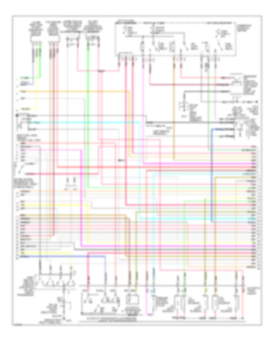
5.7L VIN G, Engine Performance Wiring Diagrams (2 of 4) for Chevrolet Corvette 1999
 https://portal-diagnostov.com/license.html
Automotive Electricians Portal FZCO
Automotive Electricians Portal FZCO
https://portal-diagnostov.com/license.html
https://portal-diagnostov.com/license.html
Automotive Electricians Portal FZCO
Automotive Electricians Portal FZCOList of elements for 5.7L VIN G, Engine Performance Wiring Diagrams (2 of 4) for Chevrolet Corvette 1999:
- (left rear of frame rail)
- (lower right side of eng) crankshaft position sensor
- (on left side of transmission) reverse inhibit solenoid
- (rear of right front wheelwell)
- (top center rear of eng) camshaft position sensor
- (under vehicle, on left side of transmission) 2-3 gear blockout solenoid
- 1-2 shift solenoid
- 10a
- 2-3 shift solenoid
- 3-2 shift solenoid
- A/t
- A12
- Air pmp fuse 50 20a
- Air pump relay
- Air sol relay
- Automatic trans- mission
- Automatic transmission fluid pressure manual valve position switch
- Automatic transmission fluid temp sensor
- B pnk (m/t)
- Cruise control release switch (on bracket, front of brake pedal)
- D10
- D2 sw
- D3 sw
- D4 sw
- E12
- Eng ign1 fuse 19
- F/pmp fuse 13 20a
- F12
- Fuel pump relay
- G101
- G103
- G112 (top left side of eng)
- G416
- Hot at all times
- Hot in run or start
- Hot with ign1 relay energized
- Left fuel level sensor (in left fuel tank)
- Lo sw
- M/t
- Nca
- Park/ neutral position & backup lamp switch (on left side of transmission)
- Pessure control solenoid valve
- Pnk
- Pnk (m/t)
- Pnk b
- Red
- Red a
- Rev sw
- Right fuel level sensor (in right fuel tank)
- S400
- S408
- S410
- Secondary air injection pump motor (left front of eng compt, on skid bar)
- Splice pack (near right headlamp assembly)
- Splice pack 122 (below battery tray)
- Splice pack 208 (right side of dash)
- Tan
- Tcc pwm solenoid
- Tcc solenoid
- Underhood elecrical center
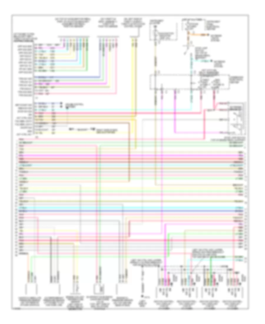
5.7L VIN G, Engine Performance Wiring Diagrams (3 of 4) for Chevrolet Corvette 1999
 https://portal-diagnostov.com/license.html
Automotive Electricians Portal FZCO
Automotive Electricians Portal FZCO
https://portal-diagnostov.com/license.html
https://portal-diagnostov.com/license.html
Automotive Electricians Portal FZCO
Automotive Electricians Portal FZCOList of elements for 5.7L VIN G, Engine Performance Wiring Diagrams (3 of 4) for Chevrolet Corvette 1999:
- (attached to pcm, below battery) throttle actuator control module
- (left ign ctrl mod jumper, approx 4 cm from breakout for ign ctrl/coil mod 5)
- (left ign ctrl mod jumper, approx 5cm from breakout for 8 pin in-line conn top center of valve cover)
- (left side of eng)
- (mil)
- (on left side of throttle body) throttle actuator control motor
- (on throttle body assembly) throttle position sensor
- (on top of accelerator pedal, part of mounting bracket) accelerator pedal position sensor
- (right side of eng, above starter)
- A/c refrigerant pressure sensor (attached to a/c high side line)
- Act ctrl no1
- Act ctrl no2
- App no1 5v
- App no1 sig
- App no2 5v
- App no2 gnd
- App no2 sig
- App no3 5v
- App no3 gnd
- App no3 sig
- B16
- Cruise control systsem
- Eng ign 1 a
- Engine coolant temperature sensor (left side of of eng, below generator)
- Engine oil pressure sensor (on top center rear of eng)
- Evaporative emission canister purge valve (top left side of eng, on intake manifold)
- Extended brake tra
- Exterior lights system
- Fuse 17 15a b
- Fuse 19 15a b
- Fuse 8 20a b
- G112
- G120
- Gnd
- Hot at all times
- Hot with ign relay energized (in run or start)
- Ign
- Ignition control/ coil module 1 (top of cylinder)
- Ignition control/ coil module 3 (top of cylinder)
- Ignition control/ coil module 5 (top of cylinder)
- Ignition control/ coil module 7 (top of cylinder)
- Instrument cluster
- Instrument panel electrical center
- Malfunction indicator lamp
- Manifold absolute pressure sensor (on top rear of intake manifold)
- On/off sig
- Plug spark
- Pnk
- Pnk b
- Pnk d
- Pnk d ign ctrl
- Pp no1 gnd
- Red c ign ctrl
- Ref lo
- Res/acc sig
- S101
- S103
- S105
- S120
- S213
- Set/coast sig
- Spark plug
- Stop lamp switch (on top of brake pedal support) c2
- Stop lamp switch (top of brake pedal support)
- Stop sw sig
- Stp haz a
- Tac serl data
- Tan
- Throt cont a
- Tps no1 5v
- Tps no1 sig
- Tps no2 5v
- Tps no2 gnd
- Tps no2 sig
- Underhood electrical center
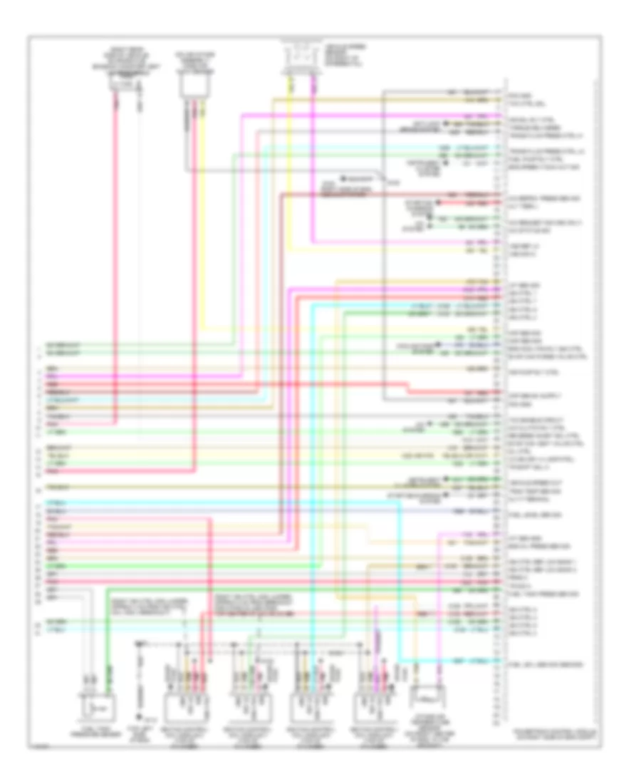
5.7L VIN G, Engine Performance Wiring Diagrams (4 of 4) for Chevrolet Corvette 1999
 https://portal-diagnostov.com/license.html
Automotive Electricians Portal FZCO
Automotive Electricians Portal FZCO
https://portal-diagnostov.com/license.html
https://portal-diagnostov.com/license.html
Automotive Electricians Portal FZCO
Automotive Electricians Portal FZCOList of elements for 5.7L VIN G, Engine Performance Wiring Diagrams (4 of 4) for Chevrolet Corvette 1999:
- (on air intake assembly) mass air flow sensor
- (right ign ctrl mod jumper, approx 4 cm from ign ctrl/ coil mod 4 breakout)
- (right ign ctrl mod jumper, approx 5 cm from breakout for 8 pins in-line conn top center of valve cover)
- (right rear side of vehicle) evaporative emission canister vent valve solenoid
- (right side of eng, above starter)
- (top left side of eng)
- 1223 (or 375)
- 2-3 ss (or 1-4 lamp ctrl)
- A gnd
- A pnk
- A/c clutch rly ctrl
- A/c refrig press sen sig
- A/c request sig (c60 only)
- A/c status sig
- A/c system
- Air pump rly ctrl
- Air sol rly ctrl
- Alt f terminal
- Alt term l
- Anti-lock brake system
- B ref lo
- C pnk
- Cooling fans system
- D ign
- Eng cool fan rly 2&3 ctrl
- Eng oil press sen sig
- Eng speed (tach) out sig
- Evap can purge valve ctrl
- Evap can vent valve ctrl
- Fuel level sen sig
- Fuel levl sen sig (second)
- Fuel pump rly ctrl
- Fuel tank press sen sig
- Fuel tank pressure sensor
- G112
- G120
- Iat sen gnd
- Iat sen sig
- Ign ctrl 1
- Ign ctrl 2
- Ign ctrl 3
- Ign ctrl 4
- Ign ctrl 5
- Ign ctrl 6
- Ign ctrl 7
- Ign ctrl 8
- Ign ctrl ref low bank 1
- Ign ctrl ref low bank 2
- Ignition control/ coil module 2 (top of cylinder)
- Ignition control/ coil module 4 (top of cylinder)
- Ignition control/ coil module 6 (top of cylinder)
- Ignition control/ coil module 8 (top of cylinder)
- Instrument cluster system
- Intake air temperature sensor (on front center of eng, in the air duct)
- Maf sen sig
- Map sen sig
- Mil ctrl
- Pcm gnd
- Plug
- Plug spark
- Pnk
- Powertrain control module (on right side of eng compt)
- Prnd c
- Red
- Red c ign ctrl
- Reverse inhibit sol ctrl
- S100
- S102
- S104
- S120
- Spark
- Starting/ charging system
- Starting/charging system
- Tan
- Tcc ctrl sol
- Tcc enable circuit
- Torque delivered
- Tr shift sol a
- Tr sig a
- Tran temp sen sig
- Trans fluid press ctrl hi
- Trans fluid press ctrl lo
- Vehicle speed out
- Vehicle speed sensor (on right of differential)
- Vss ref lo
- Vss sig hi
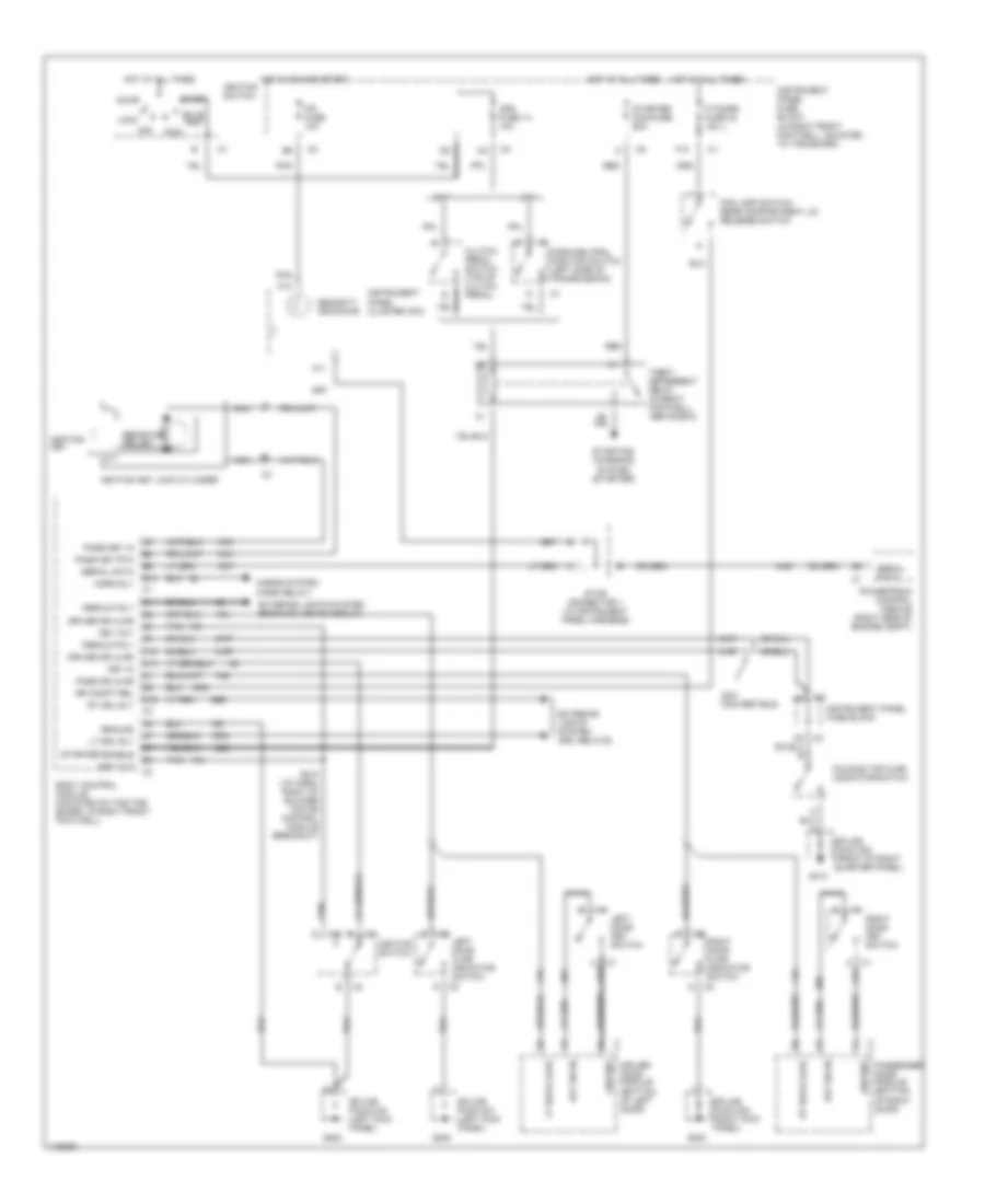
EXTERIOR LIGHTS
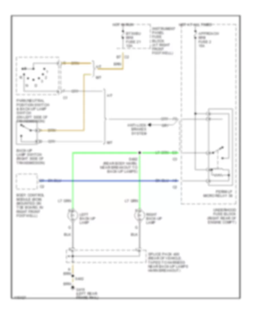
Back-up Lamps Wiring Diagram for Chevrolet Corvette 1999
 https://portal-diagnostov.com/license.html
Automotive Electricians Portal FZCO
Automotive Electricians Portal FZCO
https://portal-diagnostov.com/license.html
https://portal-diagnostov.com/license.html
Automotive Electricians Portal FZCO
Automotive Electricians Portal FZCOList of elements for Back-up Lamps Wiring Diagram for Chevrolet Corvette 1999:
- A/t
- Anti-lock brakes system
- Approach mini fuse 2 15a
- Back-up lamp switch (right side of transmission)
- Body control module (bcm) (mounted on toe board, in right front footwell)
- Btsi/bu mini fuse 21 10a
- C2 b7
- G416 (left rear frame rail)
- Hot at all times
- Hot in run
- Instrument panel fuse block (at right front footwell)
- Left back-up lamp
- M/t
- Park/neutral position switch & back-up lamp switch (on left side of transmission)
- Perim lp micro relay 38
- Right back-up lamp
- S402
- S482 (rear body harn, near breakout to back-up lamps)
- Splice pack 400 (rear of vehicle, taped to harness near back-up lamps harn breakout)
- Underhood fuse block (right rear of engine compt)
Exterior Lamps Wiring Diagram for Chevrolet Corvette 1999
 https://portal-diagnostov.com/license.html
Automotive Electricians Portal FZCO
Automotive Electricians Portal FZCO
https://portal-diagnostov.com/license.html
https://portal-diagnostov.com/license.html
Automotive Electricians Portal FZCO
Automotive Electricians Portal FZCOList of elements for Exterior Lamps Wiring Diagram for Chevrolet Corvette 1999:
- (left rear frame rail) g416
- A15
- A16
- Alc prk lp relay
- Alc relay
- Anti-lock brakes system
- Approach mini fuse 2 15a
- B10
- B12
- Body control module (bcm) (mounted on toe board, in right footwell)
- C12
- Center high mount stop lamp (chmsl)
- D11
- D12
- D16
- Drl left relay
- Drl right relay
- E12
- F12
- Flasher
- G105
- G200
- Hazard sw
- Hazard warning switch
- Hazt/sg mini fuse 15 20a
- Head
- Headlamp switch
- Hot at all times
- Hot in run or start
- Instrument cluster
- Instrument panel fuse block
- Interior lights system
- Left front park/ turn lamp
- Left front side marker b lamp
- Left rear side marker lamp
- Left tail/ stop/ turn lamps
- Lft drl ctrl
- Lft turn in
- License lamps
- Nca
- Nca b
- Off
- Park
- Pk/tlp mini fuse 6 10a
- Pnk
- R nca
- Right front park/ turn lamp
- Right front side marker lamp
- Right rear side marker lamp
- Right tail/ stop/ turn lamps
- Rt drl ctrl
- Rt turn in
- S205 (dash harness, 4cm right of radio module)
- S481 (rear body harn, near breakout to left tail/stop/ turn lamps)
- S484 (rear body harn, near breakout to back-up lamps)
- S492 (rear body harn, near breakout to right tail/stop/ turn lmps)
- Splice pack 100 (rear of right front wheelwell)
- Splice pack 102 (under right headlamp, taped to harness)
- Splice pack 201 (at left kick panel)
- Splice pack 400 (rear of vehicle, taped to harness near back-up lamps)
- Stoplamp switch
- Stp/haz mini fuse 8 20a
- Turn signal switch
- Underhood fuse block
- Z nca
GROUND DISTRIBUTION
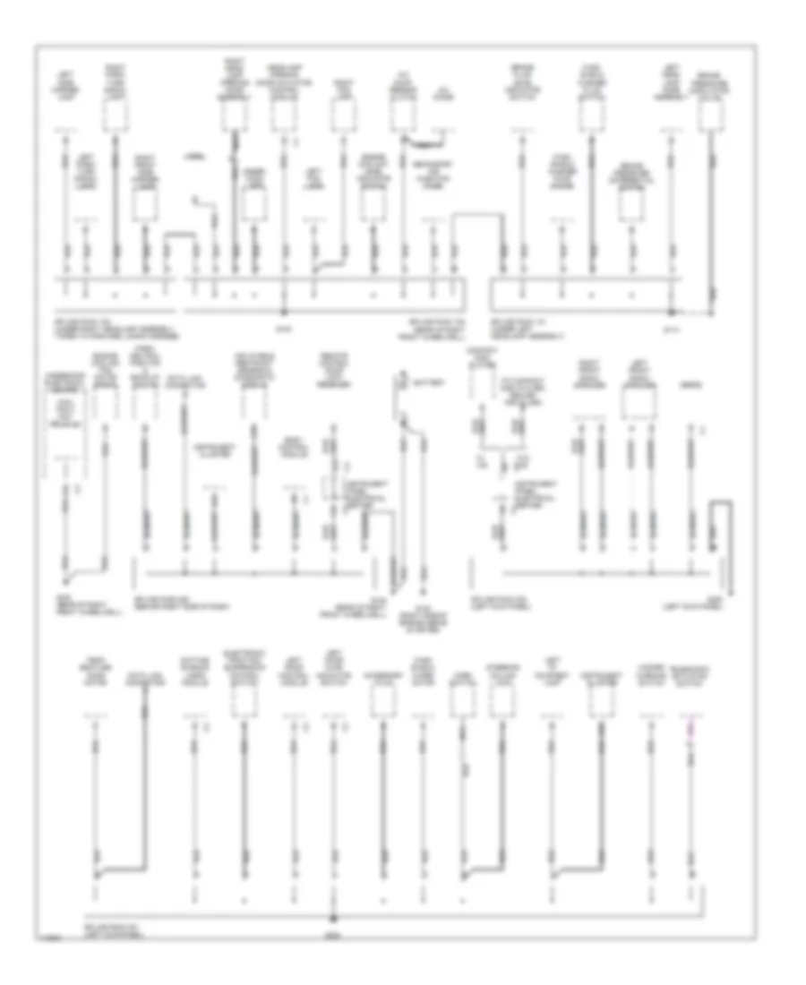
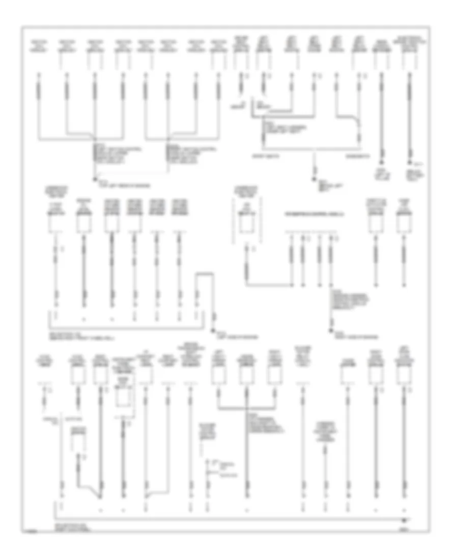
Ground Distribution Wiring Diagram (1 of 3) for Chevrolet Corvette 1999
 https://portal-diagnostov.com/license.html
Automotive Electricians Portal FZCO
Automotive Electricians Portal FZCO
https://portal-diagnostov.com/license.html
https://portal-diagnostov.com/license.html
Automotive Electricians Portal FZCO
Automotive Electricians Portal FZCOList of elements for Ground Distribution Wiring Diagram (1 of 3) for Chevrolet Corvette 1999:
- (to compact disc player, dealer installed)
- A/c comp- ressor clutch
- A/c diode
- A12
- A18
- Accessory plug
- B13
- B15
- Battery
- Body control module
- Brake fluid level indicator switch
- Brake pressure differential switch
- Brake pressure modulator valve
- Compact disc player
- Cool fan 3 mini- relay 44
- Data link connector
- Daytime running lamps module
- Electronic traction/ suspension control switch
- Engine coolant level indicator switch
- Engine cooling fan motor (right)
- F11
- F12
- G105
- G105 (rear of right front wheelwell)
- G113
- G120 (right side of engine above starter)
- G200
- G200 (left kick panel)
- Hazard warning switch
- Headlamp opening door actuator control module
- Horn
- Horn switch
- Inflatable restraint sensing & diagnostic module
- Instrument cluster
- Instrument panel electrical center
- Left door ajar indicator switch
- Left door control module
- Left fog lamp
- Left front radio speaker
- Left head- lamp door assembly
- Left i/p courtesy lamp
- Left park/ turn signal lamp
- Left side marker lamp
- Nca
- Park/ neutral position & back-up switch
- Radio
- Remote control door lock receiver
- Right fog lamp
- Right front radio speaker
- Right front side marker lamp
- Right head- lamp opening door assembly
- Right park/ turn signal lamp
- Secondary air injection pump
- Splice pack 100 (rear of right front wheelwell)
- Splice pack 101 (under left headlamp assembly)
- Splice pack 102 (under right headlamp assembly, taped to forward lamps harness)
- Splice pack 201 (left kick panel)
- Splice pack 203 (left kick panel)
- Splice pack 208 (behind right side of dash)
- Steering column lock
- Telescopic actuator switch
- Temp- erature door motor
- Under- hood lamp
- Underhood electrical center
- W/ uis
- W/o uis
- Wind- shield washer fluid switch
- Wind- shield washer pump motor
- Wind- shield wiper motor
Ground Distribution Wiring Diagram (2 of 3) for Chevrolet Corvette 1999
 https://portal-diagnostov.com/license.html
Automotive Electricians Portal FZCO
Automotive Electricians Portal FZCO
https://portal-diagnostov.com/license.html
https://portal-diagnostov.com/license.html
Automotive Electricians Portal FZCO
Automotive Electricians Portal FZCOList of elements for Ground Distribution Wiring Diagram (2 of 3) for Chevrolet Corvette 1999:
- (below battery tray)
- (left "b" pillar)
- Auto a/c
- Base seats
- Blower motor control module
- Blower motor relay (manual a/c)
- Body control module
- Bose mini- relay 43
- Brake/ transmission shift interlock control solenoid
- Cigar lighter
- D10
- Driver seat control module
- Electronic brake traction control module
- Engine oil level sensor
- F/ pmp micro- relay 35
- F12
- G111
- G112 (left side of engine)
- G114 (top left rear of engine)
- G120 (right side of engine)
- G203
- G308
- G312 (behind left seat)
- Heated oxygen sensor (lf) b1s1
- Heated oxygen sensor (lr) b1s2
- Heated oxygen sensor (rf) b2s1
- Heated oxygen sensor (rr) b2s2
- Hvac control head
- I/p compart- ment lamp
- Ign mini- relay 42
- Ignition coil module 1
- Ignition coil module 2
- Ignition coil module 3
- Ignition coil module 4
- Ignition coil module 5
- Ignition coil module 6
- Ignition coil module 7
- Ignition coil module 8
- Ignition switch
- Inside rearview mirror
- Instrument panel electrical center
- Left door ajar indicator switch
- Left seat belt switch
- Left seat relay center
- Left seat upper motor
- Left vanity mirror lamp
- Manual a/c
- Mass air flow sensor
- Nca
- Powertrain control module
- Rear window defogger
- Right courtesy lamp
- Right door control module
- Right vanity mirror lamp
- S100 (right ignition control module jumper, near ignition coil module 8)
- S101 (left ignition control module jumper, near ignition coil module 1)
- S120 (engine harness, near powertrain control module breakout)
- S202 (i/p harness, 39cm right of inside rearview mirror breakout)
- S301 (left seat harness, under left seat)
- Splice pack 122 (behind right front wheelwell)
- Splice pack 202 (right kick panel)
- Sport seats
- Throttle actuator control module
- Underhood electrical center
- W/ memory
- W/o memory
- Wire end taped to instrument panel harness
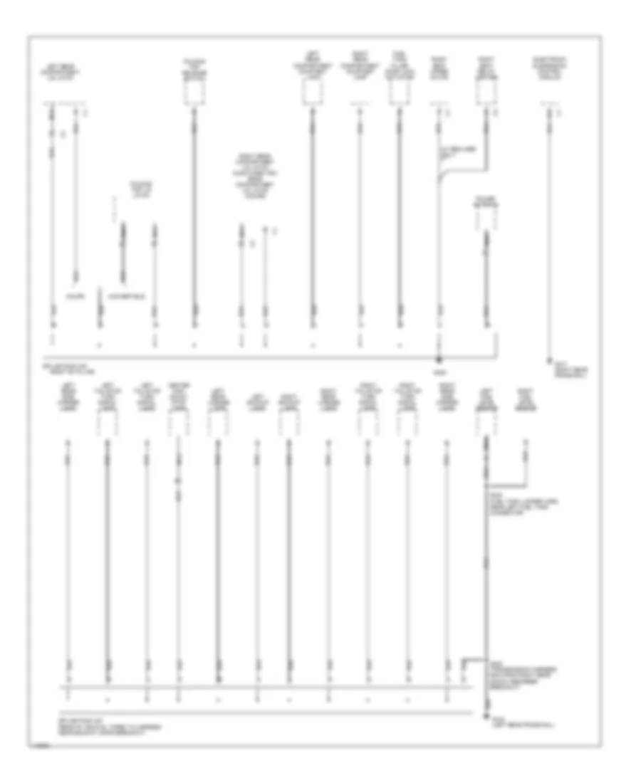
Ground Distribution Wiring Diagram (3 of 3) for Chevrolet Corvette 1999
 https://portal-diagnostov.com/license.html
Automotive Electricians Portal FZCO
Automotive Electricians Portal FZCO
https://portal-diagnostov.com/license.html
https://portal-diagnostov.com/license.html
Automotive Electricians Portal FZCO
Automotive Electricians Portal FZCOList of elements for Ground Distribution Wiring Diagram (3 of 3) for Chevrolet Corvette 1999:
- (right "b" pillar)
- (w/ recliner only)
- A12
- Center high mount stop lamp
- Convertible
- Coupe
- Electronic suspension control module
- Folding top lid latch
- Folding top release switch
- Fuel tank filler door lock actuator
- G305
- G416 (left rear frame rail)
- G417 (right rear frame rail)
- Left backup lamp
- Left fuel level sensor
- Left rear compartment courtesy lamp
- Left rear compartment lid latch
- Left rear license lamp
- Left rear side marker lamp
- Left tail/stop turn signal lamp
- Nca
- Power antenna
- Right backup lamp
- Right fuel level sensor
- Right rear compartment courtesy lamp
- Right rear compartment lid latch (conv/hard top) rear compartment lid latch (coupe)
- Right rear license lamp
- Right rear side marker lamp
- Right seat relay center
- Right seat upper motor
- Right tail/stop turn signal lamp
- S402 (transmission harness, 55cm from right rear shock absorber breakout)
- S408 (fuel tank jumper harn, near left fuel tank connector)
- Splice pack 302
- Splice pack 400 (rear of vehicle, taped to harness near backup lamps breakout)
HEADLIGHTS
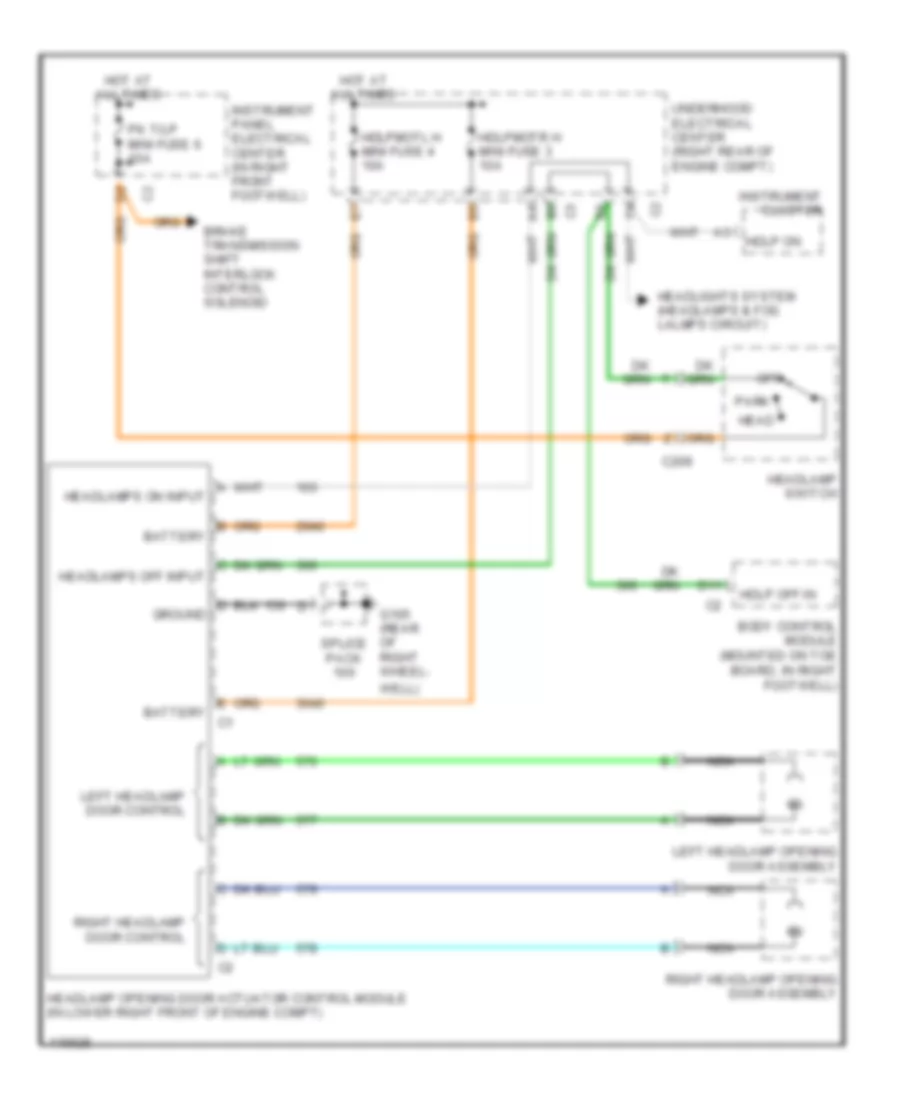
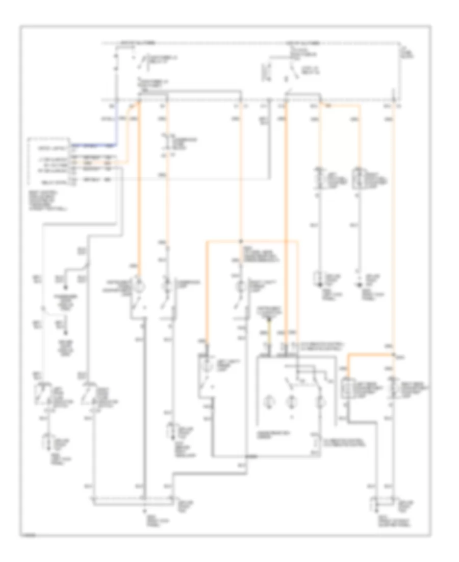
Headlamp Doors Wiring Diagram for Chevrolet Corvette 1999
 https://portal-diagnostov.com/license.html
Automotive Electricians Portal FZCO
Automotive Electricians Portal FZCO
https://portal-diagnostov.com/license.html
https://portal-diagnostov.com/license.html
Automotive Electricians Portal FZCO
Automotive Electricians Portal FZCOList of elements for Headlamp Doors Wiring Diagram for Chevrolet Corvette 1999:
- A headlamps on input
- B battery
- B6 c3
- Body control module (mounted on toe board, in right footwell)
- Brake transmission shift interlock control solenoid
- C209
- D ground
- D11
- E battery c1
- G105 (rear of right wheel-
- Hdlp off in
- Hdlp on
- Hdlpmotl h mini fuse 4 10a
- Hdlpmotr h mini fuse 3 10a
- Head
- Headlamp opening door actuator control module (in lower right front of engine compt)
- Headlamp switch
- Headlamps off input
- Headlights system (headlamps & fog lalmps circuit)
- Hot at all times
- Instrument cluster
- Instrument panel electrical center (in right front footwell)
- Left headlamp door control
- Left headlamp opening door assembly
- Nca
- Off
- Park
- Pk t/lp mini fuse 6 10a
- Right headlamp door control
- Right headlamp opening door assembly
- Splice pack
- Underhood electrical center (right rear of engine compt)
- Well)
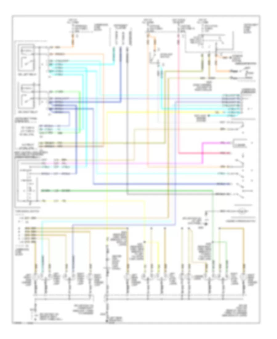
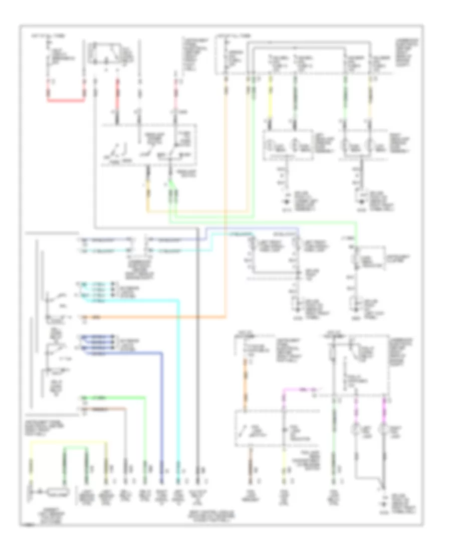
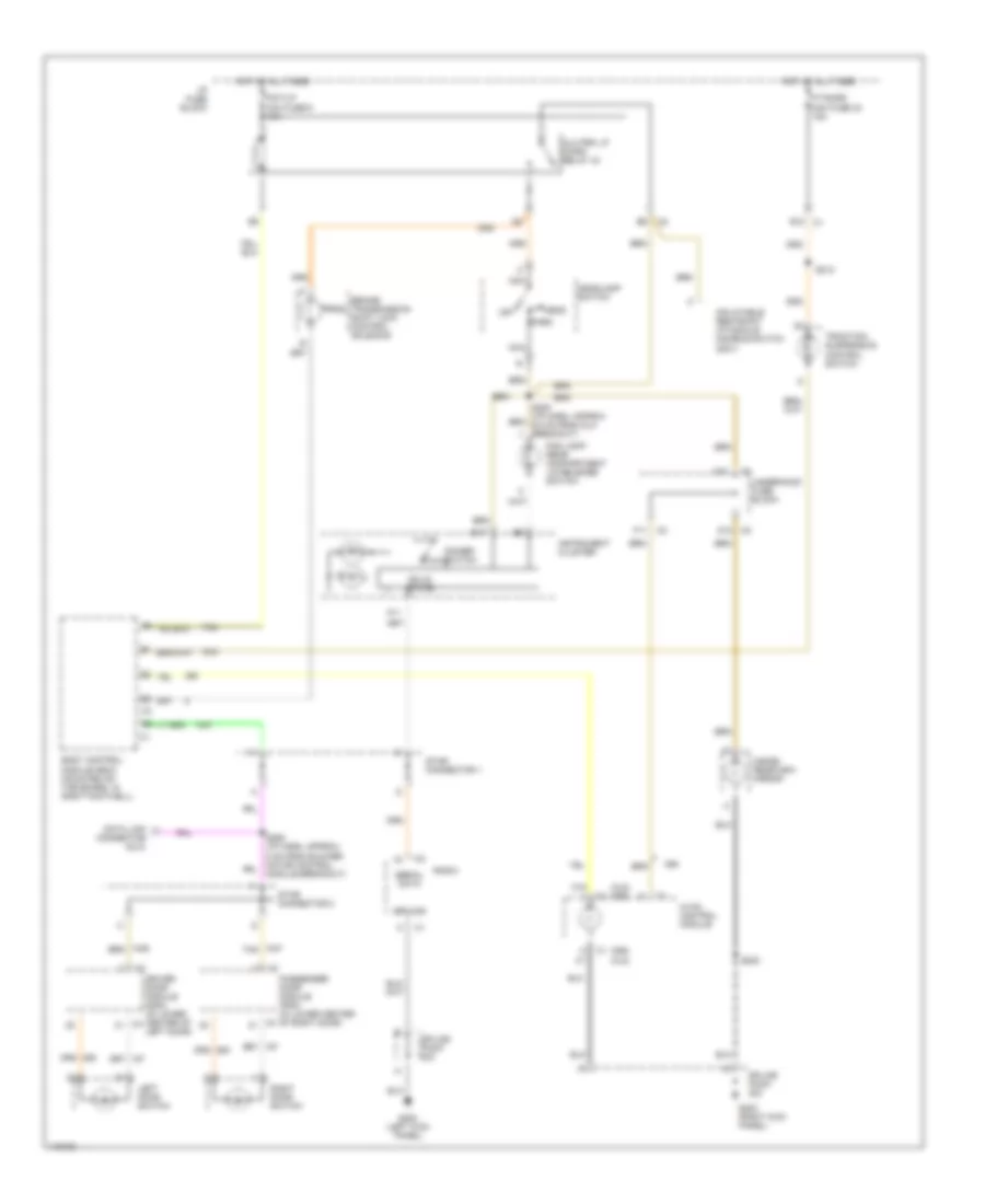
Headlamps & Fog Lamps Wiring Diagram for Chevrolet Corvette 1999
 https://portal-diagnostov.com/license.html
Automotive Electricians Portal FZCO
Automotive Electricians Portal FZCO
https://portal-diagnostov.com/license.html
https://portal-diagnostov.com/license.html
Automotive Electricians Portal FZCO
Automotive Electricians Portal FZCOList of elements for Headlamps & Fog Lamps Wiring Diagram for Chevrolet Corvette 1999:
- A c4
- A10
- Alc hclp relay ctrl
- Alc hdlp micro relay
- Ambient light sensor (top of dic switches)
- Amplifier
- Aproch mini fuse 2 15a
- B10
- B15
- Body control module (mounted on toe board, in right footwell)
- C10
- C209
- C4 c3
- D10 c2
- D16
- Drl l micro relay
- Drl l relay ctrl
- Drl r micro relay
- Drl r relay ctrl
- E1 c2
- E4 c3
- Exterior lights system
- F/tnk dr minifuse 32 15a
- F12 c1
- F4 c2
- Flash
- Flash -to- pass switch
- Fog lamp ind ctrl
- Fog lamp on indicator
- Fog lamp relay ctrl
- Fog lamp request
- Fog lamp switch
- Fog lamp/ rear compartment lid release switch
- Fog lp micro- relay
- Fog lp minifuse 6 10a
- G105
- G113
- G200
- Hdhibml mini fuse 12 10a
- Hdhibmr mini fuse 9 10a
- Hdlobml mini fuse 10 10a
- Hdlobmr mini fuse 8 10a
- Hdlp circuit breaker 54 20a
- Head
- Headlamp dimmer switch
- Headlamp switch
- High
- High beam
- High beam indicator
- Hot at all times
- Instrument cluster
- Instrument panel electrical center (right front foot- well)
- Instrument panel electrical center (right front footwell)
- Left fog lamp
- Left front turn signal/ park lamp
- Left headlamp opening door assembly
- Left turn signal in
- Light sensor ground ctrl
- Light sensor input ctrl
- Low
- Low beam
- Nca
- Off
- Park
- Red
- Right fog lamp
- Right headlamp opening door assembly
- Right turn signal in
- Splice pack
- Splice pack (left kick panel)
- Splice pack 100 (rear of right front wheel)
- Splice pack 100 (rear of right front wheelwell)
- Splice pack 101 (under left headlamp assembly)
- Tan
- Underhood electrical center (right rear of engine compt)
HORN
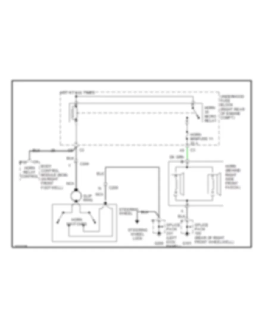
Horn Wiring Diagram for Chevrolet Corvette 1999
 https://portal-diagnostov.com/license.html
Automotive Electricians Portal FZCO
Automotive Electricians Portal FZCO
https://portal-diagnostov.com/license.html
https://portal-diagnostov.com/license.html
Automotive Electricians Portal FZCO
Automotive Electricians Portal FZCOList of elements for Horn Wiring Diagram for Chevrolet Corvette 1999:
- B10
- Body control module (bcm) (in right front footwell)
- C209
- G101
- G200
- Horn (behind right side front fascia)
- Horn micro relay
- Horn minifuse 11 20 a
- Horn relay control
- Horn switches
- Hot at all times
- Nca
- Slip ring
- Splice pack (left kick panel)
- Splice pack (rear of right front wheelwell)
- Steering wheel
- Steering wheel lock
- Underhood fuse block (right rear of engine compt)
INSTRUMENT CLUSTER
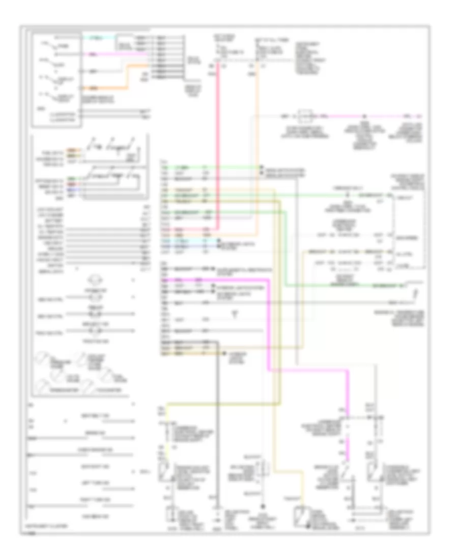
Instrument Cluster Wiring Diagram for Chevrolet Corvette 1999
 https://portal-diagnostov.com/license.html
Automotive Electricians Portal FZCO
Automotive Electricians Portal FZCO
https://portal-diagnostov.com/license.html
https://portal-diagnostov.com/license.html
Automotive Electricians Portal FZCO
Automotive Electricians Portal FZCOList of elements for Instrument Cluster Wiring Diagram for Chevrolet Corvette 1999:
- (1999-2000 only)
- (on right rear of engine compt)
- (on right side of engine compt) powertrain control module
- 1-4 ind
- A10
- A11
- A12
- A13
- A14
- A15
- A16
- A17
- Abs ind
- Abs ind ctrl
- Air bag ind
- B10
- B11
- B12
- B13
- B14
- B15
- B16
- B17
- Battery
- Bcm 1 & ipc mini fuse 25 10a
- Brake fluid level switch (in master cylinder reservoir)
- Brake ind
- C10
- Check engine ind
- Coolant temper- ature gauge
- Data link connector (under dash, below steering column)
- Dim
- Dimmer/head-up display switch
- Display down
- Display up
- E/m
- E/m sw in
- Eng speed
- Engine coolant level indicator switch (on bottom of coolant reservoir)
- Engine data
- Engine oil temperature gauge sensor (on bottom left rear of engine)
- Exterior lights system
- F10
- Fuel
- Fuel gauge
- Fuel sw in
- G105
- G105 (rear of right front wheelwell)
- G113
- G200
- Gauges
- Gauges sw in
- Gnd
- Ground
- Haz sw input
- Head-up display (hud)
- Headlights system
- High beam ind
- Hot at all times
- Hot in run or start
- Ign
- Ignition
- Illumination
- Instrument cluster
- Instrument panel electrical center (in right front footwell, mounted to toe board)
- Inter lt dimm
- Interior lights system
- Ipc mini fuse 19 10a
- Left turn ind
- Low coolant
- Low washer
- M/t
- Mil ctrl
- Nca
- Oil pressure gauge
- Oil temp rtn
- Oil temp sig
- Option
- Options sw in
- Page
- Park brake switch (on parking brake lever)
- Pnk
- Red
- Reset
- Reset sw in
- Right turn ind
- S204 (dash harn, 7.5 cm from fbec connector)
- S206 (dash harn, 14cm from blower motor control module connector breakout)
- Seat belt ind
- Sec ind ctrl
- Security ind
- Serial data
- Skip shift ind
- Solid state
- Speedometer
- Splice pack 100 (rear of right front wheelwell)
- Splice pack sp101 (under left headlamp assembly)
- Splice pack sp201 (left kick panel)
- Splice pack sp208 (behind right side of dash)
- Star connector 1 (dash harn, serial data link sub-harness)
- Tachometer
- Trac ind ctrl
- Traction ind
- Trip sw in
- Trip/ odo
- Underhood electrical center
- Underhood electrical center (on right rear of engine compt)
- Volts gauge
- Vss input
- Vss out
- Windshield washer solvent level switch (inside solvent container)
INTERIOR LIGHTS
Courtesy Lamps Wiring Diagram for Chevrolet Corvette 1999
 https://portal-diagnostov.com/license.html
Automotive Electricians Portal FZCO
Automotive Electricians Portal FZCO
https://portal-diagnostov.com/license.html
https://portal-diagnostov.com/license.html
Automotive Electricians Portal FZCO
Automotive Electricians Portal FZCOList of elements for Courtesy Lamps Wiring Diagram for Chevrolet Corvette 1999:
- (w/ remote control (w/o remote control
- (w/ remote control)
- (w/o remote control)
- A12
- B+ voltage
- B12
- Body control module (bcm) (mounted on toe board, in right footwell)
- C c2
- C/laldl mini fuse 29 10a
- C11
- C12
- C2 a
- C2 b
- Crtsy lmp rly
- Ctsy lp relay 42
- D c2
- Driver door module (ddm)
- F3 c2
- G107 (behind right headlamp)
- G200 (left kick panel)
- G203 (right kick panel)
- G413 (front of right quarter panel)
- Hot at all times
- I/p fuse block
- Inside rearview mirror
- Instrument illumination circuit
- Instrument panel compartment lamp
- Left door ajar indicator switch
- Left footwell courtesy lamp
- Left rear compartment courtesy lamp
- Left vanity mirror lamp
- Lt dr ajar sw
- Monitored ld mini fuse 2 10a
- Monitored ld relay 37
- Nca
- Passenger door module (pdm)
- Relay cntrl
- Right door ajar indicator switch
- Right footwell courtesy lamp
- Right rear compartment courtesy lamp
- Right vanity mirror lamp
- Rt dr ajar sw
- S200 (i/p harn, near inside rearview mirror breakout)
- S202
- S303
- Splice pack
- Underhood fuse block
- Underhood lamp
Instrument Illumination Wiring Diagram for Chevrolet Corvette 1999
 https://portal-diagnostov.com/license.html
Automotive Electricians Portal FZCO
Automotive Electricians Portal FZCO
https://portal-diagnostov.com/license.html
https://portal-diagnostov.com/license.html
Automotive Electricians Portal FZCO
Automotive Electricians Portal FZCOList of elements for Instrument Illumination Wiring Diagram for Chevrolet Corvette 1999:
- (c60) (cj2)
- (cj2) (c60)
- A11
- Alc prk lp micro relay 43
- B17
- Body control module (bcm) (mounted on toe board, in right footwell)
- Brake/ transmission shift lock control solenoid
- C16 j
- C2 f11
- C60
- D11
- D12 c2
- Data link connector (dlc)
- Dimmer switch
- Driver door module (ddm) (in lower center of left door)
- E12 c1
- F/tnkdr mini fuse 32 15a
- Fog lamp/ rear compartment lid release switch
- G200 (left kick panel)
- G203 (right kick panel)
- Ground
- Head
- Headlamp switch
- Hot at all times
- Hvac control module
- I/p fuse block
- Inflatable restraint i/p module disable switch (2001)
- Inside rearview mirror
- Instrument cluster
- K c1
- Left door switch
- Nca
- Off
- Park
- Passenger door module (pdm) (in lower center of right door)
- Pk/tlp mini fuse 6 10a
- Prndl
- Radio
- Right door switch
- S202
- S206 (i/p harn, approx 5 cm from blower motor control module breakout)
- S212
- Serial data
- Solid state
- Splice pack
- Star connector 1
- Star connector 2
- Tan
- Traction/ suspension control switch
- Underhood fuse block
MEMORY SYSTEMS
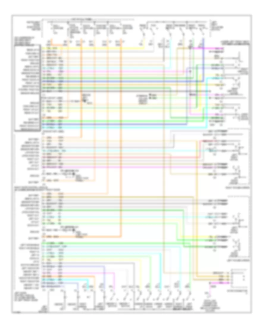
Memory Seat & Mirrors Wiring Diagram for Chevrolet Corvette 1999
 https://portal-diagnostov.com/license.html
Automotive Electricians Portal FZCO
Automotive Electricians Portal FZCO
https://portal-diagnostov.com/license.html
https://portal-diagnostov.com/license.html
Automotive Electricians Portal FZCO
Automotive Electricians Portal FZCOList of elements for Memory Seat & Mirrors Wiring Diagram for Chevrolet Corvette 1999:
- (behind left seat)
- (on underside of driver's seat) driver's seat control module
- (pins a-b not used)
- (pins e-f not used)
- (under left front seat) left seat lower motor
- B11
- B9 c2
- Battery
- C1 b12
- C11 c1
- C12 c1
- Data link connector (under dash, below steering column)
- Dcm l minifuse 10a
- Dcm r minifuse 10a
- Down in
- Down out
- Forward in
- Forward out
- Front down
- Front down in
- Front down out
- Front position
- Front up
- Front up in
- Front up out
- Front vertical motor
- Fwd
- Fwd/rev position
- G200 (left kick panel)
- G203 (right kick panel)
- G312
- Ground
- Horiz- ontal motor
- Hot at all times
- Indicator power
- Instrument panel electrical center
- L/r position
- Left door control module (in lower center of left front door)
- Left door switch
- Left in
- Left indicator
- Left mir enable
- Left miror select
- Left mirror ind
- Left out
- Left power mirror
- Left seat adjuster switch
- Left/ right motor
- Memory 1 ind
- Memory 1 switch
- Memory 2 ind
- Memory 2 switch
- Memory ind
- Memory set 1
- Memory set 2
- Mirror down
- Mirror left
- Mirror right
- Mirror up
- Nca
- Pwr fdl minifuse 25a
- Pwr fdr minifuse 25a
- Pwr st/dvr circuit breaker 20a
- Rear down
- Rear down in
- Rear down out
- Rear position
- Rear up
- Rear up in
- Rear up out
- Rear vertical motor
- Reverse
- Reverse in
- Reverse out
- Right door control module (in lower center of right front door)
- Right in
- Right indicator
- Right mir enable
- Right mirror ind
- Right mirror select
- Right out
- Right power mirror
- S206
- S391
- S392
- Scm l minifuse 10a
- Sensor ground
- Sensor power
- Sensor return
- Serial data
- Splice pack 201
- Splice pack 202
- Star connector
- Steering column memory circuit
- Switch ground
- Tan
- Up in
- Up out
- Up/ down motor
- Up/dn position
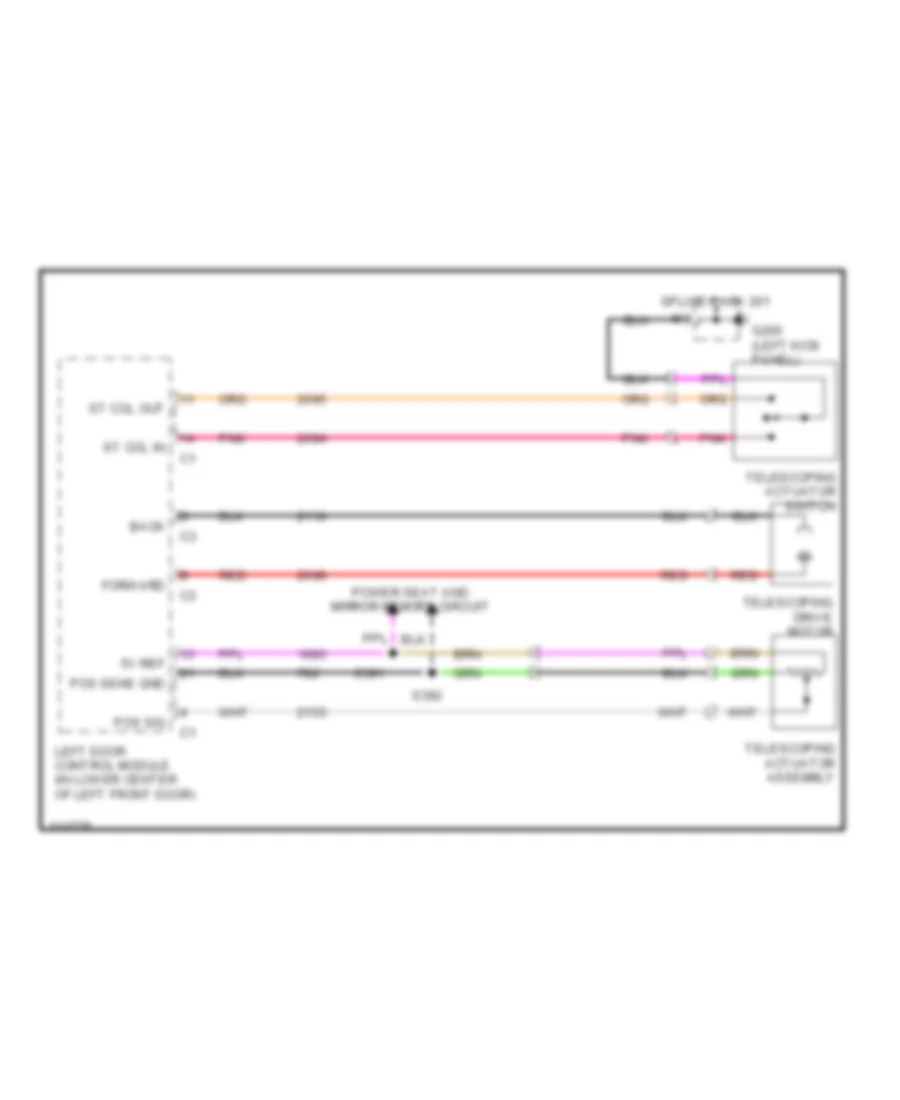
Steering Column Memory Wiring Diagram for Chevrolet Corvette 1999
 https://portal-diagnostov.com/license.html
Automotive Electricians Portal FZCO
Automotive Electricians Portal FZCO
https://portal-diagnostov.com/license.html
https://portal-diagnostov.com/license.html
Automotive Electricians Portal FZCO
Automotive Electricians Portal FZCOList of elements for Steering Column Memory Wiring Diagram for Chevrolet Corvette 1999:
- 5v ref
- Back
- Forward
- G200 (left kick panel)
- Left door control module (in lower center of left front door)
- Pnk
- Pos sens gnd
- Pos sig
- Power seat and mirror memory circuit
- Red
- S391
- S392
- Splice pack 201
- St col in
- St col out
- Telescoping actuator assembly
- Telescoping actuator switch
- Telescoping drive motor
POWER ANTENNA
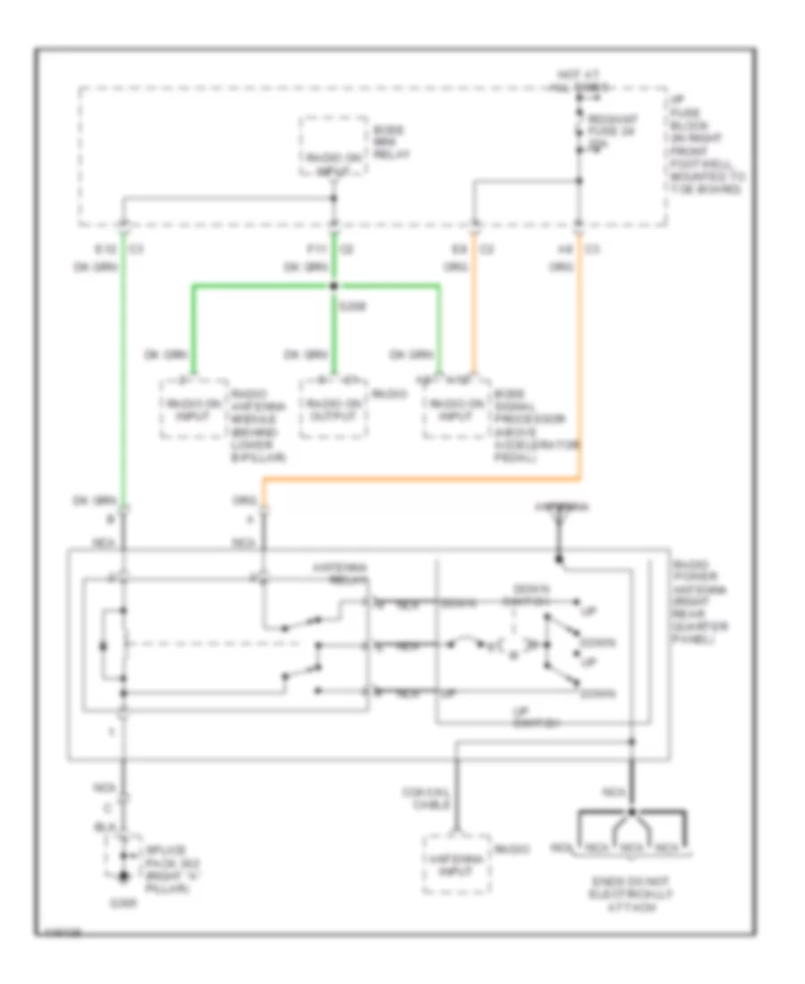
Power Antenna Wiring Diagram for Chevrolet Corvette 1999
 https://portal-diagnostov.com/license.html
Automotive Electricians Portal FZCO
Automotive Electricians Portal FZCO
https://portal-diagnostov.com/license.html
https://portal-diagnostov.com/license.html
Automotive Electricians Portal FZCO
Automotive Electricians Portal FZCOList of elements for Power Antenna Wiring Diagram for Chevrolet Corvette 1999:
- A12
- A8 c3
- Antenna
- Antenna input
- Antenna relay
- Bose mini relay
- Bose signal processor (above accelerator pedal)
- C2 e8
- C2 f11
- Coaxial cable
- Down
- Down switch
- E12 c3
- Ends do not electrically attach
- G305
- Hot at all times
- I/p fuse block (in right front footwell, mounted to toe board)
- Nca
- Radio
- Radio antenna module (behind lower b-pillar)
- Radio on input
- Radio on output
- Radio power antenna (right rear quarter panel)
- Rdo/ant fuse 24 20a
- S208
- Splice pack 302 (right "a" pillar)
- Up switch
POWER DISTRIBUTION
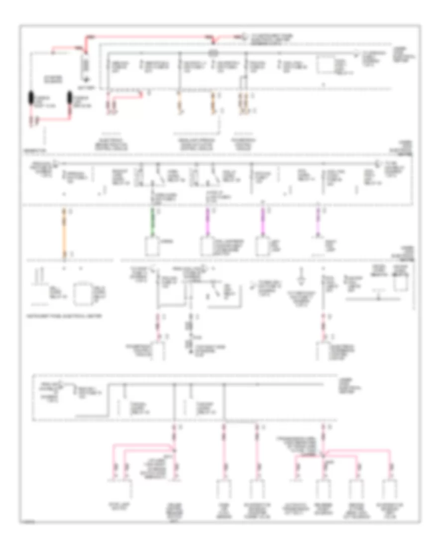
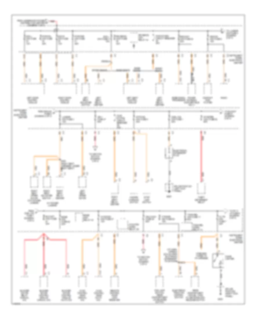
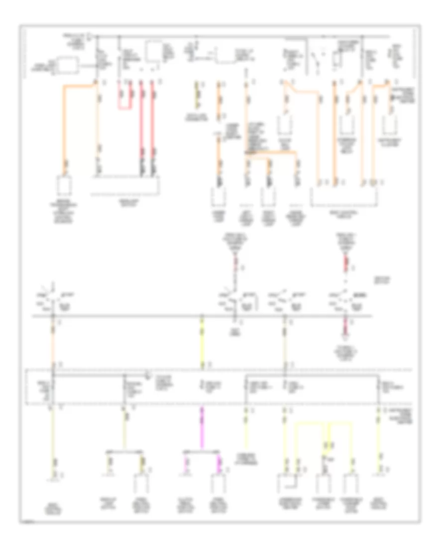
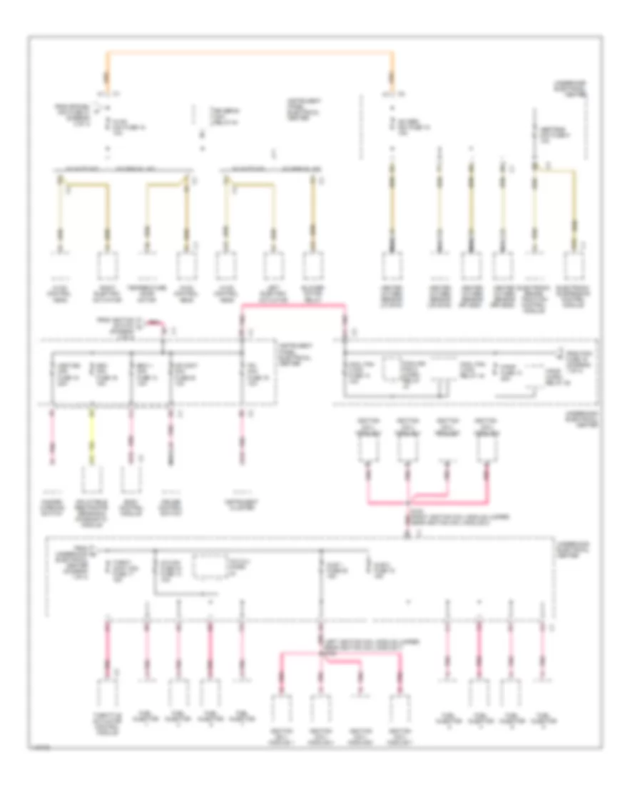
Power Distribution Wiring Diagram (1 of 4) for Chevrolet Corvette 1999
 https://portal-diagnostov.com/license.html
Automotive Electricians Portal FZCO
Automotive Electricians Portal FZCO
https://portal-diagnostov.com/license.html
https://portal-diagnostov.com/license.html
Automotive Electricians Portal FZCO
Automotive Electricians Portal FZCOList of elements for Power Distribution Wiring Diagram (1 of 4) for Chevrolet Corvette 1999:
- (a/t only)
- (diagram 1 of 4)
- (i/p harn, 7.5cm right of brake switch conn breakout)
- (top right side of engine) g120
- (transmission harn, 6.5cm rearward of trans harn to fuel tank jumper)
- Abs maxi fuse 52 40a
- Abs rtd elc maxi fuse 53 20a
- Air pmp maxi use 50 20a
- Air pmp micro- relay 33
- Air sol micro- relay 40
- Aproach mini fuse 2 15a
- Automatic transmission
- Backup lmps micro- relay 38
- Battery
- C1 electronic suspension control motor
- Cool fan 1 maxi fuse 49 30a
- Cool fan 1 mini- relay 41
- Cool fan 2 maxi fuse 46 30a
- Cool fan 2 mini- relay 43
- Cruise control release switch (m/t)
- Drl l micro- relay 40
- Drl r micro- relay
- Electronic brake/traction control module
- Eng ign 1 mini fuse 19 10a
- Evaporative emission canister purge valve
- Evaporative emission vent valve
- F11
- Fog lamp/rear compartment lid release switch
- Fog lp micro- relay 39
- Fog lp mini fuse 6 10a
- From cool b fan fuse 49 (diagram 1 of 4)
- From cool fan c 2 fuse 46 (diagram 1 of 4)
- From ign d mini-relay
- Fusible link gra 20 ga
- Fusible link rust 10 ga
- Generator
- Hdlpmotl h mini fuse 4 10a
- Hdlpmotr h mini fuse 3 10a
- Headlamp opening door actuator control module
- Horn micro mini fuse 2 20a
- Horn micro- relay 36
- Horns
- Ign mini- relay
- Instrument panel electrical center
- Left fog lamp
- Mass air flow sensor
- Pcm mini fuse 16 10a
- Pcm mini fuse 23 10a
- Pnk
- Powertrain control module
- Red
- Reverse inhibit solenoid
- Right fog lamp
- Rtd maxi use 51 20a
- Rtd micro- relay 41
- Rtd mini fuse 7 10a
- S120
- S213
- S400
- Second & third gear lock- out solenoid
- Starter solenoid
- Stop lamp switch
- To aproach fuse 2 (diagram 1 of 4)
- To egn ign 1 mini fuse 19 (diagram 1 of 4)
- To f/pmp fuse 13 (diagram 4 of 4)
- To ign mini-relay (diagram 1 of 4)
- To instrument panel electrical center (diagram 2 of 4)
- To throtcont mini fuse 17 (diagram 4 of 4)
- Under- hood electrical center
Power Distribution Wiring Diagram (2 of 4) for Chevrolet Corvette 1999
 https://portal-diagnostov.com/license.html
Automotive Electricians Portal FZCO
Automotive Electricians Portal FZCO
https://portal-diagnostov.com/license.html
https://portal-diagnostov.com/license.html
Automotive Electricians Portal FZCO
Automotive Electricians Portal FZCOList of elements for Power Distribution Wiring Diagram (2 of 4) for Chevrolet Corvette 1999:
- (i/p harn, approx 22.5 cm from elctronic accessory plug conn)
- (w/ power lumbar)
- A12
- B11
- B12
- Base seats
- Blo mot maxi fuse 30a
- Blower motor control module (auto a/c)
- Blower motor control module (manual a/c)
- Blower motor relay (manual a/c)
- Bose mini fuse 28 20a
- Bose mini- relay 43
- Bose signal processor
- C/ltr mini fuse 7 25a
- C11
- C12
- Cigar lighter
- Cnsl cig mini fuse 1 20a
- Compact disc player
- Dcm l mini fuse 10a
- Dcm r mini fuse 10a
- E12
- Electronic accessory plug
- Electronic traction control switch
- F/tnkdr mini fuse 50 15a
- F12
- Fog lamp switch/ rear compartment lid release switch
- From g cnsl cig fuse 1 (diagram 2 of 4)
- From rdo/cd e fuse 5 (diagram 2 of 4)
- From underhood power distribution center (diagram 1 of 4)
- G200
- G203
- Hazard warning switch
- Htchtrk micro- relay 39
- Hvac control head (auto a/c)
- Hvac control head (manual a/c)
- Hvaccon mini fuse 27 10a
- Ign 1 fuse 47 60a
- Ign 2 maxi fuse 45 60a
- Instrument panel electrical center
- Left door control module
- Left seat adjuster switch
- Left seat control module
- Left seat relay center
- Left seat upper motor
- Lumbar mini fuse 3 15a
- Nca
- Power antenna (convertible only)
- Pwr fdl mini fuse 25a
- Pwr fdr mini fuse 25a
- Pwr st/drv circuit breaker 20a
- Pwr st/pas circuit breaker 20a
- Radio
- Rdo/ant mini fuse 24 20a
- Rdo/cd mini fuse 5 15a
- Rear compartment lid/fuel tank filler doorlock release switch
- Red
- Remote control door lock receiver
- Right door control module
- Right seat adjuster switch
- Right seat relay center
- Right seat upper motor (w/o power lumbar)
- Rr defog maxi fuse 40a
- Rr defog mini- relay 44
- S212
- S300 (right seat harness, under right seat)
- Scm l mini fuse 4 10a
- Splice pack 201 (left kick panel)
- Splice pack 202 (right kick panel)
- Sport seats
- Starter maxi fuse 52 60a
- Stop lamp switch
- Stp/haz mini fuse 8 20a
- Theft deterrent relay
- To blomot fuse 51 (diagram 2 of 4)
- To ignition switch (diagram 3 of 4)
- To lumbar mini fuse 3 (diagram 2 of 4)
- To pk t/ lp fuse 6 (diagram 3 of 4)
- Tonn rel micro- relay 41
- Tonn rel mini fuse 17 10a
- Wire end taped to i/p harness
Power Distribution Wiring Diagram (3 of 4) for Chevrolet Corvette 1999
 https://portal-diagnostov.com/license.html
Automotive Electricians Portal FZCO
Automotive Electricians Portal FZCO
https://portal-diagnostov.com/license.html
https://portal-diagnostov.com/license.html
Automotive Electricians Portal FZCO
Automotive Electricians Portal FZCOList of elements for Power Distribution Wiring Diagram (3 of 4) for Chevrolet Corvette 1999:
- (i/p harn, 22.5cm right of inside rearview mirror breakout) s200
- (not used)
- A/t
- A11
- A12
- A14
- Acc
- Alc hdlp micro relay
- Alc park lamp micro relay
- Asry off mini fuse 11 20a
- B11
- Back-up lamp switch
- Bcm 2 mini fuse 10a
- Bcm a mini fuse 9 10a
- Bcm/ ipc mini fuse 10a
- Bcmi 3 mini fuse 10a
- Body control module
- Brake/ transmission shift interlock control solenoid
- Btsi/bu mini fuse 21 10a
- Bulb test
- C/l aldl fuse 10a
- Clutch pedal position switch
- Crk mini fuse 14 10a
- Ctsy lp micro- relay 42
- D12
- Data link connector
- From c/ltr fuse 7 (diagram 2 of 4)
- From ign 1 fuse 47 (diagram 2 of 4)
- From ign 2 maxi fuse 45 (diagram 2 of 4)
- Glove box lamp
- Hdlp circuit breaker 20a
- Headlamp switch
- Ignition switch
- Inside rearview mirror lamp
- Instrument cluster
- Instrument panel electrical center
- Left vanity mirror lamp
- M/t
- Monit- ored ld mini fuse 2 10a
- Monitored ld micro relay 37
- Nca
- Off
- Park/ neutral position switch
- Pk t/lp mini fuse 6 10a
- Pnk
- Red
- Right vanity mirror lamp
- Run
- Start
- Steering column lock relay
- To bcmi 1 mini fuse 13 (diagram 4 of 4)
- To hvac fuse 18 (diagram 4 of 4)
- Under -hood elect center
- Under- hood lamp
- Underhood electrical center
- Windshield washer pump motor
- Windshield wiper switch
- Wire end taped to i/p harness
- Wsw fuse 10 25a
Power Distribution Wiring Diagram (4 of 4) for Chevrolet Corvette 1999
 https://portal-diagnostov.com/license.html
Automotive Electricians Portal FZCO
Automotive Electricians Portal FZCO
https://portal-diagnostov.com/license.html
https://portal-diagnostov.com/license.html
Automotive Electricians Portal FZCO
Automotive Electricians Portal FZCOList of elements for Power Distribution Wiring Diagram (4 of 4) for Chevrolet Corvette 1999:
- (diagram 3 of 4)
- (left ignition coil module jumper, near ignition coil module 7) s103
- A/c clu micro
- A/c mini fuse 24 fuse 14 10a
- A13
- Abstrns mini fuse 5 10a
- B12
- Bcmi 1 mini fuse 13 10a
- Blower motor relay
- Body control module
- Cool fan 3 mini fuse 14 10a
- Cool fan 3 mini relay 44
- Cooling fan 2 micro- relay
- Cr cont mini fuse 20 10a
- Cruise control switch
- D13
- Electrical center (diagram 1 of 4)
- Electronic brake/ traction control module
- Electronic suspension control module
- F/pmp fuse 13 20a
- F/pmp micro- relay 35
- From btsi/bu mini fuse 21 (diagram 3 of 4)
- From ignition switch l
- From pcm fuse 16 (diagram 1 of 4)
- From underhood m
- Fuel injector
- Hazard warning switch
- Heated oxygen sensor (lf) b1s1
- Heated oxygen sensor (lr) b1s2
- Heated oxygen sensor (rf) b2s1
- Heated oxygen sensor (rr) b2s2
- Hvac control head
- Hvac mini fuse 18 10a
- Hzdt/sg mini fuse 15 20a
- Ignition coil/ module 1
- Ignition coil/ module 2
- Ignition coil/ module 3
- Ignition coil/ module 4
- Ignition coil/ module 5
- Ignition coil/ module 6
- Ignition coil/ module 7
- Ignition coil/ module 8
- Inflatable restraints sensing & diagnostic module
- Injr 1 fuse 22 15a
- Injr 2 fuse 18 15a
- Instrument cluster
- Instrument panel electrical center
- Ipc mini fuse 19 10a
- Left electric actuator
- Nca
- Oxygen mini fuse 15 15a
- Pnk
- Pnk a
- Pnk a11
- Pnk d5
- Right electric actuator
- Rr defog mini- relay 44
- S102 (right ignition coil module jumper, near ignition coil module 2)
- Sdm mini fuse 16 15a
- Temperature door motor
- Throt- cont mini fuse 17 15a
- Throttle actuator control module
- Underhood electrical center
- W/ auto a/c
- W/ manual a/c
POWER DOOR LOCKS
Power Door Lock Wiring Diagram for Chevrolet Corvette 1999
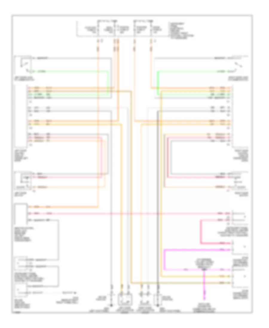 https://portal-diagnostov.com/license.html
Automotive Electricians Portal FZCO
Automotive Electricians Portal FZCO
https://portal-diagnostov.com/license.html
https://portal-diagnostov.com/license.html
Automotive Electricians Portal FZCO
Automotive Electricians Portal FZCOList of elements for Power Door Lock Wiring Diagram for Chevrolet Corvette 1999:
- (i/p harness, 7 cm left of bcm connector c2 breakout) s208
- A12
- B11
- B12
- C10
- C11
- C12
- D12
- Data link connector (under dash, below steering column)
- Dcm/l fuse 33 10a
- Dcm/r fuse 30 10a
- F12
- G103 (rear of right front wheelwell)
- G200 (left kick panel)
- G203 (right kick panel)
- Hot at all times
- Hvac con fuse 27 10a
- Instrument panel electrical center (in right front footwell, mounted to toe board)
- Left door control module (inside left door)
- Left door lock actuator motor
- Left door lock cylinder switch
- Left door switch
- Lock
- Pnk
- Pwr fdl fuse 34 25a
- Pwr fdr fuse 31 25a
- Remote control door lock receiver (on left side of rear compartment)
- Right door control module (inside right door)
- Right door lock actuator motor
- Right door lock cylinder switch
- Right door switch
- Splice pack 201
- Splice pack 202
- Splice pack 208 (behind right side of dash)
- Star connector 1 (i/p harness, serial data)
- Star connector 2 (i/p harness, serial data)
- Tan
- Unlock
POWER SEATS
6-Way Power Seat Wiring Diagram for Chevrolet Corvette 1999
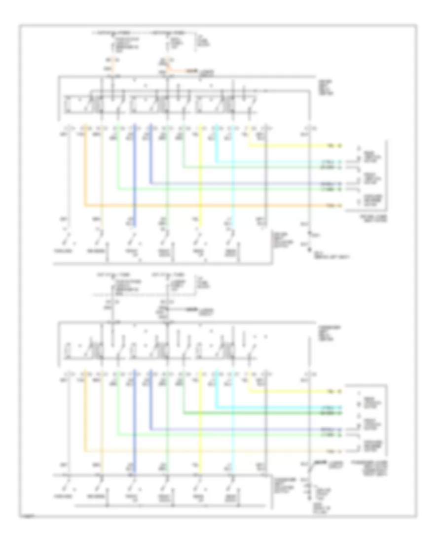 https://portal-diagnostov.com/license.html
Automotive Electricians Portal FZCO
Automotive Electricians Portal FZCO
https://portal-diagnostov.com/license.html
https://portal-diagnostov.com/license.html
Automotive Electricians Portal FZCO
Automotive Electricians Portal FZCOList of elements for 6-Way Power Seat Wiring Diagram for Chevrolet Corvette 1999:
- B c3
- B2 c3
- B9 c2
- C c2
- C c3
- C2 c
- C2 d
- C2 e
- C2 f
- C3 b
- C3 c
- C3 d
- C3 d2
- D c2
- D c3
- Driver lower seat motor
- Driver seat adjuster switch
- Driver seat relay center
- E c2
- F c2
- Forward
- Forward/ reverse motor
- Front down
- Front up
- Front up/down motor
- Front vertical motor
- G305 (right "b" pillar)
- G312 (behind left seat)
- Hot at all times
- I/p fuse block
- Lumbar circuit
- Lumbar fuse 3 10a
- Passenger lower seat motor (under right front seat)
- Passenger seat adjuster switch
- Passenger seat relay center
- Pwr st/dvr circuit breaker 35 20a
- Pwr st/pass circuit breaker 36 20a
- Rear down
- Rear up
- Rear up/down motor
- Rear vertical motor
- Reverse
- S300
- S301
- Scm-l fuse 4 10a
- Splice pack
- Tan
Lumbar Wiring Diagram for Chevrolet Corvette 1999
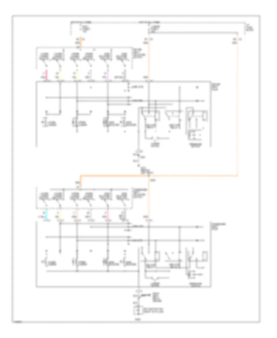 https://portal-diagnostov.com/license.html
Automotive Electricians Portal FZCO
Automotive Electricians Portal FZCO
https://portal-diagnostov.com/license.html
https://portal-diagnostov.com/license.html
Automotive Electricians Portal FZCO
Automotive Electricians Portal FZCOList of elements for Lumbar Wiring Diagram for Chevrolet Corvette 1999:
- A c2
- B1 c2
- C c1
- C1 a
- C1 h
- C1 k
- C2 c
- C2 d
- C2 e
- C2 e3
- C2 f
- C2 g
- C3 b2
- D c1
- Deflate
- Deflate relay
- Driver seat adjuster switch
- Driver seat pump
- F c1
- G c1
- G301
- G305
- G312 (behind left seat)
- H c2
- Hot at all times
- I/p fuse block
- Inflate
- Inflate relay
- K c2
- Lower lumbar
- Lower lumbar deflate
- Lower lumbar inflate
- Lumbar fuse 3 15a
- Lumbar motor
- Passenger seat adjuster switch
- Passenger seat pump
- Pnk
- Pressure switch
- Right seat relay center
- S300
- Scm l fuse 4 10a
- Side bolster
- Side bolster deflate
- Side bolster inflate
- Splice pack 302 (right "b" pillar)
- Upper lumbar
- Upper lumbar deflate
- Upper lumbar inflate
POWER WINDOWS
Power Window Wiring Diagram for Chevrolet Corvette 1999
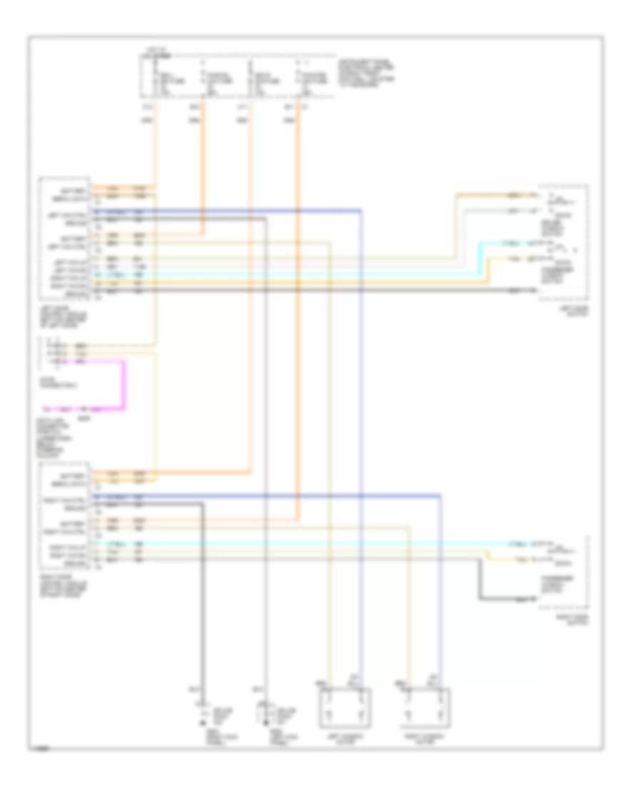 https://portal-diagnostov.com/license.html
Automotive Electricians Portal FZCO
Automotive Electricians Portal FZCO
https://portal-diagnostov.com/license.html
https://portal-diagnostov.com/license.html
Automotive Electricians Portal FZCO
Automotive Electricians Portal FZCOList of elements for Power Window Wiring Diagram for Chevrolet Corvette 1999:
- B11
- B12
- Battery
- C11
- C12
- Data link connector (partial) (under dash, below steering column)
- Dcm l mini fuse 10a
- Dcm r mini fuse 10a
- Down
- Driver window switch
- G200 (left kick panel)
- G203 (right kick panel)
- Ground
- Hot at all times
- Instrument panel electrical center (in right front footwell, mounted to toe board)
- Left door control module (bottom center of left door)
- Left door switch
- Left win ctrl
- Left win dn
- Left win up
- Left window motor
- Passenger window switch
- Pwr fdl mini fuse 25a
- Pwr fdr mini fuse 25a
- Right door control module (bottom center of right door)
- Right door switch
- Right win ctrl
- Right win dn
- Right win up
- Right window motor
- S206
- Serial data
- Splice pack
- Star connector 2
- Tan
RADIO
Radio Wiring Diagrams, with Bose System for Chevrolet Corvette 1999
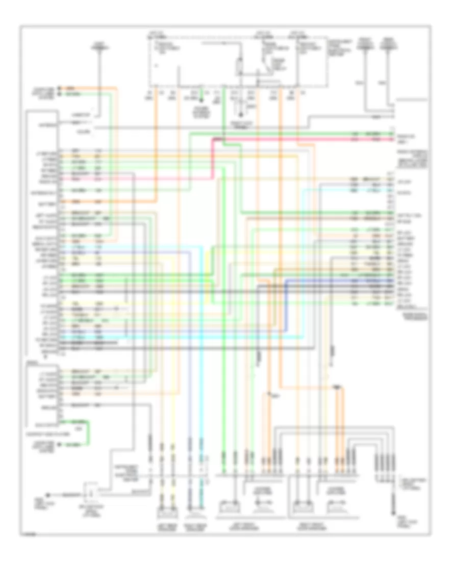 https://portal-diagnostov.com/license.html
Automotive Electricians Portal FZCO
Automotive Electricians Portal FZCO
https://portal-diagnostov.com/license.html
https://portal-diagnostov.com/license.html
Automotive Electricians Portal FZCO
Automotive Electricians Portal FZCOList of elements for Radio Wiring Diagrams, with Bose System for Chevrolet Corvette 1999:
- (right kick panel)
- A10
- A11
- A12
- Ant rly coil
- Antenna
- Antenna rly
- Ars 1
- B10
- B11
- B12
- Bare
- Battery
- Bose mini fuse 28 20a
- Bose mini relay
- Bose signal processor
- Compact disc player
- Computer data lines system
- Coupe
- D10
- Dr lk rly
- Drain
- Drain rtn
- E & c data
- E10
- E11
- E12
- F10
- F11
- Fc feed
- Fc return
- Fc rtn
- Fc spkr
- Front window antenna
- G200 (left kick panel)
- G203
- Ground
- Hardtop
- Hot at all times
- Instrument panel electrical center
- Left audio
- Left front door speaker
- Left rear speaker
- Lf audio
- Lf feed
- Lf low
- Lf return
- Lr feed
- Lr low
- Lr return
- Lt audio
- Mast antenna
- Nca
- Pnk
- Power antenna system
- Radio
- Radio antenna module (behind lower "b" pillar trim)
- Radio on
- Rdo/ant mini fuse 5 20a
- Rdo/cd mini fuse 5 15a
- Rear window antenna
- Rem rtn
- Remote rtn
- Rf draw
- Rf feed
- Rf low
- Rf rtn
- Rf sub
- Right front door speaker
- Right rear speaker
- Rr feed
- Rr low
- Rr return
- Rt audio
- S208
- S501
- S600
- Serial data
- Splice pack sp203 (i/p harn)
- Tan
- Woofer amplifier
Radio Wiring Diagrams, without Bose System for Chevrolet Corvette 1999
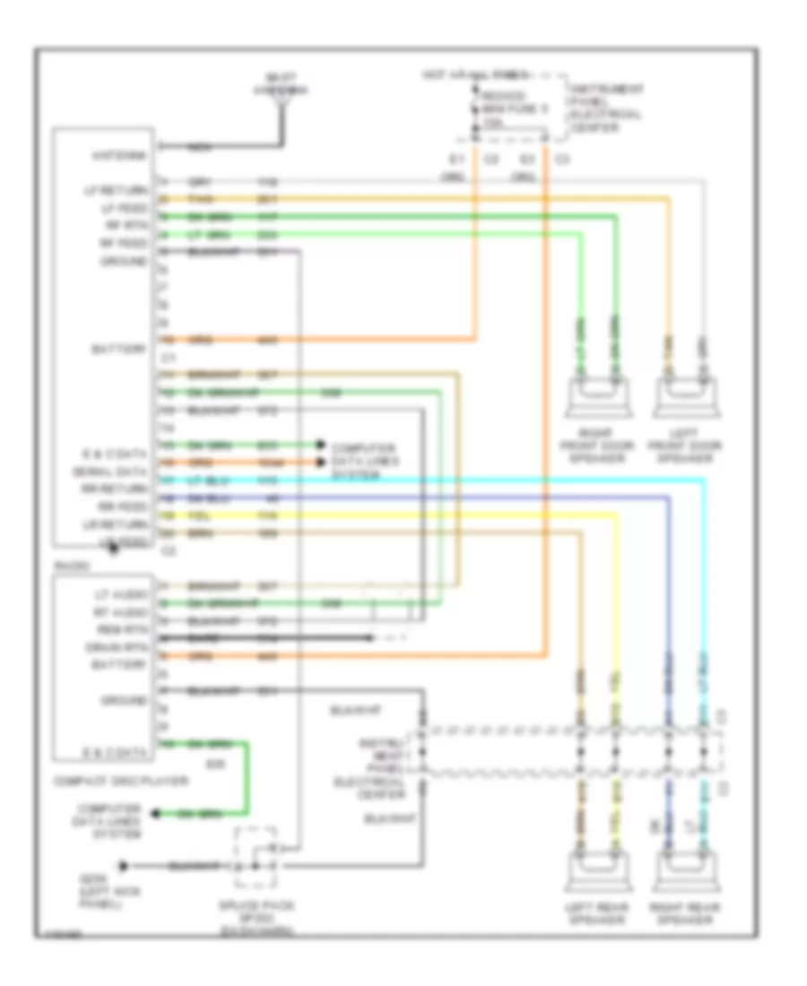 https://portal-diagnostov.com/license.html
Automotive Electricians Portal FZCO
Automotive Electricians Portal FZCO
https://portal-diagnostov.com/license.html
https://portal-diagnostov.com/license.html
Automotive Electricians Portal FZCO
Automotive Electricians Portal FZCOList of elements for Radio Wiring Diagrams, without Bose System for Chevrolet Corvette 1999:
- A10
- Antenna
- B10
- Bare
- Battery
- Compact disc player
- Computer data lines system
- Drain rtn
- E & c data
- E11
- G200 (left kick panel)
- Ground
- Hot at all times
- Instru- ment panel electrical center
- Instrument panel electrical center
- Left front door speaker
- Left rear speaker
- Lf feed
- Lf return
- Lr feed
- Lr return
- Lt audio
- Mast antenna
- Nca
- Radio
- Rdo/cd mini fuse 5 15a
- Rem rtn
- Rf feed
- Rf rtn
- Right front door speaker
- Right rear speaker
- Rr feed
- Rr return
- Rt audio
- Serial data
- Splice pack sp203 (dash harn)
- Tan
- Tan d
SHIFT INTERLOCKS
Shift Interlock Wiring Diagram for Chevrolet Corvette 1999
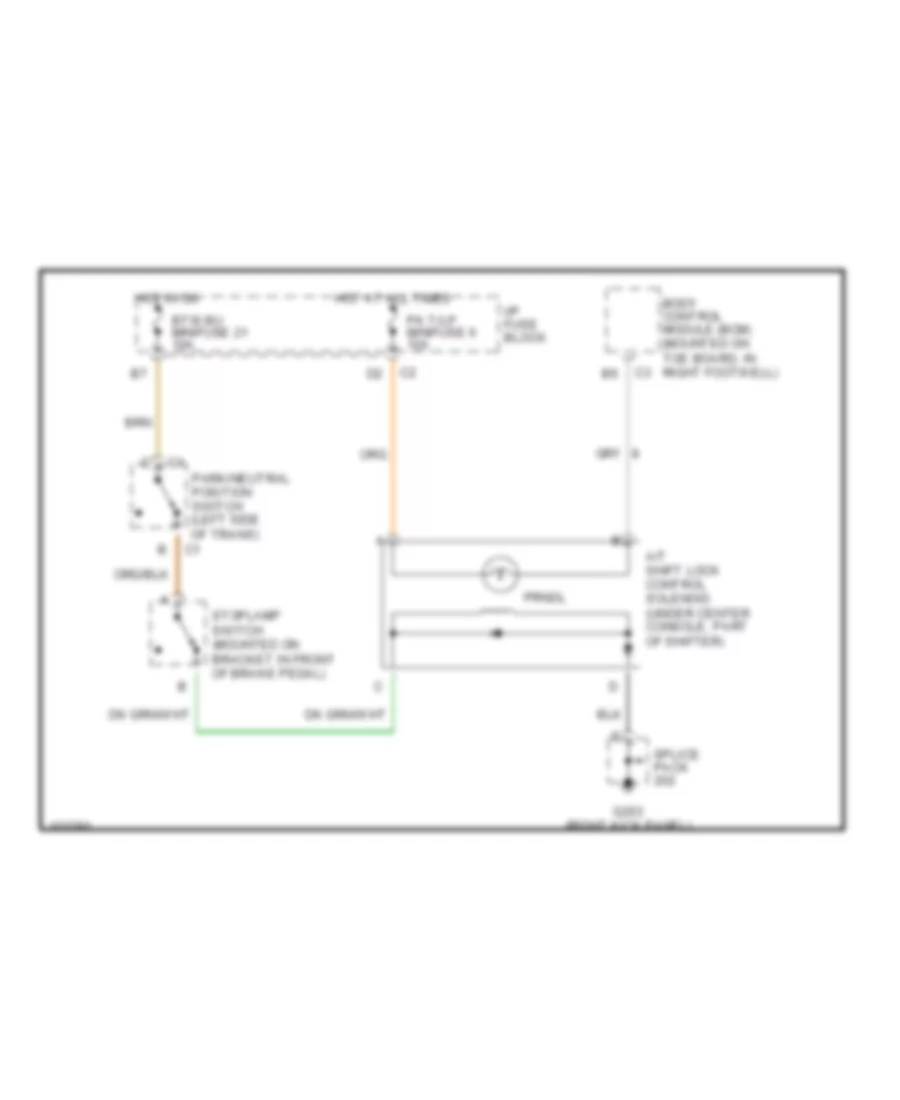 https://portal-diagnostov.com/license.html
Automotive Electricians Portal FZCO
Automotive Electricians Portal FZCO
https://portal-diagnostov.com/license.html
https://portal-diagnostov.com/license.html
Automotive Electricians Portal FZCO
Automotive Electricians Portal FZCOList of elements for Shift Interlock Wiring Diagram for Chevrolet Corvette 1999:
- A/t shift lock control solenoid (under center console, part of shifter)
- Body control module (bcm) (mounted on toe board, in right footwell)
- Btsi bu minifuse 21 10a
- G203 (right kick panel)
- Hot at all times
- Hot in on
- I/p fuse block
- Park/neutral position switch (left side of trans)
- Pk t/lp minifuse 6 10a
- Prndl
- Splice pack
- Stoplamp switch (mounted on bracket in front of brake pedal)
STARTING/CHARGING
Charging Wiring Diagram for Chevrolet Corvette 1999
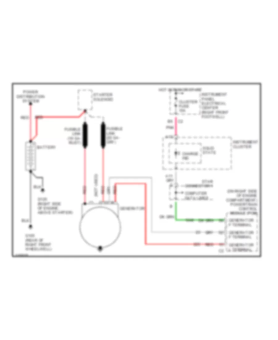 https://portal-diagnostov.com/license.html
Automotive Electricians Portal FZCO
Automotive Electricians Portal FZCO
https://portal-diagnostov.com/license.html
https://portal-diagnostov.com/license.html
Automotive Electricians Portal FZCO
Automotive Electricians Portal FZCOList of elements for Charging Wiring Diagram for Chevrolet Corvette 1999:
- (not used)
- (on right side of engine compartment) powertrain control module (pcm)
- A13
- Battery
- Charge ind
- Cluster fuse 10a
- Computer data lines
- Fusible link (10 ga- rust)
- G105 (rear of right front wheelwell)
- G120 (right side of engine, above starter)
- Generator
- Generator f terminal
- Generator l terminal
- Hot in run or start
- Instrument cluster
- Instrument panel electrical center (right front footwell)
- Pnk
- Power distribution system
- Red
- Solid state
- Star connector 1
- Starter solenoid
Starting Wiring Diagram for Chevrolet Corvette 1999
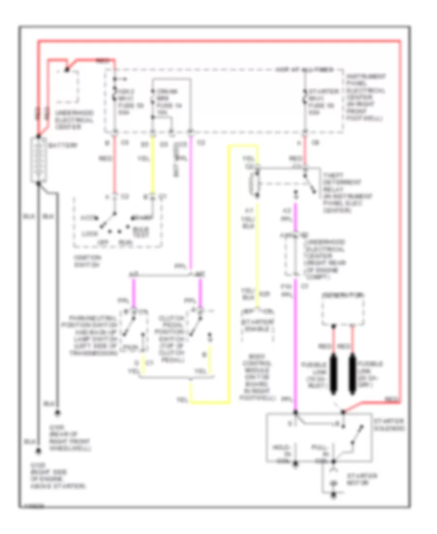 https://portal-diagnostov.com/license.html
Automotive Electricians Portal FZCO
Automotive Electricians Portal FZCO
https://portal-diagnostov.com/license.html
https://portal-diagnostov.com/license.html
Automotive Electricians Portal FZCO
Automotive Electricians Portal FZCOList of elements for Starting Wiring Diagram for Chevrolet Corvette 1999:
- A/t
- A10
- Accy
- Battery
- Body control module (on toe board, in right footwell)
- Bulb test
- Clutch pedal position switch (top of clutch pedal)
- Crank mini fuse 14 10a
- D5 (not used)
- F10
- Fusible link (10 ga- rust)
- G c1
- G105 (rear of right front wheelwell)
- G120 (right side of engine, above starter)
- Generator
- Hold- in coil
- Hot at all times
- Ign 2 maxi fuse 50 60a
- Ignition switch
- Instrument panel electrical center (in right front footwell)
- Lock
- M/t
- Off
- Park/neutral position switch and back-up lamp switch (left side of pk/n
- Pull- in coil
- Red
- Run
- Start
- Starter enable
- Starter maxi fuse 50 60a
- Starter motor
- Starter solenoid
- Theft deterrent relay (in instrument panel elec center)
- Transmission)
- Underhood electrical center
- Underhood electrical center (right rear of engine compt)
SUPPLEMENTAL RESTRAINTS
Supplemental Restraint Wiring Diagram for Chevrolet Corvette 1999
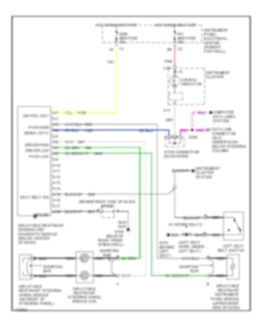 https://portal-diagnostov.com/license.html
Automotive Electricians Portal FZCO
Automotive Electricians Portal FZCO
https://portal-diagnostov.com/license.html
https://portal-diagnostov.com/license.html
Automotive Electricians Portal FZCO
Automotive Electricians Portal FZCOList of elements for Supplemental Restraint Wiring Diagram for Chevrolet Corvette 1999:
- (behind right side of dash) sp208
- (left seat harn, under left seat)
- A nca
- A10
- A11
- A12
- A13
- A14
- A15
- A16
- A17
- A18
- Air bag indicator
- Bar
- Computer data lines system
- Connector (dlc) (under dash, below steering column)
- Driver high
- Driver low
- G105 (rear of right front wheelwell)
- G312 (behind left seat)
- Ground
- Hot in run or start
- Ign pos volt
- Inflatable restraint instrument panel module (upper right side of dash)
- Inflatable restraint sensing and diagnostic module (below center of dash)
- Inflatable restraint steering wheel module (on front of steering wheel)
- Inflatable restraint steering wheel module coil
- Instrument cluster
- Instrument cluster system
- Instrument panel electrical center (in right footwell)
- Ipc mini fuse 10a
- Left seat belt switch
- Nca
- Pass high
- Pass low
- Pnk
- S206
- S301
- Sdm mini fuse 15a
- Seat belt sig
- Serial data
- Shorting
- Shorting bar
- Star connector (dash harn)
- W/ sport seats
TRANSMISSION
5.7L
5.7L VIN G, A/T Wiring Diagram for Chevrolet Corvette 1999
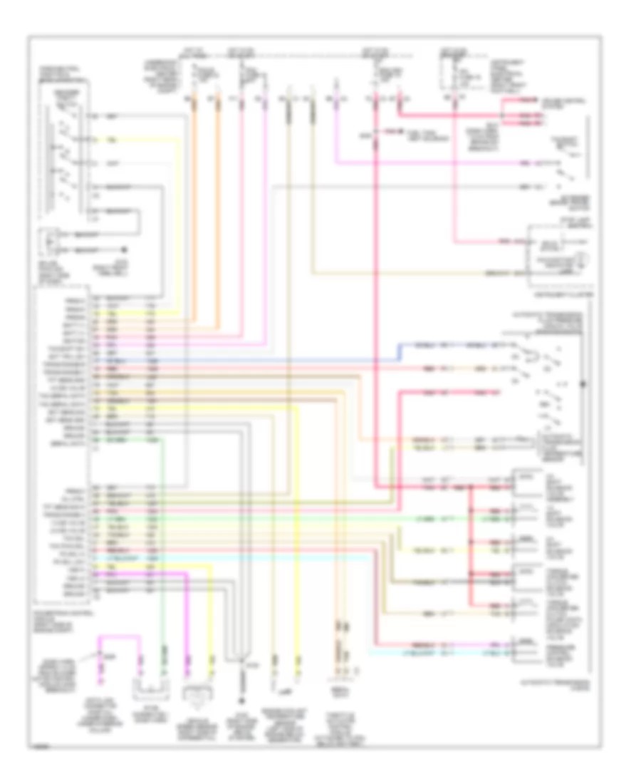 https://portal-diagnostov.com/license.html
Automotive Electricians Portal FZCO
Automotive Electricians Portal FZCO
https://portal-diagnostov.com/license.html
https://portal-diagnostov.com/license.html
Automotive Electricians Portal FZCO
Automotive Electricians Portal FZCOList of elements for 5.7L VIN G, A/T Wiring Diagram for Chevrolet Corvette 1999:
- (dash harn, approx 14 cm from blower motor control module conn breakout)
- 1-2 shift solenoid valve
- 1-2 ss valve
- 2-3 shift solenoid valve
- 2-3 ss valve
- 3-2 shift solenoid valve assembly
- 3-2 ss valve
- A13
- Automatic transmission (4l60-e)
- Automatic transmission fluid pressure manual valve position switch
- Automatic transmission fluid temperature sensor
- B16
- B6 pnk
- B7 pnk
- Batt (+)
- Cruise control system
- Data link connector (partial) (under dash, under steering column)
- Decoder parity switch
- Ecm ign1 fuse 19 10a
- Ect sens gnd
- Ect sens sig
- Engine coolant temperature sensor (left side of engine below generator)
- Ext trvl sw
- Extended brake travel switch
- F11 pnk
- F2 pnk
- Fuel tank vent solenoid
- G103 (right front weelwell)
- G120 (right side of engine, above starter)
- Ground
- Hot at all times
- Hot in on or start
- Ignition
- Instrument cluster
- Instrument panel electrical center (right front footwell)
- Ipc fuse 19 10a
- Malfunction indicator lamp
- Mil ctrl
- Park/neutral position & back up switch
- Pc sol hi
- Pc sol low
- Pcm b fuse 23 10a
- Pcm fuse 16 10a
- Pnk
- Powertrain control module (right side of engine compt)
- Pressure control solenoid valve
- Prnd-a
- Prnd-b
- Prnd-c
- Prnd-p
- Red
- Rev
- S120
- S206
- S213 (dash harn, 7.5 cm from brake sw breakout)
- S400
- Serial data
- Solid state
- Splice pack 208 (right side of dash)
- Star connector 1 (dash harn)
- Stop lamp switch
- Tac serial data
- Tan
- Tcc pwm sol
- Tcc sol
- Tcc/shift sw
- Tcc/shift switch
- Tft sens gnd
- Tft sens sig in
- Throttle actuator control module (attached to pcm, below battery)
- Torque converter clutch pulse width modulation solenoid valve
- Torque converter clutch solenoid valve
- Trans range a
- Trans range b
- Trans range c
- Underhood electrical center (right rear of engine compt)
- Vehicle speed sensor (right side of differential)
- Vss hi
- Vss lo
5.7L VIN G, M/T Wiring Diagram for Chevrolet Corvette 1999
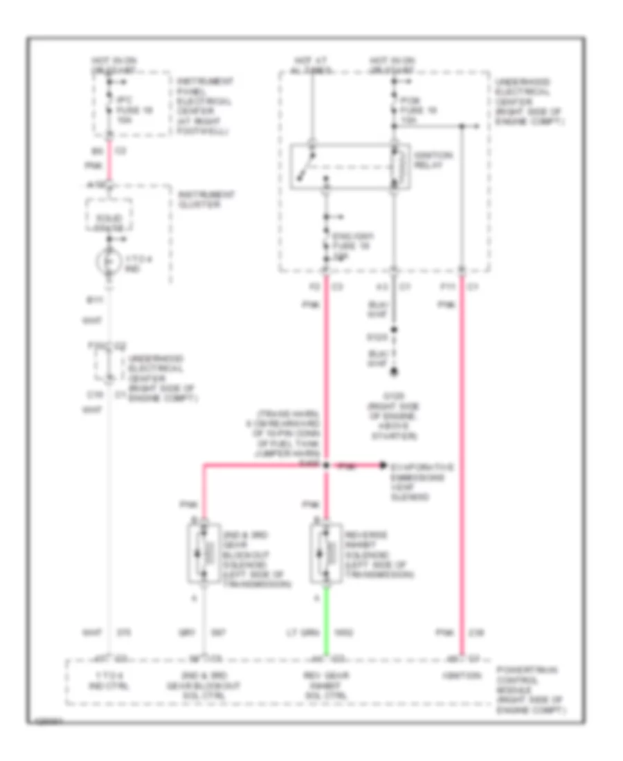 https://portal-diagnostov.com/license.html
Automotive Electricians Portal FZCO
Automotive Electricians Portal FZCO
https://portal-diagnostov.com/license.html
https://portal-diagnostov.com/license.html
Automotive Electricians Portal FZCO
Automotive Electricians Portal FZCOList of elements for 5.7L VIN G, M/T Wiring Diagram for Chevrolet Corvette 1999:
- (trans harn, 6 cm rearward of 10-pin conn of fuel tank jumper harn) s400
- 1 to 4 ind
- 1 to 4 ind ctrl
- 2nd & 3rd gear blockout sol ctrl
- 2nd & 3rd gear blockout solenoid (left side of transmission)
- A13
- B11
- C10
- Eng ign1 fuse 19 10a
- Evaporative emmissions vent slenoid
- F10
- F11
- G120 (right side of engine, above starter)
- Hot at al times
- Hot in on or start
- Ignition
- Ignition relay
- Instrument cluster
- Instrument panel electrical center (at right footwell)
- Ipc fuse 19 10a
- Pcm fuse 16 10a
- Pnk
- Powertrain control module (right side of engine compt)
- Rev gear inhibit sol ctrl
- Reverse inhibit solenoid (left side of transmission)
- S120
- Solid state
- Underhood electrical center (right side of engine compt)
TRUNK, TAILGATE, FUEL DOOR
Folding Top Lid Release Wiring Diagram for Chevrolet Corvette 1999
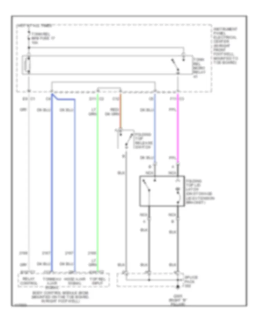 https://portal-diagnostov.com/license.html
Automotive Electricians Portal FZCO
Automotive Electricians Portal FZCO
https://portal-diagnostov.com/license.html
https://portal-diagnostov.com/license.html
Automotive Electricians Portal FZCO
Automotive Electricians Portal FZCOList of elements for Folding Top Lid Release Wiring Diagram for Chevrolet Corvette 1999:
- Body control module (bcm) (mounted on the toe board, in right footwell)
- C1 b12
- C12
- C13
- C2 c11
- D11 c2
- E9 c1
- F11 c3
- Folding top lid latch (on stowage
- Folding top release switch
- G305 (right "b" pillar)
- Hood ajar signal
- Hot at all times
- Instrument panel electrical center (in right front footwell, mounted to toe board)
- Lid extension bracket)
- Nca
- Relay control
- Splice pack
- Tonn rel micro relay
- Tonn rel mini fuse 17 10a
- Tonneau ajar signal
- Top rel input
Fuel Door Release Wiring Diagram for Chevrolet Corvette 1999
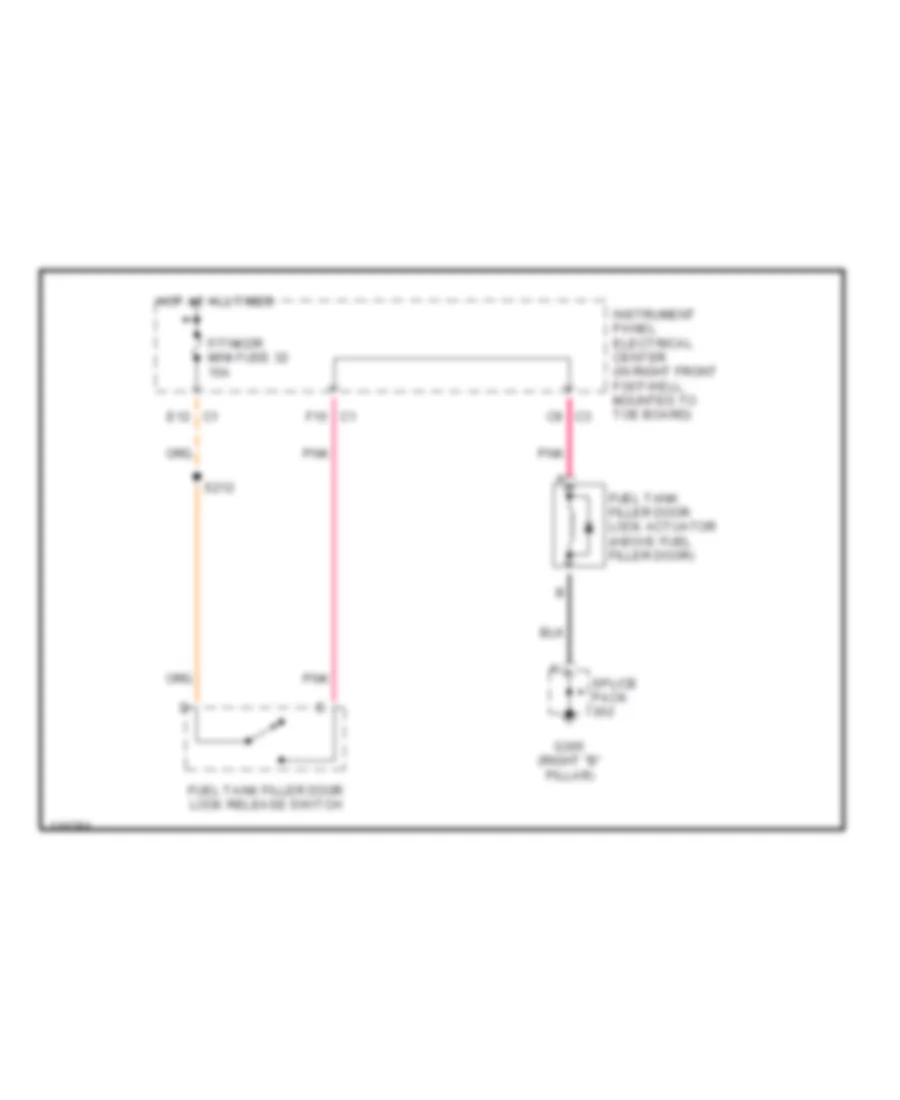 https://portal-diagnostov.com/license.html
Automotive Electricians Portal FZCO
Automotive Electricians Portal FZCO
https://portal-diagnostov.com/license.html
https://portal-diagnostov.com/license.html
Automotive Electricians Portal FZCO
Automotive Electricians Portal FZCOList of elements for Fuel Door Release Wiring Diagram for Chevrolet Corvette 1999:
- C9 c3
- E12 c1
- F/tnkdr mini fuse 32 15a
- F10 c1
- Fuel tank filler door lock actuator (above fuel filler door)
- Fuel tank filler door lock release switch
- G305 (right "b" pillar)
- Hot at all times
- Instrument panel electrical center (in right front footwell, mounted to toe board)
- Pnk
- S212
- Splice pack
Hatch Release Wiring Diagram for Chevrolet Corvette 1999
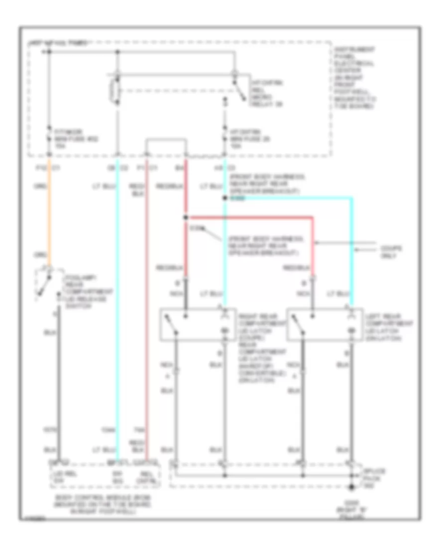 https://portal-diagnostov.com/license.html
Automotive Electricians Portal FZCO
Automotive Electricians Portal FZCO
https://portal-diagnostov.com/license.html
https://portal-diagnostov.com/license.html
Automotive Electricians Portal FZCO
Automotive Electricians Portal FZCOList of elements for Hatch Release Wiring Diagram for Chevrolet Corvette 1999:
- (front body harness, near right rear speaker breakout)
- A9 c3
- Body control module (bcm) (mounted on the toe board, in right footwell)
- C1 b9
- C2 c12
- C2 d9
- C8 c2
- Coupe only
- F/tnkdr mini fuse #32 15a
- F1 c1
- F12 c1
- Foglamp/ rear compartment lid release switch
- G305 (right "b" pillar)
- Hot at all times
- Htchtrk mini fuse 26 10a
- Htchtrk rel micro relay 39
- Instrument panel electrical center (in right front footwell, mounted to toe board)
- Left rear compartment lid latch (on latch)
- Lid rel sw
- Nca
- Rel cntrl
- Right rear compartment lid latch (coupe) rear compartment lid latch (hardtop/ convertible) (on latch)
- S304
- Speaker breakout) s302
- Splice pack
- Sw sig
WARNING SYSTEMS
Warning System Wiring Diagrams for Chevrolet Corvette 1999
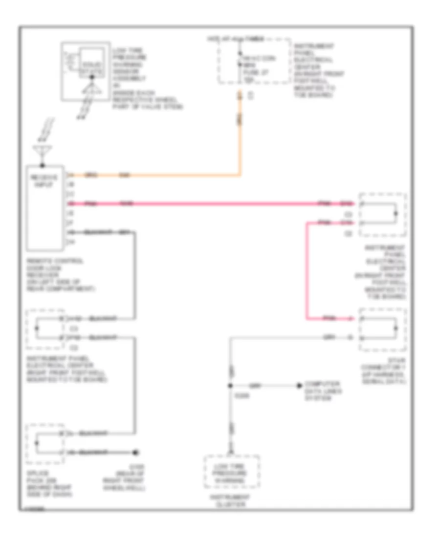 https://portal-diagnostov.com/license.html
Automotive Electricians Portal FZCO
Automotive Electricians Portal FZCO
https://portal-diagnostov.com/license.html
https://portal-diagnostov.com/license.html
Automotive Electricians Portal FZCO
Automotive Electricians Portal FZCOList of elements for Warning System Wiring Diagrams for Chevrolet Corvette 1999:
- (inside each respective wheel part of valve stem)
- A11
- A12
- C10
- Computer data lines system
- D12
- F12
- Footwell,
- G105 (rear of right front wheelwell)
- Hot at all times
- Hvac con mini fuse 27 10a
- Instrument cluster
- Instrument panel electrical center (in right front
- Instrument panel electrical center (in right front footwell, mounted to toe board)
- Instrument panel electrical center (right front footwell mounted to toe board)
- Low tire pressure warning
- Low tire pressure warning sensor assembly (4)
- Mounted to toe board)
- Pnk
- Receive input
- Remote control door lock receiver (on left side of rear compartment)
- S206
- Solid state
- Splice pack 208 (behind right side of dash)
- Star connector 1 (i/p harness, serial data)
WIPER/WASHER
Wiper/Washer Wiring Diagram for Chevrolet Corvette 1999
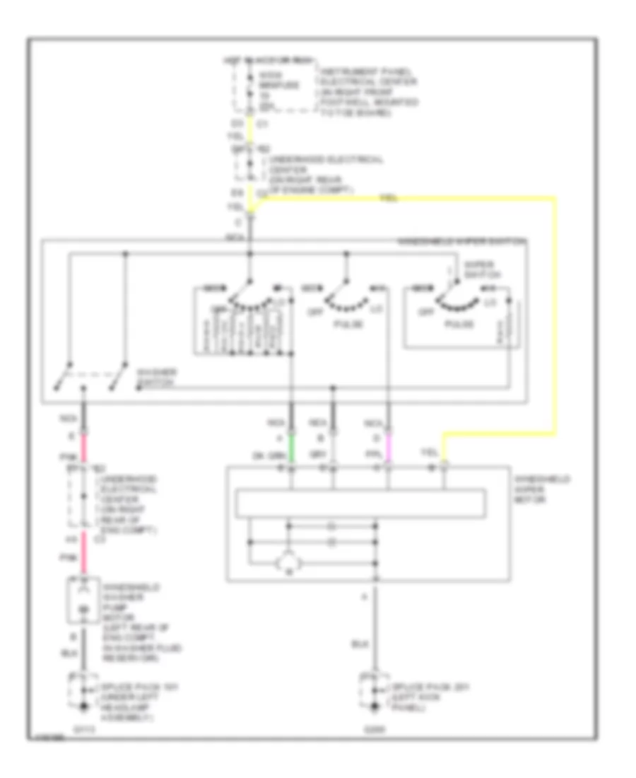 https://portal-diagnostov.com/license.html
Automotive Electricians Portal FZCO
Automotive Electricians Portal FZCO
https://portal-diagnostov.com/license.html
https://portal-diagnostov.com/license.html
Automotive Electricians Portal FZCO
Automotive Electricians Portal FZCOList of elements for Wiper/Washer Wiring Diagram for Chevrolet Corvette 1999:
- G113
- G200
- Hot in acc or run
- Instrument panel electrical center (in right front footwell, mounted to toe board)
- Mist
- Nca
- Off
- Pnk
- Pnk f6
- Pulse
- Splice pack 101 (under left headlamp assembly)
- Splice pack 201 (left kick panel)
- Underhood electrical center (on right rear of eng compt)
- Underhood electrical center (on right rear of engine compt)
- Washer switch
- Windshield washer pump motor (left rear of eng compt, in washer fluid reservoir)
- Windshield wiper motor
- Windshield wiper switch
- Wiper switch
- Wsw minifuse 25a

 Čeština
 Dansk
Dansk Deutsch
 Ελληνικά
 English
 English
 Español
 Suomi
Suomi Français
 Français
 עברית
עברית Hrvatski
 Magyar
 Italiano
 한국어
한국어 Nederlands
 Polski
 Português
 Português
 Română
 Русский
 Slovenčina
 Slovenščina
 Svenska
 Türkçe
 中文 (中国)
