AIR CONDITIONING
2.0L
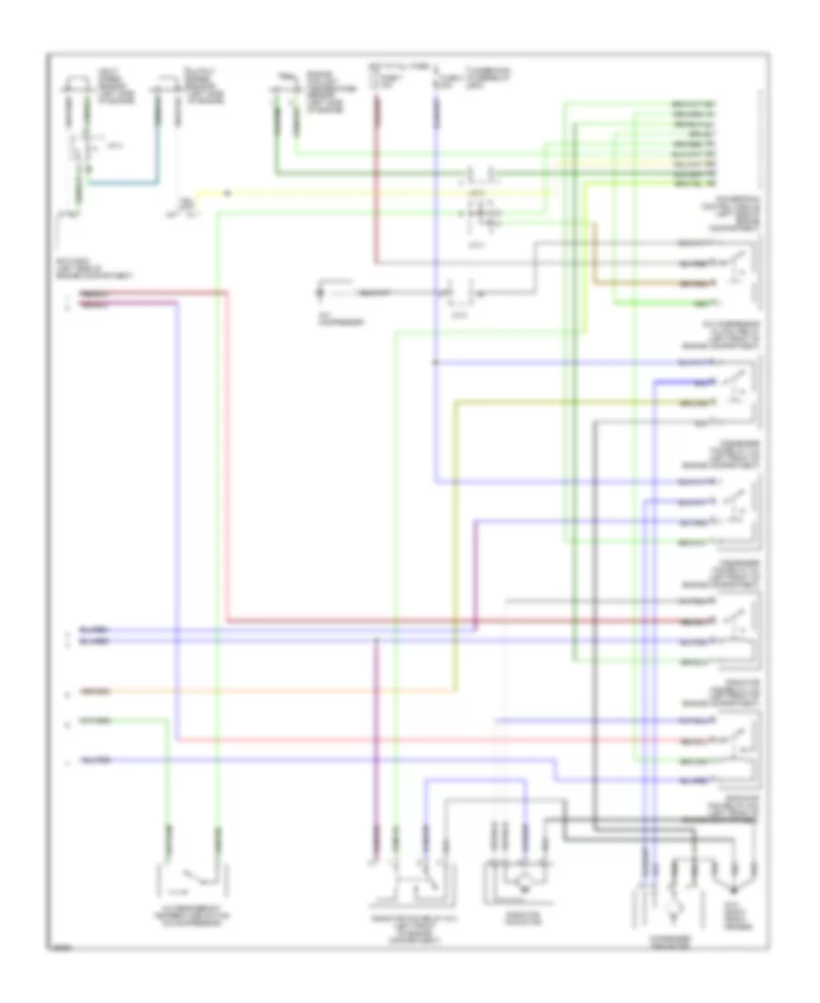
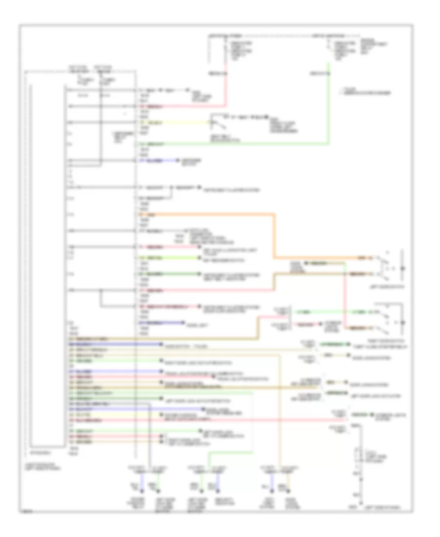
2.0L, A/C Wiring Diagram, A/T (1 of 2) for Dodge Avenger 1997
 https://portal-diagnostov.com/license.html
Automotive Electricians Portal FZCO
Automotive Electricians Portal FZCO
https://portal-diagnostov.com/license.html
https://portal-diagnostov.com/license.html
Automotive Electricians Portal FZCO
Automotive Electricians Portal FZCO
List of elements for 2.0L, A/C Wiring Diagram, A/T (1 of 2) for Dodge Avenger 1997:
- (behind center of i/p) g206
- A/c switch
- A/c switch illumination
- Acc
- Automatic compressor ecm (below right side of i/p)
- B-41
- B-42
- B-63
- Blower motor
- Blower motor relay
- Blower resistor (behind right side of i/p)
- Blower switch
- Defroster switch
- Dual pressure switch (right front of engine compartment)
- Fuse 10a
- Fuse 30a
- Fusible link 6 30a
- G206 (behind center of i/p)
- Hot at all times
- Hot in run
- Ignition switch
- Interior lights system
- Junction block (below left side of i/p)
- Lock
- Off
- Run
- Start
- Underhood fuse/relay box
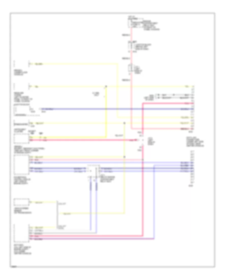
2.0L, A/C Wiring Diagram, A/T (2 of 2) for Dodge Avenger 1997
 https://portal-diagnostov.com/license.html
Automotive Electricians Portal FZCO
Automotive Electricians Portal FZCO
https://portal-diagnostov.com/license.html
https://portal-diagnostov.com/license.html
Automotive Electricians Portal FZCO
Automotive Electricians Portal FZCOList of elements for 2.0L, A/C Wiring Diagram, A/T (2 of 2) for Dodge Avenger 1997:
- (left side of engine compartment)
- A/c compressor
- A/c compressor clutch relay (left front of engine compartment)
- Condenser fan motor
- Condenser fan relay (hi) (left front of engine compartment)
- Condenser fan relay (lo) (left front of engine compartment)
- Eatx ecm (left side of engine compart- ment)
- Engine coolant temperature sensor (right side of engine)
- Fin thermo sensor (in plenum below right side of i/p)
- Fuse 7 10a
- Fuse 8 20a
- G101 (right front fender)
- Hot at all times
- Input speed sensor (left side of engine)
- J/c
- J/c 2
- J/c 3
- J/c 4
- Output speed sensor (left side of engine)
- Powertrain control module
- Radiator fan motor
- Radiator fan relay (hi) (left front of engine compartment)
- Radiator fan relay (lo) (left front of engine compartment)
- Revolution pick-up sensor (on compressor)
- Underhood fuse/relay box
2.0L, A/C Wiring Diagram, M/T (1 of 2) for Dodge Avenger 1997
 https://portal-diagnostov.com/license.html
Automotive Electricians Portal FZCO
Automotive Electricians Portal FZCO
https://portal-diagnostov.com/license.html
https://portal-diagnostov.com/license.html
Automotive Electricians Portal FZCO
Automotive Electricians Portal FZCOList of elements for 2.0L, A/C Wiring Diagram, M/T (1 of 2) for Dodge Avenger 1997:
- A/c switch
- A/c switch illumination
- Acc
- Automatic compressor ecm (below right side of i/p)
- B-41
- B-42
- B-63
- Blower motor
- Blower motor relay
- Blower resistor (behind right side of i/p)
- Blower switch
- Defroster switch
- Dual pressure switch (right front of engine compartment)
- Fuse 10a
- Fuse 30a
- Fusible link 6 30a
- G206 (behind center of i/p)
- Hot at all times
- Hot in run
- Ignition switch
- Interior lights system
- Junction block (below left side of i/p)
- Lock
- Off
- Run
- Start
- Underhood fuse/relay box
2.0L, A/C Wiring Diagram, M/T (2 of 2) for Dodge Avenger 1997
 https://portal-diagnostov.com/license.html
Automotive Electricians Portal FZCO
Automotive Electricians Portal FZCO
https://portal-diagnostov.com/license.html
https://portal-diagnostov.com/license.html
Automotive Electricians Portal FZCO
Automotive Electricians Portal FZCOList of elements for 2.0L, A/C Wiring Diagram, M/T (2 of 2) for Dodge Avenger 1997:
- (left side of engine compartment)
- A/c compressor
- A/c compressor clutch relay (left front of engine compartment)
- Condenser fan motor
- Condenser fan relay (hi) (left front of engine compartment)
- Condenser fan relay (lo) (left front of engine compartment)
- Engine coolant temperature sensor (right side of engine)
- Fin thermo sensor (in plenum below right side of i/p)
- Fuse 7 10a
- Fuse 8 20a
- G101 (right front fender)
- Hot at all times
- J/c 2
- J/c 3
- J/c 4
- Powertrain control module
- Radiator fan motor
- Radiator fan relay (hi) (left front of engine compartment)
- Radiator fan relay (lo) (left front of engine compartment)
- Revolution pick-up sensor (on compressor)
- Underhood fuse/relay box
- Vehicle speed sensor (on side of trans- axle)
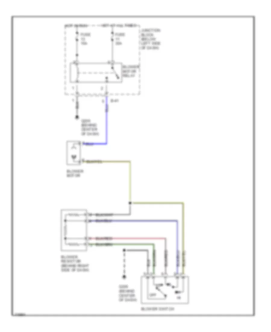
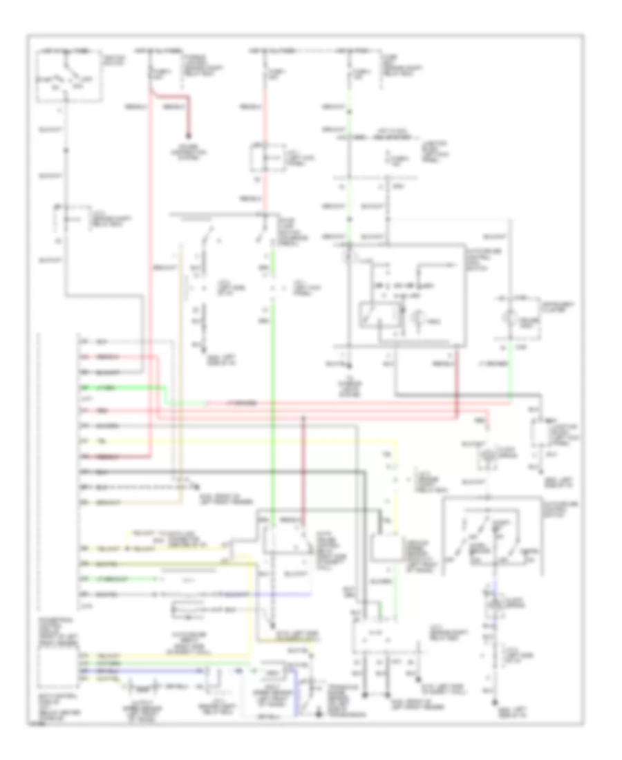
Heater Wiring Diagram for Dodge Avenger 1997
 https://portal-diagnostov.com/license.html
Automotive Electricians Portal FZCO
Automotive Electricians Portal FZCO
https://portal-diagnostov.com/license.html
https://portal-diagnostov.com/license.html
Automotive Electricians Portal FZCO
Automotive Electricians Portal FZCOList of elements for Heater Wiring Diagram for Dodge Avenger 1997:
- B-41
- Blower motor
- Blower motor relay
- Blower resistor (behind right side of dash)
- Blower switch
- Fuse 10a
- Fuse 30a
- G206 (behind center of dash)
- Hot at all times
- Hot in run
- Junction block (below left side of dash)
- Off
2.5L
2.5L, A/C Wiring Diagram (1 of 2) for Dodge Avenger 1997
 https://portal-diagnostov.com/license.html
Automotive Electricians Portal FZCO
Automotive Electricians Portal FZCO
https://portal-diagnostov.com/license.html
https://portal-diagnostov.com/license.html
Automotive Electricians Portal FZCO
Automotive Electricians Portal FZCOList of elements for 2.5L, A/C Wiring Diagram (1 of 2) for Dodge Avenger 1997:
- (behind center of i/p) g206
- A/c switch
- A/c switch illumination
- Acc
- Automatic compressor ecm (below right side of i/p)
- B-41
- B-42
- B-63
- Blower motor
- Blower motor relay
- Blower resistor (behind right side of i/p)
- Blower switch
- Defroster switch
- Dual pressure switch (right front of engine compartment)
- Fuse 10a
- Fuse 30a
- Fusible link 6 30a
- G206 (behind center of i/p)
- Hot at all times
- Hot in run
- Ignition switch
- Interior lights system
- Junction block (below left side of i/p)
- Lock
- Off
- Run
- Start
- Underhood fuse/relay box
2.5L, A/C Wiring Diagram (2 of 2) for Dodge Avenger 1997
 https://portal-diagnostov.com/license.html
Automotive Electricians Portal FZCO
Automotive Electricians Portal FZCO
https://portal-diagnostov.com/license.html
https://portal-diagnostov.com/license.html
Automotive Electricians Portal FZCO
Automotive Electricians Portal FZCOList of elements for 2.5L, A/C Wiring Diagram (2 of 2) for Dodge Avenger 1997:
- A/c compressor
- A/c compressor clutch relay (left front of engine compartment)
- A/c refrigerant temperature switch (on compressor)
- Condenser fan motor
- Condenser fan relay (hi) (left front of engine compartment)
- Condenser fan relay (lo) (left front of engine compartment)
- Eatx ecm (left side of engine compartment)
- Engine coolant temperature sensor (left side of engine)
- Fuse 7 10a
- Fuse 8 20a
- G101 (right front fender)
- Hot at all times
- Input speed sensor (left side of engine)
- J/c 2
- J/c 3
- J/c 4
- Output speed sensor (left side of engine)
- Powertrain control module (left side of engine compartment)
- Radiator fan motor
- Radiator fan relay (hi1) (left front of engine compartment)
- Radiator fan relay (hi2) (left front of engine compartment)
- Radiator fan relay (lo) (left front of engine compartment)
- Underhood fuse/relay box
Heater Wiring Diagram for Dodge Avenger 1997
 https://portal-diagnostov.com/license.html
Automotive Electricians Portal FZCO
Automotive Electricians Portal FZCO
https://portal-diagnostov.com/license.html
https://portal-diagnostov.com/license.html
Automotive Electricians Portal FZCO
Automotive Electricians Portal FZCOList of elements for Heater Wiring Diagram for Dodge Avenger 1997:
- B-41
- Blower motor
- Blower motor relay
- Blower resistor (behind right side of dash)
- Blower switch
- Fuse 10a
- Fuse 30a
- G206 (behind center of dash)
- Hot at all times
- Hot in run
- Junction block (below left side of dash)
- Off
ANTI-LOCK BRAKES
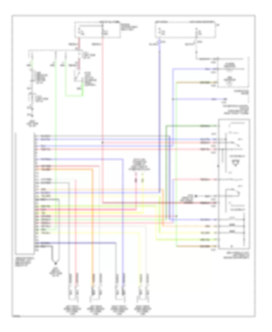
Anti-lock Brake Wiring Diagrams for Dodge Avenger 1997
 https://portal-diagnostov.com/license.html
Automotive Electricians Portal FZCO
Automotive Electricians Portal FZCO
https://portal-diagnostov.com/license.html
https://portal-diagnostov.com/license.html
Automotive Electricians Portal FZCO
Automotive Electricians Portal FZCOList of elements for Anti-lock Brake Wiring Diagrams for Dodge Avenger 1997:
- g100 (front of left front fender)
- j/c 2 (left side of i/p)
- A-32
- A-33
- A-78
- Abs electronic control unit (behind right side of i/p)
- Abs hydraulic unit (left front of engine compartment)
- Abs indicator
- Abs resistor (behind center of i/p)
- B-54
- C-04
- C-06
- Charge indicator
- Combination meter
- Data link connector (under i/p, right side of steering column)
- Engine compartment relay box
- F1 15a
- F13 10a
- F8 10a
- Fl7 60a
- G201 (below right side of i/p)
- G202 (left side of i/p)
- Hot at all times
- Hot in run
- Hot in run or start
- J/b
- J/c 1 (left side of i/p)
- Left front speed sensor (on wheel hub)
- Left rear speed sensor (on wheel hub)
- Motor
- Motor relay
- Nca
- Pnk
- Powertrain control module (forward of left front strut tower)
- Right front speed sensor (on wheel hub)
- Right rear speed sensor (on wheel hub)
- Stop light switch (on brake pedal support)
- Valve relay
ANTI-THEFT
Anti-theft Wiring Diagram for Dodge Avenger 1997
 https://portal-diagnostov.com/license.html
Automotive Electricians Portal FZCO
Automotive Electricians Portal FZCO
https://portal-diagnostov.com/license.html
https://portal-diagnostov.com/license.html
Automotive Electricians Portal FZCO
Automotive Electricians Portal FZCOList of elements for Anti-theft Wiring Diagram for Dodge Avenger 1997:
- (center of firewall)
- (center rear of trunk) g407
- * b-47
- * b-49
- * b-50
- * b-50 b-42 **
- * b-51 b-43 **
- * b-66 b-54 **
- * b-69 b-57 **
- * b-75 b-63 **
- * f11 f10 10a
- * g406 (near liftgate latch)
- ** b-39
- ** b-41
- ** b-42
- A/t
- Acc
- B-48 * b-40
- Data link connector (under left side of dash, near center console)
- Diode (left side of dash)
- Door locks system
- Engine compartment relay box
- Etacs ecu
- F5 10a
- Fuse 8 10a
- Fuse 9 20a
- G101 (front of right front fender)
- G121 g116 (left side of firewall)
- G202 (left side of dash)
- Headlights system (headlight relay coil)
- Hood switch * (talon only)
- Horn system (horn relay coil)
- Hot at all times
- Hot in acc or run
- Hot in run
- Ignition switch
- Instrument cluster
- Interior lights system
- J/c 1 (left side of dash)
- J/c 1 (top left of dash)
- J/c 2 (top left of dash)
- Junction block (behind left side of dash)
- Key reminder switch (open when key is removed)
- Keyless entry receiver (forward of left rear wheel well)
- Left door lock actuator switch
- Left door lock key cylinder switch
- Left door switch
- Lock
- M/t
- No connection
- Or start b-49 b-41
- Red
- Right door lock actuator switch
- Right door lock key cylinder switch
- Right door switch
- Run
- Sebring coupe/avenger
- Security lamp
- Start
- Starting/ charging system
- Talon *
- Theft-alarm horn (avenger/sebring - left rear of engine compt) (talon - right rear of engine compt)
- Theft-alarm horn relay (under left side of dash)
- Theft-alarm starter relay (under left side of dash)
- Trunk lid (or) liftgate key cylinder switch
- Trunk lid (or) liftgate switch
- Unlk
- Unlock
BODY COMPUTER
Body Computer Wiring Diagrams for Dodge Avenger 1997
 https://portal-diagnostov.com/license.html
Automotive Electricians Portal FZCO
Automotive Electricians Portal FZCO
https://portal-diagnostov.com/license.html
https://portal-diagnostov.com/license.html
Automotive Electricians Portal FZCO
Automotive Electricians Portal FZCOList of elements for Body Computer Wiring Diagrams for Dodge Avenger 1997:
- (left side of dash)
- (talon)
- **b-30
- **b-39
- **b-40
- **b-41
- **b-43
- **b-53
- **b-54
- **b-57
- **b-63
- *b-38
- *b-47
- *b-48
- *b-49
- *b-51
- *b-65
- *b-66
- *b-69
- *b-75
- Anti- theft system
- Data link connector (left side of dash,
- Dedicated * fuse 11 dedicated fuse 10 10a
- Dedicated * fuse 5 dedicated fuse 4 15a
- Defogger relay coil
- Defogger switch
- Dome light
- Door locks system
- Door locks system (receiver)
- Door locks system (with remote keyless entry)
- Engine compartment relay box
- Etacs ecu
- Fuse 8 10a
- Fuse 9 20a
- G202
- G202 (left side of dash)
- G300 (front floor upper left crossmember)
- Hood switch
- Hot at all times
- Hot in on
- Hot w/ lights on
- Instrument cluster system
- Instrument cluster system (door ajar indicator)
- Instrument cluster system (seat belt indicator)
- Interior lights system
- J/c 2 (left side of dash)
- Junction block (left side of dash)
- Key hole illumination light (talon)
- Key reminder switch
- Left door lock actuator
- Left door lock actuator switch
- Left door lock key cylinder switch
- Left door switch
- Near center console)
- Or acc
- Or start
- Power windows relay
- Power windows relay (with anti-theft)
- Right door lock actuator switch
- Right door lock key cylinder switch
- Right door switch
- Seat belt buckle switch
- Sebring coupe/avenger
- Security indicator
- Talon *
- Theft alarm starter relay
- Trunk lid/liftgate key cylinder switch
- Trunk lid/liftgate switch
- W/ anti- theft
- W/ remote keyless entry
- W/o anti- theft
- W/o remote keyless entry
COMPUTER DATA LINES
Computer Data Lines for Dodge Avenger 1997
 https://portal-diagnostov.com/license.html
Automotive Electricians Portal FZCO
Automotive Electricians Portal FZCO
https://portal-diagnostov.com/license.html
https://portal-diagnostov.com/license.html
Automotive Electricians Portal FZCO
Automotive Electricians Portal FZCOList of elements for Computer Data Lines for Dodge Avenger 1997:
- 2.ol a/t & 2.5l
- 2.ol m/t
- Abs-ecu (except 1998-right kick panel) (1998-left front corner of engine compt)
- B-29
- B-30
- B-39
- B-42
- B-43
- B-63
- C-05
- Data link connectors (under left side of dash, near center console)
- Dedicated fuse 10 10a
- Eatx-ecm (2.5l-left side of engine compt) (2.0l-under center console)
- Engine compartment relay box (in front of wheel housing)
- Etacs-ecu
- Except
- G202 (left side of dash)
- Hot at all times
- Instrument cluster
- J/c 1 (left side of dash)
- J/c 2 (left side of dash)
- J/c 4 (below engine compartment relay box)
- Junction block
- Junction block (behind left side of dash)
- Pnk
- Powertrain control module (left side of engine compt)
- Receiver (w/rke) (left quarter panel, in front of wheel housing)
- Speedometer
- Srs-ecu (under floor console)
- Vehicle speed sensor (on transmission)
- W/ abs only
COOLING FAN
2.0L
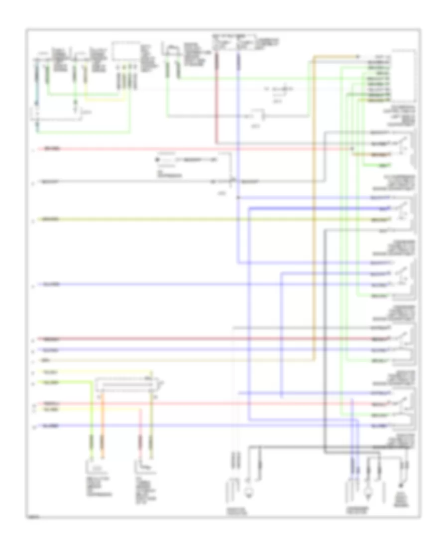
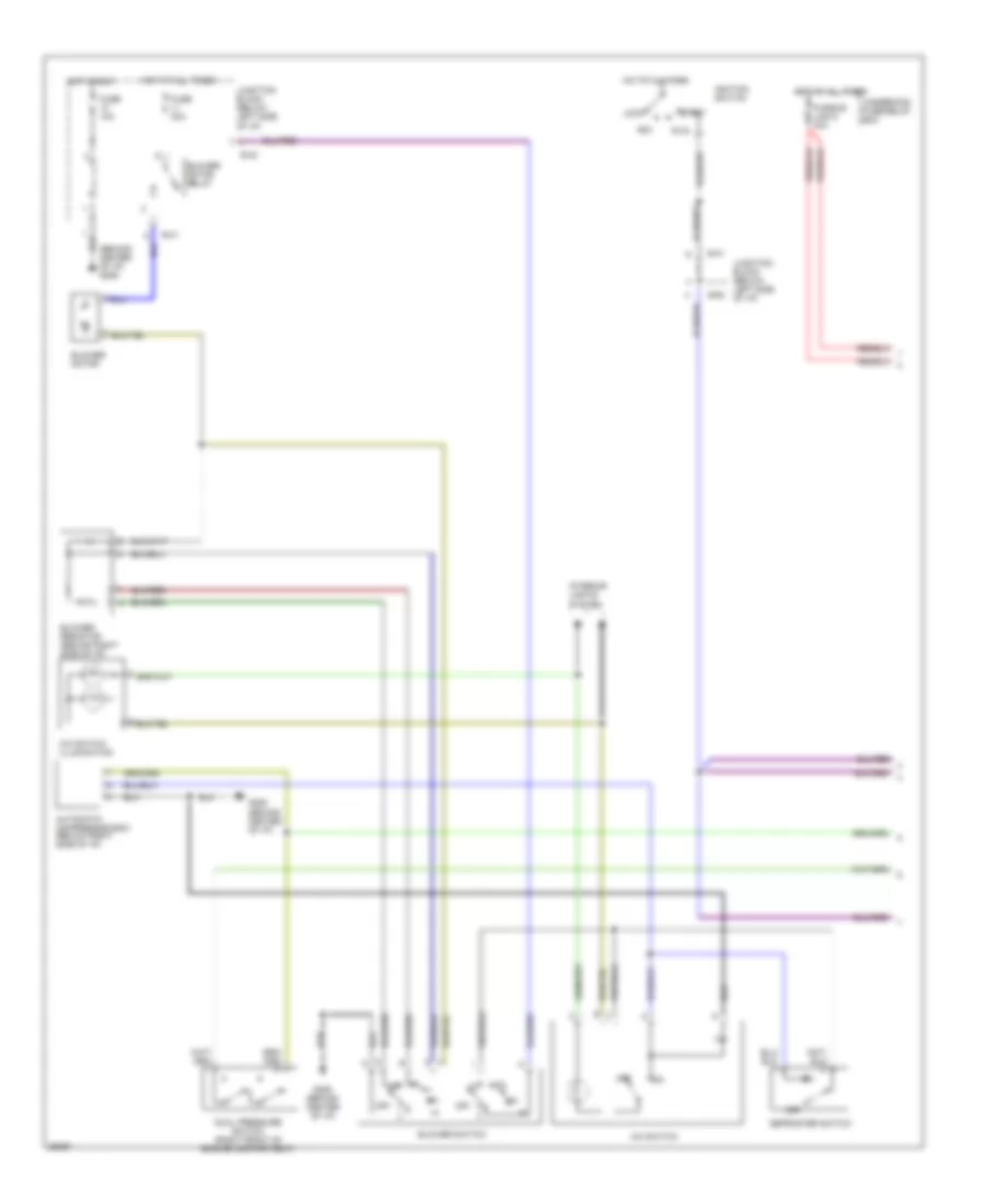
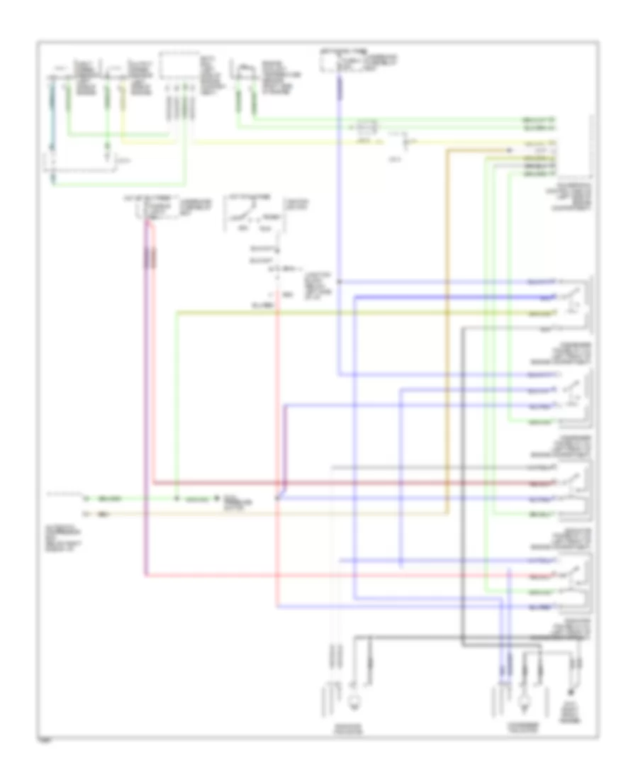
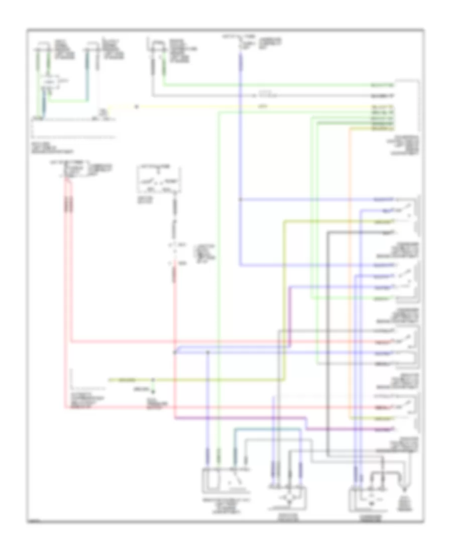
2.0L, Cooling Fan Wiring Diagram, A/T for Dodge Avenger 1997
 https://portal-diagnostov.com/license.html
Automotive Electricians Portal FZCO
Automotive Electricians Portal FZCO
https://portal-diagnostov.com/license.html
https://portal-diagnostov.com/license.html
Automotive Electricians Portal FZCO
Automotive Electricians Portal FZCOList of elements for 2.0L, Cooling Fan Wiring Diagram, A/T for Dodge Avenger 1997:
- Acc
- Automatic compressor ecm (below right side of i/p)
- B-41
- B-63
- Condenser fan motor
- Condenser fan relay (hi) (left front of engine compartment)
- Condenser fan relay (lo) (left front of engine compartment)
- Dual pressure switch
- Eatx ecm (left side of engine compart- ment)
- Engine coolant temperature sensor (right side of engine)
- Fuse 8 20a
- Fusible link 6 30a
- G101 (right front fender)
- Hot at all times
- Ignition switch
- Input speed sensor (left side of engine)
- J/c 3
- J/c 4
- Junction block (below left side of i/p)
- Lock
- Output speed sensor (left side of engine)
- Powertrain control module (left side of engine compartment)
- Radiator fan motor
- Radiator fan relay (hi) (left front of engine compartment)
- Radiator fan relay (lo) (left front of engine compartment)
- Run
- Start
- Underhood fuse/relay box
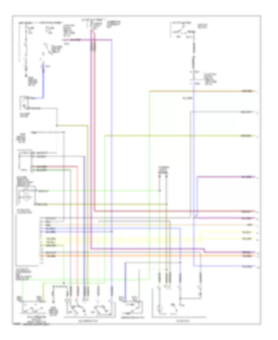
2.0L, Cooling Fan Wiring Diagram, M/T for Dodge Avenger 1997
 https://portal-diagnostov.com/license.html
Automotive Electricians Portal FZCO
Automotive Electricians Portal FZCO
https://portal-diagnostov.com/license.html
https://portal-diagnostov.com/license.html
Automotive Electricians Portal FZCO
Automotive Electricians Portal FZCOList of elements for 2.0L, Cooling Fan Wiring Diagram, M/T for Dodge Avenger 1997:
- (left side of engine compartment)
- Acc
- Automatic compressor ecm (below right side of i/p)
- B-41
- B-63
- Condenser fan motor
- Condenser fan relay (hi) (left front of engine compartment)
- Condenser fan relay (lo) (left front of engine compartment)
- Dual pressure switch
- Engine coolant temperature sensor (right side of engine)
- Fuse 8 20a
- Fusible link 6 30a
- G101 (right front fender)
- Hot at all times
- Ignition switch
- J/c 3
- J/c 4
- Junction block (below left side of i/p)
- Lock
- Powertrain control module
- Radiator fan motor
- Radiator fan relay (hi) (left front of engine compartment)
- Radiator fan relay (lo) (left front of engine compartment)
- Run
- Start
- Underhood fuse/relay box
- Underhood fuse/relay box
- Vehicle speed sensor (on side of trans- axle)
2.5L
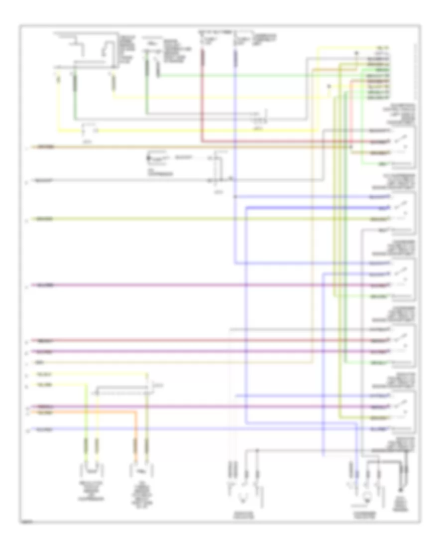
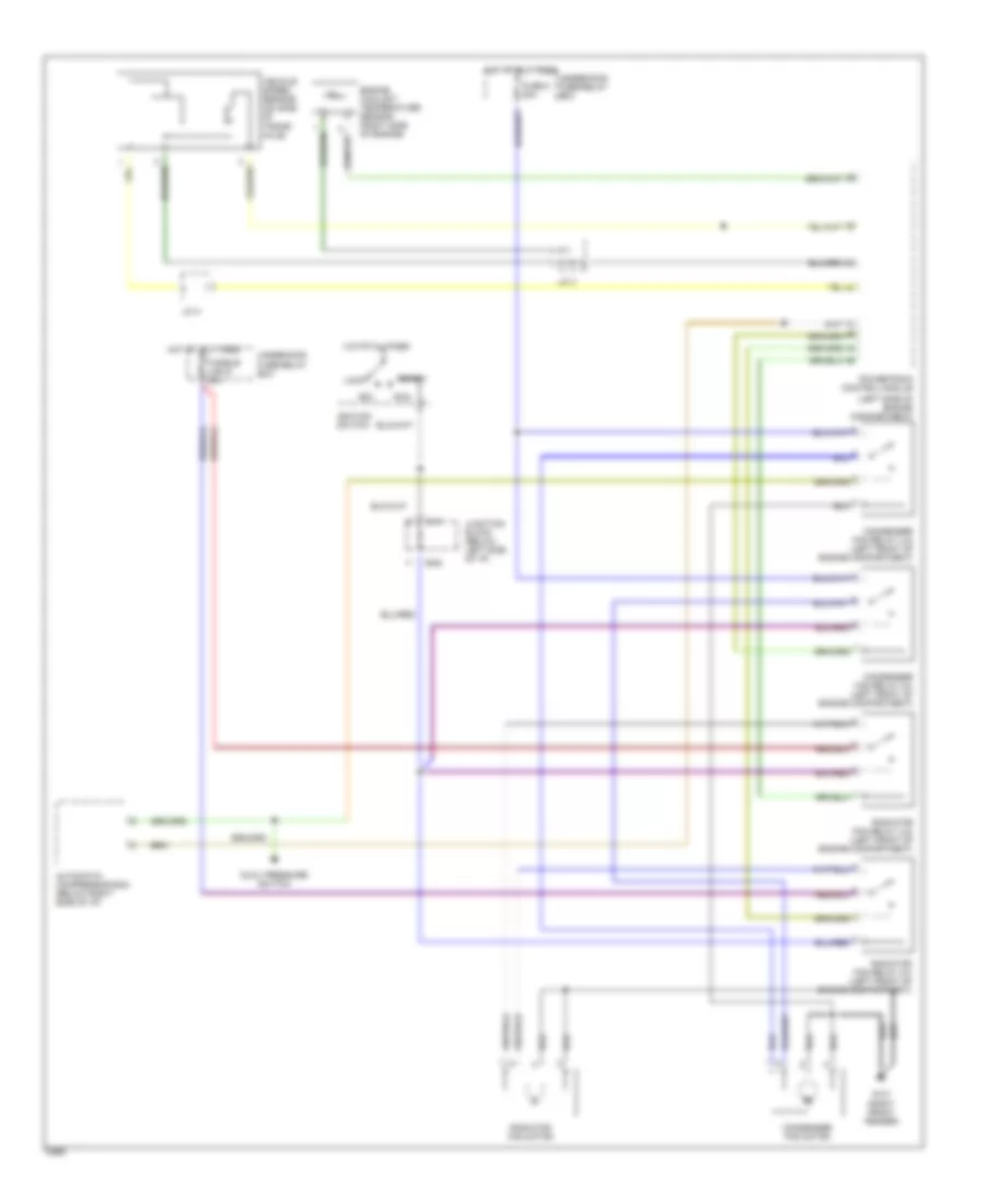
2.5L, Cooling Fan Wiring Diagram for Dodge Avenger 1997
 https://portal-diagnostov.com/license.html
Automotive Electricians Portal FZCO
Automotive Electricians Portal FZCO
https://portal-diagnostov.com/license.html
https://portal-diagnostov.com/license.html
Automotive Electricians Portal FZCO
Automotive Electricians Portal FZCOList of elements for 2.5L, Cooling Fan Wiring Diagram for Dodge Avenger 1997:
- (below right side of i/p)
- Acc
- Automatic compressor ecm
- B-41
- B-63
- Condenser fan motor
- Condenser fan relay (hi) (left front of engine compartment)
- Condenser fan relay (lo) (left front of engine compartment)
- Dual pressure switch
- Eatx ecm (left side of engine compartment)
- Engine coolant temperature sensor (left side of engine)
- Fuse 8 20a
- Fusible link 6 30a
- G101 (right front fender)
- Hot at all times
- Ignition switch
- Input speed sensor (left side of engine)
- J/c 3
- J/c 4
- Junction block (below left side of i/p)
- Lock
- Output speed sensor (left side of engine)
- Powertrain control module (left side of engine compartment)
- Radiator fan motor
- Radiator fan relay (hi1) (left front of engine compartment)
- Radiator fan relay (hi2) (left front of engine compartment)
- Radiator fan relay (lo) (left front of engine compartment)
- Run
- Start
- Underhood fuse/relay box
CRUISE CONTROL
Cruise Control Wiring Diagram for Dodge Avenger 1997
 https://portal-diagnostov.com/license.html
Automotive Electricians Portal FZCO
Automotive Electricians Portal FZCO
https://portal-diagnostov.com/license.html
https://portal-diagnostov.com/license.html
Automotive Electricians Portal FZCO
Automotive Electricians Portal FZCOList of elements for Cruise Control Wiring Diagram for Dodge Avenger 1997:
- (a/t)
- (center of i/p)
- (front of
- (left
- (left side
- A-77
- A-78
- A/t
- Acc
- Accel/ resume
- Auto- cruise control relay (right side of safety wall)
- Auto-cruise control main switch
- Auto-cruise control switch
- Auto-cruise servo (right side of safety wall)
- B-41
- B-54
- B-63
- C-06
- Cancel
- Clock spring
- Coast/ set
- Cruise indic.
- Data link connector b-30
- Eatx control module (a/t) (below center console)
- Fuse 1 20a
- Fuse 3 40a
- Fuse 4 15a
- Fuse 8 10a
- Fuse box (engine compt. relay box)
- Fusible link box (engine compt. relay box)
- G100 left front fender)
- G116 of safety wall)
- G202 side of i/p)
- Hot at all times
- Hot in acc,
- Hot in park
- Ignition switch
- Illum.
- Indic.
- Input speed sensor (left front of trans.)
- Instrument cluster
- J/c 1 (left kick panel)
- J/c 2 (left side of i/p)
- J/c 3 (engine compt. relay box)
- J/c 4 (engine compt. relay box)
- Junction block (left kick panel)
- Lock
- M/t
- Off
- Output speed sensor (left front of trans.)
- Power distribution system
- Powertrain control module (front of left front fender)
- Red
- Run or start
- Start
- Stop lamp switch (on brake pedal)
- To interior lights system
- Transaxle range sensor (on left side of transmission)
- Vehicle speed sensor (dohc m/t) (left front of trans.)
DEFOGGERS
Defogger Wiring Diagram for Dodge Avenger 1997
 https://portal-diagnostov.com/license.html
Automotive Electricians Portal FZCO
Automotive Electricians Portal FZCO
https://portal-diagnostov.com/license.html
https://portal-diagnostov.com/license.html
Automotive Electricians Portal FZCO
Automotive Electricians Portal FZCOList of elements for Defogger Wiring Diagram for Dodge Avenger 1997:
- (left side of i/p)
- (w/o anti-theft)
- 10a
- 30a
- All times
- B-39
- B-40
- B-41
- B-43
- B-54
- B-57
- Data link connector (below left side of i/p)
- Defogger
- Defogger relay
- Defogger switch
- Door mirror (left side)
- Door mirror (right side)
- Door mirror heater relay (right side of i/p)
- Etacs-ecu
- Fuse 13
- Fuse 6
- Fuse 8
- G202
- G202 (left side of i/p)
- Hot at
- Hot in
- Hot in run
- Illumination
- Ind
- Instrument cluster system
- Interior lights system
- Interior relay box (left side of i/p)
- J/b (below left side of i/p)
- J/c 2 (left side of i/p)
- Junction block (below left side of i/p)
- Mirror heater
- Nca
- Or start
- Run
ENGINE PERFORMANCE
2.0L
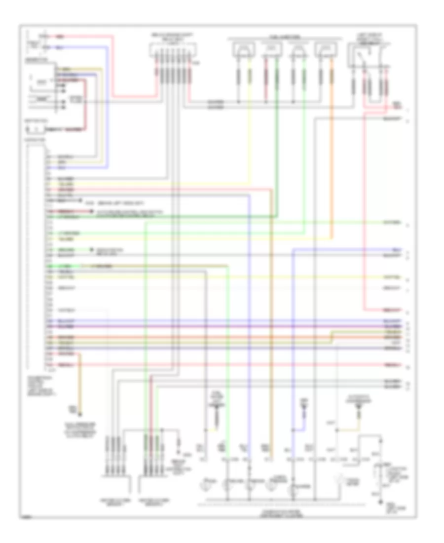
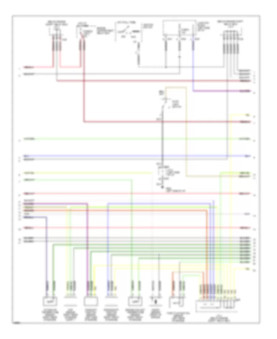
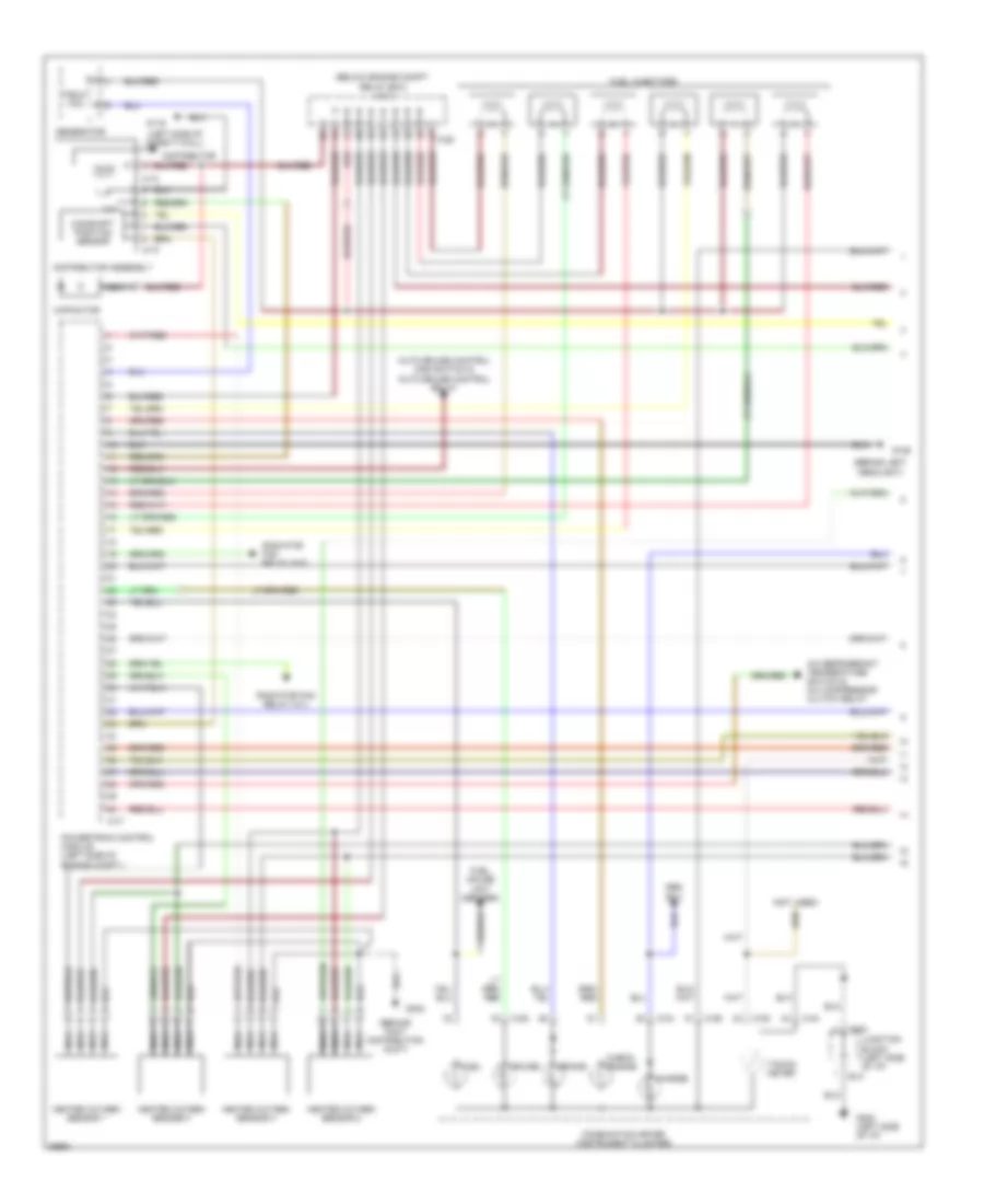
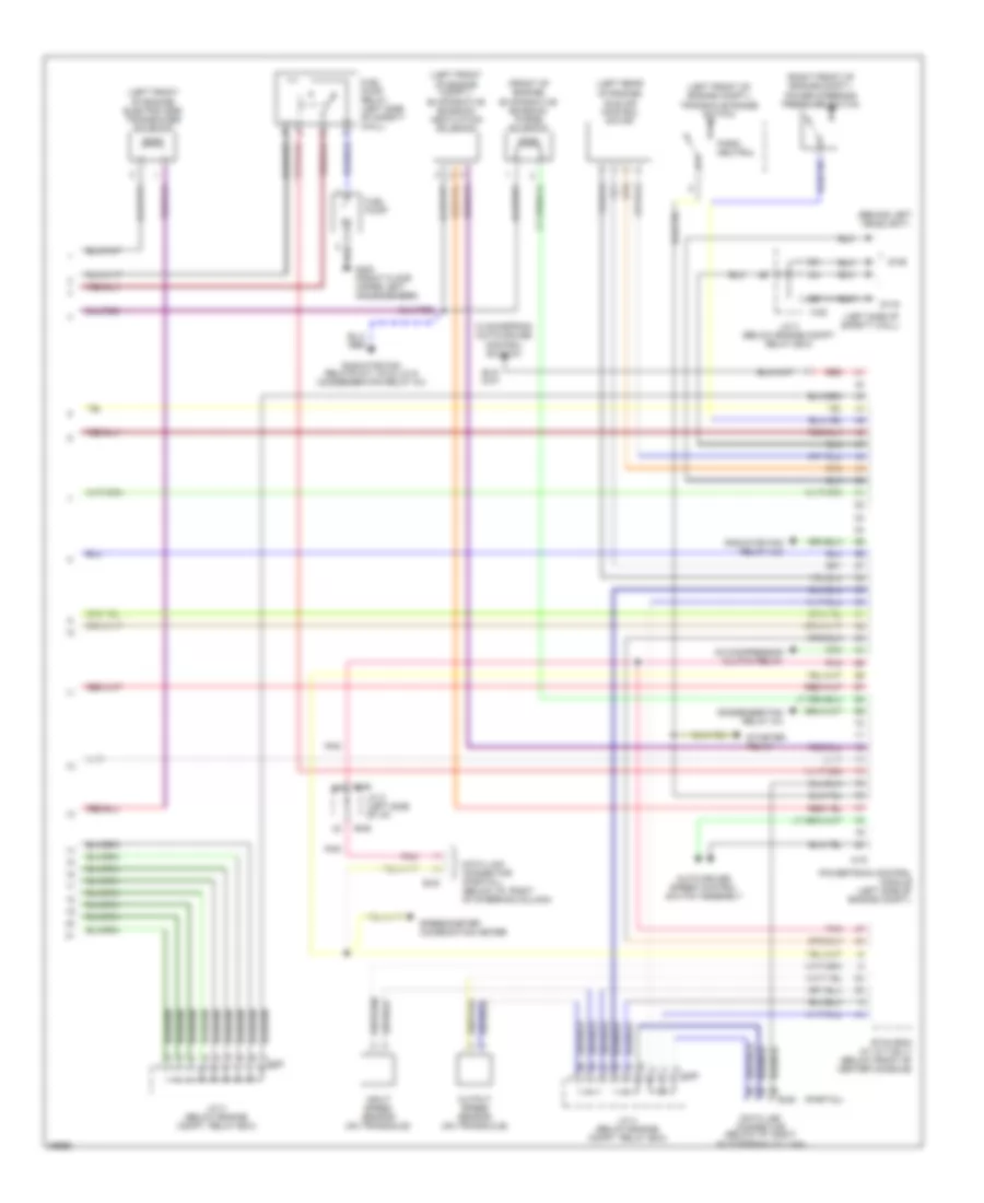
2.0L, Engine Performance Wiring Diagrams (1 of 3) for Dodge Avenger 1997
 https://portal-diagnostov.com/license.html
Automotive Electricians Portal FZCO
Automotive Electricians Portal FZCO
https://portal-diagnostov.com/license.html
https://portal-diagnostov.com/license.html
Automotive Electricians Portal FZCO
Automotive Electricians Portal FZCOList of elements for 2.0L, Engine Performance Wiring Diagrams (1 of 3) for Dodge Avenger 1997:
- (behind foot distribution duct)
- (behind left headlight)
- (below engine compt. relay box) j/c 3
- (left side of safety wall) asd relay
- A-28
- A-77
- Abs- ecu
- Auto-cruise control main switch & auto-cruise control relay
- Automatic compressor- ecm
- B-41
- B-54
- Brake
- C-04
- C-05
- C-06
- Capacitor
- Charge
- Check engine
- Combination meter (instrument cluster)
- Cruise
- Dual pressure switch (a/c) & a/c compressor clutch relay
- Field coil
- Fuel
- Fuel gauge unit (sender)
- Fuel injectors
- G106
- G202 (left side of i/p)
- G302
- Generator
- Heated oxygen sensor 1
- Heated oxygen sensor 2
- Ignition coil
- Junction block (left side of i/p)
- Nca
- Powertrain control module (left side of engine compt.)
- Radiator fan relay (hi2)
- Red
- Spark plugs
- Tacho- meter
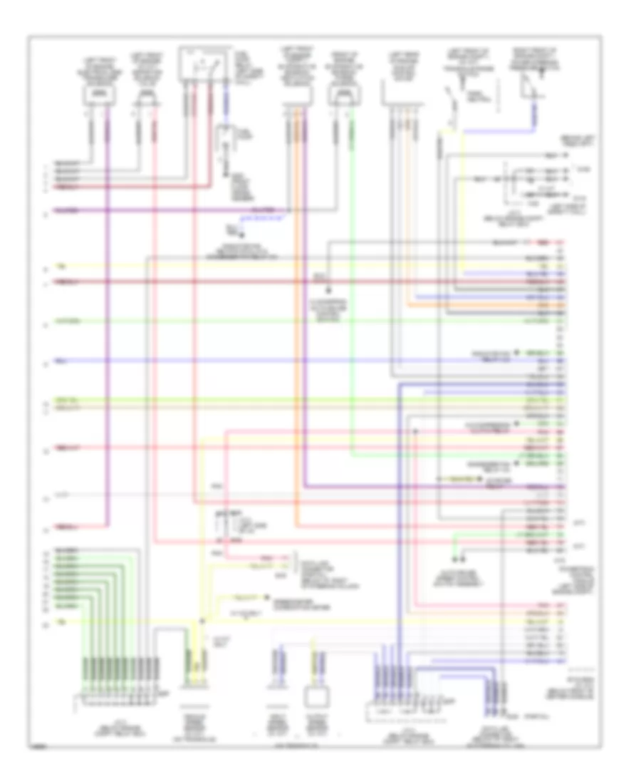
2.0L, Engine Performance Wiring Diagrams (2 of 3) for Dodge Avenger 1997
 https://portal-diagnostov.com/license.html
Automotive Electricians Portal FZCO
Automotive Electricians Portal FZCO
https://portal-diagnostov.com/license.html
https://portal-diagnostov.com/license.html
Automotive Electricians Portal FZCO
Automotive Electricians Portal FZCOList of elements for 2.0L, Engine Performance Wiring Diagrams (2 of 3) for Dodge Avenger 1997:
- (below engine compt. relay box) j/c 3
- (below engine compt. relay box) j/c 4
- A-28
- A-29
- Acc
- B-06
- B-41
- B-54
- B-63
- Camshaft position sensor (left side of engine)
- Crankshaft position sensor (right front of engine)
- Engine compartment relay box
- Engine coolant temperature sensor (right front of engine)
- Fuse 8 10a
- Fusible link 3 30a
- G202 (left side of i/p)
- Hot at all times
- Ig1 nca
- Ignition switch
- Intake air temperature sensor (right rear of engine)
- J/c 2 (left side of i/p)
- J/c 4 (below engine compt. relay box)
- Junction block (left side of i/p)
- Knock sensor (front of engine)
- Lock
- Map sensor (right rear of engine compt.)
- Run
- Start
- Stop light switch
- Throttle position sensor (left rear of engine)
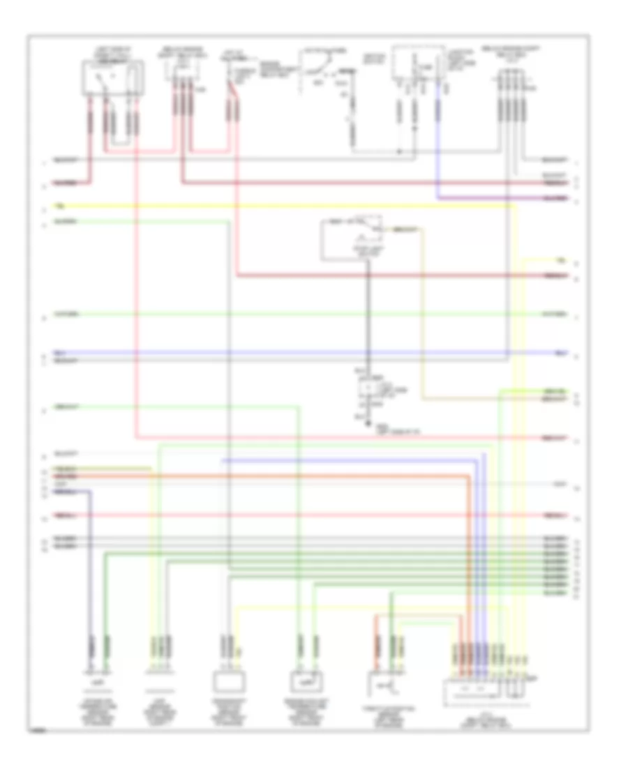
2.0L, Engine Performance Wiring Diagrams (3 of 3) for Dodge Avenger 1997
 https://portal-diagnostov.com/license.html
Automotive Electricians Portal FZCO
Automotive Electricians Portal FZCO
https://portal-diagnostov.com/license.html
https://portal-diagnostov.com/license.html
Automotive Electricians Portal FZCO
Automotive Electricians Portal FZCOList of elements for 2.0L, Engine Performance Wiring Diagrams (3 of 3) for Dodge Avenger 1997:
- (a/t)
- (behind left headlight)
- (front of engine) evaporative emission purge solenoid
- (left front of engine compt.) (w/ a/t)
- (left front of engine compt.) evaporative emission ventilation solenoid
- (left front of engine) (w/ m/t) aspirator solenoid valve
- (left front of engine) electrical egr transducer solenoid
- (left rear of engine)
- (left side of safety wall)
- (m/t)
- (on transaxle)
- (partial)
- (right front of engine compt.)
- A-28
- A-29
- A-78
- A/c compressor clutch relay
- Auto-cruise speed control switch assembly
- B-06
- B-29
- B-30
- Clockspring (auto-cruise control switch)
- Condenser fan relay (hi)
- Data link connector (below i/p, right of steering column)
- Data link connector (partial) (below i/p, right of steering column)
- Etax-ecm (w/ a/t) (below front of center console)
- Fuel pump
- Fuel pump relay (left side of safety wall)
- G106
- G116
- G300 (front floor cross- member)
- Idle air control motor
- Input speed sensor (w/ a/t)
- J/c 2 (left side of i/p)
- J/c 3 (below engine compt. relay box)
- J/c 4 (below engine compt. relay box)
- Output speed sensor (w/ a/t)
- Park/ neutral
- Pnk
- Power steering pressure switch
- Powertrain control module (left side of engine compt.)
- Radiator fan relay (lo)
- Radiator fan relays (hi2 & lo) & condenser fan relay (hi)
- Red
- Speedometer (combination meter)
- Starter relay
- Transaxle range switch
- Vehicle speed sensor (w/ m/t) (on transaxle)
- W/ a/t
- W/ a/t only
- W/ m/t only
2.5L
2.5L, Engine Performance Wiring Diagrams (1 of 3) for Dodge Avenger 1997
 https://portal-diagnostov.com/license.html
Automotive Electricians Portal FZCO
Automotive Electricians Portal FZCO
https://portal-diagnostov.com/license.html
https://portal-diagnostov.com/license.html
Automotive Electricians Portal FZCO
Automotive Electricians Portal FZCOList of elements for 2.5L, Engine Performance Wiring Diagrams (1 of 3) for Dodge Avenger 1997:
- (behind foot distribution duct)
- (behind left headlight)
- (below engine compt. relay box) j/c 3
- (left side of safety wall)
- (not used)
- A-28
- A-73
- A-74
- A-77
- A/c refrigerant temperature switch & a/c compressor clutch relay
- Abs- ecu
- Auto-cruise control main switch & auto-cruise control relay
- B-41
- B-54
- Brake
- C-04
- C-05
- C-06
- Camshaft position sensor
- Capacitor
- Charge
- Check engine
- Combination meter (instrument cluster)
- Cruise
- Distributor
- Distributor assembly
- Field coil
- Fuel
- Fuel gauge unit (sender)
- Fuel injectors
- G106
- G116
- G202 (left side of i/p)
- G302
- Generator
- Heated oxygen sensor 1
- Heated oxygen sensor 2
- Heated oxygen sensor 3
- Heated oxygen sensor 4
- Junction block (left side of i/p)
- Nca
- Powertrain control module (left side of engine compt.)
- Radiator fan relay (hi1)
- Radiator fan relay (hi2)
- Red
- Tacho- meter
2.5L, Engine Performance Wiring Diagrams (2 of 3) for Dodge Avenger 1997
 https://portal-diagnostov.com/license.html
Automotive Electricians Portal FZCO
Automotive Electricians Portal FZCO
https://portal-diagnostov.com/license.html
https://portal-diagnostov.com/license.html
Automotive Electricians Portal FZCO
Automotive Electricians Portal FZCOList of elements for 2.5L, Engine Performance Wiring Diagrams (2 of 3) for Dodge Avenger 1997:
- (below engine compt. relay box) j/c 3
- (below engine compt. relay box) j/c 4
- (left side of safety wall) asd relay
- A-28
- A-29
- Acc
- B-06
- B-41
- B-54
- B-63
- Crankshaft position sensor (right front of engine)
- Engine compartment relay box
- Engine coolant temperature sensor (right front of engine)
- Fuse 10a
- Fusible link 3 30a
- G202 (left side of i/p)
- Hot at all times
- Ig1 nca
- Ignition switch
- Intake air temperature sensor (right rear of engine)
- J/c 2 (left side of i/p)
- J/c 4 (below engine compt. relay box)
- Junction block (left side of i/p)
- Lock
- Map sensor (right rear of engine compt.)
- Run
- Start
- Stop light switch
- Throttle position sensor (left rear of engine)
2.5L, Engine Performance Wiring Diagrams (3 of 3) for Dodge Avenger 1997
 https://portal-diagnostov.com/license.html
Automotive Electricians Portal FZCO
Automotive Electricians Portal FZCO
https://portal-diagnostov.com/license.html
https://portal-diagnostov.com/license.html
Automotive Electricians Portal FZCO
Automotive Electricians Portal FZCOList of elements for 2.5L, Engine Performance Wiring Diagrams (3 of 3) for Dodge Avenger 1997:
- (behind left headlight)
- (front of engine) evaporative emission purge solenoid
- (left front of engine compt.)
- (left front of engine compt.) evaporative emission ventilation solenoid
- (left front of engine) electric egr transducer solenoid
- (left rear of engine)
- (left side of safety wall)
- (partial)
- (right front of engine compt.)
- A-28
- A-29
- A-78
- A/c compressor clutch relay
- Auto-cruise speed control switch assembly
- B-06
- B-29
- B-30
- Clockspring (auto-cruise control switch)
- Condenser fan relay (hi)
- Data link connector (below i/p, right of steering column)
- Data link connector (partial) (below i/p, right of steering column)
- Etax-ecm (w/ a/t only) (below front of center console)
- Fuel pump
- Fuel pump relay (left side of safety wall)
- G106
- G116
- G300 (front floor upper left crossmember)
- Idle air control motor
- Input speed sensor (on transaxle)
- J/c 2 (left side of i/p)
- J/c 3 (below engine compt. relay box)
- J/c 4 (below engine compt. relay box)
- Output speed sensor (on transaxle)
- Park/ neutral
- Pnk
- Power steering pressure switch
- Powertrain control module (left side of engine compt.)
- Radiator fan relay (lo)
- Radiator fan relays (hi1, hi2 & lo) & condenser fan relay (hi)
- Red
- Speedometer (combination meter)
- Starter relay
- Transaxle range switch
EXTERIOR LIGHTS
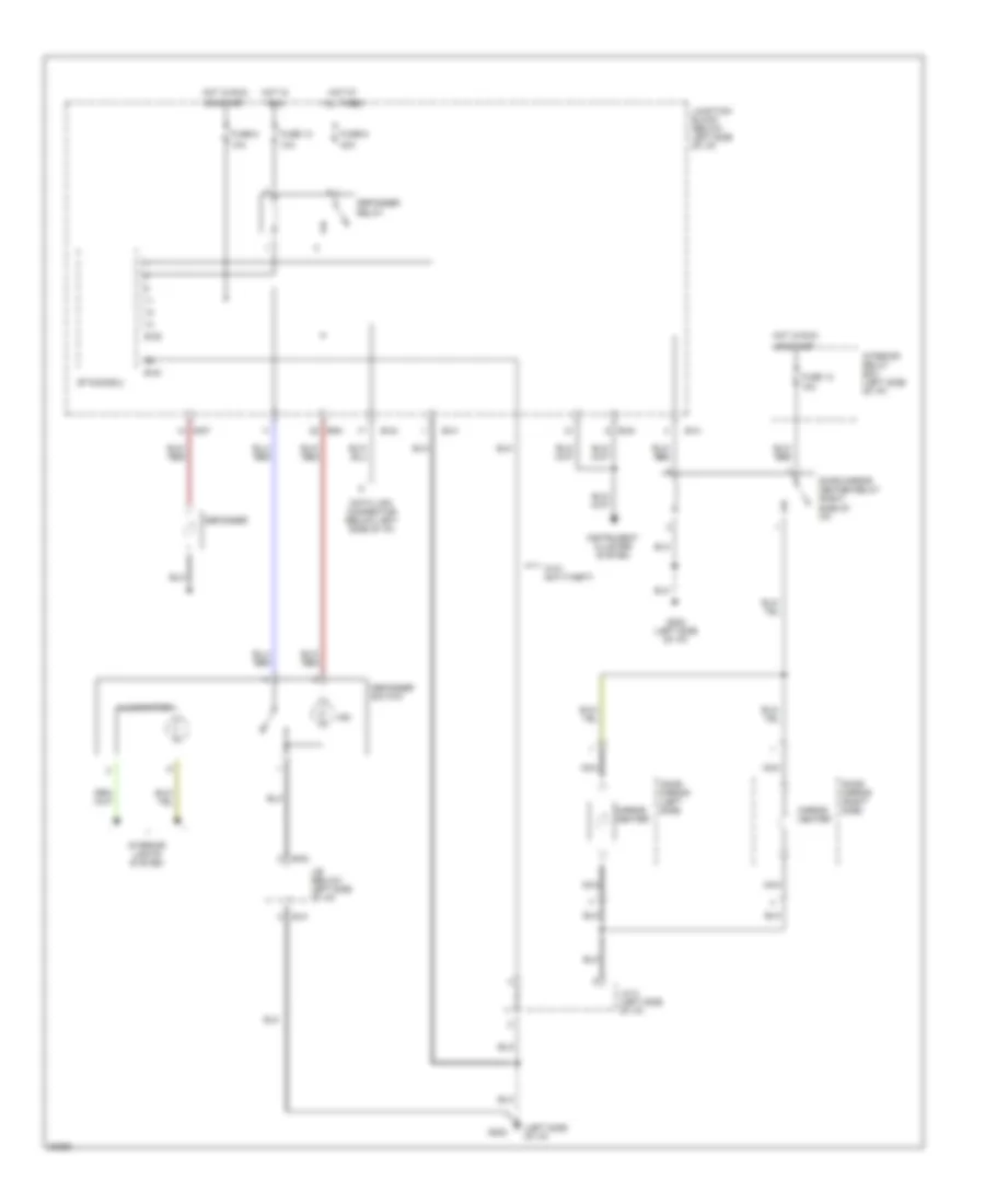
Back-up Lamps Wiring Diagram for Dodge Avenger 1997
 https://portal-diagnostov.com/license.html
Automotive Electricians Portal FZCO
Automotive Electricians Portal FZCO
https://portal-diagnostov.com/license.html
https://portal-diagnostov.com/license.html
Automotive Electricians Portal FZCO
Automotive Electricians Portal FZCOList of elements for Back-up Lamps Wiring Diagram for Dodge Avenger 1997:
- A/t
- Automatic anti-glare inside mirror
- B-43
- B-57
- Back-up light switch (side of transaxle)
- Fuse 10a
- G407 (center rear of trunk)
- Hot in start or run
- J/b
- J/c 1 (left side of i/p)
- Left side back-up light
- M/t
- Right side back-up light
- Sebring only
- Transaxle range sensor (closed in reverse) (side of transaxle)
- Transmissions system
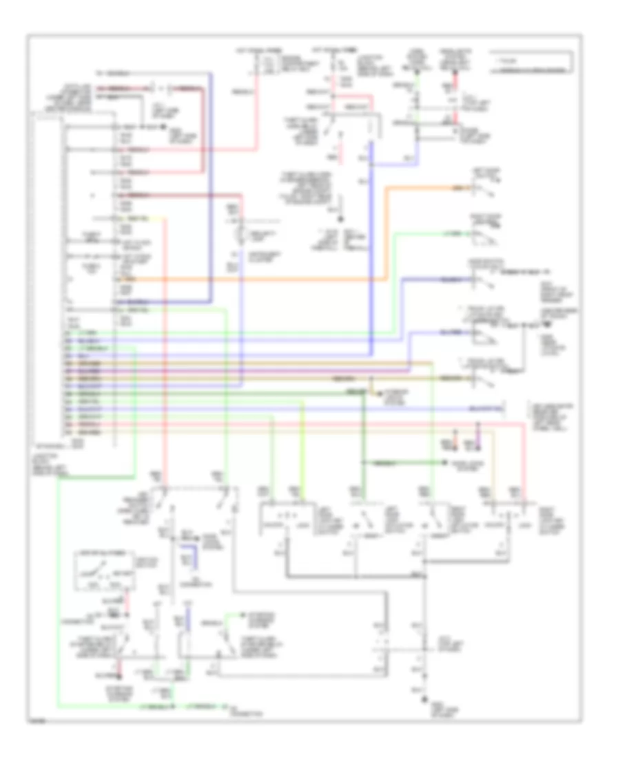
Exterior Lamps Wiring Diagram for Dodge Avenger 1997
 https://portal-diagnostov.com/license.html
Automotive Electricians Portal FZCO
Automotive Electricians Portal FZCO
https://portal-diagnostov.com/license.html
https://portal-diagnostov.com/license.html
Automotive Electricians Portal FZCO
Automotive Electricians Portal FZCOList of elements for Exterior Lamps Wiring Diagram for Dodge Avenger 1997:
- 15a
- 40a
- B-42
- B-43
- B-54
- B-57
- B-63
- Combination meter
- Engine compartment relay box
- Fuse 1 20a
- Fuse 10a
- Fuse 3 15a
- Fuse 4
- Fusible link 4
- G101 (front of right front fender)
- G202 (left side of i/p)
- G300 (below front of driver's seat)
- G407 (center rear of trunk)
- Hazard
- Hazard switch
- Head
- High mounted stop light
- Hot at all times
- Hot in start or run
- Illum
- Interior lights system
- J/b
- J/c 1 (behind left side of i/p)
- J/c 2 (behind left side of i/p)
- Left
- Left side front turn signal light
- Left side license plate light
- Left side position light
- Left side rear combination light
- Left turn ind
- Lighting switch (column switch)
- Nca
- Off
- Red
- Right
- Right side front turn signal light
- Right side license plate light
- Right side position light
- Right side rear combination light
- Right turn ind
- Stop light switch (top of brake pedal bracket)
- Stop/ turn light
- Tail
- Tail light
- Taillight relay (underhood relay box)
- Turn signal and hazard flasher unit (behind center console, on center stay)
- Turn signal switch (column switch)
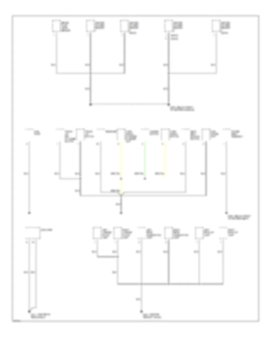
GROUND DISTRIBUTION
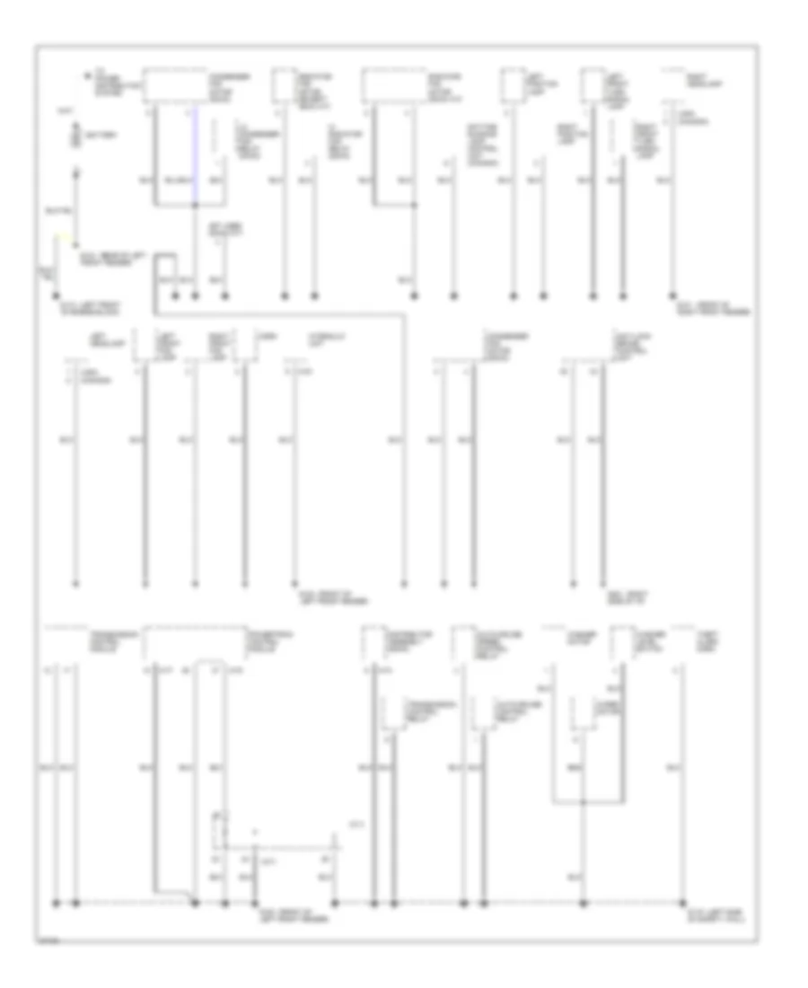
Ground Distribution Wiring Diagram (1 of 3) for Dodge Avenger 1997
 https://portal-diagnostov.com/license.html
Automotive Electricians Portal FZCO
Automotive Electricians Portal FZCO
https://portal-diagnostov.com/license.html
https://portal-diagnostov.com/license.html
Automotive Electricians Portal FZCO
Automotive Electricians Portal FZCOList of elements for Ground Distribution Wiring Diagram (1 of 3) for Dodge Avenger 1997:
- (a/t)
- (canada)
- (front of
- (left front
- (left side
- (rear of left
- (right
- (usa)
- A-33
- A-73
- A-77
- A-78
- Anti-lock brake control unit
- Auto-cruise control relay
- Auto-cruise speed control relay
- Battery
- Condenser fan motor (dohc)
- Condenser fan motor (sohc)
- Daytime running lamp control unit (canada)
- Distributor assembly (sohc)
- G100 left front fender)
- G101 right front fender)
- G104 front fender)
- G110 of engine block)
- G116 of safety wall)
- G201 side of i/p)
- Hi radiator fan relay (sohc)
- Horn
- Hydraulic unit
- J/c 3
- Left front fog lamp
- Left front turn signal lamp
- Left headlamp
- Left position lamp
- Lo condenser fan relay (dohc)
- Not used (dohc m/t)
- Powertrain control module
- Radiator fan motor (dohc a/t)
- Radiator fan motor (except dohc a/t)
- Right front fog lamp
- Right front turn signal lamp
- Right headlamp
- Right position lamp
- Theft alarm horn
- To power distribution system
- Transmission control module
- Transmission control relay
- Washer level switch
- Washer motor
- Wiper motor
Ground Distribution Wiring Diagram (2 of 3) for Dodge Avenger 1997
 https://portal-diagnostov.com/license.html
Automotive Electricians Portal FZCO
Automotive Electricians Portal FZCO
https://portal-diagnostov.com/license.html
https://portal-diagnostov.com/license.html
Automotive Electricians Portal FZCO
Automotive Electricians Portal FZCOList of elements for Ground Distribution Wiring Diagram (2 of 3) for Dodge Avenger 1997:
- (dohc)
- (left
- (sohc)
- A/c switch (sohc)
- Accessory box illumination light
- Ashtray illumination light
- Auto- cruise control main switch
- Auto-cruise control control switch
- Automatic auto-glare inside rear view mirror
- Automatic compressor control module
- B-09
- B-10
- B-30
- B-39
- B-40
- B-41
- B-54
- Blower switch
- C-04
- C-05
- C-06
- Cigarette lighter
- Clock spring
- Clutch pedal position switch (m/t)
- Data link connector
- Defogger switch
- Dome lamp
- Door lock key cylinder switch
- Etacs control unit (j/b)
- Etacs control unit (j/b) (w/o anti- theft)
- G202 side of i/p)
- Headlamp dimmer switch
- Headlamp switch
- Illumination module
- Instrument cluster
- J/b
- J/c 2
- Key reminder switch
- Left door lock actuator
- Left door lock switch
- Left door mirror
- Power door lock relay no. 1 (w/o rke)
- Power window main switch
- Remote controlled mirror switch
- Resistor
- Rheostat
- Right door lock actuator
- Right door lock switch
- Right door mirror
- Stop lamp switch
- Sunroof control unit
- Sunroof switch
- Theft alarm starter relay (w/ anti- theft)
- Turn signal & hazard flasher unit (sebring)
- Wiper/ washer switch
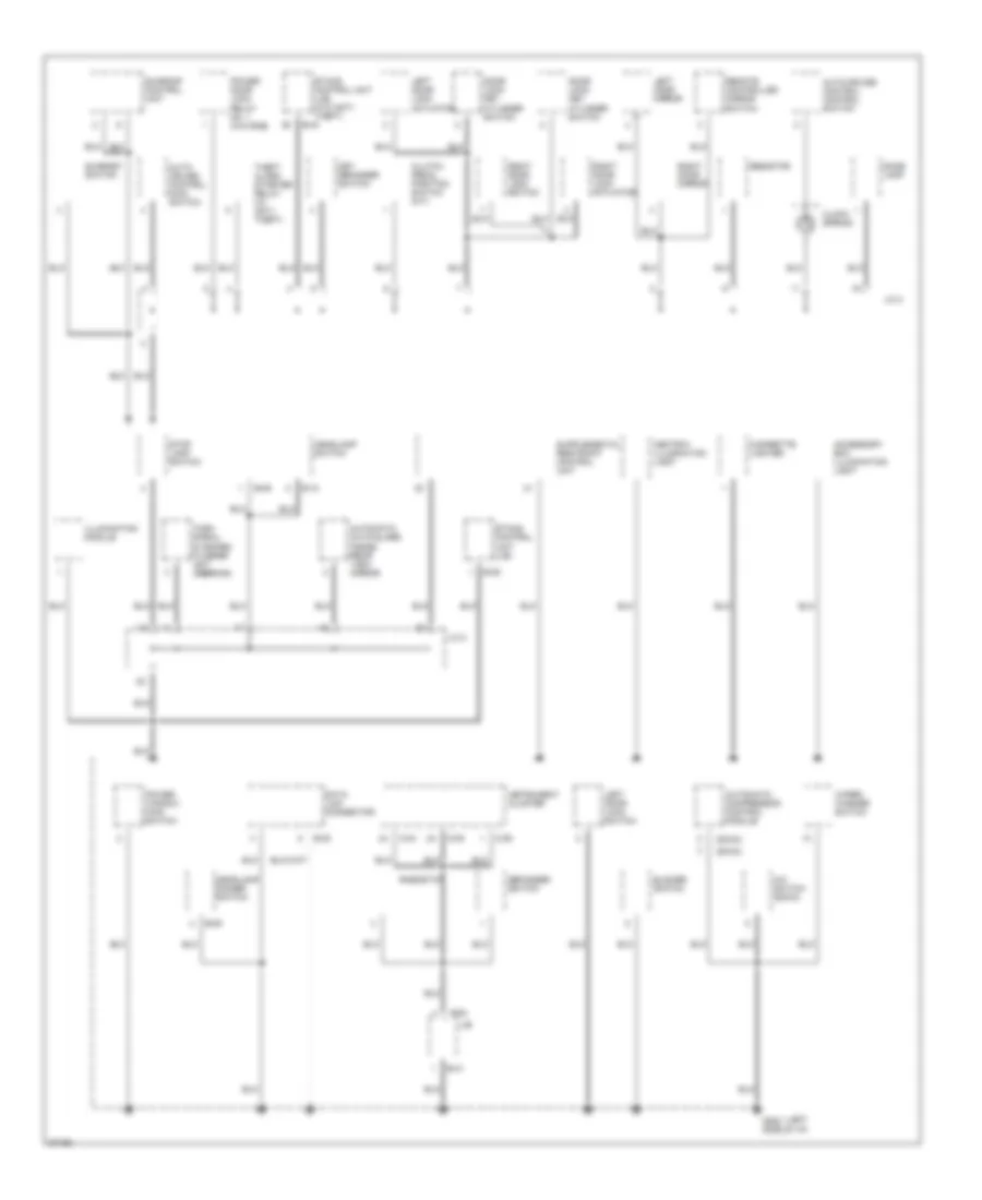
Ground Distribution Wiring Diagram (3 of 3) for Dodge Avenger 1997
 https://portal-diagnostov.com/license.html
Automotive Electricians Portal FZCO
Automotive Electricians Portal FZCO
https://portal-diagnostov.com/license.html
https://portal-diagnostov.com/license.html
Automotive Electricians Portal FZCO
Automotive Electricians Portal FZCOList of elements for Ground Distribution Wiring Diagram (3 of 3) for Dodge Avenger 1997:
- (below front
- (center
- (center of
- (dohc)
- (sohc)
- Amplifier
- Brake fluid level sensor
- Fuel gauge unit
- Fuel pump
- G300 of driver's seat)
- G302 of center console)
- G311 rear shelf)
- G407 rear of trunk)
- Hazard switch
- Heated oxygen sensor
- Heated oxygen sensor (sohc)
- Left back-up lamp
- Left license plate lamp
- Left rear combination lamp
- Power seat assembly
- Receiver
- Right back-up lamp
- Right license plate lamp
- Right rear combination lamp
- Seat belt buckle switch
- Trunk lid key cylinder switch
- Trunk lid switch
- Turn signal & hazard flasher unit
- Turn signal switch
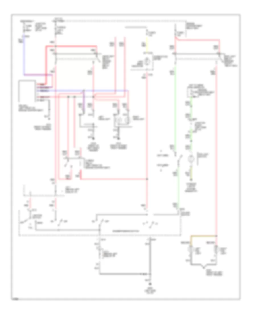
HEADLIGHTS
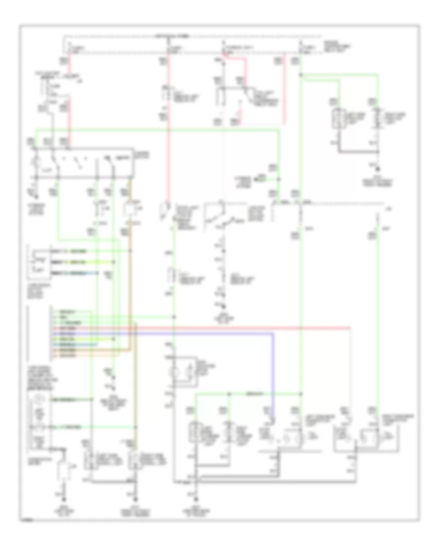
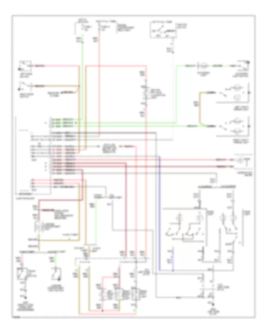
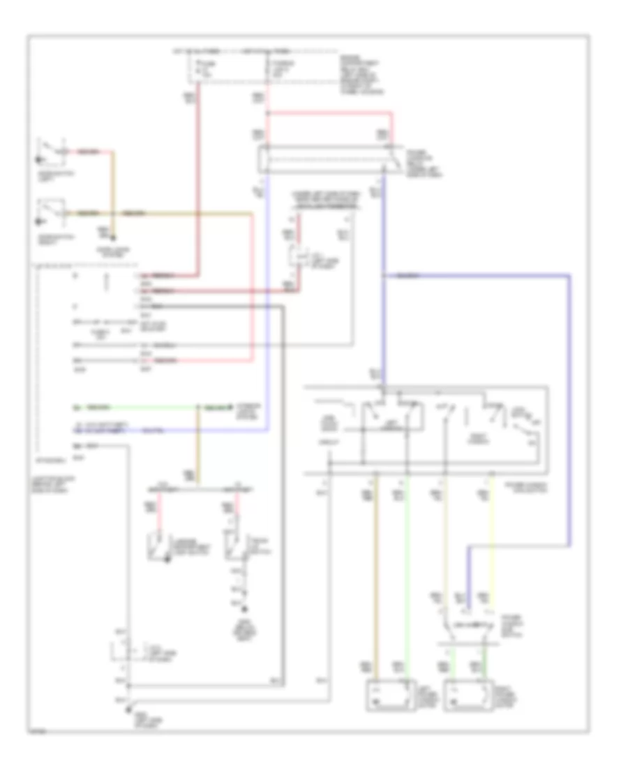
Headlamps/Fog Lamps Wiring Diagram, with DRL for Dodge Avenger 1997
 https://portal-diagnostov.com/license.html
Automotive Electricians Portal FZCO
Automotive Electricians Portal FZCO
https://portal-diagnostov.com/license.html
https://portal-diagnostov.com/license.html
Automotive Electricians Portal FZCO
Automotive Electricians Portal FZCOList of elements for Headlamps/Fog Lamps Wiring Diagram, with DRL for Dodge Avenger 1997:
- (not used)
- 10a
- 15a
- B-09
- B-10
- B-54
- B-63
- C-05
- Column switch
- Combination meter
- Dimmer/passing switch
- Drl-ecu (left front of engine compartment)
- Engine compartment relay box
- Fog light relay (engine compt relay box)
- Fog light switch
- Fuse 10a
- Fuse 15a
- Fuse 5
- Fuse 6
- Fusible
- G100 (front of left front fender)
- G101 (front of right front fender)
- G202 (left side of i/p)
- Head
- Headlight relay (engine compt relay box)
- Hi beam relay (left front of engine compartment)
- High beam indicator
- Hot at all times
- Hot in run
- Hot w/ head/ tail lights on
- Interior lights system (rheostat)
- J/c 1 (behind left side of i/p)
- J/c 2 (behind left side of i/p)
- Junction block (left side of i/p)
- Left fog light
- Left headlight
- Lighting switch
- Link 4 40a
- Nca
- Off
- Red
- Right fog light
- Right headlight
- Tail
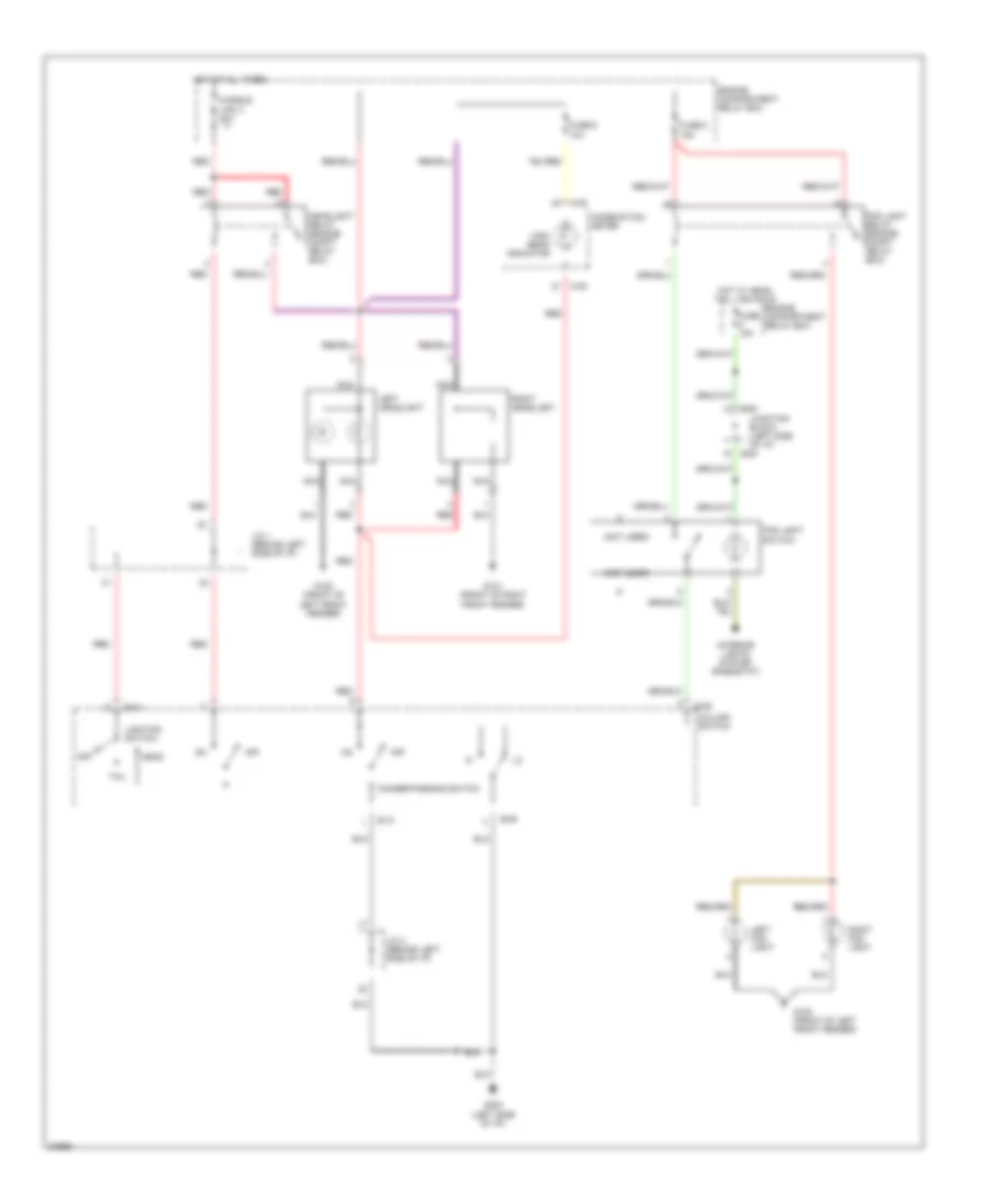
Headlamps/Fog Lamps Wiring Diagram, without DRL for Dodge Avenger 1997
 https://portal-diagnostov.com/license.html
Automotive Electricians Portal FZCO
Automotive Electricians Portal FZCO
https://portal-diagnostov.com/license.html
https://portal-diagnostov.com/license.html
Automotive Electricians Portal FZCO
Automotive Electricians Portal FZCOList of elements for Headlamps/Fog Lamps Wiring Diagram, without DRL for Dodge Avenger 1997:
- (not used)
- 10a
- 15a
- B-09
- B-10
- B-54
- B-63
- C-05
- Column switch
- Combination meter
- Dimmer/passing switch
- Engine compartment relay box
- Fog light relay (engine compt relay box)
- Fog light switch
- Fuse 15a
- Fuse 5
- Fuse 6
- Fusible
- G100 (front of left front fender)
- G101 (front of right front fender)
- G202 (left side of i/p)
- Head
- Headlight relay (engine compt relay box)
- High beam indicator
- Hot at all times
- Hot w/ head/ tail lights on
- Interior lights system (rheostat)
- J/c 1 (behind left side of i/p)
- J/c 2 (behind left side of i/p)
- Junction block (left side of i/p)
- Left fog light
- Left headlight
- Lighting switch
- Link 4 40a
- Nca
- Off
- Red
- Right fog light
- Right headlight
- Tail
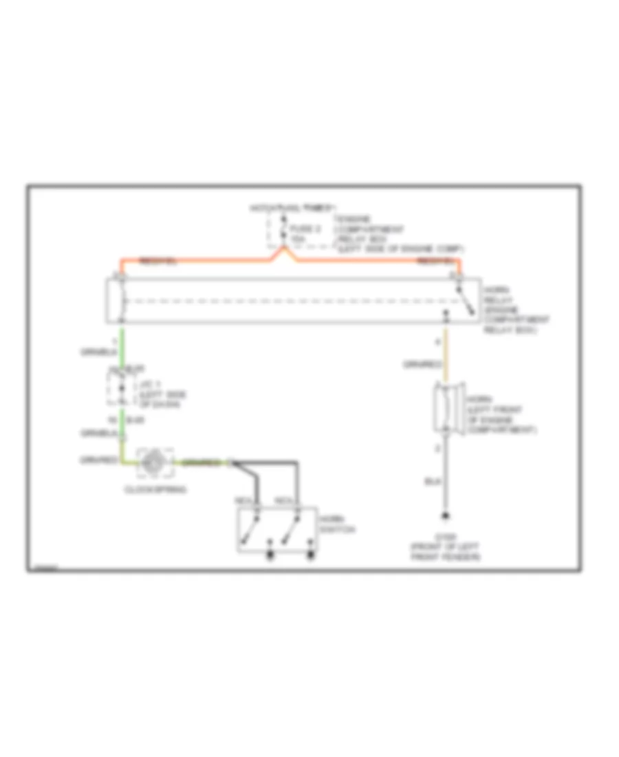
HORN
Horn Wiring Diagram for Dodge Avenger 1997
 https://portal-diagnostov.com/license.html
Automotive Electricians Portal FZCO
Automotive Electricians Portal FZCO
https://portal-diagnostov.com/license.html
https://portal-diagnostov.com/license.html
Automotive Electricians Portal FZCO
Automotive Electricians Portal FZCOList of elements for Horn Wiring Diagram for Dodge Avenger 1997:
- B-05
- Clockspring
- Engine compartment relay box (left side of engine comp)
- Fuse 2 15a
- G100 (front of left front fender)
- Horn (left front of engine compartment)
- Horn relay (engine compartment relay box)
- Horn switch
- Hot at all times
- J/c 1 (left side of dash)
- Nca
INSTRUMENT CLUSTER
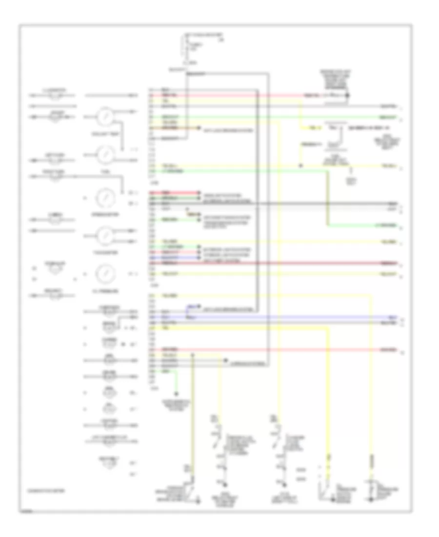
Instrument Cluster Wiring Diagram (1 of 2) for Dodge Avenger 1997
 https://portal-diagnostov.com/license.html
Automotive Electricians Portal FZCO
Automotive Electricians Portal FZCO
https://portal-diagnostov.com/license.html
https://portal-diagnostov.com/license.html
Automotive Electricians Portal FZCO
Automotive Electricians Portal FZCOList of elements for Instrument Cluster Wiring Diagram (1 of 2) for Dodge Avenger 1997:
- 10a
- Abs
- Air conditioning system
- Anti-lock brakes system
- Anti-theft system
- B-54
- Brake
- Brake fluid level switch (on brake master cylinder)
- C-04
- C-05
- C-06
- Charge
- Check eng
- Combination meter
- Coolant temp
- Cruise
- Dohc
- Dohc only
- Door ajar
- Engine coolant temperature gauge unit (right side of engine)
- Exterior lights system
- Fuel
- Fuel gauge unit (in fuel tank)
- Fuse 8
- G116 (left side of safety wall)
- G300 (below front of driver's seat)
- G302 (below front of center console)
- Headlights system
- Hi beam
- Hot in run or start
- Illumination
- Interior lights system
- J/b
- Left turn
- Low fuel
- Low washer fluid
- Nca
- O/d off
- Oil
- Oil pressure
- Oil pressure gauge unit
- Oil pressure switch (side of engine)
- Parking brake switch (on park brake lever)
- Red
- Right turn
- Seat belt
- Security
- Sohc
- Speedometer
- Srs
- Tachometer
- Transmissions system (o/d switch)
- Warning systems
- Washer fluid level switch
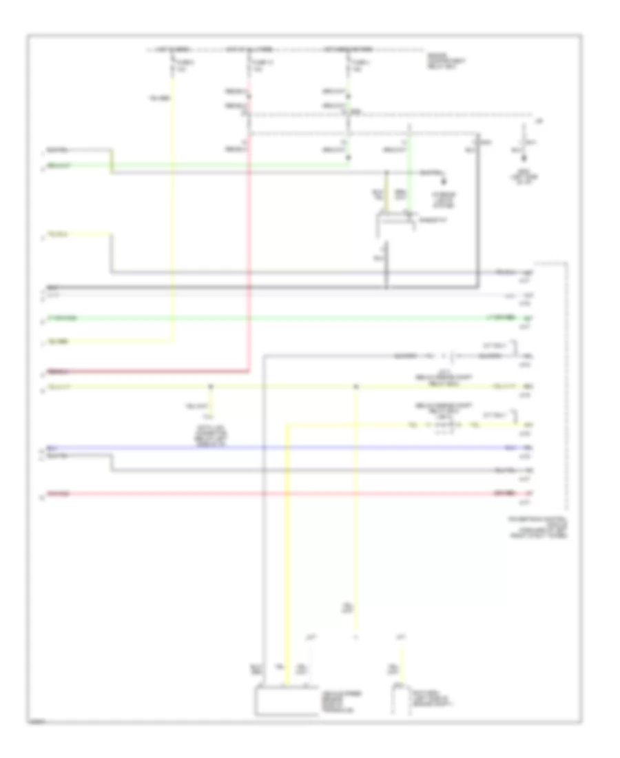
Instrument Cluster Wiring Diagram (2 of 2) for Dodge Avenger 1997
 https://portal-diagnostov.com/license.html
Automotive Electricians Portal FZCO
Automotive Electricians Portal FZCO
https://portal-diagnostov.com/license.html
https://portal-diagnostov.com/license.html
Automotive Electricians Portal FZCO
Automotive Electricians Portal FZCOList of elements for Instrument Cluster Wiring Diagram (2 of 2) for Dodge Avenger 1997:
- (below engine compt relay box) j/c 4
- 10a
- 15a
- A-77
- A-78
- A/t
- B-41
- B-54
- Data link connector (below left side of i/p)
- Eatx-ecm (left side of engine compt.)
- Engine compartment relay box
- Fuse 10
- Fuse 4
- Fuse 6
- G202 (left side of i/p)
- Hot at all times
- Hot head or park
- Hot in head
- Interior lights system
- J/b
- J/c 3 (below engine compt relay box)
- M/t
- M/t only
- Powertrain control module (forward of left front strut tower)
- Rheostat
- Vehicle speed sensor (side of transaxle)
INTERIOR LIGHTS
Courtesy Lamp Wiring Diagram for Dodge Avenger 1997
 https://portal-diagnostov.com/license.html
Automotive Electricians Portal FZCO
Automotive Electricians Portal FZCO
https://portal-diagnostov.com/license.html
https://portal-diagnostov.com/license.html
Automotive Electricians Portal FZCO
Automotive Electricians Portal FZCOList of elements for Courtesy Lamp Wiring Diagram for Dodge Avenger 1997:
- (w/ rke)
- 10a
- 15a
- Acc
- B-39
- B-40
- B-41
- B-42
- B-43
- B-53
- B-54
- B-57
- B-63
- Combination meter
- Data link connector (below left side of i/p)
- Dome light
- Door
- Door locks system (keyless entry receiver)
- Engine compartment relay box
- Etacs ecu
- F8 10a
- Fuse 10
- Fuse 4
- G202 (left side of i/p)
- G300 (front floor, upper left crossmember)
- Glove box light
- Glove box light switch
- Hot at all times
- Hot w/ lights on
- Ignition key hole illumination light
- Ignition switch
- J/c 1 (left side of i/p)
- J/c 2 (left side of i/p)
- Junction block
- Left door switch
- Left front foot light
- Left vanity mirror light
- Luggage compartment light
- Luggage compartment light switch
- Nca
- Off
- Rear foot light
- Reciever
- Red/
- Right door switch
- Right front foot light
- Right vanity mirror light
- Start
- Theft
- Trunk lid switch
- W/ sunroof
- W/anti-
- W/anti- theft
- W/anti-theft
- W/o anti-
- W/o anti-theft
- W/o sunroof
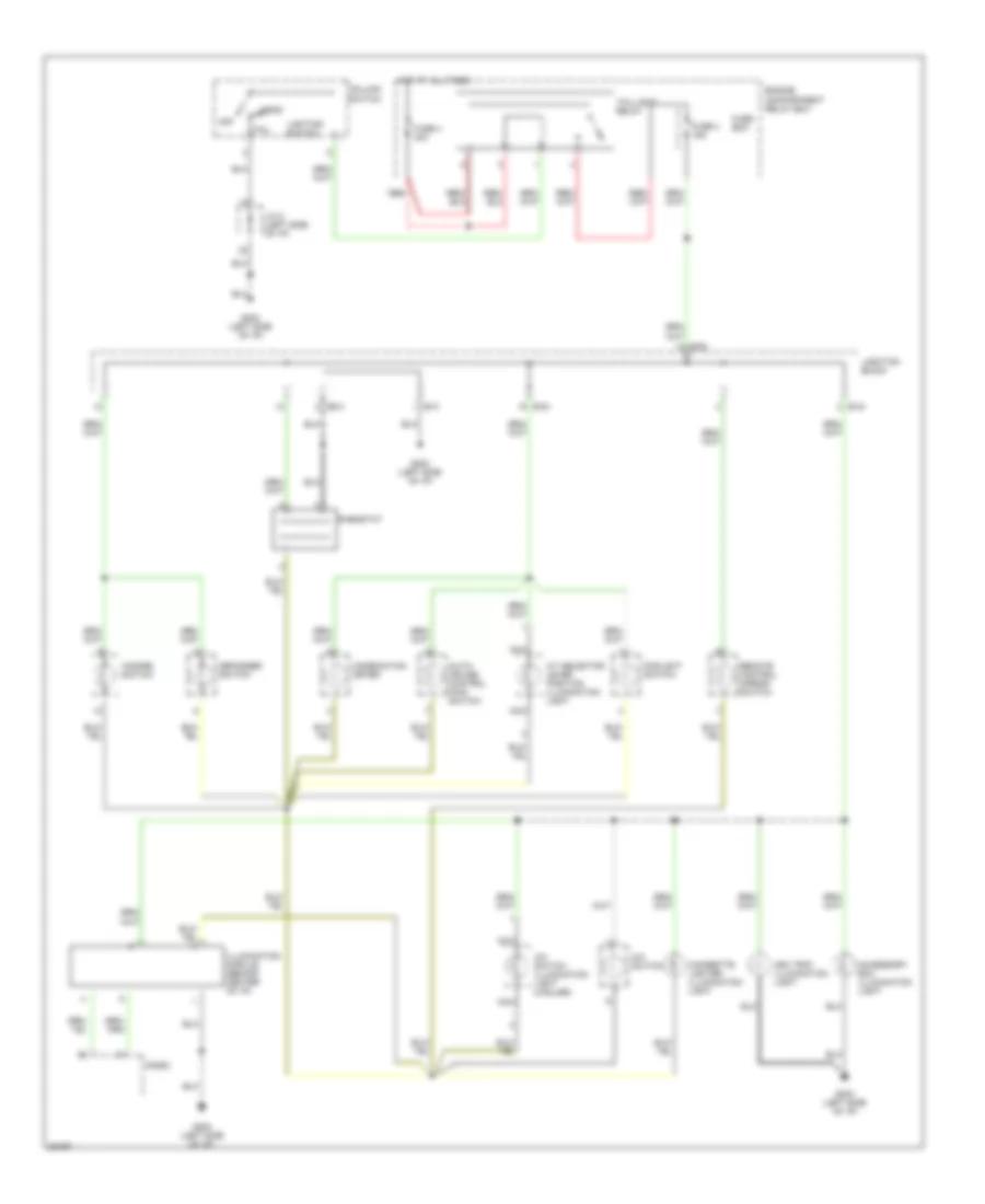
Instrument Illumination Wiring Diagram for Dodge Avenger 1997
 https://portal-diagnostov.com/license.html
Automotive Electricians Portal FZCO
Automotive Electricians Portal FZCO
https://portal-diagnostov.com/license.html
https://portal-diagnostov.com/license.html
Automotive Electricians Portal FZCO
Automotive Electricians Portal FZCOList of elements for Instrument Illumination Wiring Diagram for Dodge Avenger 1997:
- A/c switch
- A/c switch illumination light (2 bulbs)
- A/t selector lever position illumination light
- Accessory box illumination light
- Ash tray illumination light
- Auto- cruise control main switch
- B-41
- B-43
- B-54
- B-63
- Cigarette lighter illumination light
- Column switch
- Combination meter
- Defogger switch
- Engine compartment relay box
- Foglight switch
- Fuse 4 15a
- Fuse 4 40a
- Fuse box
- G202 (left side of i/p)
- Hazard switch
- Head
- Hot at all times
- Illumination module (behind center of i/p)
- J/c 2 (left side of i/p)
- Junction block
- Lighting switch
- Nca
- Off
- Radio
- Red
- Remote control mirror switch
- Rheostat
- Tail
- Taillight relay
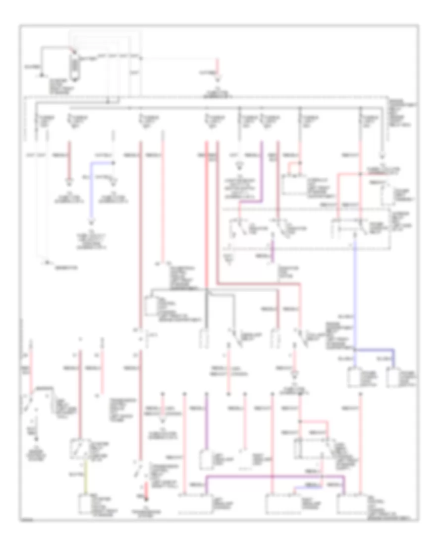
POWER DISTRIBUTION
Power Distribution Wiring Diagram (1 of 4) for Dodge Avenger 1997
 https://portal-diagnostov.com/license.html
Automotive Electricians Portal FZCO
Automotive Electricians Portal FZCO
https://portal-diagnostov.com/license.html
https://portal-diagnostov.com/license.html
Automotive Electricians Portal FZCO
Automotive Electricians Portal FZCOList of elements for Power Distribution Wiring Diagram (1 of 4) for Dodge Avenger 1997:
- A40
- Asd relay (left side of safety wall)
- Battery
- Drl control unit (canada) (left front of engine compartment)
- Engine compartment relay box (engine compt. relay box)
- Engine compartment relay box (left front of engine compartment)
- Fusible link 1 120a
- Fusible link 2 60a
- Fusible link 3 40a
- Fusible link 4 40a
- Fusible link 5 30a
- Fusible link 6 30a
- Fusible link 7 50a
- Fusible link 8 30a
- Generator
- Headlamp relay
- Hi radiator fan
- High beam relay (canada) (left front of engine compt.)
- Hydraulic unit (left front of engine compartment)
- Interior relay box (left side of i/p)
- J/c 4
- Left headlamp (canada)
- Left headlamp (usa)
- Lo radiator fan
- Power seat assembly
- Power window main switch
- Power window sub switch
- Power windows relay
- Powertrain control module (left front of engine compartment)
- Radiator fan motor
- Red
- Red/
- Right headlamp (canada)
- Right headlamp (usa)
- Starter (a/t) motor (right front of engine)
- Starter motor (right front of engine)
- Starter relay (a/t) (center of i/p)
- Taillamp relay
- To engine controls system
- To fuse 1,5,6,10,11 (j/b) cavity 1, conn b-62 (diagram 3 of 4)
- To fuse 10 (f/b) (diagram 2 of 4)
- To fuse 4 (f/b) (diagram 2 of 4)
- To fuse 5 & 6 (f/b) (diagram 2 of 4)
- To fuse 7 (f/b) (diagram 2 of 4)
- To fuse 8 (f/b) (diagram 2 of 4)
- To fuses 1,2 & 3 (f/b) (diagram 2 of 4)
- To junction block cavity 7 & ignition switch cavity 1 (diagram 4 of 4)
- To transmissions system
- Transmission control module (a/t) (left shock tower)
- Transmission control relay (a/t) (left side of safety wall)
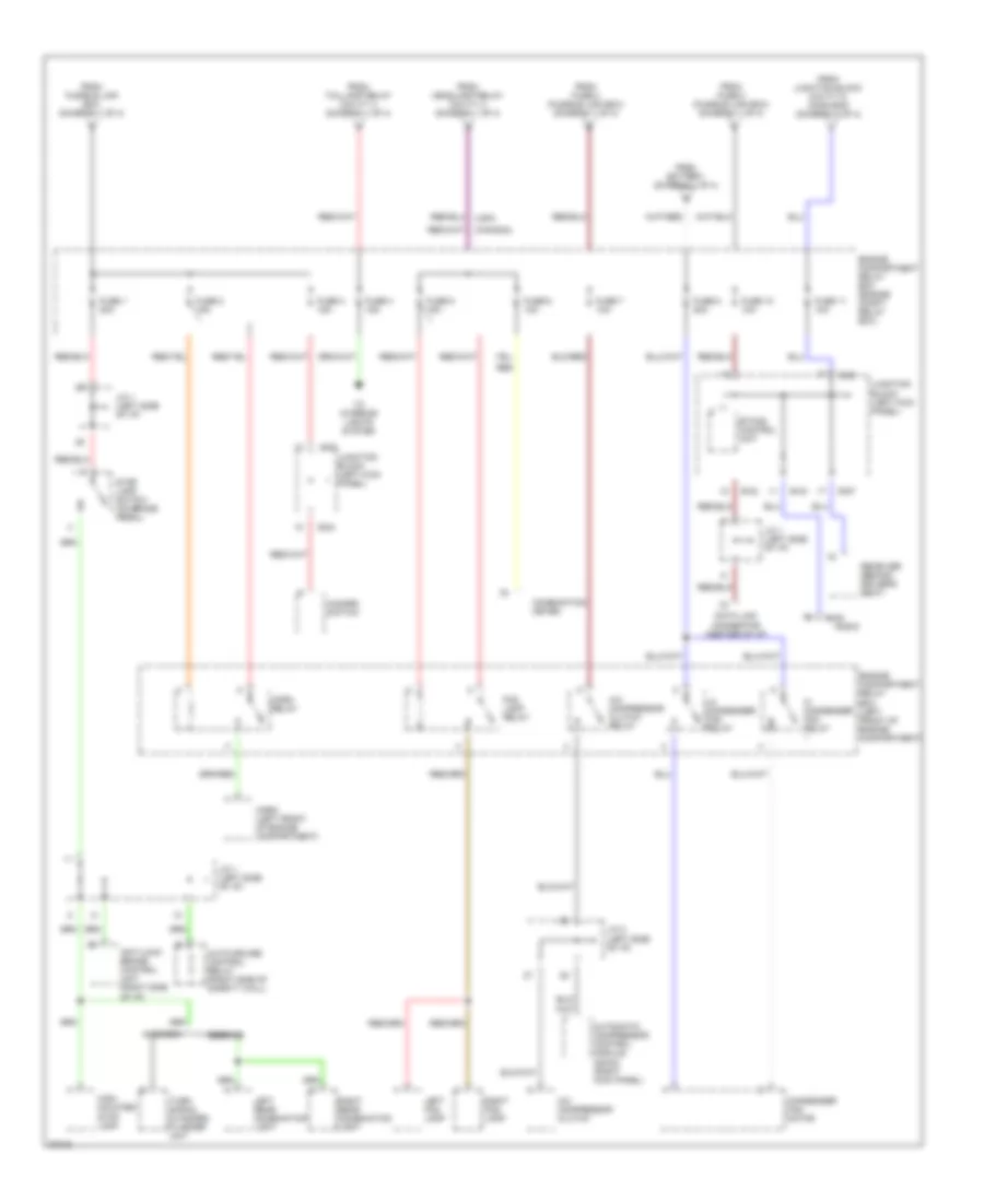
Power Distribution Wiring Diagram (2 of 4) for Dodge Avenger 1997
 https://portal-diagnostov.com/license.html
Automotive Electricians Portal FZCO
Automotive Electricians Portal FZCO
https://portal-diagnostov.com/license.html
https://portal-diagnostov.com/license.html
Automotive Electricians Portal FZCO
Automotive Electricians Portal FZCOList of elements for Power Distribution Wiring Diagram (2 of 4) for Dodge Avenger 1997:
- (canada)
- (usa)
- A/c compressor clutch
- A/c compressor clutch relay
- Anti-lock brake control unit (right side of i/p)
- Auto-cruise control relay (right side of safety wall)
- Automatic compressor control module (dohc) (right kick panel)
- Avenger
- B-42
- B-43
- B-49
- B-54
- B-57
- B-63
- Combination meter
- Condenser fan motor
- Data link connector (center of i/p)
- Engine compartment relay box (engine compt. relay box)
- Engine compartment relay box (left front of engine compartment)
- Etacs control unit
- Fog lamp relay
- From battery (diagram 1 of 4)
- From fuse 2 (fusible link box) (diagram 1 of 4)
- From fusible link box (diagram 1 of 4)
- From headlamp relay cavity 4 (diagram 1 of 4)
- From junction block cavity 5, conn b-63 (diagram 3 of 4)
- From taillamp relay cavity 4 (diagram 1 of 4)
- Fuse 1 20a
- Fuse 10 10a
- Fuse 11 10a
- Fuse 2 15a
- Fuse 3 15a
- Fuse 4 15a
- Fuse 5 15a
- Fuse 6 10a
- Fuse 7 10a
- Fuse 8 20a
- Hazard switch
- Hi condenser fan relay
- High- mounted stop lamp
- Horn (left front of engine compartment)
- Horn relay
- J/c 1 (left side of i/p)
- J/c 2 (left side of i/p)
- Junction block (left kick panel)
- Left fog lamp
- Left rear combination light
- Lo condenser fan relay
- Radio
- Receiver (behind driver's seat)
- Red
- Right fog lamp
- Right rear combination light
- Sebring
- Stop lamp switch (on brake pedal)
- To interior lights system
- Turn signal & hazard flasher unit
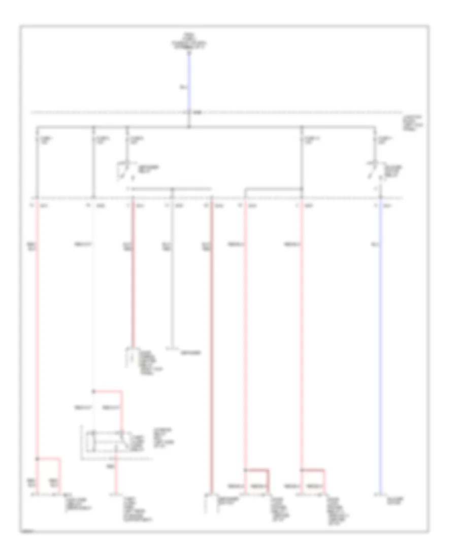
Power Distribution Wiring Diagram (3 of 4) for Dodge Avenger 1997
 https://portal-diagnostov.com/license.html
Automotive Electricians Portal FZCO
Automotive Electricians Portal FZCO
https://portal-diagnostov.com/license.html
https://portal-diagnostov.com/license.html
Automotive Electricians Portal FZCO
Automotive Electricians Portal FZCOList of elements for Power Distribution Wiring Diagram (3 of 4) for Dodge Avenger 1997:
- Amplifier (below rear shelf)
- B-41
- B-42
- B-43
- B-52
- B-57
- B-62
- Blower motor
- Blower motor relay
- Defogger
- Defogger relay
- Defogger switch
- Door lock power relay 1 (center of i/p)
- Door lock power relay 2 (rke only) (center of i/p)
- Door mirror heater relay (right kick panel)
- E-12
- From fuse 2 (fusible link box) (diagram 1 of 4)
- Fuse 1 15a
- Fuse 10 10a
- Fuse 11 30a
- Fuse 5 10a
- Fuse 6 30a
- Interior relay box (left side of i/p)
- Junction block (left kick panel)
- Red
- Red/
- Theft alarm horn (left rear of engine compartment)
- Theft alarm horn relay
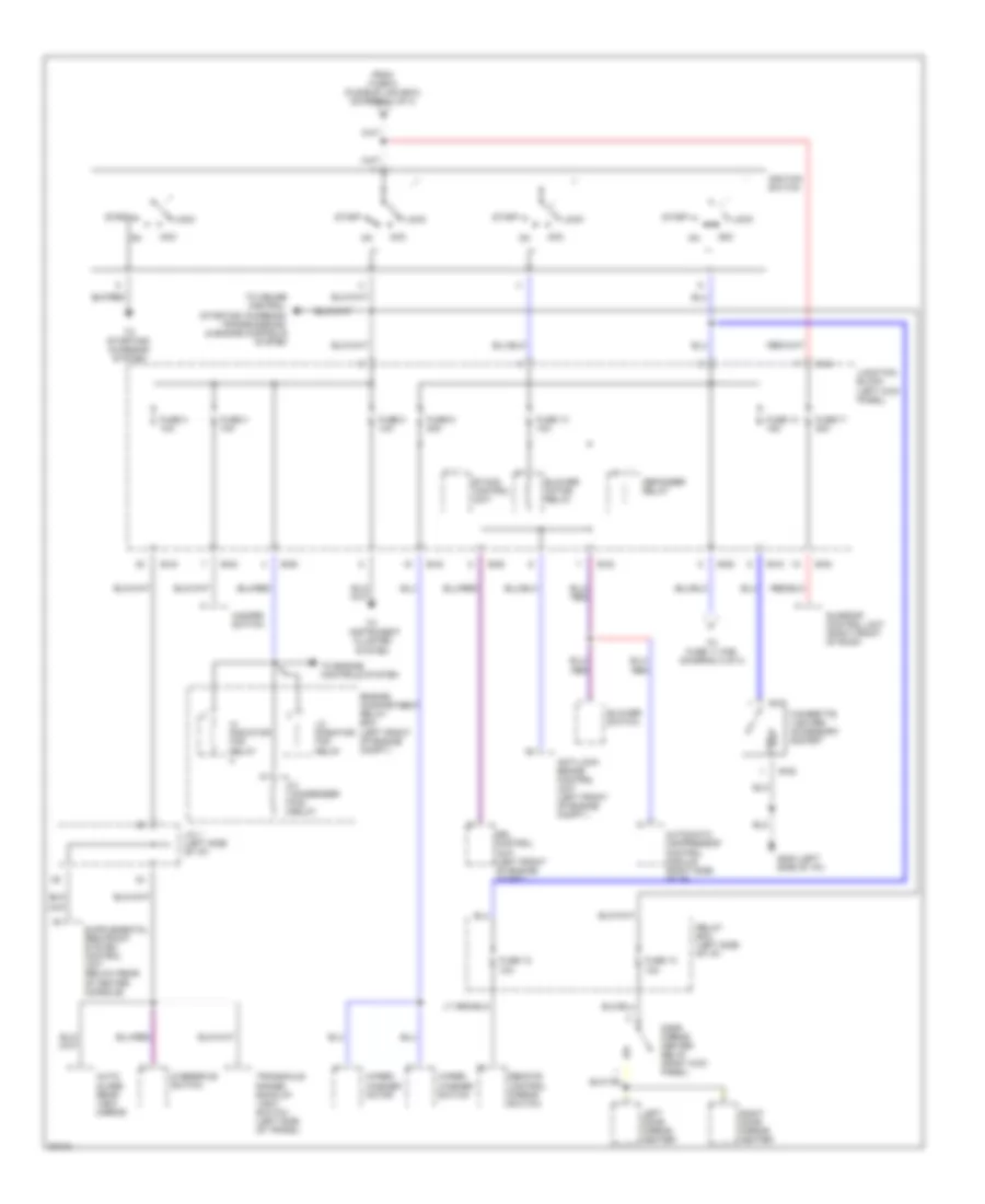
Power Distribution Wiring Diagram (4 of 4) for Dodge Avenger 1997
 https://portal-diagnostov.com/license.html
Automotive Electricians Portal FZCO
Automotive Electricians Portal FZCO
https://portal-diagnostov.com/license.html
https://portal-diagnostov.com/license.html
Automotive Electricians Portal FZCO
Automotive Electricians Portal FZCOList of elements for Power Distribution Wiring Diagram (4 of 4) for Dodge Avenger 1997:
- (left
- Acc
- Anti-lock brake control unit (left front of engine compt.)
- Auto- glare rear view mirror
- Automatic compressor control module (right side of i/p)
- B-27
- B-28
- B-41
- B-42
- B-43
- B-54
- B-63
- Blower motor relay
- Blower switch
- Cigarette lighter/ accessory socket
- Defogger relay
- Door mirror heater relay (right kick panel)
- Drl control unit (left front of engine compt.)
- Engine compartment relay box (left front of engine compt.)
- Etacs control unit
- From fuse 5 (fusible link box) (diagram 1 of 4)
- Fuse 12 10a
- Fuse 13 10a
- Fuse 14 15a
- Fuse 17 20a
- Fuse 3 10a
- Fuse 4 10a
- Fuse 8 10a
- Fuse 9 20a
- G202 side of i/p))
- Hazard switch
- Hi condenser fan relay
- Hi radiator fan relay
- Ignition switch
- J/c 1 (left side of i/p)
- Junction block (left kick panel)
- Left door mirror heater
- Lo radiator fan relay
- Lock
- Overdrive switch
- Red
- Relay box (left side of i/p)
- Remote control mirror switch
- Right door mirror heater
- Start
- Sunroof control unit (right front of roof)
- To cruise control, starting/ charging, transmissions, & engine controls system
- To engine controls system
- To fuse 11 (f/b) (diagram 2 of 4)
- To instrument cluster system
- To starting/ charging system
- Transaxle range/ back-up light switch (left side of trans.)
- Wiper/ washer motor
- Wiper/ washer switch
POWER DOOR LOCKS
Door Lock Wiring Diagram for Dodge Avenger 1997
 https://portal-diagnostov.com/license.html
Automotive Electricians Portal FZCO
Automotive Electricians Portal FZCO
https://portal-diagnostov.com/license.html
https://portal-diagnostov.com/license.html
Automotive Electricians Portal FZCO
Automotive Electricians Portal FZCOList of elements for Door Lock Wiring Diagram for Dodge Avenger 1997:
- Acc
- B-39
- B-40
- B-41
- B-42
- B-43
- B-57
- B-63
- Data link connector (under left side of dash, near center console)
- Door lock power relay 1 (under center console, near floor)
- Engine compartment relay box
- Etacs ecu
- Fuse 10a
- Fuse 8 10a
- G202 (left side of dash)
- Hot at all times
- Ignition switch
- J/c (left side of dash)
- J/c 2 (left side of dash)
- Junction block (behihd left side of dash)
- Junction block (behind left side of dash)
- Key reminder switch (when key is removed)
- Left side door lock switch
- Left side door lock actuator
- Left side door lock key cylinder switch
- Left side door switch
- Lock
- Off
- Right side door lock actuator
- Right side door lock key cylinder switch
- Right side door lock switch
- Right side door switch
- Start
- Unlock
Keyless Entry Wiring Diagram for Dodge Avenger 1997
 https://portal-diagnostov.com/license.html
Automotive Electricians Portal FZCO
Automotive Electricians Portal FZCO
https://portal-diagnostov.com/license.html
https://portal-diagnostov.com/license.html
Automotive Electricians Portal FZCO
Automotive Electricians Portal FZCOList of elements for Keyless Entry Wiring Diagram for Dodge Avenger 1997:
- (foot lights)
- Acc
- Anti-lock brakes system
- Anti-theft system, starting/charging system
- B-39
- B-40
- B-41
- B-42
- B-43
- B-53
- B-57
- B-63
- Connector (under left side of dash)
- Data link
- Diode (left side of dash)
- Door lock power relay 1 (under center console, near floor)
- Door lock power relay 2 (in left quarter panel, in front of wheel housing)
- Engine compartment relay box
- Etacs ecu
- Fuse 10 10a
- Fuse 11 10a
- Fuse 8 10a
- G202 (left side of dash)
- G300 (below driver's seat)
- Hot at all times
- Hot in acc or on
- Ignition switch
- Interior lights system
- Interior lights system (dome light)
- Interior lights system (foot lights)
- J/c 1 (left side of dash)
- J/c 2 (left side of dash)
- Junction block (behind left side of dash)
- Key reminder switch
- Keyless entry receiver (forward of left rear wheel well)
- Left side door lock actuator
- Left side door lock key cylinder switch
- Left side door lock switch
- Left side door switch
- Lock
- Off
- Red
- Right side door lock actuator
- Right side door lock key cylinder switch
- Right side door lock switch
- Right side door switch
- Rke antenna
- Run
- Start
- Unlock
- W/ abs
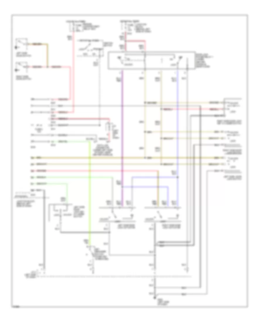
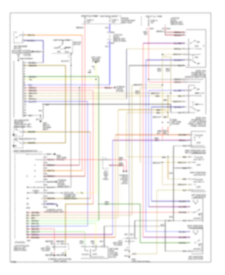
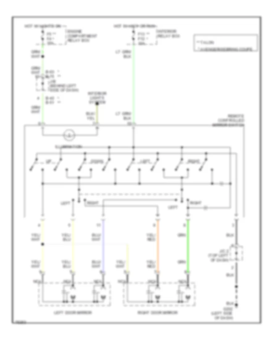
POWER MIRRORS
Power Mirror Wiring Diagram for Dodge Avenger 1997
 https://portal-diagnostov.com/license.html
Automotive Electricians Portal FZCO
Automotive Electricians Portal FZCO
https://portal-diagnostov.com/license.html
https://portal-diagnostov.com/license.html
Automotive Electricians Portal FZCO
Automotive Electricians Portal FZCOList of elements for Power Mirror Wiring Diagram for Dodge Avenger 1997:
- * **
- * avenger/sebring coupe
- ** *
- ** talon
- B-43 b-51
- B-63 b-75
- Down
- Engine compartment relay box
- F13 f12 10a
- F5 f4 15a
- G202 (left side of dash)
- Hot in accy or run
- Hot w/ lights on
- Illumination
- Interior lights system
- Interior relay box
- J/b (behind left side of dash)
- J/c 2 (top left of dash)
- Left
- Left door mirror
- Nca
- Remote controlled mirror switch
- Right
- Right door mirror
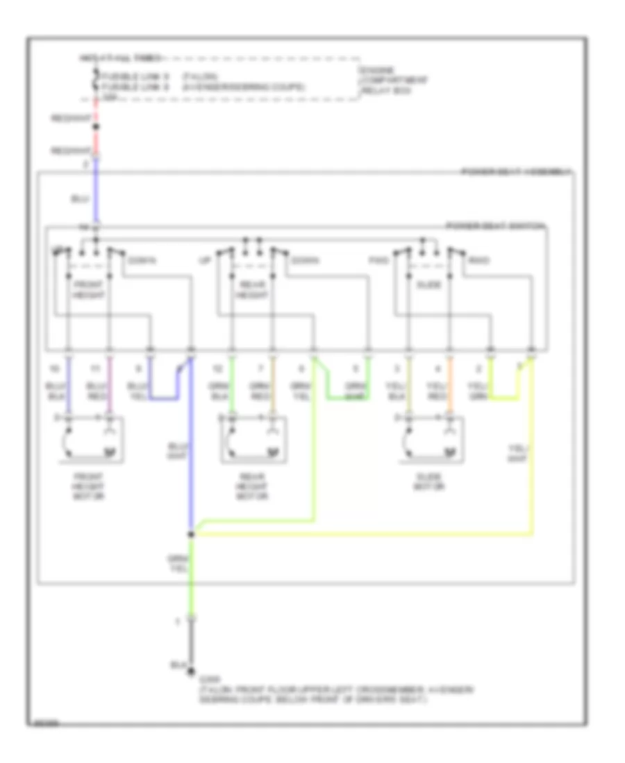
POWER SEATS
Power Seat Wiring Diagrams for Dodge Avenger 1997
 https://portal-diagnostov.com/license.html
Automotive Electricians Portal FZCO
Automotive Electricians Portal FZCO
https://portal-diagnostov.com/license.html
https://portal-diagnostov.com/license.html
Automotive Electricians Portal FZCO
Automotive Electricians Portal FZCOList of elements for Power Seat Wiring Diagrams for Dodge Avenger 1997:
- (talon) (avenger/sebring coupe)
- Down
- Engine compartment relay box
- Front height
- Front height motor
- Fusible link 9 fusible link 8 30a
- Fwd
- G300 (talon: front floor upper left crossmember; avenger/ sebring coupe: below front of driver's seat)
- Hot at all times
- Power seat assembly
- Power seat switch
- Rear height
- Rear height motor
- Rwd
- Slide
- Slide motor
POWER TOP/SUNROOF
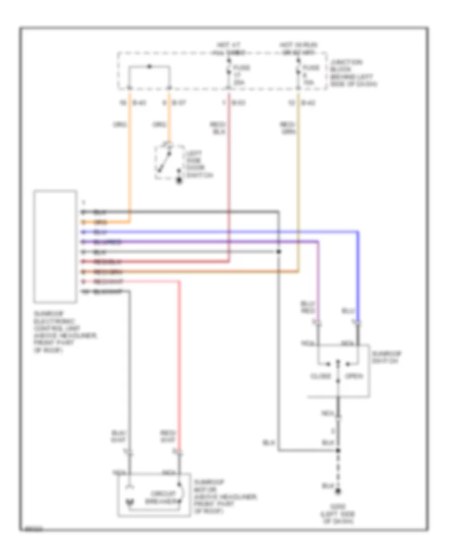
Power Top/Sunroof Wiring Diagrams for Dodge Avenger 1997
 https://portal-diagnostov.com/license.html
Automotive Electricians Portal FZCO
Automotive Electricians Portal FZCO
https://portal-diagnostov.com/license.html
https://portal-diagnostov.com/license.html
Automotive Electricians Portal FZCO
Automotive Electricians Portal FZCOList of elements for Power Top/Sunroof Wiring Diagrams for Dodge Avenger 1997:
- B-42
- B-43
- B-53
- B-57
- Circuit breaker
- Close
- Fuse 10a
- Fuse 20a
- G202 (left side of dash)
- Hot at all times
- Hot in run or start
- Junction block (behind left side of dash)
- Left side door switch
- Nca
- Open
- Sunroof electronic control unit (above headliner, front part of roof)
- Sunroof motor (above headliner, front part of roof)
- Sunroof switch
POWER WINDOWS
Power Window Wiring Diagram for Dodge Avenger 1997
 https://portal-diagnostov.com/license.html
Automotive Electricians Portal FZCO
Automotive Electricians Portal FZCO
https://portal-diagnostov.com/license.html
https://portal-diagnostov.com/license.html
Automotive Electricians Portal FZCO
Automotive Electricians Portal FZCOList of elements for Power Window Wiring Diagram for Dodge Avenger 1997:
- (under left side of dash, near center console) data link connector
- (w/o anti-theft) (w/ anti-theft)
- B-39
- B-40
- B-41
- B-42
- B-43
- B-57
- B-63
- Circuit
- Door locks system
- Door switch (left)
- Door switch (right)
- Down
- Engine compartment
- Etacs ecu
- Fuse 10a
- Fuse 8 10a
- Fusible link 8 30a
- G202 (left side of dash)
- G300 (below driver's seat)
- Hot at all times
- Hot in on or start
- Interior lights system
- J/c 1 (left side of dash)
- J/c 2 (left side of dash)
- Junction block (behind left side of dash)
- Left power window motor
- Left window
- Lock switch
- Luggage compartment light switch
- Nca
- Off
- One- touch down
- Power window main switch
- Power window sub switch
- Power windows relay (under left side of dash)
- Relay box (left side of engine compt, in front of wheel housing)
- Right power window motor
- Right window
- Trunk lid switch
- W/ anti-theft
- W/o anti-theft
RADIO
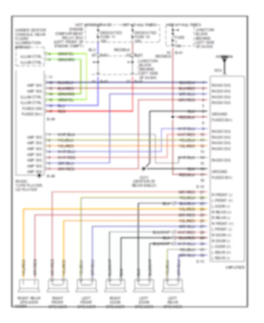
Radio Wiring Diagrams, with Amplifier for Dodge Avenger 1997
 https://portal-diagnostov.com/license.html
Automotive Electricians Portal FZCO
Automotive Electricians Portal FZCO
https://portal-diagnostov.com/license.html
https://portal-diagnostov.com/license.html
Automotive Electricians Portal FZCO
Automotive Electricians Portal FZCOList of elements for Radio Wiring Diagrams, with Amplifier for Dodge Avenger 1997:
- (under center console, near floor) illumination module
- Amp sig
- Amplifier
- Antenna
- B-41
- B-42
- B-43
- B-48
- B-49
- B-63
- Dedicated fuse 10 10a
- Dedicated fuse 11 10a
- E-12
- E-13
- Engine compartment relay box (left front of engine compt)
- Fuse 15a
- Fused b(+)
- Fused ign
- G311 (center of rear shelf)
- Ground
- Hot at all times
- Hot in run or acc
- Illum ctrl
- Junction block (behind left side of dash)
- L door (+)
- L door (-)
- L front (+)
- L front (-)
- L rear (+)
- L rear (-)
- Left door speaker
- Left front speaker
- Left rear speaker
- Nca
- R door (+)
- R door (-)
- R front (+)
- R front (-)
- R rear (+)
- R rear (-)
- Radio sig
- Radio, tape player, cd player
- Red
- Right door speaker
- Right front speaker
- Right rear speaker
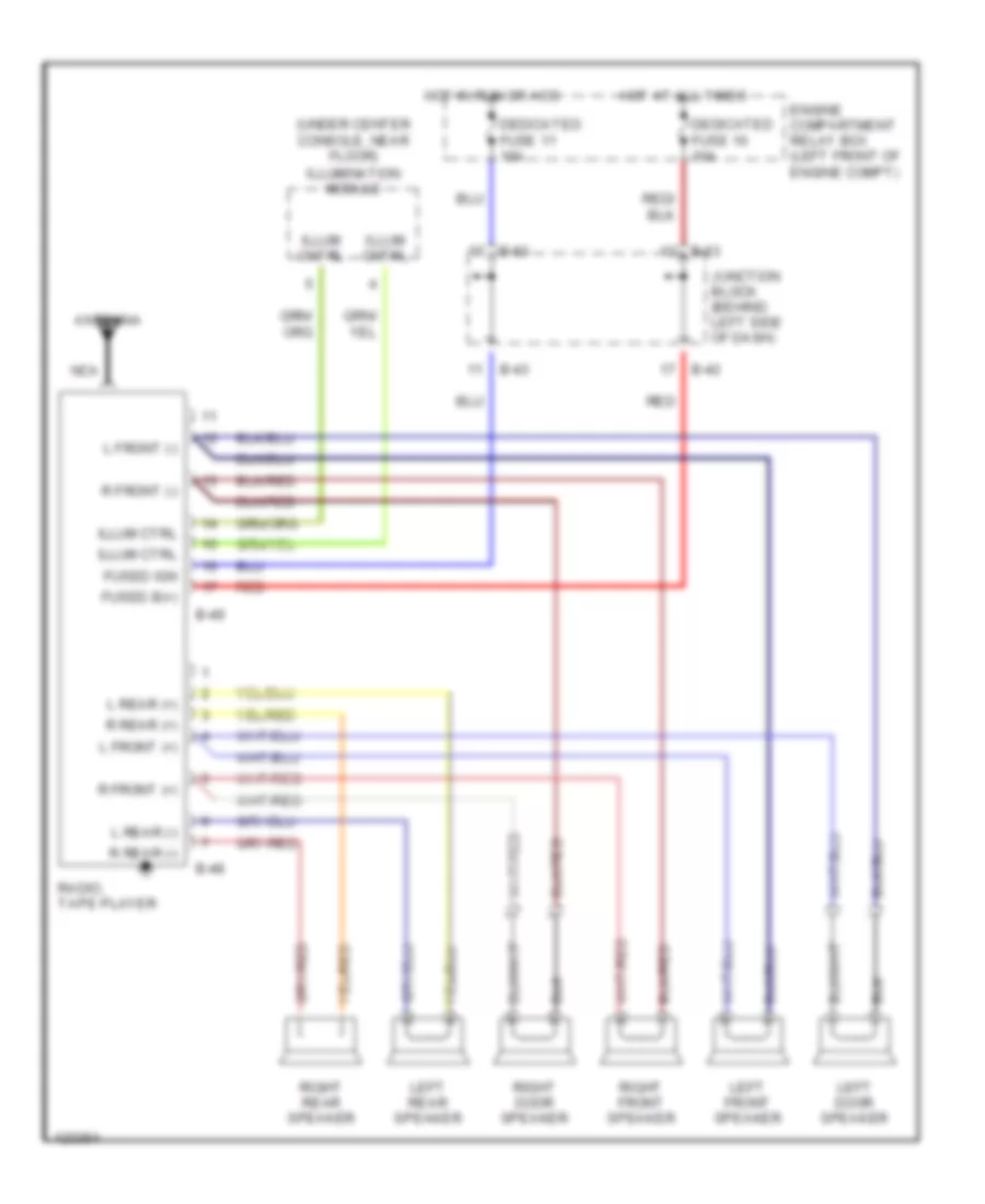
Radio Wiring Diagrams, without Amplifier for Dodge Avenger 1997
 https://portal-diagnostov.com/license.html
Automotive Electricians Portal FZCO
Automotive Electricians Portal FZCO
https://portal-diagnostov.com/license.html
https://portal-diagnostov.com/license.html
Automotive Electricians Portal FZCO
Automotive Electricians Portal FZCOList of elements for Radio Wiring Diagrams, without Amplifier for Dodge Avenger 1997:
- (under center console, near floor)
- Antenna
- B-42
- B-43
- B-48
- B-49
- B-63
- Dedicated fuse 10 10a
- Dedicated fuse 11 10a
- Engine compartment relay box (left front of engine compt)
- Fused b(+)
- Fused ign
- Hot at all times
- Hot in run or acc
- Illum cntrl
- Illum ctrl
- Illumination module
- Junction block (behind left side of dash)
- L front (+)
- L front (-)
- L rear (+)
- L rear (-)
- Left door speaker
- Left front speaker
- Left rear speaker
- Nca
- R front (+)
- R front (-)
- R rear (+)
- R rear (-)
- Radio, tape player
- Red
- Right door speaker
- Right front speaker
- Right rear speaker
STARTING/CHARGING
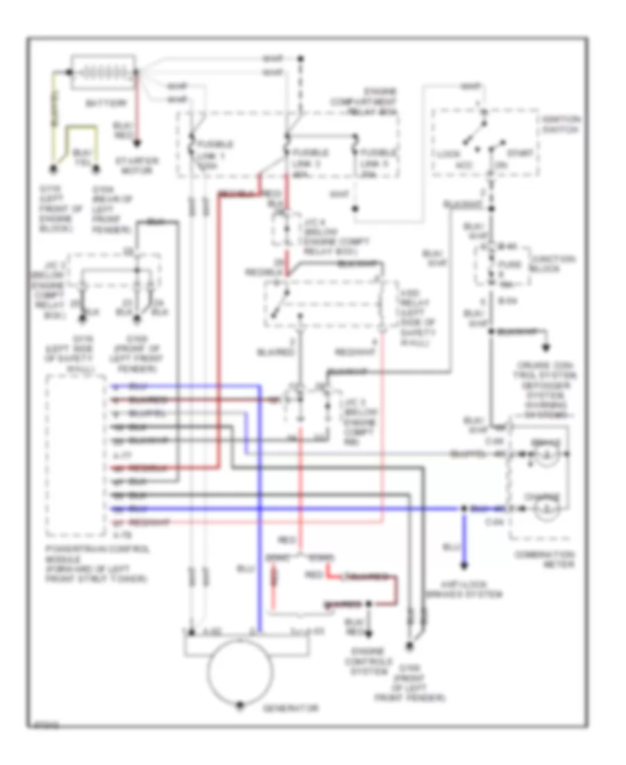
Charging Wiring Diagram for Dodge Avenger 1997
 https://portal-diagnostov.com/license.html
Automotive Electricians Portal FZCO
Automotive Electricians Portal FZCO
https://portal-diagnostov.com/license.html
https://portal-diagnostov.com/license.html
Automotive Electricians Portal FZCO
Automotive Electricians Portal FZCOList of elements for Charging Wiring Diagram for Dodge Avenger 1997:
- A-02
- A-03
- A-77
- A-78
- Acc
- Anti-lock brakes system
- Asd relay (left side of safety wall)
- B-41
- B-54
- Battery
- Brake
- C-04
- C-06
- Charge
- Combination meter
- Cruise con- trol system, defogger system, warning systems
- Dohc
- Engine compartment relay box
- Engine controls system
- Fuse 10a
- Fusible
- G100 (front of left front fender)
- G104 (rear of left front fender)
- G110 (left front of engine block)
- G116 (left side of safety wall)
- Generator
- Ignition switch
- J/c 3 (below engine compt rb)
- J/c 3 (below engine compt relay box)
- J/c 4 (below engine compt relay box)
- Junction block
- Link 1 120a
- Link 3 40a
- Link 5 30a
- Lock
- Powertrain control module (forward of left front strut tower)
- Red
- Sohc
- Start
- Starter motor
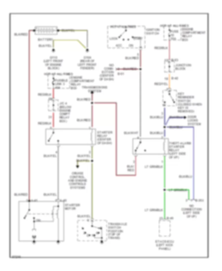
Starting Wiring Diagram, with A/T & Anti-theft for Dodge Avenger 1997
 https://portal-diagnostov.com/license.html
Automotive Electricians Portal FZCO
Automotive Electricians Portal FZCO
https://portal-diagnostov.com/license.html
https://portal-diagnostov.com/license.html
Automotive Electricians Portal FZCO
Automotive Electricians Portal FZCOList of elements for Starting Wiring Diagram, with A/T & Anti-theft for Dodge Avenger 1997:
- A-40
- A-41
- Acc
- B-35x
- B-40
- B-42
- B-51
- B-63
- Battery
- Cruise control, and engine controls systems
- Door locks system
- Engine compartment relay box
- Etacs-ecu (left kick panel)
- Fuse 10a
- Fusible link 3 40a
- G104 (rear of left front fender)
- G110 (left front of engine block)
- Hot at all times
- Ignition switch
- J/c 4 (below engine compt relay box)
- Junction block
- Key reminder switch (closed when key is removed)
- Lock
- No conn- ection (center of dash)
- No connection (left side of i/p)
- Start
- Starter motor
- Starter relay (center of dash)
- Theft-alarm starter relay (left side of i/p)
- Transaxle switch position (top of trans)
- Transmissions system
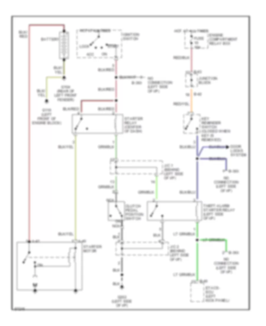
Starting Wiring Diagram, with M/T & Anti-theft for Dodge Avenger 1997
 https://portal-diagnostov.com/license.html
Automotive Electricians Portal FZCO
Automotive Electricians Portal FZCO
https://portal-diagnostov.com/license.html
https://portal-diagnostov.com/license.html
Automotive Electricians Portal FZCO
Automotive Electricians Portal FZCOList of elements for Starting Wiring Diagram, with M/T & Anti-theft for Dodge Avenger 1997:
- A-40
- A-41
- Acc
- B-36x
- B-40
- B-42
- B-63
- Battery
- Clutch pedal position switch
- Door locks system
- Engine compartment relay box
- Etacs- ecu (left kick panel)
- Fuse 10a
- G104 (rear of left front fender)
- G110 (left front of engine block)
- G202 (left side of i/p)
- Hot at all times
- Ignition switch
- J/c 1 (behind left side of i/p)
- J/c 2 (behind left side of i/p)
- Junction block
- Key reminder switch (closed when key is removed)
- Lock
- Nca
- No connection (left side of i/p)
- Start
- Starter motor
- Starter relay (center of dash)
- Theft-alarm starter relay (left side of i/p)
Starting Wiring Diagram, without Anti-theft for Dodge Avenger 1997
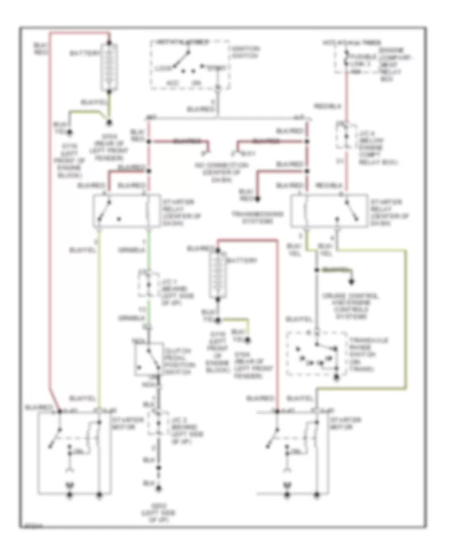 https://portal-diagnostov.com/license.html
Automotive Electricians Portal FZCO
Automotive Electricians Portal FZCO
https://portal-diagnostov.com/license.html
https://portal-diagnostov.com/license.html
Automotive Electricians Portal FZCO
Automotive Electricians Portal FZCOList of elements for Starting Wiring Diagram, without Anti-theft for Dodge Avenger 1997:
- A-40
- A-41
- A/t
- Acc
- B-51
- Battery
- Clutch pedal position switch
- Cruise control, and engine controls systems
- Engine compart- ment relay box
- Fusible link 3 40a
- G104 (rear of left front fender)
- G110 (left front of engine block)
- G202 (left side of i/p)
- Hot at all times
- Ignition switch
- J/c 1 (behind left side of i/p)
- J/c 2 (behind left side of i/p)
- J/c 4 (below engine compt relay box)
- Lock
- M/t
- Nca
- No connection (center of dash)
- Start
- Starter motor
- Starter relay (center of dash)
- Transaxle range switch (on trans)
- Transmissions systems
SUPPLEMENTAL RESTRAINTS
Supplemental Restraint Wiring Diagram for Dodge Avenger 1997
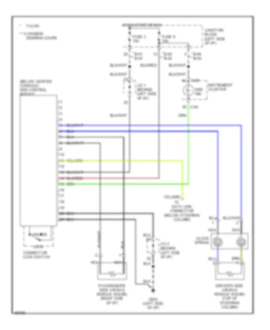 https://portal-diagnostov.com/license.html
Automotive Electricians Portal FZCO
Automotive Electricians Portal FZCO
https://portal-diagnostov.com/license.html
https://portal-diagnostov.com/license.html
Automotive Electricians Portal FZCO
Automotive Electricians Portal FZCOList of elements for Supplemental Restraint Wiring Diagram for Dodge Avenger 1997:
- (behind left side of i/p)
- (below center console) srs control module
- * b-50 b-42
- * b-51 b-43
- * b-66 b-54
- ** avenger/
- C-04
- C-05
- Clock spring
- Connector lock switch
- Data link connector (below steering column)
- Driver's side air bag module (squib) (top of steering column)
- Fuse 3 10a
- Fuse 8 10a
- G202 (left side of i/p)
- Hot in start or run
- Instrument cluster
- J/c 1 (behind left side of i/p)
- J/c 2
- Junction block (left side of i/p)
- Lock
- Nca
- Passenger's side air bag module (squib) (right side of i/p)
- Sebring coupe
- Srs ind.
- Talon
- Unlock
TRANSMISSION
Transmission Wiring Diagram (1 of 3) for Dodge Avenger 1997
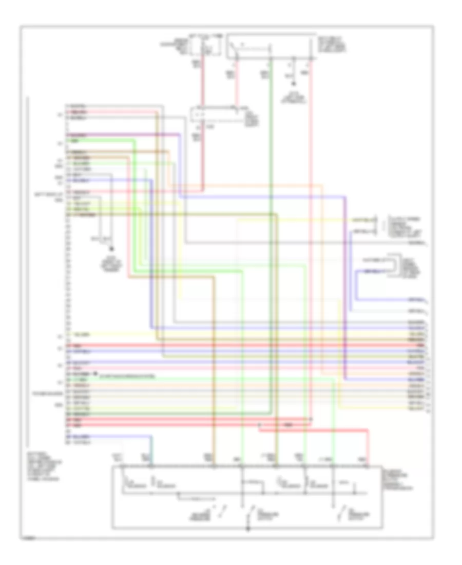 https://portal-diagnostov.com/license.html
Automotive Electricians Portal FZCO
Automotive Electricians Portal FZCO
https://portal-diagnostov.com/license.html
https://portal-diagnostov.com/license.html
Automotive Electricians Portal FZCO
Automotive Electricians Portal FZCOList of elements for Transmission Wiring Diagram (1 of 3) for Dodge Avenger 1997:
- 2-4 pressure switch
- 2-4 solenoid
- A-29
- Batt back up
- Eatx relay (on firewall, at left rear of eng compt)
- Eatx-ecm (2.0l: under center console; 2.5l: left side of eng compt, in front of wheel housing)
- Engine compartment relay box
- Fl 3 30a
- G100 (front of left front fender)
- G116 (left side of firewall)
- Gnd
- Hot at all times
- Input speed sensor (at rear of eng)
- J/c4 (front of eng compt)
- L/r reverse pressure
- L/r solenoid
- Od pressure switch
- Od solenoid
- Output speed sensor (on trans- mission at left output shaft)
- Pnk
- Power source
- Red
- Solenoid & pressure switch assembly (transmission)
- Starting/charging system
- Ud solenoid
Transmission Wiring Diagram (2 of 3) for Dodge Avenger 1997
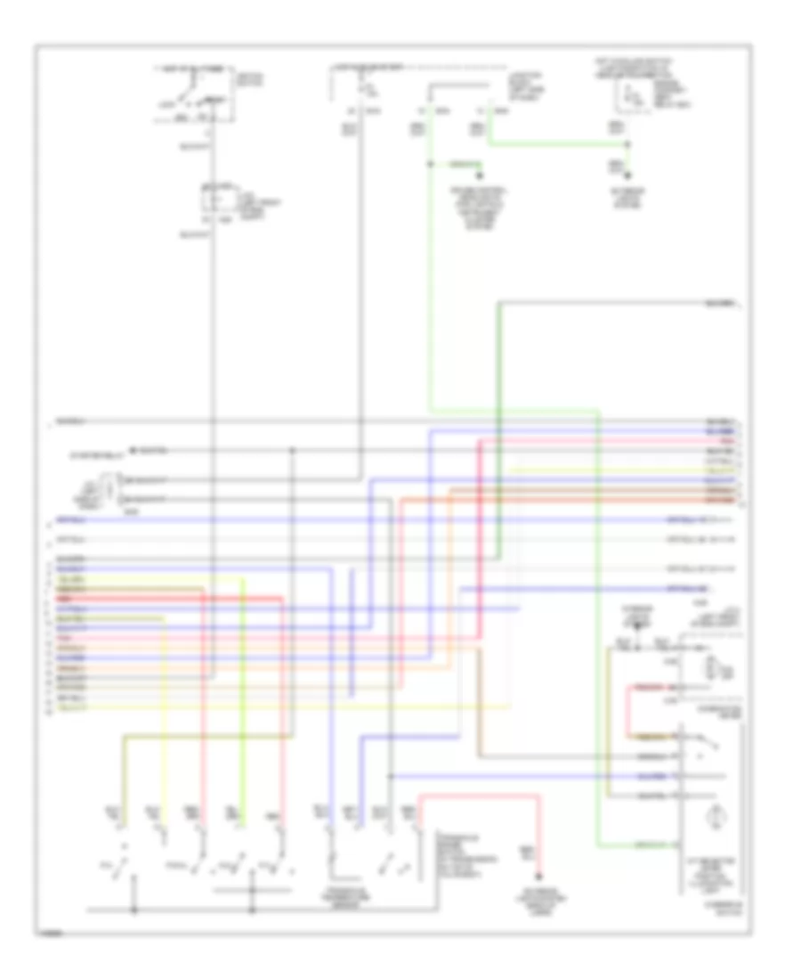 https://portal-diagnostov.com/license.html
Automotive Electricians Portal FZCO
Automotive Electricians Portal FZCO
https://portal-diagnostov.com/license.html
https://portal-diagnostov.com/license.html
Automotive Electricians Portal FZCO
Automotive Electricians Portal FZCOList of elements for Transmission Wiring Diagram (2 of 3) for Dodge Avenger 1997:
- A-28
- A-29
- A/t selector lever position illumination light
- Acc
- B-05
- B-43
- B-54
- B-63
- C-05
- C-06
- Combination meter
- Cruise control, headlights (fog lights) & instrument cluster system
- Engine compart- ment relay box
- Exterior lights system
- Exterior lights system (back-up lamps)
- F3 10a
- F4 15a
- Hot at all times
- Hot in on or start
- Hot w/column switch (lighting switch) in head or tail position
- Igniton switch
- Interior lights system
- J/c 1 (left side of dash)
- J/c 4 (left front of eng compt)
- J/c3 (left front of eng compt)
- Junction block (left side of dash)
- Lock
- N.d.l.
- O/d off
- Overdrive switch
- P.3.l.
- P.n.
- P.r.n.l.
- Pnk
- Red
- Start
- Starter relay
- Transaxle range switch (in transmission, on top of valve body)
- Transaxle temperature sensor
Transmission Wiring Diagram (3 of 3) for Dodge Avenger 1997
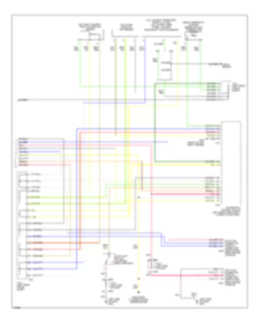 https://portal-diagnostov.com/license.html
Automotive Electricians Portal FZCO
Automotive Electricians Portal FZCO
https://portal-diagnostov.com/license.html
https://portal-diagnostov.com/license.html
Automotive Electricians Portal FZCO
Automotive Electricians Portal FZCOList of elements for Transmission Wiring Diagram (3 of 3) for Dodge Avenger 1997:
- (2.0l: on right side of eng, near oil filter; 2.5l: on right side of bell housing) crankshaft position sensor
- (left side of dash) g202
- (near thermostat housing) engine coolant temperature sensor
- (on intake manifold) map sensor
- (on throttle body) throttle position sensor
- 2.0l
- 2.5l
- A-29
- A-77
- A-78
- B-06
- Data link connector (partial) (under left side of dash, b-29 near center console)
- Data link connector (partial) (under left side of dash, near center b-30 console)
- G100 (front of left front fender)
- Instrument cluster system (speedometer)
- J/c 2 (left side of dash)
- J/c 3 (left front of eng compt)
- J/c 4 (left front of eng compt)
- Knock sensor
- Pnk
- Powertrain control module (left side of eng compt, in front of battery)
- Stop light switch (on brake pedal bracket)
WARNING SYSTEMS
Warning System Wiring Diagrams for Dodge Avenger 1997
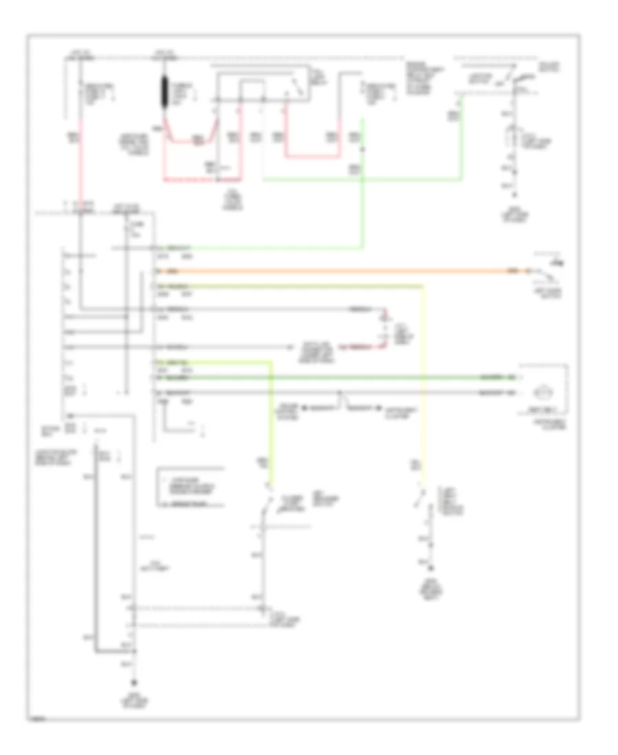 https://portal-diagnostov.com/license.html
Automotive Electricians Portal FZCO
Automotive Electricians Portal FZCO
https://portal-diagnostov.com/license.html
https://portal-diagnostov.com/license.html
Automotive Electricians Portal FZCO
Automotive Electricians Portal FZCOList of elements for Warning System Wiring Diagrams for Dodge Avenger 1997:
- : chrysler
- : eagle talon
- sebring coupe & dodge avenger
- (closed w/key removed)
- 2.0l turbo talon models
- B-39 b-47
- B-40 b-48
- B-41 b-49
- B-42
- B-43
- B-50
- B-51
- B-54
- B-57
- B-63
- B-66
- B-69
- B-75
- Chrysler, dodge, and 2.0l talon models
- Column switch
- Cruise control system
- Data link connector (under left side of dash)
- Dedicated fuse 10 fuse 11 10a
- Dedicated fuse 4 fuse 5 15a
- Engine compartment relay box (in front of wheel housing)
- Etacs- ecu
- Fuse 10a
- Fusible link 4 link 5 40a
- G202 (left side of dash)
- G300 (below driver's seat)
- Head
- Hot at all times
- Hot in on and start
- Instrument cluster
- J/c 1 (left side of dash)
- J/c 2 (left side of dash)
- Junction block (behind left side of dash)
- Key reminder switch
- Left door switch
- Left seat belt buckle switch
- Lighting switch
- Off
- Red
- Seat belt
- Tail
- Tail- lamp relay
- W/o anti-theft
WIPER/WASHER
Wiper/Washer Wiring Diagram for Dodge Avenger 1997
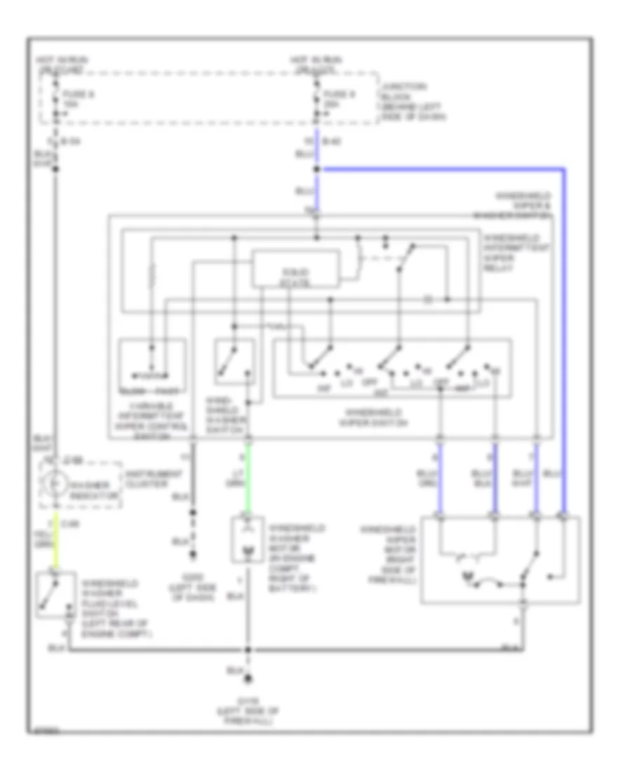 https://portal-diagnostov.com/license.html
Automotive Electricians Portal FZCO
Automotive Electricians Portal FZCO
https://portal-diagnostov.com/license.html
https://portal-diagnostov.com/license.html
Automotive Electricians Portal FZCO
Automotive Electricians Portal FZCOList of elements for Wiper/Washer Wiring Diagram for Dodge Avenger 1997:
- B-42
- B-54
- C-06
- Fuse 8 10a
- Fuse 9 20a
- G116 (left side of firewall)
- G202 (left side of dash)
- Hot in run or accy
- Hot in run or start
- Instrument cluster
- Int
- Junction block (behind left side of dash)
- Off
- Off int
- Slow fast
- Solid state
- Variable intermittent wiper control switch
- Washer indicator
- Wind- shield washer switch
- Windshield intermittent wiper relay
- Windshield washer fluid level switch (left rear of engine compt)
- Windshield washer motor (in engine compt, right of battery)
- Windshield wiper & washer switch
- Windshield wiper motor (right side of firewall)
- Windshield wiper switch

 Čeština
 Dansk
Dansk Deutsch
 Ελληνικά
 English
 English
 Español
 Suomi
Suomi Français
 Français
 עברית
עברית Hrvatski
 Magyar
 Italiano
 한국어
한국어 Nederlands
 Polski
 Português
 Português
 Română
 Русский
 Slovenčina
 Slovenščina
 Svenska
 Türkçe
 中文 (中国)
