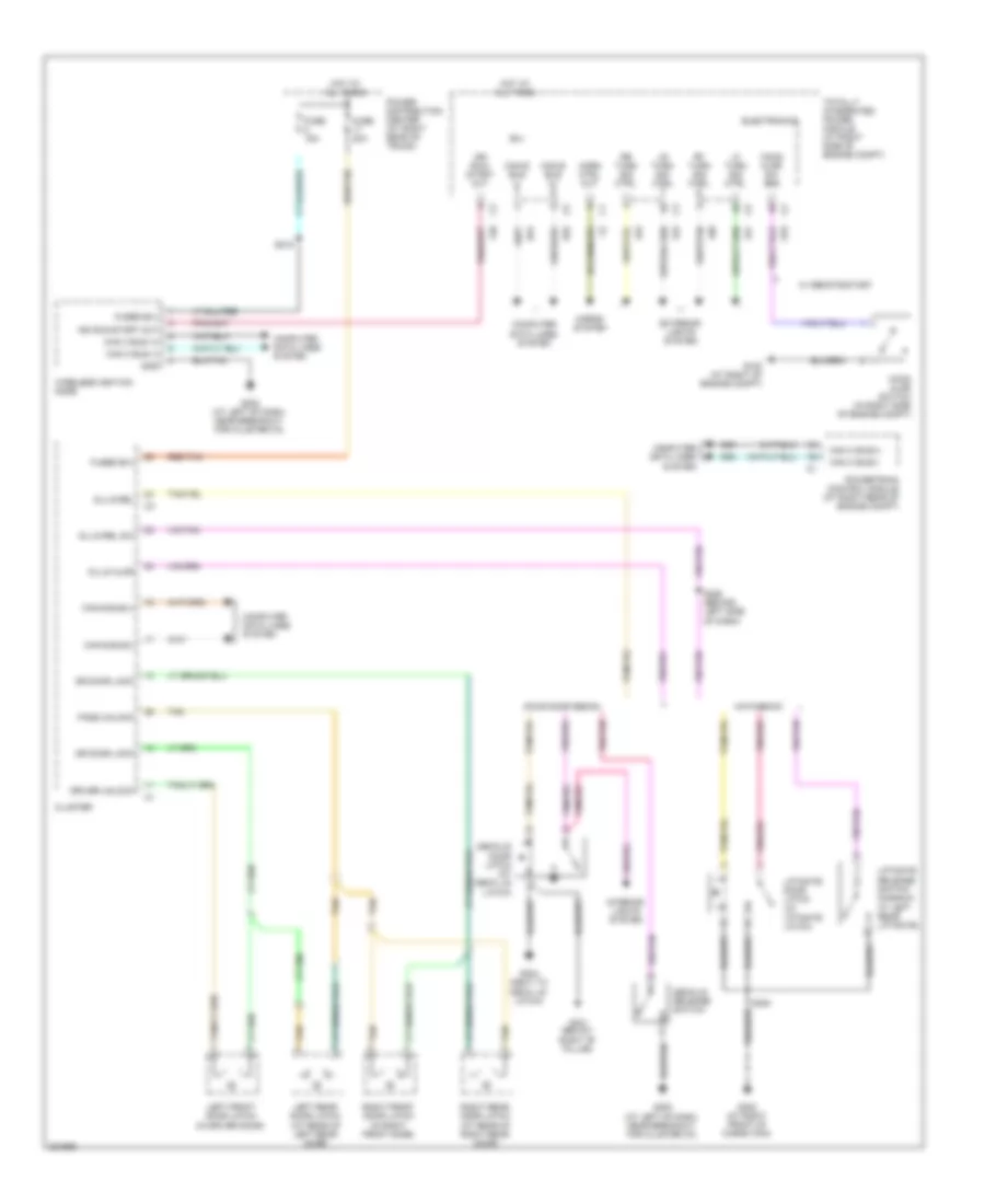
AIR CONDITIONING
Automatic A/C Wiring Diagram (1 of 2) for Dodge Charger R/T 2008
 https://portal-diagnostov.com/license.html
Automotive Electricians Portal FZCO
Automotive Electricians Portal FZCO
https://portal-diagnostov.com/license.html
https://portal-diagnostov.com/license.html
Automotive Electricians Portal FZCO
Automotive Electricians Portal FZCO
List of elements for Automatic A/C Wiring Diagram (1 of 2) for Dodge Charger R/T 2008:
- (at right rear of engine compt) powertrain control module
- (at right side of engine compt) integrated power module
- 5v sply
- 87a
- A/c cltch ctrl
- A/c cltch ctrl out
- A/c compressor clutch (on front of engine)
- A/c heater control
- A/c press sens gnd
- A/c pressure trans- ducer sig
- A/c pressure transducer (at left rear of engine compt)
- A23
- Aat sig
- Ambient air temperature sensor (at right front of engine compt)
- Auto hdlmp sig
- Bus (+)
- Bus (-)
- C115
- C121
- C13
- C18
- C21
- C252
- C255
- C266
- C268
- C52
- C55
- C56
- C66
- C68
- C918
- Can b bus (+)
- Can b bus (-)
- Can c
- Cltch
- Computer data lines system
- Ctrl
- Ctrl feed
- D54
- D55
- D64
- D65
- Defogger system
- Drv lt blend dr
- Drv lt blend dr com
- Drv mode dr
- Drv mode dr com
- Drv panel lamps
- Drv recir dr
- Drv recir dr com
- Drv rt blend dr
- Drv rt blend dr com
- E12
- Ect sig
- Electronics
- Engine controls system
- Engine coolant temperature sensor (3.5l: at front of engine) (6.1l: at left front of engine)
- Evaporator temperature sensor (on center of hvac unit)
- F500
- F891
- Ft blower ctrl
- Fuse 40a
- Fuse 50a
- Fused b (+)
- Fused b(+)
- G101 (at right front of engine compt)
- G102 (at right of engine compt)
- G139
- G200 (at left side of dash, near breakout for ignition switch)
- G31
- G39
- G931
- G939
- Gnd
- Hi rly ctrl
- Hot at all times
- Interior lights system
- K900
- L24
- Left blend door actuator (at left side of hvac unit)
- Mode door actuator (on left side of hvac unit)
- Radiator 87a fan high relay
- Radiator fan
- Radiator fan control relay
- Radiator fan high/ low 87a control relay
- Recirculation door actuator (on right side of hvac unit)
- Right blend door actuator (on center of hvac unit)
- Rly ctrl
- Rly out
- S111 (3.5l w/ 4 speed transmission) (5.7l/6.1l: at right rear side of engine)
- S115 (except 6.1l)
- Sens gnd
- Sens sig
- Sig
- Sun sens rtn
- Sun sens sig 1
- Sun sens sig 2
- Sun sensor (at top center of dash)
- Z909
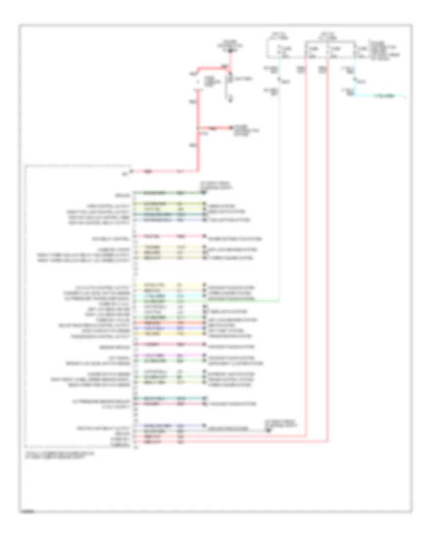
Automatic A/C Wiring Diagram (2 of 2) for Dodge Charger R/T 2008
 https://portal-diagnostov.com/license.html
Automotive Electricians Portal FZCO
Automotive Electricians Portal FZCO
https://portal-diagnostov.com/license.html
https://portal-diagnostov.com/license.html
Automotive Electricians Portal FZCO
Automotive Electricians Portal FZCOList of elements for Automatic A/C Wiring Diagram (2 of 2) for Dodge Charger R/T 2008:
- (at right side of dash) g201
- Blower motor (on right side of hvac unit)
- Blower motor sply
- C56
- Front blower power module (on center of hvac unit)
- Ft blower ctrl
- Fuse 10a
- Fuse 30a
- Fused run rly out
- Gnd
- Hot at all times
- Hot w/ run relay energized
- Power distribution center (at right rear of trunk)
- S200
- S210
- Z134
- Z908
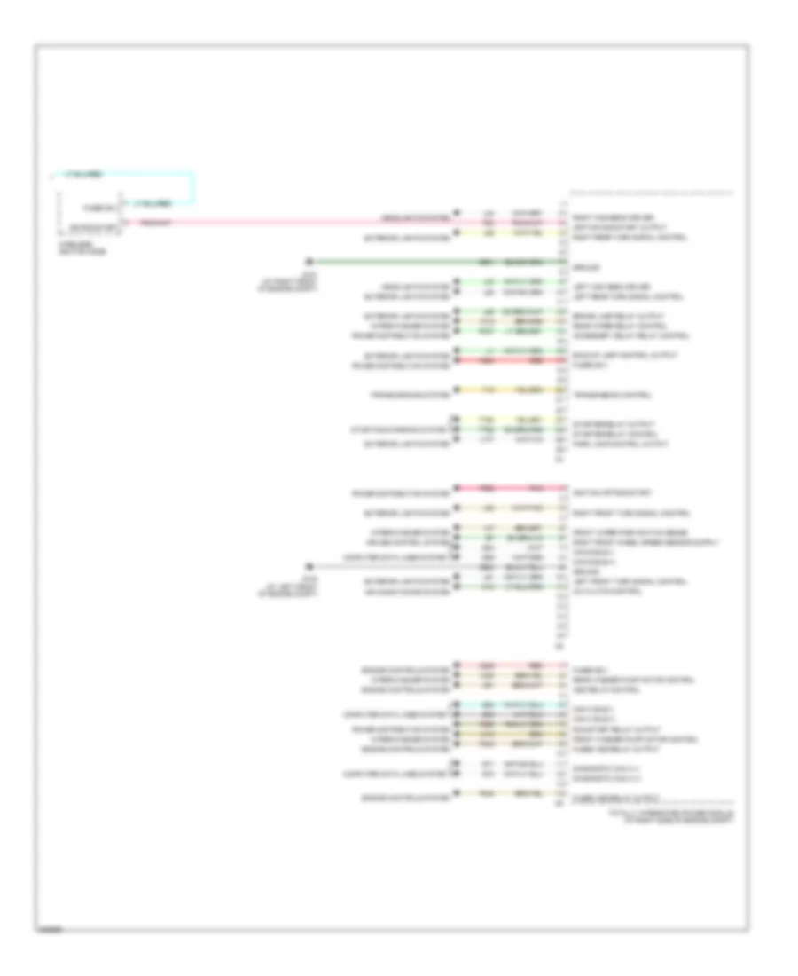
Manual A/C Wiring Diagram (1 of 2) for Dodge Charger R/T 2008
 https://portal-diagnostov.com/license.html
Automotive Electricians Portal FZCO
Automotive Electricians Portal FZCO
https://portal-diagnostov.com/license.html
https://portal-diagnostov.com/license.html
Automotive Electricians Portal FZCO
Automotive Electricians Portal FZCOList of elements for Manual A/C Wiring Diagram (1 of 2) for Dodge Charger R/T 2008:
- (at right rear of engine compt) powertrain control module
- (at right side of engine compt) integrated power module
- 5v sply
- 87a
- A/c cltch ctrl
- A/c cltch ctrl out
- A/c heater control
- A/c press sens gnd
- A/c pressure trans- ducer sig
- A/c pressure transducer (at left rear of engine compt)
- A23
- Aat sig
- Ambient air temperature sensor (at right front of engine compt)
- Blower sw pos sig
- Bus (+)
- Bus (-)
- C105
- C115
- C121
- C13
- C18
- C21
- C255
- C266
- C268
- C55
- C66
- C68
- C70
- C71
- C72
- C73
- C850
- C918
- Can b bus (+)
- Can b bus (-)
- Can c
- Cltch
- Cluster
- Computer data lines system
- Ctrl
- Ctrl feed
- D54
- D55
- D64
- D65
- Defogger system
- Drv lt blend dr
- Drv lt blend dr com
- Drv mode dr
- Drv mode dr com
- Drv panel lamps
- Drv recir dr
- Drv recir dr com
- E12
- E22
- Ect sig
- Electronics
- Engine controls system
- Engine coolant temperature sensor (2.7l & 3.5l: at front of engine) (6.1l: at left front of engine)
- Evaporator temperature sensor (on center of hvac unit)
- F500
- F891
- Front blower motor resistor block (at center hvac unit)
- Ft blower high spd
- Ft blower low spd
- Ft blower m1 spd
- Ft blower m2 spd
- Fuse 40a
- Fuse 50a
- Fused b (+) (i.o.d)
- Fused b(+)
- Fused run rly out
- G101 (at right front of engine compt)
- G102 (at right of engine compt)
- G200 (at left side of dash, near breakout for ignition switch)
- G201 (at right side of dash)
- G31
- G931
- Gnd
- Hi rly ctrl
- Hot at all times
- Hvac mux ctrl
- Ind dimmer sig
- Interior lights system
- K900
- Left blend door actuator (at left side of hvac unit)
- Mode door actuator (on left side of hvac unit)
- Radiator 87a fan high relay
- Radiator fan
- Radiator fan control relay
- Radiator fan high/ low 87a control relay
- Recirculation door actuator (on right side of hvac unit)
- Rly ctrl
- Rly out
- S110 (at right rear of engine compt)
- S111 (3.5l w/ 4 speed transmission) (2.7l: at left side of engine) (5.7l/6.1l: at right rear side of engine)
- Sens gnd
- Sens sig
- Sig
- Z908
- Z909
Manual A/C Wiring Diagram (2 of 2) for Dodge Charger R/T 2008
 https://portal-diagnostov.com/license.html
Automotive Electricians Portal FZCO
Automotive Electricians Portal FZCO
https://portal-diagnostov.com/license.html
https://portal-diagnostov.com/license.html
Automotive Electricians Portal FZCO
Automotive Electricians Portal FZCOList of elements for Manual A/C Wiring Diagram (2 of 2) for Dodge Charger R/T 2008:
- A/c compressor clutch (on front of engine)
- Blower motor (on right side of hvac unit)
- Fuse 10a
- Fuse 30a
- G102 (at right of engine compt)
- Hot at all times
- Hot w/ run relay energized
- Power distribution center (at right rear of trunk)
- S115 (except 6.1l)
- S200
- S210
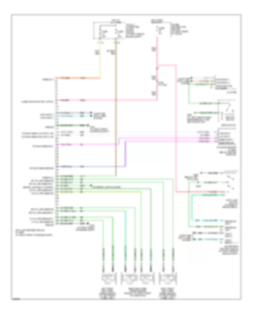
ANTI-LOCK BRAKES
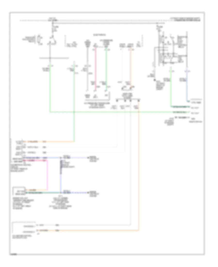
Anti-lock Brakes Wiring Diagram for Dodge Charger R/T 2008
 https://portal-diagnostov.com/license.html
Automotive Electricians Portal FZCO
Automotive Electricians Portal FZCO
https://portal-diagnostov.com/license.html
https://portal-diagnostov.com/license.html
Automotive Electricians Portal FZCO
Automotive Electricians Portal FZCOList of elements for Anti-lock Brakes Wiring Diagram for Dodge Charger R/T 2008:
- 30a
- 50a
- A107
- A111
- Anti-lock brakes module (w/ esp) (at right front of engine compt)
- B15
- B16
- B221
- Bank switch
- Brake lamp relay control
- Brake sw sig 1
- Brake sw sig 2
- Can b bus (+)
- Can b bus (-)
- Can c bus (+)
- Can c bus (-)
- Cluster
- Computer data lines system
- D51
- D52
- D64
- D65
- Dynamic sens ground
- Dynamic sens high data link
- Dynamic sens low data link
- Dynamic sens sply
- Dynamics sensor (w/ esp) (below center console)
- Esp off switch
- Exterior lights system
- F202
- Fuse
- Fused b (+)
- Fused ign run-start output
- G101 (at right front of engine compt)
- G200 (at left side of dash, near breakout for ignition switch)
- G300 (below left "b" pillar)
- G94
- Ground
- High data
- Hot at all times
- Hot in run or start
- Left front abs wheel speed sensor (at left front wheel well)
- Lf whl spd sens sig
- Lf whl spd sens sply
- Low data
- Lr whl spd sens sig
- Lr whl spd sens sply
- Nca
- Power distribution center (at right rear of trunk)
- Powertrain control module (at right rear of engine compt)
- Rear abs wheel speed sensor (magnum: at right front of cargo pan)
- Rf whl spd sens sig
- Rf whl spd sens sply
- Right front abs wheel speed sensor (at right front wheel well)
- Rr whl spd sens sig
- Rr whl spd sens sply
- S126 (w/ acc)
- S309
- Sens ground
- Stop lamp switch (at base of brake pedal)
- Tan/ red
- Tan/red
- Totally integrated power module (at right side of engine compt)
- Traction ctrl sw sense
- Z903
ANTI-THEFT
Anti-theft Wiring Diagram for Dodge Charger R/T 2008
 https://portal-diagnostov.com/license.html
Automotive Electricians Portal FZCO
Automotive Electricians Portal FZCO
https://portal-diagnostov.com/license.html
https://portal-diagnostov.com/license.html
Automotive Electricians Portal FZCO
Automotive Electricians Portal FZCOList of elements for Anti-theft Wiring Diagram for Dodge Charger R/T 2008:
- B(+)
- Can b bus (+)
- Can b bus (-)
- Can b bus(+)
- Can b bus(-)
- Can c bus (+)
- Can c bus (-)
- Can c bus(+)
- Can c bus(-)
- Cluster
- Computer data lines system
- D54
- D55
- D64
- D65
- Decklid door latch (at deck lid latch)
- Decklid release switch
- Dl/lg ajar
- Dl/lg rel
- Dl/lg rel sw
- Dr door lock
- Driver unlock
- Electronics
- Exterior lights system
- F20
- Four door sedan
- Fuse 15a
- Fuse 20a
- Fused b(+)
- G102 (at right of engine compt)
- G202 (at left of dash, near breakout for cluster c3)
- G301 (below
- G302 (at right front of cargo pan)
- G304 (next to deck lid latch)
- G70
- Gnd
- Hatchback
- Hood ajar sw sns
- Hood ajar switch (in right side of engine compt)
- Horn ctrl out
- Horns system
- Hot at all times
- Ign run- start out
- Ign run-start out
- Interior lights system
- L60
- L61
- L62
- L63
- Left front door latch (in driver door)
- Left rear door latch (at rear of left rear door)
- Lf turn sig ctrl
- Liftgate door latch (at liftgate latch)
- Liftgate release switch (magnum: at left rear liftgate)
- Lr turn sig ctrl
- Pass unlock
- Power distribution center (at right rear of trunk)
- Powertrain control module (at right rear of engine compt)
- Red/tan
- Rf turn sig ctrl
- Right "b" pillar)
- Right front door latch (in right front door)
- Right rear door latch (at rear of right rear door)
- Rr turn sig ctrl
- S215
- S228 (behind left side of dash)
- S354
- Tan
- Totally integrated power module (at right side of engine compt)
- W/ remote start
- Wireless ignition node
BODY CONTROL MODULES
Body Control Modules Wiring Diagram (1 of 2) for Dodge Charger R/T 2008
 https://portal-diagnostov.com/license.html
Automotive Electricians Portal FZCO
Automotive Electricians Portal FZCO
https://portal-diagnostov.com/license.html
https://portal-diagnostov.com/license.html
Automotive Electricians Portal FZCO
Automotive Electricians Portal FZCOList of elements for Body Control Modules Wiring Diagram (1 of 2) for Dodge Charger R/T 2008:
- (at right front of engine compt) g101
- A/c clutch control output
- A/c pressure sensor ground
- A/c pressure transducer signal
- A107
- A11
- A111
- A22
- A72
- Aat signal
- Adjustable pedals control output
- Air conditioning system
- Anti-lock brakes system
- Anti-theft system
- B(+)
- B20
- Battery
- Brake fluid level switch sense
- C18
- C918
- Cooling fans system
- Cruise control system
- Exterior lights system
- F891
- F923
- Front fog lamp control output
- Front wiper high/low relay high speed output
- Front wiper high/low relay low speed output
- Fuse 15a
- Fuse 20a
- Fuse 40a
- Fused b(+)
- Fused b(+) (i.o.d.)
- Fused b(+) (pump)
- Fused b(+) (valve)
- G31
- G70
- G931
- Ground
- Hazard switch sense
- Headlights system
- Hood ajar switch sense
- Horn control output
- Horns system
- Hot at all times
- Instrument cluster system
- L43
- L44
- L89
- L91
- Left low beam driver
- N210
- N23
- N24
- Pass through post
- Power distribution center (at right rear of trunk)
- Power distribution system
- Rad fan control relay output
- Rad fan high relay output
- Rad fan high/low control feed
- Rear wiper park switch sense
- Red
- Right front wheel speed sensor signal
- Right low beam driver
- Run relay control
- S138
- S215
- S328
- Seats system
- Sensor ground
- T16
- Tan/red
- Totally integrated power module (at right side of engine compt)
- Transmission control output
- Transmissions system
- W17
- Washer fluid level switch sense
- Wiper/washer system
- X13
- Z901
Body Control Modules Wiring Diagram (2 of 2) for Dodge Charger R/T 2008
 https://portal-diagnostov.com/license.html
Automotive Electricians Portal FZCO
Automotive Electricians Portal FZCO
https://portal-diagnostov.com/license.html
https://portal-diagnostov.com/license.html
Automotive Electricians Portal FZCO
Automotive Electricians Portal FZCOList of elements for Body Control Modules Wiring Diagram (2 of 2) for Dodge Charger R/T 2008:
- A/c clutch control
- A209
- A904
- Accessory delay relay control
- Air conditioning system
- Asd relay control
- Backup lamp control output
- Brake lamp relay output
- C13
- Can b bus (+)
- Can b bus (-)
- Can c bus (+)
- Can c bus (-)
- Computer data lines system
- Cruise control system
- D54
- D55
- D64
- D65
- D71
- D72
- Diagnostic can c (+)
- Diagnostic can c (-)
- Engine controls system
- Exterior lights system
- F20
- F342
- F343
- F902
- F950
- Front washer pump motor control
- Front wiper park switch sense
- Fused asd relay output
- Fused b(+)
- G100 (at left front of engine compt)
- G101 (at right front of engine compt)
- Ground
- Headlights system
- Ign run-start
- Ignition off-run-start
- Ignition run-start output
- K51
- L33
- L34
- L53
- L60
- L61
- L62
- L63
- L777
- Left front turn signal control
- Left high beam driver
- Left rear turn signal control
- P307
- Park lamp control output
- Pnk
- Power distribution system
- Rear washer pump motor control
- Rear wiper relay control
- Red
- Right front turn signal control
- Right high beam driver
- Right rear turn signal control
- Run/start relay output
- Starter relay control
- Starter relay output
- Starting/charging system
- T15
- T750
- T752
- Totally integrated power module (at right side of engine compt)
- Transmission control
- Transmissions system
- W10
- W12
- W20
- Wiper/washer system
- Wireless ignition node
- Z901
- Z902
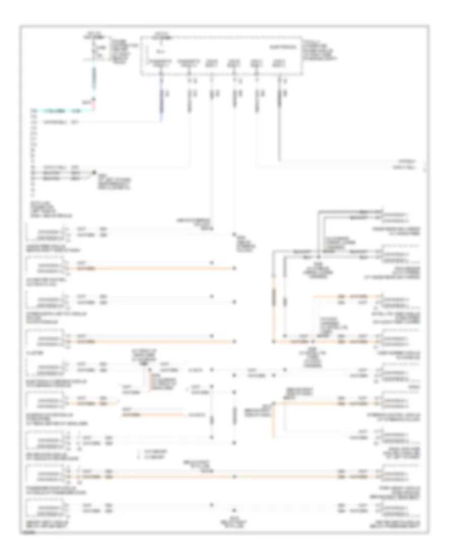
COMPUTER DATA LINES
Computer Data Lines Wiring Diagram (1 of 2) for Dodge Charger R/T 2008
 https://portal-diagnostov.com/license.html
Automotive Electricians Portal FZCO
Automotive Electricians Portal FZCO
https://portal-diagnostov.com/license.html
https://portal-diagnostov.com/license.html
Automotive Electricians Portal FZCO
Automotive Electricians Portal FZCOList of elements for Computer Data Lines Wiring Diagram (1 of 2) for Dodge Charger R/T 2008:
- (above steering column) s204
- (at front of headliner) (w/ sunroof) s338
- (behind right side of dash) s218
- (below right "b" pillar) s318
- (in audio harness) (w/ satellite video) s392
- (in interior mirror jumper harness) s396
- A/c-heater control (automatic a/c)
- A106
- B (+)
- Can b bus (+)
- Can b bus (-)
- Can c bus (+)
- Can c bus (-)
- Cluster
- D54
- D55
- D64
- D65
- D71
- D72
- Data link connector (left side of dash, above pedals)
- Diagnostic can c (+)
- Diagnostic can c (-)
- Driver door module (at middle of driver door)
- Electronic overhead module (in overhead console)
- Electronics
- Fuse 15a
- G202 (at left of dash, near breakout for cluster c3)
- Hands free module (behind right side of dash)
- Heated seats module (below passenger seat)
- Hot at all times
- Inside rearview mirror (w/ hands free)
- Interface-police/taxi module (police) (in mini-console)
- Memory seat module (below driver seat)
- Park assist module (parktronics) (behind right rear seat)
- Passenger door module (in middle of passenger door)
- Power distribution center (at right rear of trunk)
- Radio
- Radio amplifier (midline ii/highline) (at left of dash)
- Rain sensor (auto wipers) (at inside rearview mirror)
- S205 (above steering column)
- S215
- S219 (behind right side of dash)
- S319 (below right "b" pillar)
- S339 (w/ sunroof) (at front of headliner)
- S393 (w/ satellite video) (in audio harness)
- S395 (in interior mirror jumper harness)
- Satellite video module (if equipped) (on audio-video jumper)
- Steering control module (at steering column)
- Sunroof motor/module (if equipped) (at rear center of headliner)
- Totally integrated power module (at right side of engine compt)
- Video screen module (in console)
- W/ evic
- W/ memory
- W/o evic
- W/o memory
- Z910
Computer Data Lines Wiring Diagram (2 of 2) for Dodge Charger R/T 2008
 https://portal-diagnostov.com/license.html
Automotive Electricians Portal FZCO
Automotive Electricians Portal FZCO
https://portal-diagnostov.com/license.html
https://portal-diagnostov.com/license.html
Automotive Electricians Portal FZCO
Automotive Electricians Portal FZCOList of elements for Computer Data Lines Wiring Diagram (2 of 2) for Dodge Charger R/T 2008:
- (at right side of engine compt) s122
- (at right side of engine compt) s124
- (at top right of radiator yoke) (w/ acc) s170
- (behind left side of dash) s206
- (below center console) (console 5 speed) s391
- (in engine compt) s139
- (in instrument panel harness) s237
- (w/ 5 speed) (at left rear of engine compt, near grommet to dash) s171
- 6.1l
- Adaptive cruise control module (acc) (behind left grille)
- Antilock brakes module (esp) (at right front of engine compt)
- Can c bus (+)
- Can c bus (-)
- Chrysler
- Com-lin tire press moni lan
- D64
- D65
- Dodge
- Electronic shift module (column w/ 5 speed) transmission) (at bottom of steering column)
- Except 6.1l
- Left front tire pressure transponder (if equipped) (at left front side of engine compt)
- Occupant restraint controller module (in center console)
- Powertrain control module (at right rear of engine compt)
- Right front tire pressure transponder (if equipped) (at right front of engine compt)
- Right rear tire pressure transponder (if equipped) (in right rear wheel well)
- S141 (behind right side of dash)
- S168 (w/ acc) (at top right of radiator yoke)
- S169 (at left rear of engine compt, near grommet to dash) (w/ 5 speed)
- S207 (behind left side of dash)
- S235 (in instrument panel harness)
- S390 (console 5 speed) (below center console)
- Shift lever assembly (console w/ 5 speed) transmission)
- Steering control module (at steering column)
- Transmission control module (w/ 5 speed) transmission) (below steering column)
- W/ 4 speed transmission
- W/ 5 speed transmission
- Wireless ignition node
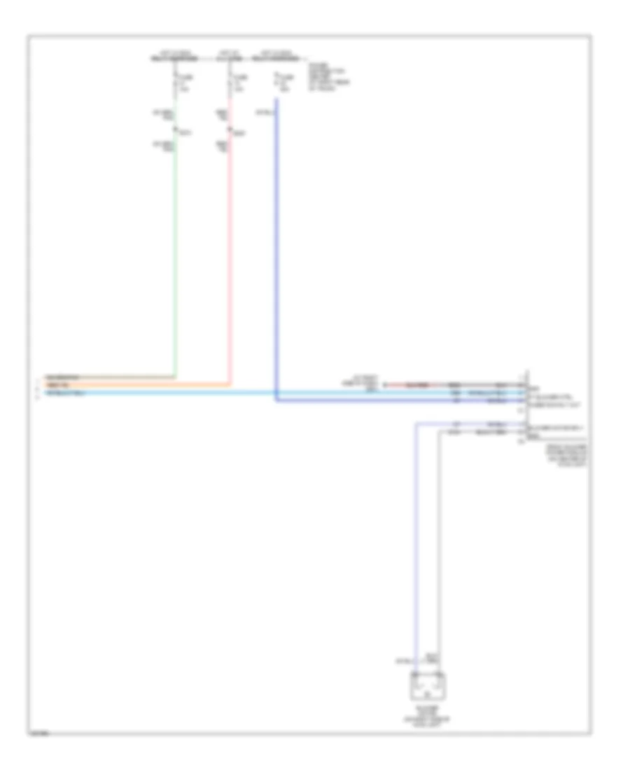
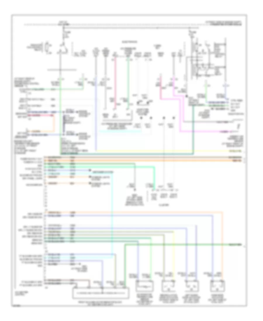
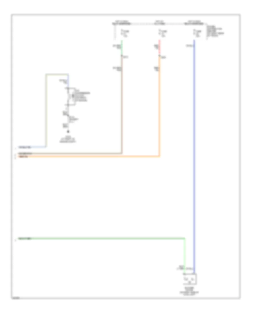
COOLING FAN
Cooling Fan Wiring Diagram for Dodge Charger R/T 2008
 https://portal-diagnostov.com/license.html
Automotive Electricians Portal FZCO
Automotive Electricians Portal FZCO
https://portal-diagnostov.com/license.html
https://portal-diagnostov.com/license.html
Automotive Electricians Portal FZCO
Automotive Electricians Portal FZCOList of elements for Cooling Fan Wiring Diagram for Dodge Charger R/T 2008:
- (at right side of engine compt) integrated power module
- 5v sply
- 87a
- A/c cltch ctrl
- A/c heater control (automatic a/c)
- A/c press sens gnd
- A/c pressure trans- ducer sig
- A/c pressure transducer (at left rear of engine compt)
- Bus (+)
- Bus (-)
- C13
- C18
- C918
- Can b bus (+)
- Can b bus (-)
- Can c
- Cltch
- Computer data lines system
- Ctrl
- Ctrl feed
- D54
- D55
- D64
- D65
- Ect sig
- Electronics
- Engine controls system
- Engine coolant temperature sensor (2.7l/3.5l: at front of engine) (6.1l: at left front of engine)
- F891
- Fuse 40a
- Fuse 50a
- G101 (at right front of engine compt)
- G102 (at right of engine compt)
- Gnd
- Hi rly ctrl
- Hot at all times
- K900
- Powertrain control module (at right rear of engine compt)
- Radiator 87a fan high relay
- Radiator fan
- Radiator fan control relay
- Radiator fan high/ low 87a control relay
- Rly ctrl
- Rly out
- S111 (3.5l w/ 4 speed transmission) (2.7l: at left side of engine) (5.7l/6.1l: at right rear side of engine)
- Sens gnd
- Sig
CRUISE CONTROL
Cruise Control Wiring Diagram for Dodge Charger R/T 2008
 https://portal-diagnostov.com/license.html
Automotive Electricians Portal FZCO
Automotive Electricians Portal FZCO
https://portal-diagnostov.com/license.html
https://portal-diagnostov.com/license.html
Automotive Electricians Portal FZCO
Automotive Electricians Portal FZCOList of elements for Cruise Control Wiring Diagram for Dodge Charger R/T 2008:
- (at left of dash, near breakout for cluster c3) g202
- 5v sply
- 87a
- A913
- Accel
- Accelerator pedal position sensor (at adjustable pedal assembly)
- Adaptive cruise control module (w/ acc) (behind left grille)
- Antilock brakes module (w/ esp) (at right front of engine compt)
- App 1 sig
- App 2 sig
- App gnd 1
- App gnd 2
- App sens gnd 1
- App sens gnd 2
- App sig 1
- App sig 2
- B221
- Can b bus+
- Can b bus-
- Can c bus+
- Can c bus-
- Cluster
- Coast
- Computer data lines system
- Cruise control switch
- D54
- D55
- D64
- D65
- Electronics
- Engine controls system
- Etc motor (+)
- Etc motor (-)
- Etc mtr (+)
- Etc mtr (-)
- Evic display
- Exterior lights system
- F202
- F855
- F856
- Fuse 10a
- Fuse 5a
- Fused b+
- G101 (at right front of engine compt)
- Gnd
- Ground
- Hot at all times
- Hot in on or start
- Infrared transceiver
- K122
- K124
- K126
- K167
- K22
- K23
- K29
- K400
- K922
- L53
- Lamp activation relay (in power distribution) center)
- Nca
- On/ off
- Power distribution center (at right rear of truck)
- Powertrain control module (at right rear of engine compt)
- Processor
- Resume/cancel
- Rf whl speed
- Right front wheel speed sensor (w/o abs) right front abs wheel speed sensor (w/ abs) (at right front wheel well)
- Run-start
- S105 (at right rear of engine compt)
- S126 (w/ acc)
- S230 (police)
- S302 (at body floor, near passenger door)
- Set
- Steering control module (at steering column)
- Stop lamp rly
- Stop lamp switch (at base of brake pedal)
- Throttle body (2.7l/3.5l/5.7l: on top of intake manifold) (6.1l: at top of intake manifold)
- Totally integrated power module (at right side of engine compt)
- Tp sens gnd
- Tp sig 1
- Tp sig 2
- W/ abs
- W/o abs
- Z901
- Z910
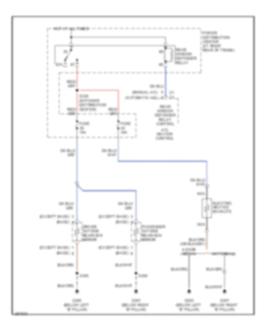
DEFOGGERS
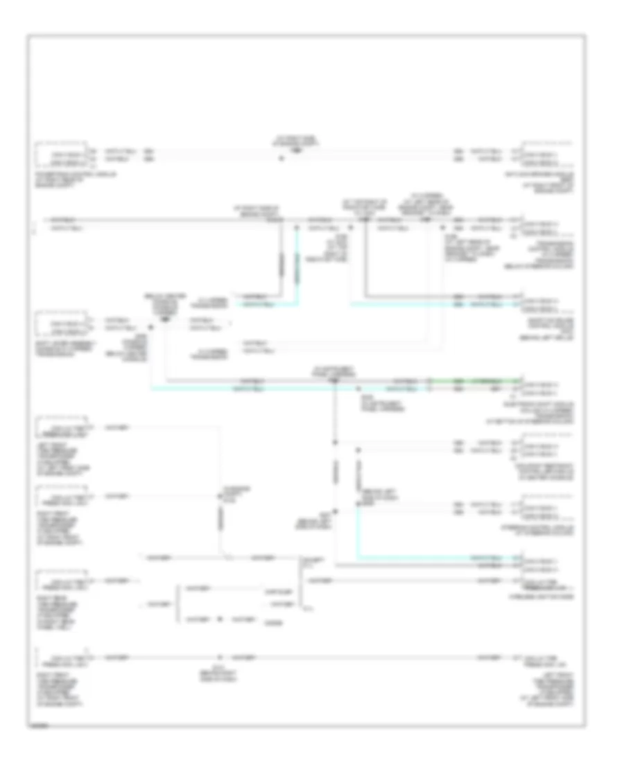
Defoggers Wiring Diagram for Dodge Charger R/T 2008
 https://portal-diagnostov.com/license.html
Automotive Electricians Portal FZCO
Automotive Electricians Portal FZCO
https://portal-diagnostov.com/license.html
https://portal-diagnostov.com/license.html
Automotive Electricians Portal FZCO
Automotive Electricians Portal FZCOList of elements for Defoggers Wiring Diagram for Dodge Charger R/T 2008:
- (automatic a/c)
- (base)
- (except base)
- (manual a/c)
- 4 door sedan
- 87a
- A/c- heater control
- Driver outside rearview mirror
- Electric heated backlite
- Fuse 10a
- Fuse 30a
- G300 (below left "b" pillar)
- G301 (below right "b" pillar)
- Hatchback
- Hot at all times
- Nca
- Passenger outside rearview mirror
- Power distribution center (at right rear of trunk)
- Rear window defogger relay
- Rear window defogger relay control
- S355
- S360
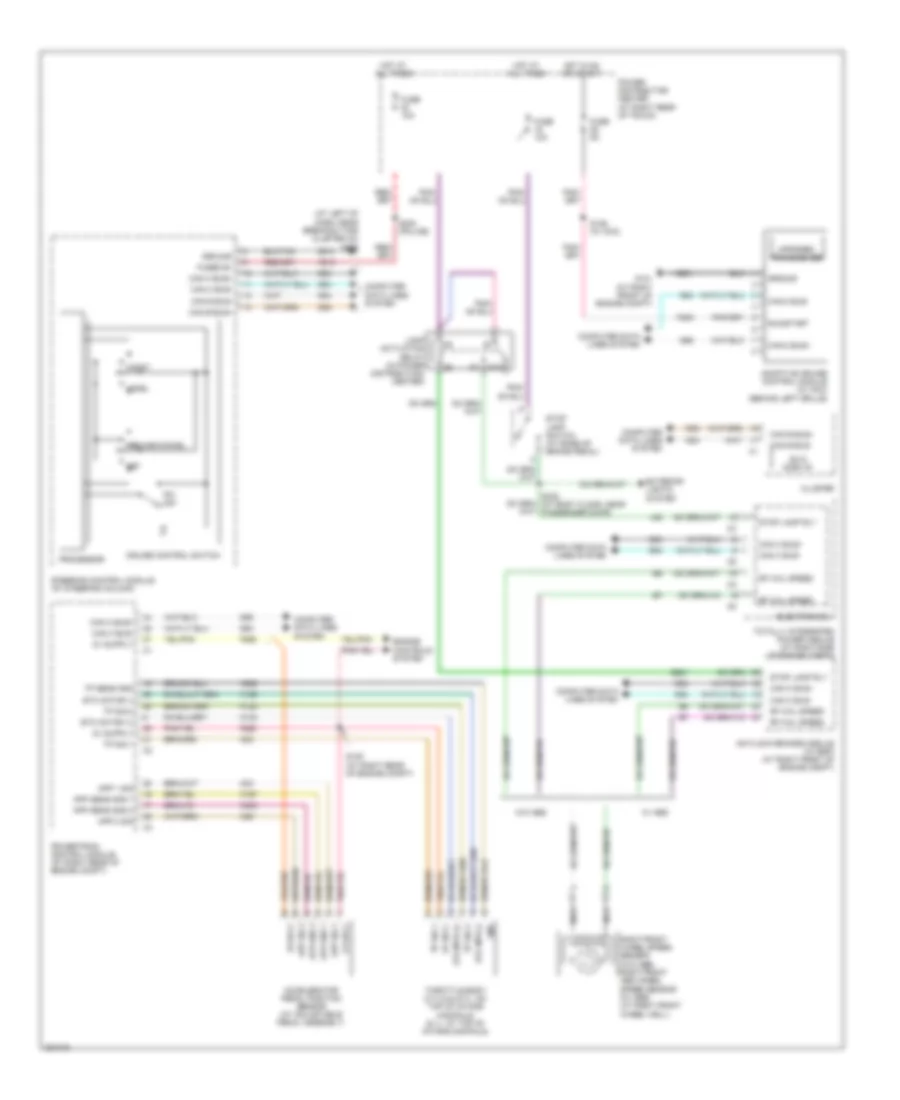
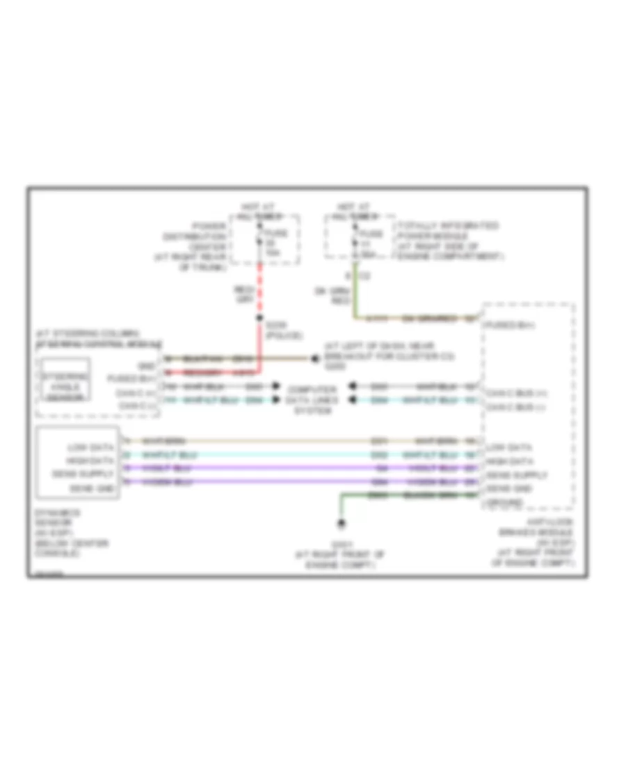
ELECTRONIC POWER STEERING
Electronic Power Steering Wiring Diagram for Dodge Charger R/T 2008
 https://portal-diagnostov.com/license.html
Automotive Electricians Portal FZCO
Automotive Electricians Portal FZCO
https://portal-diagnostov.com/license.html
https://portal-diagnostov.com/license.html
Automotive Electricians Portal FZCO
Automotive Electricians Portal FZCOList of elements for Electronic Power Steering Wiring Diagram for Dodge Charger R/T 2008:
- (at left of dash, near breakout for cluster c3) g202
- (at steering column) steering control module
- A111
- A913
- Anti-lock brakes module (w/ esp) (at right front of engine compt)
- Can c (+)
- Can c (-)
- Can c bus (+)
- Can c bus (-)
- Computer data lines system
- D51
- D52
- D64
- D65
- Dynamics sensor (w/ esp) (below center console)
- Fuse 10a
- Fuse 30a
- Fused b(+)
- G101 (at right front of engine compt)
- G94
- Gnd
- Ground
- High data
- Hot at all times
- Low data
- Power distribution center (at right rear of trunk)
- S230 (police)
- Sens gnd
- Steering angle sensor
- Totally integrated power module (at right side of engine compartment)
- Z903
- Z910
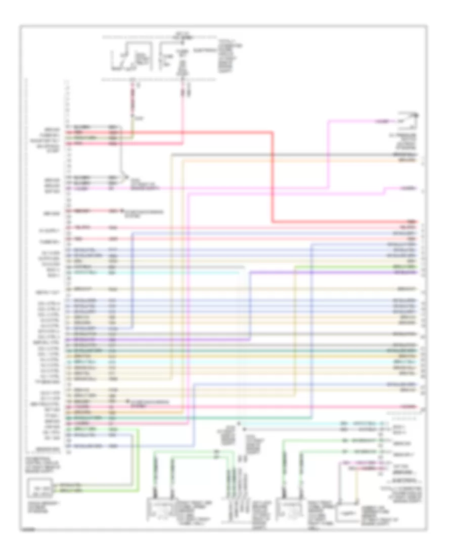
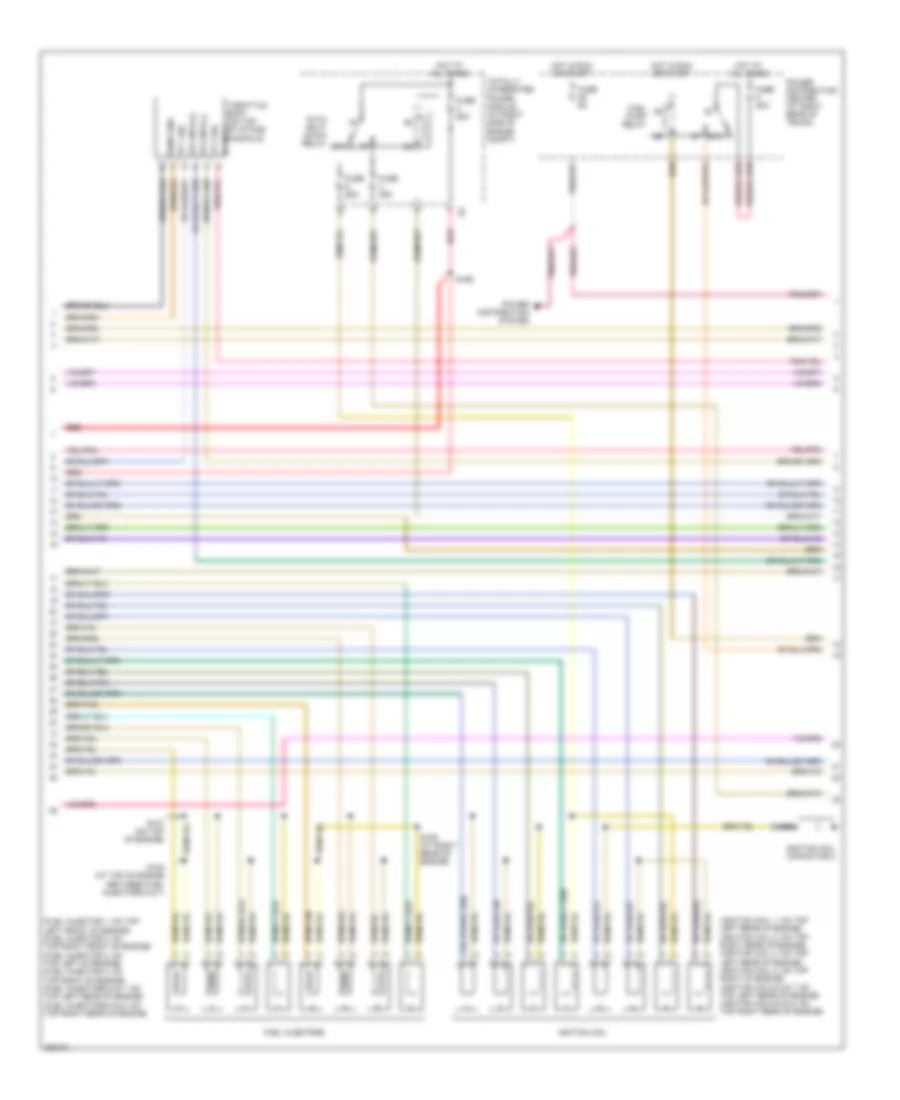
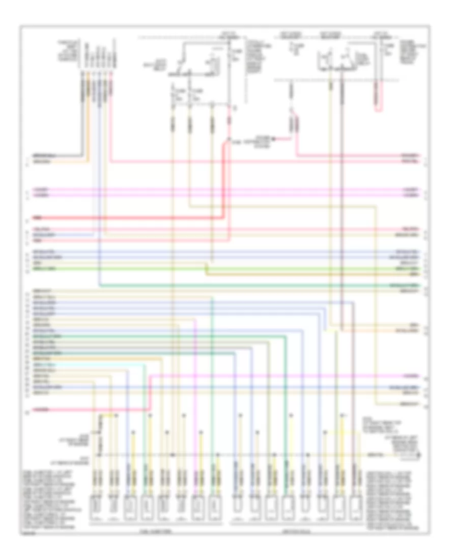
ENGINE PERFORMANCE
2.7L
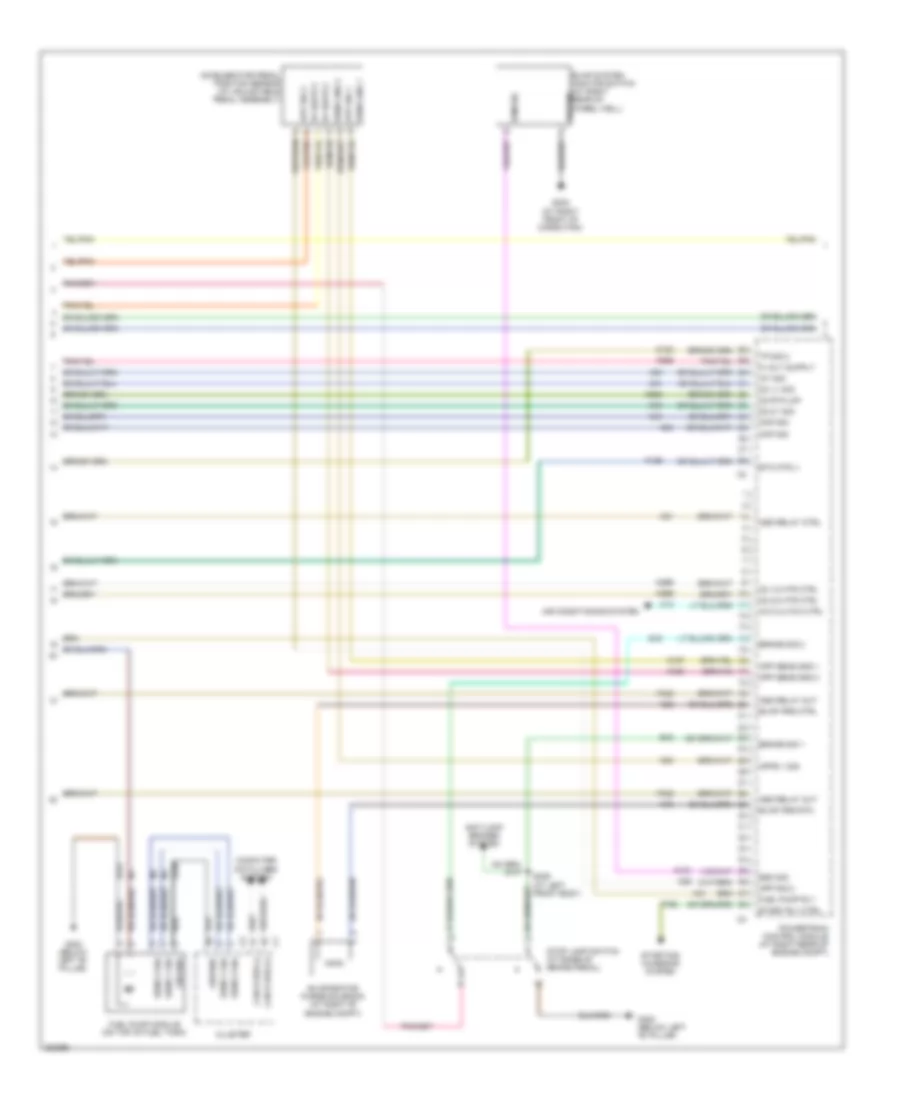
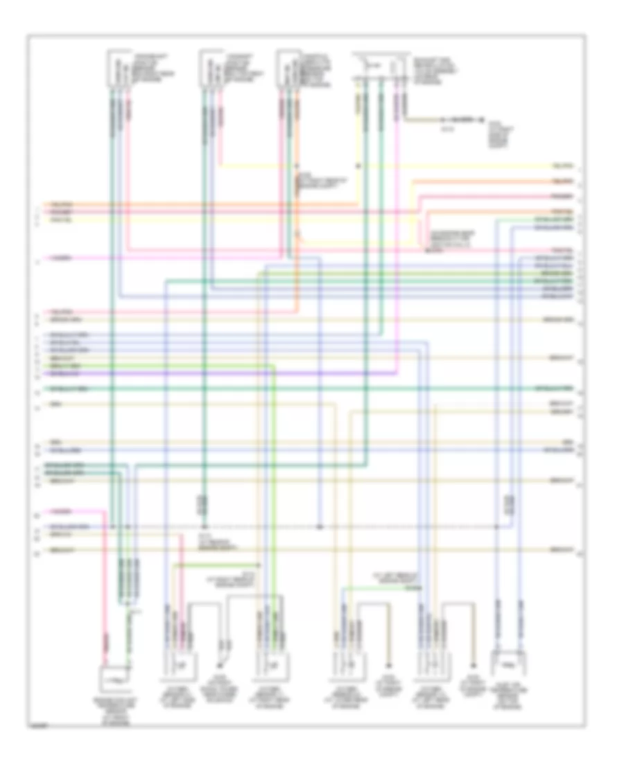
2.7L, Engine Performance Wiring Diagram (1 of 5) for Dodge Charger R/T 2008
 https://portal-diagnostov.com/license.html
Automotive Electricians Portal FZCO
Automotive Electricians Portal FZCO
https://portal-diagnostov.com/license.html
https://portal-diagnostov.com/license.html
Automotive Electricians Portal FZCO
Automotive Electricians Portal FZCOList of elements for 2.7L, Engine Performance Wiring Diagram (1 of 5) for Dodge Charger R/T 2008:
- 87a
- A209
- A804
- Aat sig
- Ambient air temperature sensor (at right front of engine compt)
- Anti-lock brakes module (at right front of engine compt)
- Asd rly out
- Bus (+)
- Bus (-)
- Coil 1 ctrl
- Coil 2 ctrl
- Coil 4 ctrl
- Coil ctrl 3
- Coil ctrl 5
- Coil ctrl 6
- D64
- D65
- Ect sig
- Egr sig
- Egr sol ctrl
- Electronic
- Eop sig
- Etc mtr (+)
- F342
- F856
- F902
- F950
- Fuse 25a
- Fused b(+)
- G102 (at right of engine compt)
- G31
- G931
- Gen field ctrl
- Gen sns
- Ground
- Hot at all times
- Ign off- run- start
- Ign off-run- start
- Inj 1 ctrl
- Inj 2 ctrl
- Inj 3 ctrl
- Inj 4 ctrl
- Inj 5 ctrl
- Inj 6 ctrl
- K10
- K11
- K12
- K124
- K13
- K14
- K141
- K15
- K16
- K17
- K18
- K19
- K199
- K20
- K22
- K243
- K34
- K35
- K38
- K42
- K58
- K900
- K904
- K922
- K942
- K99
- Knock sensor 1 (on rear of engine)
- Ks 1 rtn
- Ks 1 sig
- Map sig
- Nca
- O2 1/1 htr
- O2 1/2 sig
- O2 2/1 htr
- O2 2/2 sig
- O2 rtn (dn)
- Oil pressure switch (on front of engine)
- Pnk
- Powertrain control module (at right rear of engine compt)
- Red
- Right front abs wheel speed sensor (w/ abs) (at right front wheel well)
- Right front wheel speed sensor (w/o abs) (at right front wheel well)
- Run/ start relay
- Run/start rly
- S122 (at right side of engine compt)
- S124 (at right side of engine compt)
- S167
- Sens gnd
- Sens sig
- Sens sply
- Sensor gnd
- Starting/charging system
- Totally integrated power module (at right side of engine compt)
- Tp sens gnd
- Tp sig 1
- Z904
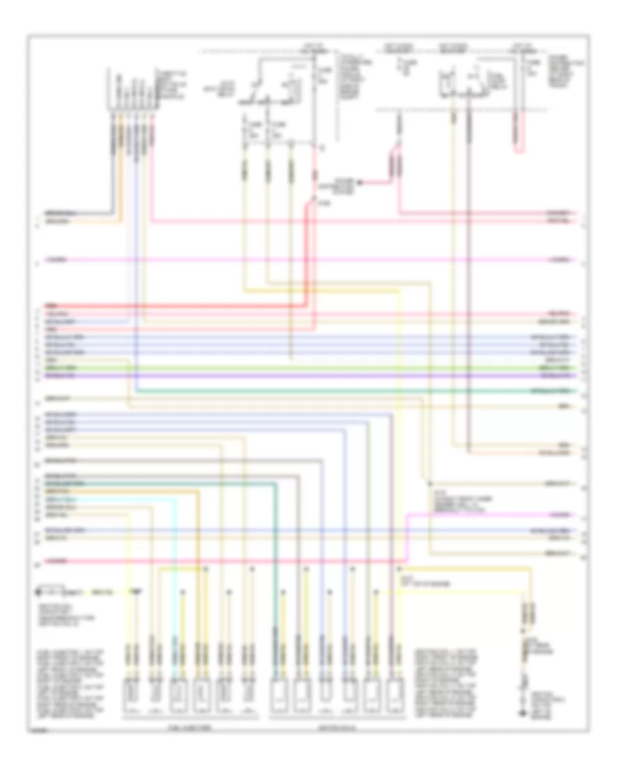
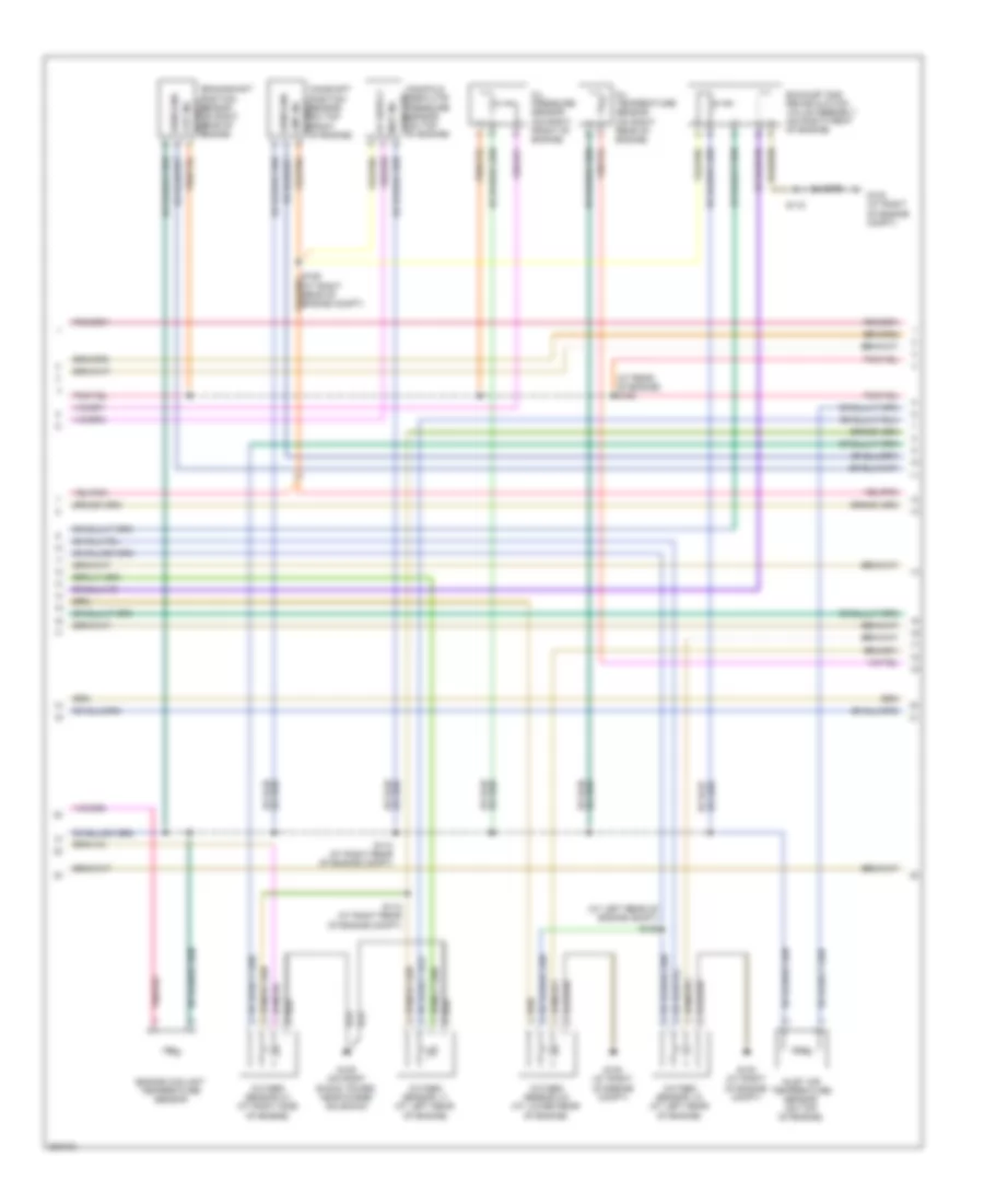
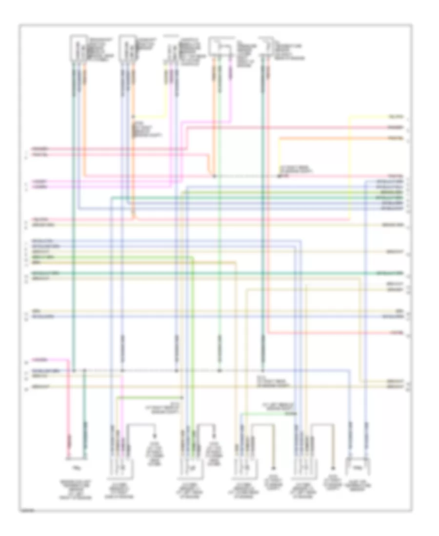
2.7L, Engine Performance Wiring Diagram (2 of 5) for Dodge Charger R/T 2008
 https://portal-diagnostov.com/license.html
Automotive Electricians Portal FZCO
Automotive Electricians Portal FZCO
https://portal-diagnostov.com/license.html
https://portal-diagnostov.com/license.html
Automotive Electricians Portal FZCO
Automotive Electricians Portal FZCOList of elements for 2.7L, Engine Performance Wiring Diagram (2 of 5) for Dodge Charger R/T 2008:
- (fuel injector 1: on top right front of engine) (fuel injector 2: on top left front of engine) (fuel injector 3: on top right of engine) (fuel injector 4: on top left of engine) (fuel injector 5: on top right rear of engine) (fuel injector 6: on top left rear of engine)
- (ignition coil 1: on top right front of engine) (ignition coil 2: on top left rear of engine) (ignition coil 3: on top right of engine) (ignition coil 4: on top left rear of engine) (ignition coil 5: on top right rear of engine) (ignition coil 6: on top left rear of engine)
- 87a
- Auto shut down relay
- Etc mtr (+)
- Etc mtr (-)
- Fuel injectors
- Fuel pump relay
- Fuse 20a
- Fuse 25a
- Fuse 5a
- Hot at all times
- Hot in run or start
- Ignition capacitor 2 (on top left of engine)
- Ignition coil capacitor 1 (near breakout for ignition coil 5)
- Ignition coils
- Nca
- Power distribution center (at right rear of trunk)
- Power distribution system
- Red
- S107 (at top of engine)
- S108 (at rear of engine)
- S109
- S143 (in right front inner fender well, in breakout to c100)
- S166
- Throttle body (on top of intake manifold)
- Totally integrated power module (at right side of engine compt)
- Tp sens gnd
- Tp sig 1
- Tp sig 2
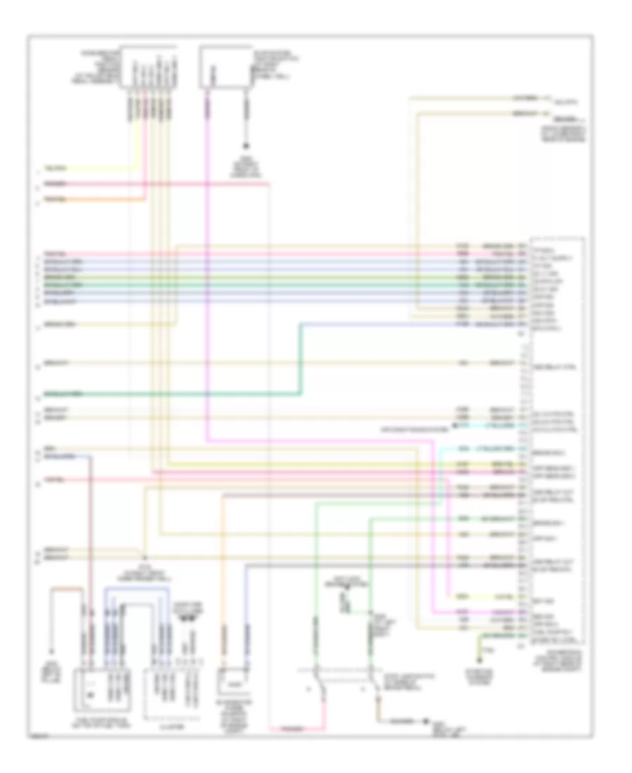
2.7L, Engine Performance Wiring Diagram (3 of 5) for Dodge Charger R/T 2008
 https://portal-diagnostov.com/license.html
Automotive Electricians Portal FZCO
Automotive Electricians Portal FZCO
https://portal-diagnostov.com/license.html
https://portal-diagnostov.com/license.html
Automotive Electricians Portal FZCO
Automotive Electricians Portal FZCOList of elements for 2.7L, Engine Performance Wiring Diagram (3 of 5) for Dodge Charger R/T 2008:
- (at left rear of engine compt)
- (at right rear of engine compt) s105
- Camshaft position sensor (on top front of engine)
- Ckp sig
- Cmp sig
- Crankshaft position sensor (on right rear of engine)
- Engine coolant temperature sensor (at front of engine)
- Exhaust gas recirculation valve assembly (on rear of engine)
- G102 (at right of engine compt)
- G109 (on right shock tower, near purge solenoid)
- Inlet air temperature sensor (on top of engine)
- Map sig
- Oxygen sensor 1/1 (at right rear of engine)
- Oxygen sensor 1/2 (at left rear of engine)
- Oxygen sensor 2/1 (at left side of engine)
- Oxygen sensor 2/2 (at lower rear of engine)
- S106 (at right rear of engine compt)
- S110 (at right rear of engine compt)
- S112 (at right rear of engine compt)
- S115
- S125
- Sens gnd
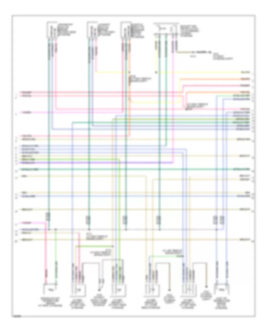
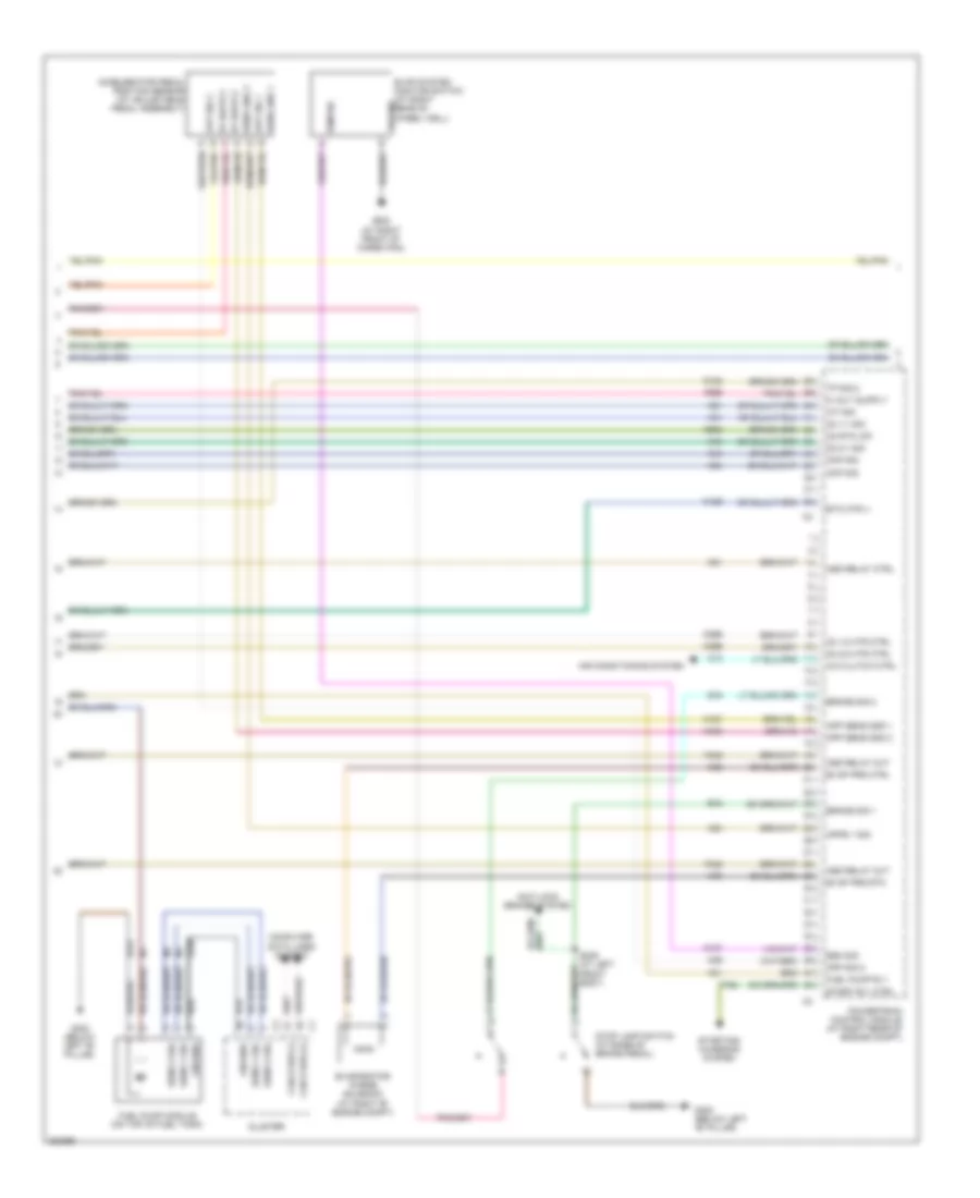
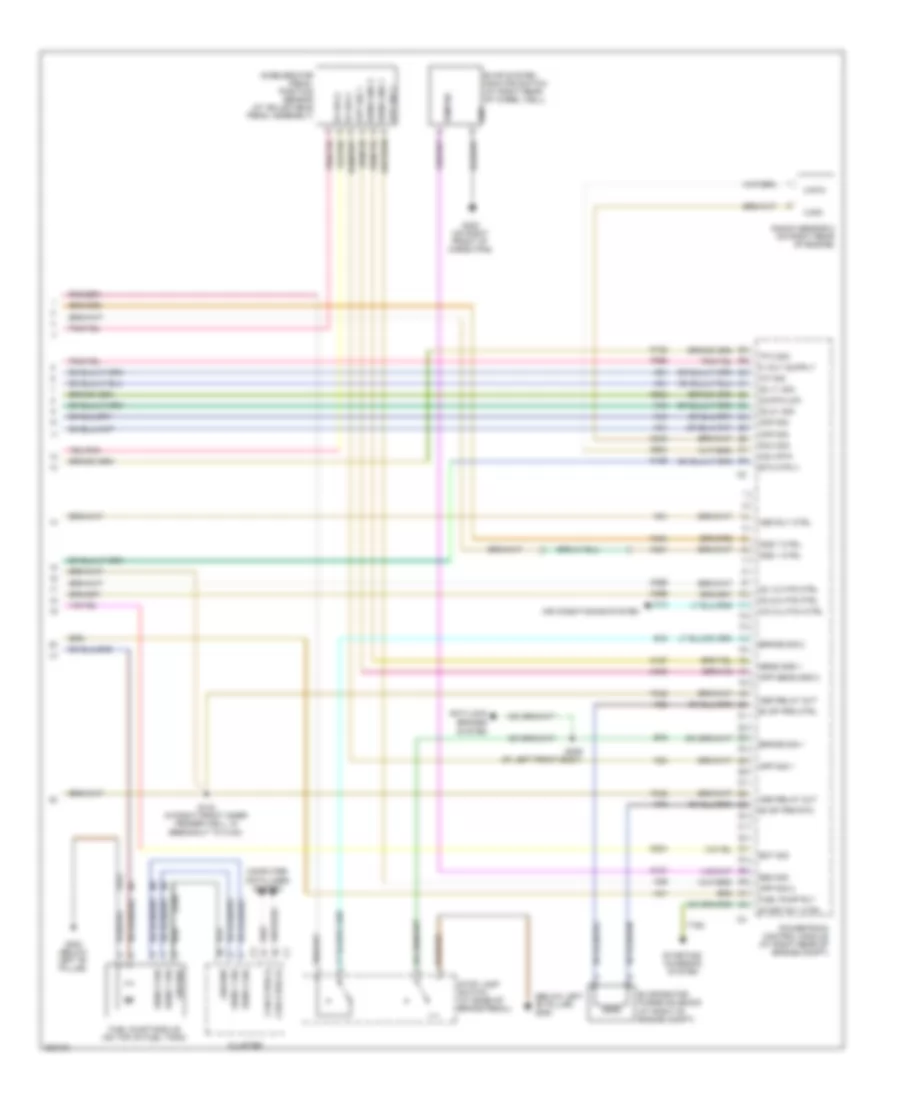
2.7L, Engine Performance Wiring Diagram (4 of 5) for Dodge Charger R/T 2008
 https://portal-diagnostov.com/license.html
Automotive Electricians Portal FZCO
Automotive Electricians Portal FZCO
https://portal-diagnostov.com/license.html
https://portal-diagnostov.com/license.html
Automotive Electricians Portal FZCO
Automotive Electricians Portal FZCOList of elements for 2.7L, Engine Performance Wiring Diagram (4 of 5) for Dodge Charger R/T 2008:
- A/c clutch ctrl
- Accelerator pedal position sensor (at adjustable pedal assembly)
- Air conditioning system
- Anti-lock brakes system
- App sens gnd 1
- App sens gnd 2
- App sig 1
- App sig 2
- Apps 1 sig
- Asd relay ctrl
- Asd relay out
- B15
- B16
- Brake sig 1
- Brake sig 2
- C13
- Can b bus (+)
- Can b bus (-)
- Ckp sig
- Cluster
- Cmp sig
- Computer data lines system
- Esm sig
- Etc mtr (-)
- Evap prg ctrl
- Evap prg rtn
- Evap system monitor switch (at right rear of wheel well)
- Evaporator purge solenoid (at right of engine compt)
- F342
- F855
- Fuel pump module (on top of fuel tank)
- Fuel pump rly
- G300 (below left "b" pillar)
- G302 (at right front of cargo pan)
- Ground
- Iat sig
- K107
- K122
- K126
- K167
- K21
- K23
- K24
- K29
- K299
- K31
- K399
- K400
- K41
- K43
- K44
- K51
- K52
- K70
- K902
- O2 1/1 sig
- O2 1/2 htr ctrl
- O2 2/1 sig
- O2 2/2 htr ctrl
- O2 rtn (up)
- Powertrain control module (at right rear of engine compt)
- S309 (at left front body)
- Sens 1 sig
- Sens 2 sig
- Sens gnd 1
- Sens gnd 2
- Start rly ctrl
- Starting/ charging system
- Stop lamp switch (at base of brake pedal)
- T752
- Tp sig 2
- Z210
- Z912
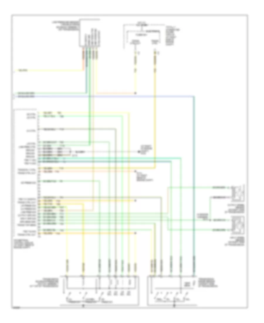
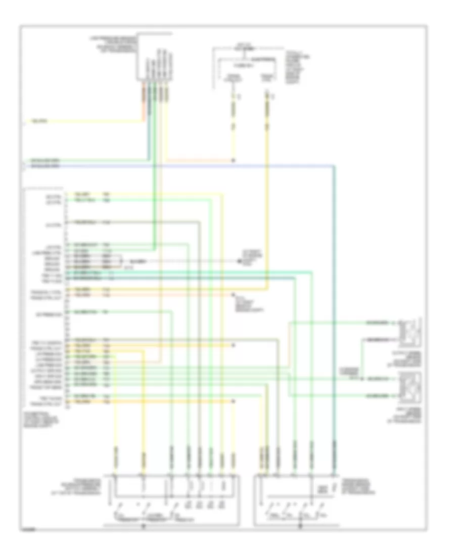
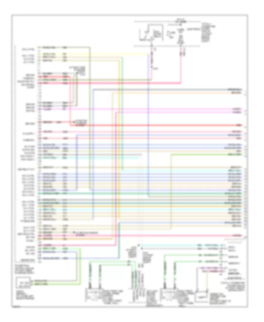
2.7L, Engine Performance Wiring Diagram (5 of 5) for Dodge Charger R/T 2008
 https://portal-diagnostov.com/license.html
Automotive Electricians Portal FZCO
Automotive Electricians Portal FZCO
https://portal-diagnostov.com/license.html
https://portal-diagnostov.com/license.html
Automotive Electricians Portal FZCO
Automotive Electricians Portal FZCOList of elements for 2.7L, Engine Performance Wiring Diagram (5 of 5) for Dodge Charger R/T 2008:
- (at right of engine compt) g102
- (in engine harness) s113
- 2/4 ctrl
- 2/4 press sig
- 2/4 press sw
- 2/4 sol
- Ctrl output
- Electronic
- Fused b(+)
- Ground
- Hot at all times
- Input spd sig
- Input speed sensor (on right side of transmission)
- L/r ctrl
- L/r press sig
- L/r sol
- Line pres ctrl
- Line pres sig
- Line press sig
- Line pressure sensor/ variable force solenoid assembly (on transmission)
- Low/rev press sw
- Nol
- Od ctrl
- Od press sig
- Od press sw
- Od sol
- Output spd sig
- Output speed sensor (on right side of transmission)
- P3l
- Powertrain control module (at right rear of engine compt)
- Prnl
- S114 (at right rear of engine compt)
- S115
- Sens gnd
- Spd sens gnd
- T118
- T13
- T14
- T15
- T16
- T19
- T20
- T38
- T41
- T42
- T47
- T50
- T52
- T54
- T59
- T60
- Temp sens
- Totally integrated power module (at right side of engine compt)
- Trans ctrl
- Trans ctrl out
- Trans rly ctrl
- Trans tmp sens
- Transmission range sensor (on right side of transmission)
- Transmission solenoid/pressure switch assembly (at top of transmission)
- Trs t1 sig
- Trs t3 sig
- Trs t41 sig(p/n)
- Trs t42 sig
- Ud ctrl
- Ud sol
- Z904
3.5L
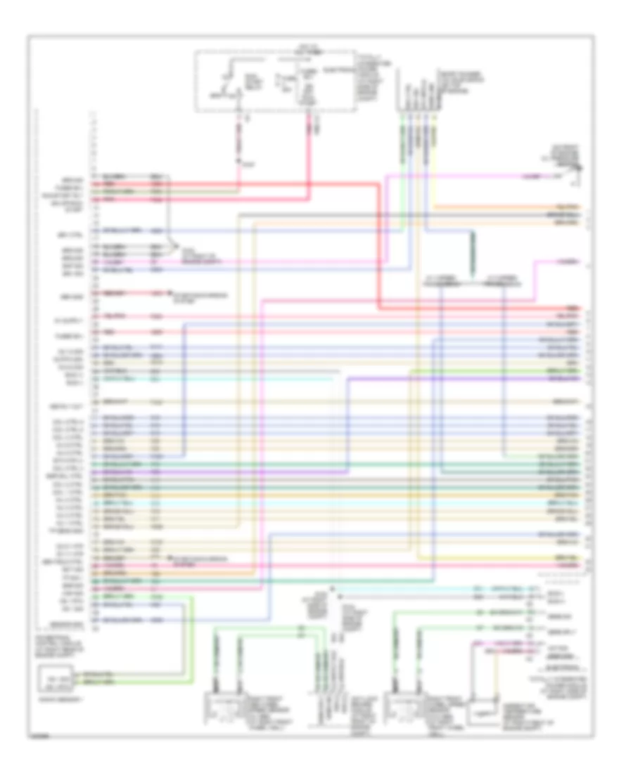
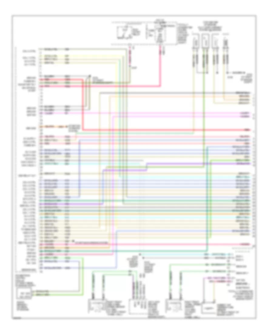
3.5L, Engine Performance Wiring Diagram (1 of 5) for Dodge Charger R/T 2008
 https://portal-diagnostov.com/license.html
Automotive Electricians Portal FZCO
Automotive Electricians Portal FZCO
https://portal-diagnostov.com/license.html
https://portal-diagnostov.com/license.html
Automotive Electricians Portal FZCO
Automotive Electricians Portal FZCOList of elements for 3.5L, Engine Performance Wiring Diagram (1 of 5) for Dodge Charger R/T 2008:
- (on front of engine) oil pressure switch
- 5v sply
- 87a
- A209
- A804
- Aat sig
- Ambient air temperature sensor (at right front of engine compt)
- Anti-lock brakes module (at right front of engine compt)
- Asd rly out
- Bus (+)
- Bus (-)
- Coil 1 ctrl
- Coil 2 ctrl
- Coil 4 ctrl
- Coil ctrl 3
- Coil ctrl 5
- Coil ctrl 6
- D64
- D65
- Ect sig
- Egr sig
- Egr sol ctrl
- Electronic
- Eop sig
- Etc mtr (+)
- F342
- F856
- F902
- F950
- Fuse 25a
- Fused b(+)
- G102 (at right of engine compt)
- G31
- G931
- Gen field ctrl
- Gen sns
- Ground
- Hot at all times
- Ign off- run- start
- Ign off-run- start
- Inj 1 ctrl
- Inj 2 ctrl
- Inj 3 ctrl
- Inj 4 ctrl
- Inj 5 ctrl
- Inj 6 ctrl
- K10
- K11
- K12
- K124
- K13
- K14
- K141
- K15
- K16
- K17
- K18
- K19
- K199
- K20
- K22
- K235
- K236
- K243
- K34
- K35
- K38
- K42
- K58
- K900
- K904
- K922
- K942
- K99
- Knock sensor 1
- Ks 1 rtn
- Ks 1 sig
- Map sig
- Nca
- O2 1/1 htr
- O2 1/2 sig
- O2 2/1 htr
- O2 2/2 sig
- O2 rtn (dn)
- Pnk
- Powertrain control module (at right rear of engine compt)
- Red
- Right front abs wheel speed sensor (w/ abs) (at right front wheel well)
- Right front wheel speed sensor (w/o abs) (at right front wheel well)
- Run/ start relay
- Run/start rly
- S122 (at right side of engine compt)
- S124 (at right side of engine compt)
- S167
- Sens gnd
- Sens sig
- Sens sply
- Sensor gnd
- Short runner valve solenoid (on top of engine)
- Srv ctrl
- Srv sig
- Starting/charging system
- Totally integrated power module (at right side of engine compt)
- Tp sens gnd
- Tp sig 1
- W/ 4 speed transmission
- W/ 5 speed transmission
- Z904
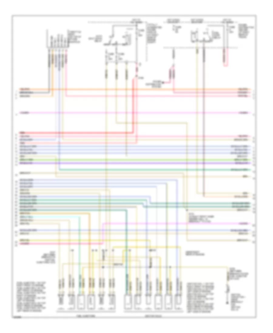
3.5L, Engine Performance Wiring Diagram (2 of 5) for Dodge Charger R/T 2008
 https://portal-diagnostov.com/license.html
Automotive Electricians Portal FZCO
Automotive Electricians Portal FZCO
https://portal-diagnostov.com/license.html
https://portal-diagnostov.com/license.html
Automotive Electricians Portal FZCO
Automotive Electricians Portal FZCOList of elements for 3.5L, Engine Performance Wiring Diagram (2 of 5) for Dodge Charger R/T 2008:
- (fuel injector 1: on top right front of engine) (fuel injector 2: on top left front of engine) (fuel injector 3: on top right of engine) (fuel injector 4: on top left of engine) (fuel injector 5: on top right rear of engine) (fuel injector 6: on top left rear of engine)
- (ignition coil 1: on top right front of engine) (ignition coil 2: on top left side of engine) (ignition coil 3: on top right of engine) (ignition coil 4: on top left of engine) (ignition coil 5: on top right rear of engine) (ignition coil 6: on top left side of engine)
- (near right rear of engine)
- 5v sply
- 87a
- Auto shut down relay
- Etc mtr (+)
- Etc mtr (-)
- Fuel injectors
- Fuel pump relay
- Fuse 20a
- Fuse 25a
- Fuse 5a
- Hot at all times
- Hot in run or start
- Ignition capacitor 1 (near breakout for ignition coil 5)
- Ignition coils
- Nca
- Power distribution center (at right rear of trunk)
- Power distribution system
- Red
- S107 (between breakouts for fuel injectors 3 & 5)
- S108 (between breakouts for fuel injector no 4 & 6)
- S109
- S143 (in right front inner fender well, in breakout to c100)
- S166
- Sens gnd
- Throttle body (on top of intake manifold)
- Totally integrated power module (at right side of engine compt)
- Tp sig 1
- Tp sig 2
3.5L, Engine Performance Wiring Diagram (3 of 5) for Dodge Charger R/T 2008
 https://portal-diagnostov.com/license.html
Automotive Electricians Portal FZCO
Automotive Electricians Portal FZCO
https://portal-diagnostov.com/license.html
https://portal-diagnostov.com/license.html
Automotive Electricians Portal FZCO
Automotive Electricians Portal FZCOList of elements for 3.5L, Engine Performance Wiring Diagram (3 of 5) for Dodge Charger R/T 2008:
- (at left rear of engine compt)
- (on engine near breakout for ignition coil 5) s105
- 5v sply
- Camshaft position sensor (on top front of engine)
- Ckp sig
- Cmp sig
- Crankshaft position sensor (on right rear of engine)
- Engine coolant temperature sensor (at front of engine)
- Exhaust gas recirculation valve assembly (on rear of engine)
- G102 (at right of engine compt)
- G102 (at right side of engine compt)
- G109 (on right shock tower, near purge solenoid)
- Inlet air temperature sensor (on top of engine)
- Manifold absolute pressure sensor (on top of engine) 5v sply
- Map sig
- Oxygen sensor 1/1 (at right rear of engine)
- Oxygen sensor 1/2 (at left rear of engine)
- Oxygen sensor 2/1 (at left side of engine)
- Oxygen sensor 2/2 (at lower rear of engine)
- S106 (at right rear of engine compt)
- S110 (at rear of engine compt)
- S111
- S112 (at right rear of engine compt)
- S115
- S125
- Sens gnd
3.5L, Engine Performance Wiring Diagram (4 of 5) for Dodge Charger R/T 2008
 https://portal-diagnostov.com/license.html
Automotive Electricians Portal FZCO
Automotive Electricians Portal FZCO
https://portal-diagnostov.com/license.html
https://portal-diagnostov.com/license.html
Automotive Electricians Portal FZCO
Automotive Electricians Portal FZCOList of elements for 3.5L, Engine Performance Wiring Diagram (4 of 5) for Dodge Charger R/T 2008:
- A/c clutch ctrl
- Accelerator pedal position sensor (at adjustable pedal assembly)
- Air conditioning system
- Anti-lock brakes system
- App sens gnd 1
- App sens gnd 2
- App sig 1
- App sig 2
- Apps 1 sig
- Asd relay ctrl
- Asd relay out
- B15
- B16
- Brake sig 1
- Brake sig 2
- C13
- Can b bus (+)
- Can b bus (-)
- Ckp sig
- Cluster
- Cmp sig
- Computer data lines system
- Esm sig
- Etc mtr (-)
- Evap prg ctrl
- Evap prg rtn
- Evap system monitor switch (at right rear of wheel well)
- Evaporator purge solenoid (at right of engine compt)
- F342
- F855
- Fuel pump module (on top of fuel tank)
- Fuel pump rly
- G300 (below left "b" pillar)
- G302 (at right front of cargo pan)
- Ground
- Iat sig
- K107
- K122
- K126
- K167
- K21
- K23
- K24
- K29
- K299
- K31
- K399
- K400
- K41
- K43
- K44
- K51
- K52
- K70
- K902
- O2 1/1 sig
- O2 1/2 htr ctrl
- O2 2/1 sig
- O2 2/2 htr ctrl
- O2 rtn (up)
- Powertrain control module (at right rear of engine compt)
- S309 (at left front body)
- Sens 1 sig
- Sens 2 sig
- Sens gnd 1
- Sens gnd 2
- Start rly ctrl
- Starting/ charging system
- Stop lamp switch (at base of brake pedal)
- T752
- Tp sig 2
- Z210
- Z912
3.5L, Engine Performance Wiring Diagram (5 of 5) for Dodge Charger R/T 2008
 https://portal-diagnostov.com/license.html
Automotive Electricians Portal FZCO
Automotive Electricians Portal FZCO
https://portal-diagnostov.com/license.html
https://portal-diagnostov.com/license.html
Automotive Electricians Portal FZCO
Automotive Electricians Portal FZCOList of elements for 3.5L, Engine Performance Wiring Diagram (5 of 5) for Dodge Charger R/T 2008:
- (at right of engine compt) g102
- (in engine harness) s113
- 2/4 ctrl
- 2/4 press sig
- 2/4 press sw
- 2/4 sol
- Ctrl output
- Electronic
- Fused b(+)
- Ground
- Hot at all times
- Input spd sig
- Input speed sensor (on right side of transmission)
- L/r ctrl
- L/r press sig
- L/r sol
- Line pres ctrl
- Line pres sig
- Line press sig
- Line pressure sensor/ variable force solenoid assembly (on transmission)
- Low/rev press sw
- Nol
- Od ctrl
- Od press sig
- Od press sw
- Od sol
- Output spd sig
- Output speed sensor (on right side of transmission)
- P3l
- Powertrain control module (at right rear of engine compt)
- Prnl
- S114 (at right rear of engine compt)
- S115
- Sens gnd
- Spd sens gnd
- T118
- T13
- T14
- T15
- T16
- T19
- T20
- T38
- T41
- T42
- T47
- T50
- T52
- T54
- T59
- T60
- Temp sens
- Totally integrated power module (at right side of engine compt)
- Trans ctrl
- Trans ctrl out
- Trans rly ctrl
- Trans tmp sens
- Transmission range sensor (on right side of transmission)
- Transmission solenoid/pressure switch assembly (at top of transmission)
- Trs t1 sig
- Trs t3 sig
- Trs t41 sig(p/n)
- Trs t42 sig
- Ud ctrl
- Ud sol
- Z904
5.7L
5.7L, Engine Performance Wiring Diagram (1 of 4) for Dodge Charger R/T 2008
 https://portal-diagnostov.com/license.html
Automotive Electricians Portal FZCO
Automotive Electricians Portal FZCO
https://portal-diagnostov.com/license.html
https://portal-diagnostov.com/license.html
Automotive Electricians Portal FZCO
Automotive Electricians Portal FZCOList of elements for 5.7L, Engine Performance Wiring Diagram (1 of 4) for Dodge Charger R/T 2008:
- (top center of engine) multi displacement system solenoids
- 87a
- A209
- A804
- Aat sig
- Ambient air temperature sensor (at right front of engine compt)
- Anti-lock brakes module (w/ esp) (at right front of engine compt)
- Asd relay out
- Bus (+)
- Bus (-)
- Can c bus (+)
- Can c bus (-)
- Coil 1 ctrl
- Coil 2 ctrl
- Coil 3 ctrl
- Coil 4 ctrl
- Coil 5 ctrl
- Coil 6 ctrl
- Coil 7 ctrl
- Coil 8 ctrl
- D64
- D65
- Ect sig
- Egr sig
- Egr sol ctrl
- Electronic
- Eop sig
- Etc mtr (+)
- F342
- F856
- F902
- F950
- Fuse 25a
- Fused b(+)
- G102 (at right of engine compt)
- G31
- G931
- Gen field ctrl
- Gen sns
- Ground
- Hot at all times
- Ign off- run- start
- Ign off-run- start
- Inj 1 cntrl
- Inj 2 ctrl
- Inj 3 ctrl
- Inj 4 ctrl
- Inj 5 ctrl
- Inj 6 ctrl
- Inj 7 ctrl
- Inj 8 ctrl
- K10
- K11
- K12
- K124
- K13
- K14
- K141
- K15
- K16
- K17
- K18
- K19
- K199
- K20
- K22
- K243
- K26
- K28
- K34
- K35
- K38
- K42
- K452
- K453
- K58
- K900
- K904
- K922
- K942
- K97
- K98
- K99
- Knock sensor 1 (on rear of engine)
- Ks 1 rtn
- Ks 1 sig
- Map sig
- Mds 4 ctrl
- Mds 6 ctrl
- Nca
- O2 1/1 htr
- O2 1/2 sig
- O2 2/1 htr
- O2 2/2 sig
- O2 rtn (dn)
- Pnk
- Powertrain control module (at right rear of engine compt)
- Red
- Right front abs wheel speed sensor (w/ abs) (at right front wheel well)
- Right front wheel speed sensor (w/o abs) (at right front wheel well)
- Run/ start relay
- Run/start rly
- S122 (at right side of engine compt)
- S124 (at right side of engine compt)
- S136
- S167
- Sens gnd
- Sens sig
- Sens sply
- Sensor gnd
- Sig
- Sply
- Starting/ charging system
- Starting/charging system
- Totally integrated power module (at right side of engine compt)
- Tp sens gnd
- Tp sig 1
- Z904
5.7L, Engine Performance Wiring Diagram (2 of 4) for Dodge Charger R/T 2008
 https://portal-diagnostov.com/license.html
Automotive Electricians Portal FZCO
Automotive Electricians Portal FZCO
https://portal-diagnostov.com/license.html
https://portal-diagnostov.com/license.html
Automotive Electricians Portal FZCO
Automotive Electricians Portal FZCOList of elements for 5.7L, Engine Performance Wiring Diagram (2 of 4) for Dodge Charger R/T 2008:
- (fuel injector 1: on top left front of engine) (fuel injector 2: on top right front of engine) (fuel injector 3: on top left of engine) (fuel injector 4: on top right of engine) (fuel injectors 5 & 7: on top left rear of engine) (fuel injectors 6 & 8: on top right rear of engine)
- (ignition coil 1: on top left rear of engine) (ignition coil 2: on top right rear of engine) (ignition coil 3: on top left rear of engine) (ignition coil 4: on top right of engine) (ignition coils 5 & 7: on top left rear of engine) (ignition coils 6 & 8: on top right rear of engine)
- 5v sply
- 87a
- Auto shut down relay
- Etc mtr (+)
- Etc mtr (-)
- Fuel injectors
- Fuel pump relay
- Fuse 20a
- Fuse 25a
- Fuse 5a
- Hot at all times
- Hot in run or start
- Ignition coil
- Ignition coil capacitor 2
- Nca
- Power distribution center (at right rear of trunk)
- Power distribution system
- Red
- S107 (on top of engine)
- S108 (at top of engine between fuel injectors 5 & 7)
- S109 (at right rear of engine)
- S166
- Sens gnd
- Throttle body (on top of intake manifold)
- Totally integrated power module (at right side of engine compt)
- Tp 1 sig
- Tp 2 sig
5.7L, Engine Performance Wiring Diagram (3 of 4) for Dodge Charger R/T 2008
 https://portal-diagnostov.com/license.html
Automotive Electricians Portal FZCO
Automotive Electricians Portal FZCO
https://portal-diagnostov.com/license.html
https://portal-diagnostov.com/license.html
Automotive Electricians Portal FZCO
Automotive Electricians Portal FZCOList of elements for 5.7L, Engine Performance Wiring Diagram (3 of 4) for Dodge Charger R/T 2008:
- (at left rear of engine compt)
- (at rear of engine) s105
- Camshaft position sensor (on top front of engine) 5v sply
- Ckp sig
- Cmp sig
- Crankshaft position sensor (on right rear of engine) 5v sply
- Engine coolant temperature sensor
- Exhaust gas recirculation valve assembly (on right front of engine)
- G102 (at right of engine compt)
- G109 (on right shock tower, near purge solenoid)
- Inlet air temperature sensor (on top of engine)
- Manifold absolute pressure sensor (on top of engine) sens gnd
- Map sig
- Oil pressure sensor (on right front of engine)
- Oil temperature sensor (on right rear of engine)
- Oxygen sensor 1/1 (at left rear of engine)
- Oxygen sensor 1/2 (at left rear of engine)
- Oxygen sensor 2/1 (at right side of engine)
- Oxygen sensor 2/2 (at lower rear of engine)
- S106 (at right rear of engine compt)
- S110 (at right rear of engine compt)
- S112 (at right rear of engine compt)
- S115
- S125
- Sens gnd
5.7L, Engine Performance Wiring Diagram (4 of 4) for Dodge Charger R/T 2008
 https://portal-diagnostov.com/license.html
Automotive Electricians Portal FZCO
Automotive Electricians Portal FZCO
https://portal-diagnostov.com/license.html
https://portal-diagnostov.com/license.html
Automotive Electricians Portal FZCO
Automotive Electricians Portal FZCOList of elements for 5.7L, Engine Performance Wiring Diagram (4 of 4) for Dodge Charger R/T 2008:
- (below left "b" pillar) g300
- 2 rtn
- 2 sig
- 5v sply
- A/c clutch ctrl
- Accelerator pedal position sensor (at adjustable pedal assembly)
- Air conditioning system
- Anti-lock brakes
- App sens gnd 2
- App sig 1
- App sig 2
- Asd relay out
- Asd rly ctrl
- B15
- B16
- Brake sig 1
- Brake sig 2
- C13
- Can b bus (+)
- Can b bus (-)
- Ckp sig
- Cluster
- Cmp sig
- Computer data lines system
- Eot sig
- Esm sig
- Etc mtr (-)
- Evap prg ctrl
- Evap prg rtn
- Evap system monitor switch (at right rear of wheel well)
- Evaporator purge solenoid (at right of engine compt)
- F342
- F855
- Fuel pump module (on top of fuel tank)
- Fuel pump rly
- G224
- G300 (below left "b" pillar)
- G302 (on right front of cargo pan)
- Gnd
- Ground
- Iat sig
- K107
- K122
- K126
- K167
- K21
- K23
- K24
- K242
- K29
- K299
- K31
- K399
- K400
- K41
- K43
- K44
- K451
- K454
- K51
- K52
- K70
- K902
- K924
- Knock sensor 2 (on right rear of engine)
- Ks 2 rtn
- Ks 2 sig
- Mds 1 ctrl
- Mds 7 ctrl
- O2 1/1 sig
- O2 1/2 htr ctrl
- O2 2/1 sig
- O2 2/2 htr ctrl
- O2 rtn (up)
- Powertrain control module (at right rear of engine compt)
- S143 (in right front inner fender well, in breakout to c100)
- S309 (at left front body)
- Sens 1 sig
- Sens 2 sig
- Sens gnd 1
- Sens gnd 2
- Start rly ctrl
- Starting/ charging system
- Stop lamp switch (at base of brake pedal)
- System
- T752
- Tp 2 sig
- Z210
- Z912
6.1L
6.1L, Engine Performance Wiring Diagram (1 of 4) for Dodge Charger R/T 2008
 https://portal-diagnostov.com/license.html
Automotive Electricians Portal FZCO
Automotive Electricians Portal FZCO
https://portal-diagnostov.com/license.html
https://portal-diagnostov.com/license.html
Automotive Electricians Portal FZCO
Automotive Electricians Portal FZCOList of elements for 6.1L, Engine Performance Wiring Diagram (1 of 4) for Dodge Charger R/T 2008:
- (at right side of engine compt) g102
- 87a
- A209
- A804
- Aat sig
- Ambient air temperature sensor (at right front of engine compt)
- Anti-lock brakes module (w/ esp) (at right front of engine compt)
- Asd relay out
- Bus (+)
- Bus (-)
- Can c bus (+)
- Can c bus (-)
- Coil 1 ctrl
- Coil 2 ctrl
- Coil 3 ctrl
- Coil 4 ctrl
- Coil 5 ctrl
- Coil 6 ctrl
- Coil 7 ctrl
- Coil 8 ctrl
- D64
- D65
- Ect sig
- Electronic
- Eop sig
- Etc mtr (+)
- F342
- F856
- F902
- F950
- Fuse 25a
- Fused b(+)
- G31
- G931
- Gen field ctrl
- Gen sns
- Ground
- Hot at all times
- Ign off- run- start
- Ign off-run- start
- Inj 1 ctrl
- Inj 2 ctrl
- Inj 3 ctrl
- Inj 4 ctrl
- Inj 5 ctrl
- Inj 6 ctrl
- Inj 7 ctrl
- Inj 8 ctrl
- K10
- K11
- K12
- K124
- K13
- K14
- K141
- K15
- K16
- K17
- K18
- K19
- K199
- K20
- K22
- K243
- K26
- K28
- K38
- K42
- K58
- K900
- K904
- K922
- K942
- K97
- K98
- K99
- Knock sensor 1 (at lower left rear of engine)
- Ks 1 rtn
- Ks 1 sig
- Map sig
- Nca
- O2 1/1 htr
- O2 1/2 sig
- O2 2/1 htr
- O2 2/2 sig
- O2 rtn (dn)
- Pnk
- Powertrain control module (at right rear of engine compt)
- Red
- Right front abs wheel speed sensor (w/ abs) (at right front wheel well)
- Right front wheel speed sensor (w/o abs) (at right front wheel well)
- Run/ start relay
- Run/start rly
- S122 (at right side of engine compt)
- S124 (at right side of engine compt)
- S167
- Sens gnd
- Sens sig
- Sens sply
- Sensor gnd
- Starting/ charging system
- Starting/charging system
- Totally integrated power module (at right side of engine compt)
- Tp sens gnd
- Tp sig 1
- Z904
6.1L, Engine Performance Wiring Diagram (2 of 4) for Dodge Charger R/T 2008
 https://portal-diagnostov.com/license.html
Automotive Electricians Portal FZCO
Automotive Electricians Portal FZCO
https://portal-diagnostov.com/license.html
https://portal-diagnostov.com/license.html
Automotive Electricians Portal FZCO
Automotive Electricians Portal FZCOList of elements for 6.1L, Engine Performance Wiring Diagram (2 of 4) for Dodge Charger R/T 2008:
- (at rear of left engine head) ignition coil capacitor 1
- (fuel injector 1: at left side of intake manifold) (fuel injector 2: on top right rear of engine) (fuel injector 3: at left side of intake manifold) (fuel injector 4: at top right rear of engine) (fuel injector 5 & 7: at left side of intake manifold) (fuel injectors 6 : at top right rear of engine) (fuel injectors 8: on top right rear of engine)
- (ignition coil 1: on top right rear of engine) (ignition coil 2: on top right rear of engine) (ignition coil 3: on right rear of engine) (ignition coil 4: on top right rear of engine) (ignition coil 5: on right rear of engine) (ignition coil 7: on top right rear of engine) (ignition coils 6 & 8: on top right rear of engine)
- 5v sply
- 87a
- Auto shut down relay
- Etc mtr (+)
- Etc mtr (-)
- Fuel injectors
- Fuel pump relay
- Fuse 20a
- Fuse 25a
- Fuse 5a
- Hot at all times
- Hot in run or start
- Ignition coils
- Power distribution center (at right rear of trunk)
- Power distribution system
- Red
- S107 (at rear of engine)
- S108 (at right rear top of engine, next to ignition coil 8)
- S109 (at right rear of engine)
- S166
- Throttle body (at top of intake manifold)
- Totally integrated power module (at right side of engine compt)
- Tp sens gnd
- Tp sig 1
- Tp sig 2
6.1L, Engine Performance Wiring Diagram (3 of 4) for Dodge Charger R/T 2008
 https://portal-diagnostov.com/license.html
Automotive Electricians Portal FZCO
Automotive Electricians Portal FZCO
https://portal-diagnostov.com/license.html
https://portal-diagnostov.com/license.html
Automotive Electricians Portal FZCO
Automotive Electricians Portal FZCOList of elements for 6.1L, Engine Performance Wiring Diagram (3 of 4) for Dodge Charger R/T 2008:
- (at left rear of engine compt)
- (at right rear of engine compt) s105
- 5v sply
- Camshaft position sensor
- Ckp sig
- Cmp sig
- Crankshaft position sensor (rear of engine, near flywheel) 5v sply
- Engine coolant temperature sensor (at left front of engine)
- G102 (at right of engine compt)
- G109 (at top of right cylinder head cover)
- Inlet air temperature sensor
- Manifold absolute pressure sensor (at top rear of intake sens gnd manifold)
- Map sig
- Oil pressure sensor (lower right front of engine)
- Oil temperature sensor (on right rear of engine)
- Oxygen sensor 1/1 (at left rear of engine)
- Oxygen sensor 1/2 (at left rear of engine)
- Oxygen sensor 2/1 (at right side of engine)
- Oxygen sensor 2/2 (at lower rear of engine)
- S106 (at right rear of engine compt)
- S110 (at right rear of engine compt)
- S112 (at right rear of engine compt)
- S125
- Sens gnd
6.1L, Engine Performance Wiring Diagram (4 of 4) for Dodge Charger R/T 2008
 https://portal-diagnostov.com/license.html
Automotive Electricians Portal FZCO
Automotive Electricians Portal FZCO
https://portal-diagnostov.com/license.html
https://portal-diagnostov.com/license.html
Automotive Electricians Portal FZCO
Automotive Electricians Portal FZCOList of elements for 6.1L, Engine Performance Wiring Diagram (4 of 4) for Dodge Charger R/T 2008:
- 5v sply
- A/c clutch ctrl
- Accelerator pedal position sensor (at adjustable pedal assembly)
- Air conditioning system
- Anti-lock brakes system
- App sens gnd 1
- App sens gnd 2
- App sig 1
- App sig 2
- Asd relay ctrl
- Asd relay out
- B15
- B16
- Brake sig 1
- Brake sig 2
- C13
- Can b bus (+)
- Can b bus (-)
- Ckp sig
- Cluster
- Cmp sig
- Computer data lines system
- Eot sig
- Esm sig
- Etc mtr (-)
- Evap prg ctrl
- Evap prg rtn
- Evap system monitor switch (at right rear of wheel well)
- Evaporator purge solenoid (at right of engine compt)
- F342
- F855
- Fuel pump module (on top of fuel tank)
- Fuel pump rly
- G224
- G300 (below left "b" pillar)
- G302 (on right front of cargo pan)
- Ground
- Iat sig
- K107
- K122
- K126
- K167
- K21
- K23
- K24
- K242
- K29
- K299
- K31
- K399
- K400
- K41
- K43
- K44
- K51
- K52
- K70
- K902
- K924
- Knock sensor 2 (at lower right rear of engine)
- Ks 2 rtn
- Ks 2 sig
- O2 1/1 sig
- O2 1/2 htr ctrl
- O2 2/1 sig
- O2 2/2 htr ctrl
- O2 rtn (up)
- Powertrain control module (at right rear of engine compt)
- S143 (in right front inner fender well)
- S309 (at left front body)
- Sens 1 sig
- Sens 2 sig
- Sens gnd 1
- Sens gnd 2
- Start rly ctrl
- Starting/ charging system
- Stop lamp switch (at base of brake pedal)
- T752
- Tp sig 2
- Z210
- Z912
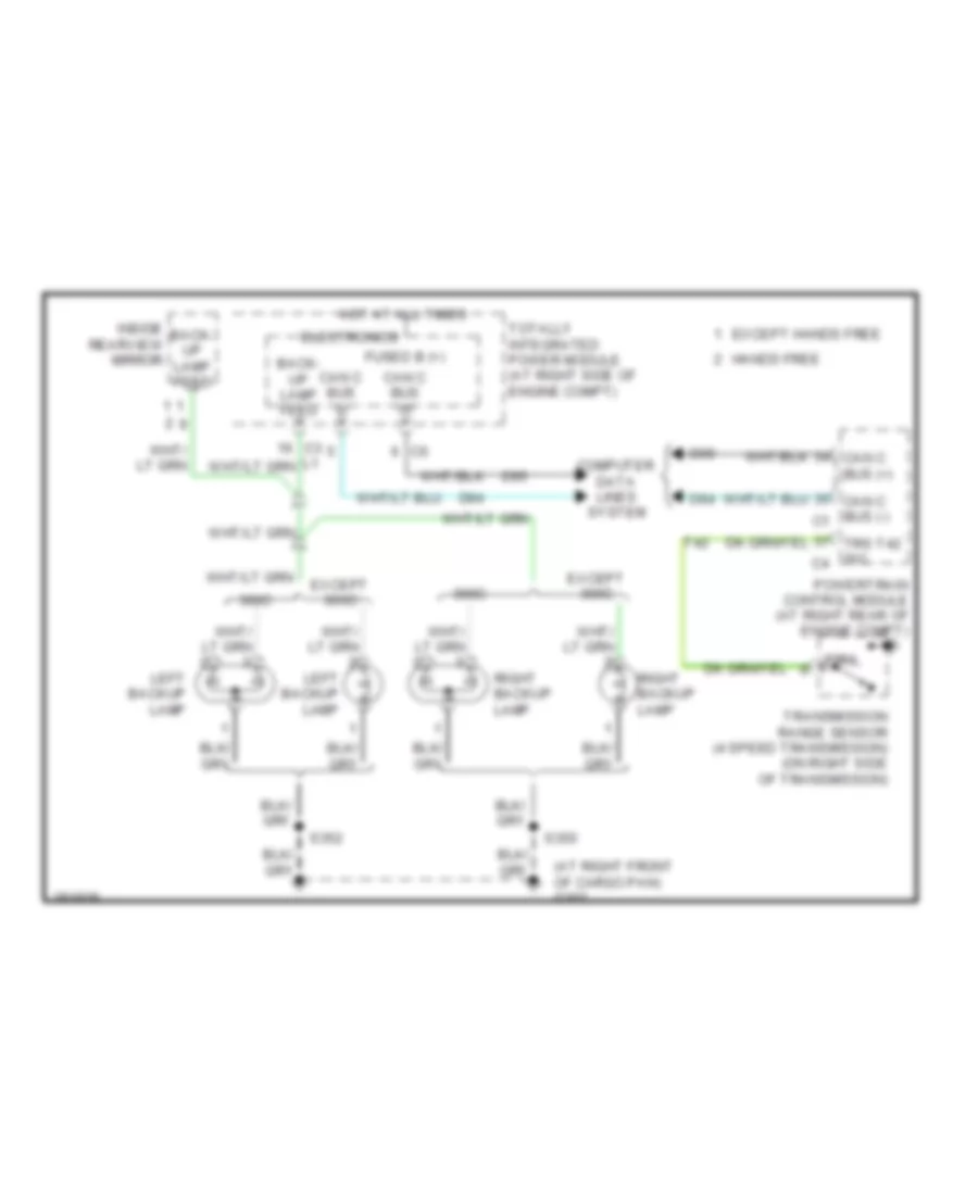
EXTERIOR LIGHTS
Backup Lamps Wiring Diagram for Dodge Charger R/T 2008
 https://portal-diagnostov.com/license.html
Automotive Electricians Portal FZCO
Automotive Electricians Portal FZCO
https://portal-diagnostov.com/license.html
https://portal-diagnostov.com/license.html
Automotive Electricians Portal FZCO
Automotive Electricians Portal FZCOList of elements for Backup Lamps Wiring Diagram for Dodge Charger R/T 2008:
- (at right front of cargo pan) g302
- 300c
- Back- up lamp feed
- Can c bus (+)
- Can c bus (-)
- Can c bus (-) c1
- Computer data lines system
- D64
- D65
- Electronics
- Except 300c
- Except hands free
- Fused b (+)
- Hands free
- Hot at all times
- Inside rearview mirror
- Left backup lamp
- Powertrain control module (at right rear of engine compt)
- Prnl
- Right backup lamp
- S350
- S352
- T42
- Totally integrated power module (at right side of engine compt)
- Transmission range sensor (4 speed transmission) (on right side of transmission)
- Trs t42 sig c4
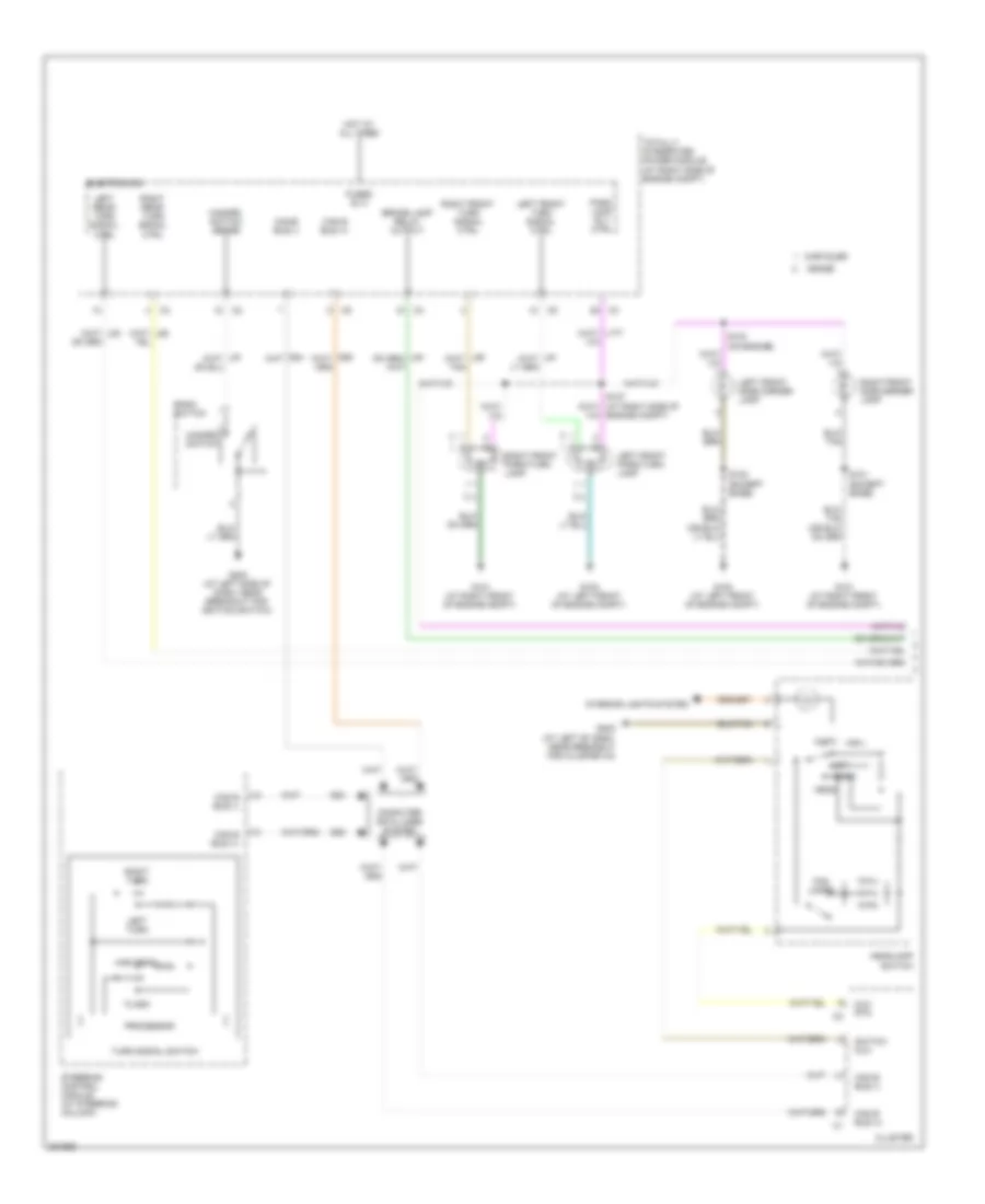
Exterior Lamps Wiring Diagram (1 of 2) for Dodge Charger R/T 2008
 https://portal-diagnostov.com/license.html
Automotive Electricians Portal FZCO
Automotive Electricians Portal FZCO
https://portal-diagnostov.com/license.html
https://portal-diagnostov.com/license.html
Automotive Electricians Portal FZCO
Automotive Electricians Portal FZCOList of elements for Exterior Lamps Wiring Diagram (1 of 2) for Dodge Charger R/T 2008:
- (on engine)
- Auto
- Bank switch
- Brake lamp relay output
- Can b bus (+)
- Can b bus (-)
- Chrysler
- Cluster
- Computer data lines system
- D54
- D55
- Dodge
- Electronics
- Flash
- Fog lamps
- Fused b (+)
- G100 (at left front of engine compt)
- G101 (at right front of engine compt)
- G200 (at left side of dash, near breakout for ignition switch)
- G202 (at left of dash, near breakout for cluster c3)
- Hazard switch
- Hazard switch sense
- Head
- Headlamp switch
- High beam
- Hot at all times
- Interior lights system
- Left front park/turn lamp
- Left front side marker lamp
- Left front turn signal ctrl
- Left rear turn signal ctrl
- Left turn
- Mux rtn
- Off
- Park
- Park lamp rly ctrl
- Processor
- Right front park/turn lamp
- Right front side marker lamp
- Right front turn signal ctrl
- Right rear turn signal ctrl
- Right turn
- S101 (except base)
- S102 (except base)
- S103
- S127
- Steering control module (at steering column)
- Switch mux
- Totally integrated power module (at right side of engine compt)
- Turn signal switch
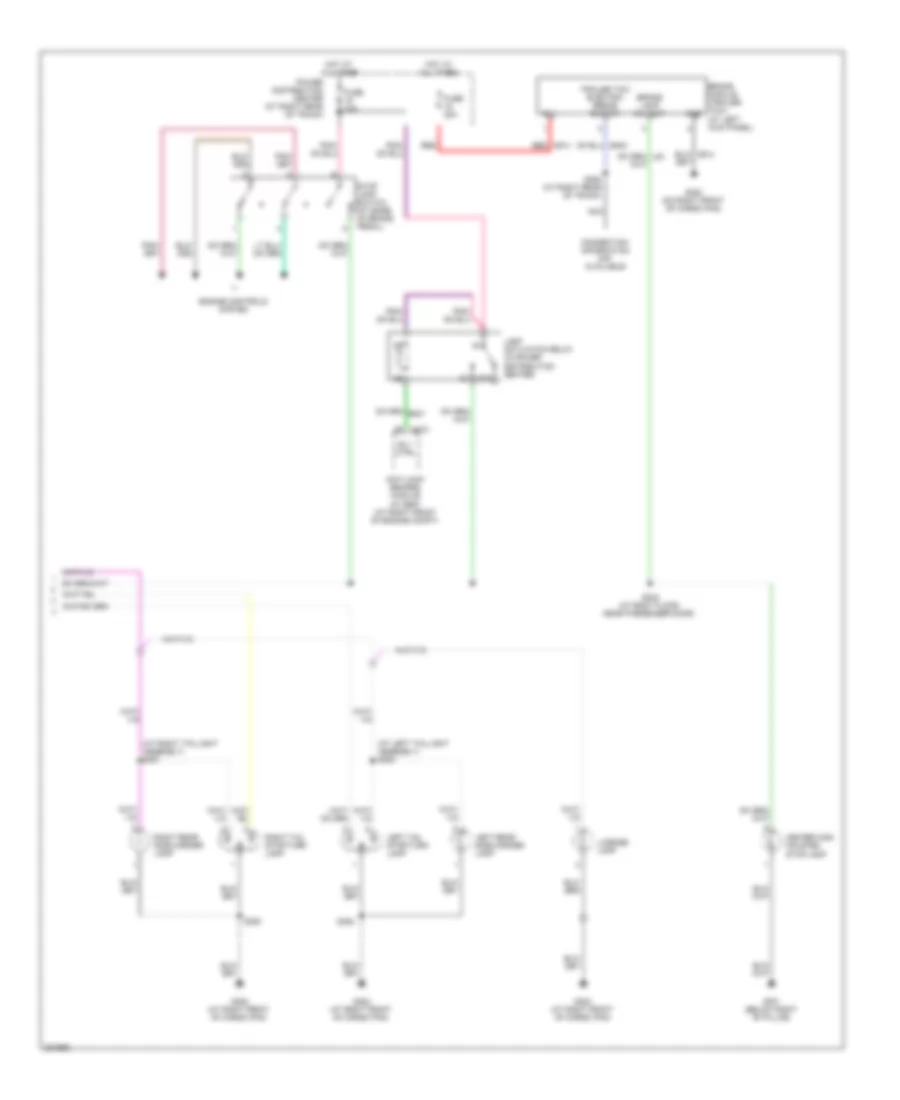
Exterior Lamps Wiring Diagram (2 of 2) for Dodge Charger R/T 2008
 https://portal-diagnostov.com/license.html
Automotive Electricians Portal FZCO
Automotive Electricians Portal FZCO
https://portal-diagnostov.com/license.html
https://portal-diagnostov.com/license.html
Automotive Electricians Portal FZCO
Automotive Electricians Portal FZCOList of elements for Exterior Lamps Wiring Diagram (2 of 2) for Dodge Charger R/T 2008:
- (acc)
- (at left taillight assembly) s353
- (at right taillight assembly) s351
- 87a
- Anti-lock brakes module (w/ esp) (at right front of engine compt)
- B(+)
- Brake lamp rly out
- Brake module (trailer tow) (at left kick panel)
- Center high mounted stop lamp
- Connection information not available
- Engine controls system
- Fuse 10a
- Fuse 20a
- G301 (below right "b" pillar)
- G302 (at right front of cargo pan)
- G302 (on right front of cargo pan)
- Gnd
- Hot at all times
- Lamp activation relay (in power distribution center)
- Left rear side marker lamp
- Left tail stop/turn lamp
- License lamp
- Nca
- Power distribution center (at right rear of trunk)
- Red
- Red a914
- Right rear side marker lamp
- Right tail stop/turn lamp
- Rly ctrl
- S302 (at body floor, near passenger door)
- S350
- S352
- S362 (at right rear of trunk)
- Stop lamp switch (at base of brake pedal)
- Trailer tow electric brake output
GROUND DISTRIBUTION
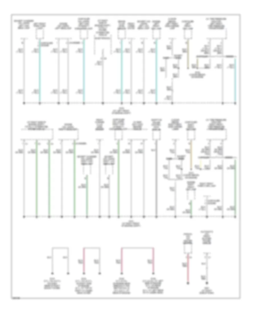
Ground Distribution Wiring Diagram (1 of 4) for Dodge Charger R/T 2008
 https://portal-diagnostov.com/license.html
Automotive Electricians Portal FZCO
Automotive Electricians Portal FZCO
https://portal-diagnostov.com/license.html
https://portal-diagnostov.com/license.html
Automotive Electricians Portal FZCO
Automotive Electricians Portal FZCOList of elements for Ground Distribution Wiring Diagram (1 of 4) for Dodge Charger R/T 2008:
- (4 door sedan) left front side marker lamp
- (4 door sedan) right front side marker lamp
- (at right side of engine compt) totally integrated power module
- (at right side of engine compt) totally power integrated module
- (automatic a/c) front blower power module
- (charger)
- (chrysler hid lamps) left high intensity discharge lamp
- (chrysler hid lamps) right high intensity discharge lamp
- (chrysler) (dodge)
- (chrysler) left front fog lamp
- (chrysler) right front fog lamp
- (dodge hid lamps) left headlamp
- (dodge hid lamps) right headlamp
- (dodge) left front fog lamp
- (dodge) right front fog lamp
- (except charger hid lamps) left high beam lamp
- (except charger hid lamps) right high beam lamp
- (except hid lamps) left low beam lamp
- (except hid lamps) right low beam lamp
- (manual a/c) a/c heater control
- (w/ esp) anti-lock brakes module
- (w/ tire pressure monitor) left front tire pressure transponder
- (w/ tire pressure monitor) right front tire pressure transponder
- Adaptive cruise control (acc) module
- Base
- Brake fluid level sensor
- Chrysler
- Dodge
- Electronics
- Except base
- Front washer fluid level sensor
- Front wiper motor
- G100 (at left front of engine compt)
- G101 (at right front of engine compt)
- G103 (2.7l, 3.5l & 5.7l) (on dash, rear of right shock tower)
- G104 (2.7l, 3.5l & 5.7l: on right side of engine) (6.1l: at top of right cylinder head cover)
- G105 (2.7l & 3.5l: on engine near breakout for ignition coil 5) (5.7l & 6.1l: at rear of engine)
- G106 (2.7l & 3.5l: at left side of engine) (5.7l: on rear of engine) (6.1l: at left rear of cylinder head)
- G201 (at right side of dash)
- Left front park/turn lamp
- Right front park/turn lamp
- S101 (4 door sedan) (on engine)
- S102 (4 door sedan) (on engine)
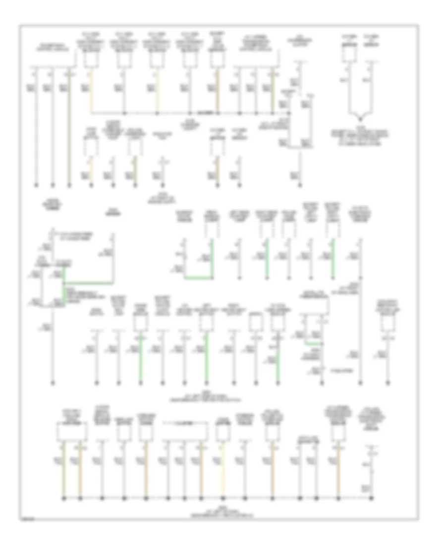
Ground Distribution Wiring Diagram (2 of 4) for Dodge Charger R/T 2008
 https://portal-diagnostov.com/license.html
Automotive Electricians Portal FZCO
Automotive Electricians Portal FZCO
https://portal-diagnostov.com/license.html
https://portal-diagnostov.com/license.html
Automotive Electricians Portal FZCO
Automotive Electricians Portal FZCOList of elements for Ground Distribution Wiring Diagram (2 of 4) for Dodge Charger R/T 2008:
- (4 door sedan) decklid release switch
- (4 door sedan) windshield washer pump
- (5.7l mds) multi displacement system cyl 1 solenoid
- (5.7l mds) multi displacement system cyl 4 solenoid
- (5.7l mds) multi displacement system cyl 6 solenoid
- (5.7l mds) multi displacement system cyl 7 solenoid
- (column w/ 5 speed transmission) electronic shift module
- (except 6.1l) egr valve assembly
- (except police) analog clock module
- (except police) glove box lamp
- (except police) left vanity lamp
- (except police) right vanity lamp
- (midline ii/ highline) radio amplifier
- (police) dome lamp
- (police) police/taxi interface module
- (police) underhood lamp
- (w/ 4 speed transmission) powertrain control module
- (w/ 5 speed transmission) transmission control module
- (w/ dvd) video screen module
- (w/ evic) electronic overhead module
- (w/o hands free) (w/ hands free)
- 6.1l
- A/c compressor clutch
- A/c heater control
- Bank switch
- Cigar lighter
- Cluster
- Data link connector
- Except 6.1l
- Front reading lamp
- G102 (at right of engine compt)
- G109 (except 6.1l: on right shock tower, near purge solenoid) (6.1l: at top of right cylinder head cover)
- G200 (at left side of dash, near breakout for ignition switch)
- G202 (at left of dash, near breakout for cluster c3)
- Hands free module
- Headlamp switch
- Hood ajar switch
- If equipped
- Inside rearview mirror
- Left heated seat switch
- Left rear courtesy lamp
- Occupant restraint controller module
- Oxygen 1/1 sensor
- Oxygen 1/2 sensor
- Oxygen 2/1 sensor
- Oxygen 2/2 sensor
- Powertrain control module
- Radiator fan
- Radio
- Rain sensor
- Right heated seat switch
- Right rear courtesy lamp
- S115 (5.7l: at right side of engine)
- S136 (in engine compt)
- S342 (at front of headliner)
- S343 (near breakout for inside rearview mirror)
- S394 (in audio harness)
- Satellite video module
- Steering control module
- Sunroof motor/ module
- W/ auto wipers
- W/o auto wipers
- Wireless ignition node
Ground Distribution Wiring Diagram (3 of 4) for Dodge Charger R/T 2008
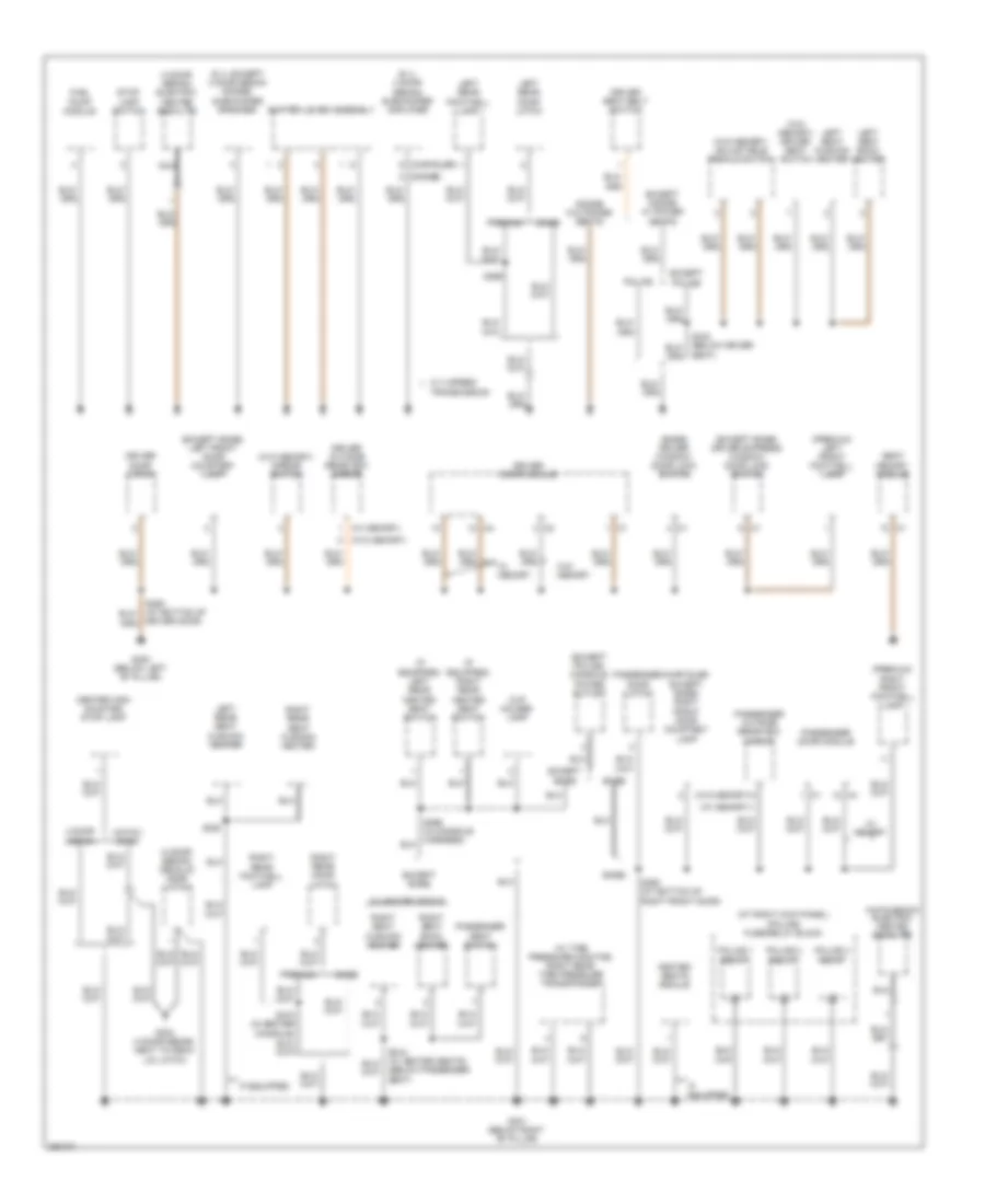 https://portal-diagnostov.com/license.html
Automotive Electricians Portal FZCO
Automotive Electricians Portal FZCO
https://portal-diagnostov.com/license.html
https://portal-diagnostov.com/license.html
Automotive Electricians Portal FZCO
Automotive Electricians Portal FZCOList of elements for Ground Distribution Wiring Diagram (3 of 4) for Dodge Charger R/T 2008:
- (4 door sedan) decklid door latch
- (4 door sedan) electric heated backlite
- (6.1l 4 door sedan) subwoofer amplifier
- (6.1l except 4 door sedan dodge) subwoofer speaker
- (at right kick panel) (police) fuse/relay block
- (base) driver window/ door lock switch
- (below passenger seat)
- (chrysler except base) right front door courtesy lamp
- (chrysler)
- (dodge)
- (except base) driver express window/ door lock switch
- (except base) left front door courtesy lamp
- (except police) console power outlet
- (hatchback) electric heated backlite
- (if equipped) left rear heated seat switch
- (if equipped) right rear heated seat switch
- (premium) left front footwell lamp
- (premium) right front footwell lamp
- (w/ memory)
- (w/ tire pressure monitor) right rear tire pressure transponder
- (w/o memory)
- (w/o memory) adjustable pedals switch
- (w/o memory) driver seat switch
- (w/o memory) mirror switch
- 4 door sedan
- Base
- Center high mounted stop lamp
- Cup holder lamp
- Dodge w/o power seats
- Driver door latch
- Driver door module
- Driver door)
- Driver outside rearview mirror
- Driver seat belt switch
- Except base
- Except dodge w/ power seats
- Except police
- Fuel pump module
- G300 (below left "b" pillar)
- G301 (below right "b" pillar)
- G304 (4 door sedan: next to deck lid latch)
- Hatch- back
- Heated seats module
- If equipped
- Left rear door latch
- Left rear footwell lamp
- Left rear seat cushion heater
- Left seat back heater
- Left seat cushion heater
- Nca
- Passenger door latch
- Passenger door module
- Passenger outside rearview mirror
- Passenger seat switch
- Police
- Police 1 relay
- Police 2 relay
- Police 3 relay
- Premium
- Right rear door latch
- Right rear footwell lamp
- Right rear seat cushion heater
- Right seat back heater
- Right seat cushion heater
- S360 (at bottom of right front door)
- S369
- S370 (in center console)
- S380
- Seat memory module
- Seat)
- Shifter lever assembly
- Stop lamp switch
- Transmission
- W/ 4 speed
- W/ heated seats
- W/ memory
- W/o memory
Ground Distribution Wiring Diagram (4 of 4) for Dodge Charger R/T 2008
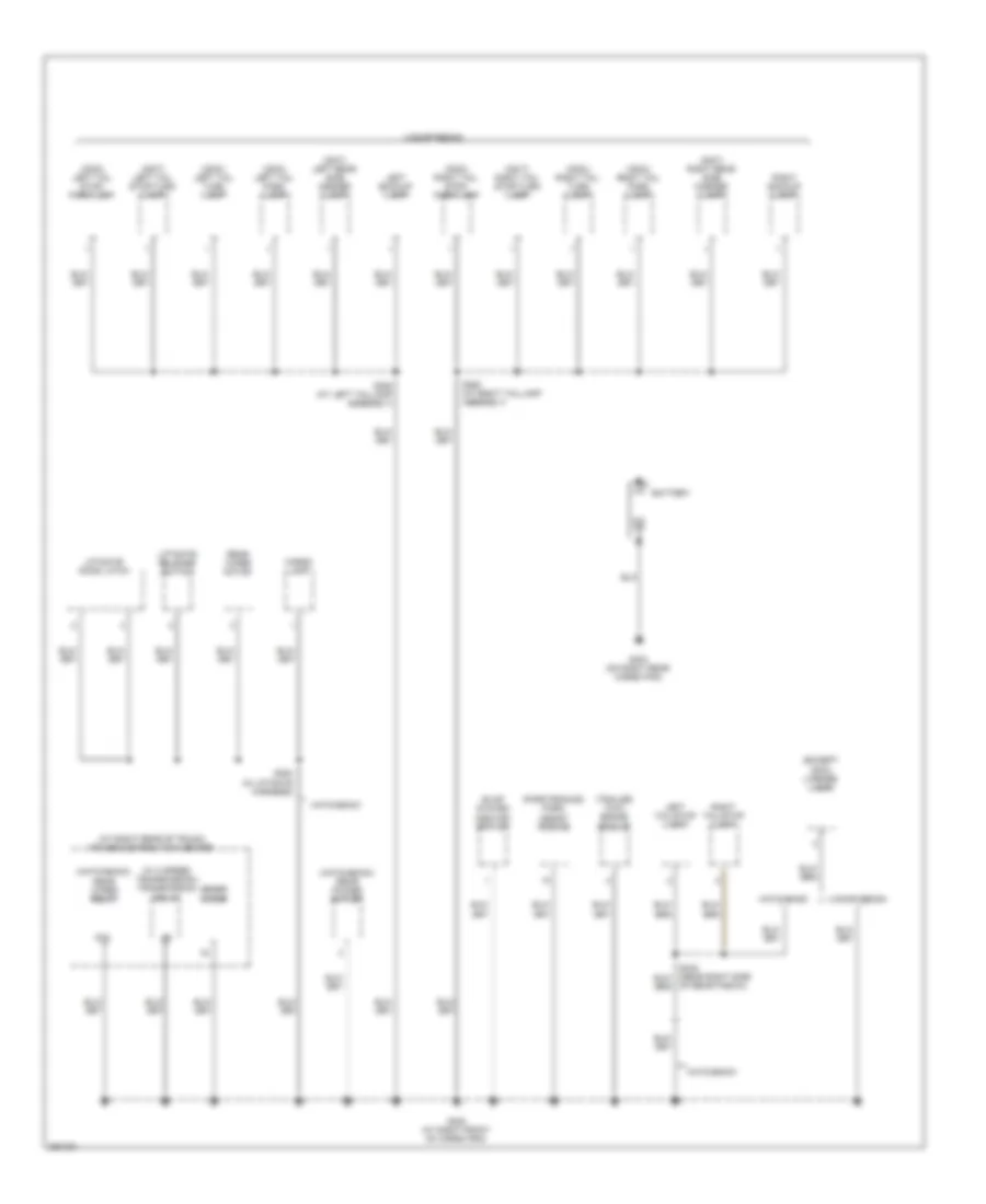 https://portal-diagnostov.com/license.html
Automotive Electricians Portal FZCO
Automotive Electricians Portal FZCO
https://portal-diagnostov.com/license.html
https://portal-diagnostov.com/license.html
Automotive Electricians Portal FZCO
Automotive Electricians Portal FZCOList of elements for Ground Distribution Wiring Diagram (4 of 4) for Dodge Charger R/T 2008:
- (300c) left tail park lamp
- (300c) left tail stop/ park lamp
- (300c) left tail turn lamp
- (300c) right tail park lamp
- (300c) right tail stop/ park lamp
- (300c) right tail turn lamp
- (300t) left rear side marker lamp
- (300t) left tail stop/turn lamp
- (300t) right rear side marker lamp
- (300t) right tail stop/turn lamp
- (at right rear of trunk) power distribution center
- (except 300c) license lamp
- (hatchback) rear power outlet
- (hatchback) rear wiper relay
- (parktronics) park assist module
- (trailer tow) brake module
- (w/ 5 speed transmission) transmission relay
- 4 door sedan
- 87a
- Battery
- Cargo lamp
- Evap system monitor switch
- G302 (at right front of cargo pan)
- G303 (on right rear cargo pan)
- Hatchback
- Left backup lamp
- Left tail/stop lamp
- Liftgate door latch
- Liftgate release switch
- Of rear fascia)
- Rear wiper motor
- Right backup lamp
- Right tail/stop lamp
- S350 (at right taillamp assembly)
- S352 (at left taillamp assembly)
- S354 (in liftgate harness)
- Zener diode
HEADLIGHTS
Headlights Wiring Diagram for Dodge Charger R/T 2008
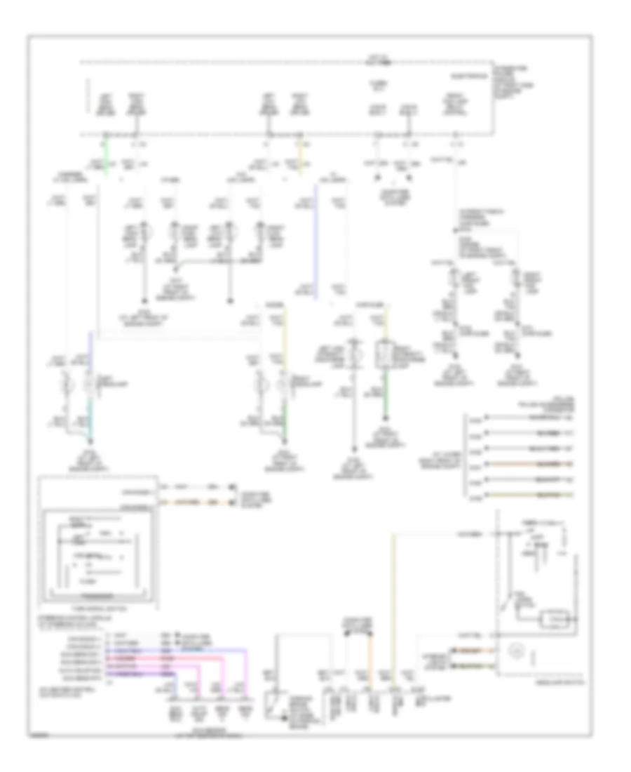 https://portal-diagnostov.com/license.html
Automotive Electricians Portal FZCO
Automotive Electricians Portal FZCO
https://portal-diagnostov.com/license.html
https://portal-diagnostov.com/license.html
Automotive Electricians Portal FZCO
Automotive Electricians Portal FZCOList of elements for Headlights Wiring Diagram for Dodge Charger R/T 2008:
- (at lower right front of engine compt)
- (in front fascia harness) (chrysler) s104
- (police) police accessories connector
- A/c heater control (automatic a/c)
- Auto
- Auto hdlmp sig
- Bus (+) can b
- Bus (-) can b
- Can b bus (+)
- Can b bus (-)
- Charger w/ hid lamps
- Chrysler
- Computer data lines system
- D54
- D55
- Dodge
- Electronics
- Flash
- Fog lamps switch
- Front fog lamp relay control
- Fused b (+)
- G100 (at left front of engine compt)
- G101 (at right front of engine compt)
- G139
- G39
- G939
- Head
- Headlamp switch
- High beam
- Hot at all times
- Integrated power module (at right side of engine compt)
- Interior lights system
- L24
- Left front fog lamp
- Left headlamp
- Left high beam driver
- Left high beam lamp
- Left high intensity discharge lamp
- Left low beam driver
- Left low beam lamp
- Left turn
- Mux rtn cluster
- Mux switch
- Off
- Other
- Park
- Park brk sw sns
- Parking brake switch (at base of parking brake)
- Processor
- Right front fog lamp
- Right headlamp
- Right high beam driver
- Right high beam lamp
- Right intensity discharge lamp
- Right low beam driver
- Right low beam lamp
- Right turn
- S101 (chrysler)
- S102 (chrysler)
- S120 (dodge) (at right front of engine compt)
- S159
- S160
- S161
- S162
- S163
- S164
- Sens sig
- Steering control module (at steering column)
- Sun sens rtn
- Sun sens sig 1
- Sun sens sig 2
- Sun sensor (at top center of dash)
- Turn signal switch
- W/ hid lamps
- W/o hid lamps
HORN
Horn Wiring Diagram, Base for Dodge Charger R/T 2008
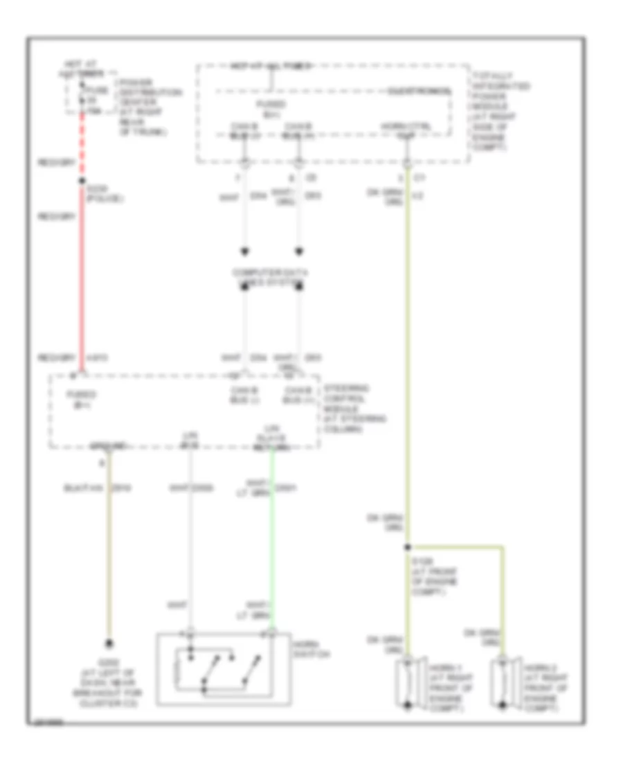 https://portal-diagnostov.com/license.html
Automotive Electricians Portal FZCO
Automotive Electricians Portal FZCO
https://portal-diagnostov.com/license.html
https://portal-diagnostov.com/license.html
Automotive Electricians Portal FZCO
Automotive Electricians Portal FZCOList of elements for Horn Wiring Diagram, Base for Dodge Charger R/T 2008:
- Can b bus (+)
- Can b bus (-)
- Computer data lines system
- D500
- D54
- D55
- Electronics
- Fuse 10a
- Fused (b+)
- Fused b(+)
- G202 (at left of dash, near breakout for cluster c3)
- Ground
- Horn 1 (at right front of engine compt)
- Horn 2 (at right front of engine compt)
- Horn ctrl out
- Horn switch
- Hot at all times
- Lin bus
- Lin slave return
- Power distribution center (at right rear of trunk)
- S128 (at front of engine compt)
- S230 (police)
- Steering control module (at steering column)
- Totally integrated power module (at right side of engine compt)
- Z910
Horn Wiring Diagram, Premium for Dodge Charger R/T 2008
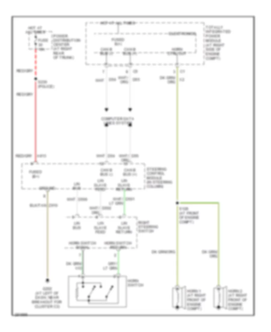 https://portal-diagnostov.com/license.html
Automotive Electricians Portal FZCO
Automotive Electricians Portal FZCO
https://portal-diagnostov.com/license.html
https://portal-diagnostov.com/license.html
Automotive Electricians Portal FZCO
Automotive Electricians Portal FZCOList of elements for Horn Wiring Diagram, Premium for Dodge Charger R/T 2008:
- A913
- Can b bus (+)
- Can b bus (-)
- Computer data lines system
- D54
- D55
- Electronics
- Fuse 10a
- Fused (b+)
- Fused b(+)
- G202 (at left of dash, near breakout for cluster c3)
- Ground
- Horn 1 (at right front of engine compt)
- Horn 2 (at right front of engine compt)
- Horn ctrl out
- Horn switch
- Horn switch return
- Horn switch signal
- Hot at all times
- Lin bus
- Lin slave feed
- Lin slave return
- Power distribution center (at right rear of trunk)
- Right steering switch
- S128 (at front of engine compt)
- S230 (police)
- Steering control module (in steering column)
- Totally integrated power module (at right side of engine compt)
INSTRUMENT CLUSTER
Instrument Cluster Wiring Diagram (1 of 2) for Dodge Charger R/T 2008
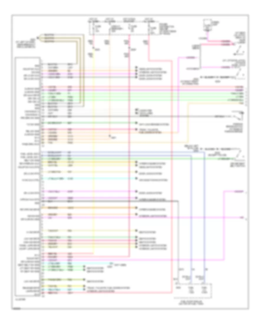 https://portal-diagnostov.com/license.html
Automotive Electricians Portal FZCO
Automotive Electricians Portal FZCO
https://portal-diagnostov.com/license.html
https://portal-diagnostov.com/license.html
Automotive Electricians Portal FZCO
Automotive Electricians Portal FZCOList of elements for Instrument Cluster Wiring Diagram (1 of 2) for Dodge Charger R/T 2008:
- (at deck lid latch) deck lid door latch
- (at liftgate latch) liftgate door latch
- (below left "b" pillar) g300
- (not used)
- 4 door sedan
- A110
- A23
- A917
- Air conditioning system
- Ajar sw sns
- Anti-lock brakes system
- B (+)
- B25
- B27
- Belt sw sns
- C105
- C200
- Can b bus (+)
- Can b bus (-)
- Cargo lamp
- Circuit breaker 1 25a
- Cluster
- Computer data lines system
- Court lmps drvr
- D54
- D55
- Dim sig
- Door locks system
- Dr ajar sw sns
- Dr lk sw mux
- Dr lk sw rtn
- Dr unlk drvr
- Driver seat belt switch
- Drv dr lk
- E12
- E22
- F202
- Fuel level sig 1
- Fuel level sig 2
- Fuel lvl 1 sig
- Fuel lvl 2 sig
- Fuel pump module (on top of fuel tank)
- Fuse 10a
- Fuse 20a
- Fuse 5a
- G160
- G161
- G167
- G202 (at left of dash, near breakout for cluster c3)
- G25
- G302 (at right front of cargo pan)
- G74
- G75
- G76
- G77
- G78
- G926
- Gnd
- Hatchback
- Hdlmp sw mux
- Hdlmp sw mux rtn
- Headlights system
- Hi ind drvr
- High ind drvr
- Hot at all times
- Hot in run or start
- Hvac mux ctrl
- Ind dim sig
- Interior lights system
- L307
- L900
- Lamps drvr
- Lft seat sw sns
- Low ind drvr
- M24
- M27
- P303
- P31
- P365
- P366
- P37
- P392
- P393
- P81
- P82
- P83
- P84
- Panel lmps drvr
- Parking brake switch (at base of parking brake)
- Pass drs unlk
- Power distribution center (at right rear of trunk)
- Prk brk sw sns
- R57
- R58
- Red/ tan
- Red/tan
- Rel sw sns
- Release drvr
- Rr wiper sw mux
- Rr wpr ind drvr
- Rt seat sw sns
- Run-start
- S200
- S201
- S209
- S333 (except police)
- S354
- Seat belt sw sns
- Seats system
- T/c sw sns
- Tan
- Trunk, tailgate, fuel doors system
- W113
- W213
- Wiper/washer system
- Wpr sw mux rtn
- Z210
- Z910
Instrument Cluster Wiring Diagram (2 of 2) for Dodge Charger R/T 2008
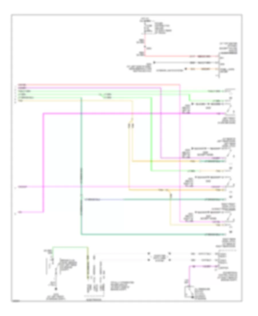 https://portal-diagnostov.com/license.html
Automotive Electricians Portal FZCO
Automotive Electricians Portal FZCO
https://portal-diagnostov.com/license.html
https://portal-diagnostov.com/license.html
Automotive Electricians Portal FZCO
Automotive Electricians Portal FZCOList of elements for Instrument Cluster Wiring Diagram (2 of 2) for Dodge Charger R/T 2008:
- (at rear of left rear door) left rear door latch
- (at top center of dash) (except police) analog clock module
- (except base)
- A117
- B(+)
- B20
- Brake fluid level sensor (at left rear of engine compt)
- Bus (+) can c
- Can c bus (+)
- Can c bus (-)
- Can c bus(-)
- Computer data lines system
- D64
- D65
- E12
- Electronics
- Eop sig
- Fuse 10a
- G100 (at left front of engine compt)
- G200 (at left side of dash, near breakout for ignition switch)
- G300 (below left "b" pillar)
- G301 (below right "b" pillar)
- Gnd
- Hot at all times
- Interior lights system
- Left front door latch (in driver door)
- Oil pressure switch (2.7l/3.5l) (on front of engine)
- Panel lamps driver
- Power distribution center (at right rear of trunk)
- Powertrain control module (at right rear of engine compt)
- Right front door latch (in right front door)
- Right rear door latch (at rear of right rear door)
- S202
- S355
- S360
- S369
- S387 (except base)
- Sens switch
- Tan
- Totally integrated power module (at right side of engine compt)
- Z909
Overhead Console Wiring Diagram for Dodge Charger R/T 2008
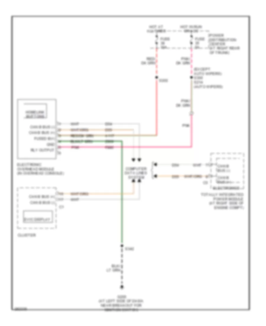 https://portal-diagnostov.com/license.html
Automotive Electricians Portal FZCO
Automotive Electricians Portal FZCO
https://portal-diagnostov.com/license.html
https://portal-diagnostov.com/license.html
Automotive Electricians Portal FZCO
Automotive Electricians Portal FZCOList of elements for Overhead Console Wiring Diagram for Dodge Charger R/T 2008:
- (except auto wipers) s300 s214 (auto wipers)
- A117
- Can b bus (+)
- Can b bus (-)
- Cluster
- Computer data lines system
- D54
- D55
- Electronic overhead module (in overhead console)
- Electronics
- Evic display
- F880
- Fuse 10a
- Fuse 5a
- Fused b(+)
- G200 (at left side of dash, near breakout for ignition switch)
- Gnd
- Homelink buttons
- Hot at all times
- Hot in run or acc
- Pnk
- Power distribution center (at right rear of trunk)
- Rly output
- S202
- S342
- Totally integrated power module (at right side of engine compt)
- Z909
Police/Taxi Interface Module Wiring Diagram for Dodge Charger R/T 2008
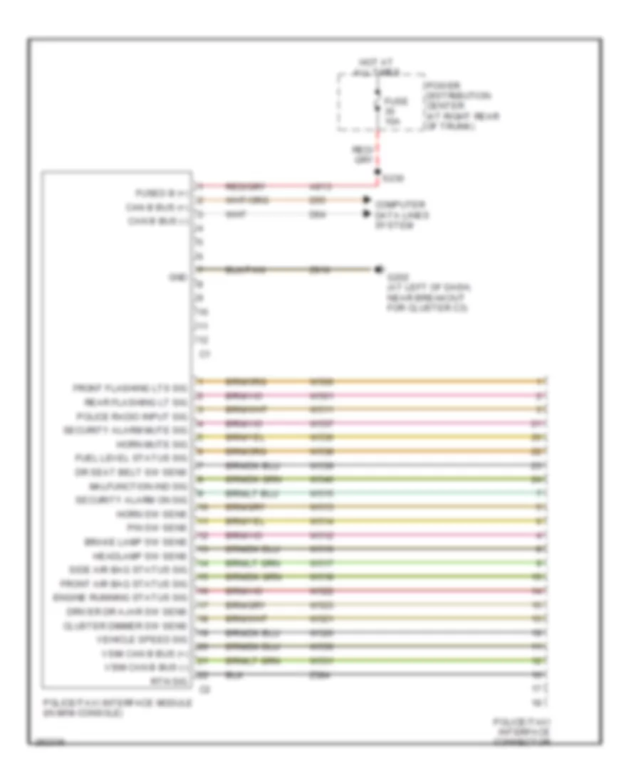 https://portal-diagnostov.com/license.html
Automotive Electricians Portal FZCO
Automotive Electricians Portal FZCO
https://portal-diagnostov.com/license.html
https://portal-diagnostov.com/license.html
Automotive Electricians Portal FZCO
Automotive Electricians Portal FZCOList of elements for Police/Taxi Interface Module Wiring Diagram for Dodge Charger R/T 2008:
- A913
- Brake lamp sw sens
- Can b bus (+)
- Can b bus (-)
- Cluster dimmer sw sens
- Computer data lines system
- D54
- D55
- Dr seat belt sw sens
- Driver dr ajar sw sens
- Engine running status sig
- Front air bag status sig
- Front flashing lts sig
- Fuel level status sig
- Fuse 10a
- Fused b (+)
- G202 (at left of dash, near breakout for cluster c3)
- Gnd
- Headlamp sw sens
- Horn mute sig
- Horn sw sens
- Hot at all times
- Malfunction ind sig
- P/n sw sens
- Police radio input sig
- Police/taxi interface connector
- Police/taxi interface module (in mini-console)
- Power distribution center (at right rear of trunk)
- Rear flashing lt sig
- Rtn sig
- S230
- Security alarm mute sig
- Security alarm on sig
- Side air bag status sig
- Vehicle speed sig
- Vsim can b bus (+)
- Vsim can b bus (-)
- W500
- W501
- W511
- W512
- W513
- W514
- W515
- W516
- W517
- W518
- W521
- W522
- W523
- W526
- W530
- W531
- W536
- W537
- W538
- W539
- W540
- Z384
- Z910
INTERIOR LIGHTS
Courtesy Lamps Wiring Diagram (1 of 2) for Dodge Charger R/T 2008
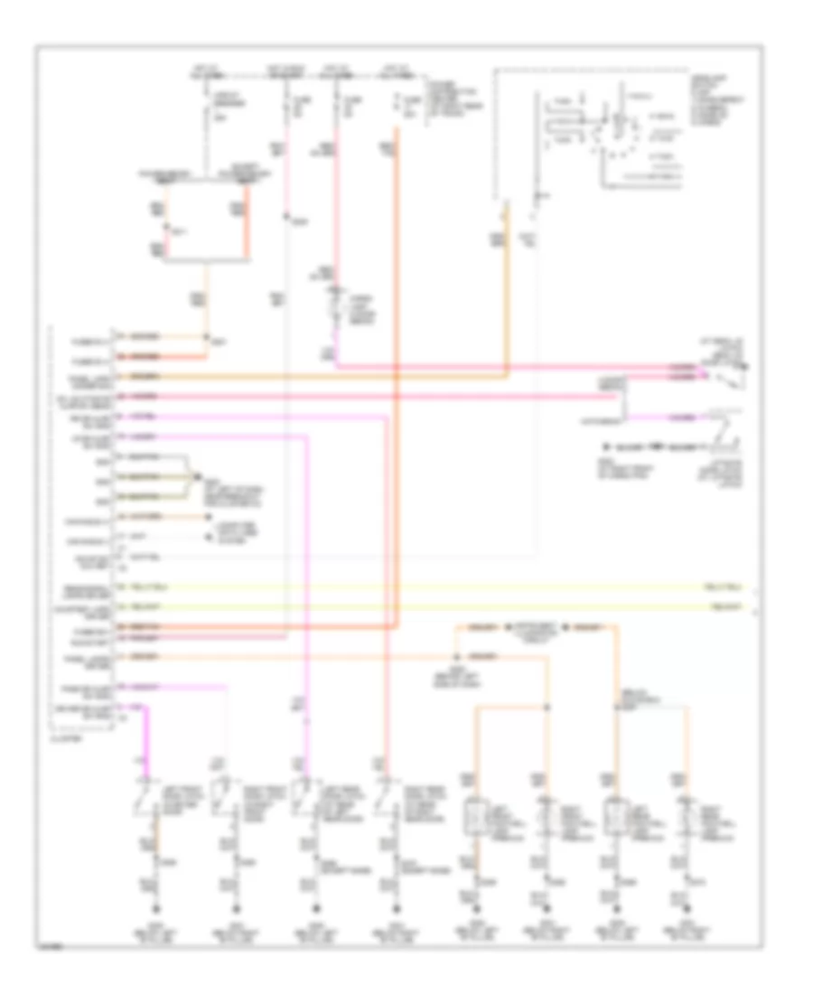 https://portal-diagnostov.com/license.html
Automotive Electricians Portal FZCO
Automotive Electricians Portal FZCO
https://portal-diagnostov.com/license.html
https://portal-diagnostov.com/license.html
Automotive Electricians Portal FZCO
Automotive Electricians Portal FZCOList of elements for Courtesy Lamps Wiring Diagram (1 of 2) for Dodge Charger R/T 2008:
- (at deck lid latch) deck lid door latch
- (below glove box) s387
- 4 door sedan
- Can b bus (+)
- Can b bus (-)
- Cargo lamp (4 door sedan)
- Circuit breaker 25a
- Cluster
- Computer data lines system
- Courtesy lmps driver
- Dk lid/lftgate ajar sw sens
- Driver dr ajar sw sns
- Except power/memory seat
- Fuse 20a
- Fuse 5a
- Fused b (+)
- Fused b(+)
- G202 (at left of dash, near breakout for cluster c3)
- G300 (below left "b" pillar)
- G301 (below right "b" pillar)
- G302 (at right front of cargo pan)
- Gnd
- Hatchback
- Hdlmp sw mux ret
- Headlamp switch 0) off 1) dome defeat 2) funeral 3) dome on 4) cargo
- Hot at all times
- Hot in run or start
- Instrument illumination circuit
- Left front door latch (in driver door)
- Left front footwell lamp (premium)
- Left rear door latch (at rear of left rear door)
- Left rear footwell lamp (premium)
- Liftgate door latch (at liftgate latch)
- Lr dr ajar sw sns
- Panel lamps driver
- Panel lmps dimmer sig
- Pass dr ajar sw sns
- Power distribution center (at right rear of trunk)
- Power/memory seat
- Reading/rail lamps driver
- Red/ tan
- Red/tan
- Right front door latch (in right front door)
- Right front footwell lamp (premium)
- Right rear door latch (at rear of right rear door)
- Right rear footwell lamp (premium)
- Rr dr ajar sw sns
- Run-start
- S201
- S208 (behind left side of dash)
- S209
- S311
- S354
- S355
- S360
- S369
- S369 (except base)
- S370
- S370 (except base)
Courtesy Lamps Wiring Diagram (2 of 2) for Dodge Charger R/T 2008
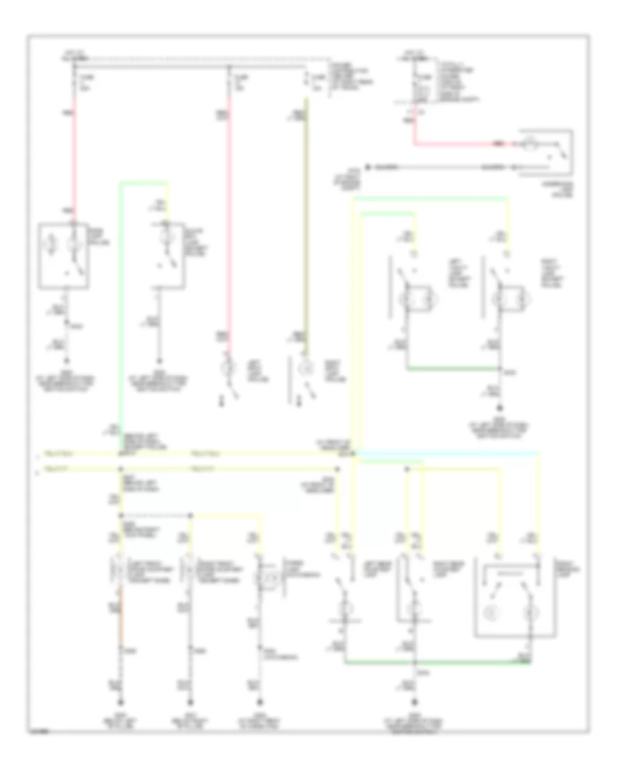 https://portal-diagnostov.com/license.html
Automotive Electricians Portal FZCO
Automotive Electricians Portal FZCO
https://portal-diagnostov.com/license.html
https://portal-diagnostov.com/license.html
Automotive Electricians Portal FZCO
Automotive Electricians Portal FZCOList of elements for Courtesy Lamps Wiring Diagram (2 of 2) for Dodge Charger R/T 2008:
- (at front of headliner) s341
- Cargo lamp (hatchback)
- Dome lamp (police)
- Front reading lamp
- Fuse (5.7l/ 6.1l) 25a
- Fuse 15a
- Fuse 20a
- G102 (at right of engine compt)
- G200 (at left side of dash, near breakout for ignition switch)
- G300 (below left "b" pillar)
- G301 (below right "b" pillar)
- G302 (at right front of cargo pan)
- Glove box lamp (except police)
- Hot at all times
- Kick panel)
- Left front door courtesy lamp (except base)
- Left rear courtesy lamp
- Left spot lamp (police)
- Left vanity lamp (except police)
- Power distribution center (at right rear of trunk)
- Red
- Right front door courtesy lamp (except base)
- Right rear courtesy lamp
- Right spot lamp (police)
- Right vanity lamp (except police)
- S227 (behind left side of dash)
- S306 (behind right
- S340 (at front of headliner)
- S342
- S354 (hatchback)
- S355
- S360
- Totally integrated power module (at right side of engine compt)
- Underhood lamp (police)
Instrument Illumination Wiring Diagram for Dodge Charger R/T 2008
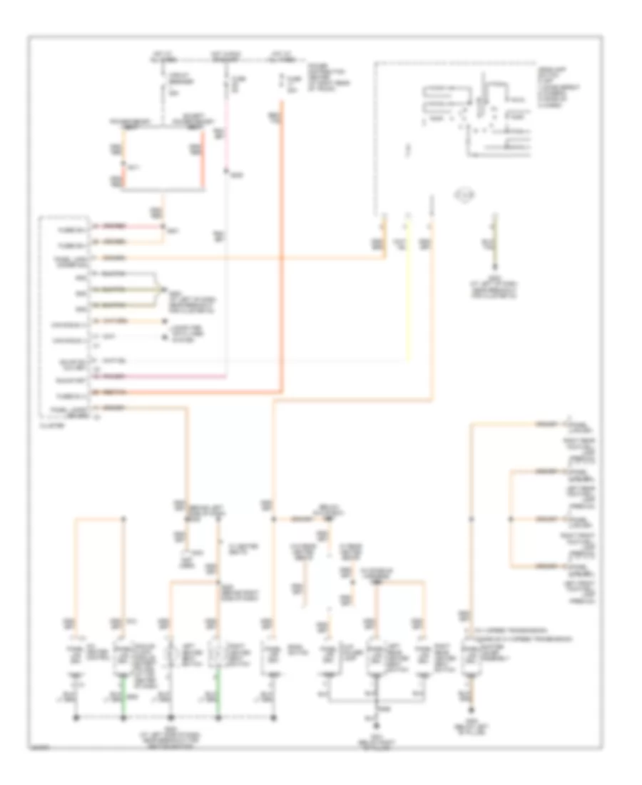 https://portal-diagnostov.com/license.html
Automotive Electricians Portal FZCO
Automotive Electricians Portal FZCO
https://portal-diagnostov.com/license.html
https://portal-diagnostov.com/license.html
Automotive Electricians Portal FZCO
Automotive Electricians Portal FZCOList of elements for Instrument Illumination Wiring Diagram for Dodge Charger R/T 2008:
- (below glove box) s387
- (console w/ 5 speed transmission)
- (in console harness) s365
- (not used)
- (w/ 4 speed transmission)
- A/c heater control
- Analog clock module (except police) (at top center of dash)
- Bank switch
- C204
- Can b bus (+)
- Can b bus (-)
- Circuit breaker 25a
- Cluster
- Computer data lines system
- Cup holder lamp
- E12
- Except power/memory seat
- Fuse 20a
- Fuse 5a
- Fused b (+)
- Fused b(+)
- G200 (at left side of dash, near breakout for ignition switch)
- G202 (at left of dash, near breakout for cluster c3)
- G300 (below left "b" pillar)
- G301 (below right "b" pillar)
- Gnd
- Hdlmp sw mux ret
- Headlamp switch 0) off 1) dome defeat 2) funeral 3) dome on 4) cargo
- Hot at all times
- Hot in run or start
- Left front footwell lamp (premium)
- Left heated seat switch
- Left rear footwell lamp (premium)
- Left rear heated seat switch
- Panel lamps driver
- Panel lmps dimmer sig
- Panel lps drv
- Power distribution center (at right rear of trunk)
- Power/memory seat
- Red/ tan
- Red/tan
- Right front footwell lamp (premium)
- Right heated seat switch
- Right rear footwell lamp (premium)
- Right rear heated seat switch
- Run-start
- S201
- S209
- S220 (behind right side of dash)
- S311
- S366
- Shifter lever assembly
- W/ heated seats
- W/ rear heated seats
- W/o rear heated seats
- Z909
MEMORY SYSTEMS
Memory Systems Wiring Diagram (1 of 2) for Dodge Charger R/T 2008
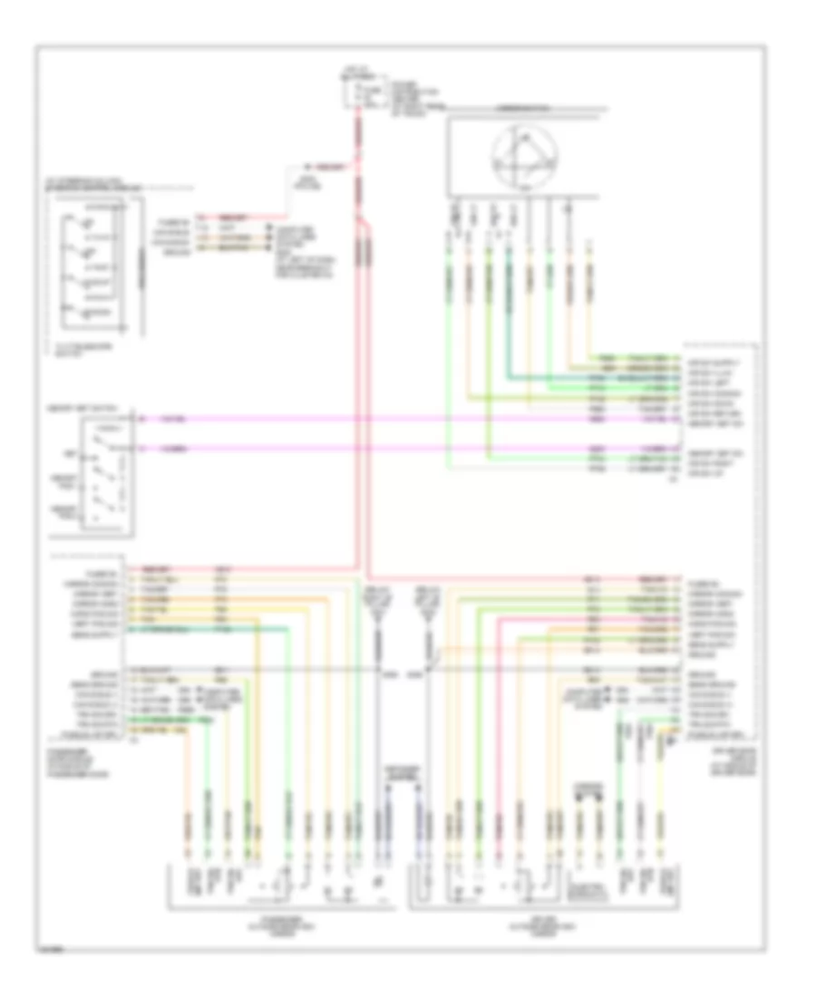 https://portal-diagnostov.com/license.html
Automotive Electricians Portal FZCO
Automotive Electricians Portal FZCO
https://portal-diagnostov.com/license.html
https://portal-diagnostov.com/license.html
Automotive Electricians Portal FZCO
Automotive Electricians Portal FZCOList of elements for Memory Systems Wiring Diagram (1 of 2) for Dodge Charger R/T 2008:
- (at steering column) steering control module
- (below left "b" pillar) g300
- (below right "b" pillar) g301
- A913
- Can b bus (+)
- Can b bus (-)
- Can b bus+
- Can b bus-
- Computer data lines system
- Computer data lines system g202 (at left of dash, near breakout for cluster c3)
- D54
- D55
- Defogger system
- Driver door module (at middle of driver door)
- Driver outside rearview mirror
- E55
- Electro- chromatic
- Fuse 10a
- Fused b+
- Fwd/up
- G200
- G920
- Ground
- Hor lt
- Hor rt
- Horiz pos sig
- Hot at all times
- M41
- M42
- Memory pos 1
- Memory pos 2
- Memory set sw
- Memory set switch
- Mir sw common
- Mir sw down
- Mir sw illum
- Mir sw left
- Mir sw return
- Mir sw right
- Mir sw up
- Mirror common
- Mirror horiz
- Mirror switch
- Mirror vert
- Mirrors system
- Off
- P145
- P146
- P501
- P502
- P550
- P591
- P592
- P64
- P65
- P66
- P67
- P68
- P69
- P70
- P703
- P704
- P705
- P706
- P71
- P710
- P72
- P73
- P74
- P75
- P950
- Passenger door module (in middle of passenger door)
- Passenger outside rearview mirror
- Power distribution center (at right rear of trunk)
- Processor
- Puddle lmp drv
- Rwd/dn
- S230 (police)
- S355
- S360
- Sens ground
- Set
- Tan
- Tilt/telescope switch
- Trn sig drv
- Trn sig rtn
- Ver lt
- Ver rt
- Vert pos sig
- Z911
- Z912
Memory Systems Wiring Diagram (2 of 2) for Dodge Charger R/T 2008
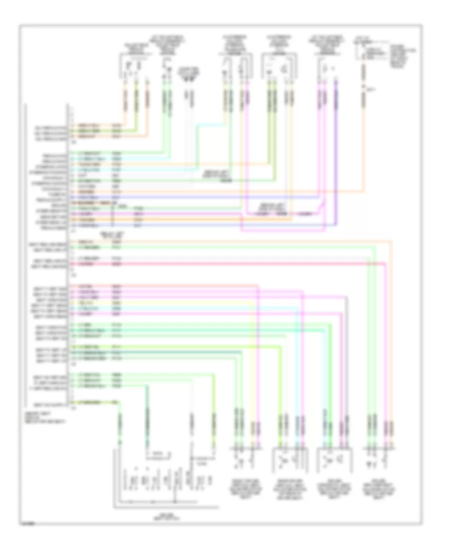 https://portal-diagnostov.com/license.html
Automotive Electricians Portal FZCO
Automotive Electricians Portal FZCO
https://portal-diagnostov.com/license.html
https://portal-diagnostov.com/license.html
Automotive Electricians Portal FZCO
Automotive Electricians Portal FZCOList of elements for Memory Systems Wiring Diagram (2 of 2) for Dodge Charger R/T 2008:
- (at adjustable pedals assembly) adjustable pedals motor
- (at adjustable pedals assembly) adjustable pedals sensor
- (behind left side of dash) s225
- (behind left side of dash) s226
- (below left "b" pillar)
- (in steering column) steering telescope motor
- (in steering column) steering tilt motor
- A110
- Adj pedals fwd
- Adj pedals gnd
- Adj pedals rwd
- Adjustable pedals switch
- Can b bus (+)
- Can b bus (-)
- Circuit breaker 1 25a
- Computer data lines system
- D54
- D55
- Driver horizontal seat adjuster motor (below driver seat)
- Driver recliner seat adjuster motor (below driver seat)
- Driver seat switch
- F dn
- F up
- F vert/recline sw
- Front driver vertical seat adjuster motor (below driver seat)
- Fused b+
- Fwd
- G13
- G14
- G300
- G401
- G402
- G403
- G404
- G491
- G492
- G493
- G494
- G914
- Ground
- Hot at all times
- Memory seat module (below driver seat)
- P111
- P113
- P115
- P117
- P119
- P121
- P141
- P143
- P151
- P152
- P153
- P157
- P205
- P206
- P239
- P339
- P599
- P953
- Pedals fwd
- Pedals rwd
- Pedals sens
- Power distribution center (at right rear of trunk)
- Q101
- Q102
- Q103
- R dn
- R up
- R vert/horiz sw
- Rear driver vertical seat adjuster motor (on rear of driver seat)
- Rec dn
- Rec up
- Rwd
- S311
- Seat f vert dn
- Seat f vert sens
- Seat f vert sns
- Seat f vert up
- Seat horiz fwd
- Seat horiz rwd
- Seat horiz sens
- Seat horiz sns
- Seat r vert dn
- Seat r vert sens
- Seat r vert sns
- Seat r vert up
- Seat recline dn
- Seat recline sens
- Seat recline sns
- Seat recline up
- Seat sw return
- Sens return
- Steer sens f/r
- Steer sens u/d
- Steering common
- Steering fwd/rwd
- Steering up/dn
- Z912
NAVIGATION
Navigation Wiring Diagram for Dodge Charger R/T 2008
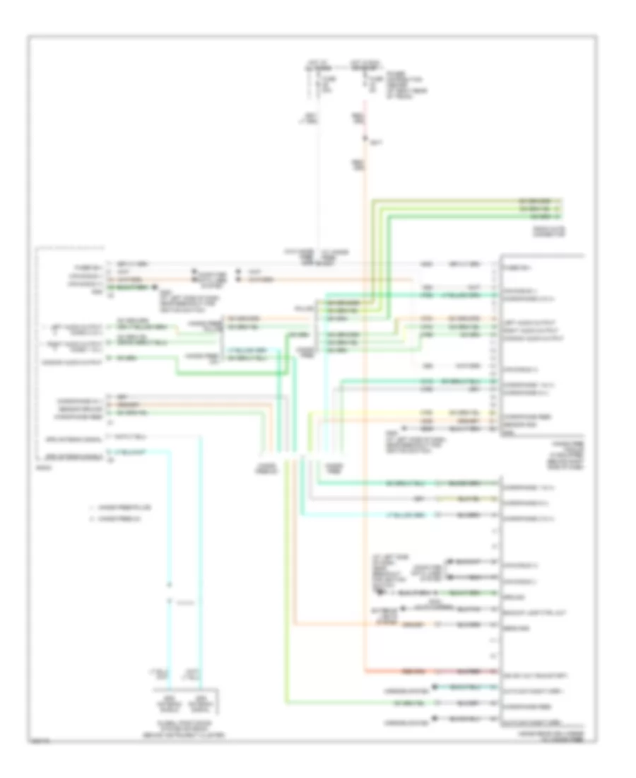 https://portal-diagnostov.com/license.html
Automotive Electricians Portal FZCO
Automotive Electricians Portal FZCO
https://portal-diagnostov.com/license.html
https://portal-diagnostov.com/license.html
Automotive Electricians Portal FZCO
Automotive Electricians Portal FZCOList of elements for Navigation Wiring Diagram for Dodge Charger R/T 2008:
- (at left side of dash, near breakout for ignition switch)
- (w/ hands free) s203
- (w/o hands free) s399
- A300
- Auto day/night mirr +
- Auto day/night mirr -
- Backup lamp ctrl out
- Can b bus (+)
- Can b bus (-)
- Common audio output
- Computer data lines system
- D54
- D55
- Exterior lights system
- Fuse 20a
- Fuse 5a
- Fused b(+)
- G200
- G200 (at left side of dash, near breakout for ignition switch)
- Global positioning system antenna (behind instrument cluster)
- Gnd
- Gps antenna shield
- Gps antenna signal
- Ground
- Hands free
- Hands free module (if equipped) (behind right side of dash)
- Hands free/ police
- Hands free/ ucii
- Hands free/police
- Hands free/uc1
- Hands free/uci
- Hot at all times
- Hot in run or start
- Ign sw out (run-start)
- Inside rearview mirror (w/ hands free)
- Left audio output
- Left audio output micro 2 in (-)
- Microphone 1 in (+)
- Microphone 2 in (+)
- Microphone feed
- Microphone in (-)
- Mirrors system
- Police
- Power distribution center (at right rear of trunk)
- Radio
- Radio mute connector
- Right audio output
- Right audio output micro 1 in (-)
- S217
- S343 (auto wipers)
- Sens gnd
- Sensor gnd
- Sensor ground
- X703
- X704
- X712
- X722
- X792
- X793
- X795
- X835
- Z909
Parking Assistant Wiring Diagram for Dodge Charger R/T 2008
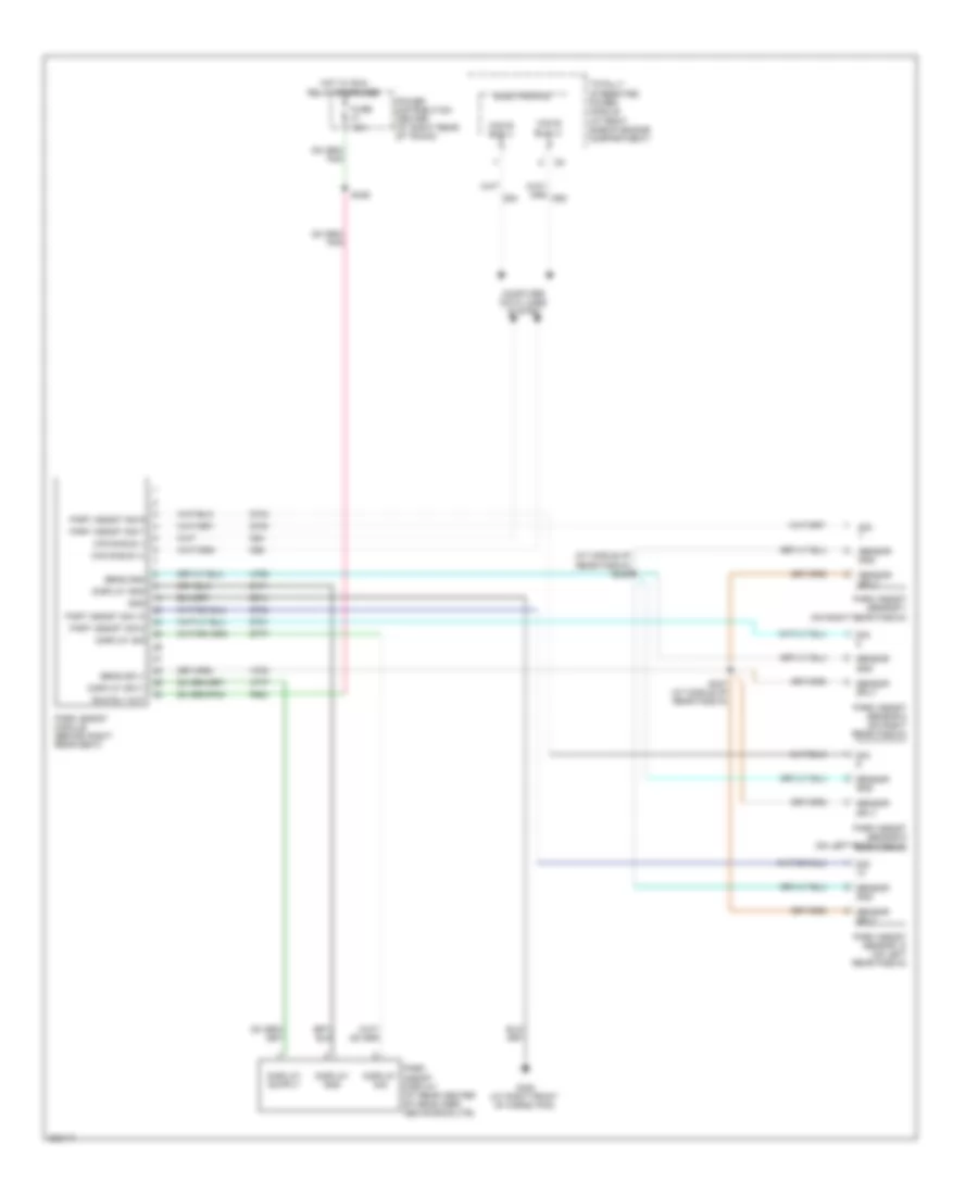 https://portal-diagnostov.com/license.html
Automotive Electricians Portal FZCO
Automotive Electricians Portal FZCO
https://portal-diagnostov.com/license.html
https://portal-diagnostov.com/license.html
Automotive Electricians Portal FZCO
Automotive Electricians Portal FZCOList of elements for Parking Assistant Wiring Diagram for Dodge Charger R/T 2008:
- (at middle of rear fascia) s346
- Can b bus (+)
- Can b bus (-)
- Computer data lines system
- D54
- D55
- D700
- D701
- D703
- D704
- D777
- Display gnd
- Display sig
- Display sply
- Electronics
- F500
- Fuse 10a
- G302 (at right front of cargo pan)
- Gnd
- Hot w/ run relay energized
- Park assist display (at rear center of headliner, above backlite)
- Park assist module (behind right rear seat)
- Park assist sensor 10 (on left rear fascia)
- Park assist sensor 7 (on right rear fascia)
- Park assist sensor 8 (on right rear fascia)
- Park assist sensor 9 (on left rear fascia)
- Part assist sig 10
- Part assist sig 7
- Part assist sig 8
- Part assist sig 9
- Power distribution center (at right rear of trunk)
- Run rly out
- S326
- S347 (at middle of rear fascia)
- Sens gnd
- Sens sply
- Sensor gnd
- Sensor sply
- Sig
- Totally integrated power module (at right side of engine compartment)
- X700
- X750
- X777
- Z171
- Z914
POWER DISTRIBUTION
Power Distribution Wiring Diagram (1 of 5) for Dodge Charger R/T 2008
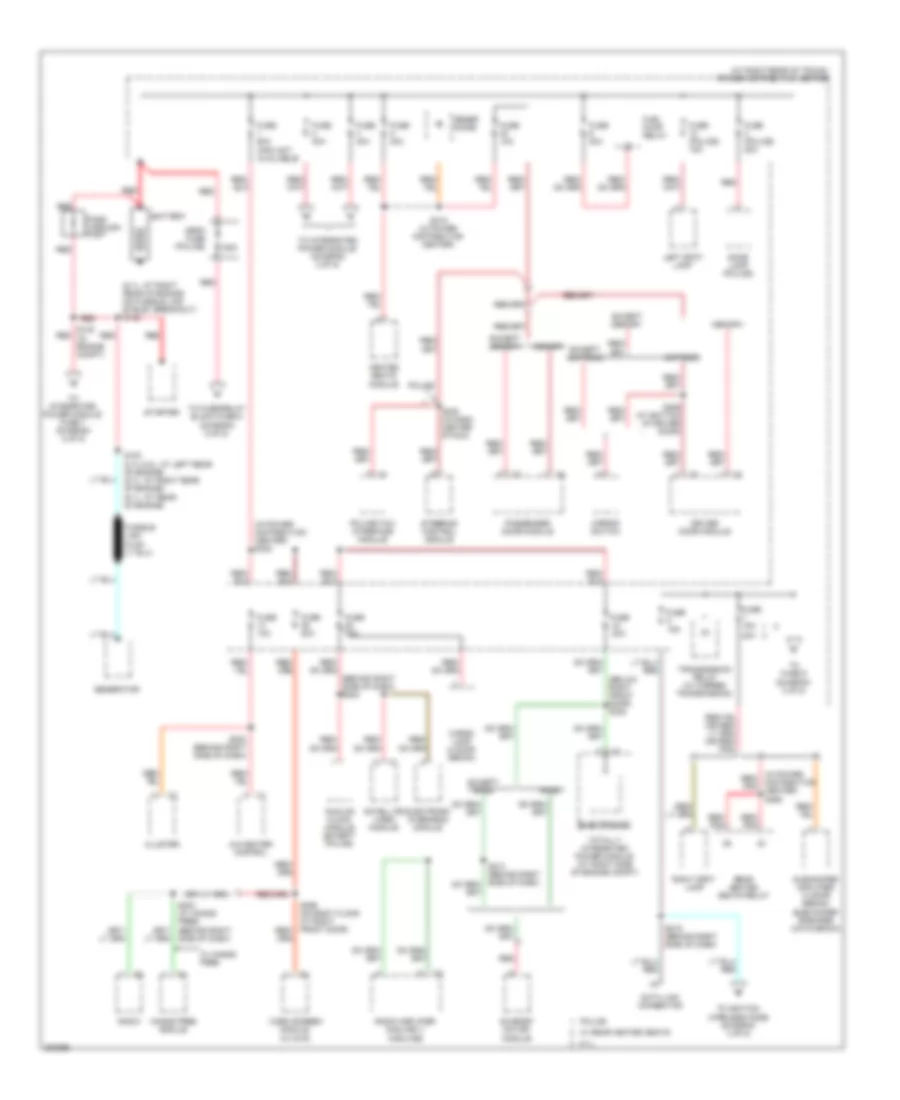 https://portal-diagnostov.com/license.html
Automotive Electricians Portal FZCO
Automotive Electricians Portal FZCO
https://portal-diagnostov.com/license.html
https://portal-diagnostov.com/license.html
Automotive Electricians Portal FZCO
Automotive Electricians Portal FZCOList of elements for Power Distribution Wiring Diagram (1 of 5) for Dodge Charger R/T 2008:
- (at right rear of trunk) power distribution center
- (behind right side of dash) s202
- (below right front door) s328
- (in power distribution center) s322
- (in power red/ distribution pnk center) s368
- 125a
- 15a
- 20a
- 6.1l
- A/c heater control
- Analog clock module (except police)
- Base
- Battery
- Cargo lamp (4 door sedan)
- Cluster
- Data link connector
- Dome lamp (police)
- Driver door module
- Electronic overhead module
- Electronics
- Except base
- Except express
- Except memory
- Express
- Fuel pump relay
- Fuse
- Fuse (police) 15a
- Fuse (police) 20a
- Fuse 10a
- Fuse 15a
- Fuse 20a
- Fuse 30a
- Fuse 40a
- Fuse 60a (info not available)
- Generator
- Hands free module
- Heated seats module
- Left spot lamp
- Mega fuse (police)
- Memory
- Mirror switch
- Pass through post
- Passenger door module
- Police
- Police/taxi interface module
- Radio
- Radio amplifier (midline ii/ highline)
- Rear heated seats relay
- Red
- Red/ pnk
- Right spot lamp
- S100 (2.7l/3.5l: at left rear of engine) (5.7l: at right rear of engine) (6.1l: at rear of engine)
- S138 red (in engine compt)
- S200 (behind right side of dash)
- S215 (behind right side of dash)
- S230 (in dash center stack)
- S315 (in power distribution center)
- S359 (at bottom of driver door)
- Satellite video module
- Side of dash)
- Starter
- Steering control module
- Subwoofer amplifier (4 door sedan) subwoofer speaker (hatchback)
- Sunroof motor/ module
- To fuse 9 (diagram 3 of 5)
- To fuse/relay block fuse 5 (diagram 5 of 5)
- To ignition wireless node (diagram 4 of 5)
- To integrated power module (diagram 2 of 5)
- To integrated power module fuse 7 (diagram 2 of 5)
- Totally integrated power module (at right side of engine compt)
- Transmission relay (w/ 5 speed transmission)
- Video screen module (w/ dvd)
- W/ hands free
- W/ rear heated seats
- Zener diode
Power Distribution Wiring Diagram (2 of 5) for Dodge Charger R/T 2008
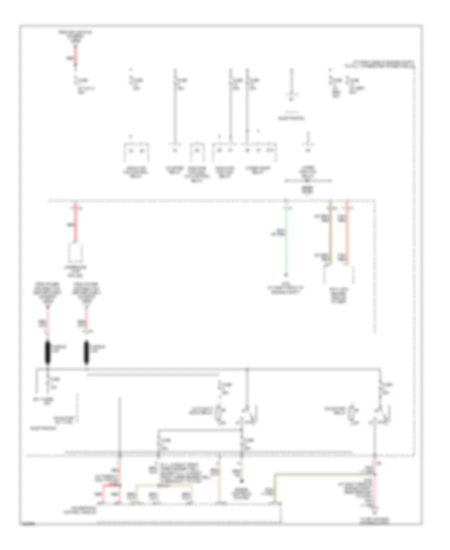 https://portal-diagnostov.com/license.html
Automotive Electricians Portal FZCO
Automotive Electricians Portal FZCO
https://portal-diagnostov.com/license.html
https://portal-diagnostov.com/license.html
Automotive Electricians Portal FZCO
Automotive Electricians Portal FZCOList of elements for Power Distribution Wiring Diagram (2 of 5) for Dodge Charger R/T 2008:
- (6.1l: in right front inner fender well) (except 6.1l: in right front inner fender well, in breakout to c100) s143
- (at right side of engine compt) totally integrated power module
- (in takeout for tipm c6) s166
- 87a
- Anti-lock brakes module (w/ esp)
- Auto shut down relay
- B(+)
- Electronics
- Engine controls system
- From power distribution center fuse 2 (diagram 1 of 5)
- From power distribution center fuse 4 (diagram 1 of 5)
- From splice s138 (diagram 1 of 5)
- Fuse (5.7l/6.1l) 25a
- Fuse (w/ esp) 30a
- Fuse (w/ esp) 50a
- Fuse 15a
- Fuse 25a
- Fuse 30a
- Fuse 40a
- Fuse 50a
- Fused b(+)
- Fusible link
- G101 (at right front of engine compt)
- Powertrain control module
- Radiator fan control relay
- Radiator fan high relay
- Radiator fan high/ low control relay
- Red
- Run/start relay
- Run/start rly ctrl
- S167 (at right rear of engine compt, near grommet to dash)
- Starter relay
- Tan/ red
- To splice s389 (diagram 4 of 5)
- Underhood lamp (police)
- Wiper high/low relay
- Wiper on/off relay
- Zener diode
Power Distribution Wiring Diagram (3 of 5) for Dodge Charger R/T 2008
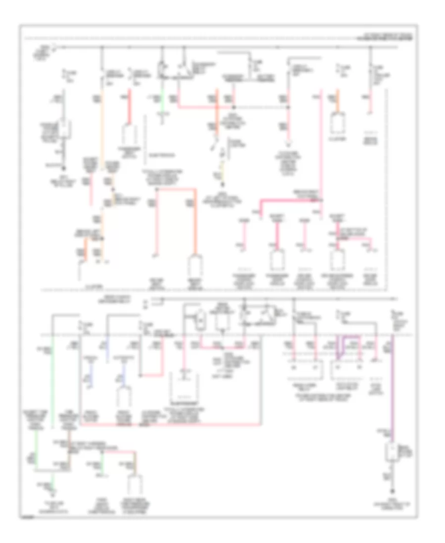 https://portal-diagnostov.com/license.html
Automotive Electricians Portal FZCO
Automotive Electricians Portal FZCO
https://portal-diagnostov.com/license.html
https://portal-diagnostov.com/license.html
Automotive Electricians Portal FZCO
Automotive Electricians Portal FZCOList of elements for Power Distribution Wiring Diagram (3 of 5) for Dodge Charger R/T 2008:
- (at bottom of driver door) s356
- (at right rear of trunk) power distribution center
- (behind left side of dash) s201
- (behind right kick panel) s317
- (diagram 1 of 5)
- (in power distribution center) s321
- (info not available)
- (not used)
- 87a
- Accessory delay relay
- Accessory position
- Activation lamp relay
- Automatic a/c
- Base
- Battery position
- Brake module
- C203
- Cigar lighter
- Circuit breaker 25a
- Circuit breaker 3 25a
- Cluster
- Console power outlet (except police)
- Diode
- Driver door module
- Driver express window/ door lock switch
- Driver seat switch
- Driver window/ door lock switch
- Electronics
- Except base
- Except power/ memory seat
- Except tire pressure monitor/ park- tronics
- From
- Front blower motor
- Front blower power module
- Fuse (hatch- back) 20a
- Fuse (trailer tow) 20a
- Fuse 10a
- Fuse 20 (hatchback) 20a
- Fuse 20a
- Fuse 30a
- Fuse 7
- G202 (at left of dash, near breakout for cluster c3)
- G301 (below right "b" pillar)
- G302 (on right front of cargo pan)
- Manual a/c
- Memory seat module
- Park assist module (parktronics)
- Passenger door module
- Passenger seat switch
- Passenger window/ door lock switch
- Pnk
- Power distribution center (at right rear of trunk)
- Power outlet
- Power/ memory seat
- Rear
- Rear heated seats relay
- Rear window defogger relay
- Rear wiper relay
- Red
- Red/ tan
- Right rear tire pressure transponder (if equipped)
- Run relay
- S323 (in power distribution center)
- Stop lamp switch
- Tire pressure monitor/ park- tronics
- To power distribution center fuse 35 (diagram 5 of 5)
- To splice s210 (diagram 5 0f 5)
- Totally integrated power module (at right side of engine compt)
Power Distribution Wiring Diagram (4 of 5) for Dodge Charger R/T 2008
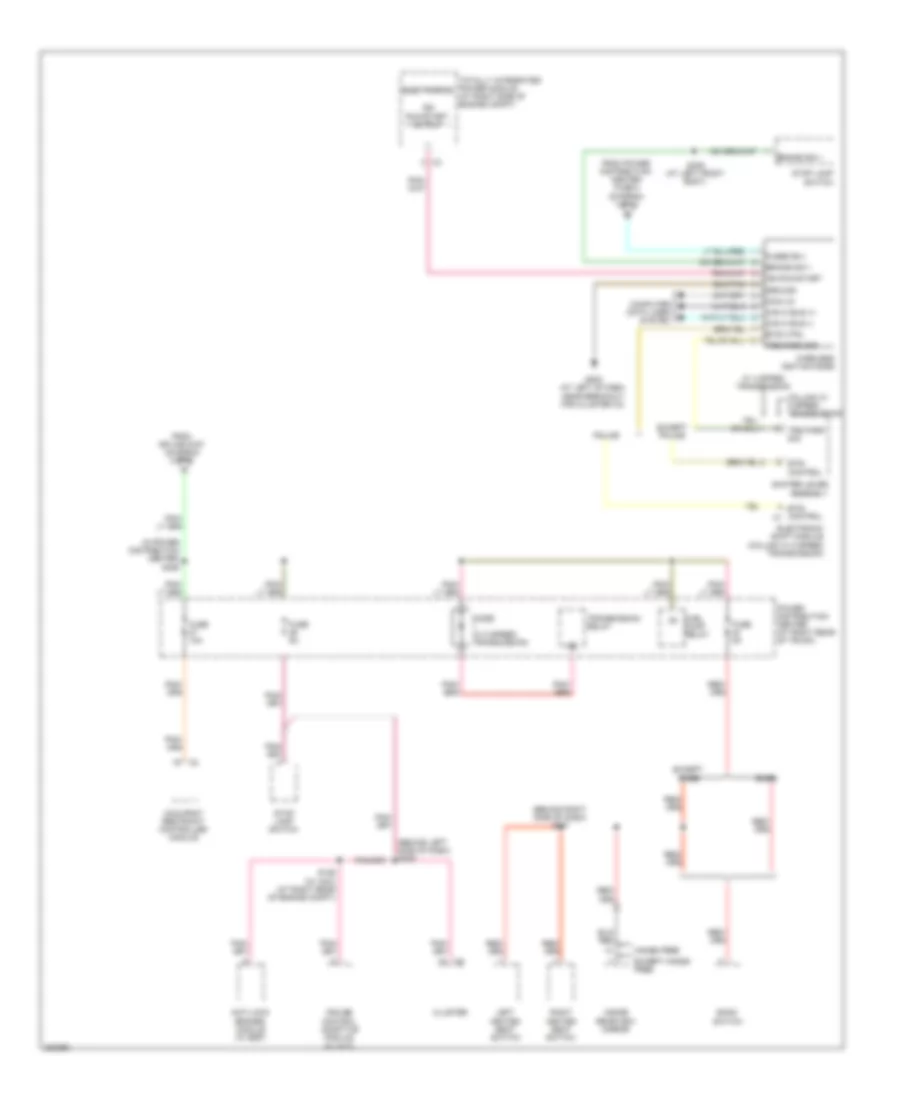 https://portal-diagnostov.com/license.html
Automotive Electricians Portal FZCO
Automotive Electricians Portal FZCO
https://portal-diagnostov.com/license.html
https://portal-diagnostov.com/license.html
Automotive Electricians Portal FZCO
Automotive Electricians Portal FZCOList of elements for Power Distribution Wiring Diagram (4 of 5) for Dodge Charger R/T 2008:
- (behind left side of dash) s209
- (behind right side of dash) s217
- (in power distribution center) s389
- Anti-lock brakes module (w/ esp)
- Bank switch
- Base
- Brake sig 1
- Btsi control
- Btsi control c1
- Btsi ctrl
- Can c bus (+)
- Can c bus (-)
- Cluster
- Column w/ 5 speed transmission
- Com-lin
- Computer data lines system
- Cruise control adaptive module (w/ acc)
- Diode (w/ 5 speed transmission)
- Electronic shift module (column w/ 5 speed transmission)
- Electronics
- Except base
- Except hands free
- Except police
- From power distribution center fuse 8 (diagram 1 of 5)
- From splice s167 (diagram 2 of 5)
- Fuel pump relay
- Fuse 10a
- Fuse 5a
- Fused b(+)
- G202 (at left of dash, near breakout for cluster c3)
- Ground
- Hands free
- Ign run-start
- Ign run-start output
- Inside rearview mirror
- Left heated seat switch
- Occupant restraint controller module
- Police
- Power distribution center (at right rear of trunk)
- Right heated seat switch
- S126 (w/ acc) (at right rear of engine compt)
- S309 (at left front body)
- Shifter lever assembly
- Stop lamp switch
- Totally integrated power module (at right side of engine compt)
- Transmission relay
- Trs park sig
- W/ 4 spped transmission
- Wireless ignition node
Power Distribution Wiring Diagram (5 of 5) for Dodge Charger R/T 2008
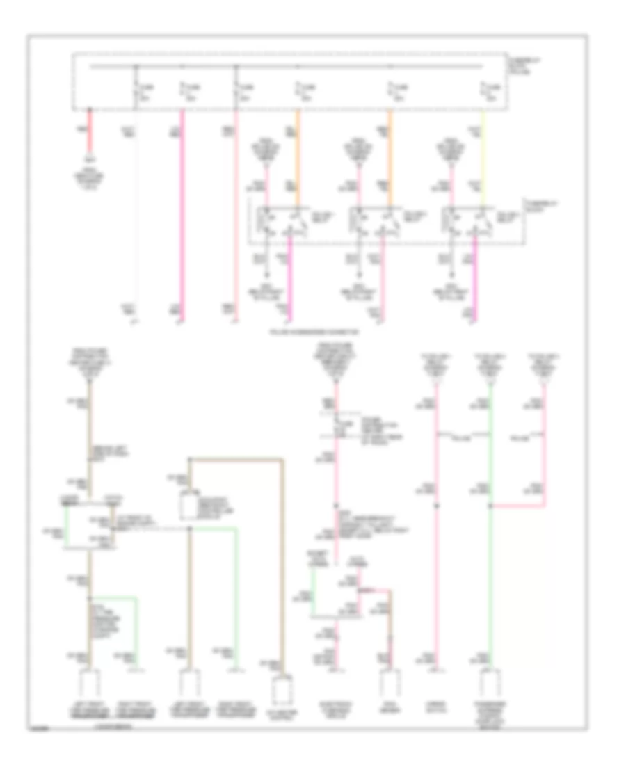 https://portal-diagnostov.com/license.html
Automotive Electricians Portal FZCO
Automotive Electricians Portal FZCO
https://portal-diagnostov.com/license.html
https://portal-diagnostov.com/license.html
Automotive Electricians Portal FZCO
Automotive Electricians Portal FZCOList of elements for Power Distribution Wiring Diagram (5 of 5) for Dodge Charger R/T 2008:
- (at front of engine compt) s131
- (behind left side of dash) s210
- 4 door sedan
- 87a
- A/c heater control
- Auto wipers
- Electronic overhead module
- Except auto wipers
- From mega fuse (diagram 1 of 5)
- From power distribution center circuit breaker 3 (diagram 3 of 5)
- From power distribution center fuse 41 (diagram 3 of 5)
- From splice 300 (diagram 5 of 5)
- Fuse 20a
- Fuse 5a
- Fuse/relay block
- Fuse/relay block (police)
- G301 (below right "b" pillar)
- Hatch- back
- Left front tire pressure transponder
- Mirror switch
- Occupant restraint controller module
- Passenger express window/ door lock switch
- Police
- Police 1 relay
- Police 2 relay
- Police 3 relay
- Police accessories connector
- Power distribution center (at right rear of trunk)
- Rain sensor
- Red
- Right front tire pressure transponder
- S140 (w/ tire pressure monitor) (in engine compt)
- S214
- To police 1 relay (diagram 5 of 5)
- To police 2 relay (diagram 5 of 5)
- To police 3 relay (diagram 5 of 5)
POWER DOOR LOCKS
Power Door Locks Wiring Diagram for Dodge Charger R/T 2008
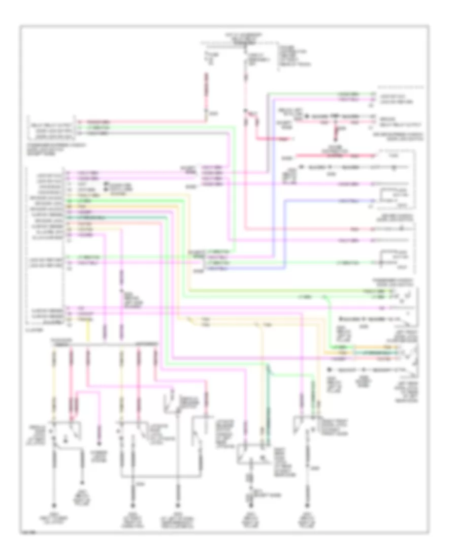 https://portal-diagnostov.com/license.html
Automotive Electricians Portal FZCO
Automotive Electricians Portal FZCO
https://portal-diagnostov.com/license.html
https://portal-diagnostov.com/license.html
Automotive Electricians Portal FZCO
Automotive Electricians Portal FZCOList of elements for Power Door Locks Wiring Diagram for Dodge Charger R/T 2008:
- (below left "b" pillar) g300
- Ajar sw sense
- Base
- Can b bus(+)
- Can b bus(-)
- Circuit breaker 3 25a
- Cluster
- Computer data lines system
- Decklid door latch (at deck lid latch)
- Decklid release switch
- Delay relay output
- Dl/lg ajar sns
- Dl/lg rel
- Dl/lg rel sw
- Door lock sw mux
- Door lock sw rtn
- Dr door lock
- Dr door unlock
- Driver express window/ door lock switch
- Driver window/ door lock switch
- Except base
- Four door
- Fuse 5a
- G202 (at left of dash, near breakout for cluster c3)
- G300 (below left "b" pillar)
- G301 (below
- G302 (at right front of cargo pan)
- G304 (next to deck lid latch)
- Ground
- Hatchback
- Hot w/ accessory delay relay energized
- Interior lights system
- Left front door latch (in driver door)
- Left rear door latch (at rear of left rear door)
- Liftgate door latch (at liftgate latch)
- Liftgate release switch (magnum: at left rear liftgate)
- Lock
- Lock sw mux
- Lock sw return
- Passenger express window/ door lock switch (except base)
- Passenger window/ door lock switch
- Pnk
- Power distribution center (at right rear of trunk)
- Power distribution system
- Right "b" pillar)
- Right front door latch (in right front door)
- Right rear door latch (at rear of right rear door)
- S228 (behind left side of dash)
- S300
- S317
- S354
- S355
- S356 pnk
- S360
- S369 (except base)
- Sedan
- Tan
- Unlk
POWER MIRRORS
Automatic Day/Night Mirror Wiring Diagram, with Hands Free for Dodge Charger R/T 2008
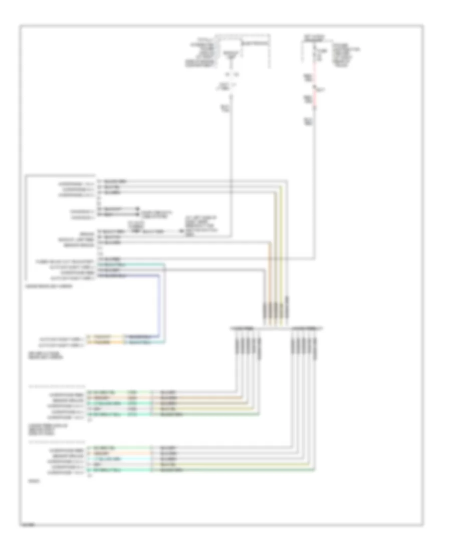 https://portal-diagnostov.com/license.html
Automotive Electricians Portal FZCO
Automotive Electricians Portal FZCO
https://portal-diagnostov.com/license.html
https://portal-diagnostov.com/license.html
Automotive Electricians Portal FZCO
Automotive Electricians Portal FZCOList of elements for Automatic Day/Night Mirror Wiring Diagram, with Hands Free for Dodge Charger R/T 2008:
- (at left side of dash, near breakout for ignition switch) g200
- (w/ auto wipers) s343
- Auto day/night mirr (+)
- Auto day/night mirr (-)
- Backup lamp
- Backup lamp feed
- Can b bus (+)
- Can b bus (-)
- Computer data lines system
- Driver outside rearview mirror
- Electronics
- Fuse 5a
- Fused ign sw out (run-start)
- Ground
- Hands free
- Hands free module (behind right side of dash)
- Hands free/uc1
- Hot in run or start
- Inside rearview mirror
- Integrated power module (at right side of engine compartment)
- Microphone 1 in (+)
- Microphone 2 in (+)
- Microphone feed
- Microphone in (-)
- Power distribution center (at right rear of trunk)
- Radio
- S217
- Sensor ground
- Totally
- X712
- X772
- X792
- X793
- X835
Automatic Day/Night Mirror Wiring Diagram, without Hands Free for Dodge Charger R/T 2008
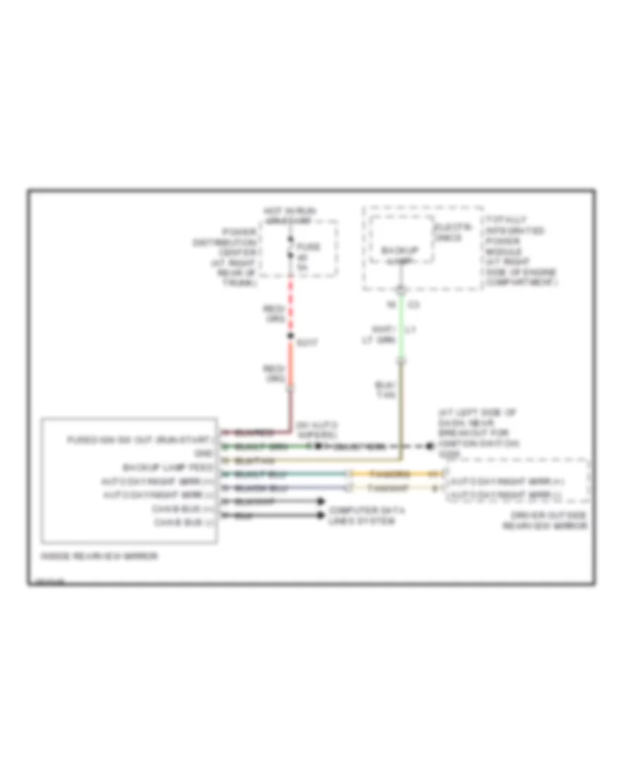 https://portal-diagnostov.com/license.html
Automotive Electricians Portal FZCO
Automotive Electricians Portal FZCO
https://portal-diagnostov.com/license.html
https://portal-diagnostov.com/license.html
Automotive Electricians Portal FZCO
Automotive Electricians Portal FZCOList of elements for Automatic Day/Night Mirror Wiring Diagram, without Hands Free for Dodge Charger R/T 2008:
- (at left side of dash, near breakout for ignition switch) g200
- (w/ auto wipers) s343
- Auto day/night mirr (+)
- Auto day/night mirr (-)
- Backup lamp
- Backup lamp feed
- Can b bus (+)
- Can b bus (-)
- Computer data lines system
- Driver outside rearview mirror
- Electr- onics
- Fuse 5a
- Fused ign sw out (run-start)
- Gnd
- Hot in run or start
- Inside rearview mirror
- Integrated power module (at right side of engine compartment)
- Power distribution center (at right rear of trunk)
- S217
- Totally
Power Mirrors Wiring Diagram for Dodge Charger R/T 2008
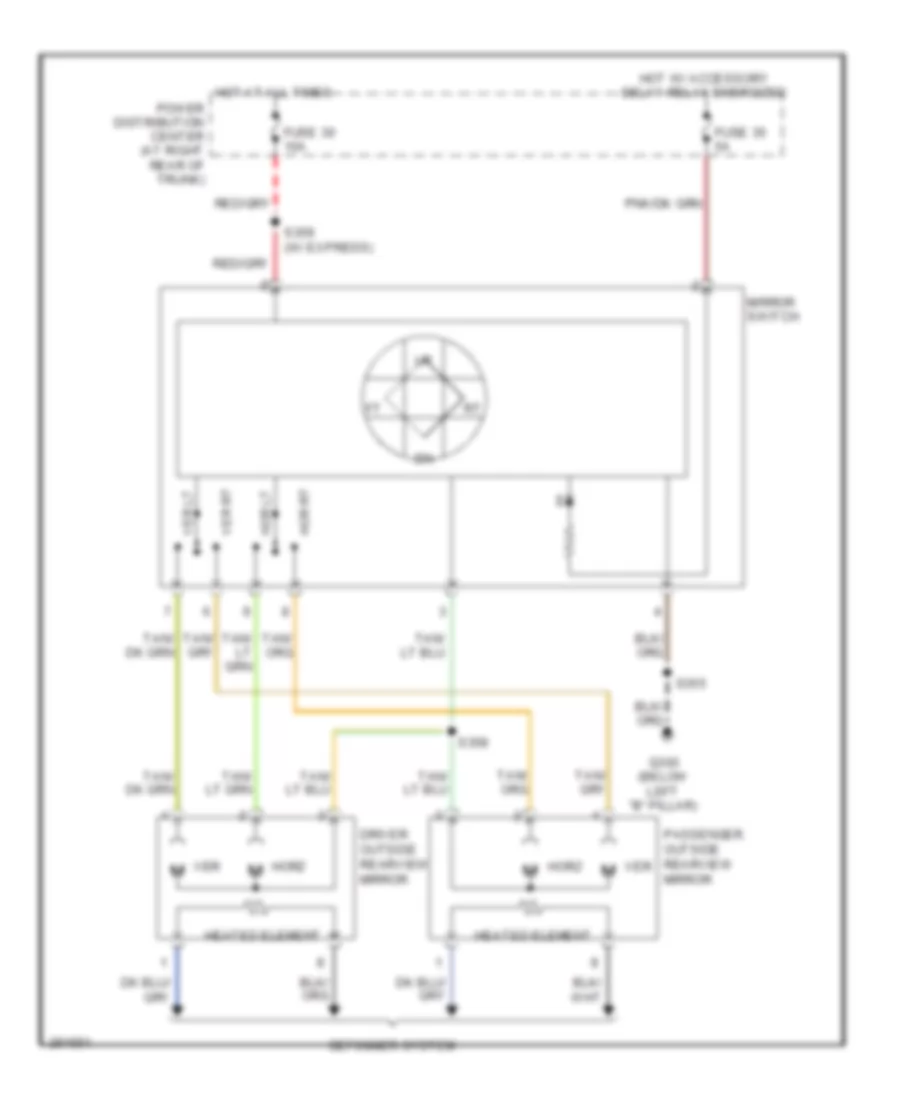 https://portal-diagnostov.com/license.html
Automotive Electricians Portal FZCO
Automotive Electricians Portal FZCO
https://portal-diagnostov.com/license.html
https://portal-diagnostov.com/license.html
Automotive Electricians Portal FZCO
Automotive Electricians Portal FZCOList of elements for Power Mirrors Wiring Diagram for Dodge Charger R/T 2008:
- Defogger system
- Driver outside rearview mirror
- Fuse 30 10a
- Fuse 35 5a
- G300 (below left "b" pillar)
- Heated element
- Hor lt
- Hor rt
- Horz
- Hot at all times
- Hot w/ accessory delay relay energized
- Mirror switch
- Passenger outside rearview mirror
- Power distribution center (at right rear of trunk)
- S355
- S358
- S359 (w/ express)
- Ver
- Ver lt
- Ver rt
POWER SEATS
Adjustable Pedal Wiring Diagram for Dodge Charger R/T 2008
 https://portal-diagnostov.com/license.html
Automotive Electricians Portal FZCO
Automotive Electricians Portal FZCO
https://portal-diagnostov.com/license.html
https://portal-diagnostov.com/license.html
Automotive Electricians Portal FZCO
Automotive Electricians Portal FZCOList of elements for Adjustable Pedal Wiring Diagram for Dodge Charger R/T 2008:
- Adj pedals relay ctrl
- Adjustable pedals motor (at adjustable pedals assembly)
- Adjustable pedals switch
- B(+)
- Electronics
- G300 (below left "b" pillar)
- Hot at all times
- Red/ a72
- S333
- Totally integrated power module (at right side of engine compartment)
Driver Power Seat Wiring Diagram for Dodge Charger R/T 2008
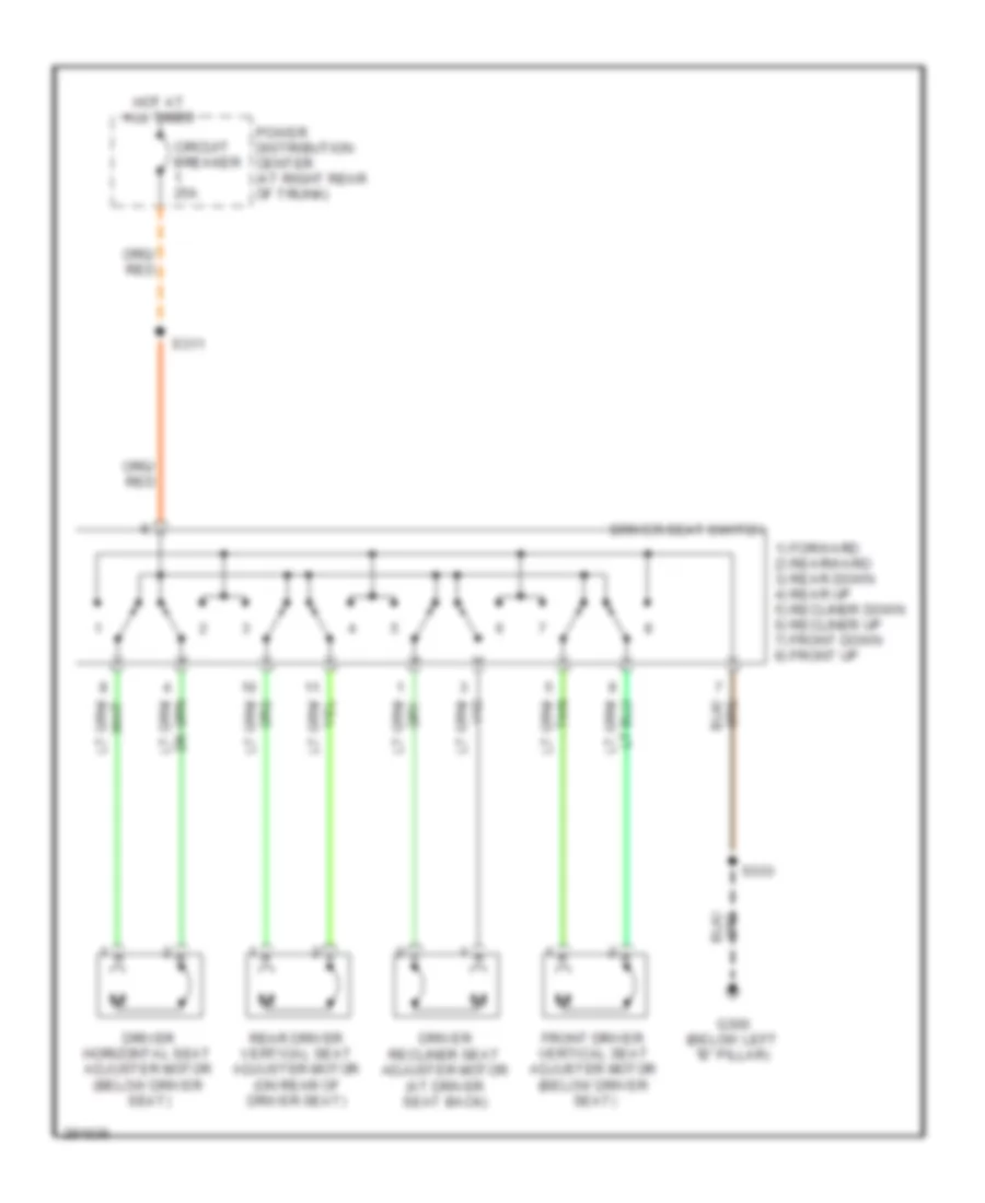 https://portal-diagnostov.com/license.html
Automotive Electricians Portal FZCO
Automotive Electricians Portal FZCO
https://portal-diagnostov.com/license.html
https://portal-diagnostov.com/license.html
Automotive Electricians Portal FZCO
Automotive Electricians Portal FZCOList of elements for Driver Power Seat Wiring Diagram for Dodge Charger R/T 2008:
- 1) forward 2) rearward 3) rear down 4) rear up 5) recliner down 6) recliner up 7) front down 8) front up
- Circuit breaker 25a
- Driver horizontal seat adjuster motor (below driver seat)
- Driver recliner seat adjuster motor (at driver seat back)
- Driver seat switch
- Front driver vertical seat adjuster motor (below driver seat)
- G300 (below left "b" pillar)
- Hot at all times
- Power distribution center (at right rear of trunk)
- Rear driver vertical seat adjuster motor (on rear of driver seat)
- S311
- S333
Front Heated Seats Wiring Diagram for Dodge Charger R/T 2008
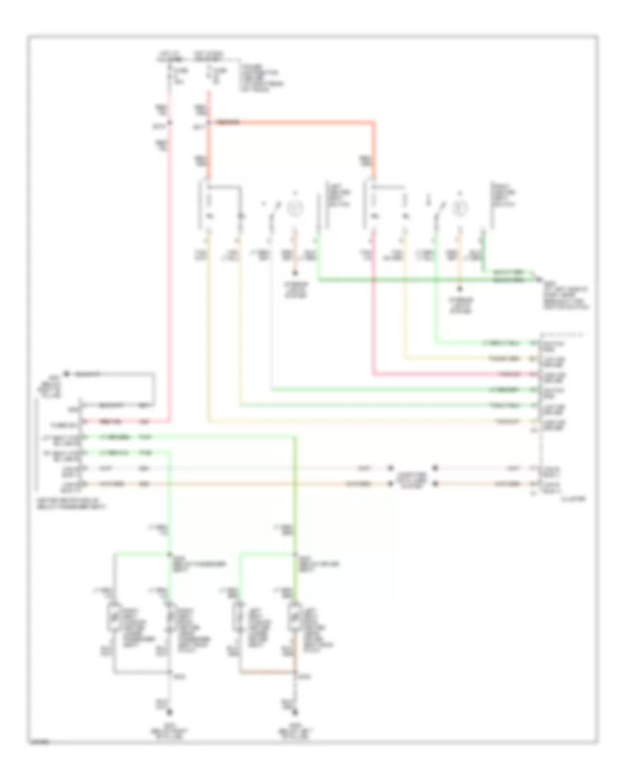 https://portal-diagnostov.com/license.html
Automotive Electricians Portal FZCO
Automotive Electricians Portal FZCO
https://portal-diagnostov.com/license.html
https://portal-diagnostov.com/license.html
Automotive Electricians Portal FZCO
Automotive Electricians Portal FZCOList of elements for Front Heated Seats Wiring Diagram for Dodge Charger R/T 2008:
- A33
- Can b bus (+)
- Can b bus (-)
- Cluster
- Computer data lines system
- D54
- D55
- Fuse 30a
- Fuse 5a
- Fused b(+)
- G200 (at left side of dash, near breakout for ignition switch)
- G300 (below left "b" pillar)
- G301 (below right "b" pillar)
- Gnd
- Heated seats module (below passenger seat)
- High ind driver
- Hot at all times
- Hot in run or start
- Interior lights system
- Left heated seat switch
- Left seat back heater (near driver seat back pivot)
- Left seat cushion heater (under driver seat)
- Lft seat htr b(+) drvr
- Low ind driver
- P187
- P188
- Power distribution center (at right rear of trunk)
- Right heated seat switch
- Right seat back heater (near passenger seat back pivot)
- Right seat cushion heater (under passenger seat)
- Rt seat htr b(+) drvr
- S217
- S315
- S332 (below driver seat)
- S333
- S334
- S335 (below passenger seat)
- Switch sns
- Z911
Passenger Power Seat Wiring Diagram for Dodge Charger R/T 2008
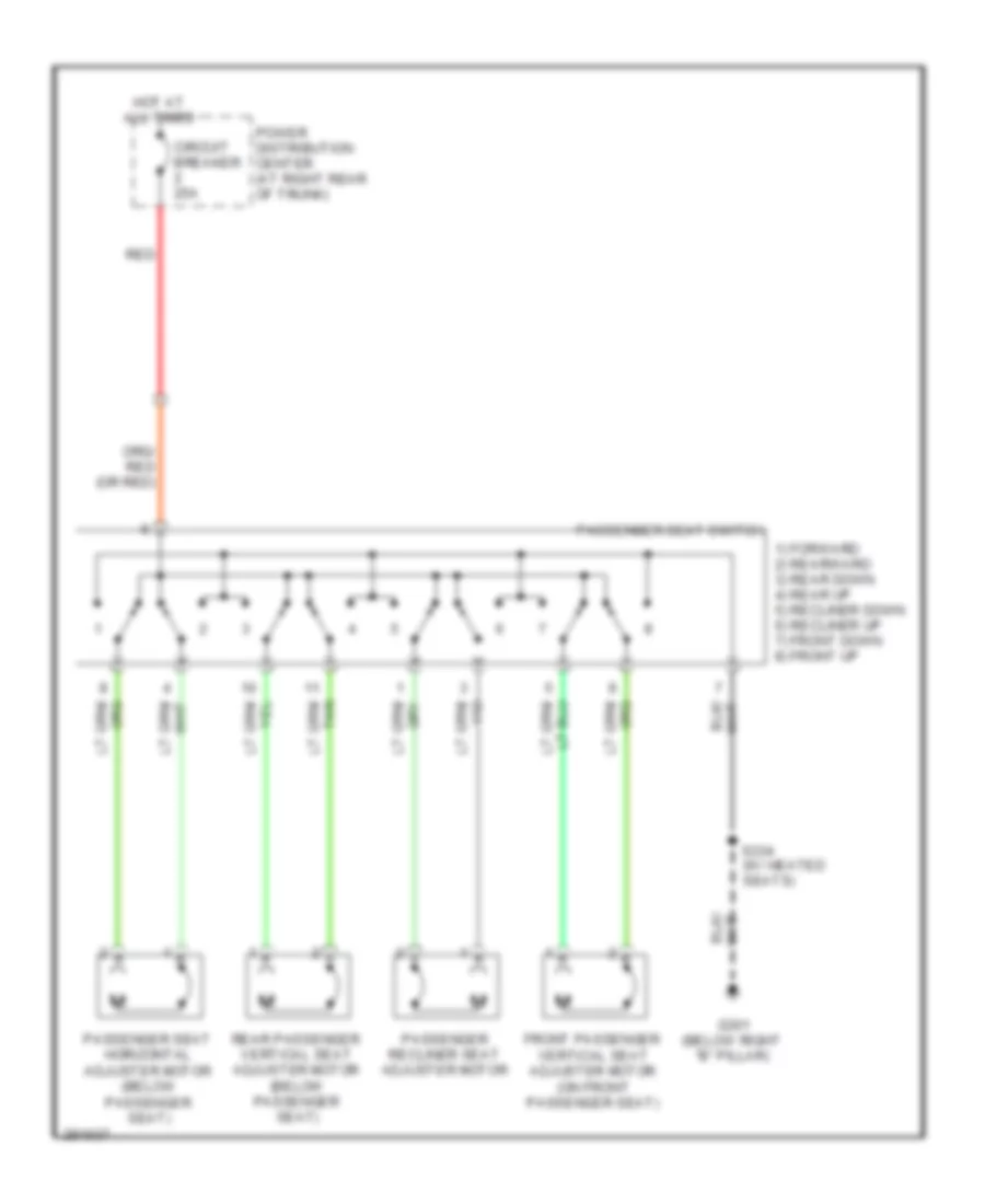 https://portal-diagnostov.com/license.html
Automotive Electricians Portal FZCO
Automotive Electricians Portal FZCO
https://portal-diagnostov.com/license.html
https://portal-diagnostov.com/license.html
Automotive Electricians Portal FZCO
Automotive Electricians Portal FZCOList of elements for Passenger Power Seat Wiring Diagram for Dodge Charger R/T 2008:
- 1) forward 2) rearward 3) rear down 4) rear up 5) recliner down 6) recliner up 7) front down 8) front up
- Circuit breaker 25a
- Front passenger vertical seat adjuster motor (on front passenger seat)
- G301 (below right "b" pillar)
- Hot at all times
- Passenger recliner seat adjuster motor
- Passenger seat horizontal adjuster motor (below passenger seat)
- Passenger seat switch
- Power distribution center (at right rear of trunk)
- Rear passenger vertical seat adjuster motor (below passenger seat)
- Red
- S334 (w/ heated seats)
Rear Heated Seats Wiring Diagram for Dodge Charger R/T 2008
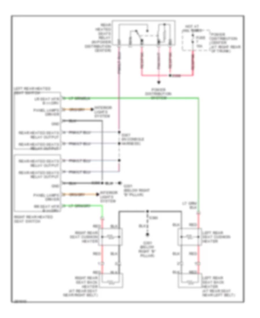 https://portal-diagnostov.com/license.html
Automotive Electricians Portal FZCO
Automotive Electricians Portal FZCO
https://portal-diagnostov.com/license.html
https://portal-diagnostov.com/license.html
Automotive Electricians Portal FZCO
Automotive Electricians Portal FZCOList of elements for Rear Heated Seats Wiring Diagram for Dodge Charger R/T 2008:
- 87a
- Fuse 15a
- G301 (below right "b" pillar)
- Gnd
- Hot at all times
- Interior lights system
- Left rear heated seat switch
- Left rear seat back heater (at rear seat near left belt)
- Left rear seat cushion heater
- Lr seat htr b (+) drv
- Panel lamps driver
- Power distribution center (at right rear of trunk)
- Power distribution system
- Rear heated seats relay (in power distribution center)
- Rear heated seats relay output
- Red
- Red/pnk
- Right rear heated seat switch
- Right rear seat back heater (at rear seat near right belt)
- Right rear seat cushion heater
- Rr seat htr b (+) drv
- S366
- S367 (in console harness)
- S368
- S380
POWER TOP/SUNROOF
Power Top/Sunroof Wiring Diagram for Dodge Charger R/T 2008
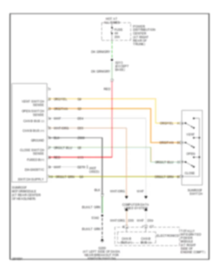 https://portal-diagnostov.com/license.html
Automotive Electricians Portal FZCO
Automotive Electricians Portal FZCO
https://portal-diagnostov.com/license.html
https://portal-diagnostov.com/license.html
Automotive Electricians Portal FZCO
Automotive Electricians Portal FZCOList of elements for Power Top/Sunroof Wiring Diagram for Dodge Charger R/T 2008:
- (not used)
- Can b bus (+)
- Can b bus (-)
- Close
- Close switch sense
- Computer data lines system
- D270
- D54
- D55
- Diagnostic
- Electronics
- Fuse 20a
- Fused b(+)
- G200 (at left side of dash, near breakout for ignition switch)
- Ground
- Hot at all times
- Open
- Open switch sense
- Power distribution center (at right rear of trunk)
- Red
- S213 (except base)
- S342
- Sunroof motor/module (at rear center of headliner)
- Sunroof switch
- Totally integrated power module (at right side of engine compt)
- Vent
- Vent switch sense
- X13
- Z909
POWER WINDOWS
Power Windows Wiring Diagram, Base for Dodge Charger R/T 2008
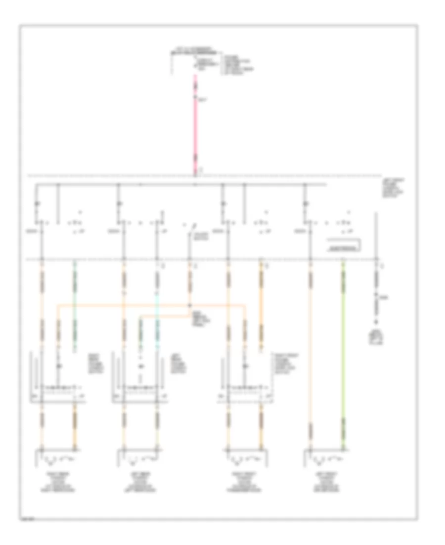 https://portal-diagnostov.com/license.html
Automotive Electricians Portal FZCO
Automotive Electricians Portal FZCO
https://portal-diagnostov.com/license.html
https://portal-diagnostov.com/license.html
Automotive Electricians Portal FZCO
Automotive Electricians Portal FZCOList of elements for Power Windows Wiring Diagram, Base for Dodge Charger R/T 2008:
- Circuit breaker 3 25a
- Down
- Electronics
- G300 (below left "b" pillar)
- Hot w/ accessory delay relay energized
- Left front power window/ door lock switch
- Left front window motor (in middle of driver door)
- Left rear power window switch
- Left rear window motor (in middle of left rear door)
- Pnk
- Power distribution center (at right rear of trunk)
- Right front power window/ door lock switch
- Right front window motor (in middle of passenger door)
- Right rear power window switch
- Right rear window motor (at middle of right rear door)
- S308 (behind left kick panel)
- S317
- S355
- Unlock switch
Power Windows Wiring Diagram, Except Base for Dodge Charger R/T 2008
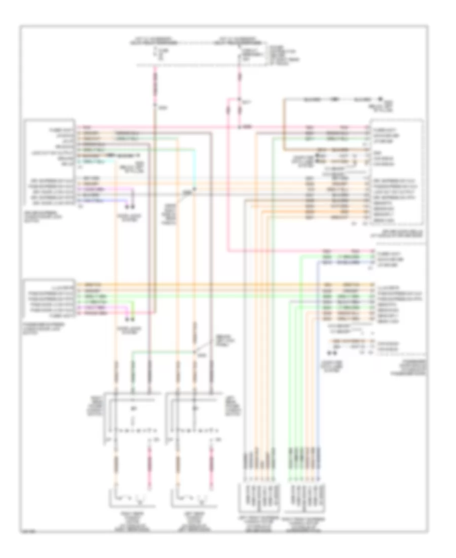 https://portal-diagnostov.com/license.html
Automotive Electricians Portal FZCO
Automotive Electricians Portal FZCO
https://portal-diagnostov.com/license.html
https://portal-diagnostov.com/license.html
Automotive Electricians Portal FZCO
Automotive Electricians Portal FZCOList of elements for Power Windows Wiring Diagram, Except Base for Dodge Charger R/T 2008:
- (behind left kick panel)
- (near right side of rear fascia)
- Can b bus+
- Can b bus-
- Circuit breaker 3 25a
- Computer data lines system
- D54
- D55
- Door locks system
- Down driver
- Driver door module (at middle of driver door)
- Driver express window/door lock switch
- Drv door lk sw mux
- Drv door lk sw rtn
- Drv express sw mux
- Drv express sw rtn
- E34
- F881
- Fuse 5a
- Fused accy
- G300 (below left "b" pillar)
- Gnd
- Ground
- Hot w/ accessory delay relay energized
- Illum drvr
- Left front express window motor (in middle of driver door)
- Left rear power window switch
- Left rear window motor (in middle of left rear door)
- Lock out sw output
- Lr down
- Lr up
- Pass door lk sw mux
- Pass door lk sw rtn
- Pass express sw mux
- Pass express sw rtn
- Passenger door module (in middle of passenger door)
- Passenger express window/door lock switch
- Pnk
- Power distribution center (at right rear of trunk)
- Q15
- Q221
- Q222
- Q301
- Q302
- Q303
- Q304
- Q305
- Q306
- Q311
- Q312
- Q321
- Q322
- Q336
- Q936
- Right front express window motor (in middle of passenger door)
- Right rear power window switch
- Right rear window motor (at middle of right rear door)
- Rr down
- Rr up
- S300
- S308
- S317
- S355
- S356
- S361
- Sens a sig
- Sens b sig
- Sens rtn
- Sens sply
- Up driver
- W/ memory
- W/o memory
- Z404
- Z405
- Z421
- Z912
RADIO
Radio Wiring Diagram, Base for Dodge Charger R/T 2008
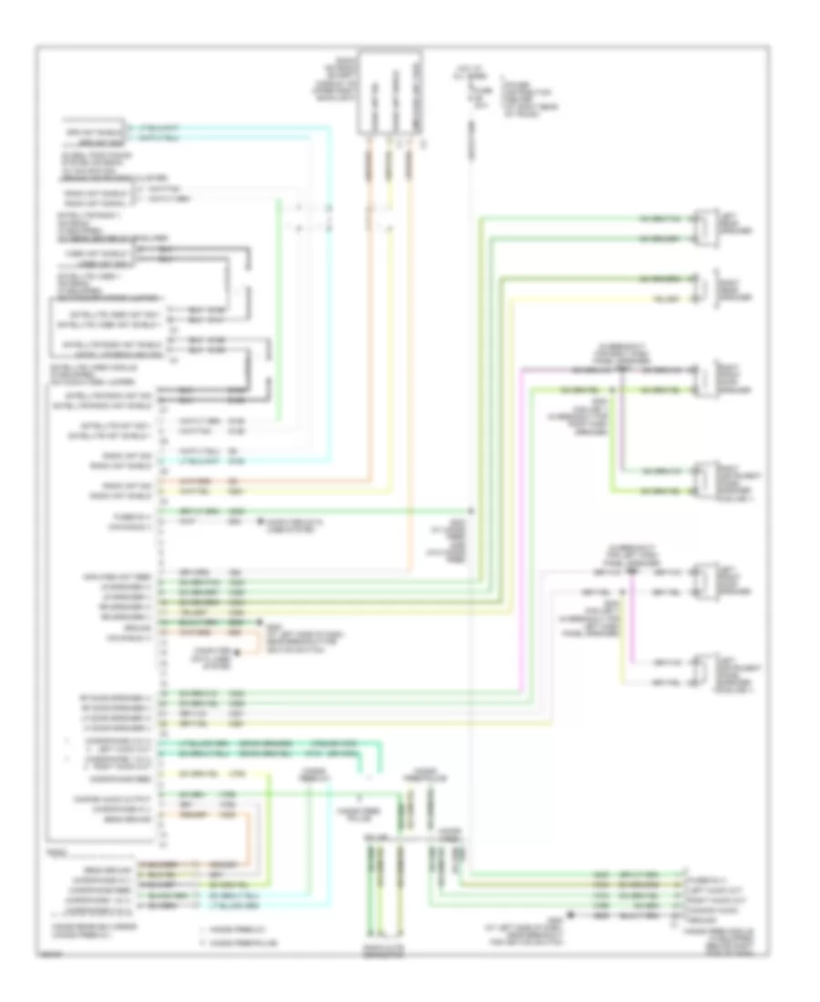 https://portal-diagnostov.com/license.html
Automotive Electricians Portal FZCO
Automotive Electricians Portal FZCO
https://portal-diagnostov.com/license.html
https://portal-diagnostov.com/license.html
Automotive Electricians Portal FZCO
Automotive Electricians Portal FZCOList of elements for Radio Wiring Diagram, Base for Dodge Charger R/T 2008:
- (in breakout for left dash panel speaker) s221
- (in breakout for right dash panel speaker) s222
- (or x703)
- (or x704)
- A300
- Amplified ant feed
- Can b bus (+)
- Can b bus (-)
- Common audio
- Common audio output
- Computer data lines system
- D106
- D108
- D126
- D128
- D141
- D54
- D55
- D931
- Fuse 20a
- Fused b (+)
- G200 (at left side of dash, near breakout for ignition switch)
- Global positioning system antenna (w/ navigation) (behind instrument cluster)
- Gps ant shield
- Gps ant sig
- Ground
- Hands free
- Hands free module (if equipped) (behind right side of dash)
- Hands free/ police
- Hands free/police
- Hands free/uc1
- Hot at all times
- Inside rearview mirror (hands free/uc1)
- Left audio out
- Left front door speaker
- Left instrument panel speaker (midline 1)
- Left rear speaker
- Lf door speaker (+)
- Lf door speaker (-)
- Lr speaker (+)
- Lr speaker (-)
- Microphone 1 in (+)
- Microphone 1 in (+) right audio out
- Microphone 2 in (+)
- Microphone 2 in (+) left audio out
- Microphone feed
- Microphone in (-)
- Police
- Power distribution center (at right rear of trunk)
- Radio
- Radio ant shield
- Radio ant shield 1
- Radio ant sig
- Radio ant signal 1
- Radio antenna (except magnum: on upper right backlight)
- Radio mute connector
- Rf door speaker (+)
- Rf door speaker (-)
- Right audio out
- Right front door speaker
- Right instrument panel speaker (midline 1)
- Right rear speaker
- Rr speaker (+)
- Rr speaker (-)
- S203 (w/ hands free) s398 (w/o hands free)
- S223 (midline 1) (in breakout for left dash panel speaker)
- S224 (midline 1) (in breakout for right dash speaker)
- Satellite ant shield 1
- Satellite ant sig 1
- Satellite radio 1 antenna (if equipped) (at rear center of headliner)
- Satellite radio ant shield
- Satellite radio ant sig
- Satellite video 1 antenna (if equipped) (on interior mirror jumper)
- Satellite video ant shield 1
- Satellite video ant sig 1
- Satellite video module (if equipped) (on audio-video jumper)
- Sens ground
- Video ant shield 1
- Video ant sig 1
- X201
- X202
- X291
- X292
- X303
- X304
- X393
- X394
- X62
- X703
- X704
- X712
- X722
- X792
- X793
- X795
- X835
- Z909
Radio Wiring Diagram, Midline (1 of 2) for Dodge Charger R/T 2008
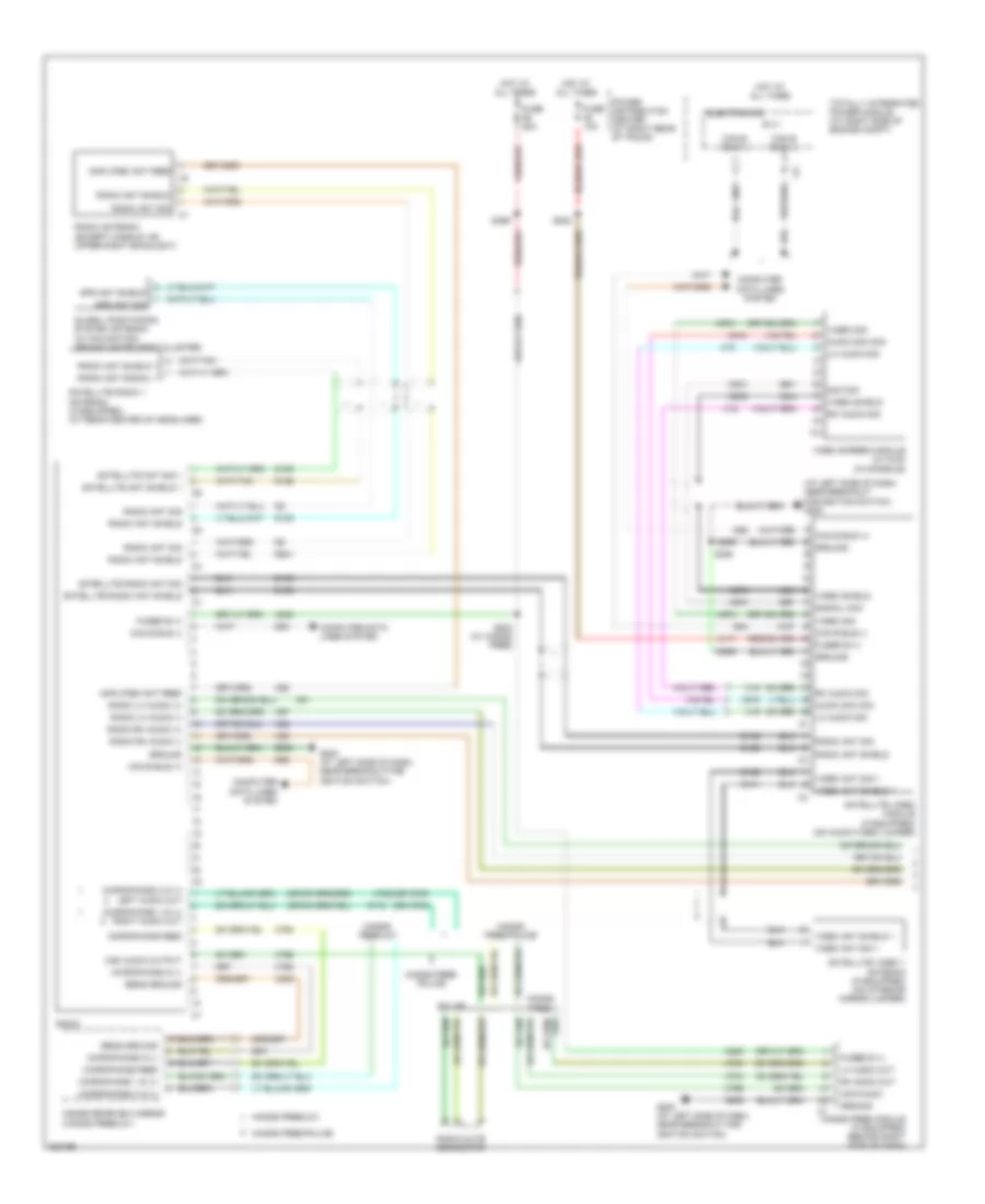 https://portal-diagnostov.com/license.html
Automotive Electricians Portal FZCO
Automotive Electricians Portal FZCO
https://portal-diagnostov.com/license.html
https://portal-diagnostov.com/license.html
Automotive Electricians Portal FZCO
Automotive Electricians Portal FZCOList of elements for Radio Wiring Diagram, Midline (1 of 2) for Dodge Charger R/T 2008:
- (at left side of dash, near breakout for ignition switch) g200
- (or x703)
- (or x704)
- A117
- A300
- Amplified ant feed
- Audio sig com
- B (+)
- Can b bus (+)
- Can b bus (-)
- Com audio
- Com audio output
- Computer data lines system
- D106
- D108
- D126
- D128
- D141
- D54
- D55
- D931
- Electronics
- Fuse 10a
- Fuse 20a
- Fused b (+)
- G200 (at left side of dash, near breakout for ignition switch)
- Global positioning system antenna (w/ navigation) (behind instrument cluster)
- Gps ant shield
- Gps ant sig
- Ground
- Hands free
- Hands free module (if equipped) (behind right side of dash)
- Hands free/ police
- Hands free/police
- Hands free/uc1
- Hot at all times
- Inside rearview mirror (hands free/uc1)
- Lh audio out
- Lh audio sig
- Microphone 1 in (+)
- Microphone 1 in (+) right audio out
- Microphone 2 in (+)
- Microphone 2 in (+) left audio out
- Microphone feed
- Microphone in (-)
- Nca
- Police
- Power distribution center (at right rear of trunk)
- Radio
- Radio ant shield
- Radio ant shield 1
- Radio ant sig
- Radio ant signal 1
- Radio antenna (except magnum: on upper right backlight)
- Radio lh audio (+)
- Radio lh audio (-)
- Radio mute connector
- Radio rh audio (+)
- Radio rh audio (-)
- Rh audio out
- Rh audio sig
- S202
- S203 (w/ hands free)
- S394
- S399
- Satellite ant shield 1
- Satellite ant sig 1
- Satellite radio 1 antenna (if equipped) (at rear center of headliner)
- Satellite radio ant shield
- Satellite radio ant sig
- Satellite video 1 antenna (if equipped) (on interior mirror jumper)
- Satellite video module (if equipped) (on audio-video jumper)
- Sens ground
- Sig com
- Signal com
- Totally integrated power module (at right side of engine compt)
- Video ant shield 1
- Video ant sig 1
- Video screen module (w/ dvd) (in console)
- Video shield
- Video sig
- X18
- X19
- X51
- X52
- X57
- X58
- X62
- X703
- X704
- X712
- X722
- X792
- X793
- X795
- X835
- X916
- X918
- X973
- X974
- X975
- Z909
Radio Wiring Diagram, Midline (2 of 2) for Dodge Charger R/T 2008
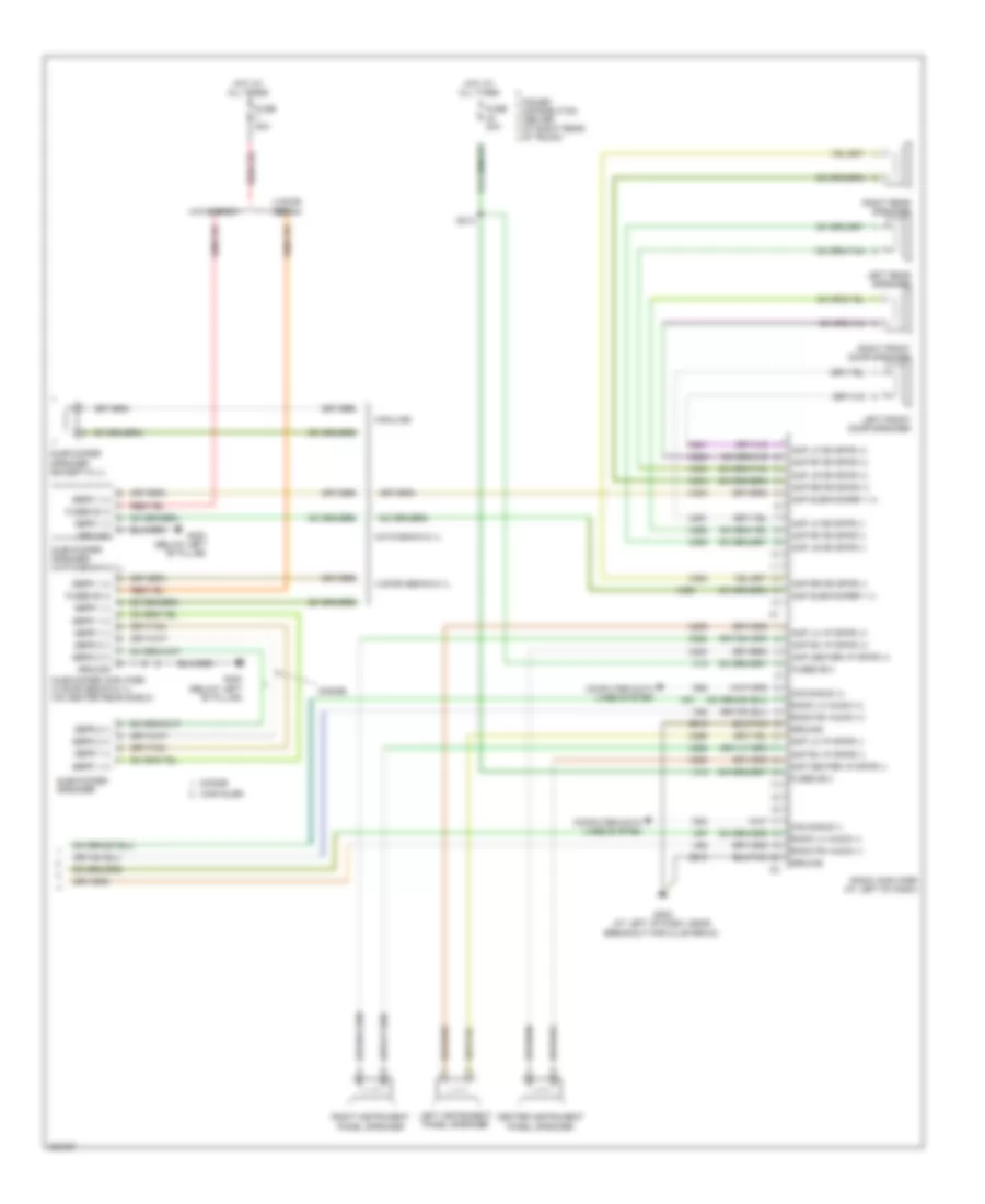 https://portal-diagnostov.com/license.html
Automotive Electricians Portal FZCO
Automotive Electricians Portal FZCO
https://portal-diagnostov.com/license.html
https://portal-diagnostov.com/license.html
Automotive Electricians Portal FZCO
Automotive Electricians Portal FZCOList of elements for Radio Wiring Diagram, Midline (2 of 2) for Dodge Charger R/T 2008:
- 4 door sedan
- 4 door sedan 6.1l
- Amp center i/p spkr (+)
- Amp center i/p spkr (-)
- Amp lf dr spkr (+)
- Amp lf dr spkr (-)
- Amp lh i/p spkr (+)
- Amp lh i/p spkr (-)
- Amp lr dr spkr (+)
- Amp lr dr spkr (-)
- Amp rf dr spkr (+)
- Amp rf dr spkr (-)
- Amp rh i/p spkr (+)
- Amp rh i/p spkr (-)
- Amp rr dr spkr (+)
- Amp rr dr spkr (-)
- Amp subwoofer 1 (+)
- Amp subwoofer 1 (-)
- Can b bus (+)
- Can b bus (-)
- Center instrument panel speaker
- Chrysler
- Computer data lines system
- D54
- D55
- Dodge
- Fuse 20a
- Fused b (+)
- Fused b(+)
- G202 (at left of dash, near breakout for cluster c3)
- G300 (below left "b" pillar)
- Ground
- Hatchback
- Hatchback 6.1l
- Highline
- Hot at all times
- Left front door speaker
- Left instrument panel speaker
- Left rear speaker
- Power distribution center (at right rear of trunk)
- Radio amplifier (at left of dash)
- Radio lh audio (+)
- Radio lh audio (-)
- Radio rh audio (+)
- Radio rh audio (-)
- Right front door speaker
- Right instrument panel speaker
- Right rear speaker
- S213
- Sbfr 1 (+)
- Sbfr 1 (-)
- Sbfr 2 (+)
- Sbfr 2 (-)
- Subwoofer amplifier (4 door sedan 6.1l) (on center rear shelf)
- Subwoofer speaker
- Subwoofer speaker (except 6.1l)
- Subwoofer speaker (hatchback 6.1l)
- X13
- X200
- X201
- X202
- X208
- X209
- X290
- X291
- X292
- X298
- X299
- X300
- X303
- X304
- X390
- X393
- X394
- X51
- X52
- X57
- X58
- Z910
Radio Wiring Diagram, Premium (1 of 3) for Dodge Charger R/T 2008
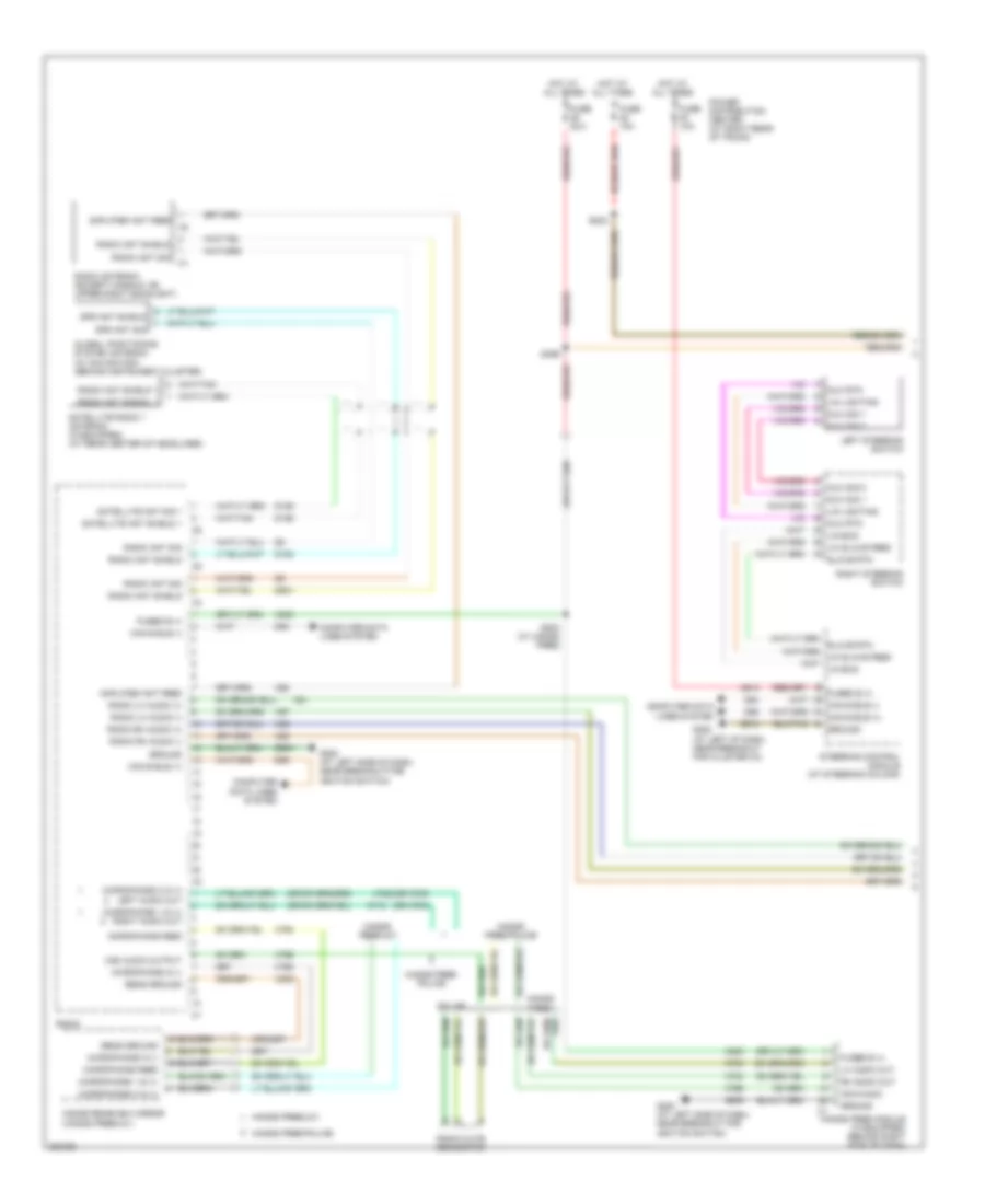 https://portal-diagnostov.com/license.html
Automotive Electricians Portal FZCO
Automotive Electricians Portal FZCO
https://portal-diagnostov.com/license.html
https://portal-diagnostov.com/license.html
Automotive Electricians Portal FZCO
Automotive Electricians Portal FZCOList of elements for Radio Wiring Diagram, Premium (1 of 3) for Dodge Charger R/T 2008:
- (or x703)
- (or x704)
- A300
- A913
- Amplified ant feed
- Can b bus (+)
- Can b bus (-)
- Com audio
- Com audio output
- Computer data lines system
- D106
- D108
- D126
- D54
- D55
- D931
- Fuse 10a
- Fuse 20a
- Fused b (+)
- G200 (at left side of dash, near breakout for ignition switch)
- G202 (at left of dash, near breakout for cluster c3)
- Global positioning system antenna (w/ navigation) (behind instrument cluster)
- Gps ant shield
- Gps ant sig
- Ground
- Hands free
- Hands free module (if equipped) (behind right side of dash)
- Hands free/ police
- Hands free/police
- Hands free/uc1
- Hot at all times
- Inside rearview mirror (hands free/uc1)
- Left steering switch
- Lh audio out
- Lin bus
- Lin lighting
- Lin slave feed
- Microphone 1 in (+)
- Microphone 1 in (+) right audio out
- Microphone 2 in (+)
- Microphone 2 in (+) left audio out
- Microphone feed
- Microphone in (-)
- Mux rtn
- Mux sig 1
- Mux sig 2
- Police
- Power distribution center (at right rear of trunk)
- Radio
- Radio ant shield
- Radio ant shield 1
- Radio ant sig
- Radio ant signal 1
- Radio antenna (except magnum: on upper right backlight)
- Radio lh audio (+)
- Radio lh audio (-)
- Radio mute connector
- Radio rh audio (+)
- Radio rh audio (-)
- Rh audio out
- Right steering switch
- S202
- S203 (w/ hands free)
- S399
- Satellite ant shield 1
- Satellite ant sig 1
- Satellite radio 1 antenna (if equipped) (at rear center of headliner)
- Sens ground
- Slave rtn
- Steering control module (at steering column)
- X51
- X52
- X57
- X58
- X62
- X703
- X704
- X712
- X722
- X792
- X793
- X795
- X835
- Z909
- Z910
Radio Wiring Diagram, Premium (2 of 3) for Dodge Charger R/T 2008
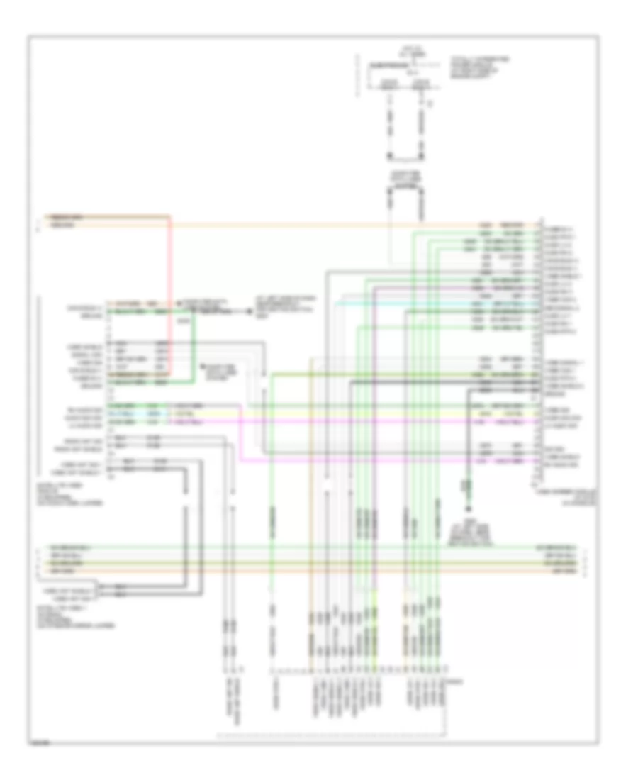 https://portal-diagnostov.com/license.html
Automotive Electricians Portal FZCO
Automotive Electricians Portal FZCO
https://portal-diagnostov.com/license.html
https://portal-diagnostov.com/license.html
Automotive Electricians Portal FZCO
Automotive Electricians Portal FZCOList of elements for Radio Wiring Diagram, Premium (2 of 3) for Dodge Charger R/T 2008:
- (at left side of dash, near breakout for ignition switch) g200
- A117
- A300
- Audio lh 1
- Audio lh 2
- Audio lh 3
- Audio rh 1
- Audio rh 2
- Audio rh 3
- Audio rtn 1
- Audio rtn 2
- Audio rtn 3
- Audio sig com
- B (+)
- Can b bus (+)
- Can b bus (-)
- Computer data lines system
- D106
- D126
- D128
- D141
- D54
- D55
- Deo signal 2
- Electronics
- Fused b (+)
- G200 (at left side of dash, near breakout for ignition switch)
- Ground
- Gruond
- Hot at all times
- Lh audio sig
- Nca
- Radio
- Radio ant shield
- Radio ant sig
- Rh audio sig
- S349
- Satellite video 1 antenna (if equipped) (on interior mirror jumper)
- Satellite video module (if equipped) (on audio-video jumper)
- Sig com
- Signal com
- Totally integrated power module (at right side of engine compt)
- Video ant shield 1
- Video ant sig 1
- Video com 1
- Video com 2
- Video screen module (w/ dvd) (in console)
- Video sheld 1
- Video shield
- Video shield 1
- Video shield 2
- Video sig
- Video signal 1
- Video signal 2
- X18
- X19
- X534
- X535
- X536
- X538
- X539
- X540
- X541
- X542
- X543
- X544
- X545
- X546
- X550
- X551
- X552
- X916
- X918
- X973
- X974
- X975
- Z909
Radio Wiring Diagram, Premium (3 of 3) for Dodge Charger R/T 2008
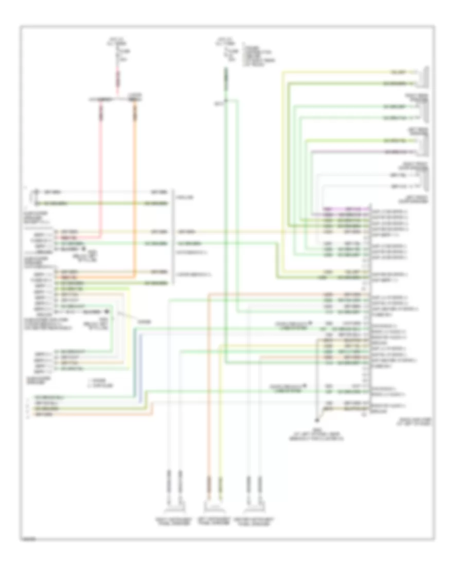 https://portal-diagnostov.com/license.html
Automotive Electricians Portal FZCO
Automotive Electricians Portal FZCO
https://portal-diagnostov.com/license.html
https://portal-diagnostov.com/license.html
Automotive Electricians Portal FZCO
Automotive Electricians Portal FZCOList of elements for Radio Wiring Diagram, Premium (3 of 3) for Dodge Charger R/T 2008:
- 4 door sedan
- 4 door sedan 6.1l
- Amp center i/p spkr (+)
- Amp center i/p spkr (-)
- Amp lf dr spkr (+)
- Amp lf dr spkr (-)
- Amp lh i/p spkr (+)
- Amp lh i/p spkr (-)
- Amp lr dr spkr (+)
- Amp lr dr spkr (-)
- Amp rf dr spkr (+)
- Amp rf dr spkr (-)
- Amp rh i/p spkr (+)
- Amp rh i/p spkr (-)
- Amp rr dr spkr (+)
- Amp rr dr spkr (-)
- Amp sbfr 1 (+)
- Amp sbfr 1 (-)
- Can b bus (+)
- Can b bus (-)
- Center instrument panel speaker
- Chrysler
- Computer data lines system
- D54
- D55
- Dodge
- Fuse 20a
- Fused b (+)
- Fused b(+)
- G202 (at left of dash, near breakout for cluster c3)
- G300 (below left "b" pillar)
- Ground
- Hatchback
- Hatchback 6.1l
- Highline
- Hot at all times
- Left front door speaker
- Left instrument panel speaker
- Left rear speaker
- Power distribution center (at right rear of trunk)
- Radio amplifier (at left of dash)
- Radio lh audio (+)
- Radio lh audio (-)
- Radio rh audio (+)
- Radio rh audio (-)
- Right front door speaker
- Right instrument panel speaker
- Right rear speaker
- S213
- Sbfr 1 (+)
- Sbfr 1 (-)
- Sbfr 2 (+)
- Sbfr 2 (-)
- Subwoofer amplifier (4 door sedan 6.1l) (on center rear shelf)
- Subwoofer speaker
- Subwoofer speaker (except 6.1l)
- Subwoofer speaker (hatchback 6.1l)
- X13
- X200
- X201
- X202
- X208
- X209
- X290
- X291
- X292
- X298
- X299
- X300
- X303
- X304
- X390
- X393
- X394
- X51
- X52
- X57
- X58
- Z910
SHIFT INTERLOCK
Shift Interlock Wiring Diagram, 4 Speed A/T for Dodge Charger R/T 2008
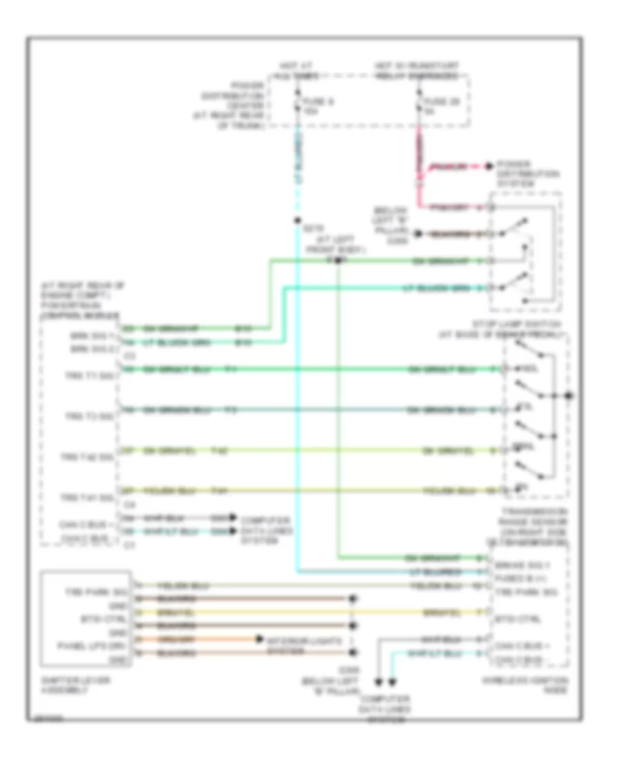 https://portal-diagnostov.com/license.html
Automotive Electricians Portal FZCO
Automotive Electricians Portal FZCO
https://portal-diagnostov.com/license.html
https://portal-diagnostov.com/license.html
Automotive Electricians Portal FZCO
Automotive Electricians Portal FZCOList of elements for Shift Interlock Wiring Diagram, 4 Speed A/T for Dodge Charger R/T 2008:
- (at left front body) s309
- (at right rear of engine compt) powertrain control module
- (below left "b" pillar)
- (below left "b" pillar) g300
- B15
- B16
- Brake sig 1
- Brk sig 1
- Brk sig 2
- Btsi ctrl
- Can c bus +
- Can c bus -
- Computer data lines system
- D64
- D65
- Fuse 29 5a
- Fuse 8 15a
- Fused b (+)
- G300
- Gnd
- Hot at all times
- Hot w/ run/start relay energized
- Interior lights system
- Nol
- P3l
- Panel lps drv
- Power distribution center (at right rear of trunk)
- Power distribution system
- Prnl
- S215
- Shifter lever assembly
- Stop lamp switch (at base of brake pedal)
- T41
- T42
- Transmission range sensor (on right side of transmission)
- Trs park sig
- Trs t1 sig
- Trs t3 sig
- Trs t41 sig
- Trs t42 sig
- Wireless ignition node
Shift Interlock Wiring Diagram, 5 Speed A/T for Dodge Charger R/T 2008
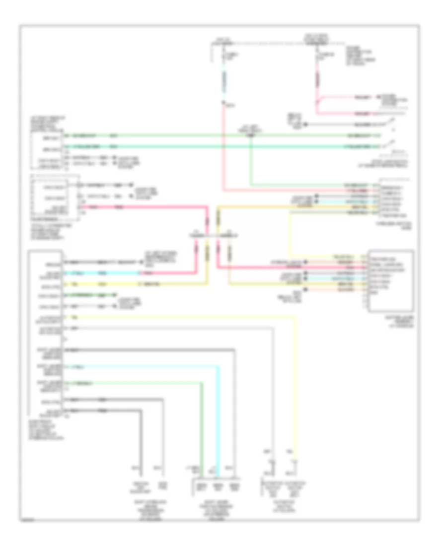 https://portal-diagnostov.com/license.html
Automotive Electricians Portal FZCO
Automotive Electricians Portal FZCO
https://portal-diagnostov.com/license.html
https://portal-diagnostov.com/license.html
Automotive Electricians Portal FZCO
Automotive Electricians Portal FZCOList of elements for Shift Interlock Wiring Diagram, 5 Speed A/T for Dodge Charger R/T 2008:
- (at left front body) s309
- (at left of dash, near breakout for cluster c3) g202
- (at right rear of engine compt) powertrain control module
- (below left "b" pillar) g300
- Autostick sw mux sig
- Autostick sw mux sply
- Autostick switch (w/ column)
- Autostick switch mux sig
- Autostick switch mux sply
- B15
- B16
- Brake sig 1
- Brk sig 1
- Brk sig 2
- Btsi ctrl
- Can c bus +
- Can c bus -
- Computer data lines system
- D64
- D65
- Electronic shift module (w/ column) (at bottom of steering column)
- Electronics
- F902
- Fuse 29 5a
- Fuse 8 15a
- Fused b (+)
- G300 (below left "b" pillar)
- Gnd
- Ground
- Hot at all times
- Hot w/ run/ start relay energized
- Ign off- run-start
- Ign off- run-start c2
- Ign off-run-start
- Ignition off- run-start
- Interior lights system
- K321
- Panel lamps drv
- Pnk
- Position sens gnd
- Position sens sig
- Position sens sply
- Power distribution center (at right rear of trunk)
- Power distribution system
- S215
- Sens gnd
- Sens sig
- Sens sply
- Shift interlock brake transmission solenoid (w/ column)
- Shift lever
- Shift lever position sensor (w/ column) (on steering column)
- Shifter lever assembly (w/ console)
- Stop lamp switch (at base of brake pedal)
- Totally integrated power module (at right side of engine compt)
- Trs park sig
- W/ column
- W/ console
- Wireless ignition node
- Z910
STARTING/CHARGING
Charging Wiring Diagram for Dodge Charger R/T 2008
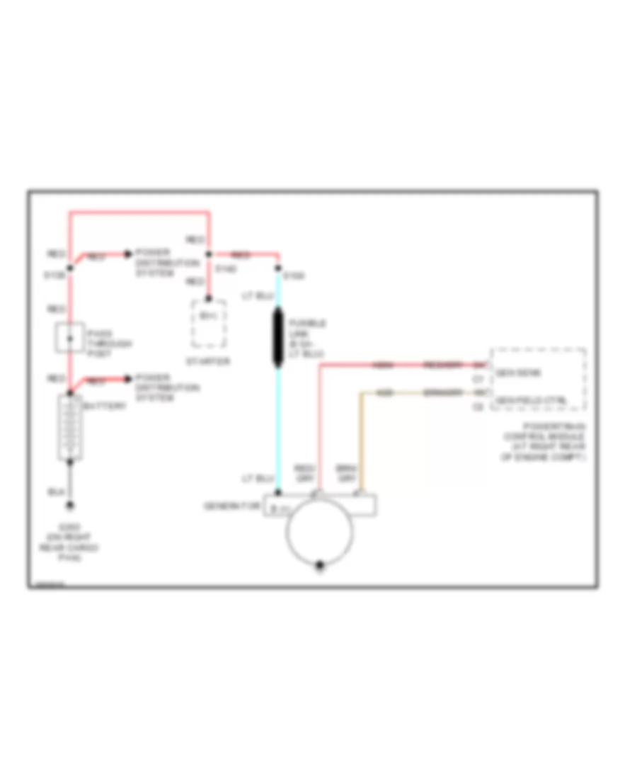 https://portal-diagnostov.com/license.html
Automotive Electricians Portal FZCO
Automotive Electricians Portal FZCO
https://portal-diagnostov.com/license.html
https://portal-diagnostov.com/license.html
Automotive Electricians Portal FZCO
Automotive Electricians Portal FZCOList of elements for Charging Wiring Diagram for Dodge Charger R/T 2008:
- A804
- B (+)
- B(+)
- Battery
- G303 (on right rear cargo pan)
- Gen field ctrl
- Gen sens
- Generator
- K20
- Pass through post
- Power distribution system
- Powertrain control module (at right rear of engine compt)
- Red
- S100
- S138
- S142
- Starter
Starting Wiring Diagram for Dodge Charger R/T 2008
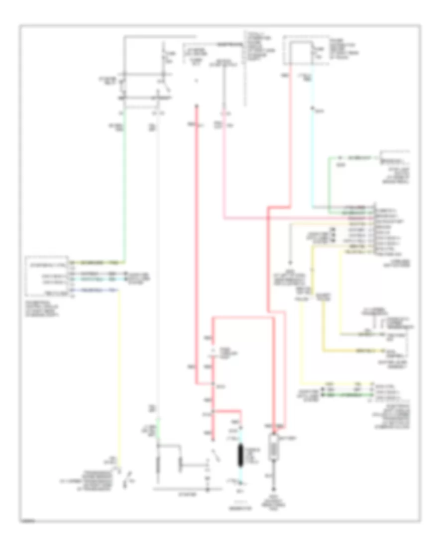 https://portal-diagnostov.com/license.html
Automotive Electricians Portal FZCO
Automotive Electricians Portal FZCO
https://portal-diagnostov.com/license.html
https://portal-diagnostov.com/license.html
Automotive Electricians Portal FZCO
Automotive Electricians Portal FZCOList of elements for Starting Wiring Diagram for Dodge Charger R/T 2008:
- 15a
- 87a
- B(+)
- Battery
- Brake sig 1
- Btsi control
- Btsi ctrl
- Can c bus (+)
- Can c bus (-)
- Can c bus (-) can c bus (+) c1
- Com-lin
- Computer data lines system
- Console w/ 5 speed transmission
- D64
- D65
- Electronic shift module (column w/ 5 speed transmission) (at bottom of steering column)
- Electronics
- Except police
- F20
- Fuse
- Fuse 25a
- Fused b (+)
- G202 (at left of dash, near breakout for cluster c3)
- G303 (on right rear cargo pan)
- Generator
- Ground
- Hold-on
- Ign run- start output
- Ign run-start
- K321
- Pass through post
- Police
- Power distribution center (at right rear of trunk)
- Powertrain control module (at right rear of engine compt)
- Pull-on
- Red
- Red a11
- S100
- S138
- S142
- S215
- S309
- Shifter lever assembly
- Starter
- Starter coil driver
- Starter relay
- Starter rly ctrl
- Stop lamp switch (at base of brake pedal)
- T41
- T752
- Totally integrated power module (at right side of engine compt)
- Transmission range sensor (w/ 4 speed transmission) (on right side of transmission)
- Trs park sig
- Trs t41 sig
- W/ 4 speed transmission
- Wireless ignition node
SUPPLEMENTAL RESTRAINTS
Supplemental Restraints Wiring Diagram (1 of 2) for Dodge Charger R/T 2008
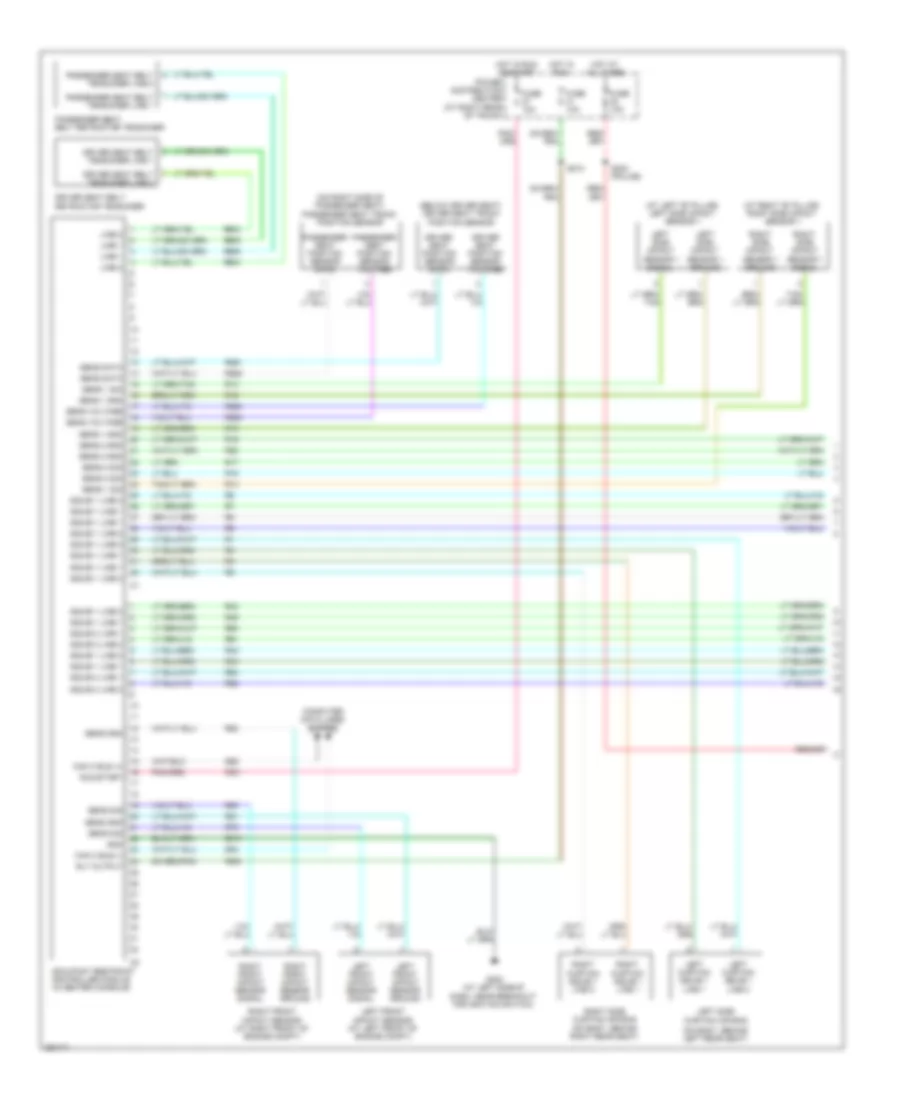 https://portal-diagnostov.com/license.html
Automotive Electricians Portal FZCO
Automotive Electricians Portal FZCO
https://portal-diagnostov.com/license.html
https://portal-diagnostov.com/license.html
Automotive Electricians Portal FZCO
Automotive Electricians Portal FZCOList of elements for Supplemental Restraints Wiring Diagram (1 of 2) for Dodge Charger R/T 2008:
- (at left "b" pillar) left side impact sensor 1
- (at right "b" pillar) right side impact sensor 1
- (below driver seat) driver seat track position sensor
- (on body, behind left rear seat)
- (on right side of passenger seat) passenger seat track position sensor
- Can c bus (+)
- Can c bus (-)
- Computer data lines system
- D64
- D65
- Driver seat belt retractor tensioner
- Driver seat belt tensioner line 1
- Driver seat belt tensioner line 2
- Driver seat position sensor data
- Driver seat position sensor voltage
- F201
- F500
- Fuse 10a
- G200 (at left side of dash, near breakout for ignition switch)
- Gnd
- Hot at all times
- Hot in run
- Hot in run or start
- Left curtain squib 1 line 1
- Left curtain squib 1 line 2
- Left front impact sensor (at left front of engine compt)
- Left front impact sensor ground
- Left front impact sensor signal
- Left side curtain air bag
- Left side impact sensor 1 ground
- Left side impact sensor 1 signal
- Line 1
- Line 2
- Occupant restraint controller module (in center console)
- Passenger seat belt retractor tensioner
- Passenger seat belt tensioner line 1
- Passenger seat belt tensioner line 2
- Passenger seat position sensor data
- Passenger seat position sensor voltage
- Power distribution center (at right rear of trunk)
- R13
- R14
- R15
- R16
- R17
- R18
- R19
- R20
- R261
- R262
- R263
- R264
- R42
- R43
- R44
- R45
- R503
- R504
- R505
- R506
- R61
- R62
- R63
- R64
- R79
- R80
- R81
- R82
- Right curtain squib 1 line 1
- Right curtain squib 1 line 2
- Right front impact sensor (at right front of engine compt)
- Right front impact sensor ground
- Right front impact sensor signal
- Right side curtain air bag (on body, behind right rear seat)
- Right side impact sensor 1 ground
- Right side impact sensor 1 signal
- Rly output
- Run/start
- S210
- S230 (police)
- Sens 1 gnd
- Sens 1 sig
- Sens 2 gnd
- Sens 2 sig
- Sens data
- Sens gnd
- Sens sig
- Sens voltage
- Squib 1 line 1
- Squib 1 line 2
- Squib 2 line 1
- Squib 2 line 2
- Z913
Supplemental Restraints Wiring Diagram (2 of 2) for Dodge Charger R/T 2008
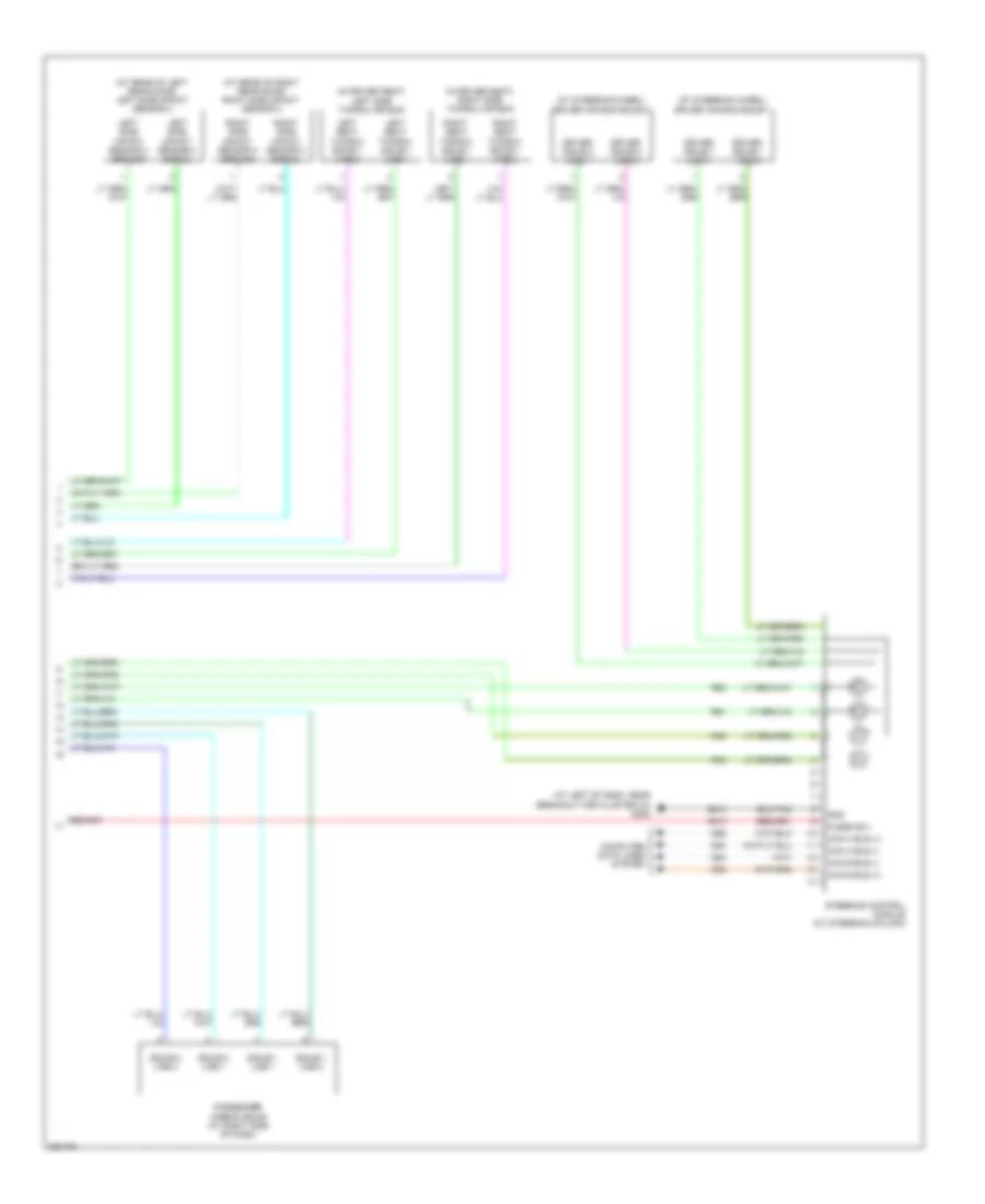 https://portal-diagnostov.com/license.html
Automotive Electricians Portal FZCO
Automotive Electricians Portal FZCO
https://portal-diagnostov.com/license.html
https://portal-diagnostov.com/license.html
Automotive Electricians Portal FZCO
Automotive Electricians Portal FZCOList of elements for Supplemental Restraints Wiring Diagram (2 of 2) for Dodge Charger R/T 2008:
- (at left of dash, near breakout for cluster c3) g202
- (at rear of left rear door) left side impact sensor 2
- (at rear of right rear door) right side impact sensor 2
- (at steering wheel) driver air bag squib 1
- (at steering wheel) driver air bag squib 2
- (in driver seat) left side thorax air bag
- (in driver seat) right side thorax air bag
- A913
- Can b bus (+)
- Can b bus (-)
- Can c bus (+)
- Can c bus (-)
- Computer data lines system
- D54
- D55
- D64
- D65
- Driver squib 1 line 1
- Driver squib 1 line 2
- Driver squib 2 line 1
- Driver squib 2 line 2
- Fused b(+)
- Gnd
- Left seat thorax squib 1 line 1
- Left seat thorax squib 1 line 2
- Left side impact sensor 2 ground
- Left side impact sensor 2 signal
- Passenger airbag squib (at right side of dash)
- R43
- R45
- R61
- R63
- Right seat thorax squib 1 line 1
- Right seat thorax squib 1 line 2
- Right side impact sensor 2 ground
- Right side impact sensor 2 signal
- Squib 1 line 1
- Squib 1 line 2
- Squib 2 line 1
- Squib 2 line 2
- Steering control module (at steering column)
- Z910
TRANSMISSION
Transmission Wiring Diagram, 4 Speed (1 of 2) for Dodge Charger R/T 2008
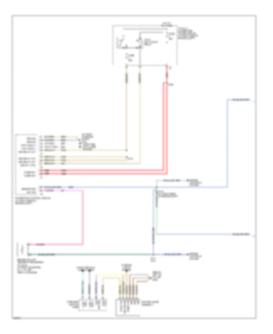 https://portal-diagnostov.com/license.html
Automotive Electricians Portal FZCO
Automotive Electricians Portal FZCO
https://portal-diagnostov.com/license.html
https://portal-diagnostov.com/license.html
Automotive Electricians Portal FZCO
Automotive Electricians Portal FZCOList of elements for Transmission Wiring Diagram, 4 Speed (1 of 2) for Dodge Charger R/T 2008:
- (at right of engine compt) g102 computer data lines system
- (at right rear of engine compt)
- (below left "b" pillar) g300
- A209
- Asd relay out
- Asd rly ctrl
- Auto shut down relay
- Btsi ctrl
- Bus - can c
- Can c bus (+)
- Can c bus (-)
- Can c bus +
- Computer data lines system
- D64
- D65
- Ect sig
- Engine controls system
- Engine coolant temperature sensor (2.7l/3.5l: at front of engine) (6.1l: at left front of engine)
- F342
- Fuse 25a
- Fused b(+)
- Gnd
- Ground
- Hot at all times
- Interior lights system
- K51
- K900
- Panel lps
- Powertrain control module (at right rear of engine compt)
- Red
- S111 (3.5l)
- S143
- S166
- Sensor gnd
- Shifter lever assembly
- Totally integrated power module (at right side of engine compt)
- Trs prk sig
- Wireless ignition node
- Z904
Transmission Wiring Diagram, 4 Speed (2 of 2) for Dodge Charger R/T 2008
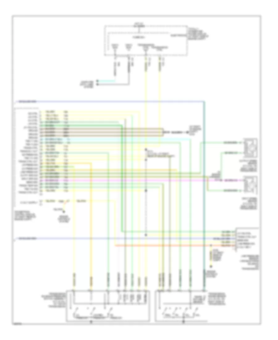 https://portal-diagnostov.com/license.html
Automotive Electricians Portal FZCO
Automotive Electricians Portal FZCO
https://portal-diagnostov.com/license.html
https://portal-diagnostov.com/license.html
Automotive Electricians Portal FZCO
Automotive Electricians Portal FZCOList of elements for Transmission Wiring Diagram, 4 Speed (2 of 2) for Dodge Charger R/T 2008:
- (at right of engine compt) g102
- (in engine harness) s113
- 2/4 ctrl
- 2/4 press sig
- 2/4 press sw
- 2/4 sol
- 5 volt sply
- Can c bus (+)
- Can c bus (-)
- Computer data lines system
- D64
- D65
- Electronics
- Engine controls system
- F856
- Fused b(+)
- Ground
- Hot at all times
- Input spd sig
- Input speed sensor (2.7l/3.5l: on right side of transmission)
- L/r ctrl
- L/r press sig
- L/r sol
- Line press sig
- Line pressure sensor/ variable force solenoid (on transmission)
- Low/rev press sw
- Lp vfs ctrl
- Nol
- Od ctrl
- Od press sig
- Od press sw
- Od sol
- Outpt spd sig
- Output speed sensor (2.7l/3.5l: on right side of transmission)
- P3l
- Powertrain control module (at right rear of engine compt)
- Prnl
- S106 (at right rear of engine compt)
- S114 (2.7l/3.5l: at right rear of engine compt)
- S115
- Sens gnd
- T118
- T13
- T14
- T15
- T16
- T19
- T20
- T38
- T41
- T42
- T47
- T50
- T52
- T54
- T59
- T60
- Tempe- rature sensor
- Totally integrated power module (at right side of engine compt)
- Trans ctrl
- Trans ctrl out
- Trans rly out
- Trans temp sig
- Transmission ctrl
- Transmission ctrl out
- Transmission range sensor (2.7l & 3.5l: on right side of transmission)
- Transmission solenoid/pressure switch assembly (2.7l & 3.5l: at top of transmission)
- Trs t1 sig
- Trs t3 sig
- Trs t41 sig
- Trs t42 sig
- Ud ctrl
- Ud sol
- Z904
Transmission Wiring Diagram, 5 Speed for Dodge Charger R/T 2008
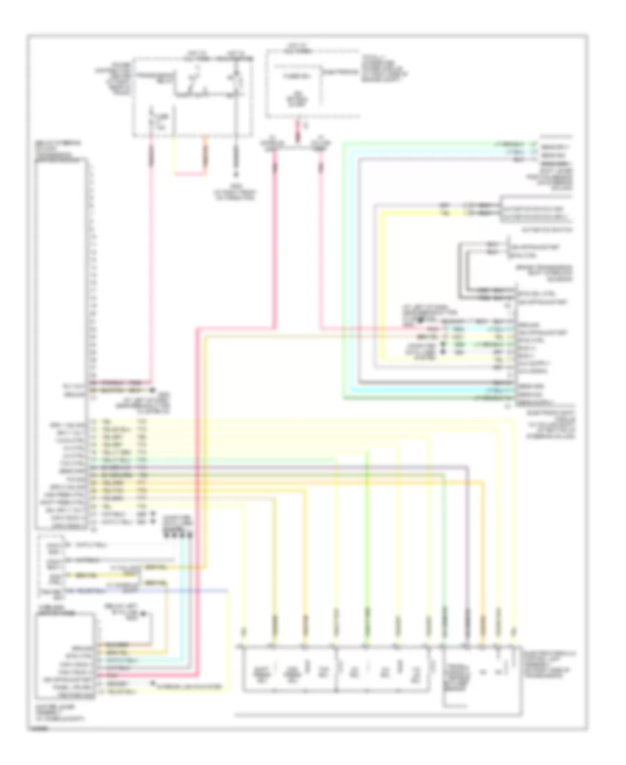 https://portal-diagnostov.com/license.html
Automotive Electricians Portal FZCO
Automotive Electricians Portal FZCO
https://portal-diagnostov.com/license.html
https://portal-diagnostov.com/license.html
Automotive Electricians Portal FZCO
Automotive Electricians Portal FZCOList of elements for Transmission Wiring Diagram, 5 Speed for Dodge Charger R/T 2008:
- (at left of dash, near breakout for cluster c3) g202
- (below left "b" pillar) g300
- (below steering column) transmission control module
- 1-2/ 4-5 sol
- 1-2/4-5 ctrl
- 2-3 ctrl
- 2-3 sol
- 3-4 ctrl
- 3-4 sol
- 87a
- Autostick sw mux sig
- Autostick sw mux sply
- Autostick switch
- Brake transmission shift interlock solenoid
- Btsi ctrl
- Btsi sol ctrl
- Bus (+)
- Bus (-)
- Can c bus (+)
- Can c bus (-)
- Can c bus +
- Can c bus -
- Computer data lines system
- D64
- D65
- Electrohydraulic control unit assembly (on right side of transmission)
- Electronic shift module (w/ column shift) (at bottom of steering column)
- Electronics
- F902
- F942
- Fuse 15a
- Fused b(+)
- G202 (at left of dash, near breakout for cluster c3)
- G302 (at right front of cargo pan)
- Ground
- Hot at all times
- Hot in run or start
- Ign off-run- start
- Ign off-run-start
- Interior lights system
- K321
- Mod pres ctrl
- Mod press sol
- Mux signal
- P/n sig
- Panel lps drv
- Pnk
- Power distribution center (at right rear of trunk)
- Rly out
- Sens gnd
- Sens sig
- Sens sply
- Shift lever position sensor (on steering column)
- Shift pres ctrl
- Shift press sol
- Shifter lever assembly (w/ console shift)
- Sol sply volt
- Spd 1 (n2) sig
- Spd 2 (n3) sig
- Sply volt
- T13
- T54
- T60
- T70
- T71
- T72
- T73
- T74
- T75
- T76
- T77
- T78
- Tcc ctrl
- Tcc sol
- Totally integrated power module (at right side of engine compt)
- Trans- mission tempe- rature sensor
- Transmission relay
- Trs park sig
- Trs prk sig
- W/ column shift
- W/ console shift
- Wireless ignition node
- Z910
TRUNK, TAILGATE, FUEL DOOR
Deck Lid Release Wiring Diagram for Dodge Charger R/T 2008
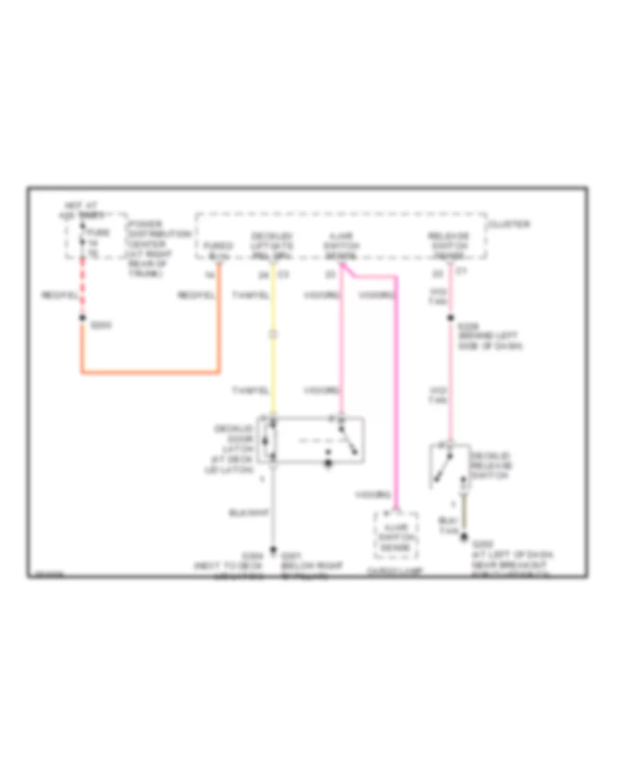 https://portal-diagnostov.com/license.html
Automotive Electricians Portal FZCO
Automotive Electricians Portal FZCO
https://portal-diagnostov.com/license.html
https://portal-diagnostov.com/license.html
Automotive Electricians Portal FZCO
Automotive Electricians Portal FZCOList of elements for Deck Lid Release Wiring Diagram for Dodge Charger R/T 2008:
- Ajar switch sense
- Cargo lamp
- Cluster
- Decklid door latch (at deck lid latch)
- Decklid release switch
- Decklid/ liftgate rel drv
- Fuse
- Fused b (+)
- G202 (at left of dash, near breakout for cluster c3)
- G301 (below right "b" pillar)
- G304 (next to deck lid latch)
- Hot at all times
- Power distribution center (at right rear of trunk)
- Release switch sense
- S200
- S228 (behind left side of dash)
WARNING SYSTEMS
Chime Wiring Diagram for Dodge Charger R/T 2008
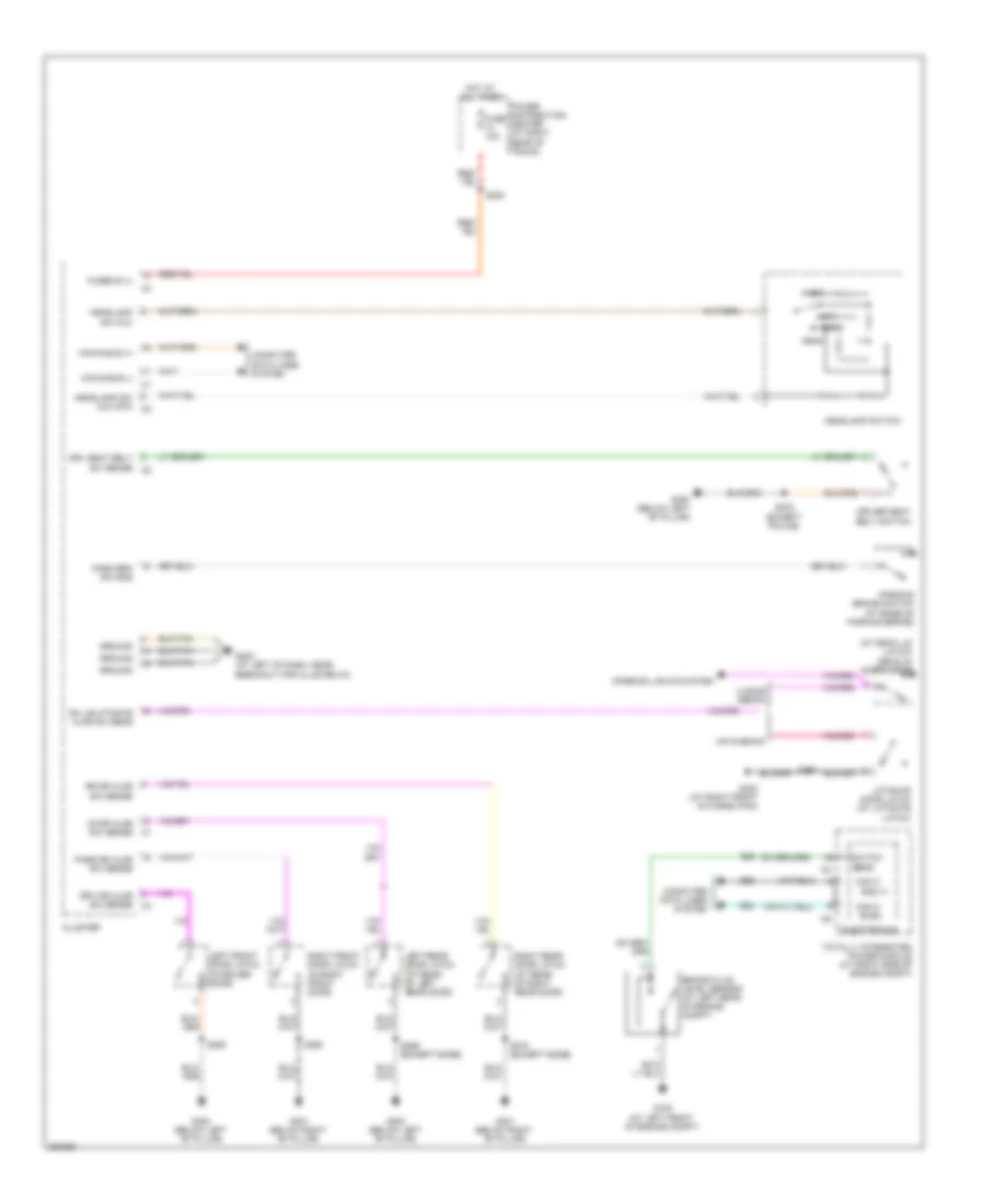 https://portal-diagnostov.com/license.html
Automotive Electricians Portal FZCO
Automotive Electricians Portal FZCO
https://portal-diagnostov.com/license.html
https://portal-diagnostov.com/license.html
Automotive Electricians Portal FZCO
Automotive Electricians Portal FZCOList of elements for Chime Wiring Diagram for Dodge Charger R/T 2008:
- (at deck lid latch) decklid door latch
- 4 door sedan
- Auto
- B20
- Brake fluid level sensor (at left rear of engine compt)
- Bus (+)
- Can b bus (+)
- Can b bus (-)
- Can c
- Can c bus(-)
- Cluster
- Computer data lines system
- D64
- D65
- Dk lid/lftgate ajar sw sens
- Driver seat belt switch
- Drv dr ajar sw sense
- Drv seat belt sw sense
- Electronics
- Fuse 10a
- Fused b (+)
- G100 (at left front of engine compt)
- G202 (at left of dash, near breakout for cluster c3)
- G300 (below left "b" pillar)
- G301 (below right "b" pillar)
- G302 (at right front of cargo pan)
- Ground
- Hatchback
- Head
- Headlamp sw mux
- Headlamp sw mux rtn
- Headlamp switch
- Hot at all times
- Interior lights system
- Left front door latch (in driver door)
- Left rear door latch (at rear of left rear door)
- Liftgate door latch (at liftgate latch)
- Lr dr ajar sw sense
- Off
- Park
- Park brk sw sns
- Parking brake switch (at base of parking brake)
- Pass dr ajar sw sense
- Power distribution center (at right rear of trunk)
- Right front door latch (in right front door)
- Right rear door latch (at rear of right rear door)
- Rr dr ajar sw sense
- S200
- S333 (except police)
- S354
- S355
- S360
- S369 (except base)
- S370 (except base)
- Sens
- Switch
- Totally integrated power module (at right side of engine compt)
Tire Pressure Monitoring Wiring Diagram for Dodge Charger R/T 2008
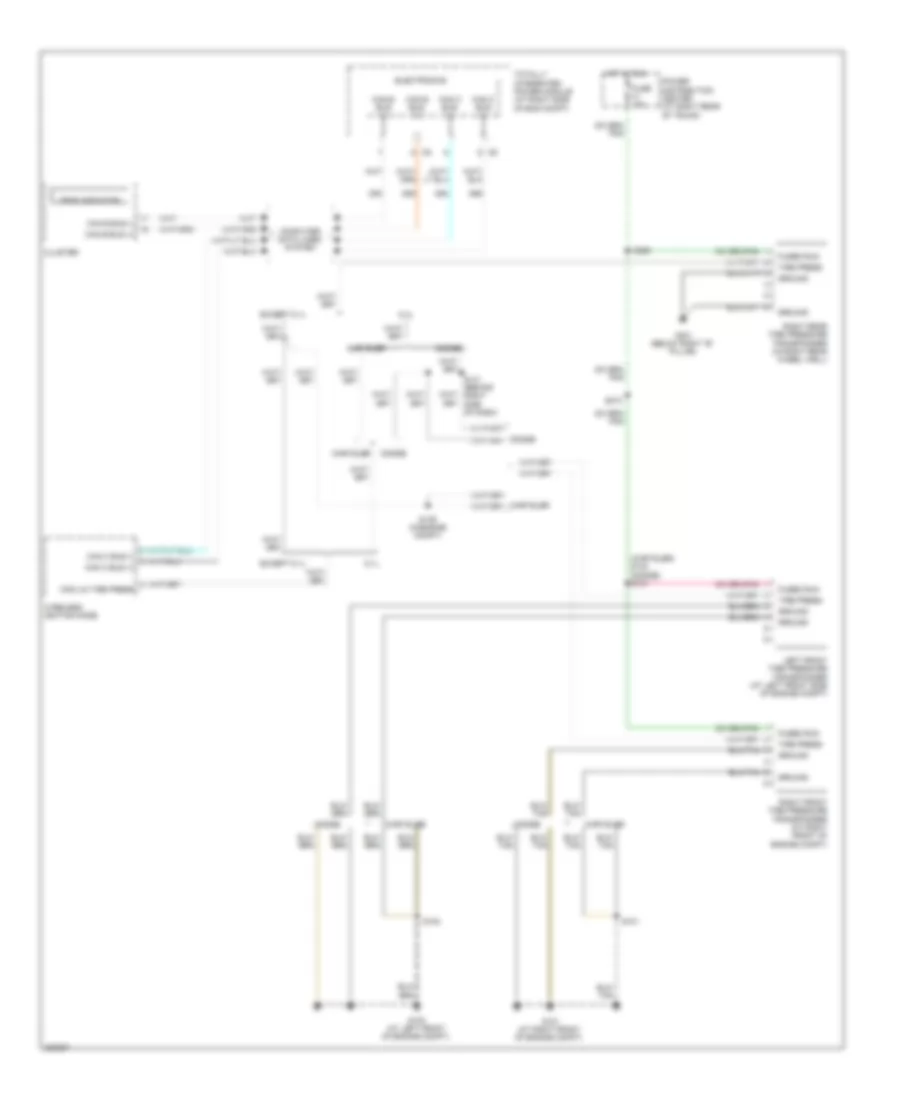 https://portal-diagnostov.com/license.html
Automotive Electricians Portal FZCO
Automotive Electricians Portal FZCO
https://portal-diagnostov.com/license.html
https://portal-diagnostov.com/license.html
Automotive Electricians Portal FZCO
Automotive Electricians Portal FZCOList of elements for Tire Pressure Monitoring Wiring Diagram for Dodge Charger R/T 2008:
- (chrysler) s140 (dodge) s131
- 6.1l
- Can b bus (+)
- Can b bus (-)
- Can b bus (-) can b bus (+)
- Can c bus (+)
- Can c bus (-)
- Chrysler
- Cluster
- Com-lin tire press
- Computer data lines system
- D54
- D55
- D64
- D65
- Dodge
- Electronics
- Except 6.1l
- Fuse 10a
- Fused run
- G100 (at left front of engine compt)
- G101 (at right front of engine compt)
- G301 (below right "b" pillar)
- Ground
- Hot in run
- Left front tire pressure transponder (at left front side of engine compt)
- Power distribution center (at right rear of trunk)
- Right front tire pressure transponder (at right front of engine compt)
- Right rear tire pressure transponder (in right rear wheel well)
- S101
- S102
- S139 (in engine compt)
- S141 (behind right side of dash)
- S210
- S326
- Tire press
- Totally integrated power module (at right side of eng compt)
- Tpms indicator
- Wireless ignition node
WIPER/WASHER
Wiper/Washer Wiring Diagram for Dodge Charger R/T 2008
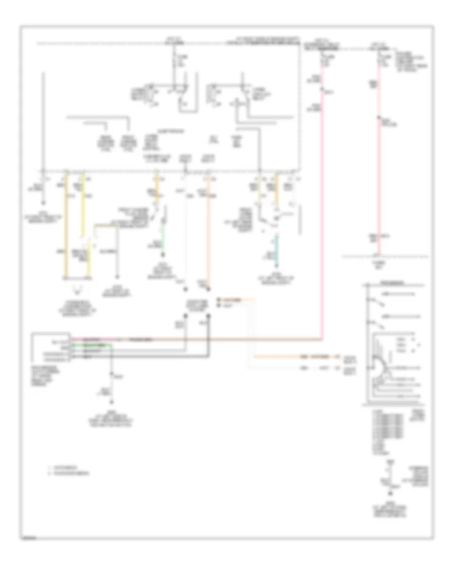 https://portal-diagnostov.com/license.html
Automotive Electricians Portal FZCO
Automotive Electricians Portal FZCO
https://portal-diagnostov.com/license.html
https://portal-diagnostov.com/license.html
Automotive Electricians Portal FZCO
Automotive Electricians Portal FZCOList of elements for Wiper/Washer Wiring Diagram for Dodge Charger R/T 2008:
- (at right side of engine compt) totally integrated power module
- 0 off 1 intermittent 2 intermittent 3 intermittent 4 intermittent 5 intermittent 6 intermittent 7 low 8 high 9 mist 10 wash
- 87a
- Can b bus (+)
- Can b bus (-)
- Computer data lines system
- D54
- D55
- Electronics
- Four door sedan
- Front washer fluid level sensor (at right front of engine compt)
- Front washer pmp mtr ctrl
- Front wiper motor (at left rear of engine compt)
- Front wiper switch
- Fuse 10a
- Fuse 30a
- Fuse 5a
- Fused b(+)
- G100 (at left front of engine compt)
- G101 (at right front of engine compt)
- G102 (at right of engine compt)
- G200 (at left side of dash, near breakout for ignition switch)
- G202 (at left of dash, near breakout for cluster c3)
- Gnd
- Hatchback
- Hot at all times
- Hot w/ accessory delay relay energized
- Park sw sen
- Power distribution center (at right rear of trunk)
- Processor
- Rain sensor (auto wipers) (at inside rear view mirror)
- Rear washer pmp mtr ctrl
- Red/ a913
- Rly ctrl
- Rly out
- S214
- S230 (police)
- S343
- Steering column module (at steering column)
- W10
- W20
- Washer fluid lvl sw sen
- Windshield washer pump (at right front of engine compt)
- Wiper high/low relay
- Wiper on/off relay
- Wiper on/off relay control

 Čeština
 Dansk
Dansk Deutsch
 Ελληνικά
 English
 English
 Español
 Suomi
Suomi Français
 Français
 עברית
עברית Hrvatski
 Magyar
 Italiano
 한국어
한국어 Nederlands
 Polski
 Português
 Português
 Română
 Русский
 Slovenčina
 Slovenščina
 Svenska
 Türkçe
 中文 (中国)
