AIR CONDITIONING
A/C Wiring Diagram for Dodge Pickup R1997 3500
 https://portal-diagnostov.com/license.html
Automotive Electricians Portal FZCO
Automotive Electricians Portal FZCO
https://portal-diagnostov.com/license.html
https://portal-diagnostov.com/license.html
Automotive Electricians Portal FZCO
Automotive Electricians Portal FZCO
List of elements for A/C Wiring Diagram for Dodge Pickup R1997 3500:
- l
- 30a
- A/c
- A/c comp clutch rly
- A/c compressor clutch
- A/c compressor clutch relay
- A/c heater control
- A/c high pressure switch (near a/c compressor)
- A/c low pressure switch
- A/c request signal
- A/c select input
- Acc
- Blower motor
- Blower motor relay (on steering column support bracket)
- Blower motor resistor block (right side of i/p)
- C13
- C20
- C22
- C23
- C90
- Def
- Fuse 10a
- Fuse b 20a
- Fuse block
- Fuse f2
- G125 (below compressor)
- G206 (i/p right center support)
- Heat
- Hi/lo
- Hot at all times
- Hot in run or start
- Ignition switch
- Interior lights system
- Max a/c
- Off
- Power distribution center
- Powertrain control module (right side of dash panel)
- Run
- S114 (engine compt harn, left side of engine compt)
- S140 (engine compt harn, left rear corner of engine compartment)
- S155 (engine compt harn, in power distribution center)
- S160 (engine compt harn, left rear corner of engine compt)
- S201 (i/p harness, in fuse block)
- S208 (i/p harn, between i/p cluster breakouts)
- S215 (i/p harn, after airbag control module breakout)
- S217 (i/p harn, near glove box breakout)
- Start
- Tan
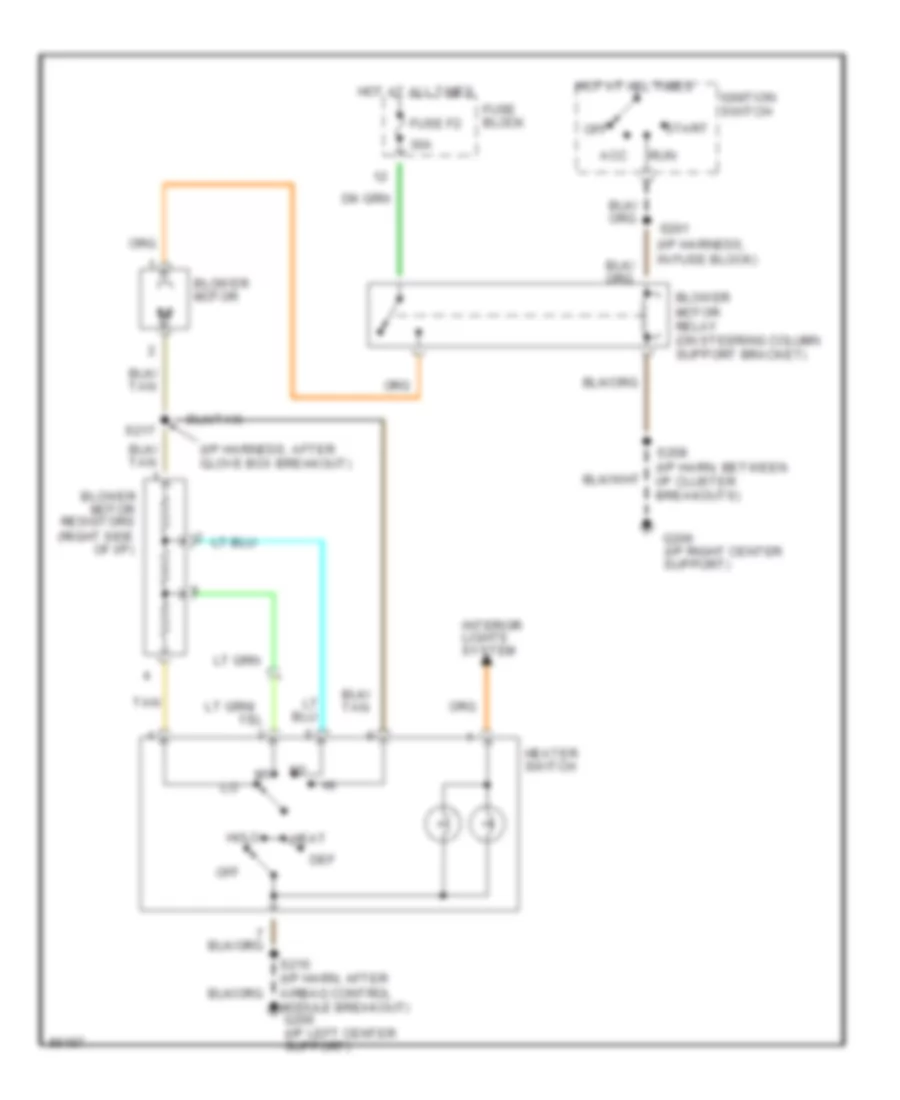
Heater Wiring Diagram for Dodge Pickup R1997 3500
 https://portal-diagnostov.com/license.html
Automotive Electricians Portal FZCO
Automotive Electricians Portal FZCO
https://portal-diagnostov.com/license.html
https://portal-diagnostov.com/license.html
Automotive Electricians Portal FZCO
Automotive Electricians Portal FZCOList of elements for Heater Wiring Diagram for Dodge Pickup R1997 3500:
- lo
- (i/p harness, after glove box breakout)
- (i/p harness, in fuse block)
- 30a
- Acc
- Blower motor
- Blower motor relay (on steering column support bracket)
- Blower motor resistors (right side of i/p)
- Def
- Fuse block
- Fuse f2
- G206 (i/p right center support)
- Heat
- Heater switch
- Hi/lo
- Hot at all times
- Ignition switch
- Interior lights system
- Off
- Run
- S201
- S208 (i/p harn, between i/p cluster breakouts)
- S215 (i/p harn, after airbag control module breakout) g206 (i/p left center support)
- S217
- Start
- Tan
ANTI-LOCK BRAKES
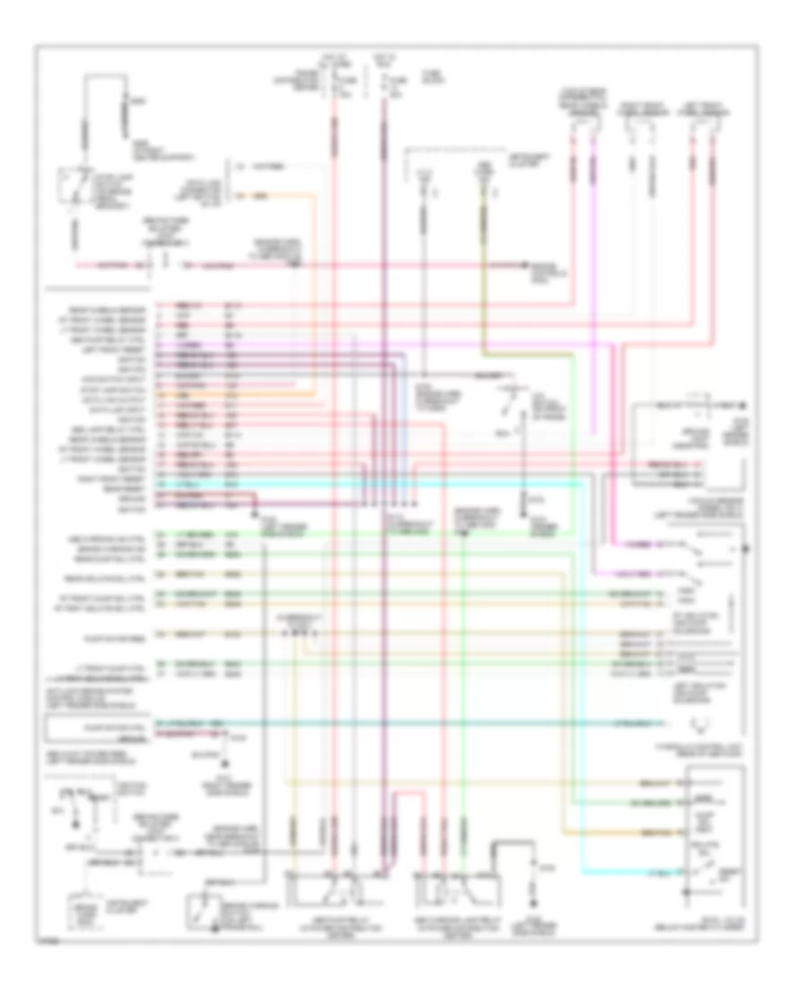
All-Wheel ABS Wiring Diagram for Dodge Pickup R1997 3500
 https://portal-diagnostov.com/license.html
Automotive Electricians Portal FZCO
Automotive Electricians Portal FZCO
https://portal-diagnostov.com/license.html
https://portal-diagnostov.com/license.html
Automotive Electricians Portal FZCO
Automotive Electricians Portal FZCOList of elements for All-Wheel ABS Wiring Diagram for Dodge Pickup R1997 3500:
- (behind knee bolster) joint connector c
- (engine harn, in breakout to abs mod) s158
- (engine harn, in breakout to abs module) s208
- (engine harn, near breakout to abs module) s109
- (in breakout to hcu) s112
- (right fender side shield)
- (top of rear differential) rear wheels sensor
- 4 x 4 ind
- 4wd switch input
- 4x4 switch (on front of frame)
- 87a
- A20
- Abs 2-way power feed (left fender side shield)
- Abs lamp relay ctrl
- Abs pump relay (in power distribution center)
- Abs pump relay ctrl
- Abs warn ind
- Abs warning ind ctrl
- Abs warning lamp relay (in power distribution center)
- Acc
- Anti-lock brake system control module (left fender side shield)
- B113
- B114
- B116
- B120
- B18
- B19
- B243
- B245
- B248
- B249
- B252
- B254
- B47
- B60
- Brake warn indic.
- Brake warning ind
- Brake warning switch (on left frame rail)
- D11
- D12
- Data link connector (left bottom of i/p)
- Data link input
- Data link output
- Dump sol
- Engine controls (pcm)
- Fuse 20a
- Fuse 40a
- Fuse block
- G100 (left fender shield)
- G100 (left fender side shield)
- G101
- G104 (fender shield)
- G107
- G19
- G206 (i/p right center support)
- Ground
- Ground joint (near pdc)
- Hot at all times
- Hot in run
- Hydraulic control unit (rear of abs pump)
- Ignition
- Ignition switch
- Instrument cluster
- Isolate sol
- Left front reset
- Left front wheel sensor
- Left isolation and dump solenoids
- Lt frnt isolate sol ctrl
- Lt front dump ctrl
- Lt front wheel sensor
- Off
- Power distribution center
- Pump motor ctrl
- Pump motor feed
- Rear dump sol ctrl
- Rear isolate sol ctrl
- Rear reset
- Rear wheels sensor
- Red
- Reset sw
- Right front reset
- Right front wheel sensor
- Rt frnt isolate sol ctrl
- Rt front dump sol ctrl
- Rt front wheel sensor
- Rt isolation and dump solenoids
- Run
- Rwal valve (below master cylinder)
- S103
- S105 (engine harn, in breakout to horn)
- S108
- S110 (in breakout to abs mod)
- S208
- Start
- Stop lamp switch
- Stop lamp switch (on brake pedal bracket)
- V40
- Vacuum sensor (diesel only) (left fender side shield)
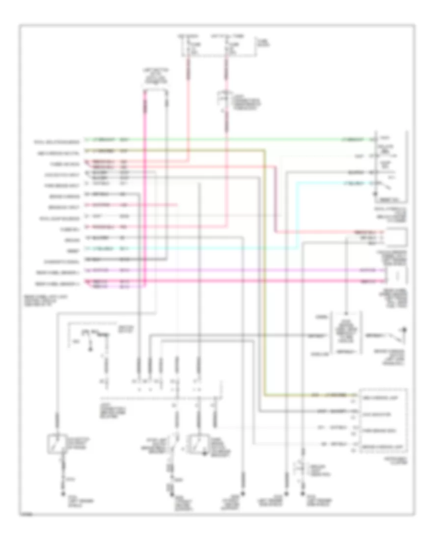
Rear Wheel ABS Wiring Diagram for Dodge Pickup R1997 3500
 https://portal-diagnostov.com/license.html
Automotive Electricians Portal FZCO
Automotive Electricians Portal FZCO
https://portal-diagnostov.com/license.html
https://portal-diagnostov.com/license.html
Automotive Electricians Portal FZCO
Automotive Electricians Portal FZCOList of elements for Rear Wheel ABS Wiring Diagram for Dodge Pickup R1997 3500:
- (left bottom of i/p) data link connector
- 4wd indicator
- 4wd switch input
- 4x4 switch (on front of frame)
- A20
- Abs warning ind ctrl
- Abs warning lamp
- Acc
- B101
- B108
- B111
- B112
- B113
- B114
- Brake sw input
- Brake warning
- Brake warning lamp
- Brake warning switch (left side frame rail)
- Diagnostic signal
- Diesel
- Dump sol
- F32
- Fuse 20a
- Fuse block
- Fused b(+)
- Fused ign (run)
- G100 (left fender side shield)
- G104 (left fender shield)
- G107
- G11
- G19
- G206 (i/p right center support)
- Gasoline
- Ground
- Ground joint (near pdc)
- Hot at all times
- Hot in run
- Ignition switch
- Instrument cluster
- Isolate sol
- Joint connector b (near rear of fuse block)
- Joint connector c (behind knee bolster)
- Off
- Park brake indic.
- Park brake input
- Park brake switch (on brake bracket)
- Rear wheel anti-lock control module (center of i/p)
- Rear wheel sensor (+)
- Rear wheel sensor (-)
- Rear wheel speed sensor (left frame rail, near fuel tank)
- Reset
- Reset sw
- Run
- Rwal dump solenoid
- Rwal hydraulic valve (below master cylinder)
- Rwal isolate solenoid
- S103
- S109 (engine harn, near breakout to abs module)
- S208
- Start
- Stop lamp switch (brake pedal bracket)
- V40
- Vacuum sensor (diesel only) (left fender side shield)
COMPUTER DATA LINES
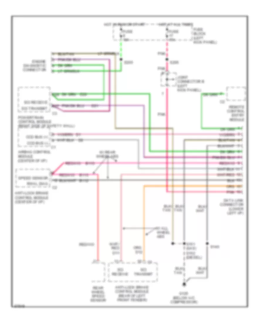
Computer Data Lines for Dodge Pickup R1997 3500
 https://portal-diagnostov.com/license.html
Automotive Electricians Portal FZCO
Automotive Electricians Portal FZCO
https://portal-diagnostov.com/license.html
https://portal-diagnostov.com/license.html
Automotive Electricians Portal FZCO
Automotive Electricians Portal FZCOList of elements for Computer Data Lines for Dodge Pickup R1997 3500:
- Airbag control module (center of i/p)
- Anti-lock brake control module (center of i/p)
- Anti-lock brake control module (rear of left front fender)
- B112
- B113
- C27
- C29
- Ccd bus (+)
- Ccd bus (-)
- D11
- D20
- D21
- Data link connector (lower left i/p)
- Engine diagnostic connector
- Fuse 10a
- Fuse 15a
- Fuse block (left kick panel)
- G125 (below a/c compressor)
- Hot at all times
- Hot in run or start
- Joint connector b (left kick panel)
- Pnk
- Powertrain control module (right side of safety wall)
- Rear wheel speed sensor
- Remote control entry module
- Rwal diag
- S140
- S151 (gas)
- S152 (diesel)
- S205
- Sci receive
- Sci transmit
- Speed sensor
- W/ all wheel abs
- W/ rear wheel abs
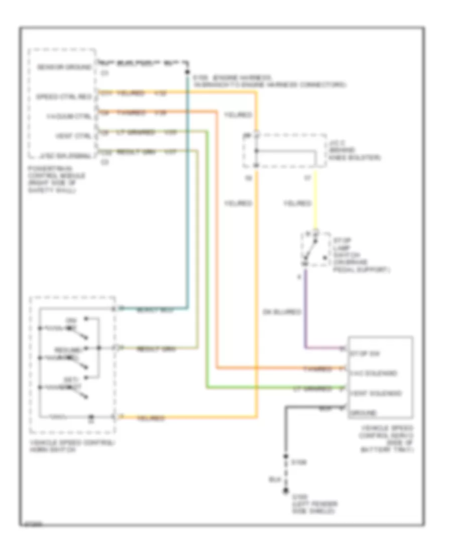
CRUISE CONTROL
Cruise Control Wiring Diagram for Dodge Pickup R1997 3500
 https://portal-diagnostov.com/license.html
Automotive Electricians Portal FZCO
Automotive Electricians Portal FZCO
https://portal-diagnostov.com/license.html
https://portal-diagnostov.com/license.html
Automotive Electricians Portal FZCO
Automotive Electricians Portal FZCOList of elements for Cruise Control Wiring Diagram for Dodge Pickup R1997 3500:
- (engine harness,
- C11
- C32
- G100 (left fender side shield)
- Ground
- J/c c (behind knee bolster)
- On/ off
- Powertrain control module (right side of safety wall)
- Resume/ accel
- S108
- S156 in branch to engine harness connectors)
- Sensor ground
- Set/ coast
- Speed ctrl res
- Stop lamp switch (on brake pedal support)
- Stop sw
- Tan/red
- V32
- V35
- V36
- V37
- Vac solenoid
- Vacuum ctrl
- Vehicle speed control servo (side of battery tray)
- Vehicle speed control/ horn switch
- Vent ctrl
- Vent solenoid
- Vsc sw signal
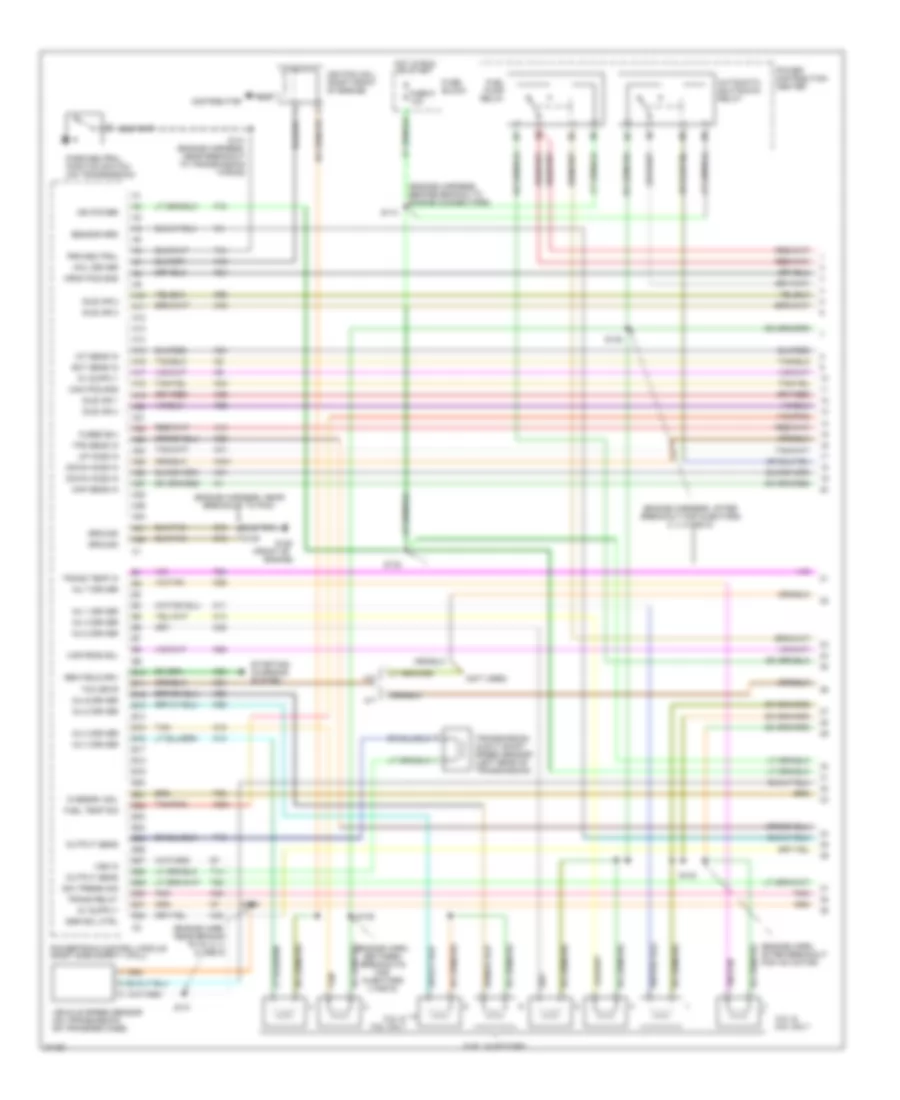
ENGINE PERFORMANCE
3.9L
3.9L, Engine Performance Wiring Diagrams (1 of 3) for Dodge Pickup R1997 3500
 https://portal-diagnostov.com/license.html
Automotive Electricians Portal FZCO
Automotive Electricians Portal FZCO
https://portal-diagnostov.com/license.html
https://portal-diagnostov.com/license.html
Automotive Electricians Portal FZCO
Automotive Electricians Portal FZCOList of elements for 3.9L, Engine Performance Wiring Diagrams (1 of 3) for Dodge Pickup R1997 3500:
- (engine harn, after breakout for iac motor)
- (engine harn, between breakouts for injectors 4 and 6)
- (engine harn, near branch to inj 2, 4, 6, and 8)
- (engine harness, after breakout for injectors 2, 4, 6 and 8)
- (engine harness, before branch to engine connectors)
- (engine harness, near breakout to pcm)
- (front of
- (not used)
- 5.2l &
- 5.2l & 5.9l only
- 5.9l only
- A/t
- A10
- A11
- A12
- A13
- A14
- A15
- A16
- A17
- A18
- A19
- A20
- A21
- A22
- A23
- A24
- A25
- A26
- A27
- A28
- A29
- A30
- A31
- A32
- Automatic shutdown relay
- B10
- B11
- B12
- B13
- B14
- B15
- B16
- B17
- B18
- B19
- B20
- B21
- B22
- B23
- B24
- B25
- B26
- B27
- B28
- B29
- B30
- B31
- B32
- Block
- Cam pos sns
- Coil driver
- Crnk pos sns
- Distributor
- Down ho2s in
- Ect sens in
- Egr sol ctrl
- Engine)
- F18
- Fuel injectors
- Fuel pump relay
- Fuel temp sig
- Fuse
- Fuse 9 10a
- Fused b(+)
- G125
- Gen field drv
- Gov press sig
- Ground
- Hot in run or start
- Iat sens in
- Idle air 1
- Idle air 2
- Idle air 3
- Idle air 4
- Ign power
- Ignition coil (right front of engine)
- Inj 1 driver
- Inj 2 driver
- Inj 3 driver
- Inj 4 driver
- Inj 5 driver
- Inj 6 driver
- Inj 7 driver
- Inj 8 driver
- K11
- K12
- K13
- K14
- K19
- K20
- K21
- K22
- K221
- K24
- K26
- K28
- K30
- K341
- K35
- K38
- K39
- K40
- K41
- K44
- K54
- K58
- K59
- K60
- K88
- M/t
- Map sens in
- Nca
- Output sens
- Overdrv sol
- Park/neutral position switch (on transmission)
- Pnk
- Power distribution center
- Powertrain control module (right side safety wall)
- Prk/neutral
- S114
- S130
- S131
- S132
- S133
- S135
- S138
- S139
- S141 (engine harness, near breakout to transmission wiring)
- Sensor grd
- Starting/ charging system
- T13
- T14
- T25
- T41
- T54
- T60
- Tan
- Tan/pnk
- Tcc drvr
- Tps sens in
- Trans relay
- Trans temp in
- Transmission ouput shaft speed sensor (left rear of transmission)
- Up ho2s in
- Var frce sol
- Vehicle speed sensor (on transmission or transfer case)
- Vss in
- Z12
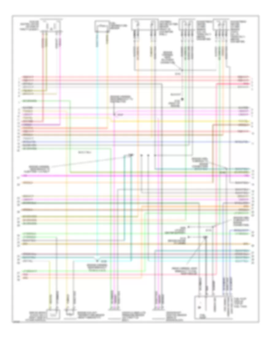
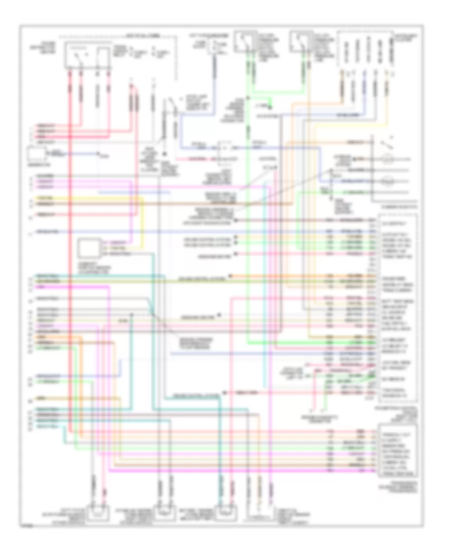
3.9L, Engine Performance Wiring Diagrams (2 of 3) for Dodge Pickup R1997 3500
 https://portal-diagnostov.com/license.html
Automotive Electricians Portal FZCO
Automotive Electricians Portal FZCO
https://portal-diagnostov.com/license.html
https://portal-diagnostov.com/license.html
Automotive Electricians Portal FZCO
Automotive Electricians Portal FZCOList of elements for 3.9L, Engine Performance Wiring Diagrams (2 of 3) for Dodge Pickup R1997 3500:
- (engine harn, in branch to engine connectors)
- (engine harness, near branch to injectors 1,3,5 and 7)
- (engine harness, near breakout to distributor)
- (engine harness, near breakout to inj 2, 4, 6, 8)
- (engine harness, near bulkhead connector)
- (rear harness, near breakout to fuel pump module)
- Crankshaft position sensor (rear of engine block)
- Downstream heated oxygen sensor (3.9/5.2/ 5.9l l/d trans only) (behind converter)
- Downstream heated oxygen sensor (5.9l h/d trans only) (behind converter)
- Egr solenoid (5.2/5.9l only) (right side of intake manifold)
- Engine coolant temperature sensor (near thermostat)
- Fuel pump
- Fuel pump module (top of fuel tank)
- Fuel signal
- Fuel temperature sensor
- G116 (brake master cylinder)
- G125 (front of engine)
- G206 (i/p right center support)
- Idle air control motor (on side of throttle body)
- Low fuel out
- Manifold absolute pressure sensor (on throttle body)
- Nca
- Pnk
- S116
- S129
- S137
- S140
- S154
- S156
- S311
- Sensor grd
- Sensor return
- Tan/pnk
- Upstream heated oxygen sensor (front of converter shell)
3.9L, Engine Performance Wiring Diagrams (3 of 3) for Dodge Pickup R1997 3500
 https://portal-diagnostov.com/license.html
Automotive Electricians Portal FZCO
Automotive Electricians Portal FZCO
https://portal-diagnostov.com/license.html
https://portal-diagnostov.com/license.html
Automotive Electricians Portal FZCO
Automotive Electricians Portal FZCOList of elements for 3.9L, Engine Performance Wiring Diagrams (3 of 3) for Dodge Pickup R1997 3500:
- (engine harn, in branch to abs controller)
- (engine harness, in branch to engine harness connectors)
- (engine harness, near breakout to ckp sensor)
- (i/p harn, near breakout for cluster)
- A/c comp rly
- A/c high pressure cutout switch (a/c high pressure line)
- A/c low pressure cutout switch (a/c low pressure line)
- A/c request
- A/c select in
- A/c system
- A142
- Air conditioning system
- Asd relay sens
- Auto sht rly
- Batt temp sens
- Battery temper- ature sensor (below battery)
- Brake sw in
- C10
- C11
- C12
- C13
- C137
- C14
- C15
- C16
- C17
- C18
- C19
- C20
- C21
- C22
- C23
- C24
- C25
- C26
- C27
- C28 c29
- C30 c31
- C32
- C90
- Camshaft position sensor (in distributor)
- Cruise control system
- Cruise feed
- Cruise sw in
- Cruise vac sol
- Cruise vnt sol
- D20
- D21
- Data link connector (left i/p)
- Duty cycle/ evap purge solenoid (rear of intake manifold)
- Engine diagnostic connector
- Evap sol drvr
- Fuel level in
- Fuel pmp rly
- Fuse 10a
- Fuse 4 30a
- Fuse 8 20a
- Fuse block
- G12
- G14
- G206 (i/p right center support)
- G21
- G24
- Gen ind drvr
- Gen ind lamp
- Generator
- Gov press sig
- Hot at all times
- Hot in run or start
- Instrument cluster
- Intake air temper- ature sensor (right side of intake manifold)
- Interior lights system
- Joint connector c (behind left knee bolster)
- K118
- K125
- K226
- K31
- K51
- K52
- K54
- K88
- Low fuel sens
- Message center
- Mil ind drvr
- Mil ind lamp
- Overdrive switch
- Overdrv ind
- Overdrv sol
- Pnk
- Power distribution center
- Powertrain control module (right side safety wall)
- Red
- S111
- S136
- S160 (engine harness, near bulkhead connector)
- S163
- S208
- S215
- Sci receive
- Sci transmit
- Sensor grd
- Sri driver
- Stop lamp switch (under left side of i/p)
- T16
- T18
- T25
- T54
- T60
- Tach signal
- Tan/red
- Tcc sol ctrl
- Throttle position sensor (side of throttle body)
- Trans overdrv
- Trans rly out
- Trans temp ind
- Trans temp sns
- Trans- mission relay
- Transmission solenoid assembly (transmission)
- Up shif ind
- V32
- V35
- V36
- V37
- V40
- Var force sol
5.2L
5.2L, Engine Performance Wiring Diagrams (1 of 3) for Dodge Pickup R1997 3500
 https://portal-diagnostov.com/license.html
Automotive Electricians Portal FZCO
Automotive Electricians Portal FZCO
https://portal-diagnostov.com/license.html
https://portal-diagnostov.com/license.html
Automotive Electricians Portal FZCO
Automotive Electricians Portal FZCOList of elements for 5.2L, Engine Performance Wiring Diagrams (1 of 3) for Dodge Pickup R1997 3500:
- (engine harn, after breakout for iac motor)
- (engine harn, between breakouts for injectors 4 and 6)
- (engine harn, near branch to inj 2, 4, 6, and 8)
- (engine harness, after breakout for injectors 2, 4, 6 and 8)
- (engine harness, before branch to engine connectors)
- (engine harness, near breakout to pcm)
- (front of
- (not used)
- 5.2l &
- 5.2l & 5.9l only
- 5.9l only
- A/t
- A10
- A11
- A12
- A13
- A14
- A15
- A16
- A17
- A18
- A19
- A20
- A21
- A22
- A23
- A24
- A25
- A26
- A27
- A28
- A29
- A30
- A31
- A32
- Automatic shutdown relay
- B10
- B11
- B12
- B13
- B14
- B15
- B16
- B17
- B18
- B19
- B20
- B21
- B22
- B23
- B24
- B25
- B26
- B27
- B28
- B29
- B30
- B31
- B32
- Block
- Cam pos sns
- Coil driver
- Crnk pos sns
- Distributor
- Down ho2s in
- Ect sens in
- Egr sol ctrl
- Engine)
- F18
- Fuel injectors
- Fuel pump relay
- Fuel temp sig
- Fuse
- Fuse 9 10a
- Fused b(+)
- G125
- Gen field drv
- Gov press sig
- Ground
- Hot in run or start
- Iat sens in
- Idle air 1
- Idle air 2
- Idle air 3
- Idle air 4
- Ign power
- Ignition coil (right front of engine)
- Inj 1 driver
- Inj 2 driver
- Inj 3 driver
- Inj 4 driver
- Inj 5 driver
- Inj 6 driver
- Inj 7 driver
- Inj 8 driver
- K11
- K12
- K13
- K14
- K19
- K20
- K21
- K22
- K221
- K24
- K26
- K28
- K30
- K341
- K35
- K38
- K39
- K40
- K41
- K44
- K54
- K58
- K59
- K60
- K88
- M/t
- Map sens in
- Nca
- Output sens
- Overdrv sol
- Park/neutral position switch (on transmission)
- Pnk
- Power distribution center
- Powertrain control module (right side safety wall)
- Prk/neutral
- S114
- S130
- S131
- S132
- S133
- S135
- S138
- S139
- S141 (engine harness, near breakout to transmission wiring)
- Sensor grd
- Starting/ charging system
- T13
- T14
- T25
- T41
- T54
- T60
- Tan
- Tan/pnk
- Tcc drvr
- Tps sens in
- Trans relay
- Trans temp in
- Transmission ouput shaft speed sensor (left rear of transmission)
- Up ho2s in
- Var frce sol
- Vehicle speed sensor (on transmission or transfer case)
- Vss in
- Z12
5.2L, Engine Performance Wiring Diagrams (2 of 3) for Dodge Pickup R1997 3500
 https://portal-diagnostov.com/license.html
Automotive Electricians Portal FZCO
Automotive Electricians Portal FZCO
https://portal-diagnostov.com/license.html
https://portal-diagnostov.com/license.html
Automotive Electricians Portal FZCO
Automotive Electricians Portal FZCOList of elements for 5.2L, Engine Performance Wiring Diagrams (2 of 3) for Dodge Pickup R1997 3500:
- (engine harn, in branch to engine connectors)
- (engine harness, near branch to injectors 1,3,5 and 7)
- (engine harness, near breakout to distributor)
- (engine harness, near breakout to inj 2, 4, 6, 8)
- (engine harness, near bulkhead connector)
- (rear harness, near breakout to fuel pump module)
- Crankshaft position sensor (rear of engine block)
- Downstream heated oxygen sensor (3.9/5.2/ 5.9l l/d trans only) (behind converter)
- Downstream heated oxygen sensor (5.9l h/d trans only) (behind converter)
- Egr solenoid (5.2/5.9l only) (right side of intake manifold)
- Engine coolant temperature sensor (near thermostat)
- Fuel pump
- Fuel pump module (top of fuel tank)
- Fuel signal
- Fuel temperature sensor
- G116 (brake master cylinder)
- G125 (front of engine)
- G206 (i/p right center support)
- Idle air control motor (on side of throttle body)
- Low fuel out
- Manifold absolute pressure sensor (on throttle body)
- Nca
- Pnk
- S116
- S129
- S137
- S140
- S154
- S156
- S311
- Sensor grd
- Sensor return
- Tan/pnk
- Upstream heated oxygen sensor (front of converter shell)
5.2L, Engine Performance Wiring Diagrams (3 of 3) for Dodge Pickup R1997 3500
 https://portal-diagnostov.com/license.html
Automotive Electricians Portal FZCO
Automotive Electricians Portal FZCO
https://portal-diagnostov.com/license.html
https://portal-diagnostov.com/license.html
Automotive Electricians Portal FZCO
Automotive Electricians Portal FZCOList of elements for 5.2L, Engine Performance Wiring Diagrams (3 of 3) for Dodge Pickup R1997 3500:
- (engine harn, in branch to abs controller)
- (engine harness, in branch to engine harness connectors)
- (engine harness, near breakout to ckp sensor)
- (i/p harn, near breakout for cluster)
- A/c comp rly
- A/c high pressure cutout switch (a/c high pressure line)
- A/c low pressure cutout switch (a/c low pressure line)
- A/c request
- A/c select in
- A/c system
- A142
- Air conditioning system
- Asd relay sens
- Auto sht rly
- Batt temp sens
- Battery temper- ature sensor (below battery)
- Brake sw in
- C10
- C11
- C12
- C13
- C137
- C14
- C15
- C16
- C17
- C18
- C19
- C20
- C21
- C22
- C23
- C24
- C25
- C26
- C27
- C28 c29
- C30 c31
- C32
- C90
- Camshaft position sensor (in distributor)
- Cruise control system
- Cruise feed
- Cruise sw in
- Cruise vac sol
- Cruise vnt sol
- D20
- D21
- Data link connector (left i/p)
- Duty cycle/ evap purge solenoid (rear of intake manifold)
- Engine diagnostic connector
- Evap sol drvr
- Fuel level in
- Fuel pmp rly
- Fuse 10a
- Fuse 4 30a
- Fuse 8 20a
- Fuse block
- G12
- G14
- G206 (i/p right center support)
- G21
- G24
- Gen ind drvr
- Gen ind lamp
- Generator
- Gov press sig
- Hot at all times
- Hot in run or start
- Instrument cluster
- Intake air temper- ature sensor (right side of intake manifold)
- Interior lights system
- Joint connector c (behind left knee bolster)
- K118
- K125
- K226
- K31
- K51
- K52
- K54
- K88
- Low fuel sens
- Message center
- Mil ind drvr
- Mil ind lamp
- Overdrive switch
- Overdrv ind
- Overdrv sol
- Pnk
- Power distribution center
- Powertrain control module (right side safety wall)
- Red
- S111
- S136
- S160 (engine harness, near bulkhead connector)
- S163
- S208
- S215
- Sci receive
- Sci transmit
- Sensor grd
- Sri driver
- Stop lamp switch (under left side of i/p)
- T16
- T18
- T25
- T54
- T60
- Tach signal
- Tan/red
- Tcc sol ctrl
- Throttle position sensor (side of throttle body)
- Trans overdrv
- Trans rly out
- Trans temp ind
- Trans temp sns
- Trans- mission relay
- Transmission solenoid assembly (transmission)
- Up shif ind
- V32
- V35
- V36
- V37
- V40
- Var force sol
5.9L
5.9L, Engine Performance Wiring Diagrams (1 of 3) for Dodge Pickup R1997 3500
 https://portal-diagnostov.com/license.html
Automotive Electricians Portal FZCO
Automotive Electricians Portal FZCO
https://portal-diagnostov.com/license.html
https://portal-diagnostov.com/license.html
Automotive Electricians Portal FZCO
Automotive Electricians Portal FZCOList of elements for 5.9L, Engine Performance Wiring Diagrams (1 of 3) for Dodge Pickup R1997 3500:
- (engine harn, after breakout for iac motor)
- (engine harn, between breakouts for injectors 4 and 6)
- (engine harn, near branch to inj 2, 4, 6, and 8)
- (engine harness, after breakout for injectors 2, 4, 6 and 8)
- (engine harness, before branch to engine connectors)
- (engine harness, near breakout to pcm)
- (front of
- (not used)
- 5.2l &
- 5.2l & 5.9l only
- 5.9l only
- A/t
- A10
- A11
- A12
- A13
- A14
- A15
- A16
- A17
- A18
- A19
- A20
- A21
- A22
- A23
- A24
- A25
- A26
- A27
- A28
- A29
- A30
- A31
- A32
- Automatic shutdown relay
- B10
- B11
- B12
- B13
- B14
- B15
- B16
- B17
- B18
- B19
- B20
- B21
- B22
- B23
- B24
- B25
- B26
- B27
- B28
- B29
- B30
- B31
- B32
- Block
- Cam pos sns
- Coil driver
- Crnk pos sns
- Distributor
- Down ho2s in
- Ect sens in
- Egr sol ctrl
- Engine)
- F18
- Fuel injectors
- Fuel pump relay
- Fuel temp sig
- Fuse
- Fuse 9 10a
- Fused b(+)
- G125
- Gen field drv
- Gov press sig
- Ground
- Hot in run or start
- Iat sens in
- Idle air 1
- Idle air 2
- Idle air 3
- Idle air 4
- Ign power
- Ignition coil (right front of engine)
- Inj 1 driver
- Inj 2 driver
- Inj 3 driver
- Inj 4 driver
- Inj 5 driver
- Inj 6 driver
- Inj 7 driver
- Inj 8 driver
- K11
- K12
- K13
- K14
- K19
- K20
- K21
- K22
- K221
- K24
- K26
- K28
- K30
- K341
- K35
- K38
- K39
- K40
- K41
- K44
- K54
- K58
- K59
- K60
- K88
- M/t
- Map sens in
- Nca
- Output sens
- Overdrv sol
- Park/neutral position switch (on transmission)
- Pnk
- Power distribution center
- Powertrain control module (right side safety wall)
- Prk/neutral
- S114
- S130
- S131
- S132
- S133
- S135
- S138
- S139
- S141 (engine harness, near breakout to transmission wiring)
- Sensor grd
- Starting/ charging system
- T13
- T14
- T25
- T41
- T54
- T60
- Tan
- Tan/pnk
- Tcc drvr
- Tps sens in
- Trans relay
- Trans temp in
- Transmission ouput shaft speed sensor (left rear of transmission)
- Up ho2s in
- Var frce sol
- Vehicle speed sensor (on transmission or transfer case)
- Vss in
- Z12
5.9L, Engine Performance Wiring Diagrams (2 of 3) for Dodge Pickup R1997 3500
 https://portal-diagnostov.com/license.html
Automotive Electricians Portal FZCO
Automotive Electricians Portal FZCO
https://portal-diagnostov.com/license.html
https://portal-diagnostov.com/license.html
Automotive Electricians Portal FZCO
Automotive Electricians Portal FZCOList of elements for 5.9L, Engine Performance Wiring Diagrams (2 of 3) for Dodge Pickup R1997 3500:
- (engine harn, in branch to engine connectors)
- (engine harness, near branch to injectors 1,3,5 and 7)
- (engine harness, near breakout to distributor)
- (engine harness, near breakout to inj 2, 4, 6, 8)
- (engine harness, near bulkhead connector)
- (rear harness, near breakout to fuel pump module)
- Crankshaft position sensor (rear of engine block)
- Downstream heated oxygen sensor (3.9/5.2/ 5.9l l/d trans only) (behind converter)
- Downstream heated oxygen sensor (5.9l h/d trans only) (behind converter)
- Egr solenoid (5.2/5.9l only) (right side of intake manifold)
- Engine coolant temperature sensor (near thermostat)
- Fuel pump
- Fuel pump module (top of fuel tank)
- Fuel signal
- Fuel temperature sensor
- G116 (brake master cylinder)
- G125 (front of engine)
- G206 (i/p right center support)
- Idle air control motor (on side of throttle body)
- Low fuel out
- Manifold absolute pressure sensor (on throttle body)
- Nca
- Pnk
- S116
- S129
- S137
- S140
- S154
- S156
- S311
- Sensor grd
- Sensor return
- Tan/pnk
- Upstream heated oxygen sensor (front of converter shell)
5.9L, Engine Performance Wiring Diagrams (3 of 3) for Dodge Pickup R1997 3500
 https://portal-diagnostov.com/license.html
Automotive Electricians Portal FZCO
Automotive Electricians Portal FZCO
https://portal-diagnostov.com/license.html
https://portal-diagnostov.com/license.html
Automotive Electricians Portal FZCO
Automotive Electricians Portal FZCOList of elements for 5.9L, Engine Performance Wiring Diagrams (3 of 3) for Dodge Pickup R1997 3500:
- (engine harn, in branch to abs controller)
- (engine harness, in branch to engine harness connectors)
- (engine harness, near breakout to ckp sensor)
- (i/p harn, near breakout for cluster)
- A/c comp rly
- A/c high pressure cutout switch (a/c high pressure line)
- A/c low pressure cutout switch (a/c low pressure line)
- A/c request
- A/c select in
- A/c system
- A142
- Air conditioning system
- Asd relay sens
- Auto sht rly
- Batt temp sens
- Battery temper- ature sensor (below battery)
- Brake sw in
- C10
- C11
- C12
- C13
- C137
- C14
- C15
- C16
- C17
- C18
- C19
- C20
- C21
- C22
- C23
- C24
- C25
- C26
- C27
- C28 c29
- C30 c31
- C32
- C90
- Camshaft position sensor (in distributor)
- Cruise control system
- Cruise feed
- Cruise sw in
- Cruise vac sol
- Cruise vnt sol
- D20
- D21
- Data link connector (left i/p)
- Duty cycle/ evap purge solenoid (rear of intake manifold)
- Engine diagnostic connector
- Evap sol drvr
- Fuel level in
- Fuel pmp rly
- Fuse 10a
- Fuse 4 30a
- Fuse 8 20a
- Fuse block
- G12
- G14
- G206 (i/p right center support)
- G21
- G24
- Gen ind drvr
- Gen ind lamp
- Generator
- Gov press sig
- Hot at all times
- Hot in run or start
- Instrument cluster
- Intake air temper- ature sensor (right side of intake manifold)
- Interior lights system
- Joint connector c (behind left knee bolster)
- K118
- K125
- K226
- K31
- K51
- K52
- K54
- K88
- Low fuel sens
- Message center
- Mil ind drvr
- Mil ind lamp
- Overdrive switch
- Overdrv ind
- Overdrv sol
- Pnk
- Power distribution center
- Powertrain control module (right side safety wall)
- Red
- S111
- S136
- S160 (engine harness, near bulkhead connector)
- S163
- S208
- S215
- Sci receive
- Sci transmit
- Sensor grd
- Sri driver
- Stop lamp switch (under left side of i/p)
- T16
- T18
- T25
- T54
- T60
- Tach signal
- Tan/red
- Tcc sol ctrl
- Throttle position sensor (side of throttle body)
- Trans overdrv
- Trans rly out
- Trans temp ind
- Trans temp sns
- Trans- mission relay
- Transmission solenoid assembly (transmission)
- Up shif ind
- V32
- V35
- V36
- V37
- V40
- Var force sol
EXTERIOR LIGHTS
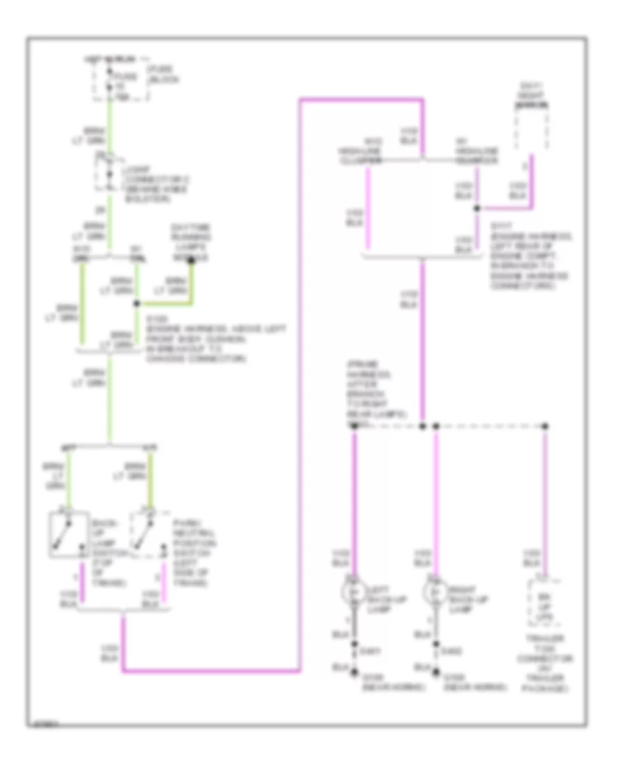
Back-up Lamps Wiring Diagram for Dodge Pickup R1997 3500
 https://portal-diagnostov.com/license.html
Automotive Electricians Portal FZCO
Automotive Electricians Portal FZCO
https://portal-diagnostov.com/license.html
https://portal-diagnostov.com/license.html
Automotive Electricians Portal FZCO
Automotive Electricians Portal FZCOList of elements for Back-up Lamps Wiring Diagram for Dodge Pickup R1997 3500:
- (frame harness, after branch to right rear lamps) s313
- A/t
- Back- up lamp switch (top of trans)
- Bk up lps
- Day/ night mirror
- Daytime running lamps module
- Fuse 10a
- Fuse block
- G100 (near horns)
- Hot in run
- Joint connector c (behind knee bolster)
- Left back-up lamp
- M/t
- Park/ neutral position switch (left side of trans)
- Right back-up lamp
- S117 (engine harness, left rear of engine compt, in branch to engine harness connectors)
- S120 (engine harness, above left front body cushion, in breakout to chassis connector)
- S401
- S402
- Trailer tow connector (w/ trailer package)
- W/ drl
- W/ high-line cluster
- W/o drl
- W/o high-line cluster
Exterior Lamps Wiring Diagram (1 of 2) for Dodge Pickup R1997 3500
 https://portal-diagnostov.com/license.html
Automotive Electricians Portal FZCO
Automotive Electricians Portal FZCO
https://portal-diagnostov.com/license.html
https://portal-diagnostov.com/license.html
Automotive Electricians Portal FZCO
Automotive Electricians Portal FZCOList of elements for Exterior Lamps Wiring Diagram (1 of 2) for Dodge Pickup R1997 3500:
- (engine harn, in break- out for left turn signal lamp) s123
- (engine harn, in break- out for right turn signal lamp) s102
- (engine harness, after branch for horn breakout) s106
- (frame harn, in break- out to trailer conn) s316
- (frame harn, in breakout to trailer connector)
- (frame harness, after branch to right rear lamps) s314
- (no connection)
- Center high mounted stop lamp 1
- Center high mounted stop lamp 2
- Fog lamp relay
- Fuse 18 15a
- Fuse 20 20a
- Fuse 6 20a
- Fuse block
- Fuse c 20a
- G100 (left front fender side shield)
- G100 (near horns)
- G104 (left fender shield)
- G206 (i/p right center support)
- G308 (below left rear speaker)
- Ground joint (near pdc)
- Hazard
- Hazard warning flasher (in fuse box)
- Head
- Headlamp switch
- Hot at all times
- Hot in acc or run
- Instrument cluster
- Joint connector a (rear of fuse block)
- Joint connector b (near rear of fuse block)
- Left license lamp
- Left park/turn signal lamp
- Left tail/ stop & turn signal lamp
- Left turn
- Left turn ind
- Normal
- Off
- Park
- Pnk/red
- Power distribution center
- Right license lamp
- Right park/turn signal lamp
- Right tail/ stop & turn signal lamp
- Right turn
- Right turn ind
- S103
- S115
- S206
- S207 (i/p harness, between breakouts for cluster conn- tan ectors)
- S312
- S315
- S401
- S402
- Seatbelt switch
- Stop lamp switch (on brake pedal arm)
- Turn signal and hazard flasher switch (part of multi- function switch, located on steering column)
- Turn signal flasher (in fuse box)
- W/ dual rear wheels
- W/ trailer tow
- W/o dual rear wheels
- W/o trailer tow
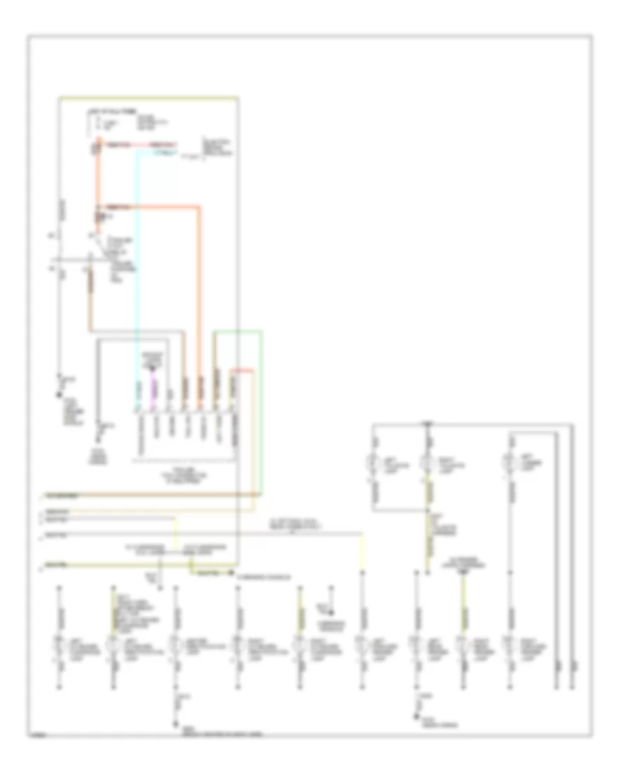
Exterior Lamps Wiring Diagram (2 of 2) for Dodge Pickup R1997 3500
 https://portal-diagnostov.com/license.html
Automotive Electricians Portal FZCO
Automotive Electricians Portal FZCO
https://portal-diagnostov.com/license.html
https://portal-diagnostov.com/license.html
Automotive Electricians Portal FZCO
Automotive Electricians Portal FZCOList of elements for Exterior Lamps Wiring Diagram (2 of 2) for Dodge Pickup R1997 3500:
- (in fender lamps harness) s406
- Back-up
- Backup lamps circuit
- Center identification lamp
- Electric brake provision
- Fuse 7 40a
- Fused b+
- G100 (left fender side shield)
- G100 (near horns)
- G908 (front center of headliner)
- Ground
- Hot at all times
- Left forward fender lamp
- Left license lamp
- Left outboard clearance lamp
- Left outboard identification lamp
- Left rear fender lamp
- Left tailgate lamp
- Left turn
- Overhead console
- Power distribution center
- Red/tan
- Right forward fender lamp
- Right outboard clearance lamp
- Right outboard identification lamp
- Right rear fender lamp
- Right tailgate lamp
- Right turn
- S108
- S119
- S312
- S317 (roof harn, after break- out for left outboard clearance lamp)
- S318
- S405
- S407 (in tailgate harness)
- S408
- Tail lps
- Tan red/
- Trailer brake
- Trailer tow connector (if equipped)
- Trailer tow relay (w/ trailer package) (in pdc)
- Tt out
- W/ clearance & id lamps
- W/ optional dual rear wheels only
- W/o clearance & id lamps
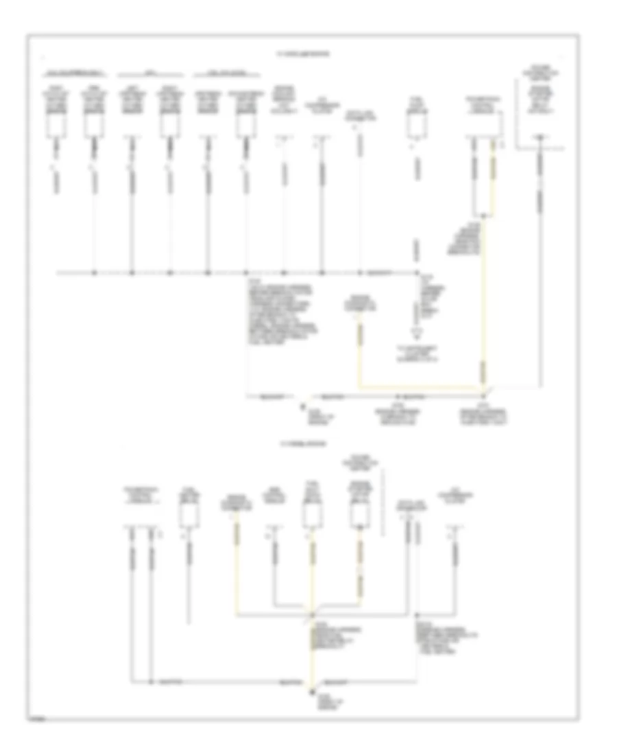
GROUND DISTRIBUTION
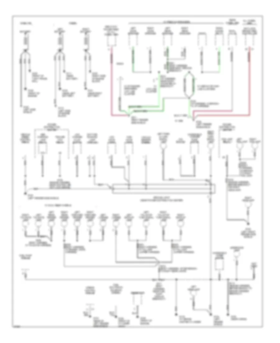
Ground Distribution Wiring Diagram (1 of 3) for Dodge Pickup R1997 3500
 https://portal-diagnostov.com/license.html
Automotive Electricians Portal FZCO
Automotive Electricians Portal FZCO
https://portal-diagnostov.com/license.html
https://portal-diagnostov.com/license.html
Automotive Electricians Portal FZCO
Automotive Electricians Portal FZCOList of elements for Ground Distribution Wiring Diagram (1 of 3) for Dodge Pickup R1997 3500:
- (left side of engine block)
- (near left battery)
- (not used)
- 4x4 switch
- 87a
- Abs 2-way power feed (w/ all wheel abs)
- Abs warning lamp relay
- Airbag control module
- All wheel abs
- Anti-lock brake (abs) controller
- Battery
- Before breakout for right headlamp)
- Daytime running lamp module
- Diesel
- Fog lamp relay 1
- Fuel pump module
- Fuel shutdown solenoid (diesel)
- G100
- G100 (front of tight frame rail)
- G100 (left fender side shield)
- G100 (left front fender side shield)
- G100 (left side shield)
- G100 (near horns)
- G101 (near right battery)
- G101 (right fender side shield)
- G104 (left fender shield)
- G104 (rear of left fender side shield)
- G111 (near battery)
- G112
- G116 (at brake master cylinder)
- G120 (right side of engine block)
- G125 (front of cylinder head)
- G125 (front of engine)
- G408 (body harness, in tailgate harness)
- Gasoline
- Generator
- Ground joint (near power distribution center)
- High note horn
- In branch to right fog lamp)
- Left backup lamp
- Left battery
- Left door speaker
- Left fog lamp
- Left forward fender lamp
- Left headlamp
- Left license lamp
- Left park & turn signal lamp
- Left rear fender lamp
- Left rear speaker
- Left tail/stop turn signal lamp
- Left tailgate lamp
- Low note horn
- Low washer fluid switch
- Power distribution center
- Radio
- Radio choke relay
- Rear wheel abs
- Right backup lamp
- Right battery
- Right door speaker
- Right fog lamp
- Right forward fender lamp
- Right headlamp
- Right license lamp
- Right park/ turn signal lamp
- Right rear fender lamp
- Right rear speaker
- Right tail/stop turn signal lamp
- Right tailgate lamp
- Rwal valve
- S108 (engine harness, near controller anti-lock brake)
- S115 (engine harness, before branch to engine harness breakout)
- S122 (i/p harness, in branch to i/p harness)
- S212 (i/p harness, near radio choke relay breakout)
- S301 (body harness, near body ground breakout)
- S311 (body harness, near fuel pump module breakout)
- S312 (body harness, after branch to right rear lamps)
- Trailer tow relay
- Underhood lamp
- Vacuum sensor (diesel)
- Vehicle speed control servo
- W/ abs
- W/ dual rear wheels
- W/ low-line cluster
- W/ medium or high- line clusters
- W/ premium speakers
- W/ standard speakers/ low line cluster
- Windshield washer pump motor
- Windshield wiper motor
Ground Distribution Wiring Diagram (2 of 3) for Dodge Pickup R1997 3500
 https://portal-diagnostov.com/license.html
Automotive Electricians Portal FZCO
Automotive Electricians Portal FZCO
https://portal-diagnostov.com/license.html
https://portal-diagnostov.com/license.html
Automotive Electricians Portal FZCO
Automotive Electricians Portal FZCOList of elements for Ground Distribution Wiring Diagram (2 of 3) for Dodge Pickup R1997 3500:
-
-
-
- downstream heated oxygen sensor
- 3.9l, 5.2l & 5.9l
- 8.0l
- 8.0l california only
- A/c compressor clutch
- A31
- A32
- Data link connector
- Egr control module
- Engine coolant sending unit (8.0l only)
- Engine diagnostic connector
- Engine starter motor relay
- Engine starter motor relay (m/t only)
- Fuel heater relay
- Fuel pump module
- Fuel shut down relay
- G125 (front of engine)
- Left upstream heated oxygen sensor
- Nca
- Post catalyst heated oxygen sensor
- Power distribution center
- Powertrain control module
- Pre- catalyst heated oxygen sensor
- Right upstream heated oxygen sensor
- S116 (i/p harness, before glove box break- out)
- S139 (engine harness, near pcm connector breakouts)
- S140 (v6/v8: engine harness, before breakouts for headlamp & dash harness connectors) (v10: engine harness, after branch to injectors 1/3/5/7/9) (diesel: engine harness, between breakouts for intake air heaters & fuel heater)
- S150 (engine harness, in branch to ground g125)
- S151 (engine harness, after branch to injectors 1/3/5/7)
- To instrument cluster (diagram 3 of 3)
- Upstream heated oxygen sensor
- W/ diesel engine
- W/ gasoline engine
Ground Distribution Wiring Diagram (3 of 3) for Dodge Pickup R1997 3500
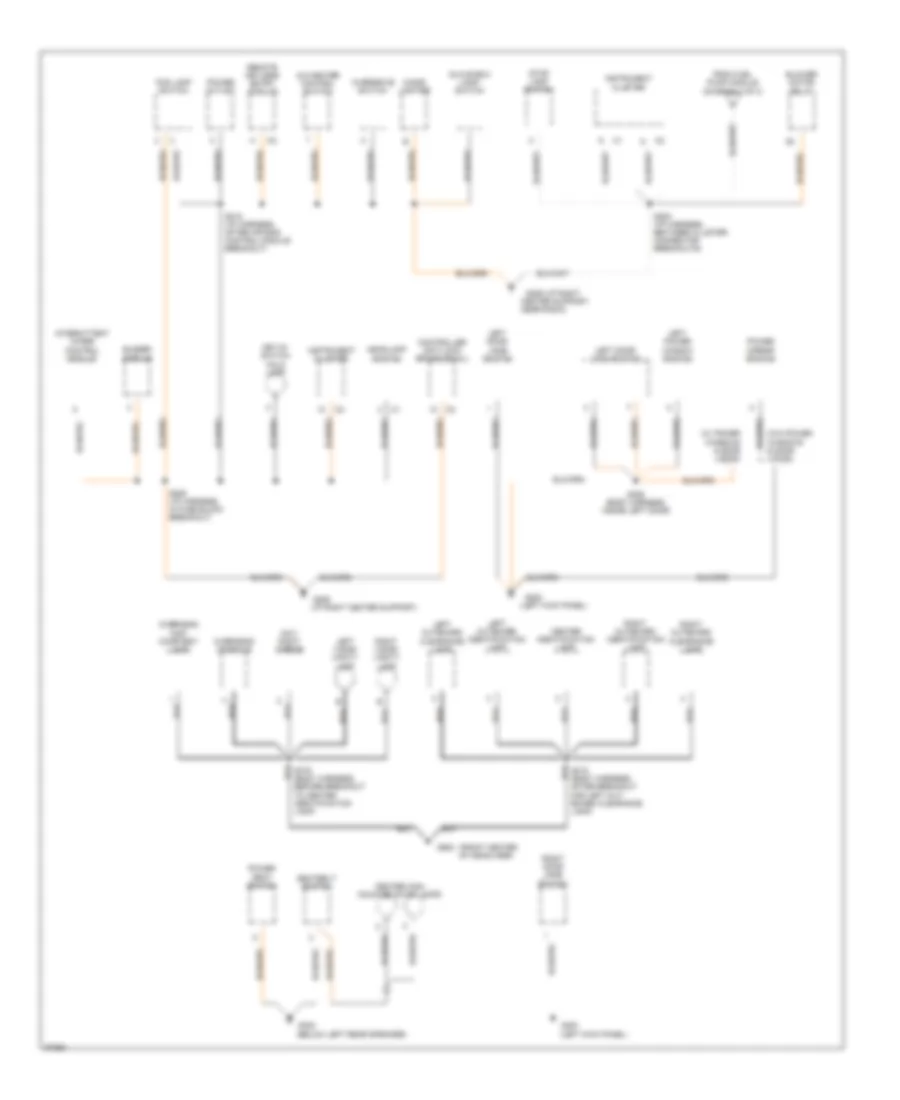 https://portal-diagnostov.com/license.html
Automotive Electricians Portal FZCO
Automotive Electricians Portal FZCO
https://portal-diagnostov.com/license.html
https://portal-diagnostov.com/license.html
Automotive Electricians Portal FZCO
Automotive Electricians Portal FZCOList of elements for Ground Distribution Wiring Diagram (3 of 3) for Dodge Pickup R1997 3500:
- (below left rear speaker)
- (front center of headliner)
- (i/p right center support)
- (left kick panel)
- (w/ power windows & door locks)
- (w/o power windows & door locks)
- A/c-heater control switch
- After breakout for left out- board clearance lamp)
- Before breakout to center identification lamp)
- Blower motor relay
- Buzzer
- Center high mounted stop lamps
- Center identification lamp
- Center support, near radio)
- Cigar lighter
- Controller anti-lock brake (rwal)
- Day/ night mirror
- Fog lamp switch
- From fuel pump module (diagram 2 of 3)
- G200
- G200
- G206
- G206 (i/p right
- G308
- G908
- Glove box lamp/ switch
- Headlamp switch
- Instrument cluster
- Intermittent wiper control module
- Key-in- switch halo lamp
- Left door jamb switch
- Left door lock switch
- Left outboard clearance lamp
- Left outboard identification lamp
- Left power window switch
- Left visor/ vanity lamp
- Module
- Overdrive switch
- Overhead console
- Overhead map/ courtesy lamp
- Power mirror switch
- Power outlet
- Power seat switch
- Remote keyless entry module
- Right door jamb switch
- Right outboard clearance lamp
- Right outboard identification lamp
- Right visor/ vanity lamp
- S206 (i/p harness, in fuse block breakout)
- S208 (i/p harness, between cluster connector breakouts)
- S215 (i/p harness, after air bag control module breakout)
- S306 (body harness, inside left door)
- Seatbelt switch
- Stop lamp switch
HEADLIGHTS
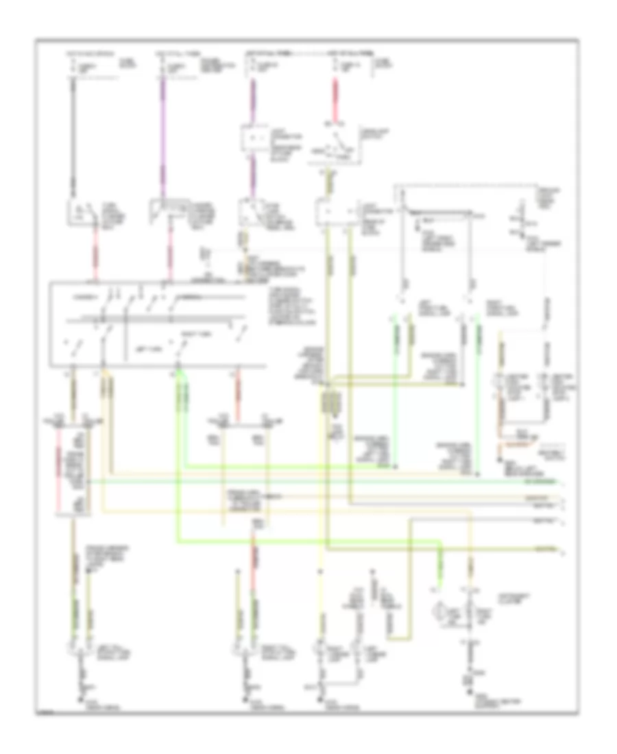
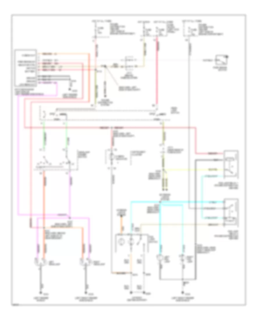
Headlamps/Fog Lamps Wiring Diagram, with DRL for Dodge Pickup R1997 3500
 https://portal-diagnostov.com/license.html
Automotive Electricians Portal FZCO
Automotive Electricians Portal FZCO
https://portal-diagnostov.com/license.html
https://portal-diagnostov.com/license.html
Automotive Electricians Portal FZCO
Automotive Electricians Portal FZCOList of elements for Headlamps/Fog Lamps Wiring Diagram, with DRL for Dodge Pickup R1997 3500:
- (eng harn, left side of eng compt)
- (i/p right center support)
- (left fender shield)
- (left fender side shield)
- (left front fender side shield)
- Battery
- Daytime running lamp module (left fender side shield)
- Exterior lights system
- Flash
- Fog lamp relay 1 (power distribution center)
- Fog lamp relay 2 (power distribution center)
- Fog lamp switch
- Fuse 10a
- Fuse 15a
- Fuse 40a
- Fuse a 15a
- Fuse block (left kick panel)
- G100
- G104
- G11
- G206
- G34
- Ground
- Head
- Head- lamp switch
- Headlamp dimmer switch
- Hi beam indicator
- Hi beam out
- Hot at all times
- Hot in run
- Ignition
- Indicator ctrl
- Instrument cluster
- Interior lights system
- J/c a (near rear of fuse block)
- J/c c (behind knee bolster)
- L10
- Left fog lamp
- Left headlamp
- Low beam out
- Off
- Park
- Park brake sw
- Park brake switch
- Pnk/red
- Power distribution center (left side of engine compartment)
- Power distribution system
- Right fog lamp
- Right headlamp
- S103 (eng harn, near right headlamp breakout)
- S104 (eng harn, near horn breakout)
- S106 (eng harn, near horn breakout)
- S107 (eng harn, left side of eng compt)
- S108
- S118
- S120
- S121 (eng harn, behind left side of i/p, near grommet)
- S153 (eng harn, left side of eng compt)
- S206
- S215
- S409
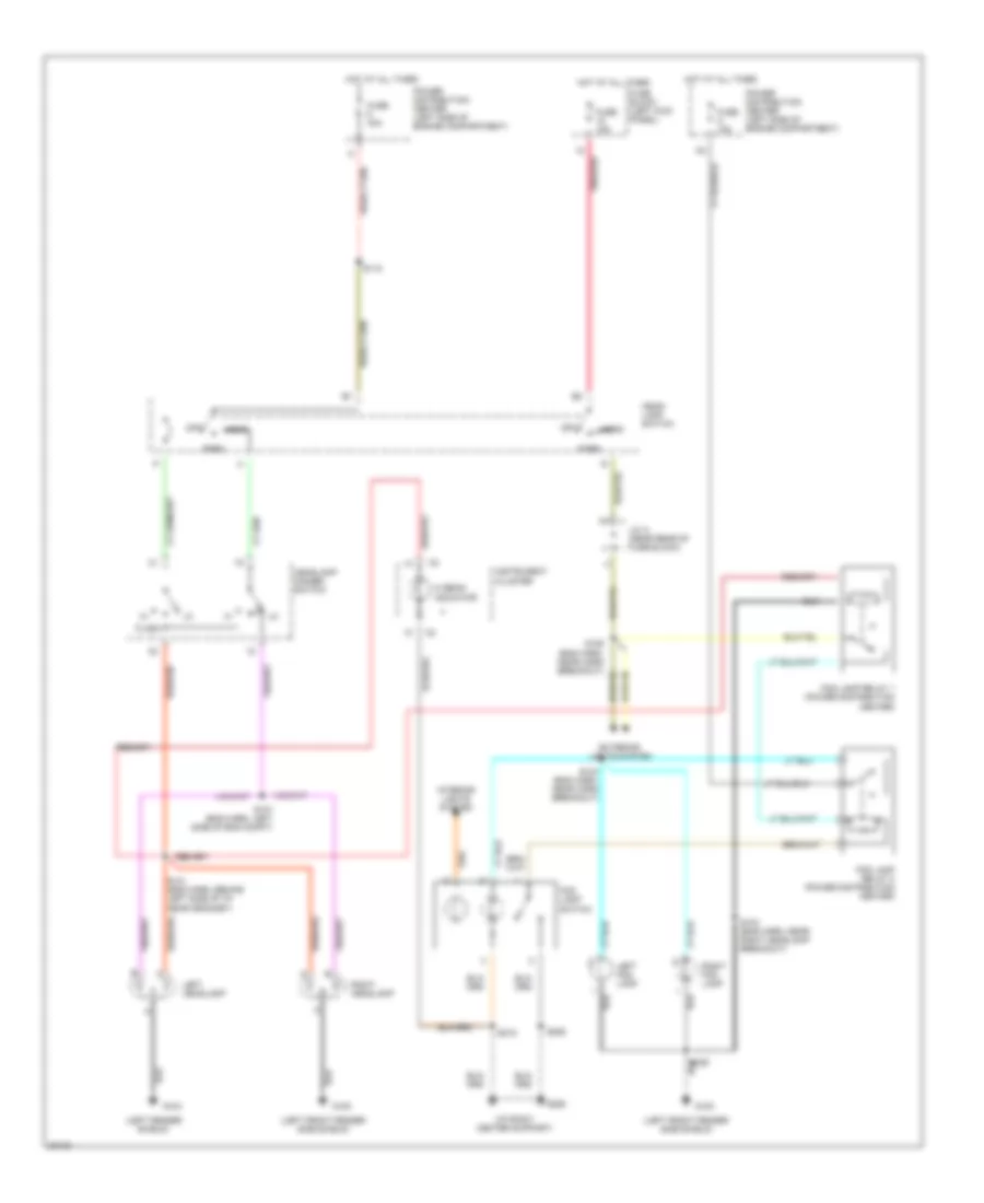
Headlamps/Fog Lamps Wiring Diagram, without DRL for Dodge Pickup R1997 3500
 https://portal-diagnostov.com/license.html
Automotive Electricians Portal FZCO
Automotive Electricians Portal FZCO
https://portal-diagnostov.com/license.html
https://portal-diagnostov.com/license.html
Automotive Electricians Portal FZCO
Automotive Electricians Portal FZCOList of elements for Headlamps/Fog Lamps Wiring Diagram, without DRL for Dodge Pickup R1997 3500:
- (i/p right center support)
- (left fender shield)
- (left front fender side shield)
- Exterior lights system
- Flash
- Fog lamp relay 1 (power distribution center)
- Fog lamp relay 2 (power distribution center)
- Fog lamp switch
- Fuse 15a
- Fuse 40a
- Fuse a 15a
- Fuse block (left kick panel)
- G100
- G104
- G206
- Head
- Head- lamp switch
- Headlamp dimmer switch
- Hi beam indicator
- Hot at all times
- Instrument cluster
- Interior lights system
- J/c a (near rear of fuse block)
- Left fog lamp
- Left headlamp
- Off
- Park
- Pnk/red
- Power distribution center (left side of engine compartment)
- Right fog lamp
- Right headlamp
- S103 (eng harn, near right headlamp breakout)
- S104 (eng harn, near horn breakout)
- S106 (eng harn, near horn breakout)
- S107 (eng harn, left side of eng compt)
- S118
- S121 (eng harn, behind left side of i/p, near grommet)
- S206
- S215
- S409
HORN
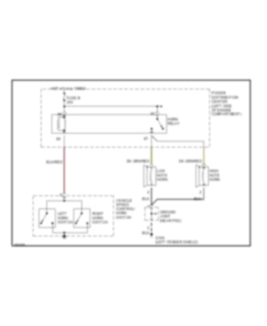
Horn Wiring Diagram for Dodge Pickup R1997 3500
 https://portal-diagnostov.com/license.html
Automotive Electricians Portal FZCO
Automotive Electricians Portal FZCO
https://portal-diagnostov.com/license.html
https://portal-diagnostov.com/license.html
Automotive Electricians Portal FZCO
Automotive Electricians Portal FZCOList of elements for Horn Wiring Diagram for Dodge Pickup R1997 3500:
- Fuse b 20a
- G104 (left fender shield)
- Ground joint (near pdc)
- High note horn
- Horn relay
- Hot at all times
- Left horn switch
- Low note horn
- Power distribution center (left side of engine compartment)
- Right horn switch
- Vehicle speed control/ horn switch
INSTRUMENT CLUSTER
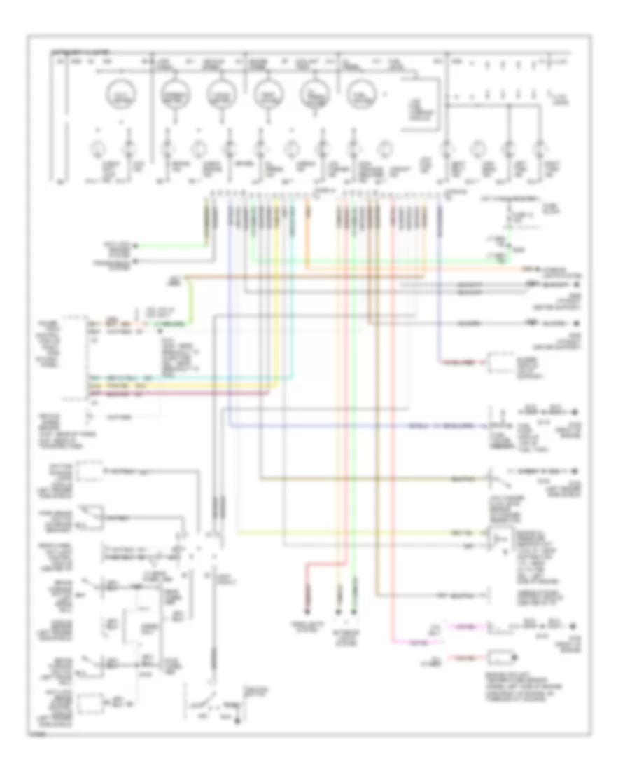
Instrument Cluster Wiring Diagram for Dodge Pickup R1997 3500
 https://portal-diagnostov.com/license.html
Automotive Electricians Portal FZCO
Automotive Electricians Portal FZCO
https://portal-diagnostov.com/license.html
https://portal-diagnostov.com/license.html
Automotive Electricians Portal FZCO
Automotive Electricians Portal FZCOList of elements for Instrument Cluster Wiring Diagram for Dodge Pickup R1997 3500:
- (2wd - rear of trans 4wd - rear of transfer case)
- (conn a)
- (conn b)
- (diesel-left side of engine)
- (gas-front of engine, on thermostat housing)
- (right
- (spare)
- (top of fuel tank)
- (v6 & v8 - near distributor
- 3.9l, 5.2l & 5.9l only
- 4wd ind.
- 8.0l only
- A10
- A11
- A13
- A14
- Acc
- Airbag ind.
- Airbag system control module (center of i/p)
- All others
- Anti-lock brake system control module (left fender side shield)
- Anti-lock brakes system
- B10
- B11
- B12
- B13
- B14
- B27
- Brake ind.
- Brake warning switch (left frame rail)
- Buzzer module (on i/p support)
- C16
- C17
- C31
- Center support)
- Check anti- lock ind.
- Check engine ind.
- Control
- Coolant temp.
- Daytime running lamps module (left fender side shield)
- Diesel only
- Dsl - left side of engine)
- Engine coolant temperature sensor
- Engine oil pressure sending unit
- Engine speed
- Exterior lights system
- Four wheel abs
- Fuel gauge
- Fuel gauge sensor
- Fuel level
- Fuel pump module
- Fuse 12 15a
- Fuse block
- G100 (left fender side shield)
- G11
- G12
- G125 (front of engine)
- G206 (i/p right
- G206 (i/p right center support)
- G21
- G54
- Gnd
- Headlights system
- High beam ind.
- Hot in run or start
- Ign
- Ignition switch
- Illum.
- Illum. lamps
- Instrument cluster
- Interior lights system
- Joint conn c
- Lamp check
- Left turn ind.
- Lock
- Low fuel ind.
- Low fuel warning module
- Low washer fluid level sensor (in washer reservoir)
- Low washer ind.
- Main- tenance required ind.
- Module
- Not used
- Of dash
- Oil press.
- Oil press. gauge
- Oil press. ind.
- Panel)
- Park brake switch (on brake bracket)
- Power-
- R41
- Rear wheel abs
- Rear wheel anti-lock control module (center i/p)
- Right turn ind.
- Run
- S108
- S109
- S116
- S131 (gas - near breakout to injectors dsl - near breakout to pcm)
- S140
- S206
- S208
- S209
- Seat belt ind.
- Side
- Speedo- meter
- Start
- Tacho- meter
- Temp. gauge
- Train
- Transmission system
- Upshift ind.
- V10 - near oil filter
- Vacuum sensor (left fender side shield)
- Vehicle speed
- Vehicle speed sensor
- Volt- meter
- W/ rear wheel abs
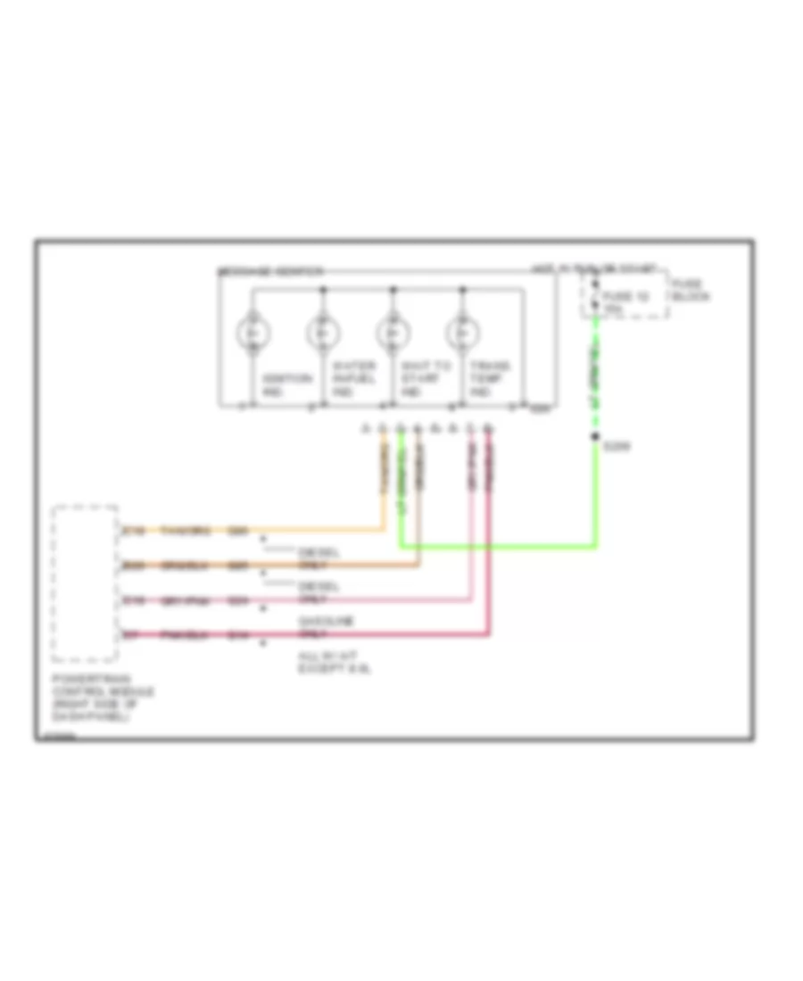
Message Center Wiring Diagram for Dodge Pickup R1997 3500
 https://portal-diagnostov.com/license.html
Automotive Electricians Portal FZCO
Automotive Electricians Portal FZCO
https://portal-diagnostov.com/license.html
https://portal-diagnostov.com/license.html
Automotive Electricians Portal FZCO
Automotive Electricians Portal FZCOList of elements for Message Center Wiring Diagram for Dodge Pickup R1997 3500:
- All w/ a/t except 8.0l
- B20
- C18
- Diesel only
- Fuse 12 15a
- Fuse block
- G14
- G24
- G85
- G86
- Gasoline only
- Hot in run or start
- Ign
- Ignition ind.
- Message center
- Powertrain control module (right side of dash panel)
- S209
- Trans. temp. ind.
- Wait to start ind.
- Water in-fuel ind.
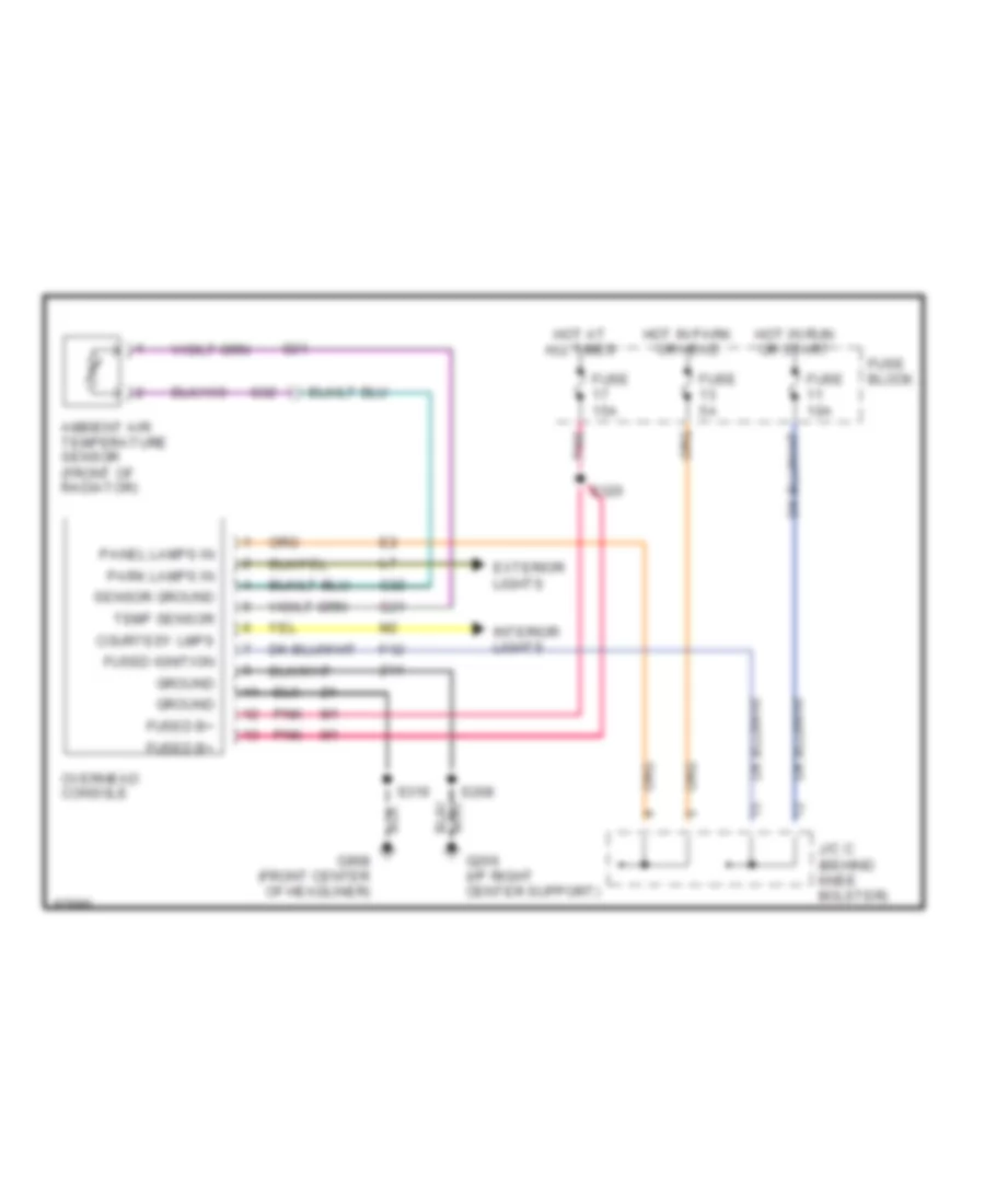
Overhead Console Wiring Diagram for Dodge Pickup R1997 3500
 https://portal-diagnostov.com/license.html
Automotive Electricians Portal FZCO
Automotive Electricians Portal FZCO
https://portal-diagnostov.com/license.html
https://portal-diagnostov.com/license.html
Automotive Electricians Portal FZCO
Automotive Electricians Portal FZCOList of elements for Overhead Console Wiring Diagram for Dodge Pickup R1997 3500:
- Ambient air temperature sensor (front of radiator)
- Courtesy lmps
- Exterior lights
- F12
- Fuse 10a
- Fuse 15a
- Fuse 5a
- Fuse block
- Fused b+
- Fused ignition
- G206 (i/p right center support)
- G31
- G32
- G908 (front center of headliner)
- Ground
- Hot at all times
- Hot in park or head
- Hot in run or start
- Interior lights
- J/c c (behind knee bolster)
- Overhead console
- Panel lamps in
- Park lamps in
- Pnk
- S208
- S319
- S320
- Sensor ground
- Temp sensor
- Z11
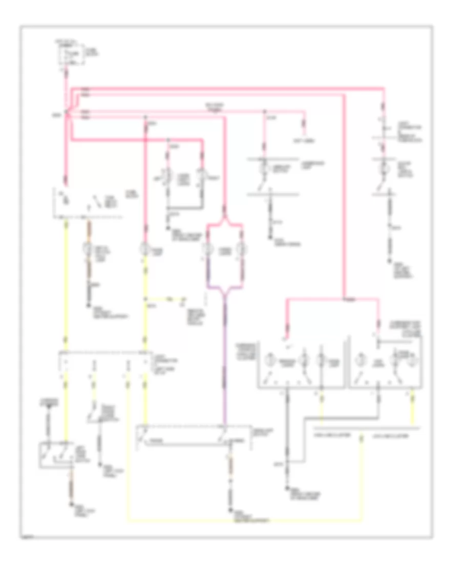
INTERIOR LIGHTS
Courtesy Lamp Wiring Diagram for Dodge Pickup R1997 3500
 https://portal-diagnostov.com/license.html
Automotive Electricians Portal FZCO
Automotive Electricians Portal FZCO
https://portal-diagnostov.com/license.html
https://portal-diagnostov.com/license.html
Automotive Electricians Portal FZCO
Automotive Electricians Portal FZCOList of elements for Courtesy Lamp Wiring Diagram for Dodge Pickup R1997 3500:
- (not used)
- B/h conn pin #34
- Cargo
- Cargo lamps
- Dome
- Dome lamp
- Fuse 15a
- Fuse block
- G100 (near horns)
- G200 (left kick panel)
- G206 (i/p left center support)
- G206 (i/p right center support)
- G908 (front center of headliner)
- Glove box lamp & switch
- Headlamp switch
- High-line cluster
- Hot at all times
- Joint connector a (left side of i/p)
- Joint connector b (rear of fuse block)
- Key-in switch halo lamp
- Left
- Left door jamb switch
- Low-line cluster
- Map lamps
- Mercury switch
- Overhead console (high-line cluster)
- Overhead map/ courtesy lamp (low-line cluster)
- Pnk
- Reading lamps
- Remote keyless entry module
- Right
- Right door jamb switch
- S115
- S149
- S205
- S215
- S218
- S303 pnk
- S319
- S320
- Time delay relay
- Underhood lamp
- Visor/ vanity lamps
- Warning systems
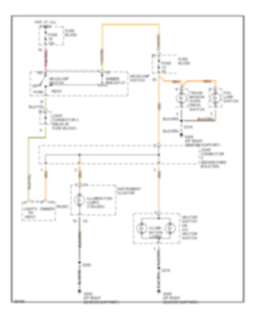
Instrument Illumination Wiring Diagram for Dodge Pickup R1997 3500
 https://portal-diagnostov.com/license.html
Automotive Electricians Portal FZCO
Automotive Electricians Portal FZCO
https://portal-diagnostov.com/license.html
https://portal-diagnostov.com/license.html
Automotive Electricians Portal FZCO
Automotive Electricians Portal FZCOList of elements for Instrument Illumination Wiring Diagram for Dodge Pickup R1997 3500:
- Dimmer
- Dimmer rheostat
- Fog lamp switch
- Fuse 15a
- Fuse 5a
- Fuse block
- G206 (i/p right center support)
- Head
- Headlamp switch
- Heater switch or a/c heater switch
- Hot at all times
- Illumi-
- Illumination lamps (7 bulbs)
- Instrument cluster
- Joint connector a (rear of fuse block)
- Joint connector c (behind knee bolster)
- Lights on input
- Nation lamps
- Off
- Park
- Pnk/red
- Radio
- S206
- S215
- Trans- mission over- drive switch
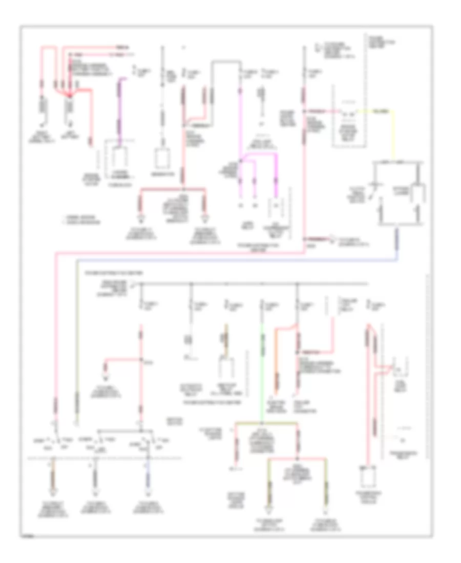
POWER DISTRIBUTION
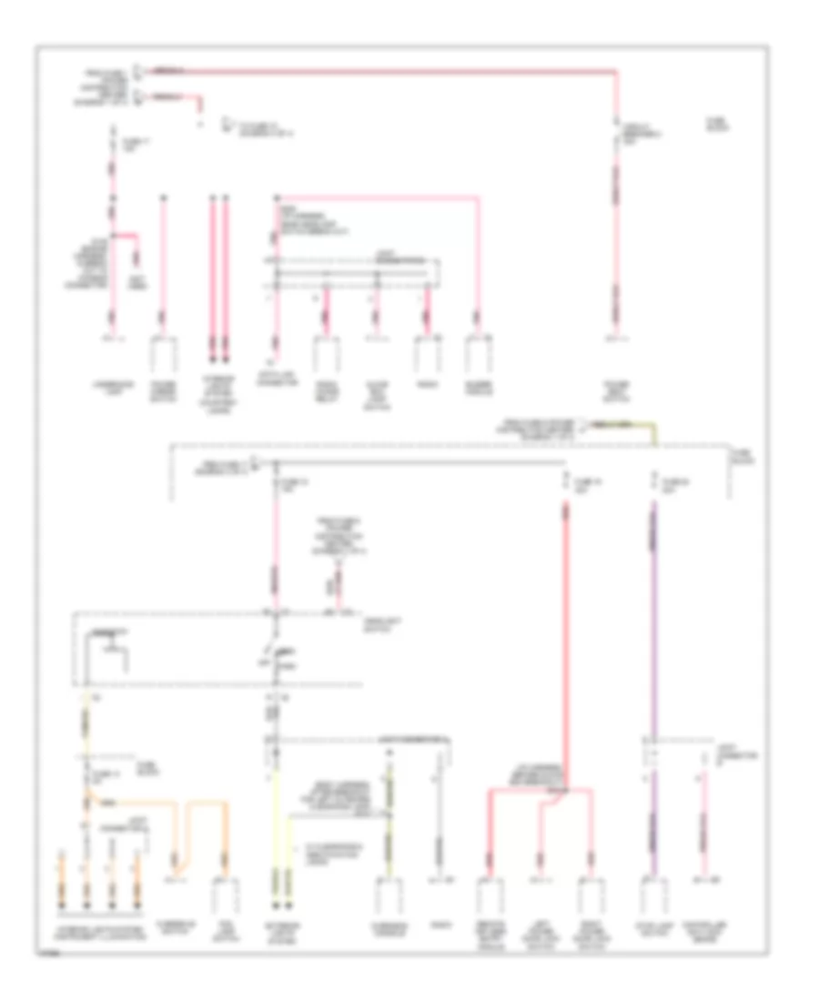
Power Distribution Wiring Diagram (1 of 4) for Dodge Pickup R1997 3500
 https://portal-diagnostov.com/license.html
Automotive Electricians Portal FZCO
Automotive Electricians Portal FZCO
https://portal-diagnostov.com/license.html
https://portal-diagnostov.com/license.html
Automotive Electricians Portal FZCO
Automotive Electricians Portal FZCOList of elements for Power Distribution Wiring Diagram (1 of 4) for Dodge Pickup R1997 3500:
- 40a
- 50a
- A/c compressor clutch relay
- A/t
- A22
- Abs pump relay (all wheel abs)
- Acc
- Automatic shutdown relay
- Bypass jumper
- Center (diagram 1 of 4)
- Clutch pedal position switch
- Daytime running lamps module
- Diesel engine
- Electric brake provision
- Engine starter motor
- Engine starter motor relay
- Fog lamp relay no. 2
- From power distribution a
- Fuel pump relay
- Fuse 1
- Fuse 2
- Fuse 3 40a
- Fuse 4 30a
- Fuse 5 40a
- Fuse 6 40a
- Fuse 7 30a
- Fuse 8 20a
- Fuse a 15a
- Fuse b 20a
- Fuse block
- Fuse c 20a
- Gasoline engine
- Gen fuse 120a
- Generator
- Hazard flasher
- Horn relay
- Ignition switch
- Left battery
- M/t
- Off
- Pnk
- Power distri- bution center
- Power distribution center
- Powertrain control module
- Red
- Red/
- Red/tan
- Right battery (diesel only)
- Run
- S118 (drl only) (i/p harness, in breakout to chassis connector)
- S119 (engine harness, in breakout to chassis connector)
- S124
- S146 (engine harness, in pdc)
- S147 (engine harness, in pdc)
- S148 (engine harness, battery positive harness assembly)
- S155 (engine harness, in pdc)
- S203 (i/p harness, in headlamp switch break out)
- S204 (w/ power seats only) (i/p harness, in headlamp switch breakout)
- S220
- Start
- To circuit breaker 1 (fuse block) (diagram 4 of 4)
- To circuit breaker 2 (fuse block) (diagram 3 of 4)
- To fuse 1 (fuse block) (diagram 2 of 4)
- To fuse 17 (fuse block) (diagram 3 of 4)
- To fuse 20 (fuse block) (diagram 3 of 4)
- To fuse 5 (fuse block) (diagram 2 of 4)
- To fuse 9 (fuse block) (diagram 2 of 4)
- To fuse f2 (diagram 2 of 4)
- To headlamp switch (diagram 3 of 4)
- To power distribution center (diagram 1 of 4)
- Trailer tow connector
- Trailer tow relay
- Transmission relay
- W/ daytime running lights
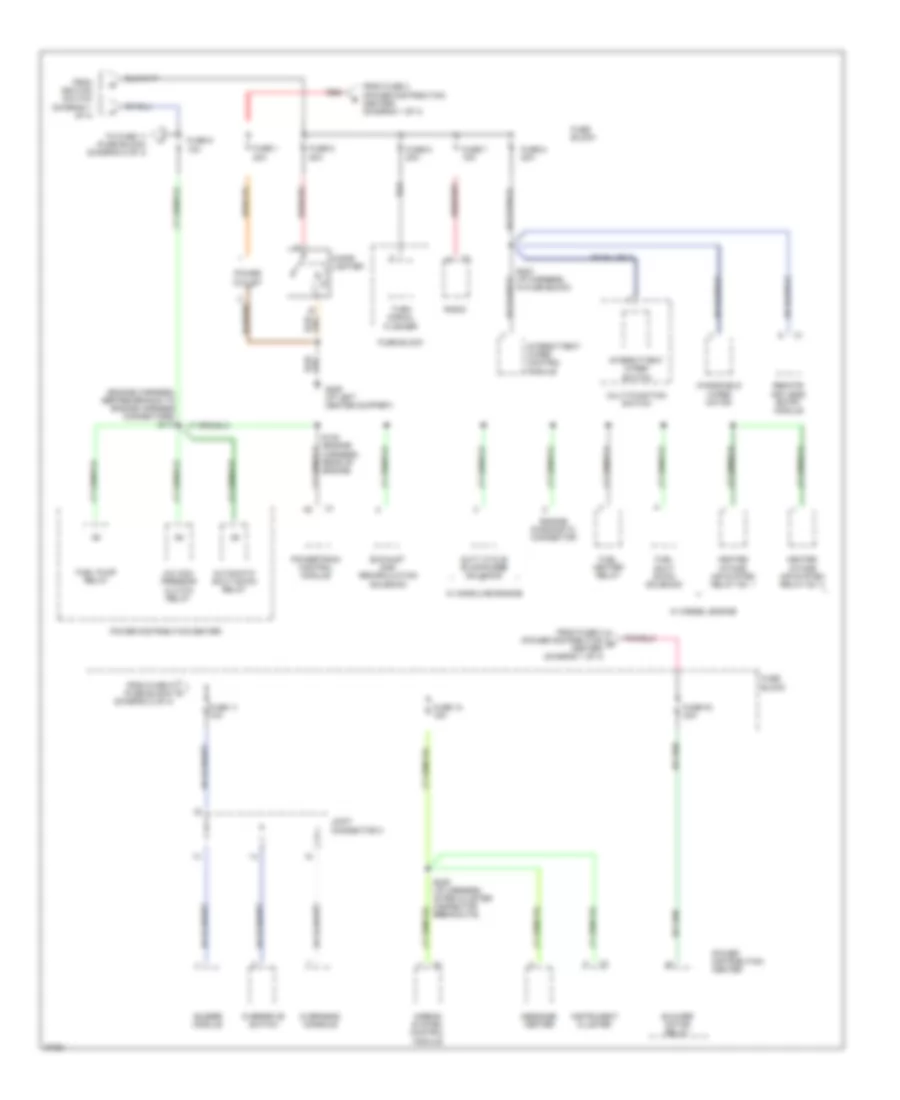
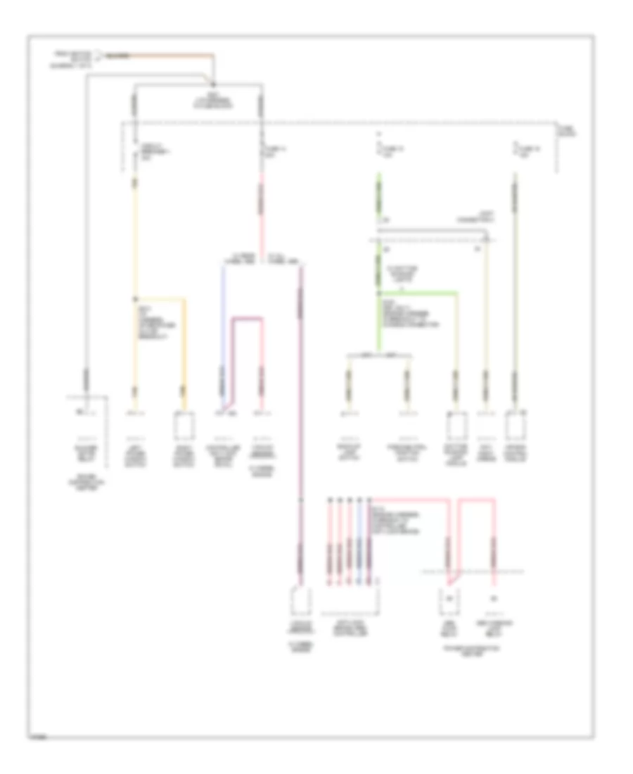
Power Distribution Wiring Diagram (2 of 4) for Dodge Pickup R1997 3500
 https://portal-diagnostov.com/license.html
Automotive Electricians Portal FZCO
Automotive Electricians Portal FZCO
https://portal-diagnostov.com/license.html
https://portal-diagnostov.com/license.html
Automotive Electricians Portal FZCO
Automotive Electricians Portal FZCOList of elements for Power Distribution Wiring Diagram (2 of 4) for Dodge Pickup R1997 3500:
- (diagram 2 of 4)
- (engine harness, before branch to engine harness connectors) s114
- A/c com- pressor clutch relay
- Airbag system control module
- Automatic shut down relay
- Blower motor relay
- Buzzer module
- Cigar lighter
- Duty cycle evap/purge solenoid
- Engine diagnostic connector
- Exhaust gas recirculation solenoid
- From fuse 2 (power distribution d center) (diagram 1 of 4)
- From fuse 3 (power distribution center) (diagram 1 of 4)
- From fuse 9 (fuse block) l
- From ignition switch (diagram 1 of 4)
- Fuel heater relay
- Fuel pump relay
- Fuel shut down solenoid
- Fuse 1 20a
- Fuse 11 10a
- Fuse 12 15a
- Fuse 5 20a
- Fuse 6 20a
- Fuse 7 15a
- Fuse 8 20a
- Fuse 9 10a
- Fuse block
- Fuse f2 30a
- G206 (i/p left center support)
- Heated intake air system relay no. 1
- Heated intake air system relay no. 2
- Instrument cluster
- Intermittent wiper control module
- Intermittent wiper switch
- Joint connector c
- Message center
- Multi-function switch
- Overdrive switch
- Overhead console
- Power distribution center
- Power outlet
- Powertrain control module
- Radio
- Red
- Remote keyless entry module
- S132 (engine harness, rear of engine)
- S202 (i/p harness, in fuse block)
- S209 (i/p harness, after cluster connector breakouts)
- To fuse 11 (fuse block) (diagram 2 of 4)
- Turn signal flasher
- W/ diesel engine
- W/ gasoline engine
- Windshield wiper motor
Power Distribution Wiring Diagram (3 of 4) for Dodge Pickup R1997 3500
 https://portal-diagnostov.com/license.html
Automotive Electricians Portal FZCO
Automotive Electricians Portal FZCO
https://portal-diagnostov.com/license.html
https://portal-diagnostov.com/license.html
Automotive Electricians Portal FZCO
Automotive Electricians Portal FZCOList of elements for Power Distribution Wiring Diagram (3 of 4) for Dodge Pickup R1997 3500:
- (body harness, after breakout for left outboard clearance lamp) s317
- (courtesy lamps)
- (i/p harness, before glove box breakout) s216
- (not used)
- Buzzer module
- Circuit breaker 2 30a
- Controller anti-lock brake
- Data link connector
- Exterior lights
- Fog lamp switch
- From fuse 1 (power distribution center) (diagram 1 of 4)
- From fuse 17 m (diagram 3 of 4)
- From fuse 6 (power distribution center) (diagram 1 of 4)
- Fuse 13 5a
- Fuse 17 15a
- Fuse 18 15a
- Fuse 19 20a
- Fuse 20 20a
- Fuse block
- Glove box lamp/ switch
- Head
- Headlight switch
- Interior lights system
- Interior lights system (instrument illumination)
- Joint connector a
- Joint connector b
- Joint connector c
- Left power door lock switch
- Off
- Overdrive switch
- Overhead console
- Park
- Pnk
- Pnk/red
- Power mirror switch
- Power seat switch
- Radio
- Radio choke relay
- Red
- Remote keyless entry module
- Rheostat
- Right power door lock switch
- S149 (engine harness, in break out to chassis connector)
- S205 (i/p harness, near headlamp switch break out)
- Stop lamp switch
- System
- To fuse 18 (diagram 3 of 4)
- Underhood lamp
- W/ clearance & identification lamps
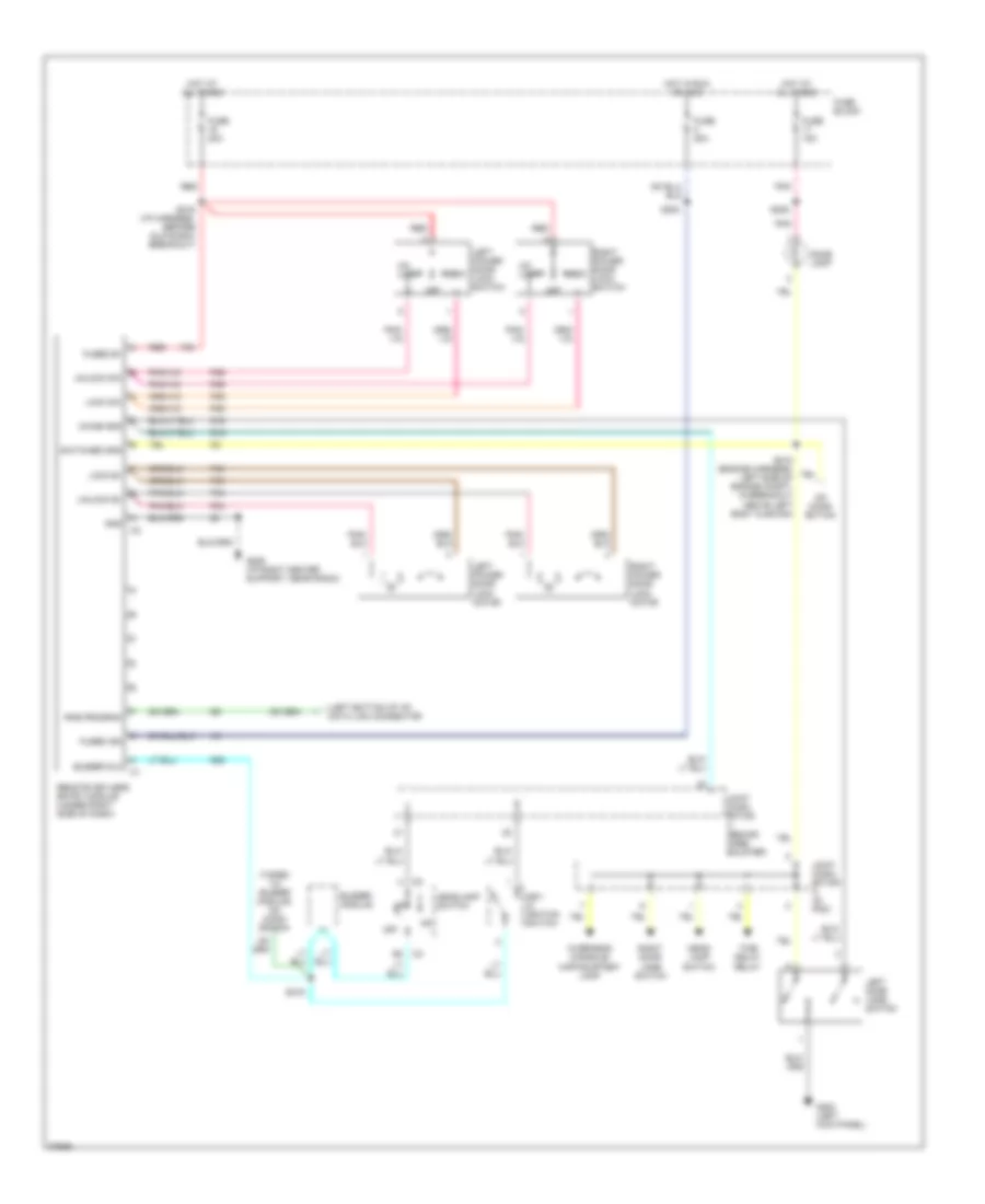
Power Distribution Wiring Diagram (4 of 4) for Dodge Pickup R1997 3500
 https://portal-diagnostov.com/license.html
Automotive Electricians Portal FZCO
Automotive Electricians Portal FZCO
https://portal-diagnostov.com/license.html
https://portal-diagnostov.com/license.html
Automotive Electricians Portal FZCO
Automotive Electricians Portal FZCOList of elements for Power Distribution Wiring Diagram (4 of 4) for Dodge Pickup R1997 3500:
- A/t
- Abs pump relay
- Abs warning lamp relay
- Air bag control module
- Anti-lock brake (abs) controller
- Back-up lamp switch
- Blower motor relay
- Circuit breaker 1 30a
- Controller anti-lock brake (rwal)
- Day/ night mirror
- Daytime running lamp module
- From ignition switch (diagram 1 of 4)
- Fuse 14 20a
- Fuse 15 10a
- Fuse 16 15a
- Fuse block
- Joint connector c
- Left power window switch
- M/t
- Park/neutral position switch
- Power distribution center
- Right power window switch
- S110 (engine harness, in branch to controller anti-lock brake)
- S120 (drl only) (engine harness, in breakout to chassis connector)
- S201 (i/p harness, in fuse block)
- S214 (i/p harness, after power outlet breakout)
- Tan
- Vacuum sensor
- W/ all wheel abs
- W/ daytime running lights
- W/ diesel engine
- W/ rear wheel abs
POWER DOOR LOCKS
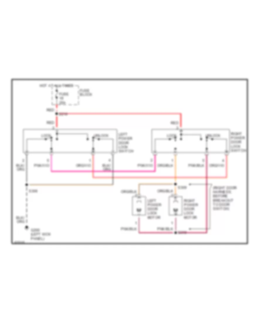
Door Lock Wiring Diagram for Dodge Pickup R1997 3500
 https://portal-diagnostov.com/license.html
Automotive Electricians Portal FZCO
Automotive Electricians Portal FZCO
https://portal-diagnostov.com/license.html
https://portal-diagnostov.com/license.html
Automotive Electricians Portal FZCO
Automotive Electricians Portal FZCOList of elements for Door Lock Wiring Diagram for Dodge Pickup R1997 3500:
- (right door harness, before breakout to door switch)
- Fuse 20a
- Fuse block
- G200 (left kick panel)
- Hot at all times
- Left power door lock motor
- Left power door lock switch
- Lock
- Red
- Right power door lock motor
- Right power door lock switch
- S216
- S306
- S309
- S310
- Unlock
Keyless Entry Wiring Diagram for Dodge Pickup R1997 3500
 https://portal-diagnostov.com/license.html
Automotive Electricians Portal FZCO
Automotive Electricians Portal FZCO
https://portal-diagnostov.com/license.html
https://portal-diagnostov.com/license.html
Automotive Electricians Portal FZCO
Automotive Electricians Portal FZCOList of elements for Keyless Entry Wiring Diagram for Dodge Pickup R1997 3500:
- (left bottom of i/p) data link connector
- (taped to buzzer module) no conn- ection
- Buzzer dlc
- Buzzer module
- Chime gnd
- Dome lamp
- F35
- Fuse 15a
- Fuse 20a
- Fuse block
- Fused b+
- Fused ign
- G16
- G200 (left kick panel)
- G206 (i/p right center support, near radio)
- G26
- Gnd
- Head- lamp switch
- Headlamp switch
- Hot at all times
- Hot in run or acc
- Joint conn- ector a (in pdc)
- Joint conn- ector c (behind knee bolster)
- Key- in ignition switch
- Left door jamb switch
- Left power door lock lock switch
- Left power door lock motor
- Lock b+
- Lock sw
- No conn- ection
- Off
- Overhead console/ map/courtesy lamp
- P33
- P34
- P35
- P36
- Pnk
- Red
- Remote keyless entry module (under right side of dash)
- Right door jamb switch
- Right power door lock lock switch
- Right power door lock motor
- Rke program
- S202
- S205
- S216 (i/p harness, before glove box breakout)
- S218 (engine harness, left side of engine compt, in breakout above left body cushion)
- S219
- Switched gnd
- Time delay relay
- Un- lock
- Unlock b+
- Unlock sw
POWER MIRRORS
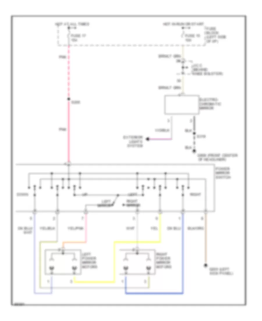
Power Mirror Wiring Diagram for Dodge Pickup R1997 3500
 https://portal-diagnostov.com/license.html
Automotive Electricians Portal FZCO
Automotive Electricians Portal FZCO
https://portal-diagnostov.com/license.html
https://portal-diagnostov.com/license.html
Automotive Electricians Portal FZCO
Automotive Electricians Portal FZCOList of elements for Power Mirror Wiring Diagram for Dodge Pickup R1997 3500:
- (front center
- (left
- Down
- Electro- chromatic mirror
- Exterior lights system
- Fuse 15 10a
- Fuse 17 15a
- Fuse block (left side of i/p)
- G200 kick panel)
- G908 of headliner)
- Hot at all times
- Hot in run or start
- J/c c (behind knee bolster)
- Left
- Left mirror
- Left power mirror motors
- Pnk
- Power mirror switch
- Right
- Right mirror
- Right power mirror motors
- S205
- S319
POWER SEATS
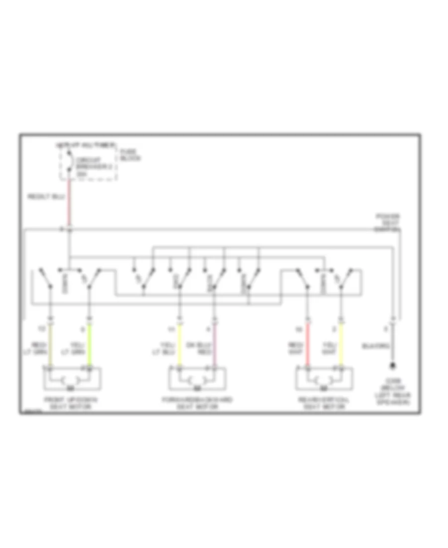
Power Seat Wiring Diagrams for Dodge Pickup R1997 3500
 https://portal-diagnostov.com/license.html
Automotive Electricians Portal FZCO
Automotive Electricians Portal FZCO
https://portal-diagnostov.com/license.html
https://portal-diagnostov.com/license.html
Automotive Electricians Portal FZCO
Automotive Electricians Portal FZCOList of elements for Power Seat Wiring Diagrams for Dodge Pickup R1997 3500:
- Back
- Circuit breaker 2 30a
- Down
- Forward/backward seat motor
- Front up/down seat motor
- Fuse block
- Fwd
- G308 (below left rear speaker)
- Hot at all times
- Power seat switch
- Rear/vertical seat motor
POWER WINDOWS
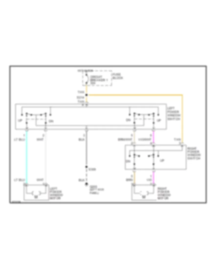
Power Window Wiring Diagram for Dodge Pickup R1997 3500
 https://portal-diagnostov.com/license.html
Automotive Electricians Portal FZCO
Automotive Electricians Portal FZCO
https://portal-diagnostov.com/license.html
https://portal-diagnostov.com/license.html
Automotive Electricians Portal FZCO
Automotive Electricians Portal FZCOList of elements for Power Window Wiring Diagram for Dodge Pickup R1997 3500:
- Circuit breaker 1 30a
- Fuse block
- G200 (left kick panel)
- Hot in run
- Left power window motor
- Left power window switch
- Right power window motor
- Right power window switch
- S214
- S306
- Tan
RADIO
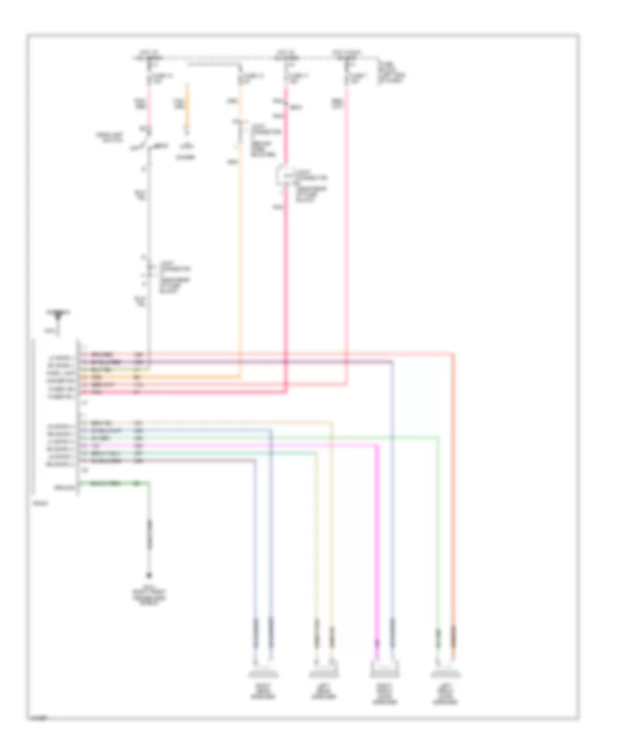
Radio Wiring Diagrams, Base Radio for Dodge Pickup R1997 3500
 https://portal-diagnostov.com/license.html
Automotive Electricians Portal FZCO
Automotive Electricians Portal FZCO
https://portal-diagnostov.com/license.html
https://portal-diagnostov.com/license.html
Automotive Electricians Portal FZCO
Automotive Electricians Portal FZCOList of elements for Radio Wiring Diagrams, Base Radio for Dodge Pickup R1997 3500:
- Antenna
- Dimmer
- Dimmer sig
- Fender side shield)
- Fuse 13 5a
- Fuse 17 15a
- Fuse 18 15a
- Fuse 7 15a
- Fuse block (left end of dash)
- Fused b(+)
- Fused ign
- G101 (right front
- Ground
- Head
- Headlamp switch
- Hot at all times
- Hot in run or acc
- Joint connector a (near rear of fuse block)
- Joint connector b (near rear of fuse block)
- Joint connector c (behind knee bolster)
- Left front door speaker
- Left rear speaker
- Lf spkr (+)
- Lf spkr (-)
- Lr spkr (+)
- Lr spkr (-)
- Nca
- Off
- Park lamp
- Pnk
- Pnk/ red
- Radio
- Rf spkr (+)
- Rf spkr (-)
- Right front door speaker
- Right rear speaker
- Rr spkr (+)
- Rr spkr (-)
- S205
- X12
- X51
- X52
- X53
- X54
- X55
- X56
- X57
- X58
Radio Wiring Diagrams, Premium Radio for Dodge Pickup R1997 3500
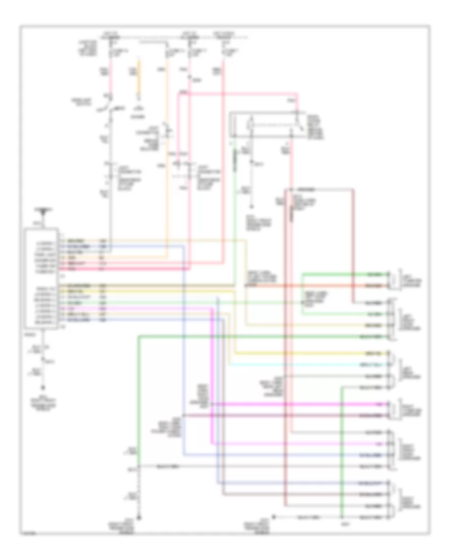 https://portal-diagnostov.com/license.html
Automotive Electricians Portal FZCO
Automotive Electricians Portal FZCO
https://portal-diagnostov.com/license.html
https://portal-diagnostov.com/license.html
Automotive Electricians Portal FZCO
Automotive Electricians Portal FZCOList of elements for Radio Wiring Diagrams, Premium Radio for Dodge Pickup R1997 3500:
- (body harn, in left power mirror motor) s305
- (body harn, left door speaker) s304
- (body harn, right door speaker) s307
- Antenna
- Dimmer
- Dimmer sig
- Fender side shield)
- Fuse 13 5a
- Fuse 17 15a
- Fuse 18 15a
- Fuse 7 15a
- Fused b(+)
- Fused ign
- G101 (right front
- G101 (right front fender side shield)
- Head
- Headlamp switch
- Hot at all times
- Hot in run or acc
- Joint connector a (near rear of fuse block)
- Joint connector b (near rear of fuse block)
- Joint connector c (behind knee bolster)
- Junction block (left end of dash)
- Left front door speaker
- Left rear speaker
- Left tweeter speaker
- Lf spkr (+)
- Lf spkr (-)
- Lr spkr (+)
- Lr spkr (-)
- Nca
- Off
- Park lamp
- Pnk
- Pnk/ red
- Radio
- Radio 12v
- Radio choke relay (behind center of dash)
- Right front door speaker
- Right rear speaker
- Right tweeter speaker
- Rr spkr (+)
- Rr spkr (-)
- S205
- S212
- S213 (dash harn, center of dash)
- S301
- S302 (body harn, near left rear speaker)
- S308 (body harn, right door power window motor)
- X12
- X51
- X52
- X53
- X54
- X55
- X56
- X57
- X58
- X60
STARTING/CHARGING
Charging Wiring Diagram for Dodge Pickup R1997 3500
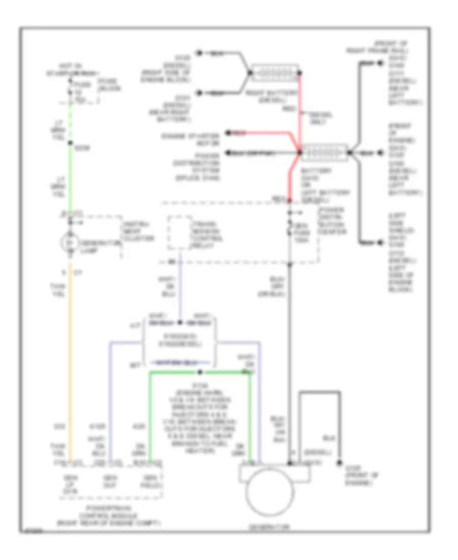 https://portal-diagnostov.com/license.html
Automotive Electricians Portal FZCO
Automotive Electricians Portal FZCO
https://portal-diagnostov.com/license.html
https://portal-diagnostov.com/license.html
Automotive Electricians Portal FZCO
Automotive Electricians Portal FZCOList of elements for Charging Wiring Diagram for Dodge Pickup R1997 3500:
- (diesel)
- (front of engine) (gas) g125
- (front of right frame rail)
- (gas)
- (gas) g100
- (left side shield) (gas) g100
- A/t
- B10
- Battery (gas) or left battery (diesel)
- C16
- C25
- Diesel only
- Engine starter motor
- Fuse 15a
- Fuse block
- G100 (diesel) (near left battery)
- G101 (diesel) (near right battery)
- G111 (diesel) (near left battery)
- G112 (diesel) (left side of engine block)
- G12
- G120 (diesel) (right side of engine block)
- G125 (front of engine)
- Gen field
- Gen fuse 120a
- Gen lp dvr
- Gen out
- Generator
- Generator lamp
- Hot in start or run
- Instru- ment cluster
- K125
- K20
- M/t
- Power distri- bution center
- Power distribution system (splice s148)
- Powertrain control module (right rear of engine compt)
- Red
- Right battery (diesel)
- S134 (engine harn, v6 & v8: between breakouts for injectors 4 & 6; v10: between break- outs for injectors 6 & 8; diesel: near branch to fuel heater)
- S163(gas) s162(diesel)
- S209
- Trans- mission control relay
Starting Wiring Diagram for Dodge Pickup R1997 3500
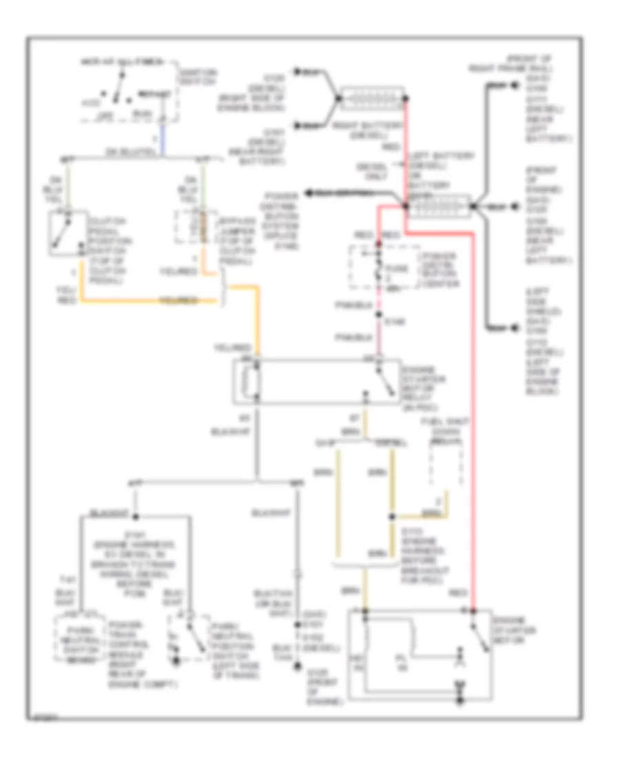 https://portal-diagnostov.com/license.html
Automotive Electricians Portal FZCO
Automotive Electricians Portal FZCO
https://portal-diagnostov.com/license.html
https://portal-diagnostov.com/license.html
Automotive Electricians Portal FZCO
Automotive Electricians Portal FZCOList of elements for Starting Wiring Diagram for Dodge Pickup R1997 3500:
- (front of engine) (gas) g125
- (front of right frame rail)
- (gas) g100
- (left side shield) (gas) g100
- A/t
- Acc
- Bypass jumper (top of clutch pedal)
- Clutch pedal position switch (top of clutch pedal)
- Diesel
- Diesel only
- Engine starter motor
- Engine starter motor relay (in pdc)
- Fuel shut down relay
- Fuse 40a
- G100 (diesel) (near left battery)
- G101 (diesel) (near right battery)
- G111 (diesel) (near left battery)
- G112 (diesel) (left side of engine block)
- G120 (diesel) (right side of engine block)
- G125 (front of engine)
- Gas
- Hd in
- Hot at all times
- Ignition switch
- Left battery (diesel) or battery (gas)
- M/t
- Off
- P/ n
- Park/ neutral position switch (left side of trans)
- Park/ neutral switch sense
- Pl in
- Power distri- bution center
- Power distrib- bution system (splice s148)
- Power- train control module (right rear of engine compt)
- Red
- Right battery (diesel)
- Run
- S113 (engine harness, before breakout for pdc)
- S141 (engine harness, ex diesel: in branch to trans wiring; diesel: before pcm)
- S146
- Start
- T41
SUPPLEMENTAL RESTRAINTS
Supplemental Restraint Wiring Diagram for Dodge Pickup R1997 3500
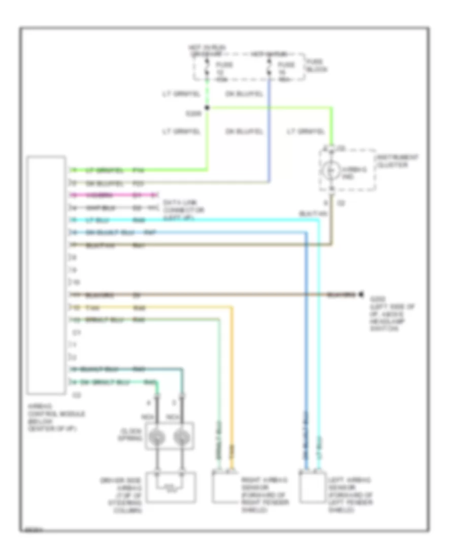 https://portal-diagnostov.com/license.html
Automotive Electricians Portal FZCO
Automotive Electricians Portal FZCO
https://portal-diagnostov.com/license.html
https://portal-diagnostov.com/license.html
Automotive Electricians Portal FZCO
Automotive Electricians Portal FZCOList of elements for Supplemental Restraint Wiring Diagram for Dodge Pickup R1997 3500:
- Airbag control module (below center of i/p)
- Airbag ind.
- Clock spring
- Data link connector (left i/p)
- Driver side airbag (top of steering column)
- F14
- F23
- Fuse 15a
- Fuse block
- G202 (left side of i/p, above headlamp switch)
- Hot in run
- Hot in run or start
- Instrument cluster
- Left airbag sensor (forward of left fender shield)
- Nca
- R41
- R43
- R45
- R46
- R47
- R48
- R49
- Right airbag sensor (forward of right fender shield)
- S209
- Tan
TRANSMISSION
3.9L
3.9L, Transmission Wiring Diagram (1 of 2) for Dodge Pickup R1997 3500
 https://portal-diagnostov.com/license.html
Automotive Electricians Portal FZCO
Automotive Electricians Portal FZCO
https://portal-diagnostov.com/license.html
https://portal-diagnostov.com/license.html
Automotive Electricians Portal FZCO
Automotive Electricians Portal FZCOList of elements for 3.9L, Transmission Wiring Diagram (1 of 2) for Dodge Pickup R1997 3500:
- (eng harn, in branch to controller anti-lock brakes)
- (front of engine) g125
- (i/p right center support, near radio) g206
- (left bottom of dash)
- (left fender side shield) g100
- 4wd ind
- 4wd sense
- 4wd switch (on front axle tube)
- A/c compressor relay, fuel pump relay
- A14
- A16
- A17
- A22
- A23
- A31
- A32
- Abs
- Air bag system control module & message center
- B11
- B21
- B25
- B27
- B28
- B29
- B30
- B31
- Brake sw sense
- C13
- C17
- C24
- C25
- C27
- C29
- Connector
- Controller anti-lock brake (abs)
- Controller anti-lock brake (behind (center of dash)
- D20
- D21
- Data link connector (partial)
- Ect sens sig
- Engine controls system
- Engine diagnostic
- F18
- Fog lamp switch
- Fuse 10a
- Fuse 15a
- Fuse 5a
- Fuse block
- Fused b(+)
- Fused ign (st/run)
- G107
- G206 (i/p right center support, near radio)
- Generator output
- Gnd
- Gov press sig
- Hot at all times
- Hot in run or start
- Hot w/headlamp switch in park or head position (rheostat controlled)
- If equipped
- Illum
- Ind
- Instrument cluster
- Joint connector c (behind knee bolster)
- Joint connector c (pin 5) (interior light system)
- K125
- K22
- K30
- K54
- K88
- Mil driversense
- Mil ind
- Od lamp driver
- Od sol ctrl
- Ou shft spd sig
- Out shaft spd gnd
- Overdrive switch
- Pnk
- Pnp sw sense
- Powertrain control module (in eng compt, on right side of dash panel)
- Rwal
- S103
- S105 (eng harn, in branch for horn breakout)
- S111
- S114
- S132
- S139
- S208
- S209
- S215
- Sc1 receive
- Sci transmit
- Sensor gnd
- Stop lamp switch (top of brake pedal bracket)
- T13
- T14
- T18
- T25
- T41
- T54
- T60
- Tcc sol ctrl
- Tp sens sig
- Trans od sw sense
- Trans rly ctrl
- Trans temp sens
- Transmission output shaft speed sensor (on left side of transmission)
- V40
- Var sol ctrl
- Vss signal
- Z12
3.9L, Transmission Wiring Diagram (2 of 2) for Dodge Pickup R1997 3500
 https://portal-diagnostov.com/license.html
Automotive Electricians Portal FZCO
Automotive Electricians Portal FZCO
https://portal-diagnostov.com/license.html
https://portal-diagnostov.com/license.html
Automotive Electricians Portal FZCO
Automotive Electricians Portal FZCOList of elements for 3.9L, Transmission Wiring Diagram (2 of 2) for Dodge Pickup R1997 3500:
- (after branch to fuel injectors 2,4,6,8 & (10)) (3.9l, 5.2l, 5.2l cng, 5.9l & 8.0l engines) s131
- (eng harn, near branch to fuel inj 2,4,6,8 or 10) s129
- (eng harn, near branch to fuel injectors 2,4,6,8 or 10)
- Engine controls system
- Engine coolant temperature sensor (between generator & a/c compressor)
- Engine starter motor relay
- Fuel pump relay
- Fuse 20a
- Generator
- Governor pressure signal
- Hot at all times
- Instrument cluster (speedometer)
- Overdrive solenoid control
- Park/ neutral position switch (on left side of transmission)
- Pnk
- Power distribution center
- Power distribution center
- Red
- S130
- S136 (eng harn, 3.9l, 5.2l & 5.9l: near crankshaft position sensor breakout, 8.0l: between fuel inj 5 & 7 breakout)
- S137 (eng harn, 3.9l, 5.2l, & 5.9l: near distributor breakout; 8.0l: near breakout to idle air control motor)
- S141 (eng harn, 3.9l 5.2l & 5.9l: in branch to trans wiring harn; 8.0l: before branch to oxygen & vehicle speed sensor)
- S154 (eng harn, before branch to fuel inj 1,3,5,7 or 9)
- S163
- Sensor ground
- Throttle position sensor (on throttle body)
- Torque converter clutch solenoid control
- Trans ctrl rly output
- Transmission control relay
- Transmission solenoid assembly (transmission)
- Transmission temperature sensor signal
- Variable force solenoid control
- Vehicle speed sensor (2wd: on left side of transmission extension housing, 4wd: on left side of transfer case)
5.2L
5.2L, Transmission Wiring Diagram (1 of 2) for Dodge Pickup R1997 3500
 https://portal-diagnostov.com/license.html
Automotive Electricians Portal FZCO
Automotive Electricians Portal FZCO
https://portal-diagnostov.com/license.html
https://portal-diagnostov.com/license.html
Automotive Electricians Portal FZCO
Automotive Electricians Portal FZCOList of elements for 5.2L, Transmission Wiring Diagram (1 of 2) for Dodge Pickup R1997 3500:
- (eng harn, in branch to controller anti-lock brakes)
- (front of engine) g125
- (i/p right center support, near radio) g206
- (left bottom of dash)
- (left fender side shield) g100
- 4wd ind
- 4wd sense
- 4wd switch (on front axle tube)
- A/c compressor relay, fuel pump relay
- A14
- A16
- A17
- A22
- A23
- A31
- A32
- Abs
- Air bag system control module & message center
- B11
- B21
- B25
- B27
- B28
- B29
- B30
- B31
- Brake sw sense
- C13
- C17
- C24
- C25
- C27
- C29
- Connector
- Controller anti-lock brake (abs)
- Controller anti-lock brake (behind (center of dash)
- D20
- D21
- Data link connector (partial)
- Ect sens sig
- Engine controls system
- Engine diagnostic
- F18
- Fog lamp switch
- Fuse 10a
- Fuse 15a
- Fuse 5a
- Fuse block
- Fused b(+)
- Fused ign (st/run)
- G107
- G206 (i/p right center support, near radio)
- Generator output
- Gnd
- Gov press sig
- Hot at all times
- Hot in run or start
- Hot w/headlamp switch in park or head position (rheostat controlled)
- If equipped
- Illum
- Ind
- Instrument cluster
- Joint connector c (behind knee bolster)
- Joint connector c (pin 5) (interior light system)
- K125
- K22
- K30
- K54
- K88
- Mil driversense
- Mil ind
- Od lamp driver
- Od sol ctrl
- Ou shft spd sig
- Out shaft spd gnd
- Overdrive switch
- Pnk
- Pnp sw sense
- Powertrain control module (in eng compt, on right side of dash panel)
- Rwal
- S103
- S105 (eng harn, in branch for horn breakout)
- S111
- S114
- S132
- S139
- S208
- S209
- S215
- Sc1 receive
- Sci transmit
- Sensor gnd
- Stop lamp switch (top of brake pedal bracket)
- T13
- T14
- T18
- T25
- T41
- T54
- T60
- Tcc sol ctrl
- Tp sens sig
- Trans od sw sense
- Trans rly ctrl
- Trans temp sens
- Transmission output shaft speed sensor (on left side of transmission)
- V40
- Var sol ctrl
- Vss signal
- Z12
5.2L, Transmission Wiring Diagram (2 of 2) for Dodge Pickup R1997 3500
 https://portal-diagnostov.com/license.html
Automotive Electricians Portal FZCO
Automotive Electricians Portal FZCO
https://portal-diagnostov.com/license.html
https://portal-diagnostov.com/license.html
Automotive Electricians Portal FZCO
Automotive Electricians Portal FZCOList of elements for 5.2L, Transmission Wiring Diagram (2 of 2) for Dodge Pickup R1997 3500:
- (after branch to fuel injectors 2,4,6,8 & (10)) (3.9l, 5.2l, 5.2l cng, 5.9l & 8.0l engines) s131
- (eng harn, near branch to fuel inj 2,4,6,8 or 10) s129
- (eng harn, near branch to fuel injectors 2,4,6,8 or 10)
- Engine controls system
- Engine coolant temperature sensor (between generator & a/c compressor)
- Engine starter motor relay
- Fuel pump relay
- Fuse 20a
- Generator
- Governor pressure signal
- Hot at all times
- Instrument cluster (speedometer)
- Overdrive solenoid control
- Park/ neutral position switch (on left side of transmission)
- Pnk
- Power distribution center
- Power distribution center
- Red
- S130
- S136 (eng harn, 3.9l, 5.2l & 5.9l: near crankshaft position sensor breakout, 8.0l: between fuel inj 5 & 7 breakout)
- S137 (eng harn, 3.9l, 5.2l, & 5.9l: near distributor breakout; 8.0l: near breakout to idle air control motor)
- S141 (eng harn, 3.9l 5.2l & 5.9l: in branch to trans wiring harn; 8.0l: before branch to oxygen & vehicle speed sensor)
- S154 (eng harn, before branch to fuel inj 1,3,5,7 or 9)
- S163
- Sensor ground
- Throttle position sensor (on throttle body)
- Torque converter clutch solenoid control
- Trans ctrl rly output
- Transmission control relay
- Transmission solenoid assembly (transmission)
- Transmission temperature sensor signal
- Variable force solenoid control
- Vehicle speed sensor (2wd: on left side of transmission extension housing, 4wd: on left side of transfer case)
5.9L
5.9L, Transmission Wiring Diagram (1 of 2) for Dodge Pickup R1997 3500
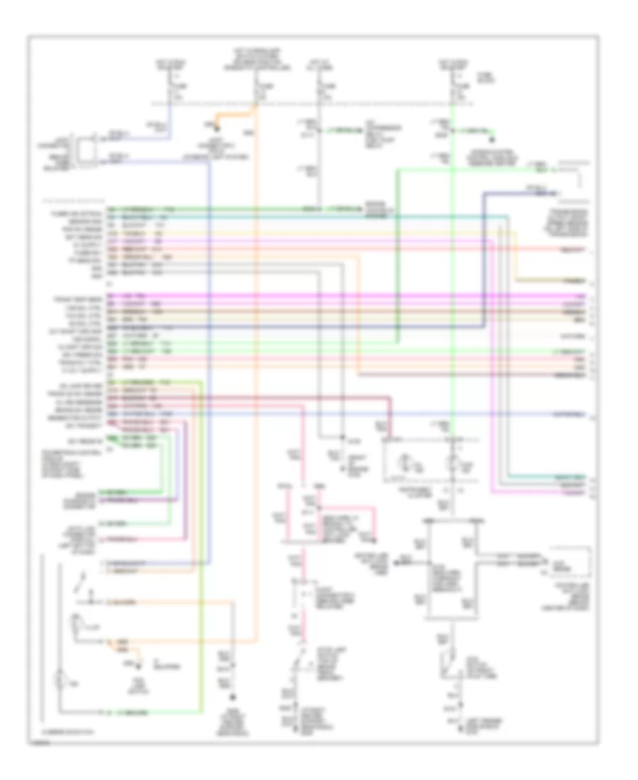 https://portal-diagnostov.com/license.html
Automotive Electricians Portal FZCO
Automotive Electricians Portal FZCO
https://portal-diagnostov.com/license.html
https://portal-diagnostov.com/license.html
Automotive Electricians Portal FZCO
Automotive Electricians Portal FZCOList of elements for 5.9L, Transmission Wiring Diagram (1 of 2) for Dodge Pickup R1997 3500:
- (eng harn, in branch to controller anti-lock brakes)
- (front of engine) g125
- (i/p right center support, near radio) g206
- (left bottom of dash)
- (left fender side shield) g100
- 4wd ind
- 4wd sense
- 4wd switch (on front axle tube)
- A/c compressor relay, fuel pump relay
- A14
- A16
- A17
- A22
- A23
- A31
- A32
- Abs
- Air bag system control module & message center
- B11
- B21
- B25
- B27
- B28
- B29
- B30
- B31
- Brake sw sense
- C13
- C17
- C24
- C25
- C27
- C29
- Connector
- Controller anti-lock brake (abs)
- Controller anti-lock brake (behind (center of dash)
- D20
- D21
- Data link connector (partial)
- Ect sens sig
- Engine controls system
- Engine diagnostic
- F18
- Fog lamp switch
- Fuse 10a
- Fuse 15a
- Fuse 5a
- Fuse block
- Fused b(+)
- Fused ign (st/run)
- G107
- G206 (i/p right center support, near radio)
- Generator output
- Gnd
- Gov press sig
- Hot at all times
- Hot in run or start
- Hot w/headlamp switch in park or head position (rheostat controlled)
- If equipped
- Illum
- Ind
- Instrument cluster
- Joint connector c (behind knee bolster)
- Joint connector c (pin 5) (interior light system)
- K125
- K22
- K30
- K54
- K88
- Mil driversense
- Mil ind
- Od lamp driver
- Od sol ctrl
- Ou shft spd sig
- Out shaft spd gnd
- Overdrive switch
- Pnk
- Pnp sw sense
- Powertrain control module (in eng compt, on right side of dash panel)
- Rwal
- S103
- S105 (eng harn, in branch for horn breakout)
- S111
- S114
- S132
- S139
- S208
- S209
- S215
- Sc1 receive
- Sci transmit
- Sensor gnd
- Stop lamp switch (top of brake pedal bracket)
- T13
- T14
- T18
- T25
- T41
- T54
- T60
- Tcc sol ctrl
- Tp sens sig
- Trans od sw sense
- Trans rly ctrl
- Trans temp sens
- Transmission output shaft speed sensor (on left side of transmission)
- V40
- Var sol ctrl
- Vss signal
- Z12
5.9L, Transmission Wiring Diagram (2 of 2) for Dodge Pickup R1997 3500
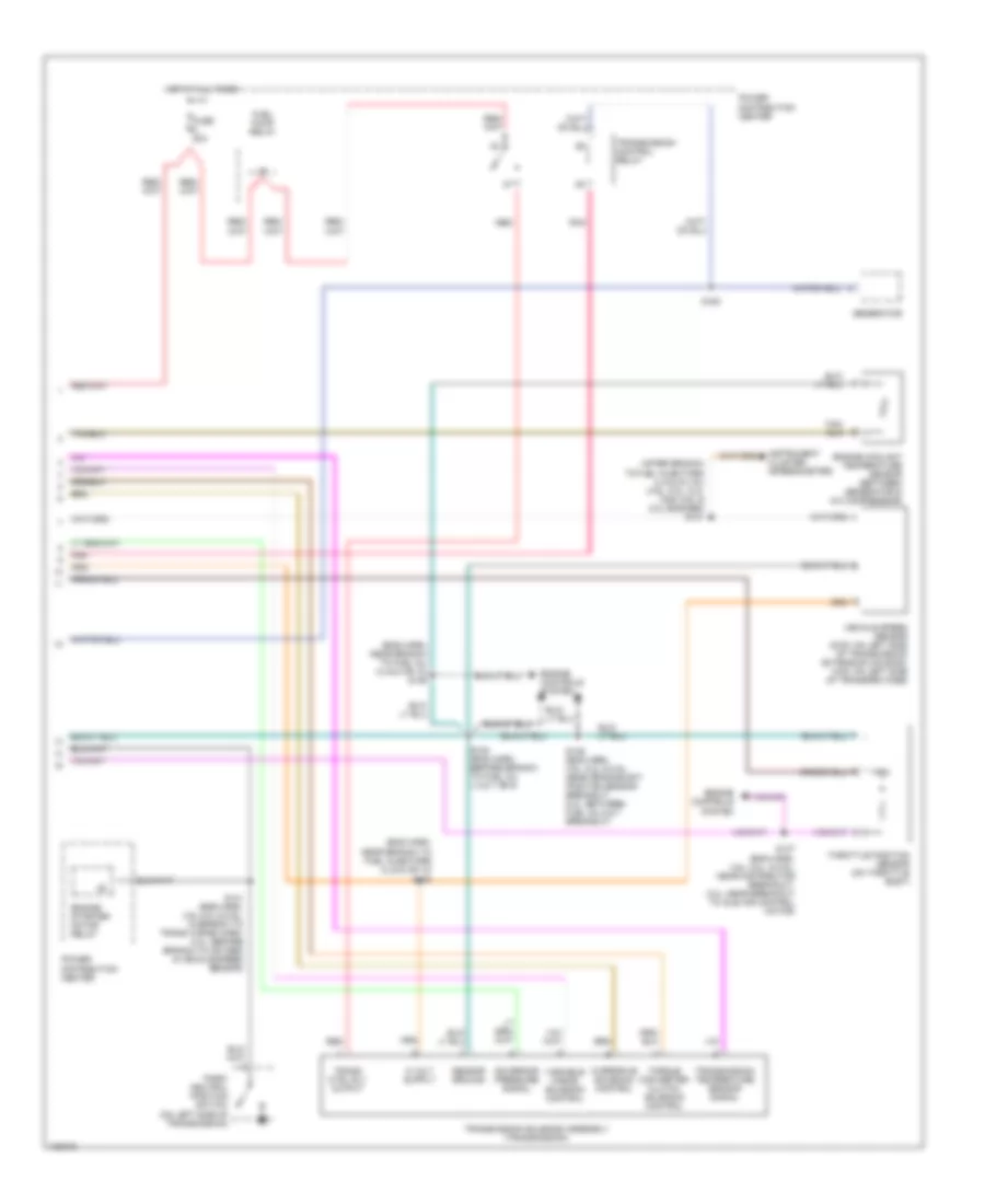 https://portal-diagnostov.com/license.html
Automotive Electricians Portal FZCO
Automotive Electricians Portal FZCO
https://portal-diagnostov.com/license.html
https://portal-diagnostov.com/license.html
Automotive Electricians Portal FZCO
Automotive Electricians Portal FZCOList of elements for 5.9L, Transmission Wiring Diagram (2 of 2) for Dodge Pickup R1997 3500:
- (after branch to fuel injectors 2,4,6,8 & (10)) (3.9l, 5.2l, 5.2l cng, 5.9l & 8.0l engines) s131
- (eng harn, near branch to fuel inj 2,4,6,8 or 10) s129
- (eng harn, near branch to fuel injectors 2,4,6,8 or 10)
- Engine controls system
- Engine coolant temperature sensor (between generator & a/c compressor)
- Engine starter motor relay
- Fuel pump relay
- Fuse 20a
- Generator
- Governor pressure signal
- Hot at all times
- Instrument cluster (speedometer)
- Overdrive solenoid control
- Park/ neutral position switch (on left side of transmission)
- Pnk
- Power distribution center
- Power distribution center
- Red
- S130
- S136 (eng harn, 3.9l, 5.2l & 5.9l: near crankshaft position sensor breakout, 8.0l: between fuel inj 5 & 7 breakout)
- S137 (eng harn, 3.9l, 5.2l, & 5.9l: near distributor breakout; 8.0l: near breakout to idle air control motor)
- S141 (eng harn, 3.9l 5.2l & 5.9l: in branch to trans wiring harn; 8.0l: before branch to oxygen & vehicle speed sensor)
- S154 (eng harn, before branch to fuel inj 1,3,5,7 or 9)
- S163
- Sensor ground
- Throttle position sensor (on throttle body)
- Torque converter clutch solenoid control
- Trans ctrl rly output
- Transmission control relay
- Transmission solenoid assembly (transmission)
- Transmission temperature sensor signal
- Variable force solenoid control
- Vehicle speed sensor (2wd: on left side of transmission extension housing, 4wd: on left side of transfer case)
WARNING SYSTEMS
Warning System Wiring Diagrams for Dodge Pickup R1997 3500
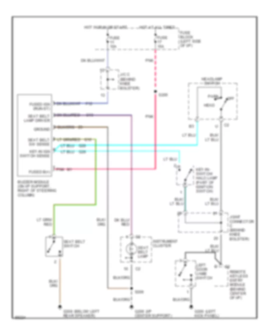 https://portal-diagnostov.com/license.html
Automotive Electricians Portal FZCO
Automotive Electricians Portal FZCO
https://portal-diagnostov.com/license.html
https://portal-diagnostov.com/license.html
Automotive Electricians Portal FZCO
Automotive Electricians Portal FZCOList of elements for Warning System Wiring Diagrams for Dodge Pickup R1997 3500:
- (behind knee bolster)
- (below left
- (i/p
- (left
- Buzzer module (on i/p support, right of steering column)
- F12
- Fuse 10a
- Fuse 15a
- Fuse block (left side of i/p)
- Fused b(+)
- G10
- G13
- G200 kick panel)
- G206 center support)
- G26
- G308 rear speaker)
- Ground
- Head
- Headlamp switch
- Hot at all times
- Hot in run or start
- Instrument cluster
- J/c c
- Joint connector c (behind knee bolster)
- Key-in ign switch sense
- Key-in- switch/ halo lamp (part of ignition switch)
- Left door jamb switch
- Off
- Park
- Pnk
- Remote keyless entry module (behind center of i/p)
- S205
- S206
- Seat belt lamp
- Seat belt sw sense
- Seat belt switch
WIPER/WASHER
Wiper/Washer Wiring Diagram for Dodge Pickup R1997 3500
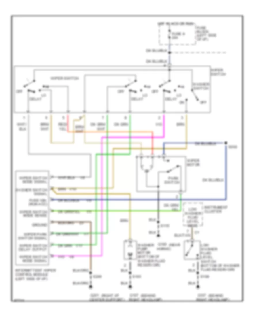 https://portal-diagnostov.com/license.html
Automotive Electricians Portal FZCO
Automotive Electricians Portal FZCO
https://portal-diagnostov.com/license.html
https://portal-diagnostov.com/license.html
Automotive Electricians Portal FZCO
Automotive Electricians Portal FZCOList of elements for Wiper/Washer Wiring Diagram for Dodge Pickup R1997 3500:
- (behind
- (near
- (right i/p
- Center support)
- Delay
- Fuse 8 20a
- Fuse block (left side of i/p)
- Fuse ign. (run-acc)
- G100
- G107
- G201
- Ground
- Horns)
- Hot in acc or run
- Instrument cluster
- Intermittent wiper control module (left side of i/p)
- Low washer fluid level indic.
- Low washer fluid level switch (bottom of washer fluid reservoir)
- Off
- Park switch
- Right headlamp)
- S103
- S108
- S115
- S202
- S206
- V10
- V17
- Washer pump motor (bottom of washer fluid reservoir)
- Washer switch
- Washer switch signal
- Wiper motor
- Wiper park switch signal
- Wiper switch
- Wiper switch delay output
- Wiper switch mode sense
- Wiper switch mode signal

 Čeština
 Dansk
Dansk Deutsch
 Ελληνικά
 English
 English
 Español
 Suomi
Suomi Français
 Français
 עברית
עברית Hrvatski
 Magyar
 Italiano
 한국어
한국어 Nederlands
 Polski
 Português
 Português
 Română
 Русский
 Slovenčina
 Slovenščina
 Svenska
 Türkçe
 中文 (中国)
