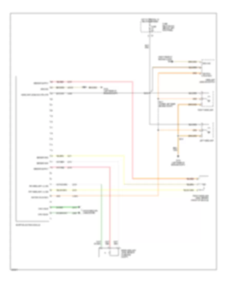
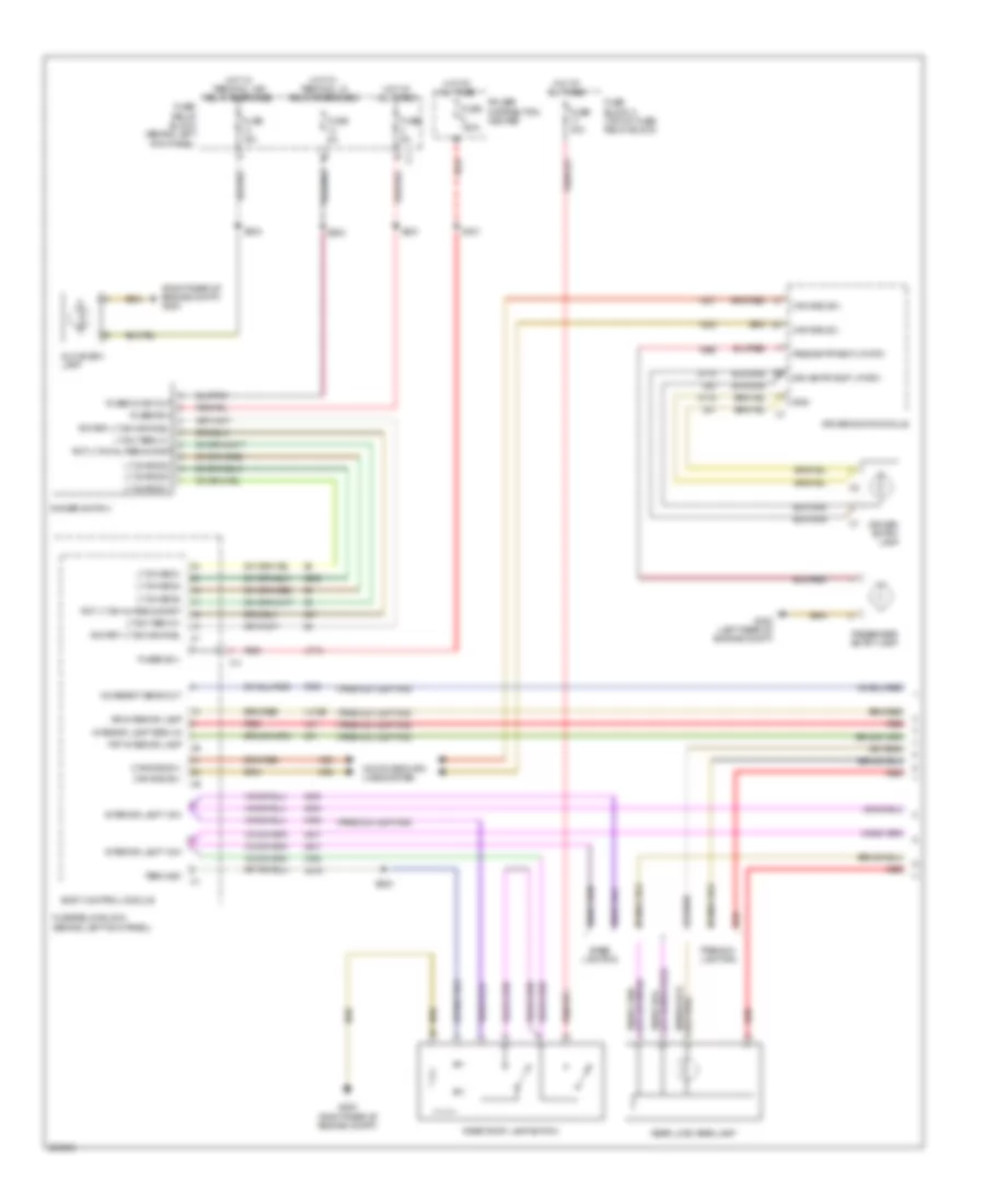
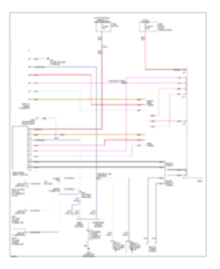
AIR CONDITIONING
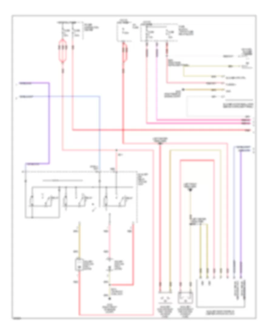
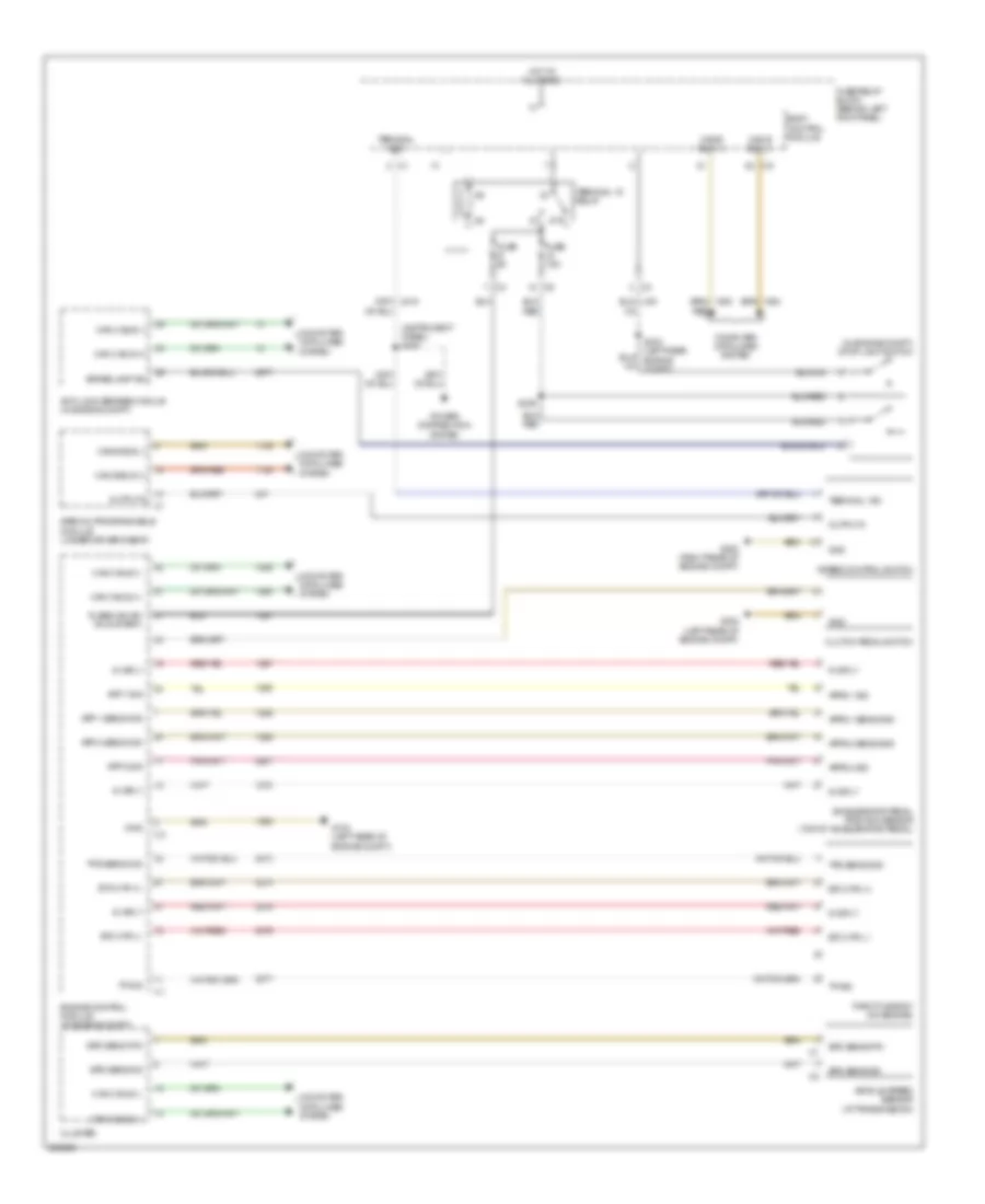
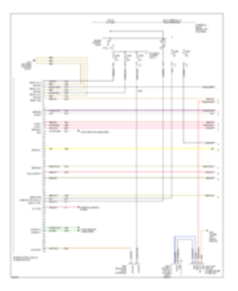
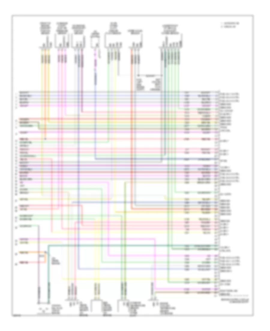
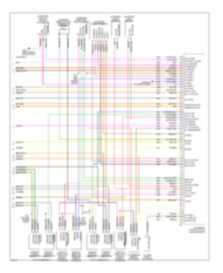
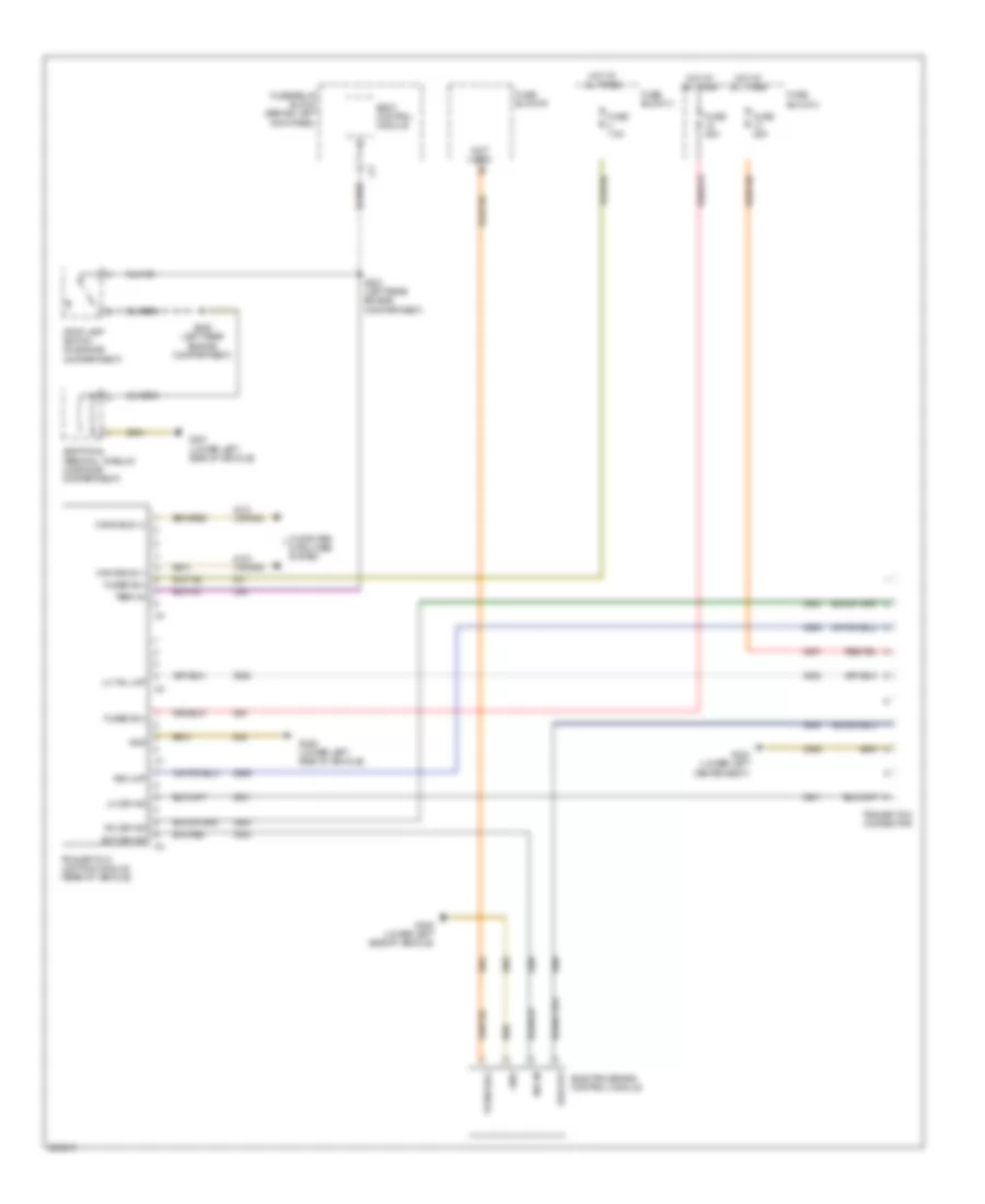
Automatic A/C Wiring Diagram (1 of 3) for Dodge Sprinter 2007 3500
 https://portal-diagnostov.com/license.html
Automotive Electricians Portal FZCO
Automotive Electricians Portal FZCO
https://portal-diagnostov.com/license.html
https://portal-diagnostov.com/license.html
Automotive Electricians Portal FZCO
Automotive Electricians Portal FZCO
List of elements for Automatic A/C Wiring Diagram (1 of 3) for Dodge Sprinter 2007 3500:
- (left center head- liner) s343
- (left side of engine compt) g104
- (right rear of
- + frt evaporator sens
- + refrigerant press sens
- + refrigerant shut-off vlv
- + temp mixing flap actr mtr
- - int air temp sens in rr of veh
- - refrigerant press sens
- - refrigerant shut-off vlv
- - temp mixing flap actr mtr
- 16a
- A/c compressor clutch
- A/c heater control
- A/c pressure sensor (in engine compt)
- Additional water pump
- Can b bus(+)
- Can b bus(-)
- Compressor ctrl vlv
- Computer data lines system
- Condenser ventilator step 1
- Condenser ventilator step 2
- Ctrl vlv compressor
- Df sig
- Engine compt)
- Engine control module (3.0l) (in engine compt)
- Fuse 10a
- Fuse 30a
- Fuse block 2 (top of fuse/ relay block)
- Fuse block 6
- Fused b(+)
- G200
- G300 (left front headliner)
- G305 (lower left side of vehicle)
- Gnd
- Heater control valve (in engine compt)
- Hot at all times
- Int air temp sens in rr of veh
- Mtr potentiometer temp mixing flap actr
- Rear recirculation door 1 actuator
- Rear recirculation door 2 actuator
- Red
- Rr a/c blwr ctrl
- Rr a/c blwr ctrl sig
- Rr heating blwr ctrl sig
- Rr heating water vlv actr mtr
- Rr heating water vlv potentiometer
- Sig refrigerant press sens
- Temp mixing flap actr mtr potentiometer
- Term 30
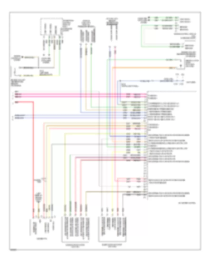
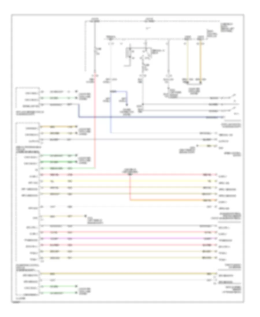
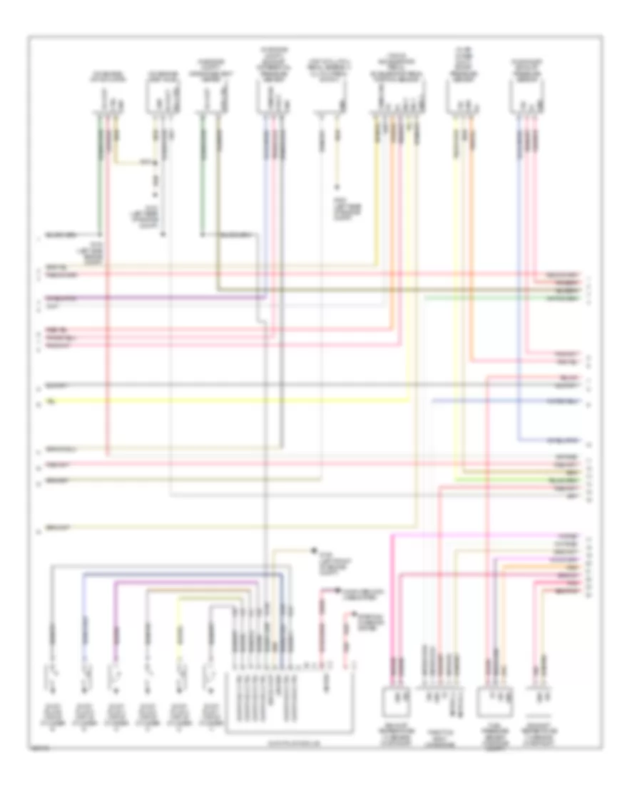
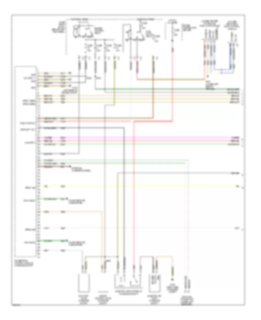
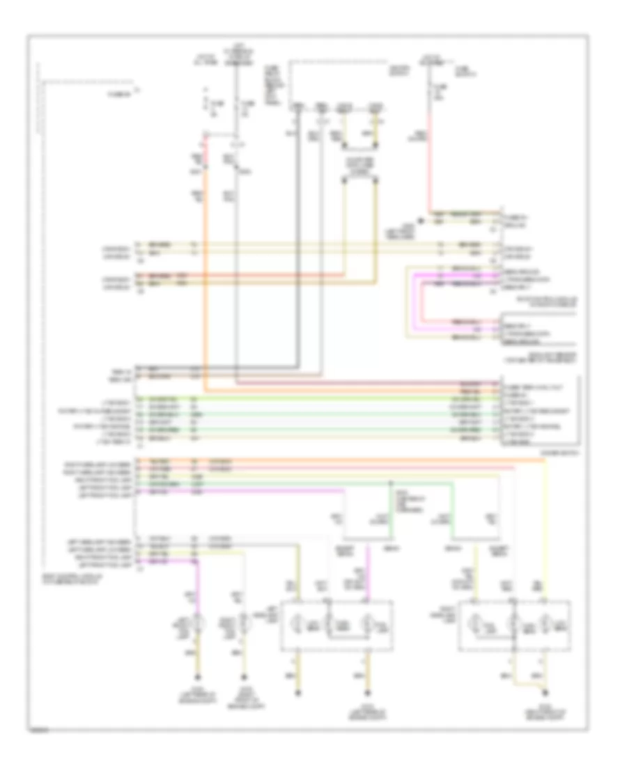
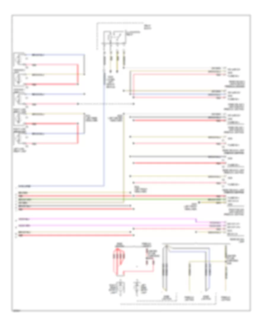
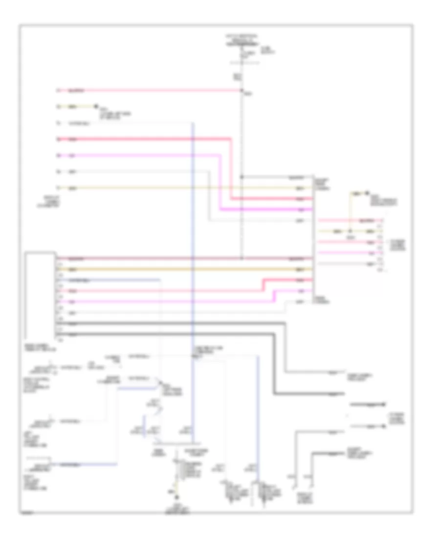
Automatic A/C Wiring Diagram (2 of 3) for Dodge Sprinter 2007 3500
 https://portal-diagnostov.com/license.html
Automotive Electricians Portal FZCO
Automotive Electricians Portal FZCO
https://portal-diagnostov.com/license.html
https://portal-diagnostov.com/license.html
Automotive Electricians Portal FZCO
Automotive Electricians Portal FZCOList of elements for Automatic A/C Wiring Diagram (2 of 3) for Dodge Sprinter 2007 3500:
- (left center headliner) s352
- (left front headliner) g300
- (on hvac) blower motor
- 12a
- 18a
- 18b
- 50a
- A/c fuse
- Auxiliary cooling roof fan 1 motor (on roof hvac)
- Auxiliary cooling roof fan 2 motor (on roof hvac)
- Auxiliary fan relay (at hvac unit)
- Auxiliary roof fan relay (center of roof a/c unit)
- Axiliary cooling fan 1 motor
- Axiliary cooling fan 2 motor
- Blower motor regulator (behind instrument panel)
- Blower mtr ctrl
- Fuse 150a
- Fuse 30a
- Fuse 7.5a
- Fuse 80a
- Fuse b(+)
- Fuse block 2 (top of fuse/ relay block)
- G102 (right front of engine compt)
- G200 (right rear of engine compt)
- Gnd
- Hot at all times
- Power distribution center
- Red
- Relay
- S211
- S212 (on front hvac unit)
- S220 (right side instrument panel)
- Ventilation 1 rly rr of veh a/c
- Ventilation 2 rly rr of veh a/c
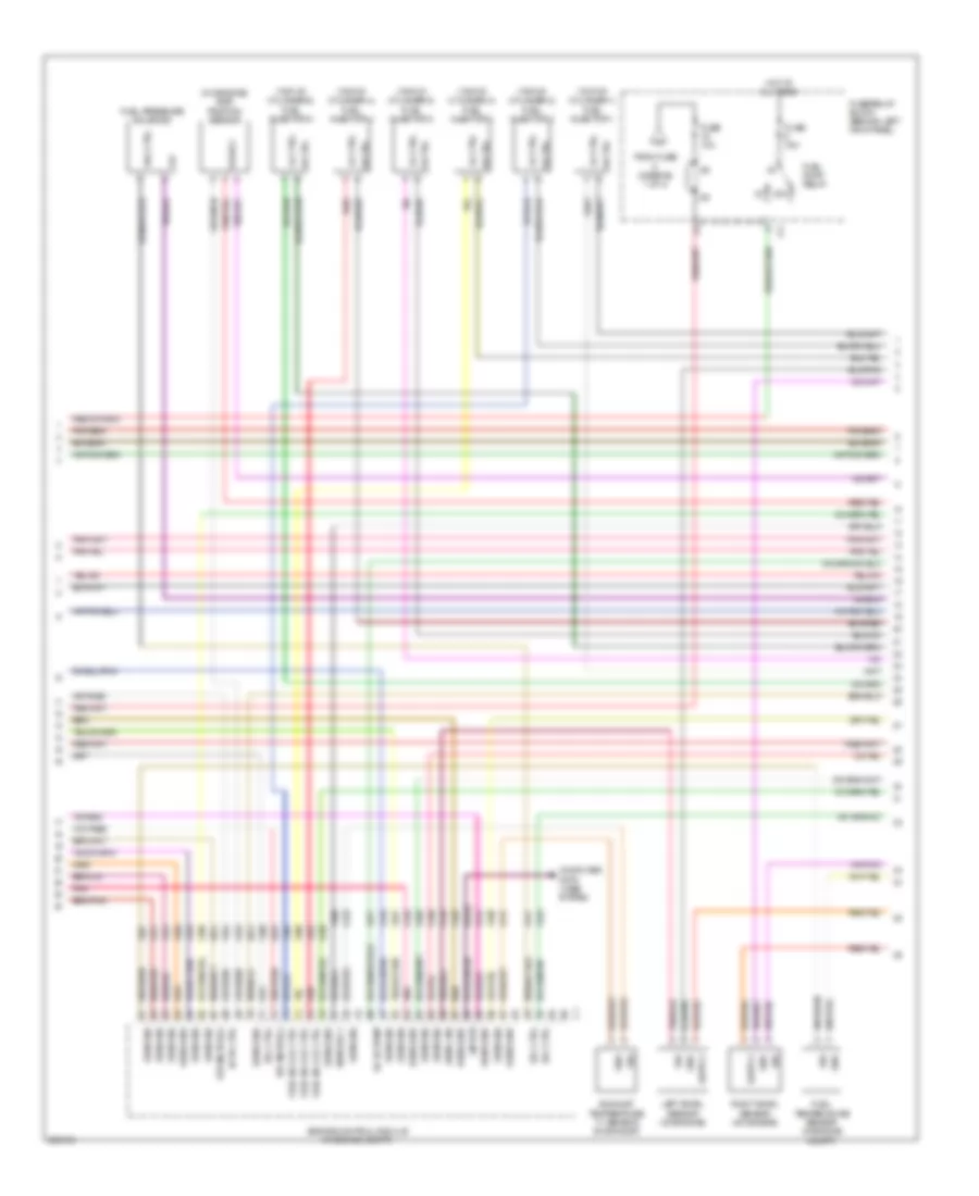
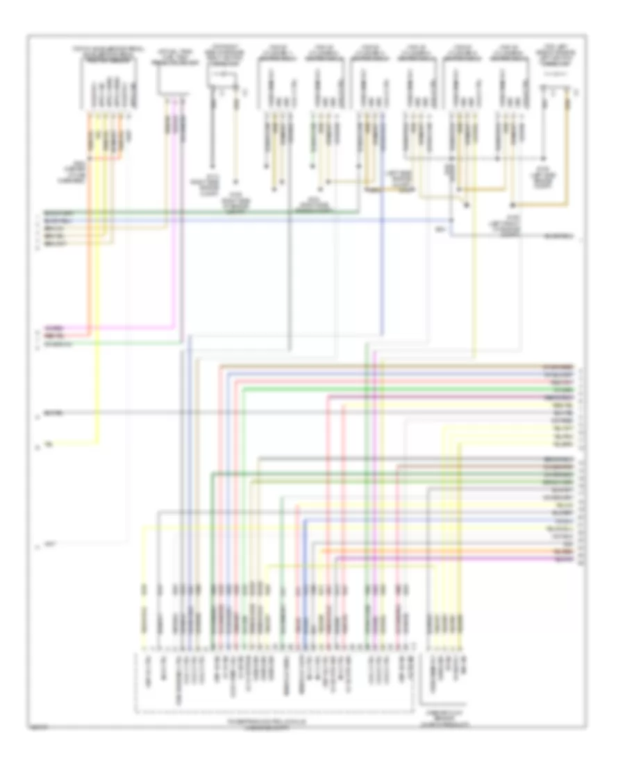
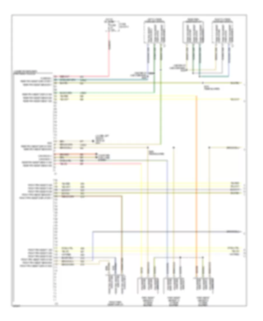
Automatic A/C Wiring Diagram (3 of 3) for Dodge Sprinter 2007 3500
 https://portal-diagnostov.com/license.html
Automotive Electricians Portal FZCO
Automotive Electricians Portal FZCO
https://portal-diagnostov.com/license.html
https://portal-diagnostov.com/license.html
Automotive Electricians Portal FZCO
Automotive Electricians Portal FZCOList of elements for Automatic A/C Wiring Diagram (3 of 3) for Dodge Sprinter 2007 3500:
- (at hvac unit) sensor temperature evaporator
- (at roof hvac unit) roof a/c pressure sensor
- (left rear of engine compt) g100
- (not used)
- + front evap sens
- + front evap sensor
- + refrigerant press sens
- + temp mixing flap actr mtr
- - front evap sens
- - front evap sensor
- - refrigerant press sens
- - temp mixing flap actr mtr
- 3.0l
- 3.5l
- A/c heater control
- Actr mtr potentiometer air distribution flap
- Air distribution flap actr mtr
- Air distribution flap actr mtr potentiometer
- Battery pwr +
- Blend door actuator (on hvac)
- Bution flap actr mtr rr heating air distri-
- C103
- Can b bus(+)
- Can b bus(-)
- Can c bus (+)
- Can c bus (-)
- Can c bus(+)
- Can c bus(-)
- Compressor clutch solenoid vlv
- Computer data lines system
- Ect sig
- Engine control module (3.0l) (in engine compt)
- Engine controls system
- Engine coolant temperature sensor (on engine)
- Flap actr mtr + temp mixing
- Flap actr mtr - temp mixing
- Fused b(+)
- Gnd
- Heater ptc
- Mode door actuator (on hvac)
- Mtr potentiometer temp mixing flap actr
- Outside air/recirculated air flap ctrl mtr
- Pnk
- Powertrain control module (3.5l) (in engine compt)
- Recirculation door actuator (on hvac)
- Red
- Refrigerant press sens sig
- Rr of veh a/c ventilator 1 rly
- Rr of veh a/c ventilator 2 rly
- S115 (left side engine compt)
- S219 (instrument panel)
- Sens gnd
- Sens sig
- Temp mixing flap actr mtr potentiometer
- Terminal 30/
- Twisted pair
- U2211
- U6102
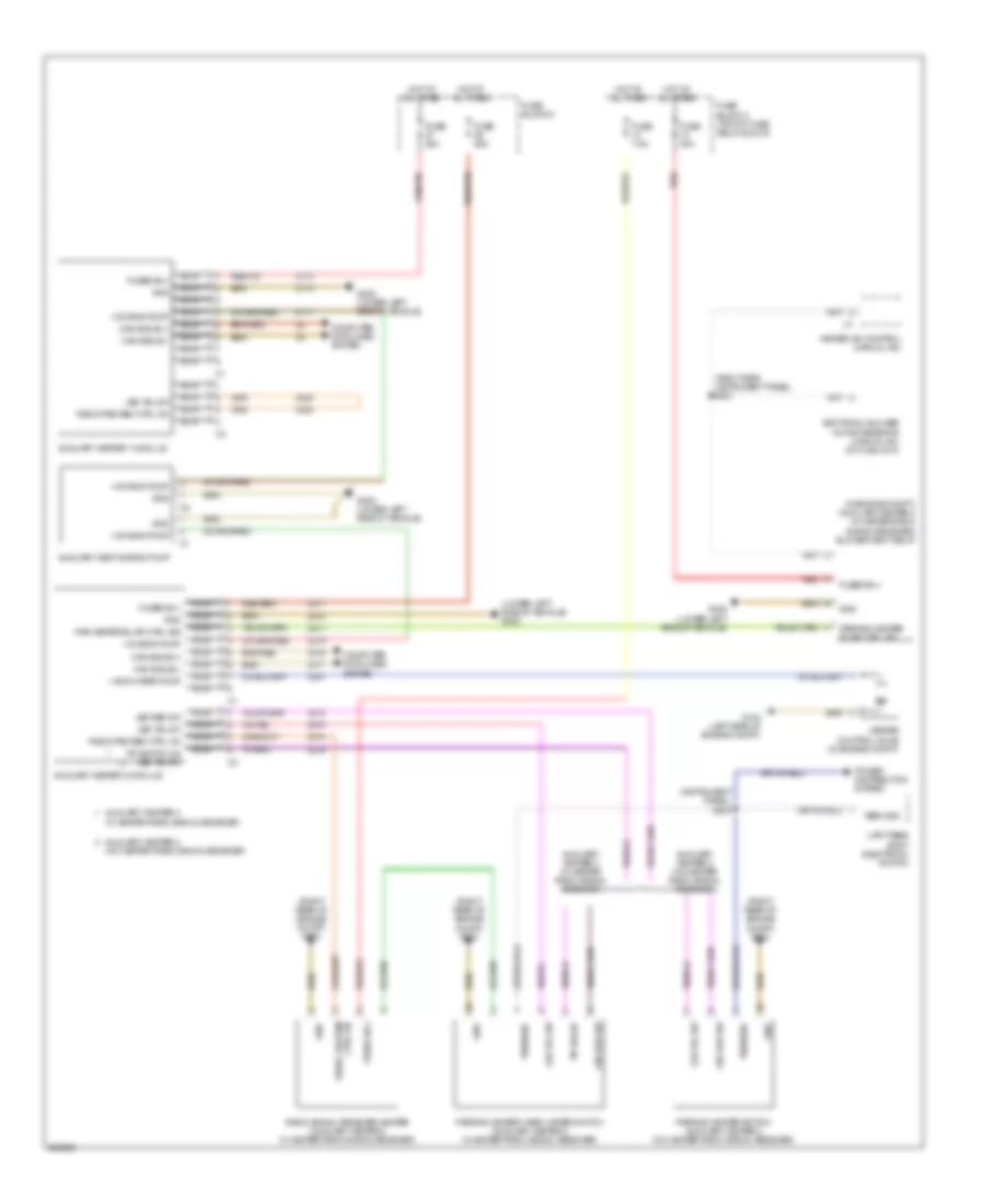
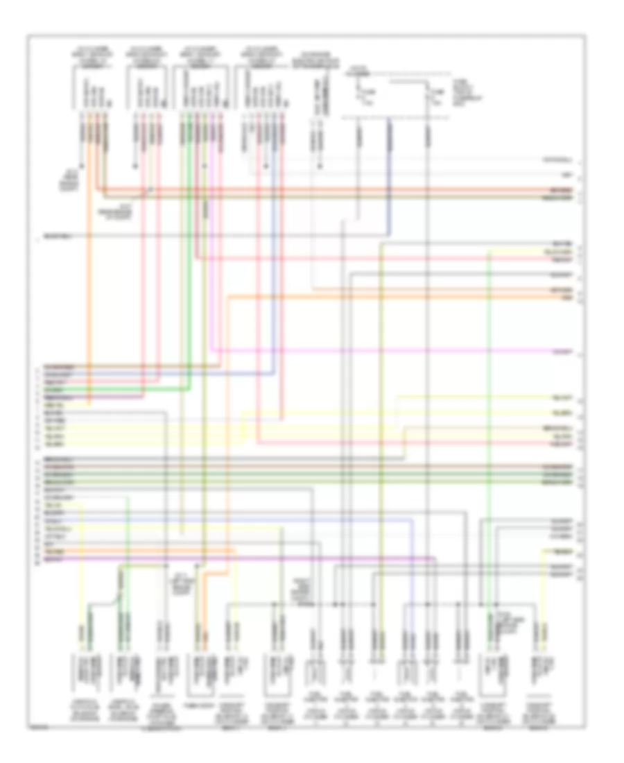
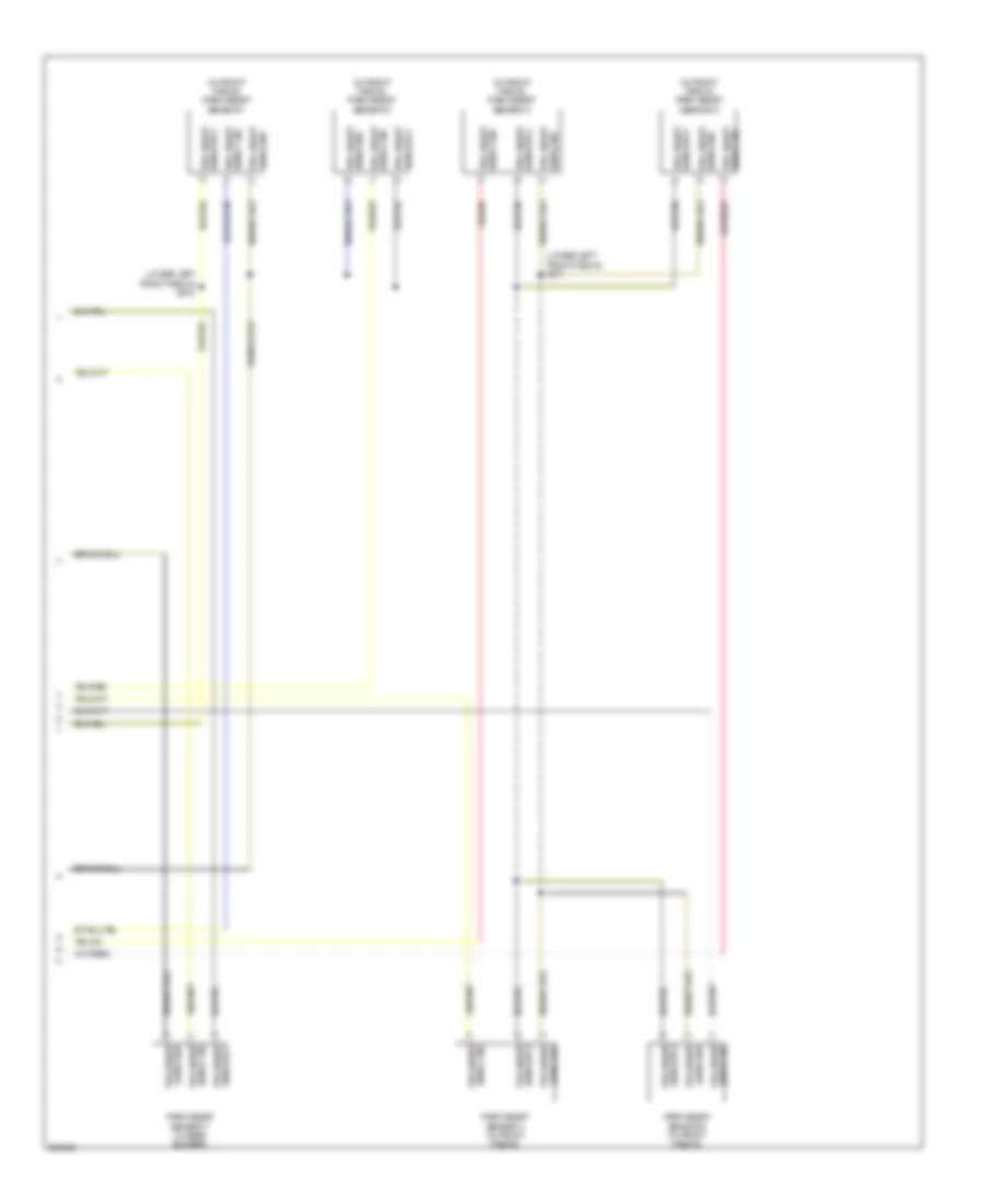
Auxiliary Heater Wiring Diagram for Dodge Sprinter 2007 3500
 https://portal-diagnostov.com/license.html
Automotive Electricians Portal FZCO
Automotive Electricians Portal FZCO
https://portal-diagnostov.com/license.html
https://portal-diagnostov.com/license.html
Automotive Electricians Portal FZCO
Automotive Electricians Portal FZCOList of elements for Auxiliary Heater Wiring Diagram for Dodge Sprinter 2007 3500:
- (in engine compt) (auxiliary heater 2 w/ heater radio signal receiver) blower vent relay
- (instrument panel) s200
- (lower left side of vehicle)
- (lower left side of vehicle) g305
- (right rear of engine compt) g200
- (right side instrument panel) s201
- + add water pump
- + dosing pump
- Additional blower motor resistor (manual a/c) (at hvac unit)
- Auxiliary heat dosing pump
- Auxiliary heater 1 module
- Auxiliary heater 2
- Auxiliary heater 2 module
- Auxiliary heater 2 w/ heater radio signal receiver
- Auxiliary heater 2 w/o heater radio signal receiver
- Can b bus(+)
- Can b bus(-)
- Computer data lines system
- Fuse 20a
- Fuse 25a
- Fuse 30a
- Fuse 7.5a
- Fuse block 2 (top of fuse/ relay block)
- Fuse block 5
- Fused b(+)
- G104 (left side of engine compt)
- G305
- G305 (lower left side of vehicle)
- Gnd
- Heater a/c control (manual a/c)
- Heater control valve (in engine compt)
- Hot at all times
- Led red sw
- Nca
- Par heater blwr ctrl sig
- Parking heater blwr ctrl sig
- Parking heater switch (auxiliary heater 2 w/o heater radio signal receiver)
- Parking heater warm water switch (auxiliary heater 2 w/ heater radio signal receiver)
- Power distribution system
- Radio fre rem ctrl on
- Radio signal receiver heater (auxiliary heater 2 w/ heater radio signal receiver)
- Red
- Term 58d
- Tip sw on
- Upfitters body electrical switch
- W/ heater radio signal receiver
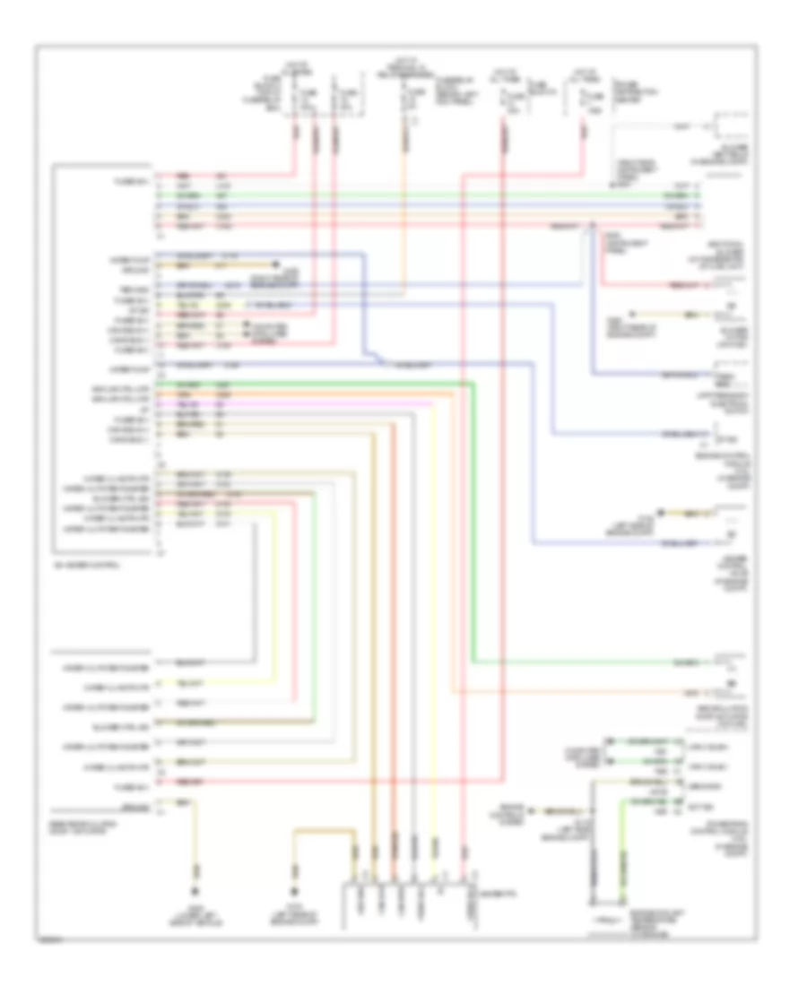
Rear Heavy Duty Air Conditioning Wiring Diagram for Dodge Sprinter 2007 3500
 https://portal-diagnostov.com/license.html
Automotive Electricians Portal FZCO
Automotive Electricians Portal FZCO
https://portal-diagnostov.com/license.html
https://portal-diagnostov.com/license.html
Automotive Electricians Portal FZCO
Automotive Electricians Portal FZCOList of elements for Rear Heavy Duty Air Conditioning Wiring Diagram for Dodge Sprinter 2007 3500:
- (right side instrument panel) s201
- A/c heater control
- Additional blower motor resistor (at hvac unit)
- Air flap ctrl mtr
- Blower ctrl sig
- Blower motor (on hvac)
- Blower vent relay (in engine compt)
- Can b bus (+)
- Can b bus (-)
- Can c bus(+)
- Can c bus(-)
- Can high
- Can low
- Computer data lines system
- Df sig
- Ect sig
- Engine control module (3.0l) (in engine compt)
- Engine controls system
- Engine coolant temperature sensor (on engine)
- Fuse 150a
- Fuse 30a
- Fuse 5a
- Fuse block 2 (top of fuse/relay box)
- Fuse block 6
- Fuse/relay block (behind left kick panel)
- Fused b(+)
- G100 (left rear of engine compt)
- G104 (left side of engine compt)
- G200 (right rear of engine compt)
- G305 (lower left side of vehicle)
- Ground
- Heater control valve (in engine compt)
- Heater ptc
- Hot at all times
- Hot w/ terminal 15 relay energized
- Power distribution center
- Powertrain control module (3.5l) (in engine compt)
- Rear recirculation door 1 actuator
- Recirculation door actuator (on hvac)
- Red
- S115 (left side engine compt)
- S200 (instrument panel)
- Sens gnd
- Term 58d
- U151
- U162
- U6102
- U815
- Upfitters body electrical switch
- Water pump
- Water vlv actr mtr
- Water vlv potentiometer
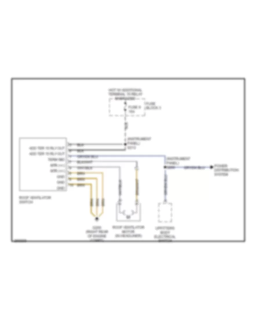
Roof Ventilator Wiring Diagram for Dodge Sprinter 2007 3500
 https://portal-diagnostov.com/license.html
Automotive Electricians Portal FZCO
Automotive Electricians Portal FZCO
https://portal-diagnostov.com/license.html
https://portal-diagnostov.com/license.html
Automotive Electricians Portal FZCO
Automotive Electricians Portal FZCOList of elements for Roof Ventilator Wiring Diagram for Dodge Sprinter 2007 3500:
- (instrument panel) s200
- (instrument panel) s213
- Add ter 15 rly out
- Fuse 9 15a
- Fuse block 3
- G200 (right rear of engine compt)
- Gnd
- Hot w/ additional terminal 15 relay energized
- Mtr (+/-)
- Power distribution system
- Roof ventilator motor (in headliner)
- Roof ventilator switch
- Term 58d
- Upfitters body electrical switch
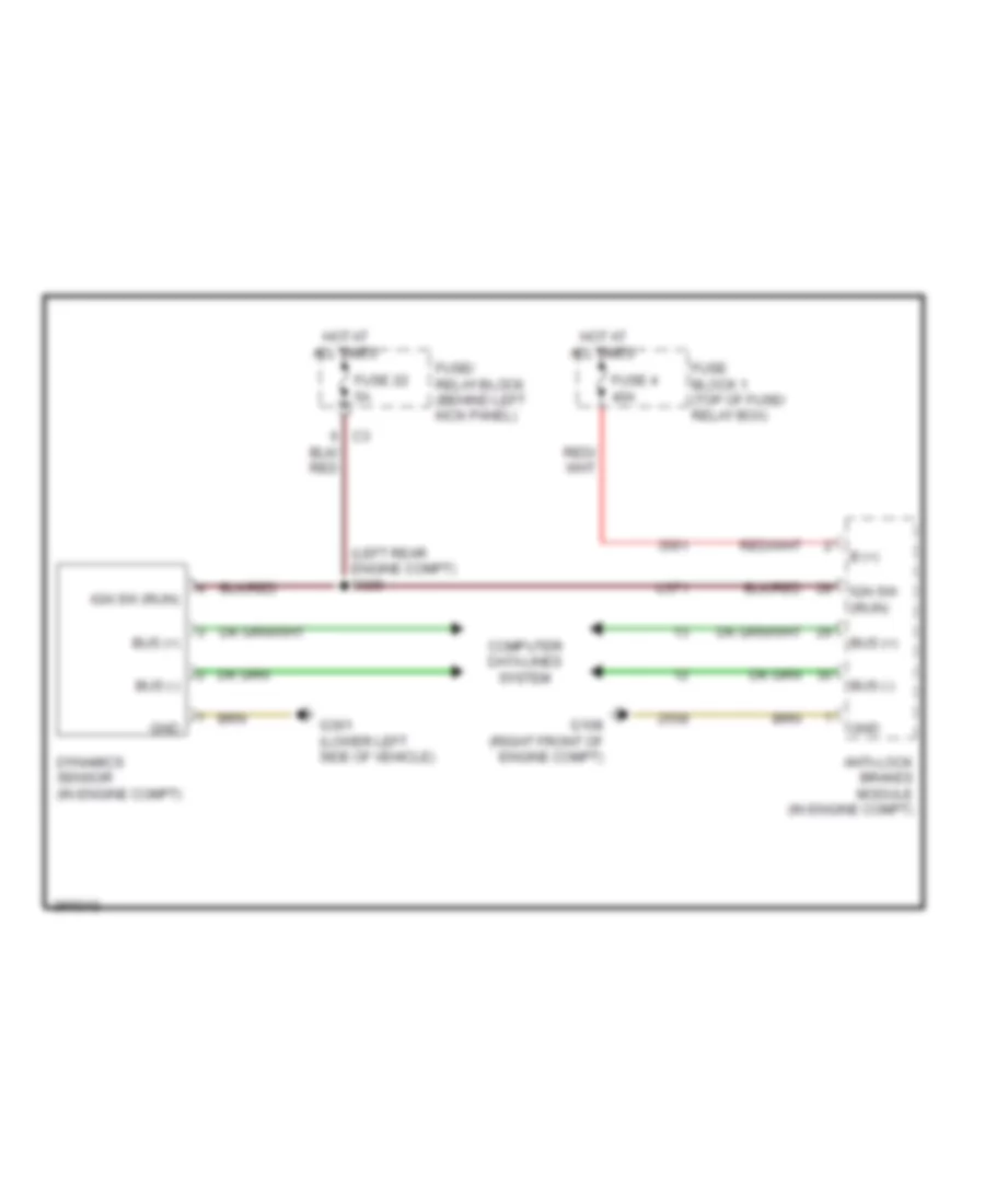
ANTI-LOCK BRAKES
Anti-lock Brakes Wiring Diagram for Dodge Sprinter 2007 3500
 https://portal-diagnostov.com/license.html
Automotive Electricians Portal FZCO
Automotive Electricians Portal FZCO
https://portal-diagnostov.com/license.html
https://portal-diagnostov.com/license.html
Automotive Electricians Portal FZCO
Automotive Electricians Portal FZCOList of elements for Anti-lock Brakes Wiring Diagram for Dodge Sprinter 2007 3500:
- (in engine compartment) stop lamp switch
- (left rear engine compartment) s303
- (right front of engine compartment) g108
- Additional terminal 15 relay (in engine compartment)
- Anti-lock brakes module (in engine compartment)
- Base
- Body control module
- Brake lamp sw
- Brake lmp sw
- Can c bus (+)
- Can c bus (-)
- Cluster
- Computer data lines system
- Dynamics sensor (in engine compartment)
- Except base
- Fuse 25a
- Fuse 40a
- Fuse 5a
- Fuse b(+) pump
- Fuse block 1 (top of fuse/relay box)
- Fuse/relay block (behind left kick panel)
- Fused b(+) vlv
- Fused ign sw out
- G102 (right front of engine compartment)
- G301 (lower left side of vehicle)
- Gnd
- Hot at all times
- Hot w/ terminal 15 relay energized
- Ign sw out
- Left front wheel speed sensor (on left front wheel)
- Left rear wheel speed sensor (on left rear wheel)
- Lf spd sens (+)
- Lf spd sens (-)
- Lr spd sens (+)
- Lr spd sens (-)
- Rf spd sens (+)
- Rf spd sens (-)
- Right front wheel speed sensor (on right front wheel)
- Right rear wheel speed sensor (on right rear wheel)
- Rr spd sens (+)
- Rr spd sens (-)
- S328
- S329 (left rear engine compartment)
- U371
- U94
ANTI-THEFT
Anti-theft Wiring Diagram for Dodge Sprinter 2007 3500
 https://portal-diagnostov.com/license.html
Automotive Electricians Portal FZCO
Automotive Electricians Portal FZCO
https://portal-diagnostov.com/license.html
https://portal-diagnostov.com/license.html
Automotive Electricians Portal FZCO
Automotive Electricians Portal FZCOList of elements for Anti-theft Wiring Diagram for Dodge Sprinter 2007 3500:
- (front center headliner) s338
- (left front headliner) g300
- (or 3347)
- (or 3348)
- Body control module (in fuse/relay block)
- Can b bus (+)
- Can b bus (-)
- Fuse 10a
- Fuse 15a
- Fuse 25a
- Fuse b(+)
- Fuse block 1 (top of fuse/relay box)
- Fuse block 2 (top of fuse/relay box)
- Fuse block 5
- Fuse/ relay block (behind left kick panel)
- Fused b(+)
- G102 (right front of engine compt)
- G104 (left side of engine compt)
- G300 (left front headliner)
- Gnd
- Ground
- Ground intrusion sensor
- Hit w/ horn relay energized
- Hood ajar sw sns
- Hood ajar switch (in engine compt)
- Horn 1 (in engine compt)
- Hot at all times
- Intrusion sens 1 clock
- Intrusion sens 1 data 1
- Intrusion sens 1 data 2
- Intrusion sens 1 data 3
- Intrusion sens 1 sply
- Intrusion sens 2 data
- Intrusion sens 3 data
- Intrusion sens 3 data intrusion sensor 3 (rear of headliner)
- Intrusion sens rtn
- Intrusion sens sply
- Intrusion sensor 1 (front of headliner)
- Intrusion sensor 2 (center of headliner)
- Movement sens input
- Movement snes input
- Roof control module (in roof console)
- S339 (left front headliner)
- Siren (in engine compt)
- Siren ctrl
- U245
- U762
- Vtss ind lamp
BODY CONTROL MODULES
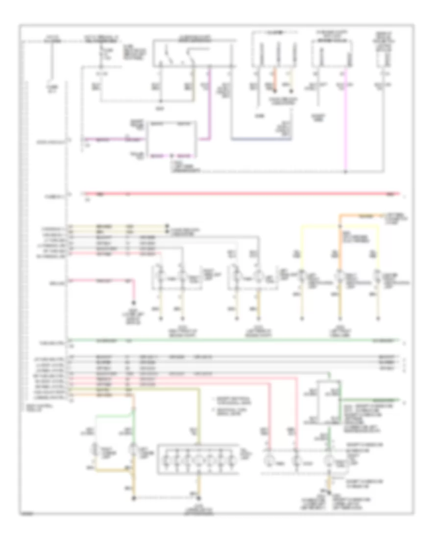
Body Computer Module Wiring Diagram for Dodge Sprinter 2007 3500
 https://portal-diagnostov.com/license.html
Automotive Electricians Portal FZCO
Automotive Electricians Portal FZCO
https://portal-diagnostov.com/license.html
https://portal-diagnostov.com/license.html
Automotive Electricians Portal FZCO
Automotive Electricians Portal FZCOList of elements for Body Computer Module Wiring Diagram for Dodge Sprinter 2007 3500:
- (left rear of engine compt)
- (left rear of engine compt) g302
- (not used)
- (or 1469)
- (or 1945)
- (or 2330)
- (or 2331)
- (or 2429)
- (or 2430)
- (or 25)
- (or 2555)
- (or 26)
- (or 3337)
- (or 3430)
- (or 3431)
- (or 3592)
- (or 3602)
- (or 3604)
- (or 4486)
- (or 456)
- (or 581)
- (or 64)
- (or 70)
- (or 71)
- (or 72)
- (or 73)
- (or 86)
- (or 88)
- (or u1036)
- (or u3011)
- (or u3012)
- (or u38)
- (or u41)
- Ambient sens rtn
- Ambient sens sig
- Anti-lock brakes & exterior lights systems
- Anti-theft system
- Back-up lmp
- Body control module (in fuse/relay block)
- Brk fluid sw rtn
- Brk fluid sw sns
- Brk lt sw
- Brk wear sens
- Can b bus (+)
- Can b bus (-)
- Computer data lines system
- Coolant sw rtn
- Coolant sw sns
- Defogger system
- Door locks system
- Engine controls system
- Exterior lights system
- Flap lh rh
- Fr screen washer
- Frt int lmp
- Frt wip rly
- Fuel lvl sens rtn
- Fuel lvl sens sig
- Fuse 25a
- Fuse 7.5a
- Fuse 80a
- Fuse/relay block (behind left kick panel)
- Fused b(+)
- G103
- Gnd
- Hdlp washer
- Headlights system
- Hi mount lmp
- Horn rly
- Horns system
- Hot at all times
- Htd rr wind rly 1
- Htd rr wind rly 2
- Htd wndshd rly
- In sens
- In term 15
- Instrument cluster system
- Int lmp sw 1
- Int lmp sw 2
- Int lp term 30
- Interior lights system
- Lf dir ind
- Lf fog lmp
- Lf mirr dir ind
- Lh dr ajar sw
- Lh dr ajar sw sns
- Lh hdlp hi beam
- Lh hdlp lo beam
- Lh parking lps
- Lh side dr sns
- Lh stop lmp
- License lmp
- Lr drv wind close
- Lr drv wind open
- Lr park lmp
- Lr turn sig
- Lt sw bcd1
- Lt sw bcd2
- Lt sw bcd3
- Lt sw ter 31
- Mirrors system
- Not used
- Out sens
- Parking brk
- Pass dr ajar sw
- Pass dr lk drv
- Pass dr unlk drv
- Pass wind drv dn
- Pass wind drv up
- Pass wind sw
- Pass wind sw mux
- Power distribution center
- Power distribution system
- Power windows system
- Red
- Rev lmp
- Rf dir ind
- Rf fog lmp
- Rf mirr dir ind
- Rh dr ajar sns
- Rh dr latch sns
- Rh hdlp hi beam
- Rh hdlp lo beam
- Rh parking lps
- Rh stp lmp
- Rotary lt sw
- Rr dr ajar sw sns
- Rr dr lck
- Rr drv wind close
- Rr drv wind open
- Rr fog lmp
- Rr int lmp
- Rr park lmp
- Rr screen washer
- Rr turn sig
- Rr wind det 1
- Rr wind detection 2
- Rr wiper 1 lh
- Rr wiper 2 lh
- Rr/side drs lck
- Rr/side drs unlck
- Side marker 5
- Starting/charging system
- Term 15r
- Term 31b fr wip
- Term 58d
- Terminal 15
- Terminal 15r
- U2116
- U2117
- U261
- U3013
- U3014
- U337
- U382
- U43
- U432
- U815
- U94
- Warning system
- Wash fluid lvl sw
- Wash fluid sw sns
- Wiper/washer system
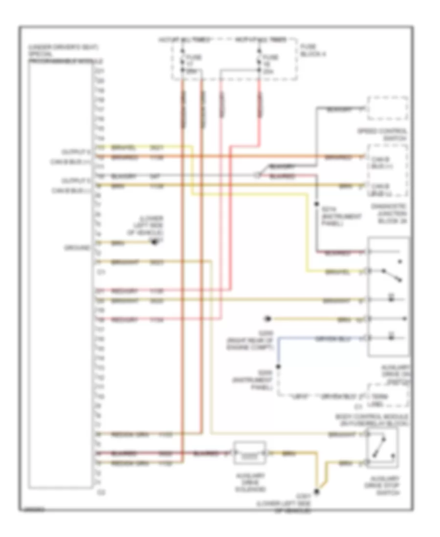
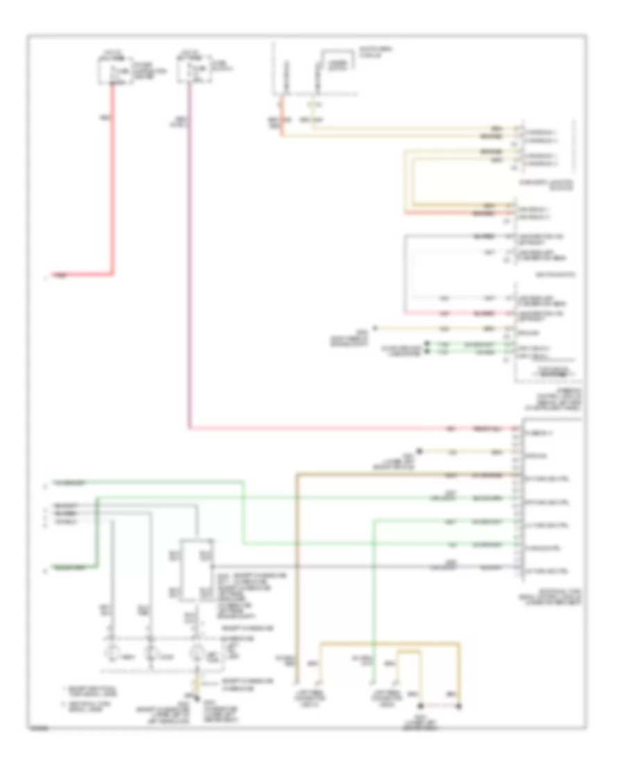
Programmable Special Module Wiring Diagram for Dodge Sprinter 2007 3500
 https://portal-diagnostov.com/license.html
Automotive Electricians Portal FZCO
Automotive Electricians Portal FZCO
https://portal-diagnostov.com/license.html
https://portal-diagnostov.com/license.html
Automotive Electricians Portal FZCO
Automotive Electricians Portal FZCOList of elements for Programmable Special Module Wiring Diagram for Dodge Sprinter 2007 3500:
- (lower left side of vehicle) g301
- (under driver's seat) special programmable module
- Auxiliary drive on switch
- Auxiliary drive solenoid
- Auxiliary drive stop switch
- Body control module (in fuse/relay block)
- Can b bus (+)
- Can b bus (-)
- Diagnostic junction block 24
- Fuse 25a
- Fuse block 4
- G200 (right rear of engine compt)
- G301 (lower left side of vehicle)
- Ground
- Hot at all times
- Output 5
- Output 6
- S200 (instrument panel)
- S214 (instrument panel)
- Speed control switch
- Term 58d
- U815
COMPUTER DATA LINES
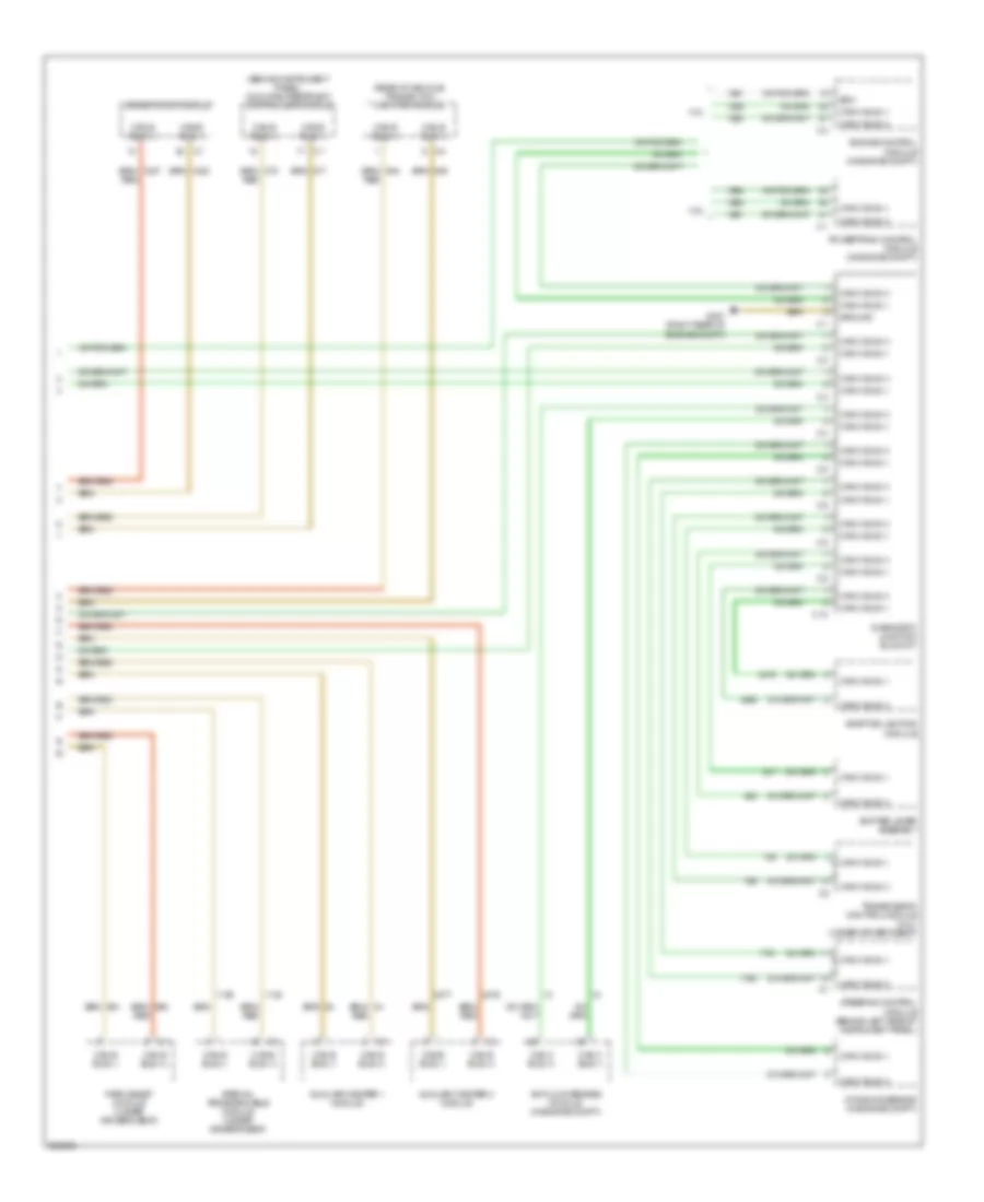
Computer Data Lines Wiring Diagram (1 of 2) for Dodge Sprinter 2007 3500
 https://portal-diagnostov.com/license.html
Automotive Electricians Portal FZCO
Automotive Electricians Portal FZCO
https://portal-diagnostov.com/license.html
https://portal-diagnostov.com/license.html
Automotive Electricians Portal FZCO
Automotive Electricians Portal FZCOList of elements for Computer Data Lines Wiring Diagram (1 of 2) for Dodge Sprinter 2007 3500:
- (automatic a/c)
- (base)
- (in fuse/relay block) body control module
- (in roof console) roof control module
- (manual a/c)
- (sound 20)
- A/c heater control
- C11
- Can b bus (+)
- Can b bus (-)
- Can c bus (+)
- Can c bus (-)
- Data link connector (under left side dash)
- Diagnostic can c (+)
- Diagnostic can c (-)
- Diagnostic junction block 24
- Diagnostic junction block 25
- Diagnostic junction block 26
- Fuse /relay block (behind left kick panel)
- Fuse 14 5a
- Fuse 2 10a
- Fuse block 1 (top of fuse/relay box)
- G301 (lower left side of vehicle)
- Hot at all times
- Ignition switch
- Instrument cluster
- Radio
- Red
- Switch bank module
- Tire pressure monitor module (under driver's seat)
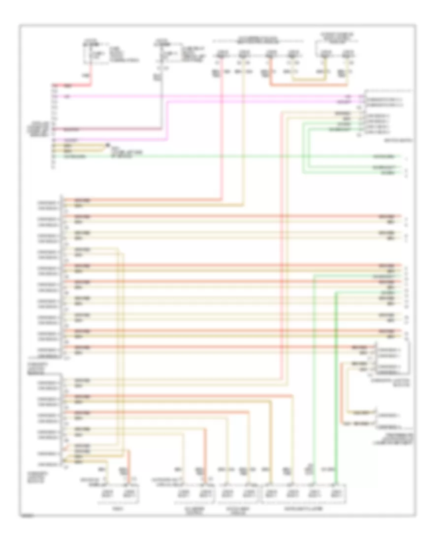
Computer Data Lines Wiring Diagram (2 of 2) for Dodge Sprinter 2007 3500
 https://portal-diagnostov.com/license.html
Automotive Electricians Portal FZCO
Automotive Electricians Portal FZCO
https://portal-diagnostov.com/license.html
https://portal-diagnostov.com/license.html
Automotive Electricians Portal FZCO
Automotive Electricians Portal FZCOList of elements for Computer Data Lines Wiring Diagram (2 of 2) for Dodge Sprinter 2007 3500:
- (behind instrument panel) occupant restraint controller module
- (rear of vehicle) trailer tow lighting module
- 3.0l
- 3.5l
- Adaptive lighting module
- Anti-lock brakes module (in engine compt)
- Auxiliary heater 1 module
- Auxiliary heater 2 module
- C10
- Can b bus (+)
- Can b bus (-)
- Can c bus (+)
- Can c bus (-)
- Diagnostic junction block 27
- Driver door module
- Dynamics sensor (in engine compt)
- Ecm
- Engine control module (in engine compt)
- G307 (right rear of engine compt)
- Ground
- Park assist module (under driver's seat)
- Powertrain control module (in engine compt)
- Red
- Shifter lever assembly
- Special programmable module (under driver's seat)
- Steering control module (behind left side of instrument panel)
- Transmission control module (3.0l) (under driver's seat)
COOLING FAN
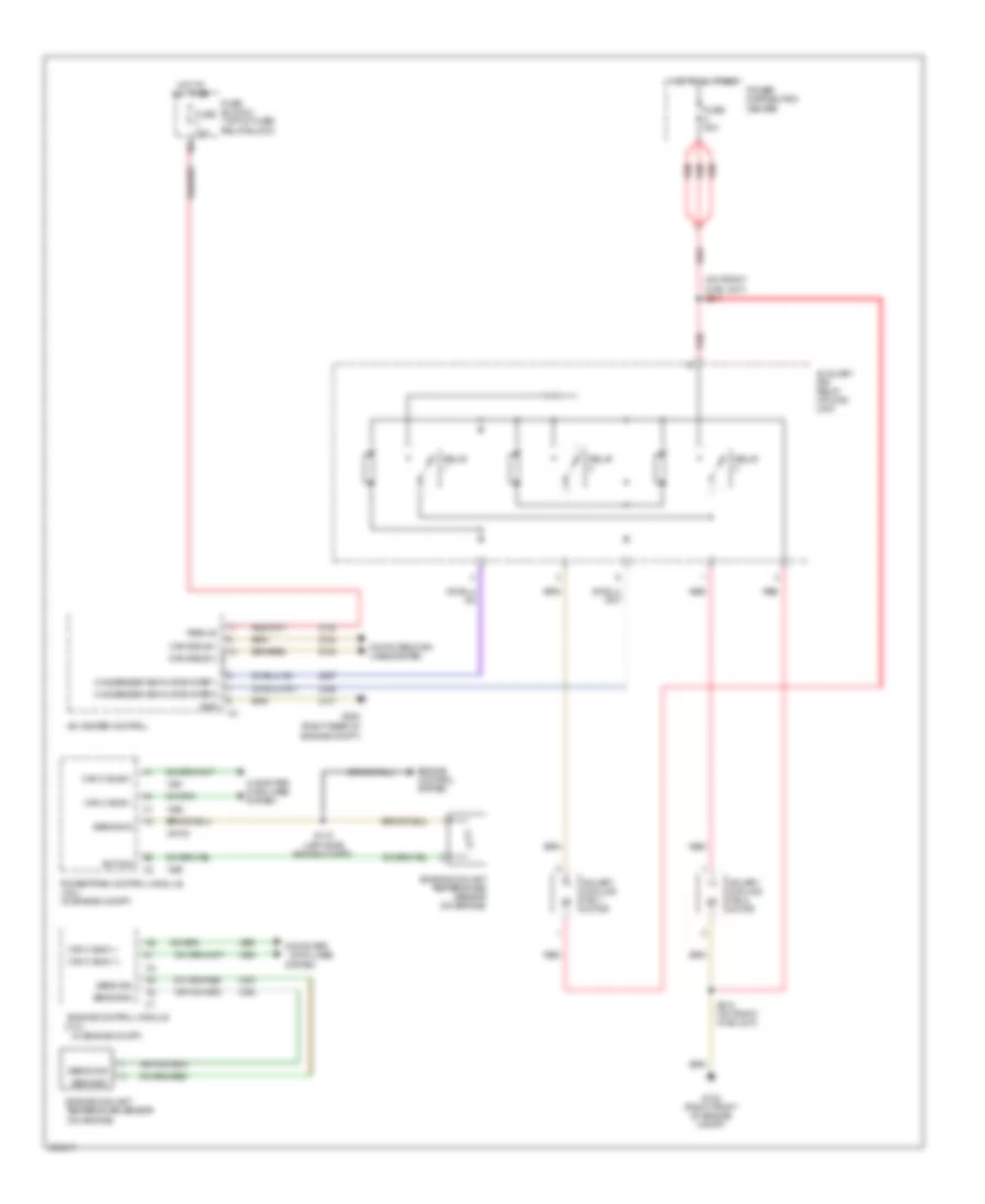
Cooling Fan Wiring Diagram for Dodge Sprinter 2007 3500
 https://portal-diagnostov.com/license.html
Automotive Electricians Portal FZCO
Automotive Electricians Portal FZCO
https://portal-diagnostov.com/license.html
https://portal-diagnostov.com/license.html
Automotive Electricians Portal FZCO
Automotive Electricians Portal FZCOList of elements for Cooling Fan Wiring Diagram for Dodge Sprinter 2007 3500:
- (3.0l)
- (in engine compt)
- (on engine)
- (on front hvac unit) s211
- 16a
- A/c heater control
- Auxiliary fan relay (at hvac unit)
- Axiliary cooling fan 1 motor
- Axiliary cooling fan 2 motor
- Can b bus(+)
- Can b bus(-)
- Can c bus (+)
- Can c bus (-)
- Can c bus(+)
- Can c bus(-)
- Computer
- Computer data lines system
- Condenser ventilator step 1
- Condenser ventilator step 2
- Data lines
- Ect sig
- Engine compt)
- Engine control module
- Engine control system
- Engine coolant
- Engine coolant temperature sensor (on engine)
- Fuse 10a
- Fuse 80a
- Fuse block 2 (top of fuse/ relay block)
- G102 (right front of engine compt)
- G200 (right rear of
- Gnd
- Hot at all times
- Power distribution center
- Powertrain control module (3.5l) (in engine compt)
- Red
- Relay
- S115 (left side engine compt)
- S212 (on front hvac unit)
- Sens gnd
- Sens sig
- System
- Temperature sensor
- Term 30
- U6102
CRUISE CONTROL
3.0L
3.0L, Cruise Control Wiring Diagram for Dodge Sprinter 2007 3500
 https://portal-diagnostov.com/license.html
Automotive Electricians Portal FZCO
Automotive Electricians Portal FZCO
https://portal-diagnostov.com/license.html
https://portal-diagnostov.com/license.html
Automotive Electricians Portal FZCO
Automotive Electricians Portal FZCOList of elements for 3.0L, Cruise Control Wiring Diagram for Dodge Sprinter 2007 3500:
- (in engine compt) stop light switch
- (instrument panel) s200
- 5v sply
- 87a
- Accelerator pedal position sensor (top of accelerator pedal)
- Anti-lock brakes module (in engine compt)
- App 1 sens gnd
- App 1 sig
- App 2 sens gnd
- App 2 sig
- Apps 1 sens gnd
- Apps 1 sig
- Apps 2 sens gnd
- Apps 2 sig
- Body control module
- Brake lamp sw
- Can b bus (+)
- Can b bus (-)
- Can c bus (+)
- Can c bus (-)
- Cluster
- Clutch pedal switch
- Computer data lines system
- Engine control module (in engine compt)
- Etc mtr (+)
- Etc mtr (-)
- Fuse 5a
- Fuse 7.5a
- Fuse/relay block (behind left kick panel)
- Fused ign sw (run-start)
- G103 (left rear of engine compt)
- G200 (right rear of engine compt)
- G302 (left rear of engine compt)
- Gnd
- Hot at all times
- Output 5
- Power distribution system
- Red
- S329
- Spd sens rtn
- Spd sens sig
- Special programmable module (under driver's seat)
- Speed control switch
- Terminal 15 relay
- Terminal 15d
- Terminal 58d
- Throttle body (on engine)
- Tp sig
- Tps sens gnd
- Vehicle speed sensor (at transmission)
3.5L
3.5L, Cruise Control Wiring Diagram for Dodge Sprinter 2007 3500
 https://portal-diagnostov.com/license.html
Automotive Electricians Portal FZCO
Automotive Electricians Portal FZCO
https://portal-diagnostov.com/license.html
https://portal-diagnostov.com/license.html
Automotive Electricians Portal FZCO
Automotive Electricians Portal FZCOList of elements for 3.5L, Cruise Control Wiring Diagram for Dodge Sprinter 2007 3500:
- (center of cab overhead) s304
- 5v sply
- 87a
- Accelerator pedal position sensor (top of accelerator pedal)
- Anti-lock brakes module (in engine compt)
- App 1 sens gnd
- App 1 sig
- App 2 sens gnd
- App 2 sig
- Apps 1 sens gnd
- Apps 1 sig
- Apps 2 sens gnd
- Apps 2 sig
- Body control module
- Brake lamp sw
- Can b bus (+)
- Can b bus (-)
- Can c bus (+)
- Can c bus (-)
- Cluster
- Computer data lines system
- Etc mtr (+)
- Etc mtr (-)
- Fuse 10a
- Fuse 7.5a
- Fuse/relay block (behind left kick panel)
- G103 (left rear of engine compt)
- G200 (right rear of engine compt)
- Gnd
- Hot at all times
- Output 5
- Power distribution system
- Powertrain control module (in engine compt)
- Red
- S200
- S329
- Spd sens rtn
- Spd sens sig
- Special programmable module (under driver's seat)
- Speed control switch
- Stop light switch (in engine compt)
- Terminal 15 relay
- Terminal 15d
- Terminal 58d
- Throttle body (on engine)
- Tp sens gnd
- Tp sig 1
- Tp sig 2
- U786
- Vehicle speed sensor (at transmission)
DEFOGGERS
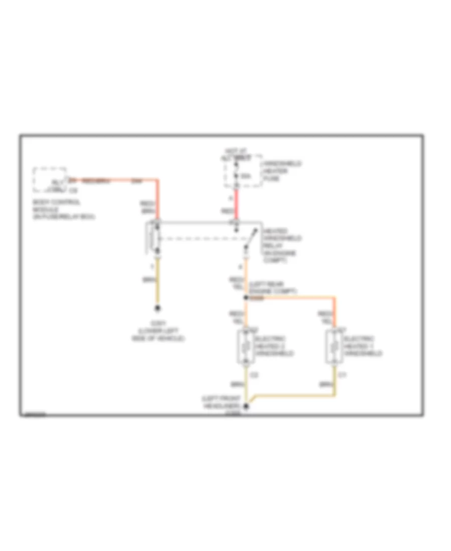
Heated Windshield Wiring Diagram for Dodge Sprinter 2007 3500
 https://portal-diagnostov.com/license.html
Automotive Electricians Portal FZCO
Automotive Electricians Portal FZCO
https://portal-diagnostov.com/license.html
https://portal-diagnostov.com/license.html
Automotive Electricians Portal FZCO
Automotive Electricians Portal FZCOList of elements for Heated Windshield Wiring Diagram for Dodge Sprinter 2007 3500:
- (left front headliner) g300
- 30a
- Body control module (in fuse/relay box)
- Electric heated 1 windshield
- Electric heated 2 windshield
- G301 (lower left side of vehicle)
- Heated windshield relay (in engine compt)
- Hot at all times
- Red
- Rly ctrl c9
- Windshield heater fuse
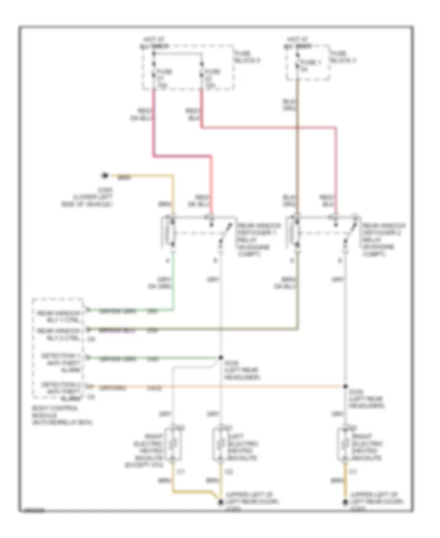
Rear Defogger Wiring Diagram for Dodge Sprinter 2007 3500
 https://portal-diagnostov.com/license.html
Automotive Electricians Portal FZCO
Automotive Electricians Portal FZCO
https://portal-diagnostov.com/license.html
https://portal-diagnostov.com/license.html
Automotive Electricians Portal FZCO
Automotive Electricians Portal FZCOList of elements for Rear Defogger Wiring Diagram for Dodge Sprinter 2007 3500:
- (upper left of left rear door) g303
- Anti-theft alarm
- Body control module (in fuse/relay box)
- Detection 1
- Detection 2
- Fuse 1 5a
- Fuse 15a
- Fuse block 3
- Fuse block 5
- G305 (lower left side of vehicle)
- Hot at all times
- Left electric heated backlite
- Rear window defogger 1 relay (in engine compt)
- Rear window defogger 2 relay (in engine compt)
- Rear window rly 1 ctrl
- Rear window rly 2 ctrl c9
- Right electric heated backlite
- Right electric heated backlite (except ata)
- S335 (left rear headliner)
- S336 (left rear headliner)
- U43
- U432
ELECTRONIC POWER STEERING
Electronic Power Steering Wiring Diagram for Dodge Sprinter 2007 3500
 https://portal-diagnostov.com/license.html
Automotive Electricians Portal FZCO
Automotive Electricians Portal FZCO
https://portal-diagnostov.com/license.html
https://portal-diagnostov.com/license.html
Automotive Electricians Portal FZCO
Automotive Electricians Portal FZCOList of elements for Electronic Power Steering Wiring Diagram for Dodge Sprinter 2007 3500:
- (left rear engine compt) s328
- Anti-lock brakes module (in engine compt)
- B (+)
- Bus (+)
- Bus (-)
- Computer data lines system
- Dynamics sensor (in engine compt)
- Fuse 22 5a
- Fuse 4 40a
- Fuse block 1 (top of fuse/ relay box)
- Fuse/ relay block (behind left kick panel)
- G108 (right front of engine compt)
- G301 (lower left side of vehicle)
- Gnd
- Hot at all times
- Ign sw (run)
- U371
ENGINE PERFORMANCE
3.0L DIESEL
3.0L Diesel, Engine Performance Wiring Diagram (1 of 4) for Dodge Sprinter 2007 3500
 https://portal-diagnostov.com/license.html
Automotive Electricians Portal FZCO
Automotive Electricians Portal FZCO
https://portal-diagnostov.com/license.html
https://portal-diagnostov.com/license.html
Automotive Electricians Portal FZCO
Automotive Electricians Portal FZCOList of elements for 3.0L Diesel, Engine Performance Wiring Diagram (1 of 4) for Dodge Sprinter 2007 3500:
- 5v sply
- 87a
- Apps sig 1
- Apps sig 2
- Asd rly ctrl
- Asd rly out
- Body control module (in fuse/ relay block)
- Can bus (+)
- Can bus (-)
- Computer data lines system
- Ecm
- Egr swichover valve (on engine)
- Engine control module (in engine compt)
- Engine control relay
- Fuel pump module (under center of vehicle)
- Fuel pump rly
- Fuse 10a
- Fuse 20a
- Fuse 5a
- Fuse/relay block (behind left kick panel)
- Fused ignition sw out
- G103 (left rear of engine compt)
- G301 (lower left side of vehicle)
- Gnd
- Ground
- Hot at all times
- Hot w/ terminal 15 relay energized
- Lvl sig
- Rly ctrl
- Rly out
- Rtn
- S302
- Sens
- Sens 1 gnd
- Sens 2 gnd
- Sens gnd
- Sens sig
- Starting/charging system
- To fuse 16 (diagram 3 of 4)
- U777
- Valve ctrl
- Vlv ctrl
3.0L Diesel, Engine Performance Wiring Diagram (2 of 4) for Dodge Sprinter 2007 3500
 https://portal-diagnostov.com/license.html
Automotive Electricians Portal FZCO
Automotive Electricians Portal FZCO
https://portal-diagnostov.com/license.html
https://portal-diagnostov.com/license.html
Automotive Electricians Portal FZCO
Automotive Electricians Portal FZCOList of elements for 3.0L Diesel, Engine Performance Wiring Diagram (2 of 4) for Dodge Sprinter 2007 3500:
- (in air intake duct) boost pressure sensor
- (in engine compt) crankcase vent heater
- (in engine compt) exhaust differential pressure sensor
- (in exhaust) exhaust pressure sensor
- (on engine) egr valve
- (on engine) vnt actuator
- (top of accelerator pedal) accelerator pedal position sensor
- (top of clutch pedal assembly) clutch pedal switch
- 5 volt
- Asd rly out
- Computer data lines system
- Ctrl
- Exhaust temperature 1/2 sensor (in exhaust)
- Exhaust temperature 1/3 sensor (in exhaust)
- Fuel pressure sensor (in engine compt)
- G103 (left rear of engine compt)
- G109 (left front of engine compt)
- G302 (left rear of engine compt)
- Glow plug 1 (top of cylinder 1)
- Glow plug 1 ctrl
- Glow plug 2 (top of cylinder 2)
- Glow plug 2 ctrl
- Glow plug 3 (top of cylinder 3)
- Glow plug 3 ctrl
- Glow plug 4 (top of cylinder 4)
- Glow plug 4 ctrl
- Glow plug 5 (top of cylinder 5)
- Glow plug 5 ctrl
- Glow plug 6 (top of cylinder 6)
- Glow plug 6 ctrl
- Glow plug module
- Gnd
- Gnd 2
- Ground
- Htr ctrl
- Lin bus
- Motor (+)
- Motor (-)
- Pnk
- Red
- Rly out
- S101
- S102 (left side engine compt)
- Sens gnd
- Sens sig
- Sig
- Sol ctrl
- Starting/ charging system
- Throttle body (on engine)
- U2032
- U748
3.0L Diesel, Engine Performance Wiring Diagram (3 of 4) for Dodge Sprinter 2007 3500
 https://portal-diagnostov.com/license.html
Automotive Electricians Portal FZCO
Automotive Electricians Portal FZCO
https://portal-diagnostov.com/license.html
https://portal-diagnostov.com/license.html
Automotive Electricians Portal FZCO
Automotive Electricians Portal FZCOList of elements for 3.0L Diesel, Engine Performance Wiring Diagram (3 of 4) for Dodge Sprinter 2007 3500:
- (on engine) egr position sensor
- (top of cylinder 1) fuel injector 1
- (top of cylinder 2) fuel injector 2
- (top of cylinder 3) fuel injector 3
- (top of cylinder 4) fuel injector 4
- (top of cylinder 5) fuel injector 5
- (top of cylinder 6) fuel injector 6
- 02 1/2 pump
- 12v
- 5v sply
- 87a
- Actr ctrl
- Computer data lines system
- Engine control module (in engine compt)
- Etc motor(+)
- Etc motor(-)
- Exhaust temperature 1/1 sensor (in exhaust)
- From fuse (diagram 1 of 4)
- Fuel inj 2 lo ctrl
- Fuel inj 3 lo ctrl
- Fuel inj 4 lo ctrl
- Fuel pressure solenoid
- Fuel pump relay
- Fuel temperature sensor (in engine compt)
- Fuse 10a
- Fuse 15a
- Fuse/relay block (behind left kick panel)
- Gnd
- Hi ctrl
- Hot at all times
- Left swirl sensor (on engine)
- Lin bus
- Lo ctrl
- Pnk
- Red
- Right swirl sensor (on engine)
- Sens gnd
- Sens sig
- Sens sig 1
- Sig
- Sol ctrl
- Swirl sig
- U2032
3.0L Diesel, Engine Performance Wiring Diagram (4 of 4) for Dodge Sprinter 2007 3500
 https://portal-diagnostov.com/license.html
Automotive Electricians Portal FZCO
Automotive Electricians Portal FZCO
https://portal-diagnostov.com/license.html
https://portal-diagnostov.com/license.html
Automotive Electricians Portal FZCO
Automotive Electricians Portal FZCOList of elements for 3.0L Diesel, Engine Performance Wiring Diagram (4 of 4) for Dodge Sprinter 2007 3500:
- (front of engine) camshaft position sensor
- (in air intake duct) mass air flow sensor
- (in engine compt) inlet air pressure sensor
- (on diesel engine)
- (on engine) crankshaft position sensor
- (under front of vehicle, in exhaust) oxygen sensor
- 12v sply
- 5v sply
- A/c heater control
- Automatic a/c
- Common rail pump (top of engine)
- Ctrl rtn
- Current
- Df sig
- Egr tempe- rature sensor (on engine)
- Engine control module (in engine compt)
- Engine coolant temperature sensor (on engine)
- Fuel inj 1 hi ctrl
- Fuel inj 1 lo ctrl
- Fuel inj 2 hi ctrl
- Fuel inj 3 hi ctrl
- Fuel inj 4 hi ctrl
- Fuel inj 5 hi ctrl
- Fuel inj 5 lo ctrl
- Fuel inj 6 hi ctrl
- Fuel inj 6 lo ctrl
- Gnd
- Htr ctrl
- Intake air temperature sensor (in air intake duct)
- Manual ac
- O2 1/2 pump
- O2 1/2 rtn
- O2 1/2 sig
- Oil tempe- rature sensor (on engine)
- Pump
- Right swirl sig
- Rtn
- S103 (left side engine compt)
- S120
- S327 (on main body (hls) harness)
- Sens gnd
- Sens sig
- Sens sig 2
- Sig
- Sig 1
- Sig 2
- Sply
- Tp sig
- U760
- Water in fuel sensor
3.5L
3.5L, Engine Performance Wiring Diagram (1 of 4) for Dodge Sprinter 2007 3500
 https://portal-diagnostov.com/license.html
Automotive Electricians Portal FZCO
Automotive Electricians Portal FZCO
https://portal-diagnostov.com/license.html
https://portal-diagnostov.com/license.html
Automotive Electricians Portal FZCO
Automotive Electricians Portal FZCOList of elements for 3.5L, Engine Performance Wiring Diagram (1 of 4) for Dodge Sprinter 2007 3500:
- (in fuse/ relay box) body control module
- (under center of vehicle) fuel pump module
- 87a
- Air pump 1 rly
- Apps 1 sens
- Apps 1 sig
- Apps 2 sens
- Apps 2 sig
- Can c bus+
- Can c bus-
- Computer data lines system
- Data link connector (under left side dash)
- Electric air pump (in engine compt)
- Electric air pump relay (in engine compt)
- Engine control relay
- Fill lvl
- Fuel pump relay
- Fuel pump rly
- Fuse 10a
- Fuse 15a
- Fuse 20a
- Fuse 80a
- Fuse/ relay block (behind left kick panel)
- Fused b+
- G103 (left rear of engine compt)
- G105 (right side of engine compt)
- G301 (lower left side of vehicle)
- Gnd
- Ground
- Hot at all times
- Lvl sens
- Power distribution center
- Powertrain control module (in engine compt)
- Purge control valve (in engine compt)
- Red
- Rly out air pump
- S302
- S305
- S306
- Shut-off valve (in engine compt)
- Starting/ charging system
- U786
- U799
- Volt sply 1
3.5L, Engine Performance Wiring Diagram (2 of 4) for Dodge Sprinter 2007 3500
 https://portal-diagnostov.com/license.html
Automotive Electricians Portal FZCO
Automotive Electricians Portal FZCO
https://portal-diagnostov.com/license.html
https://portal-diagnostov.com/license.html
Automotive Electricians Portal FZCO
Automotive Electricians Portal FZCOList of elements for 3.5L, Engine Performance Wiring Diagram (2 of 4) for Dodge Sprinter 2007 3500:
- (at fuel tank) fuel tank pressure sensor
- (in air intake duct)
- (left side engine compt) s105
- (top left side of engine) left ignition capacitor
- (top of accelerator pedal) accelerator pedal position sensor
- (top of cylinder 1) ignition coil 1
- (top of cylinder 2) ignition coil 2
- (top of cylinder 3) ignition coil 3
- (top of cylinder 4) ignition coil 4
- (top of cylinder 5) ignition coil 5
- (top of cylinder 6) ignition coil 6
- (top right side of engine) right ignition capacitor
- Apps 1 sens
- Apps 1 sig
- Apps 2 sens
- Apps 2 sig
- Cmp 1/1 ctrl
- Cmp 1/2 ctrl
- Cmp 1/2 sig
- Cmp 2/2 sig
- Coil 1 ctrl
- Coil 2 ctrl
- Coil 3 ctrl
- Coil 4 ctrl
- Coil 5 ctrl
- Coil 6 ctrl
- Fused main rly
- G105 (right side of engine compt)
- G106 (left front of engine compt)
- Gnd
- Iat sig
- Inj 1 ctrl
- Inj 4 ctrl
- Inj 5 ctrl
- Inj 6 ctrl
- Maf sig
- Manifold flow
- Manifold swirl
- Mass air flow sensor
- O2 1/1 return
- O2 1/1 sig
- O2 1/2 htr gnd
- O2 2/1 pump cell
- O2 2/1 sig
- O2 2/2 htr gnd
- O2 2/2 sig
- Powertrain control module (in engine compt)
- Pwr steering ctrl
- S104 (right side engine compt)
- S109 (left side engine compt)
- S110 (right side engine compt)
- S304 (center of cab overhead)
- S321
- Sens gnd
- U6101
- U6102
3.5L, Engine Performance Wiring Diagram (3 of 4) for Dodge Sprinter 2007 3500
 https://portal-diagnostov.com/license.html
Automotive Electricians Portal FZCO
Automotive Electricians Portal FZCO
https://portal-diagnostov.com/license.html
https://portal-diagnostov.com/license.html
Automotive Electricians Portal FZCO
Automotive Electricians Portal FZCOList of elements for 3.5L, Engine Performance Wiring Diagram (3 of 4) for Dodge Sprinter 2007 3500:
- (in cylinder bank 1 exhaust) oxygen 1/1 sensor
- (in cylinder bank 1 exhaust) oxygen 1/2 sensor
- (in cylinder bank 2 exhaust) oxygen 2/1 sensor
- (in cylinder bank 2 exhaust) oxygen 2/2 sensor
- (on engine) electric air pump switchover valve
- (right side engine compt) s106
- Camshaft position solenoid 1/1 (on cylinder bank 1)
- Camshaft position solenoid 1/2 (on cylinder bank 1)
- Camshaft position solenoid 2/1 (on cylinder bank 2)
- Camshaft position solenoid 2/2 (on cylinder bank 2)
- Ctrl cmp 1/1
- Ctrl cmp 1/2
- Ctrl cmp 2/1
- Ctrl cmp 2/2
- Eco ctrl pwr steering
- Elec air pump
- Flow ctrl manifold
- Fuel injector (top of cylinder 1)
- Fuel injector (top of cylinder 2)
- Fuel injector (top of cylinder 3)
- Fuel injector (top of cylinder 4)
- Fuel injector (top of cylinder 5)
- Fuel injector (top of cylinder 6)
- Fuse 7.5a
- Fuse block 1 (top of fuse/relay box)
- Fused main rly
- Hot at all times
- Htr ctrl thermostat
- Htr gnd
- Htr rtn
- Htr sply
- Manifold flow valve solenoid (on engine)
- Manifold swirl valve solenoid (on engine)
- Power steering pump valve (at power steering pump)
- Pump cell
- Pump current
- Return
- Rly out fused main
- S107 (rear engine of compt)
- S108 (left side engine compt)
- S111 (left side engine compt)
- S112 (rear engine compt)
- Sig
- Swirl ctrl manifold
- Thermostat
3.5L, Engine Performance Wiring Diagram (4 of 4) for Dodge Sprinter 2007 3500
 https://portal-diagnostov.com/license.html
Automotive Electricians Portal FZCO
Automotive Electricians Portal FZCO
https://portal-diagnostov.com/license.html
https://portal-diagnostov.com/license.html
Automotive Electricians Portal FZCO
Automotive Electricians Portal FZCOList of elements for 3.5L, Engine Performance Wiring Diagram (4 of 4) for Dodge Sprinter 2007 3500:
- (at electric air pump) air pump flow sensor
- (left
- (on cylinder bank 1)
- (on cylinder bank 2)
- (on engine) crankshaft position sensor
- (on engine) engine coolant temperature sensor
- (on engine) knock sensor 1
- (on engine) knock sensor 2
- (on engine) throttle body
- 5 volt
- Air pump
- Air pump flow sig
- Air pump sw ctrl
- Camshaft position sensor 1/1
- Camshaft position sensor 1/2
- Camshaft position sensor 2/1
- Camshaft position sensor 2/2
- Ckp sig
- Cmp 1/1 sig
- Cmp 1/2 sig
- Cmp 2/1 ctrl
- Cmp 2/1 sig
- Cmp 2/2 ctrl
- Cmp 2/2 sig
- Ect motor +
- Ect motor -
- Ect sig
- Etc motor +
- Etc motor -
- Fused main rly out
- G105 (right side of engine compt)
- Gnd
- Iat sig
- Inj 2 ctrl
- Inj 3 ctrl
- Ks 1 return
- Ks 1 sig
- Ks 2 return
- Ks 2 sig
- Ks i return
- Lin bus
- Maf sig
- Manifold absolute pressure sensor (on engine)
- Manifold swirl
- Manifold swirl position sig 1
- Manifold swirl position sig 2
- Manifold swirl valve position sensor 1 (on engine)
- Manifold swirl valve position sensor 2 (on engine)
- Map sig
- O2 1/1 htr ctrl
- O2 1/1 pump
- O2 1/1 pump cell
- O2 1/2 sig
- O2 2/1 htr ctrl
- O2 2/1 pump
- O2 2/1 return
- O2 return
- Oil level sig
- Oil level switch (on engine)
- Oil pressure sensor (on engine)
- Oil pressure sig
- Pnk
- Powertrain control module (in engine compt)
- S113 (left side engine compt)
- S114 (left side engine compt)
- S115
- S116
- Sens gnd
- Side engine compt)
- Starting/ charging system
- Thermostat htr
- Tp sens gnd
- Tp sig 1
- Tp sig 2
- U778
- U779
- U854
EXTERIOR LIGHTS
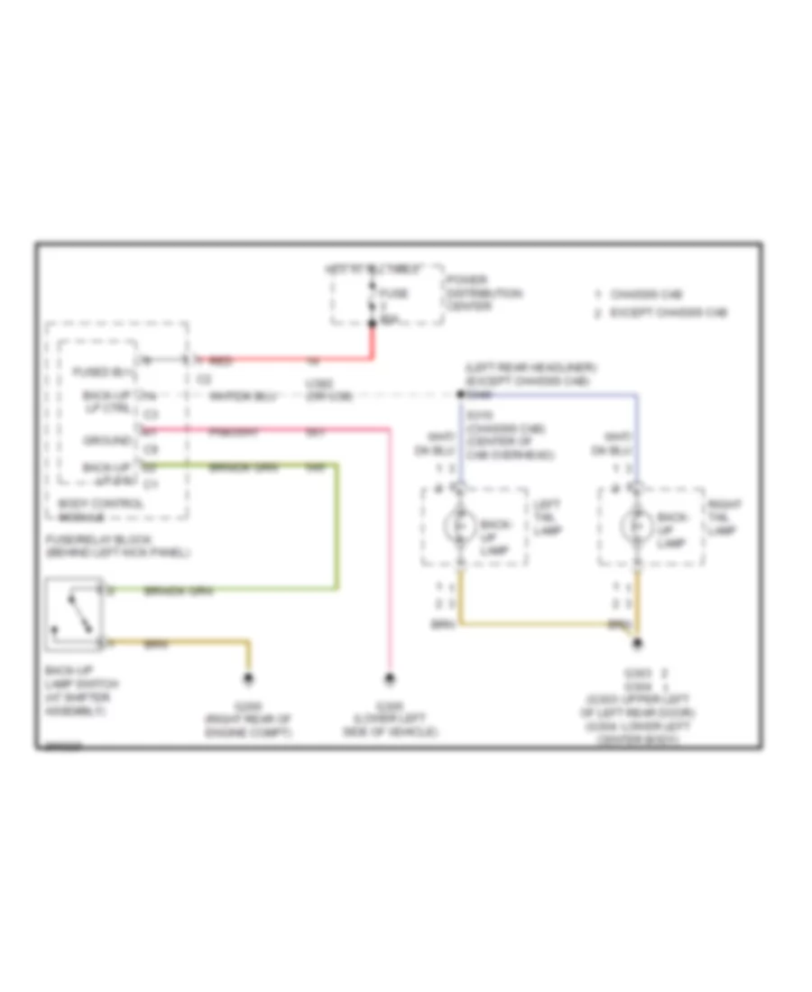
Back-up Lamps Wiring Diagram for Dodge Sprinter 2007 3500
 https://portal-diagnostov.com/license.html
Automotive Electricians Portal FZCO
Automotive Electricians Portal FZCO
https://portal-diagnostov.com/license.html
https://portal-diagnostov.com/license.html
Automotive Electricians Portal FZCO
Automotive Electricians Portal FZCOList of elements for Back-up Lamps Wiring Diagram for Dodge Sprinter 2007 3500:
- (left rear headliner) (except chassis cab) s340
- Back- up lamp
- Back-up
- Back-up lamp switch (at shifter assembly)
- Body control module
- Chassis cab
- Except chassis cab
- Fuse 80a
- Fuse/relay block (behind left kick panel)
- Fused b(+)
- G200 (right rear of engine compt)
- G303 g304 (g303: upper left of left rear door) (g304: lower left center body)
- G305 (lower left side of vehicle)
- Ground
- Hot at all times
- Left tail lamp
- Lp ctrl c3
- Lp sw c1
- Power distribution center
- Red
- Right tail lamp
- U382 (or u38)
Exterior Lamps Wiring Diagram (1 of 2) for Dodge Sprinter 2007 3500
 https://portal-diagnostov.com/license.html
Automotive Electricians Portal FZCO
Automotive Electricians Portal FZCO
https://portal-diagnostov.com/license.html
https://portal-diagnostov.com/license.html
Automotive Electricians Portal FZCO
Automotive Electricians Portal FZCOList of elements for Exterior Lamps Wiring Diagram (1 of 2) for Dodge Sprinter 2007 3500:
- (except chassis cab) (chassis cab)
- (in engine compt) anti-lock brakes module
- (in engine compt) stop lamp switch
- (or 2330)
- (or 2331)
- (or 2334)
- (or 2335)
- (or 2336)
- (or 2337)
- (or 3593)
- (or 3595)
- (or 3603)
- (or 3605)
- (or u3011)
- (or u3012)
- (or u3013)
- (or u3014)
- (or u94)
- (rear of vehicle) trailer tow lighting module
- Additional turn signal lamps
- Base
- Body control module
- Brake light
- Can b bus (+)
- Can b bus (-)
- Center front identification lamp
- Chassis cab
- Cluster
- Computer data lines system
- Except additional
- Except base
- Except chassis cab
- Except trailer tow
- Fuse 7.5a
- Fuse/ relay block (behind left kick panel)
- Fused b (+)
- G102 (right front of engine compt)
- G103 (left rear of engine compt)
- G300 (left front headliner)
- G303 (except chassis cab) (upper left of left rear door)
- G303 (upper left of left rear door)
- G304 (chassis cab) (lower left center body)
- G305 (lower left side of vehicle)
- Ground
- High mount stop
- Hot at all times
- Hot w/ terminal 15 relay energized
- Left front identification lamp
- Left headlamp lamp
- Left license lamp
- Left turn
- Lf turn sig
- Lh parking lps
- Lh stop lp ctrl
- License lps ctrl
- Lr park lp ctrl
- Lr turn sig ctrl
- Park
- Red
- Rf turn sig
- Rh parking lps
- Rh stop lp ctrl
- Right front identification lamp
- Right headlamp lamp
- Right license lamp
- Right tail lamp
- Right turn
- Rr park lp ctrl
- Rr turn sig ctrl
- S303 (left rear engine compt)
- S329
- S344 s312 (except chassis cab: left rear headliner) (chassis cab: left rear engine compt)
- S350 (on overhead (dls) harness)
- Stop
- Stop lp sw out
- Sw out
- Sw out nc
- Tail stop 3 lamp
- Trailer tow
- Turn sig ctrl
- Turn signal lamps
- Upfitters connector (x145/6)
Exterior Lamps Wiring Diagram (2 of 2) for Dodge Sprinter 2007 3500
 https://portal-diagnostov.com/license.html
Automotive Electricians Portal FZCO
Automotive Electricians Portal FZCO
https://portal-diagnostov.com/license.html
https://portal-diagnostov.com/license.html
Automotive Electricians Portal FZCO
Automotive Electricians Portal FZCOList of elements for Exterior Lamps Wiring Diagram (2 of 2) for Dodge Sprinter 2007 3500:
- (except chassis cab) (chassis cab)
- (or u3013)
- (or u3014)
- Additional turn signal control module (under driver's seat)
- Additional turn signal lamps
- Can b bus (+)
- Can b bus (-)
- Can c bus (+)
- Can c bus (-)
- Chassis cab
- Computer data lines system
- Diagnostic junction block 25
- Except additional
- Except chassis cab
- Fuse 10a
- Fuse 80a
- Fuse block 4
- Fused b (+)
- G200 (right rear of engine compt)
- G301 (lower left side of vehicle)
- G303 (except chassis cab) (upper left of left rear door)
- G304 (chassis cab) (lower left center body)
- G304 (lower left center body)
- Ground
- Hazard switch
- Hot at all times
- Ignition switch
- Left tail lamp
- Left turn
- Lh turn sig ctrl
- Lr turn sig ctrl
- Lss direction ind left/right
- Lss headlamp flasher/high beam
- Park
- Power distribution center
- Red
- Rh turn sig ctrl
- Rr turn sig ctrl
- S330 s311 (except chassis cab: left rear headliner) (chassis cab: left rear engine compt)
- Steering control module (behind left side of instrument panel)
- Stop
- Switch bank module
- Turn sig ctrl
- Turn signal lamps
- Turn signal switches
- Upfitters connector (x52/10)
- Upfitters connector (x52/9)
Trailer Tow Wiring Diagram for Dodge Sprinter 2007 3500
 https://portal-diagnostov.com/license.html
Automotive Electricians Portal FZCO
Automotive Electricians Portal FZCO
https://portal-diagnostov.com/license.html
https://portal-diagnostov.com/license.html
Automotive Electricians Portal FZCO
Automotive Electricians Portal FZCOList of elements for Trailer Tow Wiring Diagram for Dodge Sprinter 2007 3500:
- (not used)
- (or 948)
- (or 949)
- Additional terminal 15 relay (in engine compartment)
- Body control module
- Brk in
- Brk out
- Can b bus (+)
- Can b bus (-)
- Computer data lines system
- Electric brake control module
- Ext dir ind
- Fuse 25a
- Fuse 7.5a
- Fuse block 3
- Fuse block 4
- Fuse block 6
- Fuse/relay block (behind left kick panel)
- Fused b(+)
- G301 (lower left side of vehicle)
- G304 (lower left center body)
- G305 (lower left side of vehicle)
- Gnd
- Hot at all times
- Lh dir ind
- Lh tail lmp
- Rev lmp
- Rh dir ind
- S303 (left rear engine compartment)
- S329 (left rear engine compartment)
- Stop lamp switch (in engine compartment)
- Term 54
- Trailer tow connector
- Trailer tow lighting module (rear of vehicle)
- U94
GROUND DISTRIBUTION
Ground Distribution Wiring Diagram (1 of 3) for Dodge Sprinter 2007 3500
 https://portal-diagnostov.com/license.html
Automotive Electricians Portal FZCO
Automotive Electricians Portal FZCO
https://portal-diagnostov.com/license.html
https://portal-diagnostov.com/license.html
Automotive Electricians Portal FZCO
Automotive Electricians Portal FZCOList of elements for Ground Distribution Wiring Diagram (1 of 3) for Dodge Sprinter 2007 3500:
- (3.0l) engine control module
- (3.5l) powertrain control module
- (except most) universal cellphone interface
- 3.5l
- Adaptive lighting module
- Antenna booster assembly
- Anti-lock brakes module
- Auxiliary battery
- Auxiliary drive on switch
- Auxiliary fan relay
- Backup lamp switch
- Battery
- Battery isolation switch
- Blend door 2 actuator
- Blower motor
- Blower motor regulator
- Body control module
- Cd changer
- Center blend door actuator
- Cigar lighter
- Cluster
- Diagnostic junction block 25
- Front power outlet
- Front wiper motor
- Fuse/relay block
- G100 (left rear of engine compt)
- G101 (left rear of engine compt)
- G102 (right front of engine compt)
- G103 (left rear of engine compt)
- G106 (3.5l) (left front of engine compt)
- G200 (right rear of engine compt)
- G201 (front center headliner)
- Glove box lamp
- Headlamp leveling switch
- Heater a/c control
- Heater ptc
- Ignition coil 1
- Ignition coil 2
- Ignition coil 3
- Ignition coil 4
- Ignition coil 5
- Ignition coil 6
- Ignition switch
- Left headlamp
- Left ignition capacitor
- Parking heater switch
- Parking heater warm water switch
- Passenger air bag
- Radio
- Radio signal receiver heater
- Rear camera
- Rear camera monitor
- Rear roof lamp switch
- Right front fog lamp
- Right headlamp
- Roof ventilator switch
- S104 (right side engine compt)
- S105 (left side engine compt)
- S212 (on front hvac unit)
- S224 (in instrument panel)
- S318 (upper left rear engine compt)
- S348 (left rear headliner)
- Shifter lever assembly
- Siren
- Speed control switch
- Steering column lock module
- Steering control module
- Switch bank module
- To g303 (diagram 3 of 3)
- Upfitters body electrical switch
Ground Distribution Wiring Diagram (2 of 3) for Dodge Sprinter 2007 3500
 https://portal-diagnostov.com/license.html
Automotive Electricians Portal FZCO
Automotive Electricians Portal FZCO
https://portal-diagnostov.com/license.html
https://portal-diagnostov.com/license.html
Automotive Electricians Portal FZCO
Automotive Electricians Portal FZCOList of elements for Ground Distribution Wiring Diagram (2 of 3) for Dodge Sprinter 2007 3500:
- (3.0l)
- (3.0l) glow plug module
- (3.5l)
- Additional turn signal control module
- Air pump flow sensor
- Anti-lock brakes module
- Auxiliary drive solenoid
- Battery isolator relay
- Body control module
- C328
- Center front identi- fication lamp
- Clutch pedal switch
- Data link connector
- Driver door module
- Driver seat belt switch
- Driver thorax air bag
- Dynamics sensor
- Electric air pump
- Electric heated windshield 1
- Electric heated windshield 2
- Front ceiling lamp & switch
- Fuel pump module
- G104 (left side of engine compt)
- G105 (3.5l) (right side of engine compt)
- G108 (right front of engine compt)
- G109 (left front of engine compt)
- G300 (left front headliner)
- G301 (lower left side of vehicle)
- G302 (left rear of engine compt)
- Headlamp washer motor
- Heated windshield relay
- Heater control valve
- Hood ajar switch
- Horn 1
- Ignition coil 1
- Ignition coil 2
- Ignition coil 3
- Intrusion sensor
- Intrusion sensor 1
- Intrusion sensor 2
- Intrusion sensor 3
- Left box seat power outlet
- Left front fog lamp
- Left front identification lamp
- Left side curtain air bag
- Park assist module
- Parking brake module
- Passenger entry lamp
- Passenger thorax air bag
- Progra- mmable special module
- Rear door washer pump
- Rear recirculation door actuator 2
- Relay block
- Right front identi- fication lamp
- Right ignition capacitor
- Right outside rearview mirror
- Roof auxiliary fan relay
- Roof blend door actuator 2
- Roof control module
- S351 (left center headliner)
- Stop auxiliary drive switch
- Terminal additional relay 15
- Tire pressure monitor module
- Upfitters connector x145/6
- Upfitters connector x178
- Windshield washer pump
Ground Distribution Wiring Diagram (3 of 3) for Dodge Sprinter 2007 3500
 https://portal-diagnostov.com/license.html
Automotive Electricians Portal FZCO
Automotive Electricians Portal FZCO
https://portal-diagnostov.com/license.html
https://portal-diagnostov.com/license.html
Automotive Electricians Portal FZCO
Automotive Electricians Portal FZCOList of elements for Ground Distribution Wiring Diagram (3 of 3) for Dodge Sprinter 2007 3500:
- (3.0l) transmission control module
- (chassis cab) left tail lamp
- (chassis cab) right tail lamp
- (except chassis cab) left tail lamp
- (except chassis cab) right tail lamp
- Blower vent relay
- Body control module
- Diagnostic junction block 27
- From s348 (diagram 1 of 3)
- G303 (upper left of left rear door)
- G304 (lower left center body)
- G305 (lower left side of vehicle)
- G306 (left rear of engine compt)
- G307 (right rear of engine compt)
- Heat auxiliary dosing pump
- Highline
- Left electric heated backlite
- Left license lamp
- Left rear door wiper motor
- Left rear power outlet
- Left side impact sensor 1
- Left side impact sensor 2
- Lowline
- Occupant restraint controller module
- Rear recirculation door actuator
- Rear window defogger relay 1
- Relay block
- Reverse horn
- Right electric heated backlite
- Right license lamp
- Right rear door wiper motor
- Right rear power outlet
- Right side curtain air bag
- Right side impact sensor 1
- Right side impact sensor 2
- Tail stop lamp 3
- Terminal relief relay 15
- Trailer tow lighting module
- Upfitters connector x52/10
- Upfitters connector x52/9
HEADLIGHTS
Adaptive Front Lighting Wiring Diagram for Dodge Sprinter 2007 3500
 https://portal-diagnostov.com/license.html
Automotive Electricians Portal FZCO
Automotive Electricians Portal FZCO
https://portal-diagnostov.com/license.html
https://portal-diagnostov.com/license.html
Automotive Electricians Portal FZCO
Automotive Electricians Portal FZCOList of elements for Adaptive Front Lighting Wiring Diagram for Dodge Sprinter 2007 3500:
- (right rear of engine compt) g200
- Adaptive lighting module
- Can c bus+
- Can c bus-
- Computer data lines system
- Front headlamp level sensor (front of vehicle)
- Frt headlamp lvl sig
- Fuse 5a
- Fuse/ relay block (behind left kick panel)
- G103 (left rear of engine compt)
- Ground
- Headlamp leveling ctrl mtr
- Headlamp leveling switch
- Hot w/ terminal 15 relay energized
- Ignition (run-acc)
- Left headlamp
- Rear headlamp level sensor (in engine compt)
- Right headlamp
- Rr headlamp lvl sig
- S316
- S317 (upper left rear engine compt)
- S318
- Sensor gnd
- U356
- U3612
- U6103
Headlamps Wiring Diagram for Dodge Sprinter 2007 3500
 https://portal-diagnostov.com/license.html
Automotive Electricians Portal FZCO
Automotive Electricians Portal FZCO
https://portal-diagnostov.com/license.html
https://portal-diagnostov.com/license.html
Automotive Electricians Portal FZCO
Automotive Electricians Portal FZCOList of elements for Headlamps Wiring Diagram for Dodge Sprinter 2007 3500:
- (or 3592)
- (or 3594)
- (or 3602)
- (or 3604)
- Body control module (in fuse/relay block)
- Can b bus +
- Can b bus -
- Computer data lines system
- Dimmer switch
- Except xenon
- Fog lamp
- Fuse 25a
- Fuse 5a
- Fuse block 5
- Fuse/ relay block (behind left kick panel)
- Fused b +
- Fused b+
- Fused term 15 rly out
- G102 (right front of engine compt)
- G103 (left rear of engine compt)
- G300 (left front headliner)
- Ground
- High beam
- Hot at all times
- Hot w/ terminal 15 relay energized
- Ignition switch
- Left front fog lamp
- Left headlamp high beam
- Left headlamp lamp
- Left headlamp low beam
- Low beam
- Lt sw bcd 1
- Lt sw bcd 2
- Lt sw bcd 3
- Lt sw gnd
- Lt sw term 31
- Lt/rain sens data
- Rain/light sensor (top center of windshield)
- Right front fog lamp
- Right headlamp high beam
- Right headlamp lamp
- Right headlamp low beam
- Roof control module (in roof console)
- Rotary lt sw al-redundant
- Rotary lt sw nswinsl
- Rotary lt sw redundant
- S202
- S221
- S323 (center of cab overhead)
- Sens ground
- Sens sply
- Term
- Term 15
- Term 15r
- U337
- Xenon
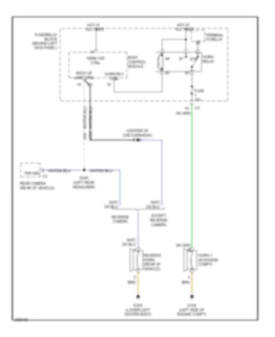
HORN
Horn Wiring Diagram for Dodge Sprinter 2007 3500
 https://portal-diagnostov.com/license.html
Automotive Electricians Portal FZCO
Automotive Electricians Portal FZCO
https://portal-diagnostov.com/license.html
https://portal-diagnostov.com/license.html
Automotive Electricians Portal FZCO
Automotive Electricians Portal FZCOList of elements for Horn Wiring Diagram for Dodge Sprinter 2007 3500:
- (center of cab overhead) s310
- 87a
- Back up lamp ctrl
- Body control module
- Except reverse camera
- Fuse 15a
- Fuse/relay block (behind left kick panel)
- G104 (left side of engine compt)
- G304 (lower left center body)
- Horn 1 (in engine compt)
- Horn relay
- Horn rly ctrl
- Hot at all times
- Rear camera (rear of vehicle)
- Reverse camera
- Reverse horn (rear of vehicle)
- S340 (left rear headliner)
- Ter 58d c3
- Term 15r ctrl
- Terminal 15 relay
- U38
- U382
INSTRUMENT CLUSTER
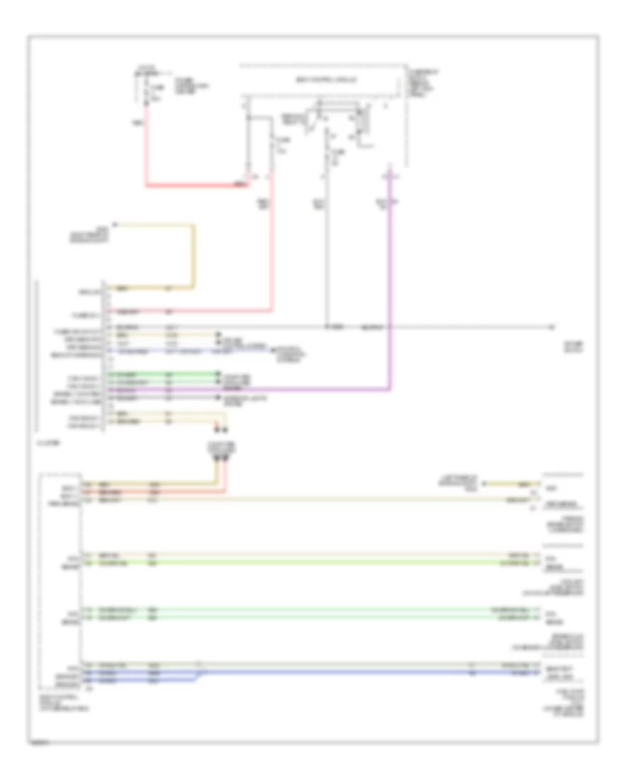
Instrument Cluster Wiring Diagram for Dodge Sprinter 2007 3500
 https://portal-diagnostov.com/license.html
Automotive Electricians Portal FZCO
Automotive Electricians Portal FZCO
https://portal-diagnostov.com/license.html
https://portal-diagnostov.com/license.html
Automotive Electricians Portal FZCO
Automotive Electricians Portal FZCOList of elements for Instrument Cluster Wiring Diagram for Dodge Sprinter 2007 3500:
- (left rear of engine compt) g302
- (or 4321)
- (or u61)
- Backup camera sig
- Body control module
- Body control module (in fuse/relay box)
- Brake fluid level switch (on brake fluid reservoir)
- Brake lt sw close
- Brake lt sw open
- Bus (+)
- Bus (-)
- Can b bus (+)
- Can b bus (-)
- Can c bus (+)
- Can c bus (-)
- Cluster
- Computer data lines system
- Coolant level switch (in coolant reservoir)
- Cruise control system
- Dimmer switch
- Exterior lights system
- Fuel pump module (3.0l) (under center of vehicle)
- Fuse 10a
- Fuse 5a
- Fuse 80a
- Fuse/relay block (behind left kick panel)
- Fused b (+)
- Fused ign sw out
- G200 (right rear of engine compt)
- Gnd
- Ground
- Hot at all times
- Level gnd
- Park brake
- Parking brake switch (under dash)
- Power distribution center
- Red
- Rtn
- S202
- Sens sig
- Sens text
- Sense
- Sound & navigation systems
- Spd sens rtn
- Spd sens sig
- Terminal relay 15
- U311
INTERIOR LIGHTS
Courtesy Lamps Wiring Diagram (1 of 2) for Dodge Sprinter 2007 3500
 https://portal-diagnostov.com/license.html
Automotive Electricians Portal FZCO
Automotive Electricians Portal FZCO
https://portal-diagnostov.com/license.html
https://portal-diagnostov.com/license.html
Automotive Electricians Portal FZCO
Automotive Electricians Portal FZCOList of elements for Courtesy Lamps Wiring Diagram (1 of 2) for Dodge Sprinter 2007 3500:
- (premium lighting)
- (right rear of engine compt) g200
- Base lighting
- Body control module
- Can b bus(+)
- Can b bus(-)
- Computer data lines system
- Dimmer switch
- Driver door module
- Driver entry lamp
- Drv entry/exit lp drv
- Frt interior lamp
- Fuse 150a
- Fuse 15a
- Fuse 30a
- Fuse 5a
- Fuse block 2 (top of fuse/ relay block)
- Fuse/ relay block (behind left kick panel)
- Fuse/relay block (behind left kick panel)
- Fused b(+)
- Fused ig sw out
- G200 (right rear of engine compt)
- G302 (left rear of engine compt)
- Glove box lamp
- Gnd
- Hot at all times
- Hot w/ terminal 15 relay energized
- Hot w/ terminal 15r relay energized
- Interior lamp 1 sw
- Interior lamp term 30
- Lt sw bcd1
- Lt sw bcd2
- Lt sw bcd3
- Lt sw term 31
- Movement sens out
- Pass entry/exit lp drv
- Passenger entry lamp
- Power distribution center
- Premium lighting
- Rear load area lamp
- Rear roof lamp switch
- Red
- Rot lt sw al-redundant
- Rotary lt sw nsw/nsl
- Rr interior lamp
- S200
- S202
- S203
- S221
- S301
- Term 58d
- U1036
- U41
- U774
- U815
Courtesy Lamps Wiring Diagram (2 of 2) for Dodge Sprinter 2007 3500
 https://portal-diagnostov.com/license.html
Automotive Electricians Portal FZCO
Automotive Electricians Portal FZCO
https://portal-diagnostov.com/license.html
https://portal-diagnostov.com/license.html
Automotive Electricians Portal FZCO
Automotive Electricians Portal FZCOList of elements for Courtesy Lamps Wiring Diagram (2 of 2) for Dodge Sprinter 2007 3500:
- (center of cab overhead) s320
- Base lighting
- Dr ajar sw
- Drv int lp 1
- Drv int lp 2
- Front ceiling lamp & switch (premium lighting)
- Frt int lp
- Fused b(+)
- G300 (left front headliner)
- G305 (lower left side of vehicle)
- Gnd
- Illumination relay
- Left load area 1 lamp
- Left rear entry lamp
- Premium lighting
- Rear ceiling 1 lamp & switch (premium lighting)
- Rear ceiling 2 lamp & switch (premium lighting)
- Rear ceiling 2 lamp (premium lighting)
- Rear ceiling 3 lamp & switch (premium lighting)
- Rear ceiling 3 lamp (premium lighting)
- Rear ceiling 4 lamp (premium lighting)
- Rear ceiling lamp
- Red
- Red (center of cab overhead) s319
- Relay block
- Right load area 1 lamp
- Right load area 2 lamp
- Right rear entry lamp
- Rr int lp
- S341 (left rear headliner)
- S342 (left front headliner)
- S346 (left center headliner)
- Working 1 lamp
- Working 2 lamp
NAVIGATION
Parking Assistant Wiring Diagram (1 of 2) for Dodge Sprinter 2007 3500
 https://portal-diagnostov.com/license.html
Automotive Electricians Portal FZCO
Automotive Electricians Portal FZCO
https://portal-diagnostov.com/license.html
https://portal-diagnostov.com/license.html
Automotive Electricians Portal FZCO
Automotive Electricians Portal FZCOList of elements for Parking Assistant Wiring Diagram (1 of 2) for Dodge Sprinter 2007 3500:
- (center of cab overhead) s325
- (center of cab overhead) s326
- (lower left side of vehicle) g301
- (under driver's seat) park assist module
- Can b bus (+)
- Can b bus (-)
- Computer data lines system
- Front park assist display
- Front prk assist 1 sig
- Front prk assist 2 sig
- Front prk assist 3 sig
- Front prk assist 4 sig
- Front prk assist 5 sig
- Front prk assist 6 sig
- Front prk assist display gnd
- Front prk assist display sig
- Front prk assist display sply
- Front prk assist sens gnd
- Front prk assist sens sply
- Fuse 7.5a
- Fuse block 4
- Fused b(+)
- Gnd
- Hot at all times
- Left outside rearview mirror
- Park assist sensor 10 (in rear bumper)
- Park assist sensor 8 (in rear bumper)
- Park assist sensor 9 (in rear bumper)
- Rear park assist display
- Rear prk assist display gnd
- Rear prk assist display gnd c2
- Rear prk assist display sig
- Rear prk assist display sply
- Rear prk assist display sply c2
- Rear prk assist sens 10 sig
- Rear prk assist sens 7 sig
- Rear prk assist sens 8 sig
- Rear prk assist sens 9 sig
- Rear prk assist sens gnd
- Rear prk assist sens sply
- Right outside rearview mirror
- Rr prk assist display sply
- S324
- S369 (rear bumper)
- S370 (rear bumper)
- Sens 10 sig
- Sens 8 sig
- Sens 9 sig
- Sens sply
- U3622
- U3623
- U3624
Parking Assistant Wiring Diagram (2 of 2) for Dodge Sprinter 2007 3500
 https://portal-diagnostov.com/license.html
Automotive Electricians Portal FZCO
Automotive Electricians Portal FZCO
https://portal-diagnostov.com/license.html
https://portal-diagnostov.com/license.html
Automotive Electricians Portal FZCO
Automotive Electricians Portal FZCOList of elements for Parking Assistant Wiring Diagram (2 of 2) for Dodge Sprinter 2007 3500:
- (in front fascia) park assist sensor 1
- (in front fascia) park assist sensor 2
- (in front fascia) park assist sensor 3
- (in front fascia) park assist sensor 5
- (lower left front fascia) s371
- (lower left front fascia) s372
- Park assist sensor 4 (in front fascia)
- Park assist sensor 6 (in front fascia)
- Park assist sensor 7 (in rear bumper)
- Prk assist
- Prk assist sens 6 sig
- Prk assist sens gnd
- Prk assist sens sply
- Sens 1 sig prk assist
- Sens 2 sig prk assist
- Sens 3 sig prk assist
- Sens 4 sig
- Sens 5 sig prk assist
- Sens 7 sig
- Sens gnd
- Sens gnd prk assist
- Sens sply
- Sens sply prk assist
Rear Camera Wiring Diagram, with Monitor Preinstallation for Dodge Sprinter 2007 3500
 https://portal-diagnostov.com/license.html
Automotive Electricians Portal FZCO
Automotive Electricians Portal FZCO
https://portal-diagnostov.com/license.html
https://portal-diagnostov.com/license.html
Automotive Electricians Portal FZCO
Automotive Electricians Portal FZCOList of elements for Rear Camera Wiring Diagram, with Monitor Preinstallation for Dodge Sprinter 2007 3500:
- (center of cab overhead) s310
- (instrument panel) s223
- Back-up
- Back-up camera
- Back-up camera antenna
- Back-up camera connector
- Back-up lamps ctrl
- Back-up lamps ctrl c3
- Back-up lamps ctrl right taillamp (chassis cab)
- Body control module (in fuse/relay block)
- C10
- Chassis cab
- Except back-up camera
- Except chassis cab
- Except rear camera
- Except rear camera provision
- Fuse 10 15a
- Fuse 3 5a
- Fuse block 2 (top of fuse/relay box)
- Fuse block 3
- G200 (right rear of engine compt)
- G301 (lower left side of vehicle)
- G304 (lower left center body)
- Hot at all times
- Hot w/ additional terminal 15 relay energized
- Lamps ctrl left taillamp (chassis cab)
- Left taillamp (except chassis cab)
- Nca
- Pnk
- Radio
- Rear camera
- Rear camera (rear of vehicle)
- Rear camera provision
- Reverse horn (rear of vehicle)
- Right taillamp (except chassis cab)
- S322
- S340 (left rear headliner)
- S348
- U38 (or u382)
Rear Camera Wiring Diagram, without Monitor Preinstallation for Dodge Sprinter 2007 3500
 https://portal-diagnostov.com/license.html
Automotive Electricians Portal FZCO
Automotive Electricians Portal FZCO
https://portal-diagnostov.com/license.html
https://portal-diagnostov.com/license.html
Automotive Electricians Portal FZCO
Automotive Electricians Portal FZCOList of elements for Rear Camera Wiring Diagram, without Monitor Preinstallation for Dodge Sprinter 2007 3500:
- (center of cab overhead) s310
- Back-up
- Back-up camera antenna
- Back-up camera connector
- Back-up lamps ctrl
- Back-up lamps ctrl c3
- Back-up lamps ctrl right taillamp (chassis cab)
- Body control module (in fuse/relay block)
- Chassis cab
- Except chassis cab
- Except rear camera
- Except rear camera provision
- Fuse 3 5a
- Fuse block 3
- G200 (right rear of engine compt)
- G301 (lower left side of vehicle)
- G304 (lower left center body)
- Hot w/ additional terminal 15 relay energized
- Lamps ctrl left taillamp (chassis cab)
- Left taillamp (except chassis cab)
- Nca
- Pnk
- Rear camera
- Rear camera (rear of vehicle)
- Rear camera provision
- Reverse horn (rear of vehicle)
- Right taillamp (except chassis cab)
- S224
- S322
- S340 (left rear headliner)
- To rear camera monitor
- U38 (or u382)
POWER DISTRIBUTION
Power Distribution Wiring Diagram (1 of 5) for Dodge Sprinter 2007 3500
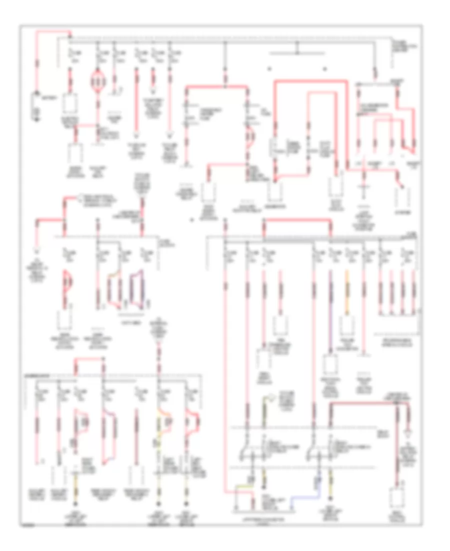 https://portal-diagnostov.com/license.html
Automotive Electricians Portal FZCO
Automotive Electricians Portal FZCO
https://portal-diagnostov.com/license.html
https://portal-diagnostov.com/license.html
Automotive Electricians Portal FZCO
Automotive Electricians Portal FZCOList of elements for Power Distribution Wiring Diagram (1 of 5) for Dodge Sprinter 2007 3500:
- (center of cab overhead) s313
- (center of cab overhead) s314
- (not used)
- (on generator harness) s117
- 100a
- 300a
- 30a
- 50a
- A/c fuse
- Additional turn signal control module
- Auxiliary fan relay
- Auxiliary heater 1 module
- Auxiliary heater 2 module
- Auxiliary roof fan relay
- B red
- Battery
- Blend door 1 actuator
- Body control module
- Body manufacturer 15 relay
- Body manufacturer d+ relay
- C329
- C340
- Electric air pump relay
- Except lt3
- From additional terminal 15 relay (diagram 2 of 5)
- Fuse 10a
- Fuse 150a
- Fuse 15a
- Fuse 20a
- Fuse 25a
- Fuse 30a
- Fuse 7.5a
- Fuse 80a
- Fuse block 4
- Fuse block 5
- Fuse block 6
- G301 (lower left side of vehicle)
- G303 (upper left of left rear door)
- Gene- rator fuse
- Generator
- Glow plug module
- Glow plug module fuse
- Heated windshield relay
- Heater ptc
- Jump starting point connector (positive)
- Left box seat power outlet
- Left rear power outlet
- Lt3
- Nca
- Park assist module
- Power distribution center
- Programmable special module
- Rear recirculation door 1 actuator
- Rear recirculation door 2 actuator
- Rear window defogger 1 relay
- Rear window defogger 2 relay
- Red
- Relay block
- Right rear power outlet
- Roof blend door 1 actuator
- S211 (on front hvac unit) red
- S352 (left center headliner)
- Starter
- Tire pressure monitor module
- To battery isolator relay (diagram 3 of 5)
- To external fuse 1 (diagram 3 of 5)
- To fuse block 3 (fuse 8) (diagram 4 of 5)
- To fuse block 5 (fuse 19) (diagram 3 of 5)
- To fuse/ relay block (diagram 3 of 5)
- To relief terminal 15 relay (diagram 3 of 5)
- To splice s301 (diagram 2 of 5)
- Trailer tow connector
- Trailer tow lighting module
- Upfitters connector (x145/1)
- Windshield heater fuse
Power Distribution Wiring Diagram (2 of 5) for Dodge Sprinter 2007 3500
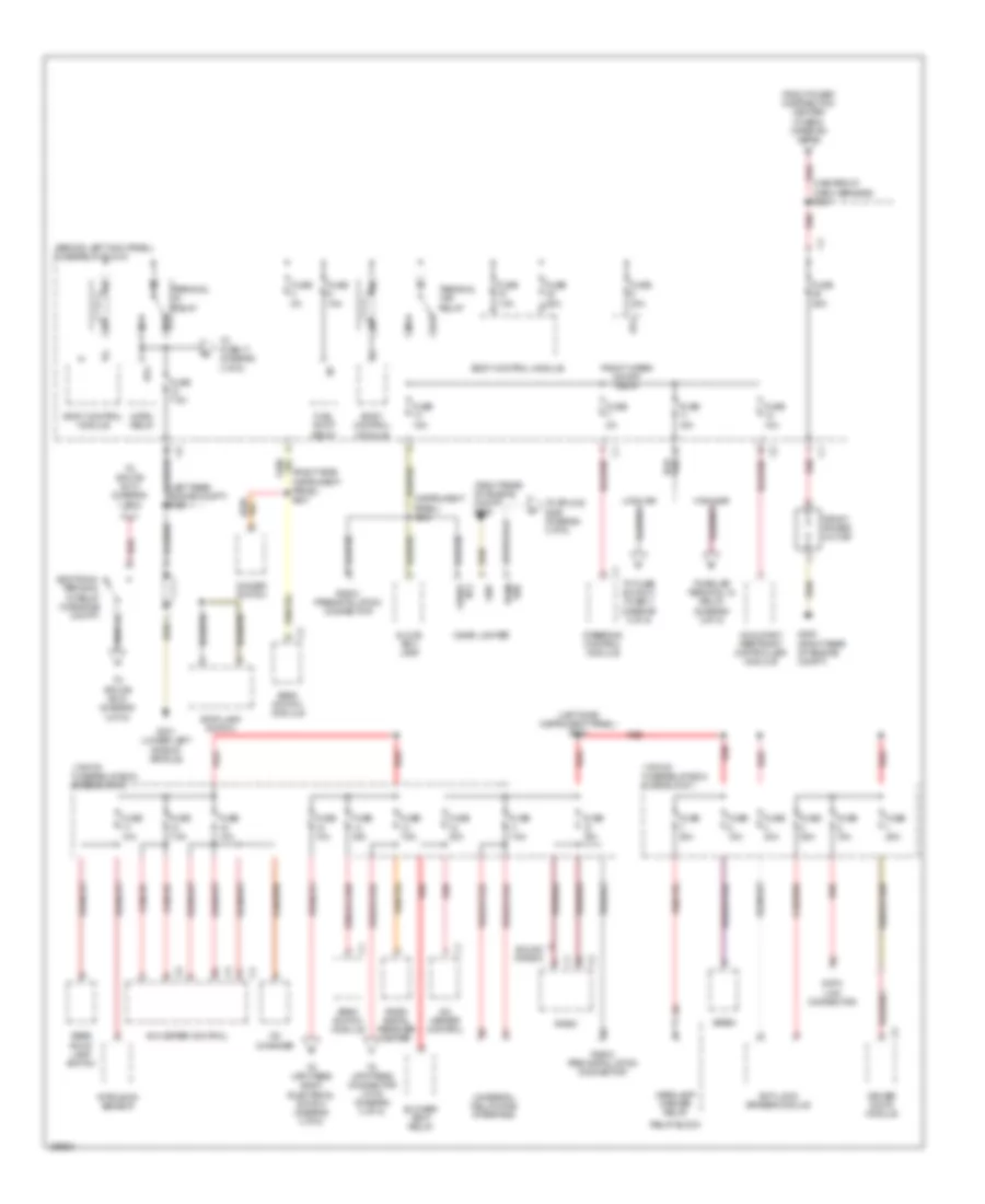 https://portal-diagnostov.com/license.html
Automotive Electricians Portal FZCO
Automotive Electricians Portal FZCO
https://portal-diagnostov.com/license.html
https://portal-diagnostov.com/license.html
Automotive Electricians Portal FZCO
Automotive Electricians Portal FZCOList of elements for Power Distribution Wiring Diagram (2 of 5) for Dodge Sprinter 2007 3500:
- (behind left kick panel) fuse/relay block
- (center of cab overhead) s301
- (left rear engine compt) s329
- (left side instrument panel) s222
- (right rear of engine compt) g200
- (right side instrument panel) s221
- (top of fuse/relay box) fuse block 1
- (top of fuse/relay box) fuse block 2
- 58d
- 87a
- A/c heater control
- Additional terminal 15 relay (in engine compt)
- Anti-lock brakes module
- Bank switch module
- Blower vent relay
- Body control module
- Cd changer
- Cigar lighter
- Data link connector
- Dimmer switch
- Driver door module
- From power distribution center (fuse 5) (diagram 1 of 5)
- Front power outlet
- Front wiper on/off relay
- Fuel pump relay
- Fuse 10a
- Fuse 15a
- Fuse 25a
- Fuse 30a
- Fuse 40a
- Fuse 5a
- Fuse 7.5a
- Fused b(+)
- G200 (right rear of engine compt)
- G301 (lower left side of vehicle)
- Glove box lamp
- Gnd
- Headlamp washer relay
- Highline
- Horn relay
- Intrusion sensor
- Lowline
- Occupant restraint controller module
- Panel) s203
- Radio
- Radio pre-installation connector
- Radio preinstallation connector
- Radio signal receiver heater
- Rear roof lamp switch
- Red
- Relay block
- Siren
- Sound 5 radio
- Steering control module
- Stop lamp switch
- Term
- Terminal 15r relay
- Terminal relay
- To fuse 17 (diagram 4 of 5)
- To fuse block 3 (fuse 1) (diagram 3 of 5)
- To relief terminal 15 relay (diagram 3 of 5)
- To splice s200 (diagram 4 of 5)
- To splice s314 (diagram 1 of 5)
- To splice s315 (diagram 4 of 5)
- To upfitters body electrical switch (diagram 4 of 5)
- To upfitters connector (x178) (diagram 4 of 5)
- Universal cellphone interface
Power Distribution Wiring Diagram (3 of 5) for Dodge Sprinter 2007 3500
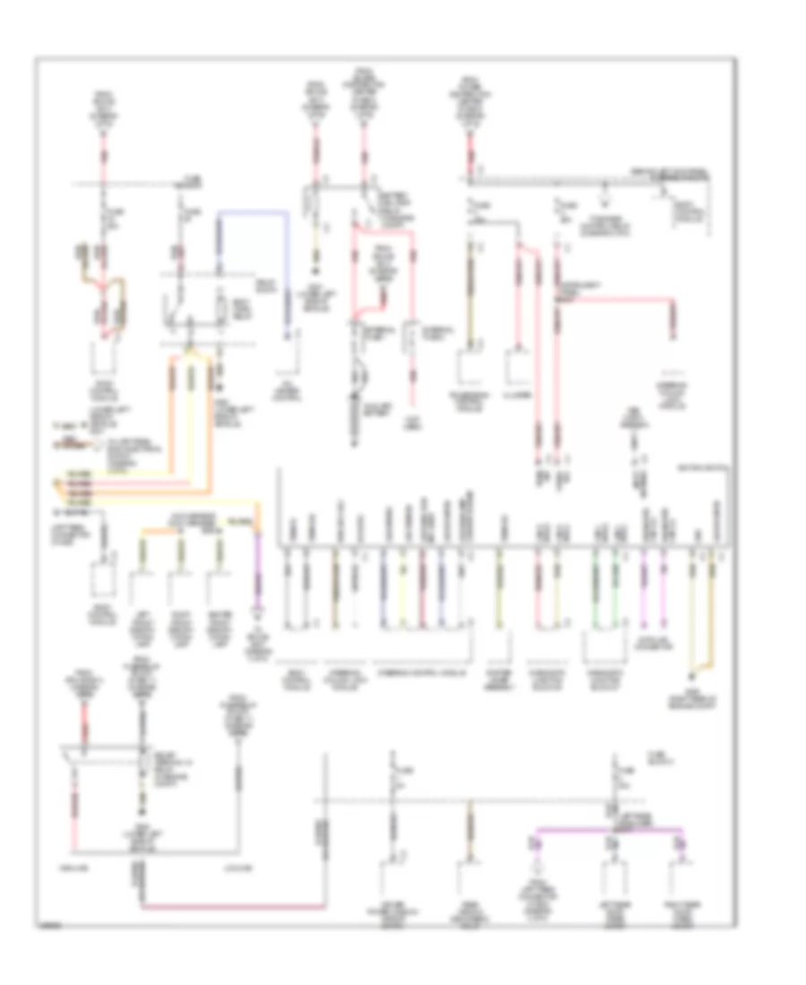 https://portal-diagnostov.com/license.html
Automotive Electricians Portal FZCO
Automotive Electricians Portal FZCO
https://portal-diagnostov.com/license.html
https://portal-diagnostov.com/license.html
Automotive Electricians Portal FZCO
Automotive Electricians Portal FZCOList of elements for Power Distribution Wiring Diagram (3 of 5) for Dodge Sprinter 2007 3500:
- (behind left kick panel) fuse/relay block
- (instrument panel) s210
- (left rear headliner) s347
- (lower left side of vehicle) g301
- (not used)
- (on overhead (dls) harness) s350
- 30z term
- A/c heater control
- Antenna input
- Auxiliary battery
- B(+) fused
- Battery isolator relay (in engine compt)
- Body control module
- Body horn relay
- Bus(+) can b
- Bus(+) can c
- Bus(-) can b
- Can c bus(-)
- Center front identifi- cation lamp
- Cluster
- Data link connector
- Diagnostic can c(+)
- Diagnostic can c(-)
- Diagnostic junction block 25
- Diagnostic junction block 27
- Driver power window/ mirror switch
- Elv data
- External fuse 1
- External fuse 2
- Fbs hatch antenna
- Flasher hi beam lss headlamp
- From fuse/relay block (fuse 11) (diagram 2 of 5)
- From power distribution center (fuse 3) (diagram 1 of 5)
- From power distribution center (fuse 4) (diagram 1 of 5)
- From splice s313 (diagram 1 of 5)
- From splice s314 (diagram 1 of 5)
- From upfitters connector (x145/6) (diagram 3 of 5)
- Fuse
- Fuse 10a
- Fuse 25a
- Fuse 30a
- Fuse 5a
- Fuse block 3
- Fuse block 5
- G200 (right rear of engine compt)
- G301 (lower left side of vehicle)
- G305 (lower left side of vehicle)
- Gnd
- Highline
- Ignition switch
- Ind lh/rh lss direction
- Left front identifi- cation lamp
- Left rear door wiper motor
- Lowline
- Lss rr wiper
- Lss term 86
- Lss wipers
- M red
- Powertrain control module
- Pwr sply elv
- Rear window defogger 2 relay
- Red
- Relay block
- Relief terminal 15 relay (in engine compt)
- Right front identifi- cation lamp
- Right rear door wiper motor
- Roof control module
- Shifter lever assembly
- Steering column lock module
- Steering control module
- Term 15
- Term 15c
- Term 15r
- To engine control relay (diagram 5 of 5)
- To splice s347 (diagram 3 of 5)
- To upfitters body electrical switch (diagram 4 of 5)
- Upfitters connector (x145/6)
Power Distribution Wiring Diagram (4 of 5) for Dodge Sprinter 2007 3500
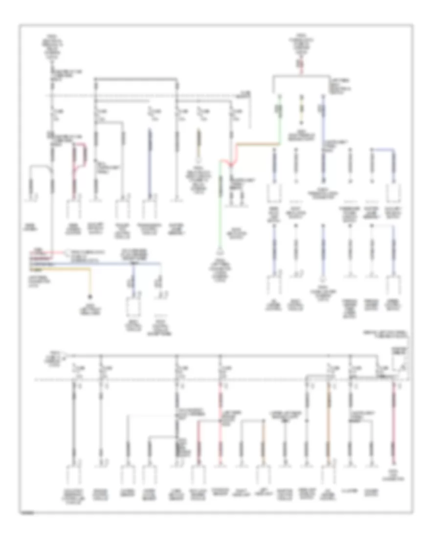 https://portal-diagnostov.com/license.html
Automotive Electricians Portal FZCO
Automotive Electricians Portal FZCO
https://portal-diagnostov.com/license.html
https://portal-diagnostov.com/license.html
Automotive Electricians Portal FZCO
Automotive Electricians Portal FZCOList of elements for Power Distribution Wiring Diagram (4 of 5) for Dodge Sprinter 2007 3500:
- (behind left kick panel) fuse/relay block
- (center of cab overhead) s315
- (center of cab overhead) s322
- (except base)
- (instrument panel) s200
- (instrument panel) s202
- (left rear engine compt) s328
- (on main body (hls) harness) s327
- (on overhead (dls) harness) (except base) s345
- (upper left rear engine compt) s316
- A/c heater control
- Adaptive lighting module
- Anti-lock brakes module
- Auxiliary drive on switch
- Body control module
- Cluster
- Data link connector
- Dimmer switch
- Dynamics sensor
- Engine control module
- From additional terminal 15 relay (diagram 2 of 5)
- From cigar lighter (diagram 2 of 5)
- From fuse 18 q (diagram 2 of 5)
- From fuse block 2 (fuse 13) (diagram 2 of 5)
- From fuse block 2 (fuse 15) (diagram 2 of 5)
- From relay block (body manufa- cturer 15 relay) (diagram 1 of 5)
- From upfitters connector (x145/6) (diagram 3 of 5)
- Fuse 10a
- Fuse 15a
- Fuse 25a
- Fuse 5a
- Fuse 7.5a
- Fuse block 3
- G200 (right rear of engine compt)
- G300 (left front headliner)
- Headlamp leveling switch
- Left headlamp
- Mass air flow sensor
- Occupant restraint controller module
- Oxygen sensor
- Parking heater switch
- Parking heater warm water switch
- Passenger power window switch
- Radio preinstallation connector
- Rear camera
- Rear camera monitor
- Rear roof lamp switch
- Right headlamp
- Roof control module
- Roof ventilator switch
- S214 (instrument panel)
- Shifter lever assembly
- Side engine compt)
- Speed control switch
- Starter relay
- Trailer tow lighting module
- Transmission control module
- Upfitters body electrical switch
- Upfitters connector (x178)
- Water in fuel sensor
Power Distribution Wiring Diagram (5 of 5) for Dodge Sprinter 2007 3500
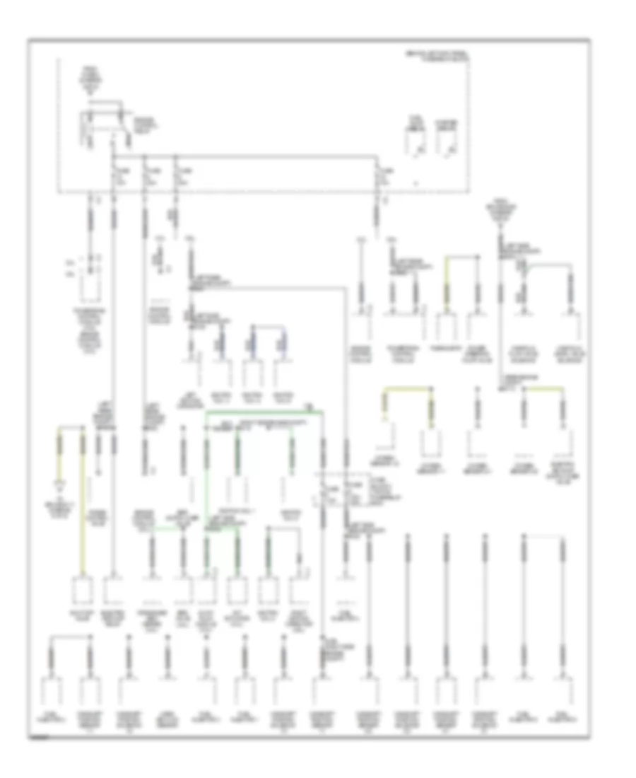 https://portal-diagnostov.com/license.html
Automotive Electricians Portal FZCO
Automotive Electricians Portal FZCO
https://portal-diagnostov.com/license.html
https://portal-diagnostov.com/license.html
Automotive Electricians Portal FZCO
Automotive Electricians Portal FZCOList of elements for Power Distribution Wiring Diagram (5 of 5) for Dodge Sprinter 2007 3500:
- (behind left kick panel) fuse/relay block
- (left rear engine compt) s302
- (left rear engine compt) s306
- (left rear engine compt) s321
- (left side engine compt) s102
- (left side engine compt) s108
- (left side engine compt) s111
- (rear engine compt) s112
- (right side engine compt) s110
- 3.0l
- 3.5l
- 87a
- Camshaft position sensor 1/1
- Camshaft position sensor 2/1
- Camshaft position sensor 2/2
- Camshaft position solenoid 1/2
- Camshaft position solenoid 2/1
- Camshaft position solenoid 2/2
- Crankcase vent heater (3.0l)
- Egr switch over valve
- Egr valve (3.0l)
- Electric air pump relay
- Electric air pump switch over valve
- Engine control module
- Engine control module (3.0l)
- Engine control relay
- From fuse 2 (diagram 3 of 5)
- From splice s306 (diagram 5 of 5)
- Fuel injector 1
- Fuel injector 2
- Fuel injector 3
- Fuel injector 4
- Fuel injector 5
- Fuel injector 6
- Fuel pump relay
- Fuse (3.5l) 7.5a
- Fuse 10a
- Fuse 20a
- Fuse 7.5a
- Fuse block 1 (top of fuse/relay box)
- Glow plug module (3.0l)
- Ignition coil 1
- Ignition coil 2
- Ignition coil 3
- Ignition coil 4
- Ignition coil 5
- Ignition coil 6
- Left ignition capacitor
- Manifold flow valve solenoid
- Manifold swirl valve solenoid
- Mass air flow sensor
- Oxygen sensor 1/1
- Oxygen sensor 1/2
- Oxygen sensor 2/1
- Oxygen sensor 2/2
- Power steering pump valve
- Powertrain control module
- Powertrain control module (3.5l) engine control module (3.0l)
- Purge control valve
- Right ignition capacitor (3.5l)
- S106 (right side engine compt)
- Shut-off valve
- Starter relay
- Thermostat
- To splice s111 (diagram 5 of 5)
- Vnt actuator (3.0l)
POWER DOOR LOCKS
Power Door Locks Wiring Diagram for Dodge Sprinter 2007 3500
 https://portal-diagnostov.com/license.html
Automotive Electricians Portal FZCO
Automotive Electricians Portal FZCO
https://portal-diagnostov.com/license.html
https://portal-diagnostov.com/license.html
Automotive Electricians Portal FZCO
Automotive Electricians Portal FZCOList of elements for Power Door Locks Wiring Diagram for Dodge Sprinter 2007 3500:
- (center of cab overhead) s307
- (center of cab overhead) s308
- (driver door) s353
- (passenger door) s354
- (right rear cargo door) s364
- (right sliding door) s356
- Body control module (in fuse/relay block)
- Can b bus (+)
- Can b bus (-)
- Child safety locks
- Diagnostic junction block 24
- Diagnostic junction block 25
- Door lock switch
- Driver door latch (left front door)
- Driver door module
- Driver power window/
- Drv dr ajar sw sns
- Drv dr lk drv
- Drv dr unlk drv
- Fuse 25a
- Fuse block 1 (top of fuse/relay box)
- Fused b (+)
- G301 (lower left side of vehicle)
- Gnd
- Hot at all times
- L dr latch position 1 sns
- L dr latch position 2 sns
- L sliding dr ajar sw sns
- Left rear door latch
- Left sliding door latch (left sliding door)
- Mirror switch
- Pass dr latch position sns
- Pass dr lk drv
- Pass dr unlk drv
- Passenger door latch (right front door)
- R sliding door ajar sw sns
- R sliding dr lk position sns
- R vent widw sw mux
- Rear door latch (in rear door)
- Rear dr ajar sw sns
- Rear dr lk position sns
- Rear/side doors lk drv
- Rear/side doors unlk drv
- Rf direction ind
- Right rear door latch
- Right sliding door latch (right sliding door)
- S355 (left sliding door)
- S367
- S368
- Switch bank module
- Terminal 58d
- U2116
- U2117
- U8215
POWER MIRRORS
Power Mirrors Wiring Diagram for Dodge Sprinter 2007 3500
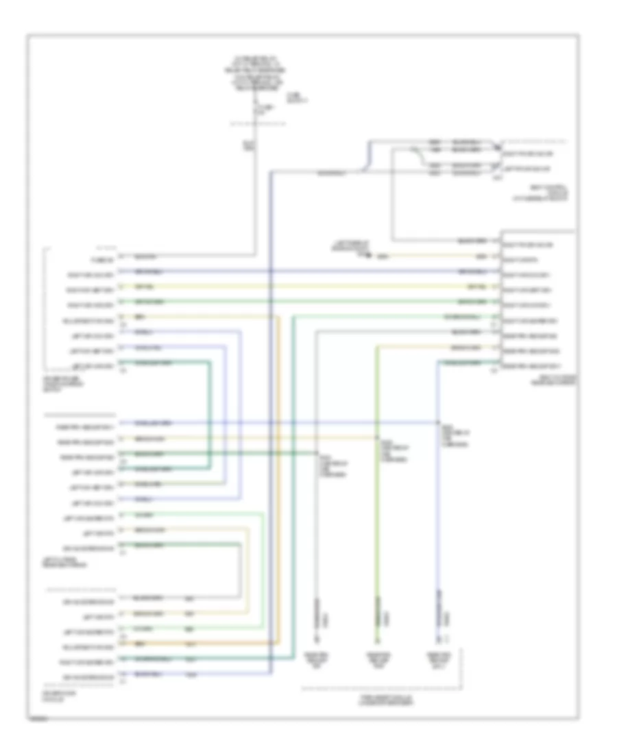 https://portal-diagnostov.com/license.html
Automotive Electricians Portal FZCO
Automotive Electricians Portal FZCO
https://portal-diagnostov.com/license.html
https://portal-diagnostov.com/license.html
Automotive Electricians Portal FZCO
Automotive Electricians Portal FZCOList of elements for Power Mirrors Wiring Diagram for Dodge Sprinter 2007 3500:
- (left rear of engine compt) g302
- (w/ relief relay) hot w/ terminal 15 relief relay energized
- (w/o relief relay) hot w/ terminal 15r relay energized
- Adjustment mir gnd
- Body control module (in fuse/relay block)
- Dir ind exterior mir
- Driver door module
- Driver power window/mirror switch
- Fuse 1 5a
- Fuse block 3
- Fused b+
- Left fr dir ind mir
- Left mir com drv
- Left mir heater rtn
- Left mir hor drv
- Left mir rtn
- Left mir vert drv
- Left outside rearview mirror
- Park assist module (under driver's seat)
- Rear prk ass dsp gnd
- Rear prk ass dsp sig
- Rear prk ass dsp sply
- Right fr dir ind mir
- Right mir com drv
- Right mir heater drv
- Right mir hor drv
- Right mir rtn
- Right mir vert drv
- Right outside rearview mirror
- S324 (center of cab overhead)
- S325 (center of cab overhead)
- S326 (center of cab overhead)
- U3622
- U3623
- U3624
POWER SEATS
Power Seats Wiring Diagram for Dodge Sprinter 2007 3500
 https://portal-diagnostov.com/license.html
Automotive Electricians Portal FZCO
Automotive Electricians Portal FZCO
https://portal-diagnostov.com/license.html
https://portal-diagnostov.com/license.html
Automotive Electricians Portal FZCO
Automotive Electricians Portal FZCOList of elements for Power Seats Wiring Diagram for Dodge Sprinter 2007 3500:
- Driver cushion pad heater
- Driver seat back heater
- Driver seat junction block
- Fuse 14 30a
- Fuse 4 5a
- Fuse block 2 (top of fuse/ relay box)
- Fuse/relay block (behind left kick panel)
- Fused b(+)
- G200 (right rear of engine compt)
- G305 (lower left side of vehicle)
- Ground
- Hot at all times
- Left htd seat
- Passenger cushion pad heater
- Passenger seat back heater
- Passenger seat junction block
- Red
- Right htd seat
- S221
- Sear driver
- Switch bank module
- U758
POWER TOP/SUNROOF
Power Top/Sunroof Wiring Diagram for Dodge Sprinter 2007 3500
 https://portal-diagnostov.com/license.html
Automotive Electricians Portal FZCO
Automotive Electricians Portal FZCO
https://portal-diagnostov.com/license.html
https://portal-diagnostov.com/license.html
Automotive Electricians Portal FZCO
Automotive Electricians Portal FZCOList of elements for Power Top/Sunroof Wiring Diagram for Dodge Sprinter 2007 3500:
- (left front headliner) g300
- (or 689)
- (or 690)
- Direction
- Direction sig
- Fuse 25a
- Fuse block 5
- Fused b(+)
- Gnd
- Hot at all times
- Motor ctrl
- Motor gnd
- Position
- Position sig
- Roof control module (in roof console)
- Sensor gnd
- Sunroof motor (at sunroof)
POWER WINDOWS
Power Windows Wiring Diagram for Dodge Sprinter 2007 3500
 https://portal-diagnostov.com/license.html
Automotive Electricians Portal FZCO
Automotive Electricians Portal FZCO
https://portal-diagnostov.com/license.html
https://portal-diagnostov.com/license.html
Automotive Electricians Portal FZCO
Automotive Electricians Portal FZCOList of elements for Power Windows Wiring Diagram for Dodge Sprinter 2007 3500:
- Body control module (in fuse/relay box)
- Bus (+)
- Bus (-)
- Child safety locks
- Computer data lines system
- Driver door module
- Driver panel lamps
- Driver power window/ mirror switch
- Driver pwr wind sw
- Driver wind (down)
- Driver wind (up)
- Driver wind sw mux
- Driver window motor (in driver's door)
- Fuse 1 5a
- Fuse 2 25a
- Fuse block 3
- Fuse/ relay block (behind left kick panel)
- Fused (b+)
- Fused b(+)
- G302 (left rear of engine compt)
- Gnd
- Hot at all times
- Ignition switch
- Left rear vent window motor (left rear of vehicle)
- Lh vent wind sw mux
- Lr vent wind dr (close)
- Lr vent wind dr (open)
- Master sw pass wind mux
- Master wind sw rtn
- Panel lamps driver
- Pass wind (down)
- Pass wind (up)
- Pass wind sw mux
- Pass wind sw rtn
- Passenger power window switch
- Passenger window motor (in passenger's door)
- Rh vent wind sw mux
- Right rear vent window motor (right rear of vehicle)
- Rr vent wind dr (close)
- Rr vent wind dr (open)
- S200 (instrument panel)
- S210
- Term 15
- U815
RADIO
Radio Wiring Diagram, Sound 20 for Dodge Sprinter 2007 3500
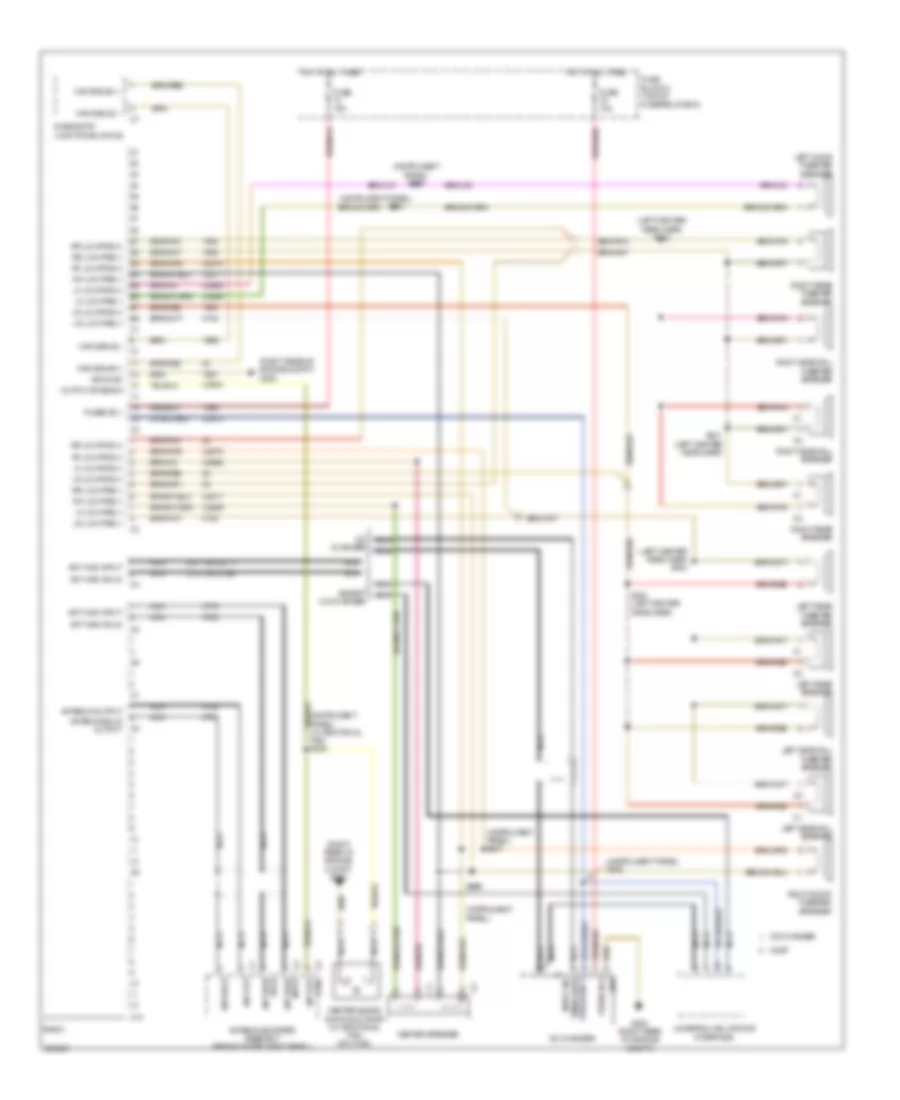 https://portal-diagnostov.com/license.html
Automotive Electricians Portal FZCO
Automotive Electricians Portal FZCO
https://portal-diagnostov.com/license.html
https://portal-diagnostov.com/license.html
Automotive Electricians Portal FZCO
Automotive Electricians Portal FZCOList of elements for Radio Wiring Diagram, Sound 20 for Dodge Sprinter 2007 3500:
- (instrument panel)
- (instrument panel) s205
- (instrument panel) s207
- (instrument panel) s209
- (left center headliner) s332
- (left center headliner) s333
- (or 2136)
- (or 2217)
- (right rear of engine compt) g200
- Ant high input
- Ant high shld
- Ant out
- Ant out ctrl
- Ant shld
- Antenna booster assembly (behind instrument panel)
- Antenna output
- Antenna shld output
- B1 rr low fre (+)
- B2 rr low fre (-)
- B3 rf low fre (+)
- B4 rf low fre (-)
- B5 lf low fre (+)
- B6 lf low fre (-)
- B7 lr low fre (+)
- B8 lr low fre (-)
- C10
- Can b bus(+)
- Can b bus(-)
- Cd changer
- Center blend door actuator (w/ additional fan) (on hvac)
- Center speaker
- Diagnostic junction block 25
- Except cd changer
- Fan) s208
- Fuse 10a
- Fuse 15a
- Fuse block 2 (top of fuse/relay box)
- Fused b(+)
- G200 (right rear of engine compt)
- Gnd
- Ground
- Hot at all times
- Left door tweeter speaker
- Left rear speaker
- Left rear tweeter speaker
- Left sidewall speaker
- Left sidewall tweeter speaker
- Lf low fre (+)
- Lf low fre (-)
- Lr low fre (+)
- Lr low fre (-)
- Most
- Nca
- Nca tenna high input-an-
- Output antenna
- Radio
- Rf low fre (+)
- Rf low fre (-)
- Right door tweeter speaker
- Right rear speaker
- Right rear tweeter speaker
- Right sidewall speaker
- Right sidewall tweeter speaker
- Rr low fre (+)
- Rr low fre (-)
- S204
- S206
- S331 (left center headliner)
- S334 (left center headliner)
- U2868
- U2869
- U2870
- U2871
- U2884
- U3510
- Universal cellphone interface
Radio Wiring Diagram, Sound 5 with Preinstallation for Dodge Sprinter 2007 3500
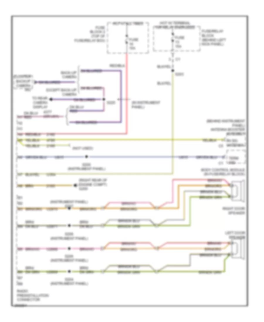 https://portal-diagnostov.com/license.html
Automotive Electricians Portal FZCO
Automotive Electricians Portal FZCO
https://portal-diagnostov.com/license.html
https://portal-diagnostov.com/license.html
Automotive Electricians Portal FZCO
Automotive Electricians Portal FZCOList of elements for Radio Wiring Diagram, Sound 5 with Preinstallation for Dodge Sprinter 2007 3500:
- (behind instrument panel) antenna booster assembly
- (in instrument panel)
- (instrument panel) s207
- (not used)
- (or u61)
- (right rear of engine compt) g200
- Body control module (in fuse/relay block)
- Camera sig
- Cluster
- Fuse 15a
- Fuse block 2 (top of fuse/relay box)
- Fuse/relay block (behind left kick panel)
- Hot at all times
- Hot w/ terminal 15r relay energized
- In sig antenna c5
- Left door speaker
- Radio preinstallation connector
- Right door speaker
- S200 (instrument panel)
- S203
- S204 (instrument panel)
- S205 (instrument panel)
- S206 (instrument panel)
- S225
- Term 58d
- To rear camera display
- U2868
- U2869
- U2870
- U2871
- U354
- U815
Radio Wiring Diagram, Sound 5 without PreInstallation for Dodge Sprinter 2007 3500
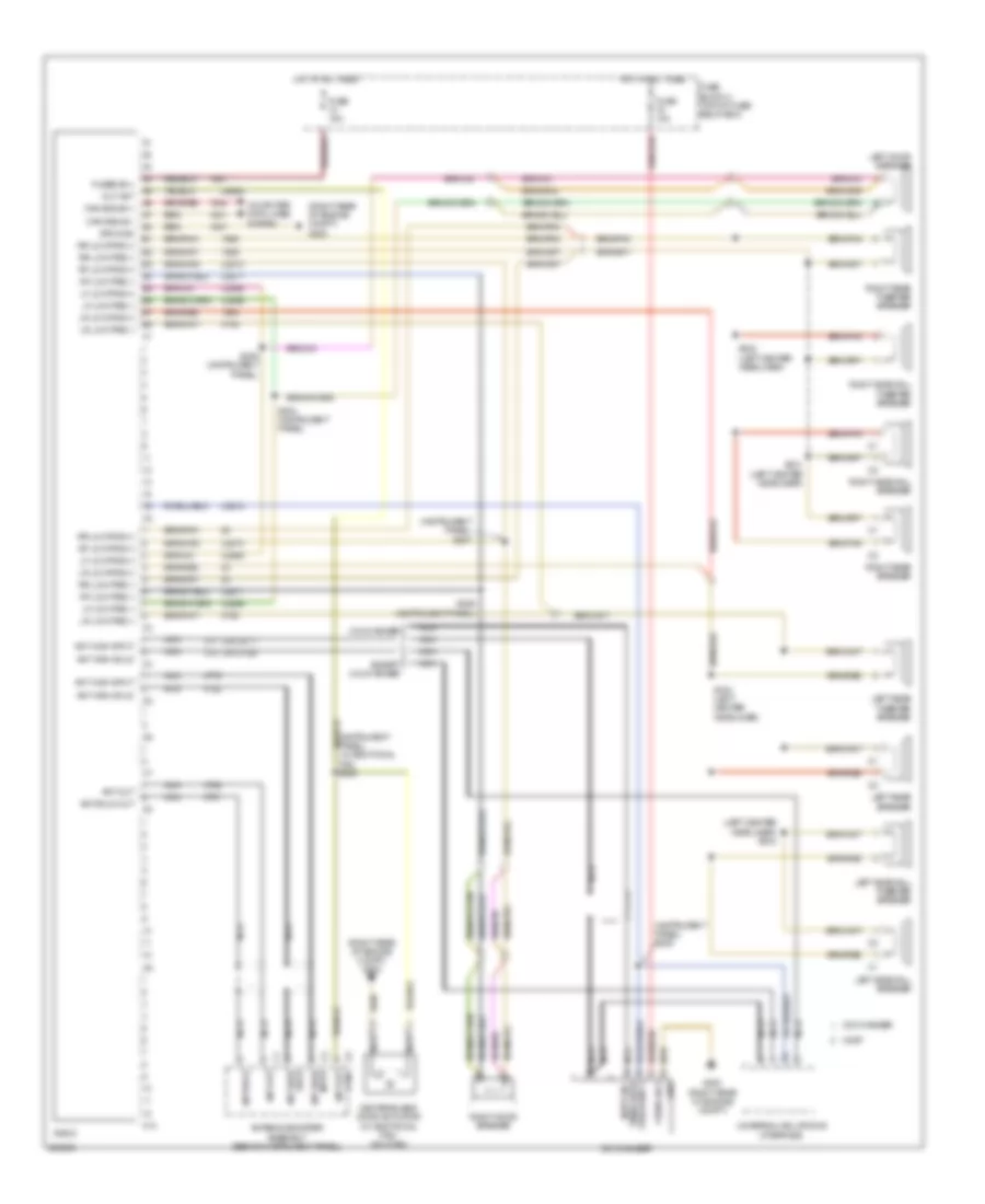 https://portal-diagnostov.com/license.html
Automotive Electricians Portal FZCO
Automotive Electricians Portal FZCO
https://portal-diagnostov.com/license.html
https://portal-diagnostov.com/license.html
Automotive Electricians Portal FZCO
Automotive Electricians Portal FZCOList of elements for Radio Wiring Diagram, Sound 5 without PreInstallation for Dodge Sprinter 2007 3500:
- (instrument panel) (w/ additional fan) s208
- (instrument panel) s207
- (instrument panel) s209
- (left center headliner) s333
- (or 2136)
- (or 2217)
- (right rear of engine compt) g200
- Ant high input
- Ant high shld
- Ant out
- Ant out ctrl
- Ant shld
- Ant shld out
- Antenna booster assembly (behind instrument panel)
- B1 rr low fre (+)
- B2 rr low fre (-)
- B3 rf low fre (+)
- B4 rf low fre (-)
- B5 lf low fre (+)
- B6 lf low fre (-)
- B7 lr low fre (+)
- B8 lr low fre (-)
- C10
- Can b bus(+)
- Can b bus(-)
- Cd changer
- Center blend door actuator (w/ additional fan) (on hvac)
- Computer data lines system
- Except cd changer
- Fuse 10a
- Fuse 15a
- Fuse block 2 (top of fuse/ relay box)
- Fused b(+)
- G200 (right rear of engine compt)
- Gnd
- Ground
- Hot at all times
- Left door speaker
- Left rear speaker
- Left rear tweeter speaker
- Left sidewall speaker
- Left sidewall tweeter speaker
- Lf low fre (+)
- Lf low fre (-)
- Lr low fre (+)
- Lr low fre (-)
- Most
- Nca
- Out ant
- Radio
- Rf low fre (+)
- Rf low fre (-)
- Right door speaker
- Right rear speaker
- Right rear tweeter speaker
- Right sidewall speaker
- Right sidewall tweeter speaker
- Rr low fre (+)
- Rr low fre (-)
- S204 (instrument panel)
- S205 (instrument panel)
- S206 (instrument panel)
- S331 (left center headliner)
- S332 (left center headliner)
- S334 (left center headliner)
- U2868
- U2869
- U2870
- U2871
- U2884
- U3510
- Universal cellphone interface
SHIFT INTERLOCK
Shift Interlock Wiring Diagram for Dodge Sprinter 2007 3500
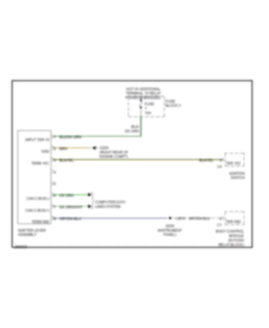 https://portal-diagnostov.com/license.html
Automotive Electricians Portal FZCO
Automotive Electricians Portal FZCO
https://portal-diagnostov.com/license.html
https://portal-diagnostov.com/license.html
Automotive Electricians Portal FZCO
Automotive Electricians Portal FZCOList of elements for Shift Interlock Wiring Diagram for Dodge Sprinter 2007 3500:
- Body control module (in fuse/ relay block)
- Can c bus(+)
- Can c bus(-)
- Computer data lines system
- Fuse 10a
- Fuse block 3
- G200 (right rear of engine compt)
- Gnd
- Hot w/ additional terminal 15 relay power energized
- Ignition switch
- Input ter 15
- S200 (instrument panel)
- Shifter lever assembly
- Ter 15c
- Ter 58d
- Term 15c
- Term 58d
- U815
Steering Column Wiring Diagram for Dodge Sprinter 2007 3500
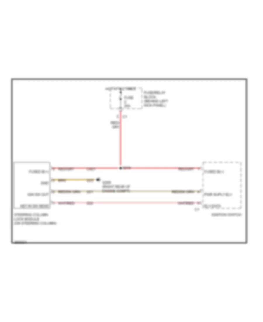 https://portal-diagnostov.com/license.html
Automotive Electricians Portal FZCO
Automotive Electricians Portal FZCO
https://portal-diagnostov.com/license.html
https://portal-diagnostov.com/license.html
Automotive Electricians Portal FZCO
Automotive Electricians Portal FZCOList of elements for Steering Column Wiring Diagram for Dodge Sprinter 2007 3500:
- Elv-data
- Fuse 25a
- Fuse/relay block (behind left kick panel)
- Fused b(+)
- G200 (right rear of engine compt)
- Gnd
- Hot at all times
- Ign sw out
- Ignition switch
- Key in sw sens
- Pwr suply elv
- S210
- Steering column lock module (on steering column)
- U421
STARTING/CHARGING
Charging Wiring Diagram for Dodge Sprinter 2007 3500
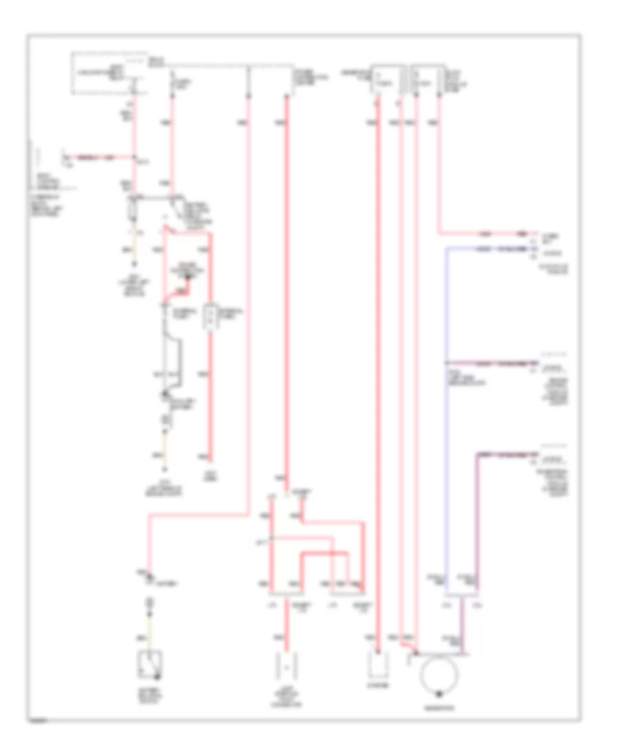 https://portal-diagnostov.com/license.html
Automotive Electricians Portal FZCO
Automotive Electricians Portal FZCO
https://portal-diagnostov.com/license.html
https://portal-diagnostov.com/license.html
Automotive Electricians Portal FZCO
Automotive Electricians Portal FZCOList of elements for Charging Wiring Diagram for Dodge Sprinter 2007 3500:
- (not used)
- 100a
- 3.0l
- 3.5l
- 300a
- Auxiliary battery
- Battery
- Battery isolation switch
- Battery isolator relay (in engine compt)
- Body control module
- Body manufacturer d+ relay
- Engine control module (in engine compt)
- Except lt3
- External fuse 1
- External fuse 2
- Fuse 4 150a
- Fuse/relay block (behind left kick panel)
- Fused b(+) c1
- G101 (left rear of engine compt)
- G301 (lower left side of vehicle)
- Generator
- Generator fuse
- Glow plug module
- Glow plug module fuse
- Jump starting point connector
- Lin bus
- Lt3
- Power distribution center
- Power distribution system
- Powertrain control module (in engine compt)
- Red
- Relay block
- S100 (left side engine compt)
- S117
- S313
- Starter
- U2032
- U261
Starting Wiring Diagram for Dodge Sprinter 2007 3500
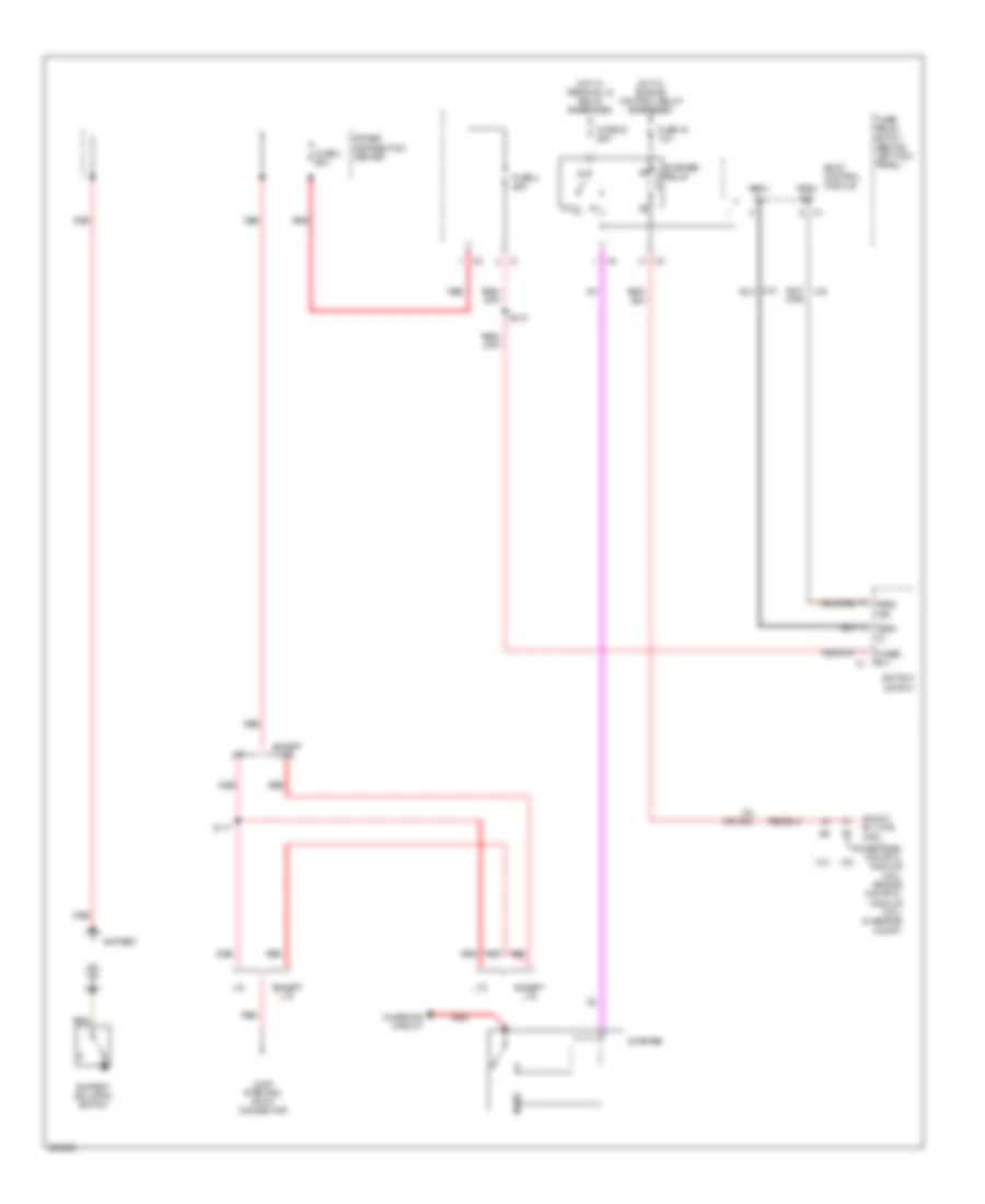 https://portal-diagnostov.com/license.html
Automotive Electricians Portal FZCO
Automotive Electricians Portal FZCO
https://portal-diagnostov.com/license.html
https://portal-diagnostov.com/license.html
Automotive Electricians Portal FZCO
Automotive Electricians Portal FZCOList of elements for Starting Wiring Diagram for Dodge Sprinter 2007 3500:
- (or 293)
- 3.0l
- 3.5l
- 87a
- Battery
- Battery isolation switch
- Body control module
- Charging circuit
- Eng st rly mtr ctrl
- Except lt3
- Fuse 16 10a
- Fuse 2 25a
- Fuse 23 25a
- Fuse 3 80a
- Fuse/ relay block (behind left kick panel)
- Fused b(+)
- Hot w/ engine control relay energized
- Hot w/ terminal 15 relay energized
- Ignition switch
- Jump starting point connector
- Lt3
- Power distribution center
- Powertrain control module (3.5l) engine control module (3.0l) (in engine compt)
- Red
- S117
- S210
- Starter
- Starter relay
- Term
- Term 15r
SUPPLEMENTAL RESTRAINTS
Supplemental Restraints Wiring Diagram (1 of 2) for Dodge Sprinter 2007 3500
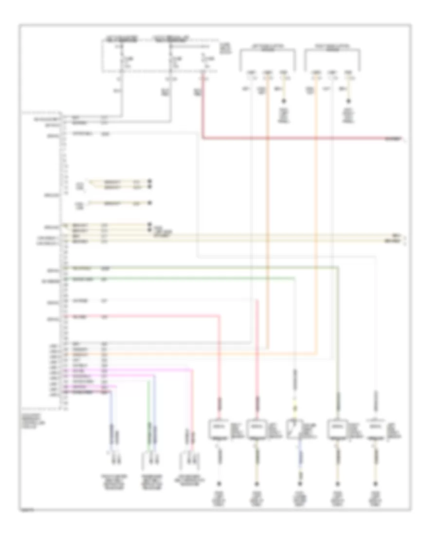 https://portal-diagnostov.com/license.html
Automotive Electricians Portal FZCO
Automotive Electricians Portal FZCO
https://portal-diagnostov.com/license.html
https://portal-diagnostov.com/license.html
Automotive Electricians Portal FZCO
Automotive Electricians Portal FZCOList of elements for Supplemental Restraints Wiring Diagram (1 of 2) for Dodge Sprinter 2007 3500:
- Can b bus (+)
- Can b bus (-)
- Driver seat belt retractor tensioner
- Driver seat belt switch
- Front center seat belt retractor tensioner
- Fuse 10a
- Fuse 5a
- Fuse/ relay block
- G301 (under driver seat)
- G302 (left kick panel)
- G306 (left side of dash)
- G307 (right kick panel)
- Gnd
- Ground
- High line
- Hot w/ run/start relay energized
- Hot w/ terminal 15r relay energized
- Ign run
- Ign run/start
- Left side curtain air bag
- Left side impact sensor
- Line 1
- Line 2
- Low line
- Occupant restraint controller module
- Passenger seat belt retractor tensioner
- Right side curtain air bag
- Right side impact sensor
- Signal
- Sw sense
Supplemental Restraints Wiring Diagram (2 of 2) for Dodge Sprinter 2007 3500
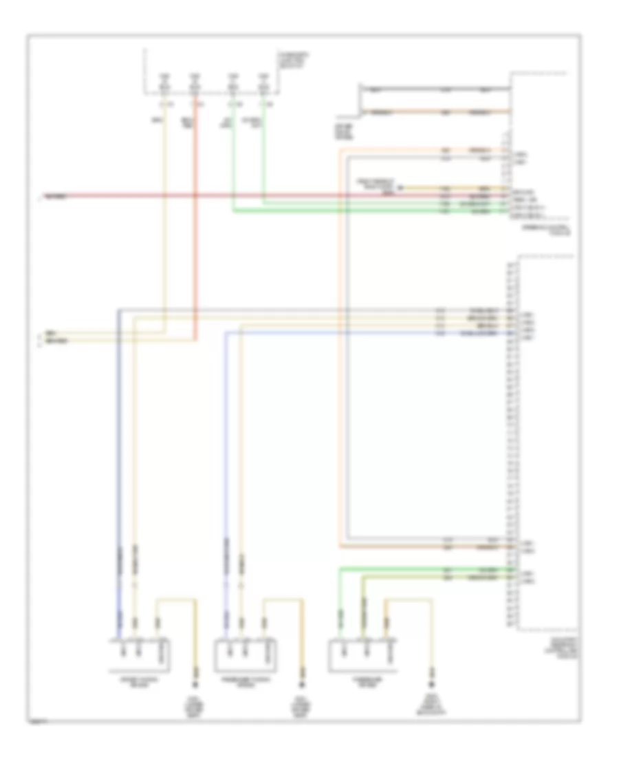 https://portal-diagnostov.com/license.html
Automotive Electricians Portal FZCO
Automotive Electricians Portal FZCO
https://portal-diagnostov.com/license.html
https://portal-diagnostov.com/license.html
Automotive Electricians Portal FZCO
Automotive Electricians Portal FZCOList of elements for Supplemental Restraints Wiring Diagram (2 of 2) for Dodge Sprinter 2007 3500:
- (right rear of eng compt) g200
- Can b bus (+)
- Can b bus (-)
- Can c bus (+)
- Can c bus (-)
- Diagnostic junction block 27
- Driver squib air bag
- Driver thorax air bag
- G200 (right rear of eng compt)
- G301 (under driver seat)
- Ground
- Line 1
- Line 2
- Occupant restraint controller module
- Passenger air bag
- Passenger thorax air bag
- Steering control module
- Term. 15r
TRANSMISSION
Transmission Wiring Diagram for Dodge Sprinter 2007 3500
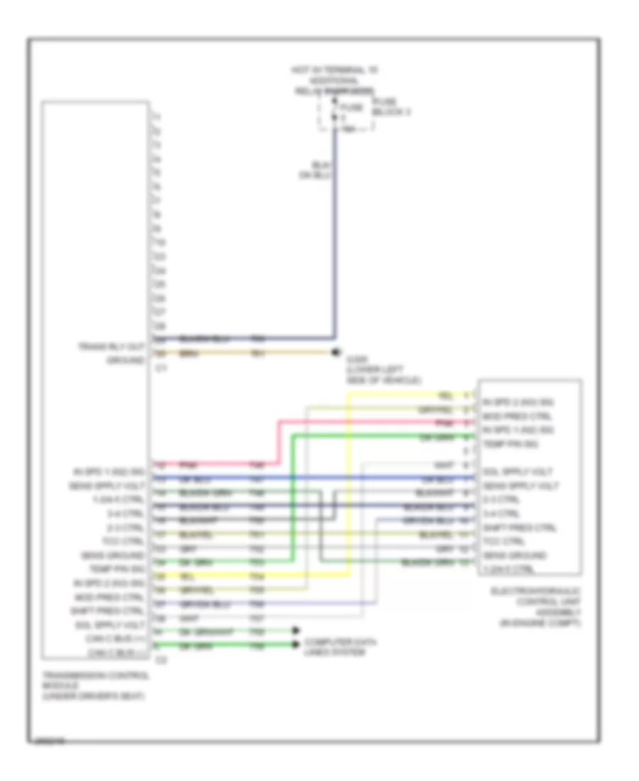 https://portal-diagnostov.com/license.html
Automotive Electricians Portal FZCO
Automotive Electricians Portal FZCO
https://portal-diagnostov.com/license.html
https://portal-diagnostov.com/license.html
Automotive Electricians Portal FZCO
Automotive Electricians Portal FZCOList of elements for Transmission Wiring Diagram for Dodge Sprinter 2007 3500:
- 1-2/4-5 ctrl
- 2-3 ctrl
- 3-4 ctrl
- Can c bus (+)
- Can c bus (-)
- Computer data lines system
- Electrohydraulic control unit assembly (in engine compt)
- Fuse 10a
- Fuse block 3
- G305 (lower left side of vehicle)
- Ground
- Hot w/ terminal 15 additional relay energized
- In spd 1 (n2) sig
- In spd 2 (n3) sig
- Mod pres ctrl
- Pnk
- Sens ground
- Shift pres ctrl
- Tcc ctrl
- Temp p/n sig
- Trans rly out
- Transmission control module (under driver's seat)
WARNING SYSTEMS
Brake Wear Sensor Wiring Diagram for Dodge Sprinter 2007 3500
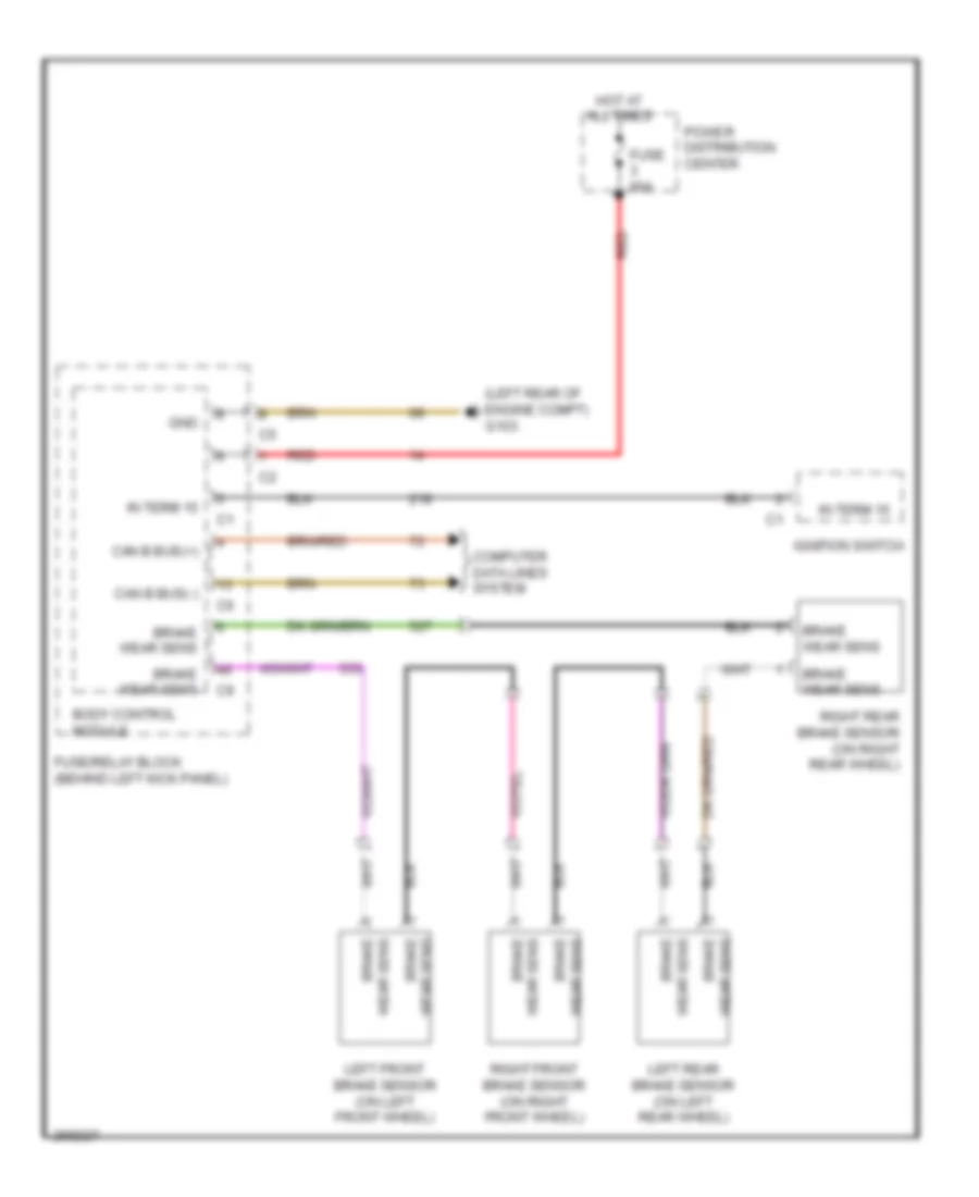 https://portal-diagnostov.com/license.html
Automotive Electricians Portal FZCO
Automotive Electricians Portal FZCO
https://portal-diagnostov.com/license.html
https://portal-diagnostov.com/license.html
Automotive Electricians Portal FZCO
Automotive Electricians Portal FZCOList of elements for Brake Wear Sensor Wiring Diagram for Dodge Sprinter 2007 3500:
- (left rear of engine compt) g103
- Body control module
- Brake
- Brake wear sens
- Can b bus(+)
- Can b bus(-)
- Computer data lines system
- Fuse 80a
- Fuse/relay block (behind left kick panel)
- Gnd
- Hot at all times
- Ignition switch
- In term 15
- Left front brake sensor (on left front wheel)
- Left rear brake sensor (on left rear wheel)
- Power distribution center
- Red
- Right front brake sensor (on right front wheel)
- Right rear brake sensor (on right rear wheel)
- Wear sens
Tire Pressure Monitoring Wiring Diagram for Dodge Sprinter 2007 3500
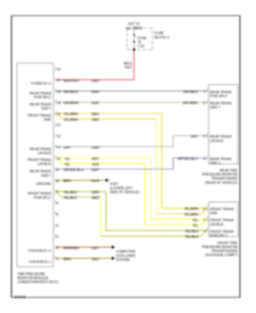 https://portal-diagnostov.com/license.html
Automotive Electricians Portal FZCO
Automotive Electricians Portal FZCO
https://portal-diagnostov.com/license.html
https://portal-diagnostov.com/license.html
Automotive Electricians Portal FZCO
Automotive Electricians Portal FZCOList of elements for Tire Pressure Monitoring Wiring Diagram for Dodge Sprinter 2007 3500:
- Can b bus (+)
- Can b bus (-)
- Computer data lines system
- Front tire pressure monitor transponder (in engine compt)
- Front trans gnd
- Front trans lin bus
- Front trans pwr sply
- Fuse 7.5a
- Fuse block 4
- Fused b (+)
- G301 (lower left side of vehicle)
- Ground
- Hot at all times
- Rear tire pressure monitor transponder (rear of vehicle)
- Rear trans gnd 1
- Rear trans lin bus
- Rear trans pwr sply
- Tire pressure monitor module (under driver's seat)
WIPER/WASHER
Front Wiper/Washer Wiring Diagram for Dodge Sprinter 2007 3500
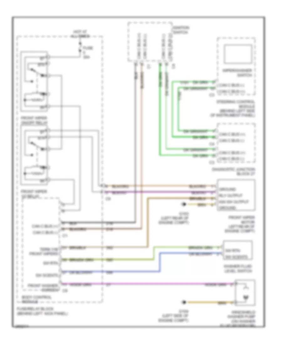 https://portal-diagnostov.com/license.html
Automotive Electricians Portal FZCO
Automotive Electricians Portal FZCO
https://portal-diagnostov.com/license.html
https://portal-diagnostov.com/license.html
Automotive Electricians Portal FZCO
Automotive Electricians Portal FZCOList of elements for Front Wiper/Washer Wiring Diagram for Dodge Sprinter 2007 3500:
- 87a
- Body control module
- Can c bus (+)
- Can c bus (-)
- Diagnostic junction block 27
- Front washer screen c9
- Front wiper 1/2 relay
- Front wiper motor left rear of engine compt)
- Front wiper on/off relay
- Fuse 30a
- Fuse/relay block (behind left kick panel)
- G103 (left rear of engine compt)
- G104 (left side of engine compt)
- Ground
- Hot at all times
- Ign sw output
- Ignition switch
- Rly output
- Steering control module (behind left side of instrument panel)
- Sw rtn
- Sw scents
- Term 31b front wipers
- Washer fluid level switch
- Windshield washer pump (on washer fluid reservoir)
- Wiper/washer switch
Headlamp Washer Wiring Diagram for Dodge Sprinter 2007 3500
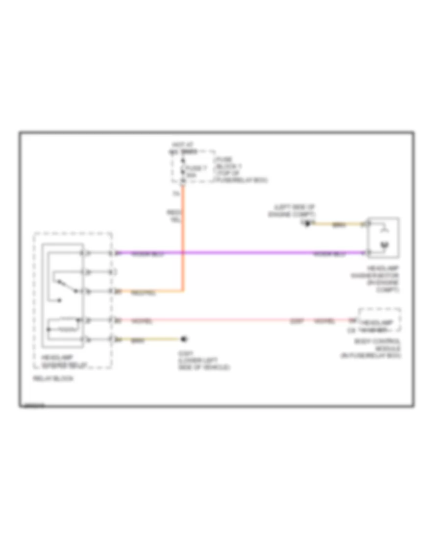 https://portal-diagnostov.com/license.html
Automotive Electricians Portal FZCO
Automotive Electricians Portal FZCO
https://portal-diagnostov.com/license.html
https://portal-diagnostov.com/license.html
Automotive Electricians Portal FZCO
Automotive Electricians Portal FZCOList of elements for Headlamp Washer Wiring Diagram for Dodge Sprinter 2007 3500:
- (left side of engine compt) g104
- Body control module (in fuse/relay box)
- Fuse 7 30a
- Fuse block 1 (top of fuse/relay box)
- G301 (lower left side of vehicle)
- Headlamp washer c9
- Headlamp washer motor (in engine compt)
- Headlamp washer relay
- Hot at all times
- Relay block
Rear Wiper/Washer Wiring Diagram for Dodge Sprinter 2007 3500
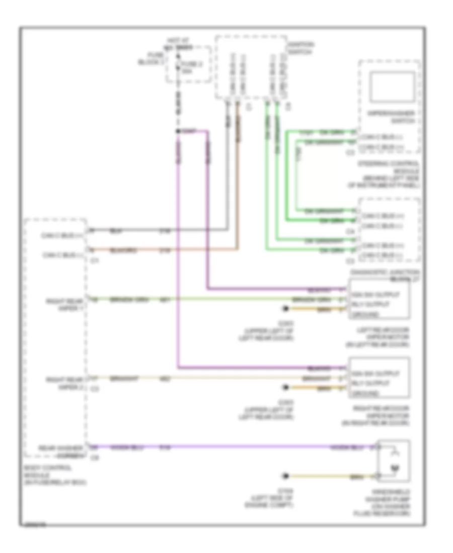 https://portal-diagnostov.com/license.html
Automotive Electricians Portal FZCO
Automotive Electricians Portal FZCO
https://portal-diagnostov.com/license.html
https://portal-diagnostov.com/license.html
Automotive Electricians Portal FZCO
Automotive Electricians Portal FZCOList of elements for Rear Wiper/Washer Wiring Diagram for Dodge Sprinter 2007 3500:
- Body control module (in fuse/relay box)
- Can c bus (+)
- Can c bus (-)
- Diagnostic junction block 27
- Fuse 2 30a
- Fuse block 3
- G104 (left side of engine compt)
- G303 (upper left of left rear door)
- Ground
- Hot at all times
- Ign sw output
- Ignition switch
- Left rear door wiper motor (in left rear door)
- Rear washer screen c9
- Right rear door wiper motor (in right rear door)
- Right rear wiper 1
- Right rear wiper 2 c3
- Rly output
- S347
- Steering control module (behind left side of instrument panel)
- Windshield washer pump (on washer fluid reservoir)
- Wiper/washer switch

 Čeština
 Dansk
Dansk Deutsch
 Ελληνικά
 English
 English
 Español
 Suomi
Suomi Français
 Français
 עברית
עברית Hrvatski
 Magyar
 Italiano
 한국어
한국어 Nederlands
 Polski
 Português
 Português
 Română
 Русский
 Slovenčina
 Slovenščina
 Svenska
 Türkçe
 中文 (中国)
