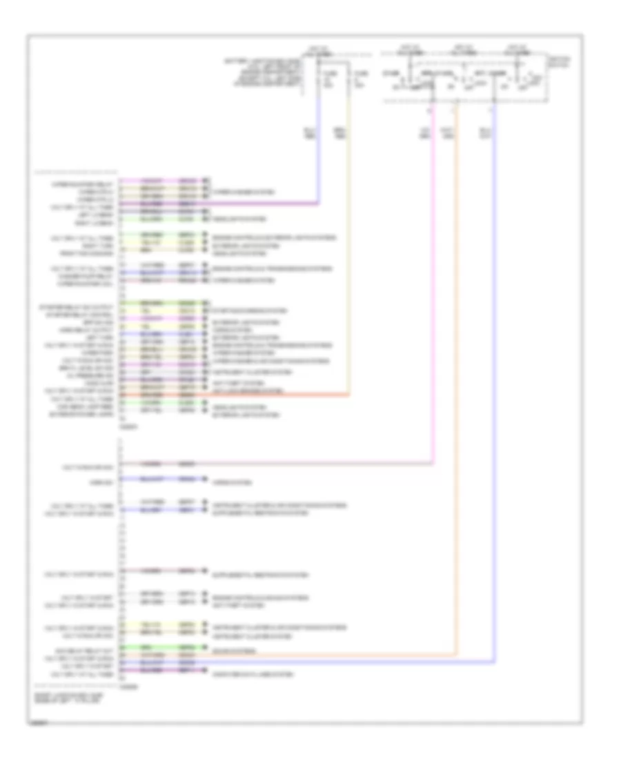
AIR CONDITIONING
Automatic A/C Wiring Diagram (1 of 3) for Ford Fusion S 2007
 https://portal-diagnostov.com/license.html
Automotive Electricians Portal FZCO
Automotive Electricians Portal FZCO
https://portal-diagnostov.com/license.html
https://portal-diagnostov.com/license.html
Automotive Electricians Portal FZCO
Automotive Electricians Portal FZCO
List of elements for Automatic A/C Wiring Diagram (1 of 3) for Ford Fusion S 2007:
- (in main harn, near breakout to c251) s228
- (in steering wheel jumper harness, near breakout to c2999) s201
- Actuators return
- Air bag sliding contact (behind steering wheel assembly)
- Ambient air temperature sensor (3.0l: behind front grille) (2.3l: right side of radiator support)
- Ambient temp sensor
- Battery
- Battery junction box (bjb) (2.3l: left side of engine compt) (3.0l: left front of engine compt)
- Blend fbk
- Blend input
- Blower motor (right side of dash)
- Blower motor relay
- C218a
- C218b
- C228a
- C228b
- Cbp20
- Ch122
- Ch123
- Ch207
- Ch208
- Ch228
- Ch229
- Ch233
- Ch234
- Chs04
- Chs09
- Chs13
- Chs14
- Chs29
- Chs30
- Cmd
- Computer data lines system
- Def request
- Defogger system
- Dr hs request
- Dr hshi
- Dr hslo
- Dr sunload sens
- Electronic automatic temperature control (eatc) module (center of dash)
- Fan+
- Fan-
- Front blower motor speed controller (right side of dash)
- Fuse 40a
- G201 (center of dash)
- G202 (left side of dash)
- Gd116
- Gnd
- Headlights system
- Hot at all times
- Ign feed
- In car temp
- In-vehicle temperature sensor (left side of dash)
- Left steering wheel switch
- Lh111
- Mode actuator fbk
- Mode input
- Motor+
- Motor-
- Ms can +
- Ms can -
- Pass hshi
- Pass request
- Pss hslo
- Recirc ccw
- Recirc cw
- Redundant cc return
- Redundant cc signal
- Rh104
- Rh106
- Rh111
- Run/start
- Sbp07
- Seats system
- Sensor ret 4
- Sunload sensor (right side of dash)
- Vdb06
- Vdb07
- Vh101
- Vh407
- Vh414
- Vh416
- Vh436
- Vh439
- Vh444
- Vpwr
- Vref actuators
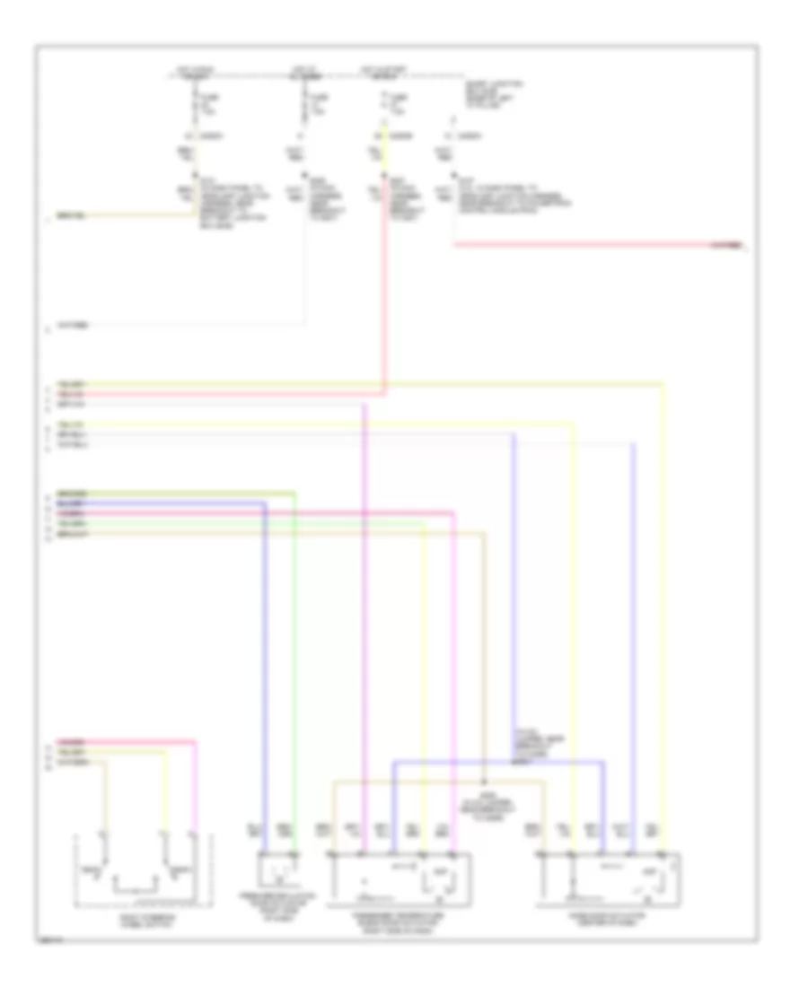
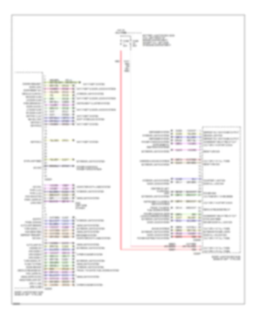
Automatic A/C Wiring Diagram (2 of 3) for Ford Fusion S 2007
 https://portal-diagnostov.com/license.html
Automotive Electricians Portal FZCO
Automotive Electricians Portal FZCO
https://portal-diagnostov.com/license.html
https://portal-diagnostov.com/license.html
Automotive Electricians Portal FZCO
Automotive Electricians Portal FZCOList of elements for Automatic A/C Wiring Diagram (2 of 3) for Ford Fusion S 2007:
- (in a/c jumper, near breakout to c2295) s204
- Amp
- C2280a
- C2280b
- Fresh/recirculation door actuator (right side of dash)
- Fuse 7.5a
- Harness, near breakout to c251)
- Harness, near breakout to g201)
- Headlamp junction harness, near breakout to battery junction box (bjb))
- Headlamp junction harness, near breakout to powertrain control module (pcm))
- Hot at all times
- Hot in run or acc
- Hot in start or run
- Mode door actuator (center of dash)
- Passenger temperature blend door actuator (right side of dash)
- Right steering wheel switch
- S206 (in a/c jumper, near breakout to c2295)
- Smart junction box (sjb) (base of left "a" pillar)
- Temp+
- Temp-
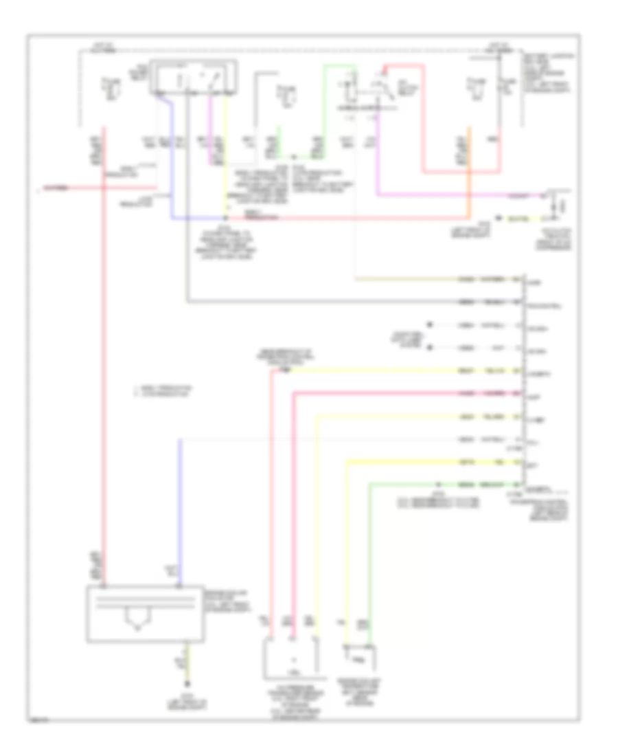
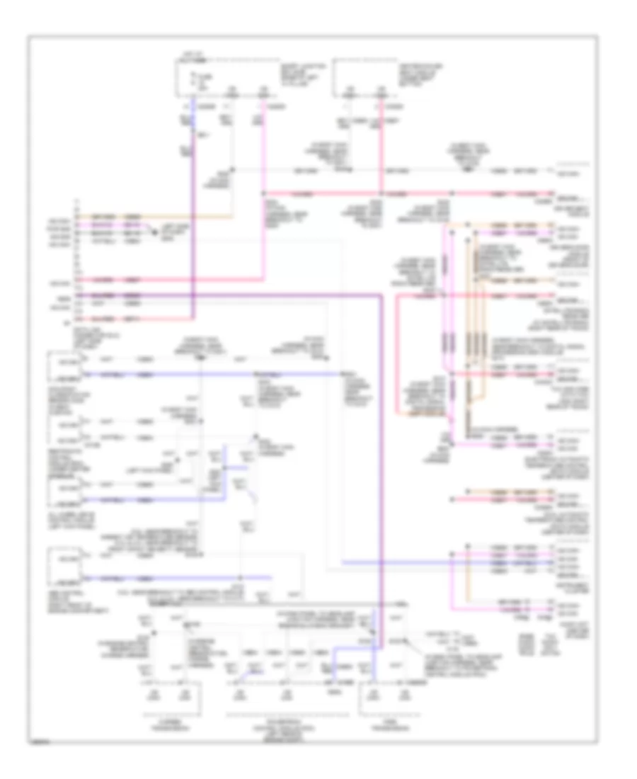
Automatic A/C Wiring Diagram (3 of 3) for Ford Fusion S 2007
 https://portal-diagnostov.com/license.html
Automotive Electricians Portal FZCO
Automotive Electricians Portal FZCO
https://portal-diagnostov.com/license.html
https://portal-diagnostov.com/license.html
Automotive Electricians Portal FZCO
Automotive Electricians Portal FZCOList of elements for Automatic A/C Wiring Diagram (3 of 3) for Ford Fusion S 2007:
- (3.0l: center rear of engine compt)
- (in dash panel to headlamp junction harness, near breakout to battery junction box (bjb))
- (near breakout of powertrain control module (pcm)) s124
- A/c clutch field coil (front of a/c compressor)
- A/c clutch relay
- A/c pressure transducer sensor (2.3l: right front of engine)
- Accr
- Acpt
- Battery junction box (bjb) (2.3l: left side of engine compt) (3.0l: left front of engine compt)
- C-sigrtn
- C-vref
- C175b
- C175e
- Ce302
- Ch302
- Computer data lines system
- E-sigrtn
- Early production
- Early production late production
- Ect
- Engine coolant temperature (ect) sensor (rear of engine)
- Engine cooling fan motor (3.0l: left front of engine compt)
- Fc-v
- Fuse 10a
- Fuse 15a
- Fuse 40a
- Fuse 60a
- G103 (left front of engine compt)
- Headlamp junction harness, near breakout to battery junction box (bjb))
- Hot at all times
- Hs can+
- Hs can-
- Late production
- Le424
- Pcm control
- Pcm power relay
- Powertrain control module (pcm) (left rear of engine compt)
- Re405
- Re407
- Red
- S102 (2.3l: near breakout to c175e) (3.0l: near breakout to c1450)
- S129 s142 (late production) (early production) (in dash panel to (2.3l: near breakout to battery junction box (bjb))
- S143
- Vdb04
- Vdb05
- Ve716
- Vec03
- Vh433
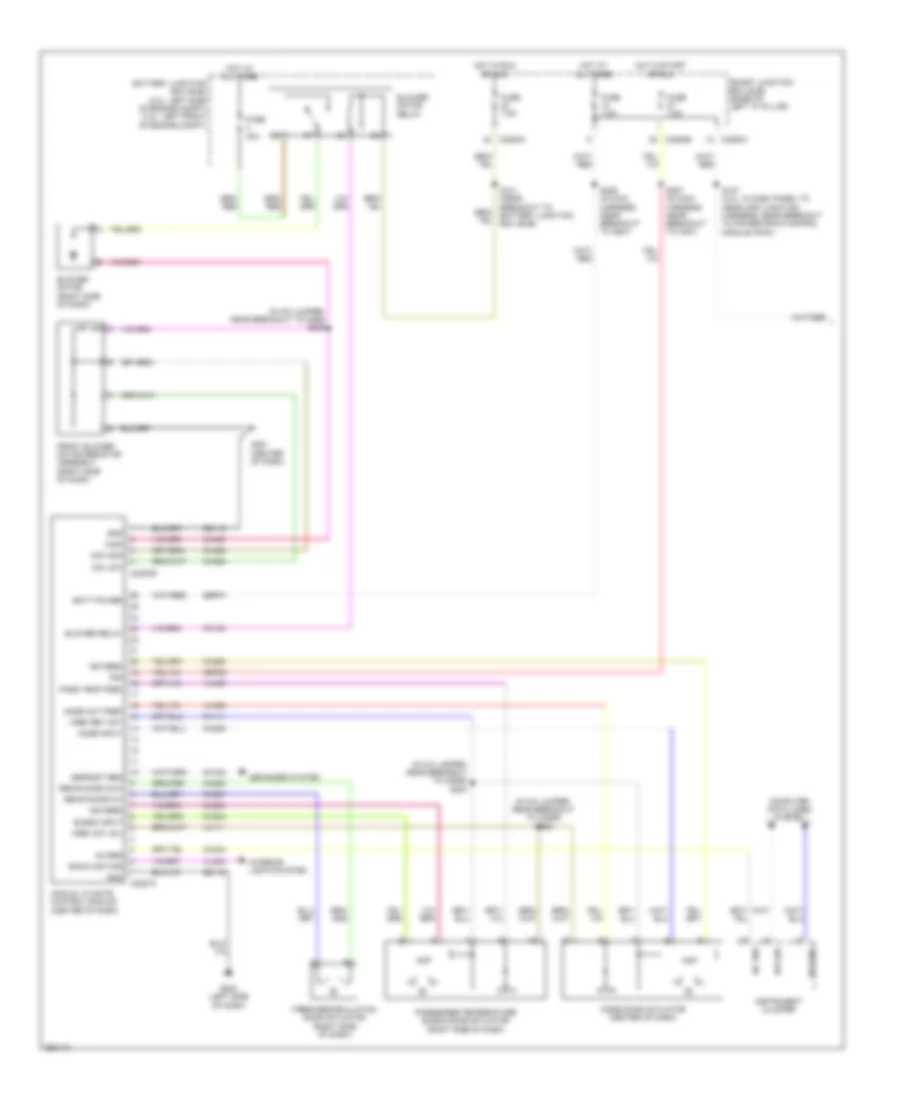
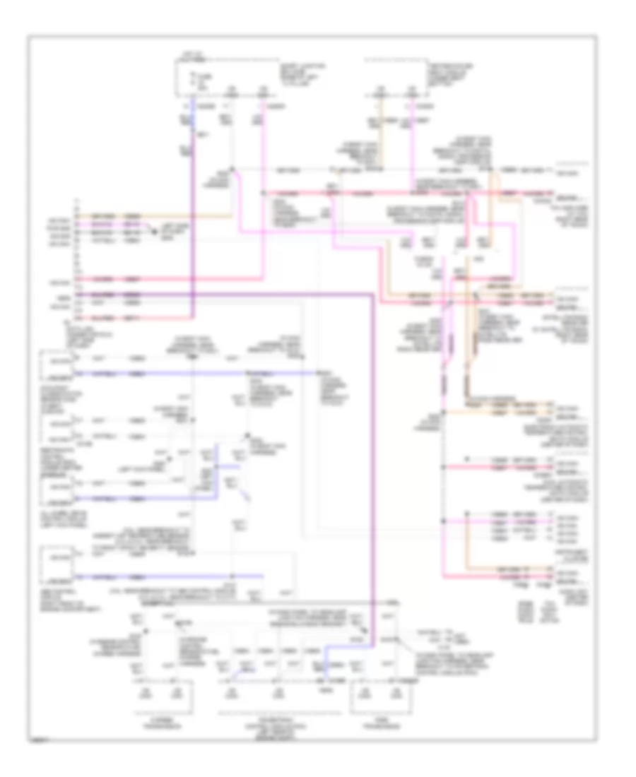
Manual A/C Wiring Diagram (1 of 2) for Ford Fusion S 2007
 https://portal-diagnostov.com/license.html
Automotive Electricians Portal FZCO
Automotive Electricians Portal FZCO
https://portal-diagnostov.com/license.html
https://portal-diagnostov.com/license.html
Automotive Electricians Portal FZCO
Automotive Electricians Portal FZCOList of elements for Manual A/C Wiring Diagram (1 of 2) for Ford Fusion S 2007:
- (center of dash)
- (in a/c jumper, near breakout to c2295) s204
- (in a/c jumper, near breakout to c2295) s206
- (in a/c jumper, near breakout to c298) s205
- A/c req
- Ac req
- Amp
- Backlighting
- Batt power
- Battery junction box (bjb) (2.3l: left side of engine compt) (3.0l: left front of engine compt)
- Blend input
- Blower motor (right side of dash)
- Blower motor relay
- Blower relay
- C2280a
- C2280b
- C2357a
- C2357b
- Cbp20
- Ch122
- Ch123
- Ch207
- Ch208
- Ch228
- Ch229
- Ch233
- Ch234
- Ch428
- Ch429
- Ch430
- Ch434
- Computer data lines system
- Defogger system
- Defrost req
- Fresh/recirculation door actuator (right side of dash)
- Front blower motor resistor assembly (right side of dash)
- Fuse 40a
- Fuse 7.5a
- G201
- G202 (left side of dash)
- Gd115
- Gd116
- Gnd
- High
- Hot at all times
- Hot in run or acc
- Hot in start or run
- Hs can+
- Hs can-
- Ign feed
- Instrument cluster
- Interior lights system
- Lh111
- Manual climate control module (center of dash)
- Mid high
- Mid low
- Mode act fdbk
- Mode door actuator (center of dash)
- Mode input
- Pass temp fdbk
- Passenger temperature blend door actuator (right side of dash)
- R/s
- Recir door ccw
- Recir door cw
- Rh111
- S127 (3.0l: in dash panel to headlamp junction harness, near breakout to powertrain control module (pcm))
- S131 (near breakout to battery junction box (bjb))
- S227 (in main harness, near breakout to c251)
- S229 (in main harness, near breakout to g201)
- Sbp07
- Smart junction box (sjb) (base of left "a" pillar)
- Vh436
- Vh439
- Vln04
- Vref act (5v)
- Vref ret act
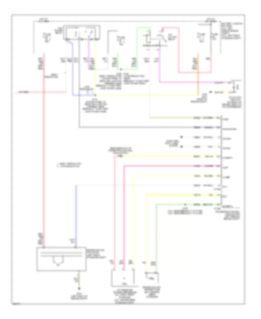
Manual A/C Wiring Diagram (2 of 2) for Ford Fusion S 2007
 https://portal-diagnostov.com/license.html
Automotive Electricians Portal FZCO
Automotive Electricians Portal FZCO
https://portal-diagnostov.com/license.html
https://portal-diagnostov.com/license.html
Automotive Electricians Portal FZCO
Automotive Electricians Portal FZCOList of elements for Manual A/C Wiring Diagram (2 of 2) for Ford Fusion S 2007:
- (3.0l: center rear of engine compt)
- (early production)
- (in dash panel to headlamp junction harness, near breakout to battery junction box (bjb))
- (near breakout of powertrain control module (pcm)) s124
- A/c clutch field coil (on front of engine, front of a/c compressor)
- A/c clutch relay
- A/c pressure transducer sensor (2.3l: right front of engine)
- Accr
- Acpt
- Battery junction box (bjb) (2.3l: left side of engine compt) (3.0l: left front of engine compt)
- Breakout to battery junction box (bjb))
- C-sigrtn
- C-vref
- C175b
- C175e
- Ce302
- Ch302
- Computer data lines system
- E-sigrtn
- Early production
- Early production late production
- Ect
- Engine coolant temperature (ect) sensor (rear of engine)
- Engine cooling fan motor (left front of engine compt)
- Fc-v
- Fuse 10a
- Fuse 15a
- Fuse 40a
- Fuse 60a
- G103 (left front of engine compt)
- Hot at all times
- Hs can+
- Hs can-
- Late production
- Le424
- Pcm control
- Pcm power relay
- Powertrain control module (pcm) (left rear of engine compt)
- Re405
- Re407
- Red
- S102 (2.3l: near breakout to c175e) (3.0l: near breakout to c1450)
- S129 s142 (late production) (near (in dash panel to headlamp junction harness, near breakout to battery junction box (bjb))
- S143
- Vdb04
- Vdb05
- Ve716
- Vec03
- Vh433
ANTI-LOCK BRAKES
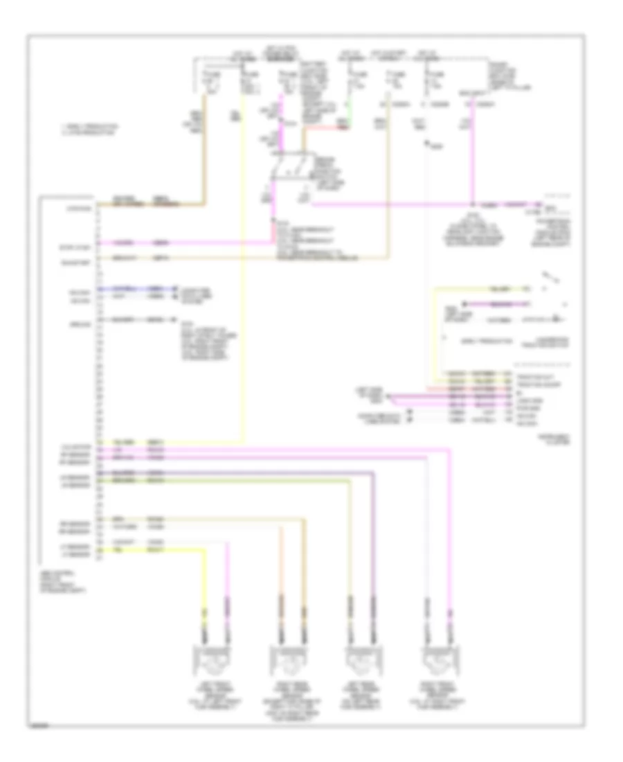
Anti-lock Brakes Wiring Diagram for Ford Fusion S 2007
 https://portal-diagnostov.com/license.html
Automotive Electricians Portal FZCO
Automotive Electricians Portal FZCO
https://portal-diagnostov.com/license.html
https://portal-diagnostov.com/license.html
Automotive Electricians Portal FZCO
Automotive Electricians Portal FZCOList of elements for Anti-lock Brakes Wiring Diagram for Ford Fusion S 2007:
- (left side of dash) g202
- Abs control module (right front of engine compt)
- Battery junction box (bjb) (3.0l: left front of engine compt) (except 3.0l: left side of engine compt)
- Boo
- Boo input
- Brake pedal position switch (left side of dash)
- C175b
- C2280a
- C2280b
- Cbp19
- Cca10
- Cca15
- Ccb08
- Ces09
- Computer data lines system
- Early production
- Early production late production
- Fuse 10a
- Fuse 15a
- Fuse 20a 30a
- Fuse 40a
- Fuse 7.5a
- G104 (2.3l: in front of right strut tower) (3.0l: right front of engine compt) (3.5l: right side of engine compt)
- G202 (left side of dash)
- Gd116
- Gd123
- Ground
- Hazard/pad traction switch
- Hot at all times
- Hot in start or run
- Hot w/ pcm power relay energized
- Hs can+
- Hs can-
- Instrument cluster
- Left front wheel speed sensor (3.5l: at left front hub assembly)
- Left rear wheel speed sensor (on left rear hub assembly)
- Lf sensor+
- Lf sensor-
- Logic gnd
- Lr sensor+
- Lr sensor-
- Mtr pwr
- Nca
- Powertrain control module (pcm) (left rear of engine compt)
- Pwr gnd
- Rca17
- Rca18
- Rca19
- Rca20
- Rf sensor+
- Rf sensor-
- Right front wheel speed sensor (3.5l: at right front hub assembly)
- Right rear wheel speed sensor (except mkz: base of right "c" pillar) (mkz: on right rear hub assembly)
- Rr sensor+
- Rr sensor-
- Run/start
- S120 (2.3l, 3.0l: in dash panel to headlamp junction harness, near engine bulkhead grommet)
- S133 (2.3l: near breakout to c1443) (3.0l: near breakout to g103) (3.5l: near breakout to powertrain control module)
- S144
- S229
- Sbb10
- Sbb36 (or sbb08)
- Sbp07
- Smart junction box (sjb) (base of left "a" pillar)
- Stop lp sw
- Traction on/off
- Traction out
- Valve pwr
- Vca03
- Vca04
- Vca05
- Vca06
- Vdb04
- Vdb05
ANTI-THEFT
Forced Entry Wiring Diagram, with Memory (1 of 2) for Ford Fusion S 2007
 https://portal-diagnostov.com/license.html
Automotive Electricians Portal FZCO
Automotive Electricians Portal FZCO
https://portal-diagnostov.com/license.html
https://portal-diagnostov.com/license.html
Automotive Electricians Portal FZCO
Automotive Electricians Portal FZCOList of elements for Forced Entry Wiring Diagram, with Memory (1 of 2) for Ford Fusion S 2007:
- (power seats harness, near breakout to smart junction box (sjb)) s324
- (power seats harness, near breakout to smart junction box (sjb)) s325
- Battery junction box (bjb) (2.3l: left side of engine compt) (3.0l: left front of engine compt)
- C2280c
- C2280e
- C2280f
- C568b
- Cpl02
- Cpl28
- Cpl42
- Cpl43
- Cpl51
- Driver side door lock switch
- Driver's door module (front of driver's door)
- Fuse 15a
- Fuse 60a
- G203 (base of right "a" pillar)
- G300 (center of left floor pan)
- Hot at all times
- Interior lights system
- Left rear door lock actuator (in left rear door)
- Lock
- Lock all relay
- Logic
- Lr door ajar
- Pass door ajar
- Passenger side door lock switch
- Reset
- Right front door lock actuator (in right front door)
- Right rear door lock actuator (in right rear door)
- Rr door ajar
- S500
- S601
- Smart junction box (sjb) (base of left "a" pillar)
- Trim lock
- Trim unlock
- Unlock
- Unlock all relay
Forced Entry Wiring Diagram, with Memory (2 of 2) for Ford Fusion S 2007
 https://portal-diagnostov.com/license.html
Automotive Electricians Portal FZCO
Automotive Electricians Portal FZCO
https://portal-diagnostov.com/license.html
https://portal-diagnostov.com/license.html
Automotive Electricians Portal FZCO
Automotive Electricians Portal FZCOList of elements for Forced Entry Wiring Diagram, with Memory (2 of 2) for Ford Fusion S 2007:
- (3.5l: left front of engine compt)
- Anti-theft hood switch (except 3.5l: left front radiator support)
- C2280a
- C2280c
- Disarm request
- Driver door ajar
- G104 (2.3l: in front of right strut tower) (3.0l: right front of engine compt) (3.5l: right side of engine compt)
- G300 (center of left floor pan)
- G400 (center rear of trunk compartment)
- Hood ajar
- Keypad a
- Keypad b
- Keypad c
- Keypad illum
- Keypad switch assembly
- Left front door lock actuator
- Logic
- Luggage compartment disarm switch (fusion, milan: (center rear of luggage compartment)
- Reset
- S500
- Set
- Smart junction box (sjb) (base of left "a" pillar)
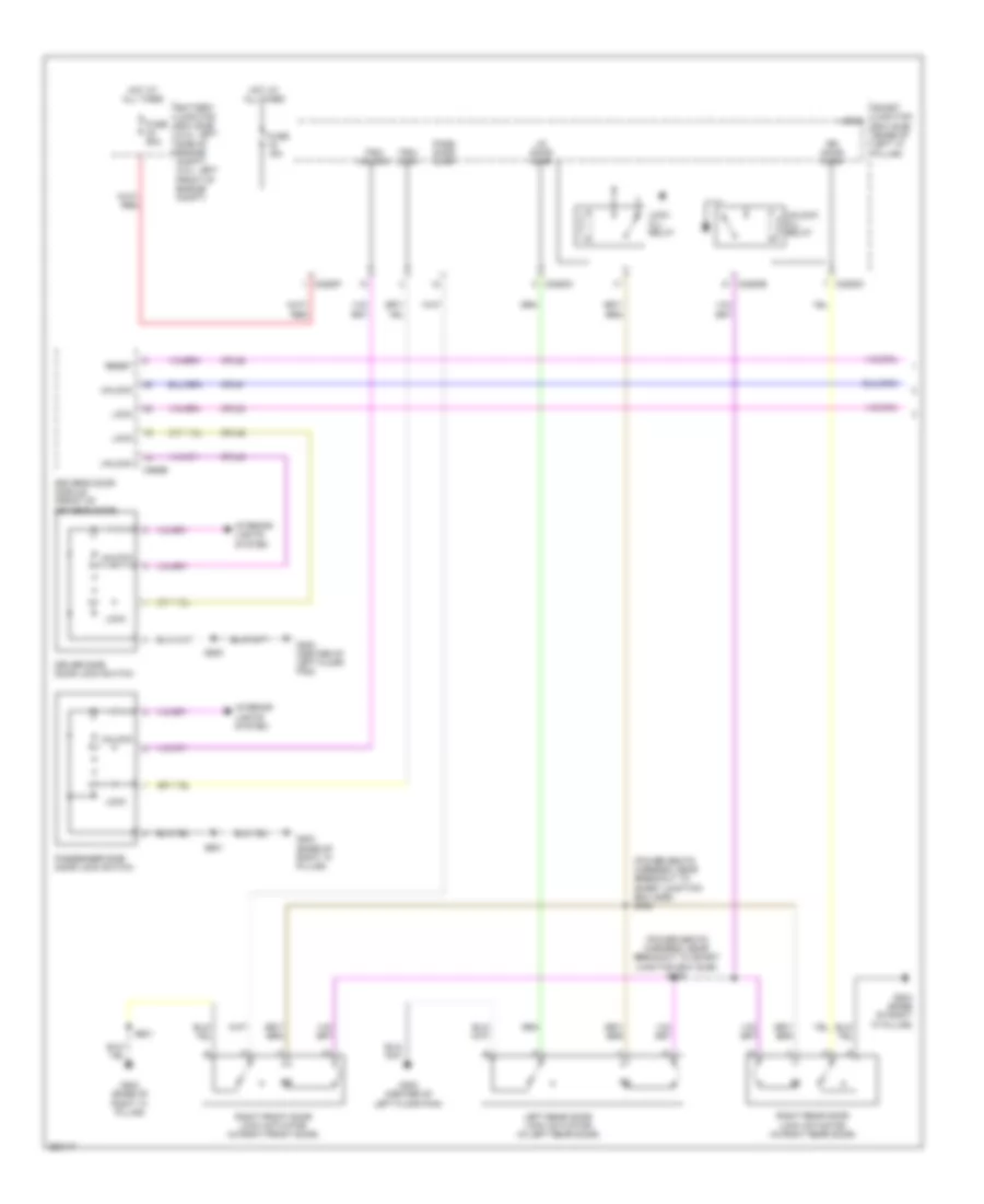
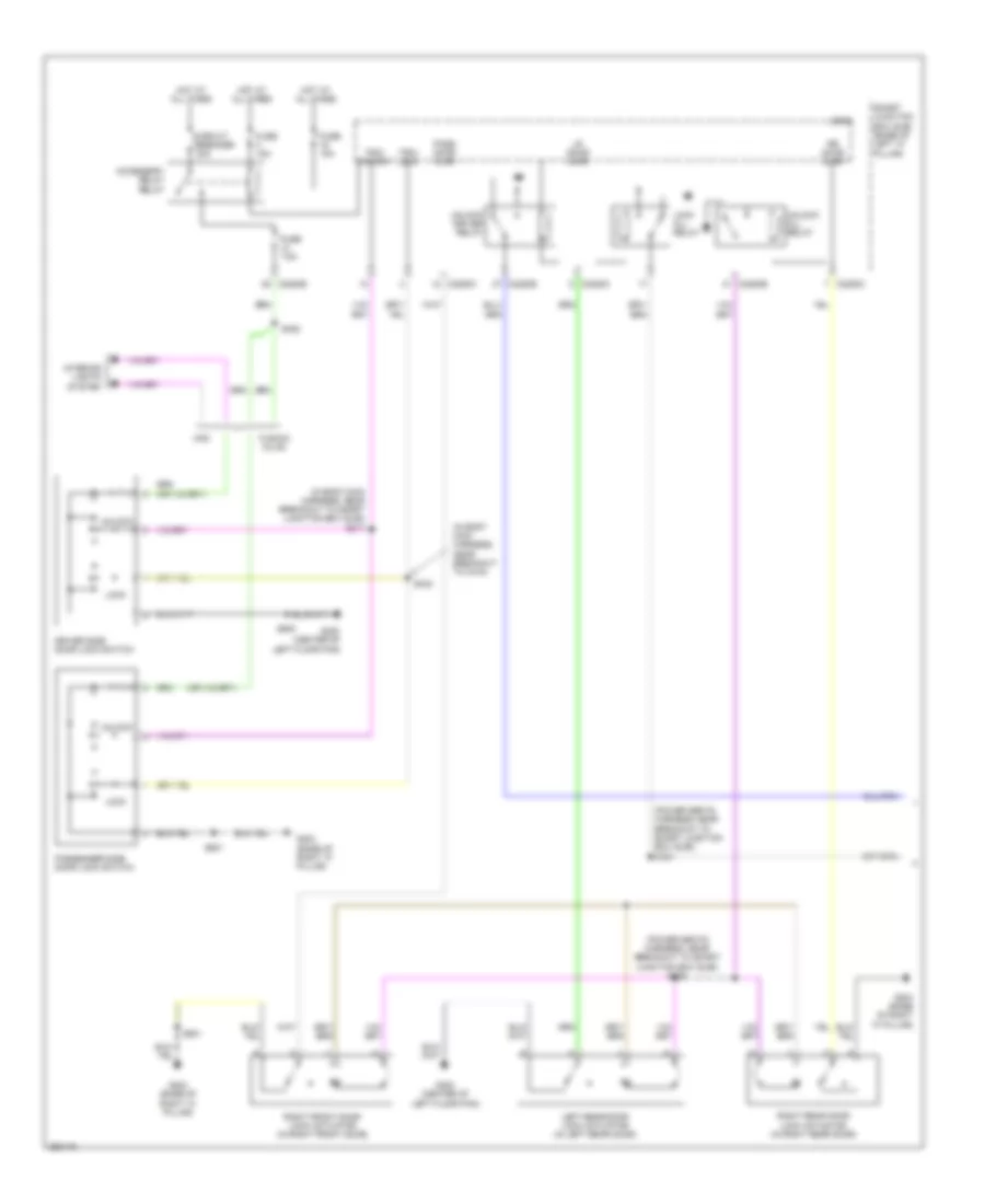
Forced Entry Wiring Diagram, without Memory (1 of 2) for Ford Fusion S 2007
 https://portal-diagnostov.com/license.html
Automotive Electricians Portal FZCO
Automotive Electricians Portal FZCO
https://portal-diagnostov.com/license.html
https://portal-diagnostov.com/license.html
Automotive Electricians Portal FZCO
Automotive Electricians Portal FZCOList of elements for Forced Entry Wiring Diagram, without Memory (1 of 2) for Ford Fusion S 2007:
- (in body main harness, near breakout to c316)
- (in body main harness, near breakout to smart junction box (sjb)) s347
- (power seats harness, near breakout to smart junction box (sjb)) s324
- (power seats harness, near breakout to smart junction box (sjb)) s325
- Accessory delay relay
- C2280c
- C2280e
- Circuit breaker 30a
- Driver side door lock switch
- Fuse 15a
- Fuse 7.5a
- Fusion/ milan
- G203 (base of right "a" pillar)
- G300 (center of left floor pan)
- Hot at all times
- Interior lights system
- Left rear door lock actuator (in left rear door)
- Lock
- Lock all relay
- Logic
- Lr door ajar
- Mkz
- Pass door ajar
- Passenger side door lock switch
- Right front door lock actuator (in right front door)
- Right rear door lock actuator (in right rear door)
- Rr door ajar
- S328
- S342
- S500
- S601
- Smart junction box (sjb) (base of left "a" pillar)
- Trim lock
- Trim unlock
- Unlock
- Unlock all relay
- Unlock driver relay
Forced Entry Wiring Diagram, without Memory (2 of 2) for Ford Fusion S 2007
 https://portal-diagnostov.com/license.html
Automotive Electricians Portal FZCO
Automotive Electricians Portal FZCO
https://portal-diagnostov.com/license.html
https://portal-diagnostov.com/license.html
Automotive Electricians Portal FZCO
Automotive Electricians Portal FZCOList of elements for Forced Entry Wiring Diagram, without Memory (2 of 2) for Ford Fusion S 2007:
- Anti-theft hood switch (except 3.5l: left front radiator support) (3.5l: left front of engine compt)
- C2280a
- C2280c
- Disarm request
- Door reset sw
- Driver door ajar
- G104 (2.3l: in front of right strut tower) (3.0l: right front of engine compt) (3.5l: right side of engine compt)
- G300 (center of left floor pan)
- G400 (center rear of trunk compartment)
- Hood ajar
- Keypad a
- Keypad b
- Keypad c
- Keypad illum
- Keypad switch assembly
- Left front door lock actuator
- Logic
- Luggage compartment disarm switch (2.3l, 3.0l: center rear of luggage compartment)
- Reset
- S500
- Set
- Smart junction box (sjb) (base of left "a" pillar)
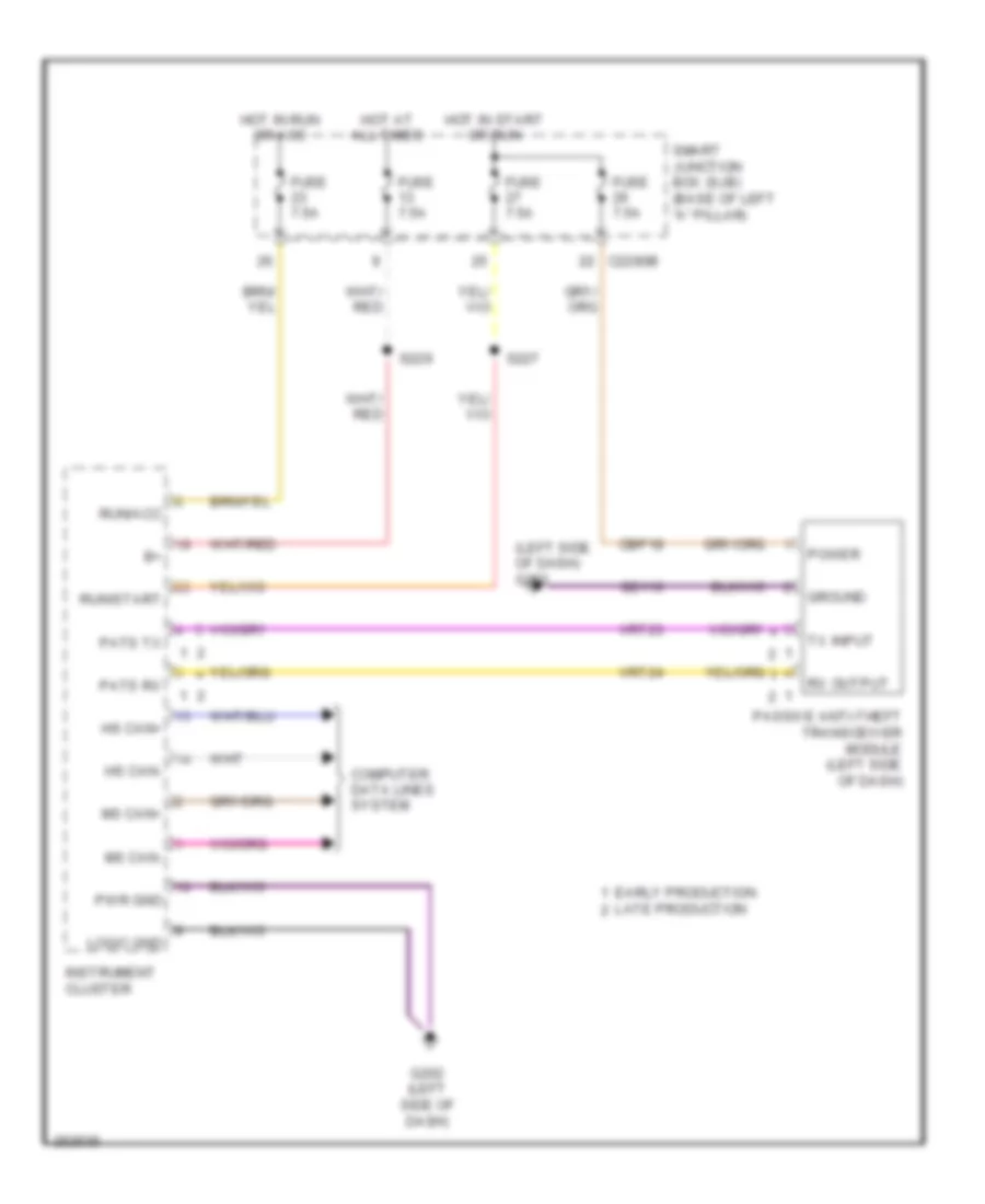
Passive Anti-theft Wiring Diagram for Ford Fusion S 2007
 https://portal-diagnostov.com/license.html
Automotive Electricians Portal FZCO
Automotive Electricians Portal FZCO
https://portal-diagnostov.com/license.html
https://portal-diagnostov.com/license.html
Automotive Electricians Portal FZCO
Automotive Electricians Portal FZCOList of elements for Passive Anti-theft Wiring Diagram for Ford Fusion S 2007:
- (left side of dash) g202
- C2280b
- Cbp18
- Computer data lines system
- Early production
- Fuse 7.5a
- G202 (left side of dash)
- Gd116
- Ground
- Hot at all times
- Hot in run or acc
- Hot in start or run
- Hs can+
- Hs can-
- Instrument cluster
- Late production
- Logic gnd
- Ms can+
- Ms can-
- Passive anti-theft transceiver module (left side of dash)
- Pats rx
- Pats tx
- Power
- Pwr gnd
- Run/acc
- Run/start
- Rx output
- S227
- S229
- Smart junction box (sjb) (base of left "a" pillar)
- Tx input
- Vrt23
- Vrt24
BODY CONTROL MODULES
Body Control Modules Wiring Diagram (1 of 2) for Ford Fusion S 2007
 https://portal-diagnostov.com/license.html
Automotive Electricians Portal FZCO
Automotive Electricians Portal FZCO
https://portal-diagnostov.com/license.html
https://portal-diagnostov.com/license.html
Automotive Electricians Portal FZCO
Automotive Electricians Portal FZCOList of elements for Body Control Modules Wiring Diagram (1 of 2) for Ford Fusion S 2007:
- Acc
- Acc delay relay out
- Anti-lock brakes system
- Anti-theft system
- Battery junction box (bjb) (3.ol: left front of engine compartment) (except 3.0l: left side of engine compartment)
- Bpp sw sig
- Brk fl level sw sig
- C2280a
- C2280b
- Cbp02
- Cbp05
- Cbp08
- Cbp13
- Cbp18
- Cbp19
- Cbp20
- Cbp21
- Cbp23
- Cbp24
- Ccb08
- Cdc12
- Cdc25
- Cdc33
- Cdc34
- Cdc35
- Clf04
- Clf05
- Clf29
- Cls08
- Cls21
- Cls25
- Cmc19
- Cmc24
- Computer data lines system
- Cpl25
- Crh02
- Crw03
- Crw09
- Crw14
- Crw15
- Crw16
- Engine controls & exterior lights systems
- Engine controls & sound systems
- Engine controls & transmissions systems
- Exterior lights system
- Exterior power lamps
- Front fog command
- Fuse 40a
- Headlights system
- High beam lamp feed
- Hood ajar
- Horn relay output
- Horn sw
- Horns system
- Hot at all times
- Ignition switch
- Instrument cluster & air conditioning systems
- Instrument cluster system
- Left lo beam
- Left turn
- Lock
- Off
- Oil pressure ind
- Right lo beam
- Right turn
- Rrw24
- Sbb06
- Sbb19
- Sbp04
- Sbp07
- Sbp11
- Smart junction box (sjb) (base of left ``a" pillar)
- Sound systems
- Start
- Starter relay control
- Starter relay sw output
- Starting/charging system
- Volt in run or acc
- Volt sply at all times
- Volt sply in start
- Volt sply in start & run
- Washer pump relay
- Wiper mtr hi
- Wiper mtr lo
- Wiper park
- Wiper run/park coil
- Wiper run/park relay
- Wiper/washer & air conditioning systems
- Wiper/washer system
Body Control Modules Wiring Diagram (2 of 2) for Ford Fusion S 2007
 https://portal-diagnostov.com/license.html
Automotive Electricians Portal FZCO
Automotive Electricians Portal FZCO
https://portal-diagnostov.com/license.html
https://portal-diagnostov.com/license.html
Automotive Electricians Portal FZCO
Automotive Electricians Portal FZCOList of elements for Body Control Modules Wiring Diagram (2 of 2) for Ford Fusion S 2007:
- (center of left floor pan) g300
- Accessory delay relay out
- Anti-theft & door locks systems
- Anti-theft system
- Autolamp on
- Autolamp sensor
- Battery junction box (bjb) (3.ol: left front of engine compartment) (except 3.0l: left side of engine compartment)
- Bsi sol cmd
- C2280c
- C2280d
- C2280e
- C2280f
- Cbp02
- Cbp06
- Cbp08
- Cbp12
- Cbp16
- Cbp19
- Cbp24
- Ccb09
- Ch122
- Clf17
- Clf18
- Clf19
- Clf21
- Clf23
- Clf27
- Clf28
- Cln04
- Cln09
- Cln26
- Cln27
- Cln28
- Cls17
- Cls18
- Cls19
- Cls32
- Cls34
- Cls38
- Cls39
- Cls41
- Computer data lines system
- Courtesy lighting
- Cpk28
- Cpk29
- Cpk30
- Cpk31
- Cpl10
- Cpl11
- Cpl14 (or crt14)
- Cpl26
- Cpl28
- Cpl31
- Cpl36
- Cpl39
- Cpl42
- Cpl43
- Cpl44
- Cpl45
- Cpl51
- Cpl52
- Cpw01
- Cpw30
- Crw07
- Crw08
- Crw17
- Crw18
- Crw19
- Decklid ajar sw
- Decklid release relay
- Decklid release sw
- Defogger system
- Defrost request
- Defrost rly switched output
- Demand lighting
- Disarm request
- Dome demand
- Door all lock sig
- Door all unlock sig
- Door lock
- Door locks system
- Door reset sw
- Door unlock
- Driver door all lock sig
- Exterior lights system
- Exterior power lamps
- Flash to pass
- Fog indicator
- Fog lamps on
- Fuse 60a
- G202 (left side of dash)
- Gd116
- Gd126
- Go cmd
- Hazard on
- Head parklamp off
- Headlamps on sig
- Headlights system
- High beam req
- Hot at all times
- Instrument cluster & seats systems
- Instrument cluster system
- Interior lights system
- Keypad a
- Keypad b
- Keypad c
- Keypad illum
- Lf door ajar
- Logic gnd
- Lr door ajar
- Mfs code a
- Mfs code b
- Mfs code c
- Mfs h line
- Mfs w line
- Mirrors & sound systems
- Ms can+
- Ms can-
- Panel dimming
- Park brake sw
- Park lamps on
- Power distribution system
- Power gnd
- Power windows & power tops systems
- Power windows system
- Power windows, door locks & mirrors systems
- Pwr illum
- Rear turn sig
- Red
- Rf door ajar
- Rr door ajar
- Sbb01
- Sbb23 (or sbb02)
- Sbp09
- Sbp15
- Shift interlock system
- Sig rtn
- Smart junction box (sjb) (base of left ``a" pillar)
- Sound systems
- Stoplamp feed
- Trunk, tailgate, fuel doors system
- Turn signal lt
- Turn signal rt
- Vdb06
- Vdb07
- Vet13
- Vlf14
- Vln04
- Vln18
- Volt sply at all times
- Volt sply in start & run
- Voltage sply in reverse
- Wiper/washer system
COMPUTER DATA LINES
Computer Data Lines Wiring Diagram, with Memory for Ford Fusion S 2007
 https://portal-diagnostov.com/license.html
Automotive Electricians Portal FZCO
Automotive Electricians Portal FZCO
https://portal-diagnostov.com/license.html
https://portal-diagnostov.com/license.html
Automotive Electricians Portal FZCO
Automotive Electricians Portal FZCOList of elements for Computer Data Lines Wiring Diagram, with Memory for Ford Fusion S 2007:
- (3.5l: near breakout to ambient air temperature sensor) (2.3l & 3.0l: near breakout to front impact severity sensor) s138
- (in body main harness) s331
- (in body main harness, near breakout to c316) s343
- (in body main harness, near breakout to digital signal processing (dsp) module) s414
- (in body main harness, near breakout to g301) s334
- (in body main harness, near breakout to g301) s346
- (in body main harness, near breakout to satellite radio receiver) s430
- (in dash panel to headlamp junction harness, near breakout to powertrain control module (pcm))
- (in dash panel to headlamp junction harness, near engine bulkhead grommet)
- (in main harness) s223
- (in main harness, near breakout to c212) s220
- (left side of dash) g202
- (not used)
- 2.3l
- 6 speed transmission
- Abs control module (right front of engine compartment)
- All wheel drive control module (left kick panel)
- Audio unit (center of dash)
- Base audio/ audio- phile
- Breakout to satellite radio receiver) s431
- C133
- C175b
- C2280b
- C2280d
- C2352b
- C290c
- C310b
- C3305c
- Cdb08
- Data link connector (dlc) (left side of dash)
- Driver seat module
- Driver's door module (front of driver's door)
- Dual automatic temperature control (datc) module (center of dash)
- Electronic automatic temperature control (eatc) module (center of dash)
- Except 2.3l
- Feps
- Fnr5 transmission
- Fuse 20a
- Gd116
- Heated/cooled seat module (under seat bottom)
- Hot at all times
- Hs can+
- Hs can-
- Instrument cluster
- Ms can+
- Ms can-
- Ms can- c228a
- Ms can- c2356a
- Ms can- c240c
- Ms can- c3299c
- Ms can- c4330c
- Ms can- c568a
- Occupant classification sensor (ocs) (in seat cushion)
- Powertrain control module (pcm) (left rear of engine compt)
- Pwr gnd
- Restraints control module (rcm) (under center console)
- S105 (in engine control sensor & fuel charge harness)
- S106
- S122
- S123
- S137 (3.5l: near breakout to abs control module) (2.3l & 3.0l: near breakout to c177)
- S221 (in main harness, near breakout to c212)
- S222 (in main harness)
- S224 (in main harness, near breakout to g200)
- S225 (in main harness)
- S231
- S332 (in body main harness)
- S333 (in body main harness, near breakout to c312)
- S342 (in body main harness, near breakout to c316)
- S345 (in body main harness, near breakout to g301)
- S350 (left kick panel)
- S351 (left kick panel)
- S413 (in body main harness, near breakout to digital signal processing (dsp) module)
- Satellite radio receiver (w/ satellite radio) (right rear of trunk)
- Sbp11
- Sig gnd
- Smart junction box (sjb) (base of left "a" pillar)
- Thx amplifier (with thx) (mkz: right rear of trunk)
- Thx audio/ navi- gation
- Vdb04
- Vdb05
- Vdb06
- Vdb07
Computer Data Lines Wiring Diagram, without Memory for Ford Fusion S 2007
 https://portal-diagnostov.com/license.html
Automotive Electricians Portal FZCO
Automotive Electricians Portal FZCO
https://portal-diagnostov.com/license.html
https://portal-diagnostov.com/license.html
Automotive Electricians Portal FZCO
Automotive Electricians Portal FZCOList of elements for Computer Data Lines Wiring Diagram, without Memory for Ford Fusion S 2007:
- (3.5l: near breakout to ambient air temperature sensor) (2.3l & 3.0l: near breakout to front impact severity sensor) s138
- (in body main harness) s331
- (in body main harness, near breakout to digital signal processing (dsp) module) s414
- (in body main harness, near breakout to g301) s334
- (in body main harness, near breakout to g301) s345
- (in body main harness, near breakout to g301) s346
- (in dash panel to headlamp junction harness, near breakout to powertrain control module (pcm))
- (in dash panel to headlamp junction harness, near engine bulkhead grommet)
- (in main harness)
- (in main harness, near breakout to c212) s220
- (left side of dash) g202
- (not used)
- 2.3l
- 6 speed transmission
- Abs control module (right front of engine compartment)
- All wheel drive control module (left kick panel)
- Audio unit (center of dash)
- Base audio/ audio- phile
- C133
- C175b
- C2280b
- C2280d
- C2352b
- C290c
- C310b
- C3305c
- Cdb08
- Data link connector (dlc) (left side of dash)
- Dual automatic temperature control (datc) module (center of dash)
- Electronic automatic temperature control (eatc) module (center of dash)
- Except 2.3l
- Feps
- Fnr5 transmission
- Fuse 20a
- Fusion/ milan
- Gd116
- Heated/cooled seat module (under seat bottom)
- Hot at all times
- Hs can+
- Hs can-
- Instrument cluster
- Mkz
- Ms can+
- Ms can-
- Ms can- c228a
- Ms can- c2356a
- Ms can- c240c
- Ms can- c4330c
- Occupant classification sensor (ocs) (in seat cushion)
- Powertrain control module (pcm) (left rear of engine compt)
- Pwr gnd
- Restraints control module (rcm) (under center console)
- S105 (in engine control sensor & fuel charge harness)
- S106
- S122
- S123
- S137 (3.5l: near breakout to abs control module) (2.3l & 3.0l: near breakout to c177)
- S221 (in main harness, near breakout to c212)
- S222 (in main harness)
- S223
- S224 (in main harness, near breakout to g200)
- S225 (in main harness)
- S231
- S332 (in body main harness)
- S333 (in body main harness, near breakout to c312)
- S350 (left kick panel)
- S351 (left kick panel)
- S413 (in body main harness, near breakout to digital signal processing (dsp) module)
- S430 (in body main harness, near breakout to satellite radio receiver)
- S431 (in body main harness, near breakout to satellite radio receiver)
- Satellite radio receiver (w/ satellite radio) (right rear of trunk)
- Sbp11
- Sig gnd
- Smart junction box (sjb) (base of left ``a" pillar)
- Thx amplifier (w/ thx) (right rear of trunk)
- Thx audio/ navi- gation
- Vdb04
- Vdb05
- Vdb06
- Vdb07
COOLING FAN
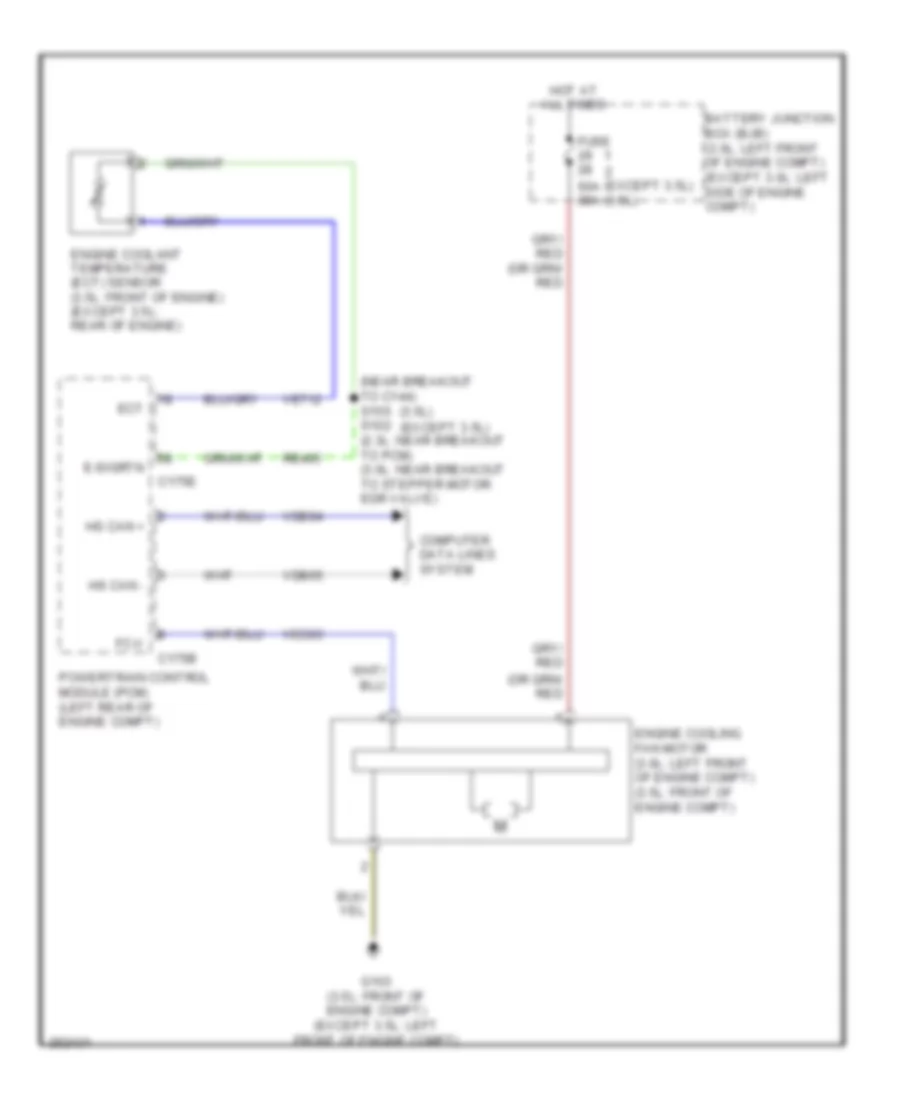
Cooling Fan Wiring Diagram for Ford Fusion S 2007
 https://portal-diagnostov.com/license.html
Automotive Electricians Portal FZCO
Automotive Electricians Portal FZCO
https://portal-diagnostov.com/license.html
https://portal-diagnostov.com/license.html
Automotive Electricians Portal FZCO
Automotive Electricians Portal FZCOList of elements for Cooling Fan Wiring Diagram for Ford Fusion S 2007:
- (3.5l)
- (except 3.5l)
- (except 3.5l) (3.5l)
- (near breakout to c144) s155 s102 (2.3l: near breakout to pcm) (3.0l: near breakout to stepper motor egr valve)
- 60a 80a
- Battery junction box (bjb) (3.0l: left front of engine compt) (except 3.0l: left side of engine compt)
- C175b
- C175e
- Computer data lines system
- E-sigrtn
- Ect
- Engine coolant temperature (ect) sensor (3.5l: front of engine) (except 3.5l: rear of engine)
- Engine cooling fan motor (3.0l: left front of engine compt) (3.5l: front of engine compt)
- Fc-v
- Fuse
- G103 (3.5l: front of engine compt) (except 3.5l: left front of engine compt)
- Hot at all times
- Hs can +
- Hs can -
- Powertrain control module (pcm) (left rear of engine compt)
- Re405
- Vdb04
- Vdb05
- Ve712
- Vec03
CRUISE CONTROL
Cruise Control Wiring Diagram for Ford Fusion S 2007
 https://portal-diagnostov.com/license.html
Automotive Electricians Portal FZCO
Automotive Electricians Portal FZCO
https://portal-diagnostov.com/license.html
https://portal-diagnostov.com/license.html
Automotive Electricians Portal FZCO
Automotive Electricians Portal FZCOList of elements for Cruise Control Wiring Diagram for Ford Fusion S 2007:
- (2.3l, 3.0l:
- (3.5l: near breakout to powertrain control module) (3.0l: near breakout to g103) (2.3l: near breakout to left front side lamp)
- (left rear of engine) electronic throttle control (etc) motor
- 2.3l
- 3.0l
- 3.5l
- Accelerator pedal position sensor (left side of dash)
- Air bag sliding contact (behind steering wheel assembly)
- Air conditioning system
- App1
- App2
- App3
- Appsref1
- Appsref2
- Appsrtn1
- Appsrtn2
- Battery junction box (bjb) (3.0l: left front of engine compartment) (except 3.0l: left side of engine compartment)
- Boo
- Boo input
- Bps
- Brake pedal position switch (left side of dash)
- C175b
- C175e
- C218a
- C218b
- C2280a
- Casegnd
- Cbp18
- Cbp42 (or cbp47)
- Ccb08
- Ce412
- Ce426
- Ces09
- Computer data lines system
- Early production
- Fan+
- Fan-
- Fuse 10a
- Fuse 15a
- Fuse 7.5a
- G102 (left rear of engine compt)
- G202 (left side of dash)
- G204 (behind air bag, in steering wheel)
- Gd120
- Hot at all times
- Hot in start or run
- Hot w/ pcm power relay energized
- Hs can +
- Hs can -
- Ignition
- Interior lights system
- Kapwr
- Late production
- Le136
- Le137
- Le428
- Left steering wheel switch
- Near engine bulkhead grommet) s120
- Off
- Powertrain control module (pcm) (left rear of engine compt)
- Pwrgnd1
- Pwrgnd2
- Pwrgnd3
- Re136
- Re137
- Re427
- Res08
- Rsm
- S119
- S121
- S127
- S129 s142
- S132
- S133
- S203 (in steering wheel jumper harness)
- Sbb23
- Sbp07
- Sccs
- Sccsrtn
- Set +
- Set-
- Smart junction box (sjb) (base of left "a" pillar)
- Tacm+
- Tacm-
- Tp1 ns
- Tp2 ps
- Tpref
- Tprtn
- Vdb04
- Vdb05
- Ve701
- Ve702
- Ve703
- Ve818
- Ve819
- Ves10
- Vpwr1
- W/ climate control switch
DEFOGGERS
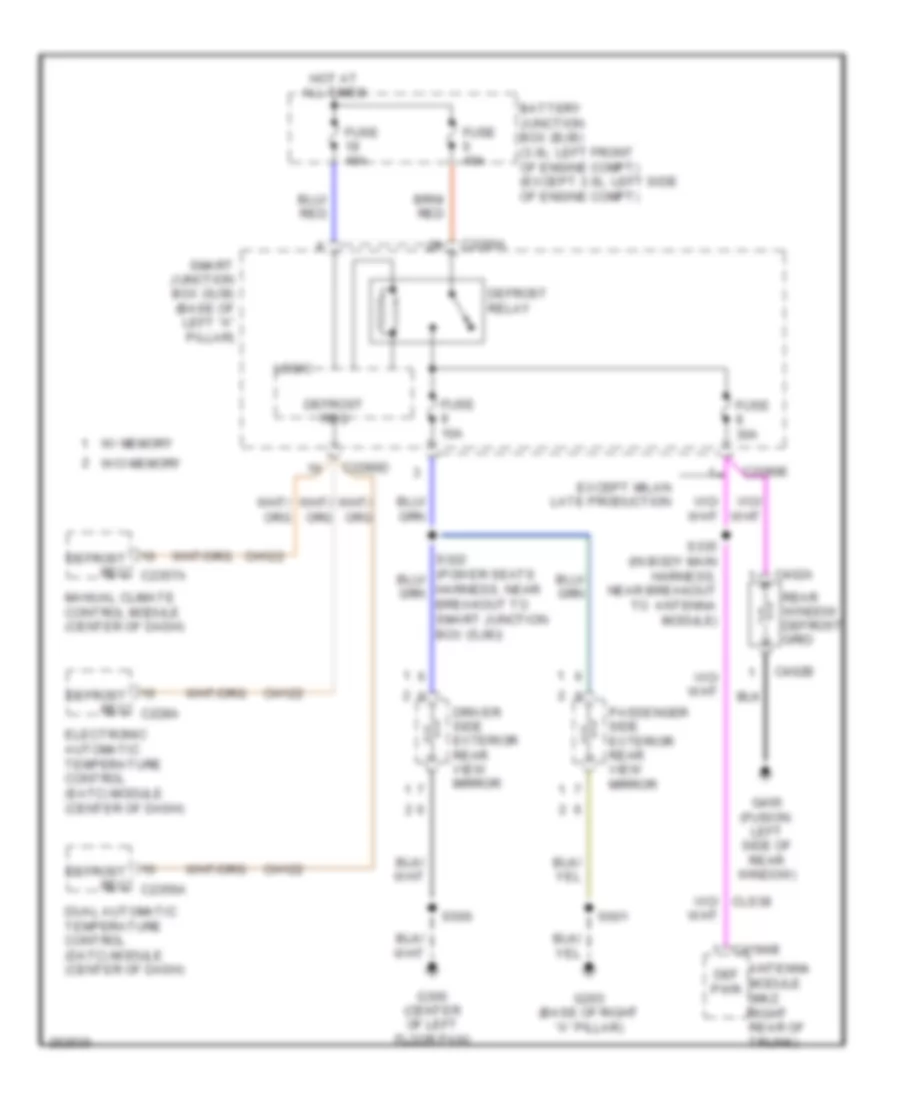
Defoggers Wiring Diagram for Ford Fusion S 2007
 https://portal-diagnostov.com/license.html
Automotive Electricians Portal FZCO
Automotive Electricians Portal FZCO
https://portal-diagnostov.com/license.html
https://portal-diagnostov.com/license.html
Automotive Electricians Portal FZCO
Automotive Electricians Portal FZCOList of elements for Defoggers Wiring Diagram for Ford Fusion S 2007:
- Antenna module (mkz: right rear of trunk)
- Battery junction box (bjb) (3.0l: left front of engine compt) (except 3.0l: left side of engine compt)
- Breakout to smart junction box (sjb))
- C2280a
- C2280d
- C2280e
- C402a
- C402b
- C4194b
- Ch122
- Def pwr
- Defrost relay
- Defrost req
- Defrost req c228a
- Defrost req c2356a
- Defrost req c2357a
- Driver side exterior rear view mirror
- Dual automatic temperature control (datc) module (center of dash)
- Electronic automatic temperature control (eatc) module (center of dash)
- Except milan late production
- Fuse 10a
- Fuse 30a
- Fuse 40a
- G203 (base of right "a" pillar)
- G300 (center of left floor pan)
- G405 (fusion: left side of rear window)
- Hot at all times
- Logic
- Manual climate control module (center of dash)
- Passenger side exterior rear view mirror
- Rear window defrost grid
- S335 (in body main harness, near breakout to antenna module)
- S500
- S601
- Smart junction box (sjb) (base of left "a" pillar)
- W/ memory
- W/o memory
ENGINE PERFORMANCE
2.3L
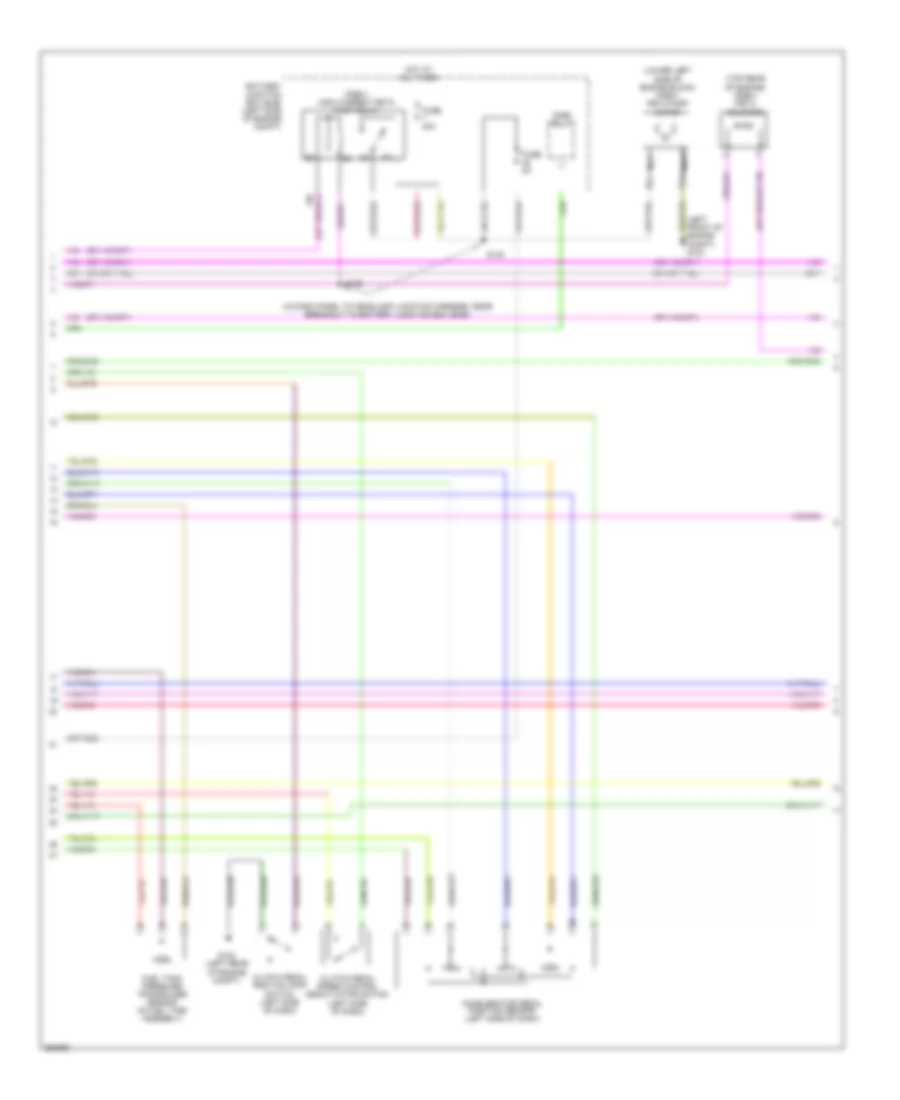
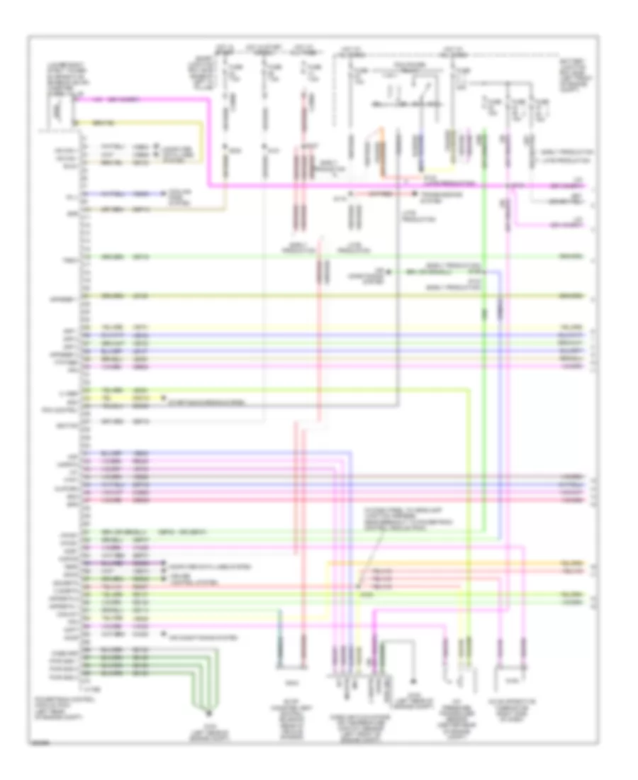
2.3L, Engine Performance Wiring Diagram (1 of 5) for Ford Fusion S 2007
 https://portal-diagnostov.com/license.html
Automotive Electricians Portal FZCO
Automotive Electricians Portal FZCO
https://portal-diagnostov.com/license.html
https://portal-diagnostov.com/license.html
Automotive Electricians Portal FZCO
Automotive Electricians Portal FZCOList of elements for 2.3L, Engine Performance Wiring Diagram (1 of 5) for Ford Fusion S 2007:
- (in dash panel to headlamp junction harness, near breakout to powertrain control
- A/c evaporative thermistor (right side of dash)
- A/c pressure transducer sensor (right front of engine)
- Accr
- Acet
- Acpt
- Air conditioning system
- App 1
- App 2
- App 3
- Appsref 1
- Appsref 2
- Appsrtn 1
- Appsrtn 2
- Battery junction box (bjb) (left side of engine compt)
- Boo
- Bps
- C sigrtn
- C vref
- C175b
- C2280a
- Canvnt
- Case gnd
- Cbp18
- Cbp42
- Cbp46
- Ccb08
- Cdb08
- Cdc12
- Ce114
- Ce132
- Ce302
- Ce404
- Ce608
- Ce903
- Ce904
- Ces09
- Cet40
- Ch302
- Computer data lines system
- Cooling fans system
- Cpp bt
- Cpp tt
- Cruise control system
- Eair
- Eairm
- Early production
- Evap canister vent control solenoid (rear of vehicle chassis)
- Evaporative emission (evap) canister purge valve (lower right strut tower)
- Evmv
- Fc v
- Feps
- Fpc
- Fpm
- Ftpt
- Ftptref
- Fuse 15a
- Fuse 40a
- Fuse 7.5a
- G102 (left rear of engine compt)
- Gd120
- Hot at all times
- Hot in start or run
- Hs can +
- Hs can -
- Iat
- Ignition
- Injpwrm
- Kapwr
- Late production
- Le136
- Le137
- Le230
- Le424
- Maf
- Mafrtn
- Mass air flow/intake air temperature (maf/iat) sensor (left front of engine compt)
- Module (pcm))
- Output shaft speed (oss) sensor (top of transmission)
- Pcm control
- Pcm power relay
- Powertrain control module (pcm) (left rear of engine compt)
- Pwr gnd
- Pwr gnd 1
- Pwr gnd 2
- Pwr gnd 3
- Re136
- Re137
- Re325
- Re407
- Res08
- S121
- S124
- S127
- S129
- S143 (late production)
- S144
- Sbb45
- Sbp07
- Sccs
- Sccsrtn
- Smart junction box (sjb) (base of left "a" pillar)
- Smc
- Starting/charging system
- Trsw
- Vdb04
- Vdb05
- Ve225
- Ve701
- Ve702
- Ve703
- Ve740
- Ve806
- Ve808
- Ve922
- Vec03
- Ves10
- Vh406
- Vh433
- Vpwr
- Vpwr1
- Vssin
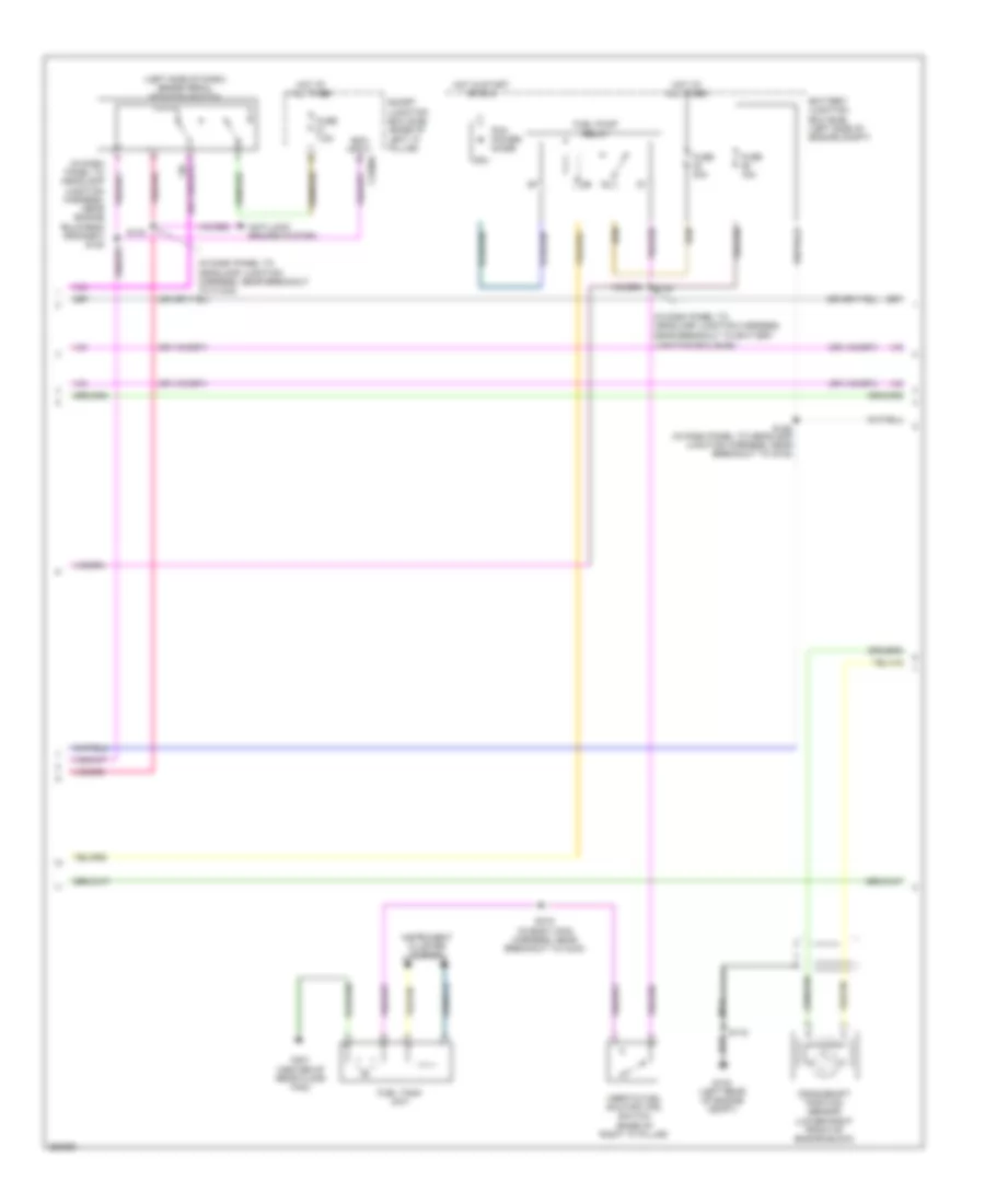
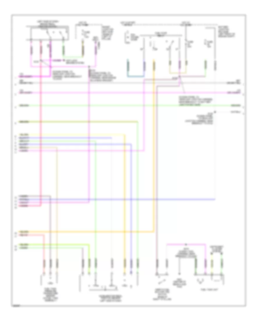
2.3L, Engine Performance Wiring Diagram (2 of 5) for Ford Fusion S 2007
 https://portal-diagnostov.com/license.html
Automotive Electricians Portal FZCO
Automotive Electricians Portal FZCO
https://portal-diagnostov.com/license.html
https://portal-diagnostov.com/license.html
Automotive Electricians Portal FZCO
Automotive Electricians Portal FZCOList of elements for 2.3L, Engine Performance Wiring Diagram (2 of 5) for Ford Fusion S 2007:
- (in dash panel to headlamp junction harness, near breakout to battery junction box (bjb))
- (left front of engine compt) g103
- (lower left side of engine block) (pzev) peta pump motor
- (pzev) high current peta pump relay
- (top rear of engine) (pzev) peta solenoid
- Accelerator pedal position sensor (left side of dash)
- Battery junction box (bjb) (left side of engine compt)
- Clutch pedal position (cpp) switch (left side of dash)
- Clutch pedal speed control deactivator switch (left side of dash)
- Fnr5 relay
- Fuel tank pressure transducer sensor (in fuel tank assembly)
- Fuse 40a
- Fuse 5a
- G102 (left rear of engine compt)
- Hot at all times
- Nca
- S139
- S140
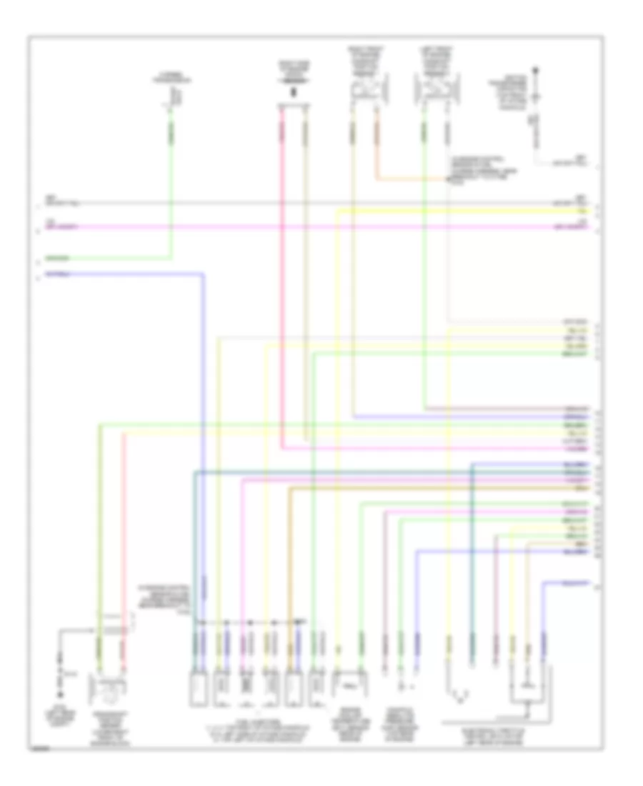
2.3L, Engine Performance Wiring Diagram (3 of 5) for Ford Fusion S 2007
 https://portal-diagnostov.com/license.html
Automotive Electricians Portal FZCO
Automotive Electricians Portal FZCO
https://portal-diagnostov.com/license.html
https://portal-diagnostov.com/license.html
Automotive Electricians Portal FZCO
Automotive Electricians Portal FZCOList of elements for 2.3L, Engine Performance Wiring Diagram (3 of 5) for Ford Fusion S 2007:
- (in dash panel to headlamp junction harness, near breakout to battery
- (in dash panel to headlamp junction harness, near breakout to c1443)
- (in dash panel to headlamp junction harness, near engine bulkhead grommet) s120
- (left side of dash) brake pedal position switch
- Anti-lock brakes system
- Battery junction box (bjb) (left side of engine compt)
- Boo input c2280a
- Crankshaft position sensor (lower right front of engine block)
- Fuel pump relay
- Fuel tank unit
- Fuse 15a
- Fuse 30a
- Fuse 7.5a
- G102 (left rear of engine compt)
- G401 (center of rear floor pan)
- Hot at all times
- Hot in start or run
- Inertia fuel shutoff (ifs) switch (base of right "a" pillar)
- Instrument cluster system
- Junction box (bjb))
- Nca
- Pcm power diode
- S115
- S125 (in dash panel to headlamp junction harness, near breakout to g102)
- S130
- S133
- S415 (in body main harness, near breakout to c433)
- Smart junction box (sjb) (base of left "a" pillar)
2.3L, Engine Performance Wiring Diagram (4 of 5) for Ford Fusion S 2007
 https://portal-diagnostov.com/license.html
Automotive Electricians Portal FZCO
Automotive Electricians Portal FZCO
https://portal-diagnostov.com/license.html
https://portal-diagnostov.com/license.html
Automotive Electricians Portal FZCO
Automotive Electricians Portal FZCOList of elements for 2.3L, Engine Performance Wiring Diagram (4 of 5) for Ford Fusion S 2007:
- (front of engine) knock sensor
- (in engine control sensor & fuel charge harness, near breakout to c1368)
- (in engine control sensor & fuel charge harness, near breakout to c1543) s113
- (left side of dash) transmission range sensor
- (top left of engine) swirl control valve solenoid
- (top rear of engine) cylinder identification sensor
- Electronic throttle control (etc) motor (left rear of engine)
- Engine coolant temperature (ect) sensor (rear of engine)
- Fuel injectors (top of intake manifold)
- Inlet manifold runner control (imrc) module (top of intake manifold)
- Nca
- Park/ neutral
- S108
- Swirl control monitor
- Temperature manifold absolute pressure (tmap) sensor (lower left side of engine block)
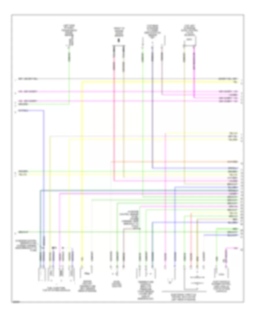
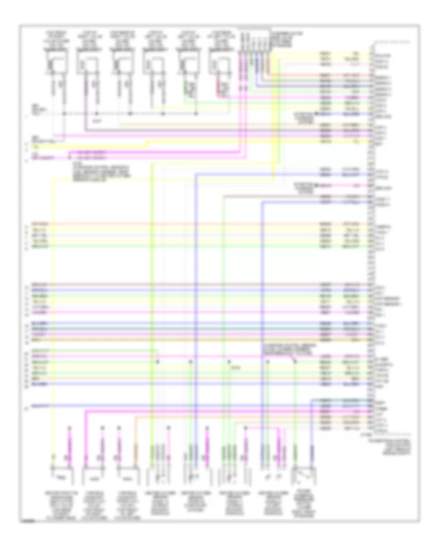
2.3L, Engine Performance Wiring Diagram (5 of 5) for Ford Fusion S 2007
 https://portal-diagnostov.com/license.html
Automotive Electricians Portal FZCO
Automotive Electricians Portal FZCO
https://portal-diagnostov.com/license.html
https://portal-diagnostov.com/license.html
Automotive Electricians Portal FZCO
Automotive Electricians Portal FZCOList of elements for 2.3L, Engine Performance Wiring Diagram (5 of 5) for Ford Fusion S 2007:
- (in engine control sensor & fuel charge harness, near breakout to c175e) s102
- (top rear of left valve cover) coil on plugs (cop)
- Bvpwr
- C175e
- Cdc10
- Cdc15
- Ce102
- Ce103
- Ce104
- Ce205
- Ce206
- Ce207
- Ce208
- Ce233
- Ce234
- Ce235
- Ce301
- Ce303
- Ce304
- Ce305
- Ce306
- Ce316
- Ce411
- Ce412
- Ce421
- Ce426
- Cht
- Cid
- Ckp sensor +
- Ckp sensor -
- Cms 12
- Cms 13
- Cop 1
- Cop 2
- Cop 3
- Cop 4
- Ctrl 1
- Ctrl 2
- Ctrl 3
- Ctrl 4
- Cylinder- head temperature sensor
- E sigrtn
- E vref
- Ect
- Egrmc 1
- Egrmc 2
- Egrmc 3
- Egrmc 4
- Gen com
- Gen mon
- Heated oxygen sensor (ho2s) 11 (in exhaust manifold)
- Heated oxygen sensor (ho2s) 12 (in exhaust manifold)
- Heated oxygen sensor (ho2s) 13 (in exhaust system)
- Ho2s 11
- Htr 11
- Htr 12
- Htr 13
- Ignition transformer capacitor (top front of intake
- Imrc
- Imtv
- Inj 1
- Inj 2
- Inj 3
- Inj 4
- Ks1 +
- Ks1 -
- Le111
- Le423
- Le428
- Manifold)
- Map
- Power steering pressure switch (front of engine)
- Powertrain control module (pcm) (left rear of engine compt)
- Pspt
- Re135
- Re323
- Re405
- Re427
- S107 (in engine control sensor & fuel charge harness, near breakout to c1161)
- S109 (in engine control sensor & fuel charge harness, near breakout to c191)
- Scvm
- Starting/charging system
- Stepper motor egr valve (right rear of engine)
- Tacm +
- Tacm -
- Tp1 ns
- Tp2 ps
- Tpref
- Tprtn
- Variable camshaft timing (vct) valve (top rear of engine)
- Vcs10
- Vct
- Ve519
- Ve706
- Ve711
- Ve712
- Ve716
- Ve731
- Ve733
- Ve735
- Ve801
- Ve803
- Ve818
- Ve819
- Vol supp
- Vol supp vol supp
3.0L
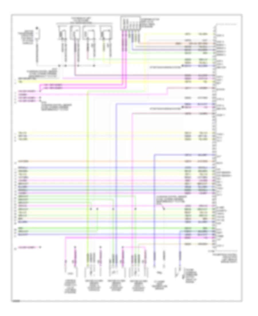
3.0L, Engine Performance Wiring Diagram (1 of 4) for Ford Fusion S 2007
 https://portal-diagnostov.com/license.html
Automotive Electricians Portal FZCO
Automotive Electricians Portal FZCO
https://portal-diagnostov.com/license.html
https://portal-diagnostov.com/license.html
Automotive Electricians Portal FZCO
Automotive Electricians Portal FZCOList of elements for 3.0L, Engine Performance Wiring Diagram (1 of 4) for Ford Fusion S 2007:
- (early production) s129
- (in dash panel to headlamp junction harness, near breakout to powertrain control module (pcm))
- (lower right strut tower) evaporative emission (evap) canister purge valve
- (or cbp47)
- A/c evaporative thermistor (right side of dash)
- A/c pressure transducer sensor (center rear of engine compt)
- Accr
- Acet
- Acpt
- Air conditioning system
- App 1
- App 2
- App 3
- Appsref 1
- Appsref 2
- Appsrtn 1
- Appsrtn 2
- Battery junction box (bjb) (left front of engine compt)
- Boo
- Bps
- C sigrtn
- C vref
- C175b
- C2280a
- C2280b
- Canvnt
- Case gnd
- Cbp13
- Cbp18
- Cbp42
- Cbp46
- Cbp47
- Ccb08
- Cdb08
- Cdc12
- Ce114
- Ce132
- Ce302
- Ce608
- Ces09
- Cet40
- Ch302
- Computer data lines system
- Cooling fans system
- Cruise control system
- Early production
- Evap canister vent control solenoid (rear of vehicle chassis)
- Evmv
- Fc v
- Feps
- Fpc
- Fpm
- Ftpt
- Ftptref
- Fuse 10a
- Fuse 15a
- Fuse 40a
- Fuse 7.5a
- G102 (left rear of engine compt)
- Gd120
- Hot at all times
- Hot in start
- Hot in start or run
- Hs can +
- Hs can -
- Iat
- Ignition
- Injpwrm
- Kapwr
- Late production
- Le136
- Le137
- Le230
- Le424
- Maf
- Mafrtn
- Mass air flow/intake air temperature (maf/iat) sensor (left front of engine compt)
- Pcm control
- Pcm power relay
- Powertrain control module (pcm) (left rear of engine compt)
- Pwr gnd
- Pwr gnd 1
- Pwr gnd 2
- Pwr gnd 3
- Re136
- Re137
- Re325
- Re407
- Res08
- S119
- S121
- S124
- S127
- S142 (early production)
- S143 (late production)
- S144
- S232
- Sbp07
- Sccs
- Sccsrtn
- Smart junction box (sjb) (base of left "a" pillar)
- Smc
- Smr
- Starting/charging system
- Transmissions system
- Trsw
- Vdb04
- Vdb05
- Ve225
- Ve701
- Ve702
- Ve703
- Ve740
- Ve808
- Ve922
- Vec03
- Ves10
- Vh406
- Vh433
- Vpwr
- Vpwr1
3.0L, Engine Performance Wiring Diagram (2 of 4) for Ford Fusion S 2007
 https://portal-diagnostov.com/license.html
Automotive Electricians Portal FZCO
Automotive Electricians Portal FZCO
https://portal-diagnostov.com/license.html
https://portal-diagnostov.com/license.html
Automotive Electricians Portal FZCO
Automotive Electricians Portal FZCOList of elements for 3.0L, Engine Performance Wiring Diagram (2 of 4) for Ford Fusion S 2007:
- (in dash panel to headlamp junction harness, near breakout to battery
- (in dash panel to headlamp junction harness, near breakout to g103)
- (left side of dash) brake pedal position switch
- Accelerator pedal position sensor (left side of dash)
- Anti-lock brakes system
- Battery junction box (bjb) (left front of engine compt)
- Boo input c2280a
- Fuel pump relay
- Fuel tank pressure transducer sensor (in fuel tank assembly)
- Fuel tank unit
- Fuse 15a
- Fuse 30a
- Fuse 7.5a
- G401 (center of rear floor pan)
- Hot at all times
- Hot in start or run
- Inertia fuel shutoff (ifs) switch (base of right "a" pillar)
- Instrument cluster system
- Junction box (bjb))
- Pcm power diode
- S125 (in dash panel to headlamp junction harness, near breakout to g102)
- S130
- S133
- S415 (in body main harness, near breakout to c433)
- Smart junction box (sjb) (base of left "a" pillar)
3.0L, Engine Performance Wiring Diagram (3 of 4) for Ford Fusion S 2007
 https://portal-diagnostov.com/license.html
Automotive Electricians Portal FZCO
Automotive Electricians Portal FZCO
https://portal-diagnostov.com/license.html
https://portal-diagnostov.com/license.html
Automotive Electricians Portal FZCO
Automotive Electricians Portal FZCOList of elements for 3.0L, Engine Performance Wiring Diagram (3 of 4) for Ford Fusion S 2007:
- (in engine control sensor & fuel charge harness, near breakout to c175e) s103
- (in engine control sensor & fuel charge harness, near breakout to c181)
- (left front of engine) camshaft position sensor 2
- (right front of engine) camshaft position sensor 1
- (right side of engine) knock sensor
- 6 speed transmission
- Crankshaft position sensor (lower right front of engine block)
- Electronic throttle control (etc) motor (left rear of engine)
- Engine coolant temperature (ect) sensor (rear of engine)
- Fuel injectors (1, 2, 3: top right of intake manifold) (5, 6: left side of intake manifold) (4: top left of intake manifold)
- G102 (left rear of engine compt)
- Ignition transformer capacitor (top front of intake
- Lock start
- Manifold absolute pressure (map) sensor (top rear of engine)
- Manifold)
- Nca
- S108
- S115
3.0L, Engine Performance Wiring Diagram (4 of 4) for Ford Fusion S 2007
 https://portal-diagnostov.com/license.html
Automotive Electricians Portal FZCO
Automotive Electricians Portal FZCO
https://portal-diagnostov.com/license.html
https://portal-diagnostov.com/license.html
Automotive Electricians Portal FZCO
Automotive Electricians Portal FZCOList of elements for 3.0L, Engine Performance Wiring Diagram (4 of 4) for Ford Fusion S 2007:
- (in engine control sensor & fuel charge harness, near breakout to c1450)
- (top front of right valve cover) coil on plugs (cop) 1
- (top of right valve cover) coil on plugs (cop) 2
- (top of left valve cover) coil on plugs (cop) 4
- (top of left valve cover) coil on plugs (cop) 5
- (top rear of right valve cover) coil on plugs (cop) 3
- (top rear of left valve cover) coil on plugs (cop) 6
- C175e
- Cdc10
- Cdc15
- Ce102
- Ce103
- Ce104
- Ce205
- Ce206
- Ce207
- Ce208
- Ce209
- Ce210
- Ce233
- Ce234
- Ce235
- Ce236
- Ce301
- Ce303
- Ce304
- Ce305
- Ce306
- Ce307
- Ce308
- Ce321
- Ce412
- Ce421
- Ce422
- Ce426
- Cid 1
- Cid 2
- Ckp sensor +
- Ckp sensor -
- Cms 12
- Cms 22
- Cop 1
- Cop 2
- Cop 3
- Cop 4
- Cop 5
- Cop 6
- Ctrl 1
- Ctrl 2
- Ctrl 3
- Ctrl 4
- E sigrtn
- E vref
- Ect
- Egrmc 1
- Egrmc 2
- Egrmc 3
- Egrmc 4
- Gen com
- Gen mon
- Heated oxygen sensor (ho2s) 11 (in right exhaust manifold)
- Heated oxygen sensor (ho2s) 12 (in right exhaust manifold)
- Heated oxygen sensor (ho2s) 21 (in left exhaust manifold)
- Heated oxygen sensor (ho2s) 22 (in exhaust system)
- Heated positive crankcase ventilation (pcv) valve (top rear of right cylinder head)
- Ho2s 11
- Ho2s 21
- Htr 11
- Htr 12
- Htr 21
- Htr 22
- Inj 1
- Inj 2
- Inj 3
- Inj 4
- Inj 5
- Inj 6
- Ks1 +
- Ks1 -
- Le423
- Le428
- Map
- Pcvhtr
- Power steering pressure switch (lower right front of engine)
- Powertrain control module (pcm) (left rear of engine compt)
- Pspt
- Re135
- Re323
- Re405
- Re427
- Re429
- S102
- S107
- S149 (in engine control sensor & fuel sensor harness, near breakout to heated oxygen sensor (ho2s) 22)
- Starting/ charging system
- Stepper motor egr valve (top rear of engine)
- Tacm +
- Tacm -
- Tp1 ns
- Tp2 ps
- Tpref
- Tprtn
- Variable camshaft timing (vct) valve 1 (top front of right valve cover)
- Variable camshaft timing (vct) valve 2 (top front of left valve cover)
- Vcs10
- Vct
- Vct 2
- Ve706
- Ve707
- Ve711
- Ve716
- Ve731
- Ve733
- Ve735
- Ve737
- Ve801
- Ve803
- Ve818
- Ve819
- Vol supp
- Vol supp vol supp
- Vrsrtn
EXTERIOR LIGHTS
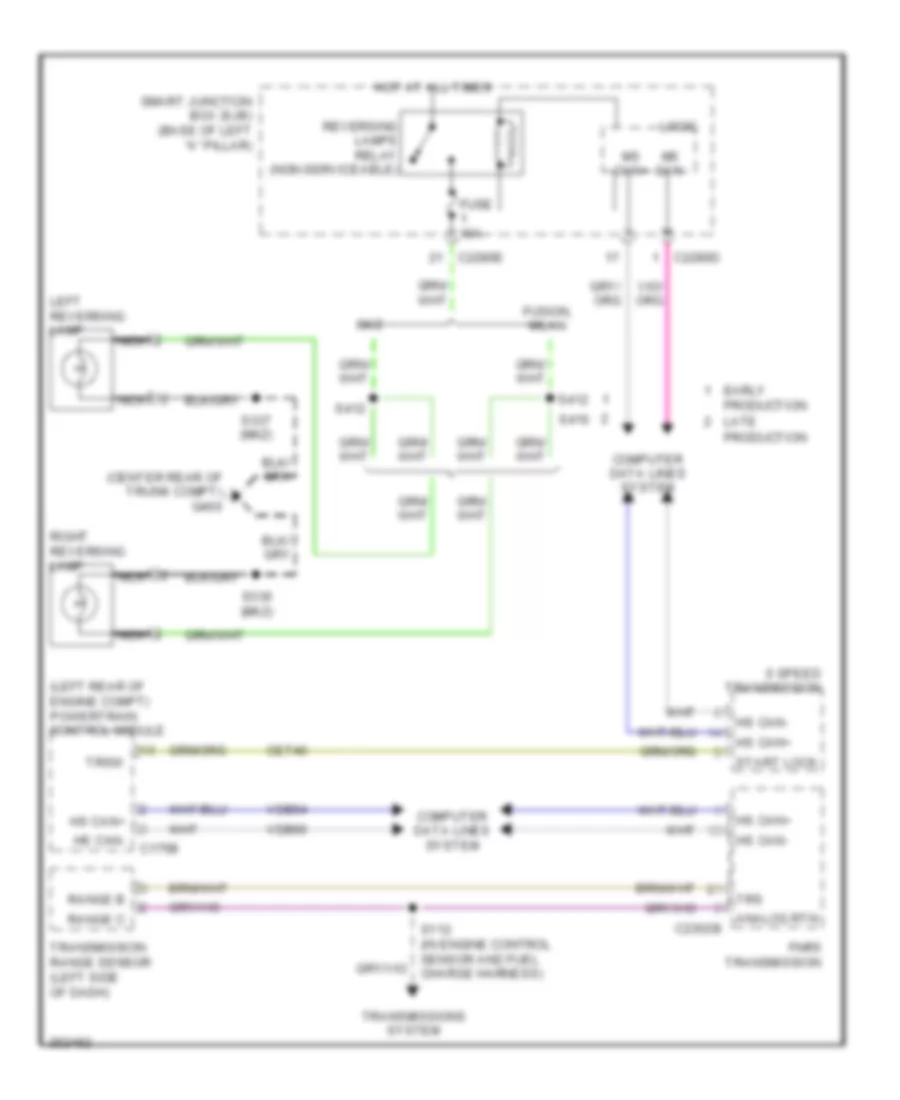
Back-up Lamps Wiring Diagram, A/T for Ford Fusion S 2007
 https://portal-diagnostov.com/license.html
Automotive Electricians Portal FZCO
Automotive Electricians Portal FZCO
https://portal-diagnostov.com/license.html
https://portal-diagnostov.com/license.html
Automotive Electricians Portal FZCO
Automotive Electricians Portal FZCOList of elements for Back-up Lamps Wiring Diagram, A/T for Ford Fusion S 2007:
- (center rear of trunk compt) g400
- (left rear of engine compt) powertrain control module
- 6 speed transmission
- Analog rtn
- C175b
- C2280d
- C2280e
- C2352b
- Cet40
- Computer data lines system
- Early production late production
- Fnr5 transmission
- Fuse 10a
- Fusion, milan
- Hot at all times
- Hs can+
- Hs can-
- Left reversing lamp
- Logic
- Mkz
- Ms can+
- Ms can-
- Nca
- Range b
- Range c
- Reversing lamps relay (non-serviceable)
- Right reversing lamp
- S112 (in engine control sensor and fuel charge harness)
- S336 (mkz)
- S337 (mkz)
- S412
- S416
- Smart junction box (sjb) (base of left "a" pillar)
- Start lock
- Transmission range sensor (left side of dash)
- Transmissions system
- Trs
- Trsw
- Vdb04
- Vdb05
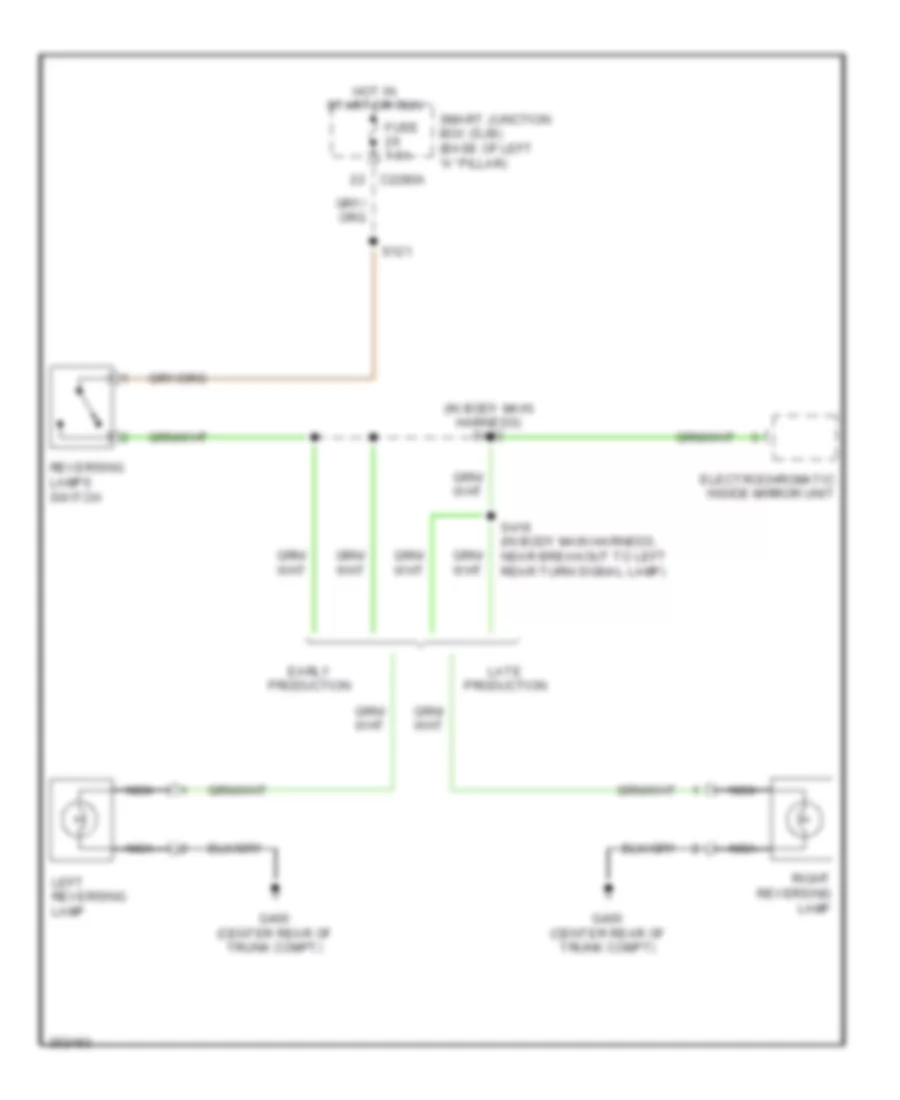
Back-up Lamps Wiring Diagram, M/T for Ford Fusion S 2007
 https://portal-diagnostov.com/license.html
Automotive Electricians Portal FZCO
Automotive Electricians Portal FZCO
https://portal-diagnostov.com/license.html
https://portal-diagnostov.com/license.html
Automotive Electricians Portal FZCO
Automotive Electricians Portal FZCOList of elements for Back-up Lamps Wiring Diagram, M/T for Ford Fusion S 2007:
- (in body main harness) s412
- C2280a
- Early production
- Electrochromatic inside mirror unit
- Fuse 7.5a
- G400 (center rear of trunk compt)
- Hot in start or run
- Late production
- Left reversing lamp
- Nca
- Reversing lamps switch
- Right reversing lamp
- S121
- S416 (in body main harness, near breakout to left rear turn signal lamp)
- Smart junction box (sjb) (base of left "a" pillar)
Exterior Lamps Wiring Diagram (1 of 2) for Ford Fusion S 2007
 https://portal-diagnostov.com/license.html
Automotive Electricians Portal FZCO
Automotive Electricians Portal FZCO
https://portal-diagnostov.com/license.html
https://portal-diagnostov.com/license.html
Automotive Electricians Portal FZCO
Automotive Electricians Portal FZCOList of elements for Exterior Lamps Wiring Diagram (1 of 2) for Ford Fusion S 2007:
- (near breakout to turn lamp left rear) s410
- Auto
- Auto- lamp on
- Battery junction box (3.0l: left front of engine compt) (except 3.0l: left side of engine compt)
- Boo input
- Boo redundant
- C2280a
- C2280d
- C2280f
- Chmsl
- Computer data lines system
- Early production
- Fuse 15a
- Fuse 40a
- Fuse 60a
- G103 (left front of engine compt)
- G104 (3.0l: right front of engine compt) (2.3l: in front of right strut tower)
- G202 (left side of dash)
- G203 (base of right ``a" pillar)
- Hazard on
- Head park- lamp off
- Hot at all times
- Instrument cluster
- Late production
- Left
- Left front park/ turn lamp
- Left front side lamp
- Left turn sig
- Lh stop/ turn lamp
- Logic
- Logic gnd
- Low
- Low beam req
- Lt turn
- Main light switch
- Ms can+
- Ms can-
- Multi- function switch (left side of dash)
- Off
- Park
- Park lamp relay
- Park lamps on
- Rh stop/ turn lamp
- Right
- Right front park/ turn lamp
- Right front side lamp
- Right turn sig
- Rt turn
- S136 (near breakout to front impact severity sensor)
- Smart junction box (sjb) (base of left ``a" pillar)
- Traction ctl led out
- Traction ctl on/off
- Turn
- W/ spoiler
- W/o spoiler
Exterior Lamps Wiring Diagram (2 of 2) for Ford Fusion S 2007
 https://portal-diagnostov.com/license.html
Automotive Electricians Portal FZCO
Automotive Electricians Portal FZCO
https://portal-diagnostov.com/license.html
https://portal-diagnostov.com/license.html
Automotive Electricians Portal FZCO
Automotive Electricians Portal FZCOList of elements for Exterior Lamps Wiring Diagram (2 of 2) for Ford Fusion S 2007:
- (in body main harness, near breakout to g400) s411
- Abs control module (right front of engine compt)
- Battery junction box (3.0l: left front of engine compt) (except 3.0l: left side of engine compt)
- Boo
- Bps
- Brake pedal position switch (left side of dash)
- C175b
- C2280a
- C2280b
- Ccb08
- Ces09
- Early production
- Fuse 15a
- Fuse 7.5a
- G203 (base of right ``a'' pillar)
- G400 (center rear of trunk compt)
- Hazard switch
- Hazard/ pad/ traction switch
- High mounted stoplamp
- Hot at all times
- Hot in start or run
- Interior lights system
- Late production
- Left license plate lamp
- Left rear park/ turn/ stop/lamp
- Left rear side lamp
- Pad
- Park
- Powertrain control module (left rear of engine compt)
- Right license plate lamp
- Right rear park/turn/ stop/lamp
- Right rear side lamp
- S120 (in dash panel to headlamp junction harness, near engine bulkhead grommet)
- S133 (3.0l: in dash panel to headlamp junction harness, near breakout to g103) (except 3.0l: in dash panel to headlamp junction harness, near breakout to side lamp left front)
- S144
- S409
- Smart junction box (sjb) (base of left ``a" pillar)
- Stop lp sw
- Stop/ turn
- Traction
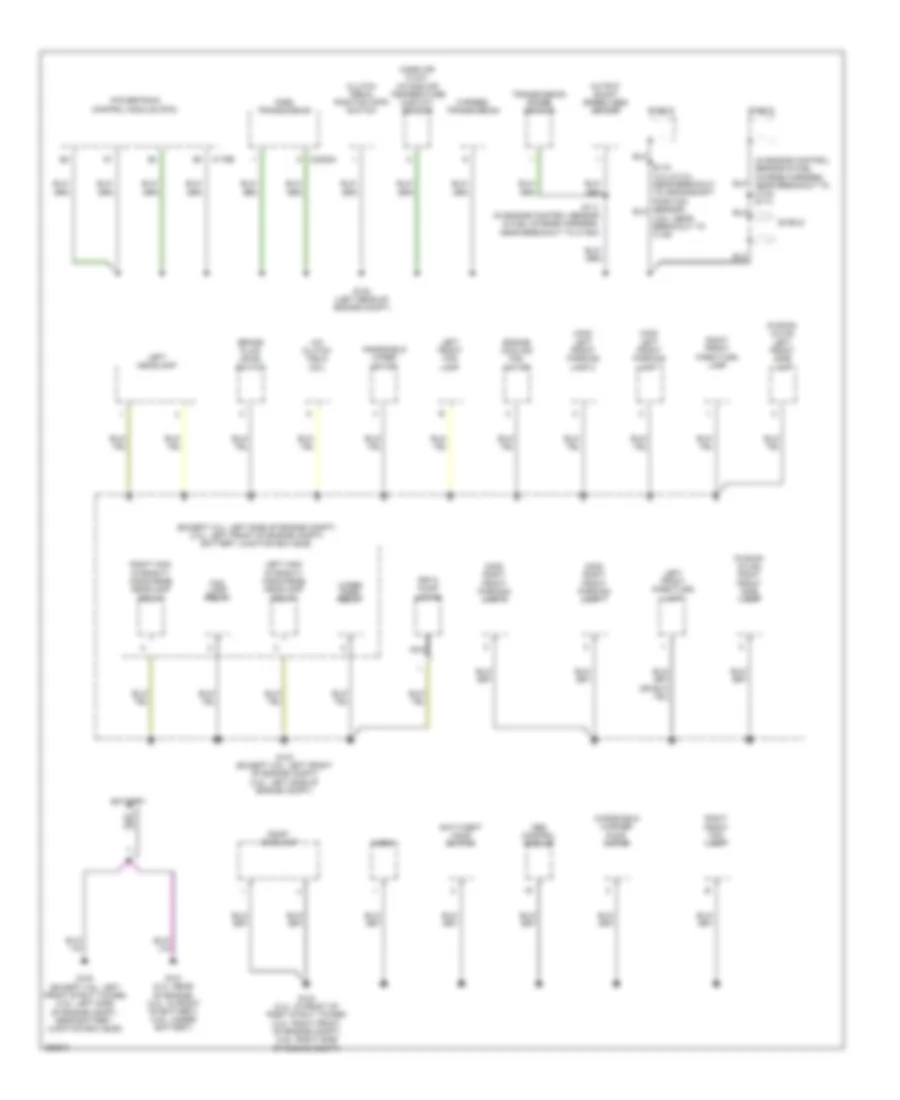
GROUND DISTRIBUTION
Ground Distribution Wiring Diagram (1 of 4) for Ford Fusion S 2007
 https://portal-diagnostov.com/license.html
Automotive Electricians Portal FZCO
Automotive Electricians Portal FZCO
https://portal-diagnostov.com/license.html
https://portal-diagnostov.com/license.html
Automotive Electricians Portal FZCO
Automotive Electricians Portal FZCOList of elements for Ground Distribution Wiring Diagram (1 of 4) for Ford Fusion S 2007:
- (3.5l: near breakout to c145)
- (except 3.0l: left side of engine compt) (3.0l: left front of engine compt) battery junction box (bjb)
- (fusion/ milan) left front side lamp
- (fusion/ milan) right front side lamp
- (in engine control sensor & fuel charge harness, near breakout to c134) s114
- (mkz) left front parking lamp 1
- (mkz) left front parking lamp 2
- (mkz) right front parking lamp 1
- (mkz) right front parking lamp 2
- 6 speed transmission
- A/c clutch field coil
- Abs control module
- Anti-theft hood switch
- Battery
- Brake fluid level switch
- C175b
- C2352a
- Clutch pedal position (cpp) switch
- Control module (pcm)
- Engine cooling fan motor
- Fnr5 transmission
- Fog lamp relay
- G100 (except 3.5l: left front strut tower) (3.5l: left side of engine compt, near battery junction box (bjb))
- G101 (2.3l: rear of engine) (3.0l: in front of battery) (3.5l: under battery)
- G102 (left rear of engine compt)
- G103 (except 3.5l: left front of engine compt) (3.5l: left side of engine compt)
- G104 (2.3l: in front of right strut tower) (3.0l: right front of engine compt) (3.5l: right side of engine compt)
- Horn
- Left front fog lamp
- Left front park/turn lamp
- Left headlamp
- Left high intensity discharge headlamp relay
- Mass air flow/ intake air temperature (maf/iat) sensor
- Nca
- Output shaft speed (oss) sensor
- Peta pump motor
- Powertrain
- Right front fog lamp
- Right front park/turn lamp
- Right headlamp
- Right high intensity discharge headlamp relay
- S111 (in engine control sensor & fuel charge harness, near breakout to c1464)
- Shield
- Transmission range sensor
- Windshield washer pump motor
- Windshield wiper motor
- Wiper park relay
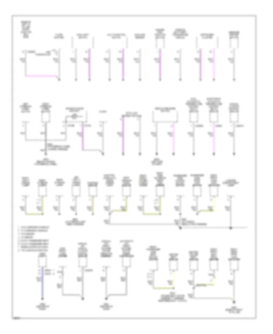
Ground Distribution Wiring Diagram (2 of 4) for Ford Fusion S 2007
 https://portal-diagnostov.com/license.html
Automotive Electricians Portal FZCO
Automotive Electricians Portal FZCO
https://portal-diagnostov.com/license.html
https://portal-diagnostov.com/license.html
Automotive Electricians Portal FZCO
Automotive Electricians Portal FZCOList of elements for Ground Distribution Wiring Diagram (2 of 4) for Ford Fusion S 2007:
- (automatic a/c) front blower motor speed controller
- (base of left "a" pillar) smart junction box (sjb)
- (manual a/c) front blower motor resistor assembly
- (manual a/c) manual climate control module
- (mkz) front cigar lighter
- 6-way passenger seat
- 8-way passenger seat
- Air bag sliding contact
- Audio unit
- Base/audiophile audio
- C218a
- C218b
- C2280d
- C228a
- C2356a
- C2357a
- C2357b
- C240a
- C290a
- Clock
- Compass module
- Data link connector (dlc)
- Decklid release switch
- Dual automatic temperature control (datc) module
- Electro- chromatic inside mirror unit
- Electronic automatic temperature control (eatc) module
- Floor shifter
- Front interior lamp
- Front passenger side seat adjust switch
- G200 (center of dash)
- G201 (center of dash)
- G202 (left side of dash)
- G203 (base of right "a" pillar)
- G204 (behind air bag, in steering wheel)
- Hazard/ pad/ traction switch
- Heated seat module
- Heated/ cooled seat module
- Instrument cluster
- Left steering wheel switch
- Left vanity mirror lamp
- Luggage compartment lamp
- Main light switch
- Manual climate control module
- Message center switch
- Mkz fusion/milan
- Multi-function switch
- Nca
- Passenger side door lock switch
- Passenger side window adjust switch
- Passive anti-theft transceiver module
- Rear interior lamp
- Right front door lock actuator
- Right front power window motor
- Right front seat back heater
- Right rear door lock actuator
- Right side exterior rear view mirror
- Right steering wheel switch
- Right vanity mirror lamp
- Roof opening panel module
- S303 (power seat motor assembly harness, near breakout to c313)
- S601 (in window regulator harness)
- S902 (in interior lamp feed harness)
- Sunload sensor
- Thx audio/navagation
- W/ memory
- W/ overhead console
- W/o memory
- W/o overhead console
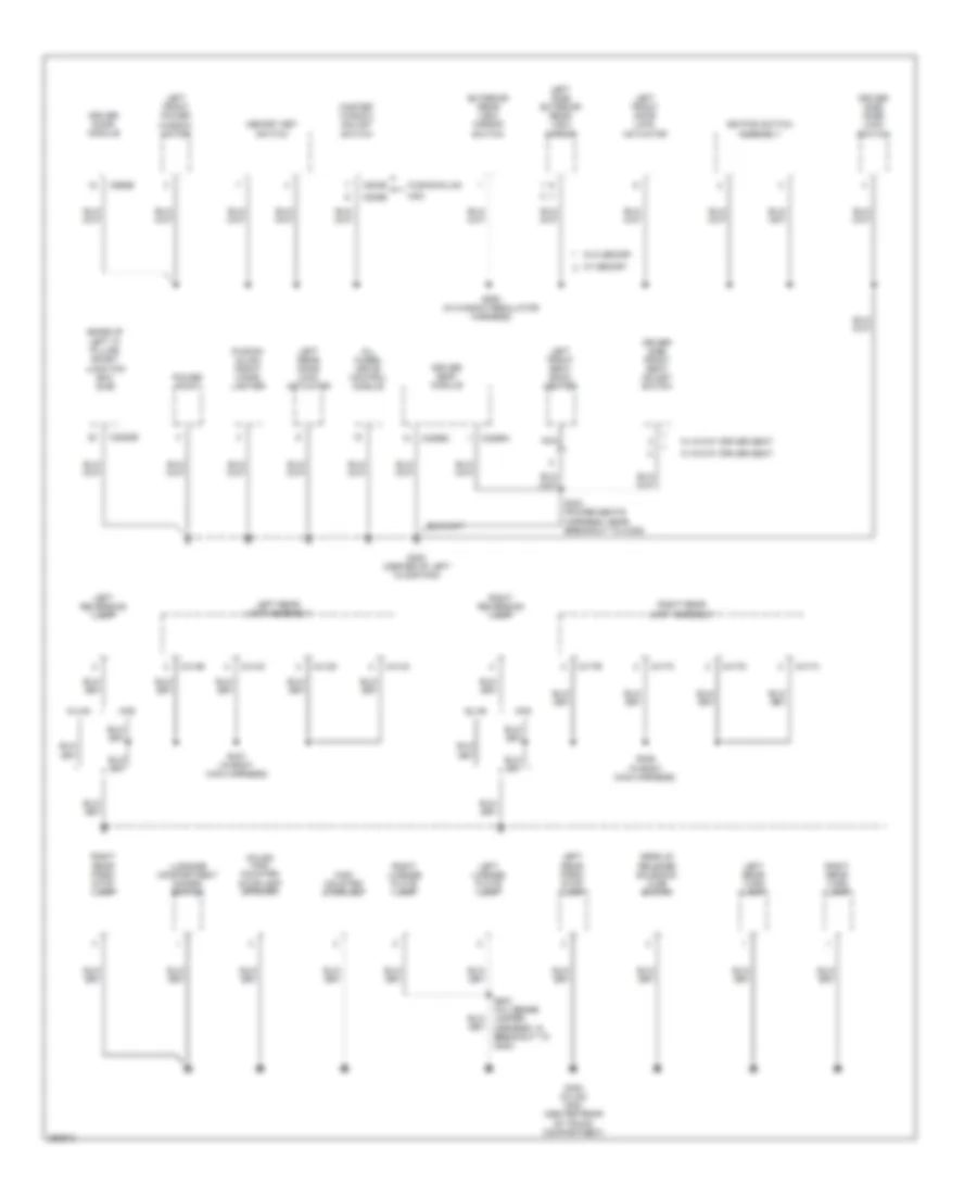
Ground Distribution Wiring Diagram (3 of 4) for Ford Fusion S 2007
 https://portal-diagnostov.com/license.html
Automotive Electricians Portal FZCO
Automotive Electricians Portal FZCO
https://portal-diagnostov.com/license.html
https://portal-diagnostov.com/license.html
Automotive Electricians Portal FZCO
Automotive Electricians Portal FZCOList of elements for Ground Distribution Wiring Diagram (3 of 4) for Ford Fusion S 2007:
- (base of left "a" pillar) smart junction box (sjb)
- (fusion/ milan) front cigar lighter
- (in body main harness)
- (milan) high mounted stoplamp (spoiler)
- All wheel drive control module
- C2280e
- C3299a
- C3299c
- C414a
- C414b
- C414c
- C414d
- C417a
- C417b
- C417c
- C417d
- C504b
- C535b
- C568b
- Decklid release solenoid/ ajar switch
- Driver door module
- Driver seat module
- Driver side door lock switch
- Driver side front seat adjust switch
- Exterior rear view mirror switch
- Fusion/milan
- G300 (center of left floor pan)
- G400 (milan/ mkz) (center rear of trunk compartment)
- High mounted stoplamp
- Keypad switch assembly
- Left front door lock actuator
- Left front power window motor
- Left front seat back heater
- Left license plate lamp
- Left rear door lock actuator
- Left rear lamp assembly
- Left rear park/ stop lamp
- Left rear turn lamp
- Left reversing lamp
- Left side exterior rear view mirror
- Luggage compartment disarm switch
- Master window adjust switch
- Memory set switch
- Milan
- Mkz
- Nca
- Power point
- Right license plate lamp
- Right rear lamp assembly
- Right rear park/ stop lamp
- Right rear turn lamp
- Right reversing lamp
- S304 (power seats harness, near breakout to c339)
- S336
- S337 (in body main harness)
- S400 (in license jumper harness, in breakout to c405)
- S500 (in window regulator harness)
- W/ 6-way driver seat
- W/ 8-way driver seat
- W/ memory
- W/o memory
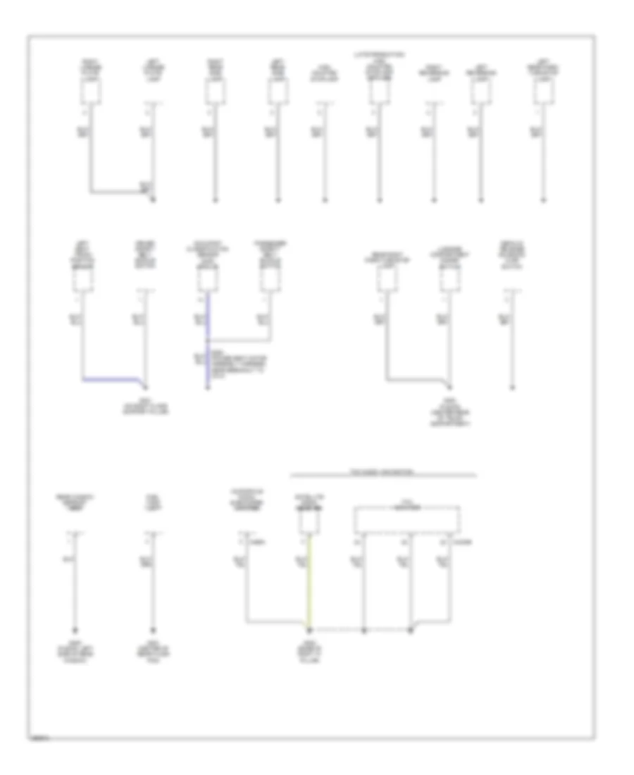
Ground Distribution Wiring Diagram (4 of 4) for Ford Fusion S 2007
 https://portal-diagnostov.com/license.html
Automotive Electricians Portal FZCO
Automotive Electricians Portal FZCO
https://portal-diagnostov.com/license.html
https://portal-diagnostov.com/license.html
Automotive Electricians Portal FZCO
Automotive Electricians Portal FZCOList of elements for Ground Distribution Wiring Diagram (4 of 4) for Ford Fusion S 2007:
- (audiophile audio) subwoofer amplifier
- (late production) high mounted stoplamp (spoiler)
- C4330b
- C466a
- Decklid release solenoid/ ajar switch
- Driver safety belt buckle switch
- Fuel tank unit
- G301 (on right floor support pillar)
- G400 (fusion) (center rear of trunk compartment)
- G401 (center of rear floor pan)
- G402 (base of right "c" pillar)
- G405 (fusion: left side of rear window)
- High mounted stoplamp
- Left license plate lamp
- Left rear park/ turn/stop lamp
- Left rear side lamp
- Left reversing lamp
- Left seat track position sensor
- Luggage compartment disarm switch
- Occupant classification sensor (ocs) module
- Passenger safety belt buckle switch
- Rear right park/turn/stop lamp
- Rear window defrost grid
- Right license plate lamp
- Right rear side lamp
- Right reversing lamp
- S300 (power seat motor assembly harness, near breakout to c313)
- Satellite radio receiver
- Thx amplifier
- Thx audio / navigation
HEADLIGHTS
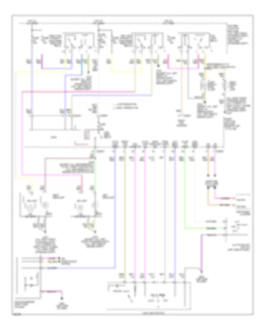
Headlights Wiring Diagram, with Autolamps with High Intensity Gas Discharge Headlights for Ford Fusion S 2007
 https://portal-diagnostov.com/license.html
Automotive Electricians Portal FZCO
Automotive Electricians Portal FZCO
https://portal-diagnostov.com/license.html
https://portal-diagnostov.com/license.html
Automotive Electricians Portal FZCO
Automotive Electricians Portal FZCOList of elements for Headlights Wiring Diagram, with Autolamps with High Intensity Gas Discharge Headlights for Ford Fusion S 2007:
- (3.0l: right front of engine compt) (2.3l: in front of right strut tower) (3.5l: right side of engine compt) g104
- Air conditioning system
- Auto
- Auto- lamp on
- Auto- lamp sens
- Ballast
- Battery junction box (bjb) (3.0l: left front of engine compt) (except 3.0l: left side of engine compt)
- C2280a
- C2280d
- C2280f
- Computer data lines system
- Early production
- Flash to pass
- Fog
- Fog ind
- Fog lamp relay
- Fog lamps on
- Front fog command
- Front fog ind
- Ftp
- Fuse 15a
- Fuse 40a
- Fuse 60a fuse 60a
- G103 (except 3.5l: left front of engine compt) (3.5l: left side of engine compt)
- G104 (3.0l: right front of engine compt) (2.3l: in front of right strut tower) (3.5l: right side of engine compt)
- G202 (left side of dash)
- Head parklamp off
- Hi beam
- Hid low beam
- High beam relay
- High beam req
- Hot at all times
- Instrument cluster
- Late production
- Left front fog lamp
- Left headlamp
- Left high intensity discharge headlamp relay
- Logic
- Low
- Low beam req
- Main light switch
- Ms can+
- Ms can-
- Multifunction switch (left side of dash)
- Off
- Park
- Park lamps on
- Right front fog lamp
- Right headlamp
- Right high intensity discharge headlamp relay
- S135 (except 3.5l: near breakout to anti-theft hood switch) (3.5l: near breakout to engine cooling fan motor)
- Smart junction box (sjb) (base of left ``a" pillar)
- Sunload sensor (right side of dash)
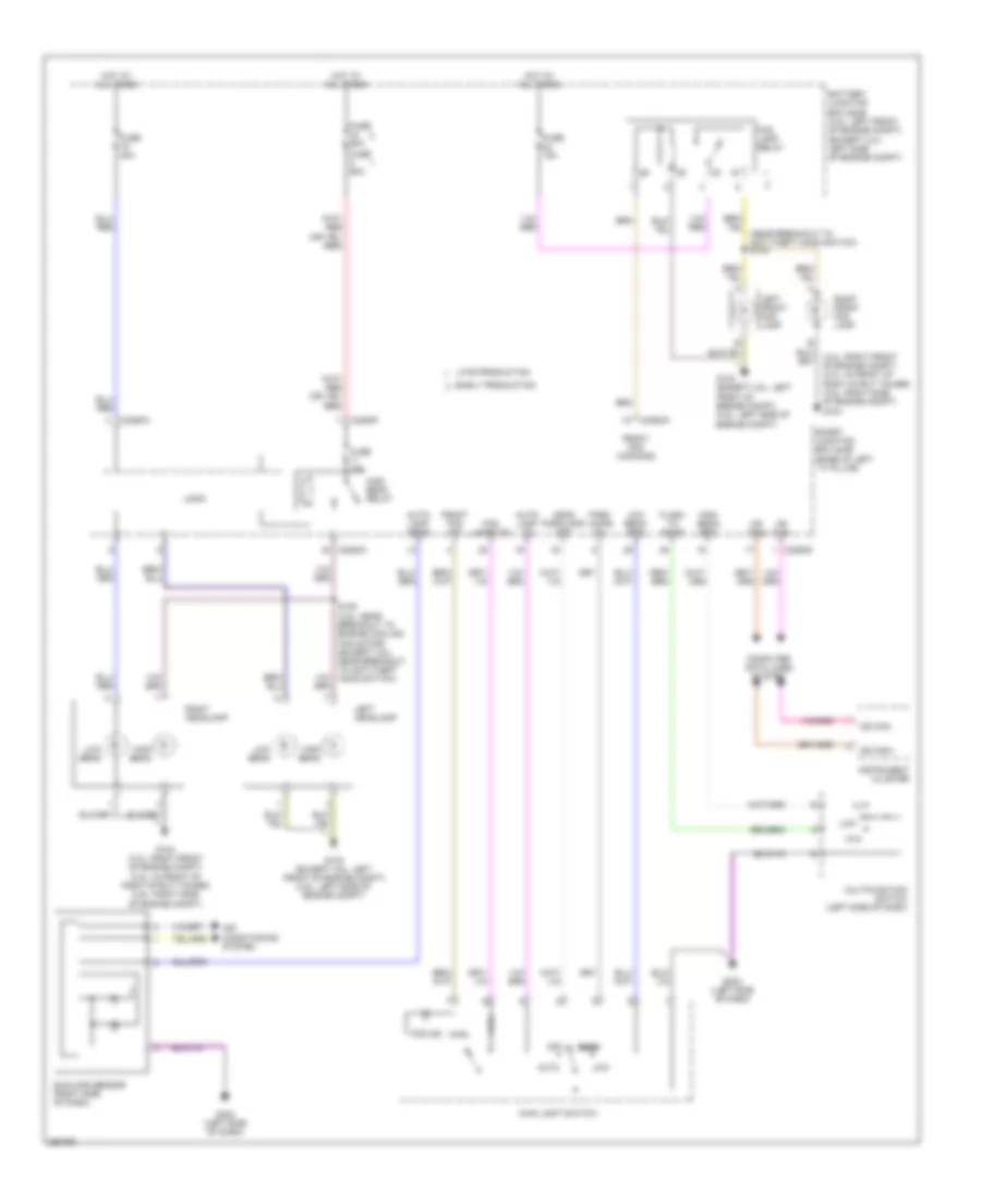
Headlights Wiring Diagram, with Autolamps without High Intensity Gas Discharge Headlights for Ford Fusion S 2007
 https://portal-diagnostov.com/license.html
Automotive Electricians Portal FZCO
Automotive Electricians Portal FZCO
https://portal-diagnostov.com/license.html
https://portal-diagnostov.com/license.html
Automotive Electricians Portal FZCO
Automotive Electricians Portal FZCOList of elements for Headlights Wiring Diagram, with Autolamps without High Intensity Gas Discharge Headlights for Ford Fusion S 2007:
- (3.0l: right front of engine compt) (2.3l: in front of right strut tower) (3.5l: right side of engine compt) g104
- Air conditioning system
- Auto
- Auto- lamp on
- Auto- lamp sens
- Battery junction box (bjb) (3.0l: left front of engine compt) (except 3.0l: left side of engine compt)
- C2280a
- C2280d
- C2280f
- Computer data lines system
- Early production
- Flash to pass
- Fog
- Fog ind
- Fog lamp relay
- Fog lamps on
- Front fog command
- Front fog ind
- Ftp
- Fuse 15a
- Fuse 40a
- Fuse 60a
- G103 (except 3.5l: left front of engine compt) (3.5l: left side of engine compt)
- G104 (3.0l: right front of engine compt) (2.3l: in front of right strut tower) (3.5l: right side of engine compt)
- G202 (left side of dash)
- Head parklamp off
- High beam
- High beam relay
- High beam req
- Hot at all times
- Instrument cluster
- Late production
- Left front fog lamp
- Left headlamp
- Logic
- Low
- Low beam
- Low beam req
- Main light switch
- Ms can+
- Ms can-
- Multifunction switch (left side of dash)
- Off
- Park
- Park lamps on
- Right front fog lamp
- Right headlamp
- S135 (3.5l: near breakout to engine cooling fan motor) (except 3.5l: near breakout to anti-theft hood switch)
- Smart junction box (sjb) (base of left ``a" pillar)
- Sunload sensor (right side of dash)
Headlights Wiring Diagram, without Autolamps with High Intensity Gas Discharge Headlights for Ford Fusion S 2007
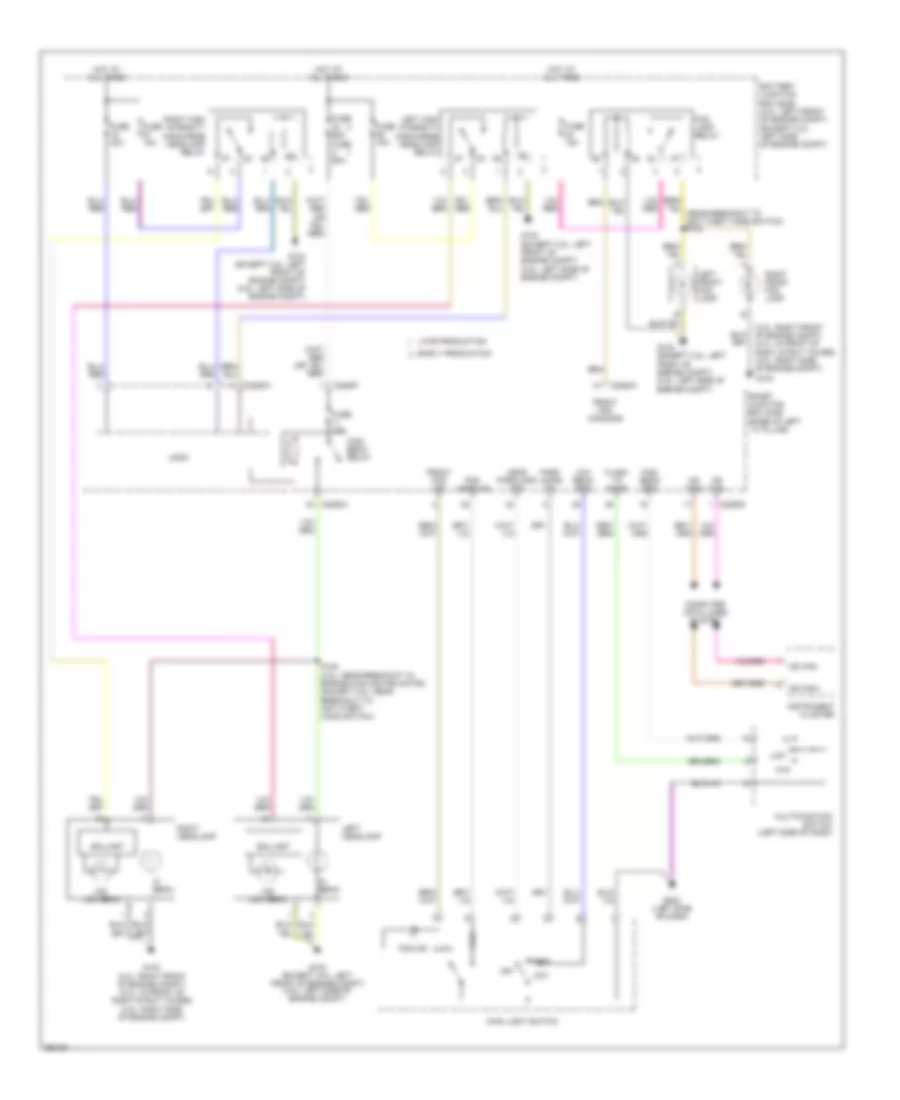 https://portal-diagnostov.com/license.html
Automotive Electricians Portal FZCO
Automotive Electricians Portal FZCO
https://portal-diagnostov.com/license.html
https://portal-diagnostov.com/license.html
Automotive Electricians Portal FZCO
Automotive Electricians Portal FZCOList of elements for Headlights Wiring Diagram, without Autolamps with High Intensity Gas Discharge Headlights for Ford Fusion S 2007:
- (3.0l: right front of engine compt) (2.3l: in front of right strut tower) (3.5l: right side of engine compt)
- Ballast
- Battery junction box (bjb) (3.0l: left front of engine compt) (except 3.0l: left side of engine compt)
- C2280a
- C2280d
- C2280f
- Computer data lines system
- Early production
- Flash to pass
- Fog
- Fog ind
- Fog lamp relay
- Fog lamps on
- Front fog command
- Front fog ind
- Ftp
- Fuse 15a
- Fuse 40a
- Fuse 60a
- G103 (except 3.5l: left front of engine compt) (3.5l: left side of engine compt)
- G104
- G104 (3.0l: right front of engine compt) (2.3l: in front of right strut tower) (3.5l: right side of engine compt)
- G202 (left side of dash)
- Head parklamp off
- Hi beam
- Hid low beam
- High beam relay
- High beam req
- Hot at all times
- Instrument cluster
- Late production
- Left front fog lamp
- Left headlamp
- Left high intensity discharge headlamp relay
- Logic
- Low
- Low beam req
- Main light switch
- Ms can+
- Ms can-
- Multifunction switch (left side of dash)
- Off
- Park
- Park lamps on
- Right front fog lamp
- Right headlamp
- Right high intensity discharge headlamp relay
- S135 (3.5l: near breakout to engine cooling fan motor) (except 3.5l: near breakout to anti-theft hood switch)
- Smart junction box (sjb) (base of left ``a" pillar)
Headlights Wiring Diagram, without Autolamps without High Intensity Gas Discharge Headlights for Ford Fusion S 2007
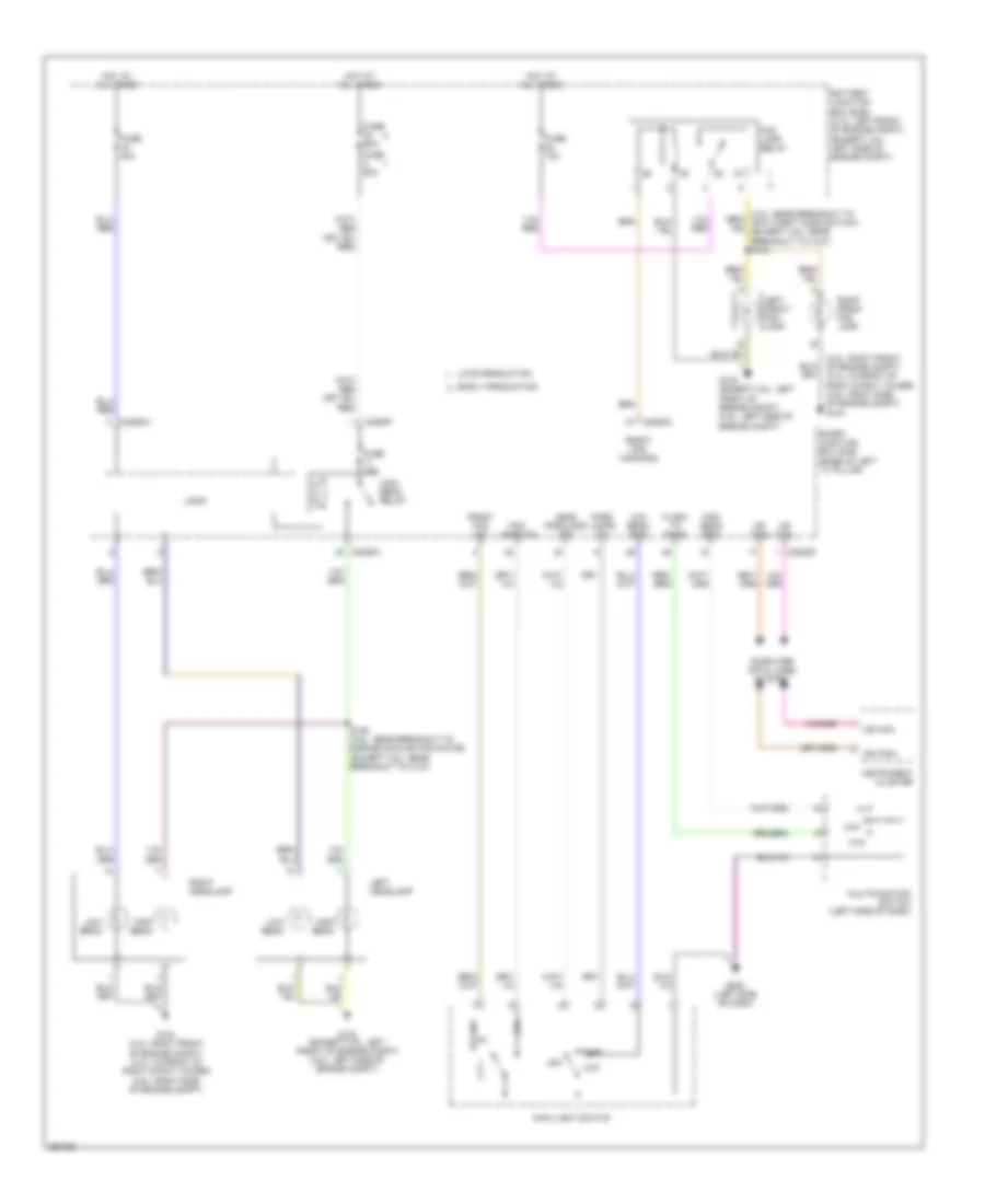 https://portal-diagnostov.com/license.html
Automotive Electricians Portal FZCO
Automotive Electricians Portal FZCO
https://portal-diagnostov.com/license.html
https://portal-diagnostov.com/license.html
Automotive Electricians Portal FZCO
Automotive Electricians Portal FZCOList of elements for Headlights Wiring Diagram, without Autolamps without High Intensity Gas Discharge Headlights for Ford Fusion S 2007:
- (3.0l: right front of engine compt) (2.3l: in front of right strut tower) (3.5l: right side of engine compt) g104
- Battery junction box (bjb) (3.0l: left front of engine compt) (except 3.0l: left side of engine compt)
- C2280a
- C2280d
- C2280f
- Computer data lines system
- Early production
- Flash to pass
- Fog
- Fog ind
- Fog lamp relay
- Fog lamps on
- Front fog command
- Front fog ind
- Ftp
- Fuse 15a
- Fuse 40a
- Fuse 60a
- G103 (except 3.5l: left front of engine compt) (3.5l: left side of engine compt)
- G104 (3.0l: right front of engine compt) (2.3l: in front of right strut tower) (3.5l: right side of engine compt)
- G202 (left side of dash)
- Head parklamp off
- High beam
- High beam relay
- High beam req
- Hot at all times
- Instrument cluster
- Late production
- Left front fog lamp
- Left headlamp
- Logic
- Low
- Low beam
- Low beam req
- Main light switch
- Ms can+
- Ms can-
- Multifunction switch (left side of dash)
- Off
- Park
- Park lamps on
- Right front fog lamp
- Right headlamp
- S135 (3.5l: near breakout to engine cooling fan motor) (except 3.5l: near breakout to c127)
- Smart junction box (sjb) (base of left ``a" pillar)
HORN
Horn Wiring Diagram for Ford Fusion S 2007
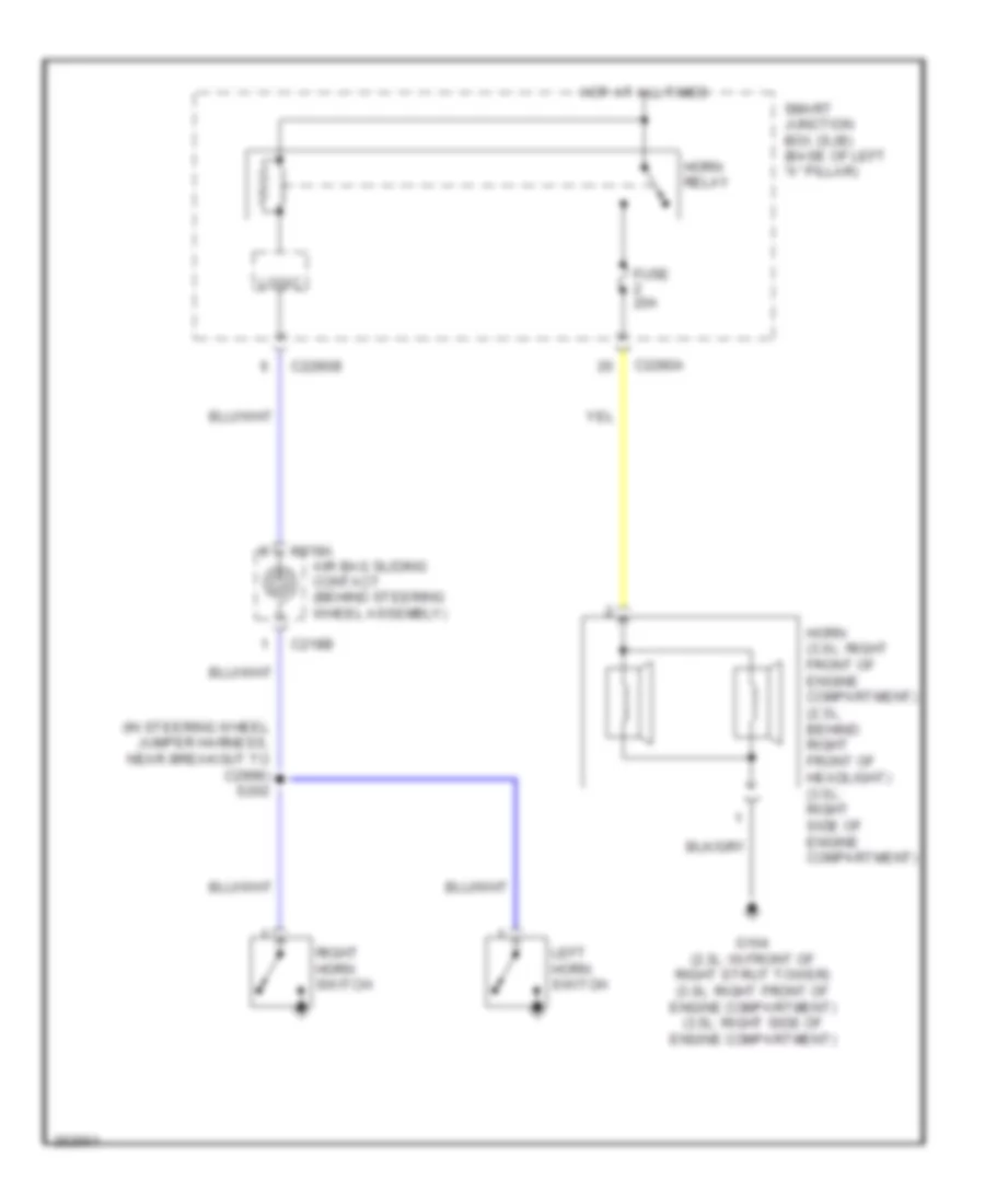 https://portal-diagnostov.com/license.html
Automotive Electricians Portal FZCO
Automotive Electricians Portal FZCO
https://portal-diagnostov.com/license.html
https://portal-diagnostov.com/license.html
Automotive Electricians Portal FZCO
Automotive Electricians Portal FZCOList of elements for Horn Wiring Diagram for Ford Fusion S 2007:
- (in steering wheel jumper harness, near breakout to c2998) s202
- Air bag sliding contact (behind steering wheel assembly)
- C218a
- C218b
- C2280a
- C2280b
- Fuse 20a
- G104 (2.3l: in front of right strut tower) (3.0l: right front of engine compartment) (3.5l: right side of engine compartment)
- Horn (3.0l: right front of engine compartment) (2.3l: behind right front of headlight) (3.5l: right side of engine compartment)
- Horn relay
- Hot at all times
- Left horn switch
- Logic
- Right horn switch
- Smart junction box (sjb) (base of left "a" pillar)
INSTRUMENT CLUSTER
Instrument Cluster Wiring Diagram for Ford Fusion S 2007
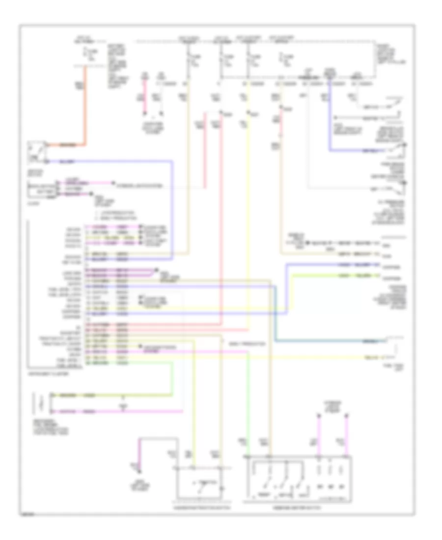 https://portal-diagnostov.com/license.html
Automotive Electricians Portal FZCO
Automotive Electricians Portal FZCO
https://portal-diagnostov.com/license.html
https://portal-diagnostov.com/license.html
Automotive Electricians Portal FZCO
Automotive Electricians Portal FZCOList of elements for Instrument Cluster Wiring Diagram for Ford Fusion S 2007:
- (base of right "a" pillar)
- A/c req
- Air conditioning system
- Anti-theft system
- Awd
- Backlighting
- Battery
- Battery junction box (bjb) (2.3l: left side of engine compt) (3.0l: left front of engine compt)
- Brake fluid level switch (left rear of engine compt)
- C228oa
- C228ob
- C228oc
- C228od
- C228oe
- Cbp19
- Cbp20
- Cbp23
- Cca10
- Cca15
- Cdc30
- Ch434
- Clock
- Cmc29
- Compass module (w/ moonroof: in roof harness) (front center of roof)
- Compass+
- Compass-
- Computer data lines system
- Early production
- Fuel level 1
- Fuel level 1 rtn
- Fuel level 2
- Fuel level 2 rtn
- Fuel tank unit
- Fuse 10a
- Fuse 15a
- Fuse 7.5a
- G103 (left front of engine compt)
- G202 (left side of dash)
- G203
- Gd116
- Gd139
- Gnd
- Hazard/pad/traction switch
- Hot at all times
- Hot in run or acc
- Hot in start or run
- Hs can+
- Hs can-
- Ignition switch
- Info
- Instrument cluster
- Interior lights system
- Key in
- Key in ign
- Late production
- Logic gnd
- Low brk fl
- Low oil pressure
- Message center switch
- Ms can+
- Ms can-
- Ms rtn
- Ms sw
- Oil pressure switch (2.3l: on oil filter housing) (3.0l: left side of engine block)
- Park brake sw
- Park brake switch (under center console)
- Pats rx
- Pats tx
- Pwr
- Pwr gnd
- Reset
- Rmc27
- Rmc32
- Rmc33
- Run/acc
- Run/start
- S227
- S229
- S329
- S902
- Sbp07
- Secondary fuel sender (late production) (top of fuel tank)
- Setup
- Smart junction box (sjb) (base of left "a" pillar)
- Traction
- Traction ctl led out
- Traction ctl on/off
- Vdb04
- Vdb05
- Vdb06
- Vdb07
- Vmc11
- Vmc23
- Vmc30
- Vmc31
- Vrt23
- Vrt24
INTERIOR LIGHTS
Courtesy Lamps Wiring Diagram, Early Production for Ford Fusion S 2007
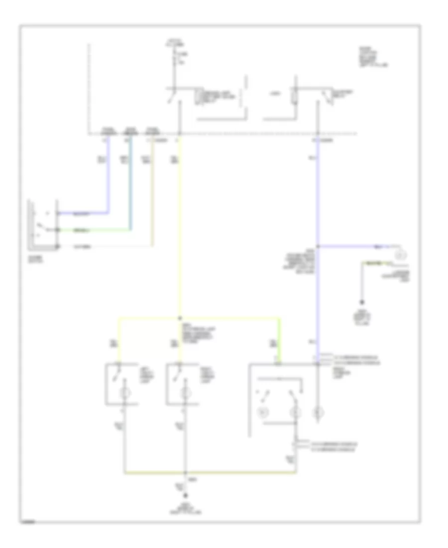 https://portal-diagnostov.com/license.html
Automotive Electricians Portal FZCO
Automotive Electricians Portal FZCO
https://portal-diagnostov.com/license.html
https://portal-diagnostov.com/license.html
Automotive Electricians Portal FZCO
Automotive Electricians Portal FZCOList of elements for Courtesy Lamps Wiring Diagram, Early Production for Ford Fusion S 2007:
- C2280d
- C2280e
- Courtesy relay
- Demand lamp/ battery saver relay
- Dimmer switch
- Dome demand
- Front interior lamp
- Fuse 15a
- G203 (base of right "a" pillar)
- Hot at all times
- Left vanity mirror lamp
- Logic
- Luggage compartment lamp
- Panel dim gnd
- Panel dimming
- Right vanity mirror lamp
- S320 (power seats harness, near breakout to smart junction box (sjb))
- S902
- S903 (in interior lamp feed harness, near breakout to c906)
- Smart junction box (sjb) (base of left "a" pillar)
- W/ overhead console
- W/o overhead console
Courtesy Lamps Wiring Diagram, Late Production for Ford Fusion S 2007
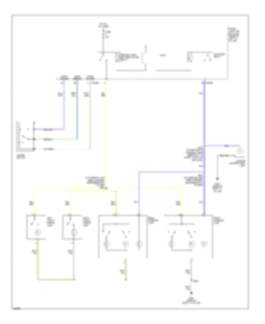 https://portal-diagnostov.com/license.html
Automotive Electricians Portal FZCO
Automotive Electricians Portal FZCO
https://portal-diagnostov.com/license.html
https://portal-diagnostov.com/license.html
Automotive Electricians Portal FZCO
Automotive Electricians Portal FZCOList of elements for Courtesy Lamps Wiring Diagram, Late Production for Ford Fusion S 2007:
- (in interior lamp feed harness, near breakout to c906) s903
- C2280d
- C2280e
- Courtesy relay
- Demand lamp/ battery saver relay
- Dimmer switch
- Dome demand
- Front interior lamp
- Fuse 15a
- G203 (base of right "a" pillar)
- Hot at all times
- Left vanity mirror lamp
- Logic
- Luggage compartment lamp
- Panel dim gnd
- Panel dimming
- Rear interior lamp
- Right vanity mirror lamp
- S320 (power seats harness, near breakout to smart junction box (sjb))
- S901 (in interior lamp feed harness, near breakout to c906)
- S902
- Smart junction box (sjb) (base of left "a" pillar)
Instrument Illumination Wiring Diagram for Ford Fusion S 2007
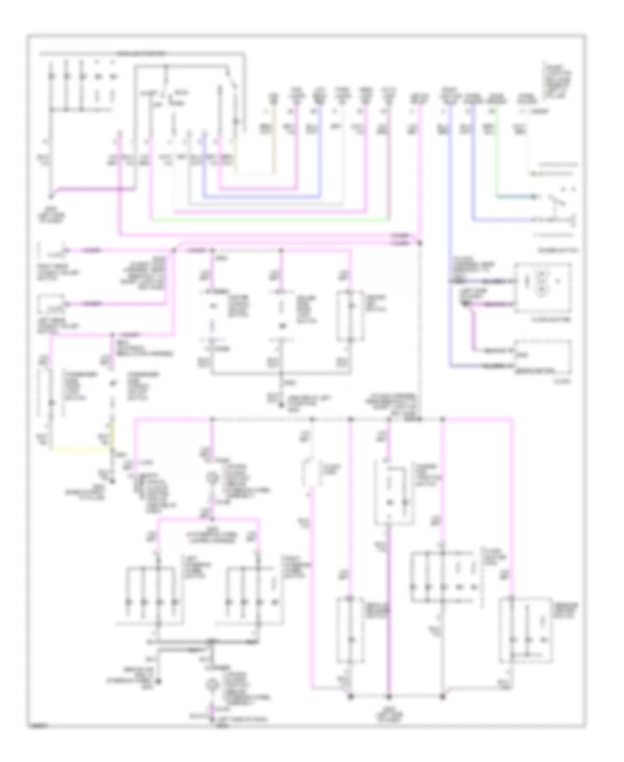 https://portal-diagnostov.com/license.html
Automotive Electricians Portal FZCO
Automotive Electricians Portal FZCO
https://portal-diagnostov.com/license.html
https://portal-diagnostov.com/license.html
Automotive Electricians Portal FZCO
Automotive Electricians Portal FZCOList of elements for Instrument Illumination Wiring Diagram for Ford Fusion S 2007:
- (behind air bag, in steering wheel) g204
- (center of left floor pan) g300
- (in main harness, near breakout to g201) s233
- (in main harness, near breakout to smart junction box (sjb)) s230
- (left side of dash) g202
- Air bag sliding contact (behind steering wheel assembly)
- Auto
- Auto- lamp on
- Back- lighting
- Back- lighting bulb
- Backlighting
- C218a
- C218b
- C2280d
- C2357a
- C535a
- C535b
- Clock
- Clock (mkz)
- Decklid release switch
- Dimmer switch
- Dome demand
- Driver side door lock switch
- Floor shifter
- Floor shifter (mkz)
- Fog ind
- Fog- lamps on
- G202 (left side of dash)
- G203 (base of right "a" pillar)
- Gnd
- Hazard/ pad traction switch
- Head lamp off
- Illum
- Led sw bklgt
- Left rear window adjust switch
- Left steering wheel switch
- Low
- Low beam req
- Main light switch
- Manual climate control module (center of dash)
- Master window adjust switch
- Memory set switch
- Message center switch
- Off
- Panel dim gnd
- Panel dimming
- Park
- Park lamps on
- Passenger side door lock switch
- Passenger side window adjust switch
- Right rear window adjust switch
- Right steering wheel switch
- S200 (in steering wheel jumper harness)
- S203
- S339 (in body main harness, near breakout to smart junction box (sjb))
- S500
- S502
- S601
- S605 (in window regulator harness)
- Smart junction box (sjb) (base of left "a" pillar)
POWER DISTRIBUTION
Power Distribution Wiring Diagram (1 of 3) for Ford Fusion S 2007
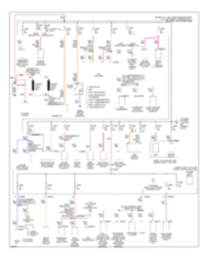 https://portal-diagnostov.com/license.html
Automotive Electricians Portal FZCO
Automotive Electricians Portal FZCO
https://portal-diagnostov.com/license.html
https://portal-diagnostov.com/license.html
Automotive Electricians Portal FZCO
Automotive Electricians Portal FZCOList of elements for Power Distribution Wiring Diagram (1 of 3) for Ford Fusion S 2007:
- (3.0l: near breakout to powertrain control module (pcm)) s127
- (base of left "a" pillar) smart junction box (sjb)
- (except 3.0l: left side of engine compt) (3.0l: left front of engine compt) battery junction box (bjb)
- (except 3.5l) (3.5l)
- (except 3.5l: near breakout to generator) s100
- (in main harness, near breakout to g201) s229
- (in main harness, near breakout to main light switch) s231
- (near breakout to amplifier) s402
- (near breakout to amplifier) s403
- 20a
- 6-way driver seat
- 6-way passenger seat
- 7.5a
- 8-way driver seat w/o memory
- 8-way passenger seat
- Abs control module
- Audio unit
- Base/ audiophile audio
- Battery
- Brake pedal position switch
- C175b
- C2280a
- C2280b
- C2280e
- C2280f
- C228a
- C2352a
- C2356a
- C2357a
- C240a
- C290a
- C3299a
- C3299c
- C3305a
- C4325b
- C466a
- Clock
- Data link connector (dlc)
- Defrost relay
- Driver seat module
- Driver seat module (w/ memory)
- Driver side front seat adjust switch
- Dual automatic temperature control (datc) module (dual zone climate control)
- Early production
- Electronic automatic temperature control (eatc) module (single zone climate control)
- Engine cooling fan motor
- Evap canister vent control solenoid
- Fnr5 transmission
- Fuse
- Fuse 10a
- Fuse 15a
- Fuse 20a
- Fuse 20a 30a
- Fuse 30a
- Fuse 40a
- Fuse 60a
- Fuse 60a 10a
- Fuse 60a 80a
- Fuse 7.5a
- Fusion/milan
- G300 (center of left floor pan)
- Generator
- Heated seat module (if equipped)
- Heated/cooled seat module (if equipped)
- Instrument cluster
- Late production
- Left front power window motor
- Logic
- Manual climate control module (w/ manual a/c)
- Mkz
- Passenger side front seat adjust switch
- Power point
- Powertrain control module (pcm)
- Red
- Right front power window motor
- Roof opening panel module
- S101 (except 3.5l: near breakout to generator)
- S302 (near breakout to occupant classification sensor)
- Smart junction box (sjb) (base of left "a" pillar)
- Starter motor
- Subwoofer amplifier (audiophile audio)
- Thx amplifier
- Thx audio/ navigation
- To c339) s309
- To fuse 10 battery junction box (diagram 2 of 3)
- To fuse 2 battery junction box (diagram 2 of 3)
- To fuse 20 smart junction box (diagram 3 of 3)
- To pcm power relay (diagram 2 of 3)
- Washer pump relay
Power Distribution Wiring Diagram (2 of 3) for Ford Fusion S 2007
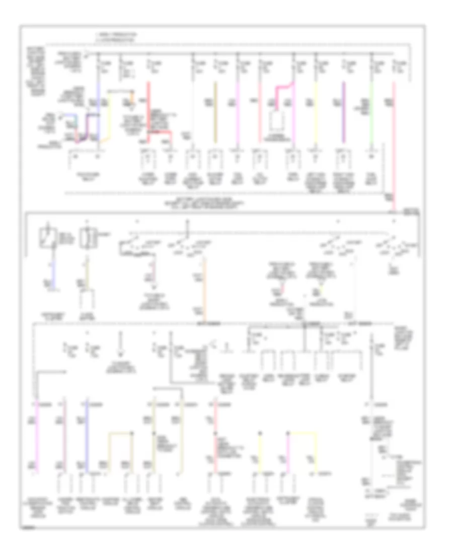 https://portal-diagnostov.com/license.html
Automotive Electricians Portal FZCO
Automotive Electricians Portal FZCO
https://portal-diagnostov.com/license.html
https://portal-diagnostov.com/license.html
Automotive Electricians Portal FZCO
Automotive Electricians Portal FZCOList of elements for Power Distribution Wiring Diagram (2 of 3) for Ford Fusion S 2007:
- (near breakout to battery junction box (bjb))
- (near breakout to battery junction box (bjb)) s128
- (not used)
- 6 speed transmission
- A/c clutch relay
- Abs control module
- Acc
- All wheel drive control module
- Audio unit
- Base/ audiophile audio
- Battery junction box (bjb) (except 3.0l: left side of engine compt) (3.0l: left front of engine compt)
- Blower motor relay
- C175b
- C2280a
- C2280b
- C2280e
- C2280f
- C228a
- C2356a
- C2357a
- C240a
- C290a
- C310a
- Compass module
- Courtesy relay (fusion/ milan)
- Demand lamp/ battery saver relay
- Dual automatic temperature control (datc) module (dual zone climate control)
- Early production
- Electronic automatic temperature control (eatc) module (single zone climate control)
- Floor shifter
- Fnr5 relay
- Fog lamp relay
- From fuse 2 battery junction box (diagram 2 of 3)
- From fuse 23 battery junction box (diagram 1 of 3)
- From fuse 6 battery junction box (diagram 1 of 3)
- From splice s127 (diagram 1 of 3)
- Fuel pump relay
- Fuse 10a
- Fuse 15a
- Fuse 20a
- Fuse 30a
- Fuse 40a
- Fuse 40a 60a
- Fuse 7.5a
- Hazard/ pad/ traction switch
- Heated seat module
- Hi beam relay
- High current peta pump relay
- Horn relay
- Ignition switch
- Inhibit
- Instrument cluster
- Key in ignition switch
- Late production
- Left high intensity discharge headlamp relay
- Lock
- Manual climate control module (w/ manual a/c)
- Occupant classification sensor (ocs) module
- Off
- Park lamp relay
- Pcm power relay
- Powertrain control module (pcm) (except 2.3l)
- Red
- Restraints control module
- Reversing lamps relay
- Right high intensity discharge headlamp relay
- Run
- S143
- S329 (near breakout to g300)
- Smart junction box (sjb) (base of left "a" pillar)
- Start
- Starter relay
- Thx audio/ navigation
- To accessory delay relay smart junction box (diagram 3 of 3)
- To fuse 10 battery junction box (diagram 2 of 3)
- To fuse 23 smart junction box (diagram 3 of 3)
- To smart junction box (diagram 3 of 3)
- Wiper park relay
- Wiper run/park relay
Power Distribution Wiring Diagram (3 of 3) for Ford Fusion S 2007
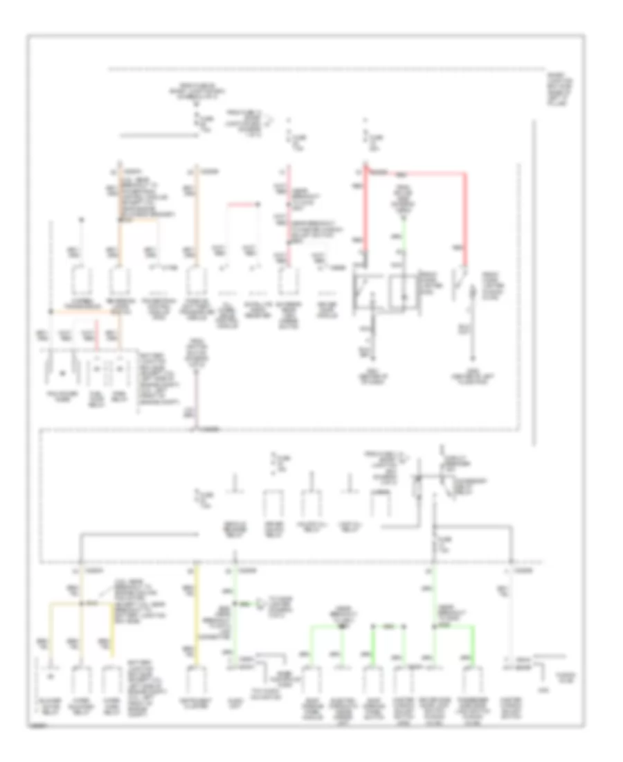 https://portal-diagnostov.com/license.html
Automotive Electricians Portal FZCO
Automotive Electricians Portal FZCO
https://portal-diagnostov.com/license.html
https://portal-diagnostov.com/license.html
Automotive Electricians Portal FZCO
Automotive Electricians Portal FZCOList of elements for Power Distribution Wiring Diagram (3 of 3) for Ford Fusion S 2007:
- (3.5l: near breakout to engine cooling fan motor) (except 3.5l: near breakout to battery junction box (bjb))
- (diagram 1 of 3)
- (near breakout to c219) s341
- (near breakout to c901) s900
- (near breakout to g300) s328
- 6 speed transmission
- Accessory delay relay
- All wheel drive control module
- Audio unit
- Base/ audiophile audio
- Battery junction box (bjb) (except 3.0l: left side of engine compt) (3.0l: left front of engine compt)
- Blower motor relay
- C175b
- C2280a
- C2280b
- C2280e
- C240a
- C290a
- C504a
- C535a
- C535b
- C568b
- Circuit breaker 30a
- Decklid release relay
- Driver door module
- Driver side door lock switch (fusion/ milan)
- Driver unlock relay
- Electro- chromatic inside mirror unit
- Exterior rear view mirror switch
- Fnr5 relay
- From fuse 13 smart junction box c
- From fuse 26 smart junction box (diagram 3 of 3)
- From fuse 3 smart h junction box (diagram 2 of 3)
- From ignition switch (diagram 2 of 3)
- From splice s226 (diagram 3 of 3)
- Front cigar lighter (fusion/ milan)
- Front cigar lighter (mkz)
- Fuel pump relay
- Fuse 15a
- Fuse 20a
- Fuse 7.5a
- Fusion/ milan
- G201 (center of of dash)
- G300 (center of left floor pan)
- Instrument cluster
- Lock all relay
- Logic
- Master window adjust switch
- Master window adjust switch (mkz)
- Mkz
- Nca
- Passenger side door lock switch (fusion/ milan)
- Passive anti-theft transceiver module
- Pcm power diode
- Powertrain control module (pcm)
- Red
- Reversing lamps switch
- Roof opening panel module
- Roof opening panel switch
- S131
- S226 (near breakout to data link connector)
- Satellite radio receiver
- Smart junction box (sjb) (base of left "a" pillar)
- Thx audio/ navigation
- To cigar lighter (diagram 3 of 3)
- Unlock all relay
- Wiper park relay
- Wiper run/park relay
POWER DOOR LOCKS
Power Door Locks Wiring Diagram, with Memory (1 of 2) for Ford Fusion S 2007
 https://portal-diagnostov.com/license.html
Automotive Electricians Portal FZCO
Automotive Electricians Portal FZCO
https://portal-diagnostov.com/license.html
https://portal-diagnostov.com/license.html
Automotive Electricians Portal FZCO
Automotive Electricians Portal FZCOList of elements for Power Door Locks Wiring Diagram, with Memory (1 of 2) for Ford Fusion S 2007:
- (power seats harness, near breakout to smart junction box (sjb)) s324
- (power seats harness, near breakout to smart junction box (sjb)) s325
- Battery junction box (bjb) (2.3l: left side of engine compt) (3.0l: left front of engine compt)
- C2280c
- C2280e
- C2280f
- C568b
- Cpl02
- Cpl28
- Cpl42
- Cpl43
- Cpl51
- Driver side door lock switch
- Driver's door module (front of driver's door)
- Fuse 15a
- Fuse 60a
- G203 (base of right "a" pillar)
- G300 (center of left floor pan)
- Hot at all times
- Interior lights system
- Left rear door lock actuator (in left rear door)
- Lock
- Lock all relay
- Logic
- Lr door ajar
- Pass door ajar
- Passenger side door lock switch
- Reset
- Right front door lock actuator (in right front door)
- Right rear door lock actuator (in right rear door)
- Rr door ajar
- S500
- S601
- Smart junction box (sjb) (base of left "a" pillar)
- Trim lock
- Trim unlock
- Unlock
- Unlock all relay
Power Door Locks Wiring Diagram, with Memory (2 of 2) for Ford Fusion S 2007
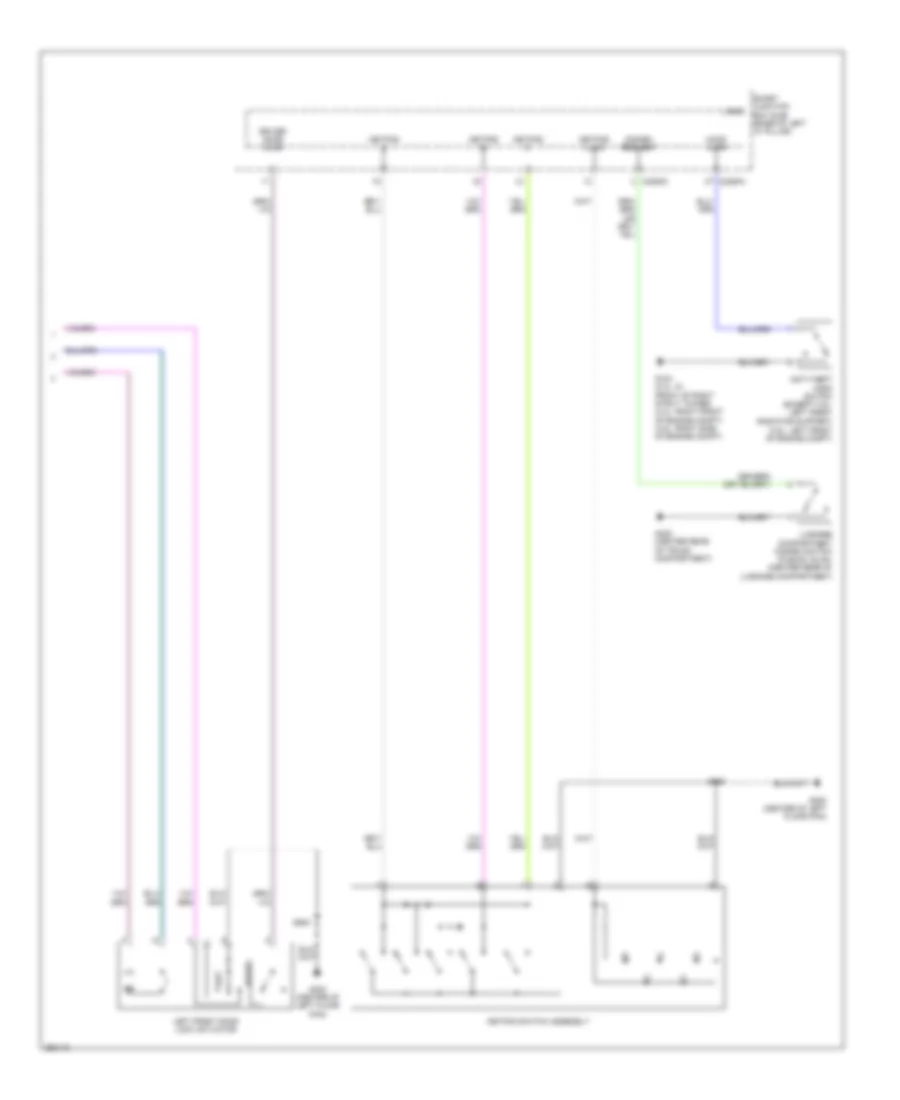 https://portal-diagnostov.com/license.html
Automotive Electricians Portal FZCO
Automotive Electricians Portal FZCO
https://portal-diagnostov.com/license.html
https://portal-diagnostov.com/license.html
Automotive Electricians Portal FZCO
Automotive Electricians Portal FZCOList of elements for Power Door Locks Wiring Diagram, with Memory (2 of 2) for Ford Fusion S 2007:
- (3.5l: left front of engine compt)
- Anti-theft hood switch (except 3.5l: left front radiator support)
- C2280a
- C2280c
- Disarm request
- Driver door ajar
- G104 (2.3l: in front of right strut tower) (3.0l: right front of engine compt) (3.5l: right side of engine compt)
- G300 (center of left floor pan)
- G400 (center rear of trunk compartment)
- Hood ajar
- Keypad a
- Keypad b
- Keypad c
- Keypad illum
- Keypad switch assembly
- Left front door lock actuator
- Logic
- Luggage compartment disarm switch (fusion, milan: (center rear of luggage compartment)
- Reset
- S500
- Set
- Smart junction box (sjb) (base of left "a" pillar)
Power Door Locks Wiring Diagram, without Memory (1 of 2) for Ford Fusion S 2007
 https://portal-diagnostov.com/license.html
Automotive Electricians Portal FZCO
Automotive Electricians Portal FZCO
https://portal-diagnostov.com/license.html
https://portal-diagnostov.com/license.html
Automotive Electricians Portal FZCO
Automotive Electricians Portal FZCOList of elements for Power Door Locks Wiring Diagram, without Memory (1 of 2) for Ford Fusion S 2007:
- (in body main harness, near breakout to c316)
- (in body main harness, near breakout to smart junction box (sjb)) s347
- (power seats harness, near breakout to smart junction box (sjb)) s324
- (power seats harness, near breakout to smart junction box (sjb)) s325
- Accessory delay relay
- C2280c
- C2280e
- Circuit breaker 30a
- Driver side door lock switch
- Fuse 15a
- Fuse 7.5a
- Fusion/ milan
- G203 (base of right "a" pillar)
- G300 (center of left floor pan)
- Hot at all times
- Interior lights system
- Left rear door lock actuator (in left rear door)
- Lock
- Lock all relay
- Logic
- Lr door ajar
- Mkz
- Pass door ajar
- Passenger side door lock switch
- Right front door lock actuator (in right front door)
- Right rear door lock actuator (in right rear door)
- Rr door ajar
- S328
- S342
- S500
- S601
- Smart junction box (sjb) (base of left "a" pillar)
- Trim lock
- Trim unlock
- Unlock
- Unlock all relay
- Unlock driver relay
Power Door Locks Wiring Diagram, without Memory (2 of 2) for Ford Fusion S 2007
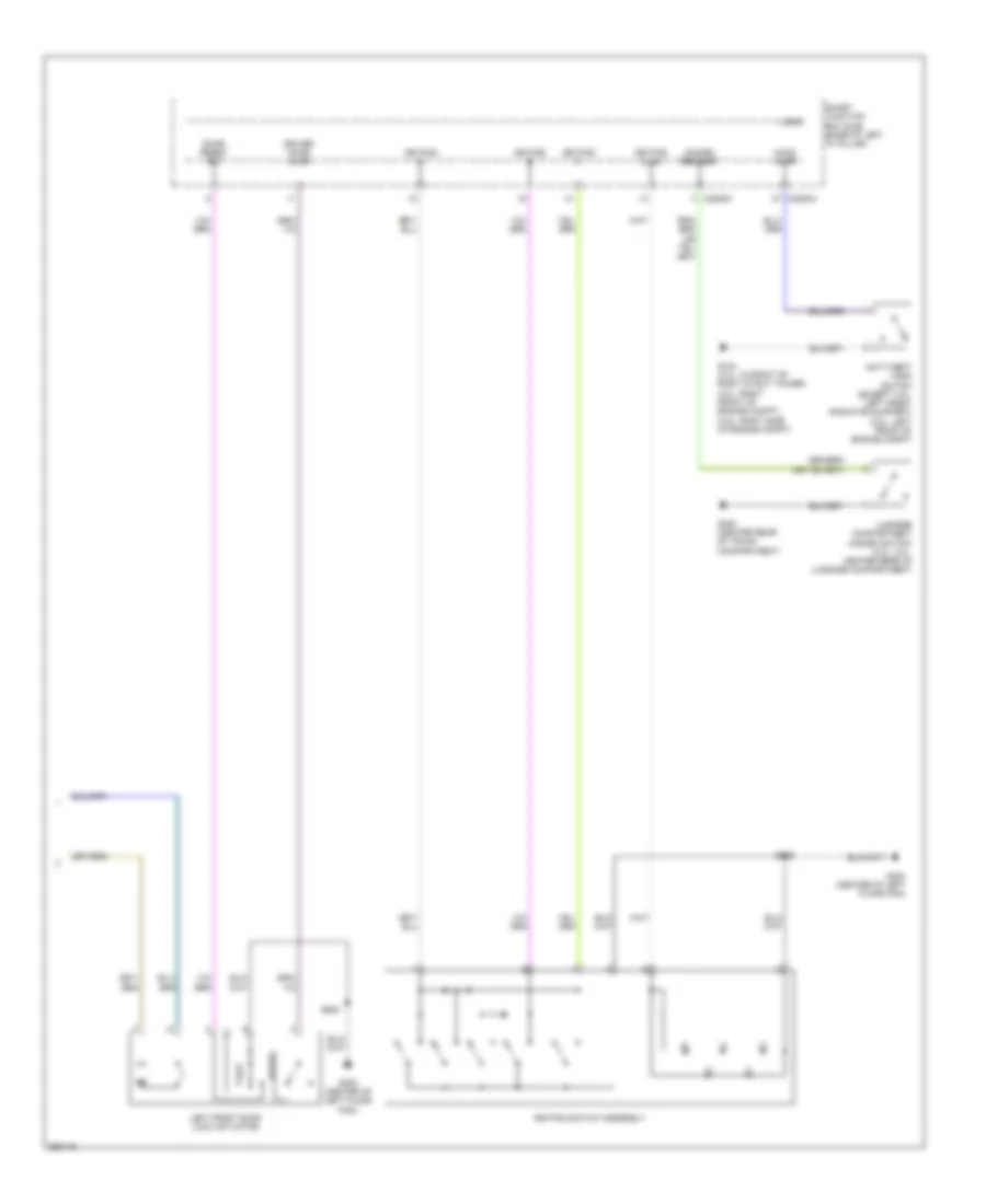 https://portal-diagnostov.com/license.html
Automotive Electricians Portal FZCO
Automotive Electricians Portal FZCO
https://portal-diagnostov.com/license.html
https://portal-diagnostov.com/license.html
Automotive Electricians Portal FZCO
Automotive Electricians Portal FZCOList of elements for Power Door Locks Wiring Diagram, without Memory (2 of 2) for Ford Fusion S 2007:
- Anti-theft hood switch (except 3.5l: left front radiator support) (3.5l: left front of engine compt)
- C2280a
- C2280c
- Disarm request
- Door reset sw
- Driver door ajar
- G104 (2.3l: in front of right strut tower) (3.0l: right front of engine compt) (3.5l: right side of engine compt)
- G300 (center of left floor pan)
- G400 (center rear of trunk compartment)
- Hood ajar
- Keypad a
- Keypad b
- Keypad c
- Keypad illum
- Keypad switch assembly
- Left front door lock actuator
- Logic
- Luggage compartment disarm switch (2.3l, 3.0l: center rear of luggage compartment)
- Reset
- S500
- Set
- Smart junction box (sjb) (base of left "a" pillar)
POWER MIRRORS
Electronic Day/Night Mirror Wiring Diagram for Ford Fusion S 2007
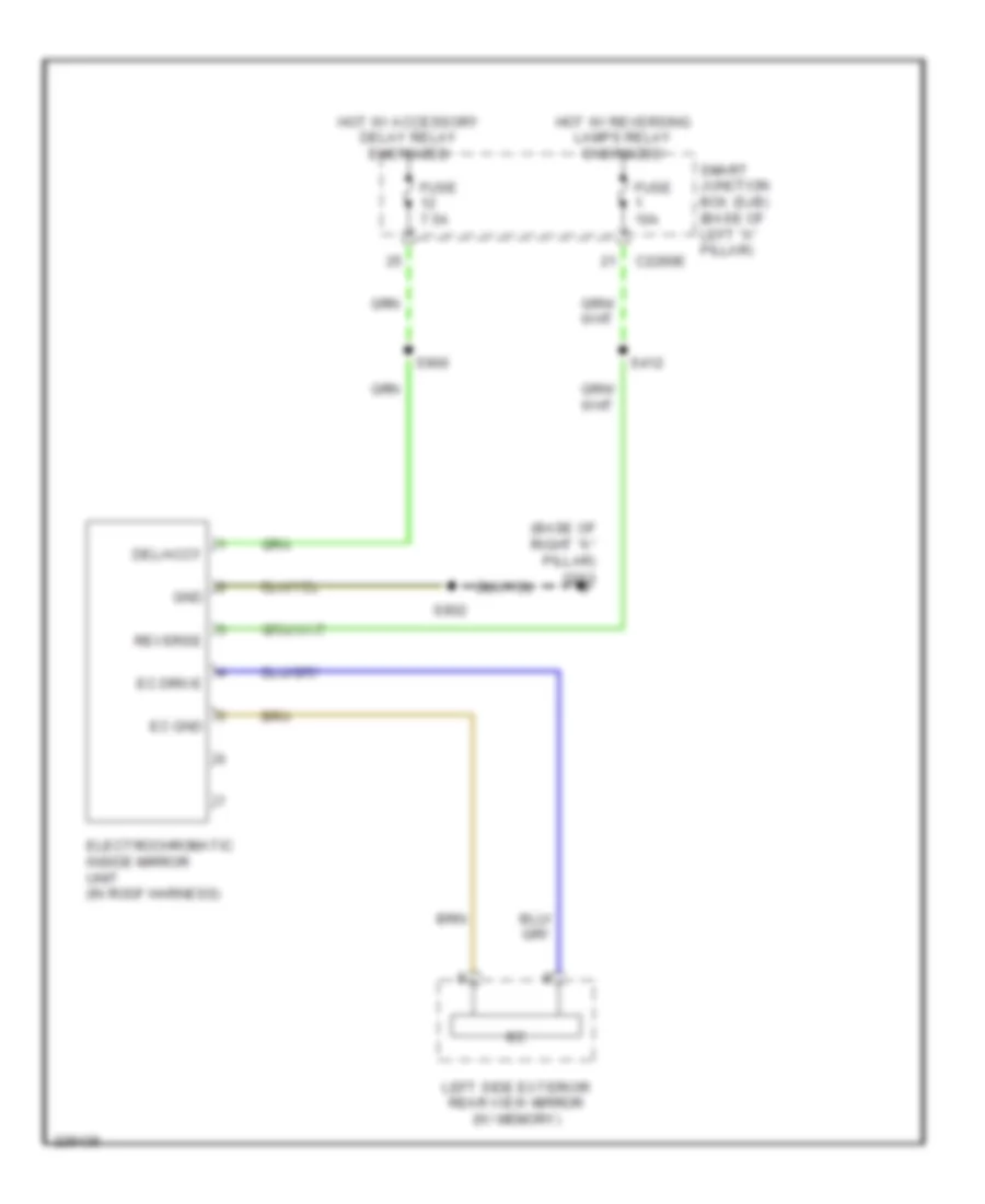 https://portal-diagnostov.com/license.html
Automotive Electricians Portal FZCO
Automotive Electricians Portal FZCO
https://portal-diagnostov.com/license.html
https://portal-diagnostov.com/license.html
Automotive Electricians Portal FZCO
Automotive Electricians Portal FZCOList of elements for Electronic Day/Night Mirror Wiring Diagram for Ford Fusion S 2007:
- (base of right "a" pillar)
- C2280e
- Del/accy
- Ec drive
- Ec gnd
- Electrochromatic inside mirror unit (in roof harness)
- Fuse 10a
- Fuse 7.5a
- G203
- Gnd
- Hot w/ accessory delay relay energized
- Hot w/ reversing lamps relay energized
- Left side exterior rear view mirror (w/ memory)
- Reverse
- S412
- S900
- S902
- Smart junction box (sjb) (base of left "a" pillar)
Heated Mirrors Wiring Diagram for Ford Fusion S 2007
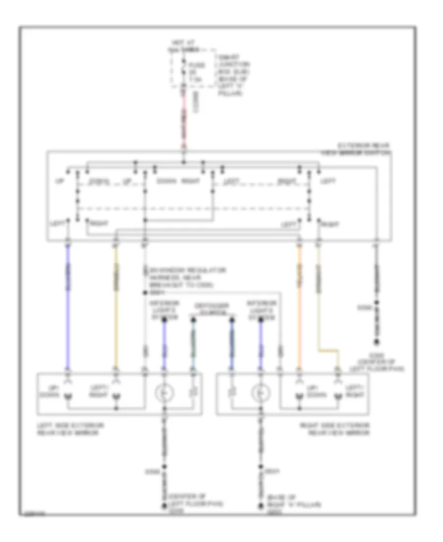 https://portal-diagnostov.com/license.html
Automotive Electricians Portal FZCO
Automotive Electricians Portal FZCO
https://portal-diagnostov.com/license.html
https://portal-diagnostov.com/license.html
Automotive Electricians Portal FZCO
Automotive Electricians Portal FZCOList of elements for Heated Mirrors Wiring Diagram for Ford Fusion S 2007:
- (base of right "a" pillar) g203
- (center of left floor pan) g300
- C2280e
- Defogger system
- Down
- Exterior rear view mirror switch
- Fuse 7.5a
- G300 (center of left floor pan)
- Hot at all times
- Interior lights system
- Left
- Left side exterior rear view mirror
- Left/ right
- Left/ right m
- Right
- Right side exterior rear view mirror
- Smart junction box (sjb) (base of left "a" pillar)
- Up/ down
- Up/ down m
Power Mirrors Wiring Diagram for Ford Fusion S 2007
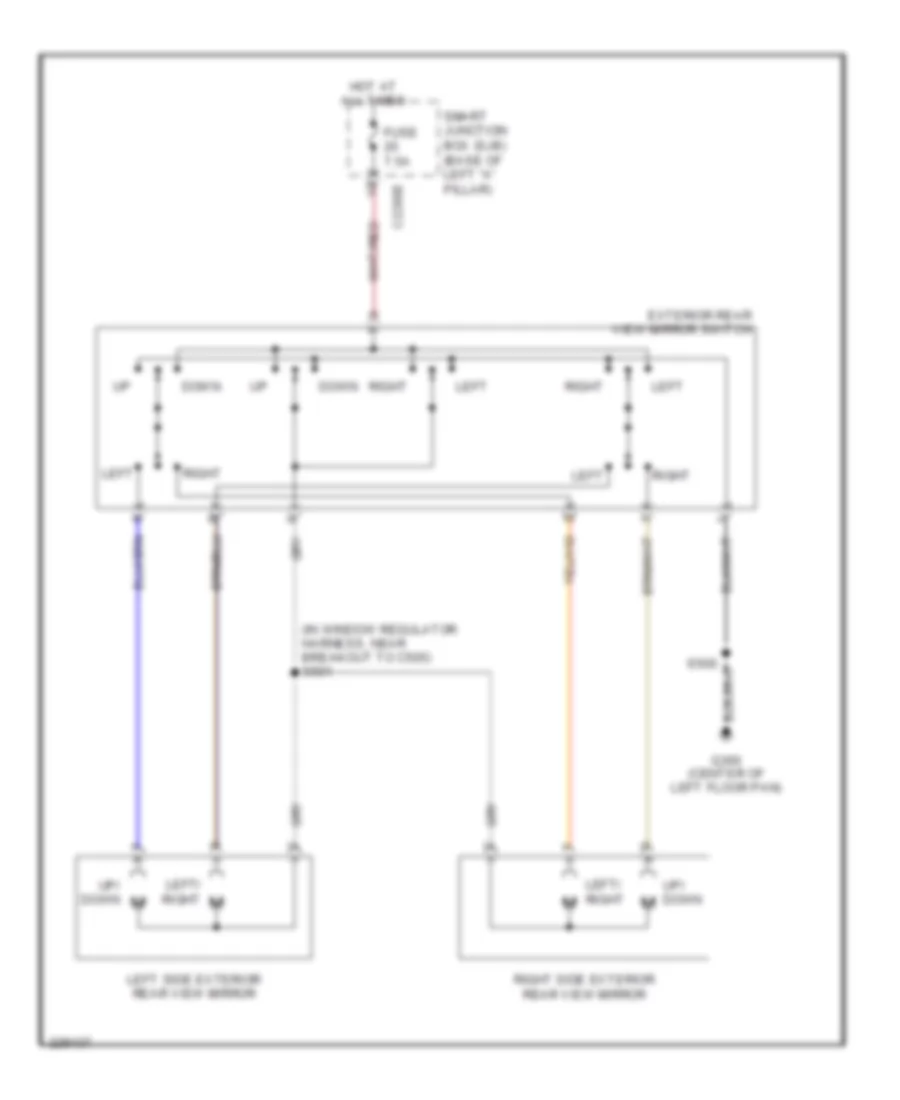 https://portal-diagnostov.com/license.html
Automotive Electricians Portal FZCO
Automotive Electricians Portal FZCO
https://portal-diagnostov.com/license.html
https://portal-diagnostov.com/license.html
Automotive Electricians Portal FZCO
Automotive Electricians Portal FZCOList of elements for Power Mirrors Wiring Diagram for Ford Fusion S 2007:
- (in window regulator harness, near breakout to c505) s501
- C2280e
- Down
- Exterior rear view mirror switch
- Fuse 7.5a
- G300 (center of left floor pan)
- Hot at all times
- Left
- Left side exterior rear view mirror
- Left/ right
- Left/ right m
- Right
- Right side exterior rear view mirror
- Smart junction box (sjb) (base of left "a" pillar)
- Up/ down
- Up/ down m
POWER SEATS
Climate Control Seats Wiring Diagram for Ford Fusion S 2007
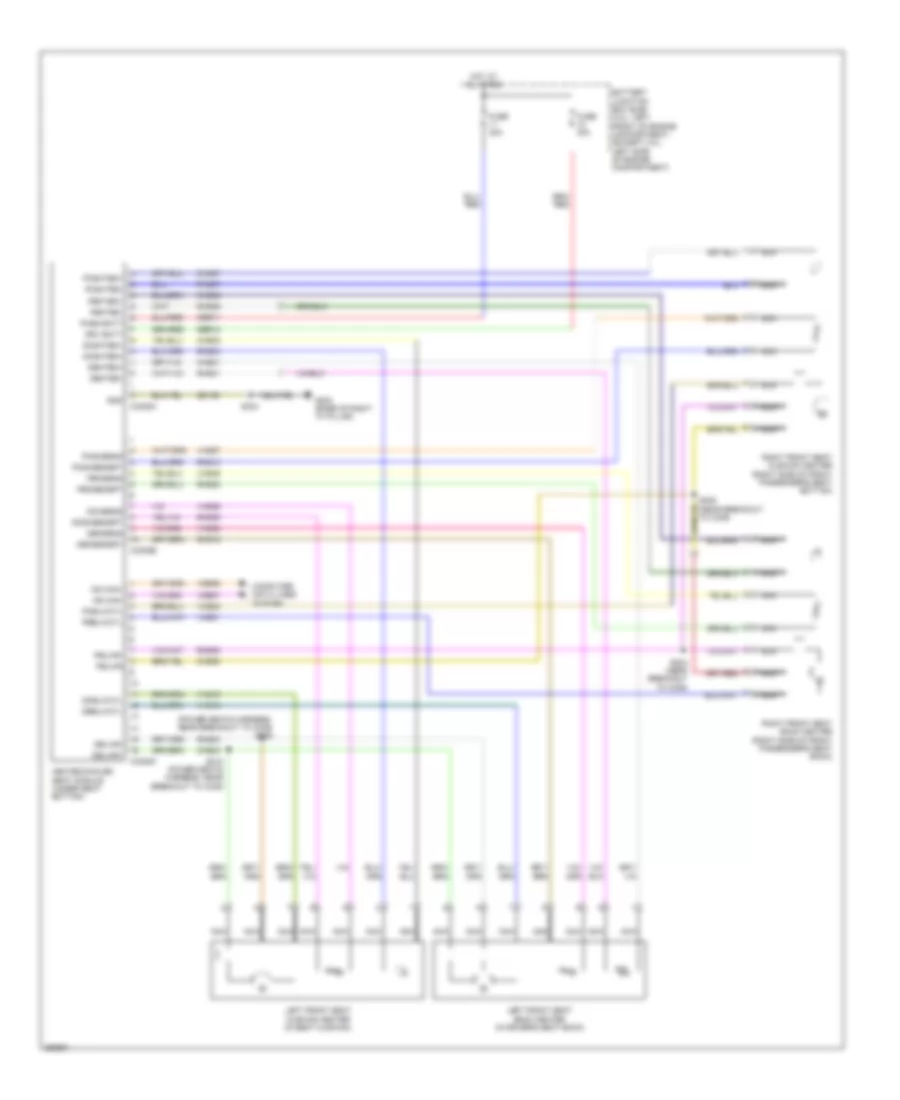 https://portal-diagnostov.com/license.html
Automotive Electricians Portal FZCO
Automotive Electricians Portal FZCO
https://portal-diagnostov.com/license.html
https://portal-diagnostov.com/license.html
Automotive Electricians Portal FZCO
Automotive Electricians Portal FZCOList of elements for Climate Control Seats Wiring Diagram for Ford Fusion S 2007:
- (power seats harness, near breakout to c339) s306
- Battery junction box (bjb) (3.0l: left front of engine compartment) (except 3.0l: left side of engine compartment)
- C3305a
- C3305b
- C3305c
- Chs01
- Chs02
- Chs03
- Chs06
- Chs07
- Chs08
- Computer data lines system
- Dbblwctl
- Dbksens
- Dbksensrt
- Dbkted+
- Dbkted-
- Dblwr+
- Dblwr-
- Dcblwctl
- Dchsens
- Dcshsensrt
- Dcshted+
- Drv batt
- Fuse 30a
- G203 (base of right "a" pillar)
- Gd139
- Gnd
- Heated/cooled seat module (under seat bottom)
- Hot at all times
- Left front seat back heater (in driver's seat back)
- Left front seat cushion heater (in seat cushion)
- Ms can+
- Ms can-
- Nca
- Pass batt
- Pbblwctl
- Pbksens
- Pbksensrt
- Pbkted+
- Pbkted-
- Pblwr
- Pblwr-
- Pcblwctl
- Pcshsens
- Pcshsensrt
- Pcshted+
- Pcshted-
- Rhs01
- Rhs02
- Rhs03
- Rhs05
- Rhs06
- Rhs07
- Rhs08
- Rhs10
- Rhs15
- Rhs20
- Right front seat back heater (right side of front passenger's seat back)
- Right front seat cushion heater (right side of front passenger's seat bottom)
- S303
- S304 (near breakout to c339)
- S305 (near breakout to c339)
- S310 (power seats harness, near breakout to c339)
- Sbb11
- Sbb12
- Vdb06
- Vdb07
- Vhs16
- Vhs18
- Vhs21
- Vhs23
- Vhs26
- Vhs27
- Vhs35
- Vhs36
Heated Seats Wiring Diagram, Single Zone Climate Control for Ford Fusion S 2007
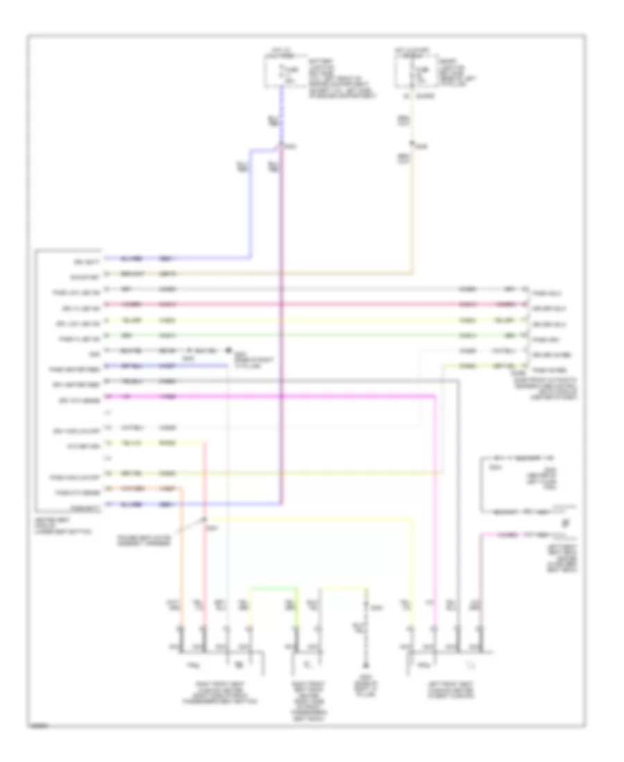 https://portal-diagnostov.com/license.html
Automotive Electricians Portal FZCO
Automotive Electricians Portal FZCO
https://portal-diagnostov.com/license.html
https://portal-diagnostov.com/license.html
Automotive Electricians Portal FZCO
Automotive Electricians Portal FZCOList of elements for Heated Seats Wiring Diagram, Single Zone Climate Control for Ford Fusion S 2007:
- (power seat motor assembly harness)
- Battery junction box (bjb) (3.0l: left front of engine compartment) (except 3.0l: left side of engine compartment)
- C2280e
- C228b
- Cbp19
- Chs02
- Chs04
- Chs07
- Chs09
- Chs13
- Chs14
- Chs29
- Chs30
- Driver hs req
- Driver hslo
- Drv batt
- Drv heater feed
- Drv hi led ind
- Drv high/low/off
- Drv low led ind
- Drv ntc sense
- Electronic automatic temperature control (eatc) module (center of dash)
- Fuse 10a
- Fuse 20a
- G203 (base of right "a" pillar)
- G300 (center of left floor pan)
- Gd139
- Gnd
- Heated seat module (under seat bottom)
- Hot at all times
- Hot in start or run
- Left front seat back heater (in driver's seat back)
- Left front seat cushion heater (in seat cushion)
- Nca
- Ntc return
- Pass batt
- Pass heater feed
- Pass hi led ind
- Pass high/low/off
- Pass hs req
- Pass hshi
- Pass hslo
- Pass low led ind
- Pass ntc sense
- Rhs05
- Right front seat back heater (right side of front passenger's seat back)
- Right front seat cushion heater (right side of front passenger's seat bottom)
- Run/start
- S301
- S302
- S303
- S304
- S329
- Sbb11
- Smart junction box (sjb) (base of left "a" pillar)
- Vhs26
- Vhs27
Power Seat Wiring Diagram, 6-Way Driver Seat for Ford Fusion S 2007
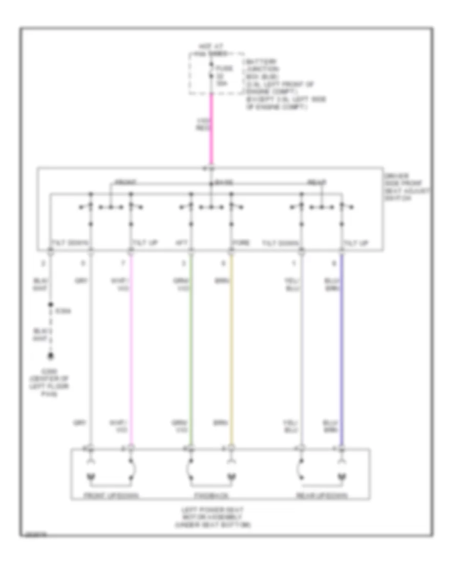 https://portal-diagnostov.com/license.html
Automotive Electricians Portal FZCO
Automotive Electricians Portal FZCO
https://portal-diagnostov.com/license.html
https://portal-diagnostov.com/license.html
Automotive Electricians Portal FZCO
Automotive Electricians Portal FZCOList of elements for Power Seat Wiring Diagram, 6-Way Driver Seat for Ford Fusion S 2007:
- Aft
- Base
- Battery junction box (bjb) (3.0l: left front of engine compt) (except 3.0l: left side of engine compt)
- Driver side front seat adjust switch
- Fore
- Front
- Front up/down
- Fuse 30a
- Fwd/back
- G300 (center of left floor pan)
- Hot at all times
- Left power seat motor assembly (under seat bottom)
- Rear
- Rear up/down
- S304
- Tilt down
- Tilt up
Power Seat Wiring Diagram, 6-Way passenger Seat for Ford Fusion S 2007
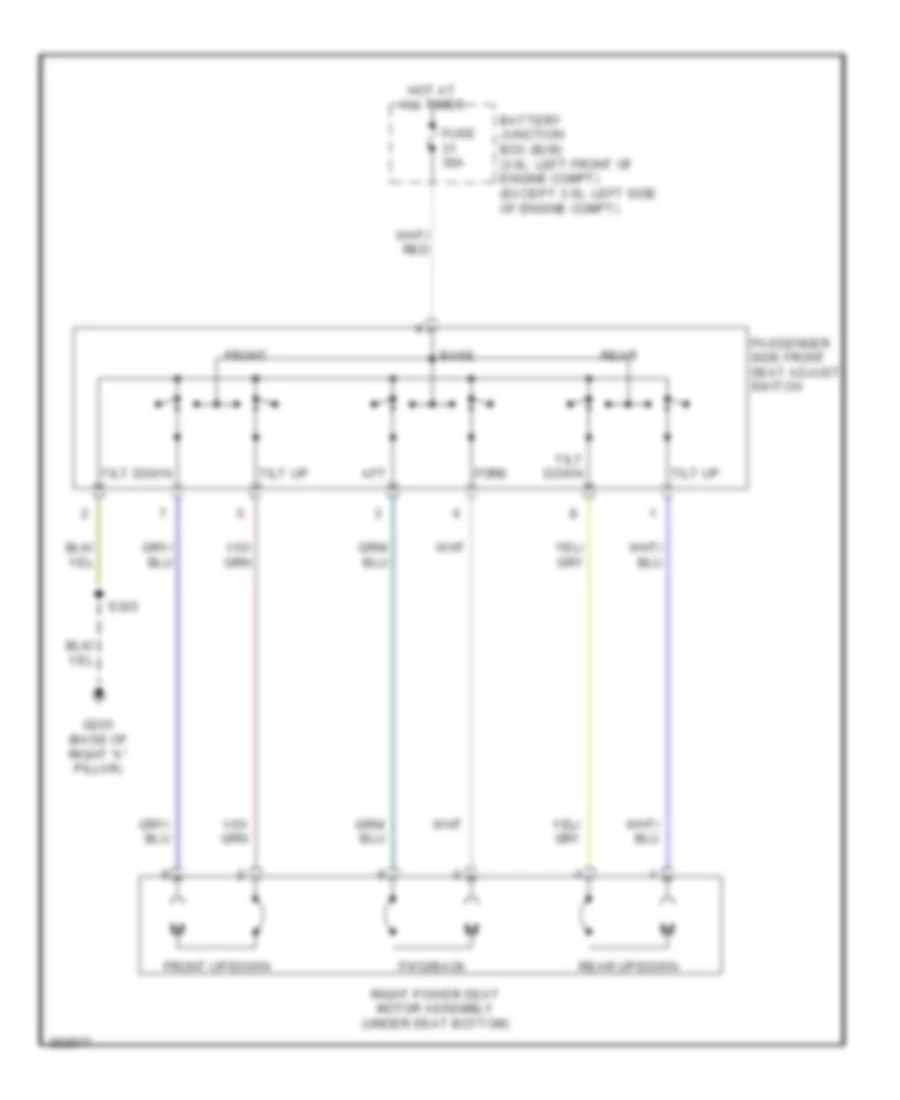 https://portal-diagnostov.com/license.html
Automotive Electricians Portal FZCO
Automotive Electricians Portal FZCO
https://portal-diagnostov.com/license.html
https://portal-diagnostov.com/license.html
Automotive Electricians Portal FZCO
Automotive Electricians Portal FZCOList of elements for Power Seat Wiring Diagram, 6-Way passenger Seat for Ford Fusion S 2007:
- Aft
- Base
- Battery junction box (bjb) (3.0l: left front of engine compt) (except 3.0l: left side of engine compt)
- Fore
- Front
- Front up/down
- Fuse 30a
- Fwd/back
- G203 (base of right "a" pillar)
- Hot at all times
- Passenger side front seat adjust switch
- Rear
- Rear up/down
- Right power seat motor assembly (under seat bottom)
- S303
- Tilt down
- Tilt up
Power Seat Wiring Diagram, 8-Way Driver Seat for Ford Fusion S 2007
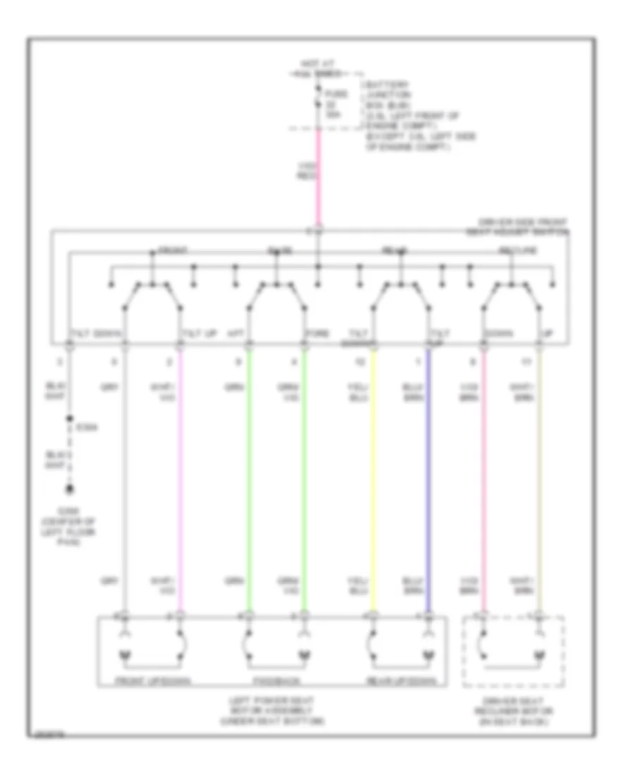 https://portal-diagnostov.com/license.html
Automotive Electricians Portal FZCO
Automotive Electricians Portal FZCO
https://portal-diagnostov.com/license.html
https://portal-diagnostov.com/license.html
Automotive Electricians Portal FZCO
Automotive Electricians Portal FZCOList of elements for Power Seat Wiring Diagram, 8-Way Driver Seat for Ford Fusion S 2007:
- Aft
- Base
- Battery junction box (bjb) (3.0l: left front of engine compt) (except 3.0l: left side of engine compt)
- Down
- Driver seat recliner motor (in seat back)
- Driver side front seat adjust switch
- Fore
- Front
- Front up/down
- Fuse 30a
- Fwd/back
- G300 (center of left floor pan)
- Hot at all times
- Left power seat motor assembly (under seat bottom)
- Rear
- Rear up/down
- Recline
- S304
- Tilt down
- Tilt up
Power Seat Wiring Diagram, 8-Way Passenger Seat for Ford Fusion S 2007
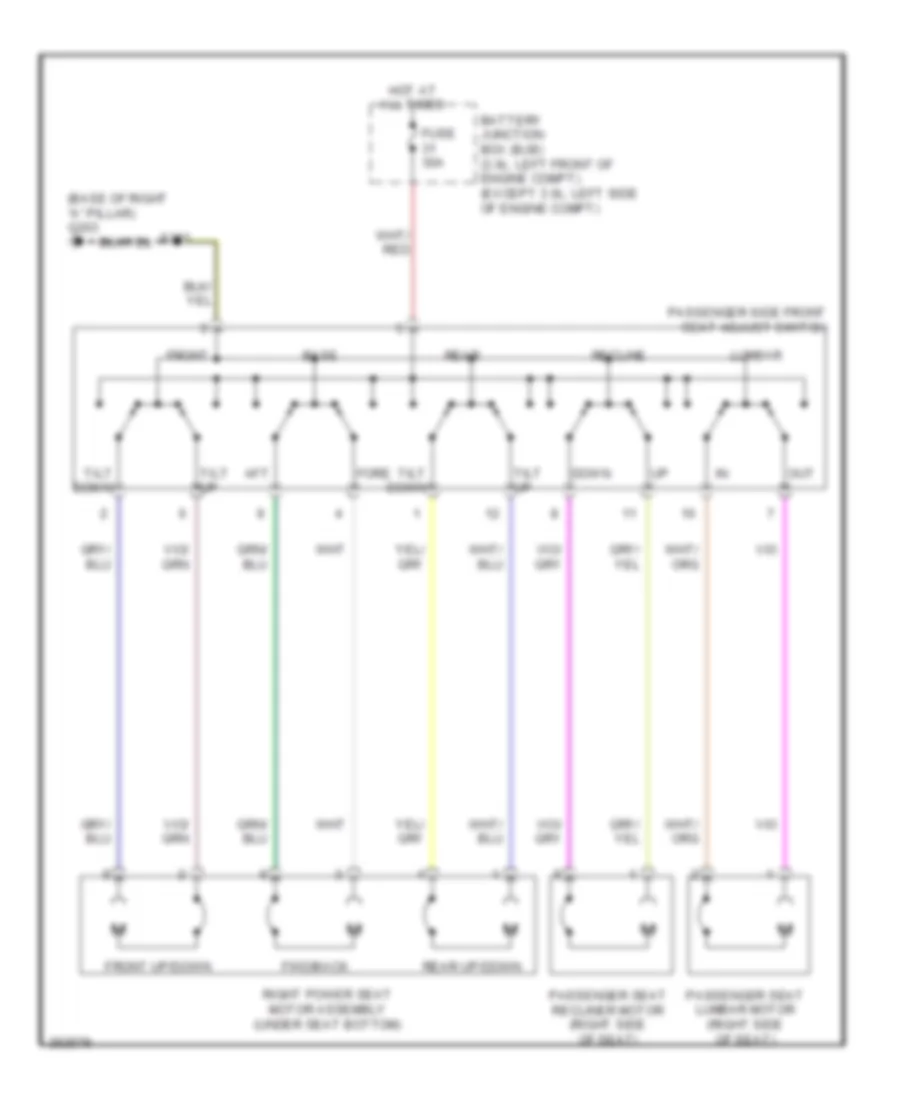 https://portal-diagnostov.com/license.html
Automotive Electricians Portal FZCO
Automotive Electricians Portal FZCO
https://portal-diagnostov.com/license.html
https://portal-diagnostov.com/license.html
Automotive Electricians Portal FZCO
Automotive Electricians Portal FZCOList of elements for Power Seat Wiring Diagram, 8-Way Passenger Seat for Ford Fusion S 2007:
- (base of right "a" pillar) g203
- Aft
- Base
- Battery junction box (bjb) (3.0l: left front of engine compt) (except 3.0l: left side of engine compt)
- Down
- Fore
- Front
- Front up/down
- Fuse 30a
- Fwd/back
- Hot at all times
- Lumbar
- Out
- Passenger seat lumbar motor (right side of seat)
- Passenger seat recliner motor (right side of seat)
- Passenger side front seat adjust switch
- Rear
- Rear up/down
- Recline
- Right power seat motor assembly (under seat bottom)
- S303
- Tilt down
- Tilt up
POWER TOP/SUNROOF
Power Top/Sunroof Wiring Diagram for Ford Fusion S 2007
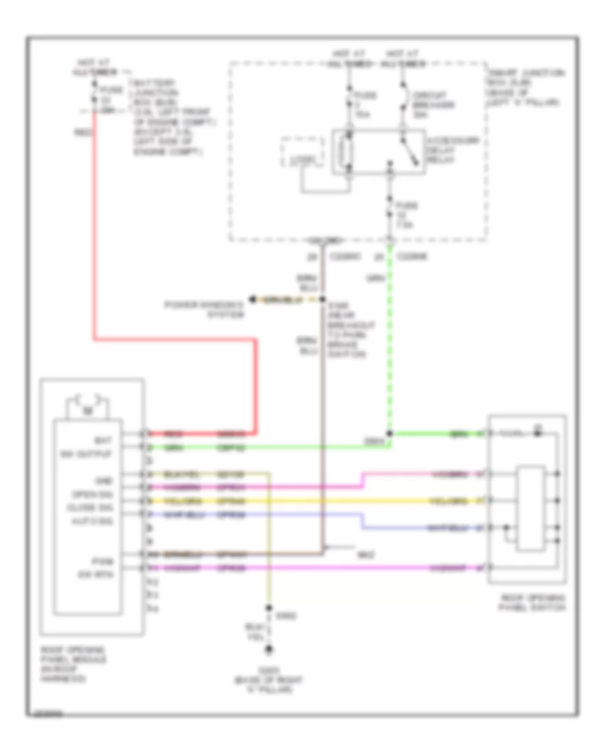 https://portal-diagnostov.com/license.html
Automotive Electricians Portal FZCO
Automotive Electricians Portal FZCO
https://portal-diagnostov.com/license.html
https://portal-diagnostov.com/license.html
Automotive Electricians Portal FZCO
Automotive Electricians Portal FZCOList of elements for Power Top/Sunroof Wiring Diagram for Ford Fusion S 2007:
- Accessory delay relay
- Auto sig
- Bat
- Battery junction box (bjb) (3.0l: left front of engine compt) (except 3.0l: left side of engine compt)
- C2280c
- C2280e
- Cbp02
- Circuit breaker 30a
- Close sig
- Cpr31
- Cpr38
- Cpr39
- Cpr40
- Cpw01
- Fuse 15a
- Fuse 20a
- Fuse 7.5a
- G203 (base of right "a" pillar)
- Gd139
- Gnd
- Go cmd
- Hot at all times
- Logic
- Mkz
- Open sig
- Power windows system
- Pwm
- Red
- Roof opening panel module (in roof harness)
- Roof opening panel switch
- S340 (near breakout to park brake switch)
- S900
- S902
- Sbb33
- Smart junction box (sjb) (base of left "a" pillar)
- Sw output
- Sw rtn
POWER WINDOWS
Power Windows Wiring Diagram for Ford Fusion S 2007
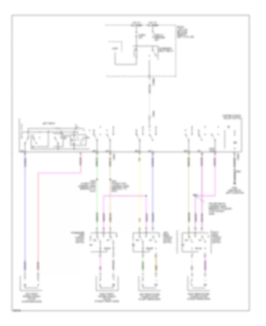 https://portal-diagnostov.com/license.html
Automotive Electricians Portal FZCO
Automotive Electricians Portal FZCO
https://portal-diagnostov.com/license.html
https://portal-diagnostov.com/license.html
Automotive Electricians Portal FZCO
Automotive Electricians Portal FZCOList of elements for Power Windows Wiring Diagram for Ford Fusion S 2007:
- (power seats harness, near breakout to smart junction box
- (sjb))
- Accessory delay relay
- Auto dn
- C2280e
- C504a
- C504b
- Circuit breaker 30a
- Fuse 3 15a
- G300 (center of left floor pan)
- Hot at all times
- Left front
- Left front power window motor (in driver's door)
- Left rear power window motor (in left rear door)
- Left rear window adjust switch
- Lock out
- Logic
- Master window adjust switch
- Passenger side window adjust switch
- Right front power window motor (in right front door)
- Right rear power window motor (in right rear door)
- Right rear window adjust switch
- S321
- S326 (in body main harness, near breakout to c510)
- S327 (in body main harness, near breakout to c510)
- S500
- Smart junction box (sjb) (base of left "a" pillar)
RADIO
Audiophile Sound Radio Wiring Diagram (1 of 2) for Ford Fusion S 2007
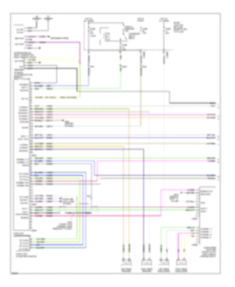 https://portal-diagnostov.com/license.html
Automotive Electricians Portal FZCO
Automotive Electricians Portal FZCO
https://portal-diagnostov.com/license.html
https://portal-diagnostov.com/license.html
Automotive Electricians Portal FZCO
Automotive Electricians Portal FZCOList of elements for Audiophile Sound Radio Wiring Diagram (1 of 2) for Ford Fusion S 2007:
- (or cme35)
- Accessory delay relay
- Am ant
- Am antenna
- Ant
- Ant pwr
- Ant pwr c4194a
- Antenna
- Antenna (late production) (base of right "c" pillar)
- Antenna module (early production) (right rear of trunk)
- Audio jack (in center console)
- Audio shield
- Audio unit (center of dash)
- Aux1 +
- Aux1 -
- Batt +
- C2280b
- C2280e
- C290a
- C290c
- C290d
- C466a
- C466b
- Cbp02
- Cbp13
- Channel 1 +
- Channel 1 -
- Channel 2 +
- Channel 2 -
- Circuit breaker 30a
- Cls38
- Cme35
- Cme44
- Coax
- Computer data lines system
- Def pwr c4194b
- Defogger system
- Dme22
- Dme45
- Enable
- Enable clip
- Fm ant
- Fm antenna
- Fuse 20a
- Fuse 7.5a
- G200 (center of dash)
- G402 (base of right "c" pillar)
- Gd114
- Gnd audio
- Hot at all times
- Hot in start
- Input +
- Input -
- Left rear speaker
- Left rear subwoofer
- Lf spkr +
- Lf spkr -
- Logic
- Lr spkr +
- Lr spkr -
- Ms can +
- Ms can -
- Nca
- Pwr
- Pwr gnd
- Rf spkr +
- Rf spkr -
- Right rear speaker
- Right rear subwoofer
- Rme07
- Rme09
- Rme10
- Rme12
- Rme22
- Rme24
- Rme41
- Rme42
- Rme45
- Rme46
- Rr spkr +
- Rr spkr -
- Run/acc
- S226
- S231
- S232
- S242 (in body main harness, near breakout to c237)
- Sat ant
- Sbp11
- Shield
- Smart junction box (sjb) (base of left "a" pillar)
- Sme23
- St in 2l(+)
- St in 2l(-)
- St in 2r(+)
- St in 2r(-)
- Start
- Stereo 1l(+)
- Stereo 1l(-)
- Stereo 1r(+)
- Stereo 1r(-)
- Subwoofer amplifier (fusion, milan: right side of luggage compt)
- Sw 12v
- Swc 1 +
- Swc 1 rtn
- Vdb06
- Vdb07
- Vme07
- Vme09
- Vme10
- Vme12
- Vme14
- Vme22
- Vme41
- Vme42
- Vme45
- Vme46
Audiophile Sound Radio Wiring Diagram (2 of 2) for Ford Fusion S 2007
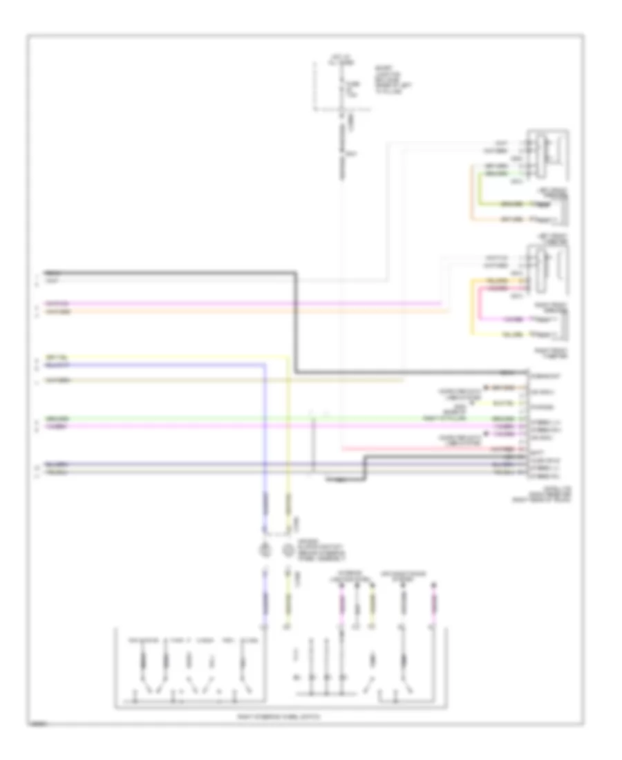 https://portal-diagnostov.com/license.html
Automotive Electricians Portal FZCO
Automotive Electricians Portal FZCO
https://portal-diagnostov.com/license.html
https://portal-diagnostov.com/license.html
Automotive Electricians Portal FZCO
Automotive Electricians Portal FZCOList of elements for Audiophile Sound Radio Wiring Diagram (2 of 2) for Ford Fusion S 2007:
- Air bag sliding contact (behind steering wheel assembly)
- Air conditioning system
- Audio shld
- Batt
- C218a
- C218b
- C2280e
- C513
- C523
- C612
- C613
- Coax
- Computer data lines system
- Dcbias/ant
- Fuse 7.5a
- G402 (base of right "c" pillar)
- Hot at all times
- Interior lights system
- Left front speaker
- Left front tweeter
- Media
- Ms can(+)
- Ms can(-)
- Nca
- Pwr gnd
- Right front speaker
- Right front tweeter
- Right steering wheel switch
- S341
- Satellite radio receiver (right rear of trunk)
- Seek +
- Seek -
- Smart junction box (sjb) (base of left "a" pillar)
- Stereo l(+)
- Stereo l(-)
- Stereo r(+)
- Stereo r(-)
- Temp +
- Temp -
- Vol +
- Vol -
Base Radio Wiring Diagram for Ford Fusion S 2007
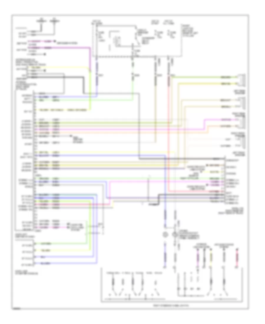 https://portal-diagnostov.com/license.html
Automotive Electricians Portal FZCO
Automotive Electricians Portal FZCO
https://portal-diagnostov.com/license.html
https://portal-diagnostov.com/license.html
Automotive Electricians Portal FZCO
Automotive Electricians Portal FZCOList of elements for Base Radio Wiring Diagram for Ford Fusion S 2007:
- (or cme35)
- Accessory delay relay
- Air bag sliding contact (behind steering wheel assembly)
- Air conditioning system
- Am ant
- Am antenna
- Ant
- Ant pwr
- Ant pwr c4194a
- Antenna
- Antenna (late procuction) (right rear of trunk)
- Antenna module (early production) (mkz: right rear of trunk)
- Audio jack (in center console)
- Audio shld
- Audio unit (center of dash)
- Batt
- Batt +
- C218a
- C218b
- C2280b
- C2280e
- C290a
- C290c
- Cbp02
- Cbp13
- Circuit breaker 30a
- Cls38
- Cme35
- Cme44
- Coax
- Computer data lines system
- Dcbias/ant
- Def pwr c4194b
- Defogger system
- Dme45
- Fm ant
- Fm antenna
- Fuse 20a
- Fuse 7.5a
- G200 (center of dash)
- G402 (base of right "c" pillar)
- Gd114
- Hot at all times
- Hot in start
- Interior lights system
- Left front speaker
- Left rear speaker
- Lf spkr +
- Lf spkr -
- Logic
- Lr spkr +
- Lr spkr -
- Media
- Ms can +
- Ms can -
- Ms can(+)
- Ms can(-)
- Nca
- Pwr gnd
- Rf spkr +
- Rf spkr -
- Right front speaker
- Right rear speaker
- Right steering wheel switch
- Rme07
- Rme09
- Rme10
- Rme12
- Rme24
- Rme41
- Rme42
- Rme45
- Rme46
- Rr spkr +
- Rr spkr -
- Run/acc
- S226
- S231
- S232
- S341
- Sat ant
- Satellite radio receiver (right rear of trunk)
- Sbp11
- Seek +
- Seek -
- Shield
- Smart junction box (sjb) (base of left "a" pillar)
- St in 2l(+)
- St in 2l(-)
- St in 2r(+)
- St in 2r(-)
- Start
- Stereo 1l(+)
- Stereo 1l(-)
- Stereo 1r(+)
- Stereo 1r(-)
- Stereo l(+)
- Stereo l(-)
- Stereo r(+)
- Stereo r(-)
- Sw 12v
- Swc 1 +
- Swc 1 rtn
- Temp +
- Temp -
- Vdb06
- Vdb07
- Vme07
- Vme09
- Vme10
- Vme12
- Vme14
- Vme41
- Vme42
- Vme45
- Vme46
- Vol +
- Vol -
SHIFT INTERLOCK
Shift Interlock Wiring Diagram for Ford Fusion S 2007
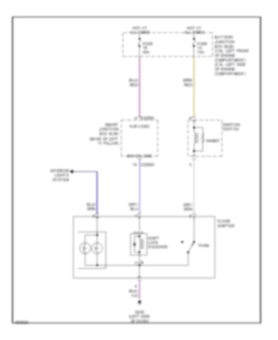 https://portal-diagnostov.com/license.html
Automotive Electricians Portal FZCO
Automotive Electricians Portal FZCO
https://portal-diagnostov.com/license.html
https://portal-diagnostov.com/license.html
Automotive Electricians Portal FZCO
Automotive Electricians Portal FZCOList of elements for Shift Interlock Wiring Diagram for Ford Fusion S 2007:
- (base of left "a" pillar)
- A (+)
- B (-)
- Battery junction box (bjb) (3.0l: left front of engine compartment) (2.3l: left side of engine compartment)
- Bsi sol cmd
- C2280a
- C2280c
- Floor
- Fuse 15a
- Fuse 40a
- G202 (left side of dash)
- Hot at all times
- Ignition switch
- Inhibit
- Interior lights system
- Park
- Shift lock solenoid
- Shifter
- Sjb logic
- Smart junction box (sjb)
STARTING/CHARGING
Charging Wiring Diagram for Ford Fusion S 2007
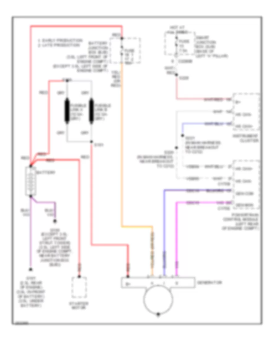 https://portal-diagnostov.com/license.html
Automotive Electricians Portal FZCO
Automotive Electricians Portal FZCO
https://portal-diagnostov.com/license.html
https://portal-diagnostov.com/license.html
Automotive Electricians Portal FZCO
Automotive Electricians Portal FZCOList of elements for Charging Wiring Diagram for Ford Fusion S 2007:
- (or red)
- Battery
- Battery junction box (bjb) (3.0l: left front of engine compt) (except 3.0l: left side of engine compt)
- C175b
- C175e
- C2280b
- Cdc10
- Cdc15
- Early production
- Fuse 10a
- Fuse 7.5a
- G100 (except 3.5l: left front strut tower) (3.5l: left side of engine compt, near battery junction box (bjb))
- G101 (2.3l: rear of engine) (3.0l: in front of battery) (3.5l: under battery)
- Gen com
- Gen mon
- Generator
- Hot at all times
- Hs can+
- Hs can-
- Instrument cluster
- Late production
- Powertrain control module (left rear of engine compt)
- Red
- S100
- S101
- S220 (in main harness, near breakout to c212)
- S221 (in main harness, near breakout to c212)
- S229
- Smart junction box (sjb) (base of left "a" pillar)
- Starter motor
- Vdb04
- Vdb05
Starting Wiring Diagram for Ford Fusion S 2007
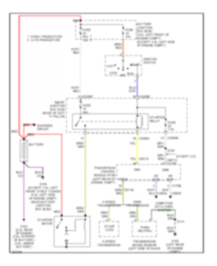 https://portal-diagnostov.com/license.html
Automotive Electricians Portal FZCO
Automotive Electricians Portal FZCO
https://portal-diagnostov.com/license.html
https://portal-diagnostov.com/license.html
Automotive Electricians Portal FZCO
Automotive Electricians Portal FZCOList of elements for Starting Wiring Diagram for Ford Fusion S 2007:
- (left rear of engine compt)
- 6 speed transmission
- Acc
- Battery
- Battery junction box (bjb) (3.0l: left front of engine compt) (except 3.0l: left side of engine compt)
- C175b
- C2280a
- C2280b
- C2280f
- Charging circuit
- Computer data lines system
- Early production late production
- Except 2.3l
- Fnr5 transmission
- Fuse 15a
- Fuse 30a
- Fuse 60a 10a
- Fuse 7.5a
- G100 (except 3.5l: left front strut tower) (3.5l: left side of engine compt, near battery junction box (bjb))
- G101 (2.3l: rear of engine) (3.0l: in front of battery) (3.5l: under battery)
- G102 (left rear of engine compt)
- Hs can+
- Hs can-
- Ignition switch
- Lock
- Off
- Park/ neutral
- Powertrain control module (pcm)
- Red
- Run
- S111
- S232
- Smart junction box (sjb) (base of left "a" pillar)
- Smc
- Smr
- Start
- Start lock
- Starter motor
- Starter relay
- Transmission range sensor (left side of dash)
- Trsw
- Vdb04
- Vdb05
SUPPLEMENTAL RESTRAINTS
Supplemental Restraints Wiring Diagram (1 of 2) for Ford Fusion S 2007
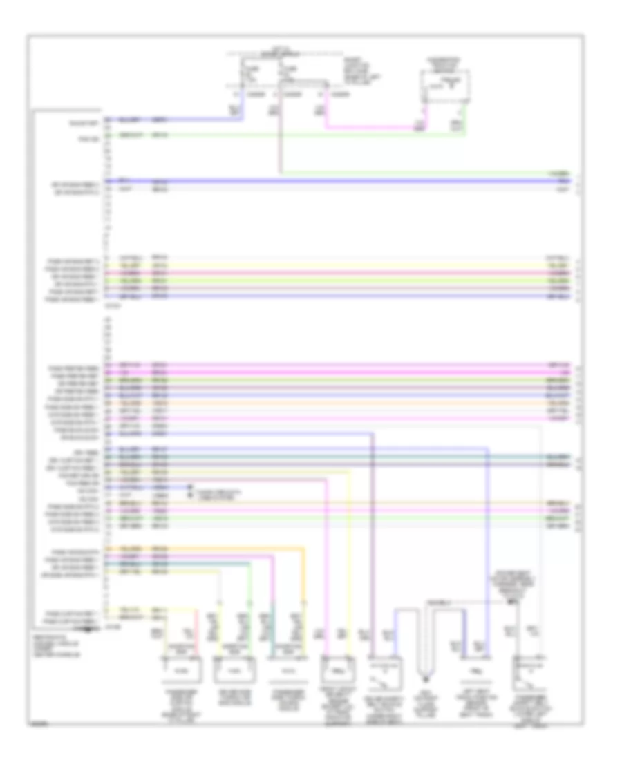 https://portal-diagnostov.com/license.html
Automotive Electricians Portal FZCO
Automotive Electricians Portal FZCO
https://portal-diagnostov.com/license.html
https://portal-diagnostov.com/license.html
Automotive Electricians Portal FZCO
Automotive Electricians Portal FZCOList of elements for Supplemental Restraints Wiring Diagram (1 of 2) for Ford Fusion S 2007:
- (power seat motor assembly harness, near breakout to c313) s300
- C2280b
- C2280e
- C310a
- C310b
- Case gnd
- Cbp21
- Computer data lines system
- Cr101
- Cr102
- Cr103
- Cr104
- Cr105
- Cr106
- Cr109
- Cr111
- Cr116
- Cr120
- Cr121
- Cr201
- Cr203
- Dr air bag feed 1
- Dr air bag feed 2
- Dr air bag rtn 1
- Dr air bag rtn 2
- Dr buckle sw
- Dr preten feed
- Dr preten ret
- Dr side air bag rtn 1
- Driver safety belt buckle switch (under right side of seat)
- Driver side thorax air bag module
- Drv curtain feed 1
- Drv curtain ret 1
- Drv feed
- Dvr side sn feed 1
- Dvr side sn feed 2
- Dvr side sn rtn 1
- Dvr side sn rtn 2
- Fcs feed dr
- Fcs return dr
- Front impact severity sensor (except 3.5l: at front radiator support)
- Fuse 7.5a
- G301 (on right floor support pillar)
- Hazard/pad/ traction switch
- Hot in start or run
- Hs can+
- Hs can-
- Left seat track position sensor (front of seat track)
- Pad ind
- Pass air bag feed 1
- Pass air bag feed 2
- Pass air bag ret 2
- Pass air bag ret1
- Pass air bag rtn
- Pass buckle sw
- Pass curtain feed 1
- Pass curtain ret 1
- Pass preten feed
- Pass preten ret
- Pass side sn feed 1
- Pass side sn feed 2
- Pass side sn rtn 1
- Pass side sn rtn 2
- Passenger safety belt buckle switch (lower left side of seat track)
- Passenger side air curtain module (base of right "c" pillar)
- Passenger side thorax air bag module
- Restraints control module (under center console)
- Rr101
- Rr102
- Rr103
- Rr104
- Rr105
- Rr106
- Rr109
- Rr111
- Rr120
- Rr121
- Rr129
- Rr131
- Rr132
- Rr133
- Rr134
- Rr137
- Run/start
- Shorting bar
- Smart junction box (sjb) (base of left "a" pillar)
- Vdb04
- Vdb05
- Vr213
- Vr217
- Vr218
- Vr219
- Vr220
Supplemental Restraints Wiring Diagram (2 of 2) for Ford Fusion S 2007
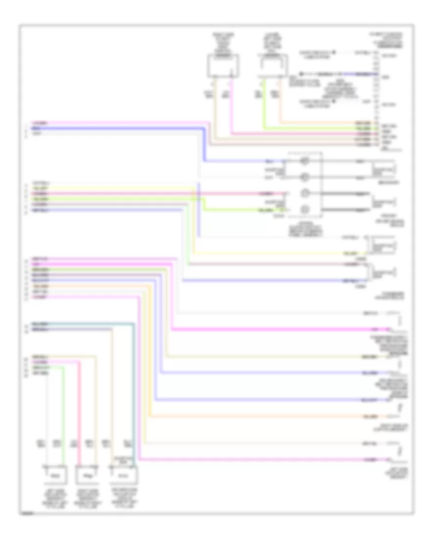 https://portal-diagnostov.com/license.html
Automotive Electricians Portal FZCO
Automotive Electricians Portal FZCO
https://portal-diagnostov.com/license.html
https://portal-diagnostov.com/license.html
Automotive Electricians Portal FZCO
Automotive Electricians Portal FZCOList of elements for Supplemental Restraints Wiring Diagram (2 of 2) for Ford Fusion S 2007:
- (in seat cushion) occupant classification sensor (ocs)
- (lower left side of seat) left side rail sensor
- (right side of seat track) right side rail sensor
- Air bag sliding contact (behind steering wheel assembly)
- C218a
- C256a
- C256b
- Computer data lines system
- Driver air bag module
- Driver safety belt retractor pretensioner (base of "b" pillar)
- Driver's side air curtain module (base of left "c" pillar)
- Feed
- G301 (on right floor support pillar)
- Gnd
- Hs can+
- Hs can-
- Ign
- Left side air curtain sensor 1
- Left side air curtain sensor 2 (base of left "c" pillar)
- Nca
- Passenger air bag module
- Passenger safety belt retractor pretensioner (base of right "b" pillar)
- Primary
- Return
- Right side air curtain sensor 1
- Right side air curtain sensor 2 (base of right "c" pillar)
- S300 (power seat motor assembly harness, near breakout to c313)
- Secondary
- Shorting bar
TRANSMISSION
A/T Wiring Diagram, 6 Speed A/T for Ford Fusion S 2007
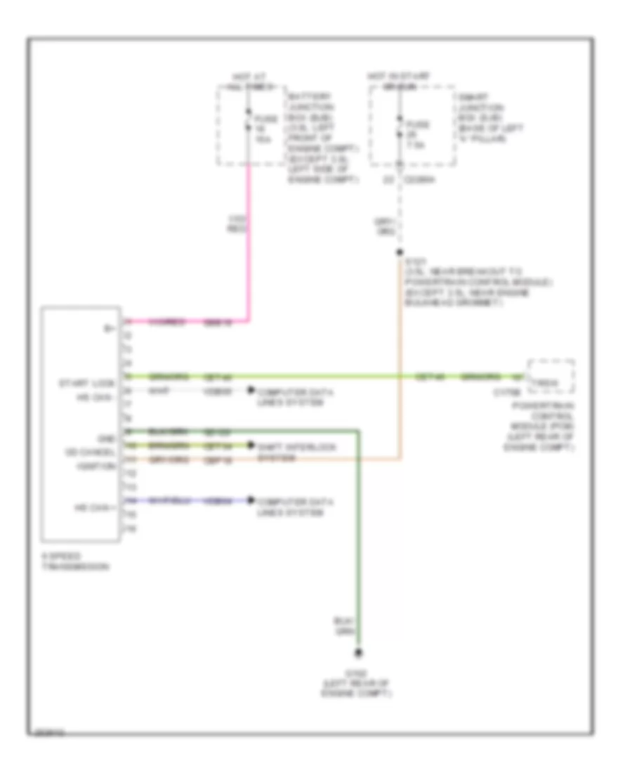 https://portal-diagnostov.com/license.html
Automotive Electricians Portal FZCO
Automotive Electricians Portal FZCO
https://portal-diagnostov.com/license.html
https://portal-diagnostov.com/license.html
Automotive Electricians Portal FZCO
Automotive Electricians Portal FZCOList of elements for A/T Wiring Diagram, 6 Speed A/T for Ford Fusion S 2007:
- 6 speed transmission
- Battery junction box (bjb) (3.0l: left front of engine compt) (except 3.0l: left side of engine compt)
- C175b
- C2280a
- Cbp18
- Cet34
- Cet40
- Computer data lines system
- Fuse 15a
- Fuse 7.5a
- G102 (left rear of engine compt)
- Gd120
- Gnd
- Hot at all times
- Hot in start or run
- Hs can +
- Hs can -
- Ignition
- Od cancel
- Powertrain control module (pcm) (left rear of engine compt)
- S121 (3.5l: near breakout to powertrain control module) (except 3.5l: near engine bulkhead grommet)
- Sbb16
- Shift interlock system
- Smart junction box (sjb) (base of left "a" pillar)
- Start lock
- Trsw
- Vdb04
- Vdb05
A/T Wiring Diagram, FNR5 for Ford Fusion S 2007
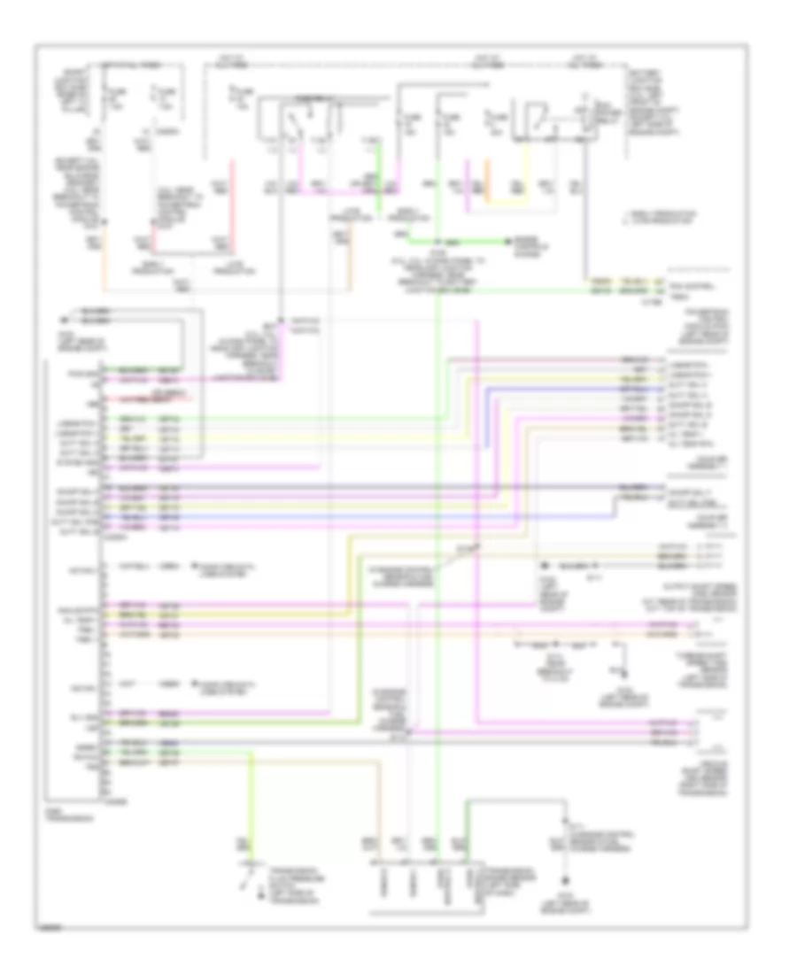 https://portal-diagnostov.com/license.html
Automotive Electricians Portal FZCO
Automotive Electricians Portal FZCO
https://portal-diagnostov.com/license.html
https://portal-diagnostov.com/license.html
Automotive Electricians Portal FZCO
Automotive Electricians Portal FZCOList of elements for A/T Wiring Diagram, FNR5 for Ford Fusion S 2007:
- (3.0l: near breakout to powertrain control module) s127
- (except 3.5l: near engine bulkhead grommet) (3.5l: near breakout to powertrain control module) s121
- (in engine control sensor & fuel charge harness)
- (or sbb23) sbp07
- +bb
- Analog rtn oil temp + trev - trev +
- Battery junction box (bjb) (3.0l: left front of engine compt) (except 3.0l: left side of engine compt)
- C175b
- C2280a
- C2352b
- Ce302
- Ce613
- Cet18
- Cet19
- Cet37
- Cet40
- Cet42
- Cet43
- Cet44
- Cet45
- Cet46
- Computer data lines system
- Coupler assembly 1
- Coupler assembly 2
- Duty sol a
- Duty sol b
- Duty sol c
- Duty sol pcb
- Early production
- Early production late production
- Engine controls system
- Fnr5 relay
- Fnr5 transmission
- Fuse 10a
- Fuse 15a
- Fuse 40a
- Fuse 7.5a
- G102 (left rear of engine compt)
- Gd120
- Hot at all times
- Hs can +
- Hs can -
- Late production
- Linear pca +
- Linear pca -
- Linear pca - linear pca + duty sol c duty sol a system gnd +b2
- Nca
- Oil temp +
- Oil temp rtn
- On/off sol d
- On/off sol e
- On/off sol f
- On/off sol f on/off sol e on/off sol d duty sol pcb duty sol b c2352a
- Output shaft speed (oss) sensor (a/t: rear of transmission) (m/t: top of transmission)
- Park/ neutral a
- Park/ neutral f
- Pcm control
- Pcm power relay
- Powertrain control module (pcm) (left rear of engine compt)
- Pwr gnd +b
- Range b
- Range c
- Re406
- Ret33
- Rly gnd vsp
- S110
- S111
- S111 (in engine control sensor & fuel charge harness)
- S112
- S114 (near breakout to c134)
- S129 (2.3l, 3.0l: in dash panel to headlamp junction harness, near breakout to battery junction box (bjb))
- S210 (2.3l, 3.0l: in dash panel to headlamp junction harness, near breakout to smart junction box (sjb))
- Sgrev ps fwc trs
- Smart junction box (sjb) (base of left "a" pillar)
- Transmission fluid pressure switch (left side of transmission)
- Transmission range sensor (left side of dash)
- Trsw
- Turbine shaft speed (tss) sensor (left side of transmission)
- Vdb04
- Vdb05
- Ve822
- Vehicle shaft speed (iss) sensor (right side of transmission)
- Vet13
- Vet14
- Vet15
- Vet26
- Vet27
- Vet28
- Vet33
TRUNK, TAILGATE, FUEL DOOR
Trunk Release Wiring Diagram for Ford Fusion S 2007
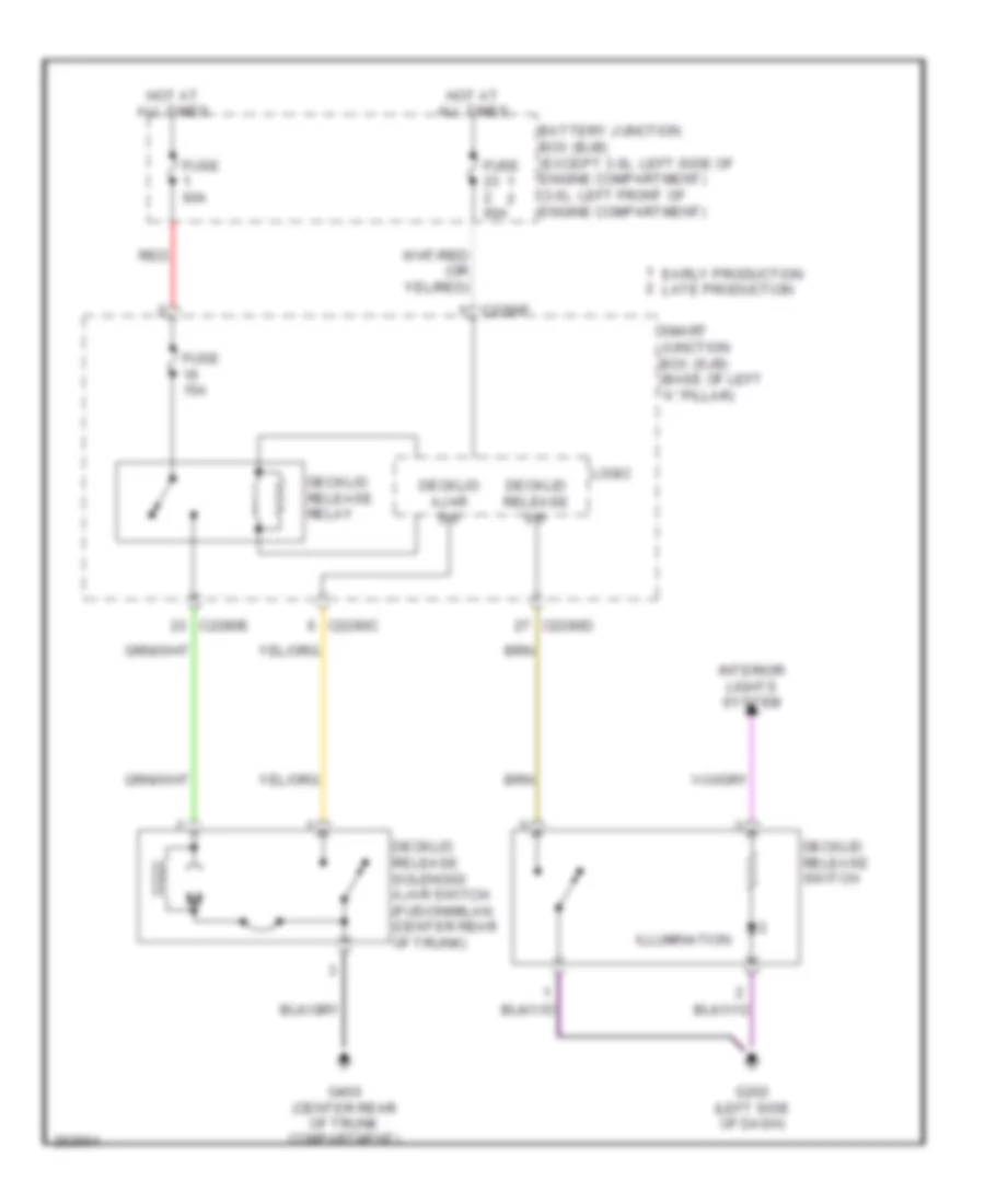 https://portal-diagnostov.com/license.html
Automotive Electricians Portal FZCO
Automotive Electricians Portal FZCO
https://portal-diagnostov.com/license.html
https://portal-diagnostov.com/license.html
Automotive Electricians Portal FZCO
Automotive Electricians Portal FZCOList of elements for Trunk Release Wiring Diagram for Ford Fusion S 2007:
- Battery junction box (bjb) (except 3.0l: left side of engine compartment) (3.0l: left front of engine compartment)
- C2280c
- C2280d
- C2280e
- C2280f
- Decklid ajar sw
- Decklid release relay
- Decklid release solenoid/ ajar switch (fusion/milan: (center rear of trunk)
- Decklid release sw
- Decklid release switch
- Early production late production
- Fuse 15a
- Fuse 60a
- G202 (left side of dash)
- G400 (center rear of trunk compartment)
- Hot at all times
- Illumination
- Interior lights system
- Logic
- Red
- Smart junction box (sjb) (base of left "a" pillar)
WARNING SYSTEMS
Warning Systems Wiring Diagram for Ford Fusion S 2007
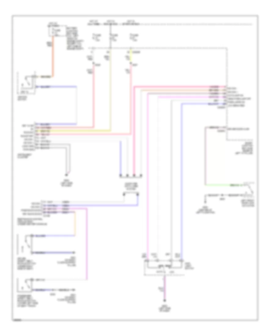 https://portal-diagnostov.com/license.html
Automotive Electricians Portal FZCO
Automotive Electricians Portal FZCO
https://portal-diagnostov.com/license.html
https://portal-diagnostov.com/license.html
Automotive Electricians Portal FZCO
Automotive Electricians Portal FZCOList of elements for Warning Systems Wiring Diagram for Ford Fusion S 2007:
- Auto
- Autolamp on
- Battery junction box (bjb) (3.0l: left front of engine compt) (except 3.0l: left side of engine compt)
- C2280b
- C2280c
- C2280d
- C310b
- Computer data lines system
- Cr201
- Cr203
- Driver door ajar
- Driver safety belt buckle switch (under right side of seat)
- Drv buckle sw
- Fuse 15a
- Fuse 7.5a
- G202 (left side of dash)
- G300 (center of left floor pan)
- G301 (on right floor support pillar)
- Head parklamp off
- Hot at all times
- Hot in run or acc
- Hot in start or run
- Hs can +
- Hs can -
- Ignition switch
- Instrument cluster
- Key in
- Key in ign
- Left front door lock actuator
- Logic gnd
- Low
- Low beam req
- Main light switch
- Ms can +
- Ms can -
- Off
- Park
- Parklamps on
- Pass buckle sw
- Passenger safety belt buckle switch (lower left side of seat track)
- Pwr gnd
- Restraints control module (rcm) (under center console)
- Run/acc
- Run/start
- S227
- S229
- S300
- S500
- Smart junction box (sjb) (base of left "a" pillar)
- Vdb04
- Vdb05
WIPER/WASHER
Wiper/Washer Wiring Diagram for Ford Fusion S 2007
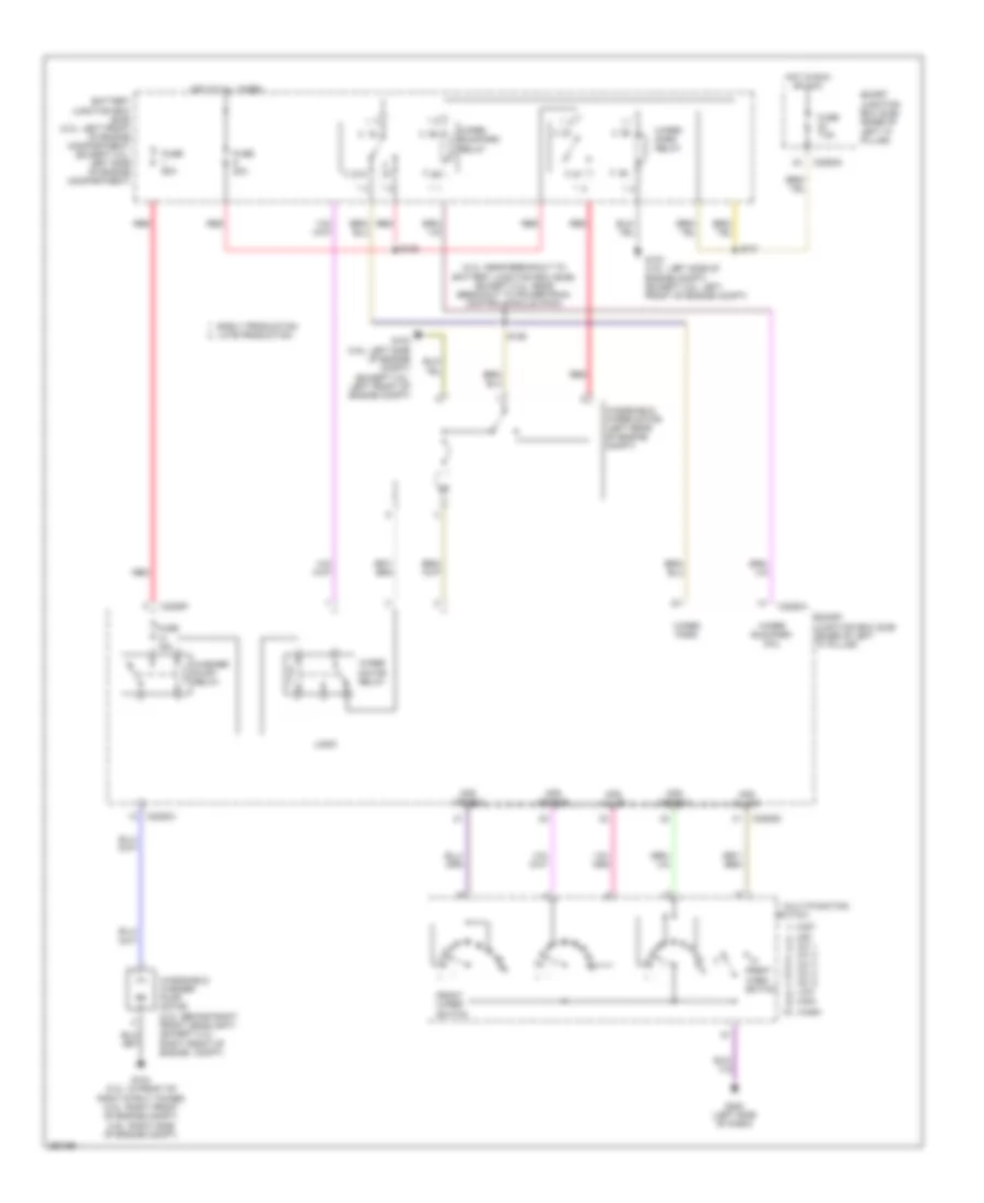 https://portal-diagnostov.com/license.html
Automotive Electricians Portal FZCO
Automotive Electricians Portal FZCO
https://portal-diagnostov.com/license.html
https://portal-diagnostov.com/license.html
Automotive Electricians Portal FZCO
Automotive Electricians Portal FZCOList of elements for Wiper/Washer Wiring Diagram for Ford Fusion S 2007:
- (2.3l: near breakout to battery junction box (bjb)) (except 2.3l: near breakout to powertrain control module (pcm))
- 87a
- Battery junction box (bjb) (3.0l: left front of engine compartment) (except 3.0l: left side of engine compartment)
- C2280a
- C2280d
- C2280f
- Early production late production
- Front wash switch
- Front wiper switch
- Fuse 15a
- Fuse 20a
- Fuse 60a
- Fuse 7.5a
- G103 (3.5l: left side of engine compt) (except 3.5l: left front of engine compt)
- G104 (2.3l: in front of right strut tower) (3.0l: right front of engine compt) (3.5l: right side of engine compt)
- G202 (left side of dash)
- Hot at all times
- Hot in run or acc
- Logic
- Mfs code a
- Mfs code b
- Mfs code c
- Mfs h line
- Mfs w line
- Mist 1)
- Multi-function
- Off 2) int 1 3) int 2 4) int 3 5) int 4 6) int 5 7) low 8) high 9) 10) wash
- Red
- S126
- S128
- S131
- Smart junction box (sjb) (base of left "a" pillar)
- Switch
- Washer pump relay
- Windshield washer pump motor (2.3l: behind right front headlight) (except 2.3l: right front of engine compt)
- Windshield wiper motor (left rear of engine compt)
- Wiper motor relay
- Wiper park
- Wiper park relay
- Wiper run/park coil
- Wiper run/park relay

 Čeština
 Dansk
Dansk Deutsch
 Ελληνικά
 English
 English
 Español
 Suomi
Suomi Français
 Français
 עברית
עברית Hrvatski
 Magyar
 Italiano
 한국어
한국어 Nederlands
 Polski
 Português
 Português
 Română
 Русский
 Slovenčina
 Slovenščina
 Svenska
 Türkçe
 中文 (中国)
