AIR CONDITIONING
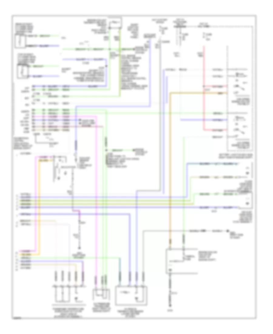
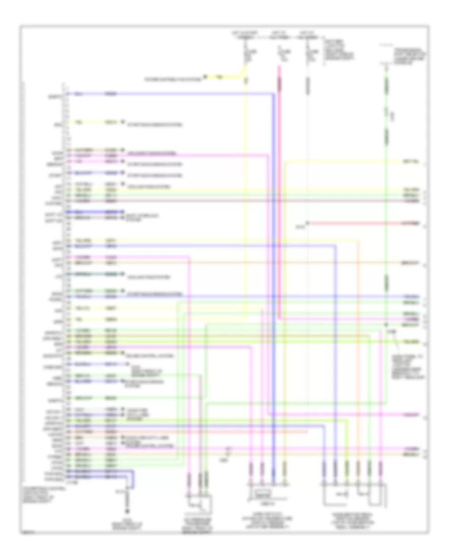
Automatic A/C Wiring Diagram (1 of 2) for Ford Mustang GT 2013
 https://portal-diagnostov.com/license.html
Automotive Electricians Portal FZCO
Automotive Electricians Portal FZCO
https://portal-diagnostov.com/license.html
https://portal-diagnostov.com/license.html
Automotive Electricians Portal FZCO
Automotive Electricians Portal FZCO
List of elements for Automatic A/C Wiring Diagram (1 of 2) for Ford Mustang GT 2013:
- (blower motor assembly) blower motor speed control
- (front of a/c compressor)
- (main wiring harness, in breakout to front display interface module)
- (near breakout to driver temperature blend door actuator)
- (near breakout to floor mode door actuator)
- (right kick panel)
- (right side of dash) g200
- (right side of engine compt)
- A/c clutch relay
- A/c compressor clutch field coil
- Ambient air temperature sensor (center front of engine compt)
- Battery junction box (bjb)
- Blower motor (under hvac unit)
- Blower motor relay
- Blower relay
- C110
- C211
- C212
- C2280a
- C2280e
- C294a
- C294b
- Ch122
- Ch123
- Ch202
- Ch203
- Ch207
- Ch208
- Ch212
- Ch213
- Ch228
- Ch229
- Ch238
- Ch239
- Chs29
- Chs30
- Computer data lines system
- Defogger system
- Defrost request
- Driv htd seat req
- Driv temp act fdbk
- Driv temp door ccw
- Driv temp door cw
- Driver sunload
- Driver temperature blend door actuator (left side of evaporator assembly)
- Evap temp sensor
- Evaporator discharge air temperature sensor (right side of evaporator assembly)
- Fuse 10a
- Fuse 30a
- Fuse 5a
- G100
- G201 (right side of dash)
- Gd116
- Gnd
- Hot at all times
- Hot in run or acc
- Hvac module
- In car temp sensor
- Lh111
- Mode 1 act fdbk
- Mode door 1 ccw
- Mode door 1 cw
- Mode door 2 ccw
- Mode door 2 cw
- Ms can+
- Ms can-
- Mtr
- Oat
- Panel/defrost mode door actuator (right side of dash)
- Pass htd seat req
- Pass temp act fdbk
- Pass temp door ccw
- Pass temp door cw
- Passenger sunload
- Pwm
- Recirc ccw
- Recirc cw
- Red
- Return
- Rh111
- S112
- S130
- S201
- S202
- S203 (main wiring harness, near breakout to panel/defrost mode door actuator)
- S218
- Sbp15
- Seats system
- Smart junction box (sjb)
- Variable blwr ctrl
- Vbatt
- Vdb06
- Vdb07
- Vh101
- Vh406
- Vh407
- Vh414
- Vh416
- Vh417
- Vh436
- Vh440
- Vh441
- Vref
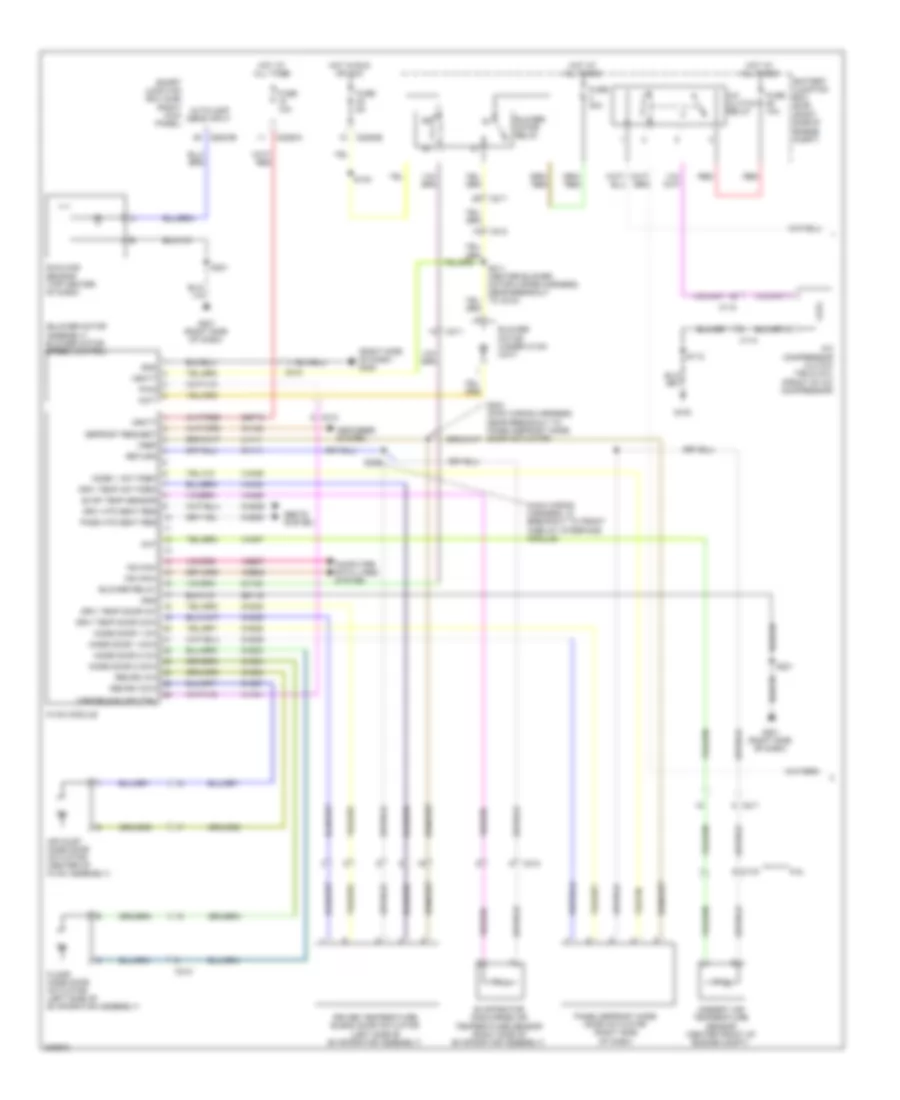
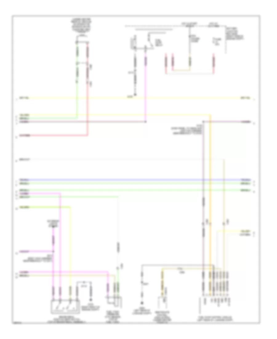
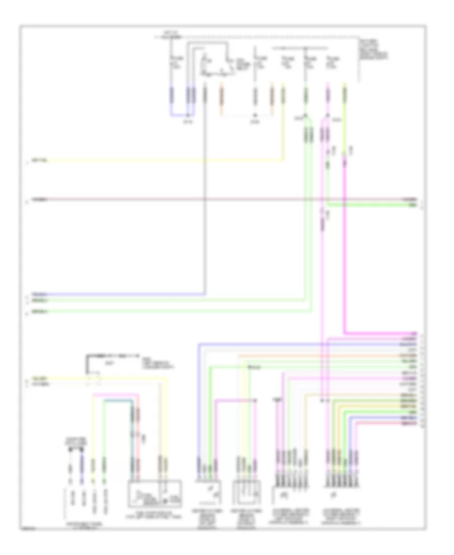
Automatic A/C Wiring Diagram (2 of 2) for Ford Mustang GT 2013
 https://portal-diagnostov.com/license.html
Automotive Electricians Portal FZCO
Automotive Electricians Portal FZCO
https://portal-diagnostov.com/license.html
https://portal-diagnostov.com/license.html
Automotive Electricians Portal FZCO
Automotive Electricians Portal FZCOList of elements for Automatic A/C Wiring Diagram (2 of 2) for Ford Mustang GT 2013:
- (5.8l: engine control sensor & fuel charge wiring harness, near breakout to ignition transformer capacitor 1) (5.0l: engine control sensor & fuel charge wiring harness, near breakout to c1019)
- (rear of right cylinder head) cylinder head temperature sensor
- (right kick panel)
- (top of right cylinder head) cylinder head temperature sensor
- 3.7l
- 5.8l
- A/c pressure transducer (right front of engine compt)
- Accr
- Acpt
- Air inlet mode door actuator (center of hvac assembly)
- Autolamp sensor in
- Battery junction box (bjb) (right side of engine compt)
- C1026
- C1381b
- C1381e
- C175b
- C175e
- C212
- C2280b
- Cec01
- Cec02
- Ch302
- Cht
- Computer data lines system
- Ect
- Engine controls system
- Engine coolant temperature (ect) sensor (5.8l) (right front of engine)
- Engine cooling fan motor (front of engine compt)
- Except 3.7l
- Except 5.8l
- Floor mode door actuator (left side of evaporator assembly)
- Fuse 40a
- Fuse 5a
- G100
- G200 (right side of dash)
- G201 (right side of dash)
- Hfc
- High speed engine cooling fan relay
- Hot at all times
- Hot in start or run
- Hot w/ pcm power relay energized
- Hs can+
- Hs can-
- In-vehicle temperature sensor (lower center of dash)
- Le423
- Lfc
- Low speed engine cooling fan relay
- Nca
- Passenger temperature blend door actuator (right side of evaporator assembly)
- Powertrain control module (pcm) (right front of engine compt)
- Re141
- Re405
- S102 (except 3.7l)
- S106 (except 3.7l) (engine control sensor & fuel charge wiring harness, near breakout to egr system module)
- S112
- S121
- S125
- S200
- S201
- Sigrtn
- Smart junction box (sjb)
- Solid state
- Sunload sensor (top center of dash)
- Thermal fuse
- Vdb04
- Vdb05
- Ve712
- Vh433
- Vref
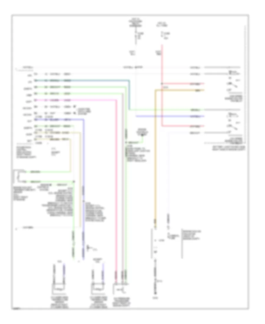
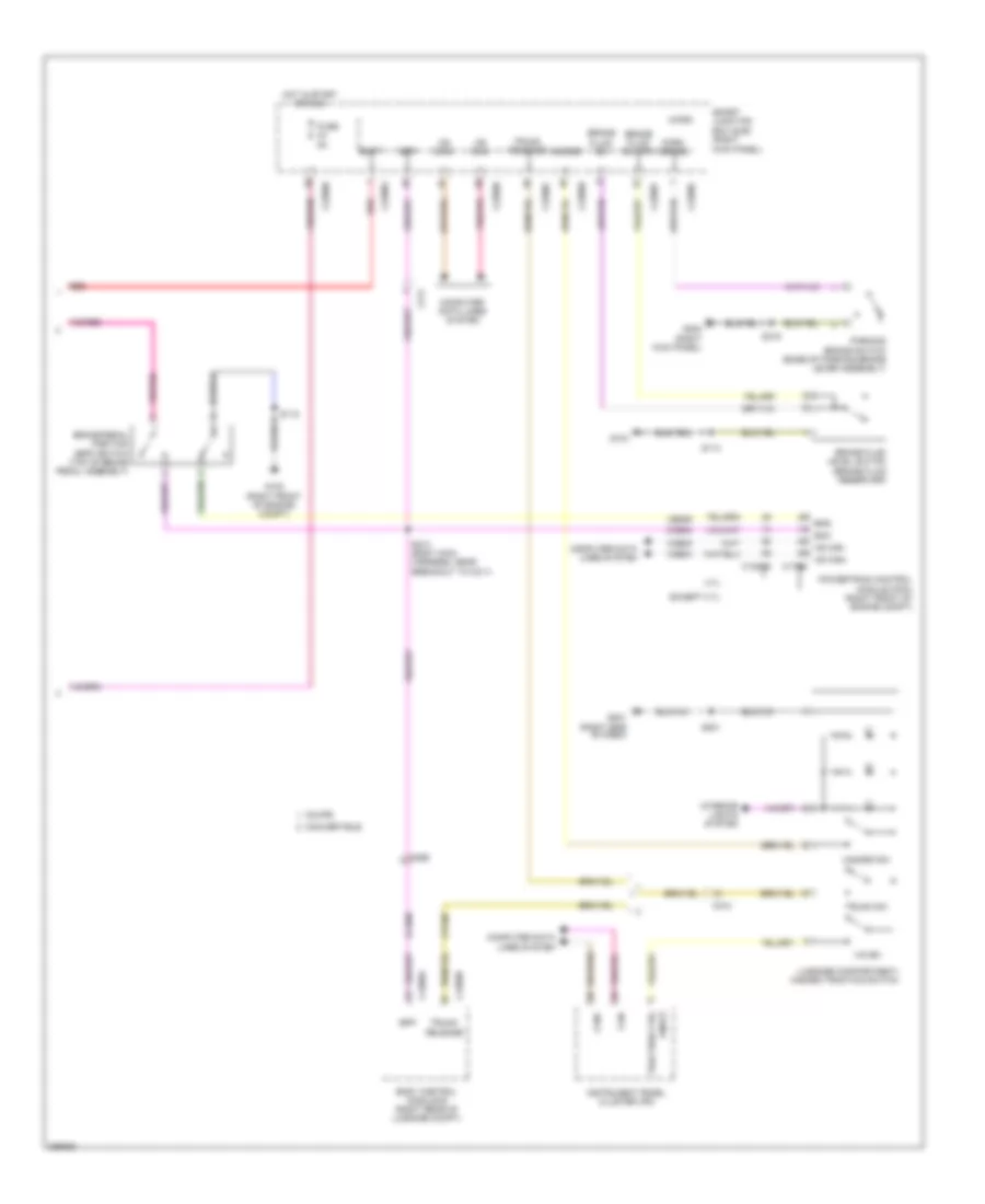
Manual A/C Wiring Diagram (1 of 2) for Ford Mustang GT 2013
 https://portal-diagnostov.com/license.html
Automotive Electricians Portal FZCO
Automotive Electricians Portal FZCO
https://portal-diagnostov.com/license.html
https://portal-diagnostov.com/license.html
Automotive Electricians Portal FZCO
Automotive Electricians Portal FZCOList of elements for Manual A/C Wiring Diagram (1 of 2) for Ford Mustang GT 2013:
- (blower motor assembly) blower motor speed control
- (front of a/c compressor)
- (main wiring harness, in breakout to front display interface module)
- (right kick panel)
- (right side of dash) g200
- (right side of engine compt)
- 5.8l
- A/c clutch relay
- A/c compressor clutch field coil
- Air inlet mode door actuator (center of hvac assembly)
- Ambient air temperature sensor (center front of engine compt)
- Autolamp sens input
- Battery junction box (bjb)
- Blower motor (under hvac unit)
- Blower motor relay
- Blower relay
- C110
- C133
- C211
- C212
- C2280a
- C2280b
- C2280e
- Ch122
- Ch123
- Ch202
- Ch203
- Ch207
- Ch208
- Ch228
- Ch229
- Ch238
- Ch239
- Chs29
- Chs30
- Computer data lines system
- Defogger system
- Defrost request
- Driv htd seat req
- Driv temp act fdbk
- Driv temp door ccw
- Driv temp door cw
- Driver temperature blend door actuator (left side of evaporator assembly)
- Evap temp sensor
- Evaporator discharge air temperature sensor (right side of evaporator assembly)
- Floor mode door actuator (left side of evaporator assembly)
- Fuse 10a
- Fuse 30a
- Fuse 5a
- G100
- G201 (right side of dash)
- Gd116
- Gnd
- Hot at all times
- Hot in run or acc
- Hvac module
- Lh111
- Mode 1 act fdbk
- Mode door 1 ccw
- Mode door 1 cw
- Mode door 2 ccw
- Mode door 2 cw
- Mot-
- Ms can+
- Ms can-
- Oat
- Panel/defrost mode door actuator (right side of dash)
- Pass htd seat req
- Pwm
- Recirc ccw
- Recirc cw
- Red
- Return
- Rh111
- S112
- S130
- S201
- S202
- S203 (main wiring harness, near breakout to panel/defrost mode door actuator)
- S211 (heater blower motor wiring harness, near breakout to c212)
- Sbp15
- Seats system
- Smart junction box (sjb)
- Sunload sensor (top center of dash)
- Variable blwr ctrl
- Vbatt
- Vdb06
- Vdb07
- Vh101
- Vh406
- Vh407
- Vh436
- Vh440
- Vref
Manual A/C Wiring Diagram (2 of 2) for Ford Mustang GT 2013
 https://portal-diagnostov.com/license.html
Automotive Electricians Portal FZCO
Automotive Electricians Portal FZCO
https://portal-diagnostov.com/license.html
https://portal-diagnostov.com/license.html
Automotive Electricians Portal FZCO
Automotive Electricians Portal FZCOList of elements for Manual A/C Wiring Diagram (2 of 2) for Ford Mustang GT 2013:
- 3.7l
- 5.8l
- A/c pressure transducer (right front of engine compt)
- Accr
- Acpt
- Battery junction box (bjb) (right side of engine compt)
- C1026
- C1381b
- C1381e
- C175b
- C175e
- Cec01
- Cec02
- Ch302
- Cht
- Computer data lines system
- Cylinder head temperature sensor (rear of right cylinder head)
- Cylinder head temperature sensor (top of right cylinder head)
- Ect
- Engine controls system
- Engine coolant temperature (ect) sensor (5.8l) (right front of engine)
- Engine cooling fan motor (front of engine compt)
- Except 3.7l
- Except 5.8l
- Fuse 40a
- Fuse 5a
- G100
- Hfc
- High speed engine cooling fan relay
- Hot at all times
- Hot w/ pcm power relay energized
- Hs can+
- Hs can-
- Le423
- Lfc
- Low speed engine cooling fan relay
- Nca
- Powertrain control module (pcm) (right front of engine compt)
- Re141
- Re405
- S102 (except 3.7l) (5.8l: engine control sensor & fuel charge wiring harness, near breakout to ignition transformer capacitor 1) (5.0l: engine control sensor & fuel charge wiring harness, near breakout to c1019)
- S106 (except 3.7l) (engine control sensor & fuel charge wiring harness, near breakout to egr system module)
- S112
- S121
- S125
- S199 (dash panel to headlamp junction wiring harness, near breakout to right headlamp)
- Sigrtn
- Thermal fuse
- Vdb04
- Vdb05
- Ve712
- Vh433
- Vref
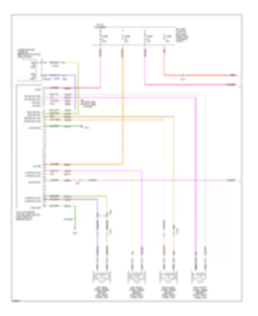
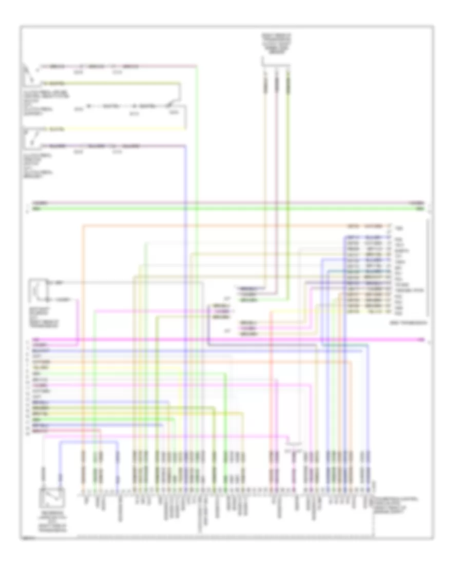
ANTI-LOCK BRAKES
Anti-lock Brakes Wiring Diagram (1 of 2) for Ford Mustang GT 2013
 https://portal-diagnostov.com/license.html
Automotive Electricians Portal FZCO
Automotive Electricians Portal FZCO
https://portal-diagnostov.com/license.html
https://portal-diagnostov.com/license.html
Automotive Electricians Portal FZCO
Automotive Electricians Portal FZCOList of elements for Anti-lock Brakes Wiring Diagram (1 of 2) for Ford Mustang GT 2013:
- (under center console) restraints control module (rcm)
- Anti-lock brake system (abs) module (left front of engine compt)
- Battery junction box (bjb) (right side of engine compt)
- C2041b
- C211
- C219
- C264
- C431
- Cbp34
- Computer data lines system
- Fuse 10a
- Fuse 30a
- Fuse 40a
- Fuse 80a
- G101
- Gd120
- Hot at all times
- Hs can+
- Hs can-
- Left front wheel speed sensor (left front wheel hub)
- Left rear wheel speed sensor (left rear wheel hub)
- Lf spd sn high
- Lf spd sn low
- Logic gnd
- Lr spd sn high
- Lr spd sn low
- Motor gnd
- Nca
- Pump
- Rca17
- Rca18
- Rca19
- Rca20
- Rcs hs can+
- Rcs hs can-
- Red
- Rf spd sn high
- Rf spd sn low
- Right front wheel speed sensor (right front wheel hub)
- Right rear wheel speed sensor (right rear wheel hub)
- Rr spd sn high
- Rr spd sn low
- Run/start
- S114
- Sbb08
- Sbb10
- Valves
- Vca03
- Vca04
- Vca05
- Vca06
- Vca23
- Vca24
- Vdb04
- Vdb05
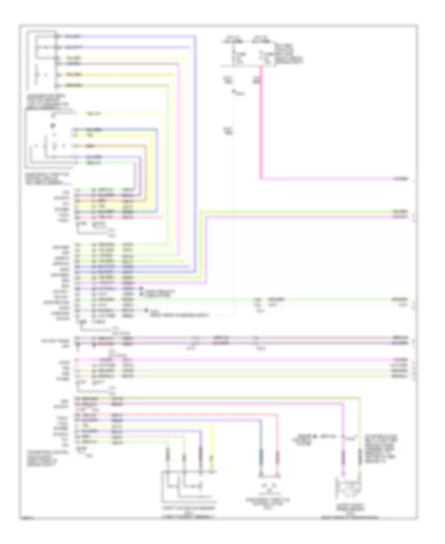
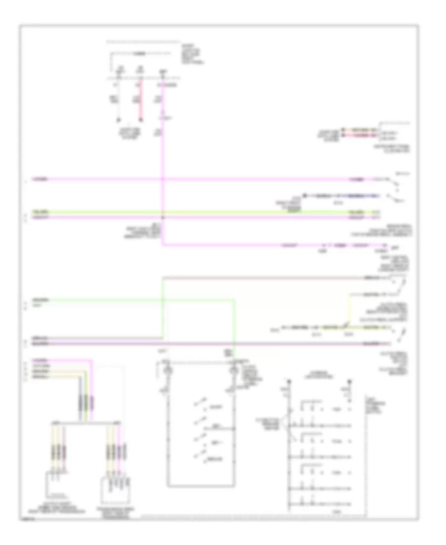
Anti-lock Brakes Wiring Diagram (2 of 2) for Ford Mustang GT 2013
 https://portal-diagnostov.com/license.html
Automotive Electricians Portal FZCO
Automotive Electricians Portal FZCO
https://portal-diagnostov.com/license.html
https://portal-diagnostov.com/license.html
Automotive Electricians Portal FZCO
Automotive Electricians Portal FZCOList of elements for Anti-lock Brakes Wiring Diagram (2 of 2) for Ford Mustang GT 2013:
- 3.7l
- Batt
- Body control module b (right rear of luggage compt)
- Bpp
- Bps boo hs can- hs can+ c175b
- Brake fluid level switch (brake fluid reservoir)
- Brake fluid sw
- Brake fluid sw rtn
- Brake pedal position (bpp) switch (top of brake pedal assembly)
- C1381b
- C210
- C211
- C2280b
- C2280c
- C2280f
- C2280g
- C265
- C4368a
- C4368b
- Can+
- Can-
- Ccb08
- Ce509
- Computer data lines system
- Convertible
- Coupe
- Cpl60
- Except 3.7l
- Fuse 5a
- G102 (right front of engine compt)
- G104
- G201 (right side of dash)
- G203 (right kick panel)
- Hazard
- Hazard sw
- Hot in start or run
- Instrument panel cluster (ipc)
- Interior lights system
- Ivd sw
- Luggage compartment/ hazard traction switch
- Micro
- Ms can+
- Ms can-
- On/off
- Park brake
- Parking brake switch (base of parking brake lever assembly)
- Powertrain control module (pcm) (right front of engine compt)
- Red
- S113
- S115
- S201
- S213 (body main harness, near breakout to c211)
- S319
- Smart junction box (sjb) (right kick panel)
- Traction ctrl
- Trunk release
- Trunk sw
- Vdb04
- Vdb05
ANTI-THEFT
Forced Entry Wiring Diagram (1 of 2) for Ford Mustang GT 2013
 https://portal-diagnostov.com/license.html
Automotive Electricians Portal FZCO
Automotive Electricians Portal FZCO
https://portal-diagnostov.com/license.html
https://portal-diagnostov.com/license.html
Automotive Electricians Portal FZCO
Automotive Electricians Portal FZCOList of elements for Forced Entry Wiring Diagram (1 of 2) for Ford Mustang GT 2013:
- (body main wiring harness, near breakout to c260)
- (body main wiring harness, near breakout to c919)
- (body main wiring harness, near breakout to c919) s327
- (not used)
- (right front door window regulator wiring harness, near breakout to right front power window motor) s600
- Accessory delay relay
- All lock/ unlock relay
- Anti-theft
- Auto
- B10
- C10
- C213
- C214
- C2280b
- C2280c
- C2280d
- C2280f
- Computer data lines system
- Control
- Door lock
- Door reset sw
- Door unlock
- Dr ajar
- Driver door unlock relay
- Driver side door lock switch
- Fuse 10a
- Fuse 15a
- Fuse 20a
- G203 (right kick panel)
- G204 (left kick panel)
- Headlights system
- Horns system
- Hot at all times
- Hrn rly
- Internal tpms/rke antenna
- Left front power window motor (driver's door)
- Lf door ajar
- Lf door key lock
- Lock
- Micro
- Ms can +
- Ms can -
- Passenger side door lock switch
- Power distribution system
- Rf door ajar
- Rke receiver
- S215
- S248
- S326
- S500 (left front door window regulator wiring harness, near breakout to left front power window motor)
- S503
- S602
- Smart junction box (sjb) (right kick panel)
- Trunk rel (fet)
- Unlock
Forced Entry Wiring Diagram (2 of 2) for Ford Mustang GT 2013
 https://portal-diagnostov.com/license.html
Automotive Electricians Portal FZCO
Automotive Electricians Portal FZCO
https://portal-diagnostov.com/license.html
https://portal-diagnostov.com/license.html
Automotive Electricians Portal FZCO
Automotive Electricians Portal FZCOList of elements for Forced Entry Wiring Diagram (2 of 2) for Ford Mustang GT 2013:
- Body control module b (right rear of luggage compt)
- C11
- C213 c8
- C214 c7
- C4368a
- C7 c213
- C8 c214
- C913
- Close
- Convertible
- Coupe
- Dr ajar
- Driver door latch (driver's door)
- G100
- G203 (right kick panel)
- G204 (left kick panel)
- Hood switch (right front of engine compt)
- Intrusions sense
- Ism ground
- Ism power
- Lin
- Open
- Overhead console
- Passenger door latch (front passenger's door)
- Reset
- Right front power window motor (front passenger's door)
- S112
- S233 (body main wiring harness, near breakout to c260)
- S328
- S503
- S602
- Set
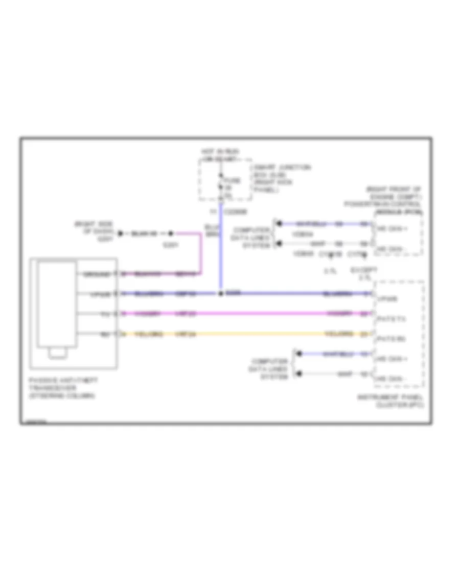
Passive Anti-theft Wiring Diagram for Ford Mustang GT 2013
 https://portal-diagnostov.com/license.html
Automotive Electricians Portal FZCO
Automotive Electricians Portal FZCO
https://portal-diagnostov.com/license.html
https://portal-diagnostov.com/license.html
Automotive Electricians Portal FZCO
Automotive Electricians Portal FZCOList of elements for Passive Anti-theft Wiring Diagram for Ford Mustang GT 2013:
- (right front of engine compt) powertrain control module (pcm)
- (right side of dash) g201
- 3.7l
- C1381b
- C175b
- C2280b
- Cbp36
- Computer data lines system
- Except 3.7l
- Fuse 5a
- Gd116
- Ground
- Hot in run or start
- Hs can +
- Hs can -
- Instrument panel cluster (ipc)
- Passive anti-theft transceiver (steering column)
- Pats rx
- Pats tx
- S201
- S236
- Smart junction box (sjb) (right kick panel)
- Vdb04
- Vdb05
- Vpwr
- Vrt23
- Vrt24
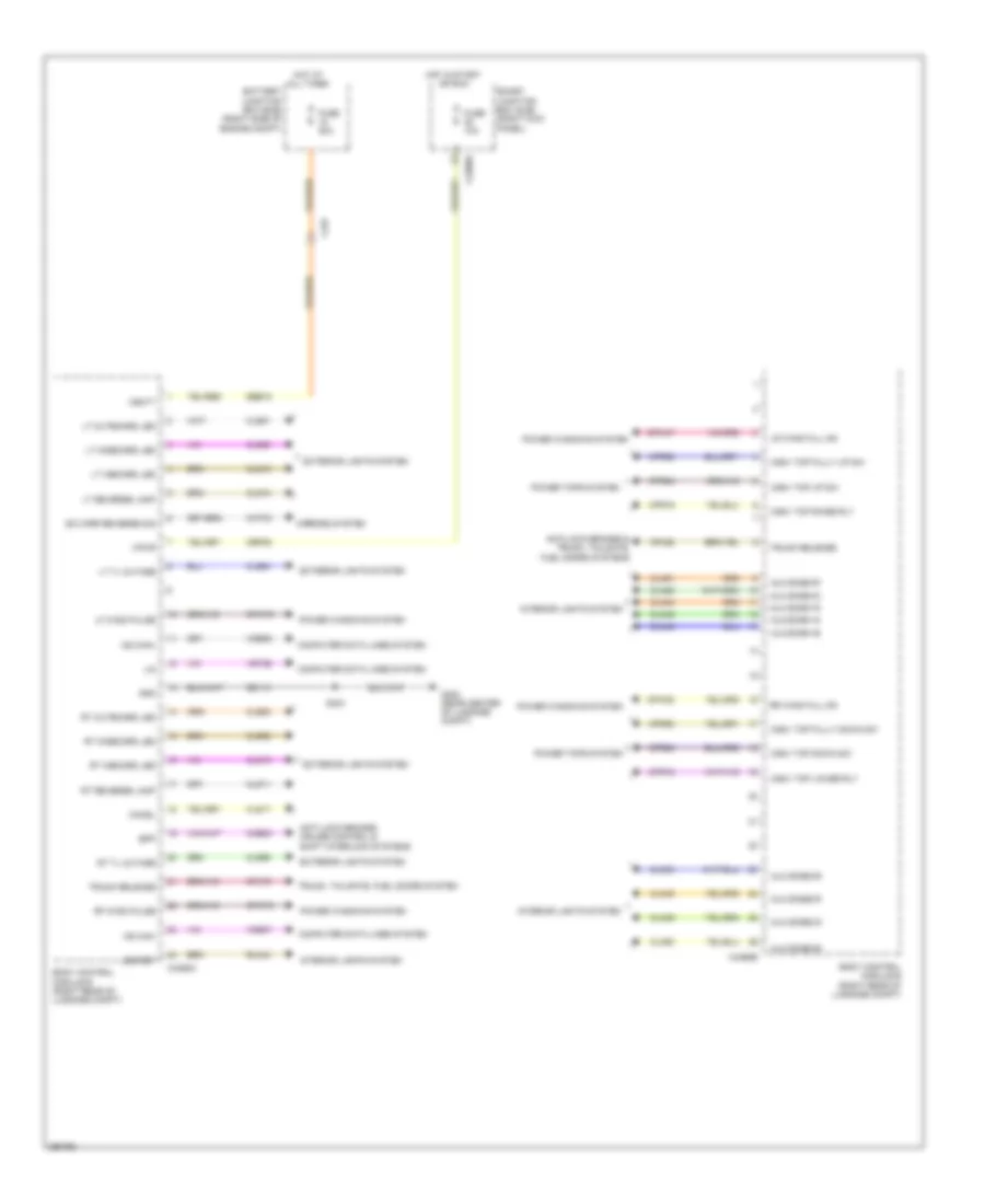
BODY CONTROL MODULES
Body Control Module Wiring Diagram for Ford Mustang GT 2013
 https://portal-diagnostov.com/license.html
Automotive Electricians Portal FZCO
Automotive Electricians Portal FZCO
https://portal-diagnostov.com/license.html
https://portal-diagnostov.com/license.html
Automotive Electricians Portal FZCO
Automotive Electricians Portal FZCOList of elements for Body Control Module Wiring Diagram for Ford Mustang GT 2013:
- Alm zone1-b
- Alm zone1-g
- Alm zone1-r
- Alm zone2-b
- Alm zone2-g
- Alm zone2-r
- Alm zone3-b
- Alm zone3-g
- Alm zone3-r
- Anti-lock brakes & trunk, tailgate, fuel doors systems
- Anti-lock brakes, cruise control & shift interlock systems
- Battery junction box (bjb) (right side of engine compt)
- Body control module b (right rear of luggage compt)
- Bpp
- C2280d
- C237
- C4368a
- C4368b
- Cat03
- Cbp35
- Ccb08
- Chmsl
- Cln44
- Cln45
- Cln46
- Cln48
- Cln49
- Cln50
- Cln51
- Cln52
- Cln53
- Cls10
- Cls11
- Cls17
- Cls18
- Cls19
- Cls50
- Cls51
- Cls52
- Cls53
- Cls54
- Cls55
- Computer data lines system
- Conv top down sw
- Conv top fully down sw
- Conv top fully up sw
- Conv top lower rly
- Conv top raise rly
- Conv top up sw
- Cpl60
- Cpl79
- Cpr18
- Cpr19
- Cpr23
- Cpr24
- Cpr92
- Cpr93
- Cpw47
- Cpw53
- Cpw73
- E/c mirr reverse sig
- Exterior lights system
- Fuse 10a
- Fuse 20a
- G402 (rear center of luggage compt)
- Gd110
- Gnd
- Hot at all times
- Hot in start or run
- Interior lights system
- Led ret
- Lf wind pulse
- Lin
- Lr wind full dn
- Lt inboard led
- Lt midboard led
- Lt outboard led
- Lt reverse lamp
- Lt tl outage
- Mirrors system
- Ms can+
- Ms can-
- Power tops system
- Power windows system
- Rf wind pulse
- Rln44
- Rr wind full dn
- Rt inboard led
- Rt midboard led
- Rt outboard led
- Rt reverse lamp
- Rt tl outage
- S404
- Sbb18
- Smart junction box (sjb) (right kick panel)
- Trunk release
- Trunk, tailgate, fuel doors system
- Vbatt
- Vdb06
- Vdb07
- Vpwr
- Vrt26
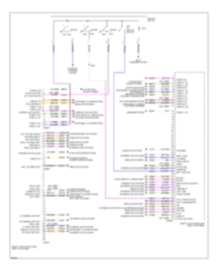
Smart Junction Box Wiring Diagram (1 of 2) for Ford Mustang GT 2013
 https://portal-diagnostov.com/license.html
Automotive Electricians Portal FZCO
Automotive Electricians Portal FZCO
https://portal-diagnostov.com/license.html
https://portal-diagnostov.com/license.html
Automotive Electricians Portal FZCO
Automotive Electricians Portal FZCOList of elements for Smart Junction Box Wiring Diagram (1 of 2) for Ford Mustang GT 2013:
- (not used)
- Acc
- Air conditioning & wiper/washer systems
- Air conditioning system
- Anti-lock brakes system
- Anti-theft
- Auto
- Auto lamp sensor in
- Backlighting led (fet)
- Bpp
- Brake fluid sw
- Brake fluid sw rtn
- C2280a
- C2280b
- C2280e
- C2280f
- Cbp28
- Cbp29
- Cbp30
- Cbp31
- Cbp33
- Cbp34
- Cbp36
- Cbp37
- Cbp45
- Ccb08
- Cdc30
- Cdc33
- Cdc54
- Ce612
- Clf04
- Clf05
- Clf06
- Clf07
- Clf08
- Clf12
- Clf17
- Clf18
- Clf19
- Clf21
- Clf23
- Clf27
- Cln28
- Cls21
- Cls25
- Cls30
- Cls32
- Cls34
- Cls39
- Cls41
- Cmc19
- Computer data lines system
- Cpl25
- Crh02
- Crw01
- Defogger system
- Dim sw gnd
- Dimmer sw
- Dome lp
- Door locks & anti-theft systems
- Exterior lights & anti-lock brakes systems
- Exterior lights system
- Flash-to-pass
- Floor lamp (fet)
- Fog lamp
- Fog lamp relay
- Fues 14, 10a
- Fues 29, 5a
- Fuse 15, 10a
- Fuse 16, 15a
- Fuse 20, 15a
- Fuse 26, 10a
- Fuse 27, 20a
- Fuse 28, 5a
- Fuse 30, 5a
- Fuse 31, 10a
- Fuse 33, 10a
- Fuse 34, 5a
- Fuse 35, 10a
- Fuse 36, 5a
- Fuse 37, 10a
- Fuse 39, 20a
- Fuse 40, 20a
- Fuse 41, 15a
- Fuse 43, 10a
- Fuse 45, 5a
- Fuse 46, 7.5a
- Hazard
- Headlights system
- High beam
- High beam relay
- Horn relay
- Horns system
- Hot in run or acc
- Hot in start or run
- Ignition switch
- Instrument cluster & anti-theft systems
- Instrument cluster system
- Interior lighting (fet)
- Interior lights system
- Key in ignition
- Key in ignition switch
- Left low beam (fet)
- Left turn
- Lf turn lamp (fet)
- Lh corner lamp (fet)
- Lock
- Low beam
- Micro
- Ms can +
- Ms can -
- Navigation & sound systems
- Navigation system
- Off
- Park lamp on
- Park lamp relay
- Power distribution system
- Rf turn lamp (fet)
- Rh corner lamp (fet)
- Right low ream (fet)
- Right turn
- Rln29
- Rmc19
- Run
- S240
- Sbp14
- Sbp15
- Sbp16
- Sbp20
- Sbp26
- Sbp27
- Sbp39
- Shift interlock system
- Smart junction box (sjb) (right kick panel)
- Srh01
- Start
- Starter mtr ctrl sns
- Starting/ charging system
- Starting/charging system
- Tpms 1 (fet)
- Tpms 2 (fet)
- Tpms 3 (fet)
- Vdb06
- Vdb07
- Vlf14
- Vln04
- Vln18
- Vln33
- White light (fet)
- Wiper status
- Wiper/washer & headlights systems
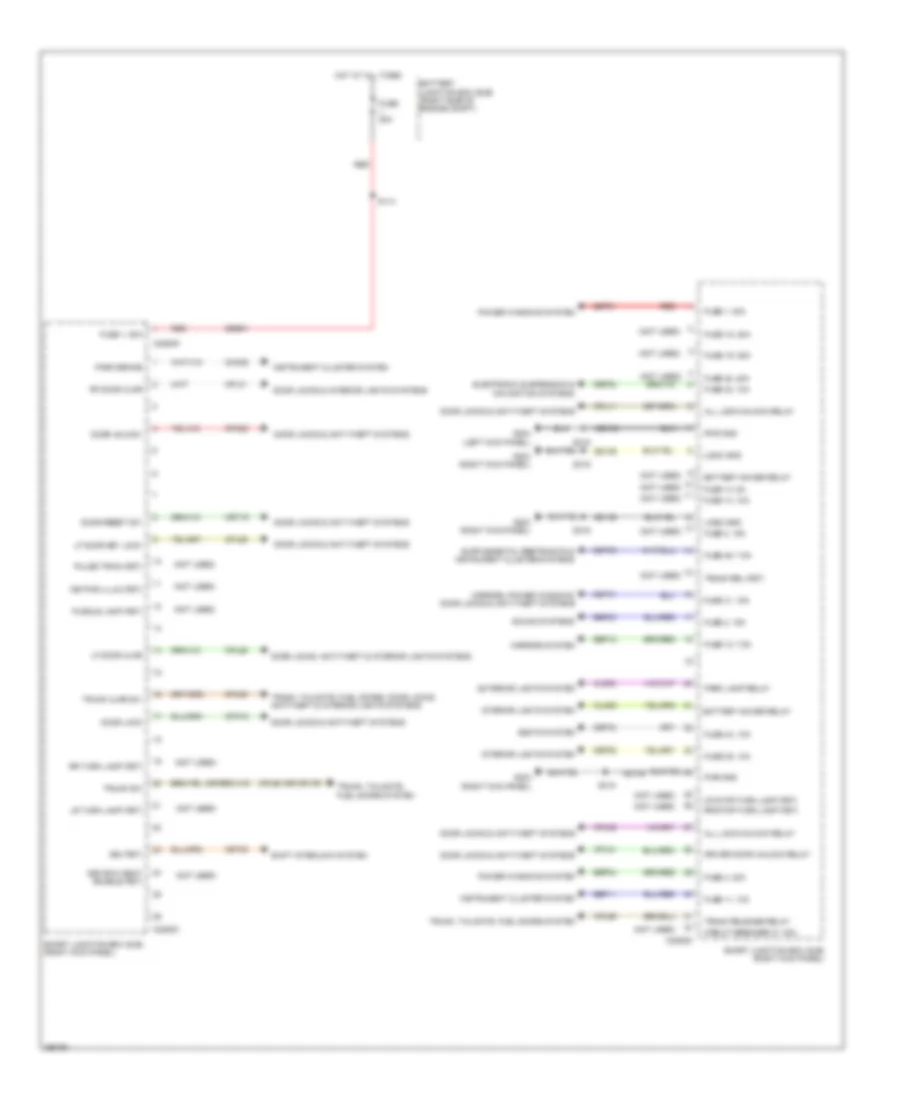
Smart Junction Box Wiring Diagram (2 of 2) for Ford Mustang GT 2013
 https://portal-diagnostov.com/license.html
Automotive Electricians Portal FZCO
Automotive Electricians Portal FZCO
https://portal-diagnostov.com/license.html
https://portal-diagnostov.com/license.html
Automotive Electricians Portal FZCO
Automotive Electricians Portal FZCOList of elements for Smart Junction Box Wiring Diagram (2 of 2) for Ford Mustang GT 2013:
- (not used)
- (or cpl79)
- 3rd row seat enable (fet)
- All lock/unlock relay
- Battery junction box (bjb) (right side of engine compt)
- Battery saver relay
- Bsi (fet)
- C2280c
- C2280d
- C2280g
- Cbp32
- Cbp35
- Cbp41
- Cbp43
- Cbp46
- Cet53
- Circuit breaker 47, 30a
- Cln09
- Cls30
- Cmc25
- Cpk19
- Cpk23
- Cpl11
- Cpl26
- Cpl29
- Cpl31
- Cpl51
- Cpl52
- Cpl58
- Cpl59
- Cpl60
- Crt19
- Door lock
- Door locks & anti-theft systems
- Door locks & interior lights systems
- Door locks, anti-theft & interior lights systems
- Door reset sw
- Door unlock
- Driver door unlock relay
- Electronic suspension & navigation systems
- Exterior lights system
- Fuse 1, 30a
- Fuse 1, 80a
- Fuse 11, 10a
- Fuse 12, 7.5a
- Fuse 13, 5a
- Fuse 14, 10a
- Fuse 18, 20a
- Fuse 19, 25a
- Fuse 2, 15a
- Fuse 3, 15a
- Fuse 32, 10a
- Fuse 35, 10a
- Fuse 38, 20a
- Fuse 4, 30a
- Fuse 41, 15a
- Fuse 43, 10a
- Fuse 46, 7.5a
- Fuse 80a
- G203 (right kick panel)
- G204 (left kick panel)
- Gd133
- Gd139
- Hot at all times
- Instrument cluster system
- Interior lights system
- Keypad illum (fet)
- Lf door ajar
- Lf door key lock
- Logic gnd
- Lr stop/turn lamp (fet)
- Lr turn lamp (fet)
- Mirrors system
- Mirrors, power windows, door locks & anti-theft systems
- Park brake
- Park lamp relay
- Power windows system
- Puddle lamp (fet)
- Pulse train (fet)
- Pwr gnd
- Red
- Rf door ajar
- Rr stop/turn lamp (fet)
- Rr turn lamp (fet)
- S114
- S215
- S319
- Sbb01
- Sbp01
- Sbp03
- Sbp04
- Sbp11
- Sbp12
- Seats system
- Shift interlock system
- Smart junction box (sjb) (right kick panel)
- Sound systems
- Trunk ajar sw
- Trunk rel (fet)
- Trunk release relay
- Trunk sw
- Trunk, tailgate, fuel doors system
- Trunk, tailgate, fuel doors, door locks, anti-theft & interior lights systems
COMPUTER DATA LINES
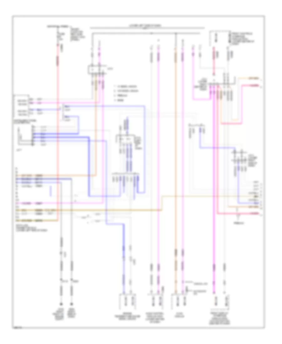
Computer Data Lines Wiring Diagram (1 of 2) for Ford Mustang GT 2013
 https://portal-diagnostov.com/license.html
Automotive Electricians Portal FZCO
Automotive Electricians Portal FZCO
https://portal-diagnostov.com/license.html
https://portal-diagnostov.com/license.html
Automotive Electricians Portal FZCO
Automotive Electricians Portal FZCOList of elements for Computer Data Lines Wiring Diagram (1 of 2) for Ford Mustang GT 2013:
- (lower center of dash)
- (lower left side of dash) j/c 1
- Audio control module (acm)
- Automatic a/c
- Base
- C211
- C2280a
- C275
- C290a
- C294a
- Cdb08
- Dash)
- Data link connector (dlc) (lower left end of dash)
- Engine temperature gauge (boss laguna)
- Front controls interface module (fcim) (lower center of dash)
- Front display interface module (fdim) (w/o navigation) (center of dash)
- Fuse 15a
- G102 (right front of engine compt)
- G200 (right side of dash)
- Gd114
- Gd119
- Hot at all times
- Hs can +
- Hs can -
- Hvac module
- Instrument panel cluster (ipc)
- J/c 3 (lower right side of dash)
- J/c 4 (lower right center of
- J/c 5
- J/c 6 (left side of dash)
- J/c 7
- Manual a/c
- Ms can +
- Ms can -
- Premium
- S115
- S200
- Sbp20
- Smart junction box (sjb) (right kick panel)
- Vdb04
- Vdb05
- Vdb06
- Vdb07
- Vdbo6
- Vdbo7
- W/ boss laguna
- W/o boss laguna
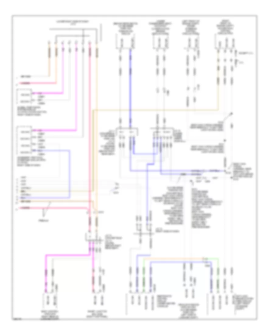
Computer Data Lines Wiring Diagram (2 of 2) for Ford Mustang GT 2013
 https://portal-diagnostov.com/license.html
Automotive Electricians Portal FZCO
Automotive Electricians Portal FZCO
https://portal-diagnostov.com/license.html
https://portal-diagnostov.com/license.html
Automotive Electricians Portal FZCO
Automotive Electricians Portal FZCOList of elements for Computer Data Lines Wiring Diagram (2 of 2) for Ford Mustang GT 2013:
- (behind rear seats) (w/ reverse park aid) parking aid module
- (body main wiring harness, near breakout to anti-lock brake system module) s133
- (convertible: body main wiring harness, near breakout to left rear hydraulic solenoid valve) (coupe: body main wiring harness, near breakout to driver's safety belt retractor pretensioner)
- (left front of engine compt) power steering control module (pcsm)
- (lower right side of dash) j/c 2
- (right front of engine compt) powertrain control module (pcm)
- (under passenger's seat) occupant classification sensor module (ocsm)
- (w/o reverse parking aid)
- 3.7l
- Accessory protocol interface module (apim) (w/ sync) (right side of dash)
- Anti-lock brake system (abs) module (left front of engine compt)
- Body control module b (right rear of luggage compt)
- C110
- C1381b
- C1463b
- C175b
- C2041b
- C210
- C2280b
- C264
- C300
- C4368a
- C4396a
- Cdb08
- Except 3.7l
- Feps
- Global positioning system module (w/ sync w/o navigation) (right side of dash)
- Hs can +
- Hs can -
- J/c 10 (convertible) j/c 13 (coupe) (behind right rear seat)
- J/c 11 (converible, w/ reverse park aid) j/c 14 (coupe, w/ reverse park aid) (behind right rear seat)
- J/c 12 (right side of dash)
- J/c 15 (under passe- nger's door sill)
- Ms can +
- Ms can -
- Premium
- Rcs hs can +
- Rcs hs can -
- Restraints control module (under center console)
- S132
- S141 (body main wiring harness, near breakout to battery junction box (bjb))
- S142 (body main wiring harness, near breakout to battery junction box (bjb))
- S311
- S312 (w/o reverse parking aid) (convertible: body main wiring harness, near breakout to left rear hydraulic solenoid valve) (coupe: body main wiring harness, near breakout to driver's safety belt retractor pretensioner)
- Smart junction box (sjb) (right kick panel)
- Vca23
- Vca24
- Vdb04
- Vdb05
- Vdb06
- Vdb07
- Vdbo5
- Vehicle dynamics module (vdm) (w/o reverse park aid) (left side of luggage compt)
COOLING FAN
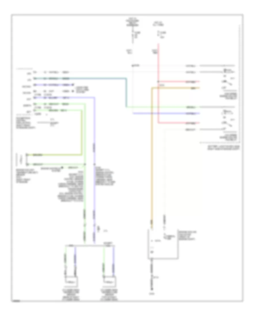
Cooling Fan Wiring Diagram for Ford Mustang GT 2013
 https://portal-diagnostov.com/license.html
Automotive Electricians Portal FZCO
Automotive Electricians Portal FZCO
https://portal-diagnostov.com/license.html
https://portal-diagnostov.com/license.html
Automotive Electricians Portal FZCO
Automotive Electricians Portal FZCOList of elements for Cooling Fan Wiring Diagram for Ford Mustang GT 2013:
- 3.7l
- 5.8l
- Battery junction box (bjb) (right side of engine compt)
- C1026
- C1381b
- C1381e
- C175b
- C175e
- Cec01
- Cec02
- Cht
- Computer data lines system
- Cylinder head temperature sensor (rear of right cylinder head)
- Cylinder head temperature sensor (top of right cylinder head)
- Ect
- Engine controls system
- Engine coolant temperature (ect) sensor (5.8l) (right front of engine)
- Engine cooling fan motor (front of engine compt)
- Except 3.7l
- Except 5.8l
- Fuse 40a
- Fuse 5a
- G100
- Hfc
- High speed engine cooling fan relay
- Hot at all times
- Hot w/ pcm power relay energized
- Hs can+
- Hs can-
- Lfc
- Low speed engine cooling fan relay
- Nca
- Powertrain control module (pcm) (right front of engine compt)
- Re141
- Re405
- S102 (except 3.7l) (5.8l: engine control sensor & fuel charge wiring harness, near breakout to ignition transformer capacitor 1) (5.0l: engine control sensor & fuel charge wiring harness, near breakout to c1019)
- S106 (except 3.7l) (engine control sensor & fuel charge wiring harness, near breakout to egr system module)
- S112
- S121
- S125
- Sigrtn
- Thermal fuse
- Vdb04
- Vdb05
- Ve712
CRUISE CONTROL
Cruise Control Wiring Diagram (1 of 2) for Ford Mustang GT 2013
 https://portal-diagnostov.com/license.html
Automotive Electricians Portal FZCO
Automotive Electricians Portal FZCO
https://portal-diagnostov.com/license.html
https://portal-diagnostov.com/license.html
Automotive Electricians Portal FZCO
Automotive Electricians Portal FZCOList of elements for Cruise Control Wiring Diagram (1 of 2) for Ford Mustang GT 2013:
- (starter motor relay & battery ground wiring harness, near breakout to heated oxygen sensor 12)
- 3.7l
- 5.0l
- 5.0l & 5.8l
- 5.8l
- Accelerator pedal position sensor (top of accelerator pedal assembly)
- App
- App2
- Apprtn
- Apprtn2
- Appvref
- Appvref2
- Battery junction box (bjb) (right side of engine compt)
- Boo
- Bps
- C110
- C1381b
- C1381e
- C1381t
- C175b
- C175e
- C175t
- C211
- C215
- Case gnd
- Ccb08
- Ce412
- Ce426
- Ce509
- Ce903
- Ce904
- Computer data lines system
- Cpp
- Electronic throttle control module (on throttle body)
- Electronic throttle control motor (5.8l)
- Engine controls system
- Etcref
- Etcrtn
- Fuse 10a
- G103 (right front of engine compt)
- Gd119
- Hot at all times
- Hs can +
- Hs can -
- Kapwr
- Le111
- Le134
- Le136
- Le137
- Oss
- Output shaft speed sensor (5.8l) (right rear of transmission)
- Powertrain control module (pcm) (right front of engine compt)
- Re134
- Re136
- Re137
- Re406
- Res08
- Ret24
- S138
- S143
- Sbb23
- Sccs
- Sccs return
- Sig rtn
- Sw man trans
- Tacm+
- Tacm-
- Throttle position sensor (5.8l) (throttle body assembly)
- Tp1
- Tp2
- Tr gnd
- Tss
- Vdb04
- Vdb05
- Ve701
- Ve702
- Ve818
- Ve819
- Ves10
- Vet26
- Vet33
- Vpwr
Cruise Control Wiring Diagram (2 of 2) for Ford Mustang GT 2013
 https://portal-diagnostov.com/license.html
Automotive Electricians Portal FZCO
Automotive Electricians Portal FZCO
https://portal-diagnostov.com/license.html
https://portal-diagnostov.com/license.html
Automotive Electricians Portal FZCO
Automotive Electricians Portal FZCOList of elements for Cruise Control Wiring Diagram (2 of 2) for Ford Mustang GT 2013:
- (right front of engine compt)
- A/t
- Body control module b (right rear of luggage compt)
- Bpp
- Brake pedal position (bpp) switch (top of brake pedal assembly)
- C211
- C215
- C2274a
- C2274b
- C2280b
- C265
- C4368a
- Ccb08
- Clock spring (below steering wheel)
- Clutch pedal cruise control deactivator switch (m/t) (clutch pedal support)
- Clutch pedal position switch (m/t) (clutch pedal bracket)
- Computer data lines system
- G102
- G104
- Instrument panel cluster (ipc)
- Interior lights system
- Left steering wheel switch
- M/t
- Micro
- Ms can +
- Ms can -
- Nca
- On/off
- Oss
- Output shaft speed (oss) sensor (right rear of transmission)
- Resume
- S113
- S115
- S213 (body main wiring harness, near breakout to c211)
- Set +
- Set -
- Smart junction box (sjb) (right kick panel)
- Tr gnd
- Transmission (6r80) (right side of transmission)
- Tss
- Vpwr
- W/ 5-button message center
DEFOGGERS
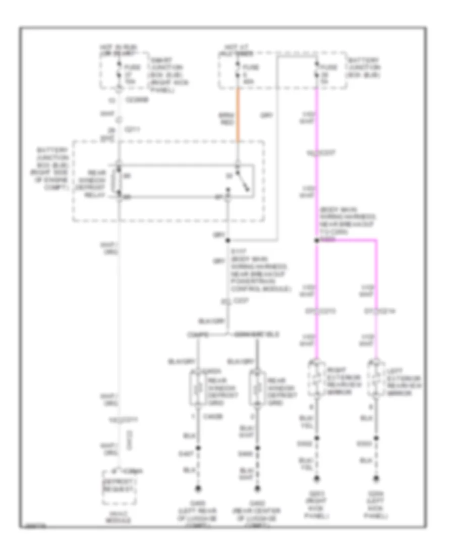
Defoggers Wiring Diagram for Ford Mustang GT 2013
 https://portal-diagnostov.com/license.html
Automotive Electricians Portal FZCO
Automotive Electricians Portal FZCO
https://portal-diagnostov.com/license.html
https://portal-diagnostov.com/license.html
Automotive Electricians Portal FZCO
Automotive Electricians Portal FZCOList of elements for Defoggers Wiring Diagram for Ford Mustang GT 2013:
- (body main wiring harness, near breakout to c260) s223
- Battery junction box (bjb)
- Battery junction box (bjb) (right side of engine compt)
- C211
- C213 d7
- C214 d7
- C2280b
- C237
- C294a
- C402a
- C402b
- Ch122
- Convertible
- Coupe
- Defrost request
- Fuse 10a
- Fuse 40a
- Fuse 5a
- G203 (right kick panel)
- G204 (left kick panel)
- G400 (left rear of luggage compt)
- G402 (rear center of luggage compt)
- Hot at all times
- Hot in run or start
- Hvac module
- Left exterior rearview mirror
- Rear window defrost grid
- Rear window defrost relay
- Right exterior rearview mirror
- S400
- S407
- S503
- S602
- Smart junction box (sjb) (right kick panel)
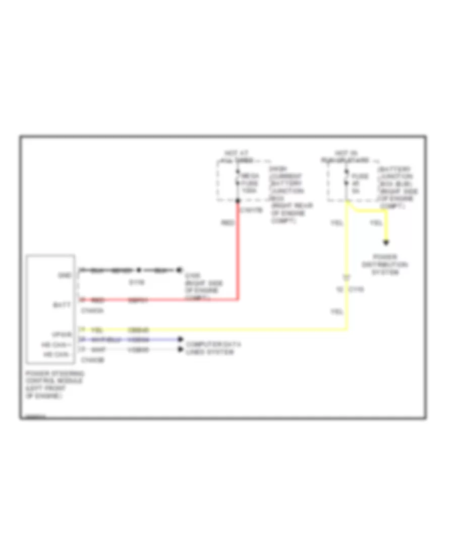
ELECTRONIC POWER STEERING
Electronic Power Steering Wiring Diagram for Ford Mustang GT 2013
 https://portal-diagnostov.com/license.html
Automotive Electricians Portal FZCO
Automotive Electricians Portal FZCO
https://portal-diagnostov.com/license.html
https://portal-diagnostov.com/license.html
Automotive Electricians Portal FZCO
Automotive Electricians Portal FZCOList of elements for Electronic Power Steering Wiring Diagram for Ford Mustang GT 2013:
- Batt
- Battery junction box (bjb) (right side of engine compt)
- C110
- C1463a
- C1463b
- C1617b
- Cbb45
- Computer data lines system
- Fuse 5a
- G105 (right side of engine compt)
- Gd125
- Gnd
- High current battery junction box (right rear of engine compt)
- Hot at all times
- Hot in run or start
- Hs can +
- Hs can -
- Mega fuse 100a
- Power distribution system
- Power steering control module (left front of engine)
- Red
- S118
- Sbf01
- Vdb04
- Vdb05
- Vpwr
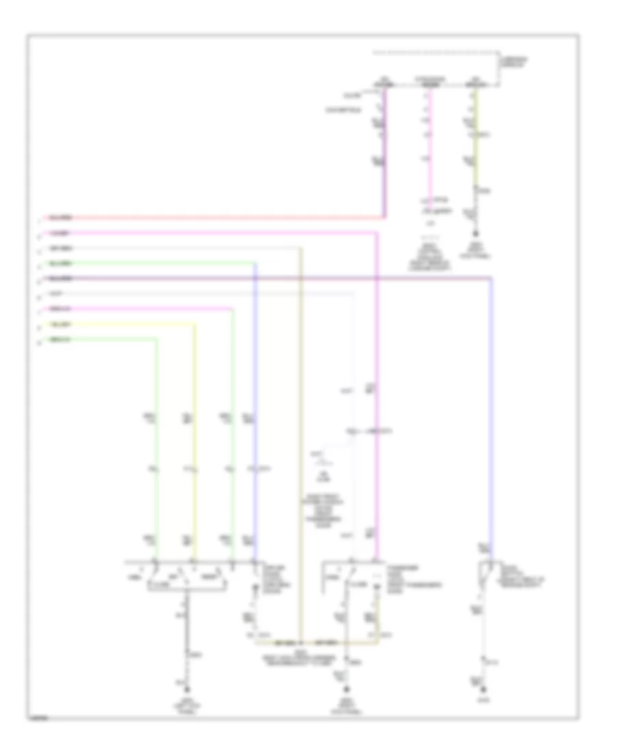
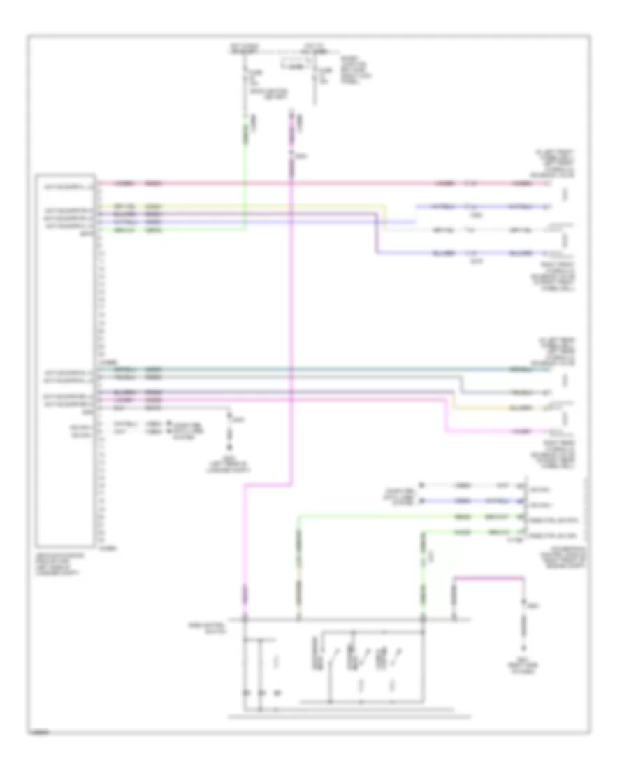
ELECTRONIC SUSPENSION
Electronic Suspension Wiring Diagram for Ford Mustang GT 2013
 https://portal-diagnostov.com/license.html
Automotive Electricians Portal FZCO
Automotive Electricians Portal FZCO
https://portal-diagnostov.com/license.html
https://portal-diagnostov.com/license.html
Automotive Electricians Portal FZCO
Automotive Electricians Portal FZCOList of elements for Electronic Suspension Wiring Diagram for Ford Mustang GT 2013:
- (in left front wheelwell) left front hydraulic solenoid valve
- (in left rear wheelwell) left rear hydraulic solenoid valve
- Active dmpr fl hi
- Active dmpr fl lo
- Active dmpr fr hi
- Active dmpr fr lo
- Active dmpr rl hi
- Active dmpr rl lo
- Active dmpr rr hi
- Active dmpr rr lo
- Backlighting led (fet)
- C175b
- C211
- C219
- C2280b
- C2280d
- C264
- C4396a
- C4396b
- Cbp32
- Ccd03
- Ccd04
- Ccd05
- Ccd06
- Cmc29
- Computer data lines system
- Control launch
- Fuse 10a
- Fuse 15a
- G201 (right side of dash)
- G400 (left rear of luggage compt)
- Gd109
- Gnd
- Hot at all times
- Hot in run or start
- Hs can +
- Hs can -
- Isp-r
- Micro
- Powertrain control module (right front of engine compt)
- Rcd03
- Rcd04
- Rcd05
- Rcd06
- Re405
- Ride control switch
- Ride ctrl sw rtn
- Ride ctrl sw sig
- Right front hydraulic solenoid valve (in right front wheelwell)
- Right rear hydraulic solenoid valve (in right rear wheelwell)
- S201
- S224
- S407
- Smart junction box (sjb) (right kick panel)
- Steering mode
- Suspension mode
- Vdb04
- Vdb05
- Vehicle dynamics module (vdm) (left side of luggage compt)
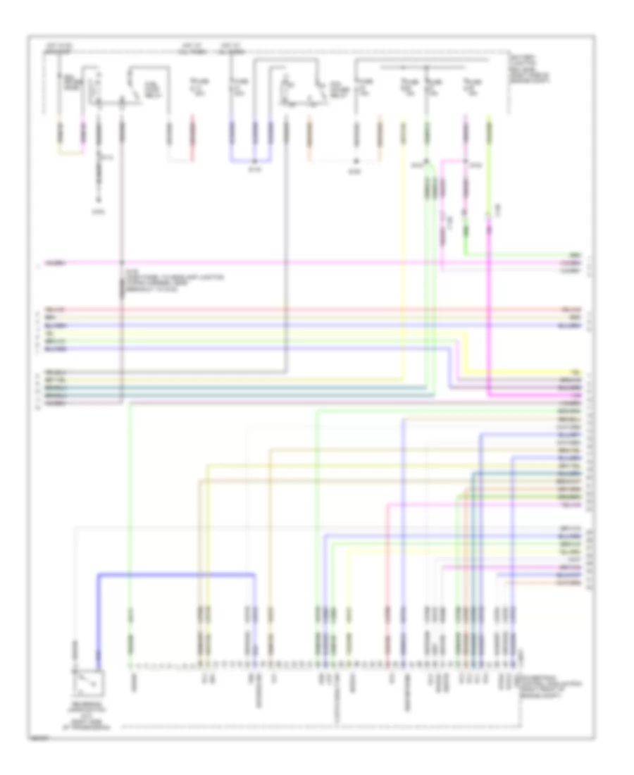
ENGINE PERFORMANCE
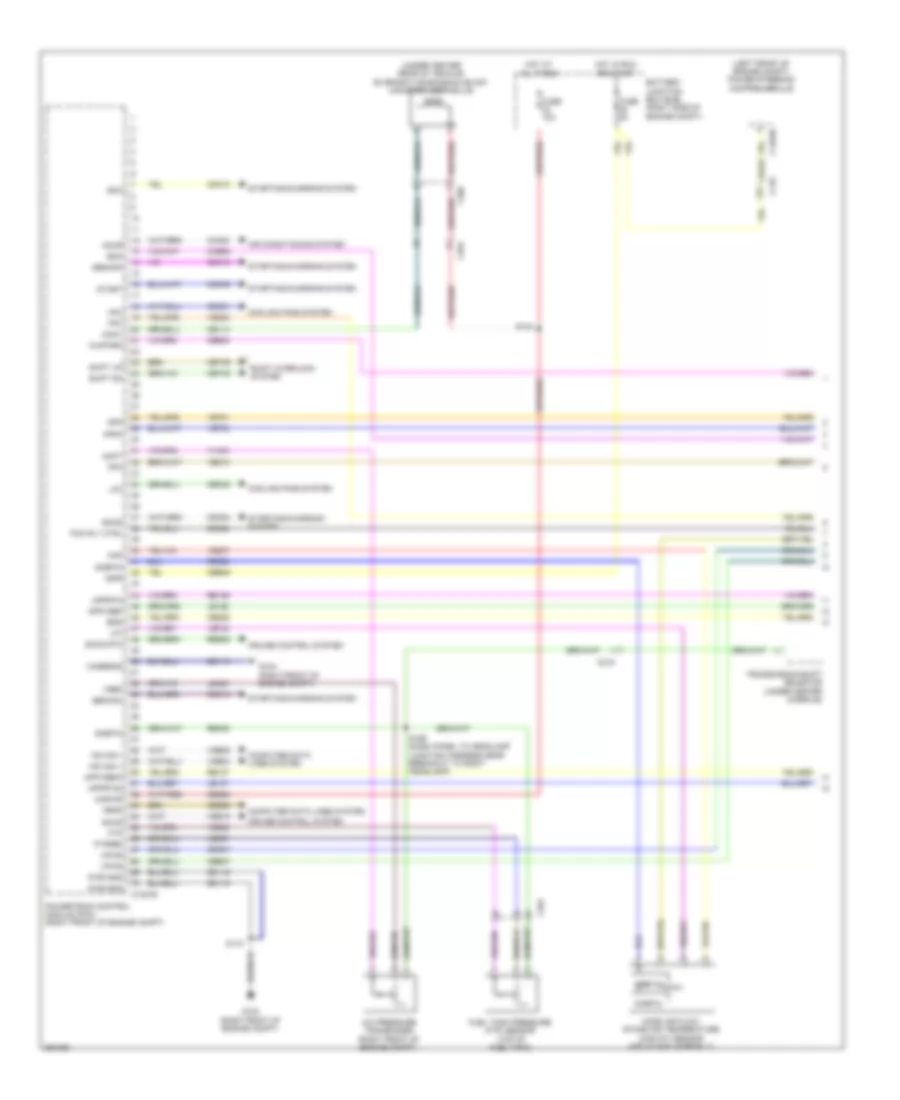
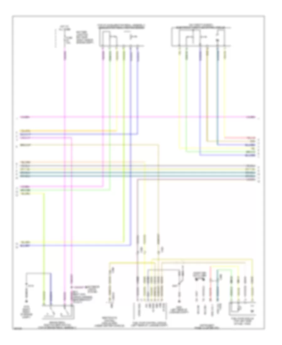
3.7L
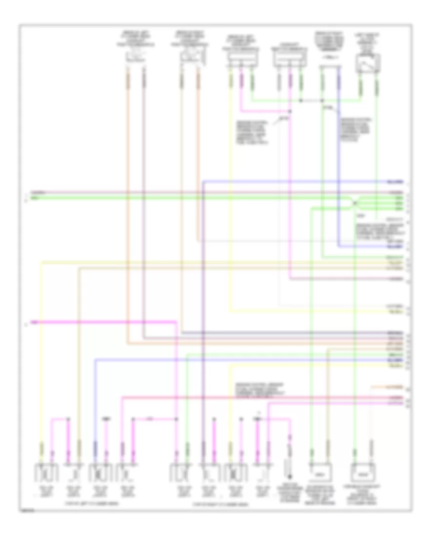
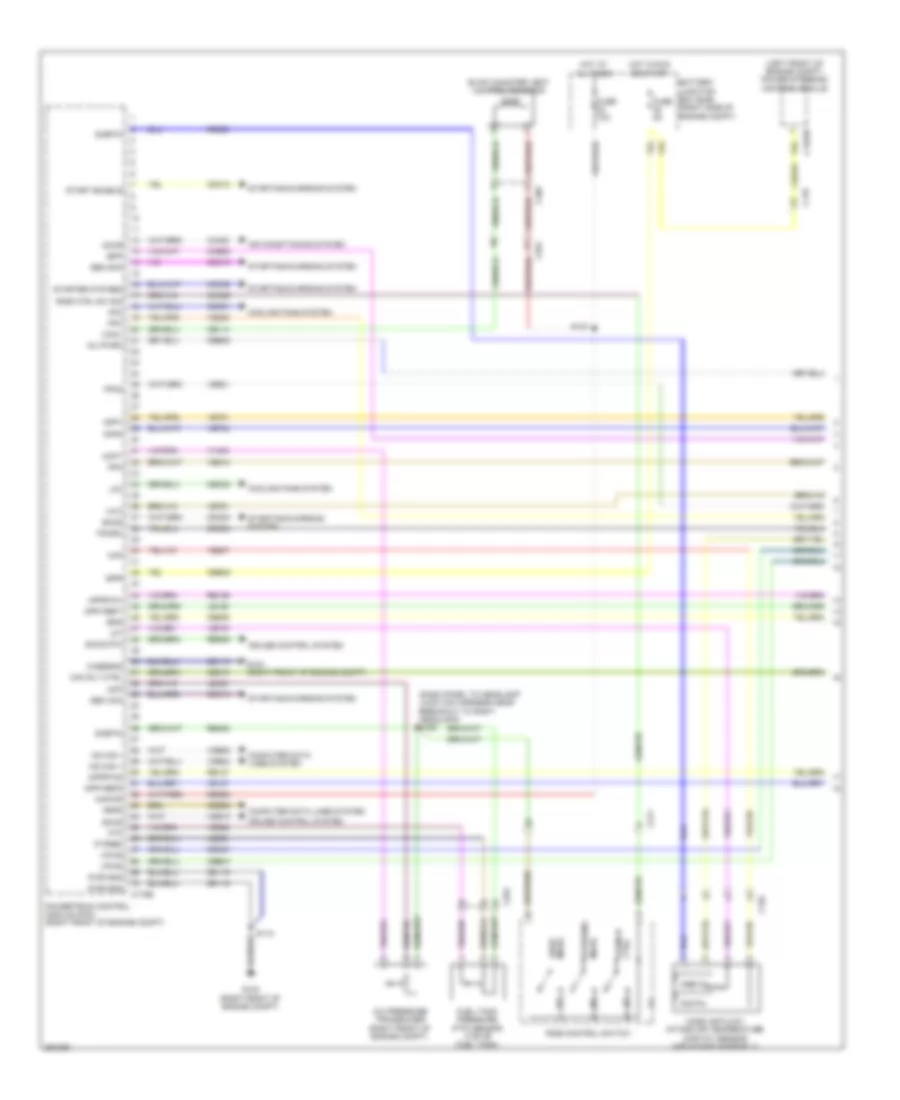
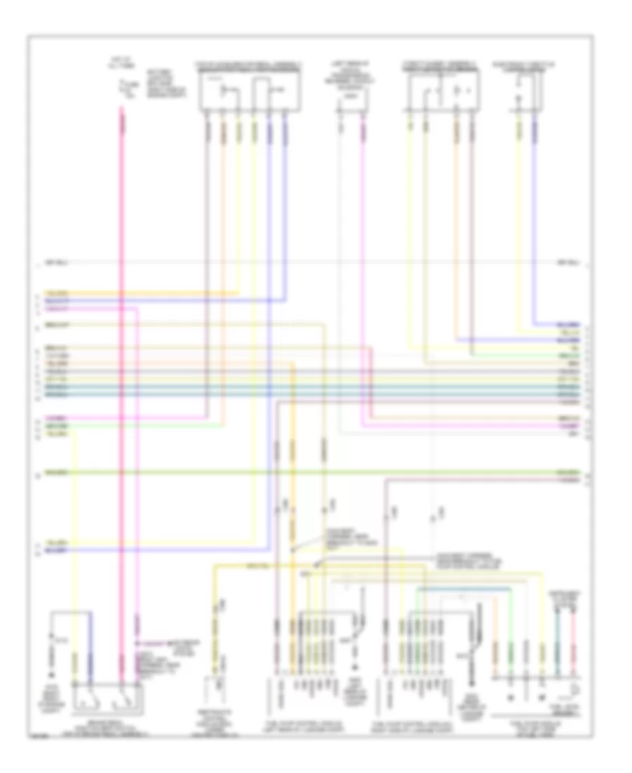
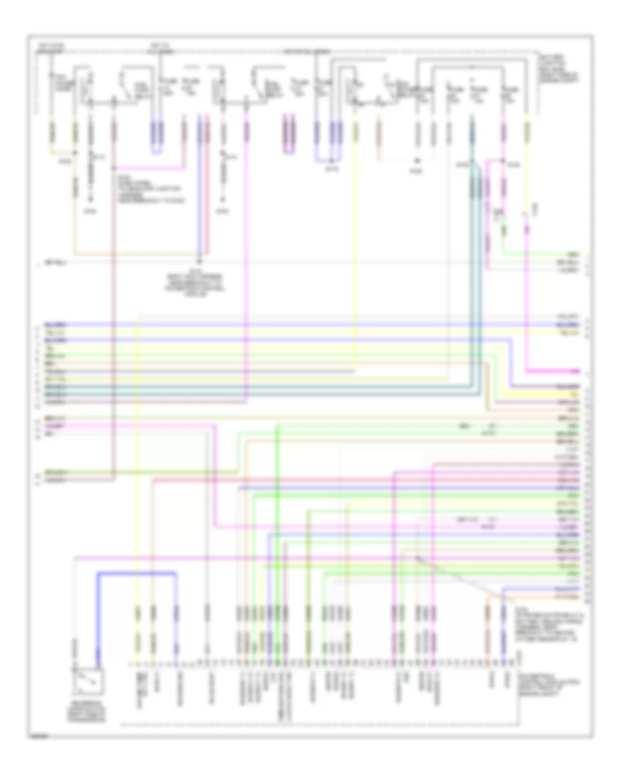
3.7L, Engine Performance Wiring Diagram (1 of 6) for Ford Mustang GT 2013
 https://portal-diagnostov.com/license.html
Automotive Electricians Portal FZCO
Automotive Electricians Portal FZCO
https://portal-diagnostov.com/license.html
https://portal-diagnostov.com/license.html
Automotive Electricians Portal FZCO
Automotive Electricians Portal FZCOList of elements for 3.7L, Engine Performance Wiring Diagram (1 of 6) for Ford Mustang GT 2013:
- (left front of engine compt) power steering control module
- (under center rear of vehicle) evaporative emission (evap) canister vent valve
- A/c pressure transducer (right front of engine compt)
- Accr
- Acpt
- Air conditioning system
- App
- App2
- Apprtn
- Apprtn2
- Appvref
- Appvref2
- Battery junction box (bjb) (right side of engine compt)
- Boo
- Bps
- C110
- C1381b
- C1463b
- C219
- C264
- C406
- Canv
- Casegnd
- Cbb45
- Cbb47
- Ccb08
- Cdb08
- Cdc10
- Cdc12
- Cdc15
- Cdc35
- Cdc54
- Ce114
- Ce302
- Ce509
- Ce608
- Cec01
- Cec02
- Cet35
- Cet42
- Ch302
- Computer data lines system
- Cooling fans system
- Cruise control system
- Digital
- Feps
- Fpc
- Fpm
- Ftp
- Ftpref
- Fuel tank pressure (ftp) sensor (top of fuel tank)
- Fuse 10a
- Fuse 5a
- G102 (right front of engine compt)
- G103 (right front of engine compt)
- Gd119
- Gencom
- Genmon
- Hfc
- Hot at all times
- Hot in run or start
- Hs can +
- Hs can -
- Iat
- Injpwrm
- Ispr
- Kapwr
- Le136
- Le137
- Le230
- Le423
- Lfc
- Maf
- Mass air flow/ intake air temperature (maf/iat) sensor (air intake assembly)
- Pcm rly ctrl
- Powertrain control module (pcm) (right front of engine compt)
- Pwr gnd
- Re136
- Re137
- Re320
- Re405
- Res08
- S115
- S143
- S199 (dash panel to headlamp junction harness near breakout to right headlamp)
- Sbb23
- Sccs
- Sccs rtn
- Shift dn
- Shift interlock system
- Shift up
- Sigrtn
- Smc
- Smcs
- Start
- Starting/charging system
- Transmission shift selector (under center console)
- Vdb04
- Vdb05
- Ve225
- Ve518
- Ve701
- Ve702
- Ve740
- Ve807
- Ve922
- Ves10
- Vh433
- Vpwr
- Vref
- Vref 5v
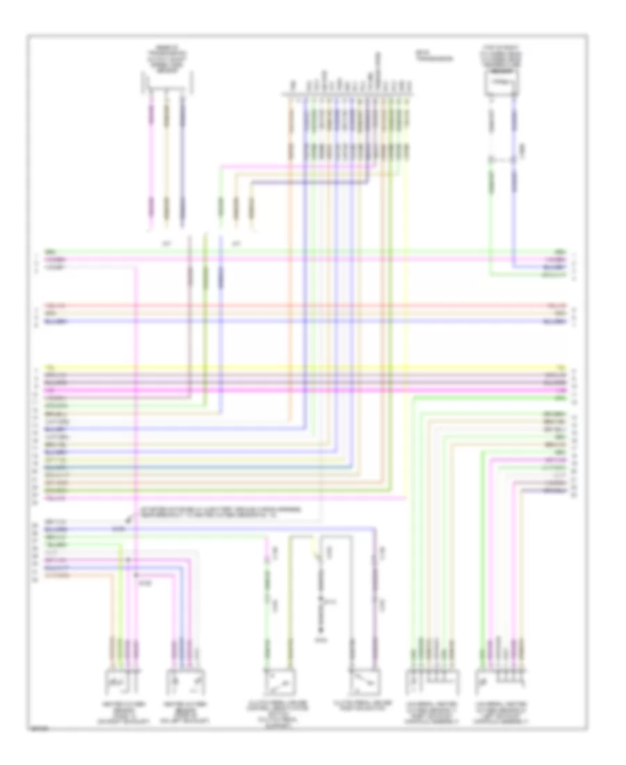
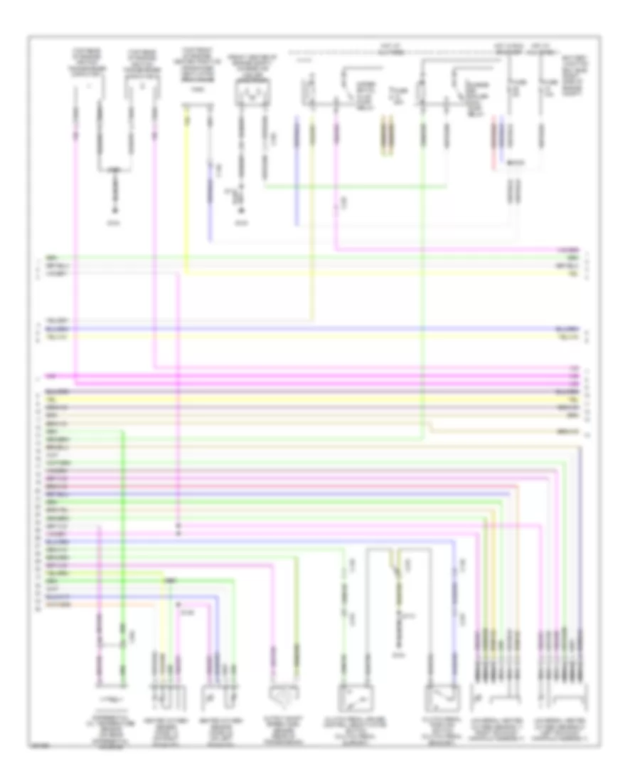
3.7L, Engine Performance Wiring Diagram (2 of 6) for Ford Mustang GT 2013
 https://portal-diagnostov.com/license.html
Automotive Electricians Portal FZCO
Automotive Electricians Portal FZCO
https://portal-diagnostov.com/license.html
https://portal-diagnostov.com/license.html
Automotive Electricians Portal FZCO
Automotive Electricians Portal FZCOList of elements for 3.7L, Engine Performance Wiring Diagram (2 of 6) for Ford Mustang GT 2013:
- (on throttle body) electronic throttle control module
- (top of accelerator pedal assembly) accelerator pedal position sensor
- 1 rtn
- Battery junction box (bjb) (right side of engine compt)
- Brake pedal position (bpp) switch (top of brake pedal assembly)
- C2041a
- C260
- C264
- C265
- Ce515
- Ce608
- Computer data lines system
- Cr113
- Ens
- Exterior lights system
- Fp pwr
- Fp rtn
- Fpc
- Fpm
- Fuel lvl
- Fuel lvl 1
- Fuel pump control module (left rear of luggage compt)
- Fuel pump module (top left side of fuel tank)
- Fuse 10a
- G102 (right front of engine compt)
- G400 (left rear of luggage compt)
- Gd109
- Gnd
- Hot at all times
- Hs can +
- Hs can -
- Instrument panel cluster (ipc)
- Nca
- Re515
- Restraints control module (rcm) (under center console)
- Rmc32
- S115
- S213 (body main wiring harness, near breakout to c211)
- S407
- Ve225
- Ve518
- Vmc11
- Vpwr fuel
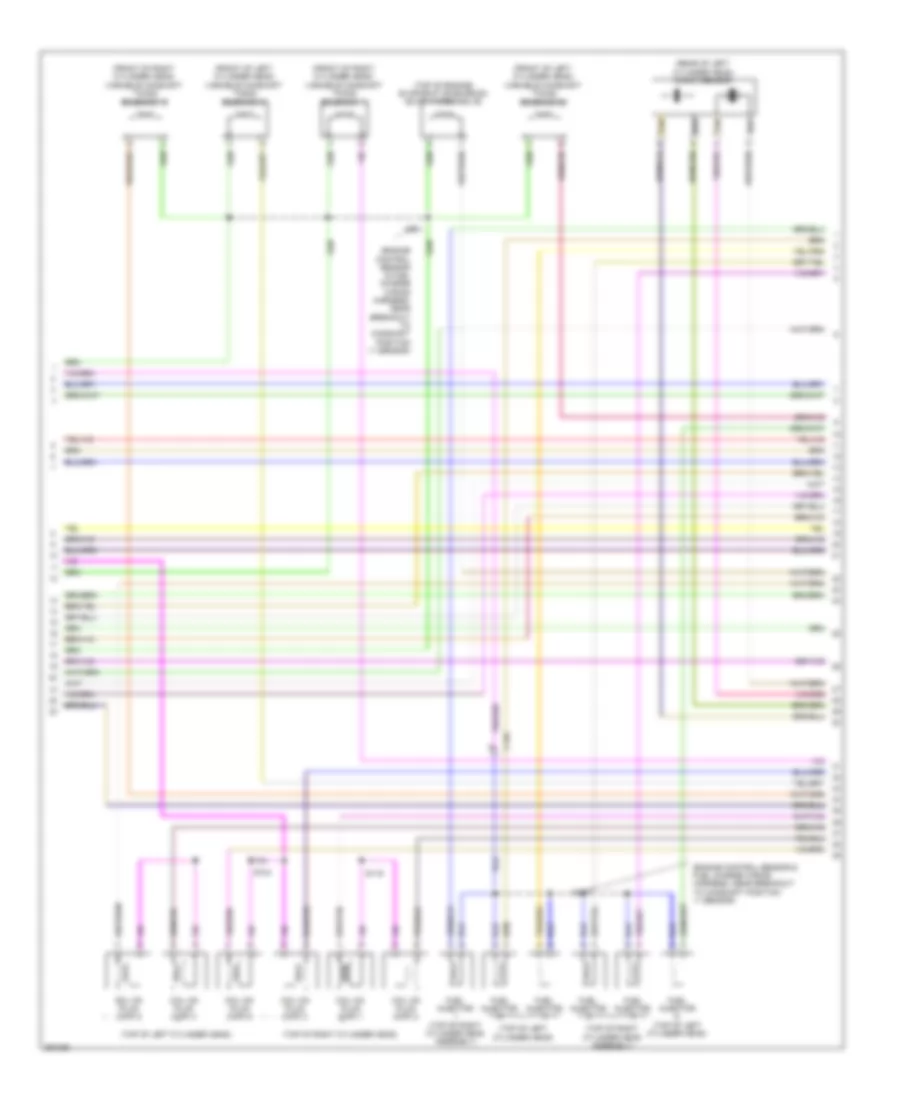
3.7L, Engine Performance Wiring Diagram (3 of 6) for Ford Mustang GT 2013
 https://portal-diagnostov.com/license.html
Automotive Electricians Portal FZCO
Automotive Electricians Portal FZCO
https://portal-diagnostov.com/license.html
https://portal-diagnostov.com/license.html
Automotive Electricians Portal FZCO
Automotive Electricians Portal FZCOList of elements for 3.7L, Engine Performance Wiring Diagram (3 of 6) for Ford Mustang GT 2013:
- Battery junction box (bjb) (right side of engine compt)
- C110
- C1381t
- C146
- Ce233
- Ce234
- Ce903
- Ce904
- Cet05
- Cet06
- Cet07
- Cet08
- Cet09
- Cet10
- Cet18
- Cet25
- Cet47
- Cet60
- Clutch deact sw
- Cpp
- Fuel pump relay
- Fuse 15a
- Fuse 20a
- Fuse 30a
- G100
- Ho2s12
- Ho2s22
- Hot at all times
- Hot in on or start
- Htr12
- Htr22
- Le111
- Oss
- Pc1
- Pc2
- Pc3
- Pc4
- Pc5
- Pc6
- Pcm power diode
- Pcm power relay
- Powertrain control module (pcm) (right front of engine compt)
- Re406
- Ret24
- Reverse sw
- Reversing lamps switch (m/t) (right side of transmission)
- S112
- S116
- S120
- S123
- S124
- S135 (dash panel to headlamp junction wiring harness, near breakout to g100)
- Sigrtn
- Sigrtn/trgnd
- Ss1
- Tft
- Tr p
- Tspc
- Tss
- Vbpwr
- Ve731
- Ve733
- Vet26
- Vet27
- Vet33
3.7L, Engine Performance Wiring Diagram (4 of 6) for Ford Mustang GT 2013
 https://portal-diagnostov.com/license.html
Automotive Electricians Portal FZCO
Automotive Electricians Portal FZCO
https://portal-diagnostov.com/license.html
https://portal-diagnostov.com/license.html
Automotive Electricians Portal FZCO
Automotive Electricians Portal FZCOList of elements for 3.7L, Engine Performance Wiring Diagram (4 of 6) for Ford Mustang GT 2013:
- (rear of transmission) output shaft speed (oss) sensor
- (starter motor relay & battery ground wiring harness, near breakout to heated oxygen sensor no. 12)
- (top of right cylinder head) cylinder head temperature sensor
- 6r 80 transmission
- A/t
- C1026
- C110
- C215
- Cet05
- Cet06
- Cet07
- Cet08
- Cet09
- Cet10
- Cet18
- Cet25
- Cet60
- Clutch pedal cruise control deactivator switch (clutch pedal support)
- Clutch pedal cruise position switch
- G104
- Heated oxygen sensor (ho2s) 12 (on right exhaust)
- Heated oxygen sensor (ho2s) 22 (on left exhaust)
- Le111
- M/t
- Oss
- Pc1
- Pc2
- Pc3
- Pc4
- Pc5
- Pc6
- Re406
- Ret24
- S113
- S138
- S139
- Sig rtn
- Ss1
- Tft
- Tr gnd
- Tr p
- Tspc
- Tss
- Tss/oss vpwr
- Universal heated oxygen sensor 11 (right exhaust manifold assembly)
- Universal heated oxygen sensor 21 (left exhaust manifold assembly)
- Vet26
- Vet27
- Vet33
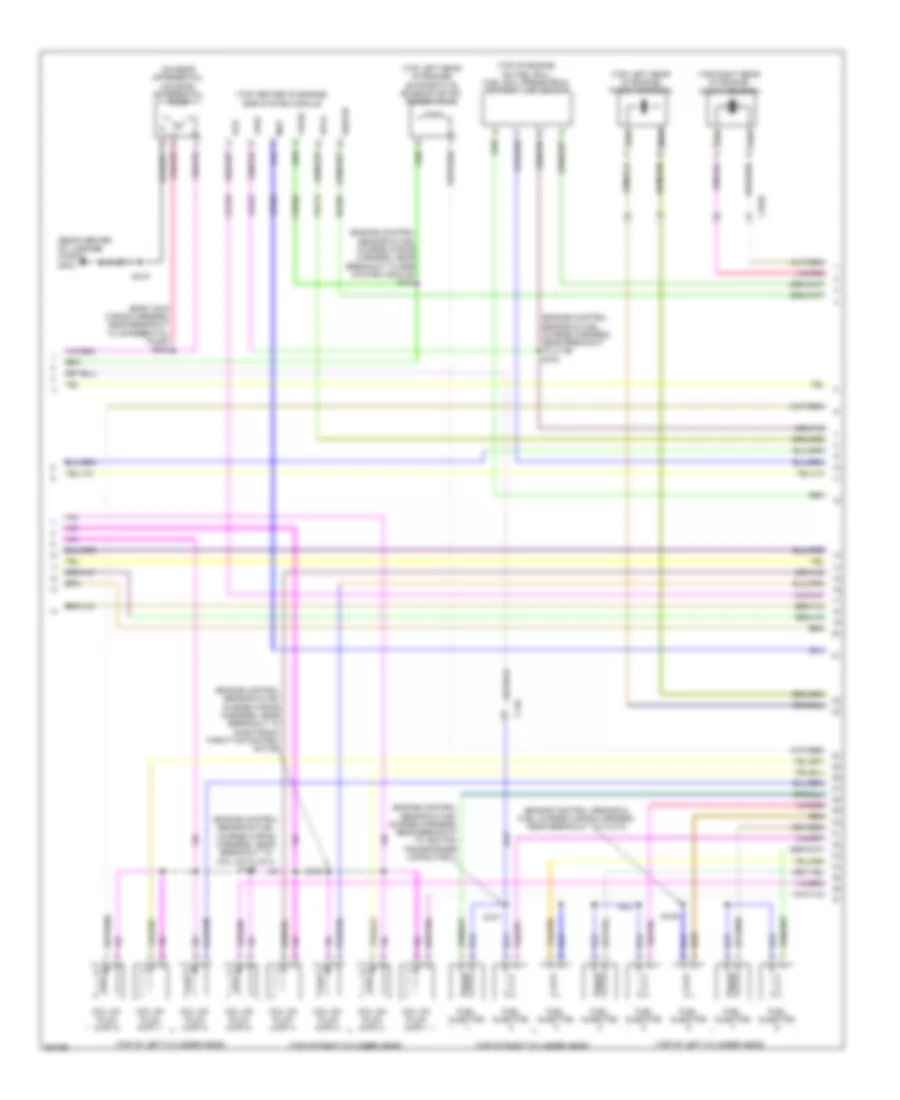
3.7L, Engine Performance Wiring Diagram (5 of 6) for Ford Mustang GT 2013
 https://portal-diagnostov.com/license.html
Automotive Electricians Portal FZCO
Automotive Electricians Portal FZCO
https://portal-diagnostov.com/license.html
https://portal-diagnostov.com/license.html
Automotive Electricians Portal FZCO
Automotive Electricians Portal FZCOList of elements for 3.7L, Engine Performance Wiring Diagram (5 of 6) for Ford Mustang GT 2013:
- (engine control sensor & fuel charge wiring harness, near breakout to camshaft position 11 sensor)
- (front of left cylinder head) variable camshaft timing solenoid 21
- (front of left cylinder head) variable camshaft timing solenoid 22
- (front of right cylinder head) variable camshaft timing solenoid 11
- (front of right cylinder head) variable camshaft timing solenoid 12
- (rear of left cylinder head) knock sensor
- (top of engine) evaporative emission (evap) purge valve
- (top of left cylinder head)
- (top of right cylinder head assembly)
- (top of right cylinder head)
- C146
- Coil on plug (cop) 1
- Coil on plug (cop) 2
- Coil on plug (cop) 3
- Coil on plug (cop) 4
- Coil on plug (cop) 5
- Coil on plug (cop) 6
- Fuel injector
- Fuel injector (top of left cylinder head)
- Fuel injector (top of right cylinder head assembly)
- S101
- S104
- S107
- S119
- Tan
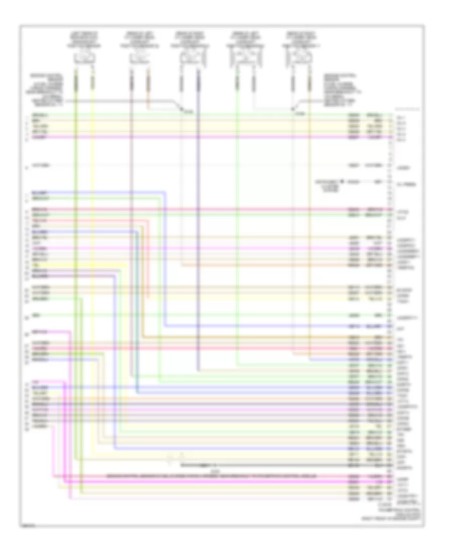
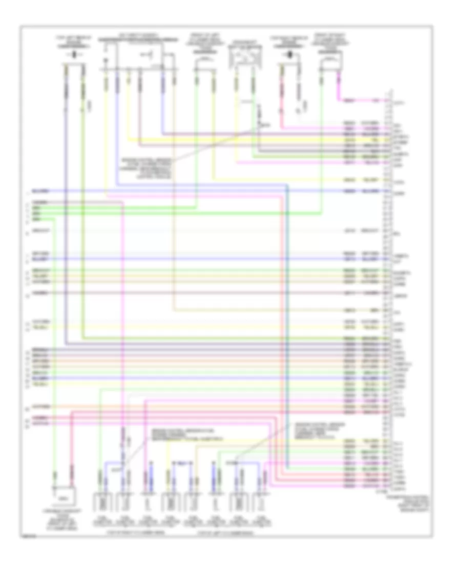
3.7L, Engine Performance Wiring Diagram (6 of 6) for Ford Mustang GT 2013
 https://portal-diagnostov.com/license.html
Automotive Electricians Portal FZCO
Automotive Electricians Portal FZCO
https://portal-diagnostov.com/license.html
https://portal-diagnostov.com/license.html
Automotive Electricians Portal FZCO
Automotive Electricians Portal FZCOList of elements for 3.7L, Engine Performance Wiring Diagram (6 of 6) for Ford Mustang GT 2013:
- (engine control sensor & fuel charge wiring harness, near breakout to powertrain control module)
- (engine control sensor & fuel charge wiring harness, near breakout to universal heated oxygen sensor no. 11)
- (left rear of engine block) crankshaft position sensor
- (rear of left cylinder head) camshaft position sensor 21
- (rear of left cylinder head) camshaft position sensor 22
- (rear of right cylinder head) camshaft position sensor 11
- (rear of right cylinder head) camshaft position sensor 12
- C1381e
- Ce113
- Ce205
- Ce206
- Ce207
- Ce208
- Ce209
- Ce210
- Ce235
- Ce236
- Ce303
- Ce304
- Ce305
- Ce306
- Ce307
- Ce308
- Ce412
- Ce421
- Ce422
- Ce426
- Ce442
- Ce443
- Cht
- Ckp+
- Ckp-
- Cmc24
- Cmp11
- Cmp12
- Cmp21
- Cmp22
- Cop1a
- Cop2c
- Cop3e
- Cop4b
- Cop5d
- Cop6f
- De135
- Etcref
- Etcrtn
- Evapcp
- Inj 1
- Inj 2
- Inj 3
- Inj 4
- Inj 5
- Inj 6
- Instrument cluster system
- Ks1+
- Ks1-
- Ks2+
- Ks2-
- Le134
- Le448
- Le449
- Le450
- Le451
- Le452
- Le453
- Nca
- Oil press
- Powertrain control module (pcm) (right front of engine compt)
- Re134
- Re135
- Re323
- Re324
- Re405
- Re429
- S108
- S145
- S146
- Shdrtn
- Sigrtn
- Tacm+
- Tacm-
- Tp1
- Tp2
- Uo2s11
- Uo2s21
- Uo2sgref11
- Uo2sgref21
- Uo2shtr11
- Uo2shtr21
- Uo2spc11
- Uo2spc21
- Uo2spct11
- Uo2spct21
- Vct11
- Vct12
- Vct21
- Vct22
- Ve706
- Ve707
- Ve711
- Ve712
- Ve801
- Ve802
- Ve818
- Ve819
- Ve826
- Ve827
- Vrsrtn
- Vrsrtn2
5.0L
5.0L, Engine Performance Wiring Diagram (1 of 6) for Ford Mustang GT 2013
 https://portal-diagnostov.com/license.html
Automotive Electricians Portal FZCO
Automotive Electricians Portal FZCO
https://portal-diagnostov.com/license.html
https://portal-diagnostov.com/license.html
Automotive Electricians Portal FZCO
Automotive Electricians Portal FZCOList of elements for 5.0L, Engine Performance Wiring Diagram (1 of 6) for Ford Mustang GT 2013:
- (dash panel to headlamp junction harness near breakout to right headlamp)
- A/c pressure transducer (right front of engine compt)
- Accelerator pedal position sensor (top of accelerator pedal assembly)
- Accr
- Acpt
- Air conditioning system
- App1
- App2
- Apprtn1
- Apprtn2
- Appvref2
- Appvrfe1
- Battery junction box (bjb) (right side of engine compt)
- Bpp
- Bps
- C175b
- C219
- C264
- Canv
- Case gnd
- Cbb45
- Cbb47
- Ccb08
- Cdb08
- Cdc10
- Cdc12
- Cdc15
- Cdc35
- Cdc54
- Ce114
- Ce302
- Ce509
- Ce608
- Cec01
- Cec02
- Cet35
- Cet42
- Ch302
- Computer data lines system
- Computer data lines system cruise control system
- Cooling fans system
- Cruise control system
- Digital
- Feps
- Fpc
- Fpm
- Ftp
- Ftpref
- Fuse 10a
- Fuse 5a
- G102 (right front of engine compt)
- G103 (right front of engine compt)
- Gd119
- Gencom
- Genmon
- Hfc
- Hot at all times
- Hot in start or run
- Hs can +
- Hs can -
- Iat
- Injpwrm
- Ispr
- Kapwr
- Le136
- Le137
- Le230
- Le423
- Lfc
- Maf
- Mass air flow/ intake air temperature (maf/iat) sensor (air intake assembly)
- Pcmrc
- Power distribution system
- Powertrain control module (pcm) (right front of engine compt)
- Pwr gnd
- Re136
- Re137
- Re320
- Re405
- Res08
- S115
- S143
- S199
- Sbb23
- Sccs
- Sccs rtn
- Shift dn
- Shift interlock system
- Shift up
- Sigrtn
- Smc
- Smcs
- Start
- Starting/charging system
- Transmission shift selector (under center console)
- Vdb04
- Vdb05
- Ve225
- Ve518
- Ve701
- Ve702
- Ve740
- Ve807
- Ve922
- Ves10
- Vh433
- Vpwr
- Vref
- Vref 5v
5.0L, Engine Performance Wiring Diagram (2 of 6) for Ford Mustang GT 2013
 https://portal-diagnostov.com/license.html
Automotive Electricians Portal FZCO
Automotive Electricians Portal FZCO
https://portal-diagnostov.com/license.html
https://portal-diagnostov.com/license.html
Automotive Electricians Portal FZCO
Automotive Electricians Portal FZCOList of elements for 5.0L, Engine Performance Wiring Diagram (2 of 6) for Ford Mustang GT 2013:
- (under center rear of vehicle) evaporative emission (evap) canister vent valve
- Battery junction box (bjb) (right side of engine compt)
- Brake pedal position (bpp) switch (top of brake pedal assembly)
- C2041a
- C260
- C264
- C265
- C406
- Ce515
- Ce608
- Cr113
- Ens
- Exterior lights system
- Fp pwr
- Fp rtn
- Fpc
- Fpm
- Fuel pump control module (left rear of luggage compt)
- Fuel pump relay
- Fuel tank pressure (ftp) sensor (top of fuel tank)
- Fuse 20a
- G100
- G102 (right front of engine compt)
- G400 (left rear of luggage compt)
- Gd109
- Gnd
- Hot at all times
- Hot in start or run
- Pcm power diode
- Re515
- Restraints control module (rcm) (under center console)
- S112
- S115
- S135 (dash panel to headlamp junction harness near breakout to g100)
- S213 (body main harness, near breakout to c211)
- S407
- Ve225
- Ve518
- Vpwr
5.0L, Engine Performance Wiring Diagram (3 of 6) for Ford Mustang GT 2013
 https://portal-diagnostov.com/license.html
Automotive Electricians Portal FZCO
Automotive Electricians Portal FZCO
https://portal-diagnostov.com/license.html
https://portal-diagnostov.com/license.html
Automotive Electricians Portal FZCO
Automotive Electricians Portal FZCOList of elements for 5.0L, Engine Performance Wiring Diagram (3 of 6) for Ford Mustang GT 2013:
- (left exhaust manifold assembly)
- Battery junction box (bjb) (right side of engine compt)
- C110
- C146
- C260
- Computer data lines system
- Fuel gauge sensor
- Fuel lel rtn
- Fuel level 1
- Fuel pump
- Fuel pump module (top left side of fuel tank)
- Fuse 15a
- Fuse 30a
- G400 (left rear of luggage compt)
- Heated oxygen sensor (ho2s) 12 (on right exhaust)
- Heated oxygen sensor (ho2s) 22 (on left exhaust)
- Hot at all times
- Hs can +
- Hs can -
- Instrument panel cluster (ic)
- Nca
- Pcm power relay
- S116
- S120
- S123
- S124
- S139
- S140
- S407
- Universal heated oxygen sensor 11 (right exhaust manifold assembly)
- Universal heated oxygen sensor 21
5.0L, Engine Performance Wiring Diagram (4 of 6) for Ford Mustang GT 2013
 https://portal-diagnostov.com/license.html
Automotive Electricians Portal FZCO
Automotive Electricians Portal FZCO
https://portal-diagnostov.com/license.html
https://portal-diagnostov.com/license.html
Automotive Electricians Portal FZCO
Automotive Electricians Portal FZCOList of elements for 5.0L, Engine Performance Wiring Diagram (4 of 6) for Ford Mustang GT 2013:
- (right rear of transmission) output shaft speed (oss) sensor
- 6r80 transmission
- A/t
- C110
- C175t
- C215
- Ce233
- Ce234
- Ce235
- Ce236
- Ce903
- Ce904
- Cet05
- Cet06
- Cet07
- Cet08
- Cet09
- Cet10
- Cet18
- Cet25
- Cet43
- Cet47
- Cet60
- Clutch deact sw
- Clutch pedal cruise control deactivator switch (m/t) (clutch pedal support)
- Clutch pedal position switch (m/t) (clutch pedal bracket)
- Cpp
- G104
- Ho2s12
- Ho2s22
- Htr12
- Htr22
- Le111
- Le448
- Le449
- Le450
- Le451
- Le452
- Le453
- M/t
- Oss
- Pc1
- Pc2
- Pc3
- Pc4
- Pc5
- Pc6
- Powertrain control module (pcm) (right front of engine compt)
- Re242
- Re406
- Ret24
- Reverse sw
- Reversing lamps switch (m/t) (right side of transmission)
- S113
- Sigrtn
- Skip shift sol
- Skip shift solenoid (m/t) (right rear of transmission)
- Ss1
- Tft
- Tr gnd
- Tr p
- Tr-p
- Tspc
- Tss
- Tss/oss vpwr
- Uo2s11
- Uo2s21
- Uo2sgref11
- Uo2sgref21
- Uo2shtr11
- Uo2shtr21
- Uo2spc11
- Uo2spc21
- Uo2spct11
- Uo2spct21
- Ve731
- Ve733
- Ve826
- Ve827
- Vet26
- Vet27
- Vet33
- Vpwr
5.0L, Engine Performance Wiring Diagram (5 of 6) for Ford Mustang GT 2013
 https://portal-diagnostov.com/license.html
Automotive Electricians Portal FZCO
Automotive Electricians Portal FZCO
https://portal-diagnostov.com/license.html
https://portal-diagnostov.com/license.html
Automotive Electricians Portal FZCO
Automotive Electricians Portal FZCOList of elements for 5.0L, Engine Performance Wiring Diagram (5 of 6) for Ford Mustang GT 2013:
- (engine control sensor & fuel charge wiring harness, near breakout to c1019)
- (engine control sensor & fuel charge wiring harness, near breakout to fuel injector 1)
- (engine control sensor & fuel charge wiring harness, near breakout to fuel injector 3)
- (engine control sensor & fuel charge wiring harness, near breakout to fuel injector 4)
- (left side of oil pan assembly) low oil level switch
- (rear of left cylinder head) camshaft position sensor 21
- (rear of left cylinder head) camshaft position sensor 22
- (rear of right cylinder head) camshaft position sensor 12
- (rear of right cylinder head) cylinder head temperature sensor
- (top of left cylinder head)
- (top of right cylinder head)
- Camshaft position sensor 11
- Coil on plug (cop) 1
- Coil on plug (cop) 2
- Coil on plug (cop) 3
- Coil on plug (cop) 4
- Coil on plug (cop) 5
- Coil on plug (cop) 6
- Coil on plug (cop) 7
- Coil on plug (cop) 8
- Evaporative emission (evap) purge valve (top left rear of engine)
- Ignition transformer capacitor 1 (top rear of engine)
- S101
- S102
- S104
- S119
- S136
- Variable camshaft timing solenoid 12 (front of right cylinder head)
5.0L, Engine Performance Wiring Diagram (6 of 6) for Ford Mustang GT 2013
 https://portal-diagnostov.com/license.html
Automotive Electricians Portal FZCO
Automotive Electricians Portal FZCO
https://portal-diagnostov.com/license.html
https://portal-diagnostov.com/license.html
Automotive Electricians Portal FZCO
Automotive Electricians Portal FZCOList of elements for 5.0L, Engine Performance Wiring Diagram (6 of 6) for Ford Mustang GT 2013:
- (engine control sensor & fuel charge harness, near breakout to fuel injector 3)
- (engine control sensor & fuel charge wiring harness, near breakout to c1313)
- (engine control sensor & fuel charge wiring harness, near breakout to powertrain control module)
- (front of left cylinder head) variable camshaft timing solenoid 21
- (front of right cylinder head) variable camshaft timing solenoid 11
- (on throttle body) electronic throttle control module
- (top left rear of engine) knock sensor 2
- (top of left cylinder bank)
- (top of right cylinder head)
- (top right rear of engine) knock sensor 1
- C1019
- C146
- C175e
- Ce113
- Ce205
- Ce206
- Ce207
- Ce208
- Ce209
- Ce210
- Ce211
- Ce212
- Ce303
- Ce304
- Ce305
- Ce306
- Ce307
- Ce308
- Ce309
- Ce310
- Ce412
- Ce421
- Ce422
- Ce426
- Ce442
- Ce443
- Cht
- Ckp+
- Ckp-
- Cmp11
- Cmp12
- Cmp21
- Cmp22
- Cop1a
- Cop2h
- Cop3f
- Cop4c
- Cop5b
- Cop6e
- Cop7g
- Cop8d
- Crankshaft position sensor
- De135
- E-sigrtn
- Eol
- Etcref
- Etcrtn
- Evapcp
- Fuel injector
- Inj 1
- Inj 2
- Inj 3
- Inj 4
- Inj 5
- Inj 6
- Inj 7
- Inj 8
- Ks1+
- Ks1-
- Ks2+
- Ks2-
- Le111
- Le134
- Le142
- Nca
- Powertrain control module (pcm) (right front of engine compt)
- Re134
- Re135
- Re323
- Re324
- Re405
- Re429
- S107
- S108
- S109
- Shdrtn
- Tacm+
- Tacm-
- Tp1
- Tp2
- Variable camshaft timing solenoid 22 (front of left cylinder head)
- Vbpwr
- Vct11
- Vct12
- Vct21
- Vct22
- Ve706
- Ve707
- Ve711
- Ve712
- Ve736
- Ve738
- Ve801
- Ve802
- Ve818
- Ve819
- Vrsrtn
- Vrsrtn 2
5.8L SUPERCHARGED
5.8L Supercharged, Engine Performance Wiring Diagram (1 of 6) for Ford Mustang GT 2013
 https://portal-diagnostov.com/license.html
Automotive Electricians Portal FZCO
Automotive Electricians Portal FZCO
https://portal-diagnostov.com/license.html
https://portal-diagnostov.com/license.html
Automotive Electricians Portal FZCO
Automotive Electricians Portal FZCOList of elements for 5.8L Supercharged, Engine Performance Wiring Diagram (1 of 6) for Ford Mustang GT 2013:
- (dash panel to headlamp junction harness near breakout to right headlamp) s199
- (left front of engine compt) power steering control module
- A/c pressure transducer (right front of engine compt)
- Accr
- Acp
- Acpt
- Air conditioning system
- App1
- App2
- Apprtn1
- Apprtn2
- Appvref1
- Appvref2
- Battery junction box (bjb) (right side of engine compt)
- Bpp
- Bps
- C110
- C1463b
- C175b
- C192
- C211
- C264
- C406
- Cac rly ctrl
- Canv
- Casegnd
- Cbb38
- Cbb45
- Cbb47
- Ccb08
- Cdb08
- Cdc10
- Cdc12
- Cdc15
- Cdc35
- Cdc54
- Ce114
- Ce302
- Ce509
- Ce918
- Cec01
- Cec02
- Ch302
- Cmc29
- Computer data lines system
- Cooling fans system
- Cruise control system
- Ctrl launch
- Digital
- Evap canister vent control solenoid
- Feps
- Fpc
- Fpm
- Fpm2
- Ftp
- Ftpref
- Fuel tank pressure (ftp) sensor (top of fuel tank)
- Fuse 10a
- Fuse 5a
- G102 (right front of engine compt)
- G103 (right front of engine compt)
- Gd119
- Gen com
- Gen mon
- Hfc
- Hot at all times
- Hot in run or start
- Hs can +
- Hs can -
- Iat
- Iat2
- Inj pwrm
- Ispr
- Kapwr
- Le136
- Le137
- Le230
- Le423
- Lfc
- Maf
- Mass air flow/ intake air temperature (maf/iat) sensor (air intake assembly)
- Mode steering
- Pcmrc
- Powertrain control module (pcm) (right front of engine compt)
- Pwr gnd
- Re136
- Re137
- Re320
- Re405
- Res08
- Ride control switch
- Ride ctrl sw sig
- S115
- S143
- Sbb23
- Sccs
- Sccs rtn
- Sigrtn
- Smcs
- Start enable
- Starter mtr req
- Starting/charging system
- Susp mode
- Vdb04
- Vdb05
- Ve225
- Ve518
- Ve521
- Ve701
- Ve702
- Ve740
- Ve751
- Ve807
- Ve922
- Ves10
- Vh433
- Vpwr
- Vref 5v
5.8L Supercharged, Engine Performance Wiring Diagram (2 of 6) for Ford Mustang GT 2013
 https://portal-diagnostov.com/license.html
Automotive Electricians Portal FZCO
Automotive Electricians Portal FZCO
https://portal-diagnostov.com/license.html
https://portal-diagnostov.com/license.html
Automotive Electricians Portal FZCO
Automotive Electricians Portal FZCOList of elements for 5.8L Supercharged, Engine Performance Wiring Diagram (2 of 6) for Ford Mustang GT 2013:
- (left rear of manual transmission) reverse lockout solenoid
- (main body harness, near breakout to fuel pump control module)
- (main body harness, near breakout to g400) s417
- (throttle body assembly) throttle position sensor
- (top of accelerator pedal assembly) accelerator pedal position sensor
- Battery junction box (bjb) (right side of engine compt)
- Brake pedal position (bpp) switch (top of brake pedal assembly)
- C2041a
- C260
- C264
- C265
- Ce515
- Ce520
- Ce608
- Cr113
- Electronic throttle control motor
- Ens
- Exterior lights system
- Fpc
- Fpm
- Fppwr
- Fprtn
- Fuel level sender 1
- Fuel pump control module (left rear of luggage compt)
- Fuel pump control module 2 (right side of luggage compt)
- Fuel pump module (top left side of fuel tank)
- Fuse 10a
- G102 (right front of engine compt)
- G400 (left rear of luggage compt)
- G403 (rear center of luggage compt)
- Gd109
- Gd171
- Gnd
- Hot at all times
- Instrument cluster system
- Nca
- Re515
- Re520
- Restraints control module (rcm) (under center console)
- S115
- S213
- S401
- S407
- S415
- Ve225
- Ve518
- Ve521
- Vpwr fuel
5.8L Supercharged, Engine Performance Wiring Diagram (3 of 6) for Ford Mustang GT 2013
 https://portal-diagnostov.com/license.html
Automotive Electricians Portal FZCO
Automotive Electricians Portal FZCO
https://portal-diagnostov.com/license.html
https://portal-diagnostov.com/license.html
Automotive Electricians Portal FZCO
Automotive Electricians Portal FZCOList of elements for 5.8L Supercharged, Engine Performance Wiring Diagram (3 of 6) for Ford Mustang GT 2013:
- Battery junction box (bjb) (right side of engine compt)
- C110
- C146
- C175t
- Ce233
- Ce234
- Ce235
- Ce236
- Ce621
- Ce903
- Ce904
- Cet43
- Cet47
- Clutch deact sw
- Cpp
- Fuel pump relay
- Fuse 15a
- Fuse 20a
- Fuse 25a
- Fuse 30a
- G100
- Ho2s12
- Ho2s22
- Hot at all times
- Hot in on or start
- Htr12
- Htr22
- Le448
- Le449
- Le450
- Le451
- Le452
- Le453
- Oss
- Pcm power diode
- Pcm power relay
- Powertrain control module (pcm) (right front of engine compt)
- Re242
- Re406
- Reverse sw
- Reversing lamps switch (right side of transmission)
- Rly ctrl cooling pump
- Rs lockout
- S112
- S116
- S120
- S122
- S123
- S124
- S135 (dash panel to headlamp junction harness near breakout to g100)
- S138 (starter motor relay & battery ground wiring harness, near breakout to heated oxygen sensor no. 12)
- S144 (body main harness, near breakout to powertrain control module)
- Sigrtn
- Temperature pos
- Uo2s 11
- Uo2s 21
- Uo2sgref 11
- Uo2sgref 21
- Uo2shtr 11
- Uo2shtr 21
- Uo2spc 11
- Uo2spc 21
- Uo2spct 11
- Uo2spct 21
- Ve731
- Ve733
- Ve826
- Ve827
- Vet26
- Vet66
5.8L Supercharged, Engine Performance Wiring Diagram (4 of 6) for Ford Mustang GT 2013
 https://portal-diagnostov.com/license.html
Automotive Electricians Portal FZCO
Automotive Electricians Portal FZCO
https://portal-diagnostov.com/license.html
https://portal-diagnostov.com/license.html
Automotive Electricians Portal FZCO
Automotive Electricians Portal FZCOList of elements for 5.8L Supercharged, Engine Performance Wiring Diagram (4 of 6) for Ford Mustang GT 2013:
- (front center of engine compt) charge air cooler (cac) pump
- (top front of engine) heated positive crankcase ventilation (pcv) valve
- (top rear of engine)
- (top rear of engine) ignition transformer capicitor 1
- Battery junction box (bjb) (right side of engine compt)
- C110
- C146
- C192
- C215
- C237
- C264
- Charge air cooler (cac) pump relay
- Clutch pedal cruise control deactivator switch (clutch pedal support)
- Clutch pedal position switch (clutch pedal bracket)
- Differ- ential fluid pump relay
- Differential oil temperature sensor (on rear differential housing)
- Fuse 10a
- Fuse 20a
- Fuse 5a
- G100
- G104
- Heated oxygen sensor (ho2s) 12 (on right exhaust)
- Heated oxygen sensor (ho2s) 22 (on left exhaust)
- Hot at all times
- Hot in run or start
- Ignition transformer capicitor 2
- Nca
- Output shaft speed (oss)
- S105
- S113
- S125
- S139
- S140
- Sensor (rear of transmission)
- Universal heated oxygen sensor 11 (right exhaust manifold assembly)
- Universal heated oxygen sensor 21 (left exhaust manifold assembly)
5.8L Supercharged, Engine Performance Wiring Diagram (5 of 6) for Ford Mustang GT 2013
 https://portal-diagnostov.com/license.html
Automotive Electricians Portal FZCO
Automotive Electricians Portal FZCO
https://portal-diagnostov.com/license.html
https://portal-diagnostov.com/license.html
Automotive Electricians Portal FZCO
Automotive Electricians Portal FZCOList of elements for 5.8L Supercharged, Engine Performance Wiring Diagram (5 of 6) for Ford Mustang GT 2013:
- (body main wiring harness, near breakout to differential pump) s308
- (engine control sensor & fuel charge harness, near breakout to c146) s103
- (engine control sensor & fuel charge harness, near breakout to ignition transformer capacitor 1)
- (engine control sensor & fuel charge wiring harness, near breakout to c1313)
- (engine control sensor & fuel charge wiring harness, near breakout to coil on plug 4) s119
- (engine control sensor & fuel charge wiring harness, near breakout to egr system module) s101
- (engine control sensor & fuel charge wiring harness, near breakout to electronic throttle control motor)
- (on rear differential housing) differential pump
- (rear center of luggage compt) g403
- (top center of engine)
- (top left rear of engine) evaporative emission (evap) purge valve
- (top left rear of engine) knock sensor 2
- (top of engine, on fuel rail) fuel rail pressure & temperature sensor
- (top of left cylinder head)
- (top of right cylinder head)
- (top right rear of engine)
- C1010
- C146
- Cbk02
- Ce133
- Coil on plug (cop) 1
- Coil on plug (cop) 2
- Coil on plug (cop) 3
- Coil on plug (cop) 4
- Coil on plug (cop) 5
- Coil on plug (cop) 6
- Coil on plug (cop) 7
- Coil on plug (cop) 8
- Dpfe
- Egr system module
- Evr
- Fuel injector
- Knock sensor 1
- Le329
- Le423
- Map
- Re405
- S104
- S107
- S109
- S415
- Sigrtn
- Ve713
- Vpwr
- Vref
5.8L Supercharged, Engine Performance Wiring Diagram (6 of 6) for Ford Mustang GT 2013
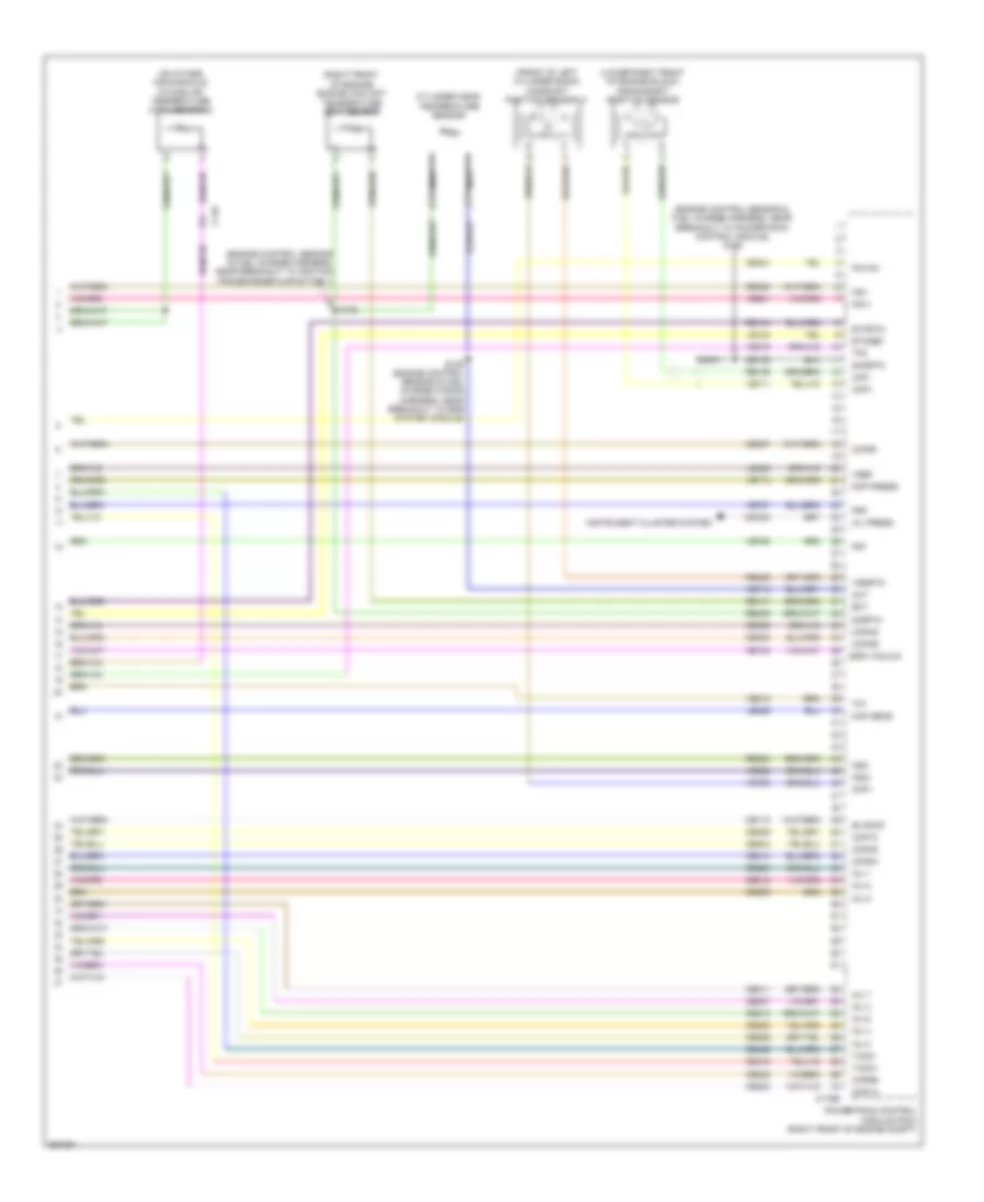 https://portal-diagnostov.com/license.html
Automotive Electricians Portal FZCO
Automotive Electricians Portal FZCO
https://portal-diagnostov.com/license.html
https://portal-diagnostov.com/license.html
Automotive Electricians Portal FZCO
Automotive Electricians Portal FZCOList of elements for 5.8L Supercharged, Engine Performance Wiring Diagram (6 of 6) for Ford Mustang GT 2013:
- (engine control sensor & fuel charge harness, near breakout to ignition transformer capacitor 1)
- (engine control sensor & fuel charge harness, near breakout to powertrain control module) s108
- (front of left cylinder bank) camshaft position sensor 11
- (lower right front of engine block) crankshaft position sensor
- (on intake air manifold) intake air temperature (iat2) sensor 2
- (right front of engine) engine coolant temperature (ect) sensor
- C146
- C175e
- Ce113
- Ce133
- Ce205
- Ce206
- Ce207
- Ce208
- Ce209
- Ce210
- Ce211
- Ce212
- Ce303
- Ce304
- Ce305
- Ce306
- Ce307
- Ce308
- Ce309
- Ce310
- Ce321
- Ce412
- Ce426
- Cht
- Ckp+
- Ckp-
- Cmc24
- Cmp1
- Cop1a
- Cop2d
- Cop3b
- Cop4g
- Cop5f
- Cop6e
- Cop7c
- Cop8h
- Cylinder head temperature sensor
- De135
- Diff press
- Ect
- Egr vacuum
- Etcref
- Etcrtn
- Evapcp
- Frp
- Frt
- Inj 1
- Inj 2
- Inj 3
- Inj 4
- Inj 5
- Inj 6
- Inj 7
- Inj 8
- Instrument cluster system
- Ks1+
- Ks1-
- Ks2+
- Ks2-
- Le134
- Le329
- Le423
- Map sens
- Nca
- Oil press
- Pcvhc
- Powertrain control module (pcm) (right front of engine compt)
- Re134
- Re135
- Re141
- Re323
- Re324
- Re405
- Re429
- S102
- S106 (engine control sensor & fuel charge wiring harness, near breakout to egr system module)
- Shdrtn
- Sigrtn
- Tacm+
- Tacm-
- Tp1
- Tp2
- Ve706
- Ve711
- Ve712
- Ve713
- Ve727
- Ve728
- Ve801
- Ve802
- Ve818
- Ve819
- Vref
- Vrsrtn
EXTERIOR LIGHTS
Backup Lamps Wiring Diagram for Ford Mustang GT 2013
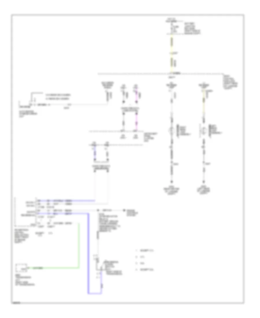 https://portal-diagnostov.com/license.html
Automotive Electricians Portal FZCO
Automotive Electricians Portal FZCO
https://portal-diagnostov.com/license.html
https://portal-diagnostov.com/license.html
Automotive Electricians Portal FZCO
Automotive Electricians Portal FZCOList of elements for Backup Lamps Wiring Diagram for Ford Mustang GT 2013:
- 3.7l
- 5.8l
- 6r80 transmission (a/t) (right side of transmission)
- Auto dimming interior mirror unit
- Battery junction box (bjb) (right side of engine compt)
- Body control module b (right rear of luggage compt)
- C1381b
- C1381t
- C175b
- C175t
- C237
- C4368a
- C919
- Cat03
- Cet47
- Cet60
- Cls10
- Cls11
- Computer data lines system
- E/c mirror reverse signal
- Engine controls system
- Except 3.7l
- Except 5.8l
- Fuse 20a
- G400 (left rear of luggage compt)
- G402 (rear center of luggage compt)
- Hot at all times
- Hs can +
- Hs can -
- Instrument panel cluster (ipc)
- Left rear lamp assembly
- Lt reverse lamp
- Ms can +
- Ms can -
- Nca
- Powertrain control module (pcm) (right front of engine compt)
- Re406
- Reverse
- Reverse sw
- Reversing
- Reversing lamps switch (m/t) (right side of transmission)
- Right rear lamp assembly
- Rt reverse lamp
- S404
- S407
- Sbb18
- Sig rtn
- Tr-p
- Vbatt
- Vdb04
- Vdb05
- Vdb06
- Vdb07
- W/ rearview camera
- W/o rearview camera
Exterior Lamps Wiring Diagram (1 of 3) for Ford Mustang GT 2013
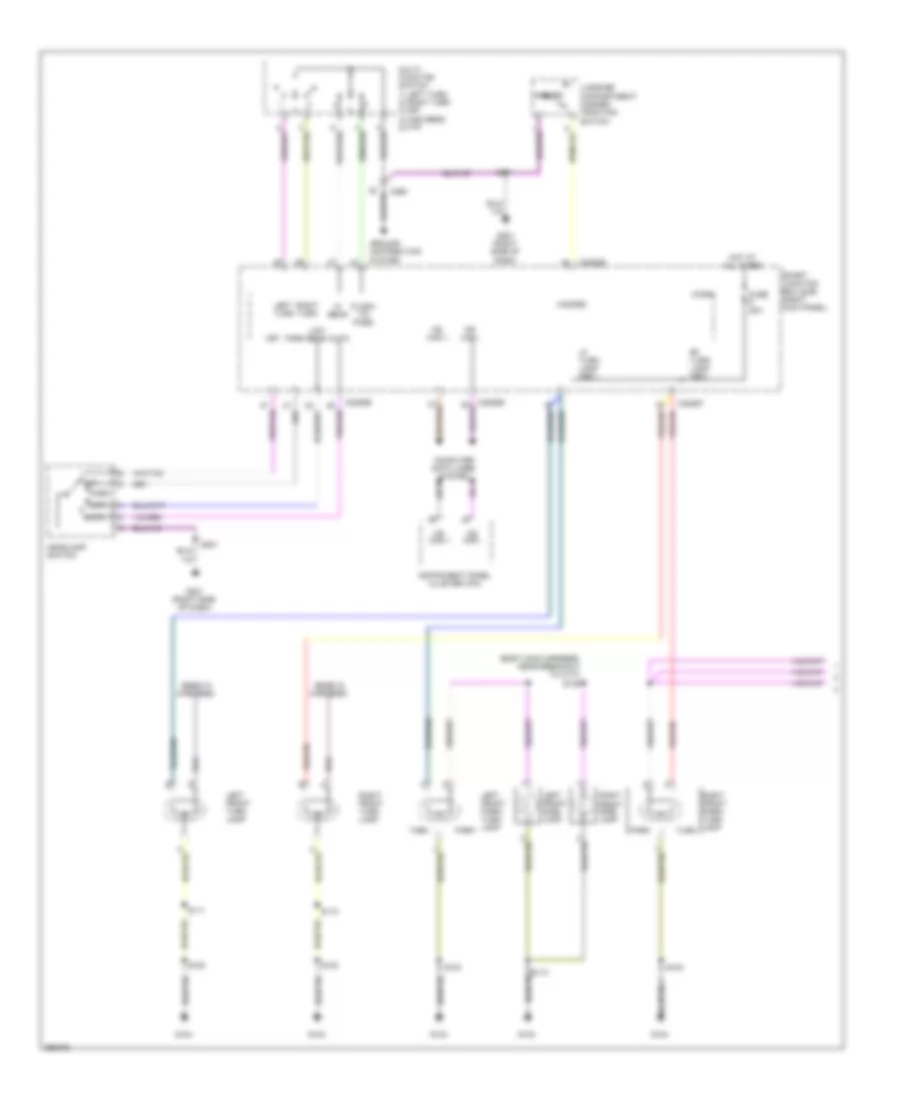 https://portal-diagnostov.com/license.html
Automotive Electricians Portal FZCO
Automotive Electricians Portal FZCO
https://portal-diagnostov.com/license.html
https://portal-diagnostov.com/license.html
Automotive Electricians Portal FZCO
Automotive Electricians Portal FZCOList of elements for Exterior Lamps Wiring Diagram (1 of 3) for Ford Mustang GT 2013:
- (body main harness, near breakout to c177) s128
- (ends in harness)
- All times
- Auto
- C2280b
- C2280f
- C260
- Computer data lines system
- Flash- to- pass
- Fuse 20a
- G104
- G201 (right side of dash)
- Ground distribution system
- Hazard
- Headlamp switch
- Hi beam
- Hot at
- Instrument panel cluster (ipc)
- Left front park/ turn lamp
- Left front side lamp
- Left front turn lamp
- Left turn
- Lf turn lamp (fet)
- Low
- Low beam
- Luggage compartment/ hazard/ traction switch
- Micro
- Ms can +
- Ms can -
- Multi- function switch 1) left turn 2) right turn 3) off 4) high beam 5) ftp
- Off
- Park
- Rf turn lamp (fet)
- Right front park/ turn lamp
- Right front side lamp
- Right front turn lamp
- Right turn
- S100
- S110
- S111
- S201
- Smart junction box (sjb) (right kick panel)
- Turn
Exterior Lamps Wiring Diagram (2 of 3) for Ford Mustang GT 2013
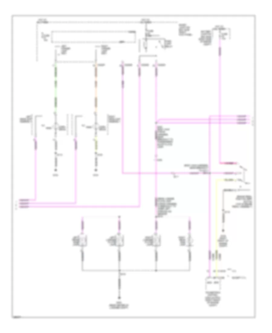 https://portal-diagnostov.com/license.html
Automotive Electricians Portal FZCO
Automotive Electricians Portal FZCO
https://portal-diagnostov.com/license.html
https://portal-diagnostov.com/license.html
Automotive Electricians Portal FZCO
Automotive Electricians Portal FZCOList of elements for Exterior Lamps Wiring Diagram (2 of 3) for Ford Mustang GT 2013:
- (body main harness, near breakout to c211) s213
- (rear license plate lamp wiring harness, in breakout to inner left parking aid sensor) s418
- 3.7l
- Battery junction box (bjb) (right side of engine compt)
- Boo
- Bpp
- Bps
- Brake pedal position (bpp) switch (top of brake pedal assembly)
- C1381b
- C175b
- C211
- C405
- Ccb08
- Ce509
- Clf06
- Clf07
- Corn- ering
- Except 3.7l
- Fuse 10a
- Fuse 15a
- G100
- G102 (right front of engine compt)
- G104
- G402 (rear center of luggage compt)
- Hot at all times
- Left corner lamp (fet)
- Left headlamp assembly
- Left license plate lamp
- Left rear side lamp
- Micro
- Park
- Park lamp relay
- Powertrain control module (pcm) (right front of engine compt)
- Right corner lamp (fet)
- Right headlamp assembly
- Right license plate lamp
- Right rear side lamp
- S100
- S112
- S115
- S419
- Smart junction box (sjb) (right kick panel)
Exterior Lamps Wiring Diagram (3 of 3) for Ford Mustang GT 2013
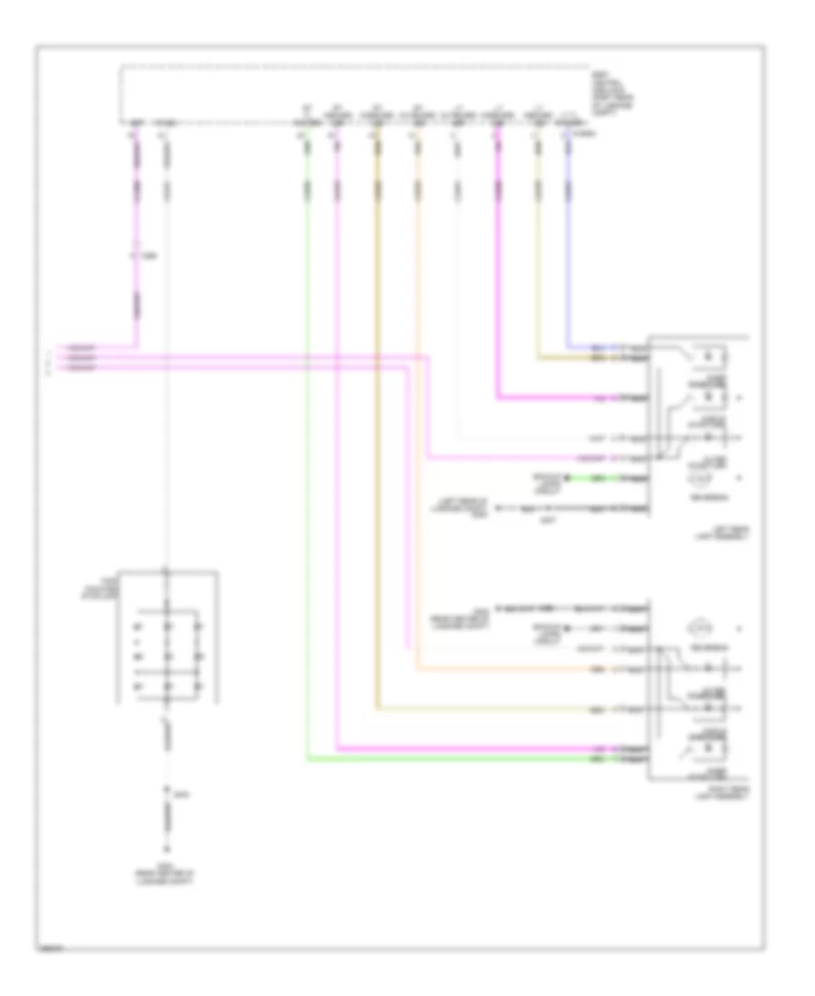 https://portal-diagnostov.com/license.html
Automotive Electricians Portal FZCO
Automotive Electricians Portal FZCO
https://portal-diagnostov.com/license.html
https://portal-diagnostov.com/license.html
Automotive Electricians Portal FZCO
Automotive Electricians Portal FZCOList of elements for Exterior Lamps Wiring Diagram (3 of 3) for Ford Mustang GT 2013:
- (left rear of luggage compt) g400
- Backup lamps circuit
- Body control module b (right rear of luggage compt)
- Bpp
- C265
- Ccb08
- Chmsl
- Cls17
- Cls18
- Cls19
- Cls50
- Cls51
- Cls52
- Cls53
- Cls54
- Cls55
- G402 (rear center of luggage compt)
- High mounted stoplamp
- Inner stop/turn
- Left rear lamp assembly
- Lt inboard led
- Lt midboard led
- Lt outboard led
- Lt tl outage
- Middle stop/turn
- Nca
- Outer stop/turn
- Reversing
- Right rear lamp assembly
- Rt inboard led
- Rt midboard led
- Rt outboard led
- Rt tl outage
- S404
- S407
GROUND DISTRIBUTION
Ground Distribution Wiring Diagram (1 of 4) for Ford Mustang GT 2013
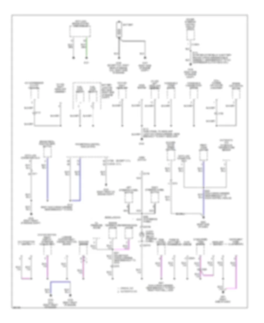 https://portal-diagnostov.com/license.html
Automotive Electricians Portal FZCO
Automotive Electricians Portal FZCO
https://portal-diagnostov.com/license.html
https://portal-diagnostov.com/license.html
Automotive Electricians Portal FZCO
Automotive Electricians Portal FZCOList of elements for Ground Distribution Wiring Diagram (1 of 4) for Ford Mustang GT 2013:
- (3.7l)
- (5.8l) charge air cooler (cac) pump
- (automatic a/c) in-vehicle temperature sensor
- (b0ss laguna)
- (except 3.7l)
- (if equipped) video camera
- (w/ hid) left headlamp assembly
- (w/ hid) right headlamp assembly
- (w/o hid) right headlamp
- (w/o navigation) front display interface module (fdim)
- A/c compressor clutch field coil
- Anti-lock brake system (abs) module
- Automatic a/c
- Battery
- Battery junction box (bjb) (right side of engine compt)
- Blower motor speed control
- Brake pedal position (bpp) switch
- Breakout to right headlamp)
- C110
- C1381b
- C1463a
- C175b
- C192
- C211
- C212
- C217b
- C2274a
- C2274b
- C260
- C275
- C294a
- Clock- spring (below steering wheel)
- Data link connector (dlc)
- Engine cooling fan motor
- Engine temperature gauge
- Front cigar lighter
- Fuel pump relay
- Fuel pump relay 2
- G100
- G101
- G102 (right front of engine compt)
- G103 (right front of engine compt)
- G105 (right side of engine compt)
- G106 (except 5.8l: right rear of engine) (5.8l: right side of engine)
- G107 (right side of engine compt)
- G108 (5.0l) (right front of engine)
- G109 (right front of engine)
- G200 (right side of dash)
- G201 (right side of dash)
- Headlamp switch
- Hood switch
- Horn switch
- Hvac module
- Instrument panel cluster (ipc)
- Left steering wheel switch
- Luggage compartment/ hazard/traction switch
- Manual a/c
- Multifunction switch
- Nca
- Oil pressure gauge
- Passive anti-theft transceiver
- Performance gauge
- Power steering control module (pscm)
- Powertrain control module (pcm)
- Ride control switch
- Right steering wheel switch
- S115 (body main wiring harness, near breakout to g102)
- S118 (starter motor relay & battery ground wiring harness/cable assembly, near breakout to a/c compressor clutch field coil)
- S201 (main wiring harness, near breakout to right front footwell lamp)
- S298 (in steering nca
- Sunload sensor
- Wheel)
- Windshield washer pump motor
- Windshield wiper motor
- Wiring harness, near breakout to c275)
Ground Distribution Wiring Diagram (2 of 4) for Ford Mustang GT 2013
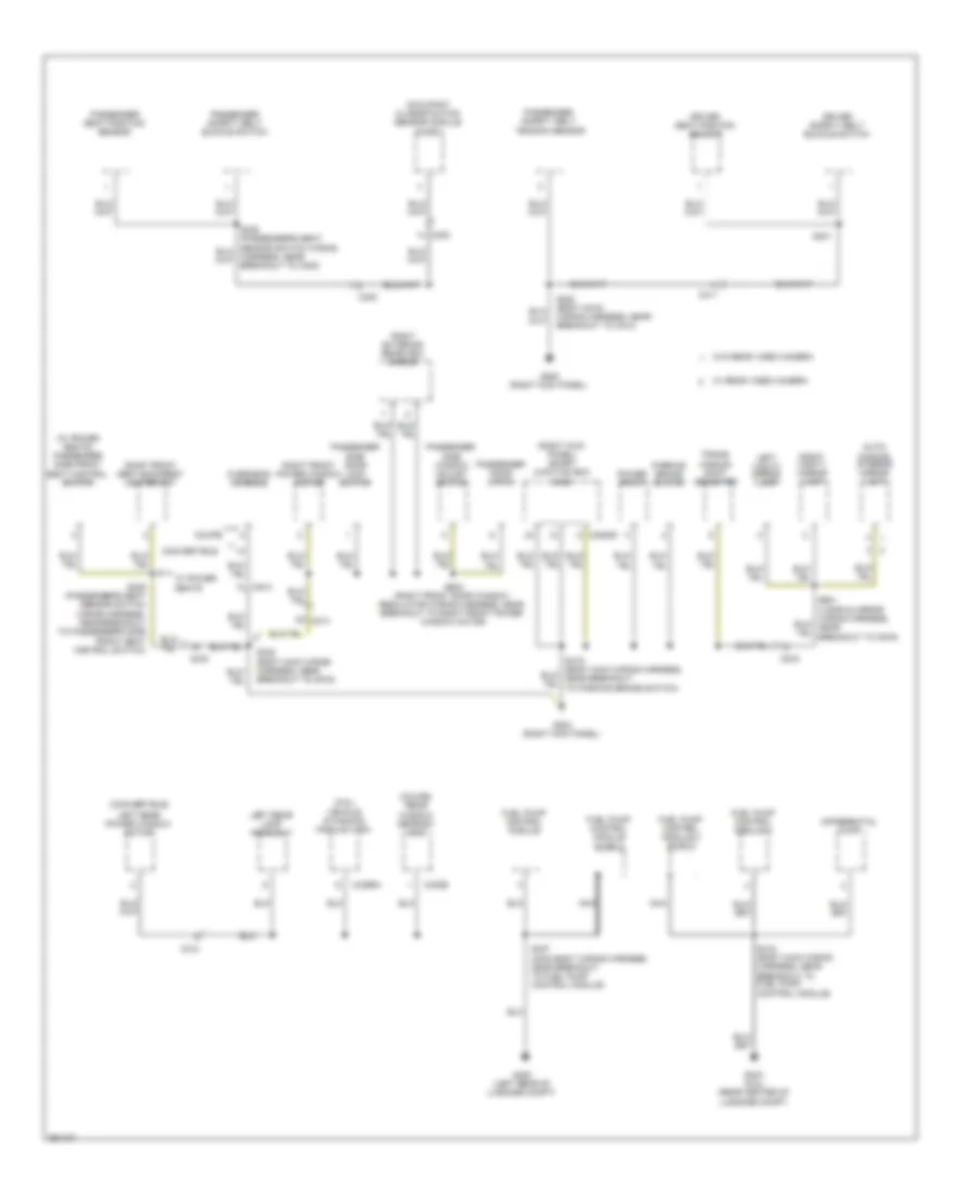 https://portal-diagnostov.com/license.html
Automotive Electricians Portal FZCO
Automotive Electricians Portal FZCO
https://portal-diagnostov.com/license.html
https://portal-diagnostov.com/license.html
Automotive Electricians Portal FZCO
Automotive Electricians Portal FZCOList of elements for Ground Distribution Wiring Diagram (2 of 4) for Ford Mustang GT 2013:
- (5.8l) vehicle dynamics module (vdm)
- (convertible)
- (coupe) rear window defrost grid
- (right kick panel) smart junction box (sjb)
- (w/ power seats) passenger side front seat control switch
- Auto- dimming interior mirror unit
- C2280d
- C300
- C311
- C312
- C402b
- C4396a
- C913
- C919
- Convertible
- Coupe
- D3 c213
- Differential pump
- Driver safety belt buckle switch
- Driver seat position sensor
- Fuel pump control module
- Fuel pump control module 2
- Fuel pump control module 2 shield
- Fuel pump control module shield
- G203 (right kick panel)
- G205 (right kick panel)
- G400 (left rear of luggage compt)
- G403 (5.8l) (rear center of luggage compt)
- Left rear lamp assembly
- Left rear power window motor
- Left vanity mirror lamp
- Nca
- Occupant classification sensor module (ocsm)
- Overhead console
- Parking brake switch
- Passenger door latch
- Passenger safety belt
- Passenger safety belt buckle switch
- Passenger seat position sensor
- Passenger side door lock switch
- Passenger side window adjust switch
- Power point
- Right exterior rearview mirror
- Right front power window motor
- Right front seat backrest heater mat
- Right vanity mirror lamp
- S220 (body maiin wiring harness, near breakout to c210)
- S301
- S306 (passenger's seat sensor switch wiring harness, near breakout to passenger's side front seat control switch)
- S328 (body main wiring harness, near breakout to c919)
- S407 (main body wiring harness, near breakout to fuel pump control module)
- S415 (body main wiring harness, near breakout to fuel pump control module)
- S602 (right front door window regulator wiring harness, near breakout to right front power window motor)
- Tension sensor
- Trans- mission shift selector
- W/ power seats
- W/ rear video camera
- W/o rear video camera
Ground Distribution Wiring Diagram (3 of 4) for Ford Mustang GT 2013
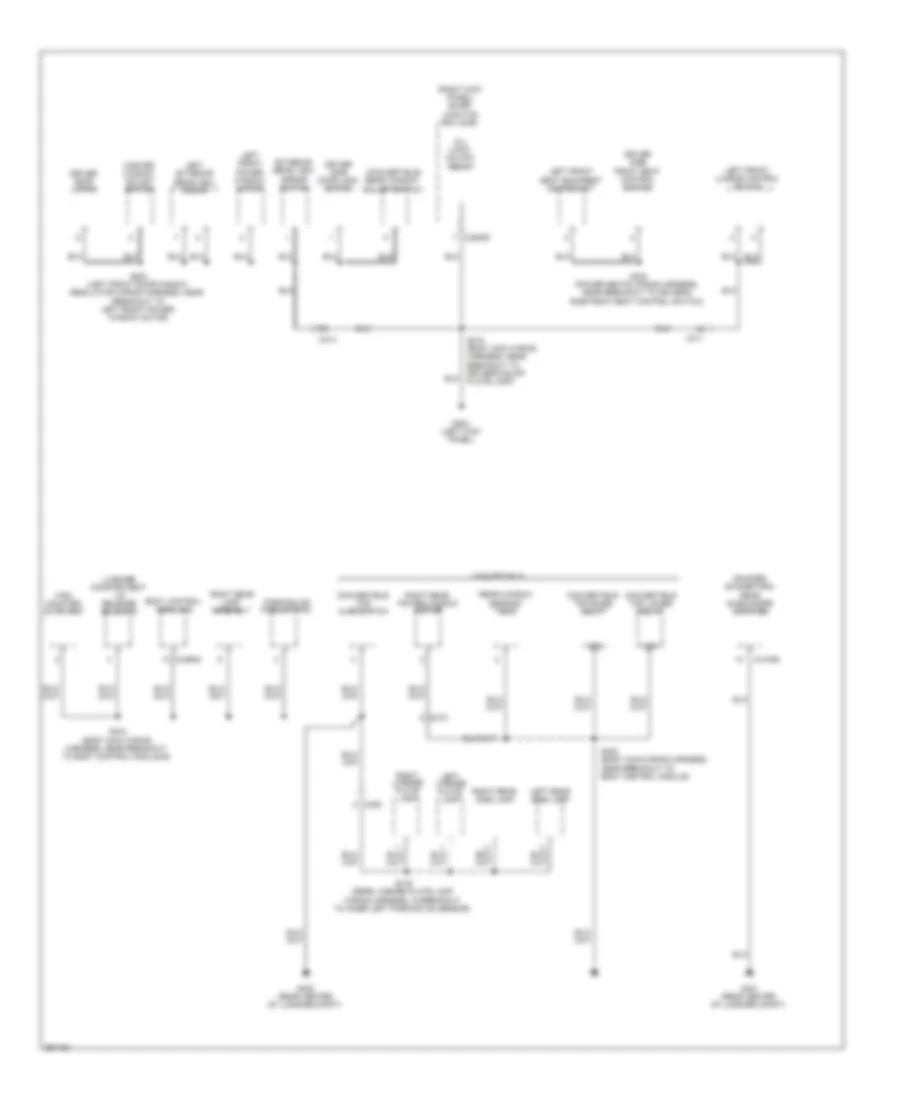 https://portal-diagnostov.com/license.html
Automotive Electricians Portal FZCO
Automotive Electricians Portal FZCO
https://portal-diagnostov.com/license.html
https://portal-diagnostov.com/license.html
Automotive Electricians Portal FZCO
Automotive Electricians Portal FZCOList of elements for Ground Distribution Wiring Diagram (3 of 4) for Ford Mustang GT 2013:
- (convertible) rear window adjust switch
- (right kick panel) smart junction box (sjb)
- (shaker/ shaker pro) rear subwoofer amplifier
- 87a
- All lock/ unlock relay
- Body control module b
- C214
- C2280d
- C311
- C313
- C405
- C4109a
- C4368a
- Convertible
- Convertible top ajar switch
- Convertible top lower relay
- Convertible top raise relay
- Driver door latch
- Driver side door lock switch
- Driver side front seat control switch
- Exterior rear view mirror switch
- G204 (left kick panel)
- G401 (rear center of luggage compt)
- G402 (rear center of luggage compt)
- High mounted stoplamp
- Left exterior rear view mirror
- Left front lumbar control switch
- Left front power window motor
- Left front seat backrest heater mat
- Left license plate lamp
- Left rear side lamp
- Luggage compartment lid release solenoid
- Master window adjust switch
- Parking aid module (pam)
- Rear window defrost grid
- Right license plate lamp
- Right rear lamp assembly
- Right rear power window motor
- Right rear side lamp
- S215 (body main wiring harness, near breakout to driver's scuff plate lamp)
- S303 (power seats wiring harness, near breakout to driver's side front seat control switch)
- S400 (body main wiring harness, near breakout to body control module)
- S404 (body main wiring harness, near breakout to body control module b)
- S419 (rear license plate lamp wiring harness, in breakout to inner left parking aid sensor)
- S503 (left front door window regulator wiring harness, near breakout to left front power window motor)
Ground Distribution Wiring Diagram (4 of 4) for Ford Mustang GT 2013
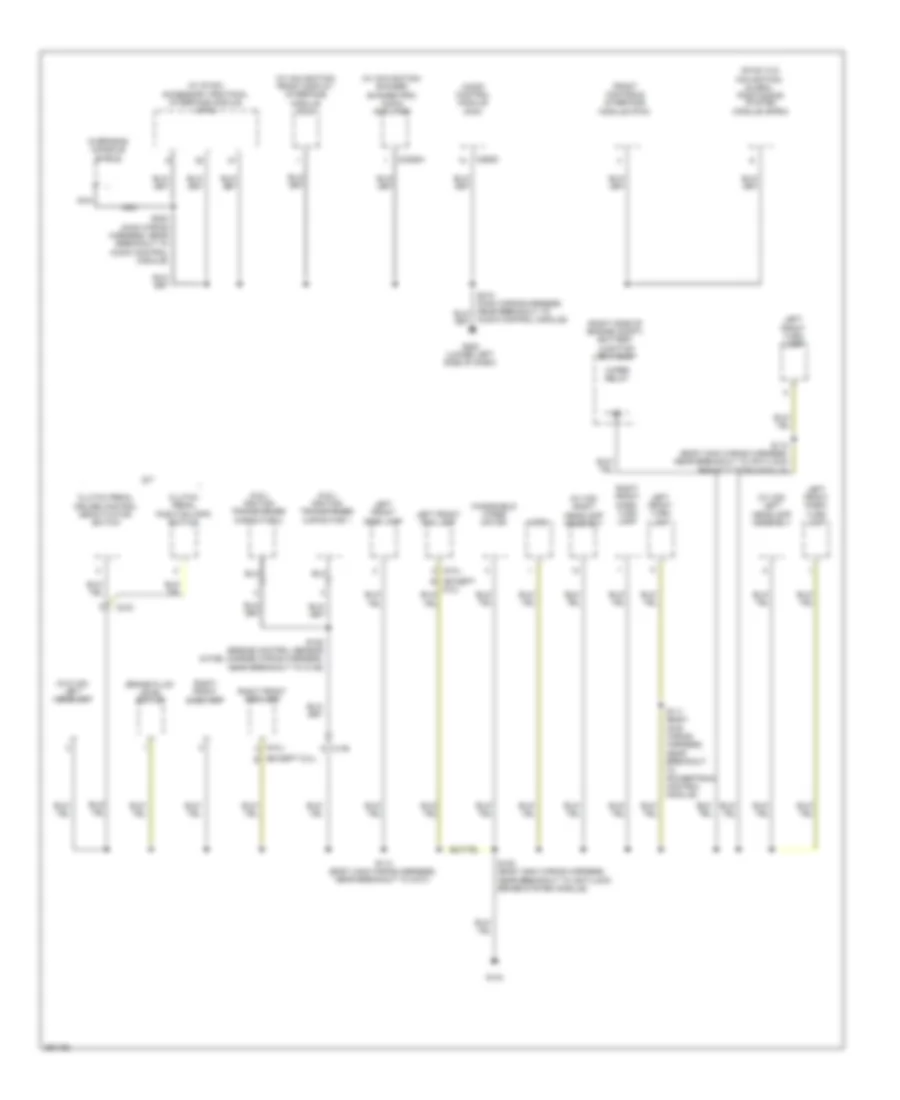 https://portal-diagnostov.com/license.html
Automotive Electricians Portal FZCO
Automotive Electricians Portal FZCO
https://portal-diagnostov.com/license.html
https://portal-diagnostov.com/license.html
Automotive Electricians Portal FZCO
Automotive Electricians Portal FZCOList of elements for Ground Distribution Wiring Diagram (4 of 4) for Ford Mustang GT 2013:
- (5.0l)
- (5.8l) ignition transformer capacitor 1
- (5.8l) ignition transformer capacitor 2
- (except 5.0l) b
- (except b
- (right side of engine compt) battery junction box (bjb)
- (sync w/o
- (w/ hid) left headlamp assembly
- (w/ hid) right headlamp assembly
- (w/ navigation) front display interface module (fdim)
- (w/ navigation/ shaker/ shaker pro) audio amplifier
- (w/ sync) accessory protocol interface module (apim)
- (w/o hid) left headlamp
- Audio control module (acm)
- Audio control module)
- Brake fluid level switch
- C146
- C215
- C2385a
- C290d
- Clutch pedal cruise control deactivator switch
- Clutch pedal position (cpp) switch
- Front controls interface module (fcim)
- G104
- G202 (lower left side of dash)
- Horn
- Left front fog lamp
- Left front park/ turn lamp
- Left front side lamp
- Left front turn lamp
- M/t
- Navigation) global positioning system module (gpsm)
- Nca
- Overhead console shield
- Right front fog lamp
- Right front park/ turn lamp
- Right front side lamp
- S100 (body main wiring harness, near breakout to anti-lock brake system module)
- S105 (engine control sensor & fuel charge wiring harness, near breakout to c146)
- S110 (body main wiring harness, near breakout to anti-lock brake system module)
- S111 (body main wiring harness, near breakout
- S113 (body main wiring harness, near breakout to g101)
- S222 (main wiring harness, near breakout to audio control module)
- To powertrain control module)
- Windshield wiper motor
- Wiper relay
HEADLIGHTS
Headlights Wiring Diagram, with High Intensity Gas Discharge Headlights (1 of 2) for Ford Mustang GT 2013
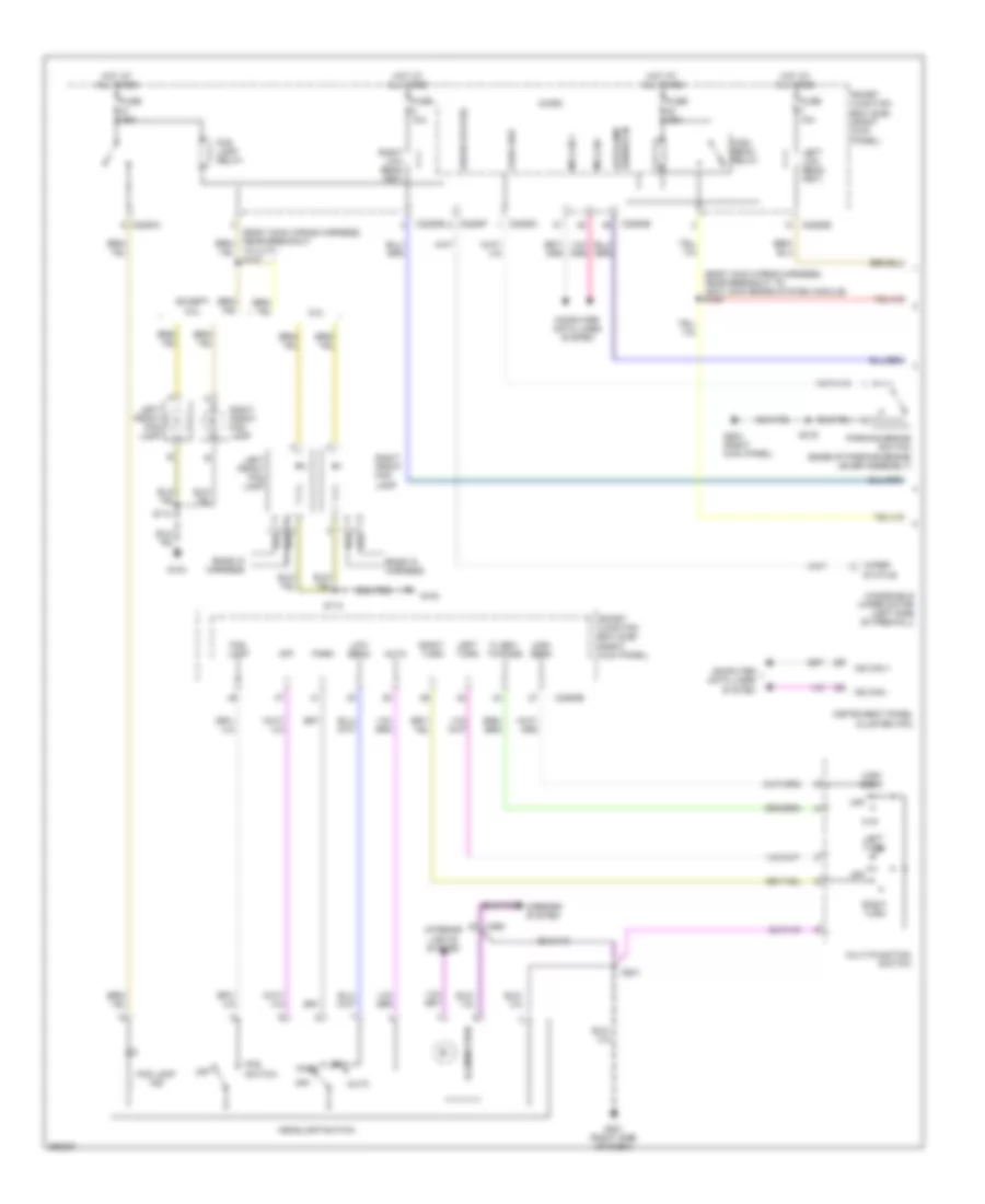 https://portal-diagnostov.com/license.html
Automotive Electricians Portal FZCO
Automotive Electricians Portal FZCO
https://portal-diagnostov.com/license.html
https://portal-diagnostov.com/license.html
Automotive Electricians Portal FZCO
Automotive Electricians Portal FZCOList of elements for Headlights Wiring Diagram, with High Intensity Gas Discharge Headlights (1 of 2) for Ford Mustang GT 2013:
- (body main wiring harness, near breakout to anti-lock brake system module) s129
- 5.0l
- Auto
- Autolamp sensor in
- C2280a
- C2280b
- C2280c
- C2280e
- C2280f
- C260
- Computer data lines system
- Ends in harness
- Except
- Flash- to-pass
- Fog lamp
- Fog lamp ind
- Fog lamp relay
- Fog switch
- Ftp
- Fuse 10a
- Fuse 15a
- G104
- G201 (right side of dash)
- G203 (right kick panel)
- Headlamp switch
- High beam
- High beam relay
- Hot at all times
- Illumination
- Instrument panel cluster (ipc)
- Interior lights system
- Left front fog lamp
- Left low beam (fet)
- Left turn
- Low
- Low beam
- Micro
- Mirrors system
- Ms can +
- Ms can -
- Multi-function switch
- Off
- Park
- Park brk
- Parking brake switch (base of parking brake lever assembly)
- Right front fog lamp
- Right low beam (fet)
- Right turn
- S113
- S201
- S319
- Smart junction box (sjb) (right kick panel)
- Status
- To c177) s127
- Windshield wiper motor (left side of firewall)
- Wiper
- Wiper status
Headlights Wiring Diagram, with High Intensity Gas Discharge Headlights (2 of 2) for Ford Mustang GT 2013
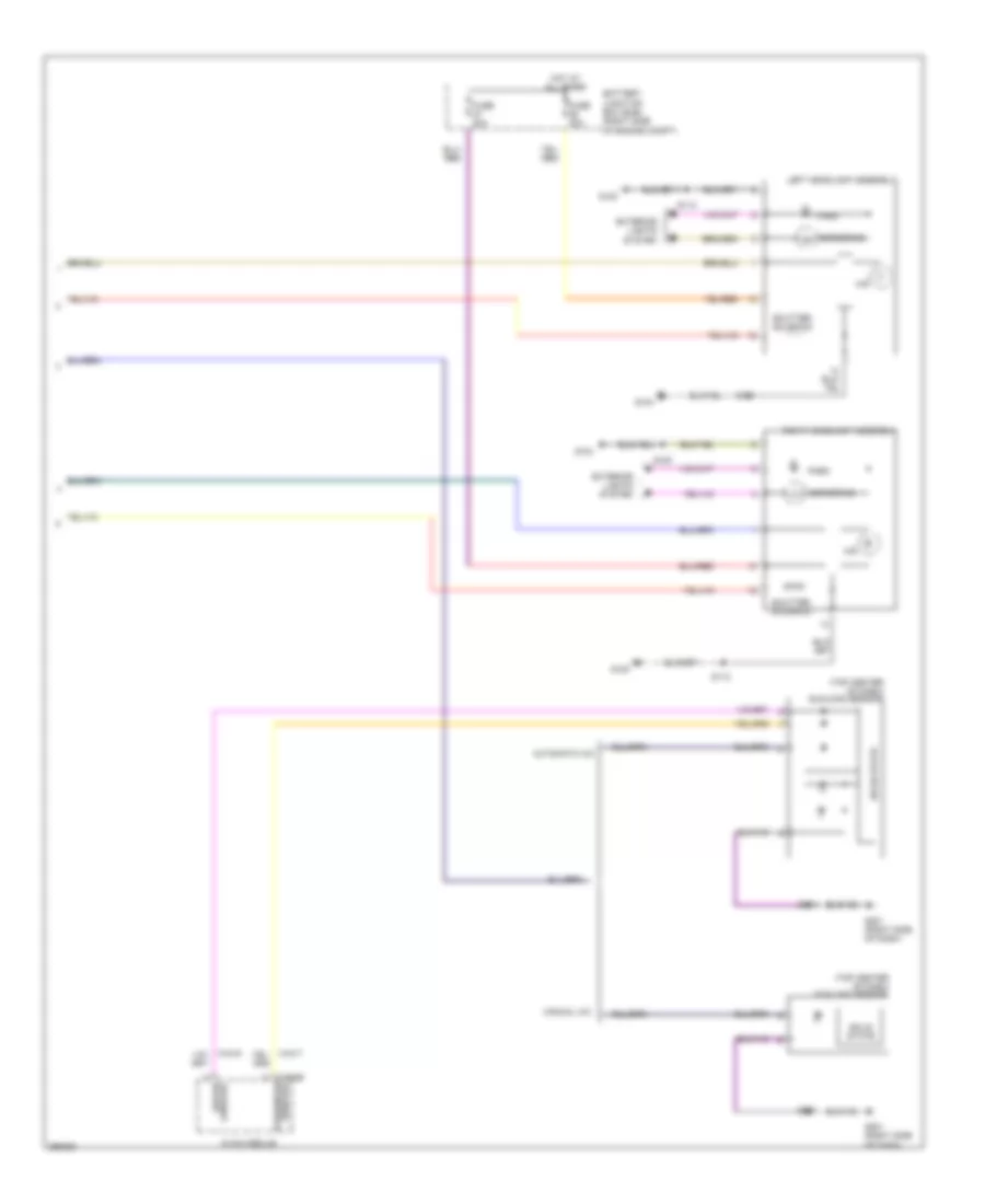 https://portal-diagnostov.com/license.html
Automotive Electricians Portal FZCO
Automotive Electricians Portal FZCO
https://portal-diagnostov.com/license.html
https://portal-diagnostov.com/license.html
Automotive Electricians Portal FZCO
Automotive Electricians Portal FZCOList of elements for Headlights Wiring Diagram, with High Intensity Gas Discharge Headlights (2 of 2) for Ford Mustang GT 2013:
- (top center of dash)
- Automatic a/c
- Battery junction box (bjb) (right side of engine compt)
- C294b
- Cornering
- Driver
- Exterior lights system
- Fuse 20a
- G100
- G104
- G201 (right side of dash)
- Hid
- Hot at all times
- Left headlamp assembly
- Manual a/c
- Park
- Passenger hvac module
- Right headlamp assembly
- S100
- S112
- S201
- Shutter solenoid
- Solid state
- Sunload
- Sunload sensor
Headlights Wiring Diagram, without High Intensity Gas Discharge Headlights (1 of 2) for Ford Mustang GT 2013
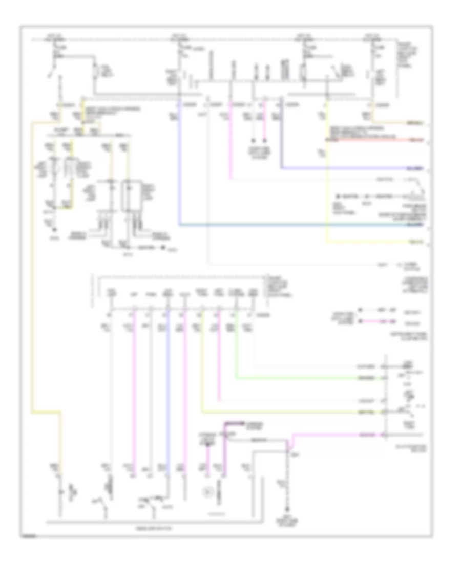 https://portal-diagnostov.com/license.html
Automotive Electricians Portal FZCO
Automotive Electricians Portal FZCO
https://portal-diagnostov.com/license.html
https://portal-diagnostov.com/license.html
Automotive Electricians Portal FZCO
Automotive Electricians Portal FZCOList of elements for Headlights Wiring Diagram, without High Intensity Gas Discharge Headlights (1 of 2) for Ford Mustang GT 2013:
- (body main wiring harness, near breakout to anti-lock brake system module) s129
- 5.0l
- Auto
- Autolamp sensor in
- C2280a
- C2280b
- C2280c
- C2280e
- C2280f
- C260
- Computer data lines system
- Ends in harness
- Except
- Flash- to-pass
- Fog lamp
- Fog lamp relay
- Ftp
- Fuse 10a
- Fuse 15a
- G104
- G201 (right side of dash)
- G203 (right kick panel)
- Headlamp switch
- High beam
- High beam relay
- Hot at all times
- Illumination
- Ind fog lamp
- Instrument panel cluster (ipc)
- Interior lights system
- Left front fog lamp
- Left low beam (fet)
- Left turn
- Low
- Low beam
- Micro
- Mirrors system
- Ms can +
- Ms can -
- Multi-function switch
- Off
- Park
- Park brake switch (base of parking brake lever assembly)
- Park brk
- Right front fog lamp
- Right low beam (fet)
- Right turn
- S113
- S201
- S319
- Smart junction box (sjb) (right kick panel)
- Status
- Switch fog
- To c177) s127
- Windshield wiper motor (left side of firewall)
- Wiper
- Wiper status
Headlights Wiring Diagram, without High Intensity Gas Discharge Headlights (2 of 2) for Ford Mustang GT 2013
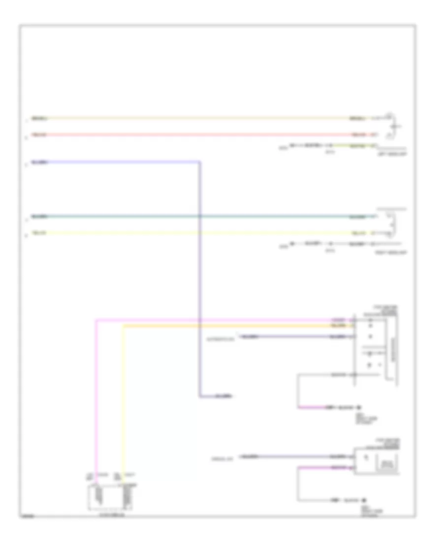 https://portal-diagnostov.com/license.html
Automotive Electricians Portal FZCO
Automotive Electricians Portal FZCO
https://portal-diagnostov.com/license.html
https://portal-diagnostov.com/license.html
Automotive Electricians Portal FZCO
Automotive Electricians Portal FZCOList of elements for Headlights Wiring Diagram, without High Intensity Gas Discharge Headlights (2 of 2) for Ford Mustang GT 2013:
- (top center of dash)
- Automatic a/c
- C294b
- Driver
- G100
- G104
- G201 (right side of dash)
- Left headlamp
- Manual a/c
- Passenger hvac module
- Right headlamp
- S112
- S113
- S201
- Solid state
- Sunload
- Sunload sensor
HORN
Horn Wiring Diagram for Ford Mustang GT 2013
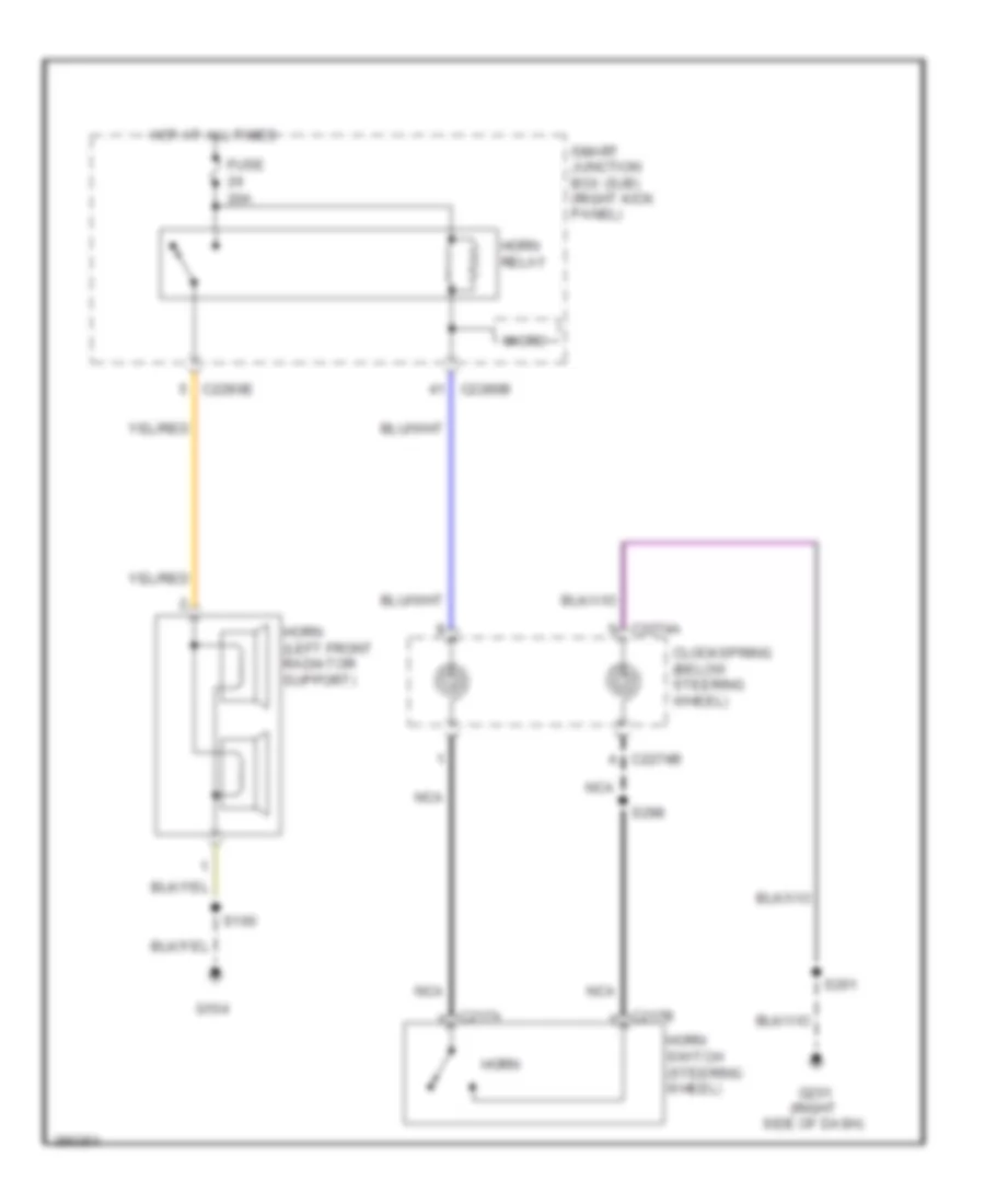 https://portal-diagnostov.com/license.html
Automotive Electricians Portal FZCO
Automotive Electricians Portal FZCO
https://portal-diagnostov.com/license.html
https://portal-diagnostov.com/license.html
Automotive Electricians Portal FZCO
Automotive Electricians Portal FZCOList of elements for Horn Wiring Diagram for Ford Mustang GT 2013:
- 20a
- C217a
- C217b
- C2274a
- C2274b
- C2280b
- C2280e
- Clockspring (below steering wheel)
- Fuse
- G104
- G201 (right side of dash)
- Horn
- Horn (left front radiator support)
- Horn relay
- Horn switch (steering wheel)
- Hot at all times
- Micro
- Nca
- S100
- S201
- S298
- Smart junction box (sjb) (right kick panel)
INSTRUMENT CLUSTER
Instrument Cluster Wiring Diagram (1 of 2) for Ford Mustang GT 2013
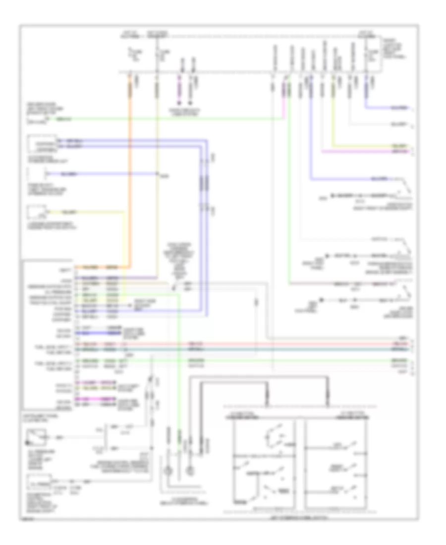 https://portal-diagnostov.com/license.html
Automotive Electricians Portal FZCO
Automotive Electricians Portal FZCO
https://portal-diagnostov.com/license.html
https://portal-diagnostov.com/license.html
Automotive Electricians Portal FZCO
Automotive Electricians Portal FZCOList of elements for Instrument Cluster Wiring Diagram (1 of 2) for Ford Mustang GT 2013:
- (3.7l)
- (5.8l)
- (driver's door) left front power window motor
- (main wiring harness, near breakout to left front footwell lamp) (boss laguna) s214
- (right side of dash) g201
- 3.7l & 5.0l
- 5.8l
- Anti-theft
- Anti-theft system
- Auto-dimming interior mirror unit
- Brake fluid sw
- Brake fluid sw rtn
- C110
- C1381e
- C146
- C175e
- C210
- C211
- C214
- C2274a
- C2280a
- C2280b
- C2280c
- C2280f
- C260
- C919
- Cbp36
- Cc2274b
- Cca15
- Clockspring (below steering wheel)
- Cmc24
- Cmc29
- Compass+
- Compass-
- Computer data lines system
- Down
- Dr ajar
- Driver door latch (driver's door)
- Fuel level input 1
- Fuel level input 2
- Fuel return
- Fuse 10a
- Fuse 20a
- Fuse 5a
- G100
- G203 (right kick panel)
- G204 (left kick panel)
- Gd116
- Hood switch (right front of engine compt)
- Hot at all times
- Hot in run or start
- Hs can+
- Hs can-
- Info
- Instrument panel cluster (ipc)
- Ivd
- Key in ignition
- Left
- Left steering wheel switch
- Lf door ajar
- Luggage compartment/ hazard/traction switch
- Message cntr sw rtn
- Message cntr sw sig
- Ms can+
- Ms can-
- Nca
- Oil press
- Oil pressure
- Oil pressure switch (lower left side of engine)
- Park brake
- Parking brake switch (base of parking brake lever assembly)
- Passive anti- theft transceiver (steering column)
- Pats rx
- Pats tx
- Powertrain control module (pcm) (right front of engine compt)
- Pwr gnd
- Reset
- Rf door ajar
- Right
- Rmc27
- Rmc32
- Rmc33
- S112
- S137 (3.7l) (engine control sensor & fuel charge wiring harness, near breakout to c146)
- S236
- S319
- S503
- Sbp26
- Setup
- Smart junction box (sjb) (right kick panel)
- Traction ctrl on/off
- Vbatt
- Vdb04
- Vdb05
- Vdb06
- Vdb07
- Vmc11
- Vmc23
- Vmc30
- Vmc31
- Vpwr
- Vrt23
- Vrt24
- W/ 3-button message center
- W/ 5-button message center
Instrument Cluster Wiring Diagram (2 of 2) for Ford Mustang GT 2013
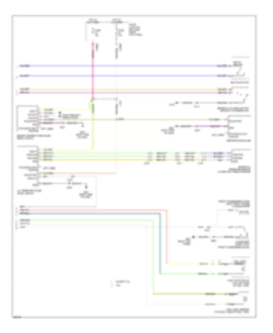 https://portal-diagnostov.com/license.html
Automotive Electricians Portal FZCO
Automotive Electricians Portal FZCO
https://portal-diagnostov.com/license.html
https://portal-diagnostov.com/license.html
Automotive Electricians Portal FZCO
Automotive Electricians Portal FZCOList of elements for Instrument Cluster Wiring Diagram (2 of 2) for Ford Mustang GT 2013:
- (front passenger's door) right front power window motor
- (not used)
- 5.8l
- Brake fluid level switch (brake fluid reservoir)
- C146
- C211
- C213
- C2280a
- C2280b
- C275
- Computer data lines system
- Dr ajar
- Engine oil pressure sensor (lower left side of engine)
- Engine temperature gauge (boss laguna)
- Except 5.8l
- Fuel level sender 1
- Fuel level sensor (top right side of fuel tank)
- Fuel pump module (top left side of fuel tank)
- Fuse 10a
- Fuse 15a
- G104
- G201 (right side of dash)
- G203 (right kick panel)
- Gnd
- Hot at all times
- Hs can+
- Hs can-
- Ignition switch
- Key-in ignition
- Nca
- Oil pressure gauge (boss laguna)
- Ops
- Ops gnd
- Ops out
- Ops pwr
- Passenger door latch (front passenger's door)
- Performance gauge
- Pwm backlight dimming
- Run/start
- S113
- S225
- S227
- S602
- Smart junction box (sjb) (right kick panel)
- Vbatt
Overhead Console Wiring Diagram, Convertible for Ford Mustang GT 2013
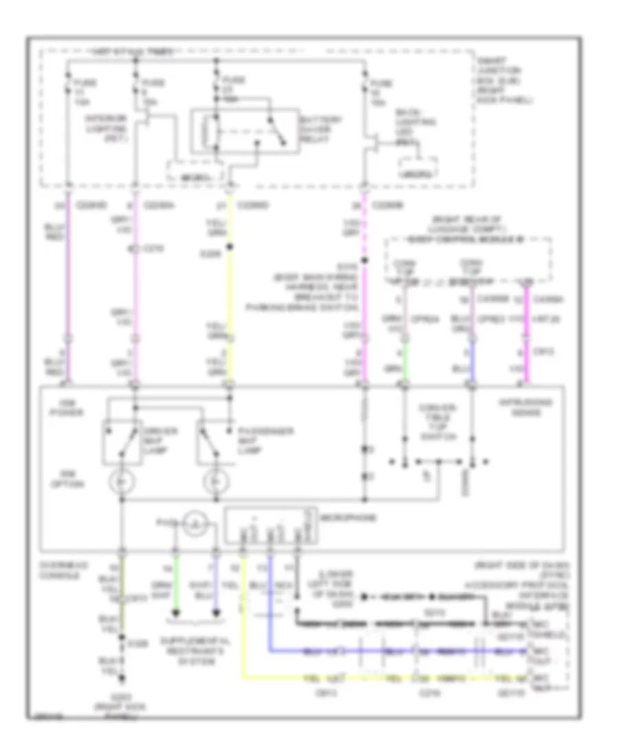 https://portal-diagnostov.com/license.html
Automotive Electricians Portal FZCO
Automotive Electricians Portal FZCO
https://portal-diagnostov.com/license.html
https://portal-diagnostov.com/license.html
Automotive Electricians Portal FZCO
Automotive Electricians Portal FZCOList of elements for Overhead Console Wiring Diagram, Convertible for Ford Mustang GT 2013:
- (lower left side of dash) g202
- (right rear of luggage compt) body control module b
- (right side of dash) (sync) accessory protocol interface module (apim)
- Back- lighting led (fet)
- Battery saver relay
- C210
- C2280a
- C2280b
- C2280d
- C4368a
- C4368b
- C913
- Conv top down sw
- Conv top up sw
- Conver- tible top switch
- Cpr23
- Cpr24
- Down
- Driver map lamp
- Fuse 10a
- Fuse 15a
- G203 (right kick panel)
- Hot at all times
- Interior lighting (fet)
- Intrusions sense
- Ism option
- Ism power
- Lin
- Mic
- Micro
- Microphone
- Nca
- Out + gd115
- Out + mic
- Out -
- Out - mic
- Overhead console
- Padi
- Passenger map lamp
- Rmm13
- S209
- S210
- S315 (body main wiring harness, near breakout to parking brake switch)
- S328
- Shield gd115
- Shield mic
- Smart junction box (sjb) (right kick panel)
- Vmm13
- Vrt26
Overhead Console Wiring Diagram, Coupe for Ford Mustang GT 2013
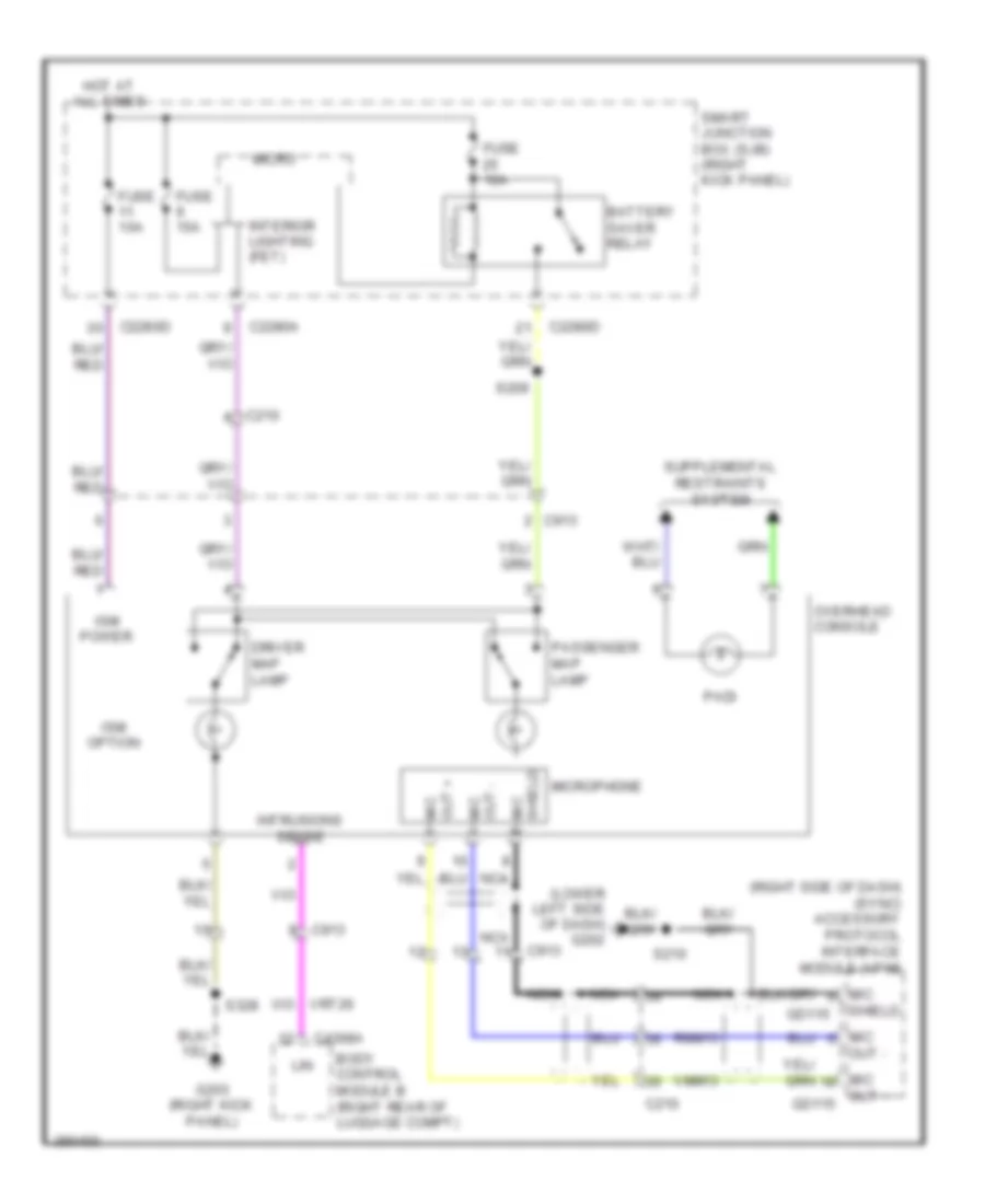 https://portal-diagnostov.com/license.html
Automotive Electricians Portal FZCO
Automotive Electricians Portal FZCO
https://portal-diagnostov.com/license.html
https://portal-diagnostov.com/license.html
Automotive Electricians Portal FZCO
Automotive Electricians Portal FZCOList of elements for Overhead Console Wiring Diagram, Coupe for Ford Mustang GT 2013:
- (lower left side of dash) g202
- (right side of dash) (sync) accessory protocol interface module (apim)
- Battery saver relay
- Body control module b (right rear of luggage compt)
- C210
- C2280a
- C2280d
- C4368a
- C913
- Driver map lamp
- Fuse 10a
- Fuse 15a
- G203 (right kick panel)
- Gd115
- Hot at all times
- Interior lighting (fet)
- Intrusions sense
- Ism option
- Ism power
- Lin
- Mic
- Micro
- Microphone
- Nca
- Out + gd115
- Out + mic
- Out -
- Out - mic
- Overhead console
- Padi
- Passenger map lamp
- Rmm13
- S209
- S210
- S328
- Shield
- Shield mic
- Smart junction box (sjb) (right kick panel)
- Vmm13
INTERIOR LIGHTS
Courtesy Lamps Wiring Diagram (1 of 2) for Ford Mustang GT 2013
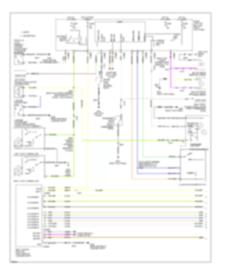 https://portal-diagnostov.com/license.html
Automotive Electricians Portal FZCO
Automotive Electricians Portal FZCO
https://portal-diagnostov.com/license.html
https://portal-diagnostov.com/license.html
Automotive Electricians Portal FZCO
Automotive Electricians Portal FZCOList of elements for Courtesy Lamps Wiring Diagram (1 of 2) for Ford Mustang GT 2013:
- (body main wiring harness, near breakout to c919)
- (left kick panel) g204
- (main wiring harness, near breakout to headlamp switch)
- (rear center of luggage compt)
- (trunk lid latch assembly) luggage compartment lid release solenoid
- Ajar lf door
- Ajar rf door
- Alm zone1-b
- Alm zone1-g
- Alm zone1-r
- Alm zone2-b
- Alm zone2-g
- Alm zone2-r
- Alm zone3-b
- Alm zone3-g
- Alm zone3-r
- Battery saver relay
- Body control module b (right rear of luggage compt)
- C210
- C213
- C214
- C2280a
- C2280b
- C2280c
- C2280d
- C237
- C4368a
- C4368b
- C913
- C919
- Cbp35
- Cln44
- Cln45
- Cln46
- Cln48
- Cln49
- Cln50
- Cln51
- Cln52
- Cln53
- Computer data lines system
- Convertible
- Coupe
- Dim sw gnd
- Dimmer
- Dimmer sw
- Dome lp
- Door ajar
- Driver door latch (driver's door)
- Driver map light
- Fuse 10a
- Fuse 15a
- Fuse 2a
- G203 (right kick panel)
- G204 (left kick panel)
- G402
- G402 (rear center of luggage compt)
- Gd110
- Gnd
- Hot at all times
- Hot in start or run
- Illumination dimmer switch
- Interior lighting (fet)
- Led ret
- Left exterior rearview mirror
- Left front power window motor (driver's door)
- Left vanity mirror lamp
- Luggage compartment lamp
- Luggage compartment lid release solenoid (trunk lid latch assembly)
- Micro
- Ms can+
- Ms can-
- Off
- Overhead console
- Passenger door latch (front passenger's door)
- Passenger map light
- Puddle lamp (fet)
- Right exterior rearview mirror
- Right front power window motor (front passenger's door)
- Right vanity mirror lamp
- Rln44
- S209 (body main wiring harness, near breakout to smart junction box)
- S243
- S313
- S328
- S404
- S503
- S602
- S901
- S902 (visor & mirror harness, near breakout to c919)
- Sbb18
- Smart junction box (sjb) (right kick panel)
- Trunk ajar
- Vbatt
- Vdb06
- Vdb07
- Vpwr
Courtesy Lamps Wiring Diagram (2 of 2) for Ford Mustang GT 2013
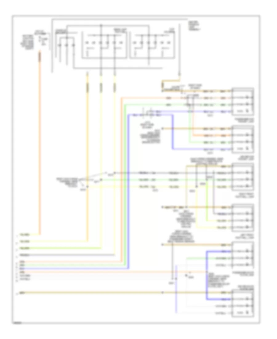 https://portal-diagnostov.com/license.html
Automotive Electricians Portal FZCO
Automotive Electricians Portal FZCO
https://portal-diagnostov.com/license.html
https://portal-diagnostov.com/license.html
Automotive Electricians Portal FZCO
Automotive Electricians Portal FZCOList of elements for Courtesy Lamps Wiring Diagram (2 of 2) for Ford Mustang GT 2013:
- (body main wiring harness near breakout to passenger safety belt tension sensor)
- (body main wiring harness, near breakout to c210)
- (body main wiring harness, near breakout to passenger scuff plate light)
- (main wiring harness, near breakout to restraints control module)
- (right side of dash)
- Battery junction box (bjb) (right side of engine compt)
- C210
- C213
- C214
- Center console lamp assembly
- Console bin lamp
- Coupe convertible
- Cup holders
- Driver map pocket lamp
- Driver scuff plate lamp
- Fuse 20a
- Hot at all times
- J/c 8 (right side of dash)
- J/c 9
- Left front footwell lamp
- Passenger map pocket lamp
- Passenger scuff plate lamp
- Rear lamp footwell
- Right front footwell lamp
- S244
- S245
- S246
- S247 (main wiring harness, near breakout to restraints control module)
- S310 (body main wiring harness, near breakout to parking brake switch)
- S316
- S317
- S318
- S320
- S321
- S322
Instrument Illumination Wiring Diagram for Ford Mustang GT 2013
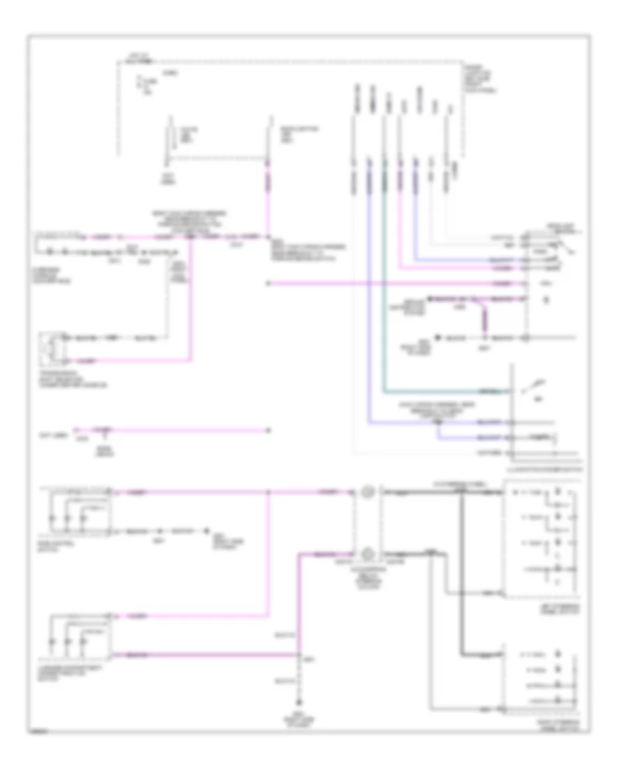 https://portal-diagnostov.com/license.html
Automotive Electricians Portal FZCO
Automotive Electricians Portal FZCO
https://portal-diagnostov.com/license.html
https://portal-diagnostov.com/license.html
Automotive Electricians Portal FZCO
Automotive Electricians Portal FZCOList of elements for Instrument Illumination Wiring Diagram for Ford Mustang GT 2013:
- (body main wiring harness, near breakout to parking brake switch) (convertible) s315
- (in steering wheel) s299
- (main wiring harness, near breakout to head- lamp switch) s243
- (not
- (not used)
- Auto
- Backlighting led (fet)
- Boss laguna
- C210
- C2274a
- C2274b
- C2280b
- C260
- C275
- C913
- Clockspring (below steering column)
- Dim sw gnd
- Dimmer
- Dimmer sw
- Dome lp
- Fuse 15a
- G201 (right side of dash)
- G203 (right kick panel)
- Ground distribution system
- Headlamp
- Hot at all times
- Illumination dimmer switch
- Left steering wheel switch
- Low
- Low beam
- Luggage compartment/ hazard/traction switch
- Micro
- Nca
- Off
- Overhead console (convertible)
- Park
- Ride control switch
- Right steering wheel switch
- S201
- S224 (body main wiring harness, near breakout to parking brake switch)
- S298
- S319
- S328
- Smart junction box (sjb) (right kick panel)
- Switch
- Transmission shift selector (under center console)
- Used)
- White led (fet)
NAVIGATION
Navigation Wiring Diagram (1 of 3) for Ford Mustang GT 2013
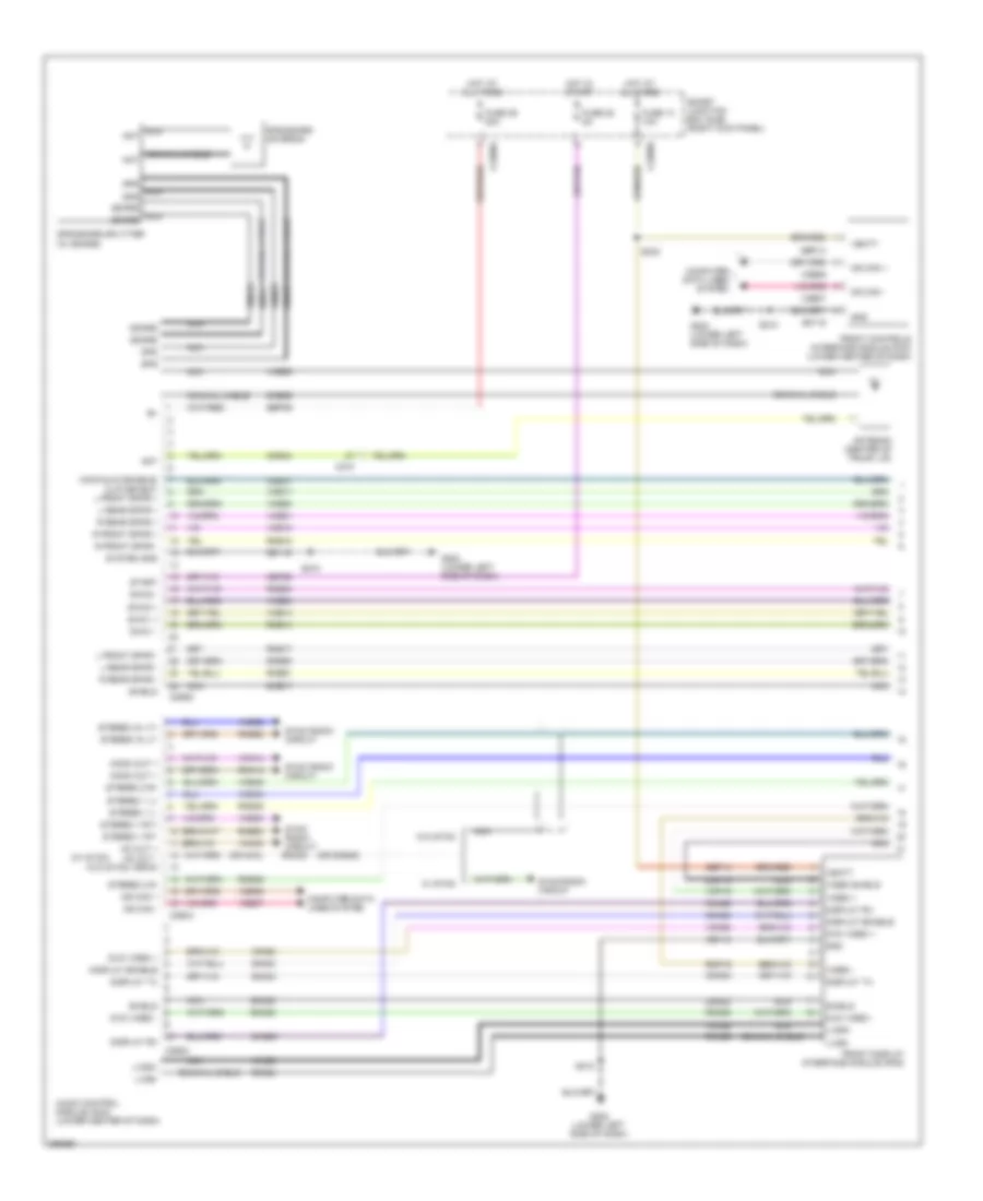 https://portal-diagnostov.com/license.html
Automotive Electricians Portal FZCO
Automotive Electricians Portal FZCO
https://portal-diagnostov.com/license.html
https://portal-diagnostov.com/license.html
Automotive Electricians Portal FZCO
Automotive Electricians Portal FZCOList of elements for Navigation Wiring Diagram (1 of 3) for Ford Mustang GT 2013:
- (or dme45)
- (or nca)
- (w/ sync)
- (w/o sync)
- Ant
- Antenna (center of trunk lid)
- Audio control module (acm) (lower center of dash)
- C210
- C2280a
- C2280b
- C290a
- C290c
- C290d
- Cbp28
- Cme31
- Cme44
- Cmn23
- Cmn24
- Cmn26
- Coaxial cable
- Computer data lines system
- Display enable
- Display rx
- Display tx
- Dme17
- Dme35
- Dme41
- Dmn03
- Dmn20
- Dmp19
- Dvd video +
- Dvd video -
- Front controls interface module (fcm) (lower center of dash)
- Front display interface module (fdim)
- Fuse 14 10a
- Fuse 28 5a
- Fuse 39 20a
- G202 (lower left side of dash)
- Gd115
- Gnd
- Gps
- Gps/sdars antenna
- Gps/sdars splitter (w/ sdars)
- Hot at all times
- Hot in start
- L front spkr -
- L rear spkr +
- L rear spkr -
- Lvds+
- Lvds-
- Main/aux3 enable/ clip detect l front spkr +
- Mc out +
- Mc out - drain
- Mono out +
- Ms can +
- Ms can -
- Nca
- Nca ant
- Nca gps
- Nca sdars
- R front spkr +
- R front spkr -
- R rear spkr +
- R rear spkr -
- Rme14
- Rme17
- Rme18
- Rme45
- Rme46
- Rme52
- Rme53
- Rme54
- Rme60
- Rme61
- Rmn14
- Rmn20
- Rmn25
- Rmp19
- S210
- S232
- Sbp14
- Sbp39
- Sdars
- Shield
- Smart junction box (sjb) (right kick panel)
- Start
- Stereo 1 l+
- Stereo 1 l-
- Stereo 1 rt+
- Stereo 1 rt-
- Stereo 2 r+
- Stereo 2 r-
- Stereo in lt+
- Stereo in lt-
- Swc1 +
- Swc1 -
- Swc2 +
- Swc2 -
- Sync radio circuit
- Sync radio circuit rmm23
- System gnd
- Vbatt
- Vdb06
- Vdb07
- Video +
- Video -
- Video shield
- Vme14
- Vme17
- Vme18
- Vme35
- Vme43
- Vme45
- Vme46
- Vme52
- Vme53
- Vme54
- Vme60
- Vme61
- Vmm23
- Vmn03
- Vmn14
- Vmn20
- Vmn25
- Vmp19
- W/ sync
- W/o sync
Navigation Wiring Diagram (2 of 3) for Ford Mustang GT 2013
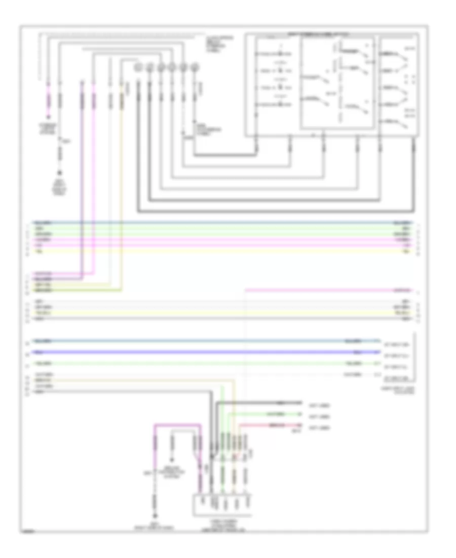 https://portal-diagnostov.com/license.html
Automotive Electricians Portal FZCO
Automotive Electricians Portal FZCO
https://portal-diagnostov.com/license.html
https://portal-diagnostov.com/license.html
Automotive Electricians Portal FZCO
Automotive Electricians Portal FZCOList of elements for Navigation Wiring Diagram (2 of 3) for Ford Mustang GT 2013:
- (not used)
- Audio input jack (w/o sync)
- C210
- C2274a
- C2274b
- C260
- C919
- Clock spring (below steering wheel)
- G201 (right side of dash)
- Gnd
- Ground distribution system
- Interior lights system
- Media
- Nca
- Phone
- Right steering wheel switch
- S201
- S298
- S299 (in steering wheel)
- Seek+
- Seek-
- St input 2l+
- St input 2l-
- St input 2r+
- St input 2r-
- Video +
- Video -
- Video camera (if equipped) (center of trunk lid)
- Video shield
- Voice
- Vol+
- Vol-
- Vpwr
Navigation Wiring Diagram (3 of 3) for Ford Mustang GT 2013
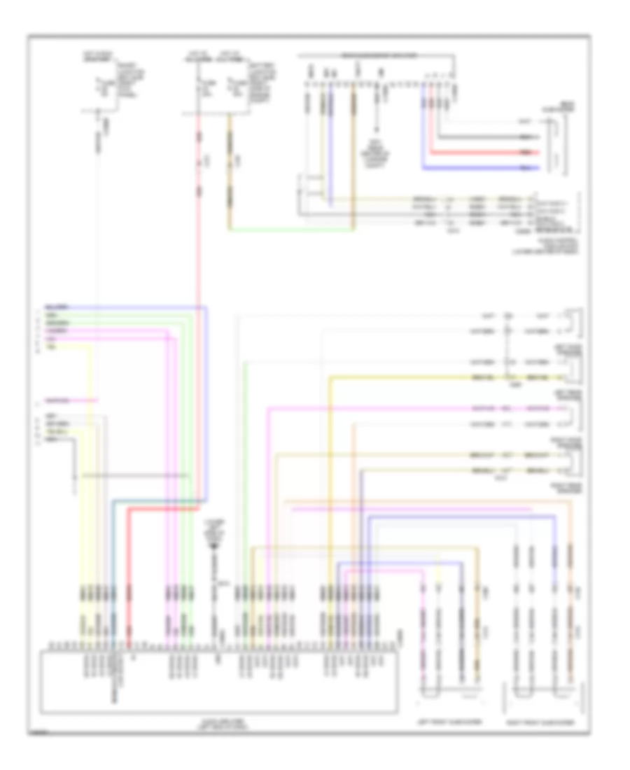 https://portal-diagnostov.com/license.html
Automotive Electricians Portal FZCO
Automotive Electricians Portal FZCO
https://portal-diagnostov.com/license.html
https://portal-diagnostov.com/license.html
Automotive Electricians Portal FZCO
Automotive Electricians Portal FZCOList of elements for Navigation Wiring Diagram (3 of 3) for Ford Mustang GT 2013:
- (lower left side of dash) g202
- Audio amplifier (left end of dash)
- Audio control module (acm) (lower center of dash)
- Aux aud 2 +
- Aux aud 2 -
- Battery junction box (bjb) (right side of engine compt)
- C210
- C211
- C213
- C214
- C2280b
- C237
- C2385a
- C2385b
- C260
- C290b
- C4109a
- C4109b
- Clip detect main/aux3 enable/ lf spkr-
- Cme31
- Dme51
- Fuse 30a
- Fuse 5a
- G401 (rear center of luggage compt)
- Gd115
- Gnd
- Hot at all times
- Hot in run or start
- Inp+
- Inp-
- Left door speaker
- Left front subwoofer
- Left rear speaker
- Lf spkr+
- Lf spkr-
- Lr spkr+
- Lr spkr-
- Mute
- Nca
- Out+
- Out-
- Rear subwoofer
- Rear subwoofer amplifier
- Red
- Rf spkr+
- Rf spkr-
- Right door speaker
- Right front subwoofer
- Right rear speaker
- Rme07
- Rme09
- Rme10
- Rme12
- Rme17
- Rme18
- Rme51
- Rme60
- Rme61
- Rme74
- Rme75
- Rme76
- Rme77
- Rr spkr+
- Rr spkr-
- S210
- Sbb33
- Shield aux aud 2 enable/mute
- Smart junction box (sjb) (right kick panel)
- Sme51
- Vbatt
- Vme07
- Vme09
- Vme10
- Vme12
- Vme17
- Vme18
- Vme51
- Vme60
- Vme61
- Vme74
- Vme75
- Vme76
- Vme77
Parking Assistant Wiring Diagram for Ford Mustang GT 2013
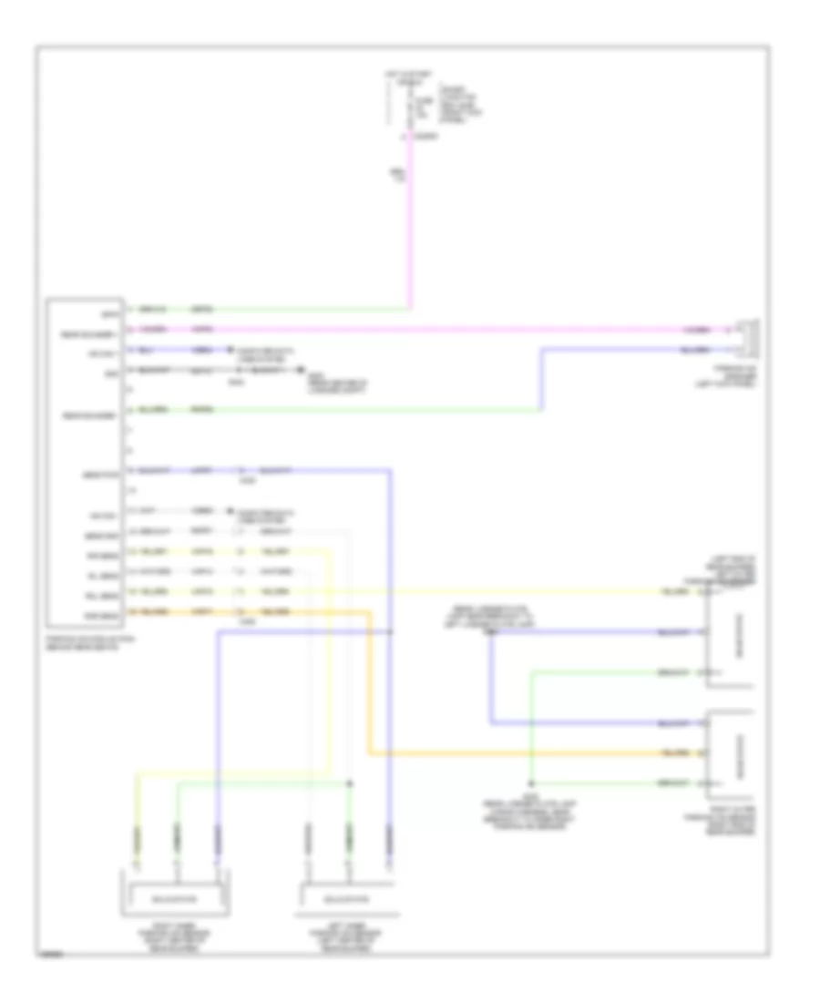 https://portal-diagnostov.com/license.html
Automotive Electricians Portal FZCO
Automotive Electricians Portal FZCO
https://portal-diagnostov.com/license.html
https://portal-diagnostov.com/license.html
Automotive Electricians Portal FZCO
Automotive Electricians Portal FZCOList of elements for Parking Assistant Wiring Diagram for Ford Mustang GT 2013:
- (left end of rear bumper) left outer parking aid sensor
- (rear license plate lamp near breakout to left license plate lamp) s403
- C2280d
- C405
- Cbp32
- Computer data lines system
- Fuse 10a
- G402 (rear center of luggage compt)
- Gd110
- Gnd
- Hot in start or run
- Hs can +
- Hs can -
- Isp-r
- Left inner parking aid sensor (left center of rear bumper)
- Lmp07
- Parking aid module (pam) (behind rear seats)
- Parking aid speaker (left kick panel)
- Rear sounder +
- Rear sounder -
- Right inner parking aid sensor (right center of rear bumper)
- Right outer parking aid sensor (right end of rear bumper)
- Ril sens
- Rir sens
- Rmp07
- Rmp09
- Rol sens
- Ror sens
- S402 (rear license plate lamp wiring harness, near breakout to inner right parking aid sensor)
- S404
- Sens gnd
- Sens pwr
- Smart junction box (sjb) (right kick panel)
- Solid state
- Vdb04
- Vdb05
- Vmp03
- Vmp14
- Vmp15
- Vmp16
- Vmp17
Rear Camera Wiring Diagram for Ford Mustang GT 2013
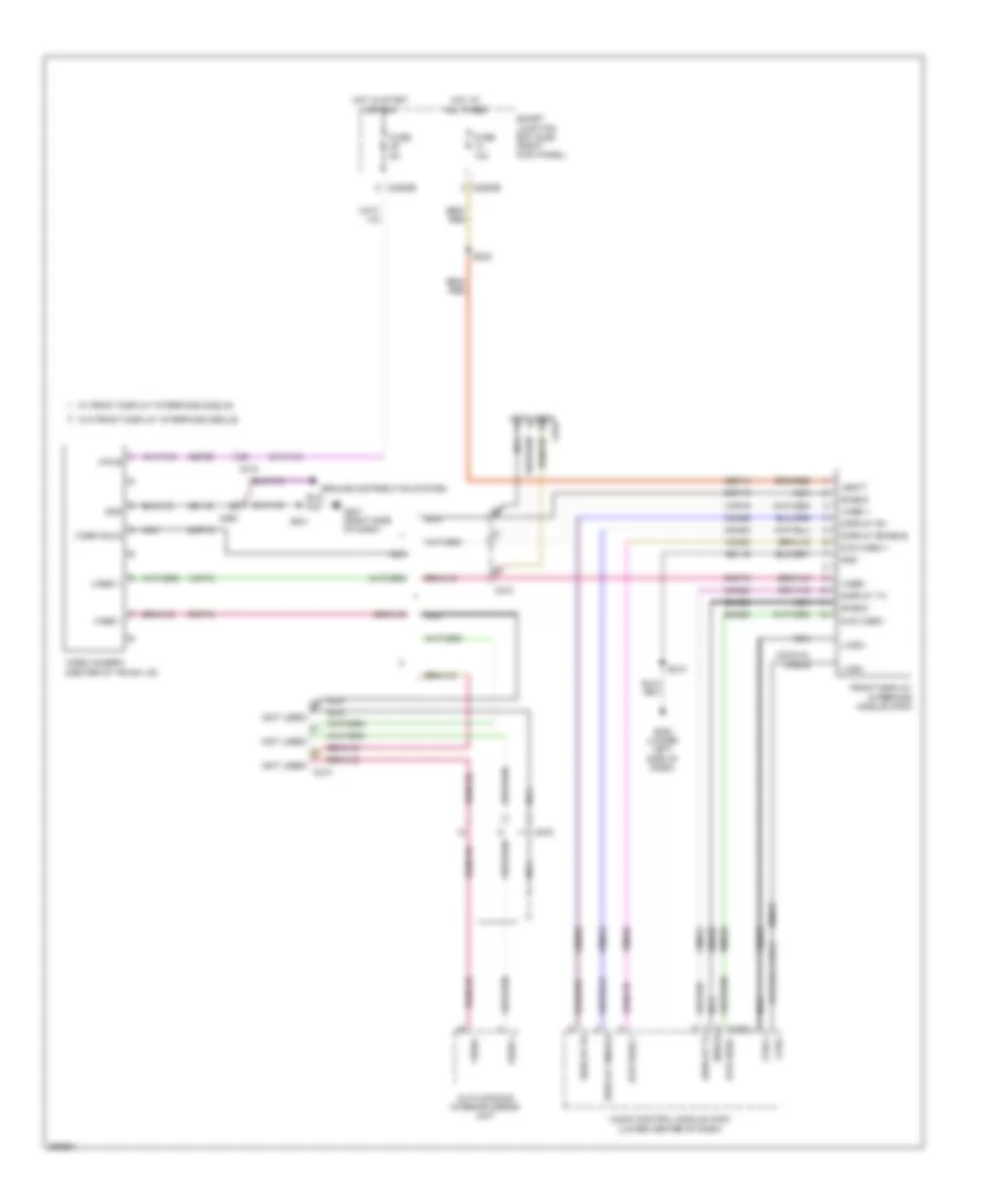 https://portal-diagnostov.com/license.html
Automotive Electricians Portal FZCO
Automotive Electricians Portal FZCO
https://portal-diagnostov.com/license.html
https://portal-diagnostov.com/license.html
Automotive Electricians Portal FZCO
Automotive Electricians Portal FZCOList of elements for Rear Camera Wiring Diagram for Ford Mustang GT 2013:
- (not used)
- (not used) c210
- (not used) c919
- Audio control module (acm) (lower center of dash)
- Auto dimming interior mirror unit
- C210
- C2280b
- C260
- C290c dvd video -
- C919
- Cbp29
- Cmn23
- Cmn24
- Cmn26
- Coaxial cable
- Display enable
- Display rx
- Display tx
- Dmn20
- Dmp19
- Dvd video +
- Dvd video -
- Front display interface module (fdim)
- Fuse 10a
- Fuse 5a
- G201 (right side of dash)
- G202 (lower left side of dash)
- Gd115
- Gd116
- Gnd
- Ground distribution system
- Hot at all times
- Hot in start or run
- Lvds +
- Lvds -
- Nca
- Rmn20
- Rmn25
- Rmp19
- S201
- S210
- S232
- Sbp14
- Shield
- Smart junction box (sjb) (right kick panel)
- Vbatt
- Video +
- Video -
- Video camera (center of trunk lid)
- Video shld
- Vmn20
- Vmn25
- Vmp19
- Vpwr
- W/ front display interface module
- W/o front display interface module
POWER DISTRIBUTION
Power Distribution Wiring Diagram (1 of 5) for Ford Mustang GT 2013
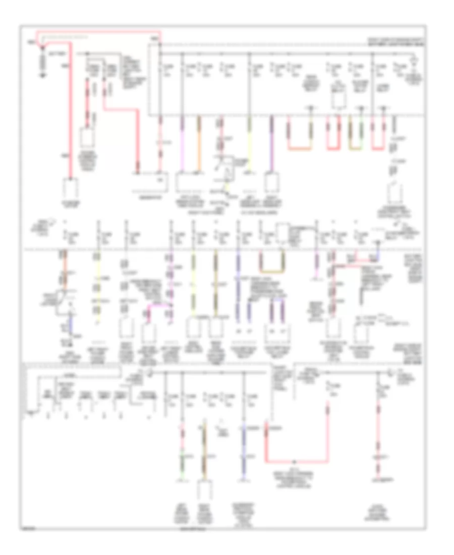 https://portal-diagnostov.com/license.html
Automotive Electricians Portal FZCO
Automotive Electricians Portal FZCO
https://portal-diagnostov.com/license.html
https://portal-diagnostov.com/license.html
Automotive Electricians Portal FZCO
Automotive Electricians Portal FZCOList of elements for Power Distribution Wiring Diagram (1 of 5) for Ford Mustang GT 2013:
- (body main harness,near breakout to passenger side scuff plate lamp) s307
- (near breakout driver's side front seat control switch) s302
- (not used)
- (right side of engine compt) battery junction box (bjb)
- (w/ hid headlamps)
- 3.7l
- 3rd row seat enable (fet)
- A/c clutch relay
- Accessory protocol interface module (apim) (w/ sync)
- Anti-lock brake system (abs) module
- Audio amplifier (shaker/ shaker pro)
- Battery
- Battery junction box (bjb) (right side of engine compt)
- Blower motor relay
- Body control module b
- Brake pedal position (bpp) switch
- Bsi (fet)
- C110
- C1381b
- C1463a
- C1617a
- C1617b
- C175b
- C211
- C2280g
- C237
- C2385a
- C264
- C265
- C300
- C311
- C406
- C4100
- C4368a
- Convertible
- Convertible top lower relay
- Convertible top raise relay
- D6 c213
- D6 c214
- Differential fluid pump relay (5.8l)
- Driver side front seat control switch
- Evaporative emission canister vent valve
- Except 3.7l
- From a fuse 31 (diagram 1 of 5)
- From fuse 19 b (diagram 1 of 5)
- Front cigar lighter
- Fuse 10a
- Fuse 15a
- Fuse 20a
- Fuse 30a
- Fuse 40a
- Fuse 80a
- G200 (right side
- G203 (right kick panel)
- Generator
- High current battery junction box (right rear of engine compt)
- Keypad illum (fet)
- Left front lumbar control switch
- Left front power window motor
- Left headlamp assembly
- Left rear power window motor
- Mega fuse 100a
- Mega fuse 200a
- Micro
- Of dash)
- Passenger side front seat control switch
- Power point
- Power steering control module (pscm)
- Powertrain control module
- Rear sub- woofer amplifier (shaker pro)
- Rear window defrost relay
- Red
- Right front power window motor
- Right headlamp assembly
- Right rear power window motor
- S114 (body main harness, near breakout to powertrain control module)
- S143
- S200
- S319
- Smart junction box (sjb) (right kick panel)
- Starter motor
- Starter relay
- To fuse 1 (diagram 1 of 5)
- To fuse 21 (diagram 2 of 5)
- To fuse 22 (diagram 1 of 5)
- To fuse 6 (diagram 3 of 5)
- Tpms 1 (fet)
- Tpms 2 (fet)
- Tpms 3 (fet)
- Vbatt
- Wiper relay
Power Distribution Wiring Diagram (2 of 5) for Ford Mustang GT 2013
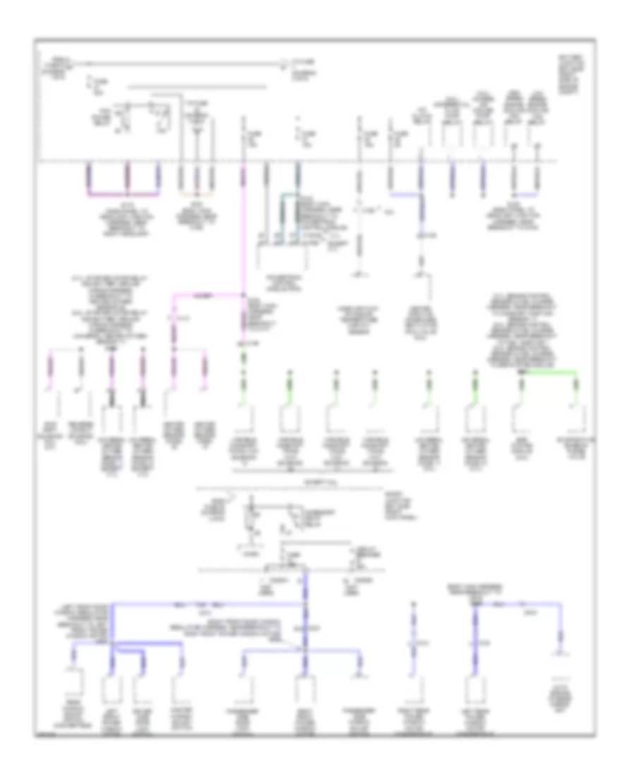 https://portal-diagnostov.com/license.html
Automotive Electricians Portal FZCO
Automotive Electricians Portal FZCO
https://portal-diagnostov.com/license.html
https://portal-diagnostov.com/license.html
Automotive Electricians Portal FZCO
Automotive Electricians Portal FZCOList of elements for Power Distribution Wiring Diagram (2 of 5) for Ford Mustang GT 2013:
- (3.7l: engine control sensor & fuel charge harness, near breakout to camshaft position sensor 11) (5.0l: engine control sensor & fuel charge harness, near breakout to fuel injector 1 (5.8l: engine control sensor & fuel charge harness, near breakout to egr system module) s101
- (3.7l: starter motor relay and battery ground wiring harness, in breakout to heated oxygen sensor 22) (5.0l: starter motor relay and battery ground wiring harness, in breakout to universal heated oxygen sensor 11) s139
- (5.8l) charge air cooler pump relay
- (5.8l) differential fluid pump relay
- (body main harness, near breakout to c919) s326
- (left front door window regulator harness, near breakout to left front power window motor) s500
- (not used)
- (right front door window regulator harness, near breakout to right front power window motor) s600
- 3.7l
- 5.8l
- A/c clutch relay
- Accessory delay relay
- Auto dimming interior mirror unit
- Battery junction box (bjb) (right side of engine compt)
- C110
- C1381b
- C146
- C175b
- C192
- C213 b10
- C214
- C2280a
- C2280d
- C312
- C919
- Circuit breaker 30a
- Driver side door lock switch
- Egr system module (5.8l)
- Evaporative emission purge valve
- Except 3.7l
- Except 5.8l
- From fuse 33 c (diagram 1 of 5)
- Fuse 15a
- Fuse 30a
- Fuse 5a
- Heated oxygen sensor (ho2s)
- Heated positive crankcase ventilation (pcv) valve (5.8l)
- High speed engine cooling fan relay
- J from fuse 23 (diagram 4 of 5)
- Left front power window motor
- Left rear power window motor (convertible)
- Low speed engine cooling fan relay
- Mass air flow/ intake air temperature (maf/iat) sensor
- Master window adjust switch
- Micro
- Nca
- Passenger side door lock switch
- Passenger side window adjust switch
- Pcm power relay
- Powertrain control module (pcm)
- Rear window adjust switch (convertible)
- Reverse lockout solenoid (5.8l)
- Right front power window motor
- Right rear power window motor (convertible)
- S116 (dash panel to headlamp junction harness, near breakout to right headlamp)
- S120 (body main harness, near breakout to c192)
- S123 (body main harness, near breakout to powertrain control module)
- S124 (body main harness, near breakout to c177)
- S125 (dash panel to headlamp junction harness, near breakout to g100)
- Skip shift solenoid (5.0l m/t)
- Smart junction box (sjb) (right kick panel)
- To fuse (diagram 3 of 5)
- Universal heated oxygen sensor (ho2s) 11 (3.7l)
- Universal heated oxygen sensor (ho2s) 11 (except 3.7l)
- Universal heated oxygen sensor (ho2s) 21 (3.7l)
- Universal heated oxygen sensor (ho2s) 21 (except 3.7l)
- Variable camshaft timing (vct) solenoid
Power Distribution Wiring Diagram (3 of 5) for Ford Mustang GT 2013
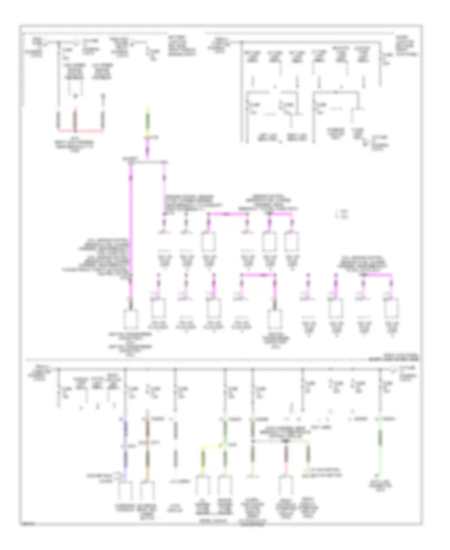 https://portal-diagnostov.com/license.html
Automotive Electricians Portal FZCO
Automotive Electricians Portal FZCO
https://portal-diagnostov.com/license.html
https://portal-diagnostov.com/license.html
Automotive Electricians Portal FZCO
Automotive Electricians Portal FZCOList of elements for Power Distribution Wiring Diagram (3 of 5) for Ford Mustang GT 2013:
- (5.0l: engine control sensor & fuel charge harness, near breakout fuel injector 4) (5.8l: engine control sensor & fuel charge harness, near breakout to electronic throttle control control motor) s104
- (5.8l: engine control sensor & fuel charge harness, near breakout to coil on plug 4) s119
- (boss laguna)
- (engine control sensor & fuel charge harness, near breakout to camshaft position sensor 11) s119
- (engine control sensor & fuel charge harness, near breakout to fuel injector 5) s104
- (main harness, near breakout to restraints control module) s232
- (not used)
- (right kick panel) smart junction box (sjb)
- (w/ navigation)
- (w/o navigation)
- 3.7l
- 5.0l
- 5.8l
- Back- lighting led (fet)
- Battery junction box (bjb) (right side of engine compt)
- C146
- C214
- C2280a
- C2280b
- C2280d
- C275
- C294a
- C913
- Coil on plug (cop)
- Convertible
- Coupe
- Data link connector (dlc)
- Engine temper- ature gauge
- Except 3.7l
- Exterior rear view mirror switch
- Floor lamp (fet)
- From fuse 5 m (diagram 1 of 5)
- From fuse 9 g (diagram 3 of 5)
- From fuse d (diagram 2 of 5)
- From pcm power e relay (diagram 2 of 5)
- Front controls interface module (fcim)
- Front display interface module (fdim)
- Fuse 10a
- Fuse 15a
- Fuse 20a
- Fuse 25a
- Fuse 40a
- Fuse 5a
- Fuse 7.5a
- Global positioning system module (gpsm) (w/ sync & w/o navigation)
- High speed engine cooling fan relay
- Hvac module
- Ignition transformer capacitor 1 (5.8l)
- Ignition transformer capacitor 2 (5.8l) ignition transformer capacitor 1 (5.0l)
- Interior lighting (fet)
- Left low beam (fet)
- Lf turn lamp (fet)
- Low speed engine cooling fan relay
- Lr stop/ turn lamp (fet)
- Lr turn lamp (fet)
- Oil temper- ature gauge
- Overhead console
- Puddle lamp (fet)
- Rf turn lamp (fet)
- Right low beam (fet)
- Rr stop/ turn lamp (fet)
- Rr turn lamp (fet)
- S121 (body main harness, near breakout to c192)
- Smart junction box (sjb) (right kick panel)
- To fuse (diagram 3 of 5)
- To fuse (diagram 4 of 5)
- White light (fet)
Power Distribution Wiring Diagram (4 of 5) for Ford Mustang GT 2013
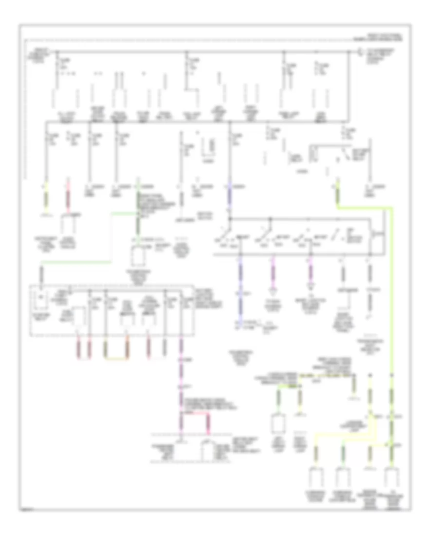 https://portal-diagnostov.com/license.html
Automotive Electricians Portal FZCO
Automotive Electricians Portal FZCO
https://portal-diagnostov.com/license.html
https://portal-diagnostov.com/license.html
Automotive Electricians Portal FZCO
Automotive Electricians Portal FZCOList of elements for Power Distribution Wiring Diagram (4 of 5) for Ford Mustang GT 2013:
- (3.7l)
- (5.8l) charge air cooler pump relay
- (5.8l) fuel pump relay 2
- (body main wiring harness, near breakout to smart junction box) s209
- (diagram 5 of 5)
- (except 3.7l)
- (not used)
- (power seats wiring harness, near breakout to heated seat relay box) s304
- (right kick panel) smart junction box (sjb)
- 3.7l
- Acc
- All lock/ unlock relay
- Audio control module
- Audio control module (acm)
- Battery junction box (bjb) (right side of engine compt)
- Battery saver relay
- C1381b
- C175b
- C210
- C211
- C2280a
- C2280b
- C2280d
- C2280e
- C265
- C275
- C290d
- C311
- C913
- C919
- Driver door unlock relay
- Driver heated seat relay
- Engine temperature gauge (boss laguna)
- Except 3.7l
- Fog lamp relay
- From f fuse 7 (diagram 3 of 5)
- From fuse 20 h (diagram 3 of 5)
- Fuel pump relay
- Fuse 10a
- Fuse 15a
- Fuse 20a
- Fuse 5a
- Heated seat relay box (under driver's seat)
- High beam relay
- Horn relay
- Ignition switch
- Instrument panel cluster (ipc)
- Key in ignition switch
- Left corner lamp (fet)
- Left vanity mirror lamp
- Lock
- Luggage compartment lamp
- Micro
- Off
- Oil pressure gauge (boss laguna)
- Overhead console (convertible)
- Overhead console (coupe)
- Park lamp relay
- Passenger heated seat relay
- Powertrain control module (pcm)
- Pulse train (fet)
- Right corner lamp (fet)
- Right vanity mirror lamp
- Run
- Smart junction box (sjb) (right kick panel)
- Start
- Starter relay
- To accessory delay relay (diagram 2 of 5)
- To s240
- To smart junction box (sjb) (diagram 5 of 5)
- Transmission shift selector (a/t)
- Trunk rel (fet)
- Trunk release relay
Power Distribution Wiring Diagram (5 of 5) for Ford Mustang GT 2013
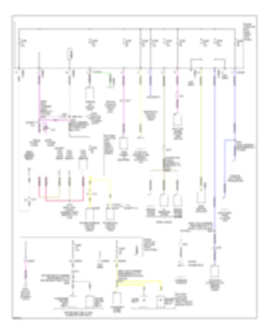 https://portal-diagnostov.com/license.html
Automotive Electricians Portal FZCO
Automotive Electricians Portal FZCO
https://portal-diagnostov.com/license.html
https://portal-diagnostov.com/license.html
Automotive Electricians Portal FZCO
Automotive Electricians Portal FZCOList of elements for Power Distribution Wiring Diagram (5 of 5) for Ford Mustang GT 2013:
- (5.8l) fuel pump relay 1
- (5.8l) fuel pump relay 2
- (body main harness, near breakout to c192) s126
- (body main harness, near breakout to powertrain control module) s130
- (body main harness, near breakout to smart junction box) s237
- (except 5.8l) fuel pump relay
- (not used)
- 3.7l
- 5.8l
- Anti-lock brake system (abs) module
- Battery junction box (bjb) (right side of engine compt)
- Blower motor relay
- Body control module b
- Boss laguna
- C110
- C1381b
- C1463b
- C175b
- C2041a
- C210
- C211
- C2280a
- C2280b
- C2280d
- C2280e
- C275
- C300
- C311
- C4368a
- C4396b
- C913
- Convertible
- Coupe
- Driver heated seat relay
- Engine temper- ature gauge
- Except 3.7l
- Except 5.8l
- From ignition switch (diagram 4 of 5)
- Fuse 10a
- Fuse 5a
- Fuse 7.5a
- Heated seat relay box (under driver's seat)
- In-vehicle temperature sensor (automatic a/c)
- Instrument panel cluster (ipc)
- Micro
- Occupant classification sensor module (ocsm)
- Oil pressure gauge
- Overhead console
- Parking aid module (pam)
- Passenger heated seat relay
- Passive anti-theft transceiver
- Pcm power diode
- Perfor- mance gauge
- Power steering control module (pscm)
- Powertrain control module (pcm)
- Rear window defrost relay
- Restraints control module (rcm)
- S122 (body main wiring harness, near breakout to c192)
- S236 (main harness, near breakout to g202)
- Smart junction box (sjb) (right kick panel)
- Vehicle dynamics module (vdm) (5.8l)
- Video camera (if equipped)
- Windshield wiper motor
- Wiper relay
POWER DOOR LOCKS
Power Door Locks Wiring Diagram (1 of 2) for Ford Mustang GT 2013
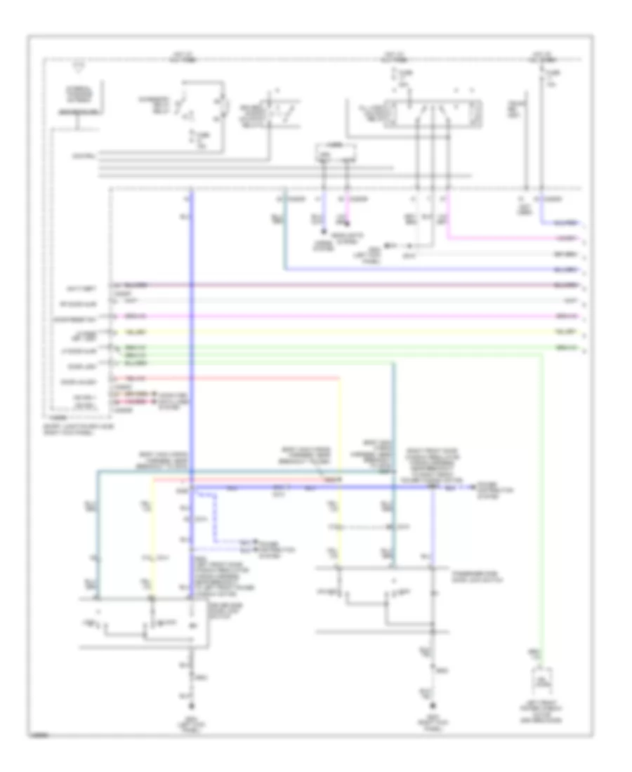 https://portal-diagnostov.com/license.html
Automotive Electricians Portal FZCO
Automotive Electricians Portal FZCO
https://portal-diagnostov.com/license.html
https://portal-diagnostov.com/license.html
Automotive Electricians Portal FZCO
Automotive Electricians Portal FZCOList of elements for Power Door Locks Wiring Diagram (1 of 2) for Ford Mustang GT 2013:
- (body main wiring harness, near breakout to c260)
- (body main wiring harness, near breakout to c919)
- (body main wiring harness, near breakout to c919) s327
- (not used)
- (right front door window regulator wiring harness, near breakout to right front power window motor) s600
- Accessory delay relay
- All lock/ unlock relay
- Anti-theft
- Auto
- B10
- C10
- C213
- C214
- C2280b
- C2280c
- C2280d
- C2280f
- Computer data lines system
- Control
- Door lock
- Door reset sw
- Door unlock
- Dr ajar
- Driver door unlock relay
- Driver side door lock switch
- Fuse 10a
- Fuse 15a
- Fuse 20a
- G203 (right kick panel)
- G204 (left kick panel)
- Headlights system
- Horns system
- Hot at all times
- Hrn rly
- Internal tpms/rke antenna
- Left front power window motor (driver's door)
- Lf door ajar
- Lf door key lock
- Lock
- Micro
- Ms can +
- Ms can -
- Passenger side door lock switch
- Power distribution system
- Rf door ajar
- Rke receiver
- S215
- S248
- S326
- S500 (left front door window regulator wiring harness, near breakout to left front power window motor)
- S503
- S602
- Smart junction box (sjb) (right kick panel)
- Trunk rel (fet)
- Unlock
Power Door Locks Wiring Diagram (2 of 2) for Ford Mustang GT 2013
 https://portal-diagnostov.com/license.html
Automotive Electricians Portal FZCO
Automotive Electricians Portal FZCO
https://portal-diagnostov.com/license.html
https://portal-diagnostov.com/license.html
Automotive Electricians Portal FZCO
Automotive Electricians Portal FZCOList of elements for Power Door Locks Wiring Diagram (2 of 2) for Ford Mustang GT 2013:
- Body control module b (right rear of luggage compt)
- C11
- C213 c8
- C214 c7
- C4368a
- C7 c213
- C8 c214
- C913
- Close
- Convertible
- Coupe
- Dr ajar
- Driver door latch (driver's door)
- G100
- G203 (right kick panel)
- G204 (left kick panel)
- Hood switch (right front of engine compt)
- Intrusions sense
- Ism ground
- Ism power
- Lin
- Open
- Overhead console
- Passenger door latch (front passenger's door)
- Reset
- Right front power window motor (front passenger's door)
- S112
- S233 (body main wiring harness, near breakout to c260)
- S328
- S503
- S602
- Set
POWER MIRRORS
Electrochromic Mirror Wiring Diagram, with Rear View Camera for Ford Mustang GT 2013
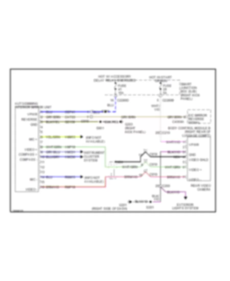 https://portal-diagnostov.com/license.html
Automotive Electricians Portal FZCO
Automotive Electricians Portal FZCO
https://portal-diagnostov.com/license.html
https://portal-diagnostov.com/license.html
Automotive Electricians Portal FZCO
Automotive Electricians Portal FZCOList of elements for Electrochromic Mirror Wiring Diagram, with Rear View Camera for Ford Mustang GT 2013:
- (info not available)
- Auto-dimming interior mirror unit
- Body control module b (right rear of luggage compt)
- C210
- C2280b
- C2280d
- C260
- C4368a
- C919
- Cat03
- Cbp41
- Compass +
- Compass -
- E/c mirror reverse signal
- Exterior lights system
- Fuse 15a
- Fuse 5a
- G201 (right side of dash)
- G203 (right kick panel)
- Gd139
- Gnd
- Hot in start or run
- Hot w/ accessory delay relay energized
- Instrument cluster system
- Mic +
- Mic -
- Nca
- Rear video camera
- Reverse
- Rmm13
- Rmp19
- S201
- S326
- S901
- Smart junction box (sjb) (right kick panel)
- Video +
- Video -
- Video shld
- Vmc30
- Vmc31
- Vmm13
- Vmp19
- Vpwr
Electrochromic Mirror Wiring Diagram, without Rear View Camera for Ford Mustang GT 2013
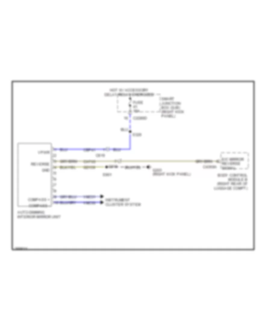 https://portal-diagnostov.com/license.html
Automotive Electricians Portal FZCO
Automotive Electricians Portal FZCO
https://portal-diagnostov.com/license.html
https://portal-diagnostov.com/license.html
Automotive Electricians Portal FZCO
Automotive Electricians Portal FZCOList of elements for Electrochromic Mirror Wiring Diagram, without Rear View Camera for Ford Mustang GT 2013:
- Auto-dimming interior mirror unit
- Body control module b (right rear of luggage compt)
- C2280d
- C4368a
- C919
- Cat03
- Cbp41
- Compass +
- Compass -
- E/c mirror reverse signal
- Fuse 15a
- G203 (right kick panel)
- Gd139
- Gnd
- Hot w/ accessory delay relay energized
- Instrument cluster system
- Reverse
- S326
- S901
- Smart junction box (sjb) (right kick panel)
- Vmc30
- Vmc31
- Vpwr
Power Mirrors Wiring Diagram for Ford Mustang GT 2013
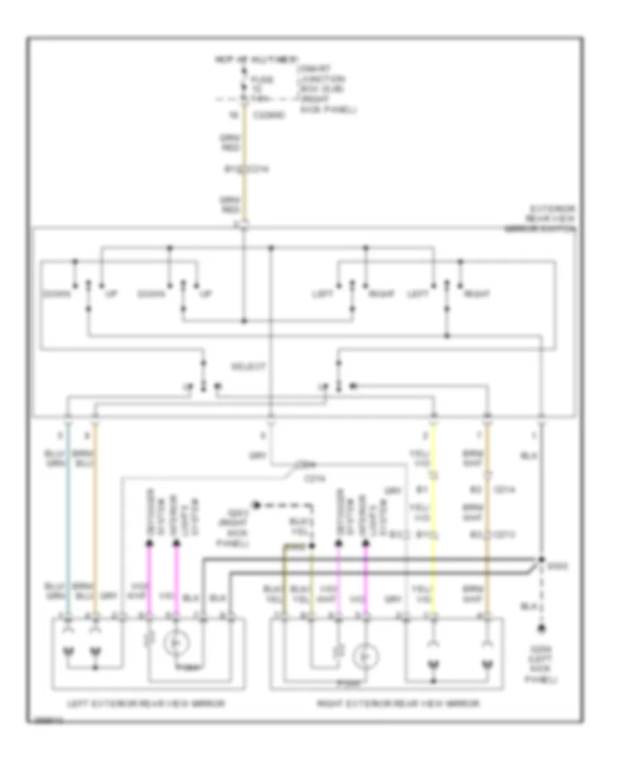 https://portal-diagnostov.com/license.html
Automotive Electricians Portal FZCO
Automotive Electricians Portal FZCO
https://portal-diagnostov.com/license.html
https://portal-diagnostov.com/license.html
Automotive Electricians Portal FZCO
Automotive Electricians Portal FZCOList of elements for Power Mirrors Wiring Diagram for Ford Mustang GT 2013:
- B12 c214
- C213
- C214
- C2280d
- Defogger system
- Down
- Exterior rear view mirror switch
- Fuse 7.5a
- G203 (right kick
- G204 (left kick
- Hot at all times
- Interior
- Left
- Left exterior rear view mirror
- Panel)
- Pony
- Right
- Right exterior rear view mirror
- S503
- S602
- Select
- Smart junction box (sjb) (right kick panel)
- System lights
- System lights interior
POWER SEATS
Heated Seats Wiring Diagram for Ford Mustang GT 2013
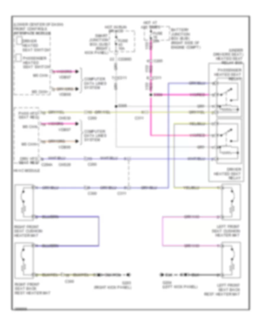 https://portal-diagnostov.com/license.html
Automotive Electricians Portal FZCO
Automotive Electricians Portal FZCO
https://portal-diagnostov.com/license.html
https://portal-diagnostov.com/license.html
Automotive Electricians Portal FZCO
Automotive Electricians Portal FZCOList of elements for Heated Seats Wiring Diagram for Ford Mustang GT 2013:
- (lower center of dash) front controls interface module
- (under driver's seat) heated seat relay box
- Battery junction box (bjb) (right side of engine compt)
- C2280d
- C260
- C265
- C300
- C311
- Chs29
- Chs30
- Computer data lines system
- Driv htd
- Driver heated seat relay
- Driver heated seat switch
- Fuse 10a
- Fuse 20a
- G203 (right kick panel)
- G204 (left kick panel)
- Hot at all times
- Hot in run or acc
- Hvac module
- Left front seat back rest heater mat
- Left front seat cushion heater mat
- Ms can+
- Ms can-
- Pass htd seat req
- Passenger heated seat relay
- Passenger heated seat switch
- Right front seat back rest heater mat
- Right front seat cushion heater mat
- S303
- S304
- S305
- S328
- Seat req c294a
- Smart junction box (sjb) (right kick panel)
- Vdb06
- Vdb07
Lumbar Wiring Diagram for Ford Mustang GT 2013
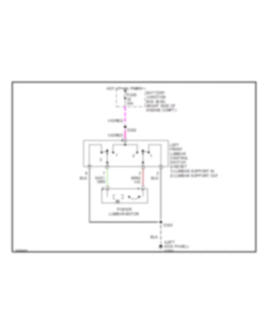 https://portal-diagnostov.com/license.html
Automotive Electricians Portal FZCO
Automotive Electricians Portal FZCO
https://portal-diagnostov.com/license.html
https://portal-diagnostov.com/license.html
Automotive Electricians Portal FZCO
Automotive Electricians Portal FZCOList of elements for Lumbar Wiring Diagram for Ford Mustang GT 2013:
- (left kick panel) g204
- Battery junction box (bjb) (right side of engine compt)
- Fuse 30a
- Hot at all times
- Left front lumbar control switch 0) reset 1) lumbar support in 2) lumbar support out
- Power lumbar motor
- S302
- S303
Power Seats Wiring Diagram for Ford Mustang GT 2013
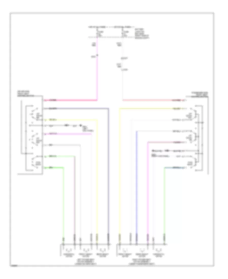 https://portal-diagnostov.com/license.html
Automotive Electricians Portal FZCO
Automotive Electricians Portal FZCO
https://portal-diagnostov.com/license.html
https://portal-diagnostov.com/license.html
Automotive Electricians Portal FZCO
Automotive Electricians Portal FZCOList of elements for Power Seats Wiring Diagram for Ford Mustang GT 2013:
- Battery junction box (bjb) (right side of engine compt)
- C237
- C300
- Driver side front seat control switch
- Front height motor
- Fuse 30a
- Fwd/ back
- G203 (right kick panel)
- G204 (left kick panel)
- Horizontal motor
- Hot at all times
- Left power seat motor assembly (under driver's seat)
- Passenger side front seat control switch
- Rear height motor
- Right power seat motor assembly (under passenger's seat)
- S302
- S303
- S306
- Up/ down frt
- Up/ down rr
POWER TOP/SUNROOF
Power Top/Sunroof Wiring Diagram for Ford Mustang GT 2013
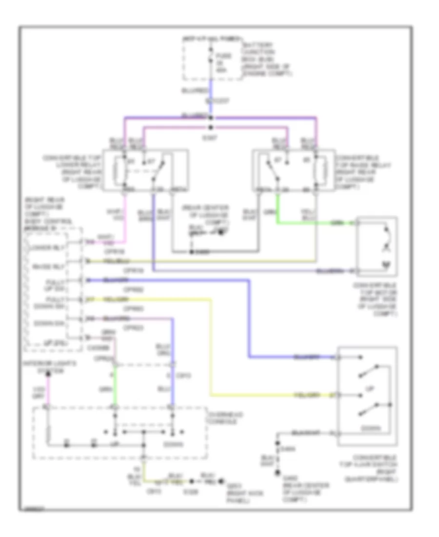 https://portal-diagnostov.com/license.html
Automotive Electricians Portal FZCO
Automotive Electricians Portal FZCO
https://portal-diagnostov.com/license.html
https://portal-diagnostov.com/license.html
Automotive Electricians Portal FZCO
Automotive Electricians Portal FZCOList of elements for Power Top/Sunroof Wiring Diagram for Ford Mustang GT 2013:
- (rear center of luggage compt) g402
- (right rear of luggage compt) body control module b
- 87a
- Battery junction box (bjb) (right side of engine compt)
- C237
- C4368b
- C913
- Convertible top ajar switch (right quarterpanel)
- Convertible top lower relay (right rear of luggage compt)
- Convertible top motor (right side of luggage compt)
- Convertible top raise relay (right rear of luggage compt)
- Cpr18
- Cpr19
- Cpr23
- Cpr24
- Cpr92
- Cpr93
- Down
- Down sw
- Fully down sw
- Fully up sw
- Fuse 40a
- G203 (right kick panel)
- G402 (rear center of luggage compt)
- Hot at all times
- Interior lights system
- Lower rly
- Overhead console
- Raise rly
- S307
- S328
- S400
- S404
- Up sw
POWER WINDOWS
Power Windows Wiring Diagram for Ford Mustang GT 2013
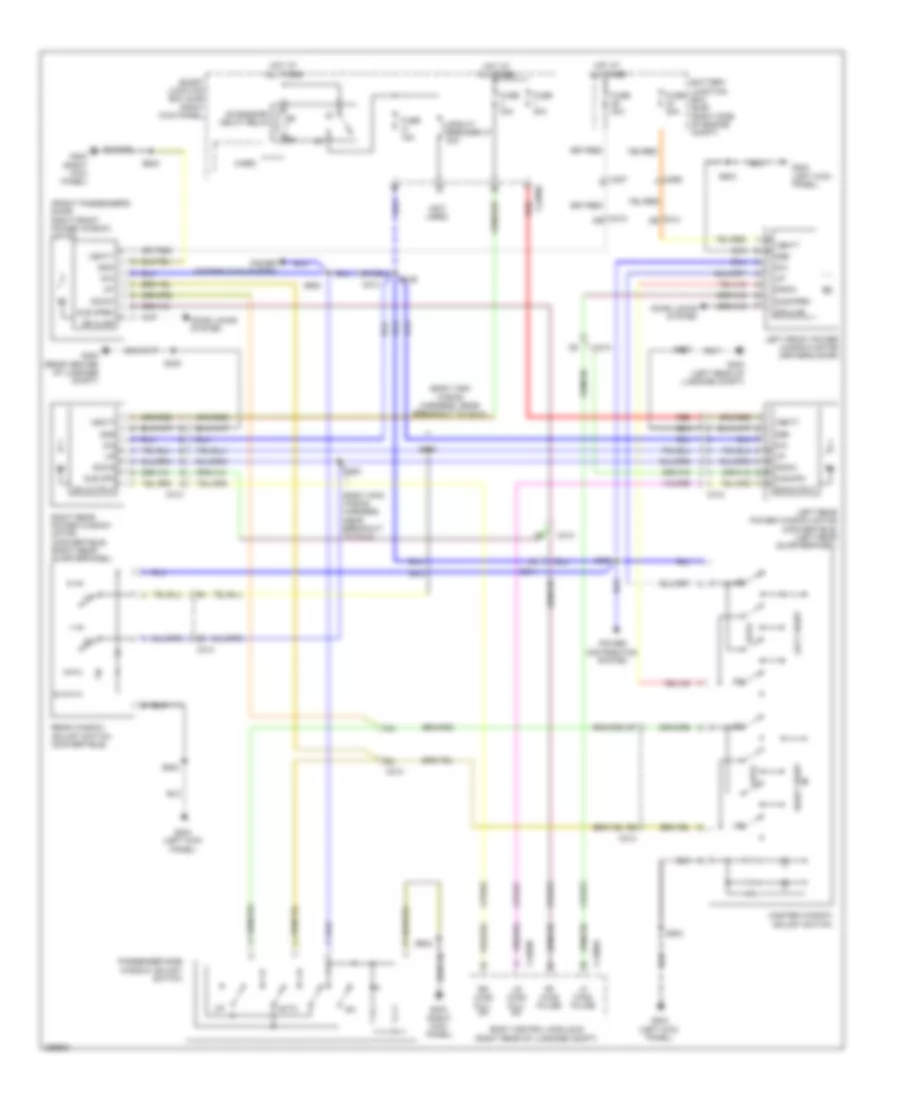 https://portal-diagnostov.com/license.html
Automotive Electricians Portal FZCO
Automotive Electricians Portal FZCO
https://portal-diagnostov.com/license.html
https://portal-diagnostov.com/license.html
Automotive Electricians Portal FZCO
Automotive Electricians Portal FZCOList of elements for Power Windows Wiring Diagram for Ford Mustang GT 2013:
- (body main wiring harness, near breakout to c214)
- (front passenger's door) right front power window motor
- (not used)
- Accessory delay relay
- Auto
- B10
- Battery junction box (bjb) (right side of engine compt)
- Body control module b (right rear of luggage compt)
- C213
- C214
- C2280d
- C237
- C265
- C312
- C313
- C4368a
- C4368b
- Circuit breaker 47 30a
- Cpw47
- Cpw53
- Cpw73
- Dia
- Dn output
- Door locks system
- Down
- Dr ajar
- Fuse 15a
- Fuse 30a
- G203 (right kick panel)
- G204 (left kick panel)
- G400 (left rear of luggage compt)
- G402 (rear center of luggage compt)
- Glb open
- Glb opn
- Gnd
- Hot at all times
- Left front
- Left front power window motor (driver's door)
- Left rear power window motor (convertible) (left rear quarterpanel)
- Lf wind pulse
- Lr wind full dn
- Master window adjust switch
- Micro
- Passenger side window adjust switch
- Power distribution system
- Rear window adjust switch (convertible)
- Red
- Rf wind pulse
- Right front
- Right rear power window motor (convertible) (right rear quarterpanel)
- Rr wind full dn
- S260
- S261
- S326
- S400
- S407
- S500
- S503
- S600
- S602
- Smart junction box (sjb) (right kick panel)
- Vbatt
RADIO
Base Radio Wiring Diagram for Ford Mustang GT 2013
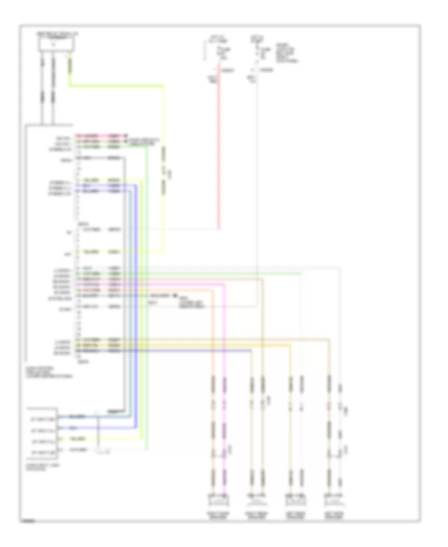 https://portal-diagnostov.com/license.html
Automotive Electricians Portal FZCO
Automotive Electricians Portal FZCO
https://portal-diagnostov.com/license.html
https://portal-diagnostov.com/license.html
Automotive Electricians Portal FZCO
Automotive Electricians Portal FZCOList of elements for Base Radio Wiring Diagram for Ford Mustang GT 2013:
- (center of trunk lid) antenna
- Ant
- Audio control module (acm) (lower center of dash)
- Audio input jack (w/o sync)
- C210
- C213
- C214
- C2280a
- C2280b
- C260
- C290a
- C290d
- Cbp28
- Cme44
- Coaxial cable
- Computer data lines system
- Dme35
- Dme45
- Drain
- Fuse 20a
- Fuse 5a
- G202 (lower left side of dash)
- Gd115
- Hot at all times
- Hot in start
- Left door speaker
- Left rear speaker
- Lf spkr +
- Lf spkr -
- Lr spkr +
- Lr spkr -
- Ms can +
- Ms can -
- Nca
- Rf spkr +
- Rf spkr -
- Right door speaker
- Right rear speaker
- Rme07
- Rme09
- Rme10
- Rme12
- Rme45
- Rme46
- Rr spkr +
- Rr spkr -
- S210
- Sbp39
- Smart junction box (sjb) (right kick panel)
- St input 2l+
- St input 2l-
- St input 2r+
- St input 2r-
- Start
- Stereo 2 l+
- Stereo 2 l-
- Stereo 2 r+
- Stereo 2 r-
- System gnd
- Vdb06
- Vdb07
- Vme07
- Vme09
- Vme10
- Vme12
- Vme35
- Vme45
- Vme46
Premium Radio Wiring Diagram (1 of 3) for Ford Mustang GT 2013
 https://portal-diagnostov.com/license.html
Automotive Electricians Portal FZCO
Automotive Electricians Portal FZCO
https://portal-diagnostov.com/license.html
https://portal-diagnostov.com/license.html
Automotive Electricians Portal FZCO
Automotive Electricians Portal FZCOList of elements for Premium Radio Wiring Diagram (1 of 3) for Ford Mustang GT 2013:
- (or dme45)
- (or nca)
- (w/ sync)
- (w/o sync)
- Ant
- Antenna (center of trunk lid)
- Audio control module (acm) (lower center of dash)
- C210
- C2280a
- C2280b
- C290a
- C290c
- C290d
- Cbp28
- Cme31
- Cme44
- Cmn23
- Cmn24
- Cmn26
- Coaxial cable
- Computer data lines system
- Display enable
- Display rx
- Display tx
- Dme17
- Dme35
- Dme41
- Dmn03
- Dmn20
- Dmp19
- Dvd video +
- Dvd video -
- Front controls interface module (fcm) (lower center of dash)
- Front display interface module (fdim)
- Fuse 14 10a
- Fuse 28 5a
- Fuse 39 20a
- G202 (lower left side of dash)
- Gd115
- Gnd
- Gps
- Gps/sdars antenna
- Gps/sdars splitter (w/ sdars)
- Hot at all times
- Hot in start
- L front spkr -
- L rear spkr +
- L rear spkr -
- Lvds+
- Lvds-
- Main/aux3 enable/ clip detect l front spkr +
- Mc out +
- Mc out - drain
- Mono out +
- Ms can +
- Ms can -
- Nca
- Nca ant
- Nca gps
- Nca sdars
- R front spkr +
- R front spkr -
- R rear spkr +
- R rear spkr -
- Rme14
- Rme17
- Rme18
- Rme45
- Rme46
- Rme52
- Rme53
- Rme54
- Rme60
- Rme61
- Rmn14
- Rmn20
- Rmn25
- Rmp19
- S210
- S232
- Sbp14
- Sbp39
- Sdars
- Shield
- Smart junction box (sjb) (right kick panel)
- Start
- Stereo 1 l+
- Stereo 1 l-
- Stereo 1 rt+
- Stereo 1 rt-
- Stereo 2 r+
- Stereo 2 r-
- Stereo in lt+
- Stereo in lt-
- Swc1 +
- Swc1 -
- Swc2 +
- Swc2 -
- Sync radio circuit
- Sync radio circuit rmm23
- System gnd
- Vbatt
- Vdb06
- Vdb07
- Video +
- Video -
- Video shield
- Vme14
- Vme17
- Vme18
- Vme35
- Vme43
- Vme45
- Vme46
- Vme52
- Vme53
- Vme54
- Vme60
- Vme61
- Vmm23
- Vmn03
- Vmn14
- Vmn20
- Vmn25
- Vmp19
- W/ sync
- W/o sync
Premium Radio Wiring Diagram (2 of 3) for Ford Mustang GT 2013
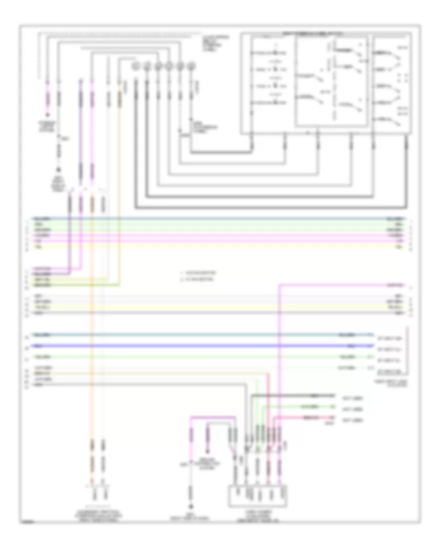 https://portal-diagnostov.com/license.html
Automotive Electricians Portal FZCO
Automotive Electricians Portal FZCO
https://portal-diagnostov.com/license.html
https://portal-diagnostov.com/license.html
Automotive Electricians Portal FZCO
Automotive Electricians Portal FZCOList of elements for Premium Radio Wiring Diagram (2 of 3) for Ford Mustang GT 2013:
- (not used)
- Accessory protocol interface module (apim) (right side of dash)
- Audio input jack (w/o sync)
- C210
- C2274a
- C2274b
- C260
- C919
- Clock spring (below steering wheel)
- G201 (right side of dash)
- Gnd
- Ground distribution system
- Interior lights system
- Media
- Nca
- Phone
- Right steering wheel switch
- Rme54
- S201
- S298
- S299 (in steering wheel)
- Seek+
- Seek-
- St input 2l+
- St input 2l-
- St input 2r+
- St input 2r-
- Swc2+
- Swc2-
- Video +
- Video -
- Video camera (if equipped) (center of trunk lid)
- Video shield
- Vme54
- Voice
- Vol+
- Vol-
- Vpwr
- W/ navigation
- W/o navigation
Premium Radio Wiring Diagram (3 of 3) for Ford Mustang GT 2013
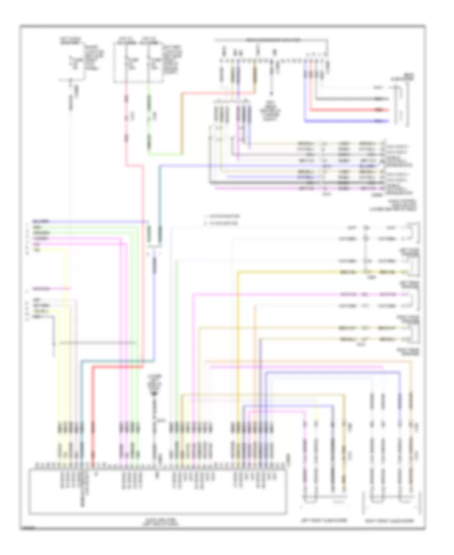 https://portal-diagnostov.com/license.html
Automotive Electricians Portal FZCO
Automotive Electricians Portal FZCO
https://portal-diagnostov.com/license.html
https://portal-diagnostov.com/license.html
Automotive Electricians Portal FZCO
Automotive Electricians Portal FZCOList of elements for Premium Radio Wiring Diagram (3 of 3) for Ford Mustang GT 2013:
- (lower left side of dash) g202
- Audio amplifier (left end of dash)
- Audio control module (acm) (lower center of dash)
- Aux aud 2 +
- Aux aud 2 -
- Battery junction box (bjb) (right side of engine compt)
- C210
- C211
- C213
- C214
- C2280b
- C237
- C2385a
- C2385b
- C260
- C290b
- C4109a
- C4109b
- Clip detect main/aux3 enable/ lf spkr-
- Cme31
- Dme51
- Fuse 30a
- Fuse 5a
- G401 (rear center of luggage compt)
- Gd115
- Gnd
- Hot at all times
- Hot in run or start
- Inp+
- Inp-
- Left door speaker
- Left front subwoofer
- Left rear speaker
- Lf spkr+
- Lf spkr-
- Lr spkr+
- Lr spkr-
- Mute
- Nca
- Out+
- Out-
- Rear subwoofer
- Rear subwoofer amplifier
- Red
- Rf spkr+
- Rf spkr-
- Right door speaker
- Right front subwoofer
- Right rear speaker
- Rme07
- Rme09
- Rme10
- Rme12
- Rme17
- Rme18
- Rme51
- Rme60
- Rme61
- Rme74
- Rme75
- Rme76
- Rme77
- Rr spkr+
- Rr spkr-
- S210
- Sbb33
- Shield aux aud 2 enable/mute
- Smart junction box (sjb) (right kick panel)
- Sme51
- Vbatt
- Vme07
- Vme09
- Vme10
- Vme12
- Vme17
- Vme18
- Vme51
- Vme60
- Vme61
- Vme74
- Vme75
- Vme76
- Vme77
- W/ navigation
- W/o navigation
SYNC Radio Wiring Diagram (1 of 2) for Ford Mustang GT 2013
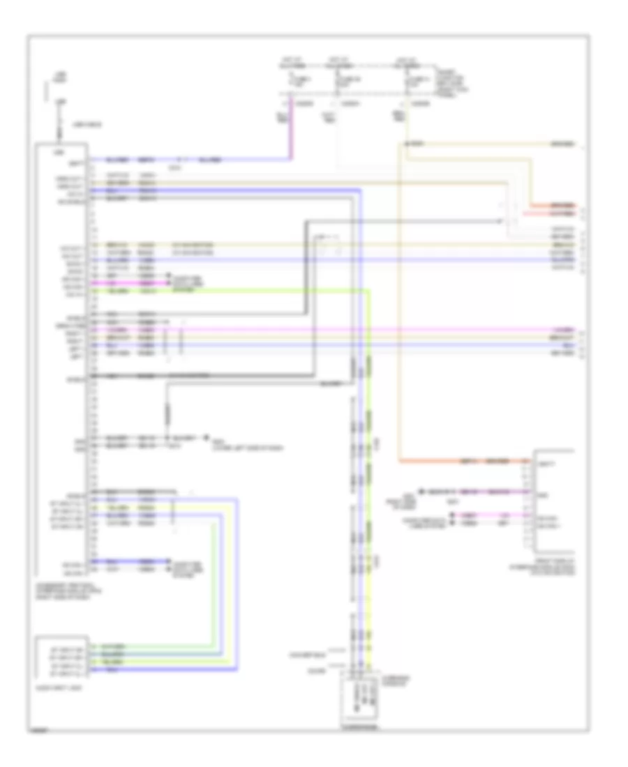 https://portal-diagnostov.com/license.html
Automotive Electricians Portal FZCO
Automotive Electricians Portal FZCO
https://portal-diagnostov.com/license.html
https://portal-diagnostov.com/license.html
Automotive Electricians Portal FZCO
Automotive Electricians Portal FZCOList of elements for SYNC Radio Wiring Diagram (1 of 2) for Ford Mustang GT 2013:
- (w/ navigation)
- Accessory protocol interface module (apim) (right side of dash)
- Audio input jack
- C210
- C2280a
- C2280b
- C2280d
- C913
- Computer data lines system
- Convertible
- Coupe
- Dme45
- Dme52
- Dmm13
- Dmm23
- Dmn14
- Drain wire
- Front display interface module (fdim) (w/o navigation)
- Fuse 14 10a
- Fuse 3 15a
- Fuse 39 20a
- G201 (right side of dash)
- G202 (lower left side of dash)
- Gd115
- Gd116
- Gnd
- Hot at all times
- Hs can +
- Hs can -
- Left +
- Left -
- Mic in +
- Mic in -
- Mic out +
- Mic out -
- Mic shield
- Mic shield -
- Microphone
- Mono out +
- Mono out -
- Ms can +
- Ms can -
- Nca
- Overhead console
- Right +
- Right -
- Rme45
- Rme46
- Rme52
- Rme53
- Rme54
- Rmm13
- Rmm23
- Rmn14
- S201
- S210
- S232
- Sbp03
- Sbp14
- Shield
- Smart junction box (sjb) (right kick panel)
- St input 2l +
- St input 2l -
- St input 2r +
- St input 2r -
- Swc2 +
- Swc2 -
- Usb
- Usb cable
- Usb port
- Vbatt
- Vdb04
- Vdb05
- Vdb06
- Vdb07
- Vme45
- Vme46
- Vme52
- Vme53
- Vme54
- Vmm13
- Vmm23
- Vmn14
SYNC Radio Wiring Diagram (2 of 2) for Ford Mustang GT 2013
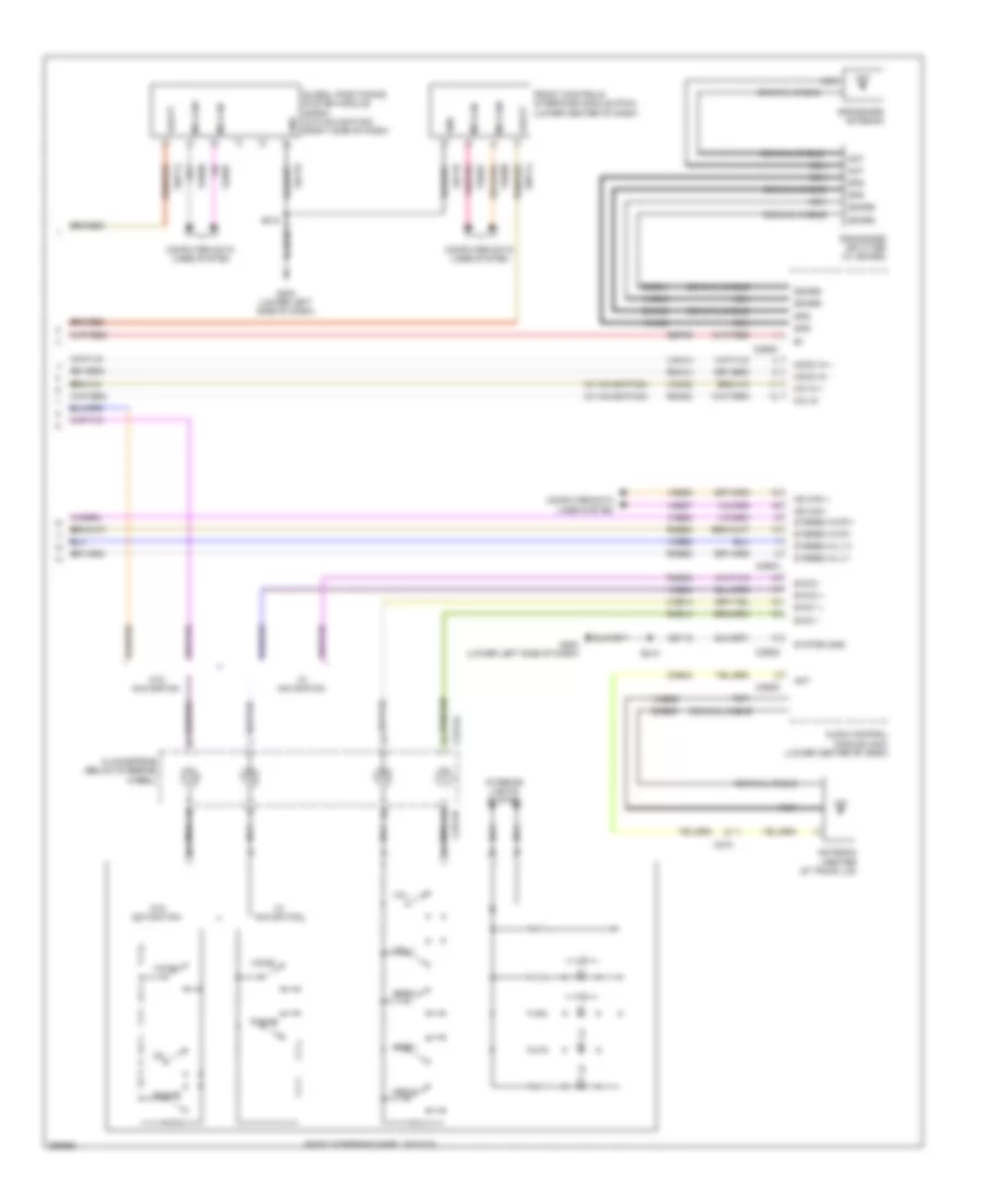 https://portal-diagnostov.com/license.html
Automotive Electricians Portal FZCO
Automotive Electricians Portal FZCO
https://portal-diagnostov.com/license.html
https://portal-diagnostov.com/license.html
Automotive Electricians Portal FZCO
Automotive Electricians Portal FZCOList of elements for SYNC Radio Wiring Diagram (2 of 2) for Ford Mustang GT 2013:
- (w/ navigation)
- Ant
- Antenna (center of trunk lid)
- Audio control module (acm) (lower center of dash)
- C210
- C2274a
- C2274b
- C290a
- C290d
- Clockspring (below steering wheel)
- Cme44
- Coaxial cable
- Computer data lines system
- Dme35
- Dme41
- Dmn03
- Front controls interface module (fcim) (lower center of dash)
- G202 (lower left side of dash)
- Gd115
- Global positioning system module (gpsm) (w/o navigation) (right side of dash)
- Gnd
- Gps
- Gps/sdars antenna
- Gps/sdars splitter (w/ sdars)
- Interior lights system
- Media
- Mic in +
- Mic in -
- Mono in +
- Mono in -
- Ms can +
- Ms can -
- Ms can+
- Ms can-
- Nca
- Phone
- Right steering wheel switch
- Rme14
- Rme52
- Rme53
- Rme54
- Rmm23
- Rmn14
- S210
- Sbp14
- Sbp39
- Sdars
- Seek +
- Seek -
- Stereo in lt+
- Stereo in lt-
- Stereo in rt+
- Stereo in rt-
- Swc1 +
- Swc1 -
- Swc2 +
- Swc2 -
- System gnd
- Vbatt
- Vdb06
- Vdb07
- Vme14
- Vme35
- Vme43
- Vme52
- Vme53
- Vme54
- Vmm23
- Vmn03
- Vmn14
- Voice
- Vol +
- Vol -
- W/ navigation
- W/o navigation
SHIFT INTERLOCK
Shift Interlock Wiring Diagram for Ford Mustang GT 2013
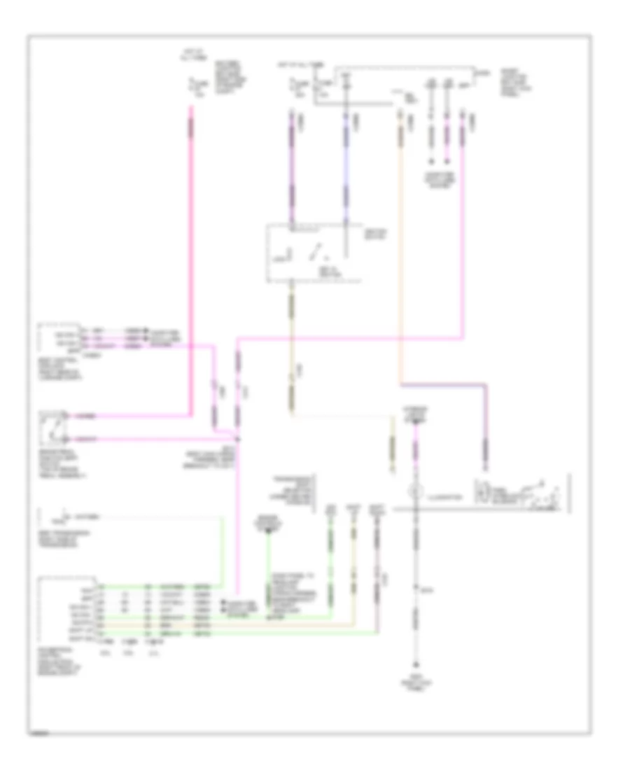 https://portal-diagnostov.com/license.html
Automotive Electricians Portal FZCO
Automotive Electricians Portal FZCO
https://portal-diagnostov.com/license.html
https://portal-diagnostov.com/license.html
Automotive Electricians Portal FZCO
Automotive Electricians Portal FZCOList of elements for Shift Interlock Wiring Diagram for Ford Mustang GT 2013:
- (dash panel to headlamp junction wiring harness, near breakout to right headlamp) s199
- (right kick panel)
- 3.7l
- 5.0l
- 5.8l
- 6r80 transmission (right side of transmission)
- All times
- Battery junction box (bjb) (right side of engine compt)
- Body control module b (right rear of luggage compt)
- Bpp
- Bpp c4368a
- Brake pedal position (bpp) switch (top of brake pedal assembly)
- Bsi (fet)
- C1381b
- C175b
- C210
- C211
- C219
- C2280a
- C2280b
- C2280c
- C265
- Ccb08
- Cet35
- Cet42
- Cet60
- Computer data lines system
- Engine controls system
- Fuse 10a
- Fuse 20a
- G203
- Hot at
- Hot at all times
- Hs can +
- Hs can -
- Ignition switch
- Illumination
- Interior lights system
- Key in ign
- Key in ignition
- Lock
- Micro
- Ms can +
- Ms can -
- Ms can+
- Ms can-
- Park interlock solenoid
- Powertrain control module (pcm) (right front of engine compt)
- Re405
- S213 (body main wiring harness, near breakout to c211)
- S319
- Shift dn
- Shift down
- Shift up
- Sig rtn
- Smart junction box (sjb) (right kick panel)
- Tr-p
- Transmission shift selector (under center console)
- Vdb04
- Vdb05
- Vdb06
- Vdb07
STARTING/CHARGING
Charging Wiring Diagram for Ford Mustang GT 2013
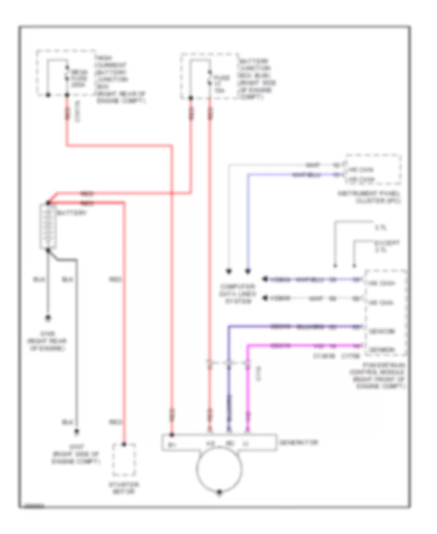 https://portal-diagnostov.com/license.html
Automotive Electricians Portal FZCO
Automotive Electricians Portal FZCO
https://portal-diagnostov.com/license.html
https://portal-diagnostov.com/license.html
Automotive Electricians Portal FZCO
Automotive Electricians Portal FZCOList of elements for Charging Wiring Diagram for Ford Mustang GT 2013:
- 3.7l
- Battery
- Battery junction box (bjb) (right side of engine compt)
- C110
- C1381b
- C1617a
- C175b
- Cdc10
- Cdc15
- Computer data lines system
- Except 3.7l
- Fuse 10a
- G106 (right rear of engine)
- G107 (right side of engine compt)
- Gencom
- Generator
- Genmon
- High current battery junction box (right rear of engine compt)
- Hs can+
- Hs can-
- Instrument panel cluster (ipc)
- Mega fuse 200a
- Powertrain control module (right front of engine compt)
- Red
- Starter motor
- Vdb04
- Vdb05
Starting Wiring Diagram for Ford Mustang GT 2013
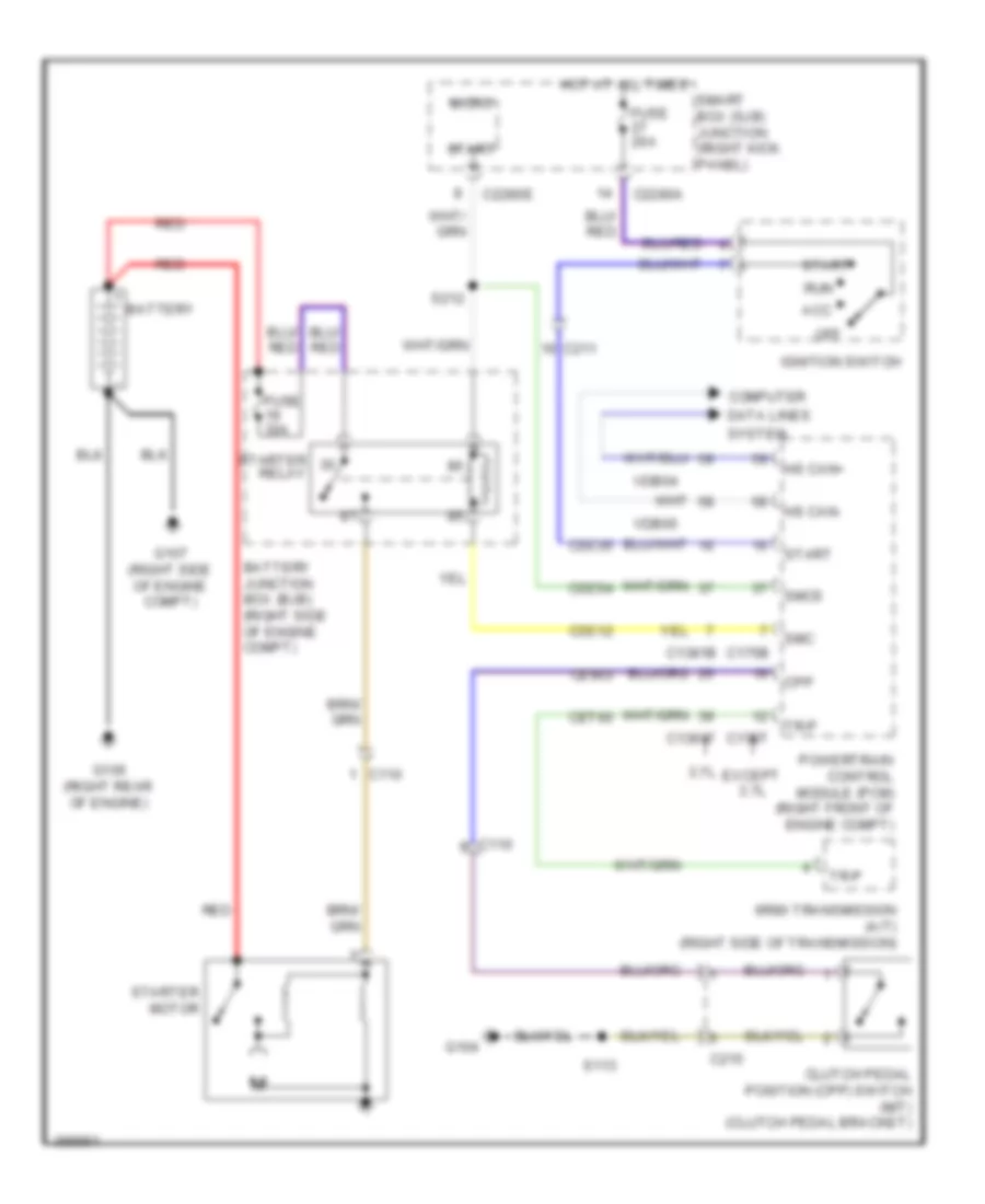 https://portal-diagnostov.com/license.html
Automotive Electricians Portal FZCO
Automotive Electricians Portal FZCO
https://portal-diagnostov.com/license.html
https://portal-diagnostov.com/license.html
Automotive Electricians Portal FZCO
Automotive Electricians Portal FZCOList of elements for Starting Wiring Diagram for Ford Mustang GT 2013:
- 3.7l
- 6r80 transmission (a/t) (right side of transmission)
- Acc
- Battery
- Battery junction box (bjb) (right side of engine compt)
- C110
- C1381b
- C1381t
- C175b
- C175t
- C211
- C215
- C2280a
- C2280e
- Cdc12
- Cdc35
- Cdc54
- Ce903
- Cet60
- Clutch pedal position (cpp) switch (m/t) (clutch pedal bracket)
- Computer
- Cpp
- Data lines
- Except 3.7l
- Fuse 20a
- Fuse 30a
- G104
- G106 (right rear of engine)
- G107 (right side of engine compt)
- Hot at all times
- Hs can+
- Hs can-
- Ignition switch
- Micro
- Off
- Powertrain control module (pcm) (right front of engine compt)
- Red
- Run
- S113
- S212
- Smart box (sjb) junction (right kick panel)
- Smc
- Smcs
- Start
- Starter motor
- Starter relay
- System
- Tr-p
- Vdb04
- Vdb05
SUPPLEMENTAL RESTRAINTS
Supplemental Restraints Wiring Diagram (1 of 2) for Ford Mustang GT 2013
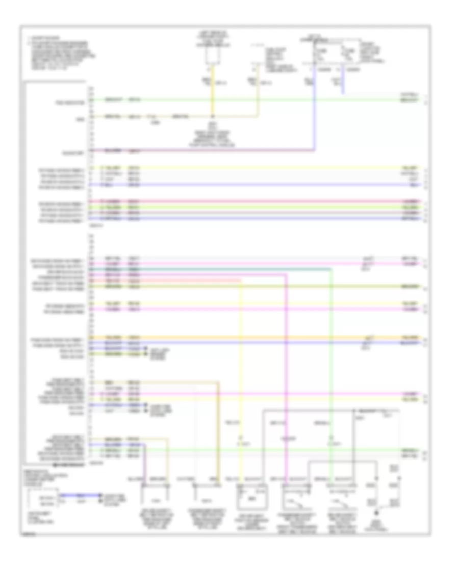 https://portal-diagnostov.com/license.html
Automotive Electricians Portal FZCO
Automotive Electricians Portal FZCO
https://portal-diagnostov.com/license.html
https://portal-diagnostov.com/license.html
Automotive Electricians Portal FZCO
Automotive Electricians Portal FZCOList of elements for Supplemental Restraints Wiring Diagram (1 of 2) for Ford Mustang GT 2013:
- (left rear of luggage compt) fuel pump control module
- Anti-lock brakes system
- B10
- B11
- B11 c213
- C2041a
- C2041b
- C214
- C2280b
- C2280d
- C260
- C300
- C311
- Case ground
- Cbp31
- Computer data lines system
- Cr101
- Cr102
- Cr103
- Cr104
- Cr105
- Cr106
- Cr113
- Cr116
- Cr120
- Cr122
- Cr201
- Cr203
- Driver buckle sw
- Driver safety belt buckle switch (driver's seat belt buckle)
- Driver safety belt retractor pretensioner (base of left "b" pillar)
- Driver seat position sensor (under driver's seat)
- Drvr seat belt pretensioner rtn drvr seat belt pretensioner feed
- Drvr seat track sn feed
- Drvr side air bag feed
- Drvr side air bag rtn
- Drvr side crash sn feed 1
- Drvr side crash sn rtn 1
- Ens
- Fr crash sens feed
- Fr crash sens rtn
- Fr drvr air bag feed 1
- Fr drvr air bag feed 2
- Fr drvr air bag rtn 1
- Fr drvr air bag rtn 2
- Fr pass air bag feed 1
- Fr pass air bag feed 2
- Fr pass air bag rtn 1
- Fr pass air bag rtn 2
- Fuel pump control module 2 (5.8l) (right side of luggage compt)
- Fuse 10a
- Fuse 7.5a
- G205 (right kick panel)
- Hot in start or run
- Hs can +
- Hs can -
- Hs can+
- Hs can-
- Instrument panel cluster (ipc)
- Pad indicator
- Pass seat belt pretensioner rtn pass seat belt pretensioner feed pass side air bag feed
- Pass seat track sn feed
- Pass side air bag rtn
- Pass side crash sn feed 1
- Pass side crash sn rtn 1
- Passenger buckle sw
- Passenger safety belt buckle switch (front passenger's seat belt buckle)
- Passenger safety belt retractor pretensioner (base of right "b" pillar)
- Pin shorting bars engaged when module connector is disconnected from harness: (shorting bars are connected between following pins: c2041a: 1-2, 3-4, 7-8 & 9-10, c2041b: 1-2 & 11-12)
- Rcs hs can+
- Rcs hs can-
- Restraints control module (rcm) (under center console)
- Rr101
- Rr102
- Rr103
- Rr104
- Rr105
- Rr106
- Rr120
- Rr122
- Rr129
- Rr131
- Rr132
- Run/start
- S220
- S301
- S325
- S401 (5.8l) (body main wiring harness, near breakout to fuel pump control module)
- Shorting bar
- Smart junction box (sjb) (right kick panel)
- Vca23
- Vca24
- Vdb04
- Vdb05
- Vr213
- Vr215
- Vr216
- Vr217
- Vr218
Supplemental Restraints Wiring Diagram (2 of 2) for Ford Mustang GT 2013
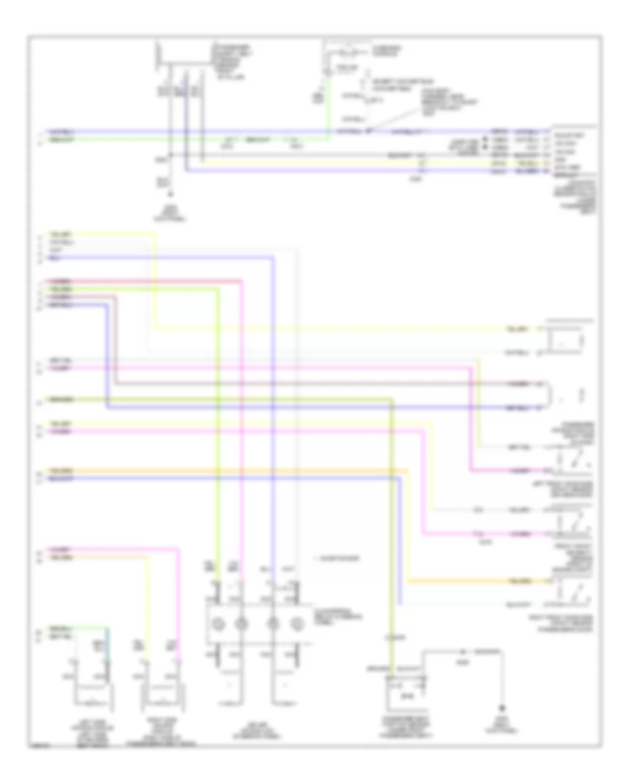 https://portal-diagnostov.com/license.html
Automotive Electricians Portal FZCO
Automotive Electricians Portal FZCO
https://portal-diagnostov.com/license.html
https://portal-diagnostov.com/license.html
Automotive Electricians Portal FZCO
Automotive Electricians Portal FZCOList of elements for Supplemental Restraints Wiring Diagram (2 of 2) for Ford Mustang GT 2013:
- (convertible)
- (except convertible)
- (main body harness, near breakout to smart junction box) s237
- Bts out
- Bts vref
- C210
- C219
- C300
- C913
- Cbp46
- Clockspring (below steering wheel)
- Computer data lines system
- Driver air bag unit (steering wheel)
- Front impact severity sensor (front of engine compt)
- G205 (right kick panel)
- Gd138
- Gnd
- Hs can+
- Hs can-
- Left front door side impact sensor (driver's door)
- Left side air bag module (left side of driver's seat back)
- Lr142
- Nca
- Occupant classification sensor module (under passenger's seat)
- Overhead console
- Pad ind
- Passenger air bag module (right side of dash)
- Passenger safety belt tension sensor (right "b" pillar)
- Passenger seat position sensor (under front passenger's seat)
- Right front door side impact sensor (passenger's door)
- Right side air bag module (right side of passenger's seat back)
- Run/start
- S220
- S325
- Shorting bar
- Vdb04
- Vdb05
- Vr210
TRANSMISSION
3.7L
3.7L, Transmission Wiring Diagram (1 of 2) for Ford Mustang GT 2013
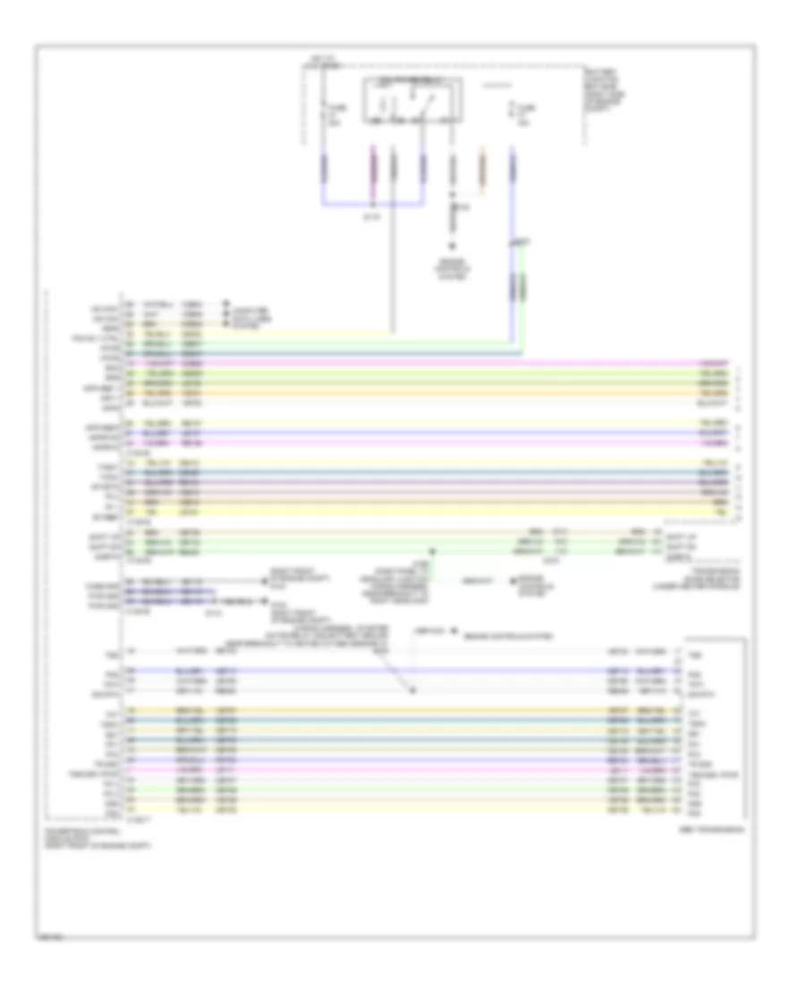 https://portal-diagnostov.com/license.html
Automotive Electricians Portal FZCO
Automotive Electricians Portal FZCO
https://portal-diagnostov.com/license.html
https://portal-diagnostov.com/license.html
Automotive Electricians Portal FZCO
Automotive Electricians Portal FZCOList of elements for 3.7L, Transmission Wiring Diagram (1 of 2) for Ford Mustang GT 2013:
- (right front of engine compt) g103
- (wiring harness - starter motor relay and battery ground near breakout to heated oxygen sensor 12) s138
- 15a
- 30a
- 6r80 transmission
- App 1
- App2
- Apprtn
- Apprtn2
- Appvref 1
- Appvref2
- Battery junction box (bjb) (right side of engine compt)
- Boo
- Bps
- C1381b
- C1381e
- C1381t
- C219
- Case gnd
- Cbb47
- Ccb08
- Cdb08
- Ce302
- Ce412
- Ce426
- Ces09
- Cet05
- Cet06
- Cet07
- Cet08
- Cet09
- Cet10
- Cet18
- Cet25
- Cet35
- Cet42
- Cet60
- Computer data lines system
- Engine controls system
- Etcref
- Etcrtn
- Feps
- Fuse
- G102 (right front of engine compt)
- Gd119
- Hot at all times
- Hs can+
- Hs can-
- Le111
- Le134
- Le136
- Le137
- Oss
- Pc 2
- Pc 3
- Pc1
- Pc2
- Pc3
- Pc4
- Pc5
- Pc6
- Pcm power relay
- Pcm rly ctrl
- Powertrain control module (pcm) (right front of engine compt)
- Pwr gnd
- Re134
- Re136
- Re137
- Re405
- Re406
- Ret24
- Ret33
- S115
- S116
- S123
- S199 (dash panel to headlamp junction wiring harness, near breakout to right headlamp)
- Shift dn
- Shift up
- Sig rtn
- Sigrtn
- Ss1
- Tacm+
- Tacm-
- Tft
- Tp 1
- Tp 2
- Tr gnd
- Tr p
- Transmission shife selector (under center console)
- Tspc
- Tss
- Tss/oss vpwr
- Vdb04
- Vdb05
- Ve701
- Ve702
- Ve818
- Ve819
- Vet26
- Vet27
- Vet33
- Vpwr
3.7L, Transmission Wiring Diagram (2 of 2) for Ford Mustang GT 2013
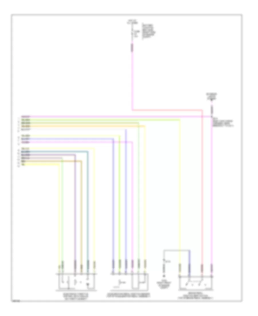 https://portal-diagnostov.com/license.html
Automotive Electricians Portal FZCO
Automotive Electricians Portal FZCO
https://portal-diagnostov.com/license.html
https://portal-diagnostov.com/license.html
Automotive Electricians Portal FZCO
Automotive Electricians Portal FZCOList of elements for 3.7L, Transmission Wiring Diagram (2 of 2) for Ford Mustang GT 2013:
- 10a
- Accelerator pedal position sensor (top of accelerator pedal assembly)
- Battery junction box (bjb) (right side of engine compt)
- Brake pedal position (bpp) switch (top of brake pedal assembly)
- Electronic throttle control (etc) module (on throttle body)
- Exterior lights system
- Fuse
- G102 (right front of engine compt)
- Hot at all times
- S115
- S213 (body main wiring harness, near breakout to c211)
5.0L
5.0L, Transmission Wiring Diagram (1 of 2) for Ford Mustang GT 2013
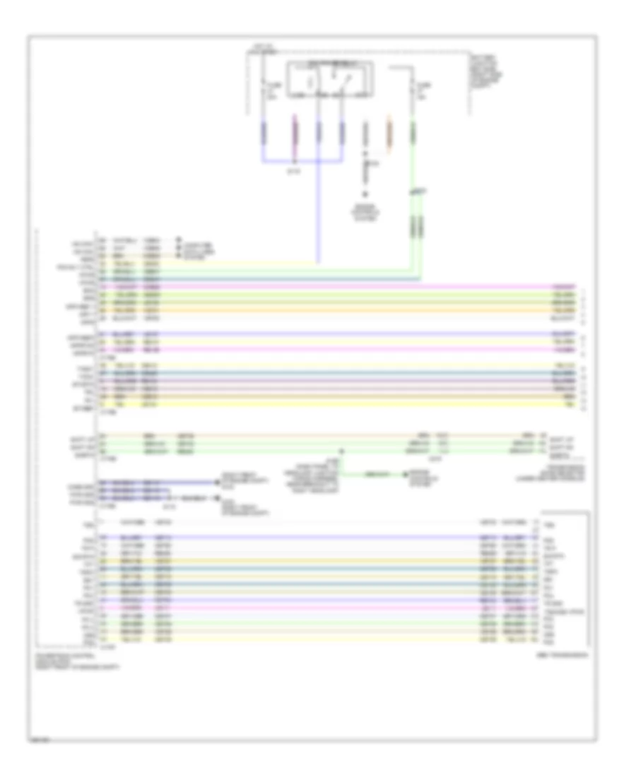 https://portal-diagnostov.com/license.html
Automotive Electricians Portal FZCO
Automotive Electricians Portal FZCO
https://portal-diagnostov.com/license.html
https://portal-diagnostov.com/license.html
Automotive Electricians Portal FZCO
Automotive Electricians Portal FZCOList of elements for 5.0L, Transmission Wiring Diagram (1 of 2) for Ford Mustang GT 2013:
- (right front of engine compt) g103
- 15a
- 30a
- 6r80 transmission
- App 1
- App2
- Apprtn
- Apprtn2
- Appvref 1
- Appvref2
- Battery junction box (bjb) (right side of engine compt)
- Boo
- Bps
- C175b
- C175e
- C175t
- C219
- Case gnd
- Cbb47
- Ccb08
- Cdb08
- Ce302
- Ce412
- Ce426
- Ces09
- Cet05
- Cet06
- Cet07
- Cet08
- Cet09
- Cet10
- Cet18
- Cet25
- Cet35
- Cet42
- Cet60
- Computer data lines system
- Engine controls system
- Etcref
- Etcrtn
- Feps
- Fuse
- G102 (right front of engine compt)
- Gd119
- Hot at all times
- Hs can+
- Hs can-
- Le111
- Le134
- Le136
- Le137
- Oss
- Pc 2
- Pc 3
- Pc1
- Pc2
- Pc3
- Pc4
- Pc5
- Pc6
- Pcm power relay
- Pcm rly ctrl
- Powertrain control module (pcm) (right front of engine compt)
- Pwr gnd
- Re134
- Re136
- Re137
- Re405
- Re406
- Ret24
- S115
- S116
- S123
- S199 (dash panel to headlamp junction wiring harness, near breakout to right headlamp)
- Shift dn
- Shift up
- Sig rtn
- Sigrtn
- Ss1
- Tacm+
- Tacm-
- Tft
- Tp1
- Tp2
- Tr gnd
- Tr p
- Transmission shife selector (under center console)
- Tspc
- Tss
- Tss/oss vpwr
- Vdb04
- Vdb05
- Ve701
- Ve702
- Ve818
- Ve819
- Vet26
- Vet27
- Vet33
- Vpwr
5.0L, Transmission Wiring Diagram (2 of 2) for Ford Mustang GT 2013
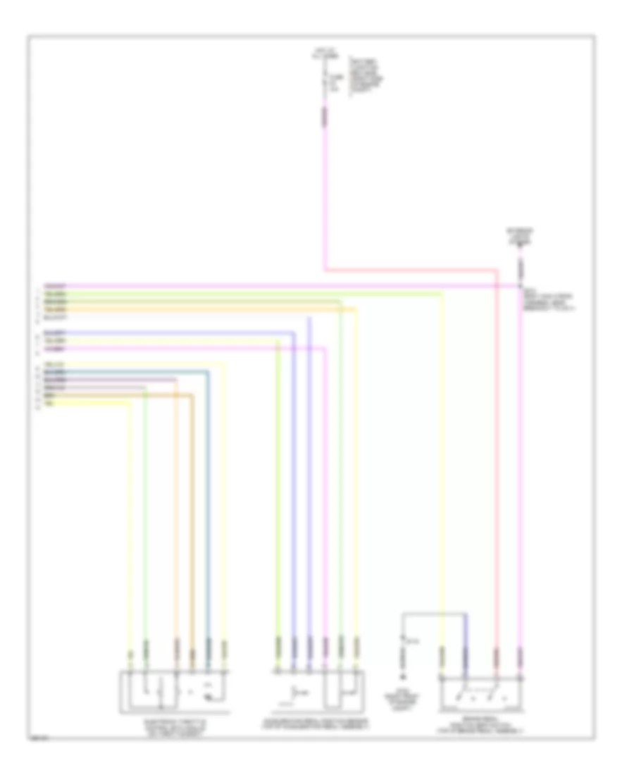 https://portal-diagnostov.com/license.html
Automotive Electricians Portal FZCO
Automotive Electricians Portal FZCO
https://portal-diagnostov.com/license.html
https://portal-diagnostov.com/license.html
Automotive Electricians Portal FZCO
Automotive Electricians Portal FZCOList of elements for 5.0L, Transmission Wiring Diagram (2 of 2) for Ford Mustang GT 2013:
- 10a
- Accelerator pedal position sensor (top of accelerator pedal assembly)
- Battery junction box (bjb) (right side of engine compt)
- Brake pedal position (bpp) switch (top of brake pedal assembly)
- Electronic throttle control (etc) module (on throttle body)
- Exterior lights system
- Fuse
- G102 (right front of engine compt)
- Hot at all times
- S115
- S213 (body main wiring harness, near breakout to c211)
TRUNK, TAILGATE, FUEL DOOR
Trunk Release Wiring Diagram for Ford Mustang GT 2013
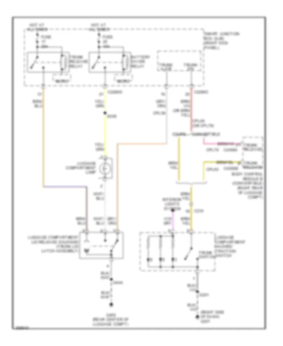 https://portal-diagnostov.com/license.html
Automotive Electricians Portal FZCO
Automotive Electricians Portal FZCO
https://portal-diagnostov.com/license.html
https://portal-diagnostov.com/license.html
Automotive Electricians Portal FZCO
Automotive Electricians Portal FZCOList of elements for Trunk Release Wiring Diagram for Ford Mustang GT 2013:
- (right side of dash) g201
- Battery saver relay
- Body control module b (convertible) (right rear of luggage compt)
- C210
- C2280c
- C2280d
- C4368a
- C4368b
- Convertible
- Coupe
- Cpl58
- Cpl60
- Cpl60 (or cpl79)
- Cpl79
- Fuse 10a
- Fuse 20a
- G402 (rear center of luggage compt)
- Hot at all times
- Interior lights system
- Luggage compartment hazard/ traction switch
- Luggage compartment lamp
- Luggage compartment lid release solenoid (trunk lid latch assembly)
- Micro
- Release
- S201
- S209
- S404
- Smart junction box (sjb) (right kick panel)
- Trunk
- Trunk ajar
- Trunk release
- Trunk release relay
- Trunk sw
- Trunk switch
WARNING SYSTEMS
Chime Wiring Diagram for Ford Mustang GT 2013
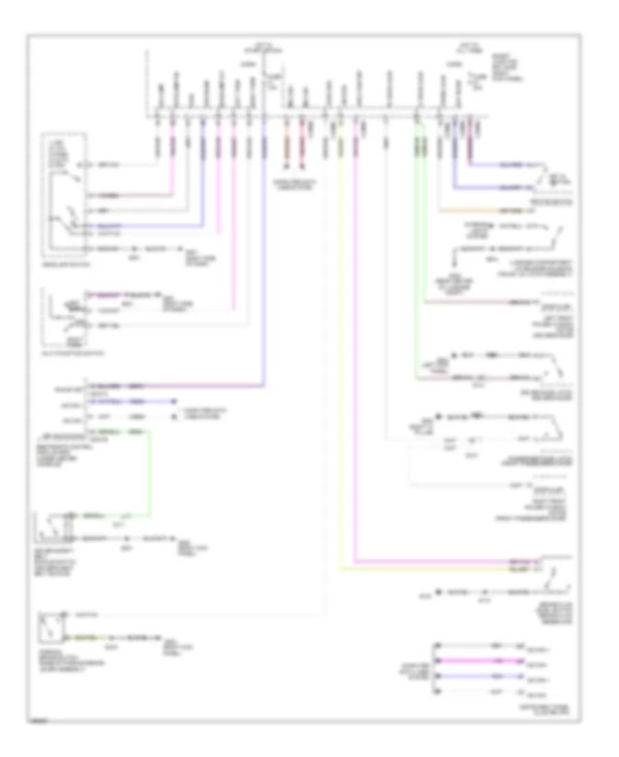 https://portal-diagnostov.com/license.html
Automotive Electricians Portal FZCO
Automotive Electricians Portal FZCO
https://portal-diagnostov.com/license.html
https://portal-diagnostov.com/license.html
Automotive Electricians Portal FZCO
Automotive Electricians Portal FZCOList of elements for Chime Wiring Diagram for Ford Mustang GT 2013:
- 1) off 2) low 3) park 4) auto 5) fog
- Autolamp on
- Brake fluid level switch (brake fluid reservoir)
- Brk fluid sw
- C2041a
- C2041b
- C213
- C214
- C2280a
- C2280b
- C2280c
- C2280f
- C311
- Cbp31
- Computer data lines system
- Cr201
- Door ajar
- Driver door latch (driver's door)
- Driver safety belt buckle switch (driver's seat belt buckle)
- Drv buckle sw
- Fog lamp
- Fuse 10a
- Fuse 20a
- G104
- G201 (right side of dash)
- G203 (right "a" pillar)
- G203 (right kick panel)
- G204 (left kick panel)
- G205 (right kick panel)
- G402 (rear center of luggage compt)
- Headlamp off
- Headlamp switch
- Hot at all times
- Hot in start or run
- Hs can +
- Hs can -
- Ignition switch
- Instrument panel cluster (ipc)
- Interior lights system
- Key in ign
- Key in ignition
- Left front power window motor (driver's door)
- Left turn
- Lf door ajar
- Low beam
- Luggage compartment lid release solenoid (trunk lid latch assembly)
- Micro
- Ms can +
- Ms can -
- Multi-function switch
- Off
- Park
- Park brk
- Parking brake switch (base of parking brake lever assembly)
- Passenger door latch (front passenger's door)
- Restraints control module (rcm) (under center console)
- Rf door ajar
- Right front power window motor (front passenger's door)
- Right turn
- Run/start
- S113
- S201
- S301
- S319
- S404
- S503
- S602
- Smart junction box (sjb) (right kick panel)
- Sw rtn
- Trunk ajar
- Vdb04
- Vdb05
Tire Pressure Monitoring Wiring Diagram for Ford Mustang GT 2013
 https://portal-diagnostov.com/license.html
Automotive Electricians Portal FZCO
Automotive Electricians Portal FZCO
https://portal-diagnostov.com/license.html
https://portal-diagnostov.com/license.html
Automotive Electricians Portal FZCO
Automotive Electricians Portal FZCOList of elements for Tire Pressure Monitoring Wiring Diagram for Ford Mustang GT 2013:
- (not used)
- Battery junction box (bjb) (right side of engine compt)
- C2280b
- C2280f
- C2280g
- Computer data lines system
- Ctrl
- Fuse 10a
- Fuse 80a
- G203 (right kick panel)
- Gnd
- Hot at all times
- Hs can +
- Hs can -
- Instrument panel cluster (ipc)
- Internal tmps/ rke antenna
- Left front tire pressure sensor
- Left rear tire pressure sensor
- Micro
- Ms can +
- Ms can -
- Pwr gnd
- Red
- Right front tire pressure sensor
- Right rear tire pressure sensor
- S114
- S319
- Smart junction box (sjb) (right kick panel)
- Tpms (fet)
- Tpms receiver
- Vbatt
WIPER/WASHER
Wiper/Washer Wiring Diagram for Ford Mustang GT 2013
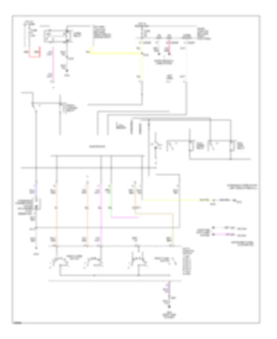 https://portal-diagnostov.com/license.html
Automotive Electricians Portal FZCO
Automotive Electricians Portal FZCO
https://portal-diagnostov.com/license.html
https://portal-diagnostov.com/license.html
Automotive Electricians Portal FZCO
Automotive Electricians Portal FZCOList of elements for Wiper/Washer Wiring Diagram for Ford Mustang GT 2013:
- (not used)
- 1) off 2) int 1 3) int 2 4) int 3 5) int 4 6) int 5 7) low 8) high
- Battery junction box (bjb) (right side of engine compt)
- C211
- C2280b
- C2280e
- C2280f
- Computer data lines system
- Electronics
- Front wash switch
- Front washer relay
- Front wiper switch
- Fuse 30a
- Fuse 5a
- G100
- G104
- G201 (right side of dash)
- Hall sensor
- Hi/lo speed relay
- Hot at all times
- Hot in run or acc
- Instrument panel cluster (ipc)
- Ms can+
- Ms can-
- Multi- function switch
- Park/sense
- Red
- Run/ park relay
- Run/park
- S100
- S112
- S130
- S201
- Smart junction box (sjb) (right kick panel)
- Windshield washer pump motor (on washer fluid reservoir)
- Windshield wiper motor (left side of firewall)
- Wiper relay
- Wiper status

 Čeština
 Dansk
Dansk Deutsch
 Ελληνικά
 English
 English
 Español
 Suomi
Suomi Français
 Français
 עברית
עברית Hrvatski
 Magyar
 Italiano
 한국어
한국어 Nederlands
 Polski
 Português
 Português
 Română
 Русский
 Slovenčina
 Slovenščina
 Svenska
 Türkçe
 中文 (中国)
