AIR CONDITIONING
Automatic A/C Wiring Diagram for Ford Pickup F150 2002
 https://portal-diagnostov.com/license.html
Automotive Electricians Portal FZCO
Automotive Electricians Portal FZCO
https://portal-diagnostov.com/license.html
https://portal-diagnostov.com/license.html
Automotive Electricians Portal FZCO
Automotive Electricians Portal FZCO
List of elements for Automatic A/C Wiring Diagram for Ford Pickup F150 2002:
- (under dash near steering column) s292
- A/c clutch cycling pressure switch (right rear of engine compt)
- A/c clutch relay
- A/c clutch solenoid
- A/c compressor clutch diode
- A/c high pressure switch (right side of engine compt)
- A/c rly gnd
- Ambient air temperature sensor (right side of engine compt)
- Auxiliary relay box 4 (behind center of dash)
- Battery junction box (bjb) (left side of engine compt)
- Blend door ctrl
- Blower +
- Blower -
- Blower motor relay
- Blower rly gnd
- C228a
- C228b
- C270a
- C270b
- C271a
- C271b
- Central junction box (under left side of dash)
- Data link connector (under center of dash)
- Electronic automatic temperature control (eatc) module (behind center of dash)
- Front blower motor
- Front blower motor speed controller (behind right side of dash)
- Fuse 105 40a
- Fuse 13 15a
- Fuse 2 5a
- Fuse 23 15a
- Fuse 24 10a
- G102 (right rear of engine compt)
- G200 (right front footwell)
- Gnd
- Hot at all times
- Hot in run and start
- Illum
- In-vehicle temperature sensor (behind right side of dash)
- Instrument cluster)
- Interior lights system
- Powertrain control module (right side of engine compt)
- S102 (right rear of engine compt)
- S155 (left rear of engine compt)
- S200 (near glove box)
- S236 (behind instru- ment cluster)
- S286 (behind right side of dash)
- S290 (behind right side of instrument cluster)
- S291 (under dash near steering column)
- Scp+
- Scp-
- Sensor +
- Sig rtn
- Sig rtn -
- Speed ctrl
- Sunload sen inpt
- Sunload sensor (top right side of dash)
- Temp input
- Temperature blend door actuator (behind center of dash)
- Vbatt
- Veh temp input
- Vpwr
- Vref
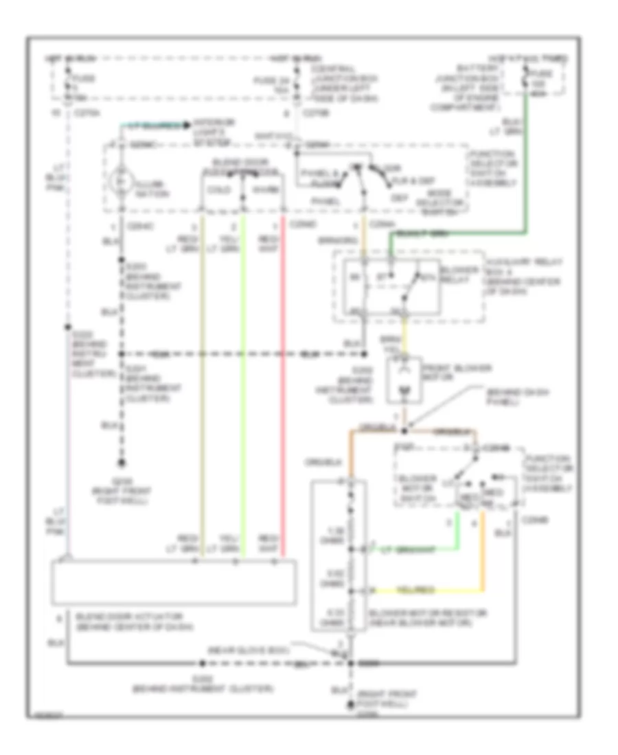
Heater Wiring Diagram for Ford Pickup F150 2002
 https://portal-diagnostov.com/license.html
Automotive Electricians Portal FZCO
Automotive Electricians Portal FZCO
https://portal-diagnostov.com/license.html
https://portal-diagnostov.com/license.html
Automotive Electricians Portal FZCO
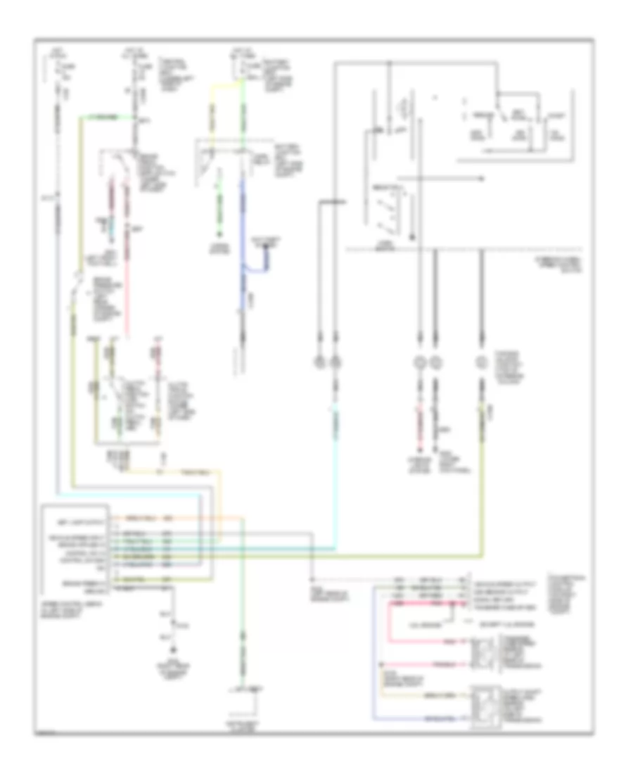
Automotive Electricians Portal FZCOList of elements for Heater Wiring Diagram for Ford Pickup F150 2002:
- (behind dash panel)
- (near glove box)
- (right front footwell) g200
- 0.33 ohms
- 0.62 ohms
- 1.38 ohms
- 87a
- Auxiliary relay box 4 (behind center of dash)
- Battery junction box (in left side of engine compartment)
- Blend door actuator (behind center of dash)
- Blend door potentiometer
- Blower motor resistor (near blower motor)
- Blower motor switch
- Blower relay
- C270a
- C270b
- C294a
- C294b
- C294c
- C294d
- Central junction box (under left side of dash)
- Cold
- Def
- Floor
- Flr & def
- Front blower motor
- Function selector switch assembly
- Fuse 15a
- Fuse 24 10a
- Fuse 40a
- G200 (right front footwell)
- Hot at all times
- Hot in run
- Illumi- nation
- Interior lights system
- Med hi
- Med lo
- Mode selector switch
- Off
- Panel
- Panel &
- S125
- S200
- S201 (behind instrument cluster)
- S202 (behind instrument cluster)
- S203 (behind instrument cluster)
- S222 (behind instru- ment cluster)
- Warm
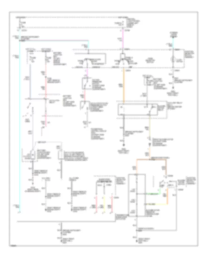
Manual A/C Wiring Diagram for Ford Pickup F150 2002
 https://portal-diagnostov.com/license.html
Automotive Electricians Portal FZCO
Automotive Electricians Portal FZCO
https://portal-diagnostov.com/license.html
https://portal-diagnostov.com/license.html
Automotive Electricians Portal FZCO
Automotive Electricians Portal FZCOList of elements for Manual A/C Wiring Diagram for Ford Pickup F150 2002:
- (behind dash panel) s125
- (behind instrument cluster) s202
- (behind instrument cluster) s222
- (near glove box) s200
- (not used)
- (right front footwell) g200
- (right rear of engine compt) g102
- (right rear of engine compt) s102
- (right rear of engine compt) s153
- 0.33 ohms
- 0.62 ohms
- 1.38 ohms
- 5.4l (ngv) & 4.2l
- 87a
- A/c
- A/c clutch cycling pressure switch (in right rear of engine compartment)
- A/c clutch diode
- A/c clutch relay
- A/c clutch solenoid (4.2l: in left front of engine compartment) (4.6l & 5.4l: in right front of engine compartment)
- A/c high pressure switch (in right side of engine compartment)
- All other models
- Auxiliary relay box 4 (behind center of dash)
- Battery junction box (in left side of engine compartment)
- Blend door potentiometer
- Blower motor relay
- Blower motor resistor (near blower motor)
- Blower motor switch
- C270a
- C270b
- C294a
- C294b
- C294c
- C294d
- Central junction box (under left side of dash)
- Cold
- Def
- Defrost
- Floor
- Flr & def
- Flr/defrost
- Front blower motor (on right side of engine compartment)
- Function selector switch assembly
- Fuse 15a
- Fuse 24 10a
- Fuse 40a
- G102 (right rear of engine compt)
- G200 (right front footwell)
- Hot at all times
- Hot in run
- Hot in run or start
- Illumi- nation
- Interior lights system
- Max a/c
- Med hi
- Med lo
- Mode selector switch
- Off panel/floor
- Panel
- Panel & off floor
- Powertrain control module (pcm) (on right side of engine compartment)
- S155 (left rear of engine compt)
- S203 (behind instrument cluster)
- Temperature blend door actuator
- Warm
ANTI-LOCK BRAKES
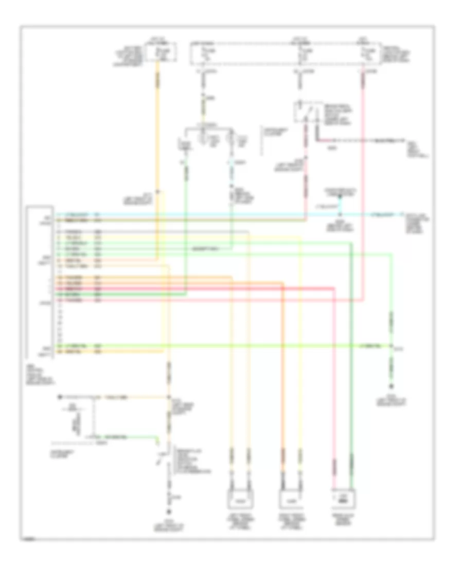
Anti-lock Brake Wiring Diagrams for Ford Pickup F150 2002
 https://portal-diagnostov.com/license.html
Automotive Electricians Portal FZCO
Automotive Electricians Portal FZCO
https://portal-diagnostov.com/license.html
https://portal-diagnostov.com/license.html
Automotive Electricians Portal FZCO
Automotive Electricians Portal FZCOList of elements for Anti-lock Brake Wiring Diagrams for Ford Pickup F150 2002:
- (except ngv)
- 4 x 4 high ind
- Abs control module (left side of engine compt)
- Anti- lock ind
- Battery junction box (in left side of engine compartment)
- Bias ckt
- Brake fluid level indicator switch (on brake fluid reservoir)
- Brake pedal position (bpp) switch (under left side of dash)
- C220a
- C270a
- C270b
- Central junction box (behind left side of dash)
- Computer data lines system
- Data link connector (under center of dash)
- Fuse 10a
- Fuse 50a
- Fuse 5a
- G104 (left front of engine compt)
- G201 (left front footwell)
- Gnd
- Hot at all times
- Hot in run
- Instrument cluster
- Iso
- Left front wheel speed sensor (at wheel)
- Nca
- Ohm
- Processor micro-
- Rear axle speed sensor
- Red/pnk
- Right front wheel speed sensor (at wheel)
- S106
- S160 (left rear of engine compt)
- S170 (left rear of engine compt)
- S171 (left front of engine compt)
- S172
- S208
- S229 (behind left side of dash)
- S232 (behind left side of dash)
- S265
- Tan/red
- Vbatt
- Vpwr
ANTI-THEFT
Forced Entry Wiring Diagram, with Analog Keypad for Ford Pickup F150 2002
 https://portal-diagnostov.com/license.html
Automotive Electricians Portal FZCO
Automotive Electricians Portal FZCO
https://portal-diagnostov.com/license.html
https://portal-diagnostov.com/license.html
Automotive Electricians Portal FZCO
Automotive Electricians Portal FZCOList of elements for Forced Entry Wiring Diagram, with Analog Keypad for Ford Pickup F150 2002:
- (behind right side of dash)
- (in left rocker panel) (w/ super- crew) s273
- (in passenger door) s601
- (in passenger door) s602
- (in right front footwell) (w/ super- crew)
- (lower right kick panel)
- (lower right kick panel) g200
- (under center of dash) data link connector
- (w/ super crew)
- (w/ supercrew)
- (w/o super crew)
- 1/2
- 3/4
- 5/6
- 7/8
- 9/0
- Ajar in
- Ajar out
- Antenna
- Autolamps
- Battery
- Battery junction box (left side of engine compt)
- Bpp sw in
- Brake pedal position switch (under left side of dash)
- C201a
- C201b
- C270b
- C274a
- C274b
- Central junction box (under left side of dash)
- Central security module (behind left side of dash)
- Diagnostic
- Door ajar
- Doors lock
- Doors unlock
- Driver side rear door ajar switch
- Driver unlock
- Exterior lights system
- Fuse 15a
- Fuse 20a
- Fuse 5a
- G200
- G200 (lower right kick panel)
- G201 (lower left kick panel)
- Generic electronic module (gem) (behind left side of dash)
- Ground
- Horn
- Horns system
- Hot at all times
- Hot in run or start
- Ignition
- Illum entry
- Illum in
- Interior lights
- Keypad illum
- Keypad switch assembly (if equipped)
- Left front door ajar switch
- Left front door lock actuator
- Left power door lock switch
- Left rear door lock actuator (w/ supercrew)
- Lft
- Lock
- Lock in/out
- Nca
- Passenger side rear door ajar switch
- Red
- Reverse
- Right front door ajar switch
- Right front door lock actuator
- Right power door lock switch
- Right rear door lock actuator (w/ supercrew)
- S203
- S204
- S208
- S225
- S229
- S234
- S235 (behind right side of dash)
- S260
- S261
- S297 (behind left side of instru- ment cluster)
- S500
- S501
- S600
- S774
- S864
- Unlk
- Unlock in/out
- W/ super- crew
- W/o super- crew
Forced Entry Wiring Diagram, with Digital Keypad for Ford Pickup F150 2002
 https://portal-diagnostov.com/license.html
Automotive Electricians Portal FZCO
Automotive Electricians Portal FZCO
https://portal-diagnostov.com/license.html
https://portal-diagnostov.com/license.html
Automotive Electricians Portal FZCO
Automotive Electricians Portal FZCOList of elements for Forced Entry Wiring Diagram, with Digital Keypad for Ford Pickup F150 2002:
- (behind right side of dash)
- (in left rocker panel) (w/ super- crew) s273
- (in passenger door) s601
- (in passenger door) s602
- (in right front footwell) (w/ super- crew)
- (lower right kick panel)
- (lower right kick panel) g200
- (under center of dash) data link connector
- (w/ super crew)
- (w/ supercrew)
- (w/o super crew)
- 1/2
- 3/4
- 5/6
- 7/8
- 9/0
- Ajar in
- Ajar out
- Antenna
- Autolamps
- Battery
- Battery junction box (left side of engine compt)
- Bpp sw in
- Brake pedal position switch (under left side of dash)
- C201a
- C201b
- C270b
- C274a
- C274b
- Central junction box (under left side of dash)
- Central security module (behind left side of dash)
- Diagnostic
- Digital keypad
- Door ajar
- Doors lock
- Doors unlock
- Driver side rear door ajar switch
- Driver unlock
- Exterior lights system
- Fuse 15a
- Fuse 20a
- Fuse 5a
- G200
- G200 (lower right kick panel)
- G201 (lower left kick panel)
- Generic electronic module (gem) (behind left side of dash)
- Ground
- Horn
- Horns system
- Hot at all times
- Hot in run or start
- Ignition
- Illum entry
- Illum in
- Interior lights
- Keypad illum
- Keypad switch assembly (if equipped)
- Left front door ajar switch
- Left front door lock actuator
- Left power door lock switch
- Left rear door lock actuator (w/ supercrew)
- Lft
- Lock
- Lock in/out
- Nca
- Passenger side rear door ajar switch
- Red
- Reverse
- Right front door ajar switch
- Right front door lock actuator
- Right power door lock switch
- Right rear door lock actuator (w/ supercrew)
- S203
- S204
- S208
- S225
- S229
- S234
- S235 (behind right side of dash)
- S260
- S261
- S297 (behind left side of instru- ment cluster)
- S500
- S501
- S600
- S774
- S864
- Unlk
- Unlock in/out
- W/ super- crew
- W/o super- crew
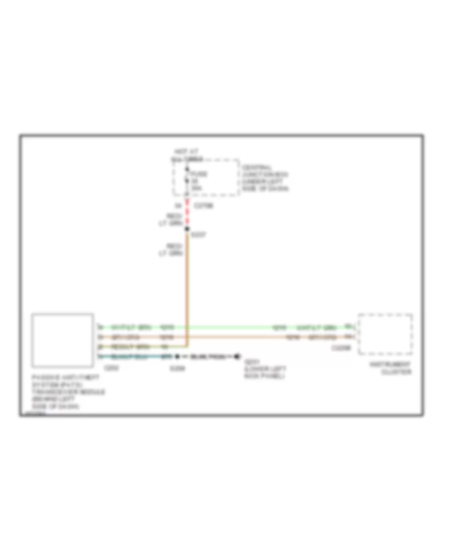
Passive Anti-theft Wiring Diagram for Ford Pickup F150 2002
 https://portal-diagnostov.com/license.html
Automotive Electricians Portal FZCO
Automotive Electricians Portal FZCO
https://portal-diagnostov.com/license.html
https://portal-diagnostov.com/license.html
Automotive Electricians Portal FZCO
Automotive Electricians Portal FZCOList of elements for Passive Anti-theft Wiring Diagram for Ford Pickup F150 2002:
- C220b
- C252
- C270b
- Central junction box (under left side of dash)
- Fuse 30a
- G201 (lower left kick panel)
- Hot at all times
- Instrument cluster
- Passive anti-theft system (pats) transceiver module (behind left side of dash)
- S208
- S237
BODY COMPUTER
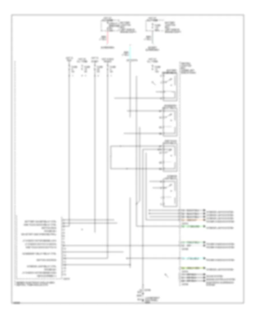
Body Computer Wiring Diagrams (1 of 2) for Ford Pickup F150 2002
 https://portal-diagnostov.com/license.html
Automotive Electricians Portal FZCO
Automotive Electricians Portal FZCO
https://portal-diagnostov.com/license.html
https://portal-diagnostov.com/license.html
Automotive Electricians Portal FZCO
Automotive Electricians Portal FZCOList of elements for Body Computer Wiring Diagrams (1 of 2) for Ford Pickup F150 2002:
- (lower right kick panel) g200
- 87a
- Accessory delay relay
- Accessory delay relay ctrl
- Battery junction box (left side of engine compt)
- Battery saver relay
- Battery saver relay ctrl
- C201d
- C270a
- C270b
- Central junction box (under left side of dash)
- Circuit breaker 30a
- Electronic suspension system
- Engine controls system
- Except supercrew
- Fuse 15a
- Fuse 30a
- Fuse 5a
- Generic electronic module (gem)/ central timer module (ctm)
- Hot at all times
- Hot in
- Hot in run
- Hot in run or acc
- Ign (start) gnd (park/neutral)
- Ignition (acc/run)
- Ignition (run)
- Interior lamp relay
- Interior lamp relay ctrl
- Interior lights system
- Lf window motor sense (high)
- Lf window motor sense (low)
- Lf window switch in (down)
- One touch down relay
- One touch down relay ctrl
- One touch down switch in
- Power (b+)
- Power windows system
- S205
- Sound system
- Start
- Supercrew
- Vehicle speed (+)
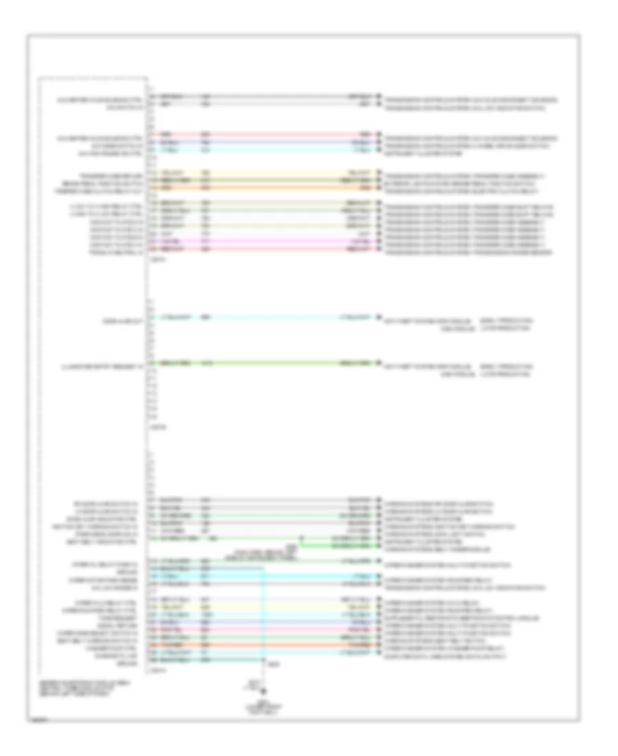
Body Computer Wiring Diagrams (2 of 2) for Ford Pickup F150 2002
 https://portal-diagnostov.com/license.html
Automotive Electricians Portal FZCO
Automotive Electricians Portal FZCO
https://portal-diagnostov.com/license.html
https://portal-diagnostov.com/license.html
Automotive Electricians Portal FZCO
Automotive Electricians Portal FZCOList of elements for Body Computer Wiring Diagrams (2 of 2) for Ford Pickup F150 2002:
- (csm module)
- (early production)
- (late production)
- (park/headlamps on) in
- 4 high to 4 low relay ctrl
- 4 low to 4 high relay ctrl
- 4x2 center axle solenoid ctrl
- 4x4 center axle solenoid ctrl
- 4x4 high range ind ctrl
- 4x4 low range in
- 4x4 mode switch in
- 4x4 switch in
- Anti-theft system (rap module)
- Brake pedal position switch
- C201a
- C201b
- C201c
- Computer data lines system (datalink pin 7)
- Contact plate a in
- Contact plate b in
- Contact plate c in
- Contact plate d in
- Diagnostic link
- Door ajar indicator ctrl
- Door ajar out
- Exterior lights system (brake pedal position switch)
- G201 (lower front footwell)
- Generic electronic module (gem)/ central timer module (ctm) (behind left side of dash)
- Ground
- Ignition key warning switch in
- Illuminated entry request in
- Instrument cluster system
- Interval delay/wash in
- Lf door ajar switch in
- Red
- Rf door ajar switch in
- S208
- S268 (main harn, behind left side of instrument panel)
- Seat belt indicator ctrl
- Seat belt warning switch in
- Signal return
- Tan/red
- Tone request
- Trans in neutral in
- Transfer case return
- Transmission controls system (4 wheel drive mode switch)
- Transmission controls system (4x2 axle disconnect solenoid)
- Transmission controls system (4x4 axle disconnect solenoid)
- Transmission controls system (4x4 low indicator switch)
- Transmission controls system (electric clutch relay)
- Transmission controls system (transfer case assembly)
- Transmission controls system (transfer case shift relays)
- Transmission controls system (transmission range sensor)
- Trnsfer case clutch relay out
- Warning systems (belt minder module)
- Warning systems (ignition key warning switch)
- Warning systems (lf door ajar switch)
- Warning systems (main light switch)
- Warning systems (rf door ajar switch)
- Warning systems (seat belt switch)
- Washer pump ctrl
- Wiper hi/lo relay ctrl
- Wiper mode select switch in
- Wiper motor park sense
- Wiper run/park relay ctrl
- Wiper/washer system (hi/lo relay)
- Wiper/washer system (multi-function switch)
- Wiper/washer system (run/park relay)
- Wiper/washer system (washer pump relay)
COMPUTER DATA LINES
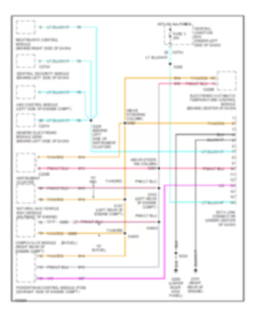
Computer Data Lines, with Supercrew Cab for Ford Pickup F150 2002
 https://portal-diagnostov.com/license.html
Automotive Electricians Portal FZCO
Automotive Electricians Portal FZCO
https://portal-diagnostov.com/license.html
https://portal-diagnostov.com/license.html
Automotive Electricians Portal FZCO
Automotive Electricians Portal FZCOList of elements for Computer Data Lines, with Supercrew Cab for Ford Pickup F150 2002:
- (bi-fuel)
- (near steer- ing column) s291
- (near steering column) s292
- Abs control module (left side of engine compt)
- C201a
- C220b
- C228b
- C270a
- C274a
- Central junction box (under left side of dash)
- Central security module (behind left side of dash)
- Compuvalve module (right rear of engine compt)
- Data link connector (under center of dash)
- Electronic automatic temperature control module (behind center of dash)
- Fuse 3 20a
- G085
- G086
- G101 (right rear of engine)
- G200 (lower right kick panel)
- Generic electronic module (gem) (behind left side of dash)
- Hot at all times
- Instrument cluster
- Natural gas vehicle (ngv) module (on front of engine)
- Powertrain control module (pcm) (on right side of engine compt)
- Restraints control module (behind right side of dash)
- S156 (left rear of engine compt)
- S157 (left rear of engine compt)
- S202
- S229 (behind left side of instrument cluster)
- S289
- S4003
- S4004
- W/ bi-fuel
- W/ ngv
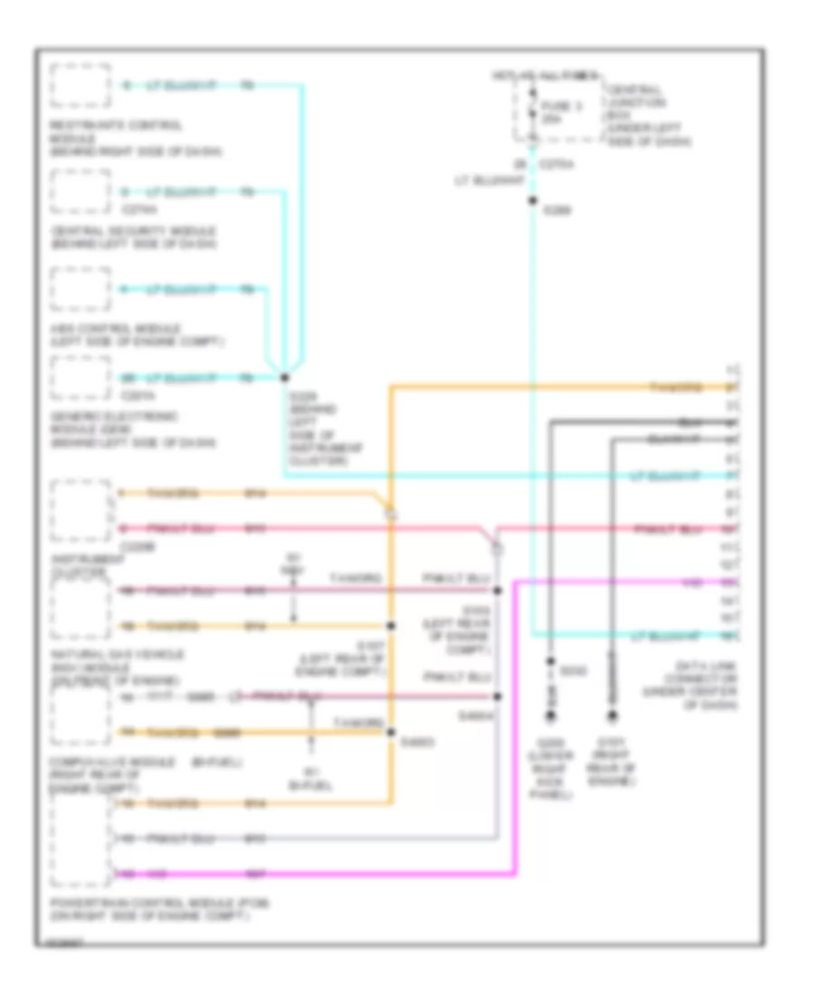
Computer Data Lines, without Supercrew Cab for Ford Pickup F150 2002
 https://portal-diagnostov.com/license.html
Automotive Electricians Portal FZCO
Automotive Electricians Portal FZCO
https://portal-diagnostov.com/license.html
https://portal-diagnostov.com/license.html
Automotive Electricians Portal FZCO
Automotive Electricians Portal FZCOList of elements for Computer Data Lines, without Supercrew Cab for Ford Pickup F150 2002:
- (bi-fuel)
- Abs control module (left side of engine compt)
- C201a
- C220b
- C270a
- C274a
- Central junction box (under left side of dash)
- Central security module (behind left side of dash)
- Compuvalve module (right rear of engine compt)
- Data link connector (under center of dash)
- Fuse 3 20a
- G085
- G086
- G101 (right rear of engine)
- G200 (lower right kick panel)
- Generic electronic module (gem) (behind left side of dash)
- Hot at all times
- Instrument cluster
- Natural gas vehicle (ngv) module (on front of engine)
- Powertrain control module (pcm) (on right side of engine compt)
- Restraints control module (behind right side of dash)
- S156 (left rear of engine compt)
- S157 (left rear of engine compt)
- S202
- S229 (behind left side of instrument cluster)
- S289
- S4003
- S4004
- W/ bi-fuel
- W/ ngv
COOLING FAN
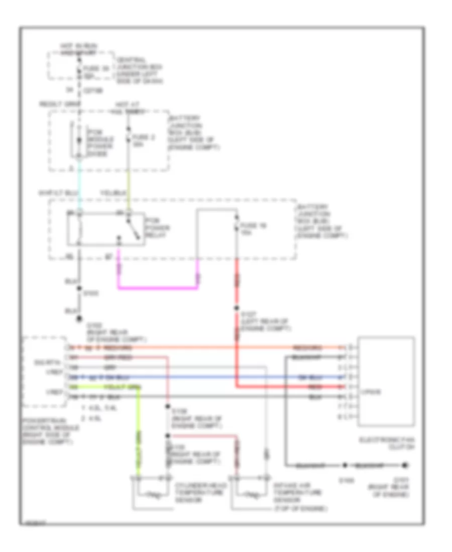
Cooling Fan Wiring Diagram for Ford Pickup F150 2002
 https://portal-diagnostov.com/license.html
Automotive Electricians Portal FZCO
Automotive Electricians Portal FZCO
https://portal-diagnostov.com/license.html
https://portal-diagnostov.com/license.html
Automotive Electricians Portal FZCO
Automotive Electricians Portal FZCOList of elements for Cooling Fan Wiring Diagram for Ford Pickup F150 2002:
- (top of engine)
- 4.2l, 5.4l
- 4.6l
- Battery junction box (bjb) (left side of engine compt)
- C270b
- Central junction box (under left side of dash)
- Cylinder head temperature sensor
- Electronic fan clutch
- Fuse 18 15a
- Fuse 2 30a
- Fuse 30 30a
- G101 (right rear of engine)
- G102 (right rear of engine compt)
- Hot at all times
- Hot in run and start
- Intake air temperature sensor
- Pcm module power diode
- Pcm power relay
- Powertrain control module (right side of engine compt)
- Red
- S100
- S105
- S127 (left rear of engine compt) red
- S135 (right rear of engine compt)
- S138 (right rear of engine compt)
- Sig rtn -
- Vpwr
- Vref
CRUISE CONTROL
Cruise Control Wiring Diagram for Ford Pickup F150 2002
 https://portal-diagnostov.com/license.html
Automotive Electricians Portal FZCO
Automotive Electricians Portal FZCO
https://portal-diagnostov.com/license.html
https://portal-diagnostov.com/license.html
Automotive Electricians Portal FZCO
Automotive Electricians Portal FZCOList of elements for Cruise Control Wiring Diagram for Ford Pickup F150 2002:
- (4.2l engine)
- (except 4.2l engine)
- A/t
- Accel
- Air bag sliding contact (top of steering column)
- Anti-theft system
- Battery junction box (left side of engine compt)
- Brake pedal position (bpp) switch (under left side of dash)
- Brake press in
- Brake pressure switch (left rear corner of engine compt)
- C140
- C218b
- C220a
- C242
- C270b
- Central junction box (under left side of dash)
- Cluster
- Clutch pedal position (ccp) switch (on clutch pedal arm)
- Clutch triple function switch jumper (left side of dash)
- Coast
- Control sw gnd
- Control sw in
- Esof
- Fuse 15a
- Fuse 20a
- Fuse 5a
- G102 (right rear of engine compt)
- G200 (lower right kick panel)
- G201 (left front footwell)
- Ground
- Horn relay
- Horn switch
- Horns system
- Hot at all times
- Hot in run
- Ign
- Instrument
- Interior lights system
- M/t
- Nca
- Off
- Ohms
- Oss sensor output
- Output shaft speed (oss) sensor (on left side of transmission)
- Pnk
- Powertrain control module (on right side of engine compt)
- Resistor a
- Resume
- S102
- S112
- S138 (right rear of engine compt)
- S143 (left rear of engine compt)
- S208
- S274
- S297
- Set lamp output
- Set/
- Signal return
- Speed control servo (in left side of engine compt)
- Steering wheel/ speed control switch
- Transfer case sp sen
- Transfer case speed sensor (at left rear of transmission)
- Vehicle speed input
- Vehicle speed output
ENGINE PERFORMANCE
4.2L
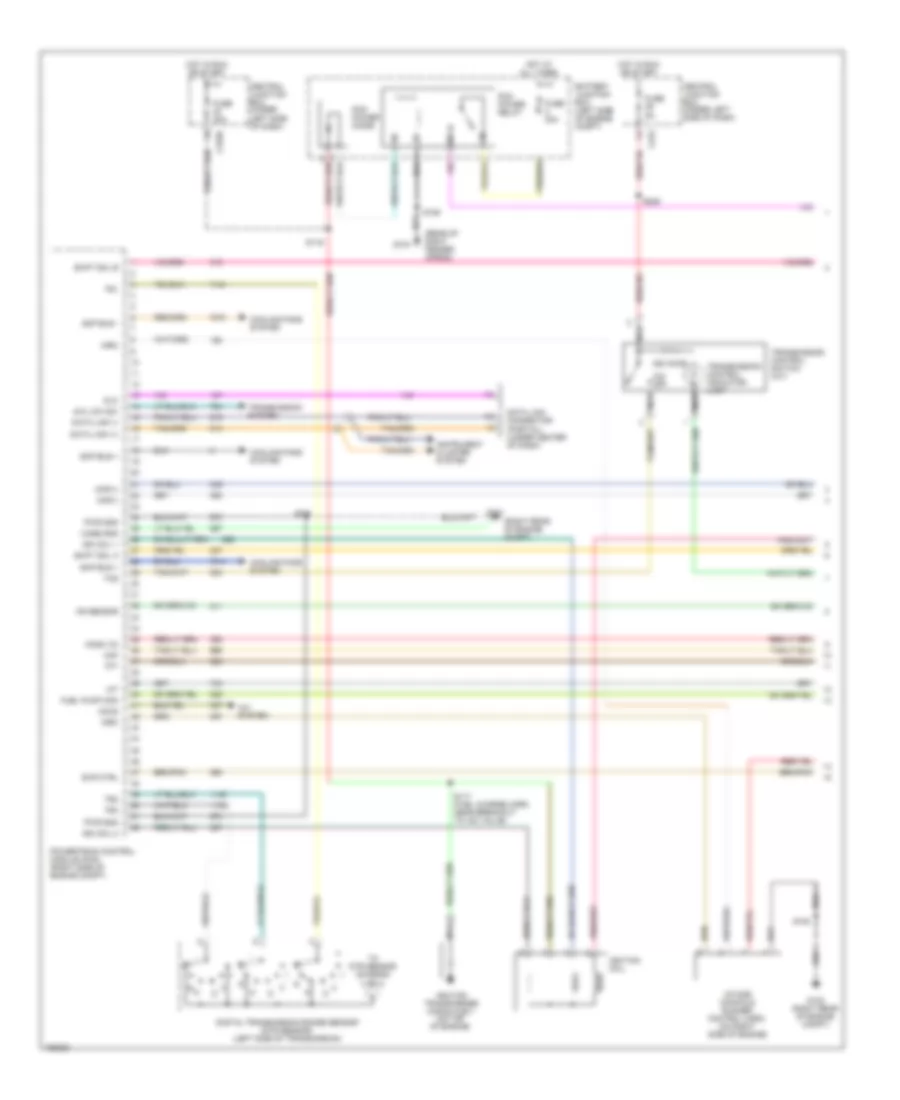
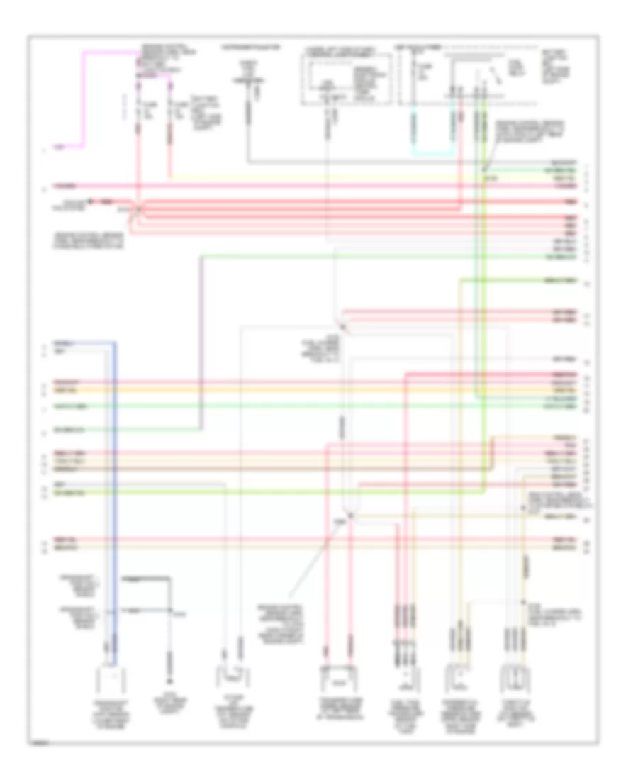
4.2L, Engine Performance Wiring Diagrams (1 of 4) for Ford Pickup F150 2002
 https://portal-diagnostov.com/license.html
Automotive Electricians Portal FZCO
Automotive Electricians Portal FZCO
https://portal-diagnostov.com/license.html
https://portal-diagnostov.com/license.html
Automotive Electricians Portal FZCO
Automotive Electricians Portal FZCOList of elements for 4.2L, Engine Performance Wiring Diagrams (1 of 4) for Ford Pickup F150 2002:
- (rear of right fender apron)
- (right rear of engine compt)
- 4x4 low sw
- 820 ohms
- A/c system
- Accs
- Battery junction box (left side of engine compt)
- C243
- C270b
- Case gnd
- Central junction box (under left side of dash)
- Ckp(+)
- Ckp(-)
- Cooling fans system
- Data link (+)
- Data link (-)
- Data link connector (partial) (under center of dash)
- Digital transmission range sensor (dtr sensor) (left side of transmission)
- Dlc
- Evr ctrl
- Fuel pump mon
- Fuse 30a
- Fuse 5a
- G101
- G102 (right rear of engine compt)
- G104
- Ho2s (12)
- Hot at all times
- Hot in run or start
- Iat
- Ign coil 1
- Ign coil 2
- Ignition coil
- Ignition transformer capacitor 1 (on top of engine)
- Imrc
- Instrument cluster system
- Intake manifold runner control (imrc) (on right side of engine)
- Ks sensor
- Maf
- Nca
- O/d off
- Pcm power diode
- Pcm power relay
- Powertrain control module (pcm) (right side of engine compt)
- Pwr gnd
- R n
- S100
- S106
- S116
- S117 (fuel charge harn, near breakout to iac valve)
- S153
- S225
- Scp bus +
- Scp bus -
- Shift sol a
- Shift sol b
- Tcs
- Tft
- To dtr sensor (diagram 4 of 4)
- Tr1
- Tr2
- Tr4
- Transmission control indicator lamp
- Transmission control switch (a/t)
- Transmission system
4.2L, Engine Performance Wiring Diagrams (2 of 4) for Ford Pickup F150 2002
 https://portal-diagnostov.com/license.html
Automotive Electricians Portal FZCO
Automotive Electricians Portal FZCO
https://portal-diagnostov.com/license.html
https://portal-diagnostov.com/license.html
Automotive Electricians Portal FZCO
Automotive Electricians Portal FZCOList of elements for 4.2L, Engine Performance Wiring Diagrams (2 of 4) for Ford Pickup F150 2002:
- (eng control sens harn, near breakout to starter mtr relay) s137
- (engine control sensor harn, near breakout to 4-pin conn in right rear corner of engine compt)
- (engine control sensor harn, near breakout to 40-pin conn in left rear of engine compt)
- (engine control sensor harn, near breakout to windshield wiper motor)
- (under left side of dash) central junction box
- Battery junction box (left side of engine compt)
- C201d
- C220a
- Check fuel cap indicator
- Cooling fan system
- Crankshaft position (ckp) sensor (lower front of engine)
- Crankshaft position sensor shield
- Differential pressure feedback egr (dpfe) sensor (right side of engine)
- Fuel pump relay
- Fuel tank pressure transducer sensor (at fuel tank)
- Fuse 15a
- Fuse 20a
- G123 (right rear of engine compt)
- Generic electronic module/ central timer module
- Hot at all times
- Instrument cluster
- Intake air temperature (iat) sensor (on intake manifold)
- Nca
- Pnk
- Red
- Red/pnk
- S100
- S127
- S135 (fuel charge harn, near breakout to fuel inj 4)
- S136 (fuel charge harn, near breakout to fuel inj 2)
- S138
- S139
- Throttle position (tp) sensor (on throttle body)
- Transfer case speed sensor (at left rear of transmission)
- Vss input
4.2L, Engine Performance Wiring Diagrams (3 of 4) for Ford Pickup F150 2002
 https://portal-diagnostov.com/license.html
Automotive Electricians Portal FZCO
Automotive Electricians Portal FZCO
https://portal-diagnostov.com/license.html
https://portal-diagnostov.com/license.html
Automotive Electricians Portal FZCO
Automotive Electricians Portal FZCOList of elements for 4.2L, Engine Performance Wiring Diagrams (3 of 4) for Ford Pickup F150 2002:
- (back-up lamp sw to rear lamp feed harn, at breakout to 38-pin conn in right rear of engine compt)
- (engine control sensor harn, near breakout to 40-pin conn, left rear corner of engine compt)
- (fuel charge harn, near breakout to 16-pin conn, right rear of eng compt)
- (fuel charge harn, near top of cylinder 2)
- (inside fuel pump assembly) fuel pump module
- (left front of engine compt)
- (under right side of dash) inertia fuel shut-off switch
- 4r70w transmission
- Egr vacuum regulator solenoid (right side of engine)
- Electronic pressure control solenoid
- Evap canister purge
- Fuel injectors
- G104
- Idle air control valve (on left side of intake manifold)
- Instrument cluster system
- Nca
- Output shaft speed (oss) sensor (left side of transmission)
- Pnk
- Red
- Red/pnk
- S129
- S131 (fuel charge harn, near breakout to imrc)
- S140
- S141 (back-up lamp sw to rear lamp feed harn, in breakout to 38-pin conn conn in right rear of engine compt)
- S154
- S155
- S400
- Shift solenoids
- Ssa
- Ssb
- Tan
- Torque converter clutch solenoid
- Transmission fluid temperature sensor
- Valve (left rear corner of engine compt)
4.2L, Engine Performance Wiring Diagrams (4 of 4) for Ford Pickup F150 2002
 https://portal-diagnostov.com/license.html
Automotive Electricians Portal FZCO
Automotive Electricians Portal FZCO
https://portal-diagnostov.com/license.html
https://portal-diagnostov.com/license.html
Automotive Electricians Portal FZCO
Automotive Electricians Portal FZCOList of elements for 4.2L, Engine Performance Wiring Diagrams (4 of 4) for Ford Pickup F150 2002:
- (engine control sensor harn, near breakout to windsheild wiper motor)
- (in left side of engine compt) speed control servo
- (left kick panel)
- (near fuel tank) evap canister vent solenoid
- (on left side of engine compartment)
- (on left side of engine) cylinder head temperature sensor
- (right side of engine) knock sensor (ks)
- (under left side of dash) brake pedal position (bpp) switch
- 5v ref volt
- A/c clutch relay
- A/t
- Battery junction box
- Bpp sw
- C270a
- C270b
- Cam pos in
- Camshaft position (cmp) sensor (on front of engine)
- Canister vent
- Central junction box (under left side of dash)
- Cyl head temp
- Digital transmission range sensor (left side of transmission)
- Dpfe sens
- Epc sol
- From dtr sensor (diagram 1 of 4)
- Fuel inj 1
- Fuel inj 2
- Fuel inj 3
- Fuel inj 4
- Fuel inj 5
- Fuel inj 6
- Fuel pump ctrl
- Fuel tank press
- Fuse 5a
- G101 (right rear of engine compt)
- G101 (right rear of engine compt)
- G201
- Heated oxygen sensor (ho2s) 11 (on engine exhaust pipe)
- Heated oxygen sensor (ho2s) 12 (on engine exhaust pipe)
- Heated oxygen sensor (ho2s) 21 (on engine exhaust pipe)
- Heated oxygen sensor (ho2s) 22 (on engine exhaust pipe)
- Heater ctrl
- Hot at all times
- Hot in start
- Iac sol
- Ign coil 3
- Ind lp ctrl
- Kap b(+)
- Knock sensor
- Lf ho2s
- Lf ho2s sig (21)
- Lr ho2s
- Lr ho2s sig (22)
- M/t
- Maf sens in
- Mass airflow (maf) sensor (in air cleaner assembly)
- Nca
- Oss (+)
- Pnk
- Powertrain control module (pcm) (right side of engine compt)
- Pwr gnd
- Red
- Red/pnk
- Ref voltage
- Rf ho2s
- Rf ho2s sig (11)
- Rr ho2s
- S100
- S143
- S160
- S208
- Speed sensor
- Tan
- Tcc sol
- Tp sens in
- Tr3a (a/t) cpp (m/t)
- Trans ctrl ind
- Vapor valve
- Vpwr
- Vss (+)
- Vss input
- Wot relay
4.6L
4.6L, Engine Performance Wiring Diagrams (1 of 4) for Ford Pickup F150 2002
 https://portal-diagnostov.com/license.html
Automotive Electricians Portal FZCO
Automotive Electricians Portal FZCO
https://portal-diagnostov.com/license.html
https://portal-diagnostov.com/license.html
Automotive Electricians Portal FZCO
Automotive Electricians Portal FZCOList of elements for 4.6L, Engine Performance Wiring Diagrams (1 of 4) for Ford Pickup F150 2002:
- (4.6l)
- (engine control sensor harn, near breakout to 40-pin connector, left rear left rear corner of eng compt)
- (fuel charge harn, near breakout to 42-pin conn in right rear of engine compt)
- (fuel charge harn, near breakout to fuel injector 3)
- (left front of engine compt) g104
- (right rear of engine compt)
- 4x4 low ind sw
- Accs
- Air conditioning system
- Battery junction box (left side of engine compt)
- Capacitor (left front of engine)
- Case gnd
- Central junction box (under left side of dash)
- Ckp(+)
- Ckp(-)
- Coil on plug
- Data link (+)
- Data link (-)
- Data link connector (partial) (under center of dash)
- Digital transmission range sensor (dtr sensor) (left side of transmission)
- Dlc
- Evr ctrl
- Fuel pump mon
- Fuse 30a
- Fuse 5a
- G101
- Hot at all times
- Hot in run or start
- Iat
- Ign coil 1
- Ign coil 3
- Ign coil 5
- Ign coil 6
- Ignition trans- former
- Ignition trans- former capacitor (right front of engine)
- Imcc
- Ind
- Instrument cluster system
- Ks sensor
- Maf
- Nca
- Not used
- O/d off
- Pcm power diode
- Pcm power relay
- Pnk
- Powertrain control module (pcm) (right side of engine compt)
- Pwr gnd
- R n
- Rr ho2s sig (12)
- S100
- S106 (or s105)
- S116
- S161
- S162 (fuel charge harn, near breakout to fuel injector 7)
- Shift sol a
- Shift sol b
- Tcil
- Tcs
- Tcss
- Tft
- To dtr sensor (diagram 4 of 4)
- Tr1
- Tr2
- Tr4
- Transmission control switch (a/t)
- Transmission system
4.6L, Engine Performance Wiring Diagrams (2 of 4) for Ford Pickup F150 2002
 https://portal-diagnostov.com/license.html
Automotive Electricians Portal FZCO
Automotive Electricians Portal FZCO
https://portal-diagnostov.com/license.html
https://portal-diagnostov.com/license.html
Automotive Electricians Portal FZCO
Automotive Electricians Portal FZCOList of elements for 4.6L, Engine Performance Wiring Diagrams (2 of 4) for Ford Pickup F150 2002:
- (engine control sensor harn, near breakout to 40-pin conn in left rear of engine compt)
- (engine control sensor harn, near breakout to windshield wiper motor)
- (engine control sensor harn, right rear of engine compt)
- (not used)
- Battery junction box (left side of engine compt)
- Crankshaft position (ckp) sensor (lower front of engine)
- Crankshaft position sensor shield
- Differential pressure feedback egr (dpfe) sensor (left side of engine)
- Fuel pump relay
- Fuel tank pressure sensor (in fuel tank)
- Fuse 15a
- Fuse 20a
- G101 (right rear of engine compt)
- Hot at all times
- Intake air temperature (iat) sensor (on intake manifold)
- Intake manifold runner control module (4.6l) (right side of engine)
- Nca
- Pnk
- Power distribution box (left side of engine compt)
- Red
- Red/pnk
- S100
- S127
- S135 (fuel charge harn, near breakout to fuel inj 8)
- S136 (fuel charge harn, near breakout to fuel inj 7)
- S137 (engine control sensor harn, near breakout to starter relay)
- S138
- S139
- S199
- Throttle position (tp) sensor (on throttle body)
- Transfer case speed sensor (left rear of trans)
4.6L, Engine Performance Wiring Diagrams (3 of 4) for Ford Pickup F150 2002
 https://portal-diagnostov.com/license.html
Automotive Electricians Portal FZCO
Automotive Electricians Portal FZCO
https://portal-diagnostov.com/license.html
https://portal-diagnostov.com/license.html
Automotive Electricians Portal FZCO
Automotive Electricians Portal FZCOList of elements for 4.6L, Engine Performance Wiring Diagrams (3 of 4) for Ford Pickup F150 2002:
- (back-up lamp sw to rear lamp feed harn, in breakout to 38-pin conn in right rear engine compt)
- (engine control sensor harn, near breakout to 40-pin conn, left rear corner
- (engine ctrl sensor harn, near breakout to windsheild wiper motor)
- (fuel charge harn, near breakout to 16-pin conn, right rear of engine compt)
- (fuel charge harn, near breakout to ignition coil 3)
- (fuel tank) fuel pump module
- (left side of engine compt) speed control servo
- (under left side of dash) central junction box
- 4r70w transmission
- C201d
- Egr vacuum regulator solenoid (left side of engine)
- Electronic pressure control solenoid
- Evap canister purge
- Fuel injectors
- G104 (left front of engine compt)
- Generic electronic module
- Idle air control (iac) valve (on left side of intake manifold)
- Inertia fuel shut-off switch (under right side of dash)
- Instrument cluster system
- Nca
- Of engine compt)
- Output shaft speed (oss) sensor (left side of transmission)
- Pressure controllers
- Red
- Red/pnk
- S129
- S131 (fuel charge harn, near breakout to ign coil 7)
- S140
- S141
- S143
- S154
- S155
- S400
- Tan
- Tan/ red
- Tan/red
- Torque converter clutch solenoid
- Transmission fluid temperature sensor
- Valve (left rear corner of engine compt)
- Vss input
4.6L, Engine Performance Wiring Diagrams (4 of 4) for Ford Pickup F150 2002
 https://portal-diagnostov.com/license.html
Automotive Electricians Portal FZCO
Automotive Electricians Portal FZCO
https://portal-diagnostov.com/license.html
https://portal-diagnostov.com/license.html
Automotive Electricians Portal FZCO
Automotive Electricians Portal FZCOList of elements for 4.6L, Engine Performance Wiring Diagrams (4 of 4) for Ford Pickup F150 2002:
- (engine control sens harn, near breakout to 40-pin conn, left rear of eng compt)
- (near fuel tank) canister vent solenoid
- (on left side of engine compartment)
- (right side of engine) knock sensor (ks)
- (top front of engine) cylinder head temperature (cht) sensor
- (under left side of dash) brake pedal position (bpp)switch
- 5v ref volt
- A/c clutch relay
- A/t
- Battery junction box
- Bpp sw
- Cam pos in
- Camshaft position (cmp) sensor (on front of engine)
- Canister vent
- Central junction box (under left side of dash)
- Check fuel cap ind
- Cooling fan system
- Cyl head temp
- Digital transmission range sensor (dtr sensor) (left side of transmission)
- Dpfe sens
- Epc sol
- From dtr sensor (diagram 1 of 4)
- Fuel inj 1
- Fuel inj 2
- Fuel inj 3
- Fuel inj 4
- Fuel inj 5
- Fuel inj 6
- Fuel inj 7
- Fuel inj 8
- Fuel pump ctrl
- Fuel tank press
- Fuse 5a
- G101 (right rear of engine compt)
- G201 (left kick panel)
- Heated oxygen sensor (ho2s) 11 (on engine exhaust pipe)
- Heated oxygen sensor (ho2s) 12 (on engine exhaust pipe)
- Heated oxygen sensor (ho2s) 21 (on engine exhaust pipe)
- Heated oxygen sensor (ho2s) 22 (on engine exhaust pipe)
- Heater ctrl
- Hot at all times
- Hot in start
- Iac sol
- Ign coil 2
- Ign coil 4
- Ign coil 7
- Ign coil 8
- Ind ctrl
- Instrument cluster
- Kap b(+)
- Knock sensor
- Lf ho2s
- Lf ho2s sig (21)
- Lr ho2s
- Lr ho2s sig (22)
- M/t
- Maf sens in
- Mass airflow (maf) sensor (in air cleaner assembly)
- Nca
- Not used
- Oss (+)
- Powertrain control module (pcm) (right side of engine compt)
- Pwr gnd
- Red
- Red/pnk
- Rf ho2s
- Rf ho2s sig (11)
- Rr ho2s
- S100
- S160
- S208
- S236
- S274
- Sig rtn
- Tan
- Tan/red
- Tcc sol
- Tp sens in
- Tr3a/cpp
- Vapor valve
- Vpwr
- Vss (+)
- Wot relay
5.4L
5.4L Bi-Fuel, Engine Performance Wiring Diagrams (1 of 5) for Ford Pickup F150 2002
 https://portal-diagnostov.com/license.html
Automotive Electricians Portal FZCO
Automotive Electricians Portal FZCO
https://portal-diagnostov.com/license.html
https://portal-diagnostov.com/license.html
Automotive Electricians Portal FZCO
Automotive Electricians Portal FZCOList of elements for 5.4L Bi-Fuel, Engine Performance Wiring Diagrams (1 of 5) for Ford Pickup F150 2002:
- (engine control sensor harn, near breakout to 40-pin connector, left rear corner of engine compt)
- (engine control sensor harn, near breakout to starter motor relay)
- (fuel charge harn, near breakout to 42-pin conn in right rear of engine compt)
- (fuel charge harn, near breakout to fuel injector 3)
- (left front of eng compt) g104
- (right side of firewall)
- (under left side of dash) generic electronic module
- (vcl/sensor harn, left rear of engine compt)
- 4x4 low & high indicator switch (left side of transmission)
- 4x4 low ind sw
- 4x2
- Accs
- Air conditioning system
- Battery junction box (left side of engine compt)
- C201a
- C270b
- Case gnd
- Center of dash)
- Central junction box (under left side of dash)
- Ckp(+)
- Ckp(-)
- Css
- Data link (+)
- Data link (-)
- Digital transmission range sensor (dtr sensor) (left side of transmission)
- Dlc
- Electronic shift on the fly (esof)
- Evr ctrl
- Fuel pump mon
- Fuse 30a
- Fuse 5a
- G101
- Hot at all times
- Hot in run or start
- Iat
- Ign coil 1
- Ign coil 3
- Ign coil 5
- Ign coil 6
- Ignition trans- former capacitor (top left side of engine)
- Ignition trans- former capacitor (top right side of engine)
- Imcc
- Ind
- Instrument cluster system
- Ks sensor
- Maf
- Mechanical shift on the fly (msof)
- Nca
- Not used
- O/d off
- Pcm power diode
- Pcm power relay
- Pnk
- Powertrain control module (pcm) (right side of engine compt)
- Pwr gnd
- R n
- Rr ho2s sig (12)
- S100
- S106 (or s105)
- S116
- S142
- S161
- S162 (fuel charge harn, near breakout to fuel injector 7)
- S225
- S4003
- S4004
- Shift sol 1
- Shift sol 2
- Tcil
- Tcs
- Tcss
- Tft
- To dtr sensor (diagram 4 of 4)
- Tr1
- Tr2
- Tr4
- Transmission control switch (a/t)
5.4L Bi-Fuel, Engine Performance Wiring Diagrams (2 of 5) for Ford Pickup F150 2002
 https://portal-diagnostov.com/license.html
Automotive Electricians Portal FZCO
Automotive Electricians Portal FZCO
https://portal-diagnostov.com/license.html
https://portal-diagnostov.com/license.html
Automotive Electricians Portal FZCO
Automotive Electricians Portal FZCOList of elements for 5.4L Bi-Fuel, Engine Performance Wiring Diagrams (2 of 5) for Ford Pickup F150 2002:
- (cng)
- (engine control sensor harn, near breakout to 40-pin conn in left rear of engine compt)
- (engine control sensor harn, near breakout to windshield wiper motor)
- (engine control sensor harn, right rear of engine compt)
- (fuel charge harn, near breakout to fuel inj 8)
- (lpg)
- (near battery)
- (near fuel tank) tank valve 1 (cng)
- (near fuel tank) tank valve diode (cng)
- (right rear of body compt) lock off diode
- (right rear of body compt) lock off solenoid
- (right rear of engine compt) cold start heater diode (lpg)
- (under right side of dash) inertia fuel shut-off switch
- Battery junction box (left side of engine compt)
- C220a
- Cold start heater (lpg)
- Cold start heater relay (lpg) (right side of engine compt)
- Crankshaft position (ckp) sensor (lower front of engine)
- Differential pressure feedback egr (dpfe) sensor (left side of engine)
- Fuel pump relay
- Fuel reset
- Fuel tank pressure sensor (in fuel tank)
- Fuse 15a
- Fuse 20a
- G101 (right side of firewall)
- Hot at all times
- Instrument cluster
- Intake air temperature (iat) sensor (on intake manifold)
- Nca
- Pnk
- Red
- Red/pnk
- S1003 (engine harn, near breakout to bjb)
- S101
- S127
- S135
- S136 (fuel charge harn, near breakout to fuel inj 7)
- S137 (engine control sensor harn, near breakout to starter relay)
- S138
- S139
- S199
- S4005
- S4006
- S4010
- S4011
- S4012
- S4014 s4031
- S4015
- S4016
- S4020 (vcl/sensor harn, right rear of engine compt)
- S4032
- S4033
- S4034
- S4035
- S4036
- Throttle position (tp) sensor (on throttle body)
- Transfer case speed sensor (left rear of trans)
- Turbine shaft speed (tss) sensor (left rear of trans)
5.4L Bi-Fuel, Engine Performance Wiring Diagrams (3 of 5) for Ford Pickup F150 2002
 https://portal-diagnostov.com/license.html
Automotive Electricians Portal FZCO
Automotive Electricians Portal FZCO
https://portal-diagnostov.com/license.html
https://portal-diagnostov.com/license.html
Automotive Electricians Portal FZCO
Automotive Electricians Portal FZCOList of elements for 5.4L Bi-Fuel, Engine Performance Wiring Diagrams (3 of 5) for Ford Pickup F150 2002:
- (b+)
- (compuvalve harn, near fuel tank)
- (compuvalve harn, right rear of engine compt)
- (fuel tank) fuel tank pressure sensor
- (fuel tank) fuel tank temperature sensor
- (right front of engine compt)
- (right front of engine compt) g119
- (vcl/sens harn, right rear of engine compt)
- (vcl/sensor harn, right rear of engine compt)
- 1ooo
- 87a
- A red
- Bi-fuel power relay
- Bi-fuel relay module
- Bus (-)
- C4001
- C410
- C495
- Ckp (+)
- Ckp (-)
- Cng
- Cold st
- Compuvalve module
- Cool s
- Coolant solenoid
- F cut
- F send
- F temp
- Fuel pump assembly (fuel tank)
- Fuel pump cutoff relay
- Fuse 10a
- Fuse 3a
- G001
- G002
- G003
- G004
- G005
- G006
- G007
- G008
- G009
- G010
- G011
- G013
- G015
- G016
- G017
- G018
- G019
- G021
- G022
- G024
- G026
- G027
- G030
- G032
- G038
- G042
- G043
- G045
- G046
- G047
- G049
- G050
- G051
- G052
- G053
- G054
- G055
- G056
- G057
- G058
- G059
- G060
- G061
- G062
- G063
- G064
- G086
- G096
- G104 (left front of engine compt)
- G4001
- G830
- Ground
- High flow injector assembly
- Ho2s 11
- Ho2s 21
- Hot at all times
- Ign
- Ind sw
- Indicator light switch
- Inj 1
- Inj 2
- Inj 3
- Inj 4
- Inj 5
- Inj 6
- Inj 7
- Inj 8
- Lk off
- Low flow injector assembly
- Nca
- Not used
- Not used c4000
- Pnk
- Red
- Red/pnk
- Resistor
- S400
- S4001
- S4007
- S4008
- S4017
- S4021
- S4040
- Sig rtn
- Tps rtn
5.4L Bi-Fuel, Engine Performance Wiring Diagrams (4 of 5) for Ford Pickup F150 2002
 https://portal-diagnostov.com/license.html
Automotive Electricians Portal FZCO
Automotive Electricians Portal FZCO
https://portal-diagnostov.com/license.html
https://portal-diagnostov.com/license.html
Automotive Electricians Portal FZCO
Automotive Electricians Portal FZCOList of elements for 5.4L Bi-Fuel, Engine Performance Wiring Diagrams (4 of 5) for Ford Pickup F150 2002:
- (back-up lamp sw to rear lamp feed harn, in breakout to 38 pin conn, right rear eng compt)
- (back-up lamp sw to rear lamp feed harn, in breakout to 38-pin conn in right rear engine compt)
- (engine control sensor harn, near breakout to 40 pin conn, left rear corner of engine compt)
- (engine ctrl sensor harn, near breakout to windshield wiper motor)
- (fuel charge harn, near breakout to 16-pin conn, right rear of engine compt)
- (fuel charge harn, near breakout to ignition coil 3)
- (fuel tank) liquid propane gas sender
- (left side of engine compt) speed control servo
- (under left side of dash) central junction box
- C201d
- Coast clutch solenoid
- Egr vacuum regulator solenoid (left side of engine)
- Electronic pressure control solenoid
- Evap canister purge valve (left rear corner of eng compt)
- Fuel injectors
- Generic electronic module
- Idle air control (iac) valve (on left side of intake manifold)
- Intake manifold runner control module (left side of engine)
- Lpg
- Nca
- Output shaft speed (oss) sensor (left side of transmission)
- Red
- Red/pnk
- S129
- S131 (fuel charge harn, near breakout to ign coil 7)
- S140
- S141
- S143
- S154
- S155
- Shift solenoid 1
- Shift solenoid 2
- Tan
- Tan/ red
- Tan/red
- Torque converter clutch solenoid
- Transmission
- Transmission fluid temperature sensor
- Vss input
5.4L Bi-Fuel, Engine Performance Wiring Diagrams (5 of 5) for Ford Pickup F150 2002
 https://portal-diagnostov.com/license.html
Automotive Electricians Portal FZCO
Automotive Electricians Portal FZCO
https://portal-diagnostov.com/license.html
https://portal-diagnostov.com/license.html
Automotive Electricians Portal FZCO
Automotive Electricians Portal FZCOList of elements for 5.4L Bi-Fuel, Engine Performance Wiring Diagrams (5 of 5) for Ford Pickup F150 2002:
- (engine control sens harn, near breakout to 40-pin conn, left rear of eng compt)
- (near fuel tank) evap canister vent valve
- (on left side of engine compartment)
- (right side of engine) knock sensor (ks)
- (top front of engine) cylinder head temperature (cht) sensor
- (under left side of dash) brake pedal position (bpp) switch
- (vcl/sens harn, right rear of engine compt)
- 5v ref volt
- A/c clutch relay
- Battery junction box
- Bpp sw
- Cam pos in
- Camshaft position (cmp) sensor (on front of engine)
- Canister vent
- Central junction box (under left side of dash)
- Cyl head temp
- Digital transmission range sensor (dtr sensor) (left side of transmission)
- Dpfe sens
- Epc sol
- From dtr sensor (diagram 1 of 5)
- Fuel cap off ind
- Fuel inj 1
- Fuel inj 2
- Fuel inj 3
- Fuel inj 4
- Fuel inj 5
- Fuel inj 6
- Fuel inj 7
- Fuel inj 8
- Fuel pump ctrl
- Fuel tank press
- Fuse 5a
- G101 (right side of firewall)
- G201 (left kick panel)
- Heated oxygen sensor (ho2s) 11 (on engine exhaust pipe)
- Heated oxygen sensor (ho2s) 12 (on engine exhaust pipe)
- Heated oxygen sensor (ho2s) 21 (on engine exhaust pipe)
- Heated oxygen sensor (ho2s) 22 (on engine exhaust pipe)
- Heater ctrl
- Hot at all times
- Iac sol
- Ign coil 2
- Ign coil 4
- Ign coil 7
- Ign coil 8
- Ind ctrl
- Instrument cluster
- Kap b(+)
- Knock sensor
- Lf ho2s
- Lf ho2s sig (21)
- Lr ho2s
- Lr ho2s sig (22)
- Maf sens in
- Mass airflow (maf) sensor (in air cleaner assembly)
- Nca
- Oss (+)
- Powertrain control module (pcm) (right side of engine compt)
- Pwr gnd
- Red
- Red/pnk
- Rf ho2s
- Rf ho2s sig (11)
- Rr ho2s
- S100
- S101
- S160
- S199
- S208
- S236
- S274
- S4018
- S4019
- Sig rtn
- Tan
- Tan/red
- Tcc sol
- Tp sens in
- Tr3a/cpp
- Tss
- Vapor valve
- Vpwr
- Vss (+)
- Wot relay
5.4L CNG, Engine Performance Wiring Diagrams (1 of 5) for Ford Pickup F150 2002
 https://portal-diagnostov.com/license.html
Automotive Electricians Portal FZCO
Automotive Electricians Portal FZCO
https://portal-diagnostov.com/license.html
https://portal-diagnostov.com/license.html
Automotive Electricians Portal FZCO
Automotive Electricians Portal FZCOList of elements for 5.4L CNG, Engine Performance Wiring Diagrams (1 of 5) for Ford Pickup F150 2002:
- (eng ctrl sensor harn, near breakout to 12-pin conn, center front of eng compt)
- (left front of engine compt) g104
- (under center of dash) (partial) datalink connector
- A/c on sig
- Air conditioning system
- Battery junction box (left side of engine compt)
- Case gnd
- Ccs
- Central junction box (under left side of dash)
- Ckp (+)
- Ckp (-)
- Data link (+)
- Data link (-)
- Digital transmission range sensor (dtr sensor) (left side of transmission)
- Dlc
- Dtr-tr1
- Dtr-tr2
- Dtr-tr4
- Fuel pump mon
- Fuse 30a
- Fuse 5a
- G101 (right rear of engine compt)
- G201 (lower left kick panel)
- Hot at all times
- Hot in run or start
- Iat
- Ign coil 1
- Ign coil 3
- Ign coil 5
- Ign coil 6
- Instrument cluster
- Maf
- Nca
- Ngv timer (left rear of engine compt)
- O/d off
- Ohms
- Pcm power diode
- Pcm power relay
- Powertrain control module (right side of engine compt)
- Pwr gnd
- R n
- S116
- S156
- S157
- S207
- S225
- Ss1
- Ss2
- Starting/ charging system
- Tan/red
- Tcil ind
- Tcs
- Tft
- To dtr sensor (diagram 5 of 5)
- Transmission control indicator lamp
- Transmission control switch
5.4L CNG, Engine Performance Wiring Diagrams (2 of 5) for Ford Pickup F150 2002
 https://portal-diagnostov.com/license.html
Automotive Electricians Portal FZCO
Automotive Electricians Portal FZCO
https://portal-diagnostov.com/license.html
https://portal-diagnostov.com/license.html
Automotive Electricians Portal FZCO
Automotive Electricians Portal FZCOList of elements for 5.4L CNG, Engine Performance Wiring Diagrams (2 of 5) for Ford Pickup F150 2002:
- (engine control sensor harn, near breakout to 40-pin conn in left rear of engine compt)
- (engine control sensor harn, near breakout to windshield wiper motor)
- (fuel charge harn, near breakout to fuel inj 8)
- (fuel tank harn, near breakout to tank valve 2) s302
- (left side of engine compt) speed control servo
- (under left side of dash) central junction box
- Battery junction box (left side of engine compt)
- C201d
- C220b
- C270b
- Crankshaft position (ckp) sensor (lower front of engine)
- Crankshaft position sensor shield
- Front in-bed fuel tank valve (at fuel tank)
- Fuel gauge
- Fuse 15a
- G101 (right rear of engine compt)
- G104 (left front of engine coompt)
- Generic electronic module/ central timer module
- Inertia fuel shut-off switch (under right side of dash)
- Injection control pressure (icp) sensor (on top of engine)
- Instrument cluster
- Intake air temperature (iat) sensor (on intake manifold)
- Midship fuel tank valve (at fuel tank)
- Nca
- Rear in-bed fuel tank valve (at fuel tank)
- Red
- Red/pnk
- S101
- S135
- S136 (fuel charge harn, near breakout to ing coil 4)
- S139
- S143
- S159 (engine ctrl sensor harn, near breakout to wiper motor)
- S199
- S301
- Throttle position (tp) sensor (on throttle body)
- Vss input
5.4L CNG, Engine Performance Wiring Diagrams (3 of 5) for Ford Pickup F150 2002
 https://portal-diagnostov.com/license.html
Automotive Electricians Portal FZCO
Automotive Electricians Portal FZCO
https://portal-diagnostov.com/license.html
https://portal-diagnostov.com/license.html
Automotive Electricians Portal FZCO
Automotive Electricians Portal FZCOList of elements for 5.4L CNG, Engine Performance Wiring Diagrams (3 of 5) for Ford Pickup F150 2002:
- (back-up lamp harn, at breakout to 38-pin conn in right rear of engine compt)
- Battery junction box (left side of engine compt)
- Coast clutch solenoid
- Electronic pressure control solenoid
- Fuel pump relay
- Fuel rail cutoff valve (on fuel rail)
- Fuse 20a
- G102 (lower right rear of engine)
- Hot at all times
- Ignition coils
- Ignition transformer capacitor (on top left side of engine)
- Ignition transformer capacitor (on top right side of engine)
- Nca
- R4100 transmission
- Red
- Red red
- Red/pnk
- S117 (fuel charge harn, near breakout to 42-pin inline conn in right rear of engine compt)
- S140
- S153
- S161 (fuel charge harn, in breakout to injector 3)
- S162 (fuel charge harn, in breakout to injector 7)
- Shift solenoid
- Torque converter clutch solenoid
- Transmission fluid temperature sensor
5.4L CNG, Engine Performance Wiring Diagrams (4 of 5) for Ford Pickup F150 2002
 https://portal-diagnostov.com/license.html
Automotive Electricians Portal FZCO
Automotive Electricians Portal FZCO
https://portal-diagnostov.com/license.html
https://portal-diagnostov.com/license.html
Automotive Electricians Portal FZCO
Automotive Electricians Portal FZCOList of elements for 5.4L CNG, Engine Performance Wiring Diagrams (4 of 5) for Ford Pickup F150 2002:
- (eng control sens harn, near breakout to wiper motor)
- Cooling fans system
- Data (+)
- Data (-)
- Fuel gauge
- Fuel injectors
- Fuel press
- Fuel temp
- Ground
- Ignition
- Inj 1 input
- Inj 1 out
- Inj 2 input
- Inj 2 out
- Inj 3 input
- Inj 3 out
- Inj 4 input
- Inj 4 out
- Inj 5 input
- Inj 5 out
- Inj 6 input
- Inj 6 out
- Inj 7 input
- Inj 7 out
- Inj 8 input
- Inj 8 out
- Ngv fuel tank pressure sensor (at fuel tank)
- Ngv fuel tank temperature sensor (at fuel tank)
- Ngv module (on front of engine)
- Output shaft speed (oss) sensor (on left side of transmission)
- Power
- Red
- Red/pnk
- S127
- S129 (fuel charge harn, near breakout to ign coil 3)
- S131 (fuel charge harn, near breakout ign coil 7)
- S303 (fuel tank harn, near fuel tank)
- Sig return
- Tan
- Tan/ red
- Tan/red
- Timer
5.4L CNG, Engine Performance Wiring Diagrams (5 of 5) for Ford Pickup F150 2002
 https://portal-diagnostov.com/license.html
Automotive Electricians Portal FZCO
Automotive Electricians Portal FZCO
https://portal-diagnostov.com/license.html
https://portal-diagnostov.com/license.html
Automotive Electricians Portal FZCO
Automotive Electricians Portal FZCOList of elements for 5.4L CNG, Engine Performance Wiring Diagrams (5 of 5) for Ford Pickup F150 2002:
- (back-up lamp harn, in breakout to 38-pin conn in right rear eng compt)
- (eng cntrl sens harn)
- (engine control sensor harn, right rear of engine compt)
- (fuel charge harness)
- (left rear of engine compt)
- (left rear of trans) turbine shaft speed sensor
- (left side of dash) brake pedal position (bpp) switch
- (top front of left head) cylinder head temperature sensor
- 270 ohms
- 5v ref
- A/c clutch relay
- Battery junctioin box (in left side of engine compt)
- Bpp switch
- C220a
- C270a
- C270b
- Camshaft position (cmp) sensor (on front of engine)
- Central junction box (under left side of dash)
- Cmp sensor
- Cooling fan system
- Cyl head temp
- Digital transmission range sensor (dtr sensor-a/t) (left side of transmission)
- Dtr-tr3a
- Eft sensor
- Epc sol
- From dtr sensor (diagram 1 of 5)
- Fuel cap off ind
- Fuel ctrl
- Fuel rail temperature sensor (on top of engine)
- Fuse 5a
- G101 (right rear of engine compt)
- G201 (lower left kick panel)
- Heated oxygen sensor (ho2s) 11 (on engine exhaust pipe)
- Heated oxygen sensor (ho2s) 21 (on engine exhaust pipe)
- Ho2s (11)
- Ho2s (21)
- Ho2s sig (#11)
- Ho2s sig (21)
- Hot at all times
- Idle air control valve (on left side of intake manifold)
- Idle air ctrl
- Ign coil 2
- Ign coil 4
- Ign coil 7
- Ign coil 8
- Ind ctrl
- Inj pressure
- Instrument cluster
- Kap b(+)
- Maf sens in
- Mass airflow (maf) sensor (in air cleaner assembly)
- Nca
- Ngv module
- Not used
- Oss sensor
- Powertrain control module (right side of engine compt)
- Pwr gnd
- Red
- Red/pnk
- Relay output
- S100
- S138
- S141
- S154
- S155
- S158
- Sig rtn
- Tcc sol
- Tp sens in
- Tss sensor
- Vpwr
- Vss (+)
- Wire terminates in harness
- Wot relay
5.4L Supercharged, Engine Performance Wiring Diagrams (1 of 4) for Ford Pickup F150 2002
 https://portal-diagnostov.com/license.html
Automotive Electricians Portal FZCO
Automotive Electricians Portal FZCO
https://portal-diagnostov.com/license.html
https://portal-diagnostov.com/license.html
Automotive Electricians Portal FZCO
Automotive Electricians Portal FZCOList of elements for 5.4L Supercharged, Engine Performance Wiring Diagrams (1 of 4) for Ford Pickup F150 2002:
- (engine control sensor harn, near breakout to 40-pin connector, left rear left rear corner of eng compt)
- (fuel charge harn, near breakout to 42-pin conn in right rear of engine compt)
- (fuel charge harn, near breakout to fuel injector 3)
- (right rear of engine compt)
- A/c system
- Accs
- Battery junction box (left side of engine compt)
- C270b
- Case gnd
- Central junction box (under left side of dash)
- Ckp(+)
- Ckp(-)
- Coil on plug
- Css
- Data link (+)
- Data link (-)
- Data link connector (partial) (under center of dash)
- Digital transmission range sensor (dtr sensor) (left side of transmission)
- Dlc
- Evr ctrl
- Fuel h/l rly
- Fuel pump mon
- Fuse 15a
- Fuse 30a
- Fuse 5a
- G101
- G104 (left front of engine compartment)
- Hot at all times
- Hot in run or start
- Iat
- Ign coil 1
- Ign coil 3
- Ign coil 5
- Ign coil 6
- Ignition trans- former capacitor (top left side of engine)
- Ignition trans- former capacitor (top right side of engine)
- Ind
- Instrument cluster system
- Intake air temperature sensor 2 (top of engine)
- Ks sensor
- Maf
- Nca
- O/d off
- Pcm power diode
- Pcm power relay
- Powertrain control module (pcm) (right side of engine compt)
- Pwr gnd
- R n
- Red
- Rr ho2s sig (12)
- S100
- S1003 (engine control sensor harn, near breakout to battery junction box)
- S105
- S116
- S161
- S162 (fuel charge harn, near breakout to fuel injector 7)
- Shift sol a
- Shift sol b
- Sol ctrl
- Supercharger bypass solenoid (rear of engine)
- Tcil
- Tcs
- Tft
- To dtr sensor (diagram 4 of 4)
- Tr1
- Tr2
- Tr4
- Transmission control switch (a/t)
5.4L Supercharged, Engine Performance Wiring Diagrams (2 of 4) for Ford Pickup F150 2002
 https://portal-diagnostov.com/license.html
Automotive Electricians Portal FZCO
Automotive Electricians Portal FZCO
https://portal-diagnostov.com/license.html
https://portal-diagnostov.com/license.html
Automotive Electricians Portal FZCO
Automotive Electricians Portal FZCOList of elements for 5.4L Supercharged, Engine Performance Wiring Diagrams (2 of 4) for Ford Pickup F150 2002:
- (engine control harn, left front corner of vehicle)
- (engine control harn, left front corner of vehicle) s151
- (engine control sensor harn, near breakout to windshield wiper motor)
- (engine control sensor harn, right rear of engine compt)
- (left front of engine compt)
- (left front of engine compt) g104
- (rear of right fender apron) g102
- 87a
- Auxiliary relay box 1 (behind left side of dash)
- Barometric absolute pressure sensor (rear of engine)
- Battery junction box (left side of engine compt)
- Charge air cooler pump motor (left front of engine compt)
- Charge air cooler pump relay
- Crankshaft position (ckp) sensor (lower front of engine)
- Crankshaft position sensor shield
- Crash fuel shutoff relay
- Differential pressure feedback egr (dpfe) sensor (left side of engine)
- Dropping resistor (left front of engine compt)
- Fuel pump assembly (at fuel tank)
- Fuel pump high/low relay
- Fuel pump relay
- Fuel tank pressure sensor (in fuel tank)
- Fuse 20a
- G104
- G123 (right rear of engine compt)
- Hot at all times
- Inertia fuel shut-off switch (under right side of dash)
- Instrument cluster system
- Intake air temperature (iat) sensor 1 (on intake manifold)
- Nca
- Red
- Red/pnk
- S100
- S102
- S106
- S127
- S135 (fuel charge harn, near breakout to fuel inj 8)
- S136 (fuel charge harn, near breakout to fuel inj 7)
- S137 (engine control sensor harn, near breakout to starter relay)
- S138
- S144
- S197 (engine control sensor harn, near breakout to cyl 5)
- S199
- Throttle position (tp) sensor (on throttle body)
- Turbine shaft speed (tss) sensor (left rear of trans)
5.4L Supercharged, Engine Performance Wiring Diagrams (3 of 4) for Ford Pickup F150 2002
 https://portal-diagnostov.com/license.html
Automotive Electricians Portal FZCO
Automotive Electricians Portal FZCO
https://portal-diagnostov.com/license.html
https://portal-diagnostov.com/license.html
Automotive Electricians Portal FZCO
Automotive Electricians Portal FZCOList of elements for 5.4L Supercharged, Engine Performance Wiring Diagrams (3 of 4) for Ford Pickup F150 2002:
- (back-up lamp sw to rear lamp feed harn, in breakout to 38-pin conn in right rear engine compt)
- (engine control sensor harn, near breakout to 40-pin conn, left rear corner of engine compt)
- (engine ctrl sensor harn, near breakout to windshield wiper motor)
- (fuel charge harn, near breakout to 16-pin conn, right rear of engine compt)
- (fuel charge harn, near breakout to ignition coil 3)
- (left side of engine compt) speed control servo
- (under left side of dash) central junction box
- 4r100 transmission
- C201d
- Coast clutch solenoid
- Egr vacuum regulator solenoid (left side of engine)
- Electronic pressure control solenoid
- Evap canister purge
- Fuel injectors
- Generic electronic module
- Idle air control (iac) valve (on left side of intake manifold)
- Output shaft speed (oss) sensor (left side of transmission)
- Red
- Red/pnk
- S129
- S131 (fuel charge harn, near breakout to ign coil 7)
- S140
- S141
- S143
- S154
- S155
- Shift solenoid
- Tan
- Tan/ red
- Tan/red
- Torque converter clutch solenoid
- Transmission fluid temperature sensor
- Valve (left rear corner of engine compt)
- Vss input
5.4L Supercharged, Engine Performance Wiring Diagrams (4 of 4) for Ford Pickup F150 2002
 https://portal-diagnostov.com/license.html
Automotive Electricians Portal FZCO
Automotive Electricians Portal FZCO
https://portal-diagnostov.com/license.html
https://portal-diagnostov.com/license.html
Automotive Electricians Portal FZCO
Automotive Electricians Portal FZCOList of elements for 5.4L Supercharged, Engine Performance Wiring Diagrams (4 of 4) for Ford Pickup F150 2002:
- (engine control sens harn, near breakout to 40-pin conn, left rear of eng compt)
- (near fuel tank) canister vent solenoid
- (on left side of engine compartment)
- (right side of engine) knock sensor (ks)
- (top front of engine) cylinder head temperature (cht) sensor
- (under left side of dash) brake pedal position (bpp) switch
- 5v ref volt
- A/c clutch relay
- Air cool rly
- Bap sensor
- Battery junction box
- Bpp sw
- Cam pos in
- Camshaft position (cmp) sensor (on front of engine)
- Canister vent
- Central junction box (under left side of dash)
- Cyl head temp
- Digital transmission range sensor (dtr sensor) (left side of transmission)
- Dpfe sens
- Epc sol
- From dtr sensor (diagram 1 of 4)
- Fuel inj 1
- Fuel inj 2
- Fuel inj 3
- Fuel inj 4
- Fuel inj 5
- Fuel inj 6
- Fuel inj 7
- Fuel inj 8
- Fuel pump ctrl
- Fuel tank press
- Fuse 5a
- G101 (right rear of engine compt)
- G201 (left kick panel)
- Heated oxygen sensor (ho2s) 11 (on engine exhaust pipe)
- Heated oxygen sensor (ho2s) 12 (on engine exhaust pipe)
- Heated oxygen sensor (ho2s) 21 (on engine exhaust pipe)
- Heated oxygen sensor (ho2s) 22 (on engine exhaust pipe)
- Heater ctrl
- Hot at all times
- Iac sol
- Ign coil 2
- Ign coil 4
- Ign coil 7
- Ign coil 8
- Kap b(+)
- Knock sensor
- Lf ho2s
- Lf ho2s sig (21)
- Lr ho2s
- Lr ho2s sig (22)
- Maf sens in
- Mass airflow (maf) sensor (in air cleaner assembly)
- Nca
- Oss (+)
- Powertrain control module (pcm) (right side of engine compt)
- Pwr gnd
- Red
- Red/pnk
- Rf ho2s
- Rf ho2s sig (11)
- Rr ho2s
- S100
- S160
- S208
- S236
- S274
- Sig rtn
- Tan
- Tan/red
- Tcc sol
- Tp sens in
- Tr3a/cpp
- Tss
- Vapor valve
- Vpwr
- Vss (+)
- Wot relay
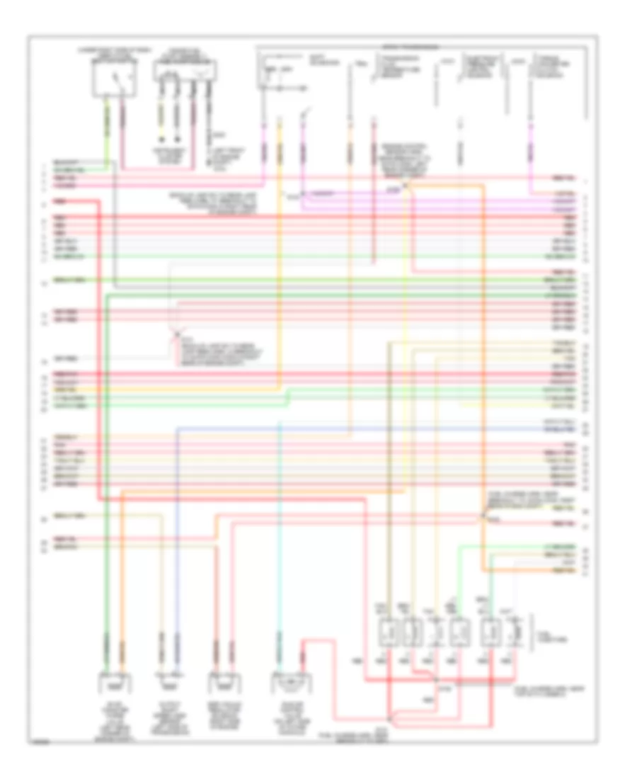
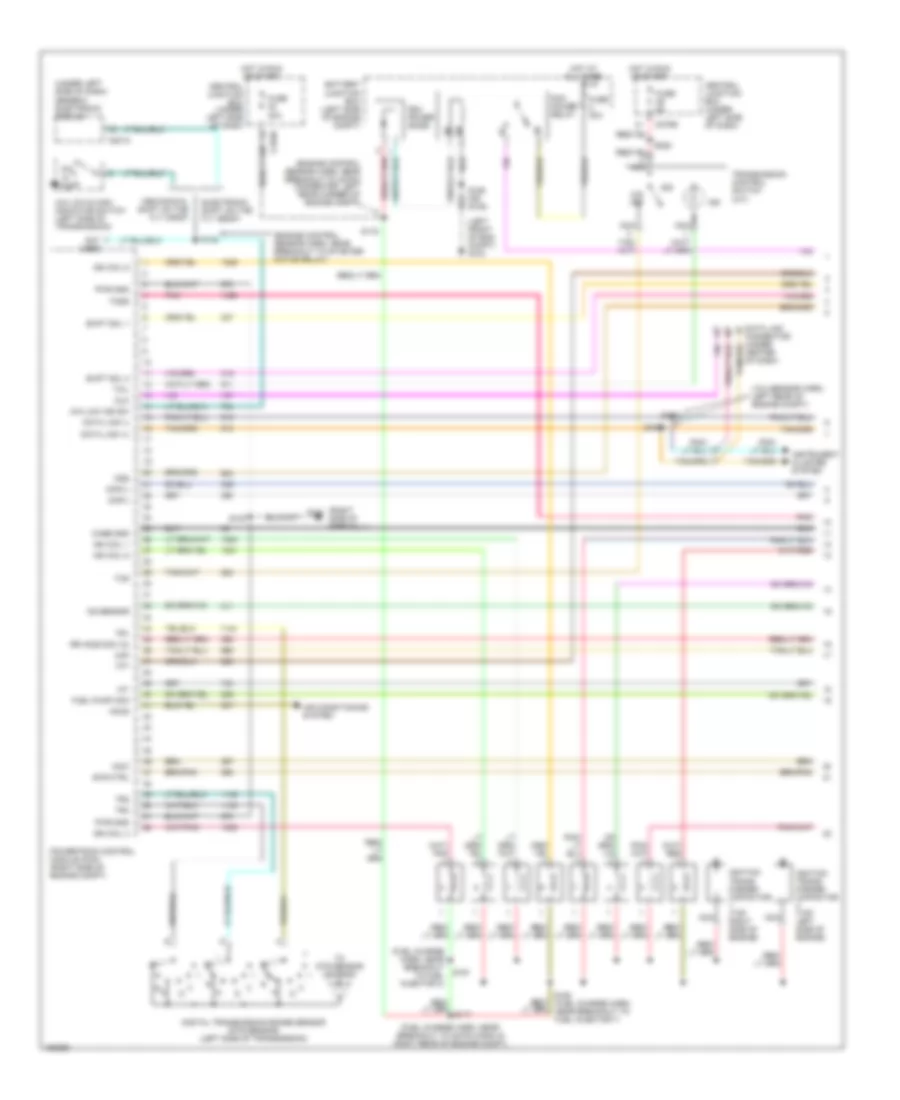
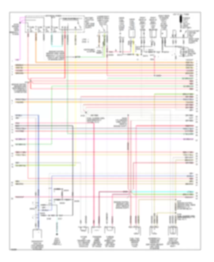
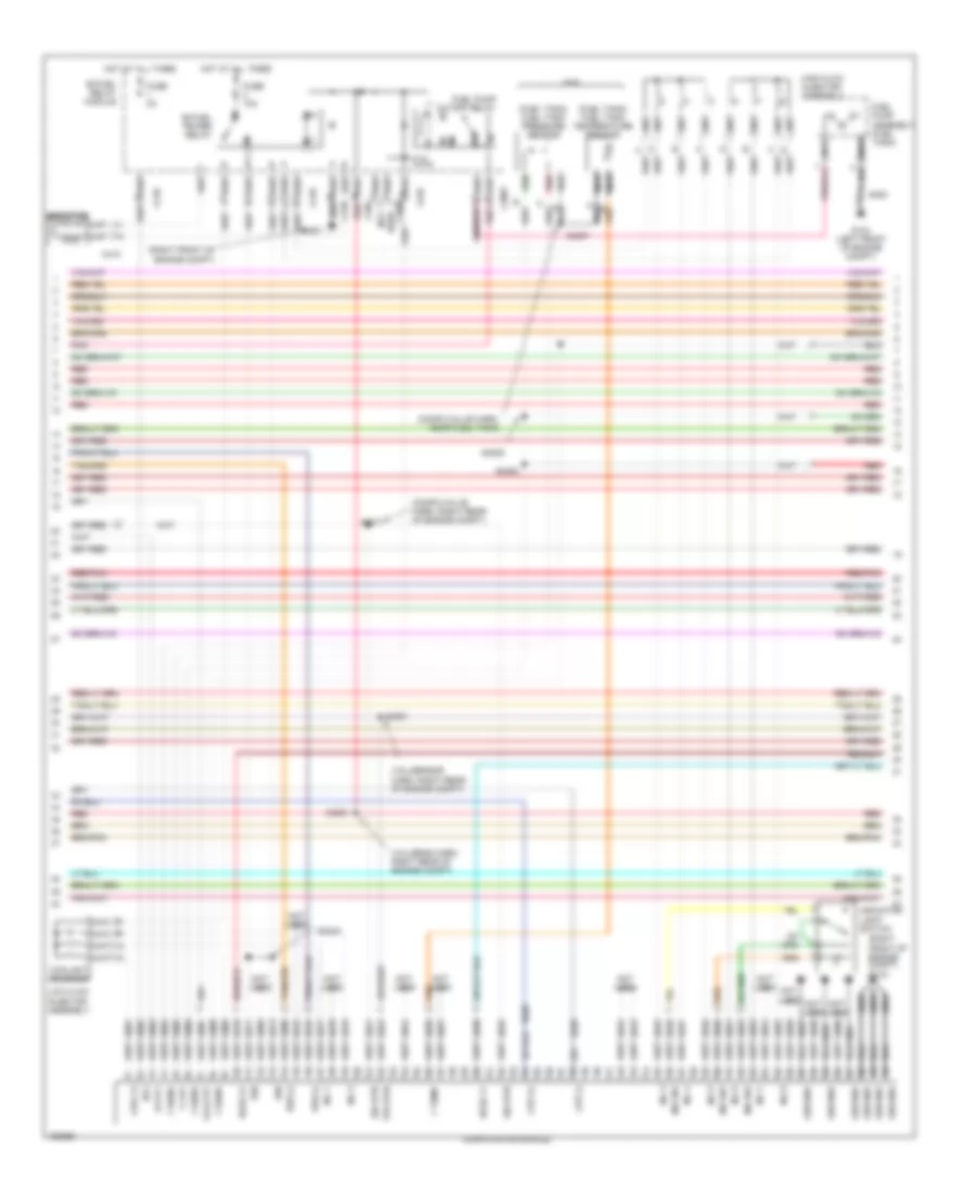
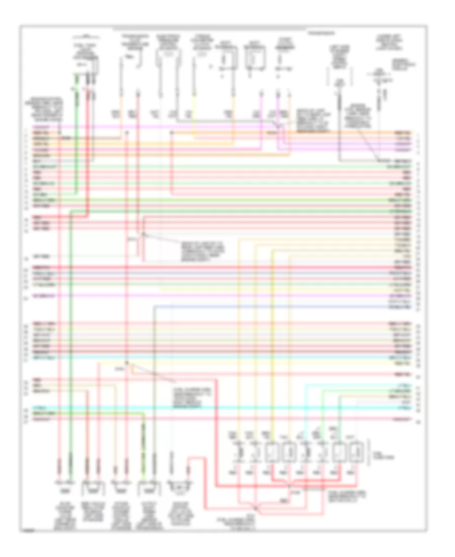
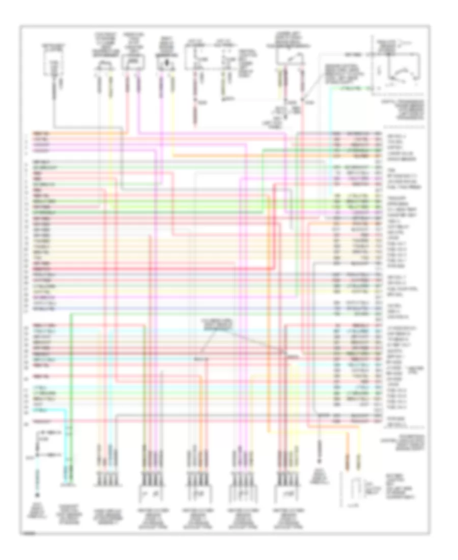
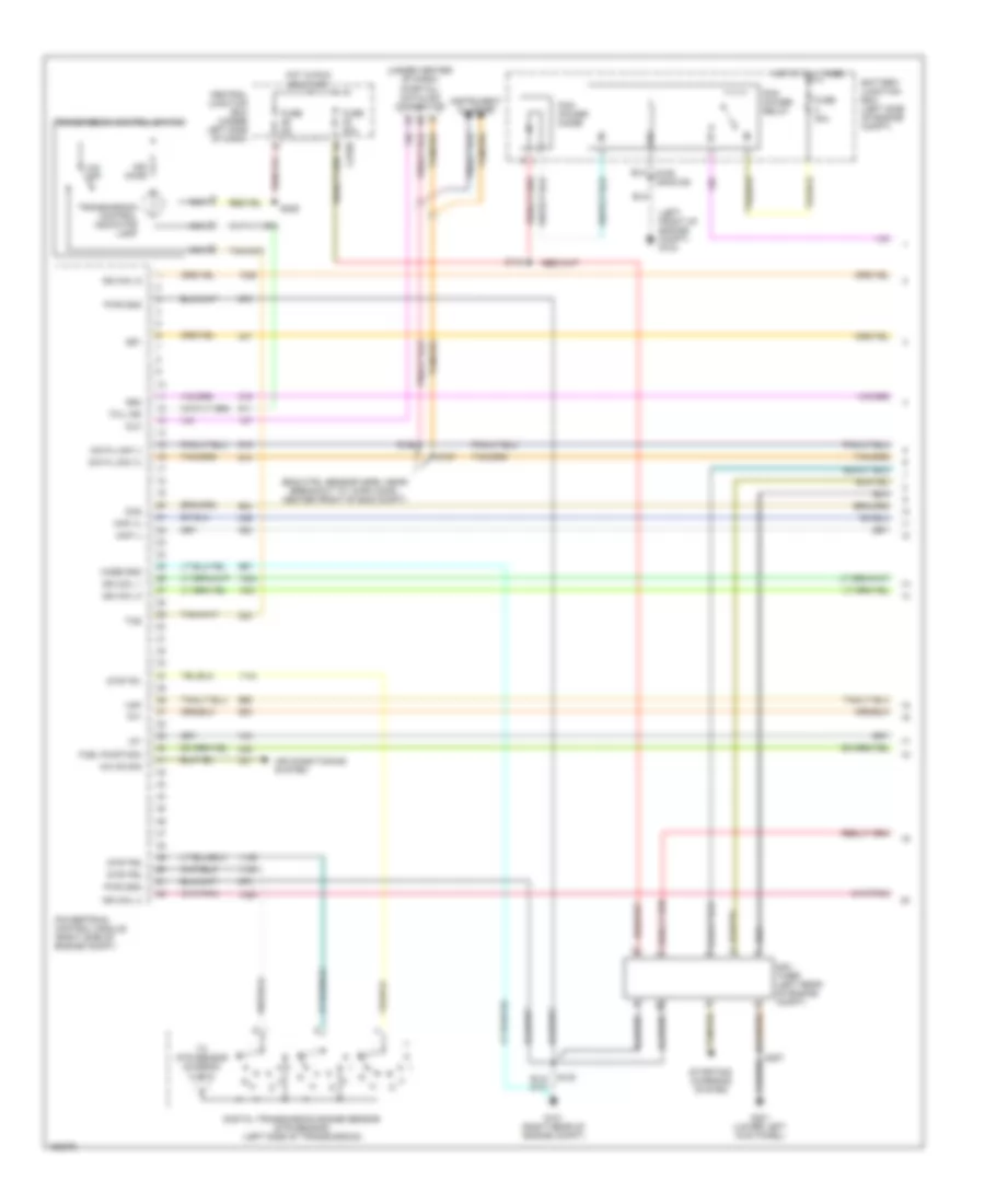
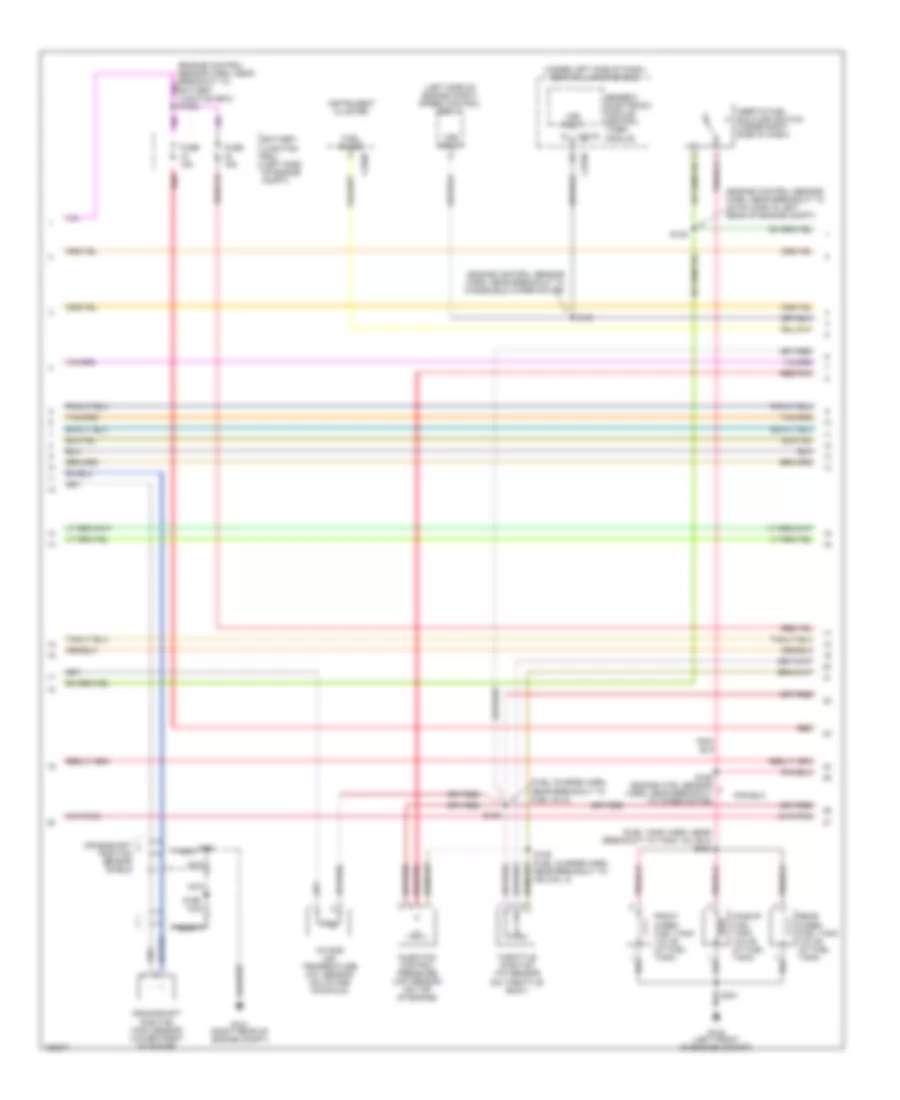
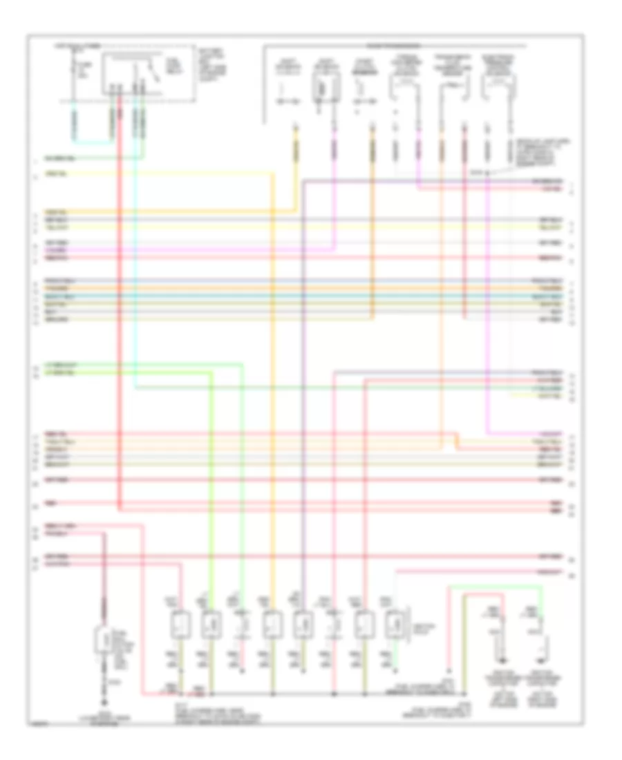
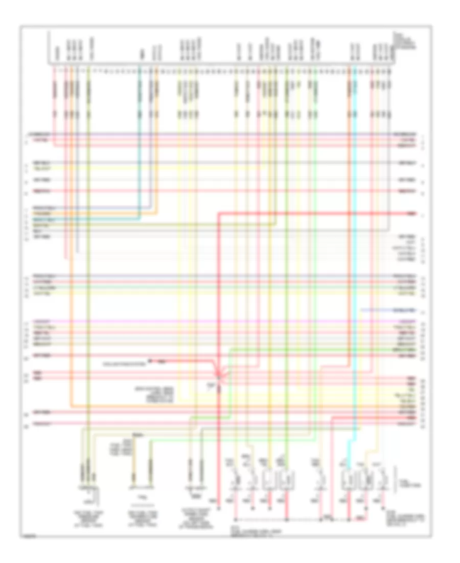
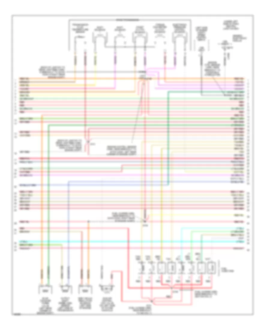
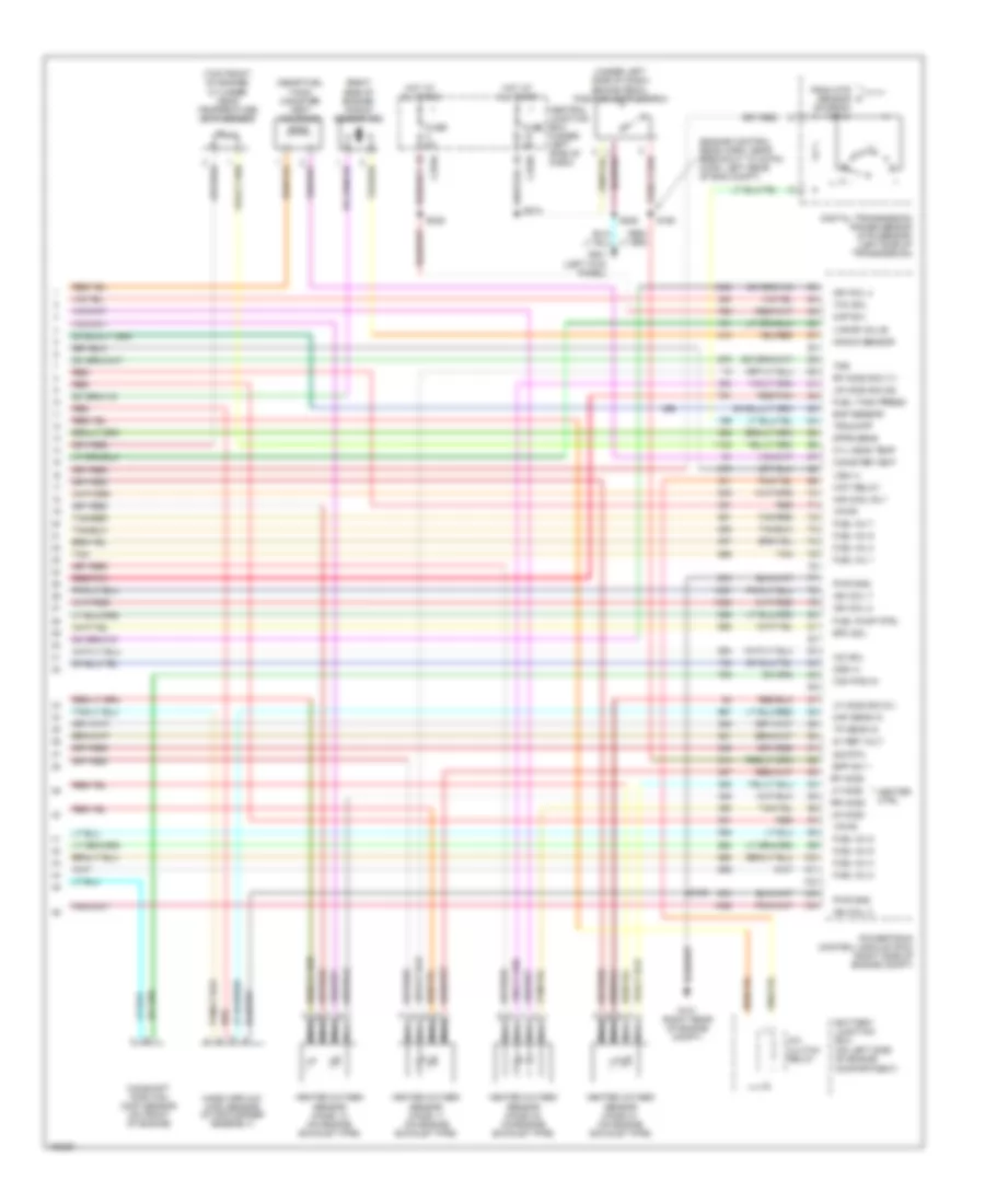
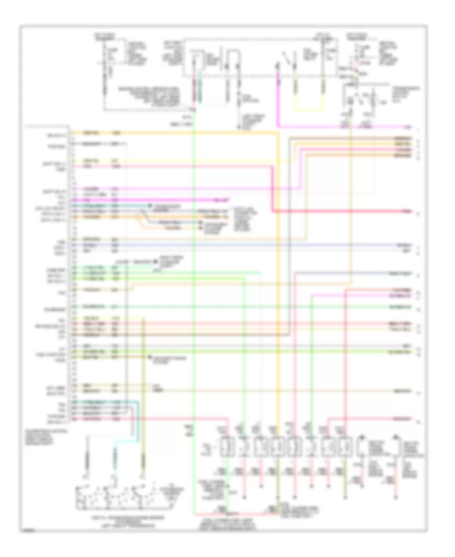
5.4L, Engine Performance Wiring Diagrams, with 4R100 Transmission (1 of 4) for Ford Pickup F150 2002
 https://portal-diagnostov.com/license.html
Automotive Electricians Portal FZCO
Automotive Electricians Portal FZCO
https://portal-diagnostov.com/license.html
https://portal-diagnostov.com/license.html
Automotive Electricians Portal FZCO
Automotive Electricians Portal FZCOList of elements for 5.4L, Engine Performance Wiring Diagrams, with 4R100 Transmission (1 of 4) for Ford Pickup F150 2002:
- (engine control sensor harn, near breakout to 40-pin connector, left rear left rear corner of eng compt)
- (fuel charge harn, near breakout to 42-pin conn in right rear of engine compt)
- (fuel charge harn, near breakout to fuel injector 3)
- (left front of engine compt) g104
- (right rear of engine compt)
- 4x4 low ind sw
- Accs
- Air conditioning system
- Battery junction box (left side of engine compt)
- C270b
- Capacitor (top left side of engine)
- Case gnd
- Central junction box (under left side of dash)
- Ckp(+)
- Ckp(-)
- Coil on plug
- Css
- Data link (+)
- Data link (-)
- Data link connector (partial) (under center of dash)
- Digital transmission range sensor (dtr sensor) (left side of transmission)
- Dlc
- Evr ctrl
- Fuel pump mon
- Fuse 30a
- Fuse 5a
- G101
- Hot at all times
- Hot in run or start
- Iat
- Ign coil 1
- Ign coil 3
- Ign coil 5
- Ign coil 6
- Ignition trans- former
- Ignition trans- former capacitor (top right side of engine)
- Ind
- Instrument cluster system
- Ks sensor
- Maf
- Nca
- Not used
- O/d off
- Pcm power diode
- Pcm power relay
- Pnk
- Powertrain control module (pcm) (right side of engine compt)
- Pwr gnd
- R n
- Rr ho2s sig (12)
- S100
- S106 (or s105)
- S116
- S161
- S162 (fuel charge harn, near breakout to fuel injector 7)
- S225
- Shift sol a
- Shift sol b
- Tcil
- Tcs
- Tcss
- Tft
- To dtr sensor (diagram 4 of 4)
- Tr1
- Tr2
- Tr4
- Transmission control switch (a/t)
- Transmission system
5.4L, Engine Performance Wiring Diagrams, with 4R100 Transmission (2 of 4) for Ford Pickup F150 2002
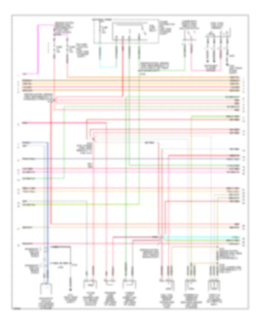 https://portal-diagnostov.com/license.html
Automotive Electricians Portal FZCO
Automotive Electricians Portal FZCO
https://portal-diagnostov.com/license.html
https://portal-diagnostov.com/license.html
Automotive Electricians Portal FZCO
Automotive Electricians Portal FZCOList of elements for 5.4L, Engine Performance Wiring Diagrams, with 4R100 Transmission (2 of 4) for Ford Pickup F150 2002:
- (engine control sensor harn, near breakout to 40-pin conn in left rear of engine compt)
- (engine control sensor harn, near breakout to windshield wiper motor) s127
- (engine control sensor harn, right rear of engine compt)
- (fuel tank) fuel pump assembly
- (under right side of dash) inertia fuel shut-off switch
- Battery junction box (left side of engine compt)
- Crankshaft position (ckp) sensor (lower front of engine)
- Crankshaft position sensor shield
- Differential pressure feedback egr (dpfe) sensor (left side of engine)
- Fuel pump relay
- Fuel tank pressure sensor transducer (in fuel tank)
- Fuse 15a
- Fuse 20a
- G101 (right rear of engine compt)
- G104 (left front of eng compt)
- Hot at all times
- Instrument cluster system
- Intake air temperature (iat) sensor (on intake manifold)
- Nca
- Pnk
- Power distribution box (left side of engine compt)
- Red
- Red/pnk
- S100
- S135 (fuel charge harn, near breakout to fuel inj 8)
- S136 (fuel charge harn, near breakout to fuel inj 7)
- S137 (engine control sensor harn, near breakout to starter relay)
- S138
- S139
- S199
- S400
- Throttle position (tp) sensor (on throttle body)
- Transfer case speed sensor (left rear of trans)
- Turbine shaft speed (tss) sensor (left rear of trans)
5.4L, Engine Performance Wiring Diagrams, with 4R100 Transmission (3 of 4) for Ford Pickup F150 2002
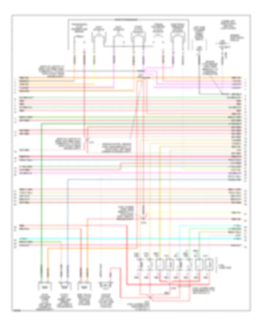 https://portal-diagnostov.com/license.html
Automotive Electricians Portal FZCO
Automotive Electricians Portal FZCO
https://portal-diagnostov.com/license.html
https://portal-diagnostov.com/license.html
Automotive Electricians Portal FZCO
Automotive Electricians Portal FZCOList of elements for 5.4L, Engine Performance Wiring Diagrams, with 4R100 Transmission (3 of 4) for Ford Pickup F150 2002:
- (back-up lamp sw to rear lamp feed harn, in breakout to 38-pin conn in right rear engine compt)
- (engine control sensor harn, near breakout to 40-pin conn, left rear corner of engine compt)
- (engine ctrl sensor harn, near breakout to windsheild wiper motor)
- (fuel charge harn, near breakout to 16-pin conn, right rear of engine compt)
- (fuel charge harn, near breakout to ignition coil 3)
- (left side of engine compt) speed control servo
- (under left side of dash) central junction box
- 4r100 transmission
- C201d
- Coast clutch solenoid
- Egr vacuum regulator solenoid (left side of engine)
- Electronic pressure control solenoid
- Evap canister purge
- Fuel injectors
- Generic electronic module
- Idle air control (iac) valve (on left side of intake manifold)
- Output shaft speed (oss) sensor (left side of transmission)
- Red
- Red/pnk
- S129
- S131 (fuel charge harn, near breakout to ign coil 7)
- S140
- S141
- S143
- S154
- S155
- Shift solenoid a
- Shift solenoid b
- Tan
- Tan/ red
- Tan/red
- Torque converter clutch solenoid
- Transmission fluid temperature sensor
- Valve (left rear corner of engine compt)
- Vss input
5.4L, Engine Performance Wiring Diagrams, with 4R100 Transmission (4 of 4) for Ford Pickup F150 2002
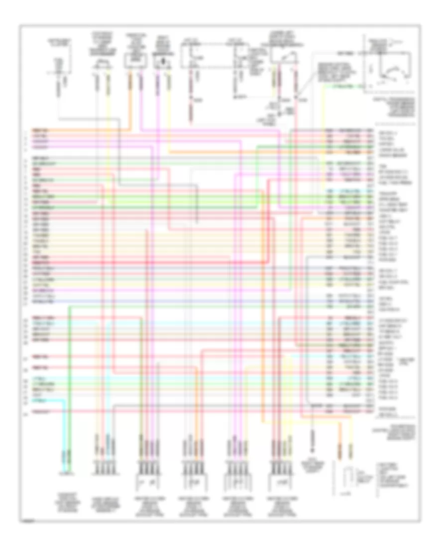 https://portal-diagnostov.com/license.html
Automotive Electricians Portal FZCO
Automotive Electricians Portal FZCO
https://portal-diagnostov.com/license.html
https://portal-diagnostov.com/license.html
Automotive Electricians Portal FZCO
Automotive Electricians Portal FZCOList of elements for 5.4L, Engine Performance Wiring Diagrams, with 4R100 Transmission (4 of 4) for Ford Pickup F150 2002:
- (engine control sens harn, near breakout to 40-pin conn, left rear of eng compt)
- (near fuel tank) evap canister vent valve
- (on left side of engine compartment)
- (right side of engine) knock sensor (ks)
- (top front of engine) cylinder head temperature (cht) sensor
- (under left side of dash) brake pedal position (bpp) switch
- 5v ref volt
- A/c clutch relay
- Battery junction box
- Bpp sw
- Cam pos in
- Camshaft position (cmp) sensor (on front of engine)
- Canister vent
- Central junction box (under left side of dash)
- Cyl head temp
- Digital transmission range sensor (dtr sensor) (left side of transmission)
- Dpfe sens
- Epc sol
- From dtr sensor (diagram 1 of 4)
- Fuel cap off ind
- Fuel inj 1
- Fuel inj 2
- Fuel inj 3
- Fuel inj 4
- Fuel inj 5
- Fuel inj 6
- Fuel inj 7
- Fuel inj 8
- Fuel pump ctrl
- Fuel tank press
- Fuse 5a
- G101 (right rear of engine compt)
- G201 (left kick panel)
- Heated oxygen sensor (ho2s) 11 (on engine exhaust pipe)
- Heated oxygen sensor (ho2s) 12 (on engine exhaust pipe)
- Heated oxygen sensor (ho2s) 21 (on engine exhaust pipe)
- Heated oxygen sensor (ho2s) 22 (on engine exhaust pipe)
- Heater ctrl
- Hot at all times
- Iac sol
- Ign coil 2
- Ign coil 4
- Ign coil 7
- Ign coil 8
- Ind ctrl
- Instrument cluster
- Kap b(+)
- Knock sensor
- Lf ho2s
- Lf ho2s sig (21)
- Lr ho2s
- Lr ho2s sig (22)
- Maf sens in
- Mass airflow (maf) sensor (in air cleaner assembly)
- Nca
- Oss (+)
- Powertrain control module (pcm) (right side of engine compt)
- Pwr gnd
- Red
- Red/pnk
- Rf ho2s
- Rf ho2s sig (11)
- Rr ho2s
- S100
- S160
- S208
- S236
- S274
- Sig rtn
- Tan
- Tan/red
- Tcc sol
- Tp sens in
- Tr3a/cpp
- Tss
- Vapor valve
- Vpwr
- Vss (+)
- Wot relay
5.4L, Engine Performance Wiring Diagrams, with 4R70W Transmission (1 of 4) for Ford Pickup F150 2002
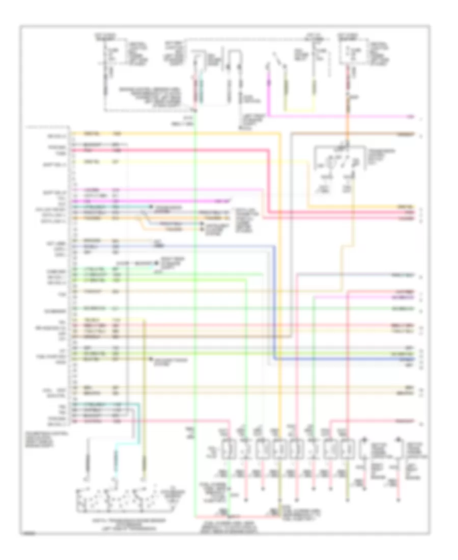 https://portal-diagnostov.com/license.html
Automotive Electricians Portal FZCO
Automotive Electricians Portal FZCO
https://portal-diagnostov.com/license.html
https://portal-diagnostov.com/license.html
Automotive Electricians Portal FZCO
Automotive Electricians Portal FZCOList of elements for 5.4L, Engine Performance Wiring Diagrams, with 4R70W Transmission (1 of 4) for Ford Pickup F150 2002:
- (4.6l)
- (engine control sensor harn, near breakout to 40-pin connector, left rear left rear corner of eng compt)
- (fuel charge harn, near breakout to 42-pin conn in right rear of engine compt)
- (fuel charge harn, near breakout to fuel injector 3)
- (left front of engine compt) g104
- (right rear of engine compt)
- 4x4 low ind sw
- Accs
- Air conditioning system
- Battery junction box (left side of engine compt)
- Capacitor (left front of engine)
- Case gnd
- Central junction box (under left side of dash)
- Ckp(+)
- Ckp(-)
- Coil on plug
- Data link (+)
- Data link (-)
- Data link connector (partial) (under center of dash)
- Digital transmission range sensor (dtr sensor) (left side of transmission)
- Dlc
- Evr ctrl
- Fuel pump mon
- Fuse 30a
- Fuse 5a
- G101
- Hot at all times
- Hot in run or start
- Iat
- Ign coil 1
- Ign coil 3
- Ign coil 5
- Ign coil 6
- Ignition trans- former
- Ignition trans- former capacitor (right front of engine)
- Imcc
- Ind
- Instrument cluster system
- Ks sensor
- Maf
- Nca
- Not used
- O/d off
- Pcm power diode
- Pcm power relay
- Pnk
- Powertrain control module (pcm) (right side of engine compt)
- Pwr gnd
- R n
- Rr ho2s sig (12)
- S100
- S106 (or s105)
- S116
- S161
- S162 (fuel charge harn, near breakout to fuel injector 7)
- Shift sol a
- Shift sol b
- Tcil
- Tcs
- Tcss
- Tft
- To dtr sensor (diagram 4 of 4)
- Tr1
- Tr2
- Tr4
- Transmission control switch (a/t)
- Transmission system
5.4L, Engine Performance Wiring Diagrams, with 4R70W Transmission (2 of 4) for Ford Pickup F150 2002
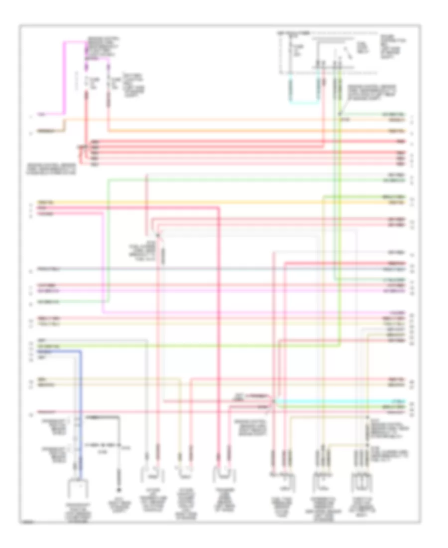 https://portal-diagnostov.com/license.html
Automotive Electricians Portal FZCO
Automotive Electricians Portal FZCO
https://portal-diagnostov.com/license.html
https://portal-diagnostov.com/license.html
Automotive Electricians Portal FZCO
Automotive Electricians Portal FZCOList of elements for 5.4L, Engine Performance Wiring Diagrams, with 4R70W Transmission (2 of 4) for Ford Pickup F150 2002:
- (engine control sensor harn, near breakout to 40-pin conn in left rear of engine compt)
- (engine control sensor harn, near breakout to windshield wiper motor)
- (engine control sensor harn, right rear of engine compt)
- (not used)
- Battery junction box (left side of engine compt)
- Crankshaft position (ckp) sensor (lower front of engine)
- Crankshaft position sensor shield
- Differential pressure feedback egr (dpfe) sensor (left side of engine)
- Fuel pump relay
- Fuel tank pressure sensor (in fuel tank)
- Fuse 15a
- Fuse 20a
- G101 (right rear of engine compt)
- Hot at all times
- Intake air temperature (iat) sensor (on intake manifold)
- Intake manifold runner control module (4.6l) (right side of engine)
- Nca
- Pnk
- Power distribution box (left side of engine compt)
- Red
- Red/pnk
- S100
- S127
- S135 (fuel charge harn, near breakout to fuel inj 8)
- S136 (fuel charge harn, near breakout to fuel inj 7)
- S137 (engine control sensor harn, near breakout to starter relay)
- S138
- S139
- S199
- Throttle position (tp) sensor (on throttle body)
- Transfer case speed sensor (left rear of trans)
5.4L, Engine Performance Wiring Diagrams, with 4R70W Transmission (3 of 4) for Ford Pickup F150 2002
 https://portal-diagnostov.com/license.html
Automotive Electricians Portal FZCO
Automotive Electricians Portal FZCO
https://portal-diagnostov.com/license.html
https://portal-diagnostov.com/license.html
Automotive Electricians Portal FZCO
Automotive Electricians Portal FZCOList of elements for 5.4L, Engine Performance Wiring Diagrams, with 4R70W Transmission (3 of 4) for Ford Pickup F150 2002:
- (back-up lamp sw to rear lamp feed harn, in breakout to 38-pin conn in right rear engine compt)
- (engine control sensor harn, near breakout to 40-pin conn, left rear corner
- (engine ctrl sensor harn, near breakout to windsheild wiper motor)
- (fuel charge harn, near breakout to 16-pin conn, right rear of engine compt)
- (fuel charge harn, near breakout to ignition coil 3)
- (fuel tank) fuel pump module
- (left side of engine compt) speed control servo
- (under left side of dash) central junction box
- 4r70w transmission
- C201d
- Egr vacuum regulator solenoid (left side of engine)
- Electronic pressure control solenoid
- Evap canister purge
- Fuel injectors
- G104 (left front of engine compt)
- Generic electronic module
- Idle air control (iac) valve (on left side of intake manifold)
- Inertia fuel shut-off switch (under right side of dash)
- Instrument cluster system
- Nca
- Of engine compt)
- Output shaft speed (oss) sensor (left side of transmission)
- Pressure controllers
- Red
- Red/pnk
- S129
- S131 (fuel charge harn, near breakout to ign coil 7)
- S140
- S141
- S143
- S154
- S155
- S400
- Tan
- Tan/ red
- Tan/red
- Torque converter clutch solenoid
- Transmission fluid temperature sensor
- Valve (left rear corner of engine compt)
- Vss input
5.4L, Engine Performance Wiring Diagrams, with 4R70W Transmission (4 of 4) for Ford Pickup F150 2002
 https://portal-diagnostov.com/license.html
Automotive Electricians Portal FZCO
Automotive Electricians Portal FZCO
https://portal-diagnostov.com/license.html
https://portal-diagnostov.com/license.html
Automotive Electricians Portal FZCO
Automotive Electricians Portal FZCOList of elements for 5.4L, Engine Performance Wiring Diagrams, with 4R70W Transmission (4 of 4) for Ford Pickup F150 2002:
- (engine control sens harn, near breakout to 40-pin conn, left rear of eng compt)
- (near fuel tank) canister vent solenoid
- (on left side of engine compartment)
- (right side of engine) knock sensor (ks)
- (top front of engine) cylinder head temperature (cht) sensor
- (under left side of dash) brake pedal position (bpp)switch
- 5v ref volt
- A/c clutch relay
- A/t
- Battery junction box
- Bpp sw
- Cam pos in
- Camshaft position (cmp) sensor (on front of engine)
- Canister vent
- Central junction box (under left side of dash)
- Check fuel cap ind
- Cooling fan system
- Cyl head temp
- Digital transmission range sensor (dtr sensor) (left side of transmission)
- Dpfe sens
- Epc sol
- From dtr sensor (diagram 1 of 4)
- Fuel inj 1
- Fuel inj 2
- Fuel inj 3
- Fuel inj 4
- Fuel inj 5
- Fuel inj 6
- Fuel inj 7
- Fuel inj 8
- Fuel pump ctrl
- Fuel tank press
- Fuse 5a
- G101 (right rear of engine compt)
- G201 (left kick panel)
- Heated oxygen sensor (ho2s) 11 (on engine exhaust pipe)
- Heated oxygen sensor (ho2s) 12 (on engine exhaust pipe)
- Heated oxygen sensor (ho2s) 21 (on engine exhaust pipe)
- Heated oxygen sensor (ho2s) 22 (on engine exhaust pipe)
- Heater ctrl
- Hot at all times
- Hot in start
- Iac sol
- Ign coil 2
- Ign coil 4
- Ign coil 7
- Ign coil 8
- Ind ctrl
- Instrument cluster
- Kap b(+)
- Knock sensor
- Lf ho2s
- Lf ho2s sig (21)
- Lr ho2s
- Lr ho2s sig (22)
- M/t
- Maf sens in
- Mass airflow (maf) sensor (in air cleaner assembly)
- Nca
- Not used
- Oss (+)
- Powertrain control module (pcm) (right side of engine compt)
- Pwr gnd
- Red
- Red/pnk
- Rf ho2s
- Rf ho2s sig (11)
- Rr ho2s
- S100
- S160
- S208
- S236
- S274
- Sig rtn
- Tan
- Tan/red
- Tcc sol
- Tp sens in
- Tr3a/cpp
- Vapor valve
- Vpwr
- Vss (+)
- Wot relay
EXTERIOR LIGHTS
Back-up Lamps Wiring Diagram for Ford Pickup F150 2002
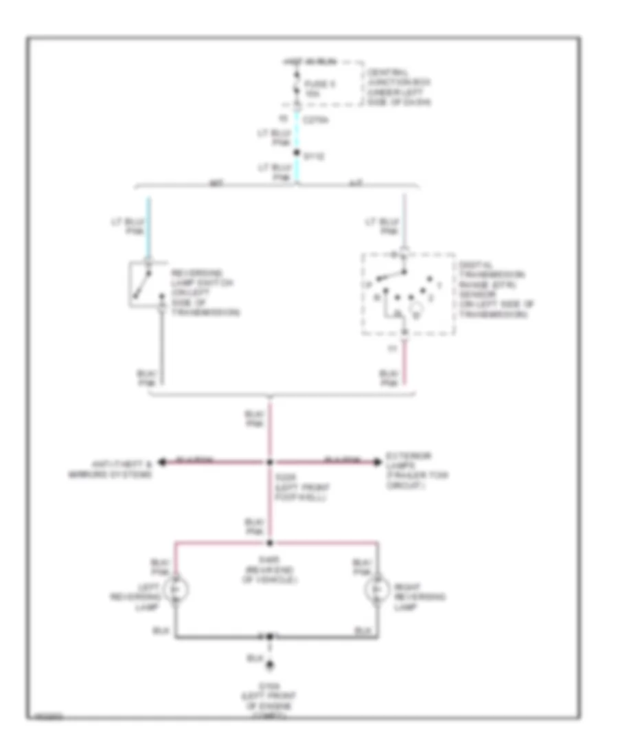 https://portal-diagnostov.com/license.html
Automotive Electricians Portal FZCO
Automotive Electricians Portal FZCO
https://portal-diagnostov.com/license.html
https://portal-diagnostov.com/license.html
Automotive Electricians Portal FZCO
Automotive Electricians Portal FZCOList of elements for Back-up Lamps Wiring Diagram for Ford Pickup F150 2002:
- A/t
- Anti-theft & mirrors systems
- C270a
- Central junction box (under left side of dash)
- Digital transmission range (dtr) sensor (on left side of transmission)
- Exterior lamps (trailer tow circuit)
- Fuse 5 15a
- G104 (left front of engine compt)
- Hot in run
- Lamp
- Left
- M/t
- Reversing
- Reversing lamp switch (on left side of transmission)
- Right reversing lamp
- S112
- S226 (left front footwell)
- S401
- S405 (rear end of vehicle)
Exterior Lamps Wiring Diagram (1 of 2) for Ford Pickup F150 2002
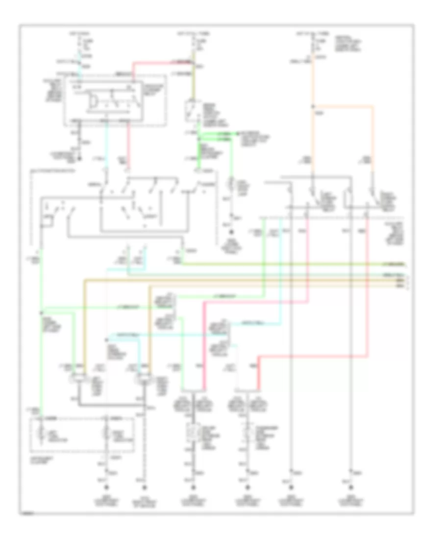 https://portal-diagnostov.com/license.html
Automotive Electricians Portal FZCO
Automotive Electricians Portal FZCO
https://portal-diagnostov.com/license.html
https://portal-diagnostov.com/license.html
Automotive Electricians Portal FZCO
Automotive Electricians Portal FZCOList of elements for Exterior Lamps Wiring Diagram (1 of 2) for Ford Pickup F150 2002:
- (lower right kick panel) g200
- (w/ central security module)
- (w/o central security module)
- 87a
- Auxiliary relay box 4 (behind center of dash)
- Auxiliary relay box 5 (behind left side of dash)
- Brake pedal position switch (under left side of dash)
- C202a
- C220a
- C220b
- C270a
- C270b
- Central junction box (under left side of dash)
- Driver side exterior rear view mirror
- Exterior lights system (trailer tow circuit)
- Fuse 10a
- Fuse 20a
- Fuse 5a
- G103 (right front of vehicle)
- G200 (lower right kick panel)
- Hazard
- High mount stop lamp
- Hot at all times
- Hot in run
- Indicator flasher relay
- Instrument cluster
- Left
- Left front park/ turn lamp
- Left mirror turn signal relay
- Left turn indicator
- Multi-function switch
- Nca
- Normal
- Passenger side exterior rear view mirror
- Pnk
- Red
- Right
- Right front park/ turn lamp
- Right mirror turn signal relay
- Right turn indicator
- S104
- S202
- S204
- S220
- S221
- S228
- S246 (under left side of dash)
- S247 (near steering column)
- S500
- S600
- S911
Exterior Lamps Wiring Diagram (2 of 2) for Ford Pickup F150 2002
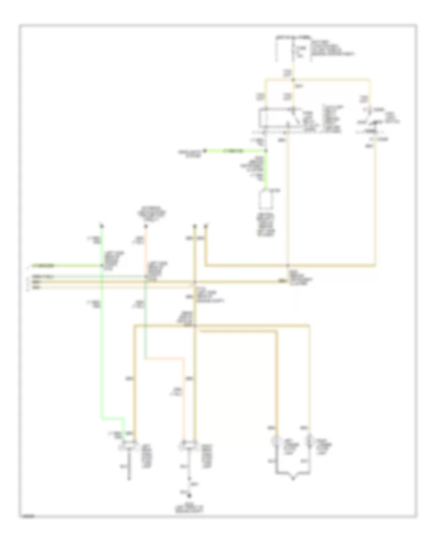 https://portal-diagnostov.com/license.html
Automotive Electricians Portal FZCO
Automotive Electricians Portal FZCO
https://portal-diagnostov.com/license.html
https://portal-diagnostov.com/license.html
Automotive Electricians Portal FZCO
Automotive Electricians Portal FZCOList of elements for Exterior Lamps Wiring Diagram (2 of 2) for Ford Pickup F150 2002:
- (left side rear of engine compt) s148
- (left side rear of engine compt) s149
- (rear end of vehicle) s403
- Auxiliary relay box 3 (behind right center of dash)
- Battery junction box (in left side of engine compartment)
- C205b
- C274b
- Central security module (behind left side of dash)
- Cluster)
- Engine compt)
- Exterior lights system (trailer tow circuit)
- Fuse 15a
- G104 (left front of engine compt)
- Head
- Headlights system
- Hot at all times
- Left license plate lamp
- Left rear park/ stop/ turn lamp
- Main light switch
- Off
- Park
- Park lamp relay (w/ auto lamps)
- Right license plate lamp
- Right rear park/ stop/ turn lamp
- S241
- S245 (behind instrument cluster
- S401
Trailer/Camper Adapter Wiring Diagram for Ford Pickup F150 2002
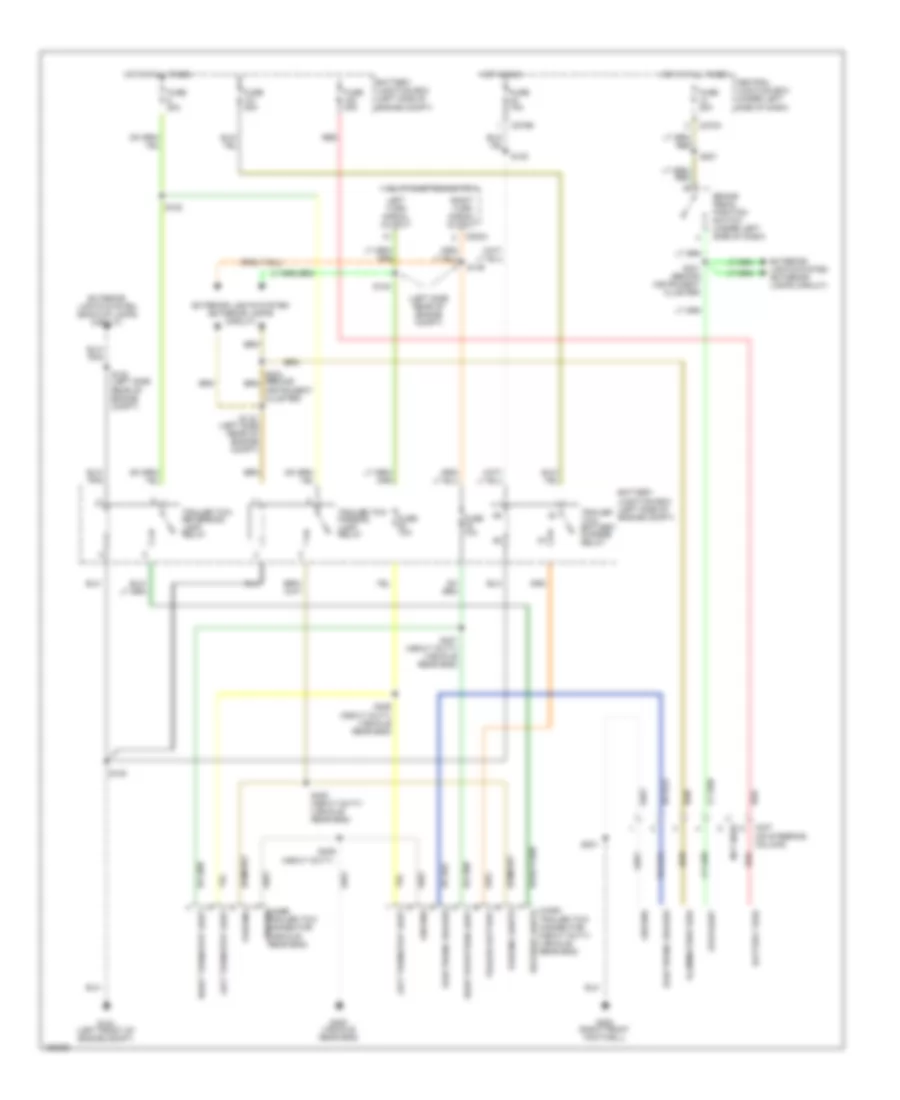 https://portal-diagnostov.com/license.html
Automotive Electricians Portal FZCO
Automotive Electricians Portal FZCO
https://portal-diagnostov.com/license.html
https://portal-diagnostov.com/license.html
Automotive Electricians Portal FZCO
Automotive Electricians Portal FZCOList of elements for Trailer/Camper Adapter Wiring Diagram for Ford Pickup F150 2002:
- (behind instrument cluster)
- (heavy duty)
- (left side rear of engine compt)
- Battery feed
- Battery junction box (left side of engine compt)
- Brake pedal position switch (under left side of dash)
- C202a
- C237 (on steering column)
- C270a
- C270b
- C439a trailer tow connector (heavy duty) (vehicle rear end)
- C439b trailer tow connector (vehicle rear end)
- Central junction box (under left side of dash)
- Electronic brakes
- Exterior lights system (back-up lamps circuit)
- Exterior lights system (exterior lamps circuit)
- Fuse 10a
- Fuse 20a
- Fuse 30a
- G104 (left front of engine compt)
- G200 (right front footwell)
- G400 (vehicle rear end)
- Ground
- Hot at all times
- Hot in run
- Illumination feed
- Instrument cluster)
- Left turn signal output
- Left turn/stop light
- Multi-function switch
- Not used
- Parking
- Parking lights
- Red
- Reverse lights
- Right stop/turn light
- Right turn signal output
- Right turn/stop light
- S105
- S108
- S115
- S120
- S130 (left side rear of engine compt)
- S148
- S149
- S201
- S221
- S231
- S406 (heavy duty) (vehicle rear end)
- S407 (heavy duty) (vehicle rear end)
- S408 (heavy duty) (vehicle rear end)
- S409
- Stoplight
- Trailer battery
- Trailer tow battery charge relay
- Trailer tow parking lamp relay
- Trailer tow reversing lamp relay
GROUND DISTRIBUTION
Ground Distribution Wiring Diagram (1 of 4) for Ford Pickup F150 2002
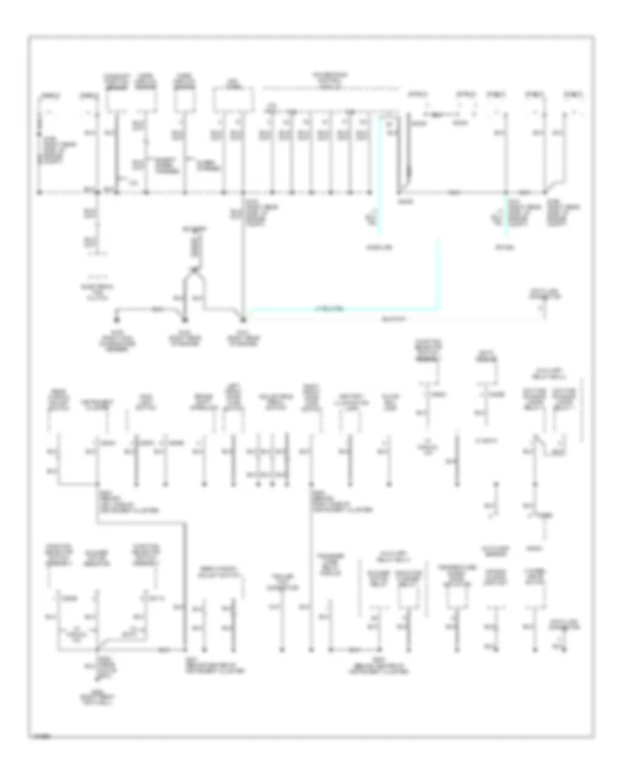 https://portal-diagnostov.com/license.html
Automotive Electricians Portal FZCO
Automotive Electricians Portal FZCO
https://portal-diagnostov.com/license.html
https://portal-diagnostov.com/license.html
Automotive Electricians Portal FZCO
Automotive Electricians Portal FZCOList of elements for Ground Distribution Wiring Diagram (1 of 4) for Ford Pickup F150 2002:
- 4 wheel drive switch
- 4.2l
- 4.6l 5.4l
- Adjustable pedal switch
- Air bag sliding contact
- Ashtray illumination lamp
- Autolamp sensor
- Auxiliary relay box 2
- Auxiliary relay box 4
- Battery
- Bi-fuel
- Blower motor relay
- Blower motor resistor
- Brake shift interlock
- C205a
- C205b
- C220a
- C228b
- C271a
- C290b
- C294b
- C294c
- Camshaft position sensor
- Data link connector
- Daytime running lamps relay 1
- Daytime running lamps relay 2
- Eatc module
- Electronic fan clutch
- Except super- charged
- Function selector switch assembly
- G100 (right rear of engine)
- G101 (right rear of engine)
- G105 (right main chassis side member)
- G200 (right front footwell)
- Gasoline
- Glove box lamp
- Glove box)
- Indicator flasher relay
- Instrument cluster
- Left front door ajar switch
- Main light switch
- Mass airflow sensor
- Ngv timer
- Powertrain control module
- Radio
- Rear window adjust switch
- Right front door ajar switch
- S101 (right rear side of engine compt)
- S199 (right rear side of engine compt)
- S201 (behind center of instrument cluster)
- S202 (behind center of instrument cluster)
- S203 (behind right side of instrument cluster)
- S204 (behind left side of instrument cluster)
- S4034
- S4035
- S4036
- Shield
- Super- charged
- Temperature blend door actuator
- Trailer tow connector
- Transfer case relay module
- W/ eatc
- W/ manual a/c
Ground Distribution Wiring Diagram (2 of 4) for Ford Pickup F150 2002
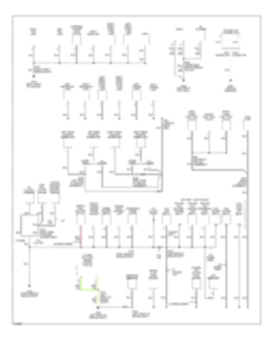 https://portal-diagnostov.com/license.html
Automotive Electricians Portal FZCO
Automotive Electricians Portal FZCO
https://portal-diagnostov.com/license.html
https://portal-diagnostov.com/license.html
Automotive Electricians Portal FZCO
Automotive Electricians Portal FZCOList of elements for Ground Distribution Wiring Diagram (2 of 4) for Ford Pickup F150 2002:
- 4 pin connector
- 4 wheel anti-lock brake system module
- 4.2l
- 4.2l, 5.4l ngv
- 5.4l ngv
- 7 pin connector
- 87a
- A/c clutch diode
- A/c clutch solenoid
- All others
- Battery junction box
- Brake fluid level switch
- Cd changer
- Charge air cooler pump motor
- Digital trans- mission range sensor
- Dropping resistor
- Engine comp- artment lamp
- Engine compt)
- Except ngv
- Fog lamp relay
- Front in-bed fuel tank valve
- Fuel pump
- Fuel pump high/ low relay
- Fuel rail cutoff valve
- G102 (right rear of engine compt)
- G103 (right front of vehicle)
- G104 (left front of engine compt)
- G202 (left front footwell)
- G400 (vehicle rear end)
- Horn
- Inertia fuel shutoff switch
- Intake manifold runner control module
- Left fog lamp
- Left front park/ turn lamp
- Left front running board lamp
- Left headlamp
- Left license lamp
- Left rear park/ stop/ turn lamp
- Left rear running board lamp
- Left reversing lamp
- Midship fuel tank valve
- Of engine compartment)
- Others
- Pcm power relay
- Radio
- Rear in-bed fuel tank valve
- Right fog lamp
- Right front park/ turn lamp
- Right front running board lamp
- Right headlamp
- Right license lamp
- Right rear park/ stop/ turn lamp
- Right rear running board lamp
- Right reversing lamp
- S102 (right rear of engine compt)
- S105 (left rear of engine compt)
- S106 (left front of engine compt)
- S172 (left front of engine compt)
- S329 (right side of vehicle underbody)
- S339 (left side of vehicle underbody)
- S400 (rear vehicle underbody)
- S401 (vehicle rear end)
- Speed control servo
- Super crew
- Supercharged
- Trailer tow battery charge relay
- Trailer tow connector
- Trailer tow parking lamp relay
- Trailer tow reversing lamp relay
- W/ super crew
- W/ trailer tow
- W/o super crew
- Windshield wiper motor
- Winshield washer pump motor
Ground Distribution Wiring Diagram (3 of 4) for Ford Pickup F150 2002
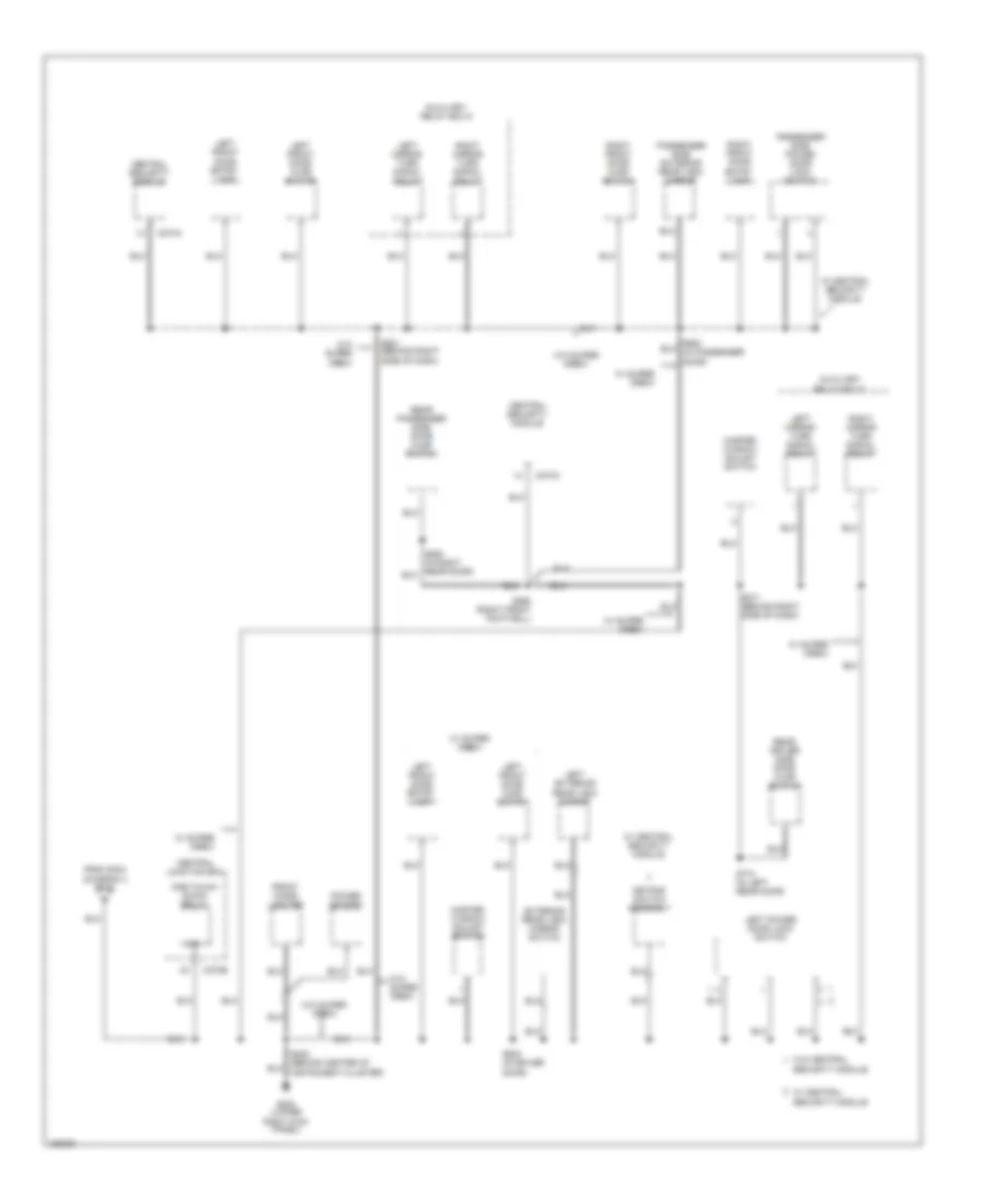 https://portal-diagnostov.com/license.html
Automotive Electricians Portal FZCO
Automotive Electricians Portal FZCO
https://portal-diagnostov.com/license.html
https://portal-diagnostov.com/license.html
Automotive Electricians Portal FZCO
Automotive Electricians Portal FZCOList of elements for Ground Distribution Wiring Diagram (3 of 4) for Ford Pickup F150 2002:
- 87a
- Auxiliary relay box 5
- C270b
- C274a
- Central junction box
- Central security module
- Exterior rear view mirror switch
- From s304 (diagram 4 of 4)
- Front cigar lighter
- G200 (lower right kick panel)
- Keypad switch assembly
- Left exterior rear view mirror
- Left front door ajar switch
- Left front door entry lamp
- Left mirror turn signal relay
- Left power door lock switch
- Master window adjust switch
- One touch down relay
- Passenger side exterior rear view mirror
- Passenger side power door lock switch
- Power socket
- Rear driver side door ajar switch
- Rear passenger side door ajar switch
- Right front door ajar switch
- Right front door entry lamp
- Right mirror turn signal relay
- S260 (right front footwell)
- S271 (behind right side of dash)
- S500 (in driver door)
- S501 (behind right side of dash)
- S774 (in left rear door)
- Security module
- W/ central security module
- W/ super crew
- W/o central
- W/o super crew
Ground Distribution Wiring Diagram (4 of 4) for Ford Pickup F150 2002
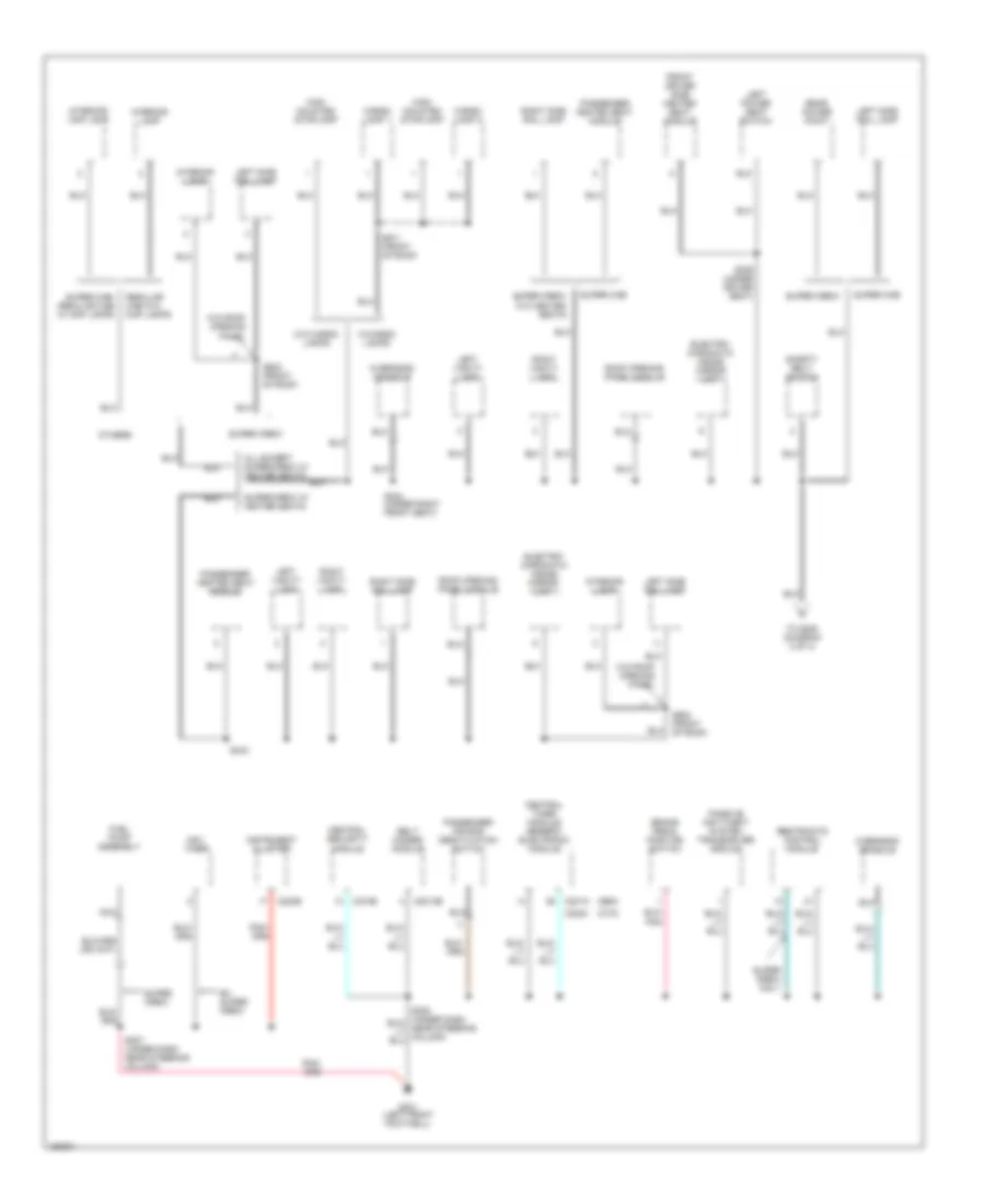 https://portal-diagnostov.com/license.html
Automotive Electricians Portal FZCO
Automotive Electricians Portal FZCO
https://portal-diagnostov.com/license.html
https://portal-diagnostov.com/license.html
Automotive Electricians Portal FZCO
Automotive Electricians Portal FZCOList of elements for Ground Distribution Wiring Diagram (4 of 4) for Ford Pickup F150 2002:
- (ctm)
- (gem)
- All except super crew w/ heated seats
- Belt minder module
- Brake pedal position switch
- C2013b
- C201a
- C220b
- C2224
- C274b
- Cargo lamp 1
- Cargo lamp 2
- Central security module
- Central timer module/ generic electronic module
- Electro- chromatic inside mirror unit
- Ex super crew
- Front driver side heated seat module
- Fuel pump assembly
- G201 (left front footwell)
- High mounted stoplamp
- Instrument cluster
- Interior lamp
- Interior/ map lamp
- Left power seat switch
- Left side rail lamp
- Left vanity lamp
- Nca
- Ngv timer
- Others
- Overhead console
- Passenger air bag deactivation switch
- Passenger heated seat module
- Passive anti-theft system transceiver module
- Rear power point
- Regular cab w/o map lamps
- Restraints control module
- Right side rail lamp
- Right vanity lamp
- Roof opening panel module
- S207 (under dash near steering column)
- S304 (under right front seat)
- S306 (under driver seat)
- S343
- S902 (front of roof)
- S911 (front of roof)
- Safety belt switch
- Super cab
- Super cab/ regular cab w/ map lamps
- Super crew
- Super crew only
- Super crew w/ heated seats
- Super crew w/o heated seats
- To s205 (diagram 3 of 4)
- W/cargo lamps
- W/o cargo lamps
- W/o roof opening panel
HEADLIGHTS
Autolamps & Fog Lamps Wiring Diagram, with DRL for Ford Pickup F150 2002
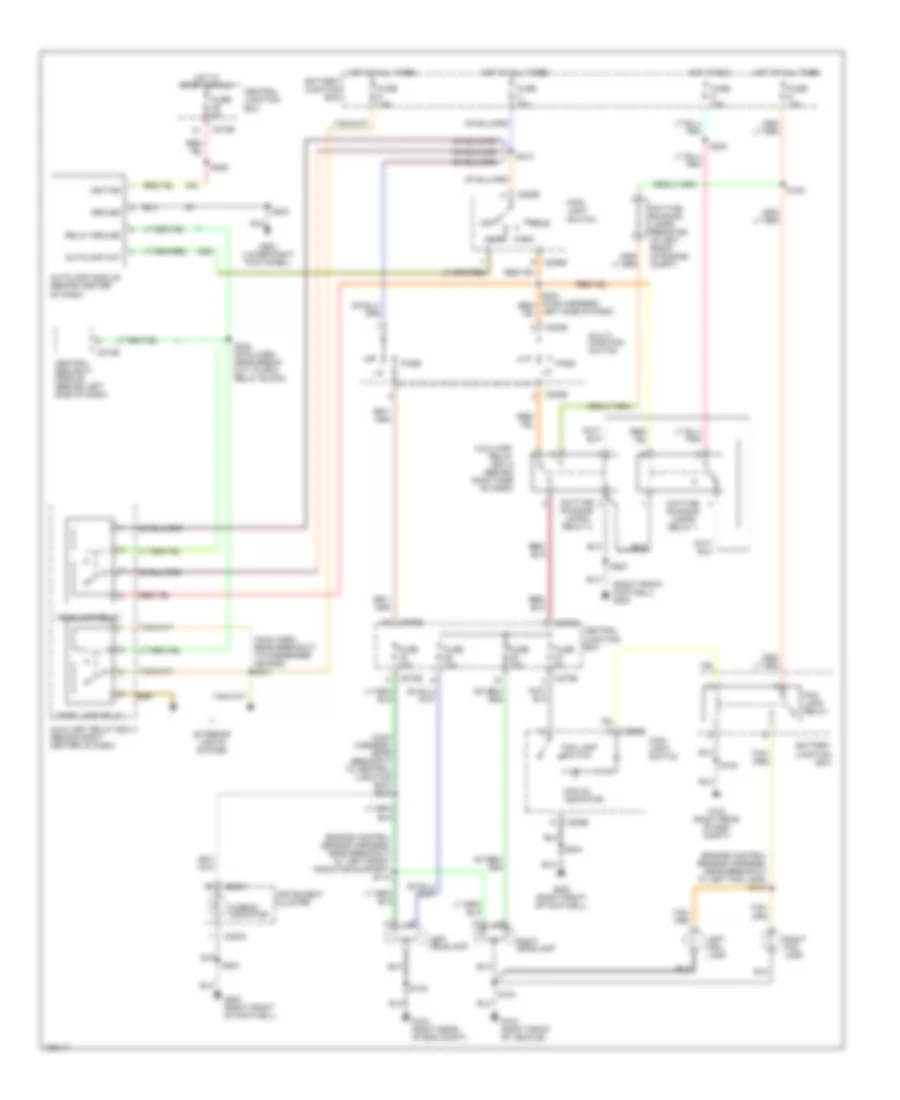 https://portal-diagnostov.com/license.html
Automotive Electricians Portal FZCO
Automotive Electricians Portal FZCO
https://portal-diagnostov.com/license.html
https://portal-diagnostov.com/license.html
Automotive Electricians Portal FZCO
Automotive Electricians Portal FZCOList of elements for Autolamps & Fog Lamps Wiring Diagram, with DRL for Ford Pickup F150 2002:
- (engine control sensor harness, near breakout at left front radiator support) s114
- (engine control sensor harness, near breakout to left fog lamp) s147
- (main harn, near breakout to passenger air bag) s241
- (main harness, near breakout to central junction box) s218
- (right front footwell) g200
- Auto
- Autolamp module (behind center of dash)
- Autolamp out
- Auxiliary relay box 2 (behind right side of dash)
- Auxiliary relay box 3 (behind right center of dash)
- Battery junction box
- C202b
- C205b
- C220a
- C270b
- C274b
- Central junction box
- Central security module (behind left side of dash)
- Daytime running lamps relay 1
- Daytime running lamps relay 2
- Daytime running lamps resistor (in left front of engine compt)
- Exterior lights system
- Fog lamp relay
- Fog lamp switch
- Fog on indicator
- Fuse 10a
- Fuse 15a
- Fuse 20a
- Fuse 30a
- Fuse 5a
- G102 (right rear of eng compt)
- G103 (right front of vehicle)
- G200 (lower right kick panel)
- G200 (right front of footwell)
- Ground
- Head
- Headlamp relay
- Hi-beam indicator
- Hot at all times
- Hot in run
- Hot in start or run
- Ignition
- Instrument cluster
- Left fog lamp
- Left headlamp
- Left side of dash)
- Main light switch
- Multi- function switch
- Off
- Park
- Park lamp relay
- Pass
- Relay ground
- Right fog lamp
- Right headlamp
- S104
- S105
- S109
- S203
- S204
- S212
- S222
- S225
- S245 (main harn, near break- out to rpo relay block)
Autolamps & Fog Lamps Wiring Diagram, without DRL for Ford Pickup F150 2002
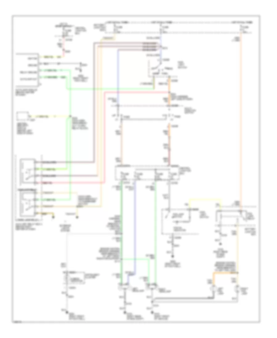 https://portal-diagnostov.com/license.html
Automotive Electricians Portal FZCO
Automotive Electricians Portal FZCO
https://portal-diagnostov.com/license.html
https://portal-diagnostov.com/license.html
Automotive Electricians Portal FZCO
Automotive Electricians Portal FZCOList of elements for Autolamps & Fog Lamps Wiring Diagram, without DRL for Ford Pickup F150 2002:
- (engine control sensor harness, near breakout at left front radiator support) s114
- (engine control sensor harness, near breakout to left fog lamp) s147
- (main harn, near breakout to passenger switch) s241
- (main harness, near breakout to central junction box) s218
- Auto
- Autolamp module (behind center of dash)
- Autolamp out
- Auxiliary relay box 3 (behind right center of dash)
- Battery junction box
- C202b
- C205b
- C220a
- C257
- C270a
- C270b
- Central junction box
- Central security module (behind left side of dash)
- Exterior lights system
- Fog lamp relay
- Fog lamp switch
- Fog on indicator
- Fuse 10a
- Fuse 15a
- Fuse 20a
- Fuse 30a
- Fuse 5a
- G102 (right rear of eng compt)
- G103 (right front of vehicle)
- G200 (right front footwell)
- G200 (right front of footwell)
- Ground
- Head
- Headlamp relay
- Hi-beam indicator
- Hot at all times
- Hot in start or run
- Ignition
- Instrument cluster
- Left fog lamp
- Left headlamp
- Main light switch
- Multi- function switch
- Off
- Park
- Park lamp relay
- Pass
- Relay ground
- Right fog lamp
- Right headlamp
- S104
- S105
- S203
- S204
- S212
- S225
- S244 (main harness, left side of dash)
- S245 (main harn, near break- out to rpo relay block)
Headlamps & Fog Lamps Wiring Diagram, with DRL for Ford Pickup F150 2002
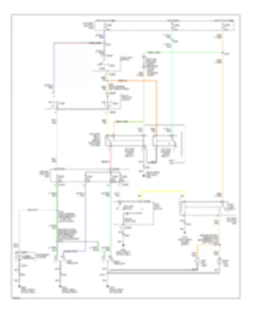 https://portal-diagnostov.com/license.html
Automotive Electricians Portal FZCO
Automotive Electricians Portal FZCO
https://portal-diagnostov.com/license.html
https://portal-diagnostov.com/license.html
Automotive Electricians Portal FZCO
Automotive Electricians Portal FZCOList of elements for Headlamps & Fog Lamps Wiring Diagram, with DRL for Ford Pickup F150 2002:
- (engine control sensor harn, near breakout to left fog lamp) s147
- (right front footwell) g200
- Auxiliary relay box 2 (behind right side of dash)
- Battery junction box
- C202b
- C205b
- C220a
- C270a
- C270b
- Central junction box
- Daytime running lamps relay 1
- Daytime running lamps relay 2
- Daytime running lamps resistor (in left front of engine compt)
- Fog lamp relay
- Fog lamp switch
- Fog on indicator
- Fuse 10a
- Fuse 15a
- Fuse 20a
- Fuse 30a
- Fuse 5a
- G102 (right rear of eng compt)
- G103 (right front of vehicle)
- G200 (right front of footwell)
- Head
- Hi-beam indicator
- Hot at all times
- Hot in run
- Instrument cluster
- Left fog lamp
- Left headlamp
- Left side of dash)
- Main light
- Main light switch
- Multi- function switch
- Off
- Park
- Pass
- Right fog lamp
- Right headlamp
- S104
- S105
- S109
- S203
- S204
- S212
- S218 (main harness, near breakout to central junction box)
- S222
- Switch
Headlamps & Fog Lamps Wiring Diagram, without DRL for Ford Pickup F150 2002
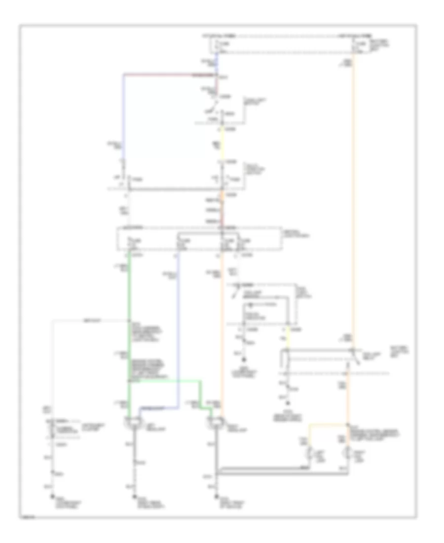 https://portal-diagnostov.com/license.html
Automotive Electricians Portal FZCO
Automotive Electricians Portal FZCO
https://portal-diagnostov.com/license.html
https://portal-diagnostov.com/license.html
Automotive Electricians Portal FZCO
Automotive Electricians Portal FZCOList of elements for Headlamps & Fog Lamps Wiring Diagram, without DRL for Ford Pickup F150 2002:
- (engine control sensor harness, near breakout at left front radiator support) s114
- Battery junction box
- C202b
- C205b
- C220a
- C270a
- C270b
- Central junction box
- Fog lamp relay
- Fog lamp switch
- Fog on indicator
- Fuse 10a
- Fuse 15a
- Fuse 20a
- Fuse 30a
- Fuse 5a
- G102 (rear of right fender apron)
- G102 (right rear of eng compt)
- G103 (right front of vehicle)
- G200 (lower right kick panel)
- Head
- Hi-beam indicator
- Hot at all times
- Instrument cluster
- Left fog lamp
- Left headlamp
- Main light
- Main light switch
- Multi- function switch
- Off
- Park
- Pass
- Right fog lamp
- Right headlamp
- S104
- S105
- S147 (engine control sensor harness, near breakout to left fog lamp)
- S204
- S212
- S218 (main harness, near breakout to central junction box)
- Switch
HORN
Horn Wiring Diagram for Ford Pickup F150 2002
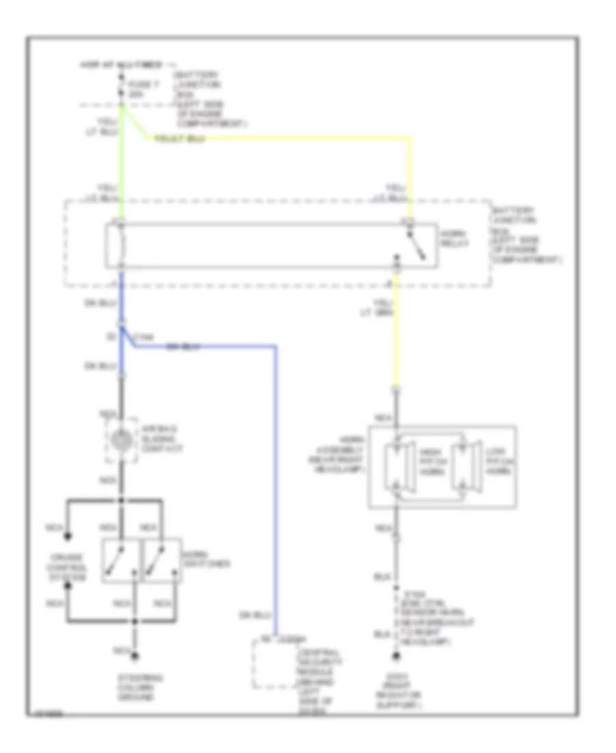 https://portal-diagnostov.com/license.html
Automotive Electricians Portal FZCO
Automotive Electricians Portal FZCO
https://portal-diagnostov.com/license.html
https://portal-diagnostov.com/license.html
Automotive Electricians Portal FZCO
Automotive Electricians Portal FZCOList of elements for Horn Wiring Diagram for Ford Pickup F150 2002:
- (right
- Air bag sliding contact
- Battery junction
- Battery junction box (left side of engine compartment)
- Box (left side of engine compartment)
- C144
- C274a
- Central security module (behind left side of dash)
- Cruise control system
- Fuse 7 20a
- G103
- Headlamp)
- High pitch horn
- Horn assembly (near right headlamp)
- Horn relay
- Horn switches
- Hot at all times
- Low pitch horn
- Nca
- Radiator support)
- S104
- Steering column ground
INSTRUMENT CLUSTER
Instrument Cluster Wiring Diagram for Ford Pickup F150 2002
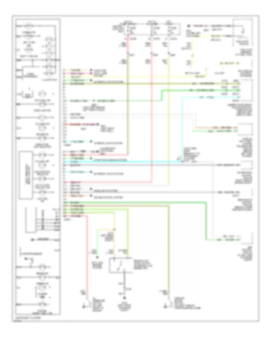 https://portal-diagnostov.com/license.html
Automotive Electricians Portal FZCO
Automotive Electricians Portal FZCO
https://portal-diagnostov.com/license.html
https://portal-diagnostov.com/license.html
Automotive Electricians Portal FZCO
Automotive Electricians Portal FZCOList of elements for Instrument Cluster Wiring Diagram for Ford Pickup F150 2002:
- (ctm)
- (gem)
- (lower right kick panel) g200
- 4x4 high ind
- 4x4 low ind
- 5.4l ngv
- 820 ohms
- A10
- A11
- A12
- A13
- A14
- A16
- A17
- A18
- A19
- A20
- Abs control module (in left side of engine compt)
- Airbag ind
- Anti-lock brakes system
- Anti-lock ind
- B10
- B14
- B15
- B17
- B22
- Bias ckt
- Brake fluid level switch (on brake fluid reservoir)
- Brake ind
- C2015
- C201a
- C201b
- C220a
- C220b
- C2224
- C270a
- C270b
- Central junction box
- Charge ind
- Check fuel cap indicator
- Cluster) s232
- Computer data lines system
- Cruise control system
- Cruise ind
- Door ajar ind
- Exc 5.4l ngv
- Exterior lights system
- Fasten safety belt ind
- Fuel pump assembly (at fuel tank)
- Fuel pump module
- Fuse 30a
- Fuse 5a
- G104 (left front of engine compt)
- G201 (left front footwell)
- G201 (lower left kick panel)
- Generic electronic module/ central timer module (behind left side of dash)
- Headlights system
- Hi beam ind
- Hot at all times
- Hot in run
- Hot in start or run
- Illumination
- Instrument cluster
- Interior lights system
- Left turn ind
- Low fuel ind
- Low oil/high coolant ind
- Malfunction indicator
- Micro- processor
- Microprocessor
- Nca
- Ngv module (on front of engine)
- Oil pressure switch (on left front of engine)
- Parking brake switch (on right side of parking brake lever)
- Passive anti-theft system transceiver module (behind left side of dash)
- Powertrain control module (right side of engine compt)
- Restraints control module (behind lower center of dash)
- Right turn ind
- S106
- S170 (left rear engine compt)
- S204
- S207
- S236
- S237
- S265
- S268 (main harn, behind left side of dash)
- Starting/charging system
- Theft indicator micro cluster
Overhead Console Wiring Diagram for Ford Pickup F150 2002
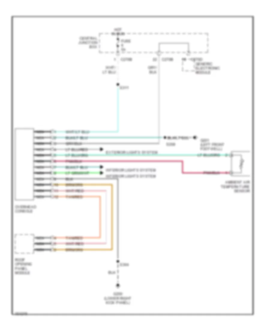 https://portal-diagnostov.com/license.html
Automotive Electricians Portal FZCO
Automotive Electricians Portal FZCO
https://portal-diagnostov.com/license.html
https://portal-diagnostov.com/license.html
Automotive Electricians Portal FZCO
Automotive Electricians Portal FZCOList of elements for Overhead Console Wiring Diagram for Ford Pickup F150 2002:
- Ambient air temperature sensor
- C270b
- C270d
- Central junction box
- Exterior lights system
- Fuse 5a
- G200 (lower right kick panel)
- G201 (left front footwell)
- Generic electronic module
- Hot in run
- Interior lights system
- Nca
- Overhead console
- Roof opening panel module
- S208
- S304
- S311
- Tan/red
INTERIOR LIGHTS
Courtesy Lamps Wiring Diagram, Except Supercrew for Ford Pickup F150 2002
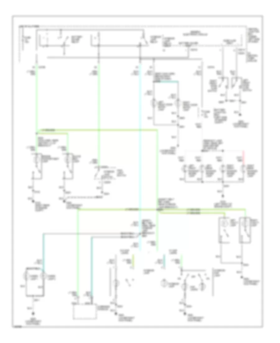 https://portal-diagnostov.com/license.html
Automotive Electricians Portal FZCO
Automotive Electricians Portal FZCO
https://portal-diagnostov.com/license.html
https://portal-diagnostov.com/license.html
Automotive Electricians Portal FZCO
Automotive Electricians Portal FZCOList of elements for Courtesy Lamps Wiring Diagram, Except Supercrew for Ford Pickup F150 2002:
- s240 (main harn, near ashtray illum breakout)
- (body main harn, behind right side of dash) s239
- (rear ext lamp harn, near left side center of vehicle) s341
- (right rear of engine compt)
- (safety belt ret harn, near interior lamp breakout) s900
- (safety belt ret harn, near interior lamp breakout) s904
- (w/ central timer module)
- Battery junction box (left side of engine compt)
- Battery saver input
- Battery saver relay
- C201a
- C201d
- C205a
- C2224
- C270a
- C270b
- Cargo lamp 1
- Cargo lamp 2
- Central junction box (under left side of dash)
- Door ajar input
- Engine compartment lamp
- Fuse 10a
- Fuse 15a
- G102
- G104 (left front of engine compt)
- G200 (lower right kick panel)
- Generic electronic module
- Glove box lamp
- Hot at all times
- Interior lamp
- Interior lamp relay
- Interior lamp relay input
- Interior lamp switch
- Interior/ map lamp
- Left front door ajar switch
- Left front door entry lamp
- Left front running board lamp
- Left rear running board lamp
- Left vanity lamp
- Main light switch
- Map lamps
- Nca
- Off
- Overhead console
- Right front door entry lamp
- Right front door ajar switch
- Right front running board lamp
- Right rear running board lamp
- Right vanity lamp
- S102
- S203
- S204
- S304
- S400
- S501
- S600
- S911
- W/ map lamps
- W/0 map lamps
Courtesy Lamps Wiring Diagram, Supercrew for Ford Pickup F150 2002
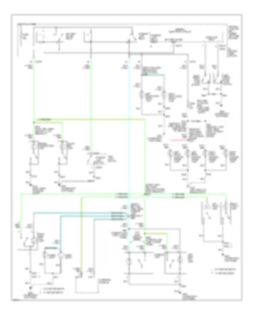 https://portal-diagnostov.com/license.html
Automotive Electricians Portal FZCO
Automotive Electricians Portal FZCO
https://portal-diagnostov.com/license.html
https://portal-diagnostov.com/license.html
Automotive Electricians Portal FZCO
Automotive Electricians Portal FZCOList of elements for Courtesy Lamps Wiring Diagram, Supercrew for Ford Pickup F150 2002:
- s240 (main harn, near ashtray illum breakout)
- (body main harn, behind right side of dash) s239
- (right rear of engine compt)
- (safety belt ret harn, near aux power point breakout) s305
- (safety belt ret harn, near interior lamp breakout) s900
- (w/ central timer module)
- Battery junction box (left side of engine compt)
- Battery saver input
- Battery saver relay
- C201a
- C201d
- C205a
- C2224
- C270a
- C270b
- Cargo lamp 1
- Cargo lamp 2
- Central junction box (under left side of dash)
- Door ajar input
- Engine compartment lamp
- Fuse 10a
- Fuse 15a
- G102
- G104 (left front of engine compt)
- G200 (lower right kick panel)
- Generic electronic module
- Glove box lamp
- Hot at all times
- Interior lamp
- Interior lamp relay
- Interior lamp relay input
- Interior lamp switch
- Left front door ajar switch
- Left front door entry lamp
- Left front running board lamp
- Left rear running board lamp
- Left side rail lamp
- Left vanity lamp
- Main light switch
- Nca
- Overhead console
- Right front door entry lamp
- Right front door ajar switch
- Right front running board lamp
- Right rear running board lamp
- Right side rail lamp
- Right vanity lamp
- S102
- S203
- S204
- S304
- S329
- S331 (rear ext lamp harn, near front of right running board)
- S339
- S341 (rear ext lamp harn, near left side center of vehicle)
- S343
- S501
- S600
- S901 (interior lamp harn, in roof panel)
- S902
- S903 (interior lamp harn, in roof panel)
- S911
- W/ heated seats
- W/o heated seats
- W/o roof opening panel
Instrument Illumination Wiring Diagram (1 of 2) for Ford Pickup F150 2002
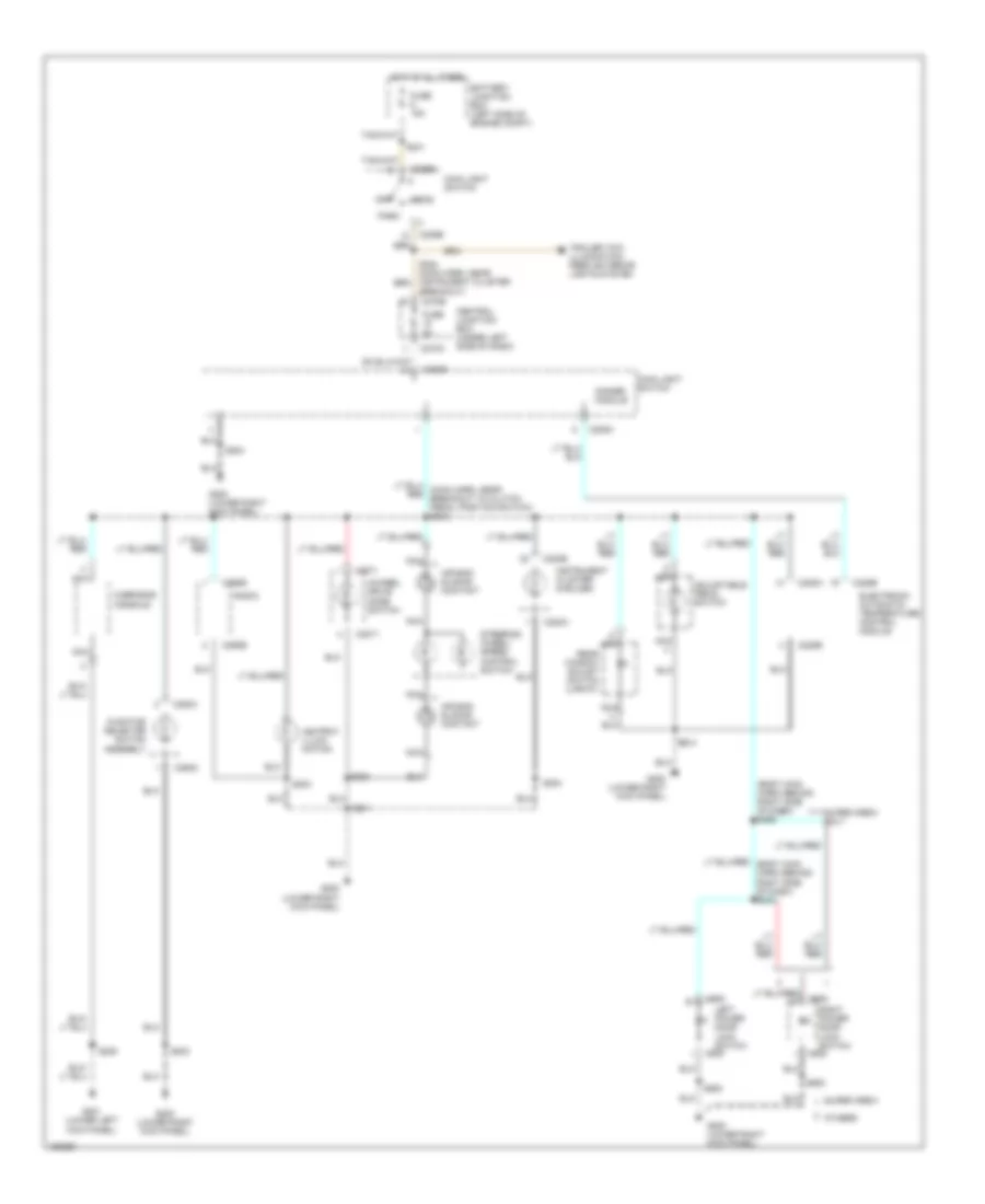 https://portal-diagnostov.com/license.html
Automotive Electricians Portal FZCO
Automotive Electricians Portal FZCO
https://portal-diagnostov.com/license.html
https://portal-diagnostov.com/license.html
Automotive Electricians Portal FZCO
Automotive Electricians Portal FZCOList of elements for Instrument Illumination Wiring Diagram (1 of 2) for Ford Pickup F150 2002:
- (body main harn/ behind right side of dash) s256
- 4wheel drive mode switch
- Adjustable pedal switch
- Air bag sliding contact
- Ashtray illumi- nation
- Battery junction box (left side of engine compt)
- Breakout)
- C205a
- C205b
- C2071
- C220a
- C220b
- C228a
- C228b
- C270a
- C270b
- C290b
- C294c
- C505
- C605
- Central junction box (under left side of dash)
- Dimmer module
- Electronic automatic temperature control module
- Function selector switch assembly
- Fuse 15a
- Fuse 5a
- G200 (lower right kick panel)
- G201 (lower left kick panel)
- Head
- Hot at all times
- Instrument cluster (6 bulbs)
- Left power door lock switch
- Main light switch
- Nca
- Off
- Others
- Overhead console
- Park
- Radio
- Rear window adjust switch (lariat)
- Right power door lock switch
- S201
- S202
- S203
- S204
- S208
- S241
- S500
- S600
- Steering wheel/ speed control switch
- Super crew
- Super crew only
- Trailer tow illumination feed/ exterior lights system
Instrument Illumination Wiring Diagram (2 of 2) for Ford Pickup F150 2002
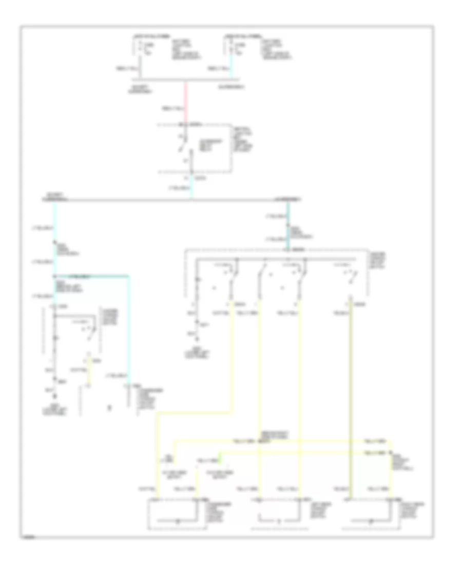 https://portal-diagnostov.com/license.html
Automotive Electricians Portal FZCO
Automotive Electricians Portal FZCO
https://portal-diagnostov.com/license.html
https://portal-diagnostov.com/license.html
Automotive Electricians Portal FZCO
Automotive Electricians Portal FZCOList of elements for Instrument Illumination Wiring Diagram (2 of 2) for Ford Pickup F150 2002:
- (behind right side of dash) s272
- (except supercrew
- (except supercrew)
- (supercrew)
- (w/ keyless entry)
- (w/o keyless entry)
- Accessory delay relay
- Battery junction box (left side of engine compt)
- C270a
- C504a
- C504b
- C535
- C604
- C701
- C801
- Central junction box (under left side of dash)
- Fuse 15a
- G200 (lower left kick panel)
- Hot at all times
- Left rear window adjust switch
- Master window adjust switch
- Passenger side window adjust switch
- Right rear window adjust switch
- S230 (near glove box)
- S248 (behind left side of dash)
- S263 (in right front footwell)
- S271
- S500
POWER DISTRIBUTION
Power Distribution Wiring Diagram (1 of 4) for Ford Pickup F150 2002
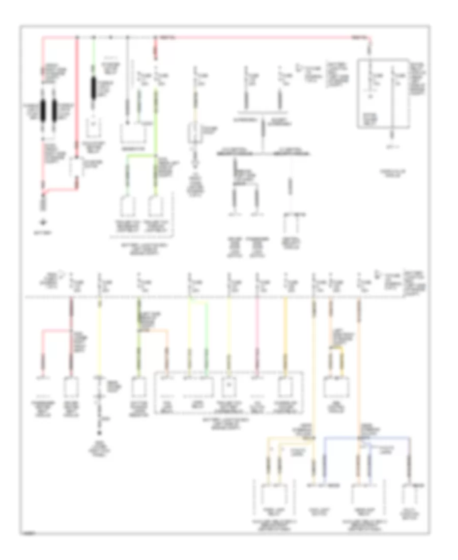 https://portal-diagnostov.com/license.html
Automotive Electricians Portal FZCO
Automotive Electricians Portal FZCO
https://portal-diagnostov.com/license.html
https://portal-diagnostov.com/license.html
Automotive Electricians Portal FZCO
Automotive Electricians Portal FZCOList of elements for Power Distribution Wiring Diagram (1 of 4) for Ford Pickup F150 2002:
- (behind left side of dash) s216
- (front right side of engine red compt) s1001
- (left side front of engine compt) s171
- (left side rear of engine compt) s109
- (near steering column) s212
- (near steering column) s241
- A/c clutch relay
- Abs control module
- Auxiliary relay box 3 (behind right center of dash)
- Battery
- Battery junction box (left side of engine compt)
- Bi-fuel power relay
- Bi-fuel relay module (rear left side of engine compt)
- C102a
- C202b
- C205b
- C274b
- Central security module
- Charge air cooler pump relay
- Cold start heater relay
- Compuvalve module
- Daytime running lamps resistor
- Driver heated seat module
- Driver side door lock switch
- Except supercrew
- Fog lamp relay
- From a fuse 8 (diagram 1 of 4)
- Fuse 10a
- Fuse 15a
- Fuse 20a
- Fuse 30a
- Fuse 3a
- Fuse 50a
- G200
- G200 (lower right kick panel)
- Generator
- Headlamp relay
- Horn relay
- Main light switch
- Multi- function switch
- Park lamp relay
- Passenger heated seat module
- Passenger side door lock switch
- Power point
- Rear power point
- Red
- S1002 (front right side of engine compt)
- S108 (rear left side of engine compt)
- S320 (under right front seat)
- Starter motor
- Starter motor relay
- Supercrew
- To front cigar lighter (diagram 3 of 4)
- To fuse (diagram 1 of 4)
- To fuse (diagram 2 of 4)
- Trailer tow battery charge relay
- Trailer tow parking lamp relay
- Trailer tow reversing lamp relay
- W/ central security module
- W/auto lamps
- W/o central security module
Power Distribution Wiring Diagram (2 of 4) for Ford Pickup F150 2002
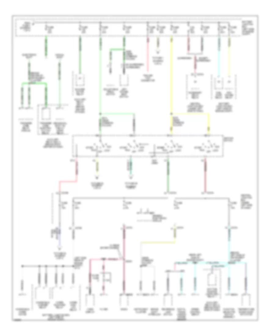 https://portal-diagnostov.com/license.html
Automotive Electricians Portal FZCO
Automotive Electricians Portal FZCO
https://portal-diagnostov.com/license.html
https://portal-diagnostov.com/license.html
Automotive Electricians Portal FZCO
Automotive Electricians Portal FZCOList of elements for Power Distribution Wiring Diagram (2 of 4) for Ford Pickup F150 2002:
- (behind center of instrument cluster) s213
- (behind left side of instrument cluster s222
- (diagram 3 of 4)
- (left side rear of engine compt) s113
- (near steering column) s265
- (not used)
- (rear left side of engine compt) s112
- 7.5a
- A/t
- Acc
- Accessory delay relay
- Adjustable pedal switch
- Auxiliary relay box 2 (behind right side of dash)
- Auxiliary relay box 3 (behind right center of dash)
- Auxiliary relay box 4 (behind center of dash)
- Battery junction box (left side of engine compt)
- Blower motor relay
- Brake shift interlock
- C.b. 30a
- C220a
- C267
- C270a
- C270b
- C290b
- C294a
- Central junction box (under left side of dash)
- Daytime running lamps (drl) relay 1
- Digital trans- mission range sensor
- Electronic shift
- Ex supercrew supercrew
- Except supercrew
- Filter
- From b fuse 3 (diagram 1 of 4)
- Fuel pump relay
- Function selector switch assembly
- Fuse 15a
- Fuse 20a
- Fuse 30a
- Fuse 40a
- Fuse 50a
- Fuse 5a
- Generic electronic module
- Ignition switch
- Inline fuse
- Instrument cluster
- Left power seat switch
- Lock
- M/t
- Manual shift
- Mechanical shift on the fly (msof) relay
- Nca
- Off
- Pcm power relay
- Pnk
- Radio
- Red
- Reversing lamp switch
- Run
- S2003
- S214 (near steering column)
- S215 (near steering column)
- Speed control servo
- Start
- Start start
- Supercrew
- Temperature blend door actuator
- To fuse 1
- To fuse 20 (diagram 4 of 4)
- To fuse 22 (diagram 4 of 4)
- To fuse 29
- Trailer tow connector
- Transfer case electric clutch relay
- Transfer case relay module
- Video display
- W/ rear entertainment
- Windshield washer relay
- Windshield wiper motor
- Wiper high/ low relay
- Wiper run/park relay
Power Distribution Wiring Diagram (3 of 4) for Ford Pickup F150 2002
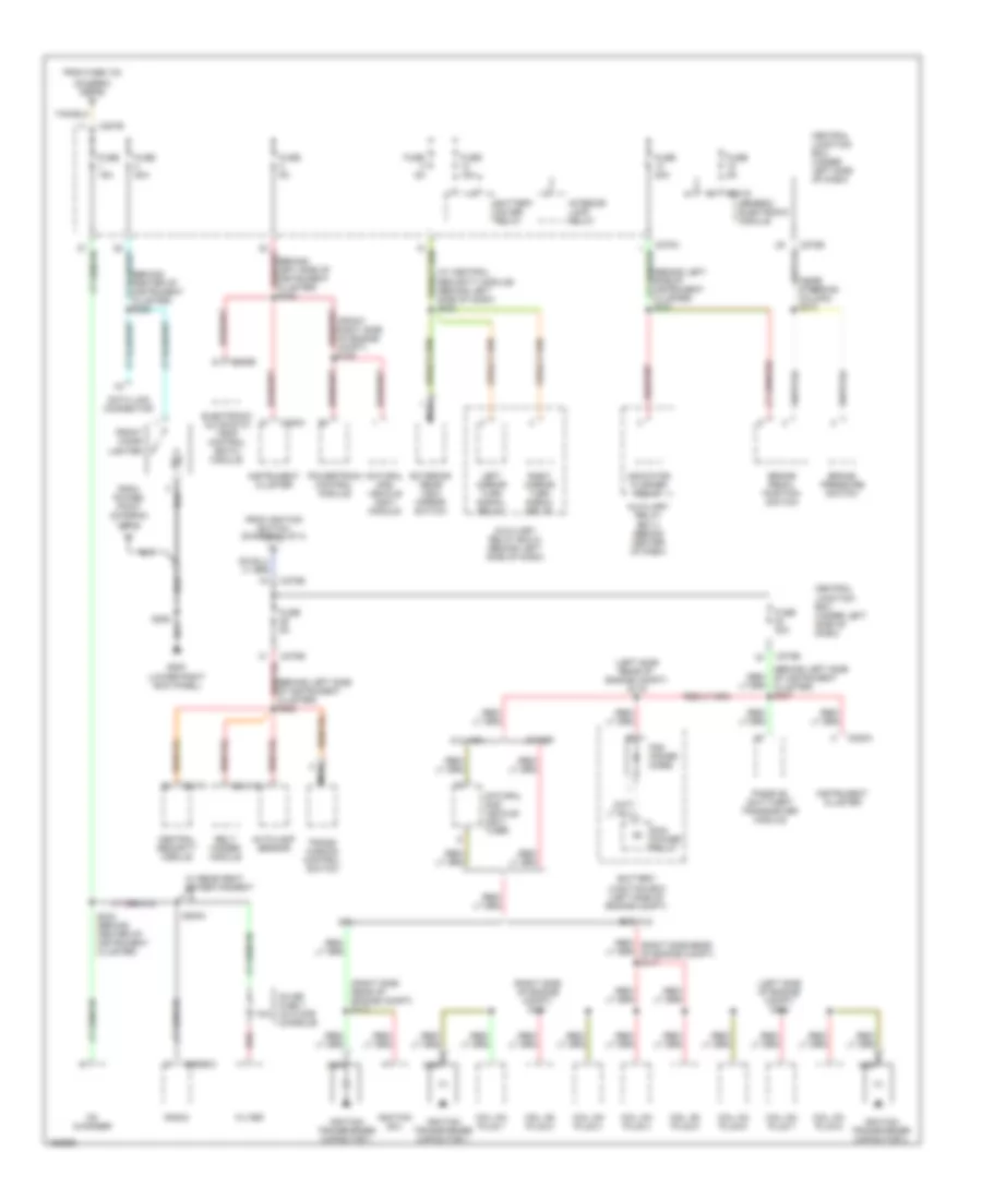 https://portal-diagnostov.com/license.html
Automotive Electricians Portal FZCO
Automotive Electricians Portal FZCO
https://portal-diagnostov.com/license.html
https://portal-diagnostov.com/license.html
Automotive Electricians Portal FZCO
Automotive Electricians Portal FZCOList of elements for Power Distribution Wiring Diagram (3 of 4) for Ford Pickup F150 2002:
- (behind center of instrument cluster) s289
- (behind left side of instrument cluster) s221
- (behind left side of instrument cluster) s225
- (behind left side of instrument cluster) s236
- (behind left side of instrument cluster) s237
- (diagram 2 of 4) c
- (left side of engine compt) s162
- (left side rear of engine compt) s116
- (near steering column) s274
- (right side of engine compt) s161
- (right side rear of engine compt) s117
- (w/ central security module) (behind left side of dash) s220
- 4.2l
- 5.4l ngv
- 7.5a
- Autolamp sensor
- Auxiliary relay box 4 (behind center of dash)
- Auxiliary relay box 5 (behind left side of dash)
- Battery junction box (left side of engine compt)
- Battery saver relay
- Belt minder module
- Brake pedal position switch
- Brake pressure switch
- C201d
- C2031b
- C207b
- C220a
- C228b
- C247a
- C270b
- C290b/c
- Cd changer
- Central junction box (under left side of dash)
- Central security module
- Coil on plug 1
- Coil on plug 2
- Coil on plug 3
- Coil on plug 4
- Coil on plug 5
- Coil on plug 6
- Coil on plug 7
- Coil on plug 8
- Data link connector
- Electronic automatic temp control (eatc) module
- Exc 4.2l
- Exterior rear view mirror switch
- Filter
- From fuse 103
- From ignition switch (diagram 2 of 4)
- From power point (diagram 1 of 4)
- Front cigar lighter
- Fuse 15a
- Fuse 20a
- Fuse 30a
- Fuse 5a
- G200 (lower right kick panel)
- Generic electronic module
- Ignition coil
- Ignition transformer capacitor 1
- Ignition transformer capacitor 2
- Indicator flasher relay
- Inline fuse 1 (in floor console)
- Instrument cluster
- Interior lamp relay
- Left mirror turn signal relay
- Natural gas vehicle (ngv) module
- Natural gas vehicle (ngv) timer
- Nca
- Other
- Passive anit-theft transceiver module
- Pcm power diode
- Pcm power relay
- Powertrain control module
- Radio
- Red
- Red/ (right side rear of engine compt) s117
- Right mirror turn signal relay
- S158
- S2004
- S205
- S233 (behind center of instrument cluster)
- Trans- mission control switch
- W/ rear seat entertainment
Power Distribution Wiring Diagram (4 of 4) for Ford Pickup F150 2002
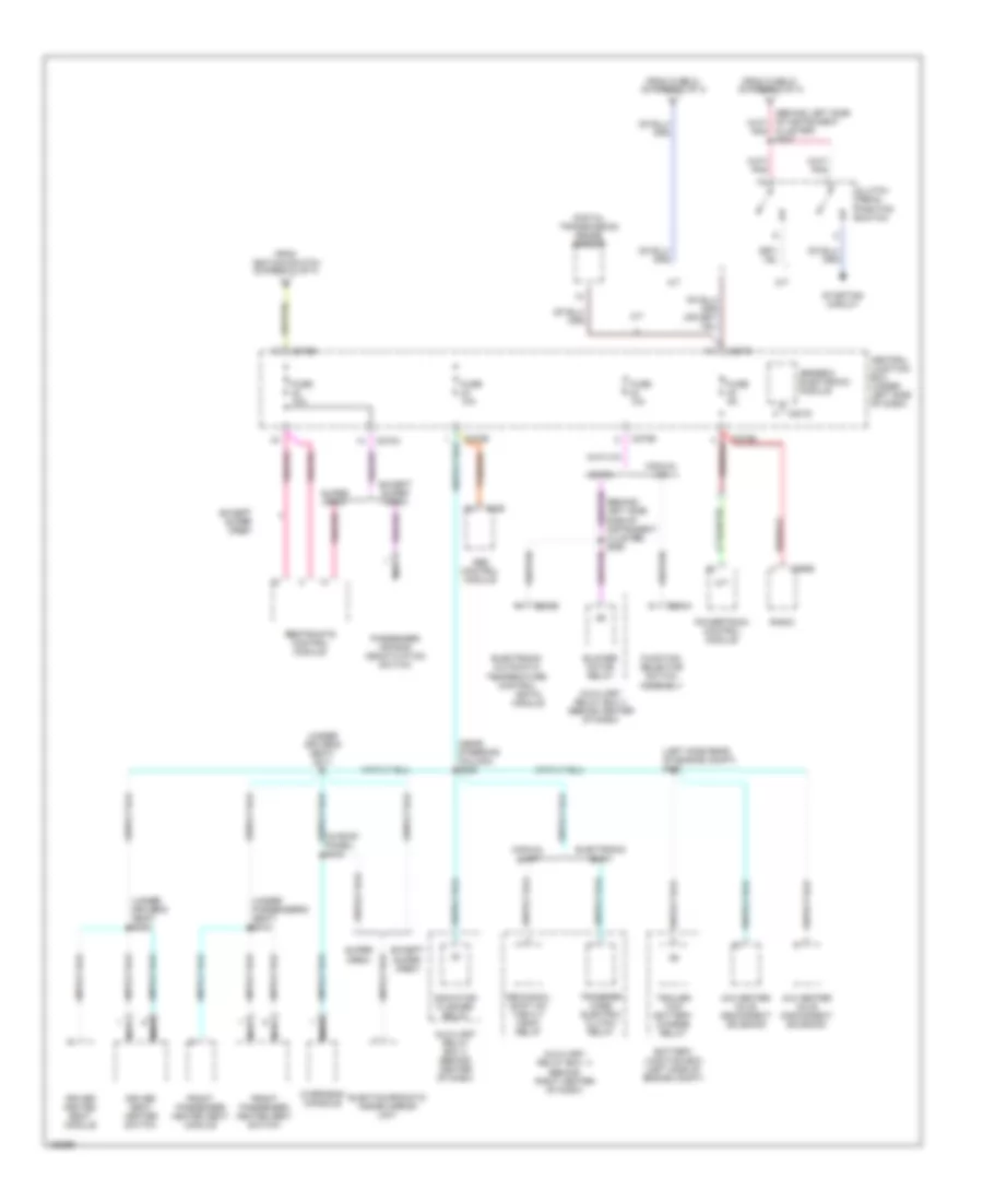 https://portal-diagnostov.com/license.html
Automotive Electricians Portal FZCO
Automotive Electricians Portal FZCO
https://portal-diagnostov.com/license.html
https://portal-diagnostov.com/license.html
Automotive Electricians Portal FZCO
Automotive Electricians Portal FZCOList of elements for Power Distribution Wiring Diagram (4 of 4) for Ford Pickup F150 2002:
- (eatc) module
- (left side rear of engine compt) s120
- (near steering column) s228
- (under driver's seat) s300
- (under driver's seat) s311
- (under passenger's seat) s310
- 4x2 center axle disconnect solenoid
- 4x4 center axle disconnect solenoid
- A/t
- Abs control module
- Auxiliary relay box 3 (behind right center of dash)
- Auxiliary relay box 4 (behind center of dash)
- Battery junction box (left side of engine compt)
- Blower motor relay
- C155
- C201d
- C207b
- C228b
- C270a
- C270b
- C290b
- C294a
- Central junction box (under left side of dash)
- Cluster) s227
- Clutch pedal position switch
- Digital transmission range sensor
- Driver heated seat module
- Driver seat heater switch
- Eatc
- Electochromatic inside mirror unit
- Electronic automatic temperature control
- Electronic shift
- Except super crew
- From fuse 21 (diagram 2 of 4)
- From ignition switch (diagram 2 of 4)
- Front passenger heated seat module
- Front passenger heated seat switch
- Function selector switch assembly
- Fuse 10a
- Fuse 5a
- Generic electronic module
- Indicator flasher relay
- M/t
- Manual a/c
- Manual shift
- Mechanicl shift on the fly msof) relay
- Nca
- Overhead console
- Passenger air bag deactivation switch
- Powertrain control module
- Radio
- Restraints control module
- Starting circuit
- Super crew
- Tan/red
- Trailer tow battery charge relay
- Transfer case electric clutch relay
POWER DOOR LOCKS
Door Lock Wiring Diagram for Ford Pickup F150 2002
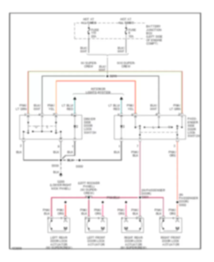 https://portal-diagnostov.com/license.html
Automotive Electricians Portal FZCO
Automotive Electricians Portal FZCO
https://portal-diagnostov.com/license.html
https://portal-diagnostov.com/license.html
Automotive Electricians Portal FZCO
Automotive Electricians Portal FZCOList of elements for Door Lock Wiring Diagram for Ford Pickup F150 2002:
- (in passenger door) s601
- (in passenger door) s602
- (left rocker panel) (w/ super- crew) s273
- Battery junction box (left side of engine compt)
- Driver side door lock switch
- Fuse 15a
- Fuse 20a
- G200 (lower right kick panel)
- Hot at all times
- Interior lights system
- Left front door lock actuator
- Left rear door lock actuator (w/ supercrew)
- Pass- enger side door lock switch
- Right front door lock actuator
- Right rear door lock actuator (w/ supercrew)
- S216
- S500
- S600
- W/ super- crew
- W/o super- crew
Keyless Entry Wiring Diagram, with Analog Keypad for Ford Pickup F150 2002
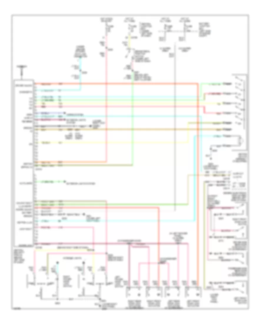 https://portal-diagnostov.com/license.html
Automotive Electricians Portal FZCO
Automotive Electricians Portal FZCO
https://portal-diagnostov.com/license.html
https://portal-diagnostov.com/license.html
Automotive Electricians Portal FZCO
Automotive Electricians Portal FZCOList of elements for Keyless Entry Wiring Diagram, with Analog Keypad for Ford Pickup F150 2002:
- (behind right side of dash)
- (in left rocker panel) (w/ super- crew) s273
- (in passenger door) s601
- (in passenger door) s602
- (in right front footwell) (w/ super- crew)
- (lower right kick panel)
- (lower right kick panel) g200
- (under center of dash) data link connector
- (w/ super crew)
- (w/ supercrew)
- (w/o super crew)
- 1/2
- 3/4
- 5/6
- 7/8
- 9/0
- Ajar in
- Ajar out
- Antenna
- Autolamps
- Battery
- Battery junction box (left side of engine compt)
- Bpp sw in
- Brake pedal position switch (under left side of dash)
- C201a
- C201b
- C270b
- C274a
- C274b
- Central junction box (under left side of dash)
- Central security module (behind left side of dash)
- Diagnostic
- Door ajar
- Doors lock
- Doors unlock
- Driver side rear door ajar switch
- Driver unlock
- Exterior lights system
- Fuse 15a
- Fuse 20a
- Fuse 5a
- G200
- G200 (lower right kick panel)
- G201 (lower left kick panel)
- Generic electronic module (gem) (behind left side of dash)
- Ground
- Horn
- Horns system
- Hot at all times
- Hot in run or start
- Ignition
- Illum entry
- Illum in
- Interior lights
- Keypad illum
- Keypad switch assembly (if equipped)
- Left front door ajar switch
- Left front door lock actuator
- Left power door lock switch
- Left rear door lock actuator (w/ supercrew)
- Lft
- Lock
- Lock in/out
- Nca
- Passenger side rear door ajar switch
- Red
- Reverse
- Right front door ajar switch
- Right front door lock actuator
- Right power door lock switch
- Right rear door lock actuator (w/ supercrew)
- S203
- S204
- S208
- S225
- S229
- S234
- S235 (behind right side of dash)
- S260
- S261
- S297 (behind left side of instru- ment cluster)
- S500
- S501
- S600
- S774
- S864
- Unlk
- Unlock in/out
- W/ super- crew
- W/o super- crew
Keyless Entry Wiring Diagram, with Digital Keypad for Ford Pickup F150 2002
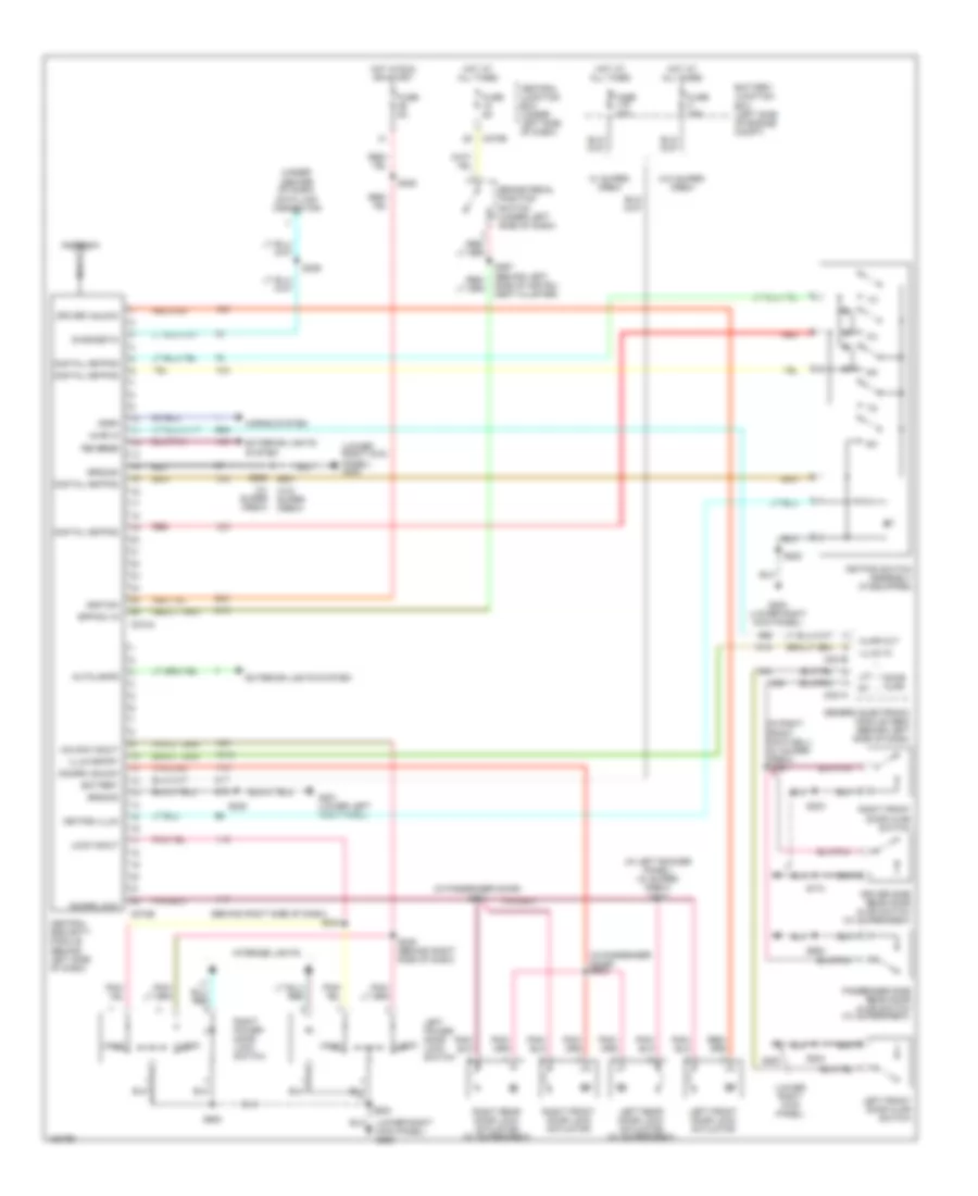 https://portal-diagnostov.com/license.html
Automotive Electricians Portal FZCO
Automotive Electricians Portal FZCO
https://portal-diagnostov.com/license.html
https://portal-diagnostov.com/license.html
Automotive Electricians Portal FZCO
Automotive Electricians Portal FZCOList of elements for Keyless Entry Wiring Diagram, with Digital Keypad for Ford Pickup F150 2002:
- (behind right side of dash)
- (in left rocker panel) (w/ super- crew) s273
- (in passenger door) s601
- (in passenger door) s602
- (in right front footwell) (w/ super- crew)
- (lower right kick panel)
- (lower right kick panel) g200
- (under center of dash) data link connector
- (w/ super crew)
- (w/ supercrew)
- (w/o super crew)
- 1/2
- 3/4
- 5/6
- 7/8
- 9/0
- Ajar in
- Ajar out
- Antenna
- Autolamps
- Battery
- Battery junction box (left side of engine compt)
- Bpp sw in
- Brake pedal position switch (under left side of dash)
- C201a
- C201b
- C270b
- C274a
- C274b
- Central junction box (under left side of dash)
- Central security module (behind left side of dash)
- Diagnostic
- Digital keypad
- Door ajar
- Doors lock
- Doors unlock
- Driver side rear door ajar switch
- Driver unlock
- Exterior lights system
- Fuse 15a
- Fuse 20a
- Fuse 5a
- G200
- G200 (lower right kick panel)
- G201 (lower left kick panel)
- Generic electronic module (gem) (behind left side of dash)
- Ground
- Horn
- Horns system
- Hot at all times
- Hot in run or start
- Ignition
- Illum entry
- Illum in
- Interior lights
- Keypad illum
- Keypad switch assembly (if equipped)
- Left front door ajar switch
- Left front door lock actuator
- Left power door lock switch
- Left rear door lock actuator (w/ supercrew)
- Lft
- Lock
- Lock in/out
- Nca
- Passenger side rear door ajar switch
- Red
- Reverse
- Right front door ajar switch
- Right front door lock actuator
- Right power door lock switch
- Right rear door lock actuator (w/ supercrew)
- S203
- S204
- S208
- S225
- S229
- S234
- S235 (behind right side of dash)
- S260
- S261
- S297 (behind left side of instru- ment cluster)
- S500
- S501
- S600
- S774
- S864
- Unlk
- Unlock in/out
- W/ super- crew
- W/o super- crew
POWER MIRRORS
Power Mirror Wiring Diagram for Ford Pickup F150 2002
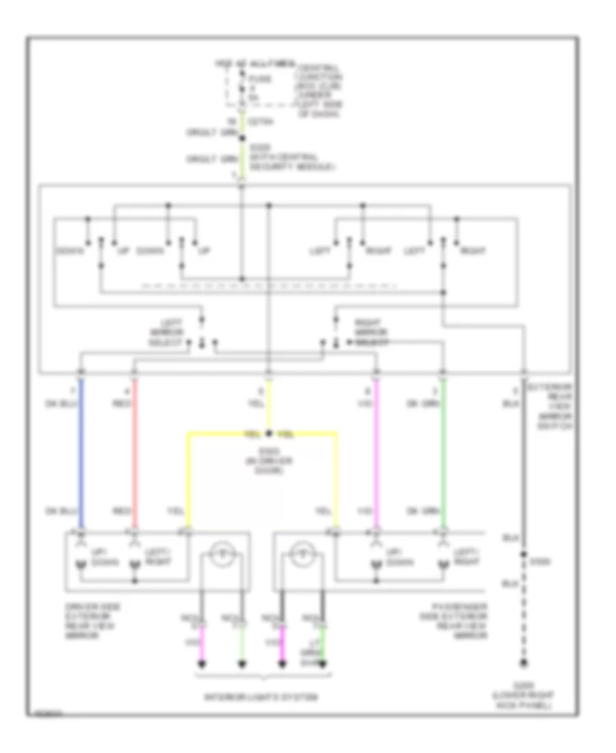 https://portal-diagnostov.com/license.html
Automotive Electricians Portal FZCO
Automotive Electricians Portal FZCO
https://portal-diagnostov.com/license.html
https://portal-diagnostov.com/license.html
Automotive Electricians Portal FZCO
Automotive Electricians Portal FZCOList of elements for Power Mirror Wiring Diagram for Ford Pickup F150 2002:
- C270a
- Central junction box (cjb) (under left side of dash)
- Down
- Driver side exterior rear view mirror
- Exterior rear view mirror switch
- Fuse 5a
- G200 (lower right kick panel)
- Hot at all times
- Interior lights system
- Left
- Left mirror select
- Left/ right
- Nca
- Passenger side exterior rear view mirror
- Red
- Right
- Right mirror select
- S220 (with central security module)
- S500
- S503 (in driver door)
- Up/ down m
POWER SEATS
Adjustable Pedal Wiring Diagram for Ford Pickup F150 2002
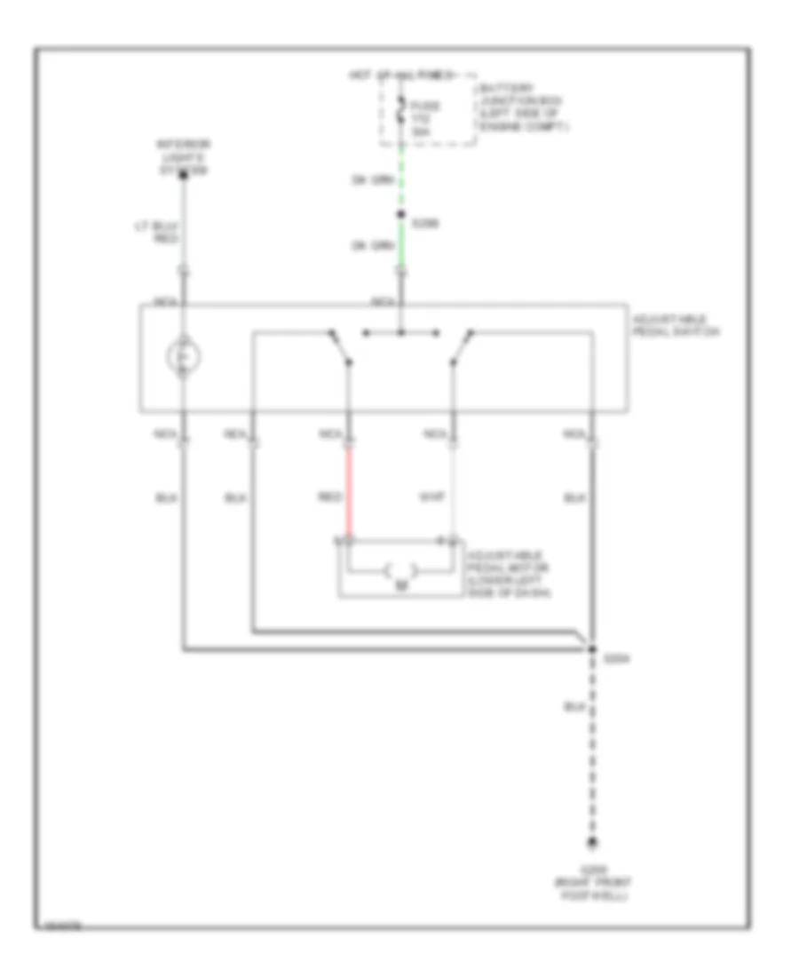 https://portal-diagnostov.com/license.html
Automotive Electricians Portal FZCO
Automotive Electricians Portal FZCO
https://portal-diagnostov.com/license.html
https://portal-diagnostov.com/license.html
Automotive Electricians Portal FZCO
Automotive Electricians Portal FZCOList of elements for Adjustable Pedal Wiring Diagram for Ford Pickup F150 2002:
- Adjustable pedal motor (lower left side of dash)
- Adjustable pedal switch
- Battery junction box (left side of engine compt)
- Fuse 30a
- G200 (right front footwell)
- Hot at all times
- Interior lights system
- Nca
- Red
- S204
- S298
Driver Power Seat Wiring Diagram for Ford Pickup F150 2002
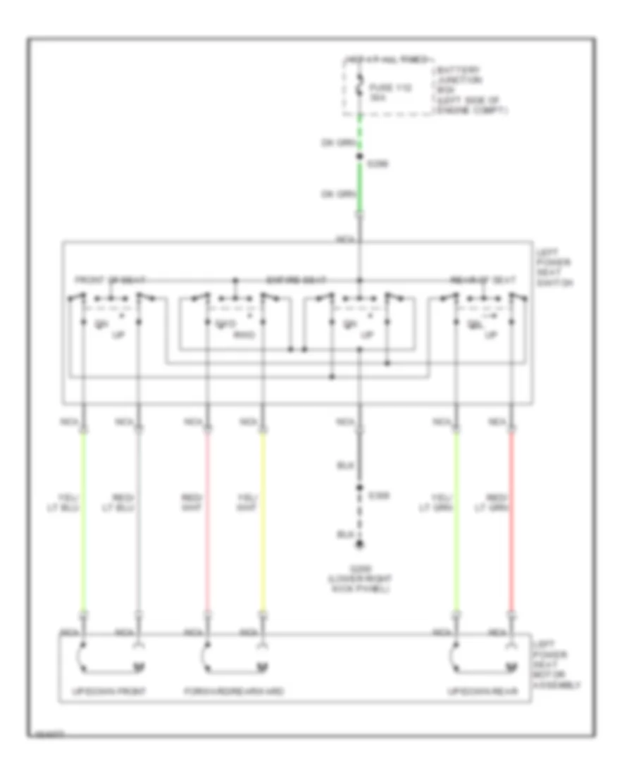 https://portal-diagnostov.com/license.html
Automotive Electricians Portal FZCO
Automotive Electricians Portal FZCO
https://portal-diagnostov.com/license.html
https://portal-diagnostov.com/license.html
Automotive Electricians Portal FZCO
Automotive Electricians Portal FZCOList of elements for Driver Power Seat Wiring Diagram for Ford Pickup F150 2002:
- Battery junction box (left side of engine compt)
- Entire seat
- Forward/rearward
- Front of seat
- Fuse 112 30a
- Fwd
- G200 (lower right kick panel)
- Hot at all times
- Left power seat motor assembly
- Left power seat switch
- Nca
- Rear of seat
- Rwd
- S298
- S306
- Up/down front
- Up/down rear
Heated Seats Wiring Diagram for Ford Pickup F150 2002
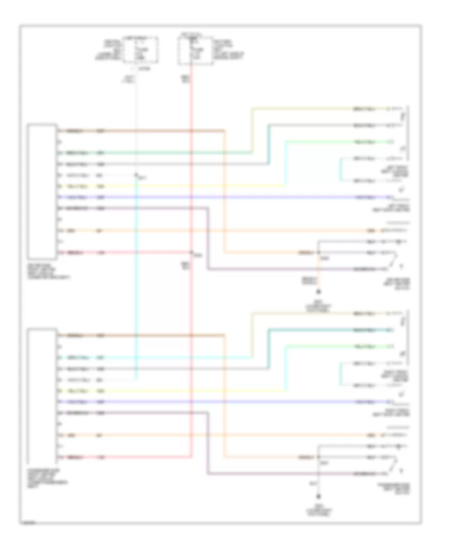 https://portal-diagnostov.com/license.html
Automotive Electricians Portal FZCO
Automotive Electricians Portal FZCO
https://portal-diagnostov.com/license.html
https://portal-diagnostov.com/license.html
Automotive Electricians Portal FZCO
Automotive Electricians Portal FZCOList of elements for Heated Seats Wiring Diagram for Ford Pickup F150 2002:
- (lower right kick panel)
- Battery junction box (in left side of engine compt)
- C270b
- Central junction box (under left side of dash)
- Driver side front heated seat module (under driver's seat)
- Driver side seat heater switch
- Fuse 10a
- Fuse 30a
- G200
- Hot at all times
- Hot in run
- Left front seat back heater
- Left front seat cushion heater
- Passenger side front heated seat module (under passenger's seat)
- Passenger side seat heater switch
- Right front seat back heater
- Right front seat cushion heater
- S306
- S311
- S320
- S321
POWER TOP/SUNROOF
Power Top/Sunroof Wiring Diagrams for Ford Pickup F150 2002
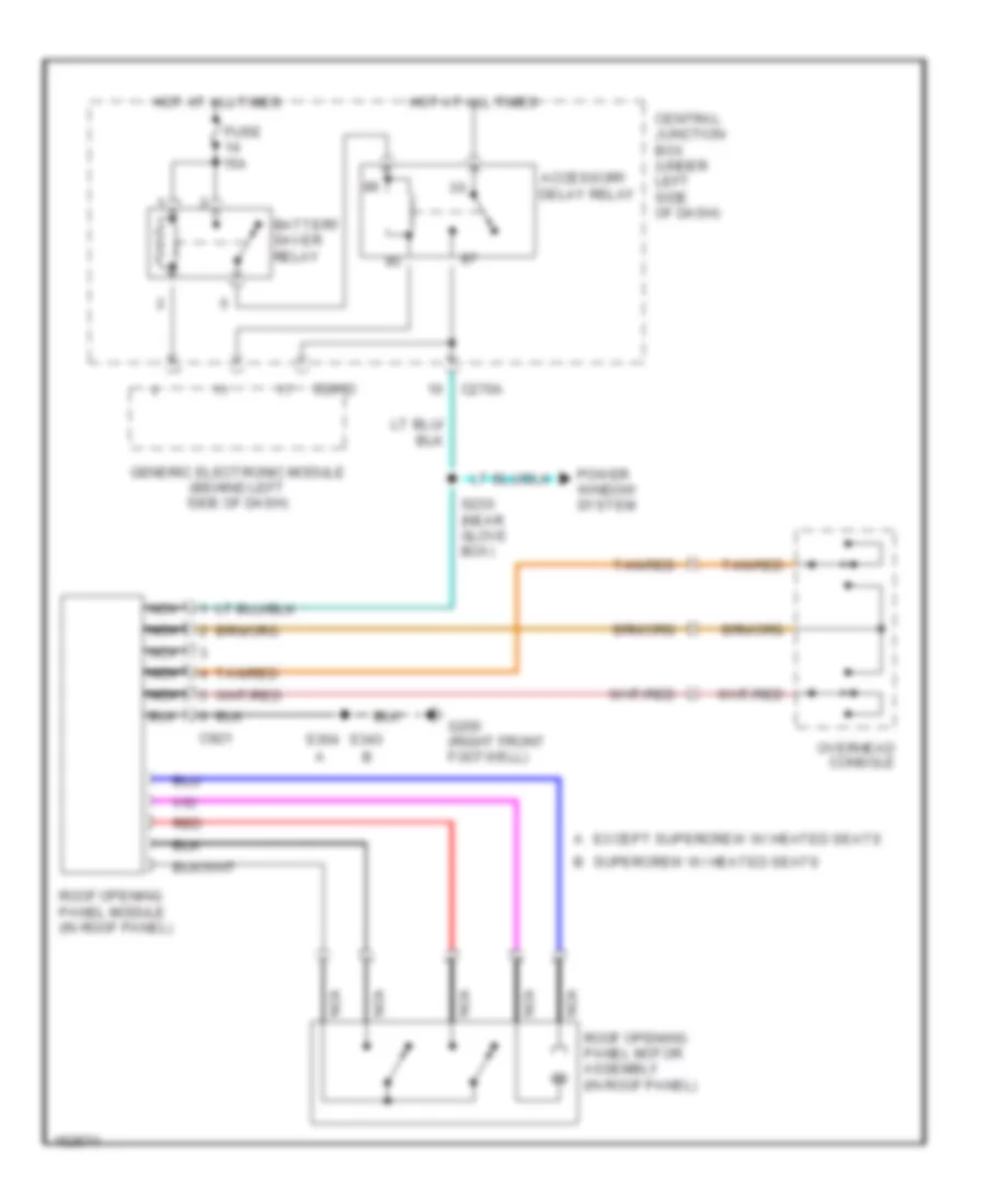 https://portal-diagnostov.com/license.html
Automotive Electricians Portal FZCO
Automotive Electricians Portal FZCO
https://portal-diagnostov.com/license.html
https://portal-diagnostov.com/license.html
Automotive Electricians Portal FZCO
Automotive Electricians Portal FZCOList of elements for Power Top/Sunroof Wiring Diagrams for Ford Pickup F150 2002:
- A except supercrew w/ heated seats
- Accessory delay relay
- B supercrew w/ heated seats
- Battery saver relay
- C201d
- C270a
- C921
- Central junction box (under left side of dash)
- Fuse 15a
- G200 (right front footwell)
- Generic electronic module (behind left side of dash)
- Hot at all times
- Nca
- Overhead console
- Power window system
- Red
- Roof opening panel module (in roof panel)
- Roof opening panel motor assembly (in roof panel)
- S230 (near glove box)
- S343 s304
- Tan/red
POWER WINDOWS
Power Window Wiring Diagram, Except Supercrew for Ford Pickup F150 2002
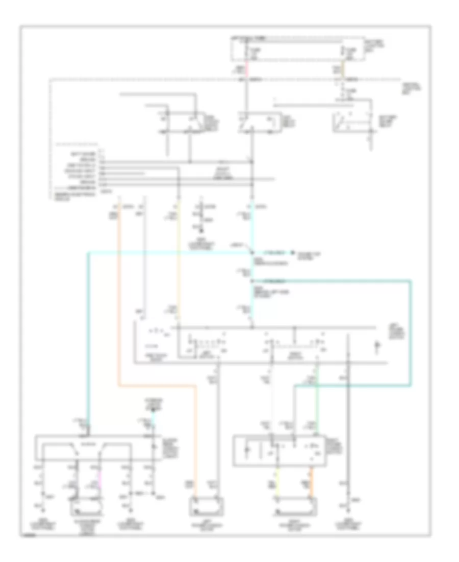 https://portal-diagnostov.com/license.html
Automotive Electricians Portal FZCO
Automotive Electricians Portal FZCO
https://portal-diagnostov.com/license.html
https://portal-diagnostov.com/license.html
Automotive Electricians Portal FZCO
Automotive Electricians Portal FZCOList of elements for Power Window Wiring Diagram, Except Supercrew for Ford Pickup F150 2002:
- 87a
- Acc delay relay
- Batt saver
- Battery junction box
- Battery saver relay
- C201d
- C270a
- C270b
- Central junction box
- Down sw input
- Fuse 15a
- Fuse 30a
- Fuse 50a
- G200 (lower right kick panel)
- Generic electronic module
- Ground
- Hot at all times
- Interior lights system
- Lariat
- Left power window motor
- Left power window switch
- Left switch
- Nca
- One tch dn hi
- One tch dn lo
- One touch down
- One touch down relay
- Otd sw input
- Power top system
- Right power window motor
- Right power window switch
- Right switch
- S201
- S204
- S205
- S230 (near glove box)
- S248 (behind left side of dash)
- S500
- Shunt (0.015 +/- 0.001 ohm)
- Sliding rear window motor (lariat)
- Sliding rear window switch (lariat)
Power Window Wiring Diagram, Supercrew for Ford Pickup F150 2002
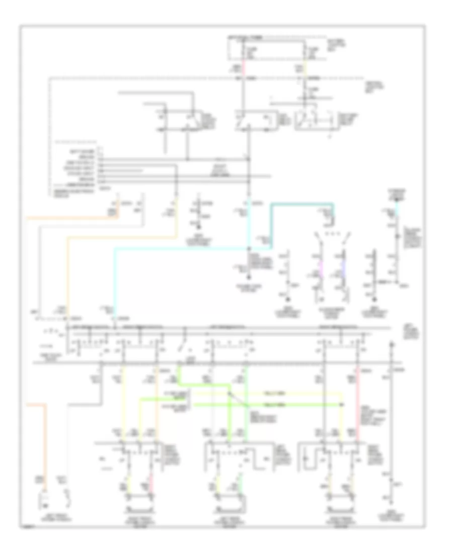 https://portal-diagnostov.com/license.html
Automotive Electricians Portal FZCO
Automotive Electricians Portal FZCO
https://portal-diagnostov.com/license.html
https://portal-diagnostov.com/license.html
Automotive Electricians Portal FZCO
Automotive Electricians Portal FZCOList of elements for Power Window Wiring Diagram, Supercrew for Ford Pickup F150 2002:
- 87a
- Acc delay relay
- Batt saver
- Battery junction box
- Battery saver relay
- C201d
- C242
- C270a
- C270b
- C504a
- C504b
- Central junction box
- Down sw input
- Fuse 15a
- Fuse 30a
- Fuse 50a
- G200 (lower right kick panel)
- Generic electronic module
- Ground
- Hot at all times
- Interior lights system
- Left front power window
- Left front switch
- Left power window switch
- Left rear power window motor
- Left rear power window switch
- Left rear switch
- Lock out
- Nca
- One tch dn hi
- One tch dn lo
- One touch down
- One touch down relay
- Otd sw input
- Power tops system
- Right front power window motor
- Right front power window switch
- Right front switch
- Right rear power window motor
- Right rear power window switch
- Right rear switch
- S201
- S204
- S205
- S230 (main harn, near right kick panel)
- S263 w/o keyless entry (right front footwell)
- S271
- S272 (behind right side of dash)
- Shunt (0.015 +/- 0.001 ohm)
- Sliding rear window motor
- Sliding rear window switch (lariat)
- W/ keyless entry
- W/o keyless entry
RADIO
Base Radio for Ford Pickup F150 2002
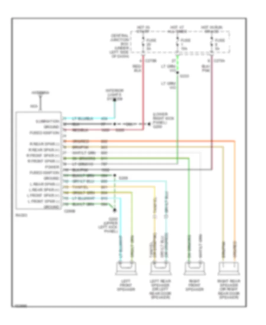 https://portal-diagnostov.com/license.html
Automotive Electricians Portal FZCO
Automotive Electricians Portal FZCO
https://portal-diagnostov.com/license.html
https://portal-diagnostov.com/license.html
Automotive Electricians Portal FZCO
Automotive Electricians Portal FZCOList of elements for Base Radio for Ford Pickup F150 2002:
- (lower right kick panel) g200
- Antenna
- C270a
- C270b
- C290b
- Central junction box (under left side of dash)
- Fuse 15a
- Fuse 5a
- Fused ignition
- G202 (upper left kick panel)
- Ground
- Hot at all times
- Hot in run or acc
- Hot in start
- Ilumination
- Interior lights system
- L front spkr (+)
- L front spkr (-)
- L rear spkr (+)
- L rear spkr (-)
- Left front speaker
- Left rear speaker (or left rear door speaker)
- Nca
- Power
- R front spkr (+)
- R front spkr (-)
- R rear spkr (+)
- R rear spkr (-)
- Radio
- Right front speaker
- Right rear speaker (or right rear door speaker)
- S203
- S209
- S233
Premium Sound Radio Wiring Diagram, with Rear Entertainment (1 of 2) for Ford Pickup F150 2002
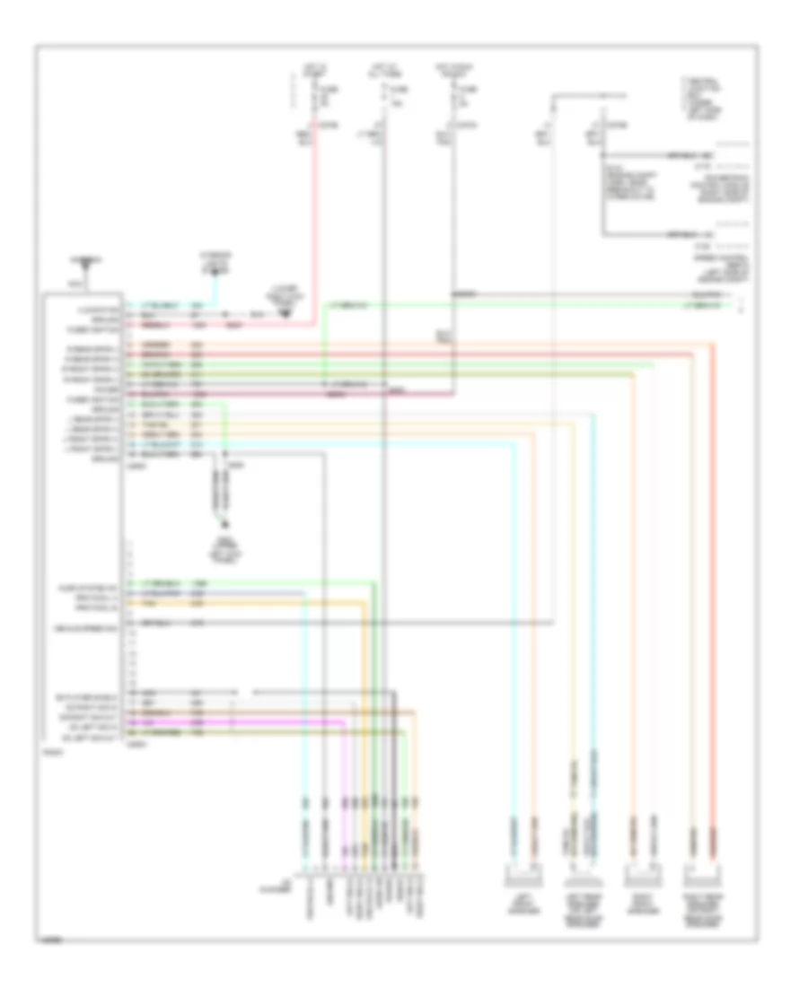 https://portal-diagnostov.com/license.html
Automotive Electricians Portal FZCO
Automotive Electricians Portal FZCO
https://portal-diagnostov.com/license.html
https://portal-diagnostov.com/license.html
Automotive Electricians Portal FZCO
Automotive Electricians Portal FZCOList of elements for Premium Sound Radio Wiring Diagram, with Rear Entertainment (1 of 2) for Ford Pickup F150 2002:
- (lower right kick panel) g200
- Antenna
- Audio on
- Audio system on
- C122
- C175
- C270a
- C270b
- C290a
- C290c
- Cd changer
- Cd left sig in
- Cd left sig out
- Cd player shield
- Cd right sig in
- Cd right sig out
- Central junction box (under left side of dash)
- Fuse 15a
- Fuse 5a
- Fused ignition
- G202 (upper left kick panel)
- Ground
- Hot at all times
- Hot in run or acc
- Hot in start
- Ilumination
- Interior lights system
- L front spkr (+)
- L front spkr (-)
- L rear spkr (+)
- L rear spkr (-)
- Left front speaker
- Left rear speaker (or left rear door speaker)
- Left sig (+)
- Left sig (-)
- Nca
- Power
- Powertrain control module (right side of engine compt)
- Protocol a
- Protocol b
- R front spkr (+)
- R front spkr (-)
- R rear spkr (+)
- R rear spkr (-)
- Radio
- Right front speaker
- Right rear speaker (or right rear door speaker)
- Right sig (+)
- Right sig (-)
- S143 (engine compt harn, near breakout to wiper motor)
- S2003
- S2004
- S203
- S209
- S233
- Shield
- Speed control servo (left side of engine compt)
- Tan
- Vehicle speed sig
Premium Sound Radio Wiring Diagram, with Rear Entertainment (2 of 2) for Ford Pickup F150 2002
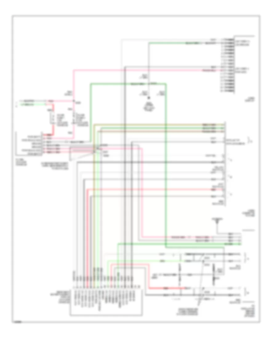 https://portal-diagnostov.com/license.html
Automotive Electricians Portal FZCO
Automotive Electricians Portal FZCO
https://portal-diagnostov.com/license.html
https://portal-diagnostov.com/license.html
Automotive Electricians Portal FZCO
Automotive Electricians Portal FZCOList of elements for Premium Sound Radio Wiring Diagram, with Rear Entertainment (2 of 2) for Ford Pickup F150 2002:
- (in rear entertaiment harn, near breakout to rca plugs)
- (not used)
- (radio receiver tuner harness, in floor console)
- Antenna
- Filter (in floor console)
- Fm mod (on/off)
- Fm mod l (+)
- Fm mod l (-)
- Fm mod r (+)
- Fm mod r (-)
- Fm modulator (behind center of dash)
- G202 (upper left kick panel)
- Ground
- I/r plug sleeve
- I/r plug tip
- Inline fuse 1 7.5a (in floor console)
- Inline fuse 2 7.5a (in floor console)
- Ir shield
- Ir signal
- Lcd video (+)
- Lcd video (-)
- Nca
- Nca lcd ground
- Nca lcd video (+)
- Nca lcd video (-)
- Nca pwr (acc)
- Pnk
- Pwr (acc or run)
- Pwr (batt)
- Pwr (run & acc)
- Rear seat entertainment module (in floor console)
- Red
- Red rca plug
- S2002
- S330
- S332
- S333
- S334
- S335
- S355
- S356
- S357
- S358
- Vcp audio l (+)
- Vcp audio l (-)
- Vcp audio r (+)
- Vcp audio r (-)
- Vcp video (+)
- Vcp video (-)
- Video cassette player
- Video display
Premium Sound Radio Wiring Diagram, without Rear Entertainment for Ford Pickup F150 2002
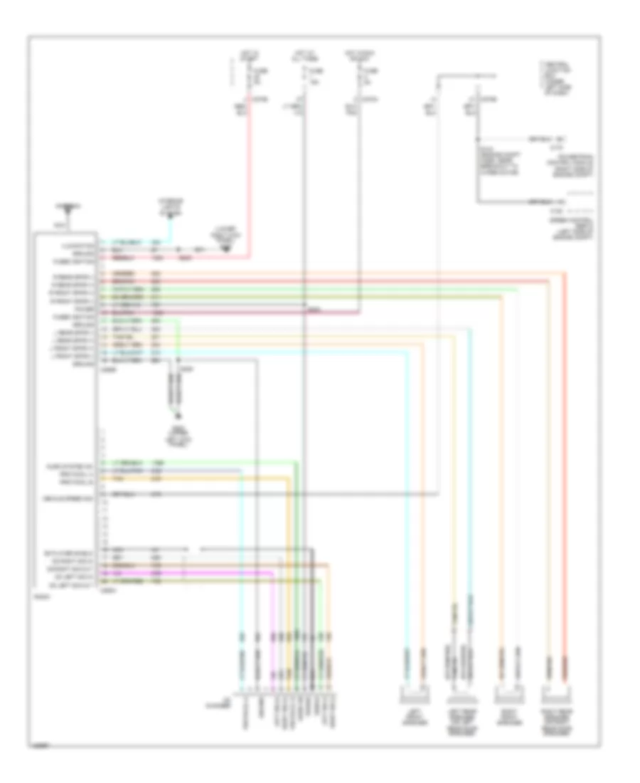 https://portal-diagnostov.com/license.html
Automotive Electricians Portal FZCO
Automotive Electricians Portal FZCO
https://portal-diagnostov.com/license.html
https://portal-diagnostov.com/license.html
Automotive Electricians Portal FZCO
Automotive Electricians Portal FZCOList of elements for Premium Sound Radio Wiring Diagram, without Rear Entertainment for Ford Pickup F150 2002:
- (lower right kick panel) g200
- Antenna
- Audio on
- Audio system on
- C122
- C175
- C270a
- C270b
- C290a
- C290b
- Cd changer
- Cd left sig in
- Cd left sig out
- Cd player shield
- Cd right sig in
- Cd right sig out
- Central junction box (under left side of dash)
- Fuse 15a
- Fuse 5a
- Fused ignition
- G202 (upper left kick panel)
- Ground
- Hot at all times
- Hot in run or acc
- Hot in start
- Ilumination
- Interior lights system
- L front spkr (+)
- L front spkr (-)
- L rear spkr (+)
- L rear spkr (-)
- Left front speaker
- Left rear speaker (or left rear door speaker)
- Left sig (+)
- Left sig (-)
- Nca
- Power
- Powertrain control module (right side of engine compt)
- Protocol a
- Protocol b
- R front spkr (+)
- R front spkr (-)
- R rear spkr (+)
- R rear spkr (-)
- Radio
- Right front speaker
- Right rear speaker (or right rear door speaker)
- Right sig (+)
- Right sig (-)
- S143 (engine compt harn, near breakout to wiper motor)
- S203
- S209
- S233
- Shield
- Speed control servo (left side of engine compt)
- Tan
- Vehicle speed sig
SHIFT INTERLOCKS
Shift Interlock Wiring Diagram for Ford Pickup F150 2002
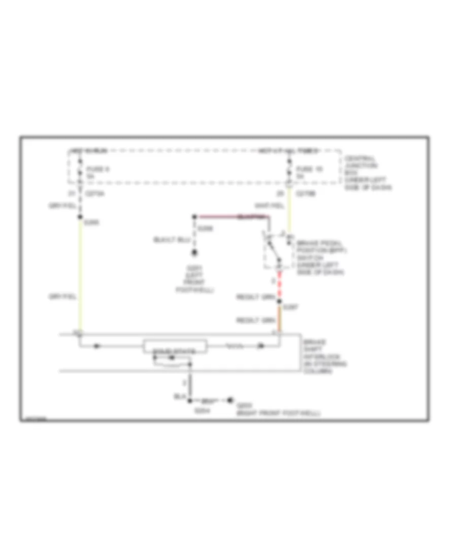 https://portal-diagnostov.com/license.html
Automotive Electricians Portal FZCO
Automotive Electricians Portal FZCO
https://portal-diagnostov.com/license.html
https://portal-diagnostov.com/license.html
Automotive Electricians Portal FZCO
Automotive Electricians Portal FZCOList of elements for Shift Interlock Wiring Diagram for Ford Pickup F150 2002:
- Brake pedal position (bpp) switch (under left side of dash)
- Brake shift interlock (in steering column)
- C270a
- C270b
- Central junction box (under left side of dash)
- Fuse 15 5a
- Fuse 6 5a
- G200 (right front footwell)
- G201 (left front footwell)
- Hot at all times
- Hot in run
- S204
- S208
- S265
- S297
- Solid state
STARTING/CHARGING
Charging Wiring Diagram for Ford Pickup F150 2002
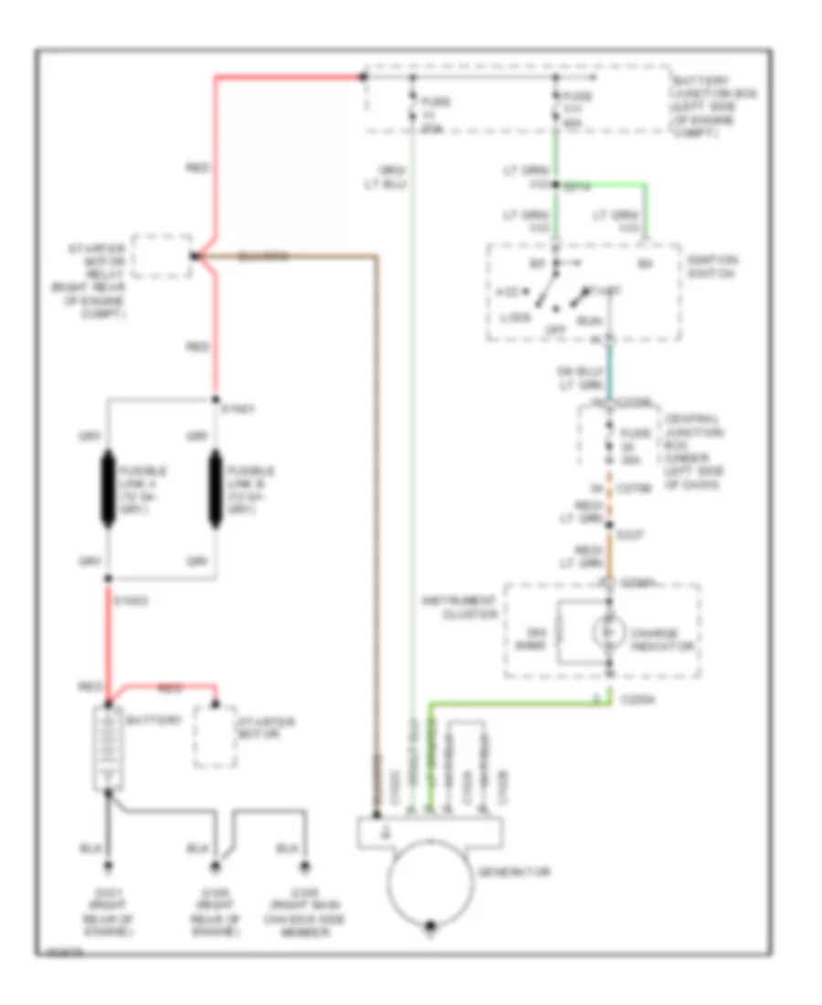 https://portal-diagnostov.com/license.html
Automotive Electricians Portal FZCO
Automotive Electricians Portal FZCO
https://portal-diagnostov.com/license.html
https://portal-diagnostov.com/license.html
Automotive Electricians Portal FZCO
Automotive Electricians Portal FZCOList of elements for Charging Wiring Diagram for Ford Pickup F150 2002:
- 0hms
- Acc
- Battery
- Battery junction box (left side of engine compt)
- C102a
- C102b
- C102c
- C220a
- C270b
- Central junction box (under left side of dash)
- Charge indicator
- Fuse 2oa
- Fuse 30a
- Fuse 40a
- G100 (right rear of engine)
- G101 (right rear of engine)
- G105 (right main chassis side member
- Generator
- Ignition switch
- Instrument cluster
- Lock
- Off
- Red
- Run
- S1001
- S1002
- S237
- Start
- Starter motor
- Starter motor relay (right rear of engine compt)
Starting Wiring Diagram for Ford Pickup F150 2002
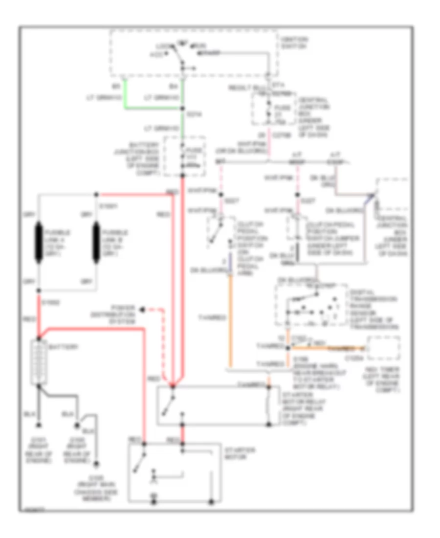 https://portal-diagnostov.com/license.html
Automotive Electricians Portal FZCO
Automotive Electricians Portal FZCO
https://portal-diagnostov.com/license.html
https://portal-diagnostov.com/license.html
Automotive Electricians Portal FZCO
Automotive Electricians Portal FZCOList of elements for Starting Wiring Diagram for Ford Pickup F150 2002:
- A/t esof
- A/t msof
- Acc
- Battery
- Battery junction box (left side of engine compt)
- C1254
- C167
- C270b
- Central junction box (under left side of dash)
- Clutch pedal position switch (on clutch pedal arm)
- Clutch pedal position switch jumper (under left side of dash)
- Digital transmission range sensor (left side of transmission)
- Fuse 15a
- Fuse 40a
- G100 (right rear of engine)
- G101 (right rear of engine)
- G105 (right main chassis side member)
- Ignition switch
- Lock
- M/t
- Ngv
- Ngv timer (left rear of engine compt)
- Off
- Power distribution system
- Red
- Run
- S1001
- S1002
- S198 (engine harn, near breakout to starter motor relay)
- S214
- S227
- Sta
- Start
- Starter motor
- Starter motor relay (right rear of engine compt)
- Tan/red
SUPPLEMENTAL RESTRAINTS
Supplemental Restraint Wiring Diagram for Ford Pickup F150 2002
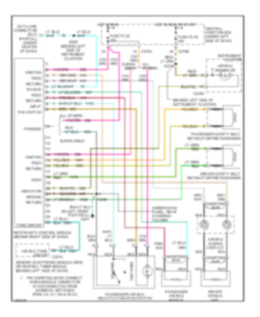 https://portal-diagnostov.com/license.html
Automotive Electricians Portal FZCO
Automotive Electricians Portal FZCO
https://portal-diagnostov.com/license.html
https://portal-diagnostov.com/license.html
Automotive Electricians Portal FZCO
Automotive Electricians Portal FZCOList of elements for Supplemental Restraint Wiring Diagram for Ford Pickup F150 2002:
- (behind left side of instrument cluster)
- (in left front footwell) g201
- (partial) (under center of dash)
- (under dash panel, near steering column)
- 1000 ohms
- 500 ohms
- Air bag indicator
- Air bag sliding contact
- Air bag tone driver
- All others
- C201a
- C220a
- C270a
- C270b
- Central junction box (under left side of dash)
- Data link connector (dlc)
- Driver air bag unit
- Driver safety belt retractor pretensioner
- Feed
- Fuse f2.22 10a
- Fuse f2.30 30a
- Generic electronic module (gem) or central timer module (behind left side of dash)
- Ground
- Hot in run
- Hot in run or start
- Ignition
- Indicator
- Input
- Instrument cluster
- Iso bus
- Nca
- Pad switch
- Passenger air bag deactivation (pad) switch
- Passenger air bag module
- Passenger safety belt retractor pretensioner
- Pin shorting bars connect when module connector is disconnected from harness, between (pins 3-4, 6-7, 8-9 & 20-21)
- Pwr/gnd
- Restraints control module (behind right side of dash)
- Return
- S208
- S229 (behind left side of instrument cluster)
- S237
- Shorting bar
- Super crew
- Tone driver
TRANSMISSION
4.2L
4.2L, A/T Wiring Diagram, 4R70W for Ford Pickup F150 2002
 https://portal-diagnostov.com/license.html
Automotive Electricians Portal FZCO
Automotive Electricians Portal FZCO
https://portal-diagnostov.com/license.html
https://portal-diagnostov.com/license.html
Automotive Electricians Portal FZCO
Automotive Electricians Portal FZCOList of elements for 4.2L, A/T Wiring Diagram, 4R70W for Ford Pickup F150 2002:
- (left rear of engine compt)
- (rear of engine compt)
- (right rear of engine compt)
- (right rear of engine compt) g101
- (under center of dash) data link connector
- 4.2l
- 4.6/5.4l
- 4r70w transmission
- 4wd circuit
- 4wd low
- Abs control module
- Anti-lock brakes system
- Autolamp module, anti-theft & warning systems
- Battery junction box (left side of engine compt)
- Bpp sw
- Brake pedal position switch (under left side of dash)
- C175
- C270b
- Central junction box (under left side of dash)
- Cht
- Cylinder head temperature (cht) sensor (4.2l: rear of left cyl head) (4.6l/5.4l: top front of engine)
- Data
- Digital transmission range sensor (left side of transmission)
- Dlc (+)
- Dlc (-)
- Electronic pressure control solenoid
- Engine controls system
- Epc
- Exterior lights module
- Fuse 15a
- Fuse 30a
- Fuse 5a
- G104 (left front of engine compt)
- Hot at all times
- Hot in run or start
- Iat
- Ignition coils, radio noise capacitor
- Instrument cluster system
- Instrument cluster, anti- theft system
- Intake air temperature sensor (on intake manifold)
- Nca
- Oss
- Output shaft speed sensor (left side of trans)
- Pc 1
- Pc 2
- Pcm power diode
- Pcm power relay
- Pnk
- Powertrain control module (pcm) (right side of engine compt)
- Pressure controller 1
- Pressure controller 2
- Pwr gnd
- R p
- Red
- S100
- S1003 (left rear of engine compt)
- S106
- S116
- S127 (left rear of engine compt)
- S135
- S136
- S137
- S138
- S140
- S141
- S155 (left rear of engine compt)
- S160 (left rear of engine compt)
- S225
- S237
- S274
- S297 (behind left side of dash)
- Sig rtn
- Tcc
- Tcil
- Tcs
- Tcss
- Tft
- Throttle position (tp) sensor (on throttle body)
- Torque converter clutch (tcc) solenoid
- Tr1
- Tr2
- Tr3
- Tr4
- Transfer case speed sensor (left rear of trans)
- Transmission control switch (tcs) (end of transmission selector lever)
- Transmission fluid temperature sensor
- Vpwr
- Vref
4WD Wiring Diagram, Electronic for Ford Pickup F150 2002
 https://portal-diagnostov.com/license.html
Automotive Electricians Portal FZCO
Automotive Electricians Portal FZCO
https://portal-diagnostov.com/license.html
https://portal-diagnostov.com/license.html
Automotive Electricians Portal FZCO
Automotive Electricians Portal FZCOList of elements for 4WD Wiring Diagram, Electronic for Ford Pickup F150 2002:
- (behind left side of dash)
- (left side of vehicle underbody) s142
- (right side of engine compt) 4x2 center axle disconnect solenoid
- (right side of engine compt) 4x4 center axle disconnect solenoid
- (under left side of dash) central junction box
- 1.1k ohms
- 3.9k ohms
- 4wd high ind
- 4wd low ind
- 4wd low out
- 4wd output
- 4x2 sol
- 4x4 high ind
- 4x4 mode sw
- 4x4 sol
- Abs control module
- Auxiliary relay box 3 (behind right center of dash)
- Batt
- Battery junction box (left side of engine compt)
- Bpp sw input
- Brake pedal position switch (under left side of dash)
- Brake pressure switch
- Brake shift interlock
- C175
- C201a
- C201c
- C201d
- C220a
- C220b
- C270a
- C270b
- Central junction box (under left side of dash)
- Computer data lines system
- Digital transmission range (dtr) sensor (left side of transmission)
- Exterior lights system
- Flasher relay, overhead console
- Four-wheel drive switch
- Fuse 10a
- Fuse 30a
- Fuse 5a
- G102 (right rear of engine compt)
- G200 (at right front footwell)
- G201 (at left front footwell)
- Gem module
- Generic electronic module (gem) (behind left side of dash)
- H2l
- H2l rly ctrl
- Hot at all times
- Hot in run
- Illumination
- Instrument cluster
- Interior lights (instrument illumination)
- L2h
- L2h rly ctrl
- Magnetic clutch
- Neutral sw in
- Off
- Ohms
- Powertrain control module (right side of engine compt)
- Red
- S102
- S120
- S201
- S202
- S207
- S213
- S228
- S232
- S238 (under dash, near steering column)
- S265
- S274
- S297
- Shift motor
- Sig return
- Sw a input
- Sw b input
- Sw c input
- Sw d input
- Tan/red
- Tcec rly ctrl
- Trailer tow battery charge relay
- Transfer case assembly (below vehicle, behind trans)
- Transfer case electric clutch relay
- Transfer case relay module (behind center of dash)
- Wiper/washer (multi-function switch)
4WD Wiring Diagram, Mechanical for Ford Pickup F150 2002
 https://portal-diagnostov.com/license.html
Automotive Electricians Portal FZCO
Automotive Electricians Portal FZCO
https://portal-diagnostov.com/license.html
https://portal-diagnostov.com/license.html
Automotive Electricians Portal FZCO
Automotive Electricians Portal FZCOList of elements for 4WD Wiring Diagram, Mechanical for Ford Pickup F150 2002:
- (right side of engine compt) 4x2 center axle disconnect solenoid
- (right side of engine compt) 4x4 center axle disconnect solenoid
- (right side of engine compt) powertrain control module
- 4wd hi ind
- 4wd high ind
- 4wd low ind
- 4x2
- 4x2 sol
- 4x4 high/ low indicator switch (left side of transmission)
- 4x4 lo in
- 4x4 sol
- 4x4 sw in
- Abs control module
- Auxiliary relay box 3 (behind right center of dash)
- Battery junction box (left side of engine compt)
- Brake shift interlock
- C175
- C201c
- C220a
- C220b
- C270a
- C270b
- Central junction box (under left side of dash)
- Computer data lines system
- Flasher relay, overhead console
- Fuse 10a
- Fuse 30a
- Fuse 5a
- Gem module
- Generic electronic module (gem) (behind left side of dash)
- Hot at all times
- Hot in run
- Instrument cluster
- Magnetic clutch
- Mechanical shift-on-the -fly relay
- Not used
- Red
- S120
- S142 (left side of vehicle underbody)
- S228
- S232 (behind left side of dash)
- S265
- Scp bus+
- Scp bus-
- Sotf relay
- Tan/red
- Trailer tow battery charge relay
- Transfer case assembly
4.6L
4.6L, A/T Wiring Diagram, 4R70W for Ford Pickup F150 2002
 https://portal-diagnostov.com/license.html
Automotive Electricians Portal FZCO
Automotive Electricians Portal FZCO
https://portal-diagnostov.com/license.html
https://portal-diagnostov.com/license.html
Automotive Electricians Portal FZCO
Automotive Electricians Portal FZCOList of elements for 4.6L, A/T Wiring Diagram, 4R70W for Ford Pickup F150 2002:
- (left rear of engine compt)
- (rear of engine compt)
- (right rear of engine compt)
- (right rear of engine compt) g101
- (under center of dash) data link connector
- 4.2l
- 4.6/5.4l
- 4r70w transmission
- 4wd circuit
- 4wd low
- Abs control module
- Anti-lock brakes system
- Autolamp module, anti-theft & warning systems
- Battery junction box (left side of engine compt)
- Bpp sw
- Brake pedal position switch (under left side of dash)
- C175
- C270b
- Central junction box (under left side of dash)
- Cht
- Cylinder head temperature (cht) sensor (4.2l: rear of left cyl head) (4.6l/5.4l: top front of engine)
- Data
- Digital transmission range sensor (left side of transmission)
- Dlc (+)
- Dlc (-)
- Electronic pressure control solenoid
- Engine controls system
- Epc
- Exterior lights module
- Fuse 15a
- Fuse 30a
- Fuse 5a
- G104 (left front of engine compt)
- Hot at all times
- Hot in run or start
- Iat
- Ignition coils, radio noise capacitor
- Instrument cluster system
- Instrument cluster, anti- theft system
- Intake air temperature sensor (on intake manifold)
- Nca
- Oss
- Output shaft speed sensor (left side of trans)
- Pc 1
- Pc 2
- Pcm power diode
- Pcm power relay
- Pnk
- Powertrain control module (pcm) (right side of engine compt)
- Pressure controller 1
- Pressure controller 2
- Pwr gnd
- R p
- Red
- S100
- S1003 (left rear of engine compt)
- S106
- S116
- S127 (left rear of engine compt)
- S135
- S136
- S137
- S138
- S140
- S141
- S155 (left rear of engine compt)
- S160 (left rear of engine compt)
- S225
- S237
- S274
- S297 (behind left side of dash)
- Sig rtn
- Tcc
- Tcil
- Tcs
- Tcss
- Tft
- Throttle position (tp) sensor (on throttle body)
- Torque converter clutch (tcc) solenoid
- Tr1
- Tr2
- Tr3
- Tr4
- Transfer case speed sensor (left rear of trans)
- Transmission control switch (tcs) (end of transmission selector lever)
- Transmission fluid temperature sensor
- Vpwr
- Vref
4WD Wiring Diagram, Electronic for Ford Pickup F150 2002
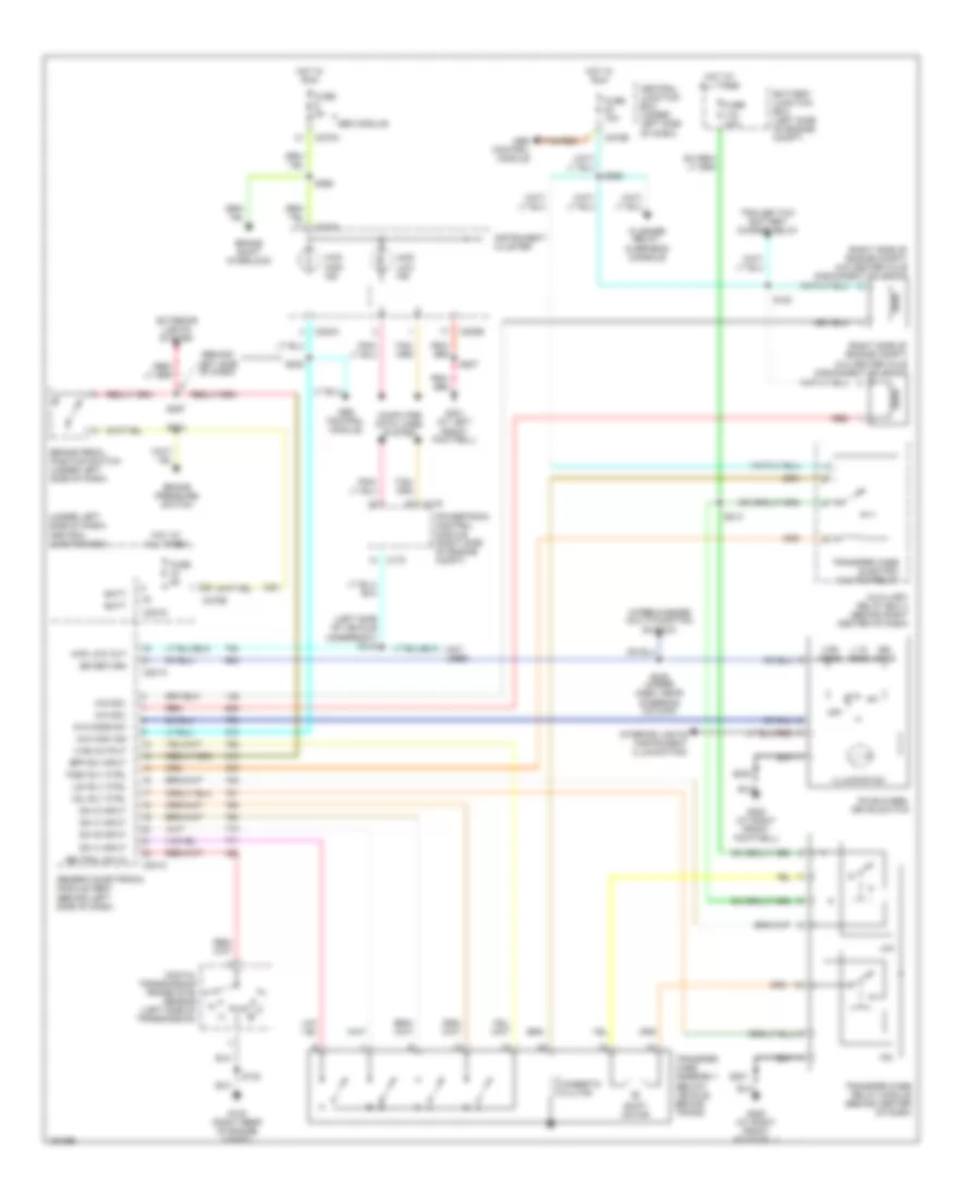 https://portal-diagnostov.com/license.html
Automotive Electricians Portal FZCO
Automotive Electricians Portal FZCO
https://portal-diagnostov.com/license.html
https://portal-diagnostov.com/license.html
Automotive Electricians Portal FZCO
Automotive Electricians Portal FZCOList of elements for 4WD Wiring Diagram, Electronic for Ford Pickup F150 2002:
- (behind left side of dash)
- (left side of vehicle underbody) s142
- (right side of engine compt) 4x2 center axle disconnect solenoid
- (right side of engine compt) 4x4 center axle disconnect solenoid
- (under left side of dash) central junction box
- 1.1k ohms
- 3.9k ohms
- 4wd high ind
- 4wd low ind
- 4wd low out
- 4wd output
- 4x2 sol
- 4x4 high ind
- 4x4 mode sw
- 4x4 sol
- Abs control module
- Auxiliary relay box 3 (behind right center of dash)
- Batt
- Battery junction box (left side of engine compt)
- Bpp sw input
- Brake pedal position switch (under left side of dash)
- Brake pressure switch
- Brake shift interlock
- C175
- C201a
- C201c
- C201d
- C220a
- C220b
- C270a
- C270b
- Central junction box (under left side of dash)
- Computer data lines system
- Digital transmission range (dtr) sensor (left side of transmission)
- Exterior lights system
- Flasher relay, overhead console
- Four-wheel drive switch
- Fuse 10a
- Fuse 30a
- Fuse 5a
- G102 (right rear of engine compt)
- G200 (at right front footwell)
- G201 (at left front footwell)
- Gem module
- Generic electronic module (gem) (behind left side of dash)
- H2l
- H2l rly ctrl
- Hot at all times
- Hot in run
- Illumination
- Instrument cluster
- Interior lights (instrument illumination)
- L2h
- L2h rly ctrl
- Magnetic clutch
- Neutral sw in
- Off
- Ohms
- Powertrain control module (right side of engine compt)
- Red
- S102
- S120
- S201
- S202
- S207
- S213
- S228
- S232
- S238 (under dash, near steering column)
- S265
- S274
- S297
- Shift motor
- Sig return
- Sw a input
- Sw b input
- Sw c input
- Sw d input
- Tan/red
- Tcec rly ctrl
- Trailer tow battery charge relay
- Transfer case assembly (below vehicle, behind trans)
- Transfer case electric clutch relay
- Transfer case relay module (behind center of dash)
- Wiper/washer (multi-function switch)
4WD Wiring Diagram, Mechanical for Ford Pickup F150 2002
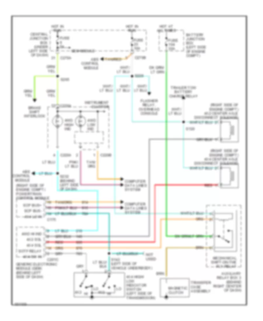 https://portal-diagnostov.com/license.html
Automotive Electricians Portal FZCO
Automotive Electricians Portal FZCO
https://portal-diagnostov.com/license.html
https://portal-diagnostov.com/license.html
Automotive Electricians Portal FZCO
Automotive Electricians Portal FZCOList of elements for 4WD Wiring Diagram, Mechanical for Ford Pickup F150 2002:
- (right side of engine compt) 4x2 center axle disconnect solenoid
- (right side of engine compt) 4x4 center axle disconnect solenoid
- (right side of engine compt) powertrain control module
- 4wd hi ind
- 4wd high ind
- 4wd low ind
- 4x2
- 4x2 sol
- 4x4 high/ low indicator switch (left side of transmission)
- 4x4 lo in
- 4x4 sol
- 4x4 sw in
- Abs control module
- Auxiliary relay box 3 (behind right center of dash)
- Battery junction box (left side of engine compt)
- Brake shift interlock
- C175
- C201c
- C220a
- C220b
- C270a
- C270b
- Central junction box (under left side of dash)
- Computer data lines system
- Flasher relay, overhead console
- Fuse 10a
- Fuse 30a
- Fuse 5a
- Gem module
- Generic electronic module (gem) (behind left side of dash)
- Hot at all times
- Hot in run
- Instrument cluster
- Magnetic clutch
- Mechanical shift-on-the -fly relay
- Not used
- Red
- S120
- S142 (left side of vehicle underbody)
- S228
- S232 (behind left side of dash)
- S265
- Scp bus+
- Scp bus-
- Sotf relay
- Tan/red
- Trailer tow battery charge relay
- Transfer case assembly
5.4L
4WD Wiring Diagram, Electronic for Ford Pickup F150 2002
 https://portal-diagnostov.com/license.html
Automotive Electricians Portal FZCO
Automotive Electricians Portal FZCO
https://portal-diagnostov.com/license.html
https://portal-diagnostov.com/license.html
Automotive Electricians Portal FZCO
Automotive Electricians Portal FZCOList of elements for 4WD Wiring Diagram, Electronic for Ford Pickup F150 2002:
- (behind left side of dash)
- (left side of vehicle underbody) s142
- (right side of engine compt) 4x2 center axle disconnect solenoid
- (right side of engine compt) 4x4 center axle disconnect solenoid
- (under left side of dash) central junction box
- 1.1k ohms
- 3.9k ohms
- 4wd high ind
- 4wd low ind
- 4wd low out
- 4wd output
- 4x2 sol
- 4x4 high ind
- 4x4 mode sw
- 4x4 sol
- Abs control module
- Auxiliary relay box 3 (behind right center of dash)
- Batt
- Battery junction box (left side of engine compt)
- Bpp sw input
- Brake pedal position switch (under left side of dash)
- Brake pressure switch
- Brake shift interlock
- C175
- C201a
- C201c
- C201d
- C220a
- C220b
- C270a
- C270b
- Central junction box (under left side of dash)
- Computer data lines system
- Digital transmission range (dtr) sensor (left side of transmission)
- Exterior lights system
- Flasher relay, overhead console
- Four-wheel drive switch
- Fuse 10a
- Fuse 30a
- Fuse 5a
- G102 (right rear of engine compt)
- G200 (at right front footwell)
- G201 (at left front footwell)
- Gem module
- Generic electronic module (gem) (behind left side of dash)
- H2l
- H2l rly ctrl
- Hot at all times
- Hot in run
- Illumination
- Instrument cluster
- Interior lights (instrument illumination)
- L2h
- L2h rly ctrl
- Magnetic clutch
- Neutral sw in
- Off
- Ohms
- Powertrain control module (right side of engine compt)
- Red
- S102
- S120
- S201
- S202
- S207
- S213
- S228
- S232
- S238 (under dash, near steering column)
- S265
- S274
- S297
- Shift motor
- Sig return
- Sw a input
- Sw b input
- Sw c input
- Sw d input
- Tan/red
- Tcec rly ctrl
- Trailer tow battery charge relay
- Transfer case assembly (below vehicle, behind trans)
- Transfer case electric clutch relay
- Transfer case relay module (behind center of dash)
- Wiper/washer (multi-function switch)
4WD Wiring Diagram, Mechanical for Ford Pickup F150 2002
 https://portal-diagnostov.com/license.html
Automotive Electricians Portal FZCO
Automotive Electricians Portal FZCO
https://portal-diagnostov.com/license.html
https://portal-diagnostov.com/license.html
Automotive Electricians Portal FZCO
Automotive Electricians Portal FZCOList of elements for 4WD Wiring Diagram, Mechanical for Ford Pickup F150 2002:
- (right side of engine compt) 4x2 center axle disconnect solenoid
- (right side of engine compt) 4x4 center axle disconnect solenoid
- (right side of engine compt) powertrain control module
- 4wd hi ind
- 4wd high ind
- 4wd low ind
- 4x2
- 4x2 sol
- 4x4 high/ low indicator switch (left side of transmission)
- 4x4 lo in
- 4x4 sol
- 4x4 sw in
- Abs control module
- Auxiliary relay box 3 (behind right center of dash)
- Battery junction box (left side of engine compt)
- Brake shift interlock
- C175
- C201c
- C220a
- C220b
- C270a
- C270b
- Central junction box (under left side of dash)
- Computer data lines system
- Flasher relay, overhead console
- Fuse 10a
- Fuse 30a
- Fuse 5a
- Gem module
- Generic electronic module (gem) (behind left side of dash)
- Hot at all times
- Hot in run
- Instrument cluster
- Magnetic clutch
- Mechanical shift-on-the -fly relay
- Not used
- Red
- S120
- S142 (left side of vehicle underbody)
- S228
- S232 (behind left side of dash)
- S265
- Scp bus+
- Scp bus-
- Sotf relay
- Tan/red
- Trailer tow battery charge relay
- Transfer case assembly
5.4L Bi-Fuel, A/T Wiring Diagram, 4R100 for Ford Pickup F150 2002
 https://portal-diagnostov.com/license.html
Automotive Electricians Portal FZCO
Automotive Electricians Portal FZCO
https://portal-diagnostov.com/license.html
https://portal-diagnostov.com/license.html
Automotive Electricians Portal FZCO
Automotive Electricians Portal FZCOList of elements for 5.4L Bi-Fuel, A/T Wiring Diagram, 4R100 for Ford Pickup F150 2002:
- (left rear of engine compt)
- (rear of engine compt)
- (right rear of engine compt)
- (right rear of engine compt) g101
- (right side of engine compt) powertrain control module (pcm)
- (under
- 4r100 transmission
- 4wd circuit
- 4wd low
- Abs control module
- Anti-lock brakes system
- Autolamp module, anti-theft & warning systems
- Battery junction box (left side of engine compt)
- Bpp sw
- Brake pedal position switch (under left side of dash)
- C175
- C270b
- Ccs
- Center of dash) data link connector
- Central junction box (under left side of dash)
- Cht
- Coast clutch control
- Cylinder head temperature (cht) sensor (top front of engine)
- Data
- Digital transmission range sensor (left side of transmission)
- Dlc (+)
- Dlc (-)
- Electronic pressure control solenoid
- Engine controls
- Engine controls system
- Epc
- Exterior lights module
- Fuse 15a
- Fuse 30a
- Fuse 5a
- G104 (left front of engine compt)
- Hot at all times
- Hot in run or start
- Iat
- Ignition coils, radio noise capacitor, ngv timer
- Instrument cluster system
- Instrument cluster, anti- theft system
- Intake air temperature sensor (on intake manifold)
- Nca
- Ngv module (front of engine)
- Oss
- Output shaft speed sensor (left side of trans)
- Pcm power diode
- Pcm power relay
- Pwr gnd
- R p
- Red
- S100
- S1003 (left rear of engine compt)
- S106
- S116
- S127
- S135
- S136
- S137 (excpt ngv)
- S138
- S140
- S141
- S155
- S156
- S157
- S160 (left rear of engine compt)
- S225
- S237
- S274
- S297 (behind left side of dash)
- Shift solenoid a
- Shift solenoid b
- Sig rtn
- Ss a
- Ss b
- Tcc
- Tcil
- Tcs
- Tft
- Throttle position (tp) sensor (on throttle body)
- Torque converter clutch solenoid
- Tr1
- Tr2
- Tr3
- Tr4
- Transmission control switch (tcs) (end of transmission selector lever)
- Transmission fluid temperature sensor
- Tss
- Turbine shaft speed sensor (left rear of trans)
- Vpwr
- Vref
5.4L CNG, A/T Wiring Diagram, 4R100 for Ford Pickup F150 2002
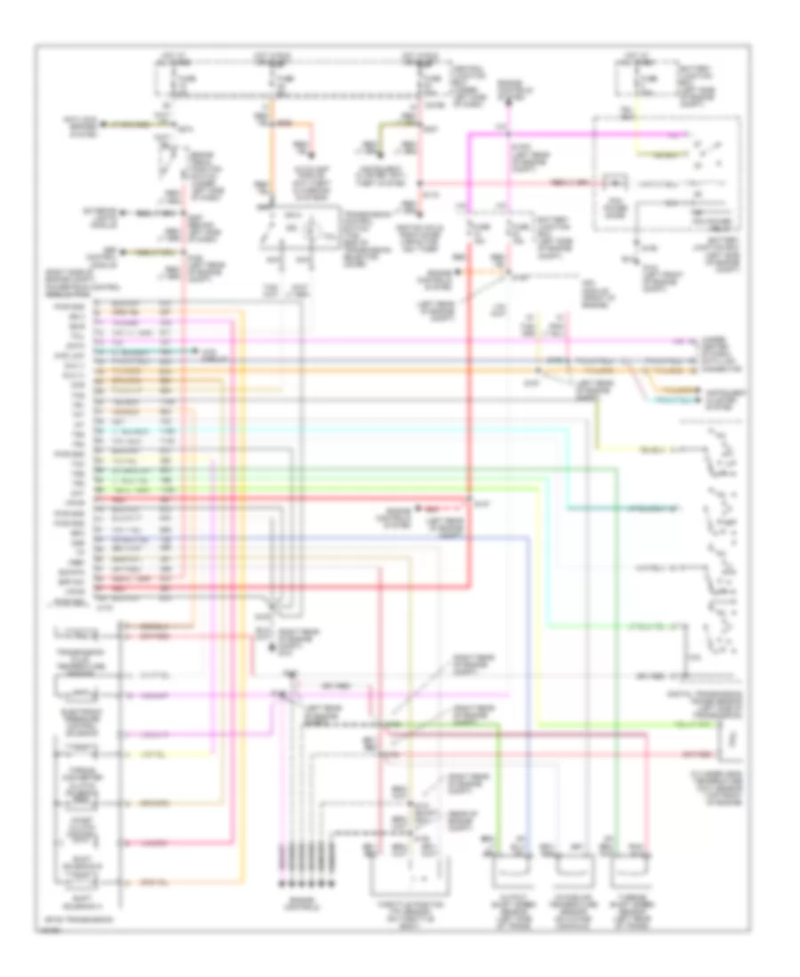 https://portal-diagnostov.com/license.html
Automotive Electricians Portal FZCO
Automotive Electricians Portal FZCO
https://portal-diagnostov.com/license.html
https://portal-diagnostov.com/license.html
Automotive Electricians Portal FZCO
Automotive Electricians Portal FZCOList of elements for 5.4L CNG, A/T Wiring Diagram, 4R100 for Ford Pickup F150 2002:
- (left rear of engine compt)
- (rear of engine compt)
- (right rear of engine compt)
- (right rear of engine compt) g101
- (right side of engine compt) powertrain control module (pcm)
- (under
- 4r100 transmission
- 4wd circuit
- 4wd low
- Abs control module
- Anti-lock brakes system
- Autolamp module, anti-theft & warning systems
- Battery junction box (left side of engine compt)
- Bpp sw
- Brake pedal position switch (under left side of dash)
- C175
- C270b
- Ccs
- Center of dash) data link connector
- Central junction box (under left side of dash)
- Cht
- Coast clutch control
- Cylinder head temperature (cht) sensor (top front of engine)
- Data
- Digital transmission range sensor (left side of transmission)
- Dlc (+)
- Dlc (-)
- Electronic pressure control solenoid
- Engine controls
- Engine controls system
- Epc
- Exterior lights module
- Fuse 15a
- Fuse 30a
- Fuse 5a
- G104 (left front of engine compt)
- Hot at all times
- Hot in run or start
- Iat
- Ignition coils, radio noise capacitor, ngv timer
- Instrument cluster system
- Instrument cluster, anti- theft system
- Intake air temperature sensor (on intake manifold)
- Nca
- Ngv module (front of engine)
- Oss
- Output shaft speed sensor (left side of trans)
- Pcm power diode
- Pcm power relay
- Pwr gnd
- R p
- Red
- S100
- S1003 (left rear of engine compt)
- S106
- S116
- S127
- S135
- S136
- S137 (excpt ngv)
- S138
- S140
- S141
- S155
- S156
- S157
- S160 (left rear of engine compt)
- S225
- S237
- S274
- S297 (behind left side of dash)
- Shift solenoid a
- Shift solenoid b
- Sig rtn
- Ss a
- Ss b
- Tcc
- Tcil
- Tcs
- Tft
- Throttle position (tp) sensor (on throttle body)
- Torque converter clutch solenoid
- Tr1
- Tr2
- Tr3
- Tr4
- Transmission control switch (tcs) (end of transmission selector lever)
- Transmission fluid temperature sensor
- Tss
- Turbine shaft speed sensor (left rear of trans)
- Vpwr
- Vref
5.4L Supercharged, A/T Wiring Diagram, 4R100 for Ford Pickup F150 2002
 https://portal-diagnostov.com/license.html
Automotive Electricians Portal FZCO
Automotive Electricians Portal FZCO
https://portal-diagnostov.com/license.html
https://portal-diagnostov.com/license.html
Automotive Electricians Portal FZCO
Automotive Electricians Portal FZCOList of elements for 5.4L Supercharged, A/T Wiring Diagram, 4R100 for Ford Pickup F150 2002:
- (left rear of engine compt)
- (rear of engine compt)
- (right rear of engine compt)
- (right rear of engine compt) g101
- (right side of engine compt) powertrain control module (pcm)
- (under
- 4r100 transmission
- 4wd circuit
- 4wd low
- Abs control module
- Anti-lock brakes system
- Autolamp module, anti-theft & warning systems
- Battery junction box (left side of engine compt)
- Bpp sw
- Brake pedal position switch (under left side of dash)
- C175
- C270b
- Ccs
- Center of dash) data link connector
- Central junction box (under left side of dash)
- Cht
- Coast clutch control
- Cylinder head temperature (cht) sensor (top front of engine)
- Data
- Digital transmission range sensor (left side of transmission)
- Dlc (+)
- Dlc (-)
- Electronic pressure control solenoid
- Engine controls
- Engine controls system
- Epc
- Exterior lights module
- Fuse 15a
- Fuse 30a
- Fuse 5a
- G104 (left front of engine compt)
- Hot at all times
- Hot in run or start
- Iat
- Ignition coils, radio noise capacitor, ngv timer
- Instrument cluster system
- Instrument cluster, anti- theft system
- Intake air temperature sensor (on intake manifold)
- Nca
- Ngv module (front of engine)
- Oss
- Output shaft speed sensor (left side of trans)
- Pcm power diode
- Pcm power relay
- Pwr gnd
- R p
- Red
- S100
- S1003 (left rear of engine compt)
- S106
- S116
- S127
- S135
- S136
- S137 (excpt ngv)
- S138
- S140
- S141
- S155
- S156
- S157
- S160 (left rear of engine compt)
- S225
- S237
- S274
- S297 (behind left side of dash)
- Shift solenoid a
- Shift solenoid b
- Sig rtn
- Ss a
- Ss b
- Tcc
- Tcil
- Tcs
- Tft
- Throttle position (tp) sensor (on throttle body)
- Torque converter clutch solenoid
- Tr1
- Tr2
- Tr3
- Tr4
- Transmission control switch (tcs) (end of transmission selector lever)
- Transmission fluid temperature sensor
- Tss
- Turbine shaft speed sensor (left rear of trans)
- Vpwr
- Vref
5.4L, A/T Wiring Diagram, 4R100 for Ford Pickup F150 2002
 https://portal-diagnostov.com/license.html
Automotive Electricians Portal FZCO
Automotive Electricians Portal FZCO
https://portal-diagnostov.com/license.html
https://portal-diagnostov.com/license.html
Automotive Electricians Portal FZCO
Automotive Electricians Portal FZCOList of elements for 5.4L, A/T Wiring Diagram, 4R100 for Ford Pickup F150 2002:
- (left rear of engine compt)
- (rear of engine compt)
- (right rear of engine compt)
- (right rear of engine compt) g101
- (right side of engine compt) powertrain control module (pcm)
- (under
- 4r100 transmission
- 4wd circuit
- 4wd low
- Abs control module
- Anti-lock brakes system
- Autolamp module, anti-theft & warning systems
- Battery junction box (left side of engine compt)
- Bpp sw
- Brake pedal position switch (under left side of dash)
- C175
- C270b
- Ccs
- Center of dash) data link connector
- Central junction box (under left side of dash)
- Cht
- Coast clutch control
- Cylinder head temperature (cht) sensor (top front of engine)
- Data
- Digital transmission range sensor (left side of transmission)
- Dlc (+)
- Dlc (-)
- Electronic pressure control solenoid
- Engine controls
- Engine controls system
- Epc
- Exterior lights module
- Fuse 15a
- Fuse 30a
- Fuse 5a
- G104 (left front of engine compt)
- Hot at all times
- Hot in run or start
- Iat
- Ignition coils, radio noise capacitor, ngv timer
- Instrument cluster system
- Instrument cluster, anti- theft system
- Intake air temperature sensor (on intake manifold)
- Nca
- Ngv module (front of engine)
- Oss
- Output shaft speed sensor (left side of trans)
- Pcm power diode
- Pcm power relay
- Pwr gnd
- R p
- Red
- S100
- S1003 (left rear of engine compt)
- S106
- S116
- S127
- S135
- S136
- S137 (excpt ngv)
- S138
- S140
- S141
- S155
- S156
- S157
- S160 (left rear of engine compt)
- S225
- S237
- S274
- S297 (behind left side of dash)
- Shift solenoid a
- Shift solenoid b
- Sig rtn
- Ss a
- Ss b
- Tcc
- Tcil
- Tcs
- Tft
- Throttle position (tp) sensor (on throttle body)
- Torque converter clutch solenoid
- Tr1
- Tr2
- Tr3
- Tr4
- Transmission control switch (tcs) (end of transmission selector lever)
- Transmission fluid temperature sensor
- Tss
- Turbine shaft speed sensor (left rear of trans)
- Vpwr
- Vref
5.4L, A/T Wiring Diagram, 4R70W for Ford Pickup F150 2002
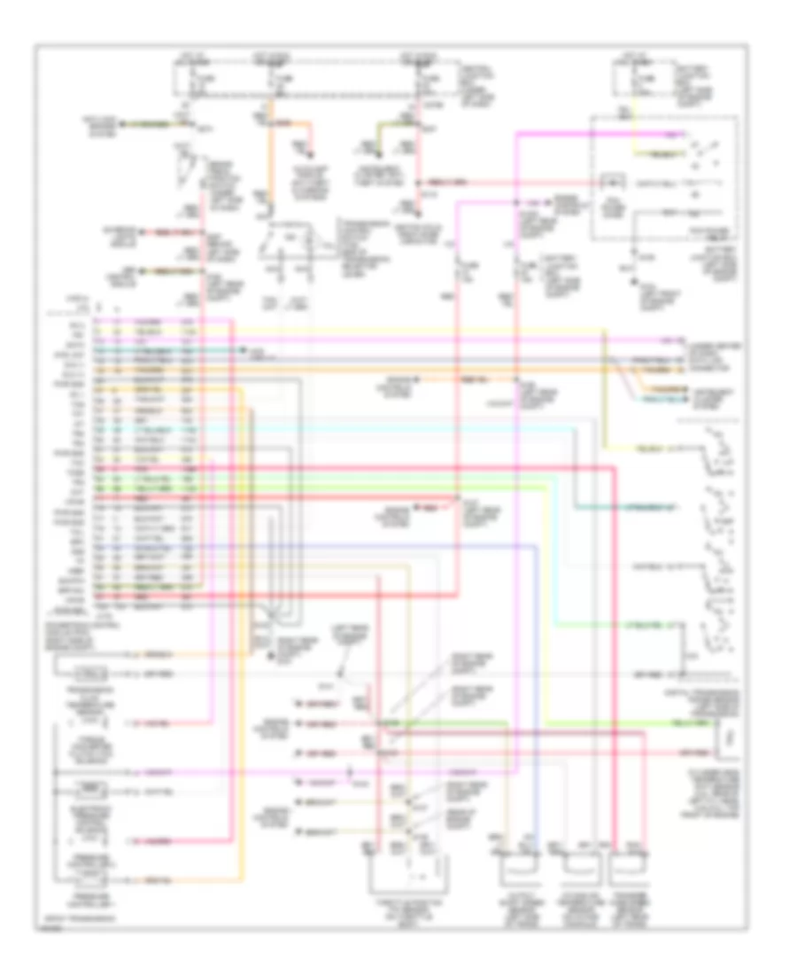 https://portal-diagnostov.com/license.html
Automotive Electricians Portal FZCO
Automotive Electricians Portal FZCO
https://portal-diagnostov.com/license.html
https://portal-diagnostov.com/license.html
Automotive Electricians Portal FZCO
Automotive Electricians Portal FZCOList of elements for 5.4L, A/T Wiring Diagram, 4R70W for Ford Pickup F150 2002:
- (left rear of engine compt)
- (rear of engine compt)
- (right rear of engine compt)
- (right rear of engine compt) g101
- (under center of dash) data link connector
- 4.2l
- 4.6/5.4l
- 4r70w transmission
- 4wd circuit
- 4wd low
- Abs control module
- Anti-lock brakes system
- Autolamp module, anti-theft & warning systems
- Battery junction box (left side of engine compt)
- Bpp sw
- Brake pedal position switch (under left side of dash)
- C175
- C270b
- Central junction box (under left side of dash)
- Cht
- Cylinder head temperature (cht) sensor (4.2l: rear of left cyl head) (4.6l/5.4l: top front of engine)
- Data
- Digital transmission range sensor (left side of transmission)
- Dlc (+)
- Dlc (-)
- Electronic pressure control solenoid
- Engine controls system
- Epc
- Exterior lights module
- Fuse 15a
- Fuse 30a
- Fuse 5a
- G104 (left front of engine compt)
- Hot at all times
- Hot in run or start
- Iat
- Ignition coils, radio noise capacitor
- Instrument cluster system
- Instrument cluster, anti- theft system
- Intake air temperature sensor (on intake manifold)
- Nca
- Oss
- Output shaft speed sensor (left side of trans)
- Pc 1
- Pc 2
- Pcm power diode
- Pcm power relay
- Pnk
- Powertrain control module (pcm) (right side of engine compt)
- Pressure controller 1
- Pressure controller 2
- Pwr gnd
- R p
- Red
- S100
- S1003 (left rear of engine compt)
- S106
- S116
- S127 (left rear of engine compt)
- S135
- S136
- S137
- S138
- S140
- S141
- S155 (left rear of engine compt)
- S160 (left rear of engine compt)
- S225
- S237
- S274
- S297 (behind left side of dash)
- Sig rtn
- Tcc
- Tcil
- Tcs
- Tcss
- Tft
- Throttle position (tp) sensor (on throttle body)
- Torque converter clutch (tcc) solenoid
- Tr1
- Tr2
- Tr3
- Tr4
- Transfer case speed sensor (left rear of trans)
- Transmission control switch (tcs) (end of transmission selector lever)
- Transmission fluid temperature sensor
- Vpwr
- Vref
WARNING SYSTEMS
Warning System Wiring Diagrams for Ford Pickup F150 2002
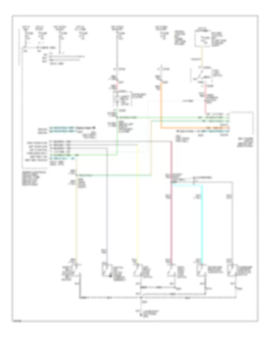 https://portal-diagnostov.com/license.html
Automotive Electricians Portal FZCO
Automotive Electricians Portal FZCO
https://portal-diagnostov.com/license.html
https://portal-diagnostov.com/license.html
Automotive Electricians Portal FZCO
Automotive Electricians Portal FZCOList of elements for Warning System Wiring Diagrams for Ford Pickup F150 2002:
- (gem)
- (gem) (ctm)
- (lower right kick panel) g200
- (w/ supercrew)
- Bat
- Battery junction box (in left side of engine compt)
- Belt minder module (behind left side of dash)
- C201a c2224
- C201d
- C2031a
- C2031b
- C205b
- C220a
- C220b
- C270b
- Central junction box (under left side of dash)
- Driver side rear door ajar switch
- Fuse 15a
- Fuse 30a
- Fuse 5a
- G201 (left front footwell)
- Generic electronic module (gem)/ central timer module (ctm) (behind left side of dash)
- Ground
- Head
- Hot at all times
- Hot in run
- Hot in run or acc
- Hot in run or start
- Hot in start
- Ign
- Ignition key switch (inside steering assembly)
- Instrument cluster
- Key in ignition
- Left door ajar
- Left front door ajar switch
- Main light switch
- Nca
- Off
- Park
- Park/head input
- Passenger side rear door ajar switch
- Right door ajar
- Right front door ajar switch
- S205
- S208
- S225
- S237
- S304
- S501
- S600
- S774
- S864
- Safety belt switch (in seat belt buckle)
- Safety belts indi- cator
- Seat belt buckle
- Seat belt ind
WIPER/WASHER
Wiper/Washer Wiring Diagram for Ford Pickup F150 2002
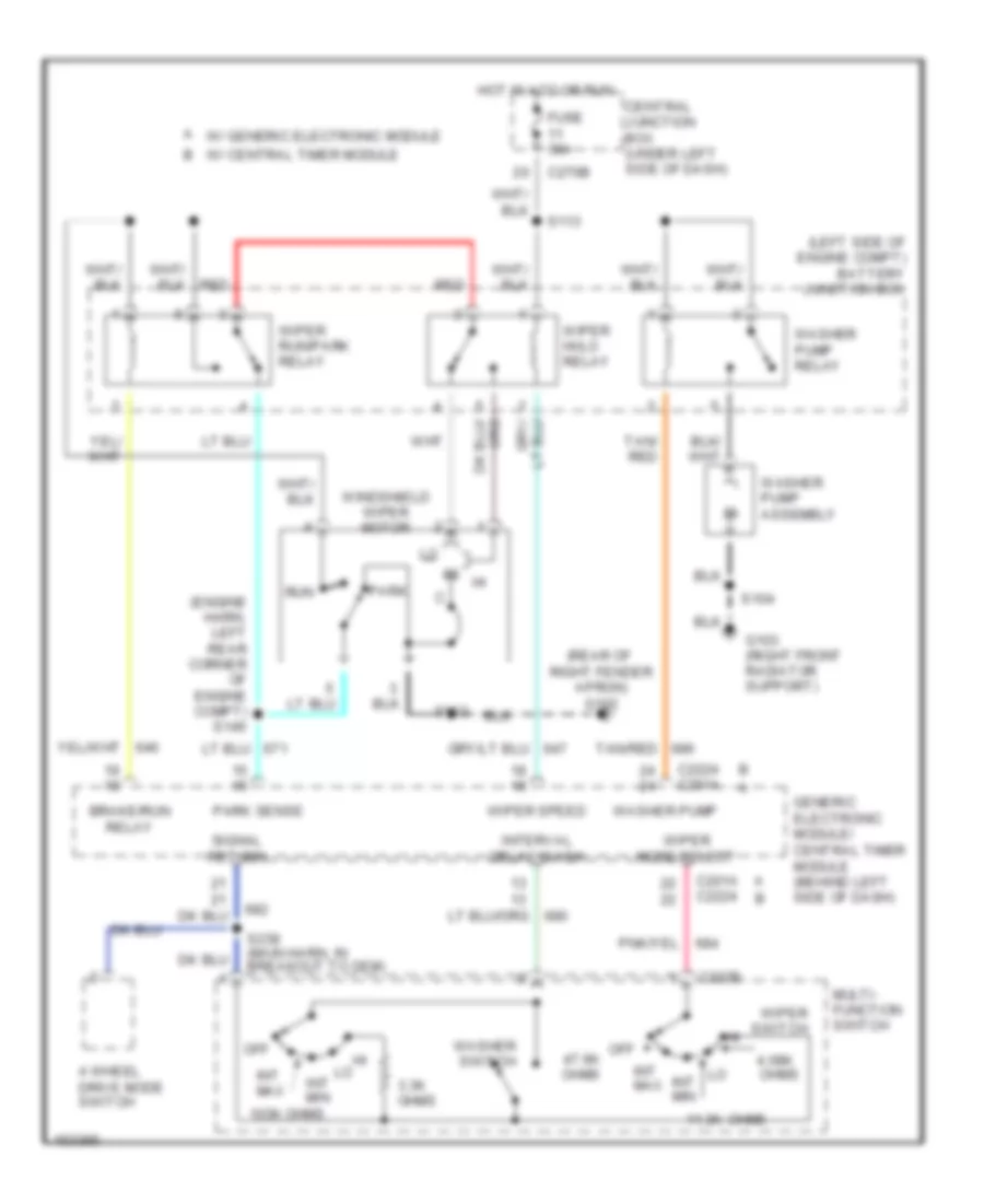 https://portal-diagnostov.com/license.html
Automotive Electricians Portal FZCO
Automotive Electricians Portal FZCO
https://portal-diagnostov.com/license.html
https://portal-diagnostov.com/license.html
Automotive Electricians Portal FZCO
Automotive Electricians Portal FZCOList of elements for Wiper/Washer Wiring Diagram for Ford Pickup F150 2002:
- (engine harn, left rear corner of engine compt) s146
- (left side of engine compt) battery junction box
- (rear of right fender apron) g102
- 103k ohms
- 11.3k
- 3.3k ohms
- 4 wheel drive mode switch
- 4.08k
- Brake/run relay
- C201a c2224
- C202b
- C2224 c201a
- C270b
- Central junction box (under left side of dash)
- Fuse 30a
- G103 (right front radiator support)
- Generic electronic module/ central timer module (behind left side of dash)
- Hot in acc or run
- Int max
- Int min
- Interval delay/wash
- Multi- function switch
- Off
- Off 47.6k ohms
- Ohms
- Park
- Park sense
- Red
- Run
- S102
- S104
- S113
- S238 (main harn, in breakout to gem)
- Signal return
- Tan/ red
- Tan/red
- W/ central timer module
- W/ generic electronic module
- Washer pump
- Washer pump assembly
- Washer pump relay
- Washer switch
- Windshield wiper motor
- Wiper hi/lo relay
- Wiper mode select
- Wiper run/park relay
- Wiper speed
- Wiper switch

 Čeština
 Dansk
Dansk Deutsch
 Ελληνικά
 English
 English
 Español
 Suomi
Suomi Français
 Français
 עברית
עברית Hrvatski
 Magyar
 Italiano
 한국어
한국어 Nederlands
 Polski
 Português
 Português
 Română
 Русский
 Slovenčina
 Slovenščina
 Svenska
 Türkçe
 中文 (中国)
