ANTI-THEFT
Anti-theft Wiring Diagram for Ford Probe GT 1993
 https://portal-diagnostov.com/license.html
Automotive Electricians Portal FZCO
Automotive Electricians Portal FZCO
https://portal-diagnostov.com/license.html
https://portal-diagnostov.com/license.html
Automotive Electricians Portal FZCO
Automotive Electricians Portal FZCO
List of elements for Anti-theft Wiring Diagram for Ford Probe GT 1993:
- 15a
- Acc
- Anti-theft control unit (behind left side of i/p, on central processing unit)
- Anti-theft indicator
- Armed signal
- Arming out
- Battery
- C2000
- C201
- C204
- C213
- C214
- C215
- C240
- C409
- Central processing unit (behind left side of i/p, rear of interior panel)
- Disarm input
- Engine fuse
- Exterior lights system (hazard lights)
- G106 (left front of vehicle, near fog light)
- G300 (below left front seat)
- G407 (lower center rear of luggage compartment)
- Ground
- Hazard lights
- Headlights
- Headlights system (headlight relay)
- Hood open
- Hood switch
- Hood switch (on engine compt latch assy)
- Horn
- Horn enable
- Horns system (horn relay)
- Hot at all times
- Hot in run or start
- Ignition
- Ignition switch
- Instrument cluster
- Interior fuse panel
- Joint connector
- Keyless entry module (in front of right quarter panel, behind quarter trim)
- Left door key cylinder switch (part of key cyl)
- Left door lk sw
- Left door lock switch (part of key cyl)
- Liftgate key cyl
- Liftgate key switch (right rear of luggage compt)
- Liftgate open
- Luggage compart- ment light switch (center of luggage compt)
- Meter fuse
- Nca
- Off
- Option #1
- Option #2
- Option sw
- Red
- Right door key cylinder switch (part of key cyl)
- Right door lk sw
- Right door lock switch (part of key cyl)
- Room fuse
- Run
- Start
- Start enable
- Starter interrupt relay
- Starting/ charging system (starter motor)
- With remote keyless entry
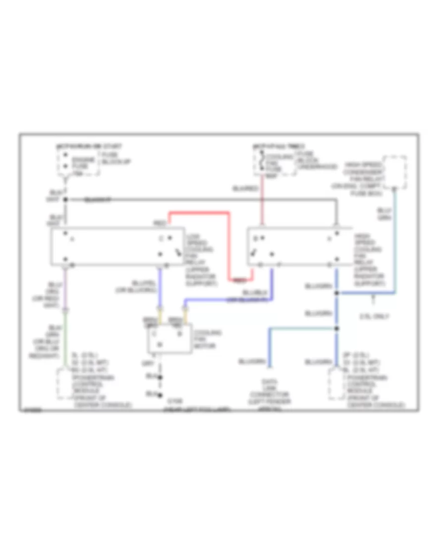
COOLING FAN
Cooling Fan Wiring Diagram for Ford Probe GT 1993
 https://portal-diagnostov.com/license.html
Automotive Electricians Portal FZCO
Automotive Electricians Portal FZCO
https://portal-diagnostov.com/license.html
https://portal-diagnostov.com/license.html
Automotive Electricians Portal FZCO
Automotive Electricians Portal FZCOList of elements for Cooling Fan Wiring Diagram for Ford Probe GT 1993:
- (2.5l) (2.0l m/t) (2.0l a/t)
- (near left fog lamp)
- 2.5l only
- 2p 3l
- 3l 3g
- Cooling fan fuse 40a
- Cooling fan motor
- Data link connector (left fender apron)
- Engine fuse 15a
- Fuse block: underhood
- Fuse block:i/p
- G108
- High speed condenser fan relay (on eng. compt. fuse box)
- High speed cooling fan relay (upper radiator support)
- Hot at all times
- Hot in run or start
- Low speed cooling fan relay (upper radiator support)
- Powertrain control module (front of center console)
- Red
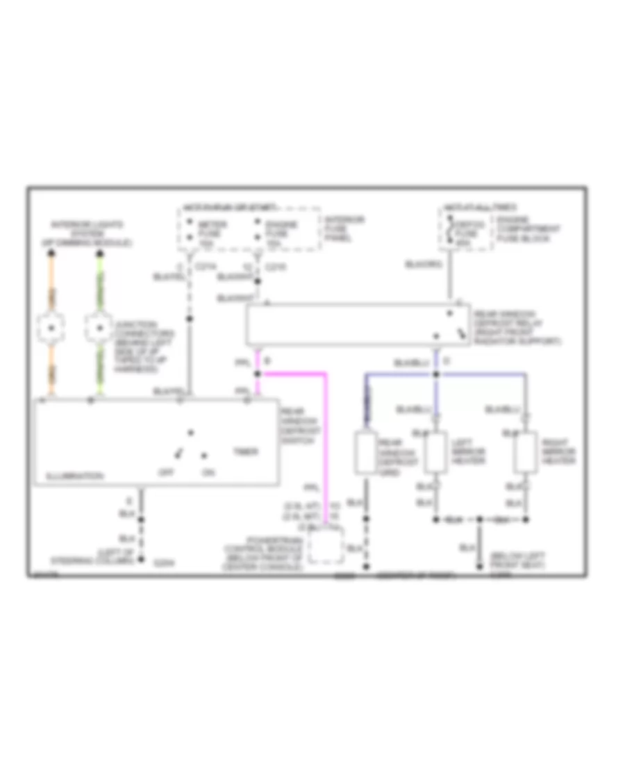
DEFOGGERS
Defogger Wiring Diagram for Ford Probe GT 1993
 https://portal-diagnostov.com/license.html
Automotive Electricians Portal FZCO
Automotive Electricians Portal FZCO
https://portal-diagnostov.com/license.html
https://portal-diagnostov.com/license.html
Automotive Electricians Portal FZCO
Automotive Electricians Portal FZCOList of elements for Defogger Wiring Diagram for Ford Probe GT 1993:
- (below left front seat) g300
- (center of roof)
- (left of steering column)
- 1o (2.0l a/t) (2.0l m/t) (2.5l)
- C214
- C215
- Defog fuse 40a
- Engine compartment fuse block
- Engine fuse 15a
- G204
- G909
- Hot at all times
- Hot in run or start
- Illumination
- Interior fuse panel
- Interior lights system (i/p dimming module)
- Junction connectors (behind left side of i/p taped to i/p harness)
- Left mirror heater
- Meter fuse 10a
- Off
- Powertrain control module (below front of center console)
- Rear window defrost grid
- Rear window defrost relay (right front radiator support)
- Rear window defrost switch
- Right mirror heater
- Timer
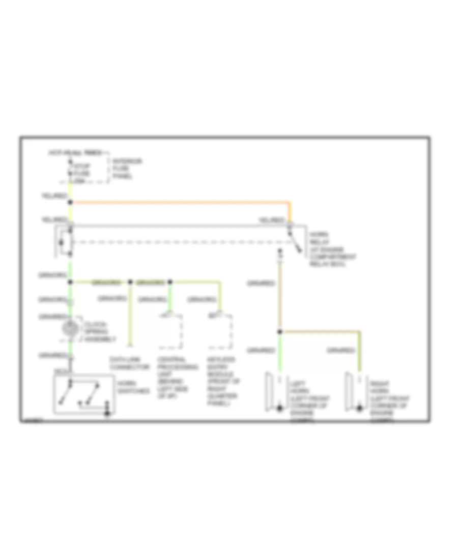
HORN
Horn Wiring Diagram for Ford Probe GT 1993
 https://portal-diagnostov.com/license.html
Automotive Electricians Portal FZCO
Automotive Electricians Portal FZCO
https://portal-diagnostov.com/license.html
https://portal-diagnostov.com/license.html
Automotive Electricians Portal FZCO
Automotive Electricians Portal FZCOList of elements for Horn Wiring Diagram for Ford Probe GT 1993:
-
-
- Central processing unit (behind left side of i/p)
- Clock- spring assembly
- Data link connector
- Horn relay (at engine compartment relay box)
- Horn switches
- Hot at all times
- Interior fuse panel
- Keyless entry module (front of right quarter panel)
- Left horn (left front corner of engine compt)
- Nca
- Right horn (left front corner of engine compt)
- Stop fuse 20a
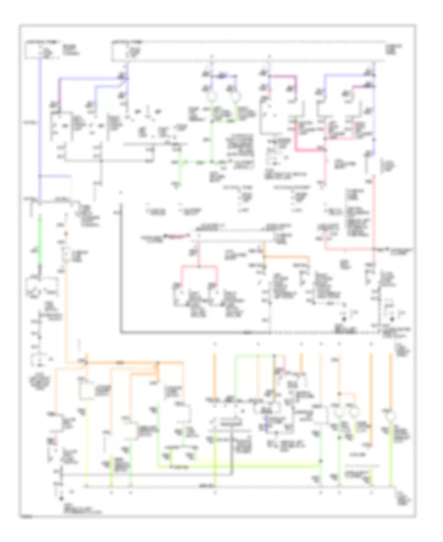
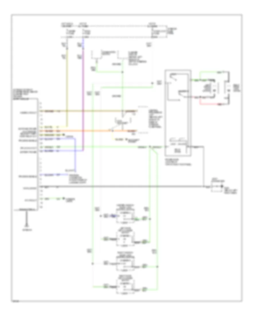
INTERIOR LIGHTS
Interior Light Wiring Diagram for Ford Probe GT 1993
 https://portal-diagnostov.com/license.html
Automotive Electricians Portal FZCO
Automotive Electricians Portal FZCO
https://portal-diagnostov.com/license.html
https://portal-diagnostov.com/license.html
Automotive Electricians Portal FZCO
Automotive Electricians Portal FZCOList of elements for Interior Light Wiring Diagram for Ford Probe GT 1993:
- (5 bulbs)
- (behind left center of i/p) g206
- (in front of right quarter panel, behind quarter trim) keyless entry module
- (lower center rear of lugg. compt)
- A/c- heater control assembly illum.
- Bat c
- C204
- Central processing unit (behind left side of i/p, on rear of interior fuse panel)
- Cigar lighter illum.
- Combination switch
- Courtesy f
- Courtesy lp switch in
- Courtesy lps out
- Dome lamp
- Dome/ map lamp assembly
- Door handle switch in
- Drl
- Engine compt fuse box
- G100 (left front of vehicle, near fog lamp)
- G204 (behind i/p, left of steering column)
- G300 (below left front seat)
- Glove box lamp
- Glove box lamp switch
- Graphic equalizer
- Ground
- Head
- Headlamp retractor switch
- Hot at all times
- Hot in run or start
- I/p dimming module (left side of dash)
- Ign a
- Instrument cluster
- Interior fuse panel
- J/c
- J/c (left side of dash)
- Key cyl g
- Left door courtesy lamp switch (on left b pillar)
- Left map lamp
- Left outside door handle switch (top rear of left door)
- Left vanity mirror lamp
- Liftgate washer switch
- Liftgate wiper switch
- Lps out
- Lugg compt lp switch in
- Lugg. compt lamp
- Lugg. compt lamp switch
- Main lamp switch
- Meter fuse 15a
- Module d
- Nca
- Nca ignition key cylinder lamp
- Nca left door key cylinder lamp
- Nca right door key cylinder lamp
- Off
- Oscillator
- Overdrive off switch
- Park
- Park lamp relay (in engine compt fuse box)
- Pnk
- Rear window defrost switch
- Red
- Right door courtesy lamp switch (on right b pillar)
- Right map lamp
- Right outside door handle switch (top rear of right door)
- Right vanity mirror lamp
- Room fuse 15a
- Solid state
- Tail fuse 15a
- W/o drl
- With anti- theft
- With illuminated entry
- With keyless entry
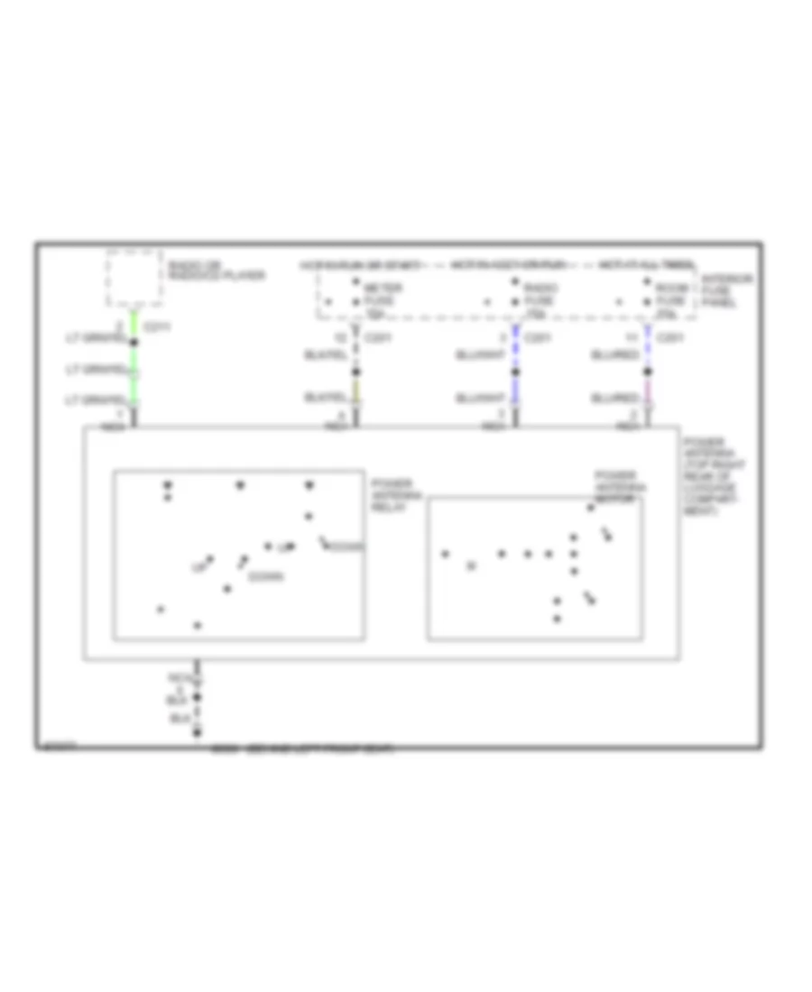
POWER ANTENNA
Power Antenna Wiring Diagram for Ford Probe GT 1993
 https://portal-diagnostov.com/license.html
Automotive Electricians Portal FZCO
Automotive Electricians Portal FZCO
https://portal-diagnostov.com/license.html
https://portal-diagnostov.com/license.html
Automotive Electricians Portal FZCO
Automotive Electricians Portal FZCOList of elements for Power Antenna Wiring Diagram for Ford Probe GT 1993:
- (behind left front seat)
- C201
- C211
- Down
- G300
- Hot at all times
- Hot in accy or run
- Hot in run or start
- Interior fuse panel
- Meter fuse 15a
- Nca
- Power antenna (top right rear of luggage compart- ment)
- Power antenna motor
- Power antenna relay
- Radio fuse 15a
- Radio or radio/cd player
- Room fuse 15a
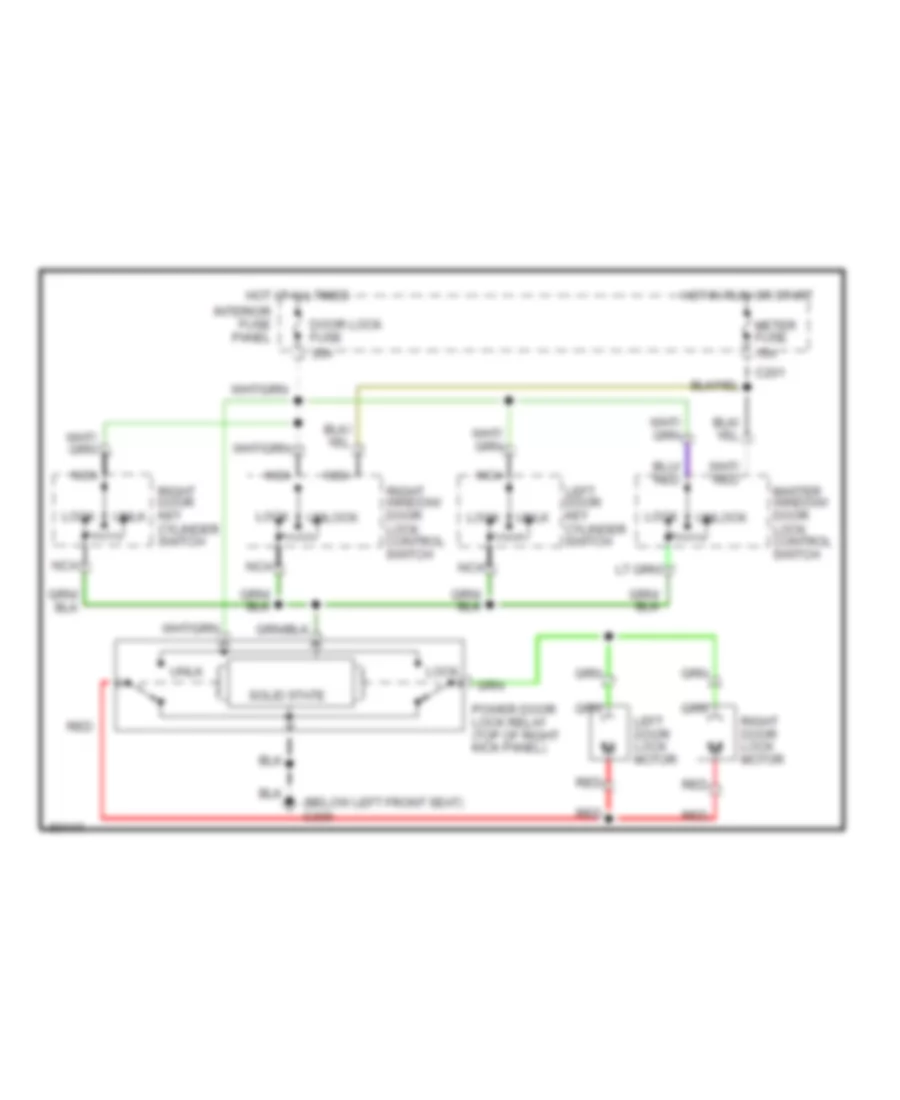
POWER DOOR LOCKS
Door Lock Wiring Diagram for Ford Probe GT 1993
 https://portal-diagnostov.com/license.html
Automotive Electricians Portal FZCO
Automotive Electricians Portal FZCO
https://portal-diagnostov.com/license.html
https://portal-diagnostov.com/license.html
Automotive Electricians Portal FZCO
Automotive Electricians Portal FZCOList of elements for Door Lock Wiring Diagram for Ford Probe GT 1993:
- (below left front seat) g300
- 15a
- 30a
- C201
- Door lock fuse
- Hot at all times
- Hot in run or start
- Interior fuse panel
- Left door key cylinder switch
- Left door lock motor
- Lock
- Master window/ door lock control switch
- Meter fuse
- Nca
- Power door lock relay (top of right kick panel)
- Red
- Right door key cylinder switch
- Right door lock motor
- Right window/ door lock control switch
- Solid state
- Unlk
- Unlock
Keyless Entry Wiring Diagram for Ford Probe GT 1993
 https://portal-diagnostov.com/license.html
Automotive Electricians Portal FZCO
Automotive Electricians Portal FZCO
https://portal-diagnostov.com/license.html
https://portal-diagnostov.com/license.html
Automotive Electricians Portal FZCO
Automotive Electricians Portal FZCOList of elements for Keyless Entry Wiring Diagram for Ford Probe GT 1993:
- (behind left side of i/p, left of steering column)
- (behind left side of i/p, rear of interior fuse panel)
- (in front of right quarter panel, behind quarter trim) keyless entry module
- (top of right kick panel)
- 15a
- 30a
- Antenna
- Anti-theft system
- Battery power
- Central processing unit
- Combination switch
- Door lock fuse
- Dr lk/unlk out
- Flasher module
- G300 (below left front seat)
- Hazard lps out
- Horn relay out
- Horns
- Hot at all times
- Hot in run or start
- Int lps out
- Interior fuse panel
- Interior lamps
- Joint connector
- Left door key cylinder switch
- Left door lock motor
- Lock
- Master window/ door lock control switch
- Meter fuse
- Module gnd
- Nca
- Power door lock relay
- Program connector (in right rear of luggage compt)
- Program enable
- Red
- Right door key cylinder switch
- Right door lock motor
- Right window/ door lock control switch
- Room fuse
- Solid state
- Switched power
- Transmitter in
- Unlk drs/dis- able anti-theft
- Unlock
- With anti-theft
Power Door Lock Wiring Diagram for Ford Probe GT 1993
 https://portal-diagnostov.com/license.html
Automotive Electricians Portal FZCO
Automotive Electricians Portal FZCO
https://portal-diagnostov.com/license.html
https://portal-diagnostov.com/license.html
Automotive Electricians Portal FZCO
Automotive Electricians Portal FZCOList of elements for Power Door Lock Wiring Diagram for Ford Probe GT 1993:
- (below left front seat) g300
- 15a
- 30a
- C201
- Door lock fuse
- Hot at all times
- Hot in run or start
- Interior fuse panel
- Left door key cylinder switch
- Left door lock motor
- Lock
- Master window/ door lock control switch
- Meter fuse
- Nca
- Power door lock relay (top of right kick panel)
- Red
- Right door key cylinder switch
- Right door lock motor
- Right window/ door lock control switch
- Solid state
- Unlk
- Unlock
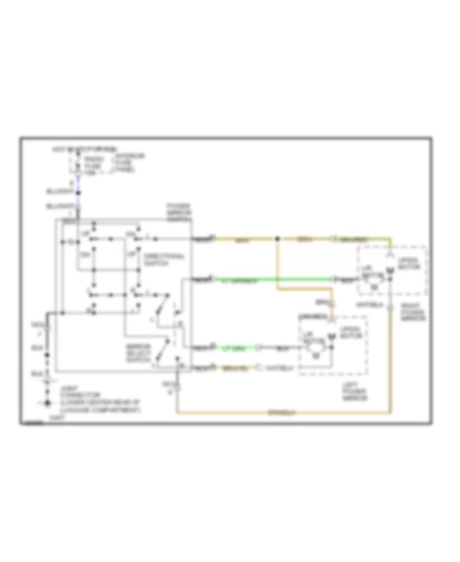
POWER MIRRORS
Power Mirror Wiring Diagram for Ford Probe GT 1993
 https://portal-diagnostov.com/license.html
Automotive Electricians Portal FZCO
Automotive Electricians Portal FZCO
https://portal-diagnostov.com/license.html
https://portal-diagnostov.com/license.html
Automotive Electricians Portal FZCO
Automotive Electricians Portal FZCOList of elements for Power Mirror Wiring Diagram for Ford Probe GT 1993:
- Directional switch
- G407
- Hot in accy or run
- I nca
- Interior fuse panel
- Joint connector (lower center rear of luggage compartment)
- L/r motor
- Left power mirror
- Mirror select switch
- Nca
- Power mirror switch
- Radio fuse 15a
- Right power mirror
- Up/dn motor
POWER SEATS
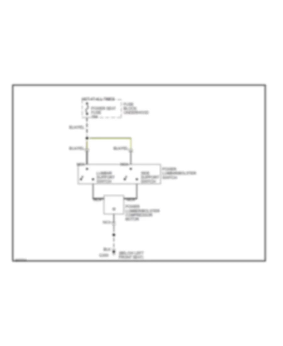
Lumbar Wiring Diagram for Ford Probe GT 1993
 https://portal-diagnostov.com/license.html
Automotive Electricians Portal FZCO
Automotive Electricians Portal FZCO
https://portal-diagnostov.com/license.html
https://portal-diagnostov.com/license.html
Automotive Electricians Portal FZCO
Automotive Electricians Portal FZCOList of elements for Lumbar Wiring Diagram for Ford Probe GT 1993:
- (below left front seat)
- Fuse block: underhood
- G300
- Hot at all times
- Lumbar support switch
- Nca
- Power lumbar/bolster switch
- Power lumber/bolster compressor motor
- Power seat fuse 30a
- Side support switch
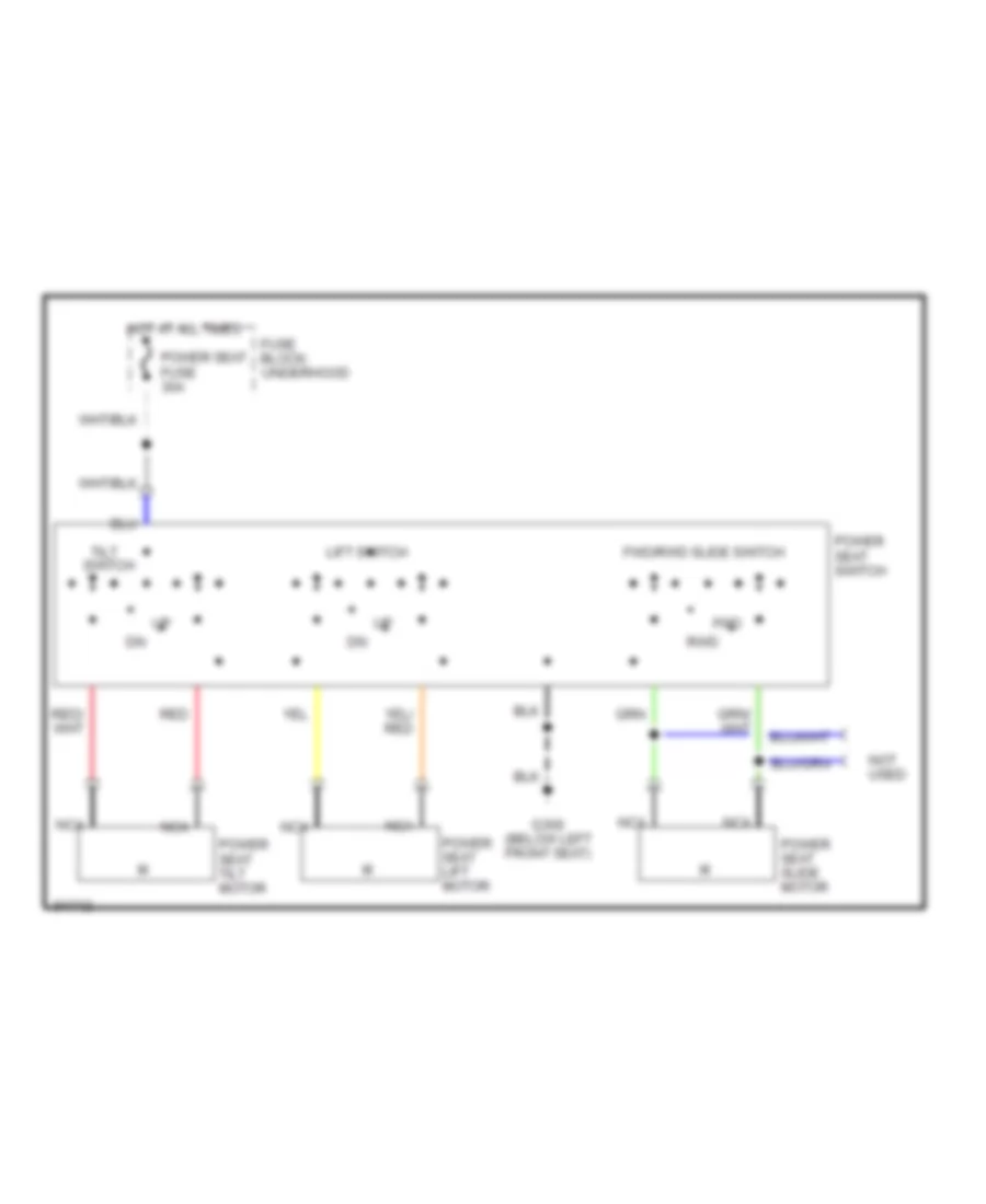
Power Seat Wiring Diagram for Ford Probe GT 1993
 https://portal-diagnostov.com/license.html
Automotive Electricians Portal FZCO
Automotive Electricians Portal FZCO
https://portal-diagnostov.com/license.html
https://portal-diagnostov.com/license.html
Automotive Electricians Portal FZCO
Automotive Electricians Portal FZCOList of elements for Power Seat Wiring Diagram for Ford Probe GT 1993:
- Fuse block: underhood
- Fwd
- Fwd/rwd slide switch
- G300 (below left front seat)
- Hot at all times
- Lift switch
- Nca
- Not used
- Power seat fuse 30a
- Power seat lift motor
- Power seat slide motor
- Power seat switch
- Power seat tilt motor
- Red
- Rwd
- Tilt switch
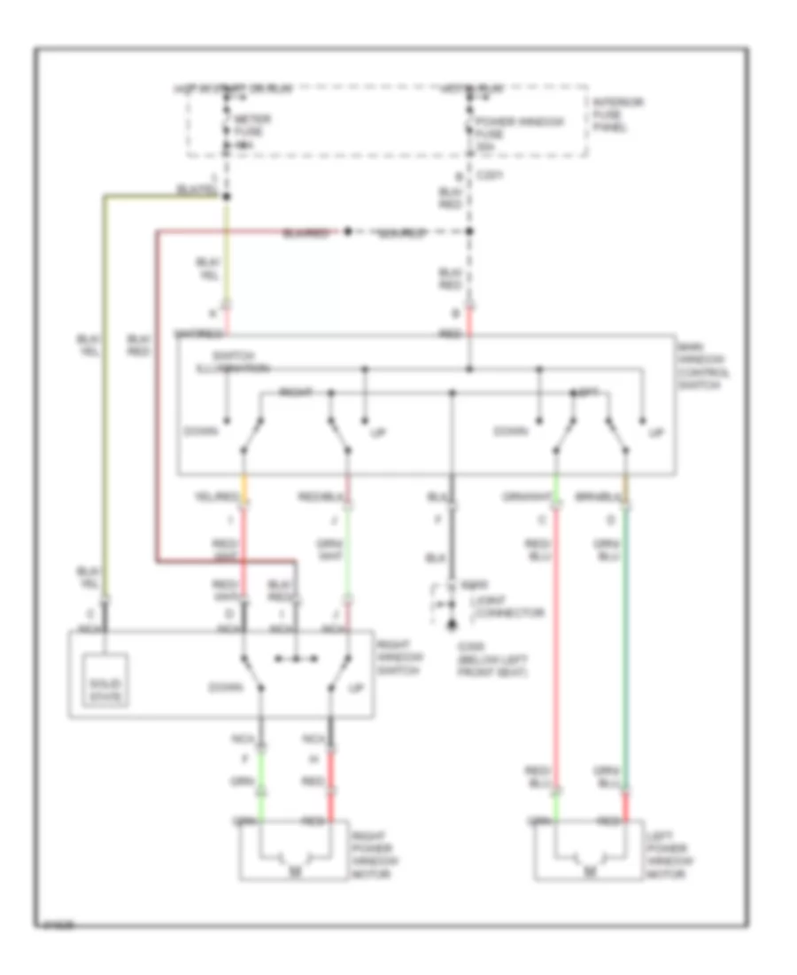
POWER WINDOWS
Power Window Wiring Diagram for Ford Probe GT 1993
 https://portal-diagnostov.com/license.html
Automotive Electricians Portal FZCO
Automotive Electricians Portal FZCO
https://portal-diagnostov.com/license.html
https://portal-diagnostov.com/license.html
Automotive Electricians Portal FZCO
Automotive Electricians Portal FZCOList of elements for Power Window Wiring Diagram for Ford Probe GT 1993:
- C201 b
- C300
- Down
- G300 (below left front seat)
- Hot in run
- Hot in start or run
- Interior fuse panel
- Joint connector
- Left
- Left power window motor
- Main window control switch
- Meter fuse 15a
- Nca
- Power window fuse 30a
- Red
- Right
- Right power window motor
- Right window switch
- Solid state
- Switch illumination
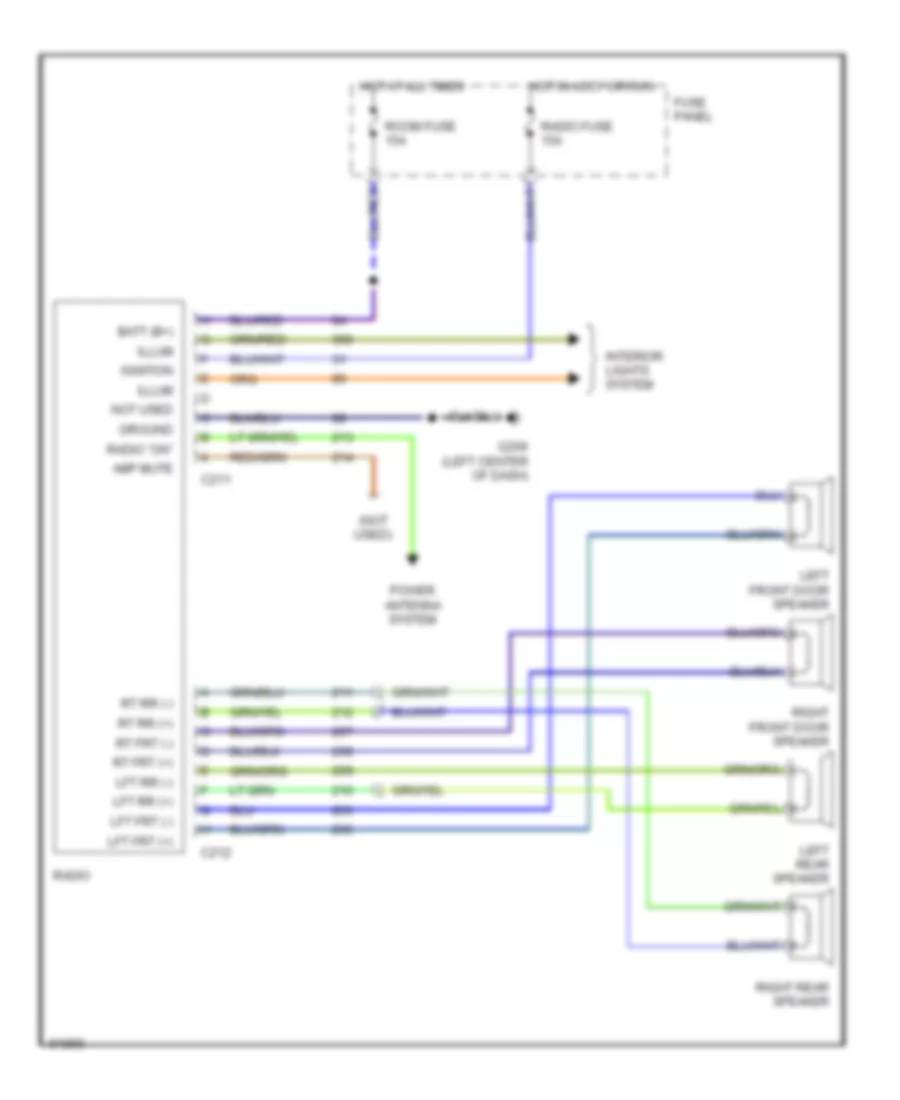
RADIO
Radio Wiring Diagrams for Ford Probe GT 1993
 https://portal-diagnostov.com/license.html
Automotive Electricians Portal FZCO
Automotive Electricians Portal FZCO
https://portal-diagnostov.com/license.html
https://portal-diagnostov.com/license.html
Automotive Electricians Portal FZCO
Automotive Electricians Portal FZCOList of elements for Radio Wiring Diagrams for Ford Probe GT 1993:
- (not used)
- Amp mute
- Batt (b+)
- C211
- C212
- Fuse panel
- G206 (left center of dash)
- Ground
- Hot at all times
- Hot in accy or run
- Ignition
- Illum
- Interior lights system
- Left front door speaker
- Left rear speaker
- Lft frt (+)
- Lft frt (-)
- Lft rr (+)
- Lft rr (-)
- Not used
- Power antenna system
- Radio
- Radio "on"
- Radio fuse 15a
- Right front door speaker
- Right rear speaker
- Room fuse 15a
- Rt frt (+)
- Rt frt (-)
- Rt rr (+)
- Rt rr (-)
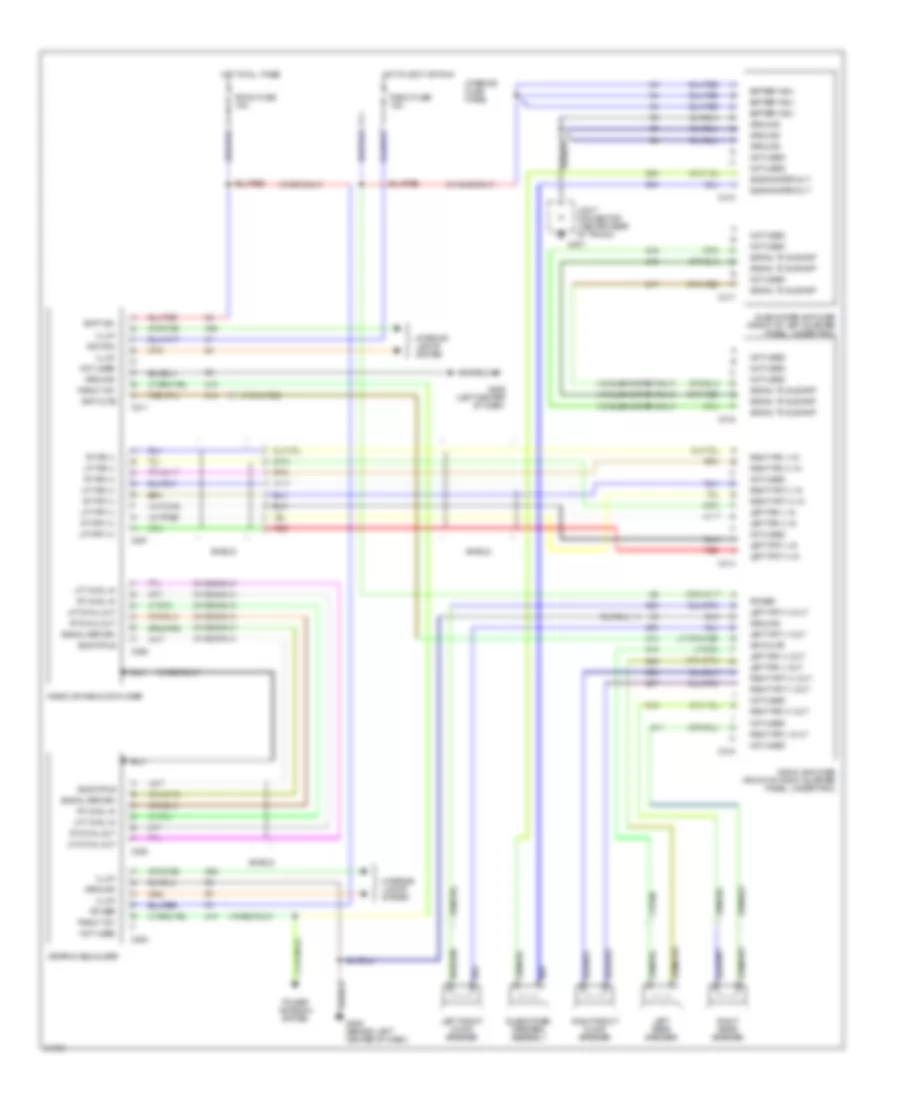
Radio Wiring Diagrams, Premium Radio for Ford Probe GT 1993
 https://portal-diagnostov.com/license.html
Automotive Electricians Portal FZCO
Automotive Electricians Portal FZCO
https://portal-diagnostov.com/license.html
https://portal-diagnostov.com/license.html
Automotive Electricians Portal FZCO
Automotive Electricians Portal FZCOList of elements for Radio Wiring Diagrams, Premium Radio for Ford Probe GT 1993:
- (w/ eq only)
- (w/ sub only)
- (w/ subwoofer only)
- Amp mute
- Batt (b+)
- Battery (b+)
- C211
- C253
- C254
- C291
- C292
- C314
- C315
- C316
- C317
- C318
- Eq status
- G206 (behind left center of dash)
- G206 (left center of dash)
- G407
- Graphic equalizer
- Ground
- Hot at all times
- Hot in accy or run
- Ignition
- Illum
- Interior fuse panel
- Interior lights system
- Joint connector (center rear of trunk)
- Left front door speaker
- Left frt (+) in
- Left frt (+) out
- Left frt (-) in
- Left frt (-) out
- Left rear speaker
- Left rr (+) in
- Left rr (+) out
- Left rr (-) in
- Left rr (-) out
- Lft chnl in
- Lft chnl out
- Lft frt (+)
- Lft frt (-)
- Lft rr (+)
- Lft rr (-)
- Not used
- Power
- Power antenna system
- Radio "on"
- Radio amplifier (front of right quarter panel, under trim)
- Radio fuse 15a
- Radio or radio/cd player
- Red
- Right front door speaker
- Right frt (+) in
- Right frt (+) out
- Right frt (-) in
- Right frt (-) out
- Right rear speaker
- Right rr (+) in
- Right rr (+) out
- Right rr (-) in
- Right rr (-) out
- Room fuse 15a
- Rt chnl in
- Rt chnl out
- Rt frt (+)
- Rt frt (-)
- Rt rr (+)
- Rt rr (-)
- Shield
- Signal return
- Signal to sub amp
- Subwoofer amplifier (front of left quarter panel, under trim)
- Subwoofer out
- Subwoofer speaker assembly
STARTING/CHARGING
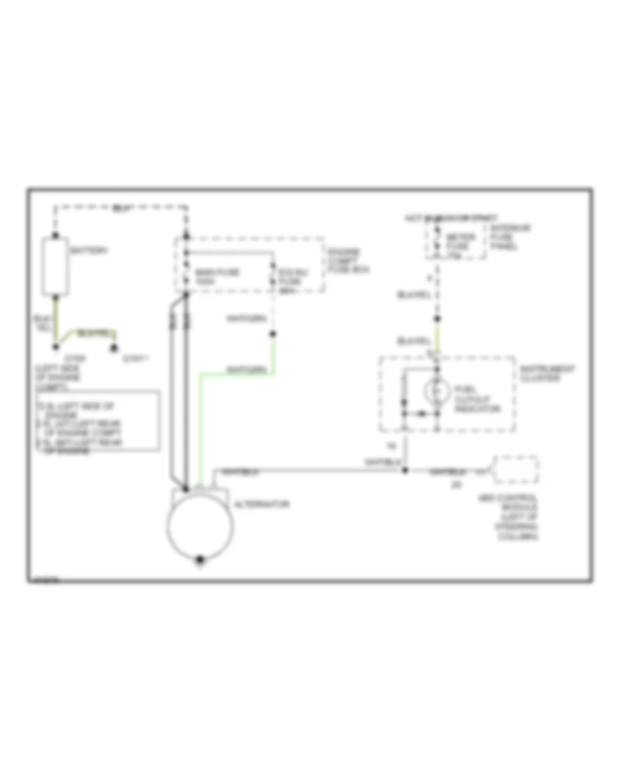
Charging Wiring Diagram for Ford Probe GT 1993
 https://portal-diagnostov.com/license.html
Automotive Electricians Portal FZCO
Automotive Electricians Portal FZCO
https://portal-diagnostov.com/license.html
https://portal-diagnostov.com/license.html
Automotive Electricians Portal FZCO
Automotive Electricians Portal FZCOList of elements for Charging Wiring Diagram for Ford Probe GT 1993:
- *2.0l-left side of engine 2.5l (a/t)-left rear of engine compt 2.5l (m/t)-left rear of engine
- (left side of engine compt)
- Abs control module (left of steering column)
- Alternator
- Battery
- Egi inj fuse 30a
- Engine compt fuse box
- Fuel cutout indicator
- G100
- G101
- Hot in run or start
- Instrument cluster
- Interior fuse panel
- Main fuse 100a
- Meter fuse 15a
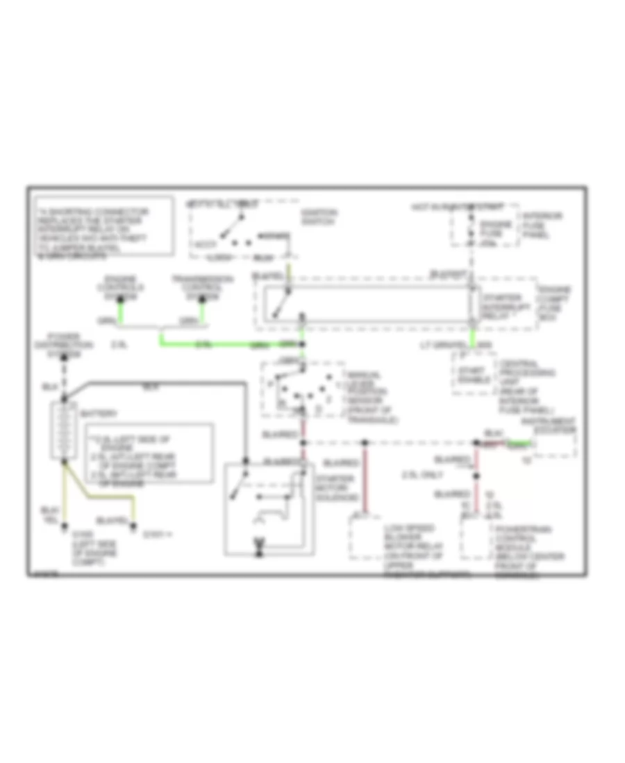
Starting Wiring Diagram, A/T for Ford Probe GT 1993
 https://portal-diagnostov.com/license.html
Automotive Electricians Portal FZCO
Automotive Electricians Portal FZCO
https://portal-diagnostov.com/license.html
https://portal-diagnostov.com/license.html
Automotive Electricians Portal FZCO
Automotive Electricians Portal FZCOList of elements for Starting Wiring Diagram, A/T for Ford Probe GT 1993:
- **2.0l-left side of engine 2.5l (a/t)-left rear of engine compt 2.5l (m/t)-left rear of engine
- 1c 1d
- 2.0l
- 2.5l
- 2.5l 2.0l
- 2.5l only
- Accy
- Battery
- Central processing unit (rear of interior fuse panel)
- Engine compt fuse box
- Engine controls system
- Engine fuse 15a
- G100 (left side of engine compt)
- G101
- Hot at all times
- Hot in run or start
- Ignition switch
- Instrument cluster
- Interior fuse panel
- Lock
- Low speed blower motor relay (on front of upper radiator support)
- Manual lever position sensor (front of transaxle)
- Power distribution system
- Powertrain control module (below center front of console)
- Red
- Run
- Start
- Start enable
- Starter interrupt relay
- Starter motor/ solenoid
- Transmission control system
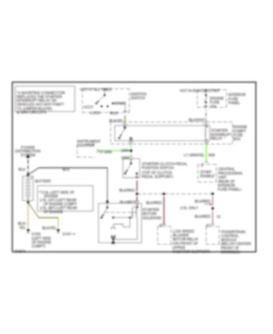
Starting Wiring Diagram, M/T for Ford Probe GT 1993
 https://portal-diagnostov.com/license.html
Automotive Electricians Portal FZCO
Automotive Electricians Portal FZCO
https://portal-diagnostov.com/license.html
https://portal-diagnostov.com/license.html
Automotive Electricians Portal FZCO
Automotive Electricians Portal FZCOList of elements for Starting Wiring Diagram, M/T for Ford Probe GT 1993:
- **2.0l-left side of engine 2.5l (a/t)-left rear of engine compt 2.5l (m/t)-left rear of engine
- 2.5l only
- Accy
- Battery
- Central processing unit (rear of interior fuse panel)
- Engine compt fuse box
- Engine fuse 15a
- G100 (left side of engine compt)
- G101
- Hot at all times
- Hot in run or start
- Ignition switch
- Instrument cluster
- Interior fuse panel
- Lock
- Low speed blower motor relay (on front of upper radiator support)
- Power distribution system
- Powertrain control module (below center front of console)
- Run
- Start
- Start enable
- Starter clutch pedal position switch (top of clutch pedal support)
- Starter interrupt relay
- Starter motor/ solenoid
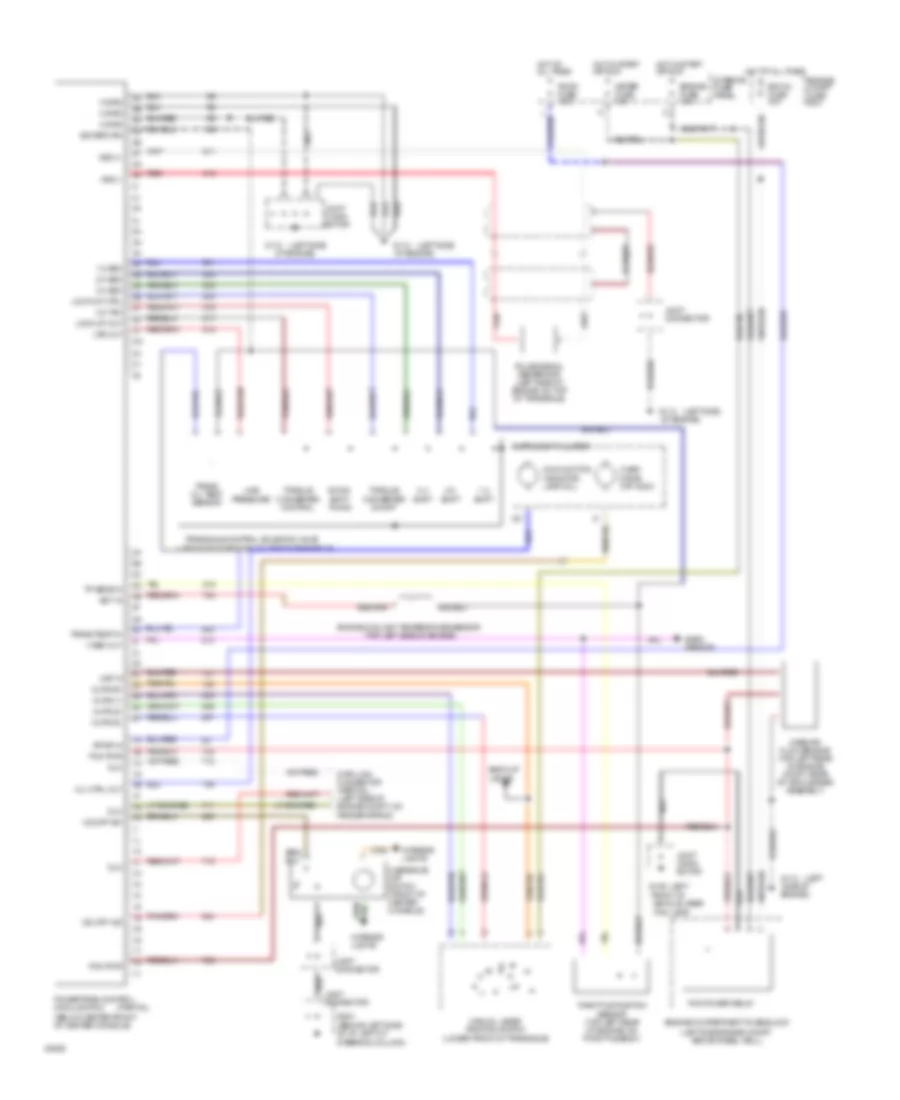
TRANSMISSION
2.0L
2.0L, Transmission Wiring Diagram for Ford Probe GT 1993
 https://portal-diagnostov.com/license.html
Automotive Electricians Portal FZCO
Automotive Electricians Portal FZCO
https://portal-diagnostov.com/license.html
https://portal-diagnostov.com/license.html
Automotive Electricians Portal FZCO
Automotive Electricians Portal FZCOList of elements for 2.0L, Transmission Wiring Diagram for Ford Probe GT 1993:
-
- (left side of engine, on top of transaxle)
- 1g
- 2a
- 2b
- 2g
- 2h
- 3l
- 3y
- (behind left side of i/p, left of steering column)
- (below center front of center console)
- (left
- (left side
- (left side engine compt, above wheel well)
- (partial)
- (top left side of engine)
- 1-2 shift
- 1-2 sso
- 2-3 shift
- 2-3 sso 3r
- 3-2 tso 3u
- 3-4 shift
- 3-4 sso 3s
- Back-up lights
- Baro sensor
- Data link connector (partial) (left side of engine compt, on fender apron)
- Dlc
- Dlc 1h
- Down- shift timing
- Ect in
- Egi inj fuse 30a
- Engine compartment fuse block
- Engine compt fuse box
- Engine coolant temperature sensor
- Engine fuse 15a
- Fog lamp)
- Front of
- G106
- G112
- G204
- Hot at all times
- Hot in start or run
- Instrument cluster
- Interior fuse panel
- Interior lights
- Joint conn- ector
- Joint connector
- Kpwr in
- Line pressure
- Lock-up ctrl 3t
- Lock-up out 3v
- Lps out 3w
- M grd
- Maf in
- Malfunction indicator lamp (mil)
- Manual lever position switch (lower front of transaxle)
- Mass air flow sensor (top left rear of engine compt, rear of air cleaner assembly)
- Meter fuse 15a
- Mil ctrl out
- Mlps (1)
- Mlps (2) 2p
- Mlps (d)
- Mlps (r)
- O/d off ind
- O/d off sw
- Of engine)
- Over- drive off indic
- Overdrive off switch (front of center console)
- Pcm power relay
- Pcm pwr
- Pcm pwr 1c
- Powertrain control module (pcm)
- Pulse signal generator (left side of engine, on top of transaxle)
- Red
- Room fuse 15a
- Side of engine)
- Sig return
- Throttle position sensor (top left rear of engine, on throttle body)
- Torque converter control
- Torque converter on/off
- Tp sens in 2e
- Trans oil temp sensor
- Trans temp in 2i
- Transaxle control solenoid valve
- V ref out 2j
- Vehicle, near
- Vss (+)
- Vss (-)
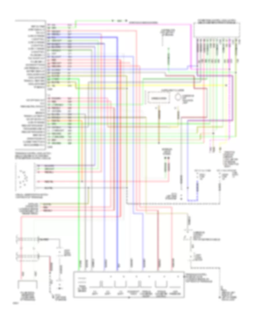
2.5L
2.5L, Transmission Wiring Diagram for Ford Probe GT 1993
 https://portal-diagnostov.com/license.html
Automotive Electricians Portal FZCO
Automotive Electricians Portal FZCO
https://portal-diagnostov.com/license.html
https://portal-diagnostov.com/license.html
Automotive Electricians Portal FZCO
Automotive Electricians Portal FZCOList of elements for 2.5L, Transmission Wiring Diagram for Ford Probe GT 1993:
- (lh side of engine compartment, on fender apron)
- (top left frt
- (top left rr of engine on throttle body)
- 1-2 shift
- 1-2 shift sol
- 2-3 shift
- 2-3 shift sol
- 3-4 shift
- 3-4 shift sol
- Baro sig in
- Battery back-up
- Brake in
- C246
- C247
- C248
- C258
- C259
- Closed throttle in
- Crank pos sig in
- Data link connector
- Distributor
- Dlc
- Downshift timing
- Exterior lights system
- Fuse block: i/p
- G
- G112 (left side of engine)
- G204 (behind left side of i/p, left of steer- ing column)
- Hot at all times
- Hot in run or start
- I
- Instrument cluster
- Joint conn- ector
- Line press sol out
- Line pressure
- Manual lever position switch (top front of transaxle)
- Meter fuse 15a
- Mlps ('1' range)
- Mlps ('2' range)
- Mlps ('d' range)
- Mlps ('r' range)
- Module ground
- Module power
- O/d off indic out
- O/d off switch in
- Of engine)
- Overdrive control switch (frt of center console)
- Overdrive off indicator lamp
- Park/neutral pos out
- Powertrain control module (pcm) (below center of front console)
- Pulse gen (+)
- Pulse gen (-)
- Pulse signal generator (lower rear of transaxle)
- Red
- Red
- Reduce torque sig 1
- Reduce torque sig 2
- Ref voltage
- Room fuse 15a
- Speedometer
- Start signal in
- Starting/charging system
- Tcc on/off out
- Tcc out
- Throttle position sensor
- Torque converter control
- Torque converter on/off
- Torque reduced in
- Tp sens in
- Trans fluid temp in
- Trans oil temp grd
- Trans oil temp sensor
- Transaxle control module (tcm) (below center of i/p, forward of powertrain control module)
- Transaxle control solenoid valve (lh side of engine, on top front of transaxle)
- Vehicle speed in (+)
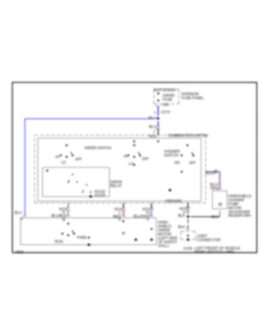
WIPER/WASHER
2-Speed Wiper/Washer Wiring Diagram for Ford Probe GT 1993
 https://portal-diagnostov.com/license.html
Automotive Electricians Portal FZCO
Automotive Electricians Portal FZCO
https://portal-diagnostov.com/license.html
https://portal-diagnostov.com/license.html
Automotive Electricians Portal FZCO
Automotive Electricians Portal FZCOList of elements for 2-Speed Wiper/Washer Wiring Diagram for Ford Probe GT 1993:
- (left front of vehicle, near left fog lamp)
- 20a
- C214
- Combination switch
- G106
- Ground
- Hot in run
- Interior fuse panel
- Joint connector
- M nca
- Nca
- Nca l red a
- Off
- Park
- Run
- Solid state
- Washer switch
- Wind- shield wiper motor (left side of safety wall)
- Windshield washer pump motor (in washer reservoir)
- Wiper fuse
- Wiper relay
- Wiper switch
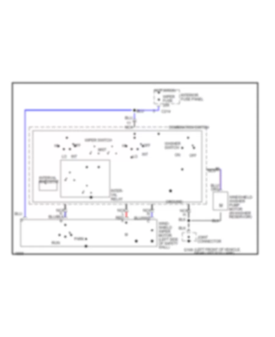
Interval Wiper/Washer Wiring Diagram for Ford Probe GT 1993
 https://portal-diagnostov.com/license.html
Automotive Electricians Portal FZCO
Automotive Electricians Portal FZCO
https://portal-diagnostov.com/license.html
https://portal-diagnostov.com/license.html
Automotive Electricians Portal FZCO
Automotive Electricians Portal FZCOList of elements for Interval Wiper/Washer Wiring Diagram for Ford Probe GT 1993:
- (left front of vehicle, near left fog lamp)
- C214
- Combination switch
- G106
- Ground
- Hot in run
- Int
- Inter- val relay
- Interior fuse panel
- Interval rheostat
- Joint connector
- M nca
- Mist
- Nca
- Nca l red a
- Off
- Park
- Run
- Washer switch
- Wind- shield wiper motor (left side of safety wall)
- Windshield washer pump motor (in washer reservoir)
- Wiper fuse 20a
- Wiper switch
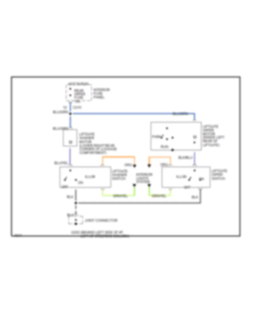
Rear Wiper/Washer Wiring Diagram for Ford Probe GT 1993
 https://portal-diagnostov.com/license.html
Automotive Electricians Portal FZCO
Automotive Electricians Portal FZCO
https://portal-diagnostov.com/license.html
https://portal-diagnostov.com/license.html
Automotive Electricians Portal FZCO
Automotive Electricians Portal FZCOList of elements for Rear Wiper/Washer Wiring Diagram for Ford Probe GT 1993:
- C215
- G202 (behind left side of i/p, left of steering column)
- Hot in run
- Illum
- Interior fuse panel
- Interior lights system
- Joint connector
- Liftgate washer motor (lower right rear corner of luggage compartment)
- Liftgate washer switch
- Liftgate wiper motor (inside left rear of liftgate)
- Liftgate wiper switch
- Off
- Park
- Rear wiper fuse 15a
- Run

 Čeština
 Dansk
Dansk Deutsch
 Ελληνικά
 English
 English
 Español
 Suomi
Suomi Français
 Français
 עברית
עברית Hrvatski
 Magyar
 Italiano
 한국어
한국어 Nederlands
 Polski
 Português
 Português
 Română
 Русский
 Slovenčina
 Slovenščina
 Svenska
 Türkçe
 中文 (中国)
