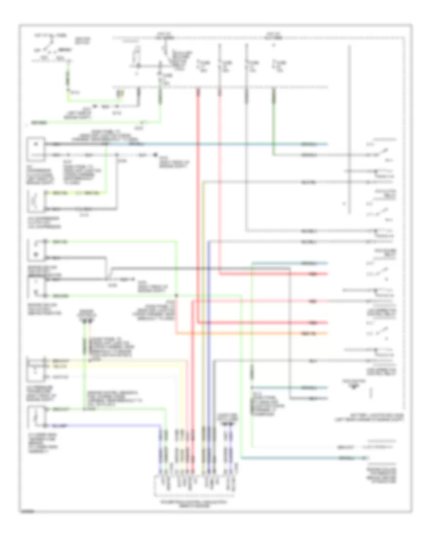
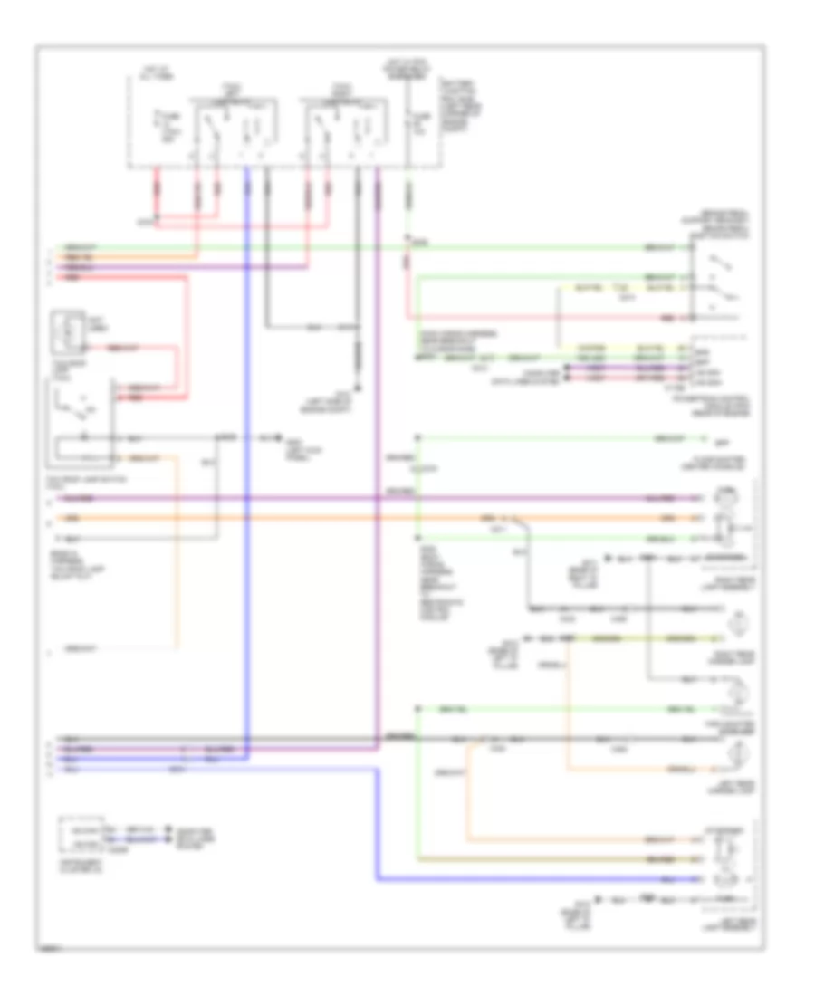
AIR CONDITIONING
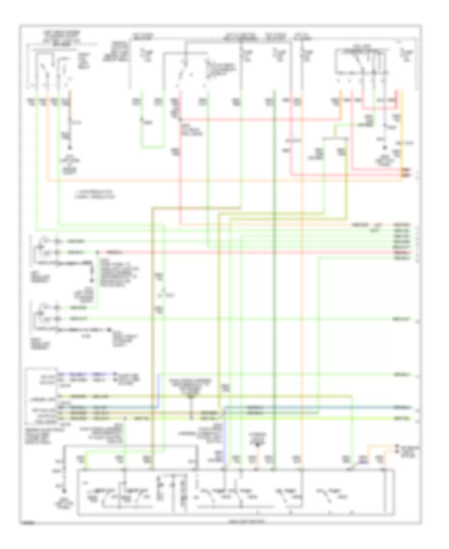
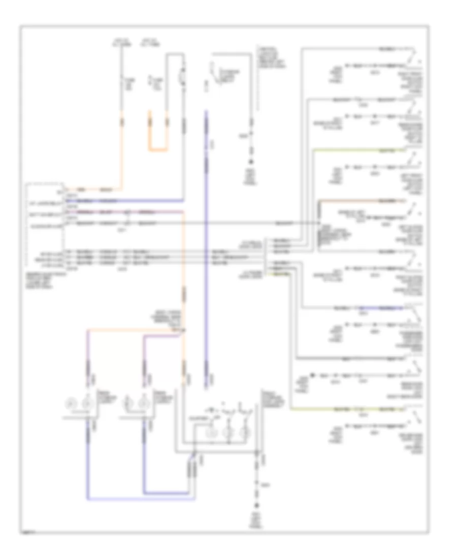
Manual A/C Wiring Diagram (1 of 2) for Ford Transit Connect XLT Premium 2013
 https://portal-diagnostov.com/license.html
Automotive Electricians Portal FZCO
Automotive Electricians Portal FZCO
https://portal-diagnostov.com/license.html
https://portal-diagnostov.com/license.html
Automotive Electricians Portal FZCO
Automotive Electricians Portal FZCO
List of elements for Manual A/C Wiring Diagram (1 of 2) for Ford Transit Connect XLT Premium 2013:
- (left kick panel) g200
- 15-fa2b
- 32-fa76
- 33-fa76
- 4-ec14
- 5-ec14
- 7-fa11
- 91s-fa20
- 91s-fa9
- A/c compressor cycling switch (right rear of engine compt)
- A/c cycling sw
- A/c request
- A/c switch
- A/c telltale
- Air inlet mode door actuator (right side of dash)
- Air inlet mode switch
- Auxiliary blower motor assembly
- Auxiliary blower motor switch
- Battery junction box (bjb) (left rear corner of engine compt)
- Block connector (taxi)
- Blower motor (right side of dash)
- Blower motor relay
- Blower motor resistor (near blower motor)
- Blower motor switch 1) off 2) low 3) medium low 4) medium high 5) high
- Blower on
- C201b
- C201c
- C201e
- C213
- C220a
- C327
- C3508a
- C3508b
- C3508c
- Central junction box (cjb) (behind left side of dash)
- Computer data lines system
- Defrost
- Function selector switch
- Fuse 10a
- Fuse 20a
- Fuse 30a
- Fuse 7.5a
- G103 (right front of engine compt)
- G200 (left kick panel)
- G203 (right kick panel)
- Generic electronic module (gem) (lower left side of dash)
- High
- Hot at all times
- Hot in run or start
- Instrument cluster (ic)
- Interior lights system
- Low
- Medium
- Ms can+
- Ms can-
- Off
- Power distribution system
- Recirc ccw
- Recirc cw
- Recirc sw
- Recirc telltale
- Recirculation request
- Red
- S106
- S208
- S220
- S225 (main wiring harness, near breakout to air inlet mode door actuator)
- S228
- S229 (main wiring harness, near breakout to data link connector)
- Thermal limiter
- Vpwr
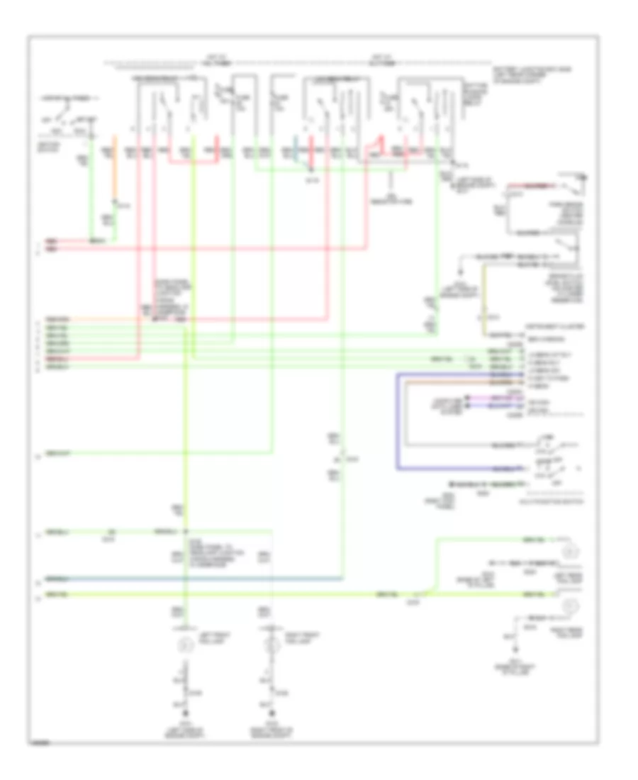
Manual A/C Wiring Diagram (2 of 2) for Ford Transit Connect XLT Premium 2013
 https://portal-diagnostov.com/license.html
Automotive Electricians Portal FZCO
Automotive Electricians Portal FZCO
https://portal-diagnostov.com/license.html
https://portal-diagnostov.com/license.html
Automotive Electricians Portal FZCO
Automotive Electricians Portal FZCOList of elements for Manual A/C Wiring Diagram (2 of 2) for Ford Transit Connect XLT Premium 2013:
- (dash panel to headlamp junction wiring harness, near breakout to horn)
- (dash panel to headlamp junction wiring harness, near breakout to horn) s107
- (engine control sensor & fuel charge wiring harness, near breakout to coil on plug 3) s124
- 30-pa7
- 31-pa17
- 4-ec7
- 5-ec7
- 7-fa88
- 8-fa88
- 9-fa1
- 91s-re8
- 91s-rh9
- A/c clutch relay
- A/c compressor clutch coil (a/c compressor)
- A/c compressor clutch diode (left front of engine compt)
- A/c pressure transducer (right front of engine compt)
- Acc
- Accr
- Acpt
- Auxiliary blower motor relay (taxi)
- Battery junction box (bjb) (left rear corner of engine compt)
- C110
- C175b
- C175e
- C215
- Cht
- Computer data lines system
- Cooling fan diode
- Cylinder head temperature sensor (cylinder head assembly)
- Engine controls system
- Engine cooling fan motor 1 (behind radiator)
- Engine cooling fan motor 2 (behind radiator)
- Engine cooling fan resistor (behind center of radiator)
- Fuse 10a
- Fuse 30a
- Fuse 40a
- Fuse 50a
- G101 (left side of engine compt)
- G103 (right front of engine compt)
- Hfc
- High speed fan control relay
- Hot at all times
- Hs ca+
- Hs can-
- Ignition switch
- Lfc
- Low speed fan control relay
- Nca
- Off
- Pcm power relay
- Pcmrc
- Powertrain control module (pcm) (rear of engine)
- Re405
- Red
- Run
- S104
- S106
- S108 (dash panel to headlamp junction wiring harness, near breakout to horn)
- S115
- S118
- S127
- Sigrtn
- Start
- Ve712
- Vref
ANTI-LOCK BRAKES
Anti-lock Brakes Wiring Diagram for Ford Transit Connect XLT Premium 2013
 https://portal-diagnostov.com/license.html
Automotive Electricians Portal FZCO
Automotive Electricians Portal FZCO
https://portal-diagnostov.com/license.html
https://portal-diagnostov.com/license.html
Automotive Electricians Portal FZCO
Automotive Electricians Portal FZCOList of elements for Anti-lock Brakes Wiring Diagram for Ford Transit Connect XLT Premium 2013:
- (left rear of engine compt)
- (left side of engine compt)
- (main wiring harness, near breakout to microphone) s234
- 15-ce8
- 15-cf6
- 15s-lg23
- 30-cf13
- 30-cf6
- 4-cf67
- 4-ec7
- 5-cf67
- 5-ec7
- 7-cf67
- 8-cf32
- 8-cf34
- 8-cf38
- 8-cf40
- 9-cf1
- 9-cf32
- 9-cf34
- 9-cf38
- 9-cf40
- 9-cf67
- 91-ce8
- 91-cf13
- 91-cf6
- 91s-pg6
- Abs test connector
- Abs test connector c126
- Anti-lock brake system (abs) control module (left rear of engine compt)
- Battery junction box (bjb) (left rear corner of engine compt)
- Bpp
- Bps
- Brake fluid level switch (on master cylinder reservoir)
- Brake pedal position switch (brake pedal support bracket)
- Brake warning
- C175b
- C213
- C215
- C216
- C219
- C220b
- C432
- Central junction box (cjb) (behind left side of dash)
- Clus gnd
- Clus pwr
- Computer data lines system
- Exterior lights system
- Fuse 10a
- Fuse 15a
- Fuse 20a
- Fuse 30a
- Fuse 7.5a
- G101 (left side of engine compt)
- G102
- G106 (left side of engine compt)
- G203 (right kick panel)
- Gnd
- Hot at all times
- Hot in start or run
- Hot w/ pcm power relay energized
- Hs can yaw+
- Hs can yaw-
- Hs can+
- Hs can-
- Ign
- Instrument cluster (ic)
- Left front wheel speed sensor (left front wheel hub)
- Left rear wheel speed sensor (left rear wheel hub)
- Lf whl spd+
- Lf whl spd-
- Lr whl spd+
- Lr whl spd-
- Nca
- Park brake switch (center console)
- Powertrain control module (pcm) (rear of engine)
- Red
- Rf whl spd+
- Rf whl spd-
- Right front wheel speed sensor (right front wheel hub)
- Right rear wheel speed sensor (right rear wheel hub)
- Rr whl spd+
- Rr whl spd-
- S111
- S115
- S152
- S220
- S236
- S280
- Solid state
- Stability control sensor module (center console)
- Steering angle sensor module (sasm) (steering column)
- Vbat
ANTI-THEFT
Forced Entry Wiring Diagram for Ford Transit Connect XLT Premium 2013
 https://portal-diagnostov.com/license.html
Automotive Electricians Portal FZCO
Automotive Electricians Portal FZCO
https://portal-diagnostov.com/license.html
https://portal-diagnostov.com/license.html
Automotive Electricians Portal FZCO
Automotive Electricians Portal FZCOList of elements for Forced Entry Wiring Diagram for Ford Transit Connect XLT Premium 2013:
- (body wiring harness, near breakout to c339)
- (body wiring harness, near breakout to restraints control module) s311
- (not used)
- (right kick panel)
- 10-aa36
- 29-aa17
- 31s-aa17
- 31s-aa63
- 31s-aa64
- 31s-gl16
- 31s-gl20
- 31s-gl9
- 32-aa27
- 32-aa59
- 32aa-59
- 33-aa59
- 4-ec14
- 5-ec14
- All lock
- C201a
- C201b
- C201c
- C201d
- C201e
- C211
- C219
- C237
- C241
- C421
- C510
- C610
- Central junction box (cjb) (behind left side of dash)
- Computer data lines system
- Door unlock
- Dr ajar
- Driver side door lock unit (driver's door)
- Early production
- Fuse 20a
- G200 (left kick panel)
- G300
- G300 (right kick panel)
- G301 (left kick panel)
- G410 (base of left "d" pillar)
- G411 (base of right "d" pillar)
- Generic electronic module (gem) (lower left side of dash)
- Hot at all times
- Left sliding door ajar switch (base of left "c" pillar)
- Left sliding door contact switch (base of left "b" pillar)
- Left sliding door lock actuator (lower rear of sliding door)
- Lf dr ajar
- Lock pos
- Lock sw
- Ms can (+)
- Ms can (-)
- Nca
- Not used
- Passenger side door lock unit (passenger's door)
- Rear door lock unit
- Rear door unlock relay
- Rear dr ajar
- Red
- Rf dr ajar
- Right sliding door ajar switch (base of right "c" pillar)
- Right sliding door contact switch (base of right "b" pillar)
- Right sliding door lock actuator (lower rear of sliding door)
- Rke antenna
- S228
- S300
- S301
- S303
- S307 (body wiring harness, near breakout to restraints control module)
- S309 (body wiring harness, near breakout to c219)
- S312
- S315
- S501
- S600
- Unlock cabin
- Unlock rear
- Unlock sw
- Vbatt lock
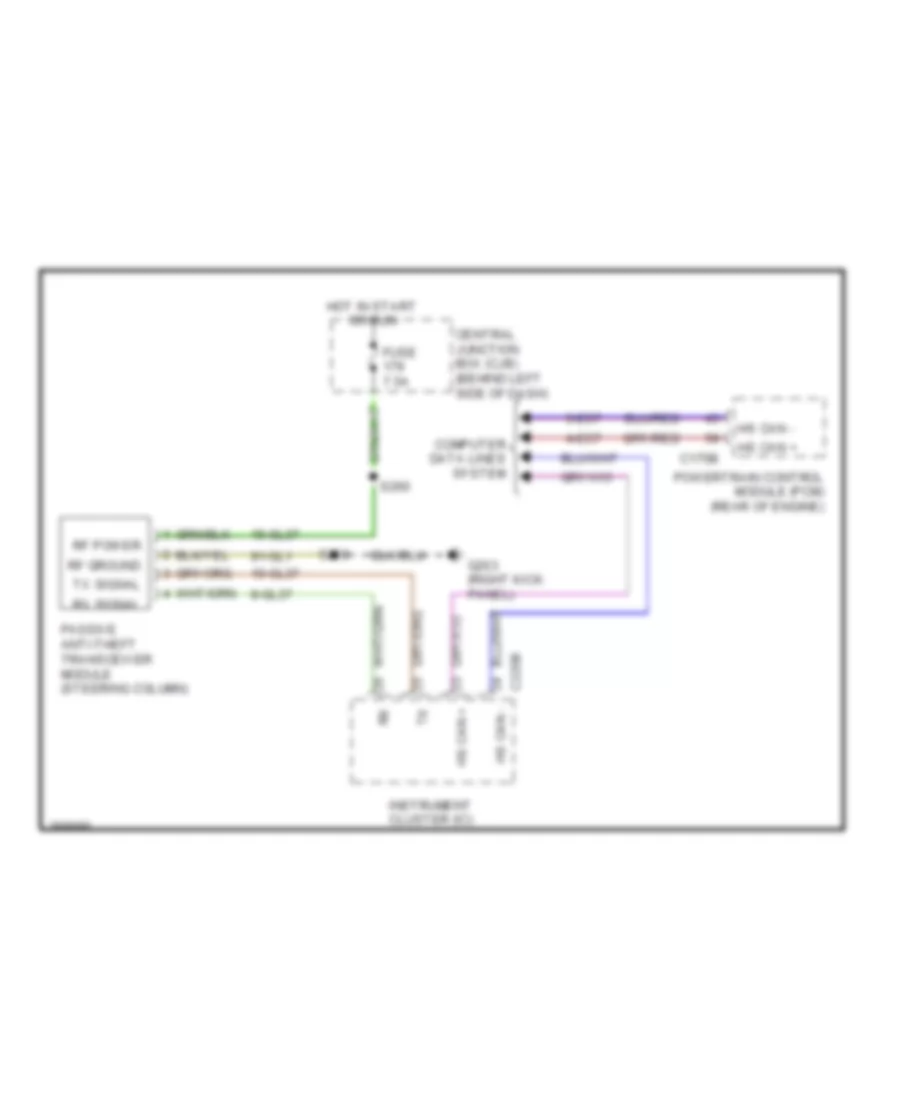
Passive Anti-theft Wiring Diagram for Ford Transit Connect XLT Premium 2013
 https://portal-diagnostov.com/license.html
Automotive Electricians Portal FZCO
Automotive Electricians Portal FZCO
https://portal-diagnostov.com/license.html
https://portal-diagnostov.com/license.html
Automotive Electricians Portal FZCO
Automotive Electricians Portal FZCOList of elements for Passive Anti-theft Wiring Diagram for Ford Transit Connect XLT Premium 2013:
- 10-gl37
- 15-gl37
- 4-ec7
- 5-ec7
- 8-gl37
- 91-gl1
- C175b
- C220b
- Central junction box (cjb) (behind left side of dash)
- Computer data lines system
- Fuse 7.5a
- G203 (right kick panel)
- Hot in start or run
- Hs can +
- Hs can -
- Instrument cluster (ic)
- Passive anti-theft transceiver module (steering column)
- Powertrain control module (pcm) (rear of engine)
- Rf ground
- Rf power
- Rx signal
- S220
- S260
- Tx signal
BODY CONTROL MODULES
Body Control Modules Wiring Diagram (1 of 2) for Ford Transit Connect XLT Premium 2013
 https://portal-diagnostov.com/license.html
Automotive Electricians Portal FZCO
Automotive Electricians Portal FZCO
https://portal-diagnostov.com/license.html
https://portal-diagnostov.com/license.html
Automotive Electricians Portal FZCO
Automotive Electricians Portal FZCOList of elements for Body Control Modules Wiring Diagram (1 of 2) for Ford Transit Connect XLT Premium 2013:
- 15-dk20
- 15-ka28
- 15-ka9
- 15s-hb20
- 15s-ld13
- 15s-ld7
- 15s-le14
- 15s-lg28
- 31s-gj7
- 31s-hb22
- 31s-hb7
- 31s-hb9
- 32-aa63
- 32-ka11
- 32-ka28
- 32-ka34
- 32-ka9
- 33-ka34
- 4-ec14
- 49s-lg1
- 49s-lg18
- 5-ec14
- 8-ka46
- 8-ka47
- 91-dk20
- 91s-lg8
- C201a
- C201b
- Central junction box (cjb) (behind left side of dash)
- Computer data lines system
- Defogger system
- Defrost rlc
- Defrost sw
- Door locks system
- Exterior lights system
- Fr fog lamp
- Front wiper hi
- Front wiper int 2
- Front wiper int 3
- Front wiper low
- Front wiper park position
- Front wiper washer sw
- Fuse 20a
- Fuse 7.5a
- G203 (right kick panel)
- Generic electronic module (gem) (lower left side of dash)
- Hazard sw
- Headlapms on
- Headlights system
- Horn sw
- Horns system
- Hot in run and start
- Hws button
- Hws rly ctrl
- Ign front wiper
- Ign sw
- Left turn
- Ms can +
- Ms can -
- Rear wiper washer sw
- Reverse sw
- Right turn
- Rr fog lamp
- Rr wiper output
- S220
- S231
- S239
- S260
- Sig gnd
- Unlock front dr
- Wiper/washer system
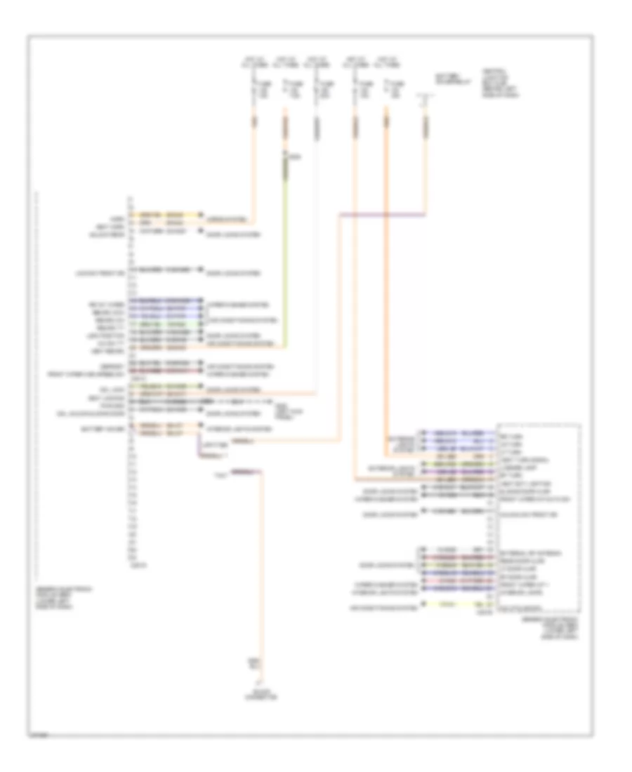
Body Control Modules Wiring Diagram (2 of 2) for Ford Transit Connect XLT Premium 2013
 https://portal-diagnostov.com/license.html
Automotive Electricians Portal FZCO
Automotive Electricians Portal FZCO
https://portal-diagnostov.com/license.html
https://portal-diagnostov.com/license.html
Automotive Electricians Portal FZCO
Automotive Electricians Portal FZCOList of elements for Body Control Modules Wiring Diagram (2 of 2) for Ford Transit Connect XLT Premium 2013:
- 10-aa36
- 15-fa28
- 29-aa17
- 29-dk20
- 29-gj6
- 29-gj8
- 29-lc7
- 29-le29
- 29-lg26
- 29s-lf25
- 31-dk20
- 31-ka8
- 31s-aa17
- 31s-aa63
- 31s-aa64
- 31s-gl16
- 31s-gl20
- 31s-gl9
- 31s-lc18
- 32-aa27
- 32-aa59
- 32-fa76
- 33-aa59
- 33-fa76
- 49s-lg12
- 49s-lg19
- 49s-lg2
- 49s-lg5
- 7-fa11
- 8-ka45
- 91s-fa20
- 91s-fa9
- 91s-ka11
- 91s-ka35
- A/c cycling sw
- A/c sw tt
- Air conditioning system
- Battery saver
- Battery saver relay
- Block connector
- C201c
- C201d
- C201e
- Cdl lock
- Cdl unlock sliding door
- Central junction box (cjb) (behind left side of dash)
- Defrost
- Door locks system
- Exterior lights system
- External rf antenna
- Front wiper high speed sw
- Front wiper int 1
- Front wiper int/auto sw
- Fuse 10a
- Fuse 15a
- Fuse 20a
- Fuse 7.5a
- G200 (left kick panel)
- Generic electronic module (gem) (lower left side of dash)
- Horn
- Horns system
- Hot at all times
- Interior lamps
- Interior lights system
- Lf door ajar
- Lf turn
- License lamp
- Lock position
- Lock sw front dr
- Lr turn
- Pwr gnd
- Rear door ajar
- Recirc ccw
- Recirc cw
- Recirc tt
- Rf door ajar
- Rf turn
- Rr int wiper
- Rr turn
- S228
- S235
- Sliding door ajar
- Taxi
- Unlock rear
- Unlock sw front dr
- Upfitter
- Vbat ext lighting
- Vbat horn
- Vbat locking
- Vbat recirc
- Vbat turn signal
- Wiper/washer system
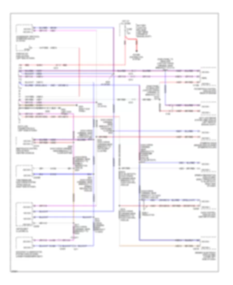
COMPUTER DATA LINES
Computer Data Lines Wiring Diagram for Ford Transit Connect XLT Premium 2013
 https://portal-diagnostov.com/license.html
Automotive Electricians Portal FZCO
Automotive Electricians Portal FZCO
https://portal-diagnostov.com/license.html
https://portal-diagnostov.com/license.html
Automotive Electricians Portal FZCO
Automotive Electricians Portal FZCOList of elements for Computer Data Lines Wiring Diagram for Ford Transit Connect XLT Premium 2013:
- (dash panel to headlamp junction wiring harness, in breakout to c215) s117
- (dash panel to headlamp junction wiring harness, near breakout to c110) s114
- (main wiring harness, near breakout to audio control module) s214
- (main wiring harness, near breakout to floor shifter) s227
- (main wiring harness, near breakout to instrument cluster) s223
- (main wiring harness, near breakout to speech recognition module) s200
- (or 4-ec13)
- (or 4-ec14)
- (or 5-ec13)
- (or 5-ec14)
- 30-ra1
- 31-ra1
- 4-ec1
- 4-ec13
- 4-ec14
- 4-ec5
- 4-ec7
- 4-ec8
- 4-ee14
- 4-ja60
- 4-wa6
- 5-ec1
- 5-ec13
- 5-ec14
- 5-ec5
- 5-ec7
- 5-ec8
- 5-ja60
- 5-wa6
- 8-ee13
- 91-ra1
- Accesssory protocol interface module (w/ sync)
- Anti-lock brake system (abs) module (left rear of engine compt)
- Audio control module (acm) (center of dash)
- Battery junction box (bjb) (left rear corner of engine compt)
- C126
- C175b
- C201b
- C211
- C213
- C215
- C220b
- C2409b
- C240b
- C310a
- C340c
- Data link connector (dlc) (left side of dash)
- Diag
- E5-ce1
- Early production
- Feps
- Fuse 15a
- G200 (left kick panel)
- G203 (right kick panel)
- Generic electronic module (gem) (lower left side of dash)
- Hot at all times
- Hs can +
- Hs can -
- Instrument cluster (ic)
- Ms can +
- Ms can -
- Occupant classification system module (ocsm) (under passenger's seat)
- Parking aid module (pam) (left end of dash)
- Power distribution system
- Powertrain control module (pcm) (rear of engine)
- Red
- Restraints control module (rcm) (center console)
- S201 (main wiring harness, near breakout to speech recognition module)
- S213 (main wiring harness, near breakout to g203)
- S215 (main wiring harness,near breakout to audio control module)
- S224 (main wiring harness,near breakout to instrument cluster)
- S226 (main wiring harness, near breakout to floor shifter)
- S228
- S282 (w/ sync)
- S283 (w/ sync)
- Steering angle sensor module (sasm) (steering column)
- Tire pressure monitoring system (tpms) module (right end of dash)
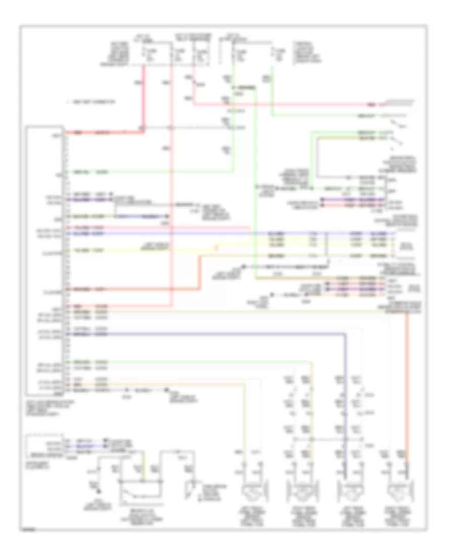
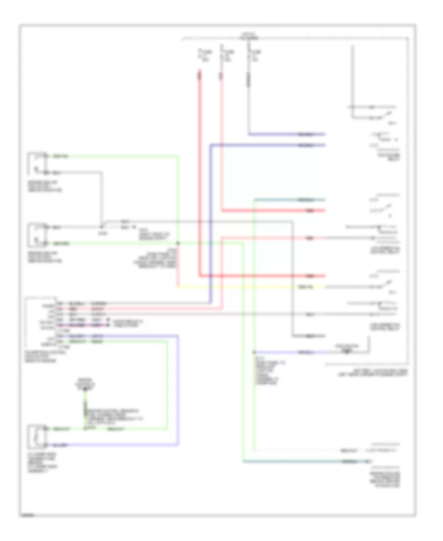
COOLING FAN
Cooling Fan Wiring Diagram for Ford Transit Connect XLT Premium 2013
 https://portal-diagnostov.com/license.html
Automotive Electricians Portal FZCO
Automotive Electricians Portal FZCO
https://portal-diagnostov.com/license.html
https://portal-diagnostov.com/license.html
Automotive Electricians Portal FZCO
Automotive Electricians Portal FZCOList of elements for Cooling Fan Wiring Diagram for Ford Transit Connect XLT Premium 2013:
- (engine control sensor & fuel charge wiring harness, near breakout to coil on plug 3) s124
- 30-pa7
- 31-pa17
- 4-ec7
- 5-ec7
- 91s-rh9
- Battery junction box (bjb) (left rear corner of engine compt)
- C175b
- C175e
- Cht
- Computer data lines system
- Cooling fan diode
- Cylinder head temperature sensor (cylinder head assembly)
- Engine controls system
- Engine cooling fan motor 1 (behind radiator)
- Engine cooling fan motor 2 (behind radiator)
- Engine cooling fan resistor (behind center of radiator)
- Fuse 10a
- Fuse 30a
- Fuse 50a
- G103 (right front of engine compt)
- Hfc
- High speed fan control relay
- Hot at all times
- Hs can+
- Hs can-
- Lfc
- Low speed fan control relay
- Pcm power relay
- Pcmrc
- Powertrain control module (pcm) (rear of engine)
- Re405
- Red
- S106
- S108 (dash panel to headlamp junction wiring harness, near breakout to horn)
- S113 (dash panel to headlamp junction wiring harness, in under bjb)
- Sigrtn
- Ve712
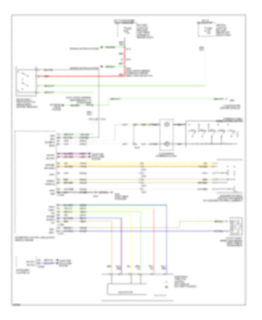
CRUISE CONTROL
Cruise Control Wiring Diagram for Ford Transit Connect XLT Premium 2013
 https://portal-diagnostov.com/license.html
Automotive Electricians Portal FZCO
Automotive Electricians Portal FZCO
https://portal-diagnostov.com/license.html
https://portal-diagnostov.com/license.html
Automotive Electricians Portal FZCO
Automotive Electricians Portal FZCOList of elements for Cruise Control Wiring Diagram for Ford Transit Connect XLT Premium 2013:
- (main wiring harness, near breakout to microphone) s234
- 15s-lg23
- 31-re8
- 4-ec7
- 5-ec7
- 7-rj30
- 7-rj35
- 8-pg13
- 8-rj29
- 8-rj30
- 8-rj35
- 9-pg13
- 9-rj29
- 9-rj30
- 9-rj35
- 91s-pg6
- Accelerator pedal position (app) sensor (on accelerator pedal assembly)
- App1
- App2
- Apprtn
- Apprtn2
- Appvref
- Appvref2
- Battery junction box (bjb) (left rear corner of engine compt)
- Bpp
- Bps
- Brake pedal position switch (brake pedal support bracket)
- C175b
- C175e
- C175t
- C213
- C215
- C220b
- Ce412
- Ce426
- Central junction box (cjb) (behind left side of dash)
- Clockspring (steering column)
- Computer data lines system
- Electronic throttle control (etc) module (on throttle body)
- Engine controls system
- Etcref
- Etcrtn
- Exterior lights system
- Floor shifter (center console)
- Fuse 10a
- Fuse 15a
- G100 (right rear of engine)
- Gnd
- Hot in run or start
- Hot w/ pcm power relay energized
- Hs can +
- Hs can -
- Hs can+
- Hs can-
- Instrument cluster (ic)
- Le134
- Nca
- Off
- Oss +
- Oss -
- Output shaft speed (oss) sensor (right side of transmission)
- Powertrain control module (pcm) (rear of engine)
- Re134
- Red
- Rsm
- S103
- S112
- S236 (main wiring harness, in breakout brake pedal position switch)
- Sccs
- Sccsrtn
- Set+
- Set-
- Solid state
- Steering wheel/ speed control switch
- Tacm+
- Tacm-
- Tp1
- Tp2
- Ve818
- Ve819
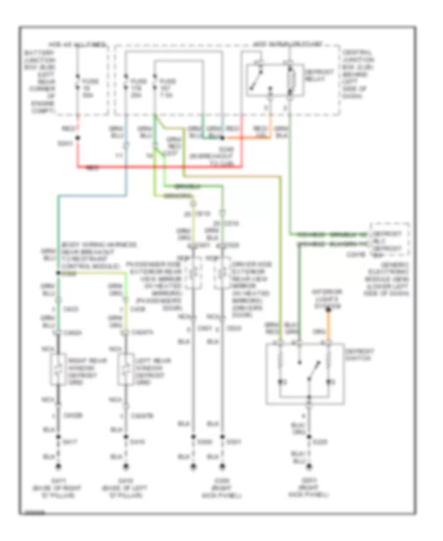
DEFOGGERS
Defoggers Wiring Diagram for Ford Transit Connect XLT Premium 2013
 https://portal-diagnostov.com/license.html
Automotive Electricians Portal FZCO
Automotive Electricians Portal FZCO
https://portal-diagnostov.com/license.html
https://portal-diagnostov.com/license.html
Automotive Electricians Portal FZCO
Automotive Electricians Portal FZCOList of elements for Defoggers Wiring Diagram for Ford Transit Connect XLT Premium 2013:
- (body wiring harness, near breakout to restraint control module) s302
- 15s-hb20
- 31s-hb22
- Battery junction box (bjb) (left rear corner of engine compt)
- C201b
- C237
- C402a
- C402b
- C423
- C4247a
- C4247b
- C438
- C520
- C601
- C610
- Central junction box (cjb) (behind left side of dash)
- Defrost
- Defrost relay
- Defrost switch
- Driver side exterior rear view mirror (w/ heated mirrors) (driver's door)
- Fuse 25a
- Fuse 50a
- Fuse 7.5a
- G203 (right kick panel)
- G300 (right kick panel)
- G410 (base of left "d" pillar)
- G411 (base of right "d" pillar)
- Generic electronic module (gem) (lower left side of dash)
- Hot at all times
- Hot in run or start
- Interior lights system
- Left rear window defrost grid
- Nca
- Passenger side exterior rear view mirror (w/ heated mirrors) (passenger's door)
- Red
- Right rear window defrost grid
- Rlc defrost sw
- S220
- S240 (in breakout to cjb)
- S243
- S410
- S417
- S501
- S600
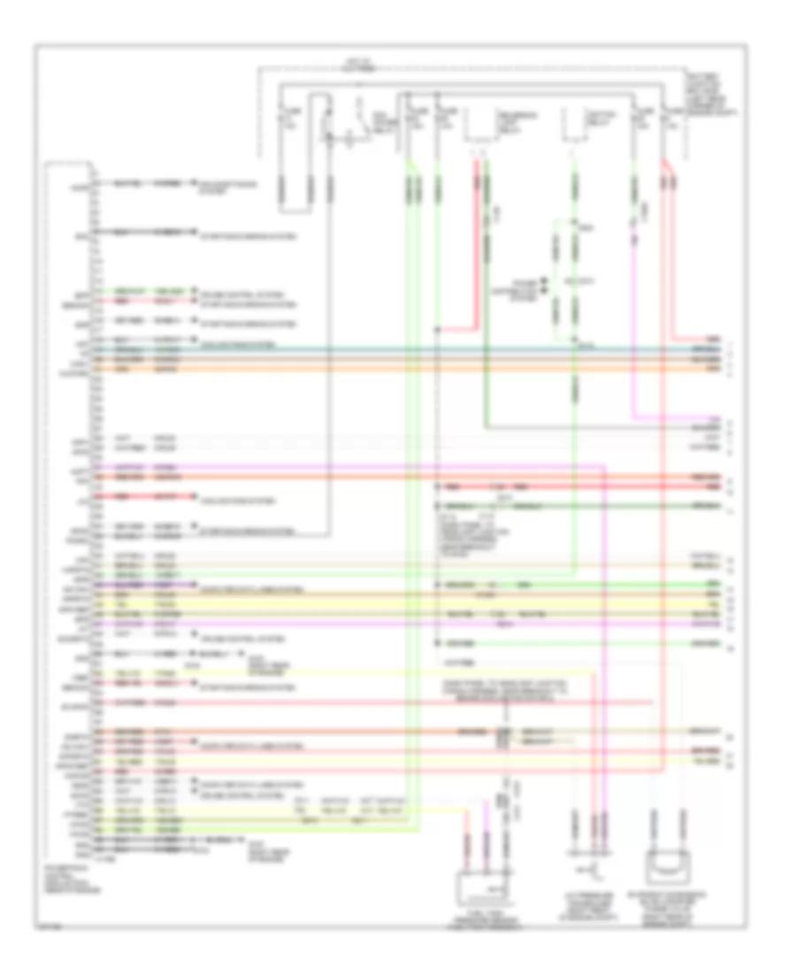
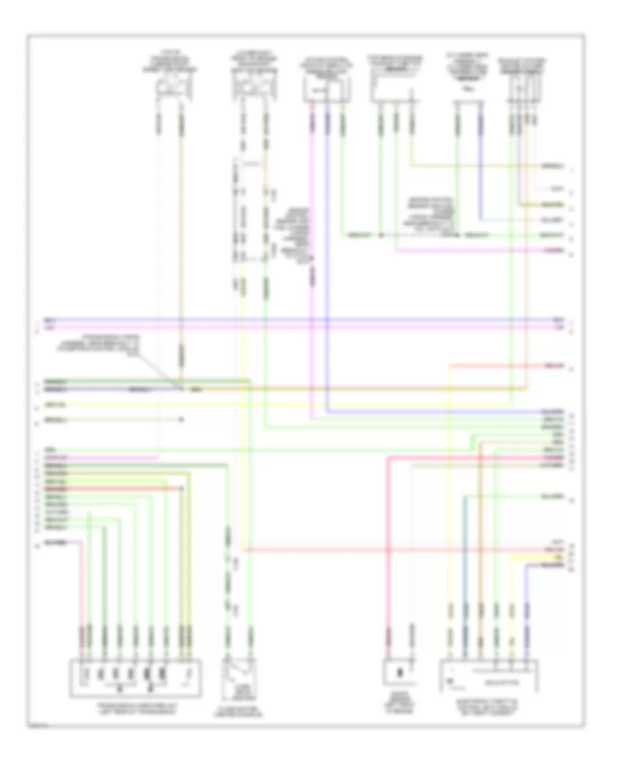
ENGINE PERFORMANCE
2.0L
2.0L, Engine Performance Wiring Diagram (1 of 5) for Ford Transit Connect XLT Premium 2013
 https://portal-diagnostov.com/license.html
Automotive Electricians Portal FZCO
Automotive Electricians Portal FZCO
https://portal-diagnostov.com/license.html
https://portal-diagnostov.com/license.html
Automotive Electricians Portal FZCO
Automotive Electricians Portal FZCOList of elements for 2.0L, Engine Performance Wiring Diagram (1 of 5) for Ford Transit Connect XLT Premium 2013:
- (dash panel to headlamp junction wiring harness, near breakout to engine cooling fan motor 2)
- 15-pc35
- 15-re17
- 15s-lg23
- 15s-re21
- 15s-re8
- 29-rh6
- 30-dj1
- 30-pa7
- 30-re8
- 30s-dj1
- 30s-rh6
- 31-bb16
- 31-pa17
- 31-re21
- 31-re25
- 31-re8
- 4-ec7
- 4-ee14
- 5-ec7
- 50-bb14
- 50-bb15
- 7-fa88
- 7-rj13
- 7-rj30
- 7-rj35
- 8-fa88
- 8-pg13
- 8-rj13
- 8-rj17
- 8-rj22
- 8-rj30
- 8-rj35
- 8-rl25
- 9-fa1
- 9-pg13
- 9-rj22
- 9-rj30
- 9-rj35
- 91s-pg6
- 91s-re8
- 91s-rh9
- 91s-rl3
- A/c pressure transducer (right front of engine compt)
- Accr
- Acpt
- Air conditioning system
- App1
- App2
- App2rtn
- App2vref
- Apprtn
- Appvref
- Battery junction box (bjb) (left rear corner of engine compt)
- Bpp
- Bps
- C1045
- C110
- C175b
- C211
- C213
- Canv
- Computer data lines system
- Cooling fans system
- Cruise control system
- Evapcp
- Evaporative emission (evap) canister purge valve (right rear of engine compt)
- Feps
- Fpm
- Ftp
- Ftpref
- Fuel tank pressure sensor (fuel tank assembly)
- Fuse 10a
- Fuse 15a
- G100 (right rear of engine)
- Gencom
- Genmon
- Gnd
- Hfc
- Hot at all times
- Hs can+
- Hs can-
- Iat
- Ignition relay
- Injpwrm
- Ispr
- Kapwr
- Lfc
- Maf
- Mafrtn
- Pcm power relay
- Pcmrc
- Power distribution system
- Powertrain control module (pcm) (rear of engine)
- Red
- Reversing lamp relay
- S103
- S112 (dash panel to headlamp junction wiring harness, near breakout to g102)
- S118
- S224
- Sccs
- Sccsrtn
- Sigrtn
- Smc
- Smcs
- Smr
- Starting/charging system
- Vpwr
- Vref
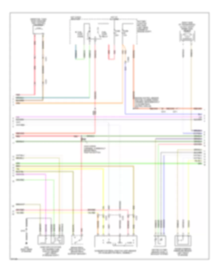
2.0L, Engine Performance Wiring Diagram (2 of 5) for Ford Transit Connect XLT Premium 2013
 https://portal-diagnostov.com/license.html
Automotive Electricians Portal FZCO
Automotive Electricians Portal FZCO
https://portal-diagnostov.com/license.html
https://portal-diagnostov.com/license.html
Automotive Electricians Portal FZCO
Automotive Electricians Portal FZCOList of elements for 2.0L, Engine Performance Wiring Diagram (2 of 5) for Ford Transit Connect XLT Premium 2013:
- (engine control sensor and fuel charge wiring harness, near breakout to powertrain control module) s121
- (main wiring harness, in breakout brake pedal position switch)
- (near fuel tank) evap canister vent control solenoid
- (right side of transmission) output shaft speed (oss) sensor
- Accelerator pedal position (app) sensor (on accelerator pedal assembly)
- Battery junction box (bjb) (left rear corner of engine compt)
- Brake pedal position switch (brake pedal support bracket)
- C1045
- C211
- C213
- C215
- Fuel pump diode
- Fuel pump relay
- Fuse 10a
- Fuse 20a
- G100 (right rear of engine)
- Heated oxygen sensor (ho2s) 12 (exhaust system)
- Hot at all times
- Hot in run or start
- Mass air flow/intake air temperature (maf/iat) sensor (left front of engine compt)
- Power steering pressure sensor (left front of engine)
- Red
- S103
- S236
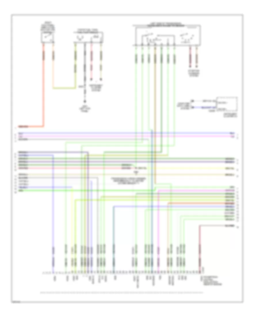
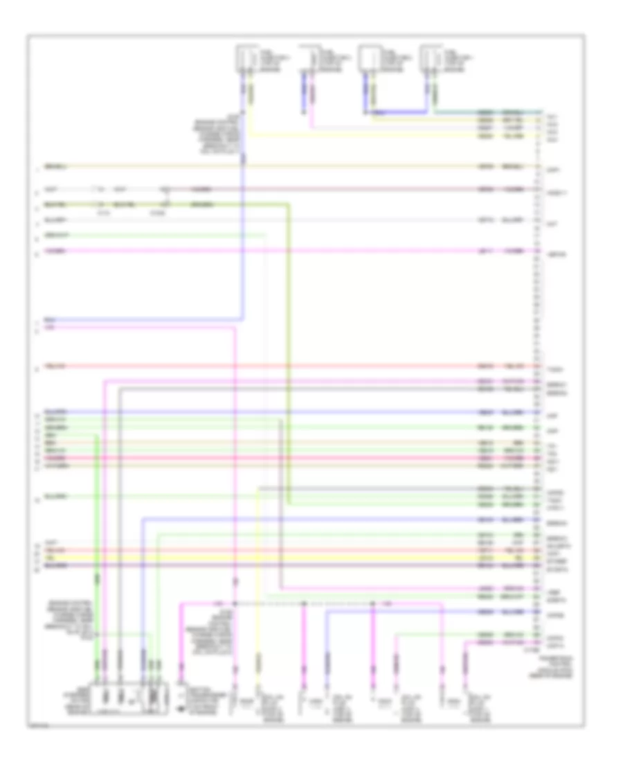
2.0L, Engine Performance Wiring Diagram (3 of 5) for Ford Transit Connect XLT Premium 2013
 https://portal-diagnostov.com/license.html
Automotive Electricians Portal FZCO
Automotive Electricians Portal FZCO
https://portal-diagnostov.com/license.html
https://portal-diagnostov.com/license.html
Automotive Electricians Portal FZCO
Automotive Electricians Portal FZCOList of elements for 2.0L, Engine Performance Wiring Diagram (3 of 5) for Ford Transit Connect XLT Premium 2013:
- (left side of transmission) transmission range (tr) sensor
- (right kick panel) inertia fuel shutoff (ifs) switch
- (top of fuel tank) fuel pump module
- (transmission wiring harness, near breakout to heated oxygen sensor 11)
- 15-ta41
- 15-ta42
- 15s-rg2
- 15s-ta17
- 15s-ta21
- 15s-ta23
- 15s-ta24
- 15s-ta37
- 15s-ta38
- 15s-ta39
- 15s-ta40
- 15s-ta63
- 15s-ta64
- 15s-ta65
- 31-rg2
- 31s-lg45
- 7-ta71
- 8-ga7
- 8-rj25
- 8-rj29
- 8-ta27
- 8-ta36
- 8-ta71
- 9-ga7
- 9-pa1
- 9-rj29
- 91s-rj25
- 91s-ta17
- C175t
- C220b
- Computer data lines system
- Drive
- G301 (left kick panel)
- Ho2s-12
- Hs can +
- Hs can -
- Htr-12
- Instrument cluster (ic)
- Instrument cluster system
- Neutral
- O/d cancel
- Oss+
- Oss-
- Park
- Pca
- Powertrain control module (pcm) (rear of engine)
- Pspt
- Reverse
- Rlc
- S101
- S303
- Sigrtnt
- Ssa
- Ssb
- Ssc
- Ssd
- Sse
- Starting/ charging system
- Tft
- Tspc
- Tss
- Vref
2.0L, Engine Performance Wiring Diagram (4 of 5) for Ford Transit Connect XLT Premium 2013
 https://portal-diagnostov.com/license.html
Automotive Electricians Portal FZCO
Automotive Electricians Portal FZCO
https://portal-diagnostov.com/license.html
https://portal-diagnostov.com/license.html
Automotive Electricians Portal FZCO
Automotive Electricians Portal FZCOList of elements for 2.0L, Engine Performance Wiring Diagram (4 of 5) for Ford Transit Connect XLT Premium 2013:
- (cylinder head assembly) cylinder head temperature sensor
- (engine control sensor and fuel charge wiring harness, near breakout to c1180) s123
- (engine control sensor and fuel charge wiring harness, near breakout to coil on plug 3) s124
- (exhaust system) heated oxygen sensor (ho2s) 11
- (intake system) manifold absolute pressure (map) sensor
- (lower right front of engine) crankshaft position sensor
- (or red)
- (top of transmission) turbine shaft speed (tss) sensor
- (top rear of engine) camshaft position sensor
- (transmission wiring harness, near breakout to powertrain control module) s131
- C1045
- C110
- C215
- Ce412
- Ce426
- Electronic throttle control (etc) module (on throttle body)
- Floor shifter (center console)
- Knock sensor (left front of engine)
- Le134
- Nca
- Over/ drive switch
- Re134
- Solid state
- Ssa
- Ssb
- Ssc
- Ssd
- Sse
- Transmission hardware unit (left rear of transmission)
- Ve818
- Ve819
2.0L, Engine Performance Wiring Diagram (5 of 5) for Ford Transit Connect XLT Premium 2013
 https://portal-diagnostov.com/license.html
Automotive Electricians Portal FZCO
Automotive Electricians Portal FZCO
https://portal-diagnostov.com/license.html
https://portal-diagnostov.com/license.html
Automotive Electricians Portal FZCO
Automotive Electricians Portal FZCOList of elements for 2.0L, Engine Performance Wiring Diagram (5 of 5) for Ford Transit Connect XLT Premium 2013:
- (engine control sensor and fuel charge wiring harness, near breakout to coil on plug 4) s122
- C1045
- C110
- C175e
- Ce101
- Ce102
- Ce103
- Ce104
- Ce205
- Ce206
- Ce207
- Ce208
- Ce235
- Ce303
- Ce304
- Ce305
- Ce306
- Ce412
- Ce426
- Cht
- Ckp+
- Ckp-
- Cmp1
- Coil 1
- Coil 2
- Coil 3
- Coil 4
- Coil on plug (cop) 1 (top of engine)
- Coil on plug (cop) 2 (top of engine)
- Coil on plug (cop) 3 (top of engine)
- Coil on plug (cop) 4 (top of engine)
- Cop1a
- Cop2d
- Cop3b
- Cop4c
- De135
- Egr stepper motor (rear of engine)
- Egrmc1
- Egrmc2
- Egrmc3
- Egrmc4
- Etcref
- Etcrtn
- Fuel injector 1 (top of engine)
- Fuel injector 2 (top of engine)
- Fuel injector 3 (top of engine)
- Fuel injector 4 (top of engine)
- Ho2s-11
- Htr-11
- Ignition transformer capacitor (top front of engine)
- Inj1
- Inj2
- Inj3
- Inj4
- Ks1+
- Ks1-
- Le111
- Le134
- Le423
- Map
- Powertrain control module (pcm) (rear of engine)
- Re134
- Re135
- Re323
- Re405
- S126 (engine control sensor and fuel charge wiring harness, near breakout to coil on plug 2)
- Shldrtn
- Sigrtn
- Tacm+
- Tacm-
- Tp1
- Tp2
- Vbpwr
- Ve706
- Ve711
- Ve712
- Ve735
- Ve801
- Ve803
- Ve818
- Ve819
- Vref
EXTERIOR LIGHTS
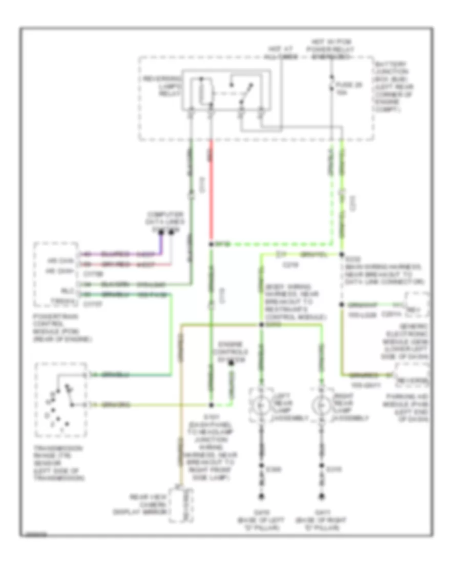
Backup Lamps Wiring Diagram for Ford Transit Connect XLT Premium 2013
 https://portal-diagnostov.com/license.html
Automotive Electricians Portal FZCO
Automotive Electricians Portal FZCO
https://portal-diagnostov.com/license.html
https://portal-diagnostov.com/license.html
Automotive Electricians Portal FZCO
Automotive Electricians Portal FZCOList of elements for Backup Lamps Wiring Diagram for Ford Transit Connect XLT Premium 2013:
- (body wiring harness, near breakout to restraints control module) s313
- 15s-gn11
- 15s-lg28
- 15s-ta38
- 31s-lg45
- 4-ec7
- 5-ec7
- Battery junction box (bjb) (left rear corner of engine compt)
- C110
- C175b
- C175t
- C215
- C219
- Computer data lines system
- Engine controls system
- Fuse 26 10a
- G410 (base of left "d" pillar)
- G411 (base of right "d" pillar)
- Generic electronic module (gem) (lower left side of dash)
- Hot at all times
- Hot w/ pcm power relay energized
- Hs can+
- Hs can-
- Left rear lamp assembly
- Parking aid module (pam) (left end of dash)
- Powertrain control module (pcm) (rear of engine)
- Rear view camera display mirror
- Red
- Rev c201a
- Reverse
- Reversing lamps relay
- Right rear lamp assembly
- Rlc
- S101 (dash panel to headlamp junction wiring harness, near breakout to right front side lamp)
- S112
- S232 (main wiring harness, near breakout to data link connector)
- S300
- S315
- Transmission range (tr) sensor (left side of transmission)
- Trsw4
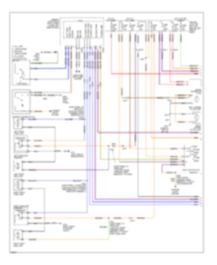
Exterior Lamps Wiring Diagram (1 of 2) for Ford Transit Connect XLT Premium 2013
 https://portal-diagnostov.com/license.html
Automotive Electricians Portal FZCO
Automotive Electricians Portal FZCO
https://portal-diagnostov.com/license.html
https://portal-diagnostov.com/license.html
Automotive Electricians Portal FZCO
Automotive Electricians Portal FZCOList of elements for Exterior Lamps Wiring Diagram (1 of 2) for Ford Transit Connect XLT Premium 2013:
- (dash panel to headlamp junction wiring harness, near breakout to g103) s122
- (dash panel to headlamp junction wiring harness, near breakout to horn)
- (taxi) 10a
- 15a
- 29s-lf25
- 4-ec14
- 49s-lg1
- 49s-lg12
- 49s-lg18
- 49s-lg19
- 49s-lg2
- 49s-lg5
- 5-ec14
- 91s-lg8
- Block connector (taxi)
- C201b
- C201e
- C215
- C219
- C438
- Central junction box (cjb) (behind left side of dash)
- Computer data lines system
- Full left
- Full right
- Fuse
- Fuse (taxi) 10a
- Fuse (taxi) 15a
- Fuse 10a
- Fuse 7.5a
- G101 (left side of engine compt)
- G103 (right front of engine compt)
- G203 (right kick panel)
- G410 (base of left "d" pillar)
- Generic electronic module (gem) (lower left side of dash)
- Hazard
- Hazard flasher switch
- Head
- Hot at all times
- Hot in start or run
- Interior lights system
- Lane change
- Left front side lamp
- Left front turn lamp
- Left headlamp assembly
- Left license plate lamp
- Left turn
- Lh front turn
- Lh rear turn
- License lamp
- Logic
- Main light switch
- Ms can+
- Ms can-
- Multi-function switch
- Neutral
- Off
- Park
- Park/turn
- Red
- Rh front turn
- Rh rear turn
- Right front side lamp
- Right front turn lamp
- Right headlamp assembly
- Right license plate lamp
- Right turn
- S100 (dash panel to headlamp junction wiring harness, near breakout to right front side lamp)
- S102
- S106
- S109
- S151 (dash panel to headlamp junction wiring harness, near breakout to right headlamp assembly)
- S220
- S241
- S410
- Turn signal
Exterior Lamps Wiring Diagram (2 of 2) for Ford Transit Connect XLT Premium 2013
 https://portal-diagnostov.com/license.html
Automotive Electricians Portal FZCO
Automotive Electricians Portal FZCO
https://portal-diagnostov.com/license.html
https://portal-diagnostov.com/license.html
Automotive Electricians Portal FZCO
Automotive Electricians Portal FZCOList of elements for Exterior Lamps Wiring Diagram (2 of 2) for Ford Transit Connect XLT Premium 2013:
- (brake pedal support bracket) brake pedal position switch
- (main wiring harness, near breakout to microphone) s234
- (not used)
- (taxi) left turn relay
- (taxi) right turn relay
- 15s-lg23
- 4-ec7
- 5-ec7
- 91s-pg6
- Battery junction box (bjb) (left rear corner of engine compt)
- Bpp
- Bps
- C175b
- C211
- C213
- C215
- C219
- C220b
- C406
- C432
- Computer data lines system
- Floor shifter (center console)
- Fuse (taxi) 25a
- Fuse 10a
- G101 (left side of engine compt)
- G200 (left kick panel)
- G410 (base of left "d" pillar)
- G411 (base of right "d" pillar)
- High mounted stoplamp
- Hot at all times
- Hot w/ pcm power relay energized
- Hs can+
- Hs can-
- Instrument cluster (ic)
- Left rear lamp assembly
- Left rear marker lamp
- Powertrain control module (pcm) (rear of engine)
- Red
- Right rear lamp assembly
- Right rear marker lamp
- S115
- S154
- S228
- S236
- S300
- S306 (body wiring harness, near breakout to restraints control module)
- S315
- S420
- Stop/park
- Taxi roof lamp (taxi)
- Taxi roof lamp switch (taxi)
- Turn
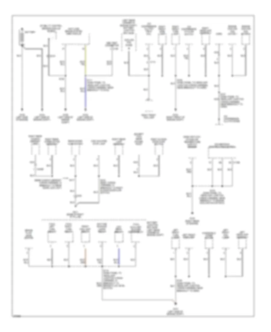
GROUND DISTRIBUTION
Ground Distribution Wiring Diagram (1 of 3) for Ford Transit Connect XLT Premium 2013
 https://portal-diagnostov.com/license.html
Automotive Electricians Portal FZCO
Automotive Electricians Portal FZCO
https://portal-diagnostov.com/license.html
https://portal-diagnostov.com/license.html
Automotive Electricians Portal FZCO
Automotive Electricians Portal FZCOList of elements for Ground Distribution Wiring Diagram (1 of 3) for Ford Transit Connect XLT Premium 2013:
- (except taxi) rear power point
- (left rear corner of engine compt) battery junction box (bjb)
- (rear window defrost wiring harness, in breakout to rear door lock unit)
- (taxi) auxiliary blower motor relay
- (taxi) left turn relay
- (taxi) right turn relay
- A/c compressor clutch diode
- A/c compressor clutch field coil
- A/c compressor cycling switch
- Abs test connector
- Anti-lock brake system (abs) module
- Battery
- Battery junction box (bjb) (left rear corner of engine compt)
- Brake fluid level switch
- Brake fluid level switch)
- C110
- C126
- C175b
- C215
- C402b
- C423
- Cooling fan diode
- Daytime running lamps relay
- Engine cooling fan motor 1
- Engine cooling fan motor 2
- Front fog lamp relay
- G100 (right rear of engine)
- G101 (left side of engine compt)
- G102 (left side of engine compt)
- G103 (right front of engine compt)
- G104 (left side of engine compt)
- G105 (left side of engine)
- G106 (left side of engine compt)
- G411 (base of right "d" pillar)
- High mounted stop lamp
- Horn
- Left front fog lamp
- Left front side lamp
- Left front turn lamp
- Left headlamp assembly
- Low beam relay
- Mass air flow/ intake air temperature (maf/iat) sensor
- Nca
- Powertrain control module (pcm)
- Rear doors ajar switch
- Right front fog lamp
- Right front side lamp
- Right front turn lamp
- Right headlamp assembly
- Right rear lamp assembly
- Right rear window defrost grid
- Right rear wiper motor assembly
- Right sliding door ajar switch
- S103 (dash panel to headlamp junction wiring harness, near breakout to engine cooling fan motor 2)
- S127 (dash panel to headlamp junction nca
- S152
- S315 (body wiring harness, in breakout to right sliding door ajar switch)
- S417
- Stability control sensor module shield
- Windshield wiper motor
- Wiring harness, near breakout to horn)
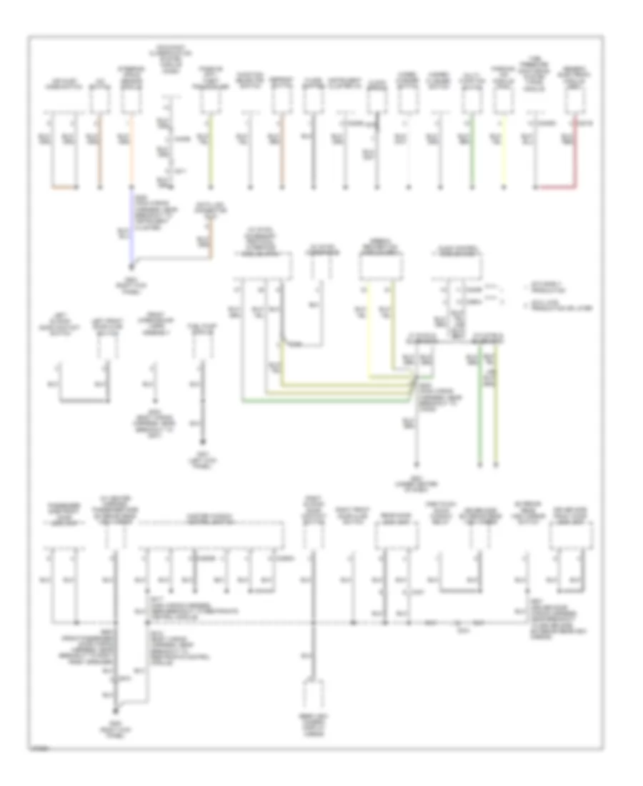
Ground Distribution Wiring Diagram (2 of 3) for Ford Transit Connect XLT Premium 2013
 https://portal-diagnostov.com/license.html
Automotive Electricians Portal FZCO
Automotive Electricians Portal FZCO
https://portal-diagnostov.com/license.html
https://portal-diagnostov.com/license.html
Automotive Electricians Portal FZCO
Automotive Electricians Portal FZCOList of elements for Ground Distribution Wiring Diagram (2 of 3) for Ford Transit Connect XLT Premium 2013:
- (w/ heated mirrors) passenger side exterior rear view mirror
- (w/ sync) accessory protocol interface module (apim)
- (w/ sync) microphone
- 2012 early production
- 2012 late production or later
- A/c switch
- Air inlet mode switch
- Audio control module (acm)
- C201b
- C211
- C220b
- C2409a
- C240b
- C248
- C290a
- C3293a
- C3293b
- C340b
- C421
- C510
- C610
- Clock spring
- Control module)
- Data link connector (dlc)
- Defrost switch
- Driver side exterior rear view mirror
- Driver side front door lock unit
- Exterior rear view mirror switch
- Floor shifter
- Front interior/map lamps assembly
- Fuel pump module
- Function selector switch
- G201 (under center of dash)
- G203 (right kick panel)
- G300 (right kick panel)
- G301 (left kick panel)
- Generic electronic module (gem)
- Hazard flasher switch
- Instrument cluster (ic)
- Left front door ajar switch
- Left sliding door contact switch
- Master window control switch
- Multi- function switch
- Nca
- Occupant classification system module (ocsm)
- One-touch down window relay
- Parking aid module (pam)
- Passenger side front door lock unit
- Passive anti- theft transceiver
- Rear door lock unit
- Rear view camera display mirror
- Right front door ajar switch
- Right sliding door contact switch
- S203 (main wiring harness, near breakout to c3249)
- S220 (main wiring harness, near breakout to instrument cluster)
- S303 (body wiring harness, near breakout to g301)
- S312 (body wiring harness, near breakout to restraints control module)
- S501 (driver door wiring harness, near breakout to driver side exterior rearview mirror)
- S600 (front passenger door wiring harness, near breakout to right front speaker)
- Speech recognition module (srm)
- Steering angle sensor module
- Tire pressure monitoring system (tpms) module
- Wiper/ washer switch
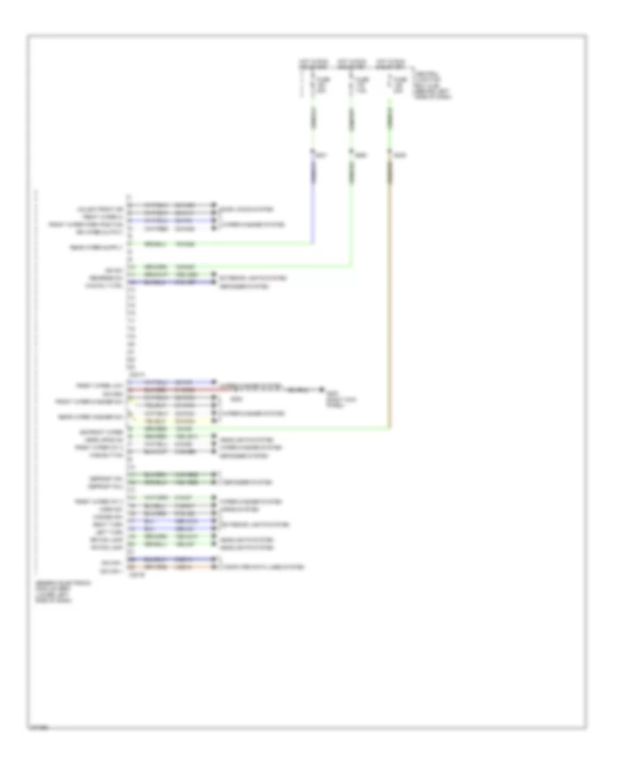
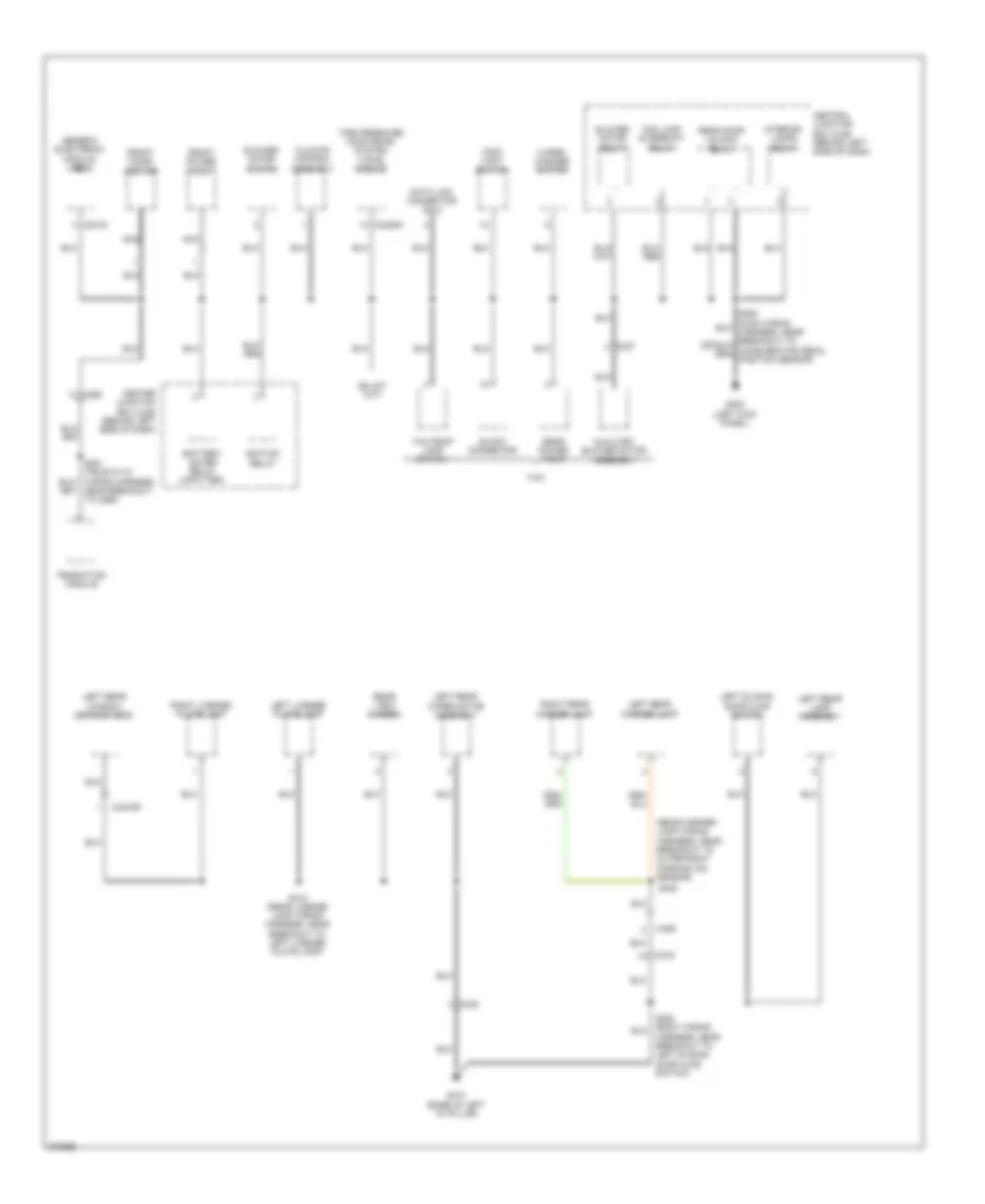
Ground Distribution Wiring Diagram (3 of 3) for Ford Transit Connect XLT Premium 2013
 https://portal-diagnostov.com/license.html
Automotive Electricians Portal FZCO
Automotive Electricians Portal FZCO
https://portal-diagnostov.com/license.html
https://portal-diagnostov.com/license.html
Automotive Electricians Portal FZCO
Automotive Electricians Portal FZCOList of elements for Ground Distribution Wiring Diagram (3 of 3) for Ford Transit Connect XLT Premium 2013:
- (rear marker lamp wiring harness, near breakout to outer right parking aid sensor)
- Auxiliary blower motor assembly
- Battery saver relay (upfitter)
- Block connector
- Blower motor relay
- Blower motor switch
- C201d
- C2409a
- C268
- C327
- C406
- C4247b
- C432
- C438
- Center junction box (cjb) (behind left side of dash)
- Central junction box (cjb) (behind left side of dash)
- Climate control assembly
- Data link connector (dlc)
- Fog lamp interrupt relay
- Front cigar lighter
- Front power point
- G200 (left kick panel)
- G410 (base of left "d" pillar)
- Generic electronic module (gem)
- Ignition relay
- Interior lamps relay
- Left license plate lamp
- Left rear lamp assembly
- Left rear marker lamp
- Left rear window defrost grid
- Left rear wiper motor assembly
- Left sliding door ajar switch
- Main light switch
- Nca
- Near breakout to c268)
- Rear door unlock relay
- Rear power point
- Rear view camera
- Right license plate lamp
- Right rear marker lamp
- S300 (body wiring harness, near breakout to left sliding door ajar switch)
- S410 (rear license lamp wiring harness, near breakout to left license plate lamp)
- S420
- Taxi
- Taxi roof lamp switch
- Telematics module
- Tire pressure monitoring system (tpms) module
- Wiper/ washer switch
HEADLIGHTS
Headlights Wiring Diagram (1 of 2) for Ford Transit Connect XLT Premium 2013
 https://portal-diagnostov.com/license.html
Automotive Electricians Portal FZCO
Automotive Electricians Portal FZCO
https://portal-diagnostov.com/license.html
https://portal-diagnostov.com/license.html
Automotive Electricians Portal FZCO
Automotive Electricians Portal FZCOList of elements for Headlights Wiring Diagram (1 of 2) for Ford Transit Connect XLT Premium 2013:
- (left rear corner of engine compt) battery junction box (bjb)
- (main wiring harness, near breakout to instrument cluster) s207
- 15s-ld13
- 15s-ld7
- 15s-le14
- 29s-lf25
- 4-ec14
- 5-ec14
- C201b
- C201e
- C213
- C215
- Central junction box (cjb) (behind left side of dash)
- Computer data lines system
- Early production
- Exterior lights system
- Fog lamp interrupt relay
- Fog lamps
- Front fog
- Front fog ind
- Front fog lamp relay
- Frt fog lps
- Fuse 10a
- Fuse 15a
- Fuse 7.5a
- G101 (left side of engine compt)
- G103 (right front of engine compt)
- G200 (left kick panel)
- Generic electronic module (gem) (lower left side of dash)
- Hdlps on
- Head
- Headlamp
- Hot at all times
- Hot in run or start
- Hot w/ ignition relay energized
- Interior lights system
- Late production
- Left headlamp assembly
- License lamp
- Low beam interrupt relay
- Main light switch
- Ms can+
- Ms can-
- Off
- Park
- Rear fog
- Rear fog ind
- Red
- Right headlamp assembly
- S105 (dash panel to headlamp junction wiring harness, near breakout to engine cooling fan motor 2)
- S106
- S109
- S115
- S204 (w/ front fog lamps)
- S218 (main wiring harness, near breakout to audio control module)
- S228
- S230 (main wiring harness, in breakout to main light switch)
- S260
Headlights Wiring Diagram (2 of 2) for Ford Transit Connect XLT Premium 2013
 https://portal-diagnostov.com/license.html
Automotive Electricians Portal FZCO
Automotive Electricians Portal FZCO
https://portal-diagnostov.com/license.html
https://portal-diagnostov.com/license.html
Automotive Electricians Portal FZCO
Automotive Electricians Portal FZCOList of elements for Headlights Wiring Diagram (2 of 2) for Ford Transit Connect XLT Premium 2013:
- (dash panel to headlamp junction
- Acc
- Battery junction box (bjb) (left rear corner of engine compt)
- Brake fluid level switch (on master cylinder reservoir)
- Brk warning
- C213
- C215
- C219
- C220a
- C220b
- Computer data lines system
- Daytime running lamps relay
- Drl resistor wire
- Flash to pass
- Ftp
- Fuse 10a
- Fuse 15a
- Fuse 25a
- G101 (left side of engine compt)
- G103 (right front of engine compt)
- G203 (right kick panel)
- G410 (base of left "d" pillar)
- G411 (base of right "d" pillar)
- Hi beam
- Hi beam rly
- High
- High beam relay
- Hot at all times
- Ignition switch
- Instrument cluster
- Left front fog lamp
- Left rear fog lamp
- Lo beam int rly
- Lo beam sw
- Low beam relay
- Ms can+
- Ms can-
- Multi-function switch
- Off
- Park brake switch (center console)
- Red
- Right front fog lamp
- Right rear fog lamp
- Run
- S106
- S109
- S115
- S118
- S119
- S220
- S244
- S300
- S315
- Start
- Wiring harness, in under bjb)
HORN
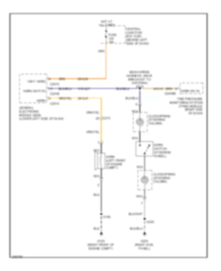
Horn Wiring Diagram for Ford Transit Connect XLT Premium 2013
 https://portal-diagnostov.com/license.html
Automotive Electricians Portal FZCO
Automotive Electricians Portal FZCO
https://portal-diagnostov.com/license.html
https://portal-diagnostov.com/license.html
Automotive Electricians Portal FZCO
Automotive Electricians Portal FZCOList of elements for Horn Wiring Diagram for Ford Transit Connect XLT Premium 2013:
- (main wiring harness, near breakout to antenna) s233
- 29-gj6
- 29-gj8
- 31s-gj7
- 9-wa6
- C201b
- C201c
- C213
- C2409b
- Central junction box (cjb) (behind left side of dash)
- Clockspring (steering column)
- Fuse 15a
- G103 (right front of engine compt)
- G203 (right kick panel)
- General electronic module (gem) (lower left side of dash)
- Horn
- Horn (left front of engine compt)
- Horn sw in
- Horn switch
- Horn switch (steering wheel)
- Hot at all times
- Nca
- S106
- S220
- Tire pressure monitoring system (tpms) module (right end of dash)
- Vbat horn
INSTRUMENT CLUSTER
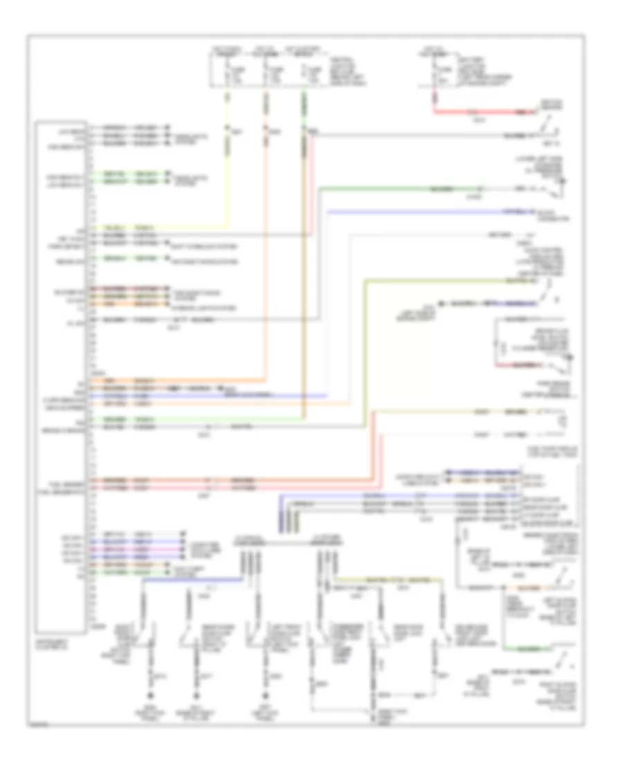
Instrument Cluster Wiring Diagram for Ford Transit Connect XLT Premium 2013
 https://portal-diagnostov.com/license.html
Automotive Electricians Portal FZCO
Automotive Electricians Portal FZCO
https://portal-diagnostov.com/license.html
https://portal-diagnostov.com/license.html
Automotive Electricians Portal FZCO
Automotive Electricians Portal FZCOList of elements for Instrument Cluster Wiring Diagram for Ford Transit Connect XLT Premium 2013:
- (base of left "d" pillar) g410
- (lower left side of engine) oil pressure switch
- (right kick panel) g300
- 10-gl37
- 15-gg14
- 15s-fa13
- 15s-fa90
- 15s-le12
- 15s-le21
- 15s-le36
- 29-gg14
- 29s-gg14
- 31s-aa17
- 31s-fa26
- 31s-gc21
- 31s-gc6
- 31s-gl16
- 31s-gl20
- 31s-gl9
- 31s-ta31
- 31s-ta32
- 4-ec13
- 4-ec14
- 4-ec8
- 4-gb10
- 5-ec13
- 5-ec14
- 5-ec8
- 75-gg14
- 8-ga7
- 8-gl37
- 8-nc8
- 9-ga7
- 91-gg14
- 91s-le14
- 91s-le25
- A/c sw
- A/r
- Air conditioning system
- Anti-theft system
- Audio control module (acm) (late production w/ premium) (center of dash)
- Battery junction box (bjb) (left rear corner of engine compt)
- Block connector
- Blower on
- Brake fluid level switch (on master cylinder reservoir)
- Brake warning
- C1045
- C201b
- C201e
- C211
- C213
- C219
- C220a
- C220b
- C237
- C290a
- C421
- C423
- C510
- C610
- Central junction box (cjb) (behind left side of dash)
- Computer data lines system
- Driver side front door lock unit (driver's door)
- Ftp
- Fuel pump module (top of fuel tank)
- Fuel sender
- Fuel sender rtn
- Fuse 20a
- Fuse 7.5a
- G101 (left side of engine compt)
- G203 (right kick panel)
- G300 (right kick panel)
- G301 (left kick panel)
- G411 (base of right "d" pillar)
- Generic electronic module (gem) (lower left side of dash)
- Gnd
- Headlights system
- High beam rly
- High beam sw
- Hot at all times
- Hot in run or acc
- Hot in start or run
- Hs can +
- Hs can -
- Ic spd sens sig
- Ignition switch
- Ill
- Instrument cluster (ic)
- Interior lights system
- Key in
- Key in sw
- Left front door ajar switch (left kick panel)
- Left sliding door ajar switch (base of left "c" pillar)
- Lf door ajar
- Low beam
- Low beam rly
- Ms can +
- Ms can -
- Oil sw
- Park brake switch (center console)
- Park detect
- Passenger side front door lock unit (passe- nger's door)
- R/s
- Rear door ajar
- Rear door door lock unit
- Rear doors door ajar switch (right "d" pillar)
- Recirc sw
- Red
- Rf door ajar
- Right front door ajar switch (right kick panel)
- Right sliding door ajar switch (base of right "c" pillar)
- S115
- S220
- S221
- S235
- S260
- S300
- S303
- S309 (near breakout to c219)
- S312
- S315
- S417
- S501
- S600
- Shift interlock system
- Sliding door ajar
- Vechile speed
- W/ manual door locks
- W/ power door locks
INTERIOR LIGHTS
Courtesy Lamps Wiring Diagram for Ford Transit Connect XLT Premium 2013
 https://portal-diagnostov.com/license.html
Automotive Electricians Portal FZCO
Automotive Electricians Portal FZCO
https://portal-diagnostov.com/license.html
https://portal-diagnostov.com/license.html
Automotive Electricians Portal FZCO
Automotive Electricians Portal FZCOList of elements for Courtesy Lamps Wiring Diagram for Ford Transit Connect XLT Premium 2013:
- (base of left "d" pillar) g410
- (body wiring harness, near breakout to c219)
- (body wiring harness, near breakout to c391a) s314
- 29-gj8
- 29-lc7
- 31s-aa17
- 31s-gl16
- 31s-gl20
- 31s-gl9
- 31s-lc18
- Batt saver out
- C201c
- C201d
- C201e
- C211
- C219
- C421
- C423
- C510
- C610
- C901a
- C901b
- C931a
- C931b
- C931c
- C932a
- C932b
- Central junction box (cjb) (behind left side of dash)
- Courtesy
- Driver side door lock unit (driver's door)
- Front interior/ map lamps assembly
- Fuse 15a
- Fuse 7.5a
- G200 (left kick panel)
- G300 (right kick panel)
- G301 (left kick panel)
- G411 (base of right "d" pillar)
- Generic electronic module (gem) (lower left side of dash)
- Hot at all times
- Int lamps relay
- Interior lamps relay
- Left front door ajar switch (left kick panel)
- Left sliding door ajar switch (base of left "c" pillar)
- Lf dr ajar
- Off
- Passenger side door lock unit (passenger's door)
- Rear door door lock unit (right rear door)
- Rear doors door ajar switch (right "d" pillar)
- Rear dr ajar
- Rear interior lamps 1
- Rear interior lamps 2
- Rf dr ajar
- Right front door ajar switch (right kick panel)
- Right sliding door ajar switch (base of right "c" pillar)
- S228
- S300
- S303
- S309
- S312
- S315
- S417
- S501
- S600
- Sliding dr ajar
- W/ manual door locks
- W/ power door locks
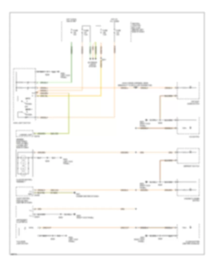
Instrument Illumination Wiring Diagram for Ford Transit Connect XLT Premium 2013
 https://portal-diagnostov.com/license.html
Automotive Electricians Portal FZCO
Automotive Electricians Portal FZCO
https://portal-diagnostov.com/license.html
https://portal-diagnostov.com/license.html
Automotive Electricians Portal FZCO
Automotive Electricians Portal FZCOList of elements for Instrument Illumination Wiring Diagram for Ford Transit Connect XLT Premium 2013:
- (main wiring harness, near breakout to data link connector) s229
- 29s-lf25
- 29s-lk34
- 91-md34
- A/c switch
- Air inlet mode switch
- Audio control module (acm) (center of dash)
- C201e
- C220a
- C240b
- Central junction box (cjb) (behind left side of dash)
- Climate control assembly
- Defrost switch
- Exterior lights system
- Floor shifter (center console)
- Fuse 10a
- Fuse 7.5a
- G200 (left kick panel)
- G201 (under center of dash)
- G203 (right kick panel)
- Generic electronic module (gem) (lower left side of dash)
- Gnd
- Hazard flasher switch
- Head
- Hot at all times
- Hot in run and start
- Ill
- Instrument cluster (ic)
- License lamp
- Main light switch
- Off
- Park
- S220
- S228
- S241
- Taxi roof lamp switch
NAVIGATION
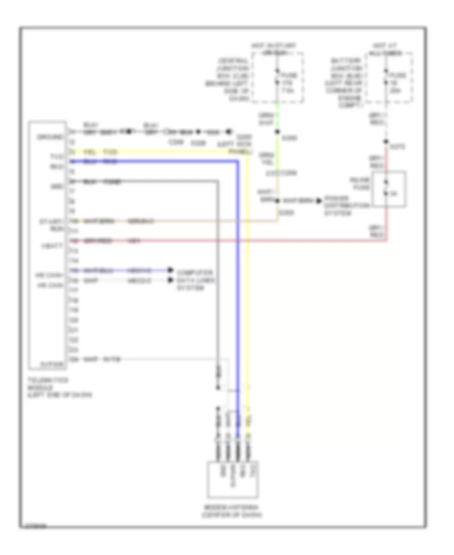
Crew Chief Wiring Diagram for Ford Transit Connect XLT Premium 2013
 https://portal-diagnostov.com/license.html
Automotive Electricians Portal FZCO
Automotive Electricians Portal FZCO
https://portal-diagnostov.com/license.html
https://portal-diagnostov.com/license.html
Automotive Electricians Portal FZCO
Automotive Electricians Portal FZCOList of elements for Crew Chief Wiring Diagram for Ford Transit Connect XLT Premium 2013:
- 5vpwr
- 5vtb
- Battery junction box (bjb) (left rear corner of engine compt)
- C268
- Central junction box (cjb) (behind left side of dash)
- Cgnd
- Computer data lines system
- Fuse 20a
- Fuse 7.5a
- G200 (left kick panel)
- Gnd
- Gnd1
- Ground
- Hot at all times
- Hot in start or run
- Hs can+
- Hs can-
- Hsc1-c
- Hsc2-c
- Igrun-c
- Inline fuse
- Modem antenna (center of dash)
- Nca
- Nca 5vpwr
- Nca gnd
- Nca rxd
- Power distribution system
- Rxd
- S228
- S250
- S251
- S260
- S272
- Start/ run
- Telematics module (left end of dash)
- Txd
- Vb1
- Vbatt
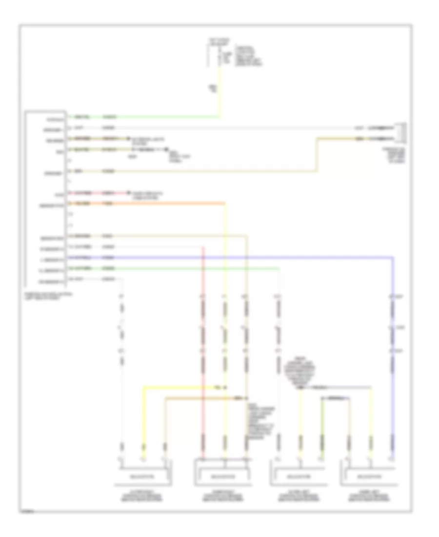
Parking Assistant Wiring Diagram for Ford Transit Connect XLT Premium 2013
 https://portal-diagnostov.com/license.html
Automotive Electricians Portal FZCO
Automotive Electricians Portal FZCO
https://portal-diagnostov.com/license.html
https://portal-diagnostov.com/license.html
Automotive Electricians Portal FZCO
Automotive Electricians Portal FZCOList of elements for Parking Assistant Wiring Diagram for Ford Transit Connect XLT Premium 2013:
- (rear marker lamp wiring harness, near breakout to outer right parking aid sensor) s409
- 15-gn10
- 15s-gn11
- 7-gn2
- 8-ee13
- 8-gn19
- 8-gn20
- 8-gn21
- 8-gn22
- 8-gn26
- 9-gn26
- 9-gn3
- 91-gn10
- C237
- C431
- C432
- Central junction box (cjb) (behind left side of dash)
- Computer data lines system
- Diag
- Exterior lights system
- Fuse 7.5a
- G203 (right kick panel)
- Gnd
- Hot in run or start
- Il sensor in
- Inner left parking aid sensor (behind rear bumper)
- Inner right parking aid sensor (behind rear bumper)
- Ir sensor in
- Nca
- Ol sensor in
- Or sensor in
- Outer left parking aid sensor (behind rear bumper)
- Outer right parking aid sensor (behind rear bumper)
- Parking aid module (pam) (left end of dash)
- Parking aid speaker (left end of dash)
- Pwr run
- Reverse
- S220
- S403 (rear marker lamp wiring harness, near breakout to outer right parking aid sensor)
- Sensor gnd
- Sensor pwr
- Solid state
- Speaker +
- Speaker -
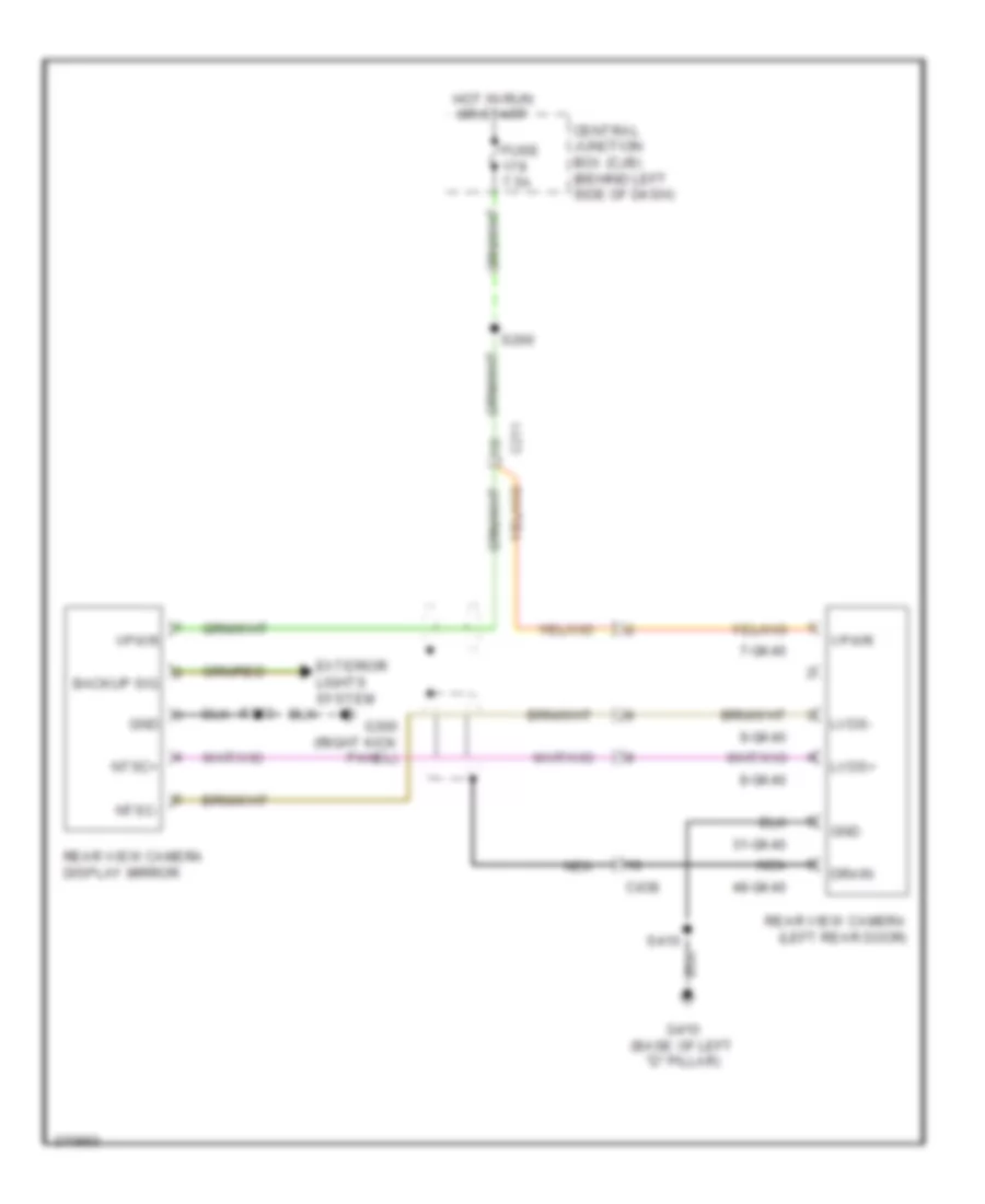
Rear Camera Wiring Diagram for Ford Transit Connect XLT Premium 2013
 https://portal-diagnostov.com/license.html
Automotive Electricians Portal FZCO
Automotive Electricians Portal FZCO
https://portal-diagnostov.com/license.html
https://portal-diagnostov.com/license.html
Automotive Electricians Portal FZCO
Automotive Electricians Portal FZCOList of elements for Rear Camera Wiring Diagram for Ford Transit Connect XLT Premium 2013:
- 31-gk40
- 48-gk40
- 7-gk40
- 8-gk40
- 9-gk40
- Backup sig
- C211
- C438
- Central junction box (cjb) (behind left side of dash)
- Drain
- Exterior lights system
- Fuse 7.5a
- G300 (right kick panel)
- G410 (base of left "d" pillar)
- Gnd
- Hot in run or start
- Lvds+
- Lvds-
- Nca
- Ntsc+
- Ntsc-
- Rear view camera (left rear door)
- Rear view camera display mirror
- S260
- Vpwr
POWER DISTRIBUTION
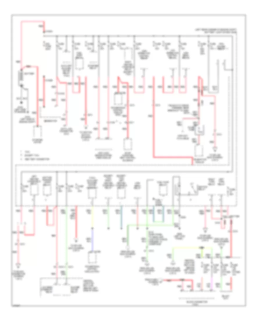
Power Distribution Wiring Diagram (1 of 3) for Ford Transit Connect XLT Premium 2013
 https://portal-diagnostov.com/license.html
Automotive Electricians Portal FZCO
Automotive Electricians Portal FZCO
https://portal-diagnostov.com/license.html
https://portal-diagnostov.com/license.html
Automotive Electricians Portal FZCO
Automotive Electricians Portal FZCOList of elements for Power Distribution Wiring Diagram (1 of 3) for Ford Transit Connect XLT Premium 2013:
- (except taxi) left heated winshield relay
- (except taxi) right heated winshield relay
- (info not available)
- (left rear corner of engine compt) battery junction box (bjb)
- (taxi)
- (taxi) auxiliary blower motor assembly
- (tbj2010-tc wiring harness, near breakout to c268) s272
- 1 of 3)
- Abs test connector
- Anti-lock brake system (abs) module
- Auxiliary blower motor relay (taxi)
- Battery
- Block connector
- Blower motor relay
- C1035a
- C1035b
- C1045
- C126
- C175b
- C211
- C213
- C215
- C268
- Central junction box (cjb) (behind left side
- Central junction box (cjb) (behind left side of dash)
- Data link connector (dlc)
- Daytime running lamps relay
- Evap canister vent control solenoid
- Except taxi
- From fuse 3 (diagram 1 of 3)
- From splice s242 (diagram 2 of 3)
- From splice s244 (diagram 3 of 3)
- Fuel pump diode
- Fuel pump relay
- Fuse (taxi) 10a
- Fuse (taxi) 20a
- Fuse (up- fitter) 10a
- Fuse 10a
- Fuse 15a
- Fuse 20a
- Fuse 25a
- Fuse 30a
- Fuse 40a
- Fuse 50a
- Fuse 50a (or 20a)
- G104 (left side of engine compt)
- G105 (left side of engine)
- G200 (left kick panel)
- Generator
- High beam relay
- High speed fan control relay
- Ignition relay
- Inline fuse
- Left heated windshield relay
- Left turn relay
- Low beam interrupt relay
- Low speed fan control relay
- Midi fuse 200a
- Of dash)
- Pcm power relay
- Powertrain control module (pcm)
- Red
- Right heated winshield relay (except taxi)
- Right turn relay
- S118 (dash panel to headlamp junction wiring harness, in under bjb)
- S154
- S205
- S228
- S316
- Starter motor
- Starter relay
- Taxi
- Telematics module
- To block connector (diagram
- To ignition switch (diagram 3 of 3)
- To splice s242 (diagram 2 of 3)
- To splice s243 (diagram 2 of 3)
- To splice s273 (diagram 2 of 3)
- Upfitter
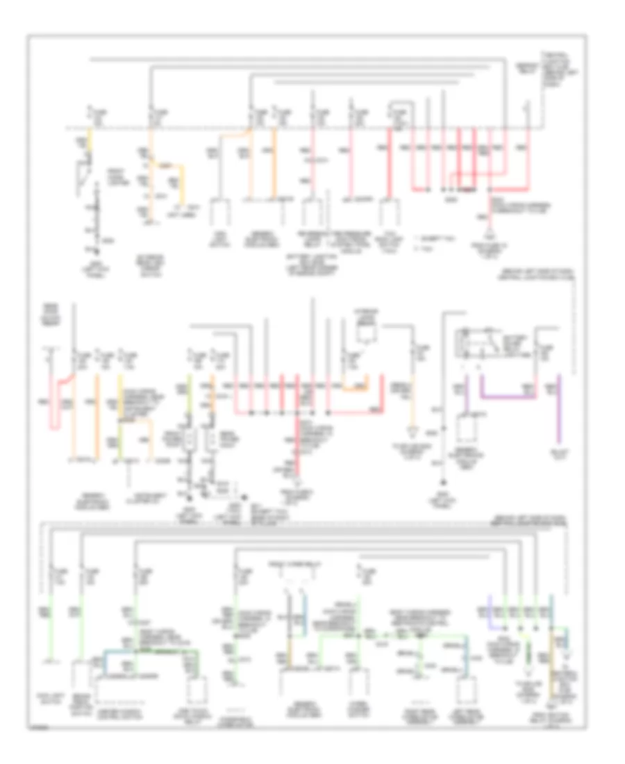
Power Distribution Wiring Diagram (2 of 3) for Ford Transit Connect XLT Premium 2013
 https://portal-diagnostov.com/license.html
Automotive Electricians Portal FZCO
Automotive Electricians Portal FZCO
https://portal-diagnostov.com/license.html
https://portal-diagnostov.com/license.html
Automotive Electricians Portal FZCO
Automotive Electricians Portal FZCOList of elements for Power Distribution Wiring Diagram (2 of 3) for Ford Transit Connect XLT Premium 2013:
- (behind left side of dash) central junction box (cjb)
- (body wiring harness, near breakout to c219) s308
- (body wiring harness, near breakout to restraints control module) s305
- (main wiring harness, near breakout to instrument cluster) s235
- (main wiring harness, near breakout to microphone) s231
- (not used)
- 1 of 3)
- Battery junction box (bjb) (left rear corner of engine compt)
- Battery saver relay (upfitter)
- Brake pedal position switch
- C201a
- C201b
- C201c
- C201d
- C201e
- C213
- C219
- C220b
- C237
- C2409a
- C3293a
- C3293b
- C423
- C438
- C510
- C610
- Central
- Cluster (ic)
- Defrost relay
- Except taxi
- Exterior rear view mirror switch
- From fuse 19 (diagram 1 of 3)
- From fuse 9 (diagram
- From ignition relay (diagram 1 of 3)
- Front cigar lighter
- Front power point
- Front wiper relay
- Fuse (taxi) 15a
- Fuse 10a
- Fuse 15a
- Fuse 20a
- Fuse 25a
- Fuse 5a
- Fuse 7.5a
- G200 (left kick panel)
- G200 (taxi) (left kick panel)
- G411 (except taxi) (base of right "d" pillar)
- Generic electronic module (gem)
- Generic electronics module (gem)
- Instrument
- Interior lamps relay
- Junction box (cjb) (behind left side of dash)
- Left rear wiper motor assembly
- Main light switch
- Master window control switch
- Nca
- One touch down window relay
- Rear door unlock relay
- Rear power point
- Red
- Reversing lamps relay
- Right rear wiper motor assembly
- S206
- S228
- S242 (main wiring harness, in breakout to cjb)
- S243 (main wiring harness, in breakout to cjb)
- S273 (main wiring harness, in breakout red
- S315
- Taxi
- Taxi roof lamp switch (taxi)
- Tire pressure monitoring system (tpms) module
- To centeral junction box (cjb) (diagram 1 of 3)
- To cjb) c213
- To splice s202 (diagram 3 of 3)
- To splice s205 (diagram 1 of 3)
- Windshield wiper motor
- Wiper/ washer switch
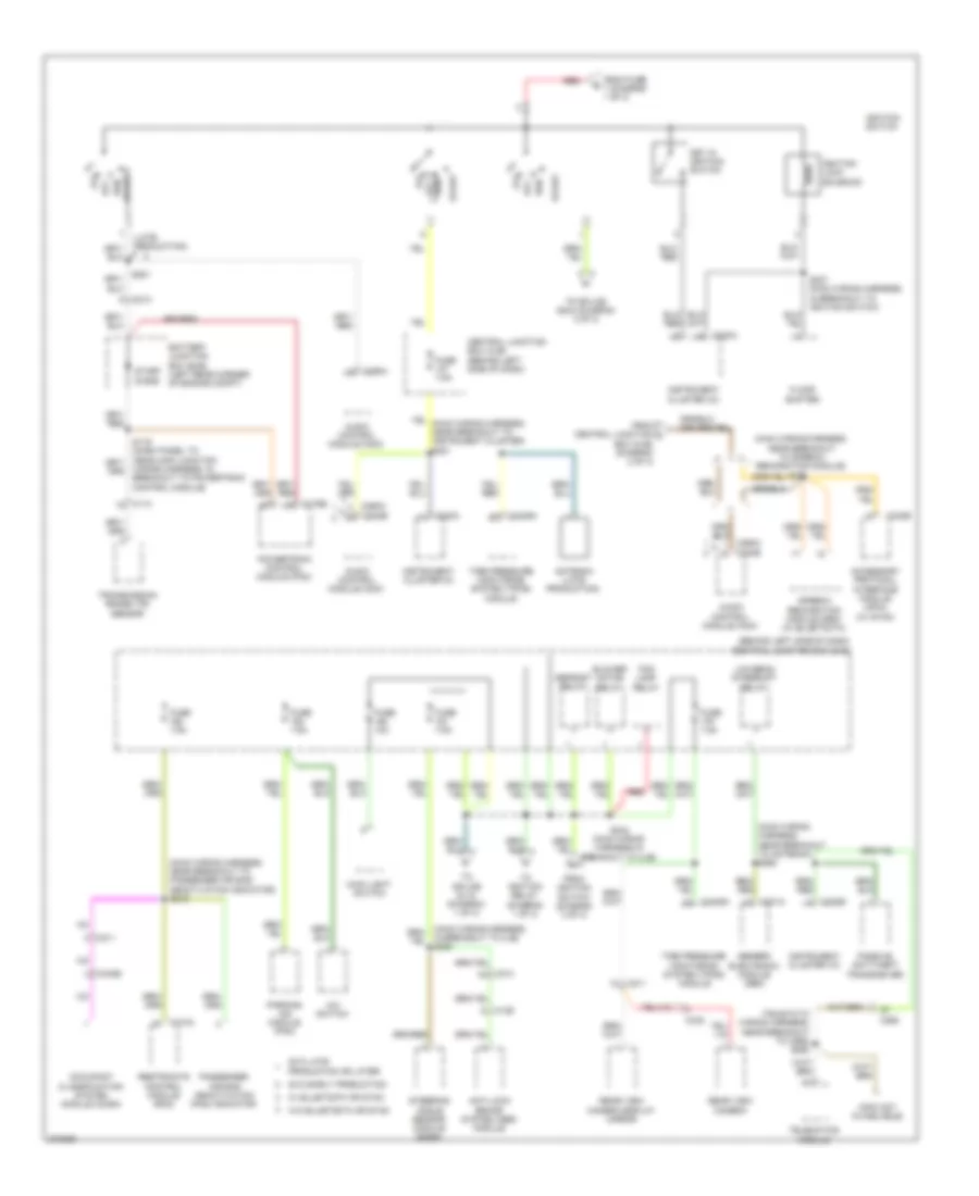
Power Distribution Wiring Diagram (3 of 3) for Ford Transit Connect XLT Premium 2013
 https://portal-diagnostov.com/license.html
Automotive Electricians Portal FZCO
Automotive Electricians Portal FZCO
https://portal-diagnostov.com/license.html
https://portal-diagnostov.com/license.html
Automotive Electricians Portal FZCO
Automotive Electricians Portal FZCOList of elements for Power Distribution Wiring Diagram (3 of 3) for Ford Transit Connect XLT Premium 2013:
- (behind left side of dash) central junction box (cjb)
- (info not avaiblable)
- (late production)
- (main wiring harness, near breakout to antenna) s260
- (main wiring harness, near breakout to passenger air bag deactivation indicator) s219
- (main wiring harness, near breakout to speech recognition module)
- (tbj2010-tc wiring harness, near breakout to c268) s250
- 2012 early production
- 2012 late
- A/c switch
- Acc
- Accessory protocol interface module (apim) (w/ sync)
- Antenna (late production)
- Anti-lock brake system (abs) module
- Audio control module (acm)
- Battery junction box (bjb) (left rear corner of engine compt)
- Blower motor relay
- Box (cjb) (diagram 2 of 3)
- C110
- C126
- C175b
- C201a
- C211
- C213
- C220a
- C220b
- C2409a
- C240b
- C268
- C290a
- C290a c240b
- C310a
- C340b
- C438
- Central junction box (cjb) (behind left side of dash)
- Defrost relay
- Floor shifter
- Fog lamp relay
- From central junction l
- From fuse 7 (diagram 1 of 3)
- From ignition switch (diagram 3 of 3)
- Fuse 10a
- Fuse 7.5a
- Generic electronic module (gem)
- Ignition lock solenoid
- Ignition switch
- In breakout to cjb) s280
- Instrument cluster (ic)
- Key in ignition switch
- Low beam interrupt relay
- Main light switch
- Occupant classification system module (ocsm)
- Off
- Parking aid module (pam)
- Passenger air bag deactivation (pad) indicator
- Passive anti-theft transceiver
- Powertrain control module (pcm)
- Production or later
- Rear view camera
- Rear view camera display mirror
- Red
- Restraints control module (rcm)
- Run
- Run acc
- S202
- S237 (main wiring harness, in breakout to ignition switch)
- S244 (main wiring harness,in breakout to cjb)
- S281
- Start
- Start diode
- Steering angle sensor module (sasm)
- Telematics module
- Tire pressure monitoring system (tpms) module
- To ignition relay (diagram 1 of 3)
- To splice s118 (diagram 1 of 3)
- To splice s244 (diagram 3 of 3)
- Transmission range (tr) sensor
- Wiring harness, in breakout to powertrain control module)
POWER DOOR LOCKS
Power Door Locks Wiring Diagram for Ford Transit Connect XLT Premium 2013
 https://portal-diagnostov.com/license.html
Automotive Electricians Portal FZCO
Automotive Electricians Portal FZCO
https://portal-diagnostov.com/license.html
https://portal-diagnostov.com/license.html
Automotive Electricians Portal FZCO
Automotive Electricians Portal FZCOList of elements for Power Door Locks Wiring Diagram for Ford Transit Connect XLT Premium 2013:
- (body wiring harness, near breakout to c339)
- (body wiring harness, near breakout to restraints control module) s311
- (not used)
- (right kick panel)
- 10-aa36
- 29-aa17
- 31s-aa17
- 31s-aa63
- 31s-aa64
- 31s-gl16
- 31s-gl20
- 31s-gl9
- 32-aa27
- 32-aa59
- 32aa-59
- 33-aa59
- 4-ec14
- 5-ec14
- All lock
- C201a
- C201b
- C201c
- C201d
- C201e
- C211
- C219
- C237
- C241
- C421
- C510
- C610
- Central junction box (cjb) (behind left side of dash)
- Computer data lines system
- Door unlock
- Dr ajar
- Driver side door lock unit (driver's door)
- Early production
- Fuse 20a
- G200 (left kick panel)
- G300
- G300 (right kick panel)
- G301 (left kick panel)
- G410 (base of left "d" pillar)
- G411 (base of right "d" pillar)
- Generic electronic module (gem) (lower left side of dash)
- Hot at all times
- Left sliding door ajar switch (base of left "c" pillar)
- Left sliding door contact switch (base of left "b" pillar)
- Left sliding door lock actuator (lower rear of sliding door)
- Lf dr ajar
- Lock pos
- Lock sw
- Ms can (+)
- Ms can (-)
- Nca
- Not used
- Passenger side door lock unit (passenger's door)
- Rear door lock unit
- Rear door unlock relay
- Rear dr ajar
- Red
- Rf dr ajar
- Right sliding door ajar switch (base of right "c" pillar)
- Right sliding door contact switch (base of right "b" pillar)
- Right sliding door lock actuator (lower rear of sliding door)
- Rke antenna
- S228
- S300
- S301
- S303
- S307 (body wiring harness, near breakout to restraints control module)
- S309 (body wiring harness, near breakout to c219)
- S312
- S315
- S501
- S600
- Unlock cabin
- Unlock rear
- Unlock sw
- Vbatt lock
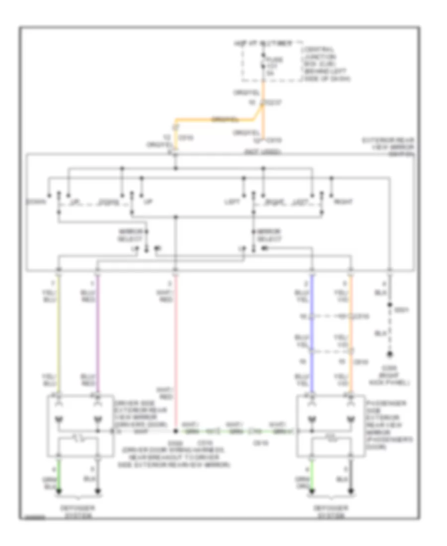
POWER MIRRORS
Power Mirrors Wiring Diagram for Ford Transit Connect XLT Premium 2013
 https://portal-diagnostov.com/license.html
Automotive Electricians Portal FZCO
Automotive Electricians Portal FZCO
https://portal-diagnostov.com/license.html
https://portal-diagnostov.com/license.html
Automotive Electricians Portal FZCO
Automotive Electricians Portal FZCOList of elements for Power Mirrors Wiring Diagram for Ford Transit Connect XLT Premium 2013:
- (not used)
- C237
- C510
- C610
- Central junction box (cjb) (behind left side of dash)
- Defogger system
- Down
- Driver side exterior rear view mirror (driver's door)
- Exterior rear view mirror switch
- Fuse 5a
- G300 (right kick panel)
- Hot at all times
- Left
- Mirror select
- Passenger side exterior rear view mirror (passenger's door)
- Right
- S500 (driver door wiring harness, near breakout to driver side exterior rearview mirror)
- S501
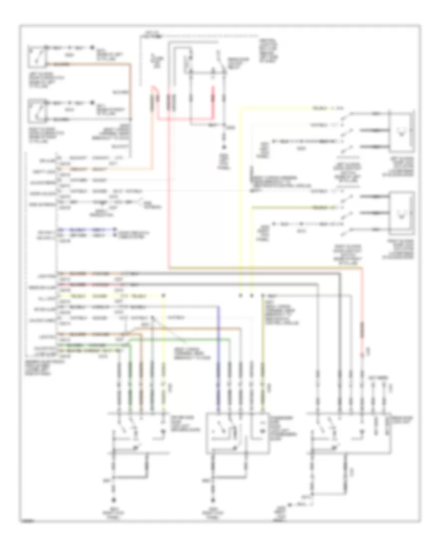
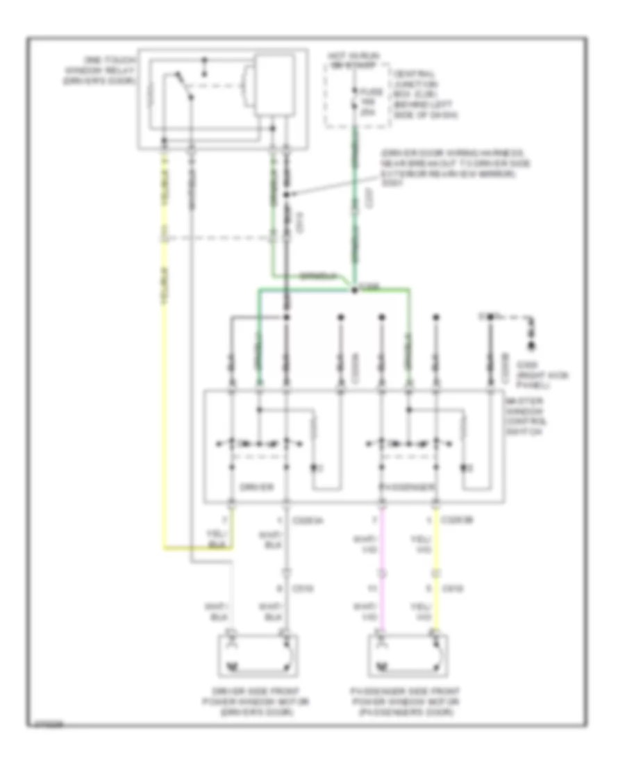
POWER WINDOWS
Power Windows Wiring Diagram for Ford Transit Connect XLT Premium 2013
 https://portal-diagnostov.com/license.html
Automotive Electricians Portal FZCO
Automotive Electricians Portal FZCO
https://portal-diagnostov.com/license.html
https://portal-diagnostov.com/license.html
Automotive Electricians Portal FZCO
Automotive Electricians Portal FZCOList of elements for Power Windows Wiring Diagram for Ford Transit Connect XLT Premium 2013:
- (driver door wiring harness, near breakout to driver side exterior rearview mirror) s501
- C237
- C3293a
- C3293b
- C510
- C610
- Central junction box (cjb) (behind left side of dash)
- Driver
- Driver side front power window motor (driver's door)
- Fuse 25a
- G300 (right kick panel)
- Hot in run or start
- Master window control switch
- One-touch window relay (driver's door)
- Passenger
- Passenger side front power window motor (passenger's door)
- S308
- S317
RADIO
Radio Wiring Diagram, Base for Ford Transit Connect XLT Premium 2013
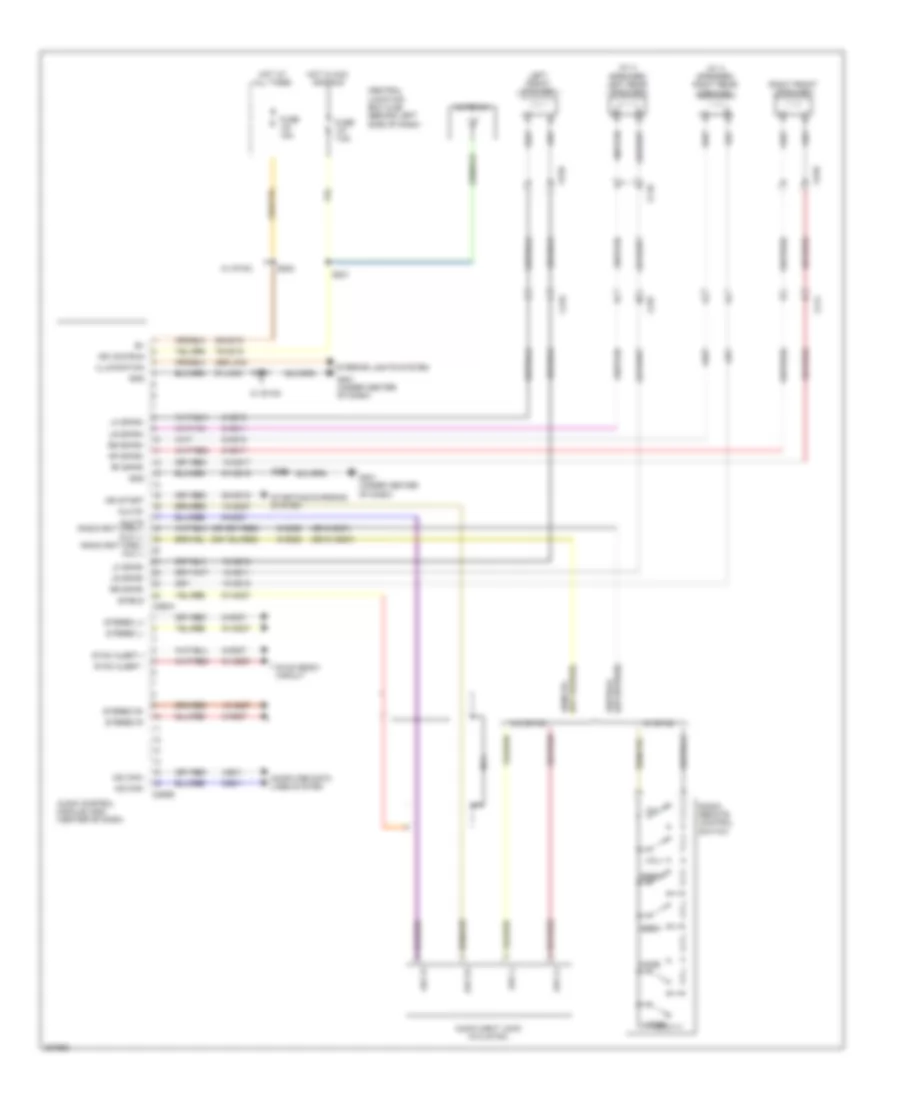 https://portal-diagnostov.com/license.html
Automotive Electricians Portal FZCO
Automotive Electricians Portal FZCO
https://portal-diagnostov.com/license.html
https://portal-diagnostov.com/license.html
Automotive Electricians Portal FZCO
Automotive Electricians Portal FZCOList of elements for Radio Wiring Diagram, Base for Ford Transit Connect XLT Premium 2013:
- (or 8-md27)
- (or 91-md27)
- (w/ 4 speaker) left rear speaker
- (w/ 4 speaker) right rear speaker
- 10-md10
- 10-md11
- 10-md17
- 10-md18
- 10-md27
- 29-md15
- 29s-lk34
- 4-ec1
- 5-ec1
- 50-md15
- 75-md15
- 8-md10
- 8-md11
- 8-md17
- 8-md18
- 8-md26
- 8-md27
- 9-md26
- 9-md27
- 91-lk34
- 91-md15
- 91-md27
- Antenna
- Audio control module (acm) (center of dash)
- Audio input jack (w/o sync)
- Aux l+
- Aux l-
- Aux r+
- Aux r-
- Aux r- radio rmt cnrl+/ aux l+
- C211
- C219
- C237
- C290a
- C290b
- C510
- C610
- C710
- Central junction box (cjb) (behind left side of dash)
- Computer data lines system
- Fuse 15a
- Fuse 7.5a
- G201 (under center of dash)
- Gnd
- Hot at all times
- Hot in acc and run
- Ign acc/run
- Ign start
- Illumination
- Interior lights system
- Left front speaker
- Lf spkr+
- Lf spkr-
- Lr spkr+
- Lr spkr-
- Mode
- Ms can+
- Ms can-
- Nca
- Radio remote control switch
- Radio rmt cnrl-/ aux l-
- Rf spkr+
- Rf spkr-
- Right front speaker
- Rr spkr+
- Rr spkr-
- S202
- S203
- S221
- Seek+
- Seek-
- Shield
- Starting/charging system
- Stereo l+
- Stereo l-
- Stereo r+
- Stereo r-
- Sync alert +
- Sync alert -
- Sync radio circuit
- Voice
- Vol+
- Vol-
- W/ sync
- W/o sync
Radio Wiring Diagram, Premium for Ford Transit Connect XLT Premium 2013
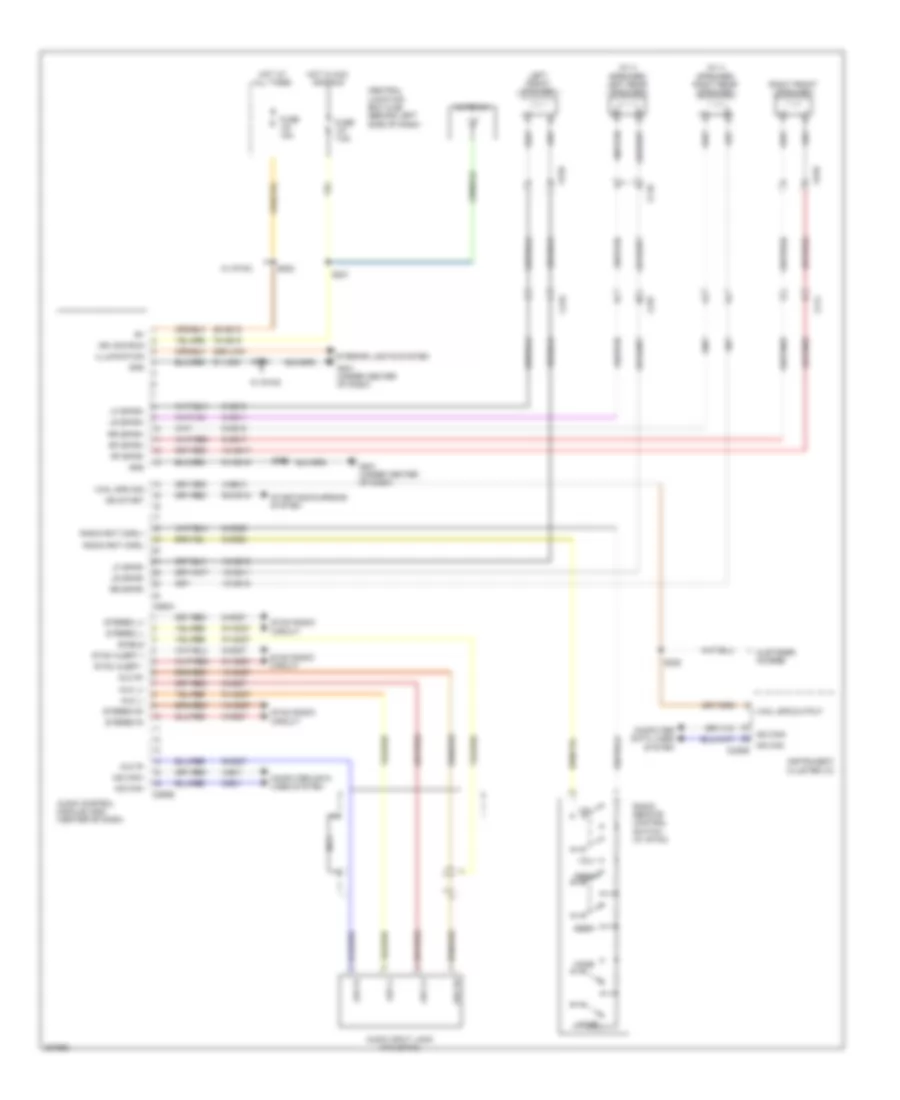 https://portal-diagnostov.com/license.html
Automotive Electricians Portal FZCO
Automotive Electricians Portal FZCO
https://portal-diagnostov.com/license.html
https://portal-diagnostov.com/license.html
Automotive Electricians Portal FZCO
Automotive Electricians Portal FZCOList of elements for Radio Wiring Diagram, Premium for Ford Transit Connect XLT Premium 2013:
- (w/ 4 speaker) left rear speaker
- (w/ 4 speaker) right rear speaker
- 10-md10
- 10-md11
- 10-md17
- 10-md18
- 10-md27
- 29-md15
- 29s-lk34
- 4-ec1
- 4-gb10
- 5-ec1
- 50-md15
- 75-md15
- 8-md10
- 8-md11
- 8-md17
- 8-md18
- 8-md26
- 8-md27
- 9-md26
- 9-md27
- 91-lk34
- 91-md15
- 91-md27
- Antenna
- Audio control module (acm) (center of dash)
- Audio input jack (w/o sync)
- Aux l+
- Aux l-
- Aux r+
- Aux r-
- C211
- C219
- C237
- C290a
- C290b
- C510
- C610
- C710
- Central junction box (cjb) (behind left side of dash)
- Computer data lines system
- Customer access
- Fuse 15a
- Fuse 7.5a
- G201 (under center of dash)
- Gnd
- Hot at all times
- Hot in acc and run
- Ign acc/run
- Ign start
- Illumination
- Instrument cluster (ic)
- Interior lights system
- Left front speaker
- Lf spkr+
- Lf spkr-
- Lr spkr+
- Lr spkr-
- Mode
- Ms can+
- Ms can-
- Ms can- c220b
- Nca
- Radio remote control switch (w/ sync)
- Radio rmt cnrl+
- Radio rmt cnrl-
- Rf spkr+
- Rf spkr-
- Right front speaker
- Rr spkr+
- Rr spkr-
- S202
- S203
- S221
- S222
- Seek+
- Seek-
- Shield
- Starting/charging system
- Stereo l+
- Stereo l-
- Stereo r+
- Stereo r-
- Sync alert +
- Sync alert -
- Sync radio circuit
- Vhcl spd output
- Vhcl spd sig
- Voice
- Vol+
- Vol-
- W/ sync
SYNC Radio Wiring Diagram for Ford Transit Connect XLT Premium 2013
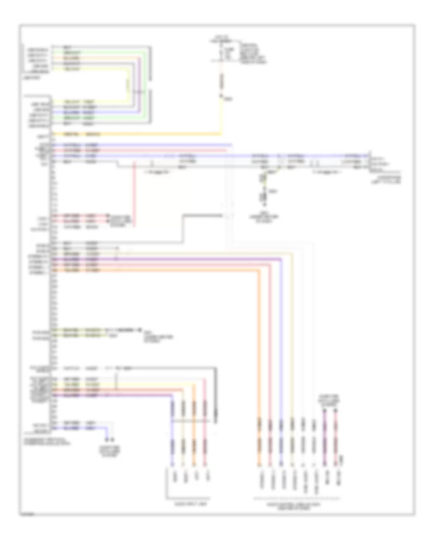 https://portal-diagnostov.com/license.html
Automotive Electricians Portal FZCO
Automotive Electricians Portal FZCO
https://portal-diagnostov.com/license.html
https://portal-diagnostov.com/license.html
Automotive Electricians Portal FZCO
Automotive Electricians Portal FZCOList of elements for SYNC Radio Wiring Diagram for Ford Transit Connect XLT Premium 2013:
- 10-md27
- 29-mc12
- 3-mc8
- 3-md27
- 4-ec1
- 4-mc27
- 5-ec1
- 5-mc27
- 6-md27
- 7-md27
- 8-mc8
- 8-md27
- 89-mc8
- 9-md27
- 91-mc12
- 91-md27
- Accessory protocol interface module (apim)
- Alert + sync alert -
- Audio control module (acm) (center of dash)
- Audio input jack
- Aux audio
- Aux audio in right -
- C211
- C290b
- Central junction box (cjb) (behind left side of dash)
- Computer data lines system
- Fuse 15a
- G201 (under center of dash)
- Hot at all times
- Hs can +
- Hs can -
- I can +
- I can -
- In left + aux audio in left - aux audio in right +
- Left +
- Left -
- Mic +
- Mic -
- Mic in +
- Mic in -
- Mic pwr +
- Microphone (left "a" pillar)
- Ms can +
- Ms can -
- Nca
- Pwr gnd
- Right +
- Right -
- S202
- S203
- Shield
- Stereo l +
- Stereo l -
- Stereo r +
- Stereo r -
- Sync
- Sync alert +
- Sync alert -
- Usb data +
- Usb data -
- Usb gnd
- Usb port
- Usb shield
- Usb vbus
- Vbatt
SHIFT INTERLOCK
Shift Interlock Wiring Diagram for Ford Transit Connect XLT Premium 2013
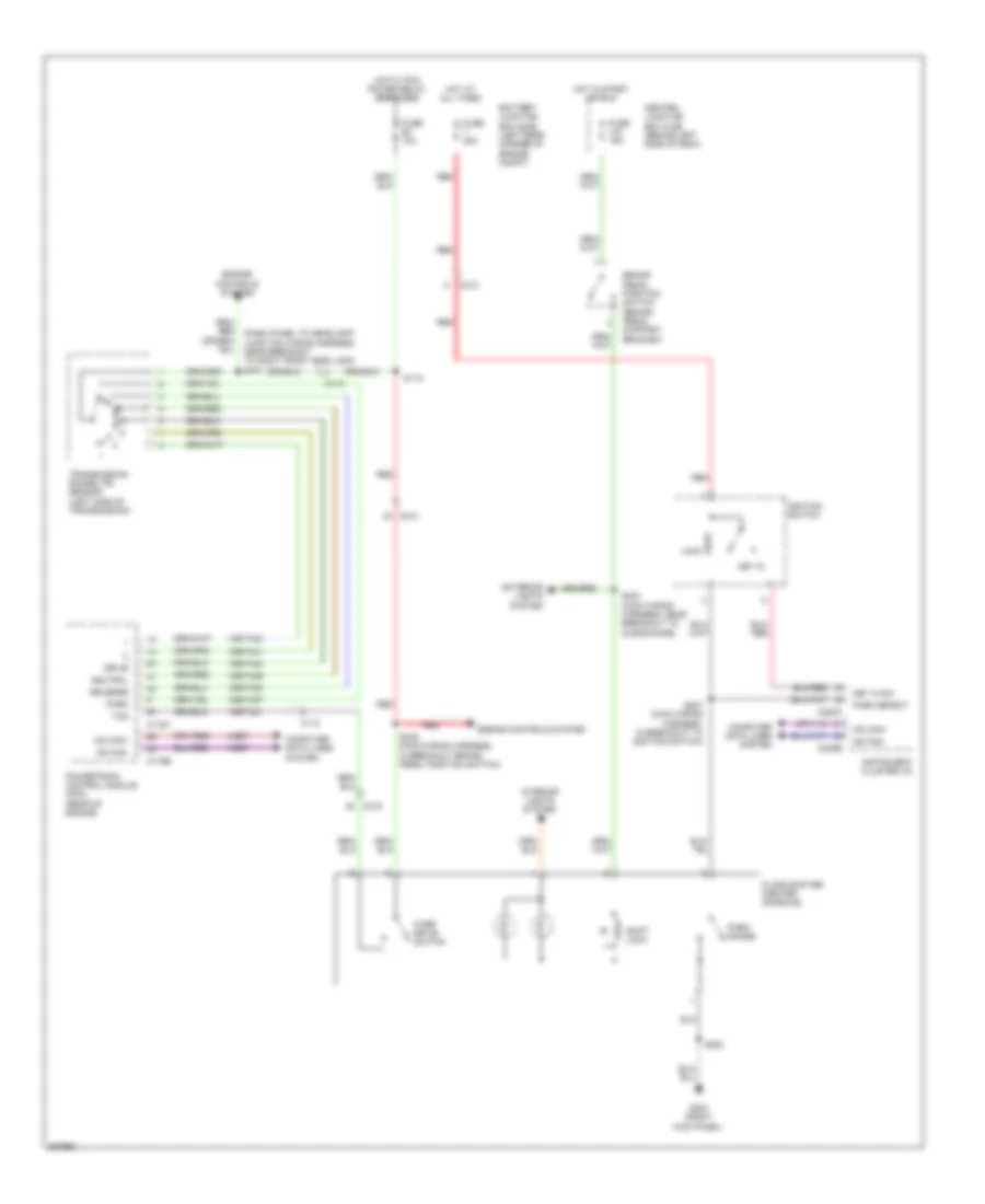 https://portal-diagnostov.com/license.html
Automotive Electricians Portal FZCO
Automotive Electricians Portal FZCO
https://portal-diagnostov.com/license.html
https://portal-diagnostov.com/license.html
Automotive Electricians Portal FZCO
Automotive Electricians Portal FZCOList of elements for Shift Interlock Wiring Diagram for Ford Transit Connect XLT Premium 2013:
- 15s-ta21
- 15s-ta37
- 15s-ta38
- 15s-ta39
- 15s-ta40
- 15s-ta41
- 15s-ta42
- 4-ec7
- 5-ec7
- Battery junction box (bjb) (left rear corner of engine compt)
- Brake pedal position switch (brake pedal support bracket)
- C110
- C175b
- C175t
- C213
- C215
- C220a
- C220b
- Central junction box (cjb) (behind left side of dash)
- Computer data lines system
- Drive
- Engine controls system
- Exterior lights system
- Floor shifter (center console)
- Fuse 10a
- Fuse 15a
- Fuse 20a
- G203 (right kick panel)
- Hot at all times
- Hot in start or run
- Hot w/ pcm power relay energized
- Hs can+
- Hs can-
- Ignition switch
- Instrument cluster (ic)
- Interior lights system
- Key in
- Key in sw
- Lock
- Ms can+
- Ms can-
- Neutral
- Over drive switch
- Park
- Park detect
- Park range
- Powertrain control module (pcm) (rear of engine)
- Red
- Reverse
- S112
- S220
- S234 (main wiring harness, near breakout to microphone)
- S236 (main wiring harness, in breakout brake pedal position switch)
- S237 (main wiring harness, in breakout to ignition switch)
- Shift lock
- Tcs
- Transmission range (tr) sensor (left side of transmission)
STARTING/CHARGING
Charging Wiring Diagram for Ford Transit Connect XLT Premium 2013
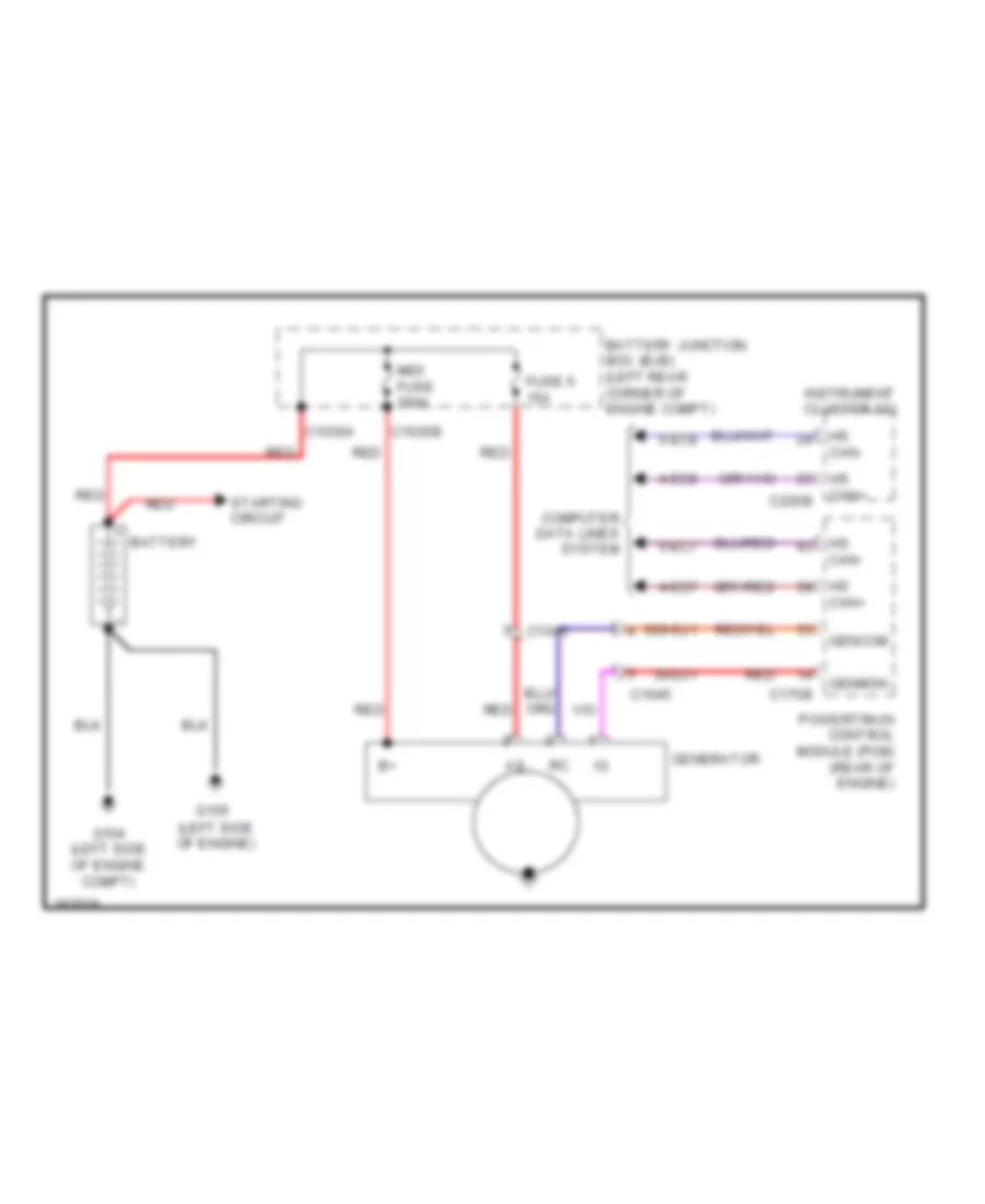 https://portal-diagnostov.com/license.html
Automotive Electricians Portal FZCO
Automotive Electricians Portal FZCO
https://portal-diagnostov.com/license.html
https://portal-diagnostov.com/license.html
Automotive Electricians Portal FZCO
Automotive Electricians Portal FZCOList of elements for Charging Wiring Diagram for Ford Transit Connect XLT Premium 2013:
- 30-dj1
- 30s-dj1
- 4-ec7
- 4-ec8
- 5-ec7
- 5-ec8
- Battery
- Battery junction box (bjb) (left rear corner of engine compt)
- C1035a
- C1035b
- C1045
- C175b
- C220b
- Can+
- Computer data lines system
- Fuse 6 15a
- G104 (left side of engine compt)
- G105 (left side of engine)
- Gencom
- Generator
- Genmon
- Hs can-
- Instrument cluster (ic)
- Midi fuse 200a
- Powertrain control module (pcm) (rear of engine)
- Red
- Starting circuit
Starting Wiring Diagram for Ford Transit Connect XLT Premium 2013
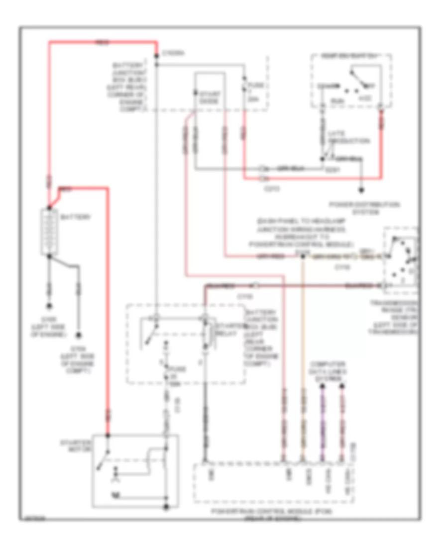 https://portal-diagnostov.com/license.html
Automotive Electricians Portal FZCO
Automotive Electricians Portal FZCO
https://portal-diagnostov.com/license.html
https://portal-diagnostov.com/license.html
Automotive Electricians Portal FZCO
Automotive Electricians Portal FZCOList of elements for Starting Wiring Diagram for Ford Transit Connect XLT Premium 2013:
- (dash panel to headlamp
- 31-bb16
- 4-ec7
- 5-ec7
- 50-bb14
- 50-bb15
- Acc
- Battery
- Battery junction box (bjb) (left rear corner of engine compt)
- C1035a
- C110
- C139
- C175b
- C213
- Computer data lines system
- Fuse 20a
- Fuse 30a
- G104 (left side of engine compt)
- G105 (left side of engine)
- Hs can+
- Hs can-
- Ignition switch
- Junction wiring harness, in breakout to powertrain control module)
- Late production
- Off
- Power distribution system
- Powertrain control module (pcm) (rear of engine)
- Red
- Run
- S116
- S281
- Smc
- Smcs
- Smr
- Start
- Start diode
- Starter motor
- Starter relay
- Transmission range (tr) sensor (left side of transmission)
SUPPLEMENTAL RESTRAINTS
Supplemental Restraints Wiring Diagram (1 of 2) for Ford Transit Connect XLT Premium 2013
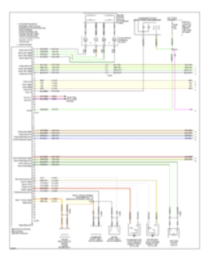 https://portal-diagnostov.com/license.html
Automotive Electricians Portal FZCO
Automotive Electricians Portal FZCO
https://portal-diagnostov.com/license.html
https://portal-diagnostov.com/license.html
Automotive Electricians Portal FZCO
Automotive Electricians Portal FZCOList of elements for Supplemental Restraints Wiring Diagram (1 of 2) for Ford Transit Connect XLT Premium 2013:
- (body wiring harness, near breakout to restraints control module) s310
- 15-ja10
- 15-ja39
- 15-ja40
- 15s-ja15
- 15s-ja31
- 15s-ja32
- 15s-ja33
- 15s-ja34
- 15s-ja37
- 15s-ja48
- 15s-ja8
- 4-ec5
- 5-ec5
- 7-ja49
- 7-ja53
- 8-ja54
- 8-ja55
- 9-ja10
- 9-ja49
- 90s-ja34
- 91-ja39
- 91-ja40
- 91s-ja15
- 91s-ja31
- 91s-ja32
- 91s-ja33
- 91s-ja37
- 91s-ja48
- 91s-ja56
- 91s-ja8
- C310a
- C310b
- C3249
- C339a
- C339b
- C339c
- C340d
- Case ground
- Central junction box (cjb) (behind left side of dash)
- Clock spring (steering column)
- Computer data lines system
- Driver air bag module (in steering wheel)
- Driver safety belt buckle sensor
- Driver seat position sensor (under driver seat)
- Driver side impact sensor (base of left "b" pillar)
- Drv buckle sw-in
- Drvr ab1 feed
- Drvr ab1 rtn
- Drvr ab2 feed
- Drvr ab2 rtn
- Drvr pretens feed
- Drvr pretens rtn
- Drvr sab feed
- Drvr sab rtn
- Drvr1 feed
- Drvr1 rtn
- Fcs1 feed
- Fcs1 rtn
- Fcs2 feed
- Fcs2 rtn
- Fuse 7.5a
- Hot in run or start
- Left side air bag module
- Ms can +
- Ms can -
- Nca
- Pad lp
- Pass ab1 feed
- Pass ab1 rtn
- Pass ab2 feed
- Pass ab2 rtn
- Pass buckle sw-in
- Pass pretens feed
- Pass pretens rtn
- Pass sab feed
- Pass sab rtn
- Pass1 feed
- Pass1 rtn
- Passenger air bag deactivation (pad) indicator
- Passenger safety belt buckle sensor
- Passenger side impact sensor (base of right "b" pillar)
- Pin shorting bar is engaged when module connector is disconnected from harness. (shorting bars are connected between the following pins: 1-2, 3-4, 7-8, & 9-10 c310a 7-8, 9-10, 17-18 & 19-20 c310b
- Restraints control module (rcm) (center console)
- S219
- Seat track feed
- Sens gnd
- Shorting bar
- Vpwr
Supplemental Restraints Wiring Diagram (2 of 2) for Ford Transit Connect XLT Premium 2013
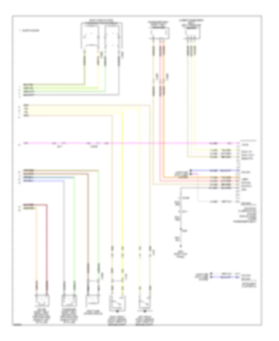 https://portal-diagnostov.com/license.html
Automotive Electricians Portal FZCO
Automotive Electricians Portal FZCO
https://portal-diagnostov.com/license.html
https://portal-diagnostov.com/license.html
Automotive Electricians Portal FZCO
Automotive Electricians Portal FZCOList of elements for Supplemental Restraints Wiring Diagram (2 of 2) for Ford Transit Connect XLT Premium 2013:
- (right side of dash) passenger air bag module
- (under passenger's seat) seat pressure sensor
- 14-ja60
- 4-ja60
- 5-ja60
- 7-ja52
- 7-ja59
- 8-ja52
- 8-ja59
- 9-ja52
- 9-ja59
- 91-ja60
- Bts rtn
- Bts sig
- C110
- C211
- C215
- C256a
- C256b
- C340a
- C340b
- C340e
- C340f
- Computer data lines system
- Driver safety belt retractor pretensioner (base of left "b" pillar)
- G203 (right kick panel)
- Gnd
- Instrument cluster (ic)
- Left front impact sensor (left front of engine compt)
- Ms can+
- Ms can-
- Nca
- Occupant classification system module (ocsm) (under passenger's seat)
- Passenger safety belt retractor pretensioner (base of right "b" pillar)
- Passenger seat safety belt tensioner
- Right front impact sensor (right front of engine compt)
- Right side air bag module
- S220
- Sens rtn
- Shorting bar
- Sws v-in
- Sws v-out
- Vpwr
- Vref1
TRANSMISSION
Transmission Wiring Diagram for Ford Transit Connect XLT Premium 2013
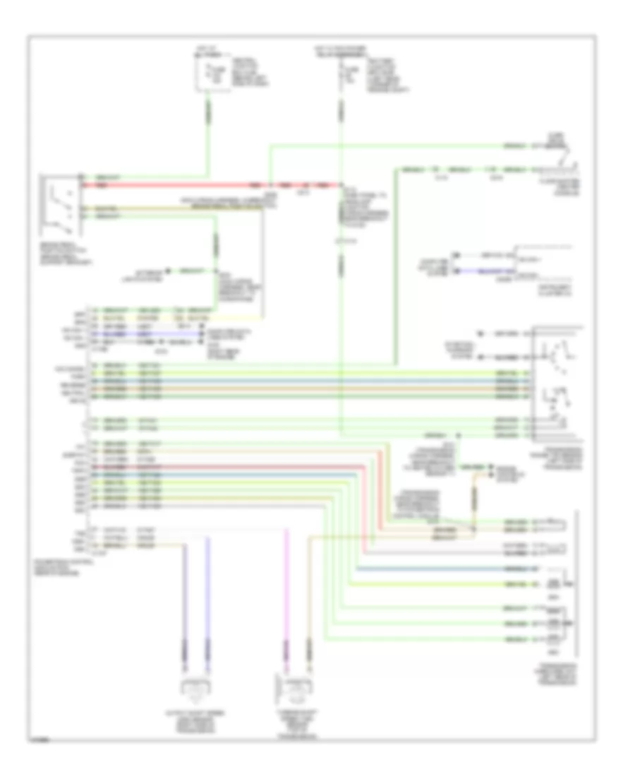 https://portal-diagnostov.com/license.html
Automotive Electricians Portal FZCO
Automotive Electricians Portal FZCO
https://portal-diagnostov.com/license.html
https://portal-diagnostov.com/license.html
Automotive Electricians Portal FZCO
Automotive Electricians Portal FZCOList of elements for Transmission Wiring Diagram for Ford Transit Connect XLT Premium 2013:
- (transmission wiring harness, near breakout to powertrain control module) s131
- 0ss-
- 15-ta41
- 15-ta42
- 15s-lg23
- 15s-ta17
- 15s-ta21
- 15s-ta23
- 15s-ta24
- 15s-ta37
- 15s-ta38
- 15s-ta39
- 15s-ta40
- 15s-ta63
- 15s-ta64
- 15s-ta65
- 31-re8
- 4-ec7
- 5-ec7
- 8-rj29
- 8-ta27
- 8-ta36
- 9-pa1
- 9-rj29
- 91s-pg6
- 91s-ta17
- Battery junction box (bjb) (left rear corner of engine compt)
- Bpp
- Bps
- Brake pedal position switch (brake pedal support bracket)
- C110
- C175b
- C175t
- C213
- C215
- C220b
- Central junction box (cjb) (behind left side of dash)
- Computer data lines system
- Drive
- Engine controls system
- Exterior lights system
- Floor shifter (center console)
- Fuse 10a
- Fuse 15a
- G100 (right rear of engine)
- Gnd
- Hot at all times
- Hot w/ pcm power relay energized
- Hs can +
- Hs can -
- Instrument cluster (ic)
- Neutral
- O/d cancel
- Oss+
- Output shaft speed (oss) sensor (right side of transmission)
- Over/ drive switch
- Park
- Pca
- Powertrain control module (pcm) (rear of engine)
- Red
- Reverse
- S101 (transmission wiring harness, near breakout to heated oxygen sensor 11)
- S103
- S234 (main wiring harness, near breakout to microphone)
- S236 (main wiring harness, in breakout brake pedal position switch)
- Sigrtnt
- Ssa
- Ssb
- Ssc
- Ssd
- Sse
- Starting/ charging system
- Tft
- Transmission hardware unit (left rear of transmission)
- Transmission range (tr) sensor (left side of transmission)
- Tspc
- Tss
- Turbine shaft speed (tss) sensor (top of transmission)
WARNING SYSTEMS
Chime Wiring Diagram for Ford Transit Connect XLT Premium 2013
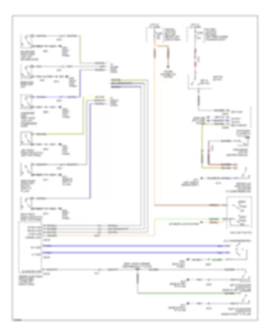 https://portal-diagnostov.com/license.html
Automotive Electricians Portal FZCO
Automotive Electricians Portal FZCO
https://portal-diagnostov.com/license.html
https://portal-diagnostov.com/license.html
Automotive Electricians Portal FZCO
Automotive Electricians Portal FZCOList of elements for Chime Wiring Diagram for Ford Transit Connect XLT Premium 2013:
- (base of right "d" pillar)
- (body wiring harness, near breakout to c219) s309
- (passenger's door)
- Battery junction box (bjb) (left rear corner of engine compt)
- Brake fluid level switch (on master cylinder reservoir)
- Brk warning
- C201b
- C201e
- C211
- C213
- C219
- C220a
- C220b
- C421
- C423
- C510
- C610
- Central junction box (cjb) (behind left side of dash)
- Computer data lines system
- Driver side front door lock unit (driver's door)
- Exterior lights system
- Fuse 10a
- Fuse 20a
- G101 (left side of engine compt)
- G203 (right kick panel)
- G300 (right kick panel)
- G301 (left kick panel)
- G410 (base of left "d" pillar)
- G411
- G411 (base of right "d" pillar)
- Generic electronic module (gem) (lower left side of dash)
- Head
- Hot at all times
- Hs can +
- Hs can -
- Ignition
- Ignition switch
- Instrument cluster (ic)
- Key in
- Key-in sw
- Left front door ajar switch (left kick panel)
- Left sliding door ajar switch (base of left "c" pillar)
- Lf dr ajar
- Lf turn
- License lamp
- Main light switch
- Multi-function switch
- Off
- Park
- Park brake switch (center console)
- Passenger side front door lock unit
- Power distribution system
- Rear door door lock unit
- Rear doors door ajar switch (right "d" pillar)
- Red
- Rf dr ajar
- Rh turn
- Right front door ajar switch (right kick panel)
- Right sliding door ajar switch (base of right "c" pillar)
- Rr dr ajar
- S115
- S220
- S300
- S303
- S312
- S315
- S417
- S501
- S600
- Sliding dr ajar
- W/ manual door locks
- W/ power door locks
Tire Pressure Monitoring Wiring Diagram for Ford Transit Connect XLT Premium 2013
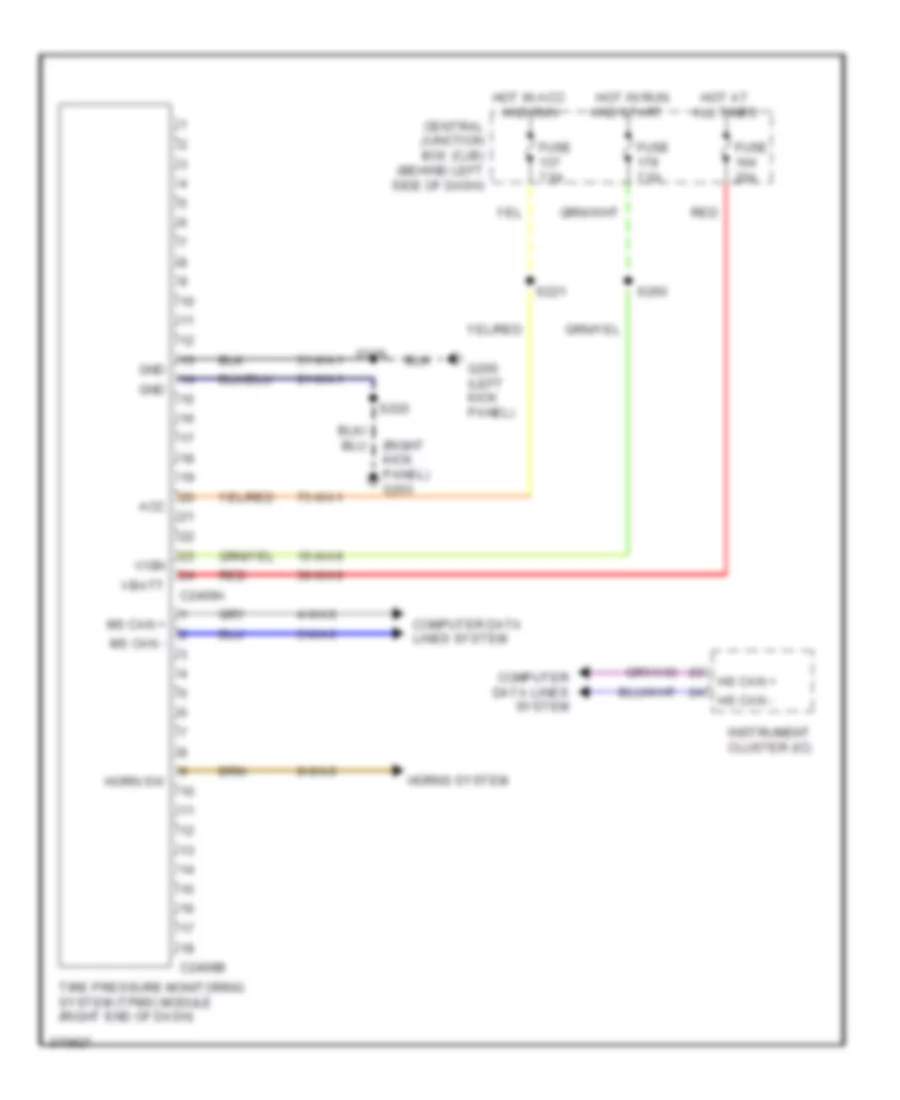 https://portal-diagnostov.com/license.html
Automotive Electricians Portal FZCO
Automotive Electricians Portal FZCO
https://portal-diagnostov.com/license.html
https://portal-diagnostov.com/license.html
Automotive Electricians Portal FZCO
Automotive Electricians Portal FZCOList of elements for Tire Pressure Monitoring Wiring Diagram for Ford Transit Connect XLT Premium 2013:
- (right kick panel) g203
- 15-wa6
- 30-wa6
- 31-wa1
- 4-wa6
- 5-wa6
- 75-wa1
- 9-wa6
- 91-wa1
- Acc
- C2409a
- C2409b
- Central junction box (cjb) (behind left side of dash)
- Computer data lines system
- Fuse 20a
- Fuse 7.5a
- G200 (left kick panel)
- Gnd
- Horn sw
- Horns system
- Hot at all times
- Hot in acc and run
- Hot in run and start
- Hs can +
- Hs can -
- Instrument cluster (ic)
- Ms can +
- Ms can -
- Red
- S220
- S221
- S228
- S260
- Tire pressure monitoring system (tpms) module (right end of dash)
- Vbatt
- Vign
WIPER/WASHER
Wiper/Washer Wiring Diagram for Ford Transit Connect XLT Premium 2013
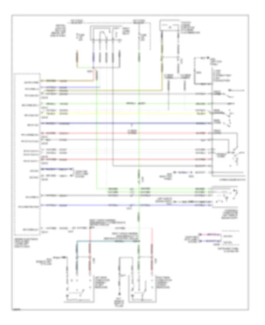 https://portal-diagnostov.com/license.html
Automotive Electricians Portal FZCO
Automotive Electricians Portal FZCO
https://portal-diagnostov.com/license.html
https://portal-diagnostov.com/license.html
Automotive Electricians Portal FZCO
Automotive Electricians Portal FZCOList of elements for Wiper/Washer Wiring Diagram for Ford Transit Connect XLT Premium 2013:
- (base of right "d" pillar)
- (body wiring harness, near breakout to restraints control module)
- (body wiring harness, near breakout to restraints control module) s305
- (left side of engine compt) g101
- 1) high 2) low 3) intermittent 4) off 5) single pass
- 15-ka28
- 15-ka9
- 31-ka8
- 32-ka11
- 32-ka28
- 32-ka34
- 32-ka9
- 33-ka34
- 4-ec14
- 5-ec14
- 8-ka45
- 8-ka46
- 8-ka47
- 91s-ka11
- 91s-ka35
- C201a
- C201b
- C201c
- C201e
- C213
- C219
- C220b
- C423
- C438
- Central junction box (cjb) (behind left side of dash)
- Computer data lines system
- Fr hi speed sw
- Fr int data 1
- Fr int data 2
- Fr int data 3
- Fr int/auto sw
- Fr wash sw
- Fr wiper hi
- Fr wiper lo
- Fr wiper prk pos
- Front wiper
- Front wiper relay
- Fuse 20a
- G200 (left kick panel)
- G203 (right kick panel)
- G410 (base of left "d" pillar)
- G411
- Generic electronic module (gem) (lower left side of dash)
- Hot in run or start
- Ign fr wiper
- Instrument panel cluster (ipc)
- Left rear wiper motor assembly (in left rear door)
- Ms can+
- Ms can-
- Nca
- Off
- Rear washer
- Rear wiper
- Right rear wiper motor assembly (in right rear door)
- Rr int sw
- Rr wash sw
- Rr wiper out
- Rr wiper sply
- S109
- S220
- S228
- S231
- S239
- S304
- S417
- Two-way washer pump motor (in washer fluid reservoir)
- Variable interm
- W/ rear wipers
- W/o rear wipers
- Windshield wiper motor (left rear of engine compt)
- Wiper/washer switch

 Čeština
 Dansk
Dansk Deutsch
 Ελληνικά
 English
 English
 Español
 Suomi
Suomi Français
 Français
 עברית
עברית Hrvatski
 Magyar
 Italiano
 한국어
한국어 Nederlands
 Polski
 Português
 Português
 Română
 Русский
 Slovenčina
 Slovenščina
 Svenska
 Türkçe
 中文 (中国)
