ANTI-LOCK BRAKES
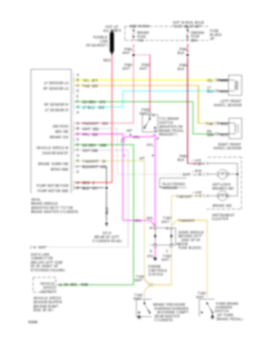
All-Wheel ABS Wiring Diagram, with DRL for GMC Jimmy 1994
 https://portal-diagnostov.com/license.html
Automotive Electricians Portal FZCO
Automotive Electricians Portal FZCO
https://portal-diagnostov.com/license.html
https://portal-diagnostov.com/license.html
Automotive Electricians Portal FZCO
Automotive Electricians Portal FZCO
List of elements for All-Wheel ABS Wiring Diagram, with DRL for GMC Jimmy 1994:
- (at park
- (behind left side of i/p, above fuse
- * **
- **analog
- *electronic
- 4wal brake module (mounted next to the brake master cylinder)
- A/t
- A15
- A16
- Abs ind
- Anti-lock brakes ind.
- B16
- Block)
- Bpmv gnd
- Brake fuse 15a
- Brake ind.
- Brake pedal)
- Brake pressure
- Brake sw
- Brake warn ind
- Cluster
- Cylinder)
- Data link connector (below left side of i/p, right of steering column)
- Diag request
- Diode
- Drl module
- Engine controls system
- Fuse block: i/p
- Fusible link (16 ga-rust)
- G114 (rear of left cylinder head)
- Hot at all times
- Hot in run
- Hot in run, bulb test or start
- Ign feed
- Ign/gau fuse 20a
- Ignition switch
- Instrument
- Left front wheel sensor
- Lf sensor hi
- Lf sensor lo
- M/t
- Module
- Nca
- Near master
- Output
- Park brake
- Pnk/
- Pump motor gnd
- Pump motor pwr
- Red
- Rf sensor hi
- Rf sensor lo
- Right front wheel sensor
- Speed
- Switch
- Tan
- Tan/ a
- Tcc brake switch (mounted on brake pedal bracket)
- Vehicle
- Vehicle speed in
- Vehicle speed sensor buffer (behind right side of i/p)
- Warning
- Warning warning (in engine compt,
All-Wheel ABS Wiring Diagram, without DRL for GMC Jimmy 1994
 https://portal-diagnostov.com/license.html
Automotive Electricians Portal FZCO
Automotive Electricians Portal FZCO
https://portal-diagnostov.com/license.html
https://portal-diagnostov.com/license.html
Automotive Electricians Portal FZCO
Automotive Electricians Portal FZCOList of elements for All-Wheel ABS Wiring Diagram, without DRL for GMC Jimmy 1994:
- (at park
- (behind left side of i/p,
- * **
- **analog
- *electronic
- 4wal brake module (mounted next to the brake master cylinder)
- A/t
- A15
- A16
- Above
- Abs ind
- Anti-lock brakes ind.
- B16
- Bpmv gnd
- Brake fuse 15a
- Brake ind.
- Brake pedal)
- Brake pressure
- Brake sw
- Brake warn ind
- Cluster
- Cylinder)
- Data link connector (below left side of i/p, right of steering column)
- Diag request
- Diode module
- Engine controls system
- Fuse block)
- Fuse block: i/p
- Fusible link (16 ga-rust)
- G114 (rear of left cylinder head)
- Hot at all times
- Hot in run
- Hot in run, bulb test or start
- Ign feed
- Ign/gau fuse 20a
- Instrument
- Left front wheel sensor
- Lf sensor hi
- Lf sensor lo
- M/t
- Nca
- Near master
- Output
- Park brake
- Pnk/
- Pump motor gnd
- Pump motor pwr
- Red
- Rf sensor hi
- Rf sensor lo
- Right front wheel sensor
- Speed
- Switch
- Tan
- Tcc brake switch (mounted on brake pedal bracket)
- Vehicle
- Vehicle speed in
- Vehicle speed sensor buffer (behind right side of i/p)
- Warning
- Warning warning (in engine compt,
COMPUTER DATA LINES
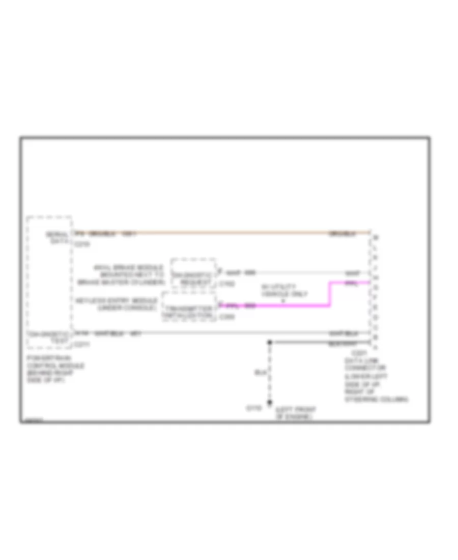
Data Link Connector Wiring Diagram for GMC Jimmy 1994
 https://portal-diagnostov.com/license.html
Automotive Electricians Portal FZCO
Automotive Electricians Portal FZCO
https://portal-diagnostov.com/license.html
https://portal-diagnostov.com/license.html
Automotive Electricians Portal FZCO
Automotive Electricians Portal FZCOList of elements for Data Link Connector Wiring Diagram for GMC Jimmy 1994:
- (left front of engine)
- (lower left side of i/p, right of steering column)
- (mounted next to
- (under console)
- 4wal brake module
- A14 diagnostic test c211
- Brake master cylinder)
- C221
- Data link connector
- Diagnostic request c152
- F9 serial data c210
- G110
- Keyless entry module
- Powertrain control module (behind right side of i/p)
- Transmitter initialization c350
- W/ utility vehicle only
CRUISE CONTROL
4.3L
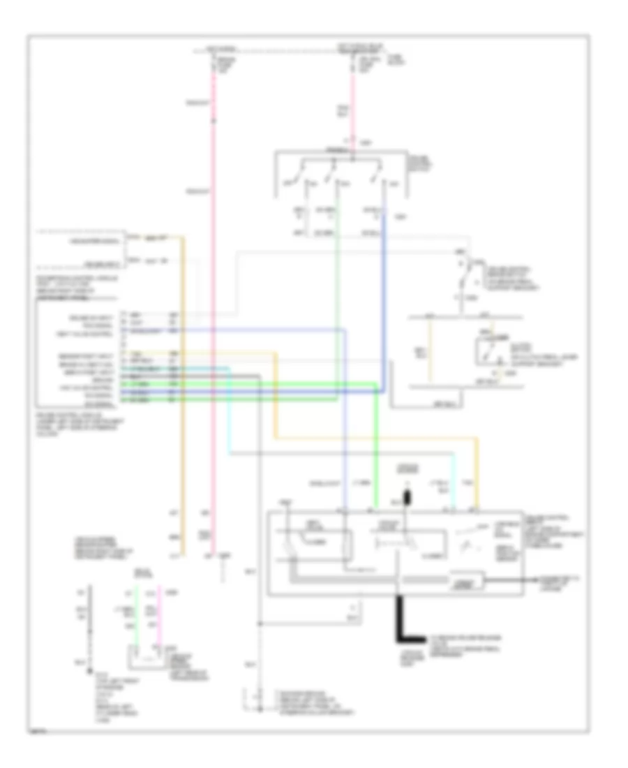
4.3L (VIN W), Cruise Control Wiring Diagram for GMC Jimmy 1994
 https://portal-diagnostov.com/license.html
Automotive Electricians Portal FZCO
Automotive Electricians Portal FZCO
https://portal-diagnostov.com/license.html
https://portal-diagnostov.com/license.html
Automotive Electricians Portal FZCO
Automotive Electricians Portal FZCOList of elements for 4.3L (VIN W), Cruise Control Wiring Diagram for GMC Jimmy 1994:
- (behind right side of instrument panel)
- (on brake pedal
- (on clutch pedal lever
- (vin w & vinz)
- (vin w)
- (vinz)
- A/t
- B10
- Brake fuse 15a
- Brake in (vent/vac)
- Bus bar ground (behind left side of
- C11
- C12
- C251
- C252
- C253
- C255
- C320
- Closed
- Clutch switch
- Connected to throttle linkage
- Cruise control brake switch
- Cruise control module (under left side of instrument
- Cruise control servo (left side of engine compartment, on inner wheelhouse)
- Cruise control switch
- Cruise input
- Cruise on input
- Cylinder head)
- F13
- Fuse block
- G110 (top left front
- G114 (rear of left
- Ground
- Hot in run
- Hot in run, bulb test or start
- Ign /gau fuse 20a
- Instrument panel)
- Instrument panel, on steering column bracket)
- M/t
- Of engine)
- Off
- Panel, left side of steering column)
- Pcm signal
- Pnk/
- Powertrain control module (pcm) (behind right side of
- R/a
- R/a signal
- S/c
- S/c signal
- Sensor posit input
- Servo posit input
- Servo position sensor
- Solid state
- Support bracket)
- Tan
- To brake cruise release valve (vents with brake pedal depressed)
- Vac valve control
- Vacuum motor
- Vacuum release port
- Vacuum source
- Vacuum valve
- Variable a/c signal
- Vehicle speed sensor (left rear of transmission)
- Vehicle speed sensor buffer
- Vent
- Vent valve
- Vent valve control
- Vss buffer signal
4.3L (VIN Z), Cruise Control Wiring Diagram for GMC Jimmy 1994
 https://portal-diagnostov.com/license.html
Automotive Electricians Portal FZCO
Automotive Electricians Portal FZCO
https://portal-diagnostov.com/license.html
https://portal-diagnostov.com/license.html
Automotive Electricians Portal FZCO
Automotive Electricians Portal FZCOList of elements for 4.3L (VIN Z), Cruise Control Wiring Diagram for GMC Jimmy 1994:
- (behind right side of instrument panel)
- (on brake pedal
- (on clutch pedal lever
- (vin w & vinz)
- (vin w)
- (vinz)
- A/t
- B10
- Brake fuse 15a
- Brake in (vent/vac)
- Bus bar ground (behind left side of
- C11
- C12
- C251
- C252
- C253
- C255
- C320
- Closed
- Clutch switch
- Connected to throttle linkage
- Cruise control brake switch
- Cruise control module (under left side of instrument
- Cruise control servo (left side of engine compartment, on inner wheelhouse)
- Cruise control switch
- Cruise input
- Cruise on input
- Cylinder head)
- F13
- Fuse block
- G110 (top left front
- G114 (rear of left
- Ground
- Hot in run
- Hot in run, bulb test or start
- Ign /gau fuse 20a
- Instrument panel)
- Instrument panel, on steering column bracket)
- M/t
- Of engine)
- Off
- Panel, left side of steering column)
- Pcm signal
- Pnk/
- Powertrain control module (pcm) (behind right side of
- R/a
- R/a signal
- S/c
- S/c signal
- Sensor posit input
- Servo posit input
- Servo position sensor
- Solid state
- Support bracket)
- Tan
- To brake cruise release valve (vents with brake pedal depressed)
- Vac valve control
- Vacuum motor
- Vacuum release port
- Vacuum source
- Vacuum valve
- Variable a/c signal
- Vehicle speed sensor (left rear of transmission)
- Vehicle speed sensor buffer
- Vent
- Vent valve
- Vent valve control
- Vss buffer signal
DEFOGGERS
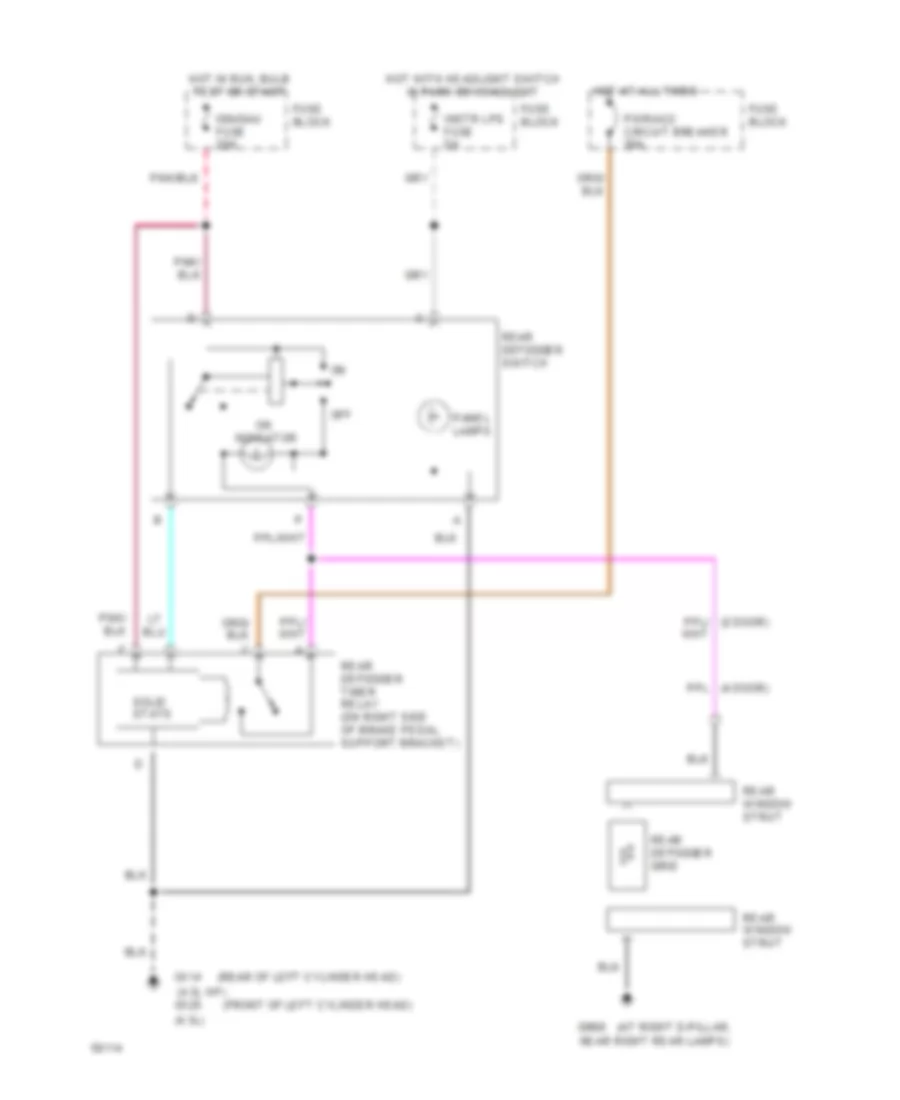
Defogger Wiring Diagram for GMC Jimmy 1994
 https://portal-diagnostov.com/license.html
Automotive Electricians Portal FZCO
Automotive Electricians Portal FZCO
https://portal-diagnostov.com/license.html
https://portal-diagnostov.com/license.html
Automotive Electricians Portal FZCO
Automotive Electricians Portal FZCOList of elements for Defogger Wiring Diagram for GMC Jimmy 1994:
- (4.3l hp)
- (4.3l)
- (at right d-pillar,
- (front of left cylinder head)
- (rear of left cylinder head)
- Fuse block
- G114
- G125
- G998
- Hot at all times
- Hot in run, bulb test or start
- Hot with headlight switch in park or headlight
- Ign/gau fuse 20a
- Indicator
- Instr lps fuse 5a
- Near right rear lamps)
- Off
- Panel lamps
- Pwr/acc circuit breaker 30a
- Rear defogger grid
- Rear defogger switch
- Rear window strut
- Rear defogger timer relay (on right side of brake pedal support bracket)
- Solid state
ENGINE PERFORMANCE
4.3L
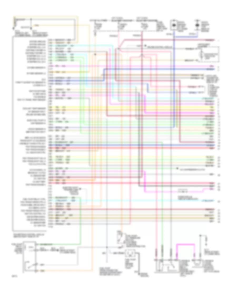
4.3L (VIN W), Engine Performance Wiring Diagrams (1 of 2) for GMC Jimmy 1994
 https://portal-diagnostov.com/license.html
Automotive Electricians Portal FZCO
Automotive Electricians Portal FZCO
https://portal-diagnostov.com/license.html
https://portal-diagnostov.com/license.html
Automotive Electricians Portal FZCO
Automotive Electricians Portal FZCOList of elements for 4.3L (VIN W), Engine Performance Wiring Diagrams (1 of 2) for GMC Jimmy 1994:
- (frame ground)
- 12v battery
- 12v ignition
- 5v return b
- 5v sensor ref
- A/c compressor clutch
- A/c on signal in
- A10
- A11
- A12
- A13
- A14
- A15
- A16
- B10
- B11
- B12
- B13
- B14
- B15
- B16
- Brake sw to pcm
- Bulb test or start
- Coolant temp sensor
- Cruise control module
- Cruise ind reg grd
- Data link connector (behind left side of i/p)
- Diode module (above fuse block)
- Distributor ref hi
- Distributor ref lo
- Dlc
- Dlc serial data
- E10
- E11
- E12
- E13
- E14
- E15
- E16
- Ecmb fuse 15a
- Ecmi fuse 10a
- Egr position input
- Egr valve solenoid
- Elec fuel pump in
- Electric shift trasfer case control module
- F10
- F11
- F12
- F13
- F14
- F15
- F16
- Four wheel drive input
- Fuel injector (top of engine inside plenum)
- Fuel pump and sender (at fuel tank)
- Fuel pump prime connector (engine compartment on center of cowl)
- Fuel pump relay (under center of i/p)
- Fuel pump relay ctrl
- Fuel pump/ oil pressure switch (top rear of engine, near distributor)
- Fuse block (behind left side of i/p)
- G114 (rear of left cylinder head)
- G117 (rear of right cylinder head)
- Hot at all times
- Hot in run,
- Iat sensor input
- Ign/gau fuse 20a
- Ignition bypass
- Ignition control (ic)
- Instrument cluster
- Knock sensor (in left cylinder head)
- Knock sensor (top rear of engine)
- Knock sensor in
- Lo side inj a
- Malfunction indicator lamp
- Map sensor in
- Mil indicator ctrl
- Oxygen sensor hi
- Oxygen sensor lo
- Pcm to trans temp sensor
- Pcm trans force mtr hi
- Pcm trans force mtr lo
- Pcm trans range a
- Pcm trans range b
- Pcm trans range c
- Pcm trans shift sol a
- Pcm trans shift sol b
- Pnk
- Powertrain control module (behind right side of i/p)
- Red
- Stepper coil a hi
- Stepper coil a lo
- Stepper coil b hi
- Stepper coil b lo
- System ground
- Tan
- Tcc clutch ctrl
- Tcc enable
- Throttle position sensor in
- Trans shift 2/3 solenoid
- Variable tuning control relay (engine compartment, left side of cowl)
- Variable tuning control solenoid (location not available)
- Variable tuning ctrl rly
- Vss buffer signal
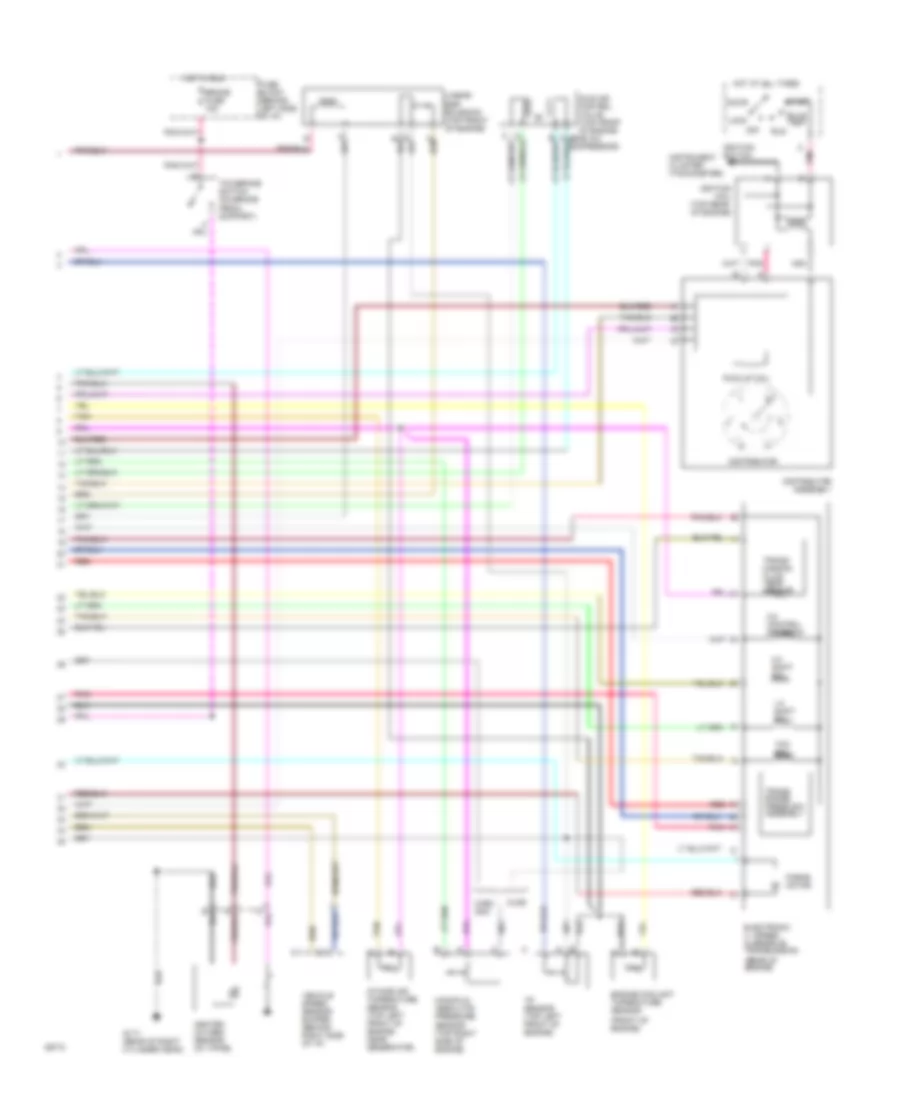
4.3L (VIN W), Engine Performance Wiring Diagrams (2 of 2) for GMC Jimmy 1994
 https://portal-diagnostov.com/license.html
Automotive Electricians Portal FZCO
Automotive Electricians Portal FZCO
https://portal-diagnostov.com/license.html
https://portal-diagnostov.com/license.html
Automotive Electricians Portal FZCO
Automotive Electricians Portal FZCOList of elements for 4.3L (VIN W), Engine Performance Wiring Diagrams (2 of 2) for GMC Jimmy 1994:
- (front of engine)
- (rear of engine)
- 1-2 shift sol
- 2-3 shift sol
- 3-2 control solenoid
- Accy
- Brake fuse 15a
- Bulb test
- C11
- C13
- Chev gmc
- Distributor
- Distributor assembly
- Electronic 4 - speed overdrive transmission
- Engine coolant tmperature sensor
- Force motor
- Fuse block (behind left side of i/p)
- G117 (rear of right cylinder head)
- Heated oxygen sensor (in y-pipe)
- Hot at all times
- Hot in run
- Idle air control valve (top front of engine
- Ignition coil (top rear of engine)
- Ignition switch
- Instrument cluster (tachometer)
- Intake air tmperature sensor (top left front of engine, near generator)
- Linear egr solenoid (top front of engine)
- Lock
- Manifold absolute pressure sensor (top right side of engine)
- Nca
- Off
- Olds
- Pick-up coil
- Pnk
- Red
- Run
- Start
- Tan
- Tcc sol
- Tcc/brake switch (on brake pedal support)
- Tp sensor (top left front of engine)
- Trans range press sw assembly
- Trans- mission fluid temp sensor
- Vehicle speed sensor buffer (behind right side of i/p)
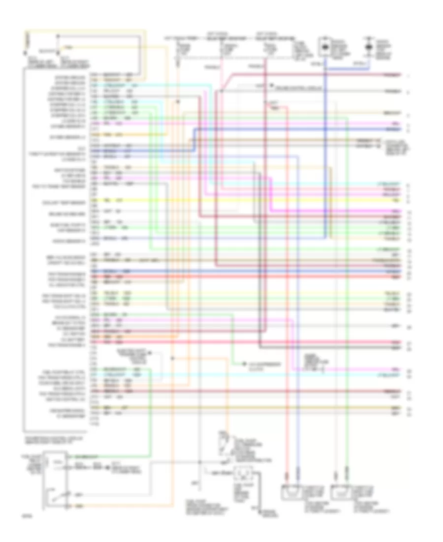
4.3L (VIN Z), Engine Performance Wiring Diagrams (1 of 2) for GMC Jimmy 1994
 https://portal-diagnostov.com/license.html
Automotive Electricians Portal FZCO
Automotive Electricians Portal FZCO
https://portal-diagnostov.com/license.html
https://portal-diagnostov.com/license.html
Automotive Electricians Portal FZCO
Automotive Electricians Portal FZCOList of elements for 4.3L (VIN Z), Engine Performance Wiring Diagrams (1 of 2) for GMC Jimmy 1994:
- (frame ground)
- 12v battery
- 12v ignition
- 5v return b
- 5v sensor ref
- A/c compressor
- A/c on signal in
- A10
- A11
- A12
- A13
- A14
- A15
- A16
- B10
- B11
- B12
- B13
- B14
- B15
- B16
- Brake sw to pcm
- Bulb test or start
- Clutch
- Coolant temp sensor
- Cruise control module
- Cruise ind reg grd
- Data link connector (behind left side of i/p)
- Diode module (above fuse block)
- Distributor ref hi
- Distributor ref lo
- Dlc
- Dlc serial data
- E10
- E11
- E12
- E13
- E14
- E15
- E16
- Ecmb fuse 15a
- Ecmi fuse 10a
- Egr valve solenoid
- Elec fuel pump in
- Electric shift trasfer case control module
- F10
- F11
- F12
- F13
- F14
- F15
- F16
- Four wheel drive input
- Fuel pump and sender (at fuel tank)
- Fuel pump prime connector (engine compartment on center of cowl)
- Fuel pump relay (under center of i/p)
- Fuel pump relay ctrl
- Fuel pump/ oil pressure switch (top rear of engine, near distributor)
- Fuse block (behind left side of i/p)
- G114 (rear of left cylinder head)
- G117 (rear of right cylinder head)
- Hot at all times
- Hot in run,
- Ign/gau fuse 20a
- Ignition bypass
- Ignition control (ic)
- Knock sensor (in left cylinder head)
- Knock sensor (top rear of engine)
- Knock sensor in
- Lo side inj a
- Lo side inj b
- Map sensor in
- Mil indicator ctrl
- Oxygen sensor hi
- Oxygen sensor lo
- Pcm to trans temp sensor
- Pcm trans force mtr hi
- Pcm trans force mtr lo
- Pcm trans range a
- Pcm trans range b
- Pcm trans range c
- Pcm trans shift sol a
- Pcm trans shift sol b
- Pnk
- Powertrain control module (behind right side of i/p)
- Red
- Stepper coil a hi
- Stepper coil a lo
- Stepper coil b hi
- Stepper coil b lo
- System ground
- Tan
- Tcc clutch ctrl
- Tcc enable
- Throttle body fuel injector #1 (top center of engine in throttle body)
- Throttle body fuel injector #2 (top center of engine in throttle body)
- Throttle position sensor in
- Upshift ind (2/3 sol)
- Vss buffer signal
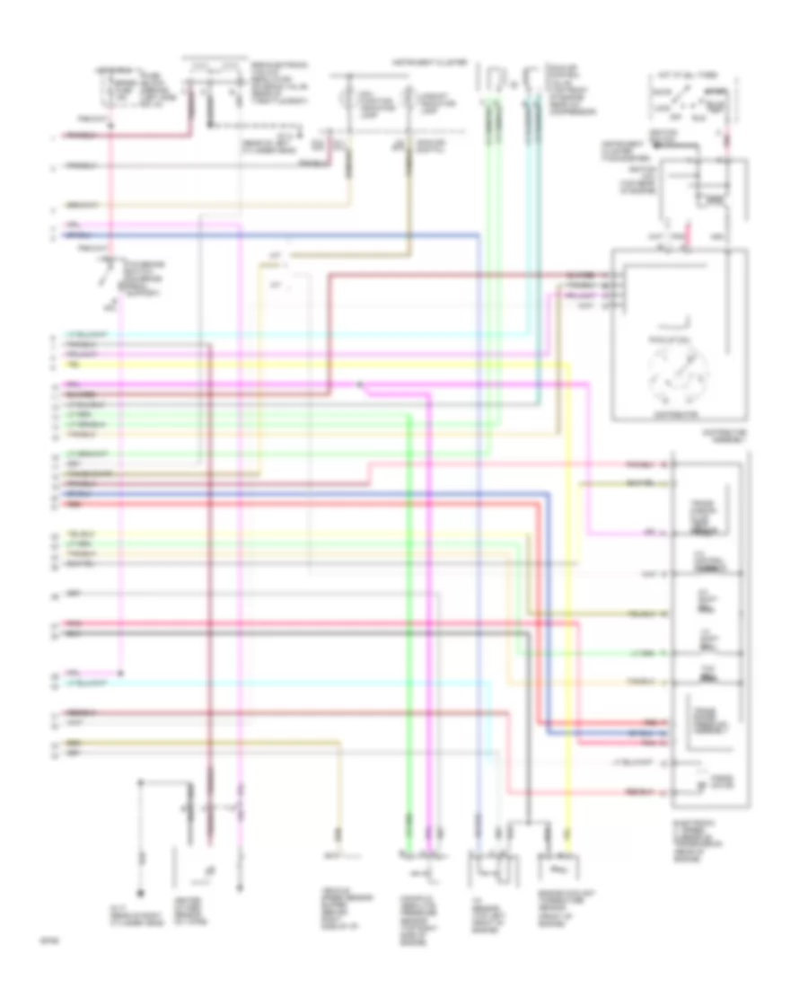
4.3L (VIN Z), Engine Performance Wiring Diagrams (2 of 2) for GMC Jimmy 1994
 https://portal-diagnostov.com/license.html
Automotive Electricians Portal FZCO
Automotive Electricians Portal FZCO
https://portal-diagnostov.com/license.html
https://portal-diagnostov.com/license.html
Automotive Electricians Portal FZCO
Automotive Electricians Portal FZCOList of elements for 4.3L (VIN Z), Engine Performance Wiring Diagrams (2 of 2) for GMC Jimmy 1994:
- (analog) (digital)
- (front of engine)
- (rear of engine)
- (rear of left cylinder head)
- 1-2 shift sol
- 2-3 shift sol
- 3-2 control solenoid
- A/t
- Accy
- Brake fuse 15a
- Bulb test
- C11
- C11 a14
- C12 a15
- C4 b15
- Distributor
- Distributor assembly
- Egr electronic vacuum regulator solenoid valve (rear of throttle body)
- Electronic 4 - speed overdrive transmission
- Engine coolant tmperature sensor
- Force motor
- Fuse block (behind left side of i/p)
- G114
- G117 (rear of right cylinder head)
- Heated oxygen sensor (in y-pipe)
- Hot at all times
- Hot in run
- Idle air control valve (top front of engine near a/c compressor)
- Ignition coil (top rear of engine)
- Ignition switch
- Instrument cluster
- Instrument cluster (tachometer)
- Lock
- M/t
- Mal- function indicator lamp
- Manifold absolute pressure sensor (top right side of engine)
- Nca
- Off
- Pick-up coil
- Pnk
- Red
- Run
- Start
- Tcc sol
- Tcc/brake switch (on brake pedal support)
- Tp sensor (top left front of engine)
- Trans range press sw assembly
- Trans- mission fluid temp sensor
- Upshift indicator lamp
- Vehicle speed sensor buffer (behind right side of i/p)
EXTERIOR LIGHTS
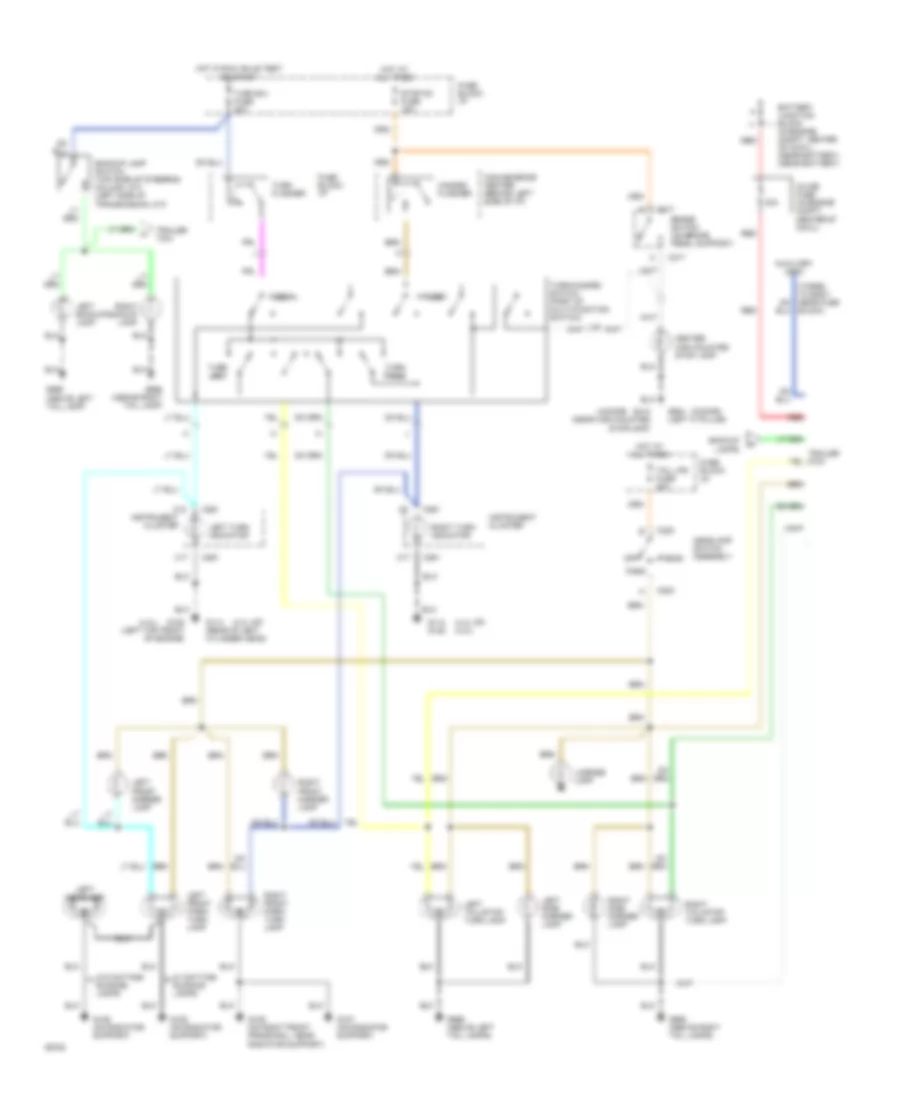
Exterior Lamps Wiring Diagram, with Analog Cluster for GMC Jimmy 1994
 https://portal-diagnostov.com/license.html
Automotive Electricians Portal FZCO
Automotive Electricians Portal FZCO
https://portal-diagnostov.com/license.html
https://portal-diagnostov.com/license.html
Automotive Electricians Portal FZCO
Automotive Electricians Portal FZCOList of elements for Exterior Lamps Wiring Diagram, with Analog Cluster for GMC Jimmy 1994:
- (2-door)
- (4-door)
- (4.3l hp)
- (4.3l hp) (4.3l)
- (4.3l)
- 30a
- Auxiliary lead
- Backup lamp switch (top side of steering column, a/t) (left side of transmission, m/t)
- Backup lamps
- Battery junction block (in engine compt, center of cowl) (near battery) (near battery)
- Block)
- Brake switch (on brake pedal support)
- C17
- C18
- C217
- C220
- C261
- Center high mounted stop lamp
- Convenience center (behind left side of i/p)
- Fuse block: i/p
- G106 (on radiator support)
- G107 (on radiator support)
- G109 (on right front frame rail, near radiator support)
- G114 (rear of left cylinder head)
- G114 g125
- G125 (left top front of engine)
- G412 (near high mounted stoplamp)
- G904 (left 'c' pillar)
- G998 (above right tail lamp)
- G998 (above right tail lamps)
- G999 (above left tail lamp)
- G999 (above left tail lamps)
- Hazard
- Hazard flasher
- Head
- Headlamp switch assembly
- Hot at all times
- Hot in run, bulb test or start
- Inline fuse (in engine compt, center of cowl)
- Instrument cluster
- Left backup lamp
- Left front marker lamp
- Left front park/ turn lamp
- Left headlamp
- Left side marker lamp
- Left tail/stop/ turn lamp
- Left turn indicator
- License lamp
- Normal
- Off
- Park
- Red
- Right backup lamp
- Right front marker lamp
- Right front park/ turn lamp
- Right side marker lamp
- Right tail/stop/ turn lamp
- Right turn indicator
- Stop-hz fuse 15a
- Tail lps fuse 20a
- Trailer tow
- Turn b/u fuse 20a
- Turn flasher
- Turn left
- Turn right
- Turn/hazard switch (part of multi-function switch)
- W/ daytime running lamps
- W/o daytime running lamps
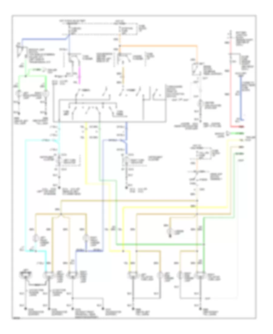
Exterior Lamps Wiring Diagram, with Digital Cluster for GMC Jimmy 1994
 https://portal-diagnostov.com/license.html
Automotive Electricians Portal FZCO
Automotive Electricians Portal FZCO
https://portal-diagnostov.com/license.html
https://portal-diagnostov.com/license.html
Automotive Electricians Portal FZCO
Automotive Electricians Portal FZCOList of elements for Exterior Lamps Wiring Diagram, with Digital Cluster for GMC Jimmy 1994:
- (2-door)
- (4-door)
- (4.3 hp) (4.3l)
- (4.3l hp)
- (4.3l hp) (4.3l)
- (4.3l)
- (taped to body near fuse block)
- 30a
- Auxiliary lead
- Backup lamp switch (top side of steering column, a/t) (left side of transmission, m/t)
- Backup lamps
- Battery junction block (engine compt, (center of cowl)
- Brake switch (on brake pedal support)
- C215
- C217
- C220
- Center high mounted stoplamp
- Convenience center (behind left side of i/p)
- Fuse block: i/p
- G106 (on radiator support)
- G107 (on radiator support)
- G109 (on right front frame rail, near radiator support)
- G114 (rear of left cylinder head)
- G114 g125
- G125 (left top front of engine)
- G412 (near high mounted stoplamp)
- G904 (left 'c" pillar)
- G998 (above right tail lamp)
- G998 (above right tail lamps)
- G999 (above left tail lamp)
- G999 (above left tail lamps)
- Hazard
- Hazard flasher
- Head
- Headlamp switch assembly
- Hot at all times
- Hot in run, bulb test or start
- Inline fuse (engine (compt, center of cowl)
- Instrument cluster
- Left backup lamp
- Left front marker lamp
- Left front park/ turn lamp
- Left headlamp
- Left side marker lamp
- Left tail/stop/ turn lamp
- Left turn indicator
- License lamp
- Normal
- Off
- Park
- Red
- Right backup lamp
- Right front marker lamp
- Right front park/ turn lamp
- Right side marker lamp
- Right tail/stop/ turn lamp
- Right turn indicator
- Stop-haz fuse 15a
- Tail lps fuse 20a
- Trailer tow
- Turn b/u fuse 20a
- Turn flasher
- Turn left
- Turn right
- Turn/hazard switch (part of mult-function switch)
- W/ daytime running lamps
- W/o daytime running lamps
GROUND DISTRIBUTION
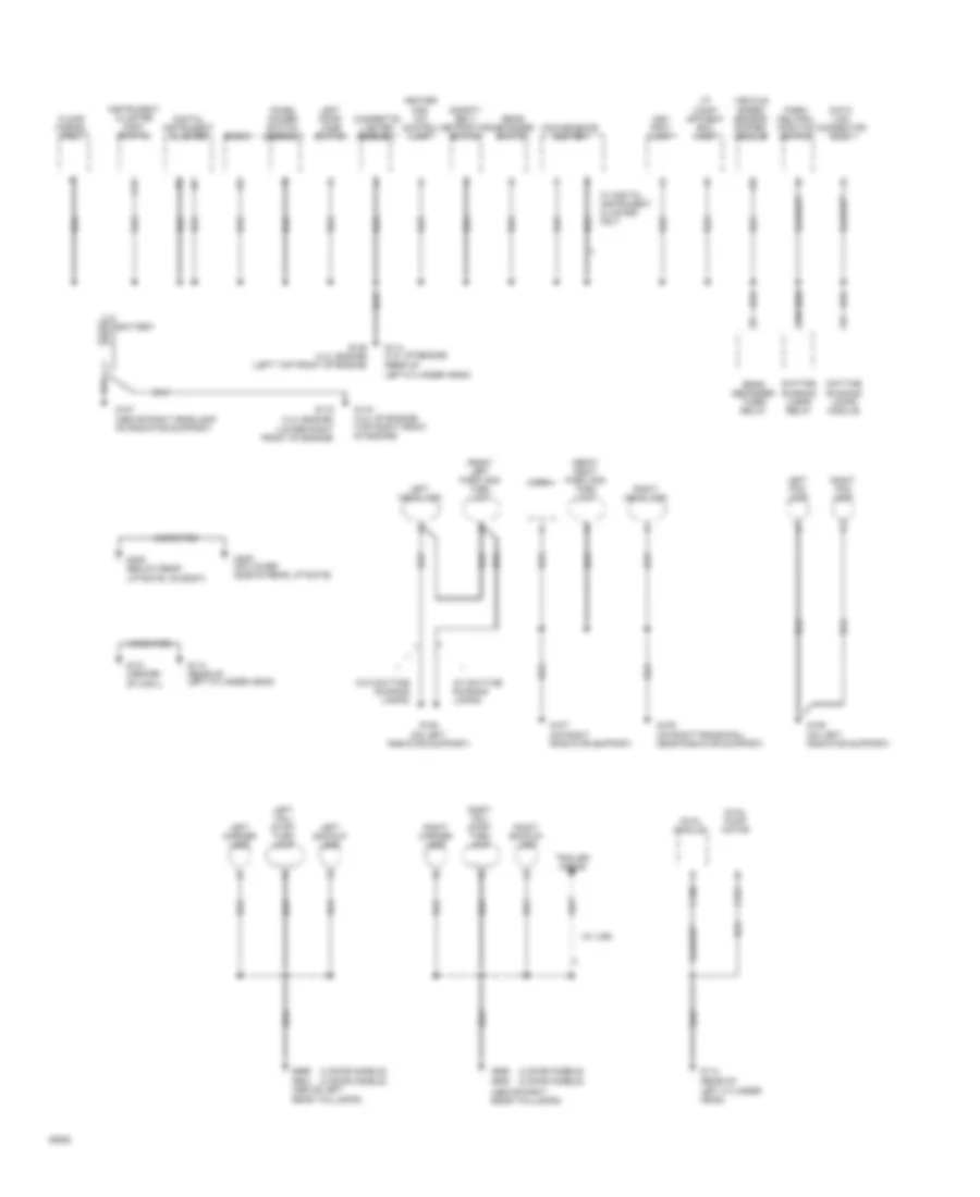
Ground Distribution Wiring Diagram (1 of 2) for GMC Jimmy 1994
 https://portal-diagnostov.com/license.html
Automotive Electricians Portal FZCO
Automotive Electricians Portal FZCO
https://portal-diagnostov.com/license.html
https://portal-diagnostov.com/license.html
Automotive Electricians Portal FZCO
Automotive Electricians Portal FZCOList of elements for Ground Distribution Wiring Diagram (1 of 2) for GMC Jimmy 1994:
- (4 door models) (2 door models)
- (4.3l engine) (lower right front of engine)
- (above right rear taillamps)
- (w/ daytime running lamps)
- (w/ u89)
- (w/o daytime running lamps)
- 4wal module
- 4wal pump motor
- Ash tray lamp
- Battery
- C150
- C151
- C17
- Cigarette lighter assembly
- Convenience center
- Data link connector (dlc)
- Daytime running lamps module
- Daytime running lamps relay
- Digital instrument cluster
- Floor parcel tray
- Front left park and turn lamp
- Front right park and turn lamp
- G106 (on left radiator support)
- G107 (above right headlamp, on radiator support)
- G107 (on right radiator support)
- G109 (on right frame rail, near radiator support)
- G114 (4.3l hp engine) (rear of left cylinder head)
- G114 (rear of left cylinder head)
- G119
- G119 (4.3l hp engine) (top right front of engine)
- G121 (center of cowl)
- G125 (4.3l engine) (left top front of engine)
- G409 (below rear liftgate, on body)
- G409 (on lower side of rear liftgate)
- G998 g905
- G999 g904 (above left rear taillamps)
- Heater and a/c control lamp
- Horn
- I/p comp- artment box lamp
- Instrument cluster (non- digital)
- Left backup lamp
- Left door jamb switch
- Left fog lamp
- Left headlamp
- Left marker lamp
- Left tail/ stop- turn lamp
- Panel dimmer switch assembly
- Park/ neutral position switch
- Radio
- Rear defogger switch
- Rear defogger timer relay
- Right backup lamp
- Right fog lamp
- Right headlamp
- Right marker lamp
- Right tail/ stop- turn lamp
- Safety belt retractor switch
- Trailer wiring
- Uncoated
- Vehicle speed sensor buffer module
- W/ digital instrument cluster only
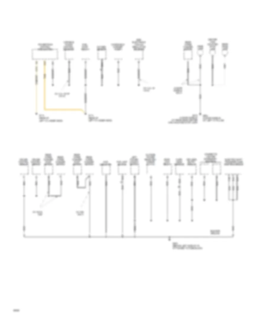
Ground Distribution Wiring Diagram (2 of 2) for GMC Jimmy 1994
 https://portal-diagnostov.com/license.html
Automotive Electricians Portal FZCO
Automotive Electricians Portal FZCO
https://portal-diagnostov.com/license.html
https://portal-diagnostov.com/license.html
Automotive Electricians Portal FZCO
Automotive Electricians Portal FZCOList of elements for Ground Distribution Wiring Diagram (2 of 2) for GMC Jimmy 1994:
- (2 door models only)
- (w/ 4.3l v6 hp vin w)
- (w/ 4.3l v6 vin z)
- (w/ c25 only)
- (w/ k34 & c25)
- 4wd indicator
- A12
- Bus bar ground
- C10
- C211
- Center high mounted stop lamp
- Cigarette lighter accessory sockets
- Cruise control module
- Cruise control servo
- D12
- D13
- Dome lamp
- Door lock relay
- Egr electronic vacuum regulator solenoid
- Electric shift transfer case control module
- Fog lamp switch
- Fuel pump relay
- G114 (rear of left cylinder head)
- G204 (behind left side of i/p, attached to fuse block)
- G412 (4 door models) (at rear near center high mounted stop lamp)
- G904 (2 door models) (at left "c" pillar)
- Keyless entry module
- Left power window switch
- Nca
- Outside power rearview- mirror switch
- Over- head console
- Oxygen sensor
- Powertrain control module (pcm)
- Rear dome lamp
- Rear wiper washer motor
- Rear wiper washer pump motor
- Rear wiper washer switch
- Tan
- Variable tuning control solenoid
- Windshield washer pump
HEADLIGHTS
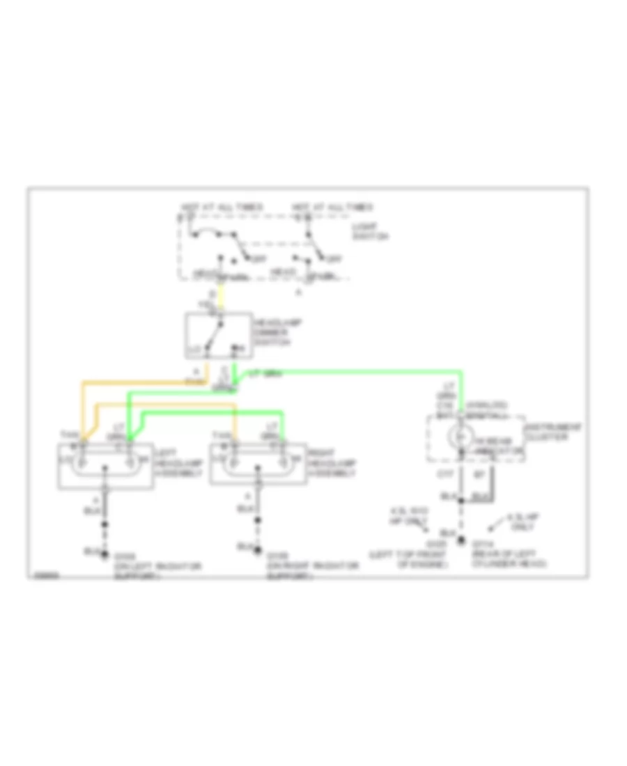
Headlamps Wiring Diagram for GMC Jimmy 1994
 https://portal-diagnostov.com/license.html
Automotive Electricians Portal FZCO
Automotive Electricians Portal FZCO
https://portal-diagnostov.com/license.html
https://portal-diagnostov.com/license.html
Automotive Electricians Portal FZCO
Automotive Electricians Portal FZCOList of elements for Headlamps Wiring Diagram for GMC Jimmy 1994:
- (analog) (digital)
- 4.3l hp only
- 4.3l w/o hp only
- C17
- G108 (on left radiator support)
- G109 (on right radiator support)
- G114 (rear of left cylinder head)
- G125 (left top front of engine)
- Head
- Headlamp dimmer switch
- Hi beam indicator
- Hot at all times
- Instrument cluster
- Left hi headlamp assembly
- Light switch
- Off
- Park
- Right hi headlamp assembly
- Tan
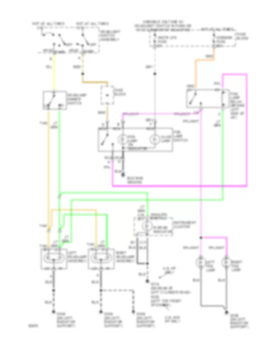
Headlamps/Fog Lamps Wiring Diagram for GMC Jimmy 1994
 https://portal-diagnostov.com/license.html
Automotive Electricians Portal FZCO
Automotive Electricians Portal FZCO
https://portal-diagnostov.com/license.html
https://portal-diagnostov.com/license.html
Automotive Electricians Portal FZCO
Automotive Electricians Portal FZCOList of elements for Headlamps/Fog Lamps Wiring Diagram for GMC Jimmy 1994:
- (analog) (digital)
- 4.3l hp only
- 4.3l w/o hp only
- B nca
- Bus bar ground
- C16 b17
- C17
- Fog lamp on indicator
- Fog lamp relay (behind left side of i/p)
- Fog lamp switch
- Fuse block
- G106 (on left radiator support)
- G109 (on left radiator support)
- G114 (on rear of left cylinder head)
- G125 (left top front of engine)
- Head
- Headlamp dimmer switch
- Headlight switch assembly
- Hi beam indicator
- Horn/dm fuse 20a
- Hot at all times
- Illum lamp
- Instr lps fuse 5a
- Instrument cluster
- Left fog lamp
- Left headlamp assembly
- Nca
- Nca g
- Off
- Park
- Right fog lamp
- Right headlamp assembly
- Tan
- Variable voltage w/ headlight switch in park or head & rheostat adjusted
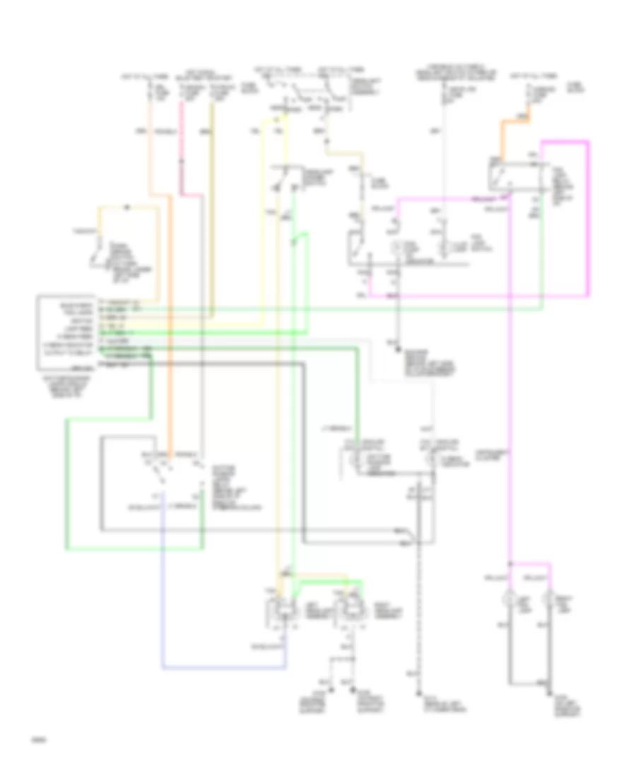
Headlamps/Fog Lamps Wiring Diagram, with DRL for GMC Jimmy 1994
 https://portal-diagnostov.com/license.html
Automotive Electricians Portal FZCO
Automotive Electricians Portal FZCO
https://portal-diagnostov.com/license.html
https://portal-diagnostov.com/license.html
Automotive Electricians Portal FZCO
Automotive Electricians Portal FZCOList of elements for Headlamps/Fog Lamps Wiring Diagram, with DRL for GMC Jimmy 1994:
- (analog) (digital)
- Bulb check
- Bulb test or start
- Bus bar ground (behind left side of i/p on steering column bracket)
- C13 b15
- C16 (analog) (digital) b17
- C17
- Daytime running lamp indicator
- Daytime running lamps module (behind left side of i/p)
- Daytime running lamps relay (behind left side of i/p right of steering column)
- Drl fuse 10a
- Fog lamp on indicator
- Fog lamp relay (behind left side of i/p)
- Fog lamp switch
- Fog lamps
- Fuse block
- G106 (on left radiator support)
- G109 (on right radiator
- G109 (on right radiator support)
- G114 (rear of left cylinder head)
- Ground
- Head
- Headlamp dimmer switch
- Headlight switch assembly
- Hi beam feed
- Hi beam indicator
- Horn/dm fuse 20a
- Hot at all times
- Hot in run,
- Htr-a/c fuse 25a
- Ign/gau fuse 20a
- Ignition
- Illum lamp
- Instr lps fuse 5a
- Instrument cluster
- Lamp feed
- Left fog lamp
- Left headlamp assembly
- Nca
- Off
- Output to relay
- Park
- Park brake switch (at park brake, under left side of i/p)
- Right fog lamp
- Right headlamp assembly
- Support)
- Tan
- Variable voltage w/ headlight switch in park or head & rheostat adjusted
HORN
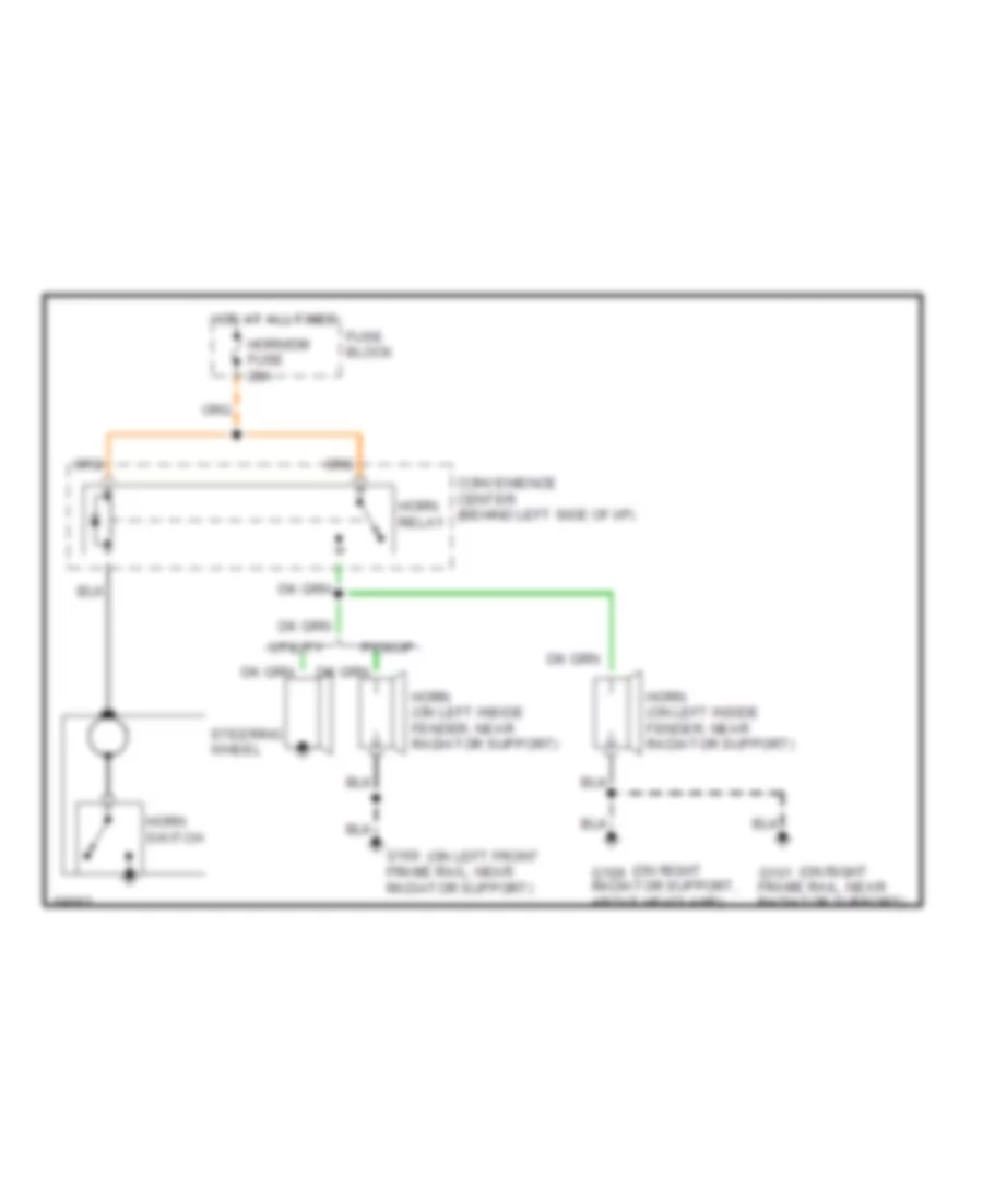
Horn Wiring Diagram for GMC Jimmy 1994
 https://portal-diagnostov.com/license.html
Automotive Electricians Portal FZCO
Automotive Electricians Portal FZCO
https://portal-diagnostov.com/license.html
https://portal-diagnostov.com/license.html
Automotive Electricians Portal FZCO
Automotive Electricians Portal FZCOList of elements for Horn Wiring Diagram for GMC Jimmy 1994:
- (on left front
- (on right
- Convenience center (behind left side of i/p)
- Fuse block
- G100 frame rail, near radiator support)
- G101 frame rail, near radiator support)
- G109 radiator support, above headlamp)
- Horn (on left inside fender, near radiator support)
- Horn relay
- Horn switch
- Horn/dm fuse 20a
- Hot at all times
- Pickup
- Steering wheel
- Utility
INSTRUMENT CLUSTER
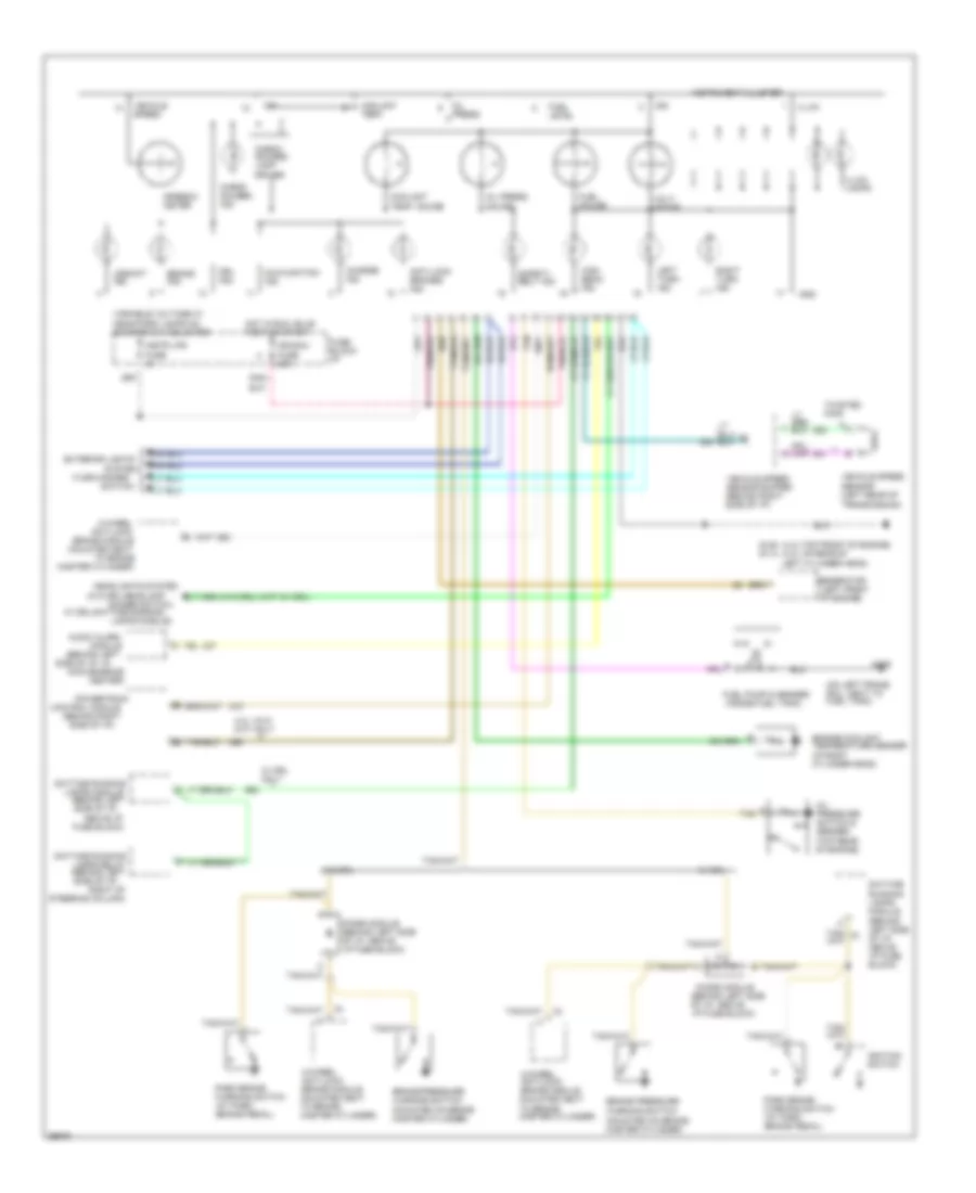
Analog Cluster Wiring Diagram for GMC Jimmy 1994
 https://portal-diagnostov.com/license.html
Automotive Electricians Portal FZCO
Automotive Electricians Portal FZCO
https://portal-diagnostov.com/license.html
https://portal-diagnostov.com/license.html
Automotive Electricians Portal FZCO
Automotive Electricians Portal FZCOList of elements for Analog Cluster Wiring Diagram for GMC Jimmy 1994:
- (4.3l-top front of engine) (4.3l hp-rear of
- (behind left
- (behind left side of i/p,
- (behind left side of i/p, above i/p fuse block)
- (behind right
- (inside fuel tank)
- (left front of engine)
- (mounted on brake master cylinder)
- (on left frame rail, next to fuel tank)
- (top rear of engine)
- (turn-hazard
- (w/o drl-headlamp
- 4-wheel
- 4-wheel anti-lock brake module (mounted next to brake master cylinder)
- 4.3l vin z (m/t) only
- Above i/p
- Anti-lock
- Anti-lock brakes ind.
- Audio alarm
- Brake ind.
- Brake module (mounted next
- Brake pressure warning switch
- Center)
- Charge ind.
- Check gauges ind.
- Check gauges lamp driver
- Control module
- Convenience
- Coolant temp.
- Coolant temp. gauge
- Daytime
- Daytime running
- Dimmer switch;
- Diode module
- Diode module (behind left side of i/p, above i/p fuse block)
- Drl ind.
- Engine coolant temperature sender (in right cylinder head)
- Exterior lights
- Fuel gauge
- Fuel level
- Fuel pump & sender
- Fuse block)
- Fuse block: i/p
- G125 g114
- G409
- Generator
- Gnd
- Headlights system
- High beam ind.
- Hot in run, bulb test or start
- Ign
- Ign/gau fuse 20a
- Ignition switch
- Illum.
- Illum. lamps
- Instr lps fuse 5a
- Instrument cluster
- Lamps module
- Lamps module)
- Lamps relay (behind left side of i/p,
- Left cylinder head)
- Left turn ind.
- Malfunction ind.
- Master cylinder)
- Module
- Oil press.
- Oil press. gauge
- Oil pressure switch & sender
- Park brake warning switch (at park brake pedal)
- Powertrain
- Right of
- Right turn ind.
- Running lamps module (behind left side of i/p, above i/p fuse block)
- Safety belt ind.
- Side of i/p)
- Side of i/p, in
- Speedo- meter
- Steering column)
- Switch)
- System
- Tan
- To brake
- Twisted pair
- Upshift ind.
- Variable voltage w/ head/park lamps on & dimmer sw adjusted
- Vehicle speed
- Vehicle speed sensor (left rear of transmission)
- Vehicle speed sensor buffer (behind right side of i/p)
- Volt- meter
- W/ drl
- W/ drl only
- W/ drl-daytime running
- W/o drl
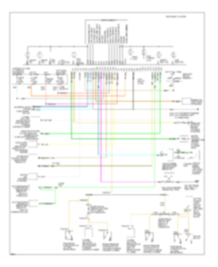
Electronic Cluster Wiring Diagram for GMC Jimmy 1994
 https://portal-diagnostov.com/license.html
Automotive Electricians Portal FZCO
Automotive Electricians Portal FZCO
https://portal-diagnostov.com/license.html
https://portal-diagnostov.com/license.html
Automotive Electricians Portal FZCO
Automotive Electricians Portal FZCOList of elements for Electronic Cluster Wiring Diagram for GMC Jimmy 1994:
- (4.3l-top front of engine) (4.3l hp-rear of left
- (behind left
- (behind left side of i/p,
- (behind right
- (inside fuel tank)
- (left front of engine)
- (mounted on brake master cylinder)
- (on left frame rail, next to fuel tank)
- (top rear of engine)
- (turn-hazard
- (w/o drl-headlamp
- 4-wheel
- 4-wheel anti-lock brake module (mounted next to brake master
- 4-wheel anti-lock brake module (mounted next to brake master cylinder)
- A10
- A11
- A12
- A13
- A14
- A15
- A16
- A17
- Above i/p
- Anti- lock brakes ind.
- Anti-lock
- Audio alarm
- B10
- B11
- B12
- B13
- B14
- B15
- B16
- B17
- Battery
- Brake fuse 15a
- Brake ind.
- Brake module (mounted next
- Brake pressure warning switch
- Center)
- Coil
- Control module
- Convenience
- Coolant temp. input
- Cylinder head)
- Cylinder)
- Daytime
- Daytime running
- Digital display
- Dimmer switch;
- Diode module (behind left side of i/p, above i/p fuse block)
- Display dim input
- Drl ind.
- Engine coolant temperature sender (in right cylinder head)
- Engine speed input
- Exterior lights
- Fuel level input
- Fuel pump & sender
- Fuse block)
- Fuse block:i/p
- G125 g114
- G409
- Generator
- Generator input
- Ground
- Head
- Headlight switch assembly
- Headlights system
- High beam ind.
- Hot at all times
- Hot in run
- Hot in run, bulb test or start
- Ign/ gau fuse 20a
- Ignition
- Ignition (run)
- Ignition (run/start)
- Ignition switch
- Illum. lamps dimming
- Instr lps fuse 5a
- Instrument cluster
- Lamps module
- Lamps module)
- Lamps relay (behind left side of i/p,
- Left turn input
- M/t only
- Mal- function ind.
- Master cylinder)
- Module
- Off
- Oil press. input
- Oil pressure switch & sender
- Park
- Park brake warning switch (at park brake pedal)
- Powertrain
- Prndl illum.
- Right of
- Right turn input
- Running lamps module (behind left side of i/p, above i/p fuse block)
- Safety belt ind.
- Side of i/p)
- Side of i/p, in
- Speed sensor (left rear of trans- mission)
- Steering column)
- Switch)
- System
- Tach warning illum.
- Tan
- To brake
- Turn b/u fuse 20a
- Twisted pair
- Upshift ind.
- Variable voltage w/ lamps on & dimmer sw adjusted
- Vehicle
- Vehicle speed input
- Vehicle speed sensor buffer (behind right side of i/p)
- W/ drl
- W/ drl only
- W/ drl-daytime running
- W/o drl
INTERIOR LIGHTS
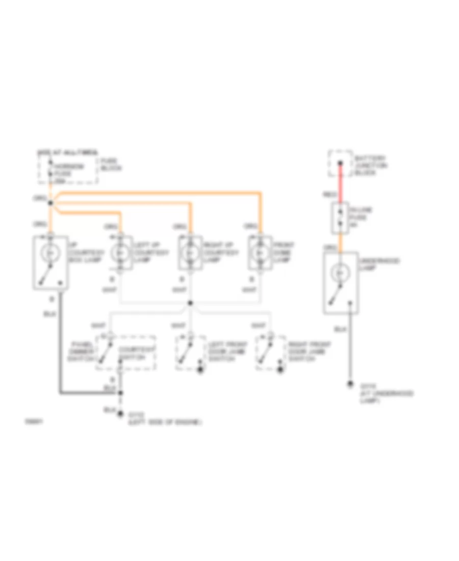
Courtesy Lamps Wiring Diagram, Base for GMC Jimmy 1994
 https://portal-diagnostov.com/license.html
Automotive Electricians Portal FZCO
Automotive Electricians Portal FZCO
https://portal-diagnostov.com/license.html
https://portal-diagnostov.com/license.html
Automotive Electricians Portal FZCO
Automotive Electricians Portal FZCOList of elements for Courtesy Lamps Wiring Diagram, Base for GMC Jimmy 1994:
- Battery junction block
- Courtesy switch
- Front dome lamp
- Fuse block
- G112 (left side of engine)
- G116 (at underhood lamp)
- Horn/dm fuse 20a
- Hot at all times
- I/p courtesy box lamp
- In line fuse 4a
- Left front door jamb switch
- Left i/p courtesy lamp
- Panel dimmer switch
- Red
- Right front door jamb switch
- Right i/p courtesy lamp
- Underhood lamp
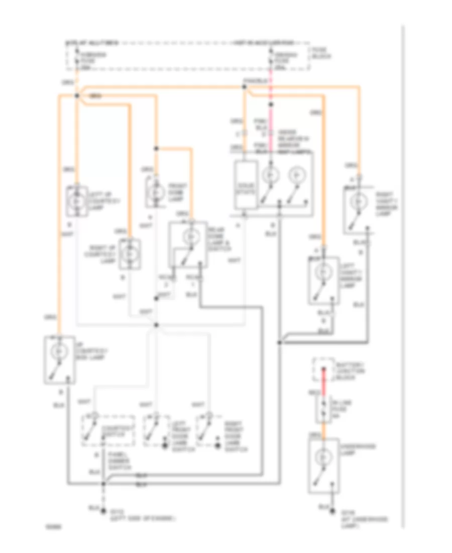
Courtesy Lamps Wiring Diagram, with Auxiliary Lighting for GMC Jimmy 1994
 https://portal-diagnostov.com/license.html
Automotive Electricians Portal FZCO
Automotive Electricians Portal FZCO
https://portal-diagnostov.com/license.html
https://portal-diagnostov.com/license.html
Automotive Electricians Portal FZCO
Automotive Electricians Portal FZCOList of elements for Courtesy Lamps Wiring Diagram, with Auxiliary Lighting for GMC Jimmy 1994:
- Battery junction block
- Courtesy switch
- Front dome lamp
- Fuse block
- G112 (left side of engine)
- G116 (at underhood lamp)
- Horn/dm fuse 20a
- Hot at all times
- Hot in accy or run
- I/p courtesy box lamp
- Ign/gau fuse 20a
- In line fuse 4a
- Inside rearview mirror map lamps
- Left front door jamb switch
- Left i/p courtesy lamp
- Left vanity mirror lamp
- Nca
- Panel dimmer switch
- Rear dome lamp & switch
- Red
- Right front door jamb switch
- Right i/p courtesy lamp
- Right vanity mirror lamp
- Solid state
- Underhood lamp
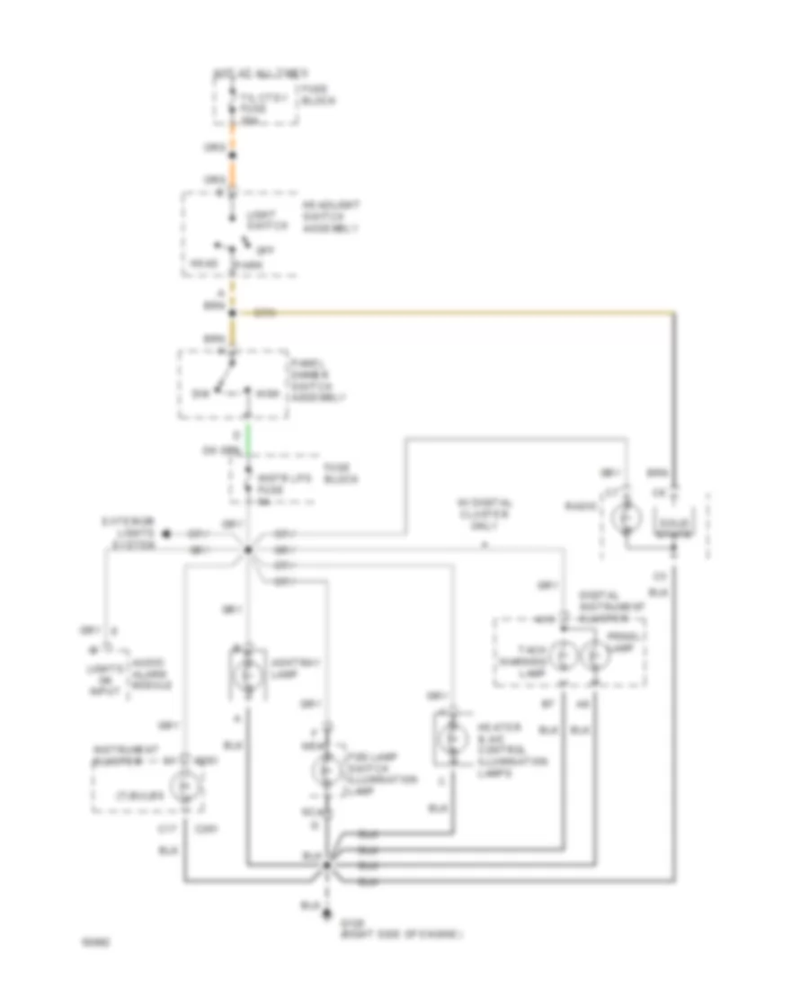
Instrument Illumination Wiring Diagram for GMC Jimmy 1994
 https://portal-diagnostov.com/license.html
Automotive Electricians Portal FZCO
Automotive Electricians Portal FZCO
https://portal-diagnostov.com/license.html
https://portal-diagnostov.com/license.html
Automotive Electricians Portal FZCO
Automotive Electricians Portal FZCOList of elements for Instrument Illumination Wiring Diagram for GMC Jimmy 1994:
- (7) bulbs
- A13
- Ashtray lamp
- Audio alarm module
- C17
- C261
- Digital instrument cluster
- Dim
- Exterior lights system
- Fog lamp switch illumination lamp
- Fuse block
- G120 (right side of engine)
- Head
- Headlight switch assembly
- Heater & a/c control illumination lamps
- High
- Hot at all times
- Instr lps fuse 5a
- Instrument cluster
- Light switch
- Lights on input
- Nca
- Off
- Panel dimmer switch assembly
- Park
- Prndl lamp
- Radio
- Solid state
- T/l ctsy fuse 20a
- Tach warning lamp
- W/ digital cluster only
POWER DISTRIBUTION
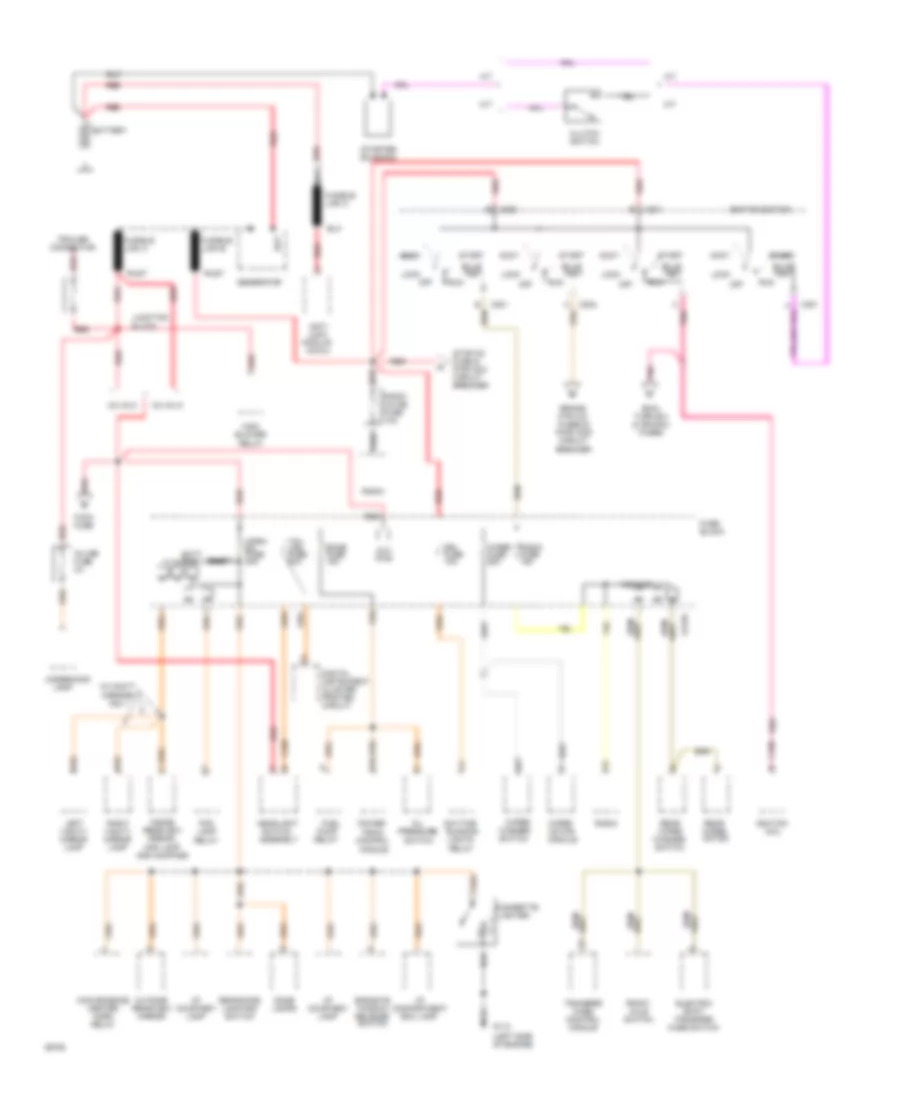
Power Distribution Wiring Diagram (1 of 3) for GMC Jimmy 1994
 https://portal-diagnostov.com/license.html
Automotive Electricians Portal FZCO
Automotive Electricians Portal FZCO
https://portal-diagnostov.com/license.html
https://portal-diagnostov.com/license.html
Automotive Electricians Portal FZCO
Automotive Electricians Portal FZCOList of elements for Power Distribution Wiring Diagram (1 of 3) for GMC Jimmy 1994:
- (left side of engine)
- A/t
- Acc bus
- Accy
- Anti- lock
- Assembly
- Aux pwr
- Bat
- Batt bus
- Battery
- Brake, htr a/c, fuses & pwr wdo circuit breaker
- Bulb test
- C185 b
- C201
- C202
- C213a
- C220 e
- Cigarette lighter
- Clutch switch
- Coil
- Control module
- Convenience center horn relay
- Daytime running
- Digital instrument cluster printed circuit
- Dome lamps
- Drl fuse 10a
- E16
- Ecmb fuse 15a
- Ecmi, turn b/u & ign/gau fuses
- Electric shift transfer case switch
- Endgate window release switch
- Fog lamp relay
- Front axle switch
- Fuel
- Fuse block
- Fusible link a
- Fusible link b
- Fusible link c
- G112
- Generator
- Headlight
- High blower relay
- Horn/ dm fuse 20a
- I/p compartment box lamp
- I/p courtesy lamp
- Ignition
- Ignition switch
- In-line fuse 4a
- Inside rearview mirror, map lamp and compass
- Junction block
- Lamp
- Left vanity mirror lamp
- Lights relay
- Lock
- M/t
- Module
- Module (4wal)
- Nca
- Off
- Oil
- Outside rearview mirror
- Pnk
- Power train
- Pressure
- Pump relay
- Radio
- Radio fuse 15a
- Radio inline fuse 10a
- Rear dome lamp and switch
- Rear wiper motor
- Rear wiper washer switch
- Red
- Right vanity mirror lamp
- Run
- Rust
- Shunt
- Start
- Starter solenoid
- Stop-hz fuse & pwr acc circuit breaker
- Switch
- Tail lps fuse 20a
- Tccm fuse
- Trailer connector
- Transfer case control module
- Underhood
- V6 vin w
- V6 vin z
- W/vanity mirrors only
- Wiper fuse 25a
- Wiper motor
- Wiper/ washer switch
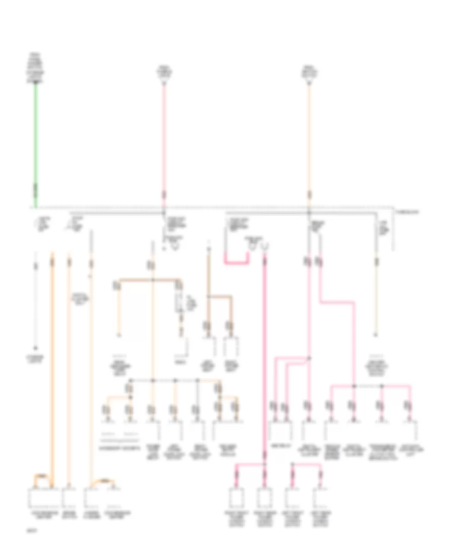
Power Distribution Wiring Diagram (2 of 3) for GMC Jimmy 1994
 https://portal-diagnostov.com/license.html
Automotive Electricians Portal FZCO
Automotive Electricians Portal FZCO
https://portal-diagnostov.com/license.html
https://portal-diagnostov.com/license.html
Automotive Electricians Portal FZCO
Automotive Electricians Portal FZCOList of elements for Power Distribution Wiring Diagram (2 of 3) for GMC Jimmy 1994:
- (interior lights system)
- Abs relay
- Accessory sockets
- Antilock controller unit
- Brake fuse 15a
- Brake switch
- Bus
- C10
- Convenience center
- Digital cluster only
- Digital instrument cluster
- From fusible link b
- From ignition switch
- From panel dimmer switch
- Fuse block
- Hazard flasher
- Heater/ heater-a/c control switch
- Htr a/c fuse 25a
- In- line fuse 10a
- Instr lps fuse 5a
- Interior lights
- Keyless entry module
- Left front power window switch
- Left power door lock switch
- Left power seat
- Left rear power window switch
- Pnk
- Power door lock relay
- Pwr acc
- Pwr acc circuit breaker 30a
- Pwr wdo
- Pwr wdo circuit breaker 30a
- Radio
- Rear defogger timer delay
- Red
- Right front power window switch
- Right power door lock switch
- Right power seat
- Right rear power window switch
- Stop- hz fuse 15a
- Transmission converter clutch (tcc) brake switch
- Vehicle speed sensor buffer
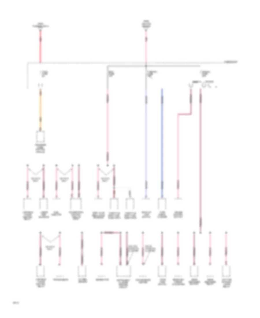
Power Distribution Wiring Diagram (3 of 3) for GMC Jimmy 1994
 https://portal-diagnostov.com/license.html
Automotive Electricians Portal FZCO
Automotive Electricians Portal FZCO
https://portal-diagnostov.com/license.html
https://portal-diagnostov.com/license.html
Automotive Electricians Portal FZCO
Automotive Electricians Portal FZCOList of elements for Power Distribution Wiring Diagram (3 of 3) for GMC Jimmy 1994:
- Back up lamp switch
- C12
- Cav e w/digital cluster
- Cluster
- Convenience center
- Cruise control switch
- Daytime running lamps relay
- Door
- E15
- Ecmi fuse 10a
- Egr valve regulator solenoid
- F15
- From fusible link a
- From ignition switch
- Fuel injector
- Fuse block
- Generator
- Ign bus
- Ign/gau fuse 20a
- Instrument cluster printed circuit
- Jamb switch
- Linear egr solenoid
- Oxygen sensor
- Pnk
- Powertrain control module (pcm)
- Rear defogger relay
- Rear defogger switch
- Rearview mirror w/compass
- Red
- Shunt
- Tccm fuse 5a
- Throttle body fuel injector a
- Throttle body fuel injector b
- Transfer case control module
- Transmission
- Turn b/u fuse 15a
- Turn signal flasher
- V6 vin w only
- V6 vin z only
- Variable tuning control relay
POWER DOOR LOCKS
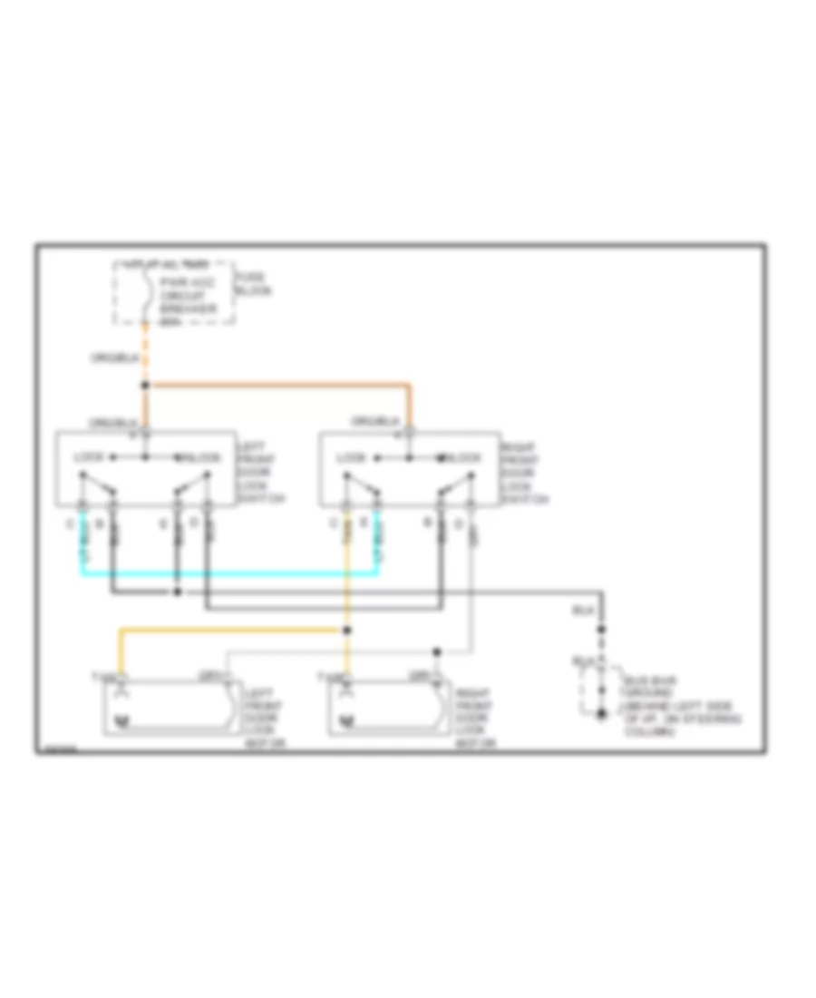
Door Lock Wiring Diagram, 2 Door for GMC Jimmy 1994
 https://portal-diagnostov.com/license.html
Automotive Electricians Portal FZCO
Automotive Electricians Portal FZCO
https://portal-diagnostov.com/license.html
https://portal-diagnostov.com/license.html
Automotive Electricians Portal FZCO
Automotive Electricians Portal FZCOList of elements for Door Lock Wiring Diagram, 2 Door for GMC Jimmy 1994:
- Bus bar ground (behind left side of i/p, on steering column)
- C tan
- Fuse block
- Hot at all times
- Left front door lock motor
- Left front door lock switch
- Lock
- Pwr acc circuit breaker 30a
- Right front door lock motor
- Right front door lock switch
- Tan
- Unlock
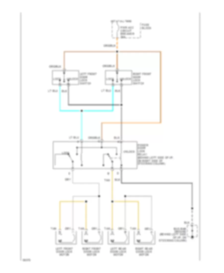
Door Lock Wiring Diagram, 4 Door for GMC Jimmy 1994
 https://portal-diagnostov.com/license.html
Automotive Electricians Portal FZCO
Automotive Electricians Portal FZCO
https://portal-diagnostov.com/license.html
https://portal-diagnostov.com/license.html
Automotive Electricians Portal FZCO
Automotive Electricians Portal FZCOList of elements for Door Lock Wiring Diagram, 4 Door for GMC Jimmy 1994:
- Bus bar ground (behind left side of i/p, on steering column)
- Fuse block
- Hot at all times
- Left front door lock motor
- Left front door lock switch
- Left rear door lock motor
- Lock
- Power door lock relay (behind left side of i/p, on right side of steering column)
- Pwr acc circuit breaker 30a
- Right front door lock motor
- Right front door lock switch
- Right rear door lock motor
- Tan
- Unlock
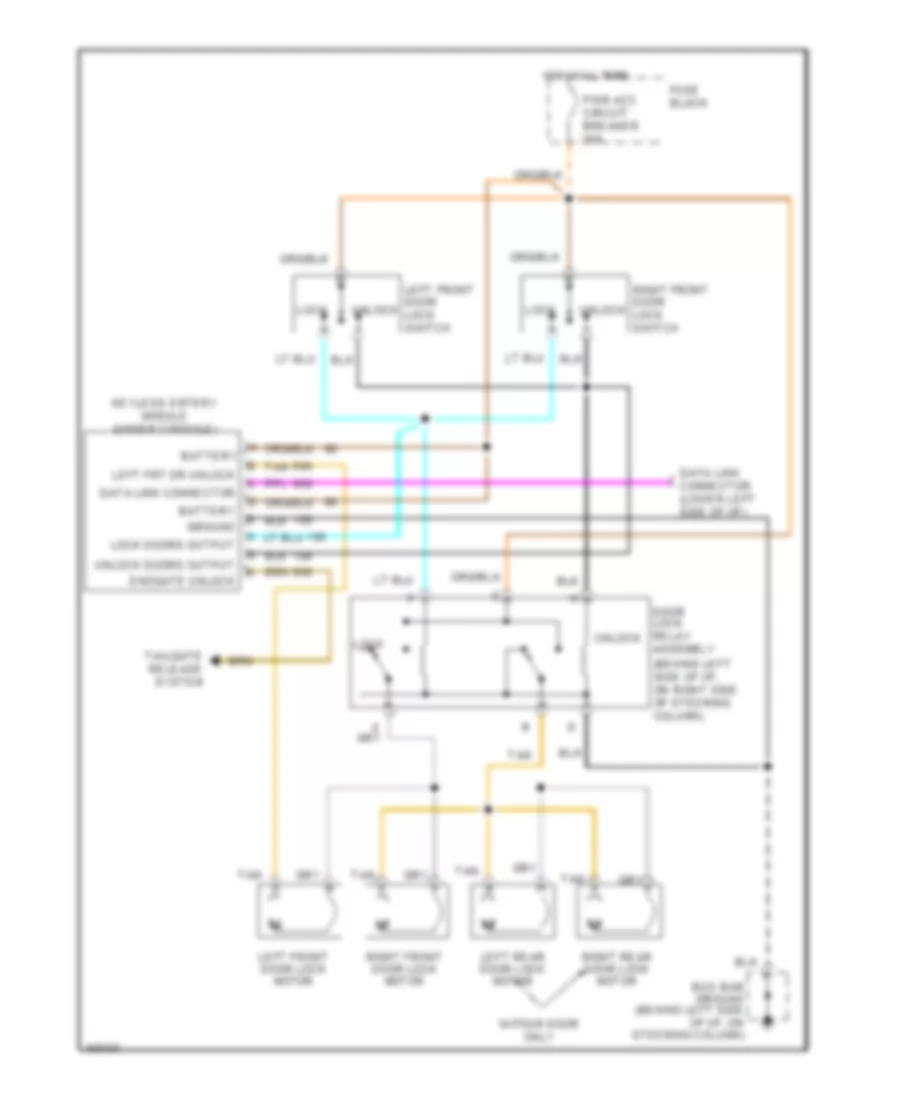
Keyless Entry Wiring Diagram for GMC Jimmy 1994
 https://portal-diagnostov.com/license.html
Automotive Electricians Portal FZCO
Automotive Electricians Portal FZCO
https://portal-diagnostov.com/license.html
https://portal-diagnostov.com/license.html
Automotive Electricians Portal FZCO
Automotive Electricians Portal FZCOList of elements for Keyless Entry Wiring Diagram for GMC Jimmy 1994:
- (behind left side of i/p, on right side of steering column)
- Battery
- Bus bar ground (behind left side of i/p, on steering column)
- Data link connector
- Data link connector (lower left side of i/p)
- Door lock relay assembly
- Endgate unlock
- Fuse block
- Ground
- Hot at all times
- Keyless entery module (under console)
- Left front door lock motor
- Left front door lock switch
- Left frt dr unlock
- Left rear door lock motor
- Lock
- Lock doors output
- Pwr acc circuit breaker 30a
- Right front door lock motor
- Right front door lock switch
- Right rear door lock motor
- Tailgate release system
- Tan
- Unlock
- Unlock doors output
- W/four door only
POWER MIRRORS
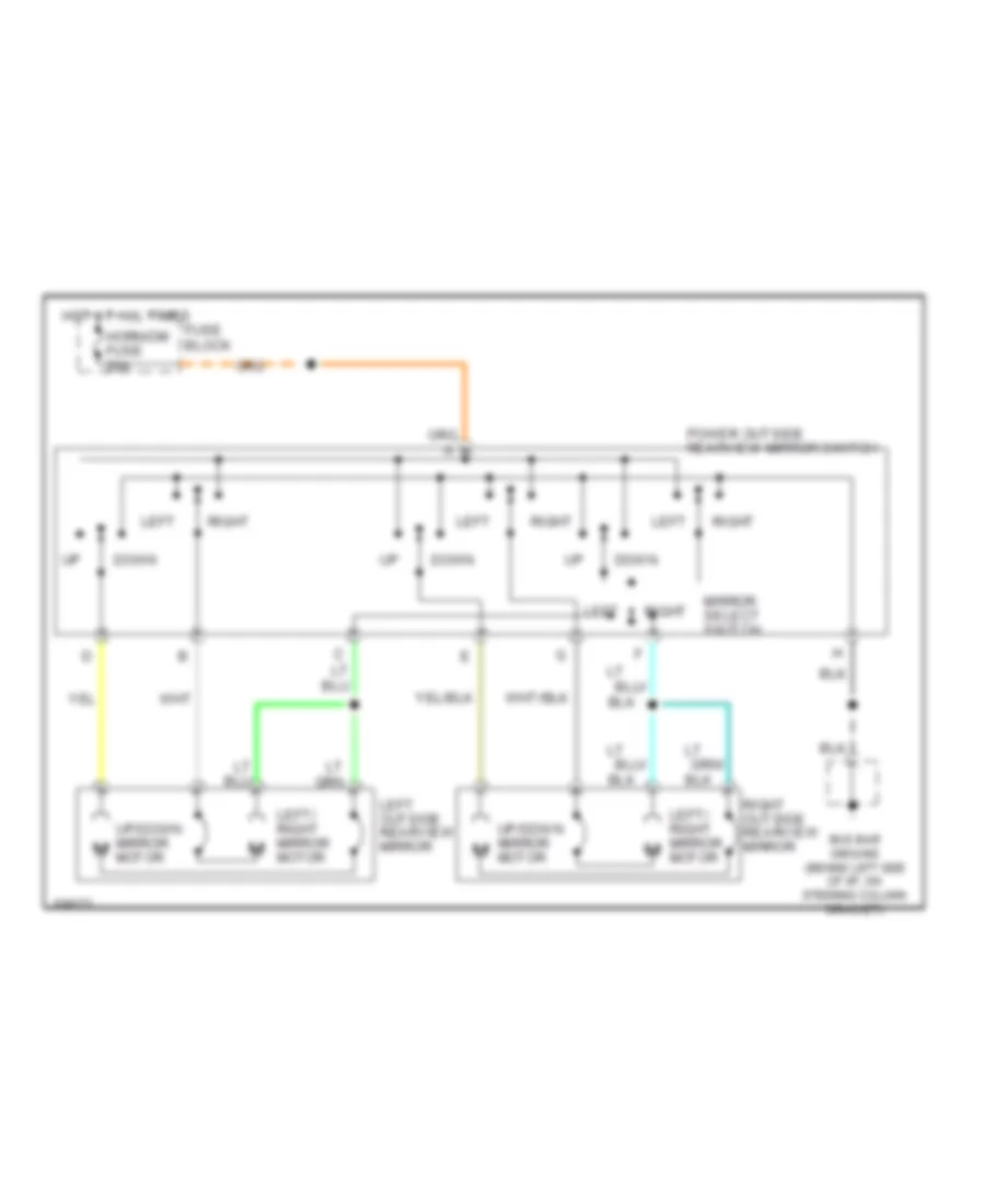
Power Mirror Wiring Diagram for GMC Jimmy 1994
 https://portal-diagnostov.com/license.html
Automotive Electricians Portal FZCO
Automotive Electricians Portal FZCO
https://portal-diagnostov.com/license.html
https://portal-diagnostov.com/license.html
Automotive Electricians Portal FZCO
Automotive Electricians Portal FZCOList of elements for Power Mirror Wiring Diagram for GMC Jimmy 1994:
-
- Bus bar ground (behind left side of i/p, on steering column bracket)
- Down
- Fuse block
- Horn/dm fuse 20a
- Hot at all times
- Left
- Left outside rearview mirror
- Left/ right mirror motor
- Mirror select switch
- Motor
- Power outside rearview mirror switch
- Right
- Right outside rearview mirror
- Up/down mirror m
- Up/down mirror motor
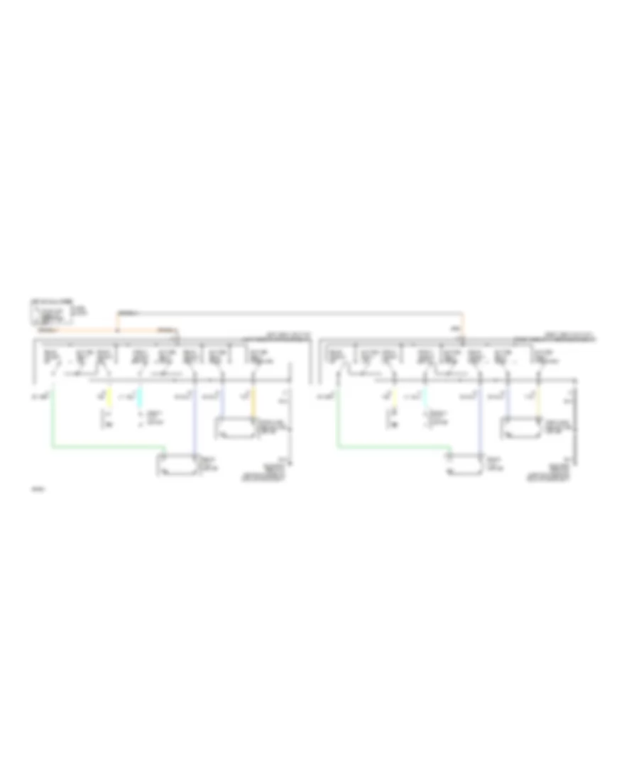
POWER SEATS
Power Seat Wiring Diagrams for GMC Jimmy 1994
 https://portal-diagnostov.com/license.html
Automotive Electricians Portal FZCO
Automotive Electricians Portal FZCO
https://portal-diagnostov.com/license.html
https://portal-diagnostov.com/license.html
Automotive Electricians Portal FZCO
Automotive Electricians Portal FZCOList of elements for Power Seat Wiring Diagrams for GMC Jimmy 1994:
- (right side of passenger's seat)
- Bus bar ground (above steering column bracket)
- D tan
- Entire seat back
- Entire seat down
- Entire seat forward
- Entire seat up
- Forward/ rearward motor
- Front height down
- Front height up
- Front tilt motor
- Fuse block
- Hot at all times
- Left seat switch (left side of driver's seat)
- Pwr acc circuit breaker 30a
- Rear height down
- Rear height up
- Rear tilt motor
- Right seat switch
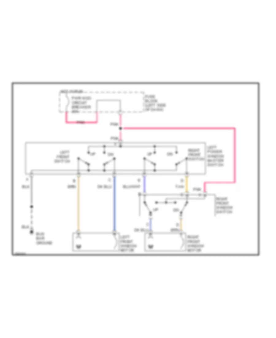
POWER WINDOWS
Power Window Wiring Diagram, 2 Door for GMC Jimmy 1994
 https://portal-diagnostov.com/license.html
Automotive Electricians Portal FZCO
Automotive Electricians Portal FZCO
https://portal-diagnostov.com/license.html
https://portal-diagnostov.com/license.html
Automotive Electricians Portal FZCO
Automotive Electricians Portal FZCOList of elements for Power Window Wiring Diagram, 2 Door for GMC Jimmy 1994:
- Bus bar ground
- Fuse block (left side of dash)
- Hot in run
- Left front switch
- Left front window motor
- Left power window master switch
- Pnk
- Pwr wdo circuit breaker 30a
- Right front switch
- Right front window motor
- Right front window switch
- Tan
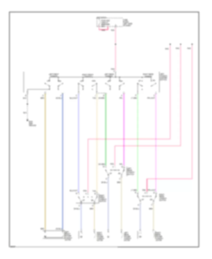
Power Window Wiring Diagram, 4 Door for GMC Jimmy 1994
 https://portal-diagnostov.com/license.html
Automotive Electricians Portal FZCO
Automotive Electricians Portal FZCO
https://portal-diagnostov.com/license.html
https://portal-diagnostov.com/license.html
Automotive Electricians Portal FZCO
Automotive Electricians Portal FZCOList of elements for Power Window Wiring Diagram, 4 Door for GMC Jimmy 1994:
- Bus bar ground
- Fuse block (left side of dash)
- Hot in run
- Left front power window motor
- Left front window
- Left rear power window motor
- Left rear window
- Left rear window switch
- Left window master switch
- Pnk
- Pwr wdo circuit breaker 30a
- Right front power window motor
- Right front window
- Right front window switch
- Right rear power window motor
- Right rear window
- Right rear window switch
- Tan
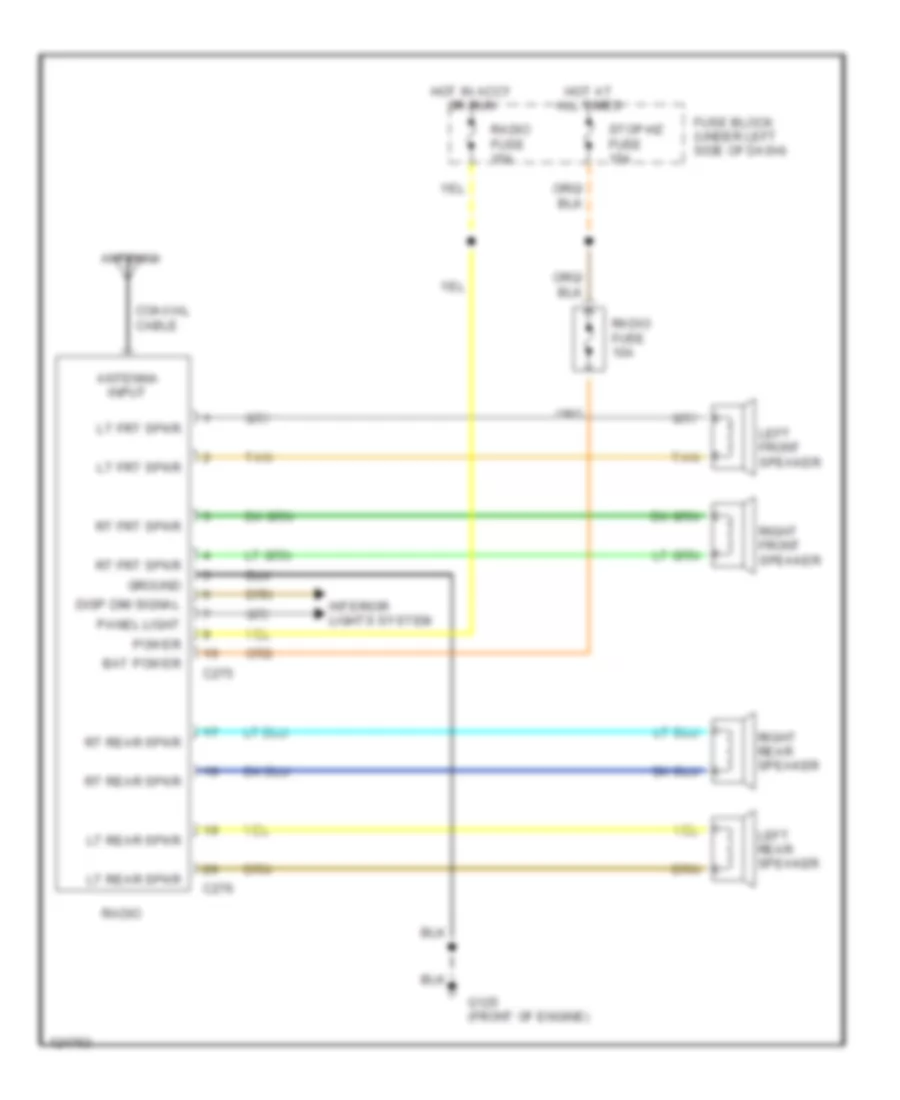
RADIO
Radio Wiring Diagrams for GMC Jimmy 1994
 https://portal-diagnostov.com/license.html
Automotive Electricians Portal FZCO
Automotive Electricians Portal FZCO
https://portal-diagnostov.com/license.html
https://portal-diagnostov.com/license.html
Automotive Electricians Portal FZCO
Automotive Electricians Portal FZCOList of elements for Radio Wiring Diagrams for GMC Jimmy 1994:
- Antenna
- Antenna input
- Bat power
- C275
- C276
- Coaxial cable
- Disp dim signal
- Fuse block (under left side of dash)
- G125 (front of engine)
- Ground
- Hot at all times
- Hot in accy or run
- Interior lights system
- Left front speaker
- Left rear speaker
- Lt frt spkr
- Lt rear spkr
- Panel light
- Power
- Radio
- Radio fuse 10a
- Radio fuse 15a
- Right front speaker
- Right rear speaker
- Rt frt spkr
- Rt rear spkr
- Stop-hz fuse 15a
- Tan
STARTING/CHARGING
4.3L
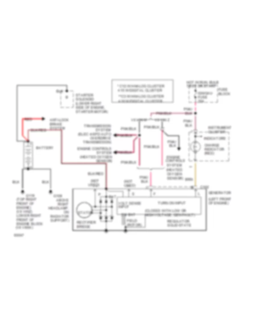
4.3L (VIN W), Charging Wiring Diagram for GMC Jimmy 1994
 https://portal-diagnostov.com/license.html
Automotive Electricians Portal FZCO
Automotive Electricians Portal FZCO
https://portal-diagnostov.com/license.html
https://portal-diagnostov.com/license.html
Automotive Electricians Portal FZCO
Automotive Electricians Portal FZCOList of elements for 4.3L (VIN W), Charging Wiring Diagram for GMC Jimmy 1994:
- (closes with low or high voltage; gen fault)
- (heated oxygen sensor)
- (left front of engine)
- (not used)
- (top right front of engine) (v6 vinz) lower right front of engine block (v6 vinw)
- * c12:w/analog cluster a15:w/digital cluster
- **c3:w/analog cluster
- A10:w/digital cluster
- Above right headlamp, on radiator support)
- Bat
- Battery
- C102
- Charge indicator (red)
- Engine controls
- Engine controls system (heated oxygen sensor)
- Field (rotor)
- Fuse block
- G109
- G119
- Generator
- Hot in run, bulb test or start
- Ign/gau fuse 20a
- Indicators
- Instrument cluster
- Rectifier bridge
- Red
- Regulator solid-state
- Starter solenoid (lower right side of engine, starter motor)
- Stator
- Sw bat
- System
- Transmission system (elec 4-spd auto overdrive transmission)
- Turn on input
- V6 vin w
- V6 vin z
- Volt sense input
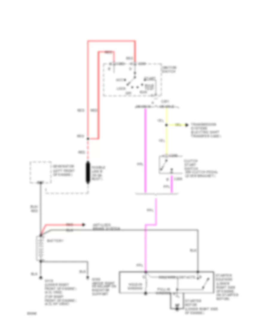
4.3L (VIN W), Starting Wiring Diagram for GMC Jimmy 1994
 https://portal-diagnostov.com/license.html
Automotive Electricians Portal FZCO
Automotive Electricians Portal FZCO
https://portal-diagnostov.com/license.html
https://portal-diagnostov.com/license.html
Automotive Electricians Portal FZCO
Automotive Electricians Portal FZCOList of elements for 4.3L (VIN W), Starting Wiring Diagram for GMC Jimmy 1994:
- (left front of engine)
- (lower right side of engine)
- (lower right side of engine, on starter motor)
- (top right front of engine) (4.3l hp vinw)
- Accy
- Anti-lock brake system
- B solenoid contacts
- Bat
- Battery
- Bulb test
- C201
- C202
- C209
- Clutch start switch (on clutch pedal lever bracket)
- Fusible link b (16 ga. rust)
- G109 above right headlamp on radiator support
- G119 (lower right front of engine) (4.3l vinz)
- Generator
- Hold-in winding
- Ignition switch
- Lock
- Off
- Pull-in winding
- Red
- Run
- Start
- Starter motor
- Starter solenoid
- Transmission systems (electric shift transfer case)
- V6 vin w
- V6 vin z
4.3L (VIN Z), Charging Wiring Diagram for GMC Jimmy 1994
 https://portal-diagnostov.com/license.html
Automotive Electricians Portal FZCO
Automotive Electricians Portal FZCO
https://portal-diagnostov.com/license.html
https://portal-diagnostov.com/license.html
Automotive Electricians Portal FZCO
Automotive Electricians Portal FZCOList of elements for 4.3L (VIN Z), Charging Wiring Diagram for GMC Jimmy 1994:
- (closes with low or high voltage; gen fault)
- (heated oxygen sensor)
- (left front of engine)
- (not used)
- (top right front of engine) (v6 vinz) lower right front of engine block (v6 vinw)
- * c12:w/analog cluster a15:w/digital cluster
- **c3:w/analog cluster
- A10:w/digital cluster
- Above right headlamp, on radiator support)
- Bat
- Battery
- C102
- Charge indicator (red)
- Engine controls
- Engine controls system (heated oxygen sensor)
- Field (rotor)
- Fuse block
- G109
- G119
- Generator
- Hot in run, bulb test or start
- Ign/gau fuse 20a
- Indicators
- Instrument cluster
- Rectifier bridge
- Red
- Regulator solid-state
- Starter solenoid (lower right side of engine, starter motor)
- Stator
- Sw bat
- System
- Transmission system (elec 4-spd auto overdrive transmission)
- Turn on input
- V6 vin w
- V6 vin z
- Volt sense input
4.3L (VIN Z), Starting Wiring Diagram for GMC Jimmy 1994
 https://portal-diagnostov.com/license.html
Automotive Electricians Portal FZCO
Automotive Electricians Portal FZCO
https://portal-diagnostov.com/license.html
https://portal-diagnostov.com/license.html
Automotive Electricians Portal FZCO
Automotive Electricians Portal FZCOList of elements for 4.3L (VIN Z), Starting Wiring Diagram for GMC Jimmy 1994:
- (left front of engine)
- (lower right side of engine)
- (lower right side of engine, on starter motor)
- (top right front of engine) (4.3l hp vinw)
- Accy
- Anti-lock brake system
- B solenoid contacts
- Bat
- Battery
- Bulb test
- C201
- C202
- C209
- Clutch start switch (on clutch pedal lever bracket)
- Fusible link b (16 ga. rust)
- G109 above right headlamp on radiator support
- G119 (lower right front of engine) (4.3l vinz)
- Generator
- Hold-in winding
- Ignition switch
- Lock
- Off
- Pull-in winding
- Red
- Run
- Start
- Starter motor
- Starter solenoid
- Transmission systems (electric shift transfer case)
- V6 vin w
- V6 vin z
TRANSMISSION
4.3L
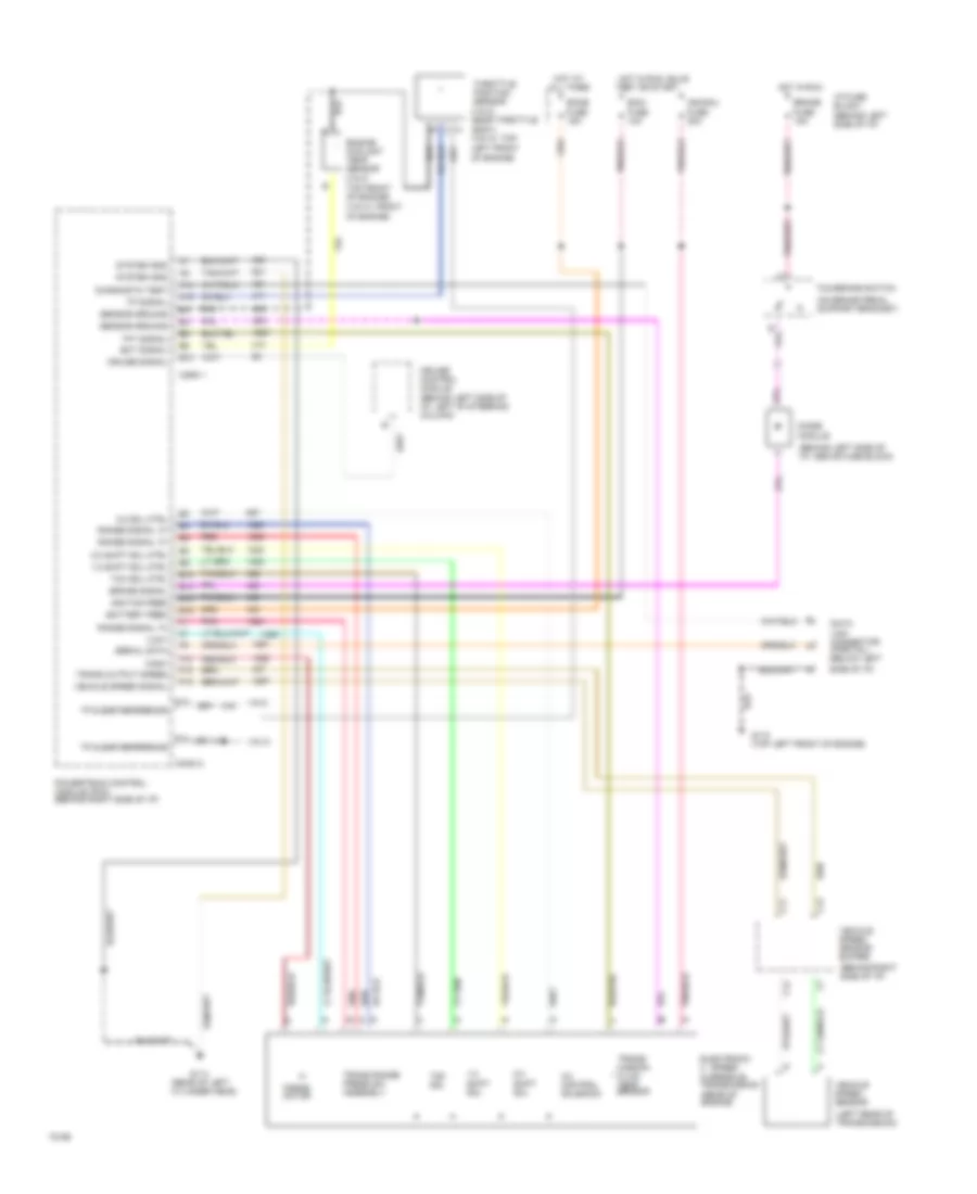
4.3L (VIN W), Transmission Wiring Diagram, 4L60-E for GMC Jimmy 1994
 https://portal-diagnostov.com/license.html
Automotive Electricians Portal FZCO
Automotive Electricians Portal FZCO
https://portal-diagnostov.com/license.html
https://portal-diagnostov.com/license.html
Automotive Electricians Portal FZCO
Automotive Electricians Portal FZCOList of elements for 4.3L (VIN W), Transmission Wiring Diagram, 4L60-E for GMC Jimmy 1994:
- "high"
- "low"
- (behind left side of i/p, above fuse block)
- (behind left side of i/p)
- (behind left side of i/p, left of steering column)
- (behind right side of i/p)
- (left rear of transmission)
- (on brake pedal support bracket)
- (rear of engine)
- (rear of left cylinder head)
- (vin w: front of engine)
- (vin z:
- (vin z: near throttle body) (vin w: top
- 1-2 shift sol
- 1-2 shift sol ctrl
- 2-3 shift sol
- 2-3 shift sol ctrl
- 3-2 control solenoid
- 3-2 sol ctrl
- A14
- A15
- B10
- Battery feed
- Brake
- Brake signal
- C11
- C12
- C13
- Conn 1
- Conn 2
- Cruise control module
- Cruise signal
- Data link connector (partial) (below left
- Diagnostic test
- Diode module
- E10
- E13
- E15
- E16
- Ecmb
- Ecmi fuse 10a
- Ect signal
- Electronic 4 - speed overdrive transmission
- Engine coolant temp sensor
- F10
- F12
- F13
- F14
- Force motor
- Fuse 15a
- Fuse 20a
- G110 (top left front of engine)
- G114
- Hot at all times
- Hot in run
- Hot in run, bulb
- I/p fuse block
- Ign/gau
- Ignition feed
- Left front of engine)
- Pnk
- Powertrain control module (pcm) (behind right side of i/p)
- Range signal "a"
- Range signal "c"
- Red
- Sensor ground
- Serial data
- Side of i/p)
- System gnd
- Tcc sol
- Tcc sol ctrl
- Tcc/brake switch
- Test or start
- Tft signal
- Throttle position sensor
- Top front of engine)
- Tp & egr reference
- Tp signal
- Trans output speed
- Trans range press sw assembly
- Trans- mission fluid temp sensor
- Vehicle speed sensor
- Vehicle speed sensor buffer
- Vehicle speed signal
- Vin w
- Vin z
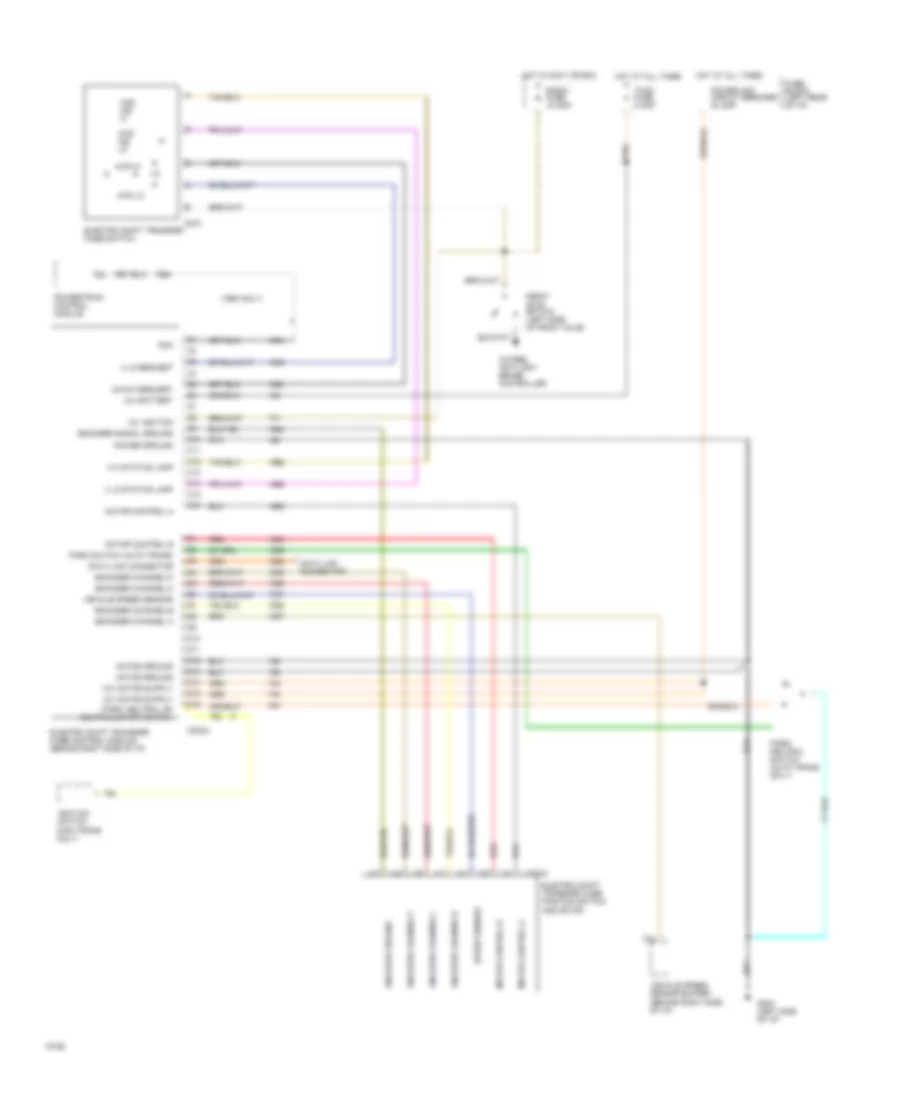
4.3L (VIN Z), Transmission Wiring Diagram, 4L60-E for GMC Jimmy 1994
 https://portal-diagnostov.com/license.html
Automotive Electricians Portal FZCO
Automotive Electricians Portal FZCO
https://portal-diagnostov.com/license.html
https://portal-diagnostov.com/license.html
Automotive Electricians Portal FZCO
Automotive Electricians Portal FZCOList of elements for 4.3L (VIN Z), Transmission Wiring Diagram, 4L60-E for GMC Jimmy 1994:
- "high"
- "low"
- (behind left side of i/p, above fuse block)
- (behind left side of i/p)
- (behind left side of i/p, left of steering column)
- (behind right side of i/p)
- (left rear of transmission)
- (on brake pedal support bracket)
- (rear of engine)
- (rear of left cylinder head)
- (vin w: front of engine)
- (vin z:
- (vin z: near throttle body) (vin w: top
- 1-2 shift sol
- 1-2 shift sol ctrl
- 2-3 shift sol
- 2-3 shift sol ctrl
- 3-2 control solenoid
- 3-2 sol ctrl
- A14
- A15
- B10
- Battery feed
- Brake
- Brake signal
- C11
- C12
- C13
- Conn 1
- Conn 2
- Cruise control module
- Cruise signal
- Data link connector (partial) (below left
- Diagnostic test
- Diode module
- E10
- E13
- E15
- E16
- Ecmb
- Ecmi fuse 10a
- Ect signal
- Electronic 4 - speed overdrive transmission
- Engine coolant temp sensor
- F10
- F12
- F13
- F14
- Force motor
- Fuse 15a
- Fuse 20a
- G110 (top left front of engine)
- G114
- Hot at all times
- Hot in run
- Hot in run, bulb
- I/p fuse block
- Ign/gau
- Ignition feed
- Left front of engine)
- Pnk
- Powertrain control module (pcm) (behind right side of i/p)
- Range signal "a"
- Range signal "c"
- Red
- Sensor ground
- Serial data
- Side of i/p)
- System gnd
- Tcc sol
- Tcc sol ctrl
- Tcc/brake switch
- Test or start
- Tft signal
- Throttle position sensor
- Top front of engine)
- Tp & egr reference
- Tp signal
- Trans output speed
- Trans range press sw assembly
- Trans- mission fluid temp sensor
- Vehicle speed sensor
- Vehicle speed sensor buffer
- Vehicle speed signal
- Vin w
- Vin z
Transfer Case Wiring Diagram for GMC Jimmy 1994
 https://portal-diagnostov.com/license.html
Automotive Electricians Portal FZCO
Automotive Electricians Portal FZCO
https://portal-diagnostov.com/license.html
https://portal-diagnostov.com/license.html
Automotive Electricians Portal FZCO
Automotive Electricians Portal FZCOList of elements for Transfer Case Wiring Diagram for GMC Jimmy 1994:
- (1994 only)
- 12v battery
- 12v ignition
- 2hi/4hi request
- 4 hi status lamp
- 4 lo request
- 4 lo status lamp
- 4wd hi
- 4wd ind hi
- 4wd ind lo
- 4wd lo
- 4wheel anti-lock brake controller
- C10
- C11
- C12
- C13
- C14
- C15
- C16
- C202a
- C273
- C374a
- D10
- D11
- D12
- D13
- D14
- D15
- D16
- Data link connector
- Electric shift transfer case position switch and motor
- Electric shift transfer case control module (behind right side of i/p)
- Electric shift transfer case switch
- Encoder channel a
- Encoder channel b
- Encoder channel c
- Encoder channel p
- Encoder channel-b
- Encoder channel-c
- Encoder channel-p
- Encoder ground
- Encoder signal ground
- Front axle switch (left side of front axle)
- Fuse block (left rear of i/p)
- G202 (left side of i/p)
- Hot at all times
- Hot in accy or run
- Ignition switch (man trans only)
- Motor control a
- Motor control b
- Motor ground
- Park switch (auto trans)
- Park/ neutral or neutral/start switch
- Park/ neutral switch (auto trans only)
- Pcm
- Power acc circuit breaker 30 amp
- Power ground
- Powertrain control module
- Radio fuse 15 amp
- Red
- Speed sensor
- Tccm fuse 5 amp
- Vehicle speed sensor
- Vehicle speed sensor buffer (behind right side of i/p)
TRUNK, TAILGATE, FUEL DOOR
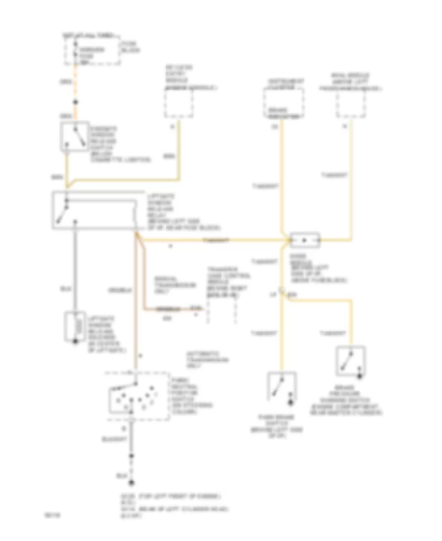
Tailgate Release Wiring Diagram for GMC Jimmy 1994
 https://portal-diagnostov.com/license.html
Automotive Electricians Portal FZCO
Automotive Electricians Portal FZCO
https://portal-diagnostov.com/license.html
https://portal-diagnostov.com/license.html
Automotive Electricians Portal FZCO
Automotive Electricians Portal FZCOList of elements for Tailgate Release Wiring Diagram for GMC Jimmy 1994:
- (rear of left cylinder head)
- (top left front of engine)
- (under console)
- 4wal module (above left
- Automatic transmission only
- B/h
- Brake pressure warning switch (engine compartment, near master cylinder)
- Brake indicator
- D16
- Diode module (behind left side of i/p, above fuseblock)
- Endgate window release switch (below cigarette lighter)
- Front wheelhouse)
- Fuse block
- G125 (4.3l) g114 (4.3 hp)
- Horn/dm fuse 20a
- Hot at all times
- Instrument cluster
- Keyless entry module
- Liftgate window release relay (behind left side of i/p, near fuse block)
- Liftgate window release solenoid (in center of liftgate)
- Manual transmission only
- Park brake switch (behind left side of i/p)
- Park/ neutral position switch (on steering column)
- Transfer case control module (behind right side of i/p)
WARNING SYSTEMS
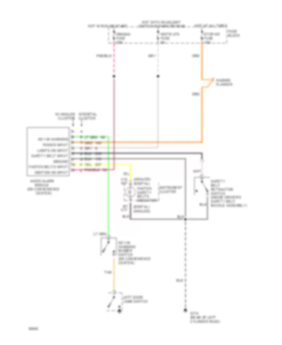
Warning System Wiring Diagrams for GMC Jimmy 1994
 https://portal-diagnostov.com/license.html
Automotive Electricians Portal FZCO
Automotive Electricians Portal FZCO
https://portal-diagnostov.com/license.html
https://portal-diagnostov.com/license.html
Automotive Electricians Portal FZCO
Automotive Electricians Portal FZCOList of elements for Warning System Wiring Diagrams for GMC Jimmy 1994:
- (analog) (digital)
- (digital) (analog)
- Audio alarm module (on convenience center)
- B7 c17
- C15 a17
- Cluster
- Fasten belts input
- Fasten safety belts indicator
- Fuse block
- G114 (rear of left cylinder head)
- Ground
- Hazard flasher
- Hot at all times
- Hot in run or start
- Hot with headlight switch in park or head
- Ign/gau fuse 20a
- Ignition on input
- Instr lps fuse 5a
- Instrument cluster
- Key-in warning
- Key-in warning buzzer switch (on convenience center)
- Left door jamb switch
- Lights on input
- Power input
- Safety belt input
- Safety belt retractor switch (inside driver's safety belt buckle assembly)
- Stop-hz fuse 15a
- Tan
- W/digital w/ analog cluster
WIPER/WASHER
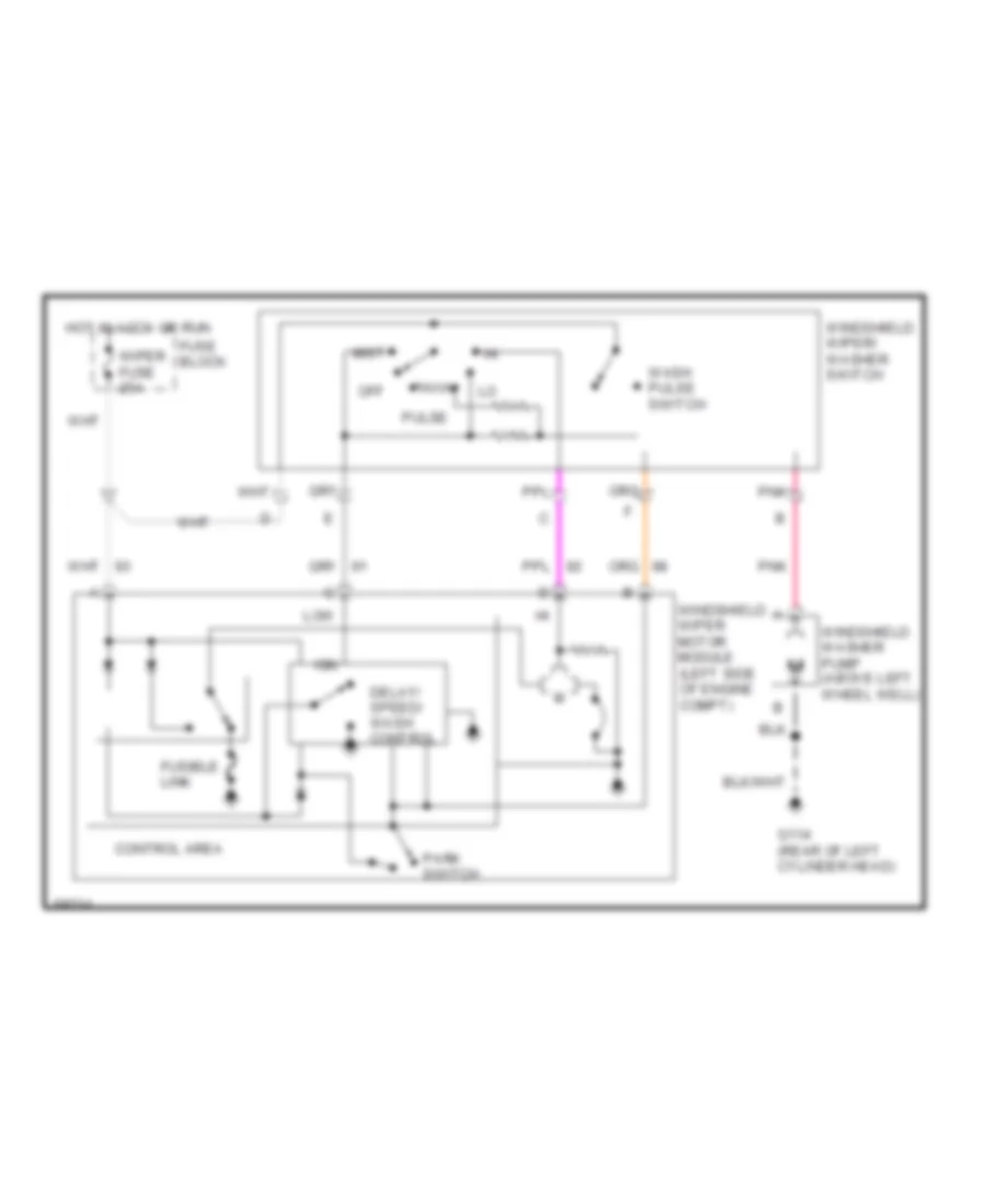
Front Wiper/Washer Wiring Diagram for GMC Jimmy 1994
 https://portal-diagnostov.com/license.html
Automotive Electricians Portal FZCO
Automotive Electricians Portal FZCO
https://portal-diagnostov.com/license.html
https://portal-diagnostov.com/license.html
Automotive Electricians Portal FZCO
Automotive Electricians Portal FZCOList of elements for Front Wiper/Washer Wiring Diagram for GMC Jimmy 1994:
- Control area
- Delay/ speed/ wash control
- Fuse block
- Fusible link
- G114 (rear of left cylinder head)
- Hot in accy or run
- Ign
- Low
- Mist
- Off
- Park switch
- Pnk
- Pulse
- Wash pulse switch
- Windshield washer pump (above left wheel well)
- Windshield wiper motor module (left side of engine compt)
- Windshield wiper/ washer switch
- Wiper fuse 25a
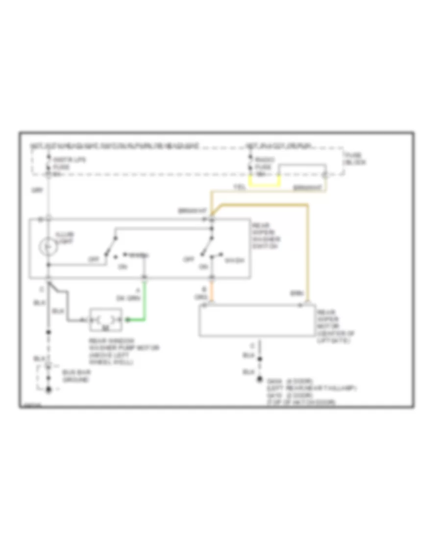
Rear Wiper/Washer Wiring Diagram for GMC Jimmy 1994
 https://portal-diagnostov.com/license.html
Automotive Electricians Portal FZCO
Automotive Electricians Portal FZCO
https://portal-diagnostov.com/license.html
https://portal-diagnostov.com/license.html
Automotive Electricians Portal FZCO
Automotive Electricians Portal FZCOList of elements for Rear Wiper/Washer Wiring Diagram for GMC Jimmy 1994:
- (2 door)
- (4 door)
- Bus bar ground
- Fuse block
- G404 (left rear,near taillamp) g410 (top of hatch door)
- Hot in accy or run
- Hot with headlight switch in park or headlight
- Illum light
- Instr lps fuse 5a
- Off
- Radio fuse 15a
- Rear window washer pump motor (above left wheel well)
- Rear wiper motor (center of liftgate)
- Rear wiper/ washer switch
- Wash

 Čeština
 Dansk
Dansk Deutsch
 Ελληνικά
 English
 English
 Español
 Suomi
Suomi Français
 Français
 עברית
עברית Hrvatski
 Magyar
 Italiano
 한국어
한국어 Nederlands
 Polski
 Português
 Português
 Română
 Русский
 Slovenčina
 Slovenščina
 Svenska
 Türkçe
 中文 (中国)
