AIR CONDITIONING
Compressor Wiring Diagram for GMC Sonoma 2004
 https://portal-diagnostov.com/license.html
Automotive Electricians Portal FZCO
Automotive Electricians Portal FZCO
https://portal-diagnostov.com/license.html
https://portal-diagnostov.com/license.html
Automotive Electricians Portal FZCO
Automotive Electricians Portal FZCO
List of elements for Compressor Wiring Diagram for GMC Sonoma 2004:
- (engine harness, between breakouts to rear heated oxygen sensors connector & body harness connector, 7 cm from breakout to heated oxygen sensor connector) s106
- (rear of right cylinder head) g102
- (rear of right cylinder head) g103
- A/c
- A/c comp rly ctrl
- A/c compressor clutch
- A/c compressor clutch diode
- A/c compressor clutch relay
- A/c fuse 10a
- A/c high pressure switch (on rear of a/c compressor)
- A/c low pressure switch (at a/c accumulator)
- A/c low sw signal
- A/c request signal
- Bi-level a/c
- Blend
- D12
- Defrost
- Heat
- Hot at all times
- Hot in run
- Hot in run & start
- Hvac control assembly
- Hvac fuse 9 20a
- I/p fuse block (on left end of dash)
- Ign e fuse 10a
- Max a/c
- Nca
- Off
- Powertrain control module (pcm) (on right side of engine compartment)
- S103 (engine harn, 19.5 cm from throttle position sensor)
- Underhood fuse block (on top of left front inner wheelwell)
- Vent
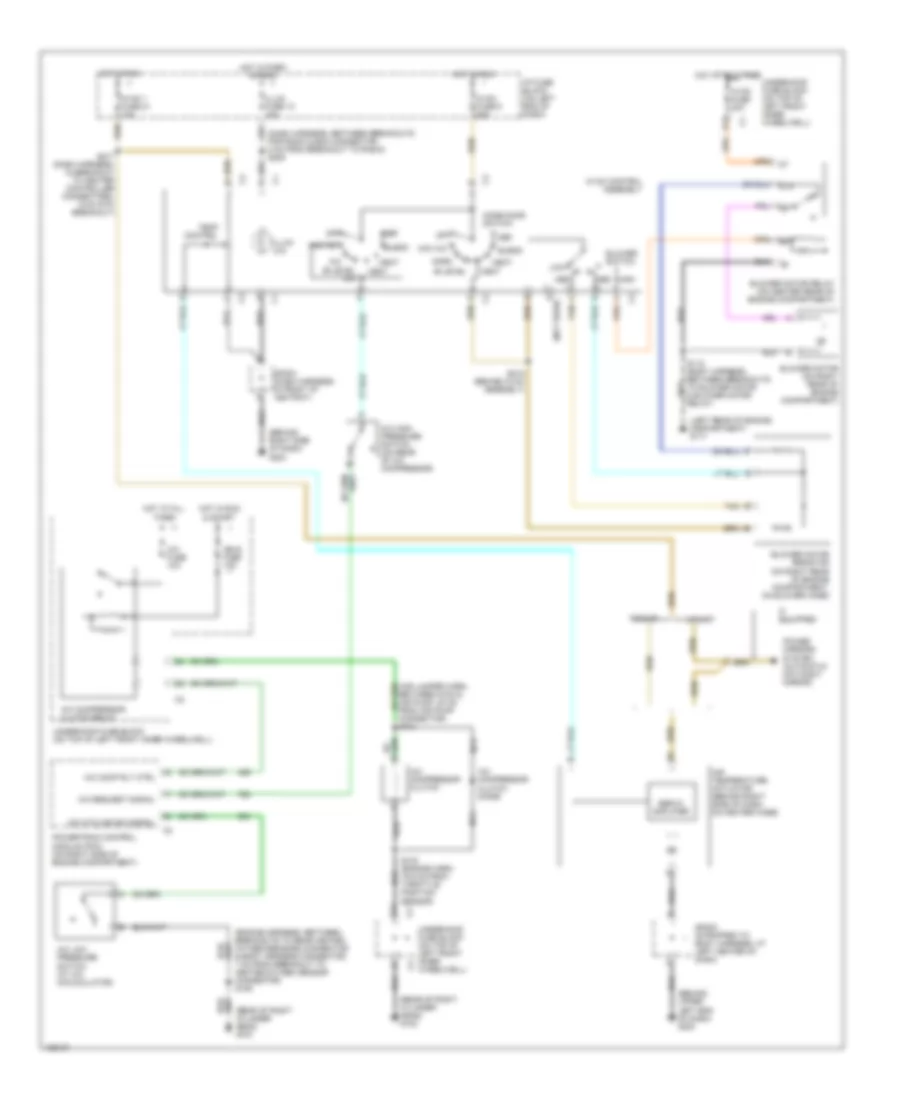
Manual A/C Wiring Diagram for GMC Sonoma 2004
 https://portal-diagnostov.com/license.html
Automotive Electricians Portal FZCO
Automotive Electricians Portal FZCO
https://portal-diagnostov.com/license.html
https://portal-diagnostov.com/license.html
Automotive Electricians Portal FZCO
Automotive Electricians Portal FZCOList of elements for Manual A/C Wiring Diagram for GMC Sonoma 2004:
- (behind right side of dash) g203
- (behind upper left end of dash) g200
- (dash harness, between breakouts for radio & bcm connector 8 cm from breakout to radio) s205
- (engine harness, between breakouts to rear heated oxygen sensors connector & body harness connector, 7 cm from breakout to heated oxygen sensor connector) s106
- (left rear of engine compartment) g117
- (rear of right cylinder head) g102
- (rear of right cylinder head) g103
- 87a
- A/c
- A/c comp rly ctrl
- A/c compressor clutch
- A/c compressor clutch diode
- A/c compressor clutch relay
- A/c cycling sw signal
- A/c fuse 10a
- A/c high pressure switch (on rear of a/c compressor)
- A/c low pressure switch (at a/c accumulator)
- A/c request signal
- Air temperature actuator (behind right side of dash, on heater case)
- Bi-level
- Bi-level a/c
- Blend
- Blower motor (on right rear of engine compartment)
- Blower motor relay (on center rear of engine compartment)
- Blower motor resistor (on right rear of engine compartment, on blower case)
- Blower switch
- Connector) s104
- D (not used)
- D12
- Def
- Heat
- High
- Hot at all times
- Hot in park & head
- Hot in run
- Hot in run & start
- Hvac 1 fuse 21 10a
- Hvac control assembly
- Hvac fuse 30a
- Hvac fuse 9 20a
- I/p fuse block (on left end of dash)
- If equipped
- Ign e fuse 10a
- Illum (x4)
- Illum fuse 12 10a
- Low
- Max a/c
- Med
- Mode door switch
- Nca
- Norm
- Off
- Pickup
- Power mirrors system (automatic day/night mirror)
- Powertrain control module (pcm) (on right side of engine compartment)
- S103 (engine harn, 19.5 cm from throttle position sensor)
- S118 (body harness, between breakouts to blower motor & blower motor relay)
- S215 (behind hvac assembly)
- S217 (dash harness, in breakout to heater controller connectors, 6 cm into breakout)
- Servo amplifier
- Sp202 (strapped to body harness, at left center of dash)
- Sp203 (dash harness, in front of ashtray)
- Tan
- Temp control
- Underhood fuse block (on top of left front inner wheelwell)
- Utility
- Vent
ANTI-LOCK BRAKES
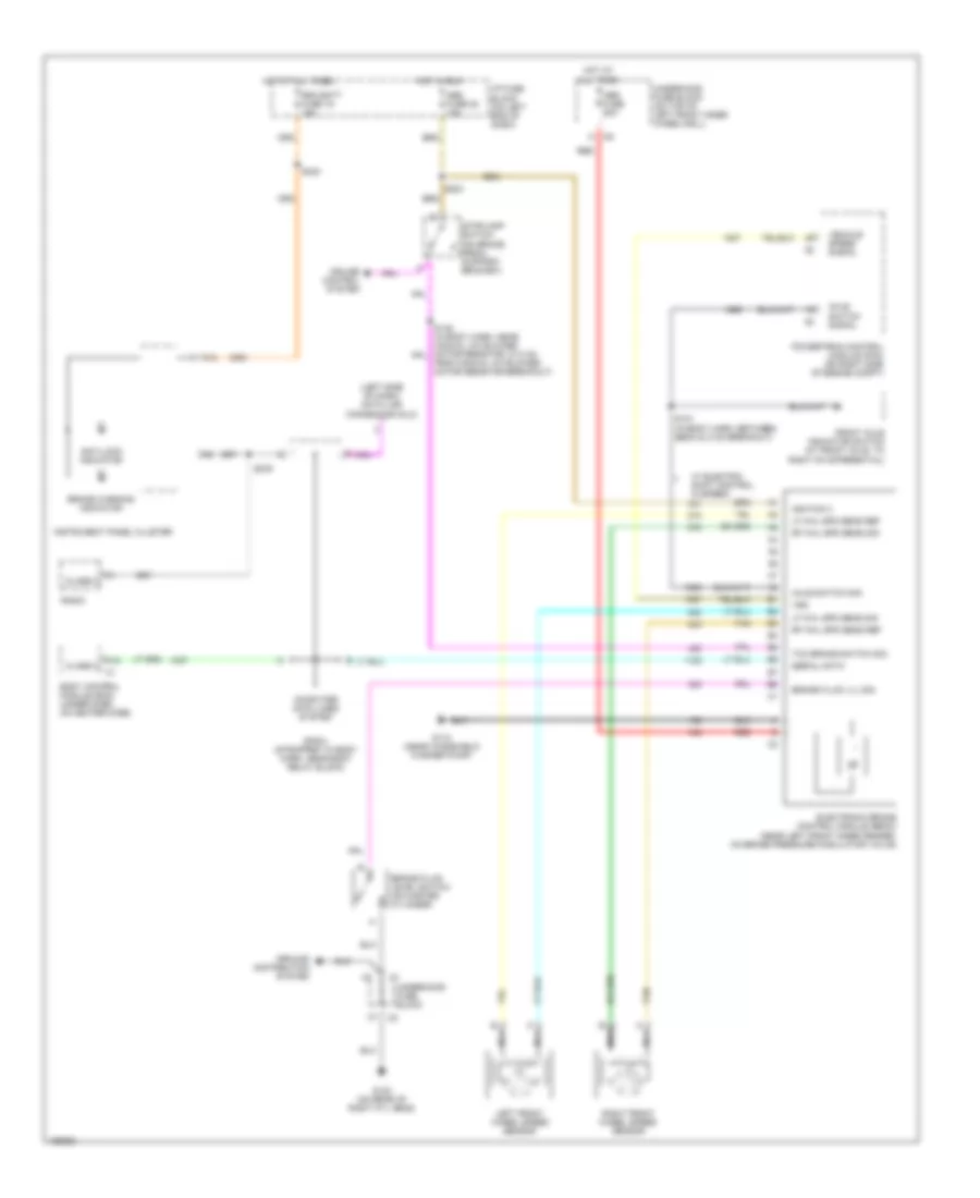
Anti-lock Brakes Wiring Diagram for GMC Sonoma 2004
 https://portal-diagnostov.com/license.html
Automotive Electricians Portal FZCO
Automotive Electricians Portal FZCO
https://portal-diagnostov.com/license.html
https://portal-diagnostov.com/license.html
Automotive Electricians Portal FZCO
Automotive Electricians Portal FZCOList of elements for Anti-lock Brakes Wiring Diagram for GMC Sonoma 2004:
- (left side of dash) data link connector (dlc)
- A10
- A12
- Abs fuse 22 10a
- Abs fuse 60a
- Anti-lock indicator
- Axle switch sig
- Axle switch signal
- Body control module (bcm) (under dash, on heater case)
- Brake fluid level switch (on master cylinder)
- Brake fluid lvl sig
- Brake warning indicator
- Class 2
- Computer data lines system
- Cruise control system
- Electronic brake control module (ebcm) (near left front inner fender, on brake pressure modulator valve)
- From manual a/c blower motor resistor breakout)
- Front axle indicator switch (at front axle, to right of differential)
- G102 (on rear of right cyl head)
- G110 (near windshield washer pump)
- Ground distribution system
- Hot at all times
- Hot in run
- I/p fuse block (on left end of dash)
- Ignition 3
- Instrument panel cluster
- Left front wheel speed sensor
- Lf whl spd sens ref
- Lf whl spd sens sig
- Nca
- Powertrain control module (pcm) (on right side of engine compt)
- Radio
- Rdo batt fuse 19 15a
- Red
- Rf whl spd sens ref
- Rf whl spd sens sig
- Right front wheel speed sensor
- S121 (in body harn, between ebcm & c102 breakout)
- S203
- S240
- S276
- Serial data
- Sp201 (strapped to body harn, near body relay block)
- Stoplamp switch (on brake pedal support bracket)
- Tan
- Tcc brake switch sig
- Underhood fuse block
- Underhood fuse block (on top of left front inner wheelwell)
- Vehicle speed signal
- Vss
- W/ electric shift control (2 speed)
ANTI-THEFT
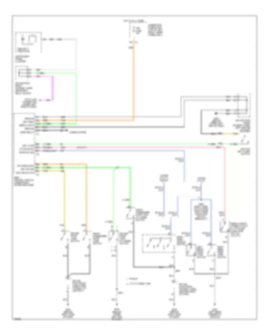
Forced Entry Wiring Diagram for GMC Sonoma 2004
 https://portal-diagnostov.com/license.html
Automotive Electricians Portal FZCO
Automotive Electricians Portal FZCO
https://portal-diagnostov.com/license.html
https://portal-diagnostov.com/license.html
Automotive Electricians Portal FZCO
Automotive Electricians Portal FZCOList of elements for Forced Entry Wiring Diagram for GMC Sonoma 2004:
- (utility)
- 2 door utility, pickup
- 4 door utility
- A12
- B10
- B11
- Battery
- Body control module (under dash, on heater case)
- C211
- Data link connector (under left side of dash)
- Door sw sig
- Driver door jamb switch
- Driver door lock cylinder switch
- Drv dr switch
- Fr handle sw
- Front passenger door jamb switch
- Front passenger door lock cylinder switch
- G200 (behind upper left end of dash)
- G202 (behind upper left end of dash)
- G203 (behind right side of dash)
- G205 (behind right side of dash)
- G450 (left rear corner of vehicle)
- Ground
- Horn relay
- Horns system
- Hot at all times
- Ignition key alarm switch
- Instrument panel cluster
- Key in ign
- Key sw sig
- Left rear door jamb switch
- Liftgate sw
- Pickup
- Rear window wiper cutout & liftglass ajar jamb switch (utility)
- Right door handle switch
- Right rear door jamb switch
- S305 (body harn, 22.5 cm from right rear door jamb switch breakout)
- S427
- S501
- S601
- Security indicator
- Serial data
- Splice pack sp201 (on body harn, near body relay block)
- Splice pack sp202 (on body harn, left center of dash)
- Splice pack sp203 (dash harn, in front of ashtray)
- Splice pack sp204 (on body harn, center front of dash)
- Tan
- Tbc fuse 10a
- Underhood fuse block (top of left front inner wheelwell)
- Utility/crew cab
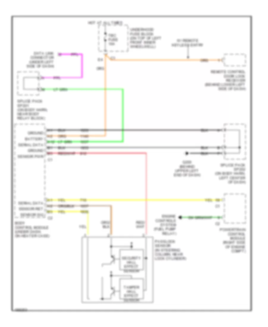
Pass-Key Wiring Diagram for GMC Sonoma 2004
 https://portal-diagnostov.com/license.html
Automotive Electricians Portal FZCO
Automotive Electricians Portal FZCO
https://portal-diagnostov.com/license.html
https://portal-diagnostov.com/license.html
Automotive Electricians Portal FZCO
Automotive Electricians Portal FZCOList of elements for Pass-Key Wiring Diagram for GMC Sonoma 2004:
- A12
- Battery
- Body control module (under dash, on heater case)
- Data link connector (under left side of dash)
- Engine controls system (fuel pump relay)
- G200 (behind upper left end of dash)
- Ground
- Hot at all times
- Passlock sensor (in steering column, near lock cylinder)
- Powertrain control module (right side of engine compt)
- Remote control door lock receiver (behind lower left side of dash)
- Security hall effect sensor
- Sensor pwr
- Sensor ret
- Sensor sig
- Serial data
- Splice pack sp201 (on body harn, near body relay block)
- Splice pack sp202 (on body harn, left center of dash)
- Tamper hall effect sensor
- Tbc fuse 10a
- Underhood fuse block (on top of left front inner wheelwell)
- W/ remote keyless entry
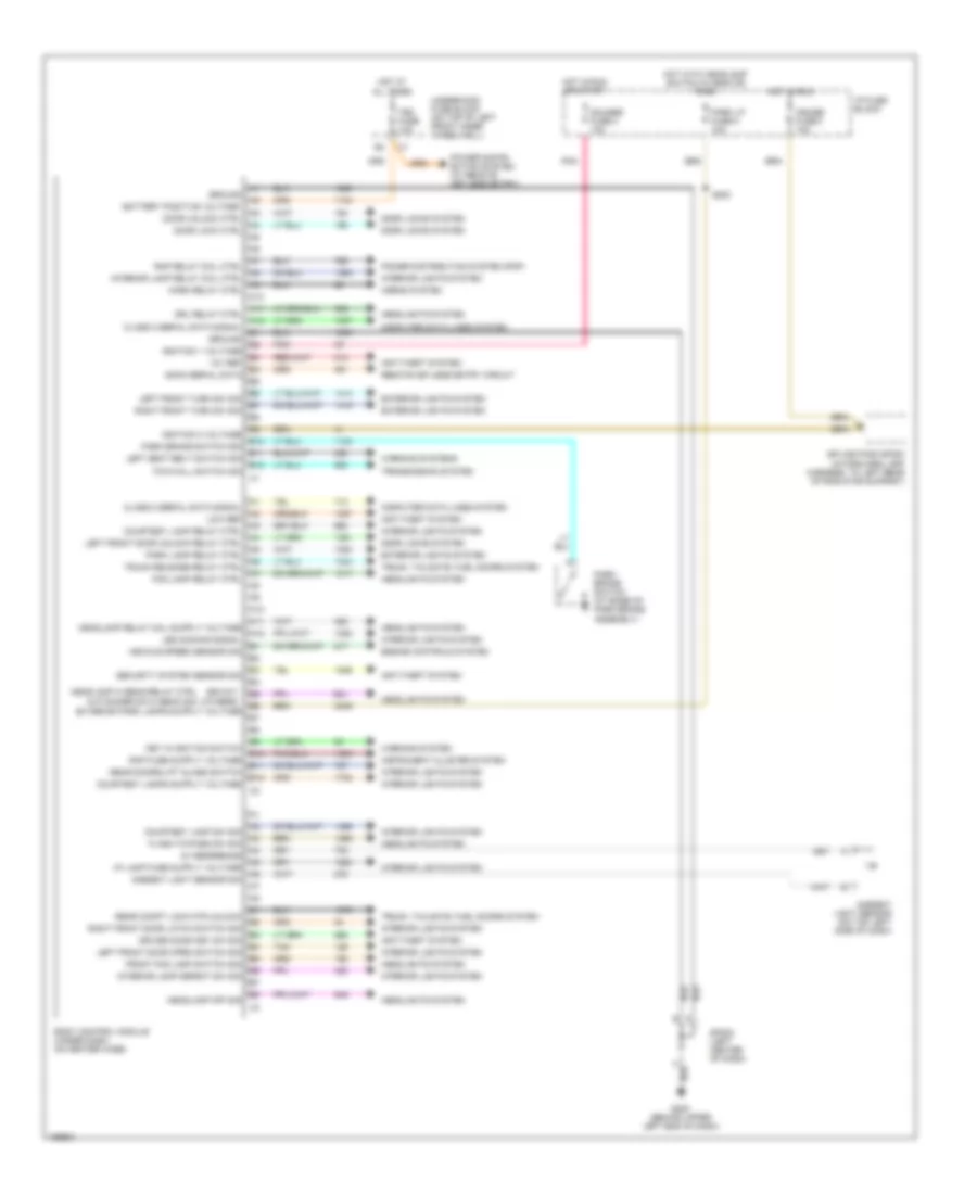
BODY CONTROL MODULES
Body Control Modules Wiring Diagram for GMC Sonoma 2004
 https://portal-diagnostov.com/license.html
Automotive Electricians Portal FZCO
Automotive Electricians Portal FZCO
https://portal-diagnostov.com/license.html
https://portal-diagnostov.com/license.html
Automotive Electricians Portal FZCO
Automotive Electricians Portal FZCOList of elements for Body Control Modules Wiring Diagram for GMC Sonoma 2004:
- (envoy)
- (others)
- 12v ref
- 5v reference
- A10
- A11
- A12
- Ambient light sensor (on top left side of dash)
- Ambient light sensor sig
- Anti-theft system
- B10
- B11
- B12
- Battery positive voltage
- Body control module (under dash, on heater case)
- Class 2 serial data signal
- Computer data lines system
- Courtesy lamp relay ctrl
- Courtesy lamp sw sig
- Cruise fuse 3 10a
- Door lock ctrl
- Door locks system
- Door unlock ctrl
- Driver door key sw sig
- Drl relay ctrl
- Engine controls system
- Exterior lights system
- Flash-to-pass sw sig
- Fog lamp relay ctrl
- Front fog lamp switch sig
- G200 (behind upper left end of dash)
- Gauges fuse 4 10a
- Gmcm serial data
- Ground
- Headlamp hi beam relay ctrl
- Headlamp off sig
- Headlights system
- Hlp dimmer sw hi beam sig
- Horn relay ctrl
- Horns system
- Hot at all times
- Hot in run
- Hot in run or start
- Hot with headlamp switch in head or park
- I/p fuse block
- Ignition 1 voltage
- Ignition 3 voltage
- Instrument cluster system
- Interior lamp defeat sw sig
- Interior lamp relay coil ctrl
- Interior lights system
- Key in ignition switch
- Led dimming signal
- Left front door open switch sig
- Left front door unlock relay ctrl
- Left front turn sw sig
- Left seat belt switch sig
- Low ref
- Park brake switch (at base of park brake assembly)
- Park brake switch sig
- Park lamp relay ctrl
- Park lp fuse 5 10a
- Pnk
- Power distri- bution system (w/ remote keyless entry)
- Power distribution system (rap)
- Rap relay coil ctrl
- Rear compt lock mtr unlock
- Rear doors/lift glass switch
- Remote keyless entry circuit
- Right front door latch switch sig
- Right front turn sw sig
- S283
- Security system sensor sig
- Sp202 (left center of dash)
- Splice pack sp200 (in forward lamp harness, to left rear of radiator support)
- Tan
- Tbc fuse 10a
- Tow/hall switch sig
- Transmission system
- Trunk release relay ctrl
- Trunk, tailgate, fuel doors system
- Underhood fuse block (on top of left front inner wheelwell)
- Vehicle speed sensor sig
- Warning system
- Warning systems
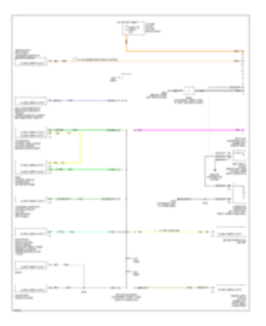
COMPUTER DATA LINES
Computer Data Lines Wiring Diagram for GMC Sonoma 2004
 https://portal-diagnostov.com/license.html
Automotive Electricians Portal FZCO
Automotive Electricians Portal FZCO
https://portal-diagnostov.com/license.html
https://portal-diagnostov.com/license.html
Automotive Electricians Portal FZCO
Automotive Electricians Portal FZCOList of elements for Computer Data Lines Wiring Diagram for GMC Sonoma 2004:
- (behind right kick panel) transfer case shift control module
- (not used)
- A12
- Body control module (under dash, on heater case)
- Body relay block (behind left side of dash, near dash fuse block)
- Cigar ltr fuse 2 15a
- Class 2 serial data
- Data link connector (dlc) (under left side of dash)
- Driver information center
- Electronic brake control module (ebcm) (near left front inner fender, on brake pressure modulator valve)
- G105 (on rear of left cylinder head)
- G200 (behind upper left end of dash)
- Ground distribution system
- Hot at all times
- I/p fuse block (on left end of dash)
- Inflatable restraint sensing & diagnostic module (under console & carpet, between front seats)
- Instrument panel cluster
- Memory seat module (under left front seat) (if equipped)
- Powertrain control module (pcm) (on right side of engine compartment)
- Radio
- S152
- S276
- Sp202 (strapped to body harn, at left center of dash)
- Splice pack sp201 (strapped to body harn, near i/p fuse block)
- Transfer case shift control module (w/ 4wd) (behind right kick panel)
- Underhood fuse block (on top of left front inner wheelwell)
- W/ trip computer
- W/ two speed electronic control
CRUISE CONTROL
Cruise Control Wiring Diagram for GMC Sonoma 2004
 https://portal-diagnostov.com/license.html
Automotive Electricians Portal FZCO
Automotive Electricians Portal FZCO
https://portal-diagnostov.com/license.html
https://portal-diagnostov.com/license.html
Automotive Electricians Portal FZCO
Automotive Electricians Portal FZCOList of elements for Cruise Control Wiring Diagram for GMC Sonoma 2004:
- (on left side of firewall)
- 2-speed push button control
- 2.2l
- 4.3l
- 4wd only
- A/t
- A12
- A13
- A14
- A15
- Abs fuse 22 10a
- Antilock brake system
- B (2.2l) (4.3l)
- Bare
- Body computer system
- Body relay block (behind left side of dash)
- Brake cutout 1
- Brake/clutch signal
- C116 (near top right rear of transmission)
- Clutch pedal position & cruise control
- Cruise control module
- Cruise fuse 3 10a
- Cruise on/off input
- Cruise status
- Cut-out switch (clutch pedal support bracket)
- D (2.2l) (4.3l)
- Exterior lights system
- G104 (left rear of cylinder head)
- G105 (4.3l) (left rear of cylinder head) (2.2l) (right rear of engine)
- G117 (left rear of engine compt)
- Ground
- Hot in run
- I/p fuse block (left end of dash)
- Ignition
- Instrument cluster system
- M/t
- Multifunction switch
- Off
- Powertrain control module (right front of engine compt)
- R/a
- Resume/accel input
- S134
- S138 (body harn, left rear of engine compt)
- S140
- S152
- S203 (4.3l)
- Set sw
- Set/coast input
- Sp200 (body harn, center front of dash)
- Stoplamp switch (brake pedal support bracket)
- Underhood fuse block (on top of left front inner wheelwell)
- Vehicle speed input
- Vehicle speed sensor (vss) (on rear of transmission)
- Vss
- Vss high
- Vss low
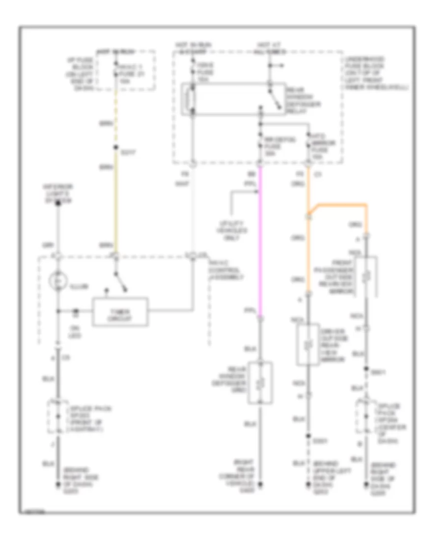
DEFOGGERS
Defoggers Wiring Diagram for GMC Sonoma 2004
 https://portal-diagnostov.com/license.html
Automotive Electricians Portal FZCO
Automotive Electricians Portal FZCO
https://portal-diagnostov.com/license.html
https://portal-diagnostov.com/license.html
Automotive Electricians Portal FZCO
Automotive Electricians Portal FZCOList of elements for Defoggers Wiring Diagram for GMC Sonoma 2004:
- (behind right side of dash) g203
- (behind right side of dash) g205
- (behind upper left end of dash) g202
- (right rear corner of vehicle) g420
- Driver outside rear- view mirror
- Front passenger outside rearview mirror
- Hot at all times
- Hot in run
- Hot in run & start
- Htd mirror fuse 10a
- Hvac 1 fuse 21 10a
- Hvac control assembly
- I/p fuse block (on left end of dash)
- Ign e fuse 10a
- Illum
- Interior lights system
- Nca
- On led
- Rear window defogger grid
- Rear window defogger relay
- Rr defog fuse 30a
- S217
- S501
- S601
- Splice pack sp203 (front of ashtray)
- Splice pack sp204 (center of dash)
- Timer circuit
- Underhood fuse block (on top of left front inner wheelwell)
- Utility vehicles only
ENGINE PERFORMANCE
4.3L VIN X
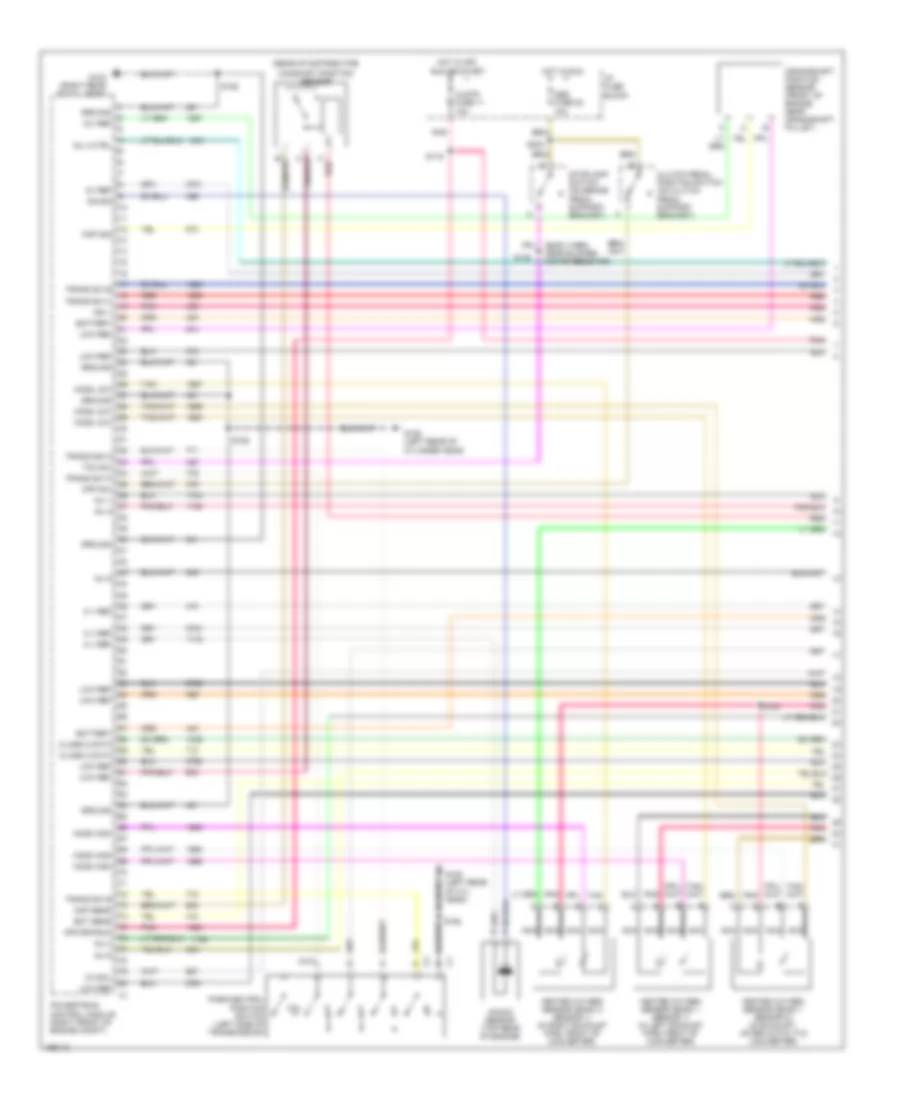
4.3L VIN X, Engine Performance Wiring Diagram (1 of 4) for GMC Sonoma 2004
 https://portal-diagnostov.com/license.html
Automotive Electricians Portal FZCO
Automotive Electricians Portal FZCO
https://portal-diagnostov.com/license.html
https://portal-diagnostov.com/license.html
Automotive Electricians Portal FZCO
Automotive Electricians Portal FZCOList of elements for 4.3L VIN X, Engine Performance Wiring Diagram (1 of 4) for GMC Sonoma 2004:
- (body harn, near blower motor resistor)
- (rear of distributor)
- 12v ref
- 3-2 sol
- 5 v ref
- 5v ref
- Abs fuse 22 10a
- Battery
- C red
- Camshaft position sensor
- Ckp sig
- Class 2 data
- Clstr fuse 11 10a
- Clutch pedal position switch (on clutch pedal support bracket)
- Cmp sens
- Cpp sw
- Crankshaft position sensor (front of engine near crankshaft pulley)
- Ect sens
- G103 (right rear of cyl head)
- G105 (left rear of cyl head)
- G105 (left rear of cylinder head)
- Ground
- Heated oxygen sensor (bank 1 sensor 1) (in left exhaust pipe, front of converter)
- Heated oxygen sensor (bank 1 sensor 2) (in exhaust, after catalytic converter)
- Heated oxygen sensor (bank 2 sensor 1) (in right exhaust pipe, front of converter)
- Ho2s high
- Ho2s low
- Hot in off, run or start
- Hot in run
- I/p fuse block
- Ign 1
- Inj 1
- Inj 2
- Inj 3
- Inj 4 ctrl
- Inj 5
- Inj 6
- Knock sensor (top rear of engine)
- Ks sig
- Low ref
- Nca
- Off/crk/run
- P/n
- Park/neutral position switch (left side of transmission)
- Pnk
- Powertrain control module (right front of engine compt)
- Red
- S100
- S106
- S116
- S138
- S152
- S203
- Stoplamp switch (on brake pedal support bracket)
- Tan
- Tcc sw
- Trans sig a
- Trans sw b
- Trans sw c
- Trans sw p
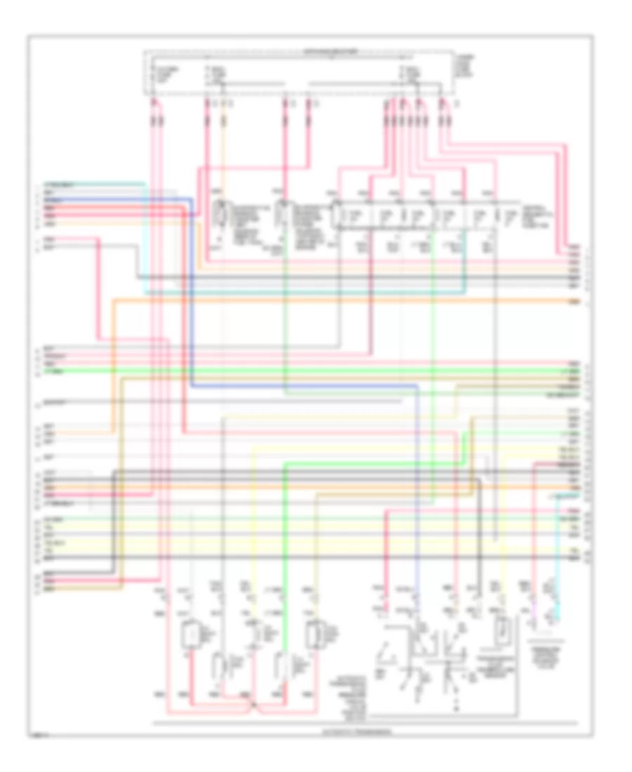
4.3L VIN X, Engine Performance Wiring Diagram (2 of 4) for GMC Sonoma 2004
 https://portal-diagnostov.com/license.html
Automotive Electricians Portal FZCO
Automotive Electricians Portal FZCO
https://portal-diagnostov.com/license.html
https://portal-diagnostov.com/license.html
Automotive Electricians Portal FZCO
Automotive Electricians Portal FZCOList of elements for 4.3L VIN X, Engine Performance Wiring Diagram (2 of 4) for GMC Sonoma 2004:
- 1-2 shift sol
- 2-3 shift sol
- 3-2 shift sol
- A10
- Automatic transmission
- Automatic transmission fluid pressure manual valve position switch
- B10
- C10
- Central sequential fuel injection
- D10
- D2 sw
- D3 sw
- D4 sw
- E10
- Ecm i fuse 15a
- Eng i fuse 10a
- Evaporative emission canister purge solenoid (top right center of engine)
- Evaporative emission canister vent solenoid (rear of fuel tank)
- Fuel inj
- Hot in run or start
- Lo sw
- Oxygen fuse 20a
- Pnk
- Pressure control solenoid valve
- Red
- Rev sw
- Tan
- Tcc pwm sol
- Tcc sol
- Transmission fluid temperature sensor
- Under- hood fuse block
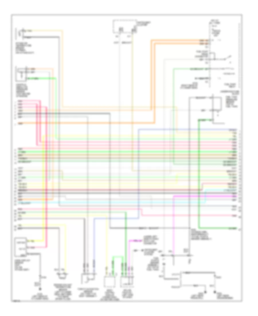
4.3L VIN X, Engine Performance Wiring Diagram (3 of 4) for GMC Sonoma 2004
 https://portal-diagnostov.com/license.html
Automotive Electricians Portal FZCO
Automotive Electricians Portal FZCO
https://portal-diagnostov.com/license.html
https://portal-diagnostov.com/license.html
Automotive Electricians Portal FZCO
Automotive Electricians Portal FZCOList of elements for 4.3L VIN X, Engine Performance Wiring Diagram (3 of 4) for GMC Sonoma 2004:
- (under left side of dash) data link connector
- 12v in
- A11
- A12
- Body control module (under dash, on heater case)
- Ecm b fuse 20a
- Eng spd
- Engine coolant temperature sensor (left cylinder head, between two rear spark plugs)
- Fuel pump & sender assembly (on top of fuel tank)
- Fuel pump prime connector
- Fuel pump relay
- Fuel tank pressure sensor (top of fuel tank)
- G102 (right rear of cylinder head)
- G105 (left rear of cylinder head)
- G402 (left rear crossmember)
- G402 (left rear frame rail)
- Gnd
- Hot at all times
- Instrument cluster
- Instrument cluster system
- Intake air temperature sensor (in fresh air intake duct)
- Maf sig
- Manifold absolute pressure sensor (top center of engine)
- Mass airflow sensor (maf) (on air intake assy)
- Mil input
- Pick-up
- Pnk
- Red
- S152
- S422 (chassis harn, near breakout to fuel pump & sender assembly)
- S423
- Splice pack 201 (left side of dash)
- Tan
- Tan b
- Throttle position sensor (on throttle body assembly)
- Underhood fuse block
- Utility
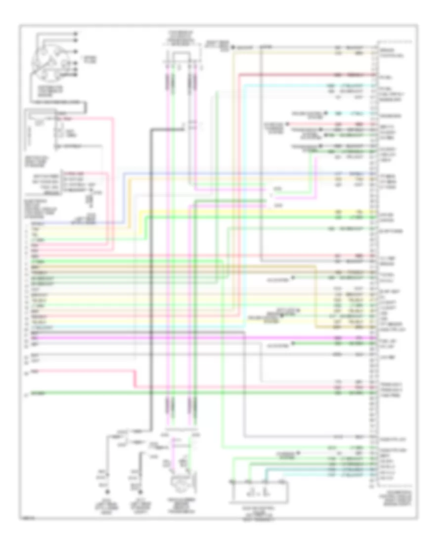
4.3L VIN X, Engine Performance Wiring Diagram (4 of 4) for GMC Sonoma 2004
 https://portal-diagnostov.com/license.html
Automotive Electricians Portal FZCO
Automotive Electricians Portal FZCO
https://portal-diagnostov.com/license.html
https://portal-diagnostov.com/license.html
Automotive Electricians Portal FZCO
Automotive Electricians Portal FZCOList of elements for 4.3L VIN X, Engine Performance Wiring Diagram (4 of 4) for GMC Sonoma 2004:
- (not used)
- (right rear of cyl head) g103
- (top rear of automatic transmission) c116 (m-m)
- 1-2 shift
- 12 v ref
- 2-3 shift
- 2wd
- 4wd
- A/c clu
- A/c low
- A/c req
- A/c system
- Anti-lock brake system
- Axle sw
- Charging system
- Cruise control system
- Cruise eng
- Distributor (top rear of engine)
- Electronic ignition control module (top right side of engine)
- Engine spd
- Evap purge
- Evap vent
- Fuel lev
- Fuel pmp rly
- G104 (left rear of cylinder head)
- G105 (left rear of cyl head)
- G117 (left rear of engine compt)
- Gen f
- Gen t/o
- Ground
- H02s htr low
- High voltage coil wire
- Ho2s htr high
- Ho2s htr low
- Iac a hi
- Iac a lo
- Iac b hi
- Iac b lo
- Iat sens
- Ic timing
- Idle air control valve (on throttle body assembly)
- Ign timing sig.
- Ignition coil (right side of engine)
- Ignition feed
- Low ref
- Maf sig
- Map sig
- Mil
- Nca
- Pc sol
- Pnk
- Pnk a
- Powertrain control module (right side of engine compt)
- Red
- S106
- S134
- S140
- S152
- Spark plugs
- Starting/ charging system
- Tach. sig.
- Tan
- Tank pres
- Tcc pwm sol
- Tcc sol
- Tft sensor
- Tp sens
- Trans sig a
- Trans sig c
- Transmission system
- Vehicle speed sensor (rear of transmission)
- Vss
- Vss hi
- Vss low
EXTERIOR LIGHTS
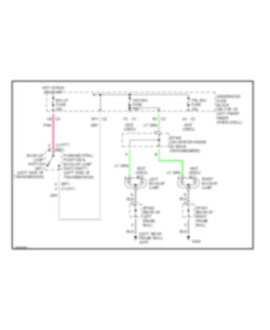
Back-up Lamps Wiring Diagram for GMC Sonoma 2004
 https://portal-diagnostov.com/license.html
Automotive Electricians Portal FZCO
Automotive Electricians Portal FZCO
https://portal-diagnostov.com/license.html
https://portal-diagnostov.com/license.html
Automotive Electricians Portal FZCO
Automotive Electricians Portal FZCOList of elements for Back-up Lamps Wiring Diagram for GMC Sonoma 2004:
- (a/t)
- (left rear frame rail) g475
- (m/t) a
- (not used)
- B/u lp fuse 25a
- B11 c2
- Back-up lamp switch (m/t) (left side of transmission)
- C b
- C1 (m/t)
- C1 f
- C3 a4
- C3 b3
- C8 c2
- F3 c1
- G422
- Hot in run or start
- Left backup lamp
- Park/neutral position & back-up lamp switch (left side of transmission)
- Pnk
- Right backup lamp
- Sp400 (on center inside of rear crossmember)
- Sp401 (rear of right frame rail)
- Sp402 (rear of left frame rail)
- Trl b/u fuse 10a
- Underhood fuse block (on top of left front inner wheelwell)
- Veh b/u fuse 15a
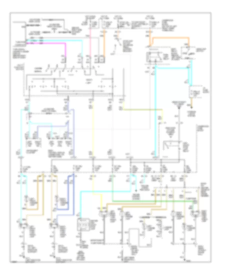
Exterior Lamps Wiring Diagram for GMC Sonoma 2004
 https://portal-diagnostov.com/license.html
Automotive Electricians Portal FZCO
Automotive Electricians Portal FZCO
https://portal-diagnostov.com/license.html
https://portal-diagnostov.com/license.html
Automotive Electricians Portal FZCO
Automotive Electricians Portal FZCOList of elements for Exterior Lamps Wiring Diagram for GMC Sonoma 2004:
- (behind right side of dash) g205
- (fleetside) d
- (in center front of dash) sp204
- (left rear frame rail) g475
- (not used)
- (rear of right cyl head) g102
- A10
- A8 c1
- B12 c1
- B2 gnd
- Body control module (under dash, on heater case)
- Body relay block (behind left side of dash)
- C1 a4
- C1 c1
- C1 d11
- C1 e2
- C10 c1
- C2 c1
- C3 c1
- C3 e4
- C5 c3
- Center high mount stop lamp
- Cruise control system
- D2 c3
- D6 c3
- E (sportside)
- E9 c1
- F10 c1
- F11
- F12 c1
- Fleetside
- Fr prk fuse 10a
- From stop lp fuse (diagram 1 of 1)
- G111 (left radiator support)
- G112 (right radiator support)
- G202 (behind upper left end of dash)
- G422
- Haz lp fuse 20a
- Hazard
- Head
- Headlamp switch
- High mount stop lamp relay
- Hot at all times
- Hot in run or start
- I/p fuse block
- Instrument cluster
- Interior lights system
- Left
- Left front marker lamp
- Left front park/ turn signal lamp
- Left license lamp
- Left rear marker lamp
- Left rear park/ turn signal lamp
- Left turn in
- Left turn ind
- License lamp
- Lr prk fuse 10a
- Lt trn fuse 10a
- Lt turn fuse 10a
- Multi- function switch
- Nca
- Normal
- Off
- Park
- Park lamp relay
- Park lp fuse 20a
- Park rly ctrl
- Pnk
- Prk lp fuse 5 10a
- Right
- Right front marker lamp
- Right front park/ turn signal lamp
- Right license lamp
- Right rear marker lamp
- Right rear park/ turn signal lamp
- Right turn in
- Right turn ind
- Rr prk fuse 10a
- Rt trn fuse 10a
- Sp100 (at left radiator support)
- Sp101 (at right radiator support)
- Sp400 (on center inside of rear cross- member)
- Sp401 (rear of right frame rail)
- Sp402 (rear of left frame rail)
- Sportside
- Stop lp fuse 20a
- Stoplamp switch (on brake pedal support bracket)
- To high mount stop lamp relay (diagram 1 of 1)
- Tr chmsl fuse 10a
- Trailer wiring provision
- Turn fuse 20a
- Turn pwr c1 flshr out
- Turn signal/ hazard flasher module (behind right side of dash)
- Underhood fuse block
- Underhood fuse block (on top of left front inner wheelwell)
- Veh chmsl fuse 10a
- W/ power door locks
- W/o power door locks
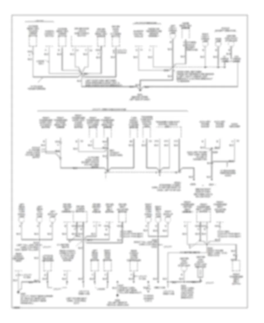
GROUND DISTRIBUTION
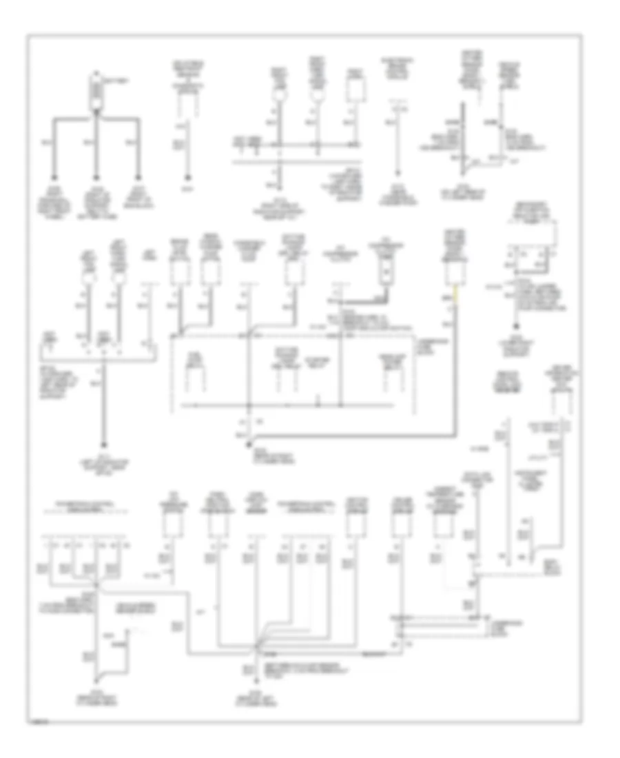
Ground Distribution Wiring Diagram (1 of 3) for GMC Sonoma 2004
 https://portal-diagnostov.com/license.html
Automotive Electricians Portal FZCO
Automotive Electricians Portal FZCO
https://portal-diagnostov.com/license.html
https://portal-diagnostov.com/license.html
Automotive Electricians Portal FZCO
Automotive Electricians Portal FZCOList of elements for Ground Distribution Wiring Diagram (1 of 3) for GMC Sonoma 2004:
- (between icm & map sensor breakout, 8 cm from breakout tp icm)
- (not used)
- (not used) f
- (w/o trip) (w/ trip)
- A c2
- A/c compressor clutch
- A/c compressor clutch diode
- A/c low pressure switch
- A/t
- A18
- Ambient temperature sensor (w/ overhead console)
- Bare
- Battery
- Body relay block
- Brake fluid level switch
- Breakout to a/c comp and cutoff switch)
- Cruise control module
- Cylinder head)
- D12
- Data link connector (dlc)
- Daytime running lamps (drl) relay
- Daytime running lamps (drl) relay (zr2)
- Driver information center (dic) (utility)
- Electronic brake control module
- Fuel pump relay
- G100 (lower right radiator support)
- G101
- G102 (rear of right cylinder head)
- G103 (rear of right
- G104 (on left rear of cylinder head)
- G105 (rear of left cylinder head)
- G106 (right frame rail, forward of right front wheel)
- G107 (right front of eng block)
- G108 (right of radiator support, next to battery fuse)
- G110 (near windshield washer pump)
- G111 (left of radiator support, near sp100)
- G112 (right side of radiator support, near sp 101)
- Headlamp power relay
- Heated oxygen sensor (ho2s) (bank 1 sensor 1) shield
- Heated oxygen sensor (ho2s) (bank 1 sensor 2)
- Ignition control module
- Inflatable restraint sensing & diagnostic module
- Instrument panel cluster (ipc)
- Left front fog lamp
- Left front park/ turn signal lamp
- Left horn
- M/t
- Mass airflow (maf) sensor
- Nca
- Park/ neutral position (pnp) switch
- Powertrain control module (pcm)
- Rear window washer pump motor
- Remote control door lock receiver
- Right front fog lamp
- Right front park/ turn signal lamp
- Right horn
- S106 (eng harn, 7 cm from breakout to ho2s connector)
- S140 (eng harn, 13 cm from vss breakout)
- S140 (eng harn, 7 cm from vss breakout)
- S152
- Secondary air injection reactor (air) pump
- Sp100 (in forward lamp harn, to left rear of radiator support)
- Sp101 (in forward lamp harn, to right inside of radiator support)
- Starter relay
- Underhood fuse block
- Utility
- Vehicle speed sensor (vss) shield
- Vehicle speed sensor shield
- W/ a/c
- W/ k18
- W/ rke
- Windshield washer fluid pump
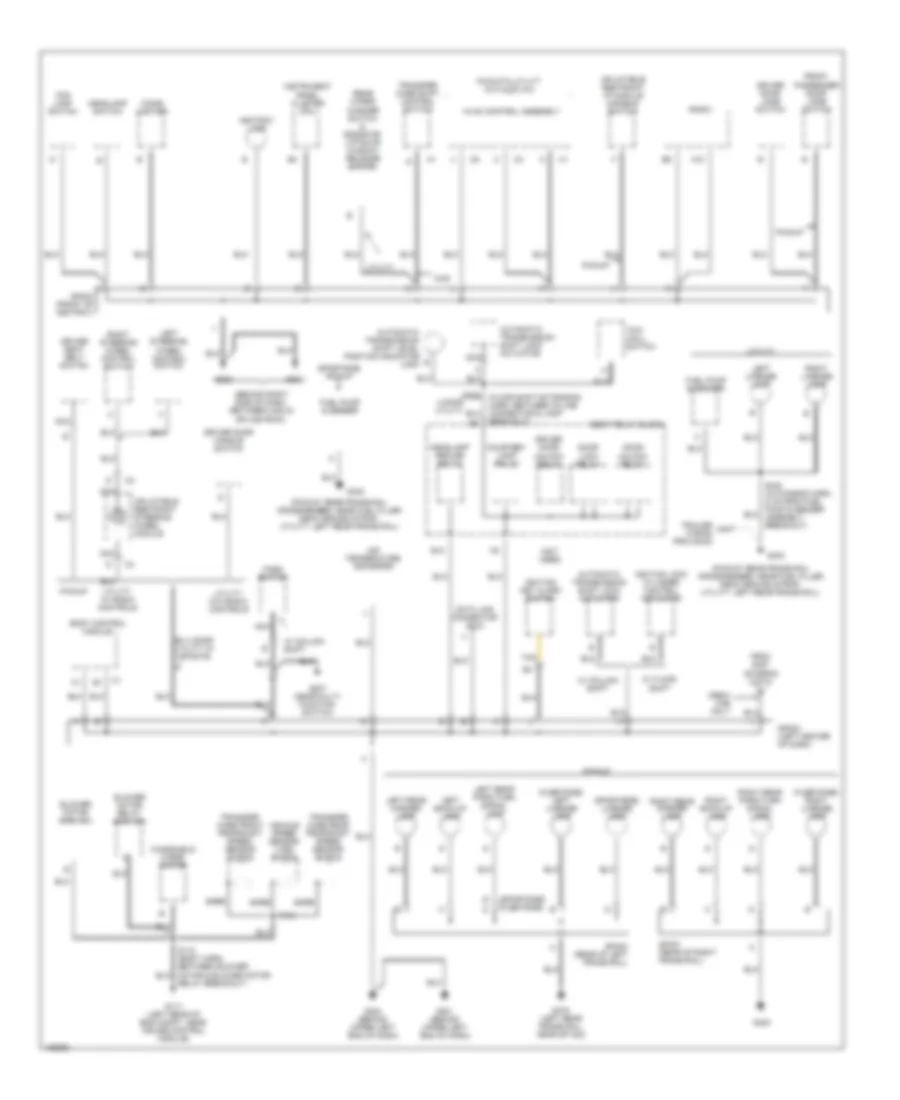
Ground Distribution Wiring Diagram (2 of 3) for GMC Sonoma 2004
 https://portal-diagnostov.com/license.html
Automotive Electricians Portal FZCO
Automotive Electricians Portal FZCO
https://portal-diagnostov.com/license.html
https://portal-diagnostov.com/license.html
Automotive Electricians Portal FZCO
Automotive Electricians Portal FZCOList of elements for Ground Distribution Wiring Diagram (2 of 3) for GMC Sonoma 2004:
- (behind right side of dash, between c203 &
- (fleetside)
- (fleetside) right license lamp
- (not used)
- (pickup: rear frame rail crossmember, near fuel filler neck ground strap, utility: left rear frame rail)
- (sportside) (fleetside)
- (sportside) license lamp
- 4wd
- A12
- Air temperature actuator
- Ashtray lamp
- Automatic transmission shift level position indicator lamp
- Automatic transmission shift lock actuator
- B12
- Bare
- Blower motor (man a/c)
- Blower motor relay (man a/c)
- Body control module
- Body relay block
- Breakout)
- Cigar lighter
- Courtesy lamp relay
- Crew cab only
- Data link connector (dlc)
- Door lock relay
- Door unlock relay
- Driver door handle switch
- Driver door jamb switch
- Driver door unlock relay
- Driver seat belt switch
- Ex 4 door utility w/ liftgate
- Fog lamp switch
- From s427 (diagram 3 of 3)
- Front passenger door jamb switch
- Fuel pump & sender
- G117 (left rear of eng compt, near cruise control module)
- G200 (behind upper left end of dash)
- G201 (behind upper left end of dash)
- G203
- G204
- G207 (near multi- function switch)
- G402
- G422
- G475 (left rear frame rail, near sp 402)
- Headlamp ground relay
- Headlamp switch
- Hvac control assembly
- Ignition key alarm switch
- Ignition lock cylinder control actuator
- Inflatable restraint i/p module disable switch
- Inflatable restraint steering wheel module
- Instrument panel cluster (ipc)
- Left back-up lamp
- Left license lamp
- Left rear marker lamp
- Left rear park/turn signal lamp
- Left steering wheel control switch
- Nca
- Park switch
- Pickup
- Pickup & utility w/o auto a/c
- Radio
- Rear wiper/ washer switch & endgate/ liftgate window release switch
- Relay breakout)
- Right back-up lamp
- Right license lamp
- Right rear marker lamp
- Right rear park/turn signal lamp
- Right steering wheel control switch
- S134
- S335 4 door utility
- S423 (in chassis harn, 8 cm from fuel pump & sender assembly breakout)
- Sp202 (left center of dash)
- Sp203 (front of ashtray)
- Sp401 (rear of right frame rail)
- Sp402 (rear of left frame rail)
- Splice pack)
- Sportside pickup
- Tan
- Tow haul switch
- Trailer wiring provision
- Transfer case front propshaft speed sensor shield
- Transfer case rear propshaft speed sensor shield
- Transfer case shift control switch
- Utility
- Utility w/ radio controls
- Utility w/o radio controls
- Vehicle speed sensor (vss) shield
- W/ column shift
- W/ floor shift
- Windshield wiper motor
Ground Distribution Wiring Diagram (3 of 3) for GMC Sonoma 2004
 https://portal-diagnostov.com/license.html
Automotive Electricians Portal FZCO
Automotive Electricians Portal FZCO
https://portal-diagnostov.com/license.html
https://portal-diagnostov.com/license.html
Automotive Electricians Portal FZCO
Automotive Electricians Portal FZCOList of elements for Ground Distribution Wiring Diagram (3 of 3) for GMC Sonoma 2004:
- (8-way pwr seat)
- (auxiliary power tray harn, near in-line i/p connector)
- (behind right side of dash between c203 & splice pack)
- (dome harn, between inside air temperature sensor & left vanity mirror lamp breakout, 5 cm from breakout to sensor)
- (left door harn, between door speaker & door lock & side window switch breakout)
- (left power seat harn, 15 cm from c317)
- (others)
- (pickup b
- (utility) (pickup)
- (w/ mem) h d (6-way pwr seat)
- 4 door
- 4 door only
- Audio amplifier
- Auxiliary power outlet
- B a
- C10
- Center high mount stop lamp
- Center high mount stop lamp resistor
- Crew cab
- D12
- D13
- Dome lamp
- Driver door lock & side window switch
- Driver door lock cylinder switch
- Driver heated seat assembly
- Driver lumbar switch
- Driver memory seat module
- Driver outside rear view mirror
- Driver seat adjuster switch
- Driver seat belt switch
- Except crewcab)
- Front passenger door lock & side window switch
- Front passenger door lock & window switch
- Front passenger door lock cylinder switch
- Front passenger heated seat assembly
- Front passenger outside rear view mirror
- Front passenger seat adjuster switch
- Front passenger seat belt switch
- Front passenger seat lumbar switch
- G202 (behind upper left end of dash)
- G204
- G205
- G420 (utility: right rear corner of vehicle, near c402, pickup: on right rear frame rail)
- G450 (on left rear of vehicle, near c403)
- Inside air temperature sensor assembly
- Inside rear view mirror
- Left back-up lamp
- Left rear door jamb switch
- Left rear park/ turn signal lamp
- Left rear tail/ stop lamp
- Left vanity mirror lamp
- Liftgate release actuator
- Nca
- Outside rear view folding mirror switch
- Outside rear view mirror switch
- Pickup except crewcab
- Pickup w/ power door locks w/o keyless entry
- Rear window defogger grid
- Rear window wiper cutout & liftglass ajar jamb switch
- Rear window wiper motor controller
- Right back-up lamp
- Right rear door jamb switch
- Right rear park/ turn signal lamp
- Right rear tail/ stop lamp
- Right vanity mirror lamp
- S269
- S302
- S313
- S320 (right power seat harn, 15 cm from c315)
- S404 (body harn, 10 cm from high mount stop lamp breakout)
- S419 (left tail lamp jpr harn, 8 cm from c403, near taillamp)
- S420 (right tail lamp jpr harn, 8 cm from c402)
- S427 (lr body harn, near left rear taillamp breakout)
- S501
- S601 (in right door harn)
- Sp204 strapped to body harn, in center front of dash, left of sp 200)
- Sunroof control module
- To sp202 (diagram 2 of 3)
- Transfer case shift control module (np1)
- Transfer case shift control module (np8)
- Turn signal/ hazard flasher module
- Utility
- Utility & crew cab
- Utility & crewcab
- Utility w/ c25
- Utility w/ zm8
- Utility, crew cab & maxi-cab
- W/ enhanced performance audio
- W/ folding power mirrors
- W/ heated seats
- W/ mirror lamps
- W/ power door locks except pickup w/o keyless entry
- W/o mirror lamps
- Window lockout switch
HEADLIGHTS
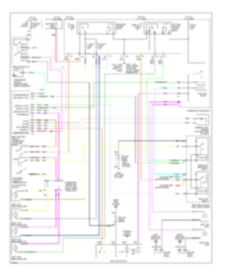
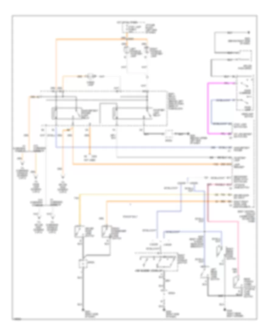
Headlights Wiring Diagram, with ZR2 for GMC Sonoma 2004
 https://portal-diagnostov.com/license.html
Automotive Electricians Portal FZCO
Automotive Electricians Portal FZCO
https://portal-diagnostov.com/license.html
https://portal-diagnostov.com/license.html
Automotive Electricians Portal FZCO
Automotive Electricians Portal FZCOList of elements for Headlights Wiring Diagram, with ZR2 for GMC Sonoma 2004:
- (2.2l)
- (4.3l)
- (left radiator support) g111
- (right radiator support) g112
- (right side of dash) g203
- 5v ref
- A11
- Ambient light sensor (top left side of dash)
- Auto
- B10
- B12
- Battery fuse 175a
- Body control module (under dash, on heater case)
- Body relay block (left side of dash)
- C1 d9
- Daytime running lamps relay (taped to body harness, near breakout for rear washer hose)
- Drl relay ctrl
- E10
- E11
- E12
- E13
- Exterior lights system
- Fog lamp relay
- Fog lamp switch
- Fog lp fuse 15a
- Fog lp ind
- Fog rly ctrl
- Fog sw in
- Ftp
- Ftp in
- G102 (rear of right cyl head)
- G102 (right front of engine block, under generator)
- Hdlp sw fuse 7 10a
- Head
- Headlamp ctrl
- Headlamp power relay
- Headlamp switch
- High
- High beam in
- High beam/ flash-to- pass switch
- Hot at all times
- Hot in run
- I/p fuse block
- Ign e fuse 10a
- Illum
- Information not available
- Interior lights system
- Left fog lamp
- Left high beam headlamp
- Left low beam headlamp
- Light sensor
- Low
- Lt hdlp fuse 15a
- Multifunction switch
- Nca
- Park
- Park brake sw
- Park brake switch (base of park brake assembly)
- Park lamp relay
- Park lp fuse 20a
- Park rly ctrl
- Pnk
- Red
- Right fog lamp
- Right high beam headlamp
- Right low beam headlamp
- Rt hdlp fuse 15a
- S202
- Splice pack sp100
- Splice pack sp101
- Splice pack sp203
- Tbc fuse 10a
- Underhood fuse block
- Underhood fuse block (top of left front inner wheelwell)
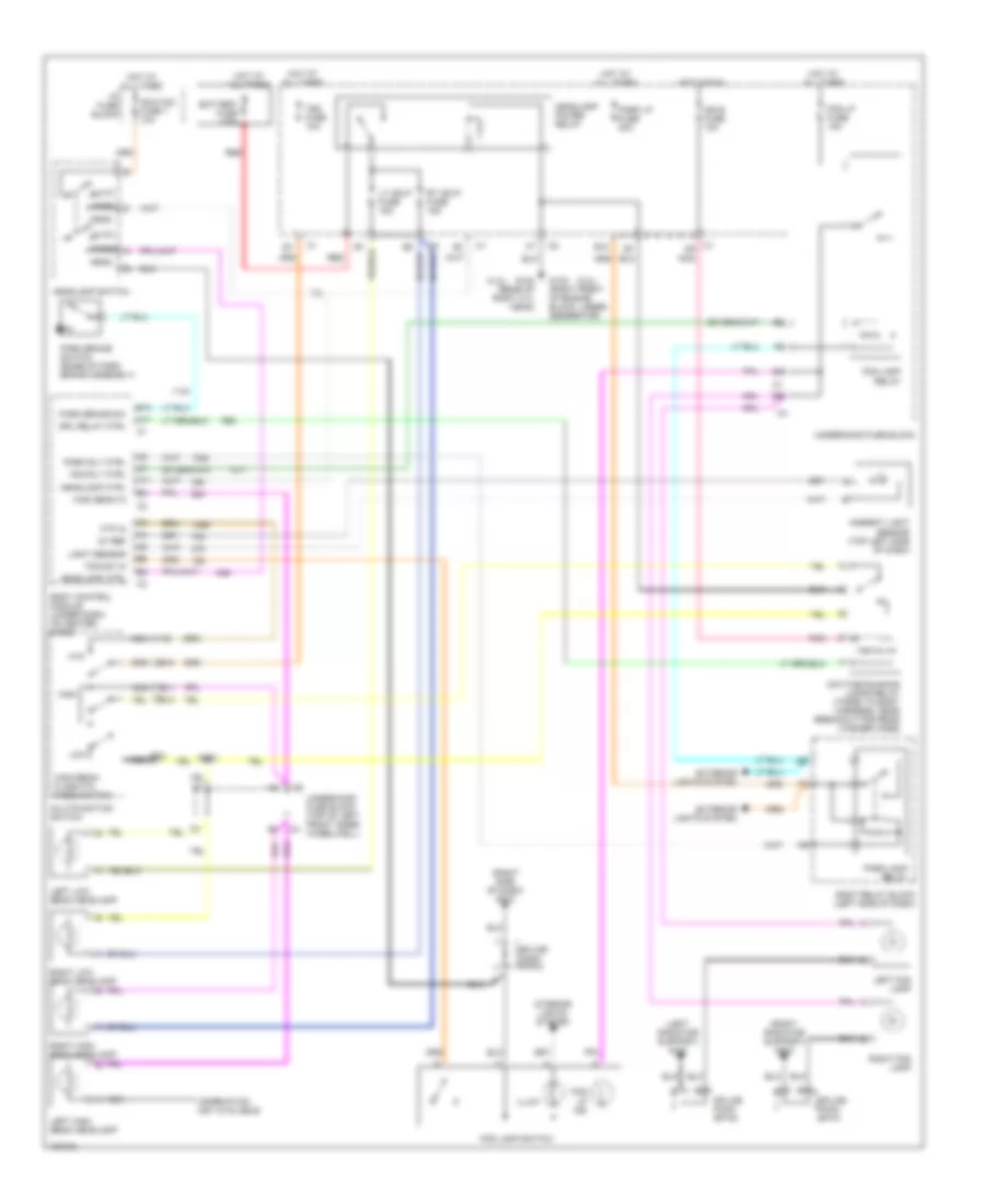
Headlights Wiring Diagram, without ZR2 for GMC Sonoma 2004
 https://portal-diagnostov.com/license.html
Automotive Electricians Portal FZCO
Automotive Electricians Portal FZCO
https://portal-diagnostov.com/license.html
https://portal-diagnostov.com/license.html
Automotive Electricians Portal FZCO
Automotive Electricians Portal FZCOList of elements for Headlights Wiring Diagram, without ZR2 for GMC Sonoma 2004:
- (2.2l)
- (4.3l)
- (left radiator support) g111
- (right radiator support) g112
- (right side of dash) g203
- 5v ref
- 87a
- A11
- Ambient light sensor (top left side of dash)
- Auto
- B10
- B12
- Battery fuse 175a
- Body control module (under dash, on heater case)
- Body relay block (left side of dash)
- C1 b12
- C11
- Daytime running lamps relay
- Drl relay ctrl
- E10
- E11
- E12
- E13
- Exterior lights system
- Fog lamp relay
- Fog lamp switch
- Fog lp fuse 15a
- Fog lp ind
- Fog rly ctrl
- Fog sw in
- Ftp
- Ftp in
- G102 (rear of right cyl head)
- G102 (right front of engine block, under generator)
- G200 (left side of dash)
- Hdlp
- Hdlp sw fuse 7 10a
- Headlamp ctrl
- Headlamp grounding relay
- Headlamp power relay
- Headlamp switch
- High
- High beam in
- High beam/ flash-to- pass switch
- Hot at all times
- I/p fuse block
- Illum
- Interior lights system
- Left fog lamp
- Left high beam headlamp
- Left low beam headlamp
- Light sensor
- Low
- Lt hdlp fuse 15a
- Multifunction switch
- Nca
- Park brake sw
- Park brake switch (base of park brake assembly)
- Park lamp relay
- Park lp fuse 20a
- Park rly ctrl
- Pklp
- Red
- Right fog lamp
- Right high beam headlamp
- Right low beam headlamp
- Rt hdlp fuse 15a
- Splice pack sp100
- Splice pack sp101
- Splice pack sp202 (left center of dash)
- Splice pack sp203
- Tbc fuse 10a
- Underhood fuse block
- Underhood fuse block (top of left front inner wheelwell)
HORN
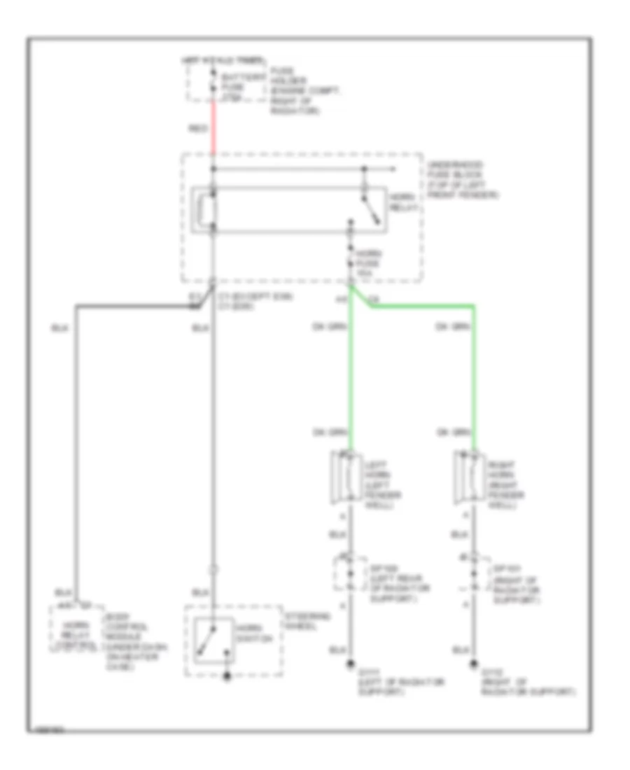
Horn Wiring Diagram for GMC Sonoma 2004
 https://portal-diagnostov.com/license.html
Automotive Electricians Portal FZCO
Automotive Electricians Portal FZCO
https://portal-diagnostov.com/license.html
https://portal-diagnostov.com/license.html
Automotive Electricians Portal FZCO
Automotive Electricians Portal FZCOList of elements for Horn Wiring Diagram for GMC Sonoma 2004:
- (except e09) (e09)
- (right of radiator support)
- Battery fuse 175a
- Body control module (under dash, on heater case)
- C1 c1
- E3 b2
- Fuse holder (engine compt, right of radiator)
- G111 (left of radiator support)
- G112 (right of radiator support)
- Horn fuse 15a
- Horn relay
- Horn relay control
- Horn switch
- Hot at all times
- Left horn (left fender well)
- Red
- Right horn (right fender well)
- Sp100 (left rear of radiator support)
- Sp101
- Steering wheel
- Underhood fuse block (top of left front fender)
INSTRUMENT CLUSTER
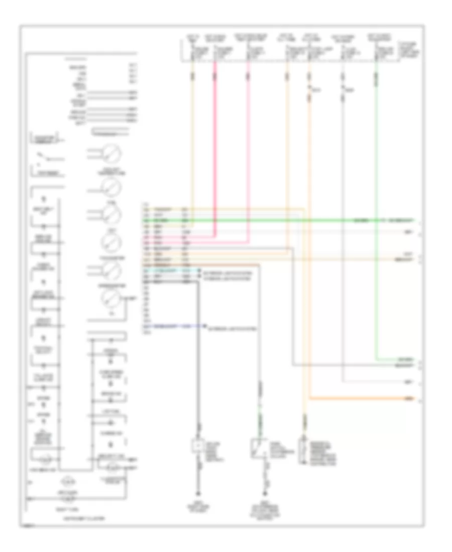
Instrument Cluster Wiring Diagram (1 of 2) for GMC Sonoma 2004
 https://portal-diagnostov.com/license.html
Automotive Electricians Portal FZCO
Automotive Electricians Portal FZCO
https://portal-diagnostov.com/license.html
https://portal-diagnostov.com/license.html
Automotive Electricians Portal FZCO
Automotive Electricians Portal FZCOList of elements for Instrument Cluster Wiring Diagram (1 of 2) for GMC Sonoma 2004:
- A10
- A11
- A12
- Air bag ind
- Anti-lock brakes ind
- B10
- B11
- B12
- Batt
- Brake ind
- Charge ind
- Check gauges ind
- Clstr fuse 11 10a
- Coolant temperature
- Cruise fuse 3 10a
- Ctsy lamp fuse 8 10a
- Eng spd
- Engine oil pressure sensor (top rear of engine, near distributor)
- Exterior lights system
- Fuel
- G203 (right side of dash)
- G207 (on steering column, near multi-function switch)
- Gauges fuse 4 10a
- Ground
- High beam ind
- Hot at all times
- Hot in accy, run or rap
- Hot in park or head
- Hot in run
- Hot in run or start
- Hot in run, bulb test or start
- I/p fuse block (left end of dash)
- Ign 1
- Ign 3
- Illum fuse 12 10a
- Illumination (6 bulb)
- Instrument cluster
- Interior lights system
- Left turn
- Low fuel
- Mil (service engine soon ind)
- Odometer display
- Off/run start
- Oil
- Over speed alarm ind
- P r n d 3 2 1
- Park sw
- Park switch (in steering column)
- Pnk
- Rdo batt fuse 19 15a
- Rdo ign fuse 24 10a
- Right turn
- S205
- S310
- Seat belt ind
- Security ind
- Serial data
- Service 4wd ind
- Spare
- Speedometer
- Splice pack sp203 (near ashtray)
- Tachometer
- Tail gate alarm ind
- Tow/haul ind (a/t)
- Trip reset
- Upshift ind (m/t)
- Volt
- Vss
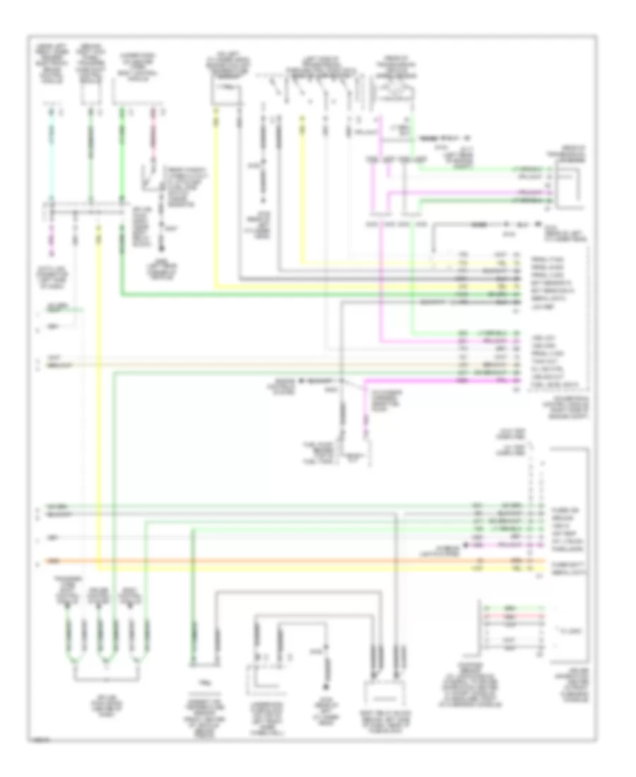
Instrument Cluster Wiring Diagram (2 of 2) for GMC Sonoma 2004
 https://portal-diagnostov.com/license.html
Automotive Electricians Portal FZCO
Automotive Electricians Portal FZCO
https://portal-diagnostov.com/license.html
https://portal-diagnostov.com/license.html
Automotive Electricians Portal FZCO
Automotive Electricians Portal FZCOList of elements for Instrument Cluster Wiring Diagram (2 of 2) for GMC Sonoma 2004:
- (behind right kick panel) transfer case shift control module
- (in chassis harness, near fuel pump)
- (left side of transmission) park/neutral position & back-up lamp switch
- (near left front inner fender) electronic brake control module
- (on left cylinder head) engine coolant temperature sensor
- (rear of transmission) c116 (m-m)
- (rear of transmission) vehicle speed sensor
- (under dash, on heater case) body control module
- (w/ trip computer)
- (w/o trip computer)
- 2wd
- 4wd
- A12
- Air temp
- Ambient air temperature sensor (front center of vehicle, behind fascia)
- B10
- Bare
- Body control module
- Body relay block (behind left side of dash, near i/p fuse block)
- Clr
- Compass sensor (w/ long console: integral to driver information center, w/ short console: in headliner, right of overhead console)
- Cruise control system
- Data link connector (left side of dash)
- Driver information center (in front overhead console)
- Ect sens sig in
- Ect sensor in
- Engine controls system
- Fuel level sig in
- Fuel pump/ sender (top of fuel tank)
- Fused batt
- Fused ign
- G104 (rear of left cylinder head)
- G105 (rear of left cylinder head)
- G117 (left rear of engine compt)
- G450 (left rear corner of vehicle)
- Ground
- Ic logic
- Int lite dim
- Interior lights system
- Low ref
- Mil ind ctrl
- Parklamps
- Powertrain control module (right side of engine compt)
- Prndl a sig
- Prndl b sig
- Prndl c sig
- Prndl p sig
- Rear window wiper cutout & liftglass ajar jamb switch (inside endgate)
- Red
- S134
- S140
- S152
- S422
- S427
- Serial data
- Splice pack sp200 (center of dash)
- Splice pack sp201 (near body relay block)
- Tach out
- Transfer case shift control module
- Underhood fuse block (on top of left front inner wheelwell)
- Vss high
- Vss in
- Vss low
- Vss sig out
INTERIOR LIGHTS
Courtesy Lamps Wiring Diagram (1 of 2) for GMC Sonoma 2004
 https://portal-diagnostov.com/license.html
Automotive Electricians Portal FZCO
Automotive Electricians Portal FZCO
https://portal-diagnostov.com/license.html
https://portal-diagnostov.com/license.html
Automotive Electricians Portal FZCO
Automotive Electricians Portal FZCOList of elements for Courtesy Lamps Wiring Diagram (1 of 2) for GMC Sonoma 2004:
- 2 door
- 2-door
- 4 door
- 4-door
- B10
- B11
- B12
- Body control module (under dash, on heater case)
- Body relay block (behind left side of dash, near i/p fuse block)
- C203
- Cargo lamp
- Courtesy lamp
- Courtesy lamp relay
- Ctsy lamp fuse 8 10a
- Ctsy lamp switch sig
- Dome lamp
- Dome lmp
- Dome override
- Dr handle
- Driver door jamb switch
- Driver door sw input
- Front passenger door jamb switch
- G200 (behind upper left end of dash)
- G203 (behind right side of dash)
- G203 (right side of dash)
- G205 (right side of dash)
- G405 (right rear body corner)
- Headlamp switch
- Hot at all times
- I/p fuse block (left end of dash)
- Inadvertent power
- Inadvertent power lamp relay
- Int lps detent switch sig c3
- Key buzzer
- Lamp request
- Left console courtesy lamp
- Left rear door jamb switch
- Liftgate jamb switch c2
- Not used
- Pickup only
- Rear window wiper cutout & liftgate ajar jamb switch
- Right console courtesy lamp
- Right door handle switch
- Right front door jamb c3 switch input
- Right rear door jamb switch
- S305 (body harn, in right rear door breakout)
- S427
- S601
- Secondary door latch switch sig
- Sp202
- Sp203
- Sp204
- Splice pack sp203
- Tan
- To dome lamp (diagram 2 of 2)
- To overhead console (diagram 2 of 2)
- To splice s300 (diagram 2 of 2)
- To splice s332 (diagram 2 of 2)
- W/ overhead console
- W/o overhead console
Courtesy Lamps Wiring Diagram (2 of 2) for GMC Sonoma 2004
 https://portal-diagnostov.com/license.html
Automotive Electricians Portal FZCO
Automotive Electricians Portal FZCO
https://portal-diagnostov.com/license.html
https://portal-diagnostov.com/license.html
Automotive Electricians Portal FZCO
Automotive Electricians Portal FZCOList of elements for Courtesy Lamps Wiring Diagram (2 of 2) for GMC Sonoma 2004:
- (dome lamp hard, 5 cm from visor vanity mirror lamp left) s310
- (w/ ec mirror) (w/o ec mirror)
- (w/o ec mirror) (w/ ec mirror)
- C301
- Center high mounted stop lamp
- Dome lamp
- Dome light
- Driver information display module
- From body relay block (diagram 1 0f 2)
- From body relay block (diagram 1 of 2)
- G202 (left front of dash)
- Inside rearview mirror or driver information display module
- Inside rearview mirror or driver information display w/o overhead console
- Left visor vanity mirror lamp
- Overhead console w/ sun roof
- Overhead console w/o sun roof
- Pickup
- Right visor vanity mirror lamp
- S300 (dome lamp hard, right front of roof)
- S300 (dome lamp hard, top of left "a" pillar)
- S302
- S310
- S332 (dome lamp hard, 7 cm from c300)
- Utility
- W/ full trip
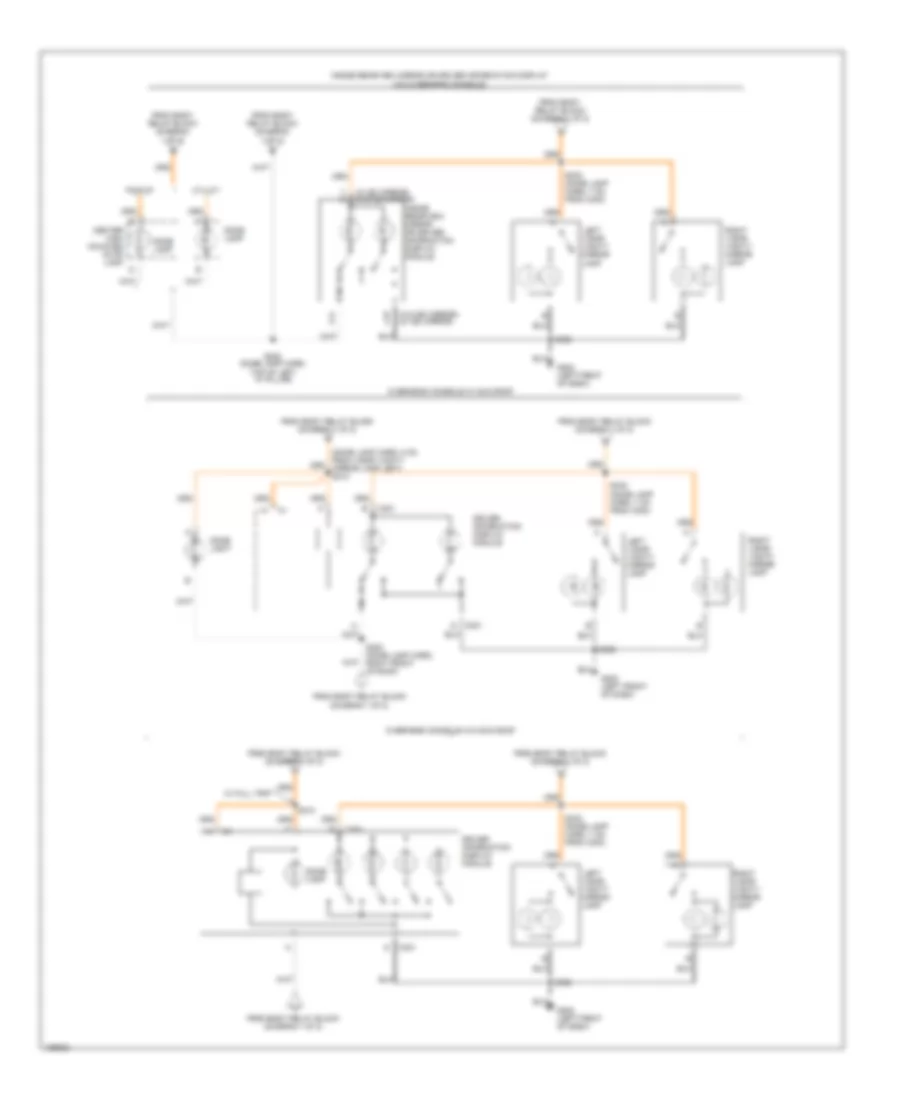
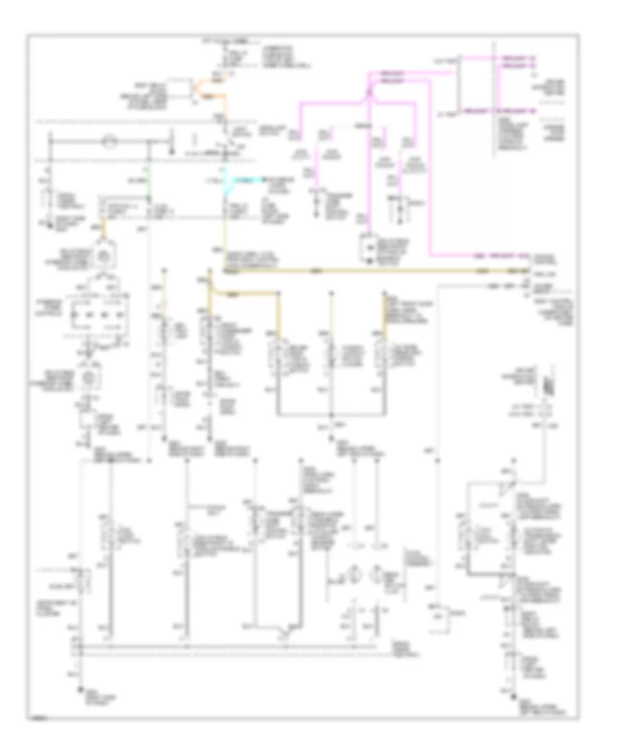
Instrument Illumination Wiring Diagram for GMC Sonoma 2004
 https://portal-diagnostov.com/license.html
Automotive Electricians Portal FZCO
Automotive Electricians Portal FZCO
https://portal-diagnostov.com/license.html
https://portal-diagnostov.com/license.html
Automotive Electricians Portal FZCO
Automotive Electricians Portal FZCOList of elements for Instrument Illumination Wiring Diagram for GMC Sonoma 2004:
- (4) bulbs
- (6) bulbs
- (right side of dash) g203
- (w/ trip)
- (w/o trip)
- 2wd pickup & utility
- 4wd pickup
- 4wd utility
- A12
- Ash tray lamp
- Automatic transmission shift lever position indicator
- B12
- Body control module (under dash, on heater case)
- Body relay block (behind left side of dash)
- Body relay block (behind left side of dash, near i/p fuse block)
- C10
- Dim
- Dimmer input c3
- Dimming control
- Driver door lock & window switch
- Driver information center
- Exterior lamps system
- Fog lamp switch
- Front passenger door lock & window switch
- G200 (behind upper left end of dash)
- G202 (behind upper left end of dash)
- G203 (behind right side of dash)
- G203 (right side of dash)
- G205 (behind right side of dash)
- Garage door opener
- Head
- Headlamp switch
- Hot at all times
- Hvac control assembly
- I/p fuse block (left side of dash)
- Illum fuse 12 10a
- Inflatable restraint i/p module disable switch
- Inflatable restraint steering wheel module coil
- Input dimmer
- Instrument panel cluster
- Light switch
- Off
- Outside rearview mirror switch
- Park
- Pickup only
- Prk lp fuse 20a
- Prk lp fuse 5 10a
- Prk lps
- Radio
- Rear def switch illum
- Rear wiper/ washer & endgate/ liftglass window release switch
- S205 (dash harn, 8 cm from radio breakout)
- S282
- S283
- S335 (floor shift extension harn, 7 cm from prndl lamp breakout)
- S336 (floor shift extension harn, 7 cm from prndl lamp breakout)
- S390 (dome lamp harness, 5 cm from console breakout)
- S501
- S502 (left front door harn, near breakout to radio speaker)
- S601 (crew cab only)
- Sp202 (left center of dash)
- Sp203 (near ashtray)
- Spice pack sp203
- Spice pack sp204
- Steering wheel controls
- Str whl ill fuse 6 2a
- Tow/ haul switch
- Transfer case shift control switch
- Underhood fuse block (top of left inner wheelwell)
- Utility
- W/ trip
- W/o trip
- Window lockout switch (4 door)
POWER DISTRIBUTION
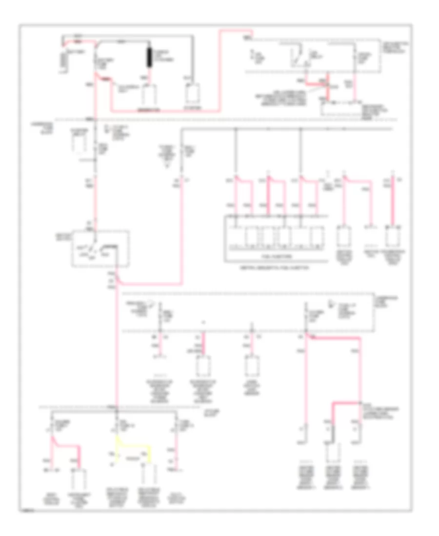
Power Distribution Wiring Diagram (1 of 5) for GMC Sonoma 2004
 https://portal-diagnostov.com/license.html
Automotive Electricians Portal FZCO
Automotive Electricians Portal FZCO
https://portal-diagnostov.com/license.html
https://portal-diagnostov.com/license.html
Automotive Electricians Portal FZCO
Automotive Electricians Portal FZCOList of elements for Power Distribution Wiring Diagram (1 of 5) for GMC Sonoma 2004:
- (air jumper harn, between g100 & breakout to eng harn, 5 cm from breakout to eng harn)
- (not used)
- A10
- Acc
- Air fuse 30a
- Air injection reactor fuse block
- Air relay
- Air sol fuse 30a
- B10
- B11
- Battery
- Battery fuse 175a
- Body control module
- C10
- California only
- Central sequential fuel injection
- D10
- E10
- Ecm 1 fuse 15a
- Eng 1 fuse 10a
- Evaporative emissions (evap) canister purge solenoid
- Evaporative emissions (evap) canister vent solenoid
- F10
- From ecm 1 a fuse diagram 1 of 5)
- Fuel injectors
- Fusible link (10 ga-red)
- Gauges fuse 4 10a
- Generator
- Heated oxygen sensor (ho2s) (bank 1 sensor 1)
- Heated oxygen sensor (ho2s) (bank 1 sensor 2)
- Heated oxygen sensor (ho2s) (bank 2 sensor 1)
- I/p fuse block
- Ign a fuse 40a
- Ignition coil
- Ignition control module (icm)
- Ignition switch
- Inflatable restraint i/p module disable switch
- Inflatable restraint sensing & diagnostic module
- Instrument panel cluster (ipc)
- Lock
- Mass air flow (maf) sensor
- Multi- function switch
- Nca
- Off
- Oxygen fuse 20a
- Pickup
- Pnk
- Powertrain control module (pcm)
- Red
- Run
- S100 (in oxygen sensor jumper harn, 36 cm from c100)
- S105
- Secondary air injection reactor pump
- Sir fuse 16 15a
- Start
- Starter
- Starter relay
- To b/u lp fuse (diagram 2 of 5)
- To eng 1 fuse (diagram 1 of 5)
- To ign c fuse (diagram 2 of 5)
- Turn fuse 10 20a
- Underhood fuse block
Power Distribution Wiring Diagram (2 of 5) for GMC Sonoma 2004
 https://portal-diagnostov.com/license.html
Automotive Electricians Portal FZCO
Automotive Electricians Portal FZCO
https://portal-diagnostov.com/license.html
https://portal-diagnostov.com/license.html
Automotive Electricians Portal FZCO
Automotive Electricians Portal FZCOList of elements for Power Distribution Wiring Diagram (2 of 5) for GMC Sonoma 2004:
- (body harn, 98 cm from rear doors breakout) s309
- (not used)
- (w/ automatic day/night mirror)
- 2 door
- 4 door
- A/c compressor clutch relay
- A/t
- Abs fuse 60a
- Acc
- Air relay
- Automatic transmission shift lock (btsi) solenoid (w/ floor shift a/t)
- B/u lp fuse 25a
- B11
- B12
- Back-up lamp switch
- Blower motor relay
- Body relay block
- Btsi fuse 10a
- C12
- D12
- Daytime running lamp (drl) relay
- Electronic brake control module (ebcm)
- From b/u lp fuse diagram 2 of 5)
- From ign a fuse diagram 1 of 5)
- From oxygen b fuse diagram 1 of 5)
- Haz lp fuse 20a
- Headlamp grounding relay
- Headlamp switch
- Hvac fuse 30a
- Ign b fuse 50a
- Ign c fuse 20a
- Ign e fuse 10a
- Ignition switch
- Inside rear view mirror (utility)
- Left back-up lamp (pickup)
- Left back-up lamp (utility)
- Lock
- M/t
- Multi- function switch
- Off
- Park lamp relay
- Park lp fuse 20a
- Park/ neutral position (pnp) switch
- Pnk
- Rear defogger relay (except base pickup)
- Red
- Right back-up lamp (pickup)
- Right back-up lamp (utility)
- Run
- Secondary air injection reactor fuse block (calif)
- Sp204 (center front of dash)
- Sp400 (center inside of rear crossmember) (pickup)
- Start
- Stop lamp switch
- Stud 2 fuse 30a
- To clstr fuse (diagram 4 of 5)
- To crank fuse (diagram 4 of 5)
- To ign e fuse (diagram 2 of 5)
- To rap maxi fuse (diagram 3 of 5)
- To rap relay (diagram 5 of 5)
- To s204 (diagram 5 of 5)
- Trailer wiring provisions
- Trailer wiring provisions (utility w/ m/t)
- Transfer case shift control module (np1)
- Trl b/u fuse 10a
- Underhood fuse block
- Veh b/u fuse 15a
- W/ zr2
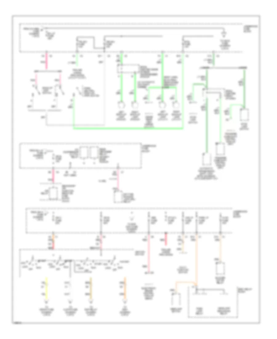
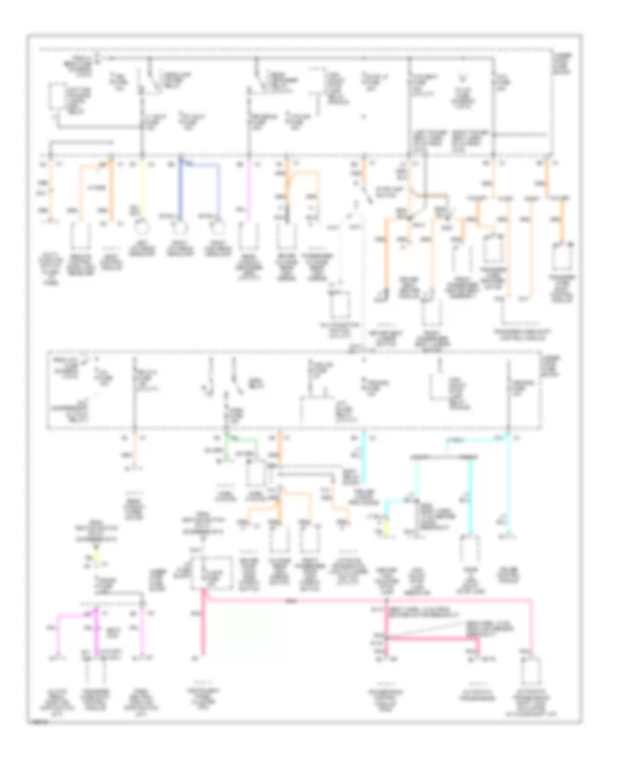
Power Distribution Wiring Diagram (3 of 5) for GMC Sonoma 2004
 https://portal-diagnostov.com/license.html
Automotive Electricians Portal FZCO
Automotive Electricians Portal FZCO
https://portal-diagnostov.com/license.html
https://portal-diagnostov.com/license.html
Automotive Electricians Portal FZCO
Automotive Electricians Portal FZCOList of elements for Power Distribution Wiring Diagram (3 of 5) for GMC Sonoma 2004:
- (pickup)
- (utility)
- 2 door
- 4 door
- Aux pwr fuse 25a
- Body relay block
- C301
- Cargo lamp (utility)
- Cigar lighter
- Cigar ltr fuse 15a
- Courtesy lamp breakout, 4 cm from breakout to lamp) s208
- Ctsy lp fuse 10a
- Data link connector (dlc)
- Daytime running lamp (drl) relay
- Dome lamp (utility) dome lamp & center high mounted stop lamp (pickup)
- Dome lamp (w/ sunroof)
- Dome lamp (w/o sunroof)
- Door lock relay
- Door unlock relay
- Driver information center (dic)
- Driver information center (dic) (w/o trip computer)
- Driver seat adjuster switch
- Driver seat lumbar switch
- Driver's door unlock relay
- Ecm b fuse 20a
- Fog lamp relay
- Fog lp fuse 15a
- From abs i fuse (diagram 2 of 5)
- From int bat fuse (diagram 3 of 5)
- From s223 diagram 3 of 5)
- Front passenger seat adjuster switch
- Fuel pump relay
- G203 (behind right side of dash, between c203 & splice packs)
- G204 (behind right side of dash, between c203 & splice pack)
- Garage door opener module
- Hdlp sw fuse 10a
- Headlamp switch
- I/p fuse block
- Inadvertent power lamp relay
- Instrument panel cluster (ipc)
- Int bat fuse 50a
- Left auxiliary power outlet
- Left console courtesy lamp
- Memory seat module
- Nca
- Power seats circuit breaker 25a (utility w/ power seat)
- Powertrain control module (pcm)
- Pwr lcks fuse 15a
- Radio
- Rap fuse 50a
- Rdo bat fuse 15a
- Red
- Right auxiliary power outlet
- Right console courtesy lamp
- S223
- S268 (auxiliary power tray harn, 9.5 cm from in-line dash connector)
- S269
- S304 (in body harn, before breakout to left & right rear door)
- S310
- S311 (in left power seat harn)
- Sp203 (in front of ashtray, strapped to body harn)
- To hi beam fuse (diagram 3 of 5)
- To pwr lcks fuse 14 (diagram 3 of 5)
- To rap relay (diagram 5 of 5)
- To tbc fuse (diagram 4 of 5)
- Transfer case shift control module (w/ np1)
- Under- hood fuse block
- Underhood fuse block
- Utility
- Utility w/ overhead trip console
- Utility w/o overhead console & pickup
- Utility w/overhead
- W/ memory
- W/o memory
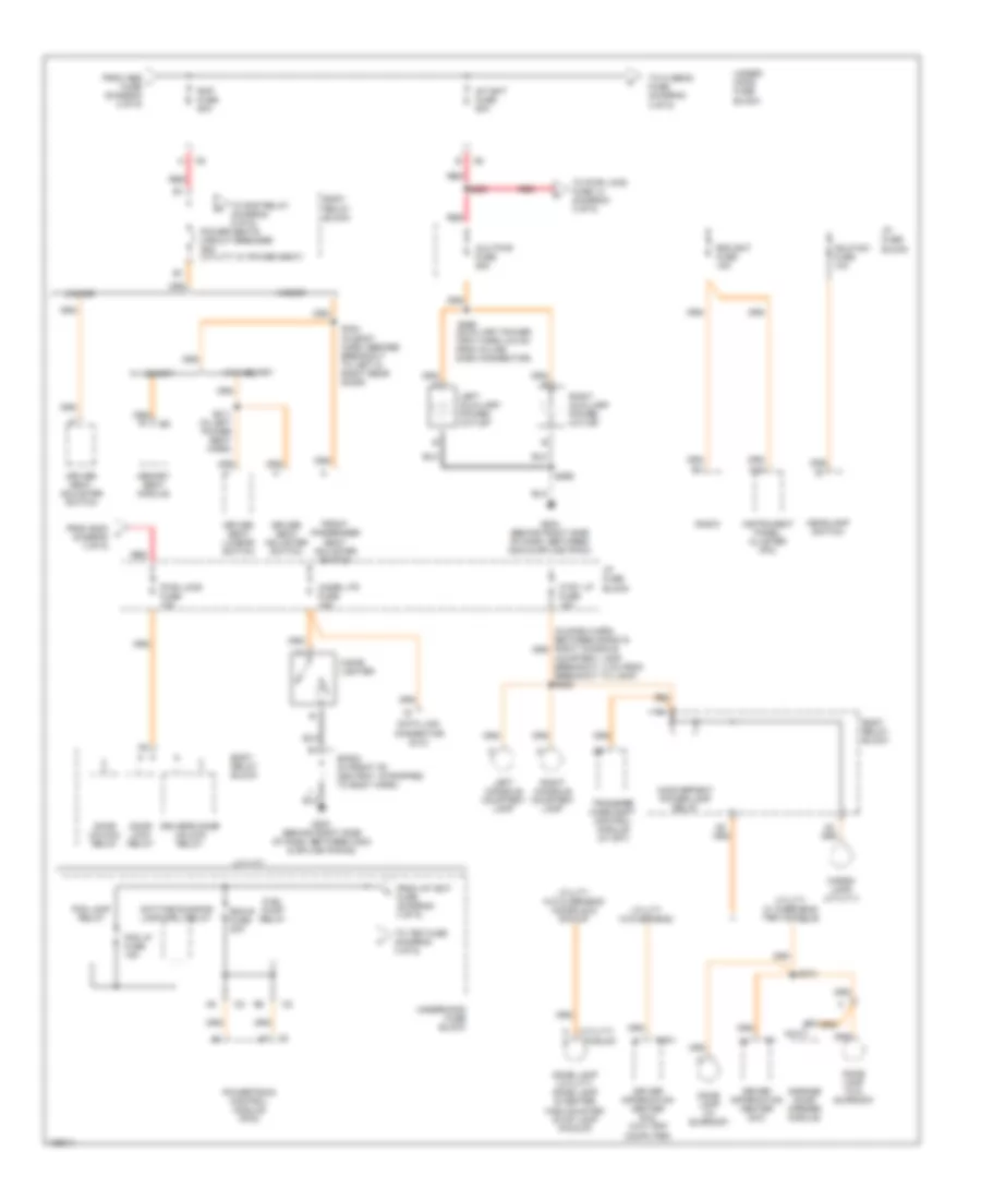
Power Distribution Wiring Diagram (4 of 5) for GMC Sonoma 2004
 https://portal-diagnostov.com/license.html
Automotive Electricians Portal FZCO
Automotive Electricians Portal FZCO
https://portal-diagnostov.com/license.html
https://portal-diagnostov.com/license.html
Automotive Electricians Portal FZCO
Automotive Electricians Portal FZCOList of elements for Power Distribution Wiring Diagram (4 of 5) for GMC Sonoma 2004:
- (body harn, 13 cm from blower motor breakout)
- (eng harn, 10 cm from map sensor breakout)
- (left power seat harn, 20 cm from c317)
- (right power seat harn, 20 cm from c315)
- (w/ np1)
- (w/o np1)
- A/c compressor clutch relay
- A/c fuse 10a
- Atc fuse 20a
- Automatic transmission
- Automatic transmission shift lock actuator (w/ floor shift a/t)
- Body control module
- Body relay block
- C1 a1
- C175
- Center high mounted stop lamp
- Clstr fuse 10a
- Clutch pedal position (cpp) switch (m/t)
- Crank fuse 10a
- Cruise control module
- D11
- D14
- D15
- D16
- Daytime running lamps (drl) relay
- Dome & high mount stop lamp
- Driver door lock/ side window switch
- Driver outside rear view mirror
- Driver seat heater module
- Driver seat lumbar switch
- E10
- E11
- E12
- Estc 4wd
- F10
- F11
- F12
- From atc m fuse (diagram 4 of 5)
- From hi beam fuse (diagram 3 of 5)
- From ignition switch pin c1 (diagram 2 of 5)
- From ignition switch pin d1 (diagram 2 of 5)
- Front passenger door lock/ window switch
- Front passenger heated seat assembly
- Front passenger seat lumbar switch
- Headlamp power relay
- High mount stop lamp relay (pickup)
- High mount stop lamp resistor
- Horn (a note)
- Horn (f note)
- Horn fuse 15a
- Horn relay
- Htd mir fuse 10a
- Htd seat fuse 20a (utility)
- I/p fuse block
- Instrument panel cluster (ipc)
- Left low beam headlamp
- Lift- glass relay (utility)
- Liftgate or endgate lock cylinder switch (utility)
- Lt hdlp fuse 15a
- Mir/lks fuse 3a
- Multi- function switch (flash to pass)
- Multifunction switch (utility)
- Nca
- Outside rear view mirror switch
- Park/ neutral position (pnp) switch (a/t)
- Passenger outside rear view mirror
- Pickup
- Pnk
- Powertrain control module (pcm)
- Rear defogger relay (utility)
- Rear window defogger grid (utility)
- Rear window wiper motor
- Remote control door lock receiver
- Right high beam headlamp
- Right low beam headlamp
- Rr defog fuse 30a
- Rr w/w fuse 15a (utility)
- Rt hdlp fuse 15a
- S113
- S116
- S314
- S321
- S405 (body harn, 10 cm before chmsl breakout)
- Stop lp fuse 20a
- Stoplamp switch
- Tbc fuse 10a
- To a/c fuse (diagram 4 of 5)
- Trailer wiring provisions
- Transfer case encoder motor
- Transfer case shift control module
- Trchmsl fuse 10a
- Under- hood fuse block
- Utility
- Vechmsl fuse 10a
- W/ rke
- W/np1
- W/o np1
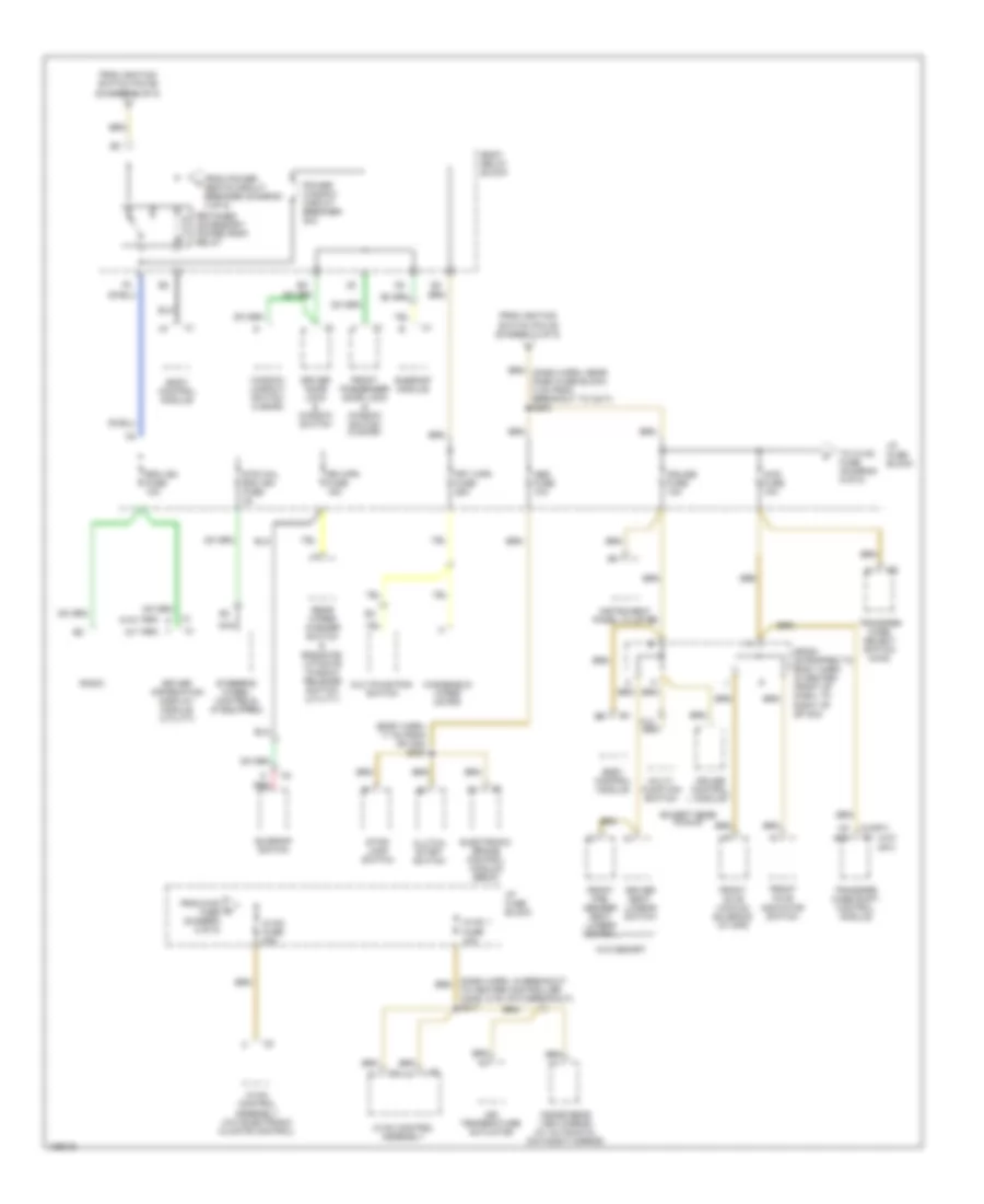
Power Distribution Wiring Diagram (5 of 5) for GMC Sonoma 2004
 https://portal-diagnostov.com/license.html
Automotive Electricians Portal FZCO
Automotive Electricians Portal FZCO
https://portal-diagnostov.com/license.html
https://portal-diagnostov.com/license.html
Automotive Electricians Portal FZCO
Automotive Electricians Portal FZCOList of elements for Power Distribution Wiring Diagram (5 of 5) for GMC Sonoma 2004:
- (body harn, 17 cm from sp 202) s203
- (dash harn, in breakout to heater controller conn, 6 cm into breakout) s217
- (w/ trip)
- (w/np1)
- (w/o np1)
- (w/o trip)
- 4wd fuse 10a
- Abs fuse 10a
- Air temperature actuator
- Body control module
- Body relay block
- C8 e10
- Clutch start switch
- Cruise control module
- Cruise fuse 10a
- Driver door lock & window switch
- Driver information display module (utility)
- Driver seat lumbar switch
- Electronic brake control module (ebcm)
- Except base pickup
- From 4wd fuse (diagram 5 of 5)
- From ignition switch pin c6 (diagram 2 of 5)
- From ignition switch pin d6 (diagram 2 of 5)
- From power seats circuit breaker (diagram 3 of 5)
- Front axle indicator switch
- Front axle vacuum solenoid (w/ np8)
- Front pas- senger seat lumbar switch
- Front passenger door lock & window switch (2 door)
- Frt wpr fuse 25a
- Hvac 1 fuse 10a
- Hvac control assembly
- Hvac control assembly (w/o electronic climate control)
- Hvac fuse 20a
- I/p fuse block
- Inside rear view mirror (w/ automatic day/night mirror)
- Instrument panel cluster
- Multi- function switch
- Multifunction switch
- Nca
- Power window circuit breaker 30a
- Radio
- Rdo ign fuse 10a
- Rear wiper/ washer switch & endgate/ liftgate window release switch (utility)
- Red
- Retained accessory power (rap) relay
- Rr wpr fuse 15a
- Sp200 (strapped to body harn, in center front of dash, to right of sp 204)
- Steering wheel controls (if equipped)
- Stop- lamp switch
- Str whl rdo ign fuse 2a
- Sunroof module
- Sunroof switch
- To hvac fuse (diagram 5 of 5)
- Transfer case select switch (4wd)
- Transfer case shift control module
- W/o memory
- Window lockout switch (4 door)
- Windshield wiper motor
POWER DOOR LOCKS
Power Door Locks Wiring Diagram for GMC Sonoma 2004
 https://portal-diagnostov.com/license.html
Automotive Electricians Portal FZCO
Automotive Electricians Portal FZCO
https://portal-diagnostov.com/license.html
https://portal-diagnostov.com/license.html
Automotive Electricians Portal FZCO
Automotive Electricians Portal FZCOList of elements for Power Door Locks Wiring Diagram for GMC Sonoma 2004:
- (body harn, 6.5 cm from right rear door jamb sw breakout) s307
- 87a
- A5 c1
- B11
- Battery
- Body control module (under dash, on heater case)
- Body relay block (behind left side of dash, near i/p fuse block)
- C211
- D10
- Door lock relay
- Door unlock relay
- Dr lk rly
- Dr unlk rly
- Driver door lock & window switch
- Driver door lock actuator
- Driver door unlock relay
- Drv dr unlk rly
- E10
- E11
- E12
- F10
- F12
- Front passenger door lock & window switch
- Front passenger door lock actuator
- G105 (left rear of cylinder head)
- G202 (behind upper left end of dash)
- Ground
- Hot at all times
- I/p fuse block (left end of dash)
- Ign key switch
- Ignition key alarm switch
- Instrument cluster system
- Left rear door lock actuator (utility)
- Liftgate/endgate lock cylinder switch (utility w/ content theft)
- Lock
- Mir/lck fuse 7 3a
- Mirrors system
- Pwr lks fuse 14 15a
- Remote control door lock receiver (behind lower left side of dash)
- Rfa link
- Right rear door lock actuator (utility)
- S308 (body harn, 16.5 cm from left rear door jamb sw breakout)
- Splice pack sp202 (left center of dash)
- Tan
- Tan b4
- Trc fuse 10a
- Underhood fuse block (top of left front inner wheelwell)
- Unlock
- Vss
- W/ keyless entry
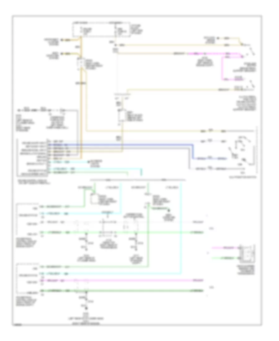
POWER MIRRORS
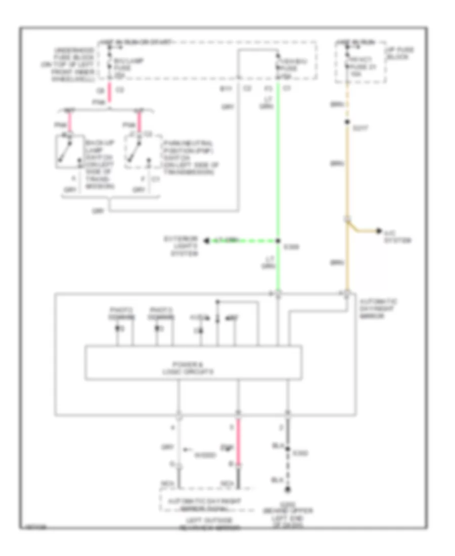
Electrochromic Mirror Wiring Diagram for GMC Sonoma 2004
 https://portal-diagnostov.com/license.html
Automotive Electricians Portal FZCO
Automotive Electricians Portal FZCO
https://portal-diagnostov.com/license.html
https://portal-diagnostov.com/license.html
Automotive Electricians Portal FZCO
Automotive Electricians Portal FZCOList of elements for Electrochromic Mirror Wiring Diagram for GMC Sonoma 2004:
- A/c system
- A/t
- Auto
- Automatic day/night mirror
- Automatic day/night mirror signal
- B/u lamp fuse 25a
- B11
- Back-up lamp switch (on left side of trans- mission)
- C1 f
- Exterior lights system
- G202 (behind upper left end of dash)
- Hot in run
- Hot in run or start
- Hvac1 fuse 21 10a
- I/p fuse block
- Left outside rearview mirror
- M/t
- Nca
- Off
- Park/neutral position (pnp) switch (on left side of transmission)
- Photo sensor
- Pnk
- Power & logic circuits
- S217
- S302
- S309
- Underhood fuse block (on top of left front inner wheelwell)
- Veh b/u fuse 15a
- W/ddo
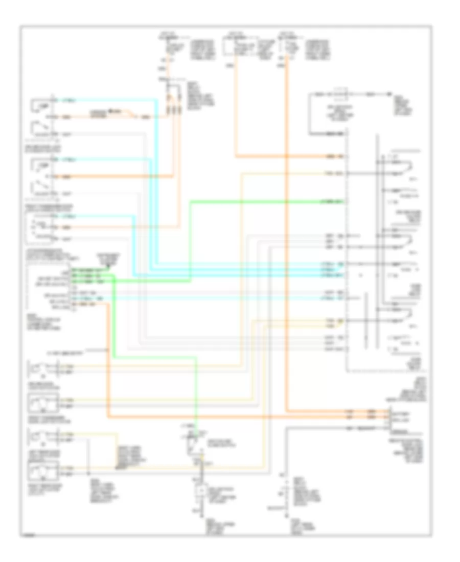
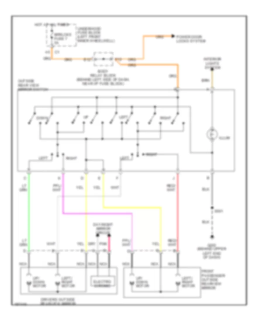
Power Mirrors Wiring Diagram for GMC Sonoma 2004
 https://portal-diagnostov.com/license.html
Automotive Electricians Portal FZCO
Automotive Electricians Portal FZCO
https://portal-diagnostov.com/license.html
https://portal-diagnostov.com/license.html
Automotive Electricians Portal FZCO
Automotive Electricians Portal FZCOList of elements for Power Mirrors Wiring Diagram for GMC Sonoma 2004:
- Body relay block (behind left side of dash, near i/p fuse block)
- Day/night mirror circuit
- Down
- Drivers outside rearview mirror
- E12
- Electro chromic
- F12
- Front passenger outside rearview mirror
- G202 (behind upper left end of dash)
- Hot at all times
- Illum
- Interior lights system
- Left
- Left/ right m
- Mir/lcks fuse 7 5a
- Motor
- Nca
- Outside rear view mirror switch
- Pnk
- Power door locks system
- Right
- S501
- Underhood fuse block (left front inner wheelwell)
- Up/ down m
POWER SEATS
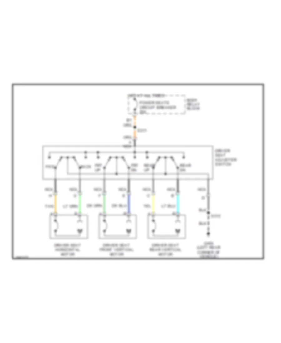
6-Way Power Seat Wiring Diagram for GMC Sonoma 2004
 https://portal-diagnostov.com/license.html
Automotive Electricians Portal FZCO
Automotive Electricians Portal FZCO
https://portal-diagnostov.com/license.html
https://portal-diagnostov.com/license.html
Automotive Electricians Portal FZCO
Automotive Electricians Portal FZCOList of elements for 6-Way Power Seat Wiring Diagram for GMC Sonoma 2004:
- A nca
- Back
- Body relay block
- Driver seat adjuster switch
- Driver seat front vertical motor
- Driver seat horizontal motor
- Driver seat rear vertical motor
- Frt dn
- Frt up
- Fwd
- G450 (left rear corner of vehicle)
- Hot at all times
- Nca
- Power seats circuit breaker 25a
- Rear dn
- Rear up
- S311
- S313
- Tan
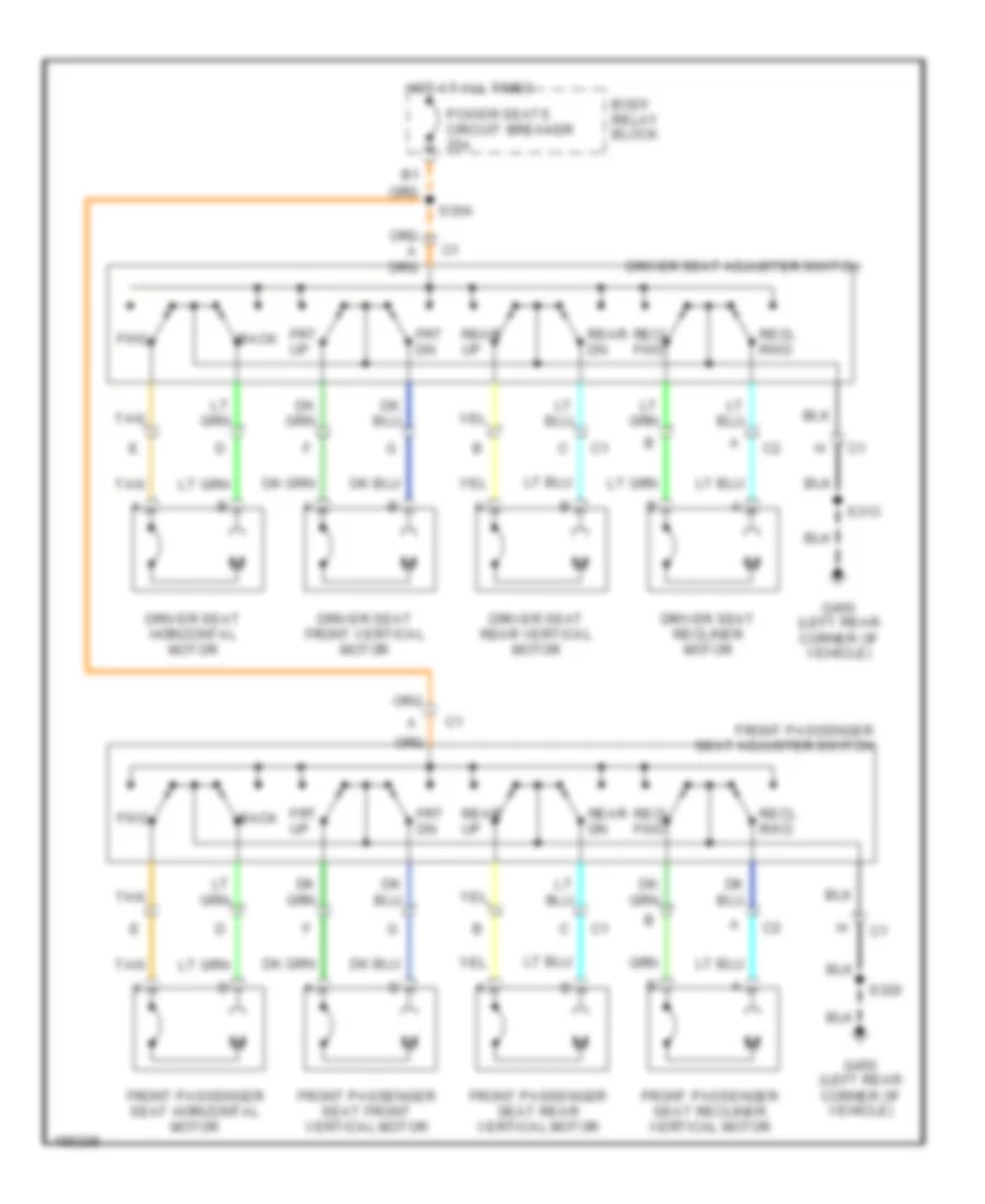
8-Way Adjustable Power Seat Wiring Diagram for GMC Sonoma 2004
 https://portal-diagnostov.com/license.html
Automotive Electricians Portal FZCO
Automotive Electricians Portal FZCO
https://portal-diagnostov.com/license.html
https://portal-diagnostov.com/license.html
Automotive Electricians Portal FZCO
Automotive Electricians Portal FZCOList of elements for 8-Way Adjustable Power Seat Wiring Diagram for GMC Sonoma 2004:
- Back
- Body relay block
- Driver seat adjuster switch
- Driver seat front vertical motor
- Driver seat horizontal motor
- Driver seat rear vertical motor
- Driver seat recliner motor
- Front passenger seat adjuster switch
- Front passenger seat front vertical motor
- Front passenger seat horizontal motor
- Front passenger seat rear vertical motor
- Front passenger seat recliner vertical motor
- Frt dn
- Frt up
- Fwd
- G450 (left rear corner of vehicle)
- Hot at all times
- Power seats circuit breaker 25a
- Rear dn
- Rear up
- Recl fwd
- Recl rwd
- S304
- S313
- S320
- Tan
Heated Seats Wiring Diagram for GMC Sonoma 2004
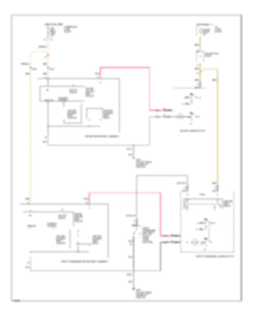 https://portal-diagnostov.com/license.html
Automotive Electricians Portal FZCO
Automotive Electricians Portal FZCO
https://portal-diagnostov.com/license.html
https://portal-diagnostov.com/license.html
Automotive Electricians Portal FZCO
Automotive Electricians Portal FZCOList of elements for Heated Seats Wiring Diagram for GMC Sonoma 2004:
- Cruise fuse 3 10a
- Driver heated seat assembly
- Driver heated seat module
- Driver lumbar switch
- Element control
- Front passenger heated seat assembly
- Front passenger lumbar switch
- Front passenger seat belt switch (open when buckled)
- G450 (on left rear corner of vehicle)
- Ground
- Heated seat relay
- Heater element seat back
- Heater element seat cushion
- Hot at all time
- Hot in run
- Htd seat fuse 20a
- I/p fuse block
- Nca
- Off
- Pnk
- S313
- S314
- S320
- S321
- Splice pack sp200
- Switch signal
- Underhood fuse block
POWER WINDOWS
Power Windows Wiring Diagram, 4 Door for GMC Sonoma 2004
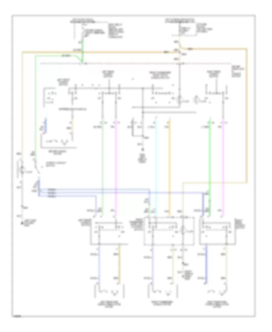 https://portal-diagnostov.com/license.html
Automotive Electricians Portal FZCO
Automotive Electricians Portal FZCO
https://portal-diagnostov.com/license.html
https://portal-diagnostov.com/license.html
Automotive Electricians Portal FZCO
Automotive Electricians Portal FZCOList of elements for Power Windows Wiring Diagram, 4 Door for GMC Sonoma 2004:
- (left side of dash) g202
- (right side of dash) g205
- Body relay block (behind left side of dash, near i/p fuse block)
- C1 k
- C2 b
- Driver door lock & window switch
- Driver window motor
- Express down module
- Front passenger door lock & window switch
- Front passenger window motor
- G202 (left side of dash)
- Hot in acc, run & retained acc power
- Hot w/headlamp switch in park or head position
- I/p fuse block (on left end of dash)
- Illum
- Left front window switch
- Left rear side window regulator motor
- Left rear window switch
- Park lp fuse 5 10a
- Power window circuit breaker 30a
- Right rear side window regulator motor
- Right rear window switch
- S306
- S501
- S502
- S601
- Tan
- Window lockout switch
RADIO
Radio Wiring Diagram, with Amplifier, Except Crew Cab for GMC Sonoma 2004
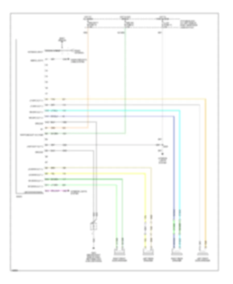 https://portal-diagnostov.com/license.html
Automotive Electricians Portal FZCO
Automotive Electricians Portal FZCO
https://portal-diagnostov.com/license.html
https://portal-diagnostov.com/license.html
Automotive Electricians Portal FZCO
Automotive Electricians Portal FZCOList of elements for Radio Wiring Diagram, with Amplifier, Except Crew Cab for GMC Sonoma 2004:
- A10
- A11
- A12
- Antenna input
- B10
- B11
- B12
- Body ground
- Coaxial cable
- Computer data lines system
- G203 (behind right side of dash, between c203 & splice packs)
- Ground
- Hot at all times
- Hot in acc or run
- Hot in park & head
- I/p fuse block (at left side of dash, near door jamb switch)
- Illum ifuse 12 10a
- Interior lights system
- Lamp sup volt 2
- Led dimming signal
- Left front door speaker
- Left rear speaker
- Lf spk out (+)
- Lf spk out (-)
- Lr spkr out (+)
- Lr spkr out (-)
- Radio
- Radio antenna
- Rap fuse sup voltage
- Rdo batt fuse 19 15a
- Rdo ign fuse 24 10a
- Rf spkr out (+)
- Rf spkr out (-)
- Right front door speaker
- Right rear speaker
- Rr spk out (+)
- Rr spk out (-)
- S205
- Serial data
- Tan
Radio Wiring Diagram, without Amplifier, Crew Cab for GMC Sonoma 2004
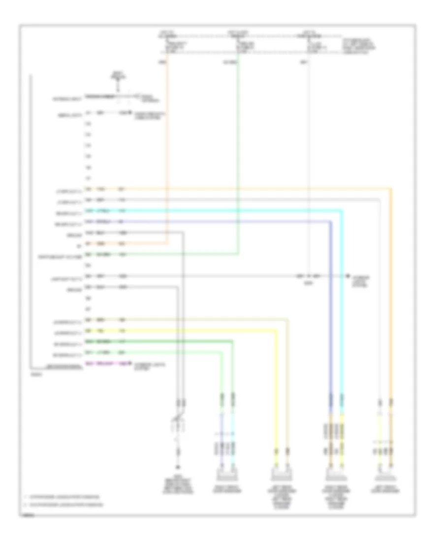 https://portal-diagnostov.com/license.html
Automotive Electricians Portal FZCO
Automotive Electricians Portal FZCO
https://portal-diagnostov.com/license.html
https://portal-diagnostov.com/license.html
Automotive Electricians Portal FZCO
Automotive Electricians Portal FZCOList of elements for Radio Wiring Diagram, without Amplifier, Crew Cab for GMC Sonoma 2004:
- (2 door)
- (4 door)
- (w/o pwr door locks & pwr windows)
- (w/pwr door locks & pwr windows)
- A10
- A11
- A12
- Antenna input
- B10
- B11
- B12
- Body ground
- Coaxial cable
- Computer data lines system
- G203 (behind right side of dash, between c203 & splice packs)
- Ground
- Hot at all times
- Hot in acc or run
- Hot in park & head
- I/p fuse block (at left side of dash, near door jamb switch)
- Illum ifuse 12 10a
- Interior lights system
- Lamp sup volt 2
- Led dimming signal
- Left front door speaker
- Left rear door speaker (4 door) left rear speaker (2 door)
- Lf spk out (+)
- Lf spk out (-)
- Lr spkr out (+)
- Lr spkr out (-)
- Radio
- Radio antenna
- Rap fuse sup voltage
- Rdo batt fuse 19 15a
- Rdo ign fuse 24 10a
- Rf spkr out (+)
- Rf spkr out (-)
- Right front door speaker
- Right rear door speaker (4 door) right rear speaker (2 door)
- Rr spk out (+)
- Rr spk out (-)
- S205
- Serial data
- Tan
SHIFT INTERLOCK
Shift Interlock Wiring Diagram, with Column Shift for GMC Sonoma 2004
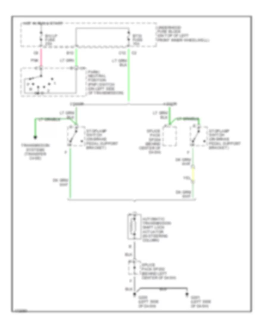 https://portal-diagnostov.com/license.html
Automotive Electricians Portal FZCO
Automotive Electricians Portal FZCO
https://portal-diagnostov.com/license.html
https://portal-diagnostov.com/license.html
Automotive Electricians Portal FZCO
Automotive Electricians Portal FZCOList of elements for Shift Interlock Wiring Diagram, with Column Shift for GMC Sonoma 2004:
- 2 door
- 4 door
- Automatic transmission shift lock actuator (in steering column)
- B/u lp fuse 25a
- B12
- Btsi fuse 10a
- C12
- G200 (left side of dash)
- G201 (left side of dash)
- Hot in run & start
- Park/ neutral position (pnp) switch (on left side of transmission)
- Pnk
- Splice pack sp202 (behind left center of dash)
- Splice pack sp204 (behind center of dash)
- Stoplamp switch (on brake pedal support bracket)
- Transmission systems (transfer case)
- Underhood fuse block (on top of left front inner wheelwell)
STARTING/CHARGING
Charging Wiring Diagram for GMC Sonoma 2004
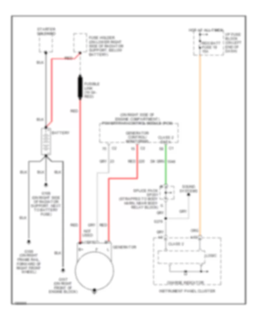 https://portal-diagnostov.com/license.html
Automotive Electricians Portal FZCO
Automotive Electricians Portal FZCO
https://portal-diagnostov.com/license.html
https://portal-diagnostov.com/license.html
Automotive Electricians Portal FZCO
Automotive Electricians Portal FZCOList of elements for Charging Wiring Diagram for GMC Sonoma 2004:
- (on right side of engine compartment) powertrain control module (pcm)
- A10
- Battery
- Charge indicator
- Class 2
- Class 2 data
- Fuse holder (on lower right side of radiator support, below battery)
- Fusible link (10 ga- red)
- G106 (on right frame rail, forward of right front wheel)
- G107 (on right front of engine block)
- G108 (on right side of radiator support, next to battery fuse)
- Generator control/ monitoring
- Generator l
- Hot at all times
- I/p fuse block (on left end of dash)
- Instrument panel cluster
- Logic
- Not used
- Rdo batt fuse 19 15a
- Red
- S276
- Sound systems
- Splice pack sp201 (strapped to body harn, near body relay block)
- Starter solenoid
Starting Wiring Diagram for GMC Sonoma 2004
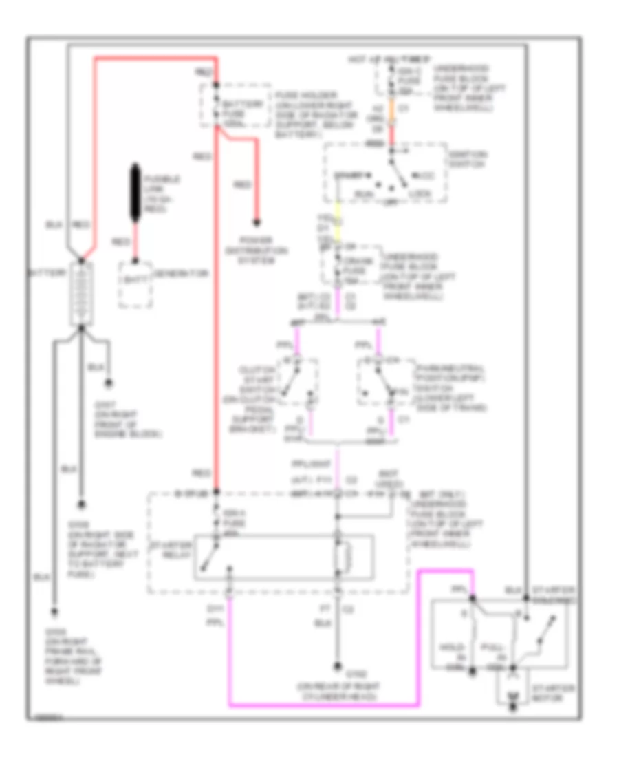 https://portal-diagnostov.com/license.html
Automotive Electricians Portal FZCO
Automotive Electricians Portal FZCO
https://portal-diagnostov.com/license.html
https://portal-diagnostov.com/license.html
Automotive Electricians Portal FZCO
Automotive Electricians Portal FZCOList of elements for Starting Wiring Diagram for GMC Sonoma 2004:
- (a/t)
- (m/t only)
- (m/t)
- (m/t) (a/t)
- (not used)
- (on rear of right cylinder head)
- A/t
- A11
- Acc
- B stud
- Batt
- Battery
- Battery fuse 175a
- C1 c2
- C3 e2
- Clutch start switch (on clutch pedal support bracket)
- Crank fuse 10a
- D11
- F11
- Fuse holder (on lower right side of radiator support, below battery)
- Fusible link (10 ga- red)
- G102
- G106 (on right frame rail, forward of right front wheel)
- G107 (on right front of engine block)
- G108 (on right side of radiator support, next to battery fuse)
- Generator
- Hold- in coil
- Hot at all times
- Ign a fuse 40a
- Ign c fuse 20a
- Ignition switch
- Lock
- M/t
- Off
- P/n
- Park/neutral position (pnp) switch (lower left side of trans)
- Power distribution system
- Pull- in coil
- Red
- Run
- Start
- Starter motor
- Starter relay
- Underhood fuse block (on top of left front inner wheelwell)
SUPPLEMENTAL RESTRAINTS
Supplemental Restraints Wiring Diagram for GMC Sonoma 2004
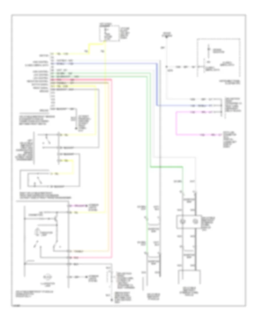 https://portal-diagnostov.com/license.html
Automotive Electricians Portal FZCO
Automotive Electricians Portal FZCO
https://portal-diagnostov.com/license.html
https://portal-diagnostov.com/license.html
Automotive Electricians Portal FZCO
Automotive Electricians Portal FZCOList of elements for Supplemental Restraints Wiring Diagram for GMC Sonoma 2004:
- (at right frame rail, forward of right front wheel) g101
- (behind right side of dash, between c203 & splice pack) g203
- (no connection)
- A10
- A11
- A12
- A13
- A14
- A15
- A16
- A17
- A18
- Air bag indicator
- Class 2 serial data
- Data link connector (dlc) (partial) (under left side of dash)
- Front signal
- Ground
- High control
- Hot in run & start
- I/p fuse block (on left end of dash)
- Ign
- Ignition
- Illumination lamp
- Indicator control
- Indicator lamp
- Inflatable restraint ip module
- Inflatable restraint ip module disable switch (pickup only)
- Inflatable restraint sensing & diagnostic module (under console & carpet, between front seats)
- Inflatable restraint steering wheel module
- Inflatable restraint steering wheel module coil
- Instrument panel cluster (ipc)
- Interior lights system
- Left inflatable restraint front end discriminating sensor (on left side of front frame crossmember)
- Low control
- Nca
- Pnk
- Right inflatable restraint front end discriminating sensor (on right side of front frame crossmember)
- S276
- Shorting bar
- Sir fuse 15a
- Sound systems
- Splice pack sp201 (strapped to body harn, near body relay block)
- Splice pack sp203 (in dash harn, in front of ashtray, strapped to body harness)
- Switch signal
TRANSMISSION
A/T Wiring Diagram for GMC Sonoma 2004
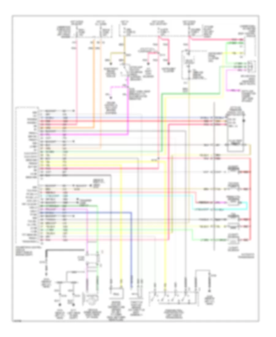 https://portal-diagnostov.com/license.html
Automotive Electricians Portal FZCO
Automotive Electricians Portal FZCO
https://portal-diagnostov.com/license.html
https://portal-diagnostov.com/license.html
Automotive Electricians Portal FZCO
Automotive Electricians Portal FZCOList of elements for A/T Wiring Diagram for GMC Sonoma 2004:
- (rear of right cyl head) g103
- (under dash, on heater case) body control module
- +5v
- 1-2 shift solenoid
- 1-2 ss
- 2-3 shift solenoid
- 2-3 ss
- 2wd
- 3-2 shift solenoid
- 3-2 ss
- 4wd
- 4wd low
- A/t fluid pressure manual valve position switch
- A/t shift lock solenoid
- A10
- A11
- A12
- Abs fuse 22 10a
- Automatic transmission
- B c2
- B8 c2
- Bare
- Blower motor resistor)
- Brk sw
- C116a (4wd)
- Cls 2 data
- Clstr fuse 11 10a
- Cruise control & anti-lock brakes systems
- D3, d2
- D4, d2
- Data link connector (under left side of dash)
- Ecm b fuse 20a
- Ecm i fuse 15a
- Ect sig
- Electronic brake control module
- Engine coolant temperature sensor (on left cylinder head, between rear plugs)
- Fluid temp sensor
- Frt axle sw
- G104 (rear of left cyl head)
- G104 rear of left cyl head)
- G105 (rear of left cyl head)
- G117 (left rear of eng compt)
- Gauges fuse 4 10a
- Gnd
- Hot at all times
- Hot in off, run, or start
- Hot in run
- Hot in run or start
- I/p fuse block (on left end of dash)
- Ign
- Instrument cluster
- Instrument panel cluster (ipc)
- Lo ref
- Mil (service engine soon ind)
- Mil ctrl
- Nca
- Park/neutral position switch (left side of transmission)
- Pc sol hi
- Pc sol lo
- Pnk
- Powertrain control module (right side of engine compt)
- Press ctrl solenoid
- Prnd a
- Prnd b
- Prnd c
- Prnd p
- Range b
- Range c
- Red
- Red a
- Red b
- Rev, lo
- S106
- S113
- S116
- S134
- S140
- S152
- S203
- Sens gnd
- Solid state
- Splice pack sp201 (near body relay block)
- Stoplamp switch (on brake pedal support bracket)
- Tan
- Tcc pwm
- Tcc pwm solenoid
- Tcc sol
- Tcc solenoid
- Tft sens sig
- Throttle position sensor (on throttle body assembly)
- Tp sig
- Trans rng a
- Transfer case circuit
- Underhood fuse block (on top of left front fender)
- Utility w/ floor shift
- Vehicle speed sensor (right rear of trans)
- Vss hi
- Vss lo
Transfer Case Wiring Diagram, with 2-Speed Automatic Transfer Case for GMC Sonoma 2004
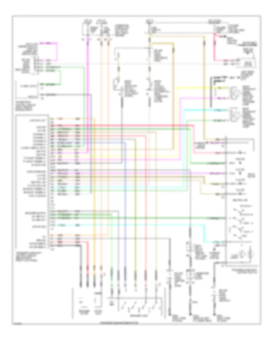 https://portal-diagnostov.com/license.html
Automotive Electricians Portal FZCO
Automotive Electricians Portal FZCO
https://portal-diagnostov.com/license.html
https://portal-diagnostov.com/license.html
Automotive Electricians Portal FZCO
Automotive Electricians Portal FZCOList of elements for Transfer Case Wiring Diagram, with 2-Speed Automatic Transfer Case for GMC Sonoma 2004:
- (left rear of engine compt) g117
- +8v ref
- +8v ref out
- 2-hi ind
- 4-hi ind
- 4-lo ind
- 4wd fuse 15 10a
- 4wd ind
- 4wd lo
- 4wd lo ind sig
- 4wd sw sig
- Atc fuse 20a
- Axle sw sig
- Bare
- Body control module
- Body relay block (behind left side of dash)
- C1 e5
- Channel-a
- Channel-b
- Channel-c
- Channel-p
- Class ii data
- Class ii serial data
- Clutch sol sig
- Crank fuse 10a
- Data link connector (dlc) (partial) (under left side of dash)
- Decoder logic
- E10
- E11
- E12
- E13
- E14
- E15
- E16
- Encoder motor
- Encoder sig rtn
- F10
- F11
- F12
- F13
- F14
- F15
- F16
- Front axle indicator switch (on front axle, right of diff)
- Front axle vacuum solenoid (on firewall, near windshield wiper motor)
- Front propshaft speed sensor (top left rear of transfer case
- Ft shaft speed hi
- Ft shaft speed lo
- Fwd
- G105 (rear of left cylinder head)
- G203 (right side of dash)
- G205 (right side of dash)
- Gauges fuse 4 10a
- Gnd
- Ground
- Hot at all times
- Hot in run
- Hot in run or start
- Hot in start
- I/p fuse block (on left end of dash)
- Ignition
- Illum lamps
- Instrument panel cluster
- Interior lights system
- Lock sol out
- Module ground
- Motor feed a
- Motor feed b
- Motor lock
- Nca
- Neutral ind
- Pnk
- Powertrain control module (right side of engine compt)
- Pwr
- Rear propshaft speed sensor (top right rear of transfer case
- Red
- Rr shaft speed hi
- Rr shaft speed lo
- S134 bare
- S152
- Service 4wd ind
- Solid state
- Splice pack sp200 (center of dash)
- Splice pack sp201 (near body relay block)
- Splice pack sp203 (near ashtray)
- Splice pack sp204 (center of dash)
- Tan
- Transfer case encoder motor
- Transfer case shift control module (behind right front kick panel)
- Transfer case shift control switch
- Underhood fuse block
- Underhood fuse block (on top of left front fender)
Transfer Case Wiring Diagram, with 2-Speed Selectable Transfer Case for GMC Sonoma 2004
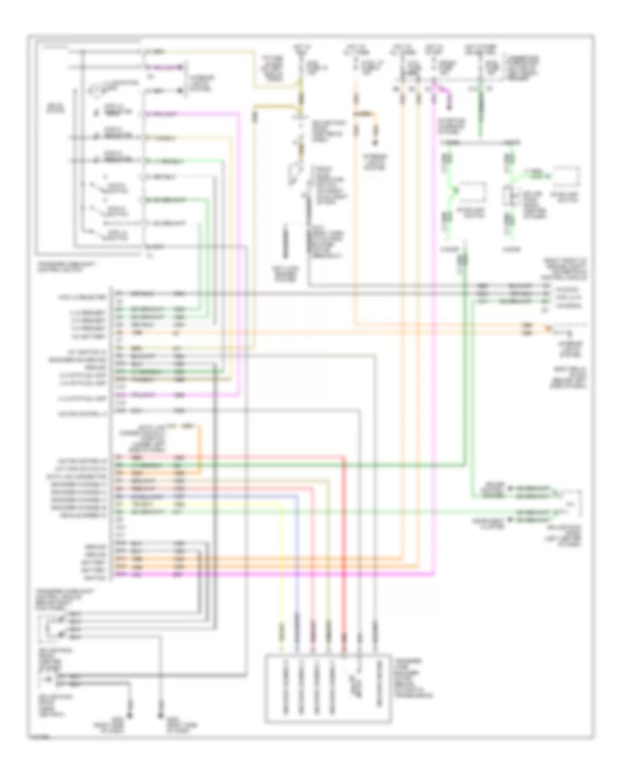 https://portal-diagnostov.com/license.html
Automotive Electricians Portal FZCO
Automotive Electricians Portal FZCO
https://portal-diagnostov.com/license.html
https://portal-diagnostov.com/license.html
Automotive Electricians Portal FZCO
Automotive Electricians Portal FZCOList of elements for Transfer Case Wiring Diagram, with 2-Speed Selectable Transfer Case for GMC Sonoma 2004:
- (a/t) pnp switch in
- (right front of engine compt) powertrain control module
- 12v battery
- 12v ignition (3)
- 2 door
- 2 hi request
- 2 hi status lamp
- 2wd hi indicator
- 2wd hi switch
- 4 door
- 4 hi request
- 4 hi status lamp
- 4 lo request
- 4 lo status lamp
- 4wd fuse 15 10a
- 4wd hi indicator
- 4wd hi switch
- 4wd lo in
- 4wd lo indicator
- 4wd lo selected
- 4wd lo switch
- Anti-lock brakes system
- Atc fuse 20a
- Axle sw
- Battery
- Body relay block (behind left side of dash)
- Btsi fuse 10a
- C10
- C11
- C12
- C13
- C14
- C15
- C16
- Crank fuse 10a
- Cruise control system
- Ctsy lp fuse 8 10a
- D10
- D11
- D12
- D13
- D14
- D15
- D16
- Data link connector
- Data link connector (dlc) (partial) (under left side of dash)
- Encoder channel a
- Encoder channel b
- Encoder channel c
- Encoder channel p
- Encoder channel-a
- Encoder channel-b
- Encoder channel-c
- Encoder channel-p
- Encoder ground
- Encoder sig ground
- Front axle indicator switch (on front axle, right of diff)
- G203 (right side of dash)
- G205 (right side of dash)
- Ground
- Hot at all times
- Hot in park or neutral
- Hot in run
- Hot in start
- I/p fuse block (on left end of dash)
- Ignition
- Illumination lamp
- Instrument cluster
- Interior lights system
- M shift motor
- Motor control a
- Motor control b
- Red
- S121 (body harn, 6.5 cm from blower motor breakout)
- S208
- Solid state
- Splice pack sp204 (center of dash)
- Splice pack sp200 (center of dash)
- Splice pack sp200 (left center of dash)
- Splice pack sp203 (near ashtray)
- Splice pack sp204 (center of dash)
- Starting/ charging system
- Stoplamp switch
- Transfer case encoder motor (behind automatic transmission)
- Transfer case shift control module (behind right kick panel)
- Transfer case shift control switch
- Underhood fuse block (on top of left front fender)
- Vehicle speed in
- Vs signal
WARNING SYSTEMS
Warning Systems Wiring Diagram for GMC Sonoma 2004
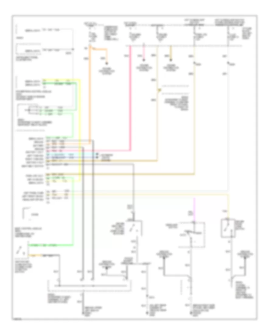 https://portal-diagnostov.com/license.html
Automotive Electricians Portal FZCO
Automotive Electricians Portal FZCO
https://portal-diagnostov.com/license.html
https://portal-diagnostov.com/license.html
Automotive Electricians Portal FZCO
Automotive Electricians Portal FZCOList of elements for Warning Systems Wiring Diagram for GMC Sonoma 2004:
- (behind right side of dash, between c203 & splice packs) g203
- (behind upper left end of dash) g200
- (on left rear corner of vehicle, near c403) g450
- A12
- Auto
- B11
- Battery
- Body control module (bcm) (under dash, on heater case)
- Chime
- Cruise fuse 3 10a
- Driver door jamb switch
- Driver seat belt switch (open when buckled)
- Exterior lights system
- Gauges fuse 4 10a
- Ground
- Ground distribution system
- Head
- Headlamp off sig
- Headlamp switch
- Hot at all times
- Hot in run
- Hot in run & start
- Hot w/headlamp switch in park or head
- Hot w/headlamp switch in park or head position rheostat controlled
- I/p fuse block (on left end of dash)
- Ignition 1 volt
- Ignition 3 volt
- Ignition key alarm switch (closed w/key in ignition switch)
- Illum fuse 12 10a
- Inst panel fuse
- Instrument panel cluster (ipc)
- Key in ign sw
- Left front dr sw
- Left turn sig
- Nca
- Park
- Park lps fuse 5 10a
- Park lps volt
- Pickup except crew cab
- Pnk
- Power distribution system
- Powertrain control module (pcm) (on right side of engine compartment)
- Radio
- Right turn sig
- S205
- S276
- S283
- S313
- Seat belt switch
- Serial data
- Sp200 (strapped to body harness, in center front of dash, to right of sp204)
- Sp201 (strapped to body harness, near body relay block)
- Sp202 (strapped to body harness, at left center of dash)
- Sp203 (in dash harness, in front of ashtray, strapped to body harness)
- Tan
- Tbc fuse 10a
- Underhood fuse block (on top of left front inner wheelwell)
- Utility
WIPER/WASHER
Front Wiper/Washer Wiring Diagram for GMC Sonoma 2004
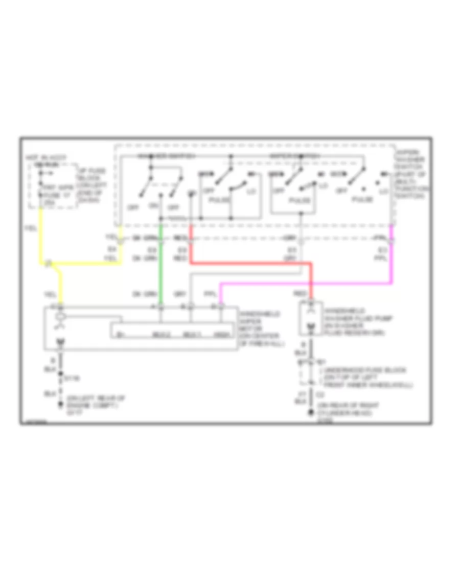 https://portal-diagnostov.com/license.html
Automotive Electricians Portal FZCO
Automotive Electricians Portal FZCO
https://portal-diagnostov.com/license.html
https://portal-diagnostov.com/license.html
Automotive Electricians Portal FZCO
Automotive Electricians Portal FZCOList of elements for Front Wiper/Washer Wiring Diagram for GMC Sonoma 2004:
- (on left rear of engine compt) g117
- (on rear of right cylinder head) g102
- Frt wpr fuse 17 25a
- High
- Hot in accy or run
- I/p fuse block (on left end of dash)
- Mist
- Mux1
- Mux2
- Off
- Pulse
- Red
- S118
- Underhood fuse block (on top of left front inner wheelwell)
- Washer switch
- Windshield washer fluid pump (in washer fluid reservoir)
- Windshield wiper motor (on center of firewall)
- Wiper switch
- Wiper/ washer switch (part of multi- function switch)

 Čeština
 Dansk
Dansk Deutsch
 Ελληνικά
 English
 English
 Español
 Suomi
Suomi Français
 Français
 עברית
עברית Hrvatski
 Magyar
 Italiano
 한국어
한국어 Nederlands
 Polski
 Português
 Português
 Română
 Русский
 Slovenčina
 Slovenščina
 Svenska
 Türkçe
 中文 (中国)
