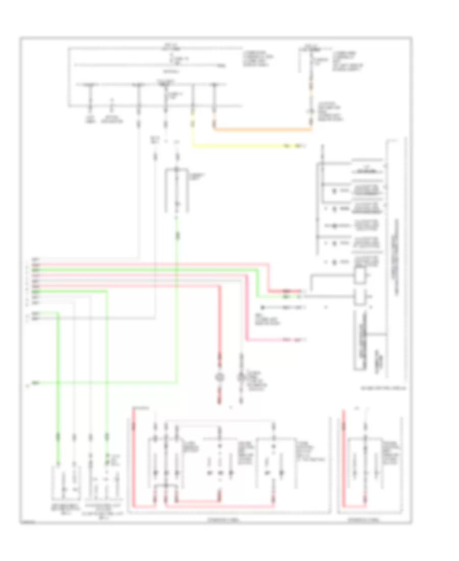
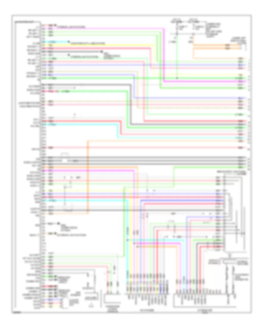
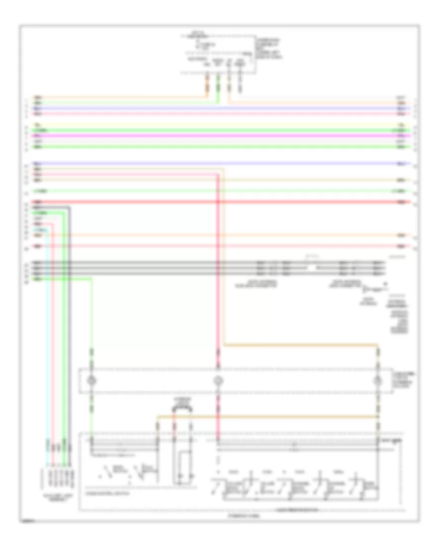
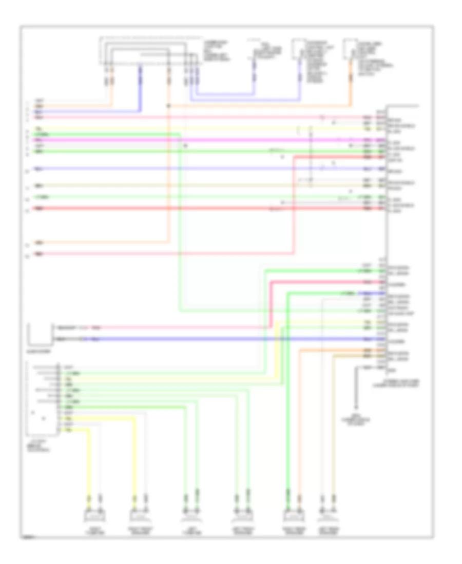
AIR CONDITIONING
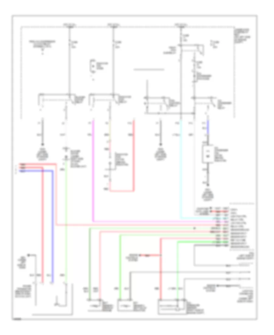
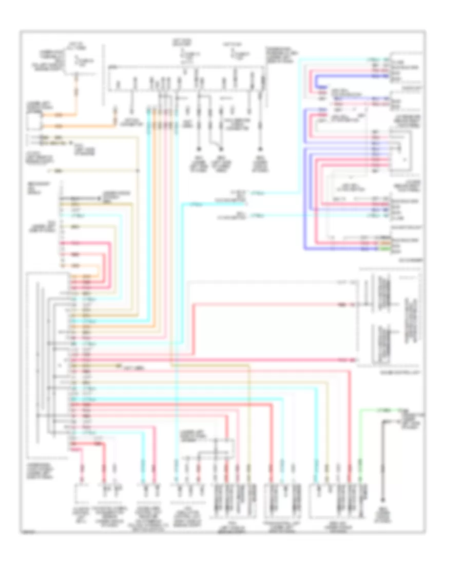
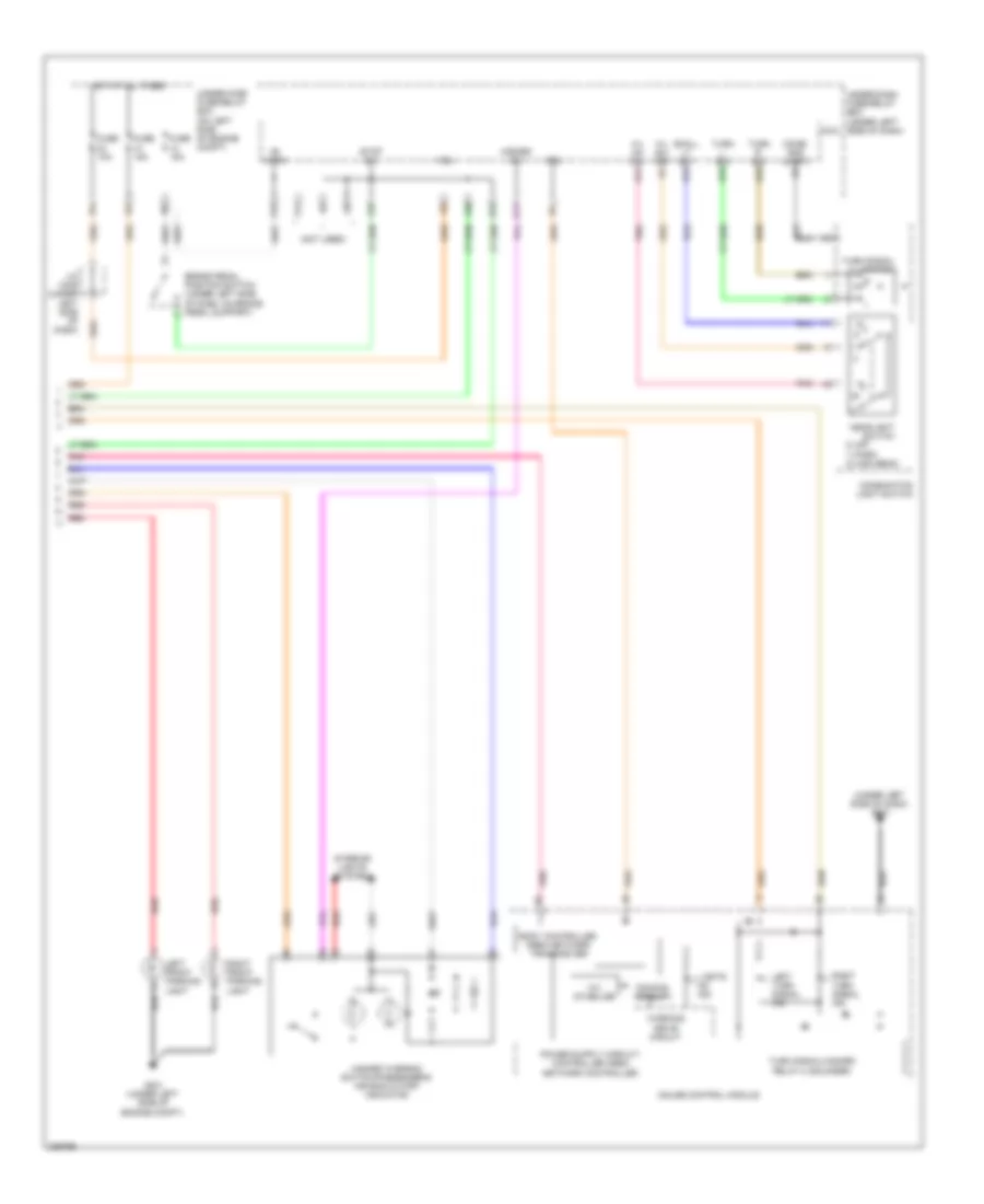
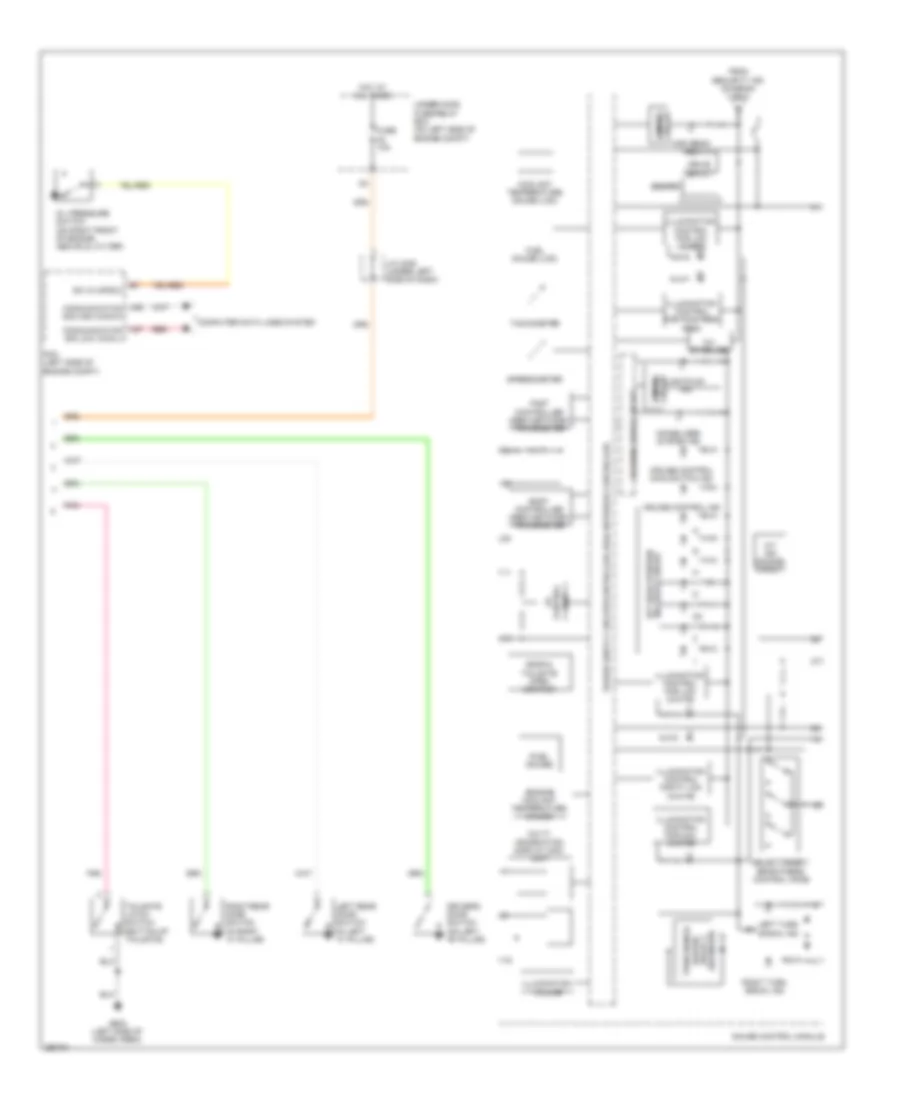
Automatic A/C Wiring Diagram (1 of 2) for Honda CR-V EX 2008
 https://portal-diagnostov.com/license.html
Automotive Electricians Portal FZCO
Automotive Electricians Portal FZCO
https://portal-diagnostov.com/license.html
https://portal-diagnostov.com/license.html
Automotive Electricians Portal FZCO
Automotive Electricians Portal FZCO
List of elements for Automatic A/C Wiring Diagram (1 of 2) for Honda CR-V EX 2008:
- (lower left front of engine) a/c compressor
- (under left side of dash) under-dash junction box
- (under middle of dash) g503
- A/c compressor clutch
- A/c compressor clutch relay
- A12
- A13
- Acs
- Amd- p
- Amd-p
- B-can
- B11
- B12
- B13
- Blower feedback
- Blw-g
- Blw-v
- Climate control unit
- Computer data lines system
- Driver's air mix control motor (under left side of dash, on hvac unit)
- Evaporator temperature sensor (under middle of dash)
- F/r d-p
- F20
- F26
- Front passenger's air mix control motor (under left side of dash, on hvac unit)
- Frs
- Fuse 10a
- Fuse 7.5a
- G12
- Gnd
- Hot at all times
- Hot in on
- Ig2
- Ig2 hav
- Ill-
- In-car temperature sensor (in left side of dash)
- Interior lights
- Junction connector c101 (left rear of engine compt)
- M- cool
- M- def
- M- hot
- M- vent
- M-cool
- M-frs
- M-hot
- M-rec
- M-vent
- Micu
- Mode
- Mode 1
- Mode 2
- Mode 3
- Mode 4
- Mode control motor (behind right side of dash, on hvac unit)
- Mode def
- N11
- Navigation system
- Nca
- Outside air temperature sensor (behind middle of front bumper)
- Pnk
- Rec
- Recirculation control motor (behind right side of dash, on blower unit)
- Red
- Red-p
- S5v
- Sens gnd
- Sens-com
- Small
- Sunlight sensor (top center of dash)
- System
- Tam
- Teva
- Thermal protector
- To blower motor relay (diagram 2 of 2)
- Tsun
- Under-dash fuse/relay box (under left side of dash)
- Under-hood fuse/relay box (on left side of engine compt)
- Usa: ex-l & canada
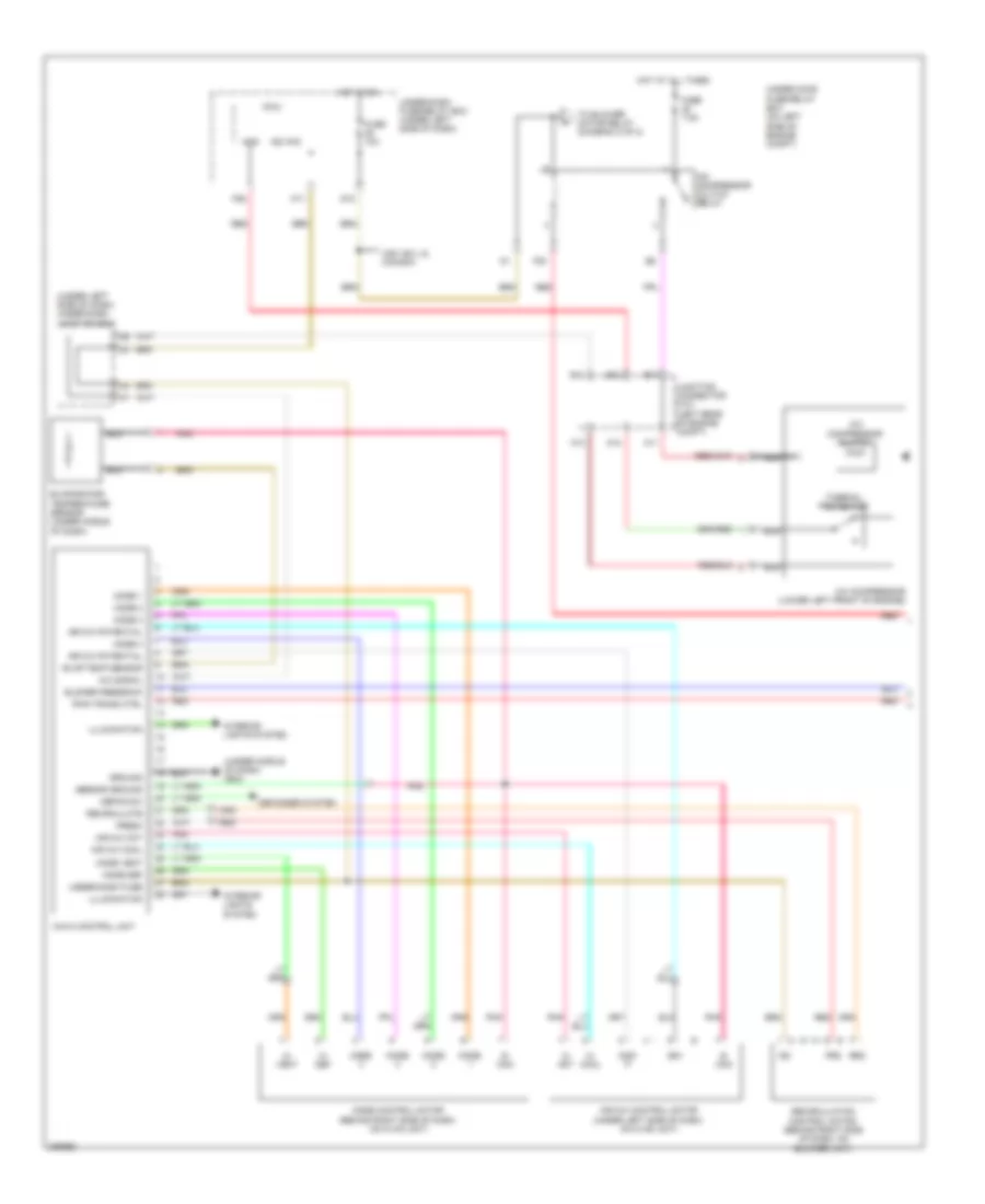
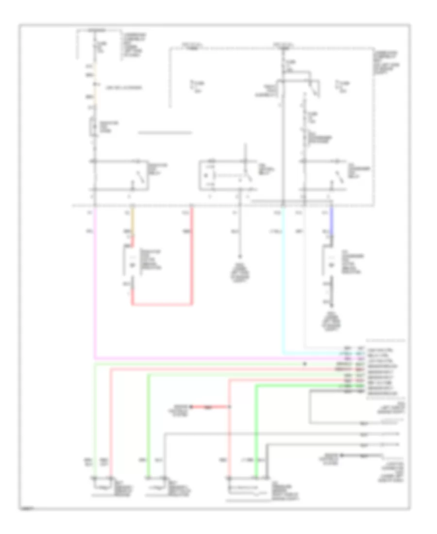
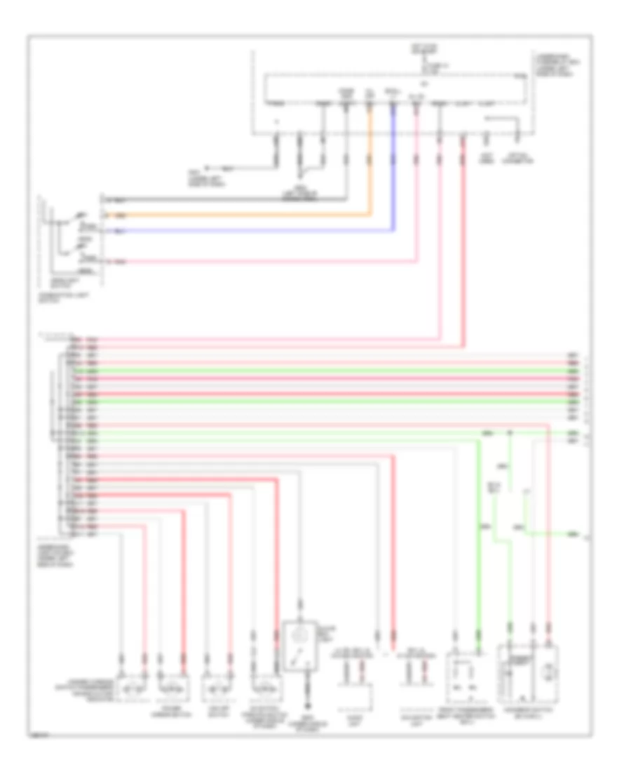
Automatic A/C Wiring Diagram (2 of 2) for Honda CR-V EX 2008
 https://portal-diagnostov.com/license.html
Automotive Electricians Portal FZCO
Automotive Electricians Portal FZCO
https://portal-diagnostov.com/license.html
https://portal-diagnostov.com/license.html
Automotive Electricians Portal FZCO
Automotive Electricians Portal FZCOList of elements for Automatic A/C Wiring Diagram (2 of 2) for Honda CR-V EX 2008:
- A/c condenser fan diode
- A/c condenser fan motor (behind radiator)
- A/c condenser fan relay
- A/c pressure sensor (right side of engine compt)
- A14
- A16
- A19
- A21
- A33
- A36
- A37
- B23
- B33
- Blower motor (under right side of dash, on a/c blower unit)
- Blower motor relay
- Can-h
- Can-l
- Computer data lines system
- Ect sensor 1 (rear of engine)
- Ect sensor 2 (bottom of radiator)
- Engine controls system
- F11
- F12
- F14
- F16
- Fan control relay
- From a/c compressor clutch relay (diagram 1 of 2)
- Fuse 15a
- Fuse 20a
- Fuse 40a
- Fuse 7.5a
- G301 (under left side of engine compt)
- G302 (under left side of engine compt)
- G401 (under left side of dash)
- High fan ctrl
- Hot at all times
- Junction connector c404 (under left side of dash)
- Low fan ctrl
- Nca
- Pcm (left side of engine compt)
- Pgm-fi main sub-relay
- Power transistor (behind right side of dash, on hvac unit)
- Radiator fan diode
- Radiator fan motor (behind radiator)
- Radiator fan relay
- Red
- Ref voltage
- Relay ctrl
- Sensor ground
- Sensor input
- Under-hood fuse/relay box (on left side of engine compt)
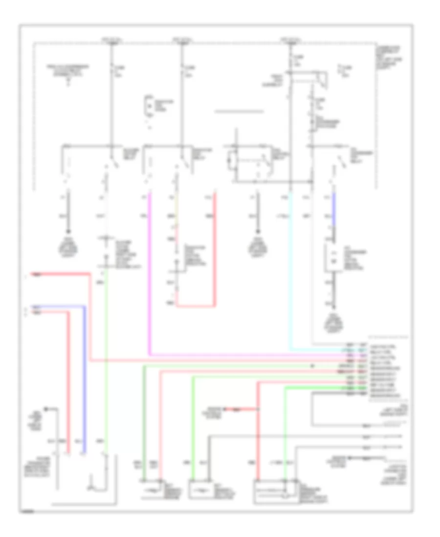
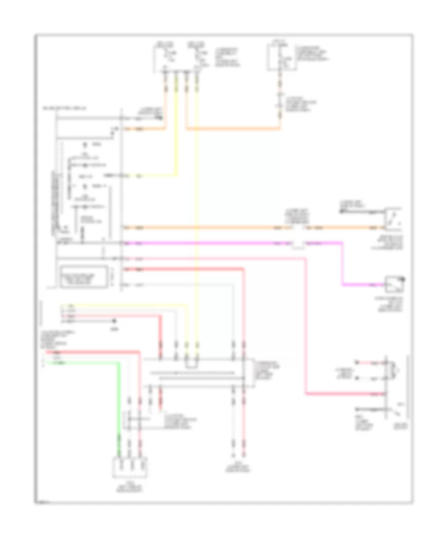
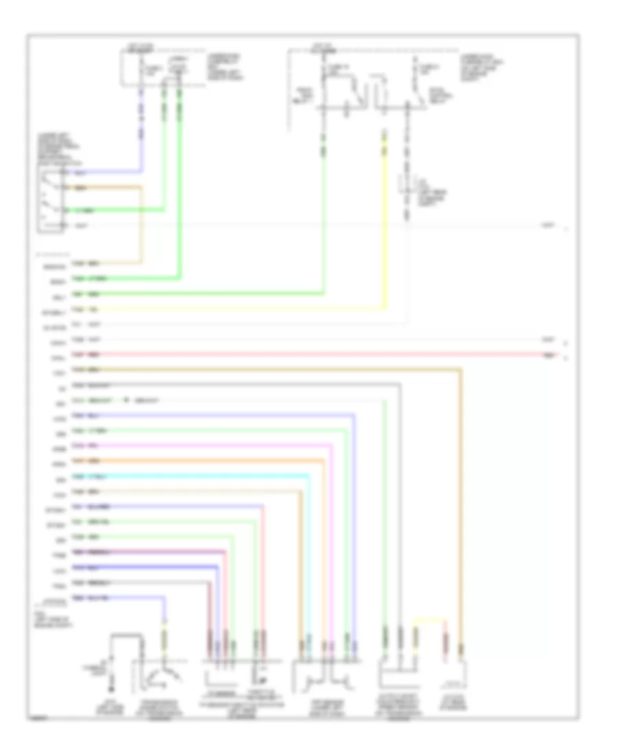
Manual A/C Wiring Diagram (1 of 2) for Honda CR-V EX 2008
 https://portal-diagnostov.com/license.html
Automotive Electricians Portal FZCO
Automotive Electricians Portal FZCO
https://portal-diagnostov.com/license.html
https://portal-diagnostov.com/license.html
Automotive Electricians Portal FZCO
Automotive Electricians Portal FZCOList of elements for Manual A/C Wiring Diagram (1 of 2) for Honda CR-V EX 2008:
- (under left side of dash) under-dash junction box
- (under middle of dash) g503
- A/c compressor (lower left front of engine)
- A/c compressor clutch
- A/c compressor clutch relay
- A/c signal
- A11
- A12
- A13
- Acs
- Air mix control motor (under left side of dash, on hvac unit)
- Air mix cool
- Air mix hot
- Air mix potential
- Amd- p
- B11
- B12
- B13
- Blower feedback
- Defog sw
- Defogger system
- Evap temp sensor
- Evaporator temperature sensor (under middle of dash)
- F20
- F26
- Fresh
- Frs
- Fuse 10a
- Fuse 7.5a
- G12
- Ground
- Havc control unit
- Hot at all times
- Hot in on
- Ig2
- Ig2 hac
- Illumination
- Interior lights system
- Junction connector c101 (left rear of engine compt)
- M- cool
- M- def
- M- hot
- M- vent
- Micu
- Mode
- Mode 1
- Mode 2
- Mode 3
- Mode 4
- Mode control motor (behind right side of dash, on hvac unit)
- Mode def
- Mode vent
- N11
- Nca
- Pnk
- Pwr trans ctrl
- Rec
- Recirculate
- Recirculation control motor (behind right side of dash, on blower unit)
- Red
- S- com
- S5v
- Sensor ground
- Thermal protector
- To blower motor relay (diagram 2 of 2)
- Under-dash fuse
- Under-dash fuse/relay box (under left side of dash)
- Under-hood fuse/relay box (on left side of engine compt)
- Usa: ex-l & canada
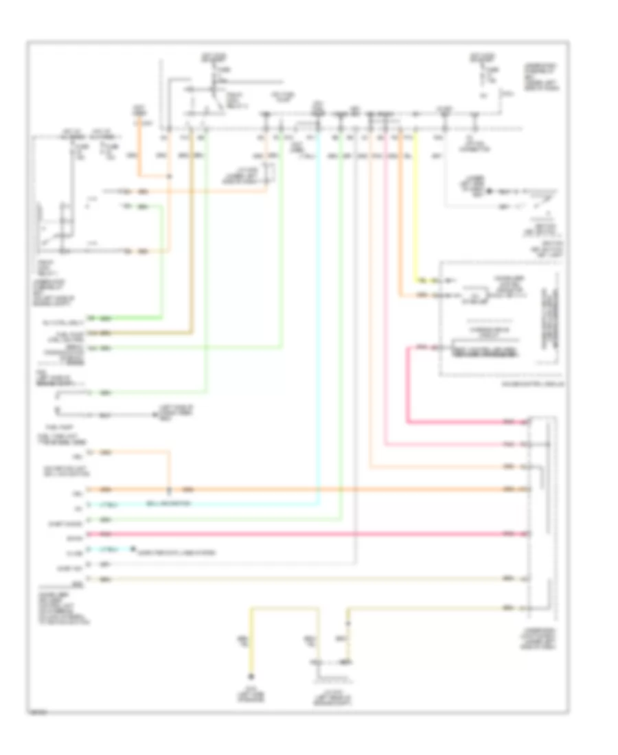
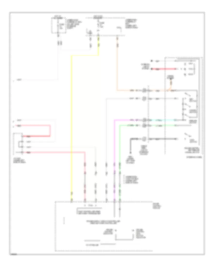
Manual A/C Wiring Diagram (2 of 2) for Honda CR-V EX 2008
 https://portal-diagnostov.com/license.html
Automotive Electricians Portal FZCO
Automotive Electricians Portal FZCO
https://portal-diagnostov.com/license.html
https://portal-diagnostov.com/license.html
Automotive Electricians Portal FZCO
Automotive Electricians Portal FZCOList of elements for Manual A/C Wiring Diagram (2 of 2) for Honda CR-V EX 2008:
- A/c condenser fan diode
- A/c condenser fan motor (behind radiator)
- A/c condenser fan relay
- A/c pressure sensor (right side of engine compt)
- A14
- A16
- A19
- A21
- A33
- B23
- B33
- Blower motor (under right side of dash, on a/c blower unit)
- Blower motor relay
- Ect sensor 1 (rear of engine)
- Ect sensor 2 (bottom of radiator)
- Engine controls system
- F11
- F12
- F14
- F16
- Fan control relay
- From a/c compressor clutch relay (diagram 1 of 2)
- Fuse 15a
- Fuse 20a
- Fuse 40a
- Fuse 7.5a
- G301 (under left side of engine compt)
- G302 (under left side of engine compt)
- G401 (under left side of dash)
- High fan ctrl
- Hot at all times
- Junction connector c404 (under left side of dash)
- Low fan ctrl
- Nca
- Pcm (left side of engine compt)
- Pgm-fi main sub-relay
- Power transistor (behind right side of dash, on hvac unit)
- Radiator fan diode
- Radiator fan motor (behind radiator)
- Radiator fan relay
- Red
- Ref voltage
- Relay ctrl
- Sensor ground
- Sensor input
- Under-hood fuse/relay box (on left side of engine compt)
ANTI-LOCK BRAKES
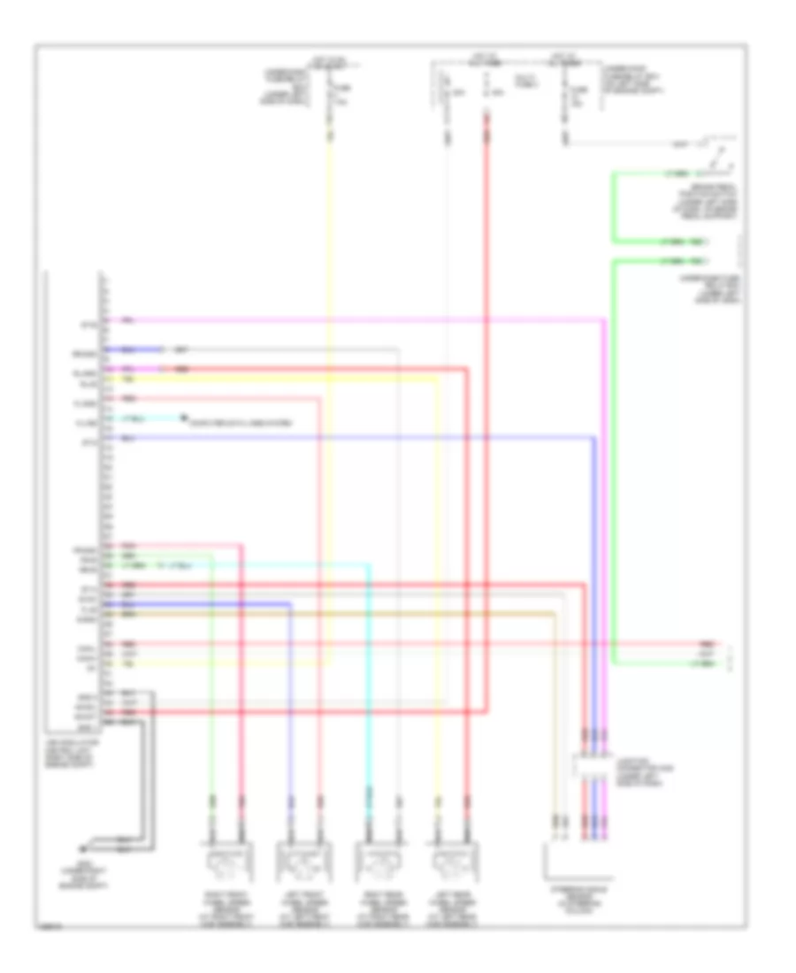
Anti-lock Brakes Wiring Diagram (1 of 2) for Honda CR-V EX 2008
 https://portal-diagnostov.com/license.html
Automotive Electricians Portal FZCO
Automotive Electricians Portal FZCO
https://portal-diagnostov.com/license.html
https://portal-diagnostov.com/license.html
Automotive Electricians Portal FZCO
Automotive Electricians Portal FZCOList of elements for Anti-lock Brakes Wiring Diagram (1 of 2) for Honda CR-V EX 2008:
- +b mot
- +b sol
- 20a
- 40a
- Brake pedal position switch (under left side of dash, on brake pedal support)
- Can-h
- Can-l
- Computer data lines system
- F16
- F25
- F30
- Fl+b
- Fl-gnd
- Fr+b
- Fr-gnd
- Fuse 15a
- Fuse 7.5a
- G202 (under right side of engine compt)
- Gnd 1
- Gnd 2
- Hot at all times
- Hot in on or start
- Ig1
- Junction connector c405 (under left side of dash)
- K-line
- Left front wheel speed sensor (at left front hub assembly)
- Left rear wheel speed sensor (at left rear hub assembly)
- Multi- fuse 3
- Pnk
- Red
- Right front wheel speed sensor (at right front hub assembly)
- Right rear wheel speed sensor (at right rear hub assembly)
- Rl+b
- Rl-gnd
- Rr+b
- Rr-gnd
- S-gnd
- St-a
- St-b
- St-z
- Steering angle sensor (in steering column)
- Svcc
- Under-dash fuse/ relay box (under left side of dash)
- Under-dash fuse/relay box (under left side of dash)
- Under-hood fuse/relay box (on left side of engine compt)
- Vsa modulator control unit (right side of engine compt)
Anti-lock Brakes Wiring Diagram (2 of 2) for Honda CR-V EX 2008
 https://portal-diagnostov.com/license.html
Automotive Electricians Portal FZCO
Automotive Electricians Portal FZCO
https://portal-diagnostov.com/license.html
https://portal-diagnostov.com/license.html
Automotive Electricians Portal FZCO
Automotive Electricians Portal FZCOList of elements for Anti-lock Brakes Wiring Diagram (2 of 2) for Honda CR-V EX 2008:
- (under left side of dash)
- (under left side of dash) g401
- (under left side of dash) g501
- (under left side of dash) under-dash junction box
- A36
- A37
- A40
- Abs ind
- Area network controller
- Brake fluid level switch (on brake fluid reservoir)
- Brake system ind
- Can-h
- Can-l
- Dlc (under left side of dash)
- Fast controller area network transceiver
- Fuse 10a
- Fuse 7.5a
- G10
- G501
- G552
- Gauge control module
- Hot at all times
- Hot in on or start
- Ig1
- Interior lights system
- J12
- J13
- Junction connector c404 (under left side of dash)
- Junction connector c405 (under left side of dash)
- Micu
- P10
- Parking brake switch (under left side of dash)
- Pcm (left side of engine compt)
- Pnk
- R20
- Red
- Sw in
- Under-dash fuse/relay box (under left side of dash)
- Under-dash junction box (under left side of dash)
- Under-hood fuse/relay box (on left side of engine compt)
- Vbu
- Vsa activation ind
- Vsa off switch
- Vsa system ind
- Warning drive circuit
- Yaw rate-lateral acceleration sensor (under middle of dash)
ANTI-THEFT
Forced Entry Wiring Diagram (1 of 2) for Honda CR-V EX 2008
 https://portal-diagnostov.com/license.html
Automotive Electricians Portal FZCO
Automotive Electricians Portal FZCO
https://portal-diagnostov.com/license.html
https://portal-diagnostov.com/license.html
Automotive Electricians Portal FZCO
Automotive Electricians Portal FZCOList of elements for Forced Entry Wiring Diagram (1 of 2) for Honda CR-V EX 2008:
- (not used)
- (not used) c502
- (on transmission housing) transmission range switch
- (under left side of dash) g501
- (under middle of dash) g503
- +b d/l
- Atp-p
- B-can
- Door lock knob
- Dr lk rly
- Driver's door key cylinder switch
- Driver's door lock actuator/knob switch/ key cylinder switch (in driver's door)
- Driver's door lock knob switch
- Drv dr unlk rly
- E13
- E14
- E17
- E19
- E20
- E21
- E31
- E33
- E36
- E37
- Ex & ex-l
- Exterior lights system
- F20
- F23
- F27
- Fr dr sw (as)
- Fr dr sw (dr)
- Front passenger's door lock actuator/knob switch (in front passenger's door)
- Front passenger's door lock knob switch
- Fuse 10a
- Fuse 15a
- Fuse 20a
- Fuse 7.5a
- G101 (left side of engine)
- G13
- G16
- G17
- G401 (under left side of dash)
- G552
- G602 (left side of cargo area)
- Headlights system
- Hood sw
- Horn rly
- Horns system
- Hot at all times
- Hot in on or start
- Ig key sw
- Ig1
- Junction connector c101 (left rear of engine compt)
- Kc dr lock
- Kc dr unlock
- Key
- Lock
- Low beam headlight rly
- M10
- Micu
- N13
- P-gnd
- Pass dr unlk rly
- Pnk
- R16
- Red
- Red b1
- Rem as lock
- Rem as unlock
- Rem dr lock
- Rem dr unlock
- Right rear door lock actuator/knob switch (in right rear door)
- Right rear door lock knob switch
- Rr dr sw (as)
- Rr dr sw (dr)
- S3 (thermal joint)
- Sil as unlock
- Sil dr lock
- Sil dr unlock
- Sil ra unlock
- Sil rd unlock
- T/g handle sw
- T/g sw
- T/g unlk rly
- T22
- T23
- T24
- T25
- T26
- T27
- T28
- T29
- T30
- T31
- T32
- Taillight rly
- Under-dash fuse/relay box (under left side of dash)
- Unlock
- Vbu
Forced Entry Wiring Diagram (2 of 2) for Honda CR-V EX 2008
 https://portal-diagnostov.com/license.html
Automotive Electricians Portal FZCO
Automotive Electricians Portal FZCO
https://portal-diagnostov.com/license.html
https://portal-diagnostov.com/license.html
Automotive Electricians Portal FZCO
Automotive Electricians Portal FZCOList of elements for Forced Entry Wiring Diagram (2 of 2) for Honda CR-V EX 2008:
- (bottom of tailgate) tailgate release actuator
- (in left rear door) left rear door lock actuator/knob switch
- (left side of cargo area) g602
- Audio unit
- B-can
- Blinking circuit
- Body controller area network transceiver
- Driver's door lock switch
- Driver's door switch (on left "b" pillar)
- Ex & ex-l w/o navigation
- Ex-l w/ navigation
- Front passenger's door lock switch
- Front passenger's door switch (on right "b" pillar)
- Front passenger's window switch
- Fuse 10a
- Fuse 15a
- G301 (under left side of engine compt)
- G501 (under left side of dash)
- G503 (under middle of dash)
- G601 (right side of cargo area)
- G602 (left side of cargo area)
- Gauge control module
- Hood switch (except lx) (front of engine compt)
- Hot at all times
- Ignition key switch
- Ignition key switch/key light
- Immobilizer- keyless control unit (on steering column, integral to ignition switch)
- J/c c405 (under left side of dash)
- Left rear door switch (in left "c" pillar)
- Left unlock
- Lock
- Navigation unit
- Pnk
- Power window master switch/ driver's door lock switch
- Power windows system
- Rear door lock knob switch
- Right rear door switch (in right "c" pillar)
- Scty radio
- Security indicator (except: lx)
- Tailgate latch switch (bottom of tailgate)
- Tailgate outer handle switch
- Under-dash junction box (under left side of dash)
- Under-hood fuse/relay box (on left side of engine compt)
- Unlock
Immobilizer Wiring Diagram for Honda CR-V EX 2008
 https://portal-diagnostov.com/license.html
Automotive Electricians Portal FZCO
Automotive Electricians Portal FZCO
https://portal-diagnostov.com/license.html
https://portal-diagnostov.com/license.html
Automotive Electricians Portal FZCO
Automotive Electricians Portal FZCOList of elements for Immobilizer Wiring Diagram for Honda CR-V EX 2008:
- (ig1) fuel pump
- (left side of cargo area) g602
- (not used)
- (under left side of dash) g501
- 10v stabilize
- A15 fuel pump ctrl (imo fpr)
- B-can
- Body controller area network transceiver
- C401
- Communication (s-net5v) (imocd)
- Computer data lines system
- Ex-l: navigation
- F10
- Fuel pump
- Fuel tank unit (top of fuel tank)
- Fuse 10a
- Fuse 15a
- Fuse 7.5a
- G101 (left side of engine)
- Gauge control module
- Gnd
- Hot at all times
- Hot in on or start
- Ig key sw
- Ig1
- Ignition key switch
- Ignition key switch/ key light
- Ill+
- Immobilizer system indicator
- Immobilizer- keyless control unit (on steering column, integral to ignition switch)
- Imocd
- J/c c101 (left rear of engine compt)
- J/c c405 (under left side of dash)
- K-line
- Key sw
- L10
- Micu
- Navigation unit (ex-l: navigation)
- Option connector
- P10
- Pcm (left side of engine compt)
- Pgm-fi main relay 1
- Pgm-fi main relay 2
- Pnk
- R11
- R12
- R16
- Rly ctrl (mrly)
- S-net (imocd)
- Serial a44
- Under-dash fuse/relay box (under left side of dash)
- Under-dash junction box (under left side of dash)
- Under-hood fuse/relay box (on left side of engine compt)
- Vbu
- Warning drive circuit
BODY CONTROL MODULES
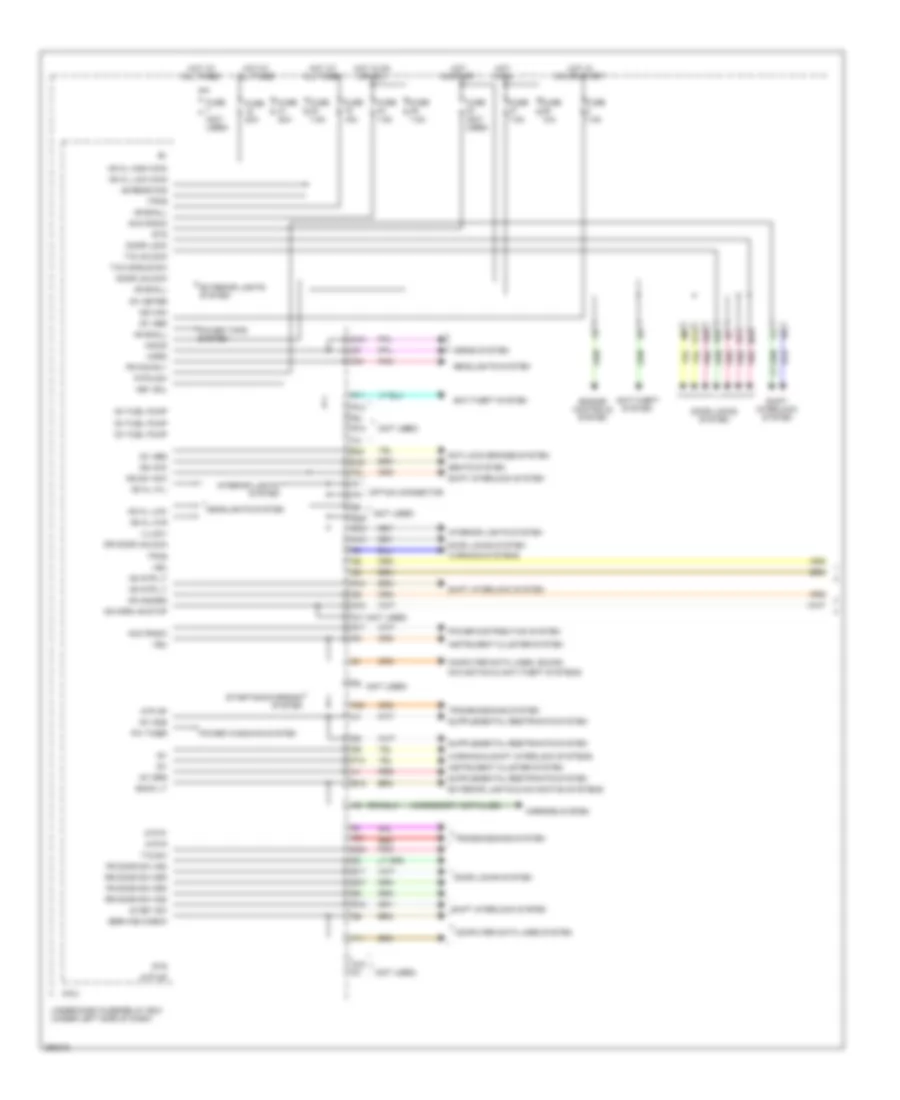
Body Control Modules Wiring Diagram (1 of 2) for Honda CR-V EX 2008
 https://portal-diagnostov.com/license.html
Automotive Electricians Portal FZCO
Automotive Electricians Portal FZCO
https://portal-diagnostov.com/license.html
https://portal-diagnostov.com/license.html
Automotive Electricians Portal FZCO
Automotive Electricians Portal FZCOList of elements for Body Control Modules Wiring Diagram (1 of 2) for Honda CR-V EX 2008:
- (accessory installed)
- (not used)
- +b h/l hi-l
- +b h/l hi-r
- +b h/l high main
- +b h/l low
- +b h/l low main
- +b hazard
- +b horn,+b stop
- +b intr lt
- +b rear fog
- +b small
- Acc radio
- Anti-lock brakes system
- Anti-theft system
- Atp np
- Atp-p
- Back lt
- Computer data lines system
- Computer data lines, sound,
- Door lock
- Door locks system
- Door unlock
- Dr door unlock
- E14
- E15
- E17
- E20
- E21
- E25
- E36
- E37
- Engine controls system
- Exterior lights & navigation systems
- Exterior lights system
- F11
- F21
- F27
- F29
- F31
- Fr door sw (as)
- Fr door sw (dr)
- Fr fog rly
- Fuse (not used)
- Fuse 10a
- Fuse 15a
- Fuse 20a
- Fuse 7.5a
- G15
- G16
- Headlights system
- Horn
- Horns system
- Hot at all times
- Hot in on
- Hot in on or acc
- Hot in on or start
- Hot in start
- Ig key sw
- Ig1
- Ig1 abs
- Ig1 fuel pump
- Ig1 meter
- Ig1 ods
- Ig1 srs
- Ig2 hac
- Illumi+
- Imocd
- Instrument cluster system
- Interior lights system
- Ke sw acc
- Key sol
- M10
- Micu
- Mirrors system
- N13
- Navigation & anti-theft systems
- Option connector
- P-pin sw
- P10
- Pnk
- Power distribution system
- Power tops system
- Power windows system
- Pw timer
- Q12
- Q15
- Q16
- R10
- R11
- R12
- R16
- R17
- R18
- R20
- Red
- Rr door sw (as)
- Rr door sw (dr)
- Seats system
- Service check
- Shift interlock system
- Starting/charging system
- Sts
- T/g handle sw
- T/g sw
- T/g unlock
- Tpms
- Transmissions system
- Under-dash fuse/relay box (under left side of dash)
- Vbu
- Warning & shift interlock systems
- Warning systems
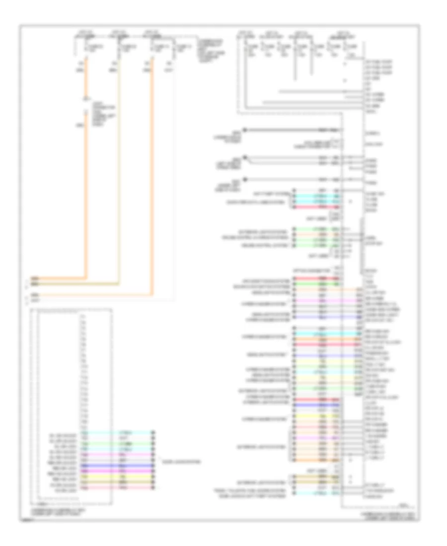
Body Control Modules Wiring Diagram (2 of 2) for Honda CR-V EX 2008
 https://portal-diagnostov.com/license.html
Automotive Electricians Portal FZCO
Automotive Electricians Portal FZCO
https://portal-diagnostov.com/license.html
https://portal-diagnostov.com/license.html
Automotive Electricians Portal FZCO
Automotive Electricians Portal FZCOList of elements for Body Control Modules Wiring Diagram (2 of 2) for Honda CR-V EX 2008:
- (not used)
- + b hazard
- +b d/l
- Acs
- Air conditioning system
- Anti-theft system
- Atp-p
- B-can
- Combi gnd (light)
- Combi gnd (wiper)
- Computer data lines system
- Cruise control & horns systems
- Cruise control system
- Dim sw
- Door locks & anti-theft systems
- Door locks system
- E13
- E26
- E33
- E34
- E39
- E40
- Exterior lights system
- F14
- F18
- F19
- F20
- F25
- F26
- F28
- F30
- F32
- F33
- F34
- Fog lt sw
- Fr wash sw
- Fr washer
- Fr wip as
- Fr wip hi
- Fr wip hi & lo sw
- Fr wip int & lo sw
- Fr wip int vr +
- Fr wip lo
- Fr wip mist sw
- Fuse 10 15a
- Fuse 10a
- Fuse 12 15a
- Fuse 15a
- Fuse 20a
- Fuse 22 7.5a
- Fuse 23 10a
- Fuse 30a
- Fuse 7.5a
- G13
- G401 (under left side of dash)
- G502 (under middle of dash)
- G602 (left side of cargo area)
- H/l off sw
- H/l on sw
- Haz sw
- Headlights system
- Hood sw
- Horn
- Hot at all times
- Hot in on or start
- Ig key sw
- Ig1
- Ig1 fuel pump
- Ig1 ods
- Ig1 srs
- Ig1 wiper
- Illu
- Illum-
- Interior lights system
- Joint connector c405 (under left side of dash)
- K-line
- Kc dr lock
- Kc dr unlock
- L turn lt
- Micu
- Micu chk
- Micu service check connector
- Option connector
- P-gnd
- Passing sw
- Pnk
- Q11
- Q13
- R turn lt
- Red
- Rem as lock
- Rem as unlock
- Rem dr lock
- Rem dr unlock
- Rr wash sw
- Rr washer
- Rr wipe sw
- Rr wiper
- Rr wiper rly cl
- S gnd 2
- S-gnd
- S10
- S11
- S12
- S13
- S14
- S15
- S16
- S17
- S18
- S19
- S20
- Sil as unlock
- Sil dr lock
- Sil dr unlock
- Sil ra unlock
- Sil rd unlock
- Small lt sw
- Sound & navigation systems
- Stop sw
- T/g handle sw
- T10
- T11
- T12
- T13
- T14
- T15
- T16
- T17
- T18
- T19
- T20
- T21
- T22
- T23
- T24
- T25
- T26
- T27
- T28
- T29
- T30
- T31
- T32
- T34
- Trunk, tailgate, fuel doors system
- Turn l sw
- Turn r sw
- Under-dash fuse/relay box (under left side of dash)
- Under-hood fuse/relay box (on left side of engine compt)
- Wiper/washer system
COMPUTER DATA LINES
Computer Data Lines Wiring Diagram for Honda CR-V EX 2008
 https://portal-diagnostov.com/license.html
Automotive Electricians Portal FZCO
Automotive Electricians Portal FZCO
https://portal-diagnostov.com/license.html
https://portal-diagnostov.com/license.html
Automotive Electricians Portal FZCO
Automotive Electricians Portal FZCOList of elements for Computer Data Lines Wiring Diagram for Honda CR-V EX 2008:
- (not used)
- (under left side of dash) j/c c404
- (under left side of dash) j/c c405
- (under middle of dash) g502
- A10 bus-
- A11 communication
- A12 communication
- A24
- A31 service check
- A36 communication sig hi (can-h)
- A37 communication sig lo (can-l)
- A42 write enable sig (wen)
- A5 mes connector
- A6 k-line
- A9 bus+
- Audio unit
- B-can
- Body controller area network transceiver
- Can-h
- Can-l
- Cd changer
- Climate control unit (ex-l)
- Communication
- D3 bus shld gnd
- Dlc (under left side of dash)
- E10 bus-
- E17
- E18
- E3 bus shld gnd
- E33
- E9 bus+
- Ex-l w/ navigation
- F-can hi
- F-can lo
- F11
- F14
- F20
- F28
- Fuse 10 7.5a
- Fuse 23 10a
- Fuse 37 7.5a
- G101 (left side of engine)
- G401 (under left side of dash)
- G502 (under middle of dash)
- G505 (under middle of dash)
- G602 (left side of cargo area)
- Gauge control unit
- H10
- Hot at all times
- Hot in on
- Hot in on or start
- Ig1
- Ig1 meter
- Immobilizer control unit receiver (on steering column, integral to ignition switch)
- In (mes)
- J/c c101 (left rear of engine compt)
- J/c c509 (behind right kick panel)
- J12
- J13
- K-line
- K12
- Lx, ex & ex-l w/o navigation
- Mes connector (under left side of dash)
- Micu
- Micu chk
- Micu service check connector
- Navigation unit
- Option connector
- P-gnd
- Pcm (left side of engine compt)
- Pnk
- Red
- S-gnd
- S-gnd2
- Scs
- Secondary ho2 shield
- Sig (scs)
- Sig hi (can-h)
- Sig lo (can-l)
- Srs unit (under middle of dash)
- T34
- Tpms control unit (under left side of dash)
- Transceiver area network fast controller
- Under-dash fuse/relay box (under left side of dash)
- Under-dash junction box (under left side of dash)
- Under-hood fuse/relay box (on left side of engine compt)
- Usa: ex-l w/ navigation
- Usa: ex-l w/o navigation
- Vbu
- Vsa modulator control unit (right side of engine compt)
- Xm receiver (behind right kick panel)
- Yaw rate-lateral acceleration sensor (under middle of dash)
COOLING FAN
Cooling Fan Wiring Diagram for Honda CR-V EX 2008
 https://portal-diagnostov.com/license.html
Automotive Electricians Portal FZCO
Automotive Electricians Portal FZCO
https://portal-diagnostov.com/license.html
https://portal-diagnostov.com/license.html
Automotive Electricians Portal FZCO
Automotive Electricians Portal FZCOList of elements for Cooling Fan Wiring Diagram for Honda CR-V EX 2008:
- A/c condenser fan diode
- A/c condenser fan motor (behind radiator)
- A/c condenser fan relay
- A/c pressure sensor (right side of engine compt)
- A16
- A19
- A21
- A33
- B23
- B33
- Ect sensor 1 (rear of engine)
- Ect sensor 2 (bottom of radiator)
- Engine controls system
- F11
- F12
- F14
- F16
- Fan control relay
- Fuse 10a
- Fuse 15a
- Fuse 20a
- Fuse 7.5a
- G12
- G301 (under left side of engine compt)
- G302 (under left side of engine compt)
- High fan ctrl
- Hot at all times
- Hot in on
- Junction connector c404 (under left side of dash)
- Low fan ctrl
- Nca
- Pcm (left side of engine compt)
- Pgm-fi main sub-relay
- Radiator fan diode
- Radiator fan motor (behind radiator)
- Radiator fan relay
- Red
- Ref voltage
- Relay ctrl
- Sensor ground
- Sensor input
- Under-dash fuse/relay box (under left side of dash)
- Under-hood fuse/relay box (on left side of engine compt)
- Usa: ex-l & canada
CRUISE CONTROL
Cruise Control Wiring Diagram (1 of 2) for Honda CR-V EX 2008
 https://portal-diagnostov.com/license.html
Automotive Electricians Portal FZCO
Automotive Electricians Portal FZCO
https://portal-diagnostov.com/license.html
https://portal-diagnostov.com/license.html
Automotive Electricians Portal FZCO
Automotive Electricians Portal FZCOList of elements for Cruise Control Wiring Diagram (1 of 2) for Honda CR-V EX 2008:
- (under left side of dash, on brake pedal support) brake pedal position switch
- A15
- A17
- A18
- A20
- A21
- A24
- A25
- A34
- A35
- A36
- A37
- A39
- A40
- App sensor (under left side of dash)
- Apsa
- Apsb
- Atp-fwd
- B18
- B28
- Bksw
- Bkswnc
- C12
- C14
- C20
- C21
- C39
- C43
- Can-h
- Can-l
- Etcs control relay
- Etcsm+
- Etcsm-
- Etcsrly
- F25
- F30
- Fuse 19 15a
- Fuse 21 15a
- Fuse 3 10a
- G101 (left side of engine)
- Hot at all times
- Hot in on or start
- Ig1 etcs
- J/c c101 (left rear of engine compt)
- J/c c103 (at rear of engine)
- Micu
- Mrly
- Output shaft (countershaft) speed sensor (on transmission housing)
- Pcm (left side of engine compt)
- Pgm-fi main relay 1
- Red
- S3 (thermal joint)
- Sg1
- Sg3
- Sg4
- Sg5
- Stop sw
- Throttle actuator
- Tp sensor
- Tp sensor/throttle actuator (left rear of engine)
- Tpsa
- Tpsb
- Transmission range switch (on transmission housing)
- Under-dash fuse/relay box (under left side of dash)
- Under-hood fuse/relay box (on left side of engine compt)
- Vcc1
- Vcc3
- Vcc4
- Vcc5
Cruise Control Wiring Diagram (2 of 2) for Honda CR-V EX 2008
 https://portal-diagnostov.com/license.html
Automotive Electricians Portal FZCO
Automotive Electricians Portal FZCO
https://portal-diagnostov.com/license.html
https://portal-diagnostov.com/license.html
Automotive Electricians Portal FZCO
Automotive Electricians Portal FZCOList of elements for Cruise Control Wiring Diagram (2 of 2) for Honda CR-V EX 2008:
- +b horn
- 10v stabilize
- C11
- Cable reel (top of steering column)
- Cancel switch
- Cruise control indicator
- Cruise control main switch indicator
- Cruise control set/resume cancel switch
- Fast controller area network transceiver
- Fuse 15a
- Fuse 7.5a
- G16
- G501 (under left side of dash)
- Gauge control module
- Horns system
- Hot at all times
- Hot in on or start
- Ig1
- Interior lights system
- J/c c404 (under left side of dash)
- J12
- J13
- J15
- J17
- K14
- Main switch
- Micu
- P10
- Red
- Resume switch
- Set switch
- Steering wheel
- Under-dash fuse/relay box (under left side of dash)
- Under-dash junction box (under left side of dash)
- Under-hood fuse/relay box (on left side of engine compt)
DEFOGGERS
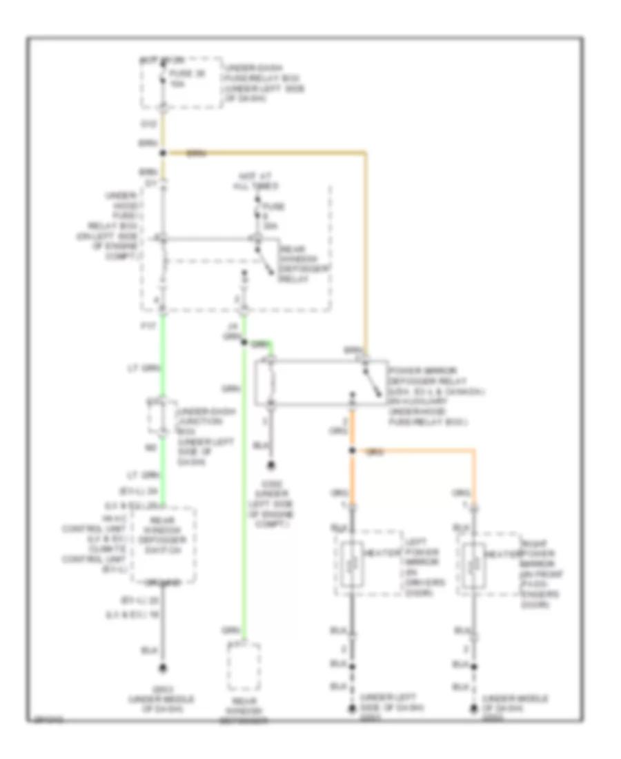
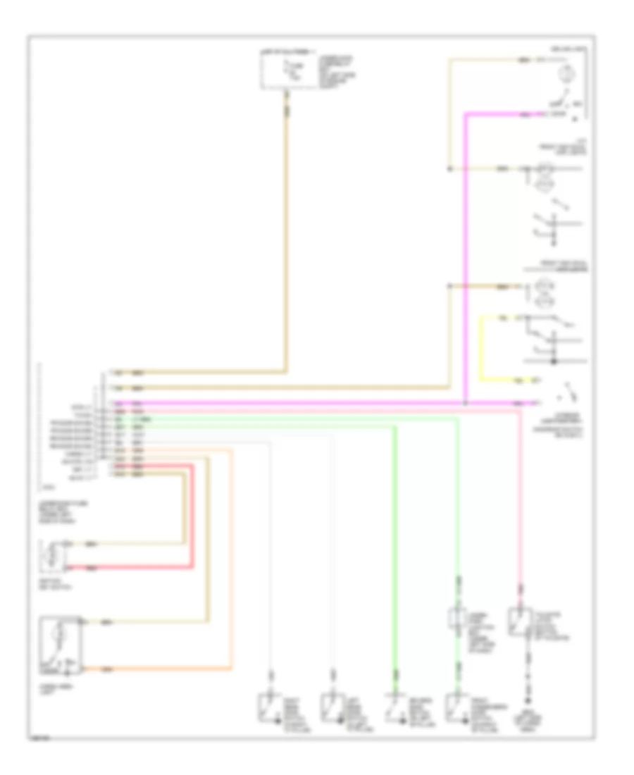
Heated Mirrors Wiring Diagram for Honda CR-V EX 2008
 https://portal-diagnostov.com/license.html
Automotive Electricians Portal FZCO
Automotive Electricians Portal FZCO
https://portal-diagnostov.com/license.html
https://portal-diagnostov.com/license.html
Automotive Electricians Portal FZCO
Automotive Electricians Portal FZCOList of elements for Heated Mirrors Wiring Diagram for Honda CR-V EX 2008:
- (ex-l)
- (lx & ex)
- (under left side of dash) g501
- (under middle of dash) g503
- F17
- Fuse 30a
- Fuse 36 10a
- G12
- G302 (under left side of engine compt)
- G503 (under middle of dash)
- Ground
- Heater
- Hot at all times
- Hot in on
- Hvac control unit (lx & ex) climate control unit (ex-l)
- Left power mirror (in driver's door)
- Power mirror defogger relay (usa: ex-l & canada) (in auxiliary under-hood fuse/relay box)
- Rear window defogger
- Rear window defogger relay
- Rear window defogger switch
- Right power mirror (in front pass- enger's door)
- Under- hood fuse/ relay box (on left side of engine compt)
- Under-dash fuse/relay box (under left side of dash)
- Under-dash junction box (under left side of dash)
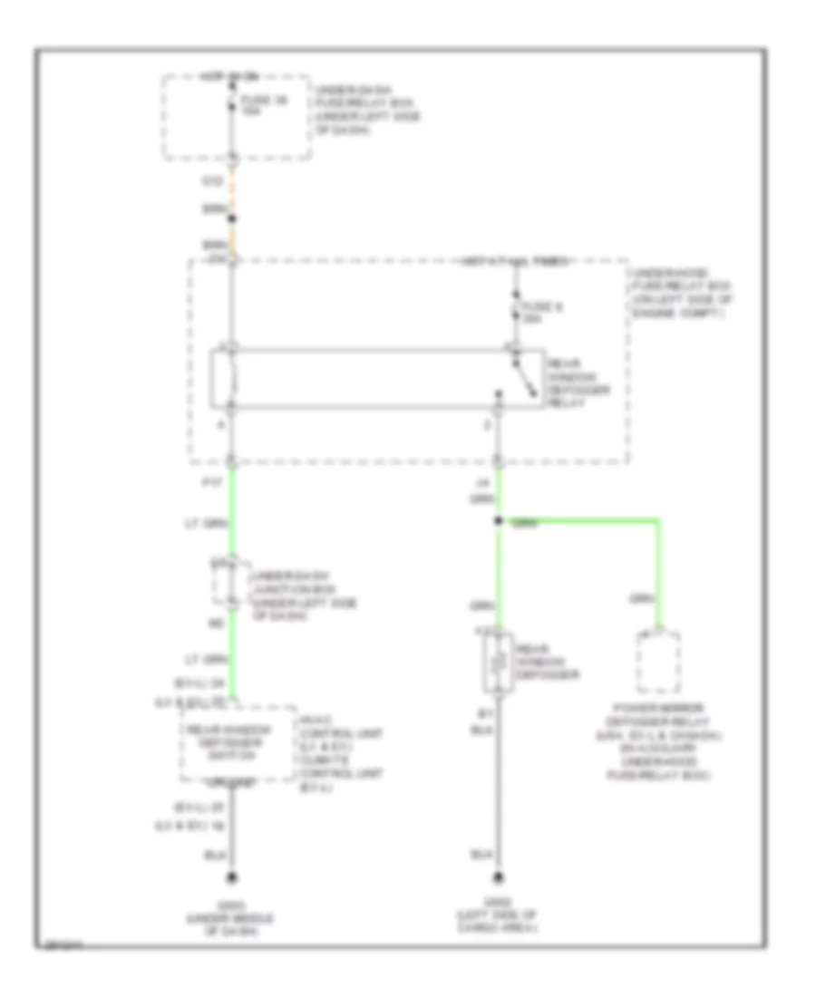
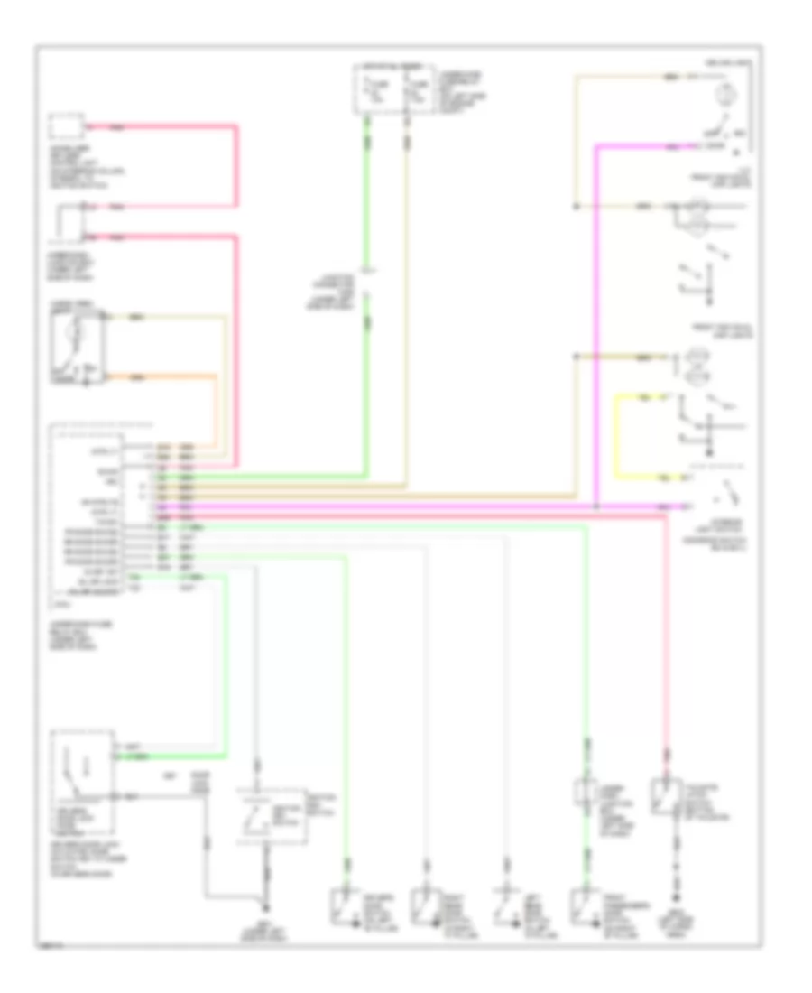
Rear Defogger Wiring Diagram for Honda CR-V EX 2008
 https://portal-diagnostov.com/license.html
Automotive Electricians Portal FZCO
Automotive Electricians Portal FZCO
https://portal-diagnostov.com/license.html
https://portal-diagnostov.com/license.html
Automotive Electricians Portal FZCO
Automotive Electricians Portal FZCOList of elements for Rear Defogger Wiring Diagram for Honda CR-V EX 2008:
- (ex-l)
- (lx & ex)
- F17
- Fuse 36 10a
- Fuse 8 30a
- G12
- G503 (under middle of dash)
- G602 (left side of cargo area)
- Ground
- Hot at all times
- Hot in on
- Hvac control unit (lx & ex) climate control unit (ex-l)
- Power mirror defogger relay (usa: ex-l & canada) (in auxiliary under-hood fuse/relay box)
- Rear window defogger
- Rear window defogger relay
- Rear window defogger switch
- Under-dash fuse/relay box (under left side of dash)
- Under-dash junction box (under left side of dash)
- Under-hood fuse/relay box (on left side of engine compt)
ENGINE PERFORMANCE
2.4L
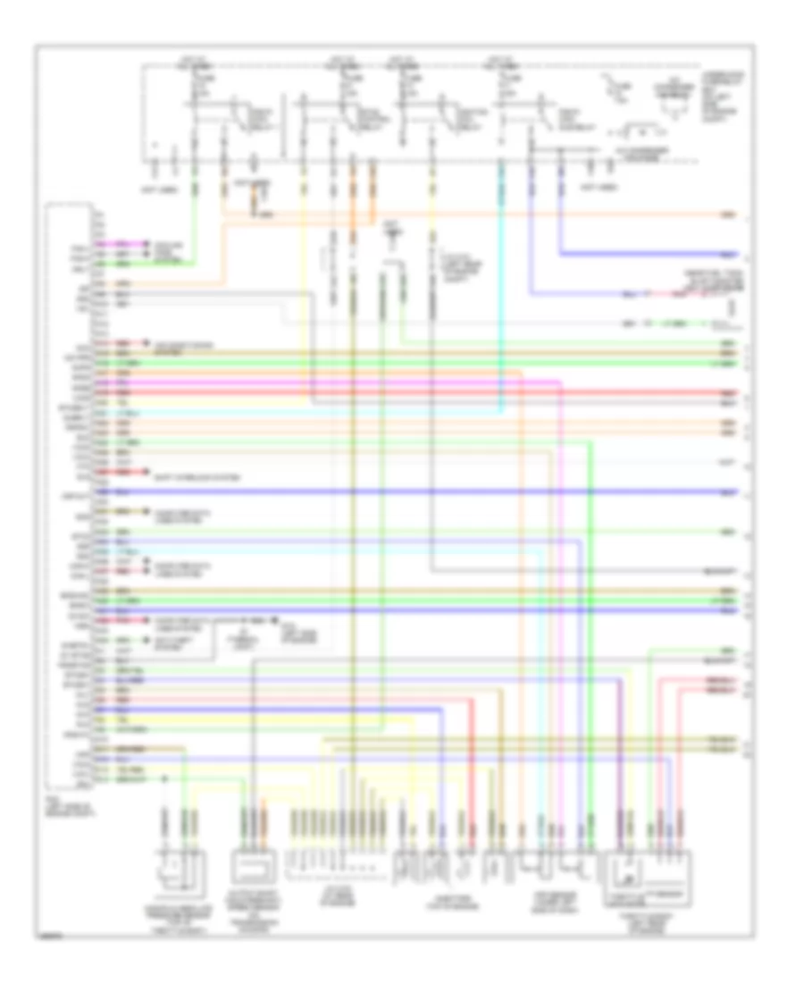
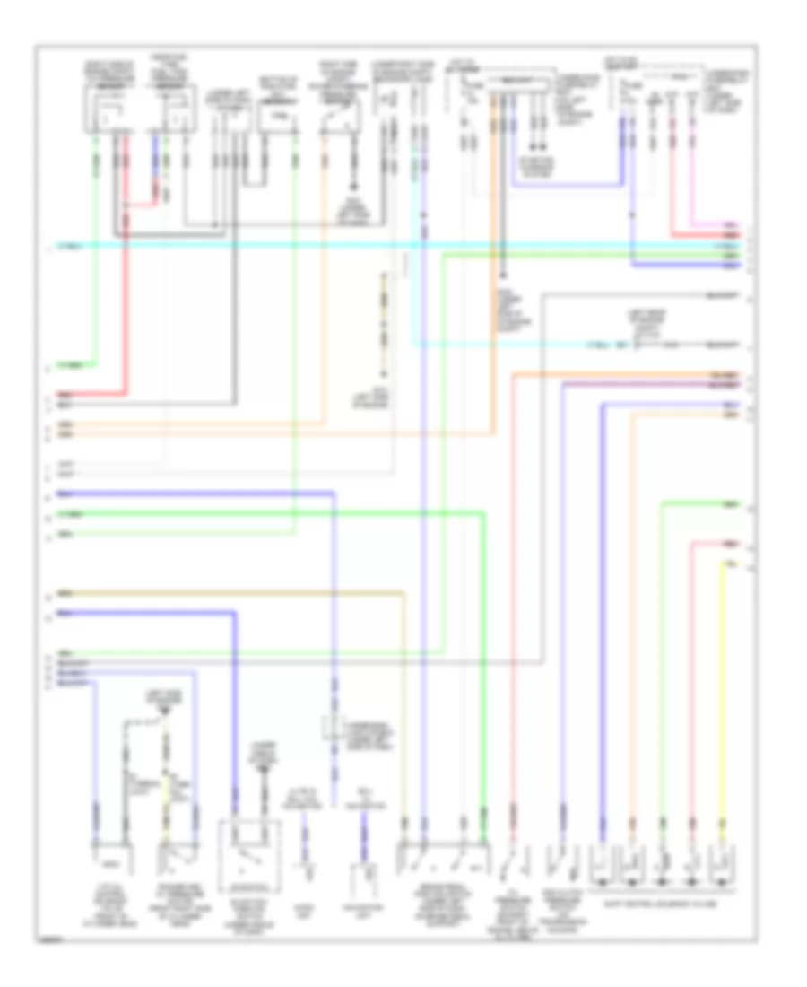
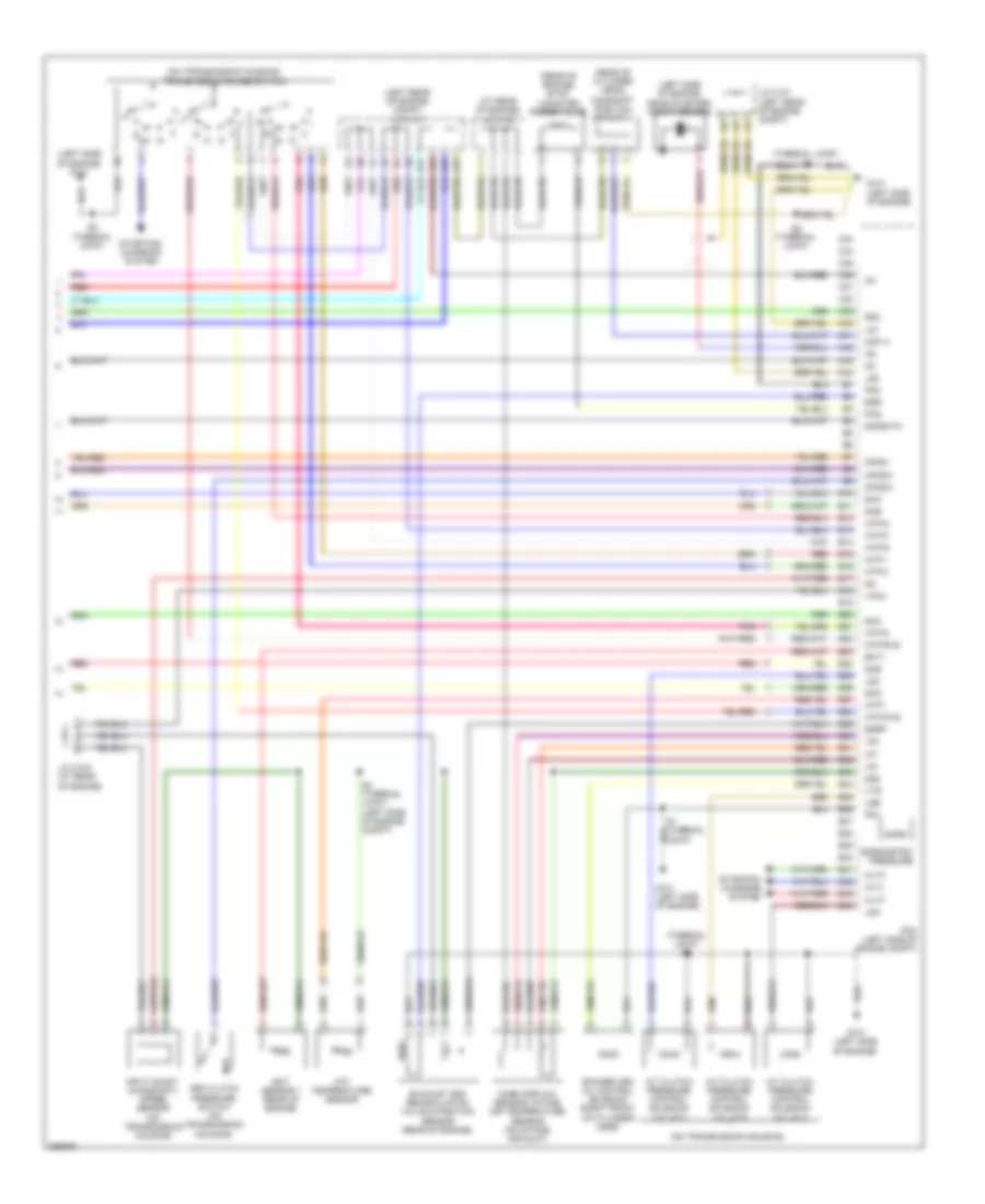
2.4L, Engine Performance Wiring Diagram (1 of 4) for Honda CR-V EX 2008
 https://portal-diagnostov.com/license.html
Automotive Electricians Portal FZCO
Automotive Electricians Portal FZCO
https://portal-diagnostov.com/license.html
https://portal-diagnostov.com/license.html
Automotive Electricians Portal FZCO
Automotive Electricians Portal FZCOList of elements for 2.4L, Engine Performance Wiring Diagram (1 of 4) for Honda CR-V EX 2008:
- (near fuel tank) evap canister vent shut valve
- (not used)
- A/c condenser fan diode
- A/c condenser fan relay
- A10
- A11
- A12
- A13
- A14
- A15
- A16
- A17
- A18
- A19
- A20
- A21
- A22
- A23
- A24
- A25
- A26
- A27
- A28
- A29
- A30
- A31
- A32
- A33
- A34
- A35
- A36
- A37
- A38
- A39
- A40
- A41
- A42
- A43
- A44
- Acc
- Acpd
- Afshtc
- Air conditioning system
- Anti-theft system
- App sensor (under left side of dash)
- Apsa
- Apsb
- B15
- B18
- B20
- B23
- Bksw
- Bkswnc
- C10
- C11
- C12
- C13
- C14
- C401
- Can-h
- Can-l
- Computer data lines system
- Cooling fans system
- D3 sw
- Eld
- Etc2
- Etcs control relay
- Etcsm+
- Etcsm-
- Etcsrly
- F10
- F13
- F16
- F18
- F19
- Fan-h
- Fan-l
- Ftp
- Fuse 15a
- Fuse 7.5a
- G101 (left side of engine)
- Hot at all times
- Ig1 etcs
- Ignition coil relay
- Igp
- Imo fpr
- Inj1
- Inj2
- Inj3
- Inj4
- Injectors (top of engine)
- J/c c101 (left rear of engine compt)
- J/c c103 (at rear of engine)
- Manifold absolute pressure sensor (top of throttle body)
- Map
- Mrly
- Output shaft (countershaft) speed sensor (on transmission housing)
- Pcm (left side of engine compt)
- Pgm-fi main relay 1
- Pgm-fi main sub relay
- Pgmetcs
- Pnk
- Pspsw
- Red
- S-net5v
- S1 (thermal joint)
- Scs
- Sg1
- Sg3
- Sg4
- Sg5
- Shift interlock system
- Sls
- Subrly
- Throttle actuator
- Throttle body (left rear of engine)
- Tp sensor
- Under-hood fuse/relay box (on left side of engine compt)
- Vcc1
- Vcc3
- Vcc4
- Vcc5
- Vcc6
- Vsp-out
- Vsv
- Wen
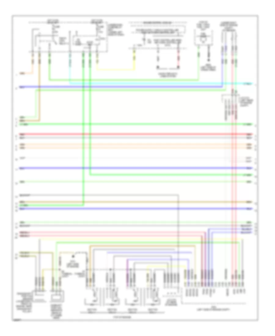
2.4L, Engine Performance Wiring Diagram (2 of 4) for Honda CR-V EX 2008
 https://portal-diagnostov.com/license.html
Automotive Electricians Portal FZCO
Automotive Electricians Portal FZCO
https://portal-diagnostov.com/license.html
https://portal-diagnostov.com/license.html
Automotive Electricians Portal FZCO
Automotive Electricians Portal FZCOList of elements for 2.4L, Engine Performance Wiring Diagram (2 of 4) for Honda CR-V EX 2008:
- (top of engine)
- (top of fuel tank) fuel tank unit
- (under right side of engine compt) a/f sensor
- A14
- A15
- A23
- Afs+
- Afs-
- B10
- B16
- C15
- C16
- C17
- C18
- C19
- C20
- C21
- C22
- C23
- C24
- C25
- C26
- C27
- C28
- C29
- C30
- C31
- C32
- Camshaft position sensor b (rear of cylinder head)
- Ckp
- Cmp
- Computer data lines system
- Crankshaft position sensor (lower right front of engine, near crankshaft pulley)
- F10
- F24
- F25
- F30
- Fast controller area network controller
- Fuel pump
- Fuse 15a
- Fuse 7.5a
- G101 (left side of engine)
- G602 (left side of cargo area)
- Gauge control module
- Hot in on or start
- Icm
- Ig1
- Ig1 fuel pump
- Ignition coil 1
- Ignition coil 2
- Ignition coil 3
- Ignition coil 4
- Igpls1
- Igpls2
- Igpls3
- Igpls4
- J/c c101 (left rear of engine compt)
- J/c c103 (at rear of engine)
- Micu
- Mil ind
- P10
- Pcm (left side of engine compt)
- Pgm-fi main relay 2
- Red
- S1 (thermal joint)
- S2 (thermal joint)
- Sho2s
- Stop sw
- Tpsa
- Tpsb
- Under-dash fuse/relay box (under left side of dash)
- Vtc
- Vtpsw
2.4L, Engine Performance Wiring Diagram (3 of 4) for Honda CR-V EX 2008
 https://portal-diagnostov.com/license.html
Automotive Electricians Portal FZCO
Automotive Electricians Portal FZCO
https://portal-diagnostov.com/license.html
https://portal-diagnostov.com/license.html
Automotive Electricians Portal FZCO
Automotive Electricians Portal FZCOList of elements for 2.4L, Engine Performance Wiring Diagram (3 of 4) for Honda CR-V EX 2008:
- (bottom of radiator) ect sensor 2
- (left rear of engine compt) j/c c101
- (left side of engine) g101
- (near fuel tank) fuel tank pressure sensor
- (right side of engine compt) a/c pressure sensor
- (right side of engine compt) power steering pressure switch
- (under left side of dash) j/c c404
- (under middle of dash) g503
- (under right side of engine compt) secondary ho2s
- +b horn
- 2nd clutch pressure switch (on transmission housing)
- A13
- A18
- Atp -p
- Atp -r
- Audio unit
- B21
- Brake pedal position switch (under left side of dash, on brake pedal support)
- D3 switch
- D3 switch/ park pin switch (under middle of dash)
- Eld unit
- Ex-l w/ navigation
- F15
- F27
- Fuse 10a
- Fuse 15a
- G101 (left side of engine)
- G13
- G16
- G302 (under left side of of engine compt)
- G401 (under left side of dash)
- Hot at all times
- Hot in on or start
- Lx, ex & ex-l w/o navigation
- Micu
- Navigation unit
- Oil pressure switch (on right front of engine, above oil filter)
- Red
- Rocker arm oil pressure switch (front right side of cylinder head)
- S1 (thermal joint)
- S2 (ther- mal joint)
- Shift control solenoid valves
- Starting/ charging system
- Under-dash fuse/relay box (under left side of dash)
- Under-dash junction box (under left side of dash)
- Under-hood fuse/relay box (on left side of engine compt)
- Vsp
- Vtc oil control solenoid valve (front of cylinder head)
2.4L, Engine Performance Wiring Diagram (4 of 4) for Honda CR-V EX 2008
 https://portal-diagnostov.com/license.html
Automotive Electricians Portal FZCO
Automotive Electricians Portal FZCO
https://portal-diagnostov.com/license.html
https://portal-diagnostov.com/license.html
Automotive Electricians Portal FZCO
Automotive Electricians Portal FZCOList of elements for 2.4L, Engine Performance Wiring Diagram (4 of 4) for Honda CR-V EX 2008:
- (at rear of engine) j/c c103
- (left rear of engine compt) j/c c101
- (left side of engine) g101
- (left side of engine, near starter) knock sensor
- (on transmission housing)
- (on transmission housing) transmission range switch
- (rear of cylinder head)
- (rear of engine) evap canister purge valve
- (thermal joint) s3
- 3rd clutch pressure switch (on transmission housing)
- A/t clutch pressure control solenoid valve a
- A/t clutch pressure control solenoid valve b
- A/t clutch pressure control solenoid valve c
- A17
- A22
- Altc
- Altf
- Altl
- Atf temperature sensor
- Atft
- Atp-1
- Atp-2
- Atp-d
- Atp-fwd
- Atp-n
- Atp-p
- Atp-r
- Atp-rvs
- B10
- B11
- B12
- B13
- B14
- B15
- B16
- B17
- B18
- B19
- B20
- B21
- B22
- B23
- B24
- B25
- B26
- B27
- B28
- B29
- B30
- B31
- B32
- B33
- B34
- B35
- B36
- B37
- B38
- B39
- B40
- B41
- B42
- B43
- B44
- Baro
- Barometric pressure
- C33
- C34
- C35
- C36
- C37
- C38
- C39
- C40
- C41
- C42
- C43
- C44
- Camshaft position sensor a
- Cmp a
- Ect sensor 1 (rear of engine)
- Ect1
- Egr
- Egrp
- Exhaust gas recirculation valve & position sensor (rear of engine)
- G101 (left side of engine)
- Iat
- Ig1
- Input shaft (mainshaft) speed sensor (on transmission housing)
- J/c c101 (left rear of engine compt)
- J/c c103 (at rear of engine)
- Lg1
- Lg2
- Lsa
- Lsb
- Lsc
- Mass airflow sensor/ intake air temperature sensor (on intake air duct)
- Op2sw
- Op3sw
- Opsw
- Pcm (left side of engine compt)
- Pcs
- Pg1
- Pg2
- Pnk
- Red
- Rocker arm oil control solenoid (right front of cylinder head)
- S2 (thermal joint)
- S3 (thermal joint)
- S4 (thermal joint) (left side of engine compt)
- Sg2
- Sg3
- Sha
- Shb
- Shc
- Shd
- She
- So2shtc
- Starting/ charging system
- Vcc2
- Vg+
- Vg-
- Vts
EXTERIOR LIGHTS
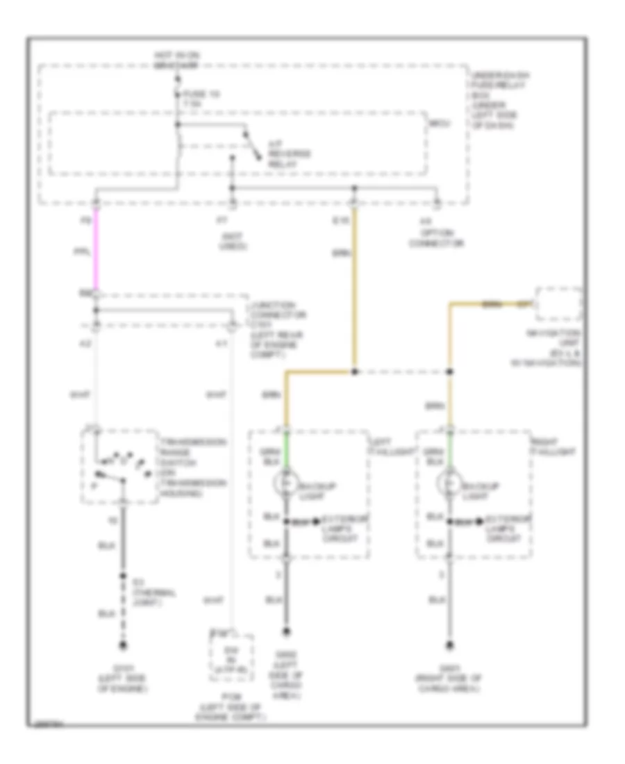
Back-up Lamps Wiring Diagram for Honda CR-V EX 2008
 https://portal-diagnostov.com/license.html
Automotive Electricians Portal FZCO
Automotive Electricians Portal FZCO
https://portal-diagnostov.com/license.html
https://portal-diagnostov.com/license.html
Automotive Electricians Portal FZCO
Automotive Electricians Portal FZCOList of elements for Back-up Lamps Wiring Diagram for Honda CR-V EX 2008:
- (not used)
- A/t reverse relay
- B14
- Backup light
- E15
- Exterior lamps circuit
- Fuse 10 7.5a
- G101 (left side of engine)
- G601 (right side of cargo area)
- G602 (left side of cargo area)
- Hot in on or start
- Junction connector c101 (left rear of engine compt)
- Left taillight
- Micu
- Navigation unit (ex-l & w/ navigation)
- Option connector
- Pcm (left side of engine compt)
- Right taillight
- S3 (thermal joint)
- Sw in (atp-r)
- Transmission range switch (on transmission housing)
- Under-dash fuse/relay box (under left side of dash)
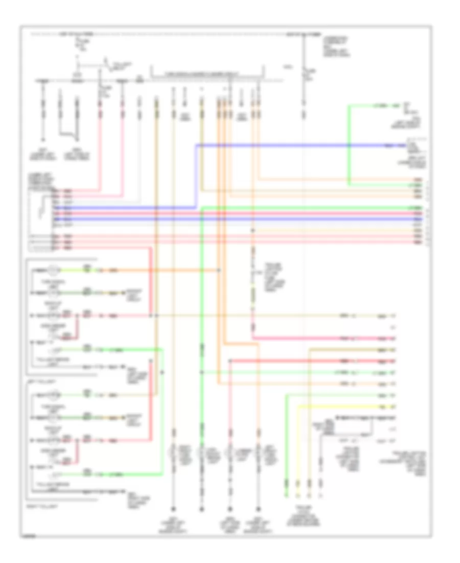
Exterior Lamps Wiring Diagram (1 of 2) for Honda CR-V EX 2008
 https://portal-diagnostov.com/license.html
Automotive Electricians Portal FZCO
Automotive Electricians Portal FZCO
https://portal-diagnostov.com/license.html
https://portal-diagnostov.com/license.html
Automotive Electricians Portal FZCO
Automotive Electricians Portal FZCOList of elements for Exterior Lamps Wiring Diagram (1 of 2) for Honda CR-V EX 2008:
- (not used)
- (under left side of dash) under-dash junction box
- 7.5a
- A13
- A40
- B-can
- Back-up light
- Backup light circuit
- C14
- E11
- E33
- E39
- E40
- F20
- Fuse 15a
- Fuse 20a
- Fuse 7.5a
- G11
- G301 (under left side of engine compt)
- G401 (under left side of dash)
- G601 (right side of cargo area)
- G602 (left side of cargo area)
- High mount brake light
- Hot at all times
- Ig1 ods
- Ind ctrl (ptt)
- Left front turn signal light
- Left taillight
- License plate light
- Micu
- P-gnd
- Pcm (left side of engine compt)
- Pnk
- Red
- Right front turn signal light
- Right taillight
- S-gnd
- Side marker light
- Srs unit (under middle of dash)
- Sw in (bk sw)
- Taillight relay
- Taillight/brake light
- Trailer hitch connector (under center of rear bumper)
- Trailer lighting connector (left side of cargo area)
- Trailer lighting control unit (accessory installed) (left side of cargo area)
- Trailer lighting in-line fuse (left side of cargo area)
- Turn signal light
- Turn signal/hazard flasher circuit
- Under-dash fuse/relay box (under left side of dash)
Exterior Lamps Wiring Diagram (2 of 2) for Honda CR-V EX 2008
 https://portal-diagnostov.com/license.html
Automotive Electricians Portal FZCO
Automotive Electricians Portal FZCO
https://portal-diagnostov.com/license.html
https://portal-diagnostov.com/license.html
Automotive Electricians Portal FZCO
Automotive Electricians Portal FZCOList of elements for Exterior Lamps Wiring Diagram (2 of 2) for Honda CR-V EX 2008:
- (not used)
- (under left side of dash) g501
- +b horn
- 0) off 1) park 2) high beam
- 10v stabilize
- Body controller area network transceiver
- Brake pedal position switch (under left side of dash, on brake pedal support)
- Combi gnd (light)
- Combination light switch
- Dimming circuit
- E34
- F25
- F30
- F31
- Fuse 10a
- Fuse 15a
- G16
- G301 (under left side of engine compt)
- Gauge control module
- H/l on sw
- H/l sw off
- Hazard sw
- Hazard warning switch/passenger's air bag cutoff indicator
- Headlight switch
- Hot at all times
- Interior lights system
- J/c c405 (under left side of dash)
- Left front parking light
- Left turn signal ind
- Lights on ind
- Micu
- Pnk
- Q11
- Red
- Right front parking light
- Right turn signal ind
- S11
- S13
- S18
- S19
- Small lt sw
- Stop sw
- Turn l sw
- Turn r sw
- Turn signal switch
- Turn signal/hazard relay 2 (sounder)
- Under-dash fuse/relay box (under left side of dash)
- Under-hood fuse/relay box (on left side of engine compt)
- Vbu
- Warning drive circuit
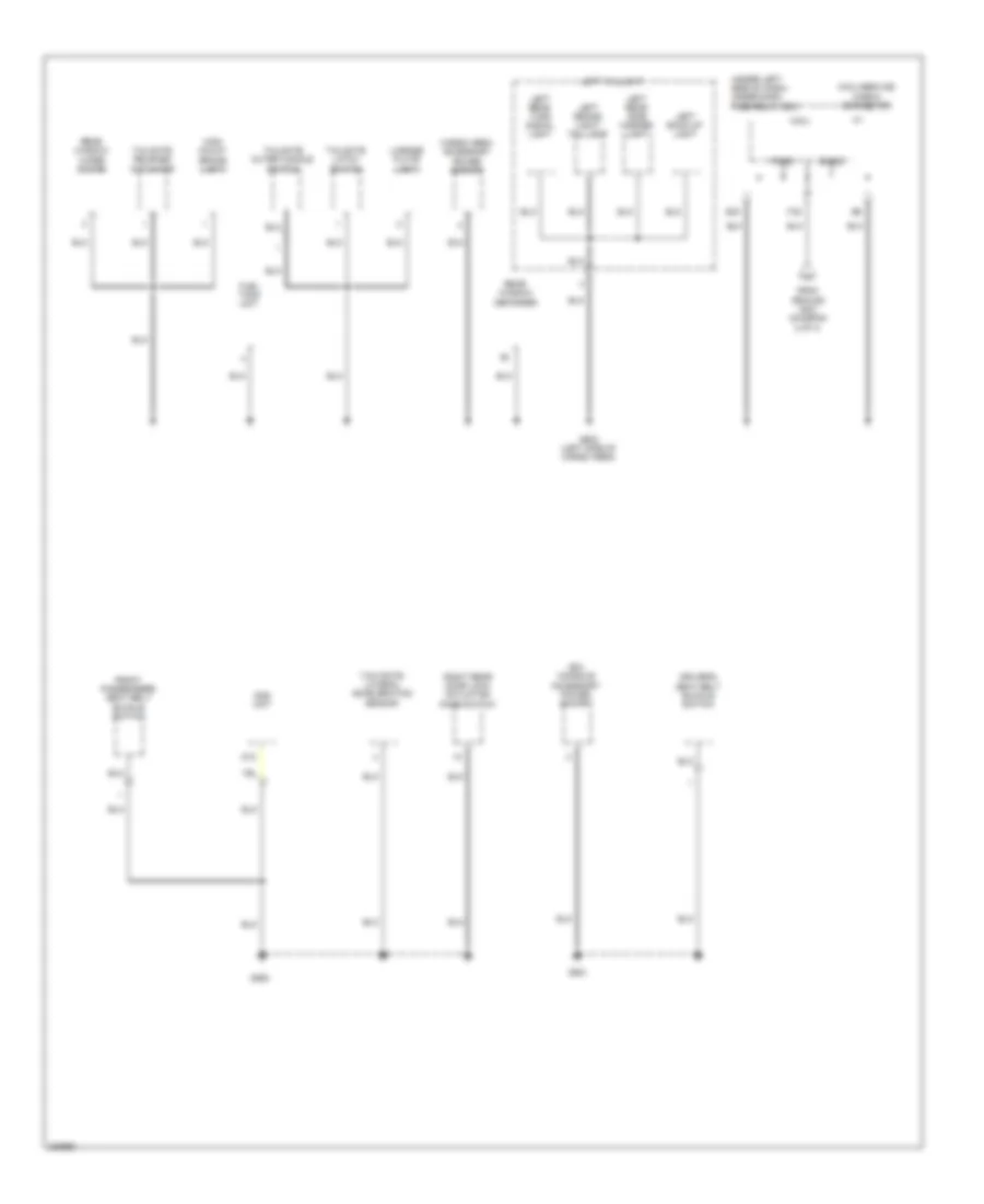
GROUND DISTRIBUTION
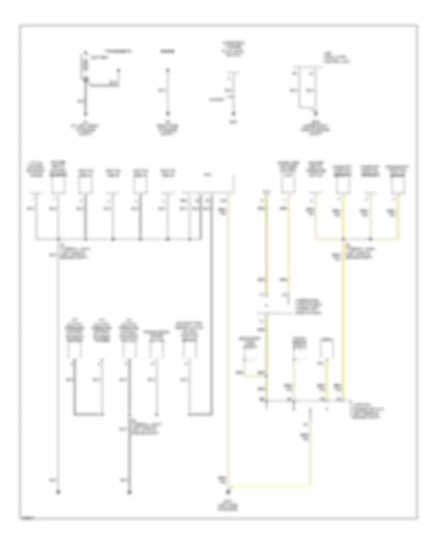
Ground Distribution Wiring Diagram (1 of 4) for Honda CR-V EX 2008
 https://portal-diagnostov.com/license.html
Automotive Electricians Portal FZCO
Automotive Electricians Portal FZCO
https://portal-diagnostov.com/license.html
https://portal-diagnostov.com/license.html
Automotive Electricians Portal FZCO
Automotive Electricians Portal FZCOList of elements for Ground Distribution Wiring Diagram (1 of 4) for Honda CR-V EX 2008:
- A/t clutch pressure control solenoid valve a
- A/t clutch pressure control solenoid valve b
- A/t clutch pressure control solenoid valve c
- B36
- Battery
- C40
- C44
- Camshaft position sensor a
- Camshaft position sensor b
- Canada
- Crankshaft position sensor
- Dlc
- Engine
- Exhaust gas recirculation valve & position sensor
- G1 (at left front of engine compt)
- G101 (left side of engine)
- G2 (right side of engine compt)
- G201
- G202 (under right side of engine compt)
- Ignition coil 1
- Ignition coil 2
- Ignition coil 3
- Ignition coil 4
- Immobilizer keyless control unit
- Junction connector c101 (left rear of engine compt)
- Knock sensor shield
- Pcm
- Rocker arm oil control solenoid
- Rocker arm oil pressure switch
- S1 (thermal joint) (left side of engine compt)
- S2 (thermal joint) (left side of engine compt)
- S3 (thermal joint) (left side of engine compt)
- Secondary ho2s shield
- Transmission
- Transmission range switch
- Under-dash junction box (under left side of dash)
- Vsa modulator control unit
- Vtc oil control solenoid valve
- Windshield washer fluid level switch
Ground Distribution Wiring Diagram (2 of 4) for Honda CR-V EX 2008
 https://portal-diagnostov.com/license.html
Automotive Electricians Portal FZCO
Automotive Electricians Portal FZCO
https://portal-diagnostov.com/license.html
https://portal-diagnostov.com/license.html
Automotive Electricians Portal FZCO
Automotive Electricians Portal FZCOList of elements for Ground Distribution Wiring Diagram (2 of 4) for Honda CR-V EX 2008:
- A/c condenser fan motor
- Blower motor relay
- Brake fluid level switch
- Cable reel (top of steering column)
- Canada
- Cruise control set/resume/ cancel switch
- Driver's door lock actuator/ knob switch/ key cylinder switch
- Eld unit
- Fan control relay
- G301 (under left side of engine compt)
- G302 (under left side of engine compt)
- G401 (under left side of dash)
- G501 (under left side of dash)
- Gauge control module
- Hood switch
- Ignition key switch/ light
- Left front parking light
- Left front turn signal light
- Left headlight
- Left power mirror
- Moonroof motor/ control unit
- Moonroof switch
- Power mirror defogger relay
- Power mirror switch
- Power steering pressure switch
- Power transistor
- Power window master switch/ driver's door lock switch
- Rear window wiper motor relay
- Right front parking light
- Right front turn signal light
- Right headlight
- Steering wheel
- To under-dash fuse/relay box (diagram 4 of 4)
- Under-hood fuse/relay box (on left side of engine compartment)
- Vsa off switch
- Windshield wiper motor
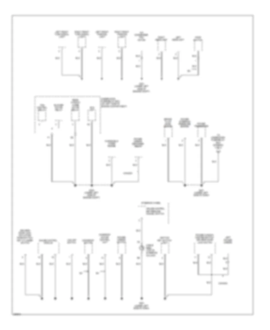
Ground Distribution Wiring Diagram (3 of 4) for Honda CR-V EX 2008
 https://portal-diagnostov.com/license.html
Automotive Electricians Portal FZCO
Automotive Electricians Portal FZCO
https://portal-diagnostov.com/license.html
https://portal-diagnostov.com/license.html
Automotive Electricians Portal FZCO
Automotive Electricians Portal FZCOList of elements for Ground Distribution Wiring Diagram (3 of 4) for Honda CR-V EX 2008:
- (under left side of dash) under-dash fuse/relay box
- (w/o navigation) audio unit
- A22
- A23
- Cargo area accessory power socket relay
- Console accessory power socket relay
- D3 switch
- D3 switch/ park-pin switch
- Dlc
- Front accessory power socket
- Front accessory power socket relay
- Front passenger's door lock actuator/ knob switch
- Front passenger's power window switch
- G502 (under middle of dash)
- G503 (under middle of dash)
- G504 (under middle of dash)
- G505 (under middle of dash)
- G601 (right side of cargo area)
- Glove box light
- Hvac control unit
- Left rear door lock actuator/ knob switch
- Mes connector
- Micu
- Park-pin switch
- Right back-up light
- Right brake light/ taillight
- Right power mirror
- Right rear side marker light
- Right rear turn signal light
- Right taillight
- S gnd2
- Srs unit
- T34
- Tpms control unit
- Trailer lighting connector
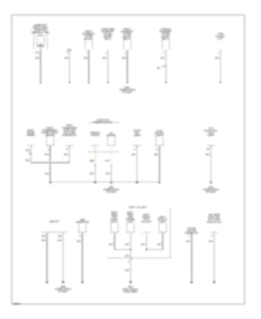
Ground Distribution Wiring Diagram (4 of 4) for Honda CR-V EX 2008
 https://portal-diagnostov.com/license.html
Automotive Electricians Portal FZCO
Automotive Electricians Portal FZCO
https://portal-diagnostov.com/license.html
https://portal-diagnostov.com/license.html
Automotive Electricians Portal FZCO
Automotive Electricians Portal FZCOList of elements for Ground Distribution Wiring Diagram (4 of 4) for Honda CR-V EX 2008:
- (ex) console accessory power socket
- (under left side of dash) under-dash fuse/relay box
- Cargo area accessory power socket
- D12
- Driver's seat belt buckle switch
- E33
- F20
- From ground g401 (diagram 2 of 4)
- Front passenger's seat belt buckle switch
- Fuel tank unit
- G551
- G552
- G602 (left side of cargo area)
- High mount brake light
- Left back-up light
- Left brake light/ taillight
- Left rear side marker light
- Left rear turn signal light
- Left taillight
- License plate light
- Micu
- Micu service check connector
- Ods unit
- P-gnd
- Rear window defogger
- Rear window wiper motor
- Right rear door lock actuator/ knob switch
- S-gnd
- Tailgate latch switch
- Tailgate outer handle switch
- Tailgate release actuator
- Yaw rate- lateral acceleration sensor
HEADLIGHTS
Headlights Wiring Diagram for Honda CR-V EX 2008
 https://portal-diagnostov.com/license.html
Automotive Electricians Portal FZCO
Automotive Electricians Portal FZCO
https://portal-diagnostov.com/license.html
https://portal-diagnostov.com/license.html
Automotive Electricians Portal FZCO
Automotive Electricians Portal FZCOList of elements for Headlights Wiring Diagram for Honda CR-V EX 2008:
- (not used)
- +b h/l hi-r
- 0 = off 1 = high 2 = passing
- 0 = off 1 = lights on 2 = high beam
- 0 = off 1 = on
- 10v stabilize
- B-can
- Body controller area network transceiver
- Combi gnd
- Combination light switch
- Controller
- Dim sw
- Dimmer/flash- to-pass switch
- Dimming circuit
- Drl control circuit
- Drl ind
- E33
- F20
- F21
- F22
- Fog light relay (honda accessory) (under left side of dash)
- Fog light switch
- Fog lt sw
- Fr fog rly
- Fuse 10 7.5a
- Fuse 12 10a
- Fuse 13 10a
- Fuse 16 10a
- Fuse 17 10a
- Fuse 18 20a
- Fuse 21 20a
- Fuse 23 10a
- Fuse 37 7.5a
- Fuse 6 20a
- G10
- G15
- G17
- G301 (under left side of engine compt)
- G401 (under left side of dash)
- G602 (left side of cargo area)
- Gauge control module
- H/l on sw
- H/l sw off
- Headlight switch
- High beam control circuit
- High beam ind
- Honda accessory
- Hot at all times
- Hot in on
- Hot in on or start
- Ig1
- J/c c405 (under left side of dash)
- Left fog light
- Left headlight
- Lights on ind
- Low beam headlight relay
- Micu
- P-gnd
- P10
- Parking brake switch (under left side of dash)
- Passing sw
- Pnk
- Right fog light
- Right headlight
- S-gnd
- S11
- S12
- S13
- S14
- S16
- Small lt sw
- Under-dash fuse/relay box (under left side of dash)
- Under-dash junction box (under left side of dash)
- Under-hood fuse/relay box (on left side of engine compt)
- Vbu
- Warning drive circuit
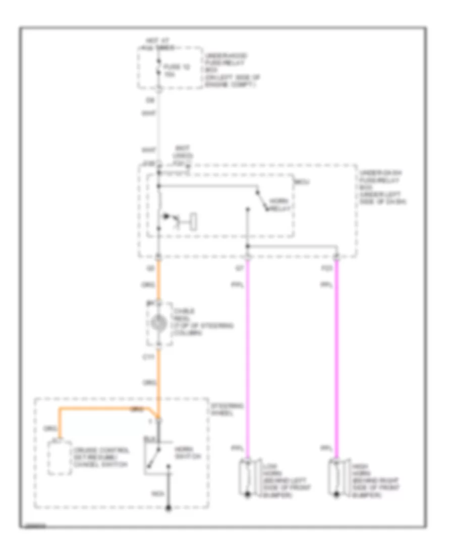
HORN
Horn Wiring Diagram for Honda CR-V EX 2008
 https://portal-diagnostov.com/license.html
Automotive Electricians Portal FZCO
Automotive Electricians Portal FZCO
https://portal-diagnostov.com/license.html
https://portal-diagnostov.com/license.html
Automotive Electricians Portal FZCO
Automotive Electricians Portal FZCOList of elements for Horn Wiring Diagram for Honda CR-V EX 2008:
- (not used) f31
- C11
- Cable reel (top of steering column)
- Cruise control set/resume/ cancel switch
- F23
- Fuse 12 15a
- G16
- High horn (behind right side of front bumper)
- Horn relay
- Horn switch
- Hot at all times
- Low horn (behind left side of front bumper)
- Micu
- Nca
- Steering wheel
- Under-dash fuse/relay box (under left side of dash)
- Under-hood fuse/relay box (on left side of engine compt)
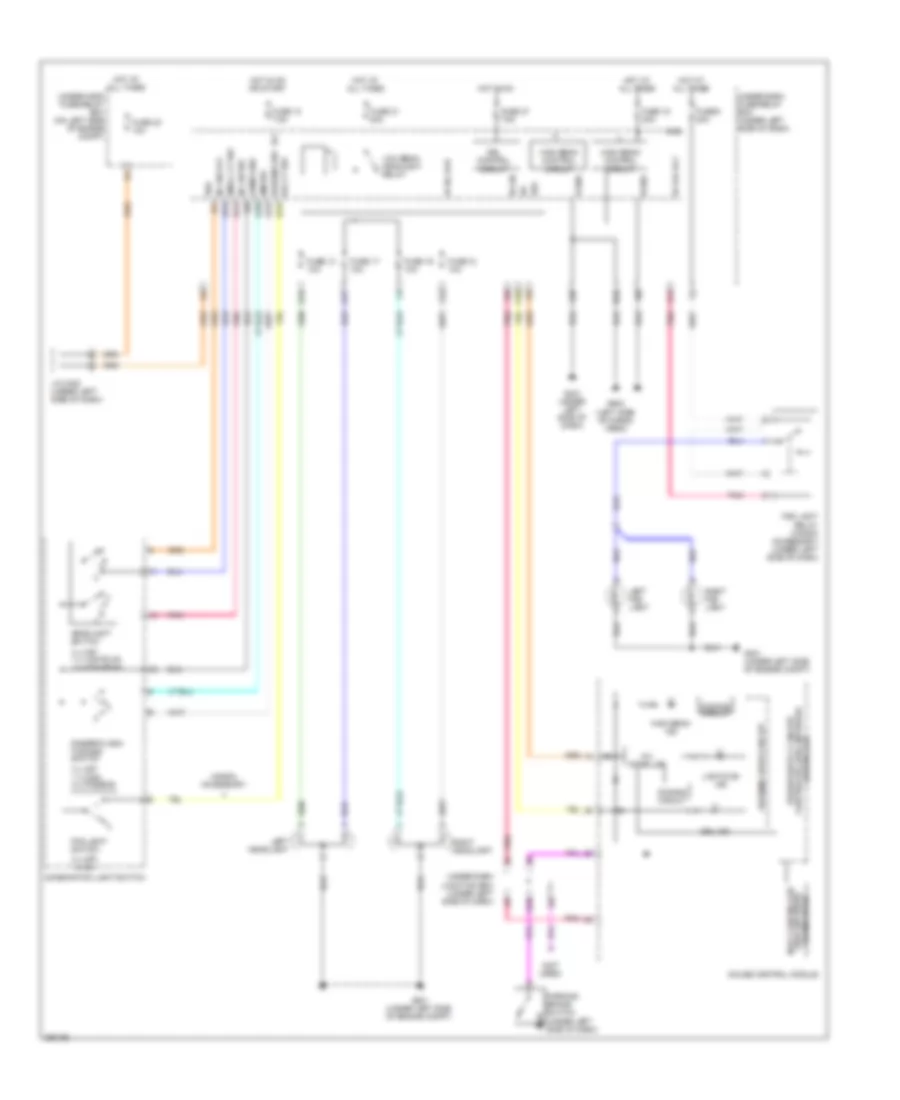
INSTRUMENT CLUSTER
Instrument Cluster Wiring Diagram (1 of 2) for Honda CR-V EX 2008
 https://portal-diagnostov.com/license.html
Automotive Electricians Portal FZCO
Automotive Electricians Portal FZCO
https://portal-diagnostov.com/license.html
https://portal-diagnostov.com/license.html
Automotive Electricians Portal FZCO
Automotive Electricians Portal FZCOList of elements for Instrument Cluster Wiring Diagram (1 of 2) for Honda CR-V EX 2008:
- (not used)
- A/t gear position ind drive circuit
- Abs ind
- Anti-lock brakes system
- Blinking
- Brake fluid level switch (on brake fluid reservoir)
- Brake system ind
- Charging system ind
- Circuit
- Compulsory turning-off circuit
- Compulsory turning-on circuit
- Computer data lines system
- Cruise control system
- Drl ind
- E17
- E36
- E37
- Exterior lights system
- Fail-safe circuit
- Fr dr sw (as)
- Fr dr sw (dr)
- Front passenger's door switch (on right "b" pillar)
- Fuel gauge sending unit
- Fuel tank unit (top of fuel tank)
- Fuse 7.5a
- G10
- G401 (under left side of dash)
- G501 (under left side of dash)
- Gauge control module
- Hot in on or start
- Ig1
- Interior lights system
- Low fuel ind
- Low oil pressure ind
- Low tire pressure ind
- Low washer fluid ind (canada)
- Maintenance required ind
- Micu
- Mil ind
- Outside air temperature sensor (ex-l) (behind middle of front bumper)
- P10
- Parking brake switch (under left side of dash)
- Pnk
- Red
- Rr dr sw (as)
- Rr dr sw (dr)
- Seat belt reminder ind
- Security ind (ex & ex-l)
- Side air bag cut-off ind
- Srs ind
- T/g sw
- To high beam ind (diagram 2 of 2)
- Tpms ind
- Under-dash fuse/relay box (under left side of dash)
- Under-dash junction box (under left side of dash)
- Vbu
- Vsa activation ind
- Vsa system ind
- Warning drive circuit
- Wiper/washer system
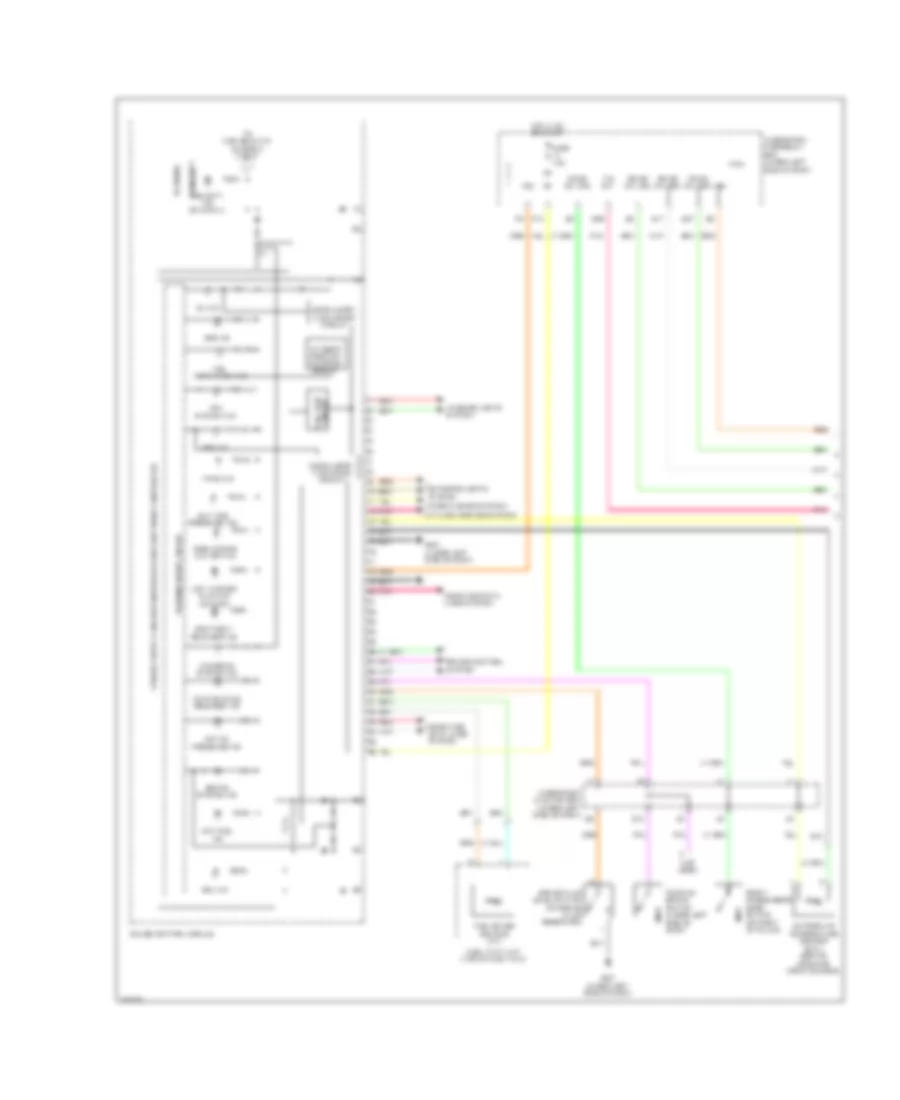
Instrument Cluster Wiring Diagram (2 of 2) for Honda CR-V EX 2008
 https://portal-diagnostov.com/license.html
Automotive Electricians Portal FZCO
Automotive Electricians Portal FZCO
https://portal-diagnostov.com/license.html
https://portal-diagnostov.com/license.html
Automotive Electricians Portal FZCO
Automotive Electricians Portal FZCOList of elements for Instrument Cluster Wiring Diagram (2 of 2) for Honda CR-V EX 2008:
- (engine coolant temperature gauge)
- (fuel gauge)
- (sounder) relay 2 hazard turn signal/
- 10v stabilize
- A/t ind dimming circuit
- A36 communication sig high (can-h)
- A37 communication sig low (can-l)
- Beeper
- Body controller area network transceiver
- Circuit dimming
- Computer data lines system
- Coolant temperature gauge (lcd)
- Cruise control ind
- Cruise control main switch ind
- Dimming circuit
- Door & tailgate open monitor
- Drive circuit
- Driver's door switch (on left "b" pillar)
- Fast controller area network transceiver
- From security ind (diagram 1 of 2)
- Fuel gauge (lcd)
- Fuse 10a
- G602 (left side of cargo area)
- Gauge control module
- High beam ind
- Hot at all times
- Illumination control for dial (white)
- Illumination control for ft lcd (white)
- Illumination control for lcd (amber)
- Illumination control for lcd (white)
- Illumination control for pointers (red)
- Illumination volume
- Immobilizer system ind
- Ind drive circuit a/t gear position
- J/c c405 (under left side of dash)
- Left rear door switch (in left "c" pillar)
- Left turn signal ind
- Lights on ind
- Multi- information display (mid) unit
- Oil pressure switch (on right front of engine, above oil filter)
- Pcm (left side of engine compt)
- Pnk
- Red
- Right rear door switch (in right "c" pillar)
- Right turn signal ind
- Select/reset/ brightness control knob
- Speedometer
- Sw in (opsw)
- Tachometer
- Tailgate latch switch (bottom of tailgate)
- Under-hood fuse/relay box (on left side of engine compt)
- Unit control 5v
- Warning drive circuit
INTERIOR LIGHTS
Courtesy Lamps Wiring Diagram for Honda CR-V EX 2008
 https://portal-diagnostov.com/license.html
Automotive Electricians Portal FZCO
Automotive Electricians Portal FZCO
https://portal-diagnostov.com/license.html
https://portal-diagnostov.com/license.html
Automotive Electricians Portal FZCO
Automotive Electricians Portal FZCOList of elements for Courtesy Lamps Wiring Diagram for Honda CR-V EX 2008:
- (lx) front individual map lights
- +b int lt
- +b intr lts
- Cargo area light
- Cargo lt-
- Ceiling light
- Door
- Driver's door switch (on left "b" pillar)
- E16
- E17
- E36
- E37
- E38
- Fr door sw(as)
- Fr door sw(dr)
- Front individual map lights
- Front passenger's door switch (on right "b" pillar)
- Fuse 7.5a
- G602 (left side of cargo area)
- Hot at all times
- Ignition key switch
- Interior light switch
- Intr lt-
- Key lt-
- Left rear door switch (in left "c" pillar)
- Micu
- Moonroof switch (ex & ex-l)
- Off
- Pnk
- R10
- R13
- Red
- Right rear door switch (in right "c" pillar)
- Rr door sw(as)
- Rr door sw(dr)
- T/g sw
- Tailgate latch switch (bottom of tailgate)
- Under- dash junction box (under left side of dash)
- Under-dash fuse/ relay box (under left side of dash)
- Under-hood fuse/relay box (on left side of engine compt)
Entry Light Timer Wiring Diagram for Honda CR-V EX 2008
 https://portal-diagnostov.com/license.html
Automotive Electricians Portal FZCO
Automotive Electricians Portal FZCO
https://portal-diagnostov.com/license.html
https://portal-diagnostov.com/license.html
Automotive Electricians Portal FZCO
Automotive Electricians Portal FZCOList of elements for Entry Light Timer Wiring Diagram for Honda CR-V EX 2008:
- (lx) front individual map lights
- +b intrlts
- B-can
- Cargo area light
- Ceiling light
- Door
- Door lock knob
- Driver's door lock actuator/ knob switch key cylinder switch (in driver's door)
- Driver's door lock knob switch
- Driver's door switch (on left "b" pillar)
- E16
- E17
- E36
- E37
- E38
- Fr door sw(as)
- Fr door sw(dr)
- Front individual map lights
- Front passenger's door switch (on right "b" pillar)
- Fuse 10a
- Fuse 7.5a
- G501 (under left side of dash)
- G602 (left side of cargo area)
- Hot at all times
- Ig key sw
- Ignition key switch
- Immobilizer keyless control unit (on steering column, integral to ignition switch)
- Interior light switch
- Intr lt-
- Junction connector c405 (under left side of dash)
- Key
- Left rear door switch (in left "c" pillar)
- Micu
- Moonroof switch (ex & ex-l)
- Off
- Pnk
- R16
- Right rear door switch (in right "c" pillar)
- Rr door sw(as)
- Rr door sw(dr)
- Sil dr lock
- Sil dr unlock
- T/g sw
- T23
- T24
- Tailgate latch switch (bottom of tailgate)
- Under- dash junction box (under left side of dash)
- Under-dash fuse/ relay box (under left side of dash)
- Under-dash junction box (under left side of dash)
- Under-hood fuse/relay box (on left side of engine compt)
- Vbu
Instrument Illumination Wiring Diagram (1 of 2) for Honda CR-V EX 2008
 https://portal-diagnostov.com/license.html
Automotive Electricians Portal FZCO
Automotive Electricians Portal FZCO
https://portal-diagnostov.com/license.html
https://portal-diagnostov.com/license.html
Automotive Electricians Portal FZCO
Automotive Electricians Portal FZCOList of elements for Instrument Illumination Wiring Diagram (1 of 2) for Honda CR-V EX 2008:
- (light) s5
- (not used)
- A10
- Ambient light
- Audio unit
- B-can
- C11
- C12
- Combi gnd
- Combination light switch
- D3 switch/ park-pin switch (under middle of dash)
- E16
- E26
- E33
- Ex & ex-l
- Ex-l & w/ navigation
- F10
- F20
- Front passenger's seat heater switch (ex-l)
- Fuse 10 7.5a
- G401 (under left side of dash)
- G503 (under middle of dash)
- G602 (left side of cargo area)
- Glove box light
- H/l off
- H/l on
- Hazard warning switch/ passenger's air bag cutoff indicator
- Head
- Headlight switch
- Hot in on or start
- Ig1
- Illum-
- J11
- J14
- J21
- J22
- K13
- Lx, ex, ex-l & w/o navigation
- Micu
- Moonroof switch (ex & ex-l)
- Navigation unit
- Off
- Option connector
- P-gnd
- Park
- Pnk
- Power mirror switch
- Q13
- Red
- S-gnd
- Small lt
- Sw s1
- Sw s11
- Sw s13
- Under-dash fuse/relay box (under left side of dash)
- Under-dash junction box (under left side of dash)
- Vsa off switch
Instrument Illumination Wiring Diagram (2 of 2) for Honda CR-V EX 2008
 https://portal-diagnostov.com/license.html
Automotive Electricians Portal FZCO
Automotive Electricians Portal FZCO
https://portal-diagnostov.com/license.html
https://portal-diagnostov.com/license.html
Automotive Electricians Portal FZCO
Automotive Electricians Portal FZCOList of elements for Instrument Illumination Wiring Diagram (2 of 2) for Honda CR-V EX 2008:
- (not used)
- +b small
- 10v stabilize
- Ambient light
- Area network transceiver body controller
- Audio remote switch
- B10
- Cable reel (top of steering column)
- Climate control unit (ex-l)
- Cruise control set/ resume/ cancel switch
- Driver's seat heater switch (ex-l)
- E25
- Ex & ex-l
- Ex-l
- Fuse 14 7.5a
- Fuse 19 15a
- Fuse 23 10a
- G501 (under left side of dash)
- Gauge control module
- Hot at all times
- Hvac control unit (lx & ex)
- Illumi +
- Illumination control for dial (white)
- Illumination control for ft lcd (white)
- Illumination control for lcd (amber)
- Illumination control for lcd (white)
- Illumination control for pointers (red)
- Junction connector c405 (under left side of dash)
- Lx & ex
- Micu
- Option connector
- P10
- Pnk
- Q12
- Red
- Steering wheel
- Taillight relay
- Under-dash fuse/relay box (under left side of dash)
- Under-hood fuse/relay box (on left side of engine compt)
- Vbu
- Voice control switch (ex-l & w/ navigation)
- Volume illumination
NAVIGATION
Navigation Wiring Diagram (1 of 3) for Honda CR-V EX 2008
 https://portal-diagnostov.com/license.html
Automotive Electricians Portal FZCO
Automotive Electricians Portal FZCO
https://portal-diagnostov.com/license.html
https://portal-diagnostov.com/license.html
Automotive Electricians Portal FZCO
Automotive Electricians Portal FZCOList of elements for Navigation Wiring Diagram (1 of 3) for Honda CR-V EX 2008:
- (behind right kick panel) j/c c509
- (under left side of dash) j/c c405
- A10
- A11
- A12
- A13
- A14
- A15
- A16
- A17
- Ac-ck
- Ac-si
- Ac-so
- Acc
- Am/fm/xm antenna
- Amp on
- Amplifier
- Ant +b
- Antenna amplifier
- Audio l+
- Audio l-
- Audio r+
- Audio r-
- Audio remote gnd
- Audio remote sw
- Aux del
- Aux gnd
- Aux l
- Aux r
- Aux sgnd
- B10
- B11
- B12
- B13
- B14
- B15
- B16
- B17
- B18
- B19
- B20
- B21
- B22
- Back lt-
- Bus shld
- Bus+
- Bus-
- C10
- C11
- C12
- Camera (rc)
- Camera adpt
- Camera gnd
- Camera shield
- Camera v
- Cd changer
- Climate control unit
- Computer data lines system
- E10
- E11
- E12
- E13
- E14
- Exterior lights system
- Fr left (+)
- Fr left (-)
- Fr right (+)
- Fr right (-)
- Fuse 17 15a
- Fuse 23 10a
- G502 (under middle of dash)
- G504 (under middle of dash)
- Gnd
- Gps
- Gps antenna
- Gps shield
- Hft navi guide
- Hot at all times
- Ill+
- Ill-
- Interior lights system
- K-line
- Mic adpt
- Mic gnd
- Mic out shld
- Mic sig+
- Microphone (in roof console)
- Navigation unit
- Nca
- Pnk
- Radio gnd
- Rearview camera circuit
- Red
- Rr left (+)
- Rr left (-)
- Rr right (+)
- Rr right (-)
- Scty radio
- Shield (am/fm)
- Shield gnd
- Shld gnd
- Shld xm
- Sig
- Sys acc
- Under-hood fuse/relay box (on left side of engine compt)
- Vbu
- Vcc
- Vsp
- Xm receiver (usa)
Navigation Wiring Diagram (2 of 3) for Honda CR-V EX 2008
 https://portal-diagnostov.com/license.html
Automotive Electricians Portal FZCO
Automotive Electricians Portal FZCO
https://portal-diagnostov.com/license.html
https://portal-diagnostov.com/license.html
Automotive Electricians Portal FZCO
Automotive Electricians Portal FZCOList of elements for Navigation Wiring Diagram (2 of 3) for Honda CR-V EX 2008:
- (not used)
- +b d/l
- Acc radio
- Am/fm antenna
- Am/fm antenna lead connector
- Am/fm antenna sub-lead connector
- Am/fm/xm antenna (usa) am/fm antenna (canada)
- Antenna amplifier
- Audio remote switch
- Aux det
- Aux gnd
- Aux l ch
- Aux r ch
- Aux sgnd
- Auxiliary jack assembly
- B18
- Back switch
- C10
- C18
- Cable reel (top of steering column)
- Channel down switch
- Channel up switch
- Fuse 34 7.5a
- Hot in acc or on
- Interior lights system
- Micu
- Mode switch
- Nca
- Pnk
- R17
- Radio sw
- Red
- Steering wheel
- Talk switch
- Under-dash fuse/relay box (under left side of dash)
- Vbu
- Voice control switch
- Volume down switch
- Volume up switch
Navigation Wiring Diagram (3 of 3) for Honda CR-V EX 2008
 https://portal-diagnostov.com/license.html
Automotive Electricians Portal FZCO
Automotive Electricians Portal FZCO
https://portal-diagnostov.com/license.html
https://portal-diagnostov.com/license.html
Automotive Electricians Portal FZCO
Automotive Electricians Portal FZCOList of elements for Navigation Wiring Diagram (3 of 3) for Honda CR-V EX 2008:
- (behind
- +b audio amp
- A10
- A11
- A12
- A13
- A14
- A15
- A16
- A17
- A18
- A19
- A20
- A29
- Acc radio
- Amp on
- B10
- B11
- B12
- B13
- B14
- Fl sig shield
- Fl sig+
- Fl sig-
- Fr l spkr+
- Fr l spkr-
- Fr r spkr+
- Fr r spkr-
- Fr sig shield
- Fr sig+
- G13
- G504 (under middle of dash)
- Glove box)
- Gnd
- Immobilizer- keyless control unit (on steering column, integral to ignition switch)
- J/c c510
- L10
- Left front speaker
- Left rear speaker
- Left tweeter
- Moonroof control unit (ex & ex-l) (center of roof) moonroof motor (ex & ex-l) (middle of roof)
- Pcm (left side of engine compt) out
- Pnk
- Red
- Right front speaker
- Right rear speaker
- Right tweeter
- Rl sig shield
- Rl sig-
- Rr l spkr+
- Rr l spkr-
- Rr r spkr+
- Rr r spkr-
- Rr sig shield
- Rr sig+
- Rr sig-
- Stereo amplifier (under middle of dash)
- Subwoofer
- Under-dash junction box (under left side of dash)
- Vsp
- Vsp-
- Woofer+
- Woofer-
Parking Assistant Wiring Diagram for Honda CR-V EX 2008
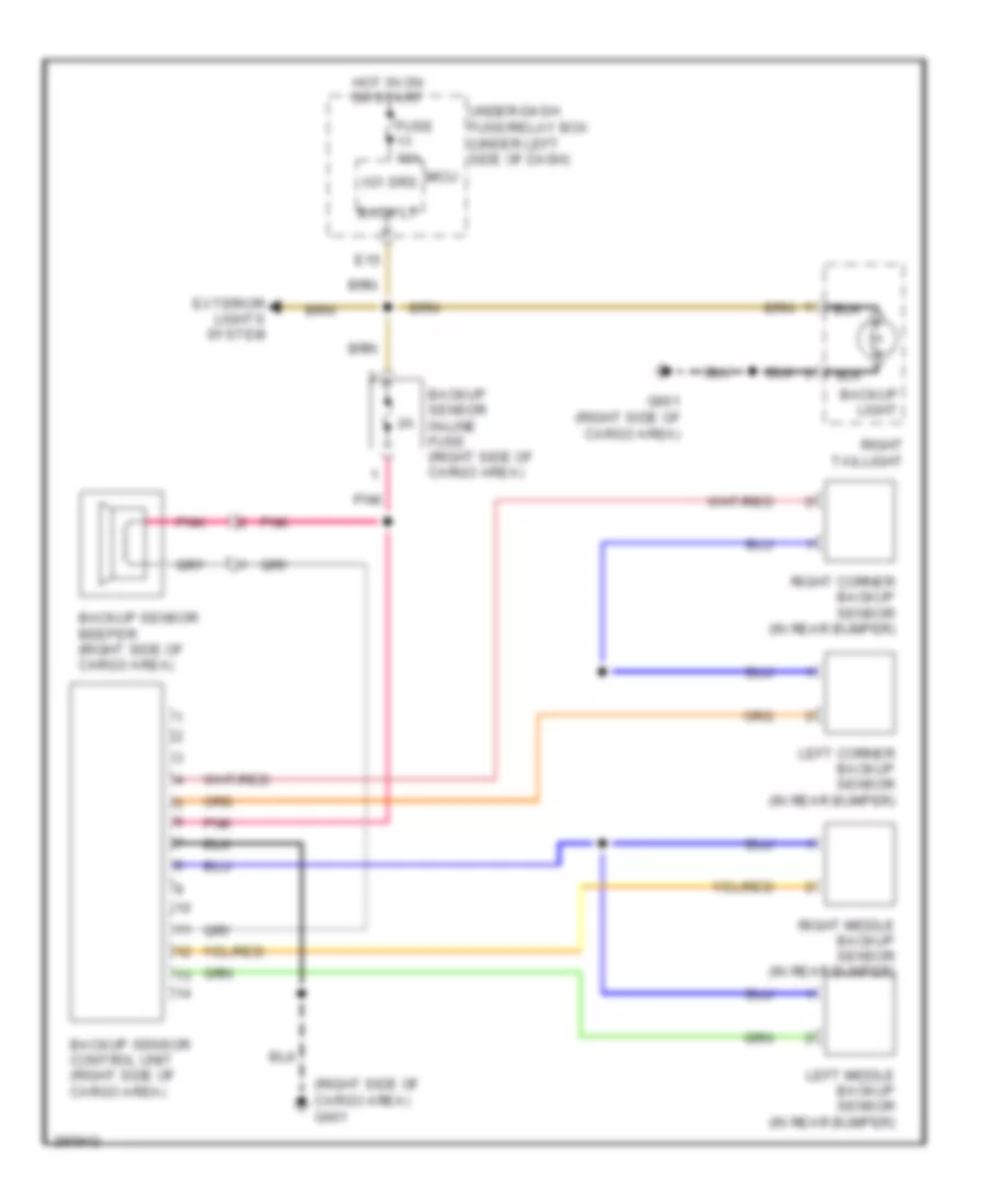 https://portal-diagnostov.com/license.html
Automotive Electricians Portal FZCO
Automotive Electricians Portal FZCO
https://portal-diagnostov.com/license.html
https://portal-diagnostov.com/license.html
Automotive Electricians Portal FZCO
Automotive Electricians Portal FZCOList of elements for Parking Assistant Wiring Diagram for Honda CR-V EX 2008:
- (right side of cargo area) g601
- Back lt
- Backup light
- Backup sensor beeper (right side of cargo area)
- Backup sensor control unit (right side of cargo area)
- Backup sensor in-line fuse (right side of cargo area)
- E15
- Exterior lights system
- Fuse 10a
- G601 (right side of cargo area)
- Hot in on or start
- Ig1 srs
- Left corner backup sensor (in rear bumper)
- Left middle backup sensor (in rear bumper)
- Micu
- Pnk
- Right corner backup sensor (in rear bumper)
- Right middle backup sensor (in rear bumper)
- Right taillight
- Under-dash fuse/relay box (under left side of dash)
Rear Camera Wiring Diagram for Honda CR-V EX 2008
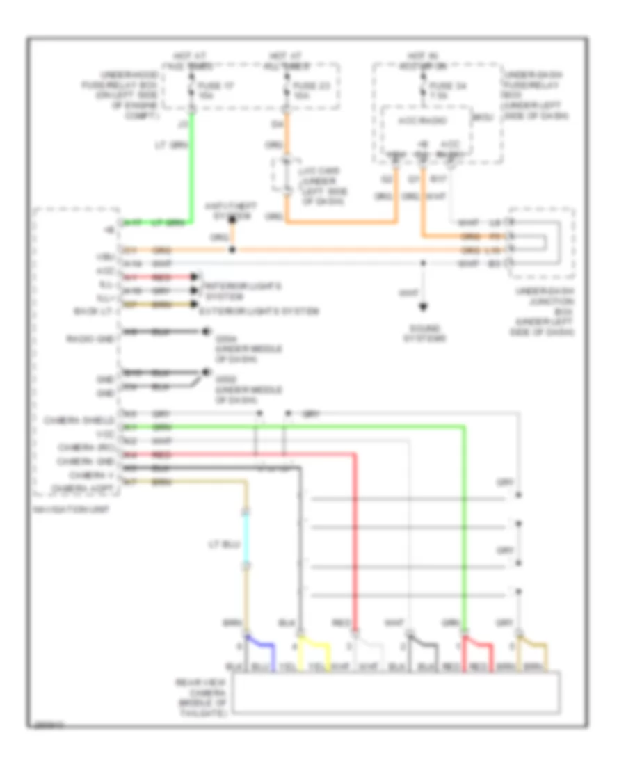 https://portal-diagnostov.com/license.html
Automotive Electricians Portal FZCO
Automotive Electricians Portal FZCO
https://portal-diagnostov.com/license.html
https://portal-diagnostov.com/license.html
Automotive Electricians Portal FZCO
Automotive Electricians Portal FZCOList of elements for Rear Camera Wiring Diagram for Honda CR-V EX 2008:
- +b d/l
- A10
- A14
- A17
- Acc
- Acc radio
- Anti-theft system
- B15
- Back lt-
- Camera (rc)
- Camera adpt
- Camera gnd
- Camera shield
- Camera v
- Exterior lights system
- Fuse 17 15a
- Fuse 23 10a
- Fuse 34 7.5a
- G502 (under middle of dash)
- G504 (under middle of dash)
- Gnd
- Hot at all times
- Hot in acc or on
- Ill+
- Ill-
- Interior lights system
- J/c c405 (under left side of dash)
- L10
- Micu
- Navigation unit
- R17
- Radio gnd
- Rear view camera (middle of tailgate)
- Red
- Sound systems
- Under-dash fuse/relay box (under left side of dash)
- Under-dash junction box (under left side of dash)
- Under-hood fuse/relay box (on left side of engine compt)
- Vbu
- Vcc
POWER DISTRIBUTION
Power Distribution Wiring Diagram (1 of 3) for Honda CR-V EX 2008
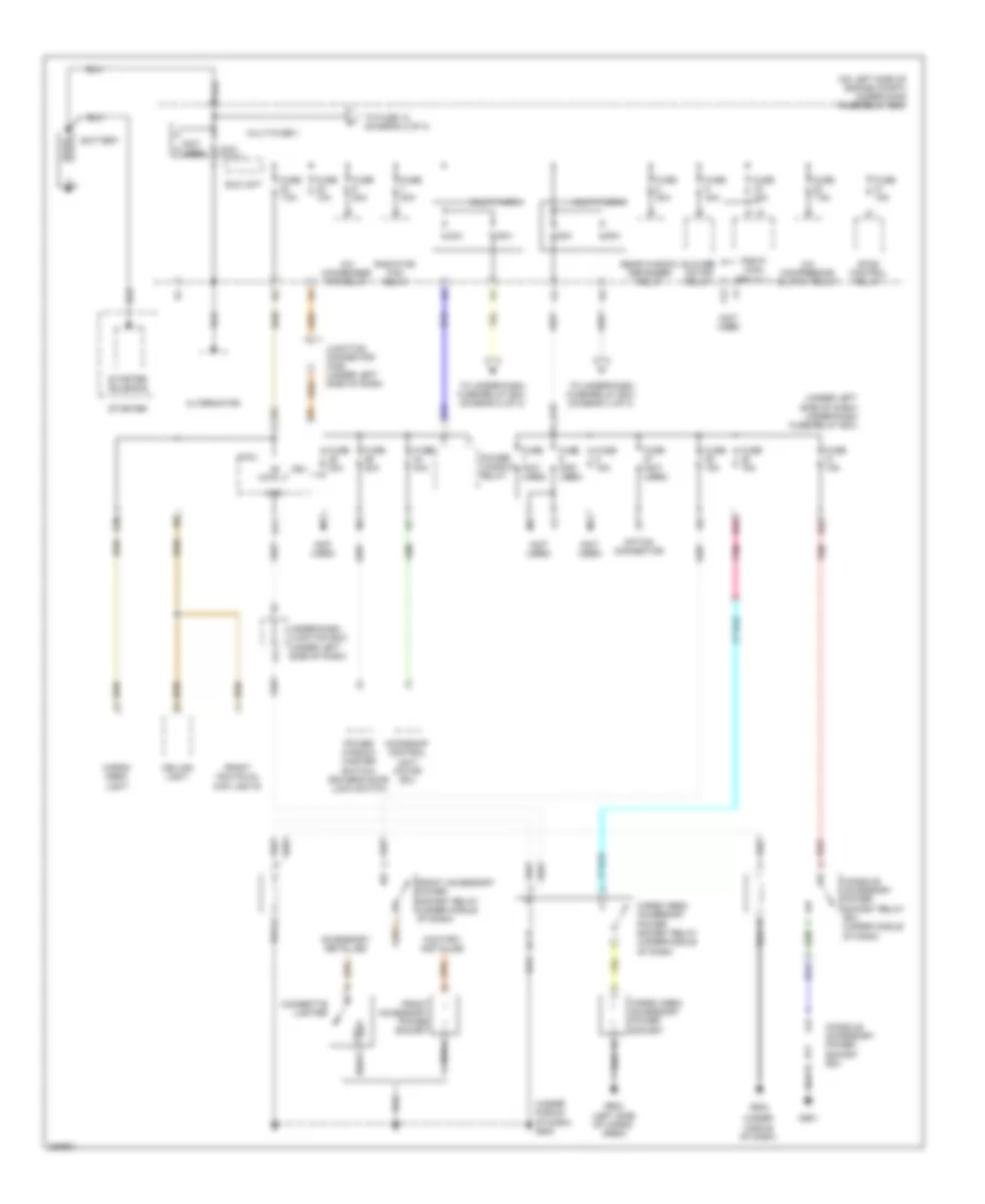 https://portal-diagnostov.com/license.html
Automotive Electricians Portal FZCO
Automotive Electricians Portal FZCO
https://portal-diagnostov.com/license.html
https://portal-diagnostov.com/license.html
Automotive Electricians Portal FZCO
Automotive Electricians Portal FZCOList of elements for Power Distribution Wiring Diagram (1 of 3) for Honda CR-V EX 2008:
- (not used)
- (on left side of engine compt) under-hood fuse/relay box
- (under left side of dash) under-dash fuse/relay box
- (under middle of dash)
- (under middle of dash) g502
- +b intr lt
- 100a
- 40a
- 50a
- 80a
- A/c compressor clutch relay
- A/c condenser fan relay
- Acc
- Accessory installed
- Alternator
- Battery
- Blower motor relay
- Cargo area accessory power socket
- Cargo area accessory power socket relay (under middle of dash)
- Cargo area light
- Ceiling light
- Cigarette lighter
- Console accessory power socket (ex)
- Console accessory power socket relay (ex) (under middle of dash)
- E22
- E35
- E38
- Eld unit
- Etcs control relay
- F13
- Factory installed
- Front accessory power socket
- Front accessory power socket relay (under middle of dash)
- Front individual map lights
- Fuse (not used)
- Fuse 10a
- Fuse 15a
- Fuse 20a
- Fuse 30a
- Fuse 40a
- Fuse 7.5a
- G19
- G21
- G502
- G551
- G602 (left side of cargo area)
- Junction connector c405 (under left side of dash)
- Micu
- Moonroof control unit/ motor (ex)
- Multi-fuse 1
- Multi-fuse 2
- Multi-fuse 4
- Option connector
- Pgm-fi main relay 1
- Pnk
- Power window master switch/ driver's door lock switch
- Power window relay
- R17
- Radiator fan relay
- Rear window defogger relay
- Red
- Starter
- Starter solenoid
- To fuse 10 (diagram 2 of 3)
- To under-dash fuse/relay box (diagram 2 of 3)
- To under-dash fuse/relay box (diagram 3 of 3)
- Under-dash junction box (under left side of dash)
- Vbu
Power Distribution Wiring Diagram (2 of 3) for Honda CR-V EX 2008
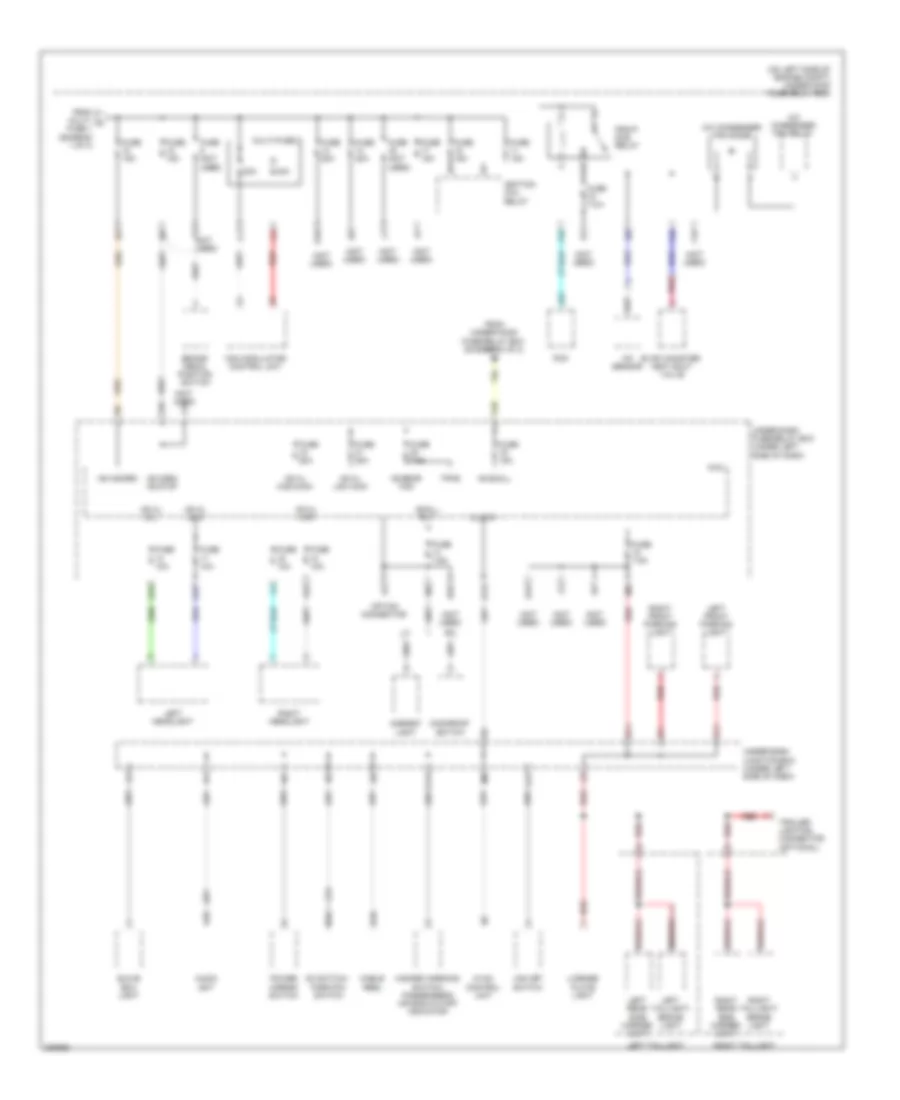 https://portal-diagnostov.com/license.html
Automotive Electricians Portal FZCO
Automotive Electricians Portal FZCO
https://portal-diagnostov.com/license.html
https://portal-diagnostov.com/license.html
Automotive Electricians Portal FZCO
Automotive Electricians Portal FZCOList of elements for Power Distribution Wiring Diagram (2 of 3) for Honda CR-V EX 2008:
- (not used)
- (on left side of engine compt) under-hood fuse/relay box
- +b h/l hi-l
- +b h/l hi-r
- +b h/l high main
- +b h/l low
- +b h/l low main
- +b hazard
- +b horn +b stop
- +b rear fog
- +b small
- 20a
- 40a
- A/c condenser fan diode
- A/c condenser fan relay
- A/f sensor
- A10
- A21
- Ambient light
- Audio unit
- B10
- Brake pedal position switch
- C11
- Cable reel
- D3 switch/ park-pin switch
- E10
- E11
- E19
- E25
- Evap canister vent shut valve
- F16
- F18
- F19
- F22
- F3 (not used)
- F31
- From multi- a fuse 1 (diagram 1 of 3)
- From under-hood fuse/relay box (diagram 1 of 3)
- Fuse (not used)
- Fuse 10a
- Fuse 15a
- Fuse 20a
- Fuse 7.5a
- G11
- G15
- G16
- G17
- G18
- Glove box light
- Hazard warning switch/ passenger's air bag cutoff indicator
- Hvac control unit
- Ignition coil relay
- Illumi+
- J11
- Left front parking light
- Left headlight
- Left rear side marker light
- Left taillight
- Left taillight/ brake light
- License plate light
- Micu
- Moonroof switch
- Multi-fuse 3
- Option connector
- Pcm
- Pgm-fi sub relay
- Pnk
- Power mirror switch
- Q12
- Red
- Right front parking light
- Right headlight
- Right rear side marker light
- Right taillight
- Right taillight/ brake light
- Small rly-
- Tpms
- Trailer lighting connector (optional)
- Under-dash fuse/relay box (under left side of dash)
- Under-dash junction box (under left side of dash)
- Vsa modulator- control unit
- Vsa off switch
Power Distribution Wiring Diagram (3 of 3) for Honda CR-V EX 2008
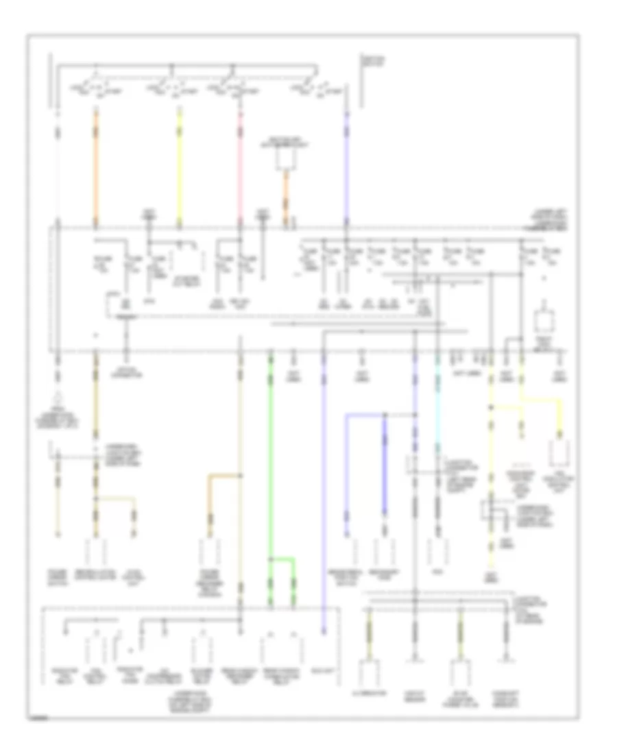 https://portal-diagnostov.com/license.html
Automotive Electricians Portal FZCO
Automotive Electricians Portal FZCO
https://portal-diagnostov.com/license.html
https://portal-diagnostov.com/license.html
Automotive Electricians Portal FZCO
Automotive Electricians Portal FZCOList of elements for Power Distribution Wiring Diagram (3 of 3) for Honda CR-V EX 2008:
- (ig1) fuel pump
- (not used)
- (under left side of dash) under-dash fuse/relay box
- A/c compressor clutch relay
- A17
- A22
- Acc
- Acc radio
- Alternator
- B17
- B22
- Blower motor relay
- Brake pedal position switch
- C36
- Camshaft position sensor a
- E10
- E13
- E24
- E27
- E28
- E30
- E32
- Eld unit
- Evap canister purge valve
- F15
- F16
- F17
- F24
- Fan control relay
- From under-hood fuse/relay box (diagram 1 of 3)
- Fuse (not used)
- Fuse 10a
- Fuse 15a
- Fuse 30a
- Fuse 7.5a
- G11
- G12
- G14
- G20
- Hvac control unit
- Ig1
- Ig1 (p/w)
- Ig1 abs
- Ig1 ods
- Ig1 srs
- Ig1 wiper
- Ig2 drl
- Ig2 hac
- Ignition key switch/key light
- Ignition switch
- Junction connector c101 (left rear of engine compt)
- Junction connector c103 (at rear of engine)
- Key sw acc
- Lock
- Maf/iat sensor
- Micu
- Moon roof control unit/ motor (ex)
- N11
- N12
- Option connector
- Pcm
- Pgm-fi main relay 2
- Power mirror defogger relay (canada)
- Power mirror switch
- Radiator fan diode
- Radiator fan relay
- Rear window defogger relay
- Rear window wiper motor relay
- Recirculation control motor
- Red
- Secondary ho2s
- Start
- Starter cut relay
- Sts
- Under-dash junction box (under left side of dash)
- Under-hood fuse/relay box (on left side of engine compt)
- Vsa modulator- control unit
POWER DOOR LOCKS
Power Door Locks Wiring Diagram (1 of 2) for Honda CR-V EX 2008
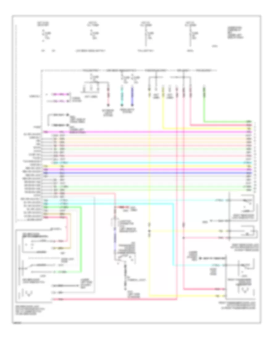 https://portal-diagnostov.com/license.html
Automotive Electricians Portal FZCO
Automotive Electricians Portal FZCO
https://portal-diagnostov.com/license.html
https://portal-diagnostov.com/license.html
Automotive Electricians Portal FZCO
Automotive Electricians Portal FZCOList of elements for Power Door Locks Wiring Diagram (1 of 2) for Honda CR-V EX 2008:
- (not used)
- (not used) c502
- (on transmission housing) transmission range switch
- (under left side of dash) g501
- (under middle of dash) g503
- +b d/l
- Atp-p
- B-can
- Door lock knob
- Dr lk rly
- Driver's door key cylinder switch
- Driver's door lock actuator/knob switch/ key cylinder switch (in driver's door)
- Driver's door lock knob switch
- Drv dr unlk rly
- E13
- E14
- E17
- E19
- E20
- E21
- E31
- E33
- E36
- E37
- Ex & ex-l
- Exterior lights system
- F20
- F23
- F27
- Fr dr sw (as)
- Fr dr sw (dr)
- Front passenger's door lock actuator/knob switch (in front passenger's door)
- Front passenger's door lock knob switch
- Fuse 10a
- Fuse 15a
- Fuse 20a
- Fuse 7.5a
- G101 (left side of engine)
- G13
- G16
- G17
- G401 (under left side of dash)
- G552
- G602 (left side of cargo area)
- Headlights system
- Hood sw
- Horn rly
- Horns system
- Hot at all times
- Hot in on or start
- Ig key sw
- Ig1
- Junction connector c101 (left rear of engine compt)
- Kc dr lock
- Kc dr unlock
- Key
- Lock
- Low beam headlight rly
- M10
- Micu
- N13
- P-gnd
- Pass dr unlk rly
- Pnk
- R16
- Red
- Red b1
- Rem as lock
- Rem as unlock
- Rem dr lock
- Rem dr unlock
- Right rear door lock actuator/knob switch (in right rear door)
- Right rear door lock knob switch
- Rr dr sw (as)
- Rr dr sw (dr)
- S3 (thermal joint)
- Sil as unlock
- Sil dr lock
- Sil dr unlock
- Sil ra unlock
- Sil rd unlock
- T/g handle sw
- T/g sw
- T/g unlk rly
- T22
- T23
- T24
- T25
- T26
- T27
- T28
- T29
- T30
- T31
- T32
- Taillight rly
- Under-dash fuse/relay box (under left side of dash)
- Unlock
- Vbu
Power Door Locks Wiring Diagram (2 of 2) for Honda CR-V EX 2008
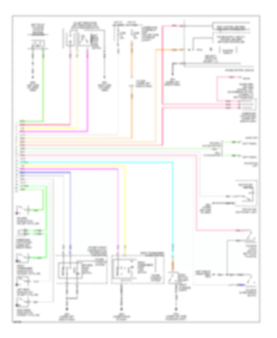 https://portal-diagnostov.com/license.html
Automotive Electricians Portal FZCO
Automotive Electricians Portal FZCO
https://portal-diagnostov.com/license.html
https://portal-diagnostov.com/license.html
Automotive Electricians Portal FZCO
Automotive Electricians Portal FZCOList of elements for Power Door Locks Wiring Diagram (2 of 2) for Honda CR-V EX 2008:
- (bottom of tailgate) tailgate release actuator
- (in left rear door) left rear door lock actuator/knob switch
- (left side of cargo area) g602
- Audio unit
- B-can
- Blinking circuit
- Body controller area network transceiver
- Driver's door lock switch
- Driver's door switch (on left "b" pillar)
- Ex & ex-l w/o navigation
- Ex-l w/ navigation
- Front passenger's door lock switch
- Front passenger's door switch (on right "b" pillar)
- Front passenger's window switch
- Fuse 10a
- Fuse 15a
- G301 (under left side of engine compt)
- G501 (under left side of dash)
- G503 (under middle of dash)
- G601 (right side of cargo area)
- G602 (left side of cargo area)
- Gauge control module
- Hood switch (except lx) (front of engine compt)
- Hot at all times
- Ignition key switch
- Ignition key switch/key light
- Immobilizer- keyless control unit (on steering column, integral to ignition switch)
- J/c c405 (under left side of dash)
- Left rear door switch (in left "c" pillar)
- Left unlock
- Lock
- Navigation unit
- Pnk
- Power window master switch/ driver's door lock switch
- Power windows system
- Rear door lock knob switch
- Right rear door switch (in right "c" pillar)
- Scty radio
- Security indicator (except: lx)
- Tailgate latch switch (bottom of tailgate)
- Tailgate outer handle switch
- Under-dash junction box (under left side of dash)
- Under-hood fuse/relay box (on left side of engine compt)
- Unlock
POWER MIRRORS
Power Mirrors Wiring Diagram, with Auto Dimming Inside Mirror for Honda CR-V EX 2008
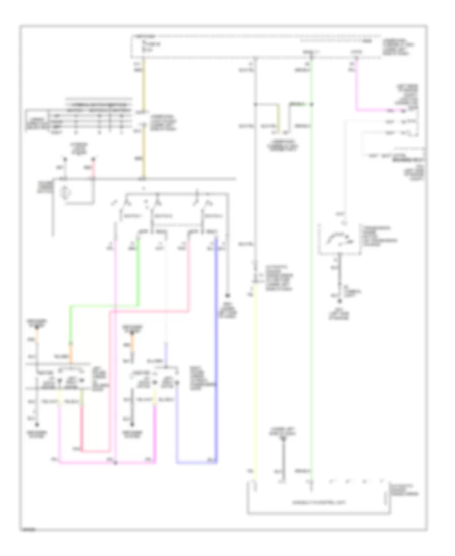 https://portal-diagnostov.com/license.html
Automotive Electricians Portal FZCO
Automotive Electricians Portal FZCO
https://portal-diagnostov.com/license.html
https://portal-diagnostov.com/license.html
Automotive Electricians Portal FZCO
Automotive Electricians Portal FZCOList of elements for Power Mirrors Wiring Diagram, with Auto Dimming Inside Mirror for Honda CR-V EX 2008:
- (atp-r) b14
- (has built-in control unit)
- (left rear of engine compt) junction connector c101
- (under left side of dash)
- (under left side of dash) g501
- 10a
- Atp-r
- Automatic dimming inside mirror
- Automatic dimming inside mirror in-line fuse
- Back lt
- Defogger system
- Down
- E13
- Fuse 36
- G101 (left side of engine)
- G501 (under left side of dash)
- Heater
- Hot in on
- Interior lights system
- Internal switch positions
- Left
- Left power mirror (in driver's door)
- Left/ right motor
- Micu
- Mirror direction selected
- N11
- Pcm (left side of engine compt)
- Pnk
- Power mirror switch
- Red
- Reverse input
- Right
- Right power mirror (in front passenger's door)
- S3 (thermal joint)
- Switch 1
- Switch 2
- Switch 3
- Transmission range switch (on transmission housing)
- Under-dash fuse/relay box (under left side of dash)
- Under-dash fuse/relay box connector a
- Under-dash junction box (under left side of dash)
- Up/ down motor
Power Mirrors Wiring Diagram, without Auto Dimming Inside Mirror for Honda CR-V EX 2008
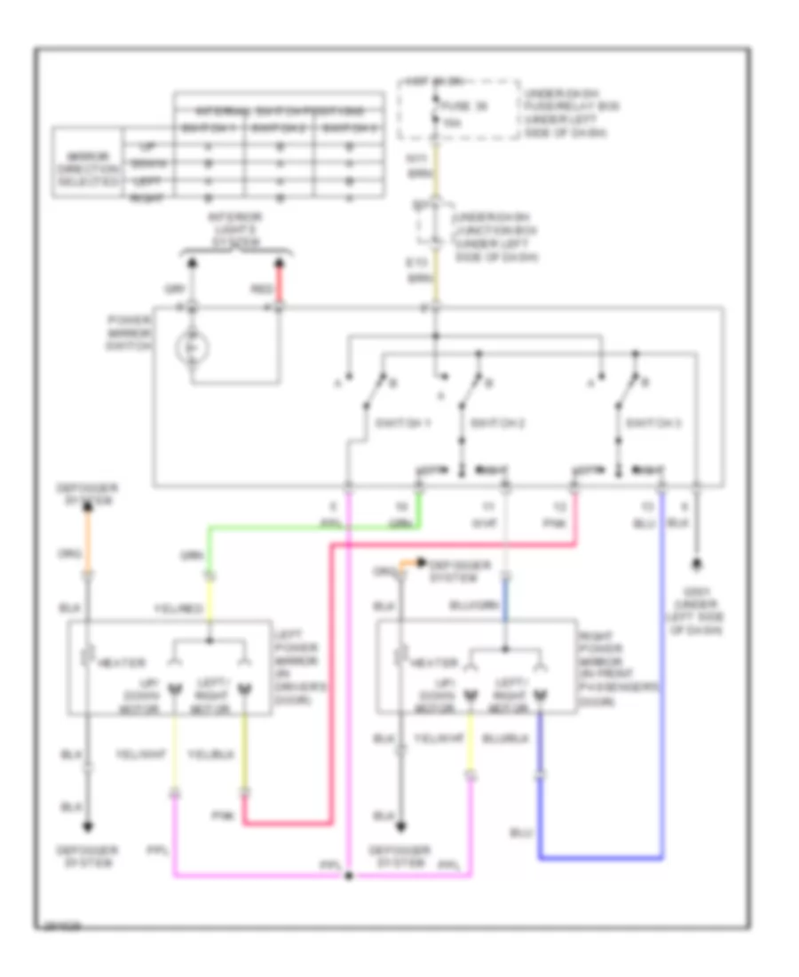 https://portal-diagnostov.com/license.html
Automotive Electricians Portal FZCO
Automotive Electricians Portal FZCO
https://portal-diagnostov.com/license.html
https://portal-diagnostov.com/license.html
Automotive Electricians Portal FZCO
Automotive Electricians Portal FZCOList of elements for Power Mirrors Wiring Diagram, without Auto Dimming Inside Mirror for Honda CR-V EX 2008:
- 10a
- Defogger system
- Door)
- Down
- E13
- Fuse 36
- G501 (under left side of dash)
- Heater
- Hot in on
- Interior lights system
- Internal switch positions
- Left
- Left power mirror (in driver's door)
- Left/ right motor
- Mirror direction selected
- N11
- Pnk
- Power mirror switch
- Red
- Right
- Right power mirror (in front passenger's
- Switch 1
- Switch 2
- Switch 3
- Under-dash fuse/relay box (under left side of dash)
- Under-dash junction box (under left side of dash)
- Up/ down motor
POWER SEATS
Driver Power Seat Wiring Diagram for Honda CR-V EX 2008
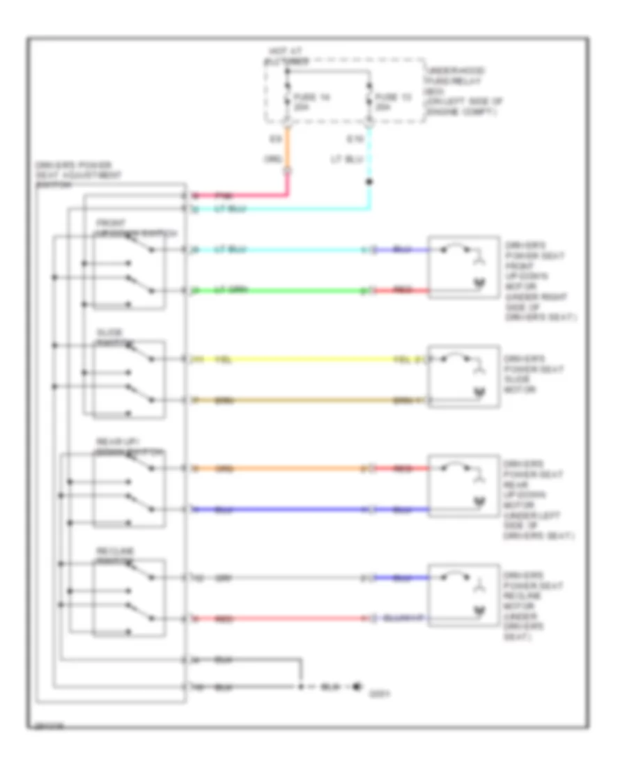 https://portal-diagnostov.com/license.html
Automotive Electricians Portal FZCO
Automotive Electricians Portal FZCO
https://portal-diagnostov.com/license.html
https://portal-diagnostov.com/license.html
Automotive Electricians Portal FZCO
Automotive Electricians Portal FZCOList of elements for Driver Power Seat Wiring Diagram for Honda CR-V EX 2008:
- Driver's power seat adjustment switch
- Driver's power seat front up-down motor (under right side of driver's seat)
- Driver's power seat rear up-down motor (under left side of driver's seat)
- Driver's power seat recline motor (under driver's seat)
- Driver's power seat slide motor
- E10
- Front up-down switch
- Fuse 13 20a
- Fuse 14 20a
- G551
- Hot at all times
- Pnk
- Rear up/ down switch
- Recline switch
- Red
- Slide switch
- Under-hood fuse/relay box (on left side of engine compt)
Driver"s Lumbar Wiring Diagram for Honda CR-V EX 2008
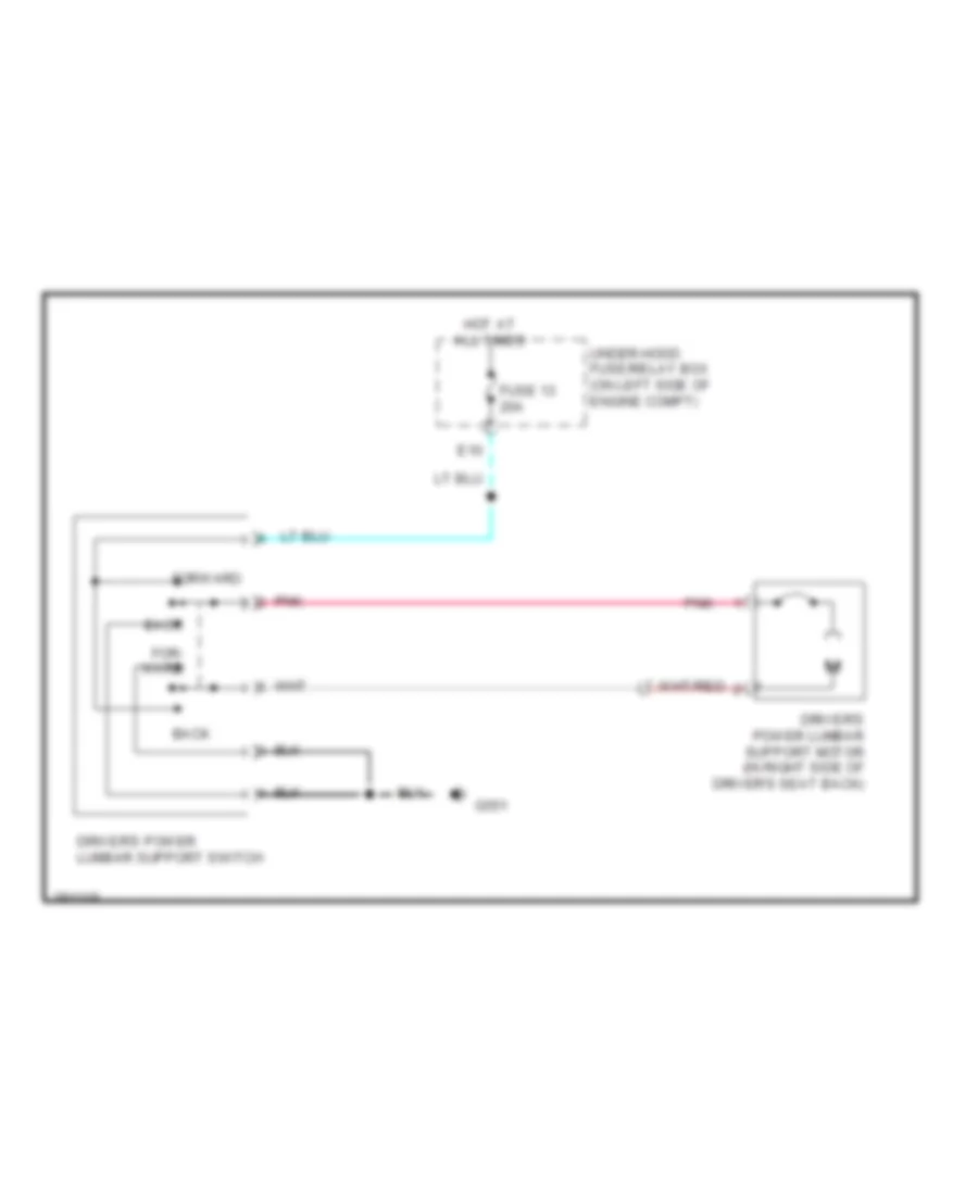 https://portal-diagnostov.com/license.html
Automotive Electricians Portal FZCO
Automotive Electricians Portal FZCO
https://portal-diagnostov.com/license.html
https://portal-diagnostov.com/license.html
Automotive Electricians Portal FZCO
Automotive Electricians Portal FZCOList of elements for Driver"s Lumbar Wiring Diagram for Honda CR-V EX 2008:
- Back
- Driver's power lumbar support motor (in right side of driver's seat back)
- Driver's power lumbar support switch
- E10
- For- ward
- Forward
- Fuse 13 20a
- G551
- Hot at all times
- Pnk
- Under-hood fuse/relay box (on left side of engine compt)
Heated Seats Wiring Diagram for Honda CR-V EX 2008
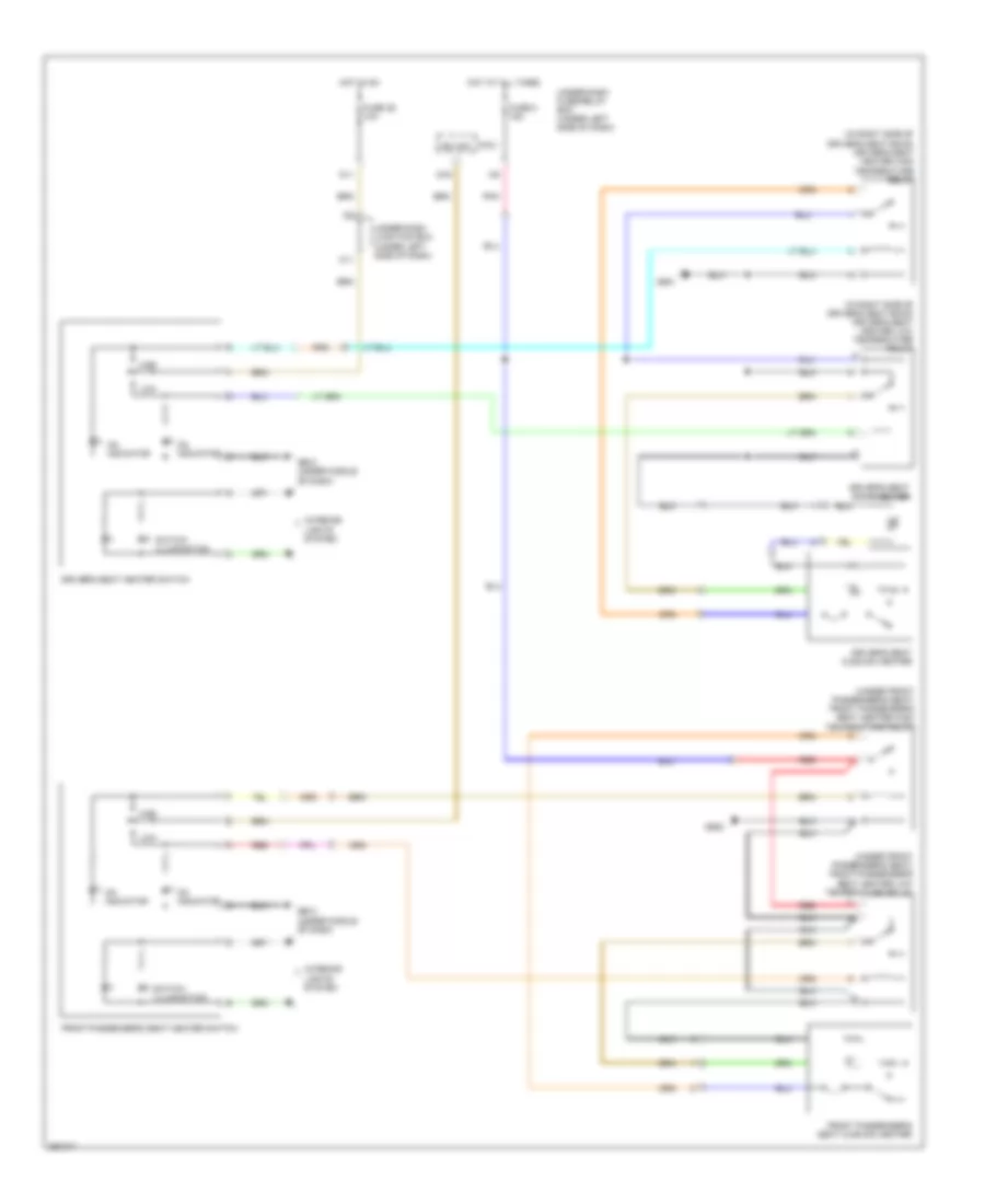 https://portal-diagnostov.com/license.html
Automotive Electricians Portal FZCO
Automotive Electricians Portal FZCO
https://portal-diagnostov.com/license.html
https://portal-diagnostov.com/license.html
Automotive Electricians Portal FZCO
Automotive Electricians Portal FZCOList of elements for Heated Seats Wiring Diagram for Honda CR-V EX 2008:
- (in right side of driver's seat back) driver's seat heater high temperature relay
- (in right side of driver's seat back) driver's seat heater low temperature relay
- (under front passenger's seat) front passenger's seat heater high temperature relay
- (under front passenger's seat) front passenger's seat heater low temperature relay
- Driver's seat back heater
- Driver's seat cushion heater
- Driver's seat heater switch
- Front passenger's seat cushion heater
- Front passenger's seat heater switch
- Fuse 36 10a
- Fuse 5 15a
- G502 (under middle of dash)
- G503 (under middle of dash)
- G551
- G552
- High
- Hot at all times
- Hot in on
- Ig2 hac
- Interior lights system
- K11
- Low
- Micu
- N11
- On indicator
- Pnk
- Q16
- Red
- Switch illumination
- Under-dash fuse/relay box (under left side of dash)
- Under-dash junction box (under left side of dash)
POWER TOP/SUNROOF
Power Top/Sunroof Wiring Diagram for Honda CR-V EX 2008
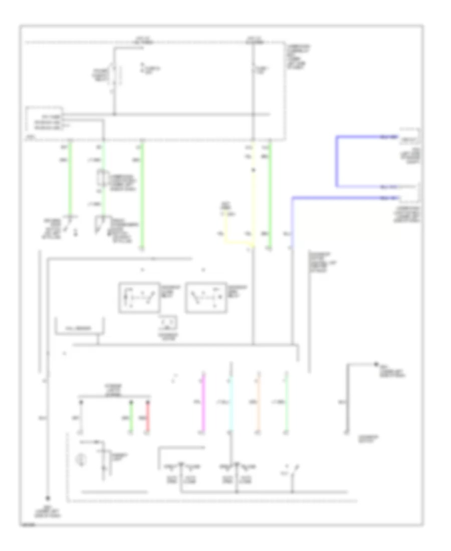 https://portal-diagnostov.com/license.html
Automotive Electricians Portal FZCO
Automotive Electricians Portal FZCO
https://portal-diagnostov.com/license.html
https://portal-diagnostov.com/license.html
Automotive Electricians Portal FZCO
Automotive Electricians Portal FZCOList of elements for Power Top/Sunroof Wiring Diagram for Honda CR-V EX 2008:
- (not used)
- A29
- Ambient light
- Auto close
- Auto open
- C801
- Close
- Driver's door switch (on left "b" pillar)
- E37
- Fr dr sw (as)
- Fr dr sw (dr)
- Front passenger's door switch (on right "b" pillar)
- Fuse 1 7.5a
- Fuse 24 20a
- G13
- G501 (under left side of dash)
- Hall sensor
- Hot at all times
- Interior lights system
- Micu
- Moonroof close relay
- Moonroof motor
- Moonroof motor/ control unit (center of roof)
- Moonroof open relay
- Moonroof switch
- N10
- N12
- Off
- Open
- Pcm (left side of engine compt)
- Power window relay
- Pw timer
- Red
- Tilt
- Under-dash fuse/relay box (under left side of dash)
- Under-dash junction box (under left side of dash)
- Vss out
POWER WINDOWS
Power Windows Wiring Diagram for Honda CR-V EX 2008
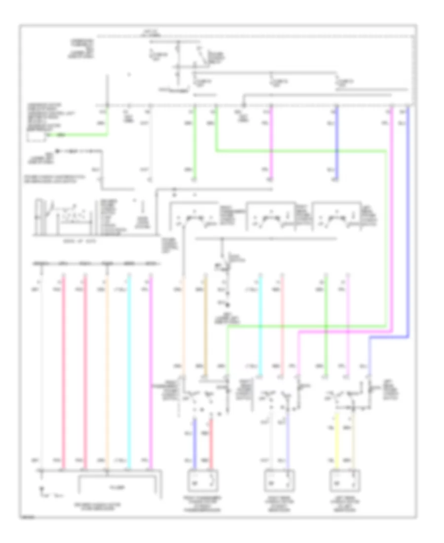 https://portal-diagnostov.com/license.html
Automotive Electricians Portal FZCO
Automotive Electricians Portal FZCO
https://portal-diagnostov.com/license.html
https://portal-diagnostov.com/license.html
Automotive Electricians Portal FZCO
Automotive Electricians Portal FZCOList of elements for Power Windows Wiring Diagram for Honda CR-V EX 2008:
- (moonroof motor: middle of roof) (moonroof control unit: center of roof) (ex & ex-l) moonroof motor/ control unit
- (not used)
- Auto
- Door locks system
- Down
- Down(+)
- Driver's power window switch 0) off 1) up 2) down 3) auto down 4) auto up
- Driver's window motor (in driver's door)
- E23
- E41
- Front passenger's power window switch
- Front passenger's window motor (in front passenger's door)
- Fuse 26 20a
- Fuse 30 20a
- Fuse 32 20a
- Fuse 33 20a
- G501 (under left side of dash)
- Hot at all times
- Left rear power
- Left rear power window switch
- Left rear window motor (in left rear door)
- Main switch
- Micu
- N10
- N14
- Off
- Pls a
- Pls b
- Pnk
- Power window control unit
- Power window master switch/ driver's door lock switch
- Power window relay
- Pulser
- Pw timer
- Red
- Right rear power window switch
- Right rear window motor (in right rear door)
- Sgnd
- Svcc
- Under-dash fuse/relay box (under left side of dash)
- Up(+)
- Window switch
RADIO
Bass Speaker Wiring Diagram, Accessory, LX, EX & EX-L without Navigation for Honda CR-V EX 2008
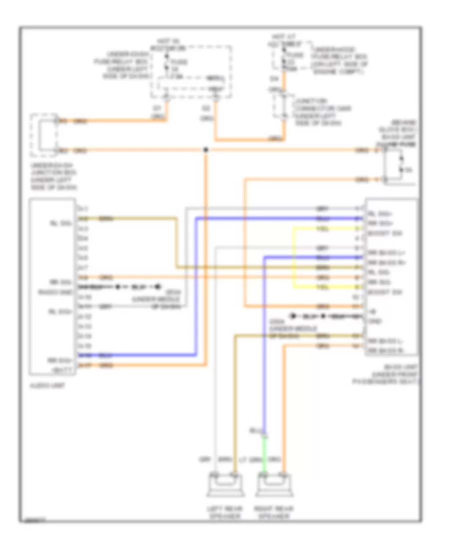 https://portal-diagnostov.com/license.html
Automotive Electricians Portal FZCO
Automotive Electricians Portal FZCO
https://portal-diagnostov.com/license.html
https://portal-diagnostov.com/license.html
Automotive Electricians Portal FZCO
Automotive Electricians Portal FZCOList of elements for Bass Speaker Wiring Diagram, Accessory, LX, EX & EX-L without Navigation for Honda CR-V EX 2008:
- (behind glove box) bass unit in-line fuse
- +batt
- A10
- A11
- A12
- A13
- A14
- A15
- A16
- A17
- Audio unit
- Bass unit (under front passenger's seat)
- Boost sw
- Fuse 10a
- Fuse 7.5a
- G504 (under middle of dash)
- Gnd
- Hot at all times
- Hot in acc or on
- Junction connector c405 (under left side of dash)
- Left rear speaker
- Micu
- Radio gnd
- Right rear speaker
- Rl sig+
- Rl sig-
- Rr bass l+
- Rr bass l-
- Rr bass r+
- Rr bass r-
- Rr sig+
- Rr sig-
- Under-dash fuse/relay box (under left side of dash)
- Under-dash junction box (under left side of dash)
- Under-hood fuse/relay box (on left side of engine compt)
- Vbu
Music Link Wiring Diagram, Accessory, LX, EX & EX-L without Navigation for Honda CR-V EX 2008
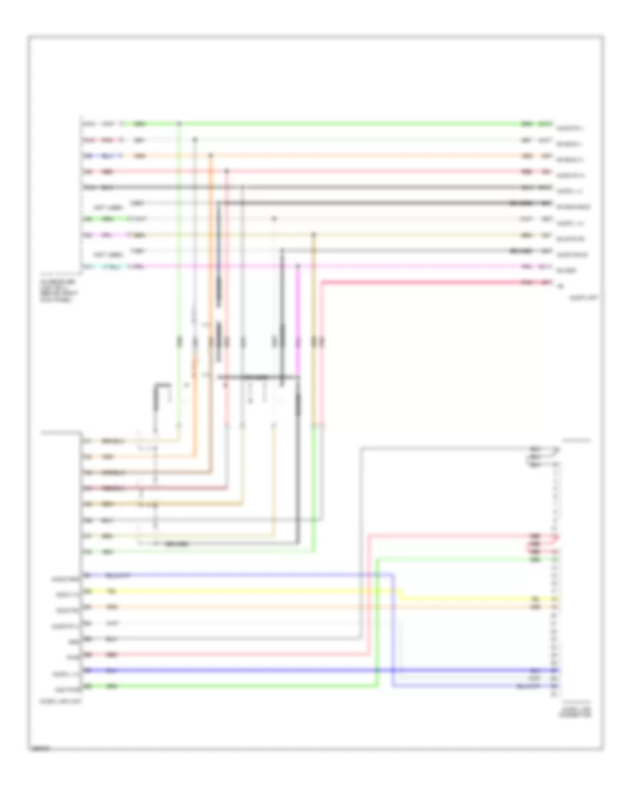 https://portal-diagnostov.com/license.html
Automotive Electricians Portal FZCO
Automotive Electricians Portal FZCO
https://portal-diagnostov.com/license.html
https://portal-diagnostov.com/license.html
Automotive Electricians Portal FZCO
Automotive Electricians Portal FZCOList of elements for Music Link Wiring Diagram, Accessory, LX, EX & EX-L without Navigation for Honda CR-V EX 2008:
- (not used)
- A10
- A11
- A13
- A14
- Acc pwr
- Audio gnd
- Audio l (+)
- Audio l (-)
- Audio r (+)
- Audio r (-)
- Audio shld
- Audio unit
- Braided
- D10
- D11
- D13
- D14
- Dock rx
- Docx tx
- Ga bus (+)
- Ga bus (-)
- Ga bus shld
- Ga gnd
- Ga sys on
- Gnd
- Music link connector
- Music link unit
- Pnk
- Pwr
- Red
- Xm receiver (usa: ex-l) (behind right kick panel)
Music Link Wiring Diagram, EX-L with Navigation for Honda CR-V EX 2008
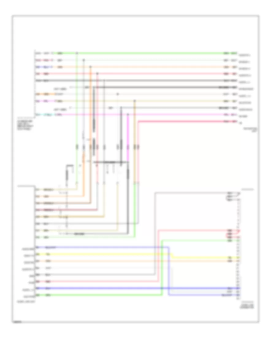 https://portal-diagnostov.com/license.html
Automotive Electricians Portal FZCO
Automotive Electricians Portal FZCO
https://portal-diagnostov.com/license.html
https://portal-diagnostov.com/license.html
Automotive Electricians Portal FZCO
Automotive Electricians Portal FZCOList of elements for Music Link Wiring Diagram, EX-L with Navigation for Honda CR-V EX 2008:
- (not used)
- A10
- A11
- A13
- A14
- Acc pwr
- Audio gnd
- Audio l (+)
- Audio l (-)
- Audio r (+)
- Audio r (-)
- Audio shld
- Braided
- Dock rx
- Docx tx
- E10
- E11
- E13
- E14
- Ga bus (+)
- Ga bus (-)
- Ga bus shld
- Ga gnd
- Ga sys on
- Gnd
- Music link connector
- Music link unit
- Navigation unit
- Pnk
- Pwr
- Red
- Xm receiver (usa: ex-l) (behind right kick panel)
Radio Wiring Diagram, EX, EX-L without Navigation (1 of 2) for Honda CR-V EX 2008
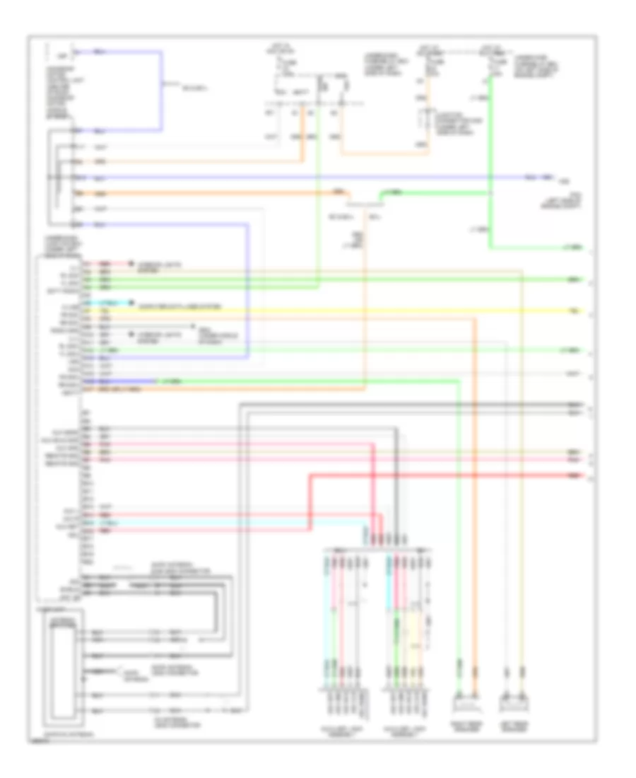 https://portal-diagnostov.com/license.html
Automotive Electricians Portal FZCO
Automotive Electricians Portal FZCO
https://portal-diagnostov.com/license.html
https://portal-diagnostov.com/license.html
Automotive Electricians Portal FZCO
Automotive Electricians Portal FZCOList of elements for Radio Wiring Diagram, EX, EX-L without Navigation (1 of 2) for Honda CR-V EX 2008:
- +batt
- A10
- A11
- A12
- A13
- A14
- A15
- A16
- A17
- A29
- Acc
- Adu
- Am/fm antenna
- Am/fm antenna lead connector
- Am/fm antenna sub-lead connector
- Am/fm/xm antenna
- Ant +b
- Antenna amplifier
- Audio unit
- Aux det
- Aux gnd
- Aux l
- Aux lch
- Aux r
- Aux rch
- Aux sgnd
- Aux shld gnd
- Auxiliary jack assembly
- B10
- B11
- B12
- B13
- B14
- B15
- B16
- B17
- B18
- B19
- B20
- Computer data lines system
- Ex & ex-l
- Ex-l
- Fl sig+
- Fl sig-
- Fr sig+
- Fr sig-
- Fuse 10a
- Fuse 15a
- Fuse 7.5a
- G13
- G504 (under middle of dash)
- Hot at all times
- Hot in acc or on
- Ill+
- Ill-
- Interior lights system
- Junction connector c405 (under left side of dash)
- K-line
- L11
- Left rear speaker
- Micu
- Moonroof motor/ control unit (center of roof) moonroof motor/ (middle of roof)
- Nca
- Pcm (left side of engine compt)
- Pnk
- R17
- Radio gnd
- Radio sw
- Red
- Remote gnd
- Right rear speaker
- Rl sig+
- Rl sig-
- Rr sig+
- Rr sig-
- Scty radio
- Shield
- Sig
- Under-dash fuse/relay box (under left side of dash)
- Under-dash junction box (under left side of dash)
- Under-hood fuse/relay box (on left side of engine compt)
- Vbu
- Vsp
- Vss
- Xm antenna lead connector
Radio Wiring Diagram, EX, EX-L without Navigation (2 of 2) for Honda CR-V EX 2008
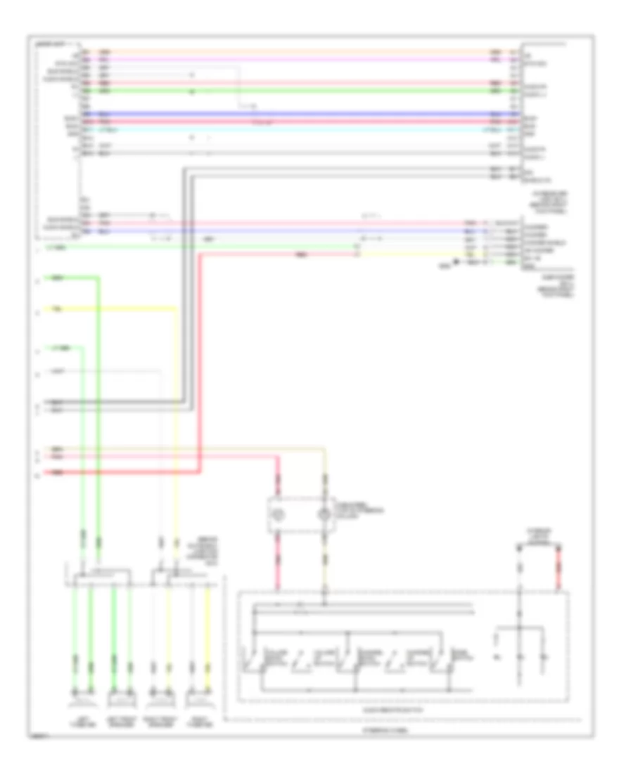 https://portal-diagnostov.com/license.html
Automotive Electricians Portal FZCO
Automotive Electricians Portal FZCO
https://portal-diagnostov.com/license.html
https://portal-diagnostov.com/license.html
Automotive Electricians Portal FZCO
Automotive Electricians Portal FZCOList of elements for Radio Wiring Diagram, EX, EX-L without Navigation (2 of 2) for Honda CR-V EX 2008:
- (behind glove box) junction connector c510
- +b woofer
- A10
- A11
- A12
- A13
- A14
- Audio l+
- Audio l-
- Audio r+
- Audio r-
- Audio remote switch
- Audio shield
- Audio unit
- Bus shield
- Bus+
- Bus-
- C10
- Cable reel (top of steering column)
- Channel down switch
- Channel up switch
- E10
- E11
- E12
- E13
- E14
- G552
- Gnd
- Interior lights system
- Left front speaker
- Left tweeter
- Mode switch
- Nca
- Pnk
- Red
- Right front speaker
- Right tweeter
- Shield xm
- Sig
- Steering wheel
- Subwoofer (ex-l) (behind right kick panel)
- Sw +b
- Sys acc
- Volume down switch
- Volume up switch
- Woofer shield
- Woofer+
- Woofer-
- Xm receiver (usa: ex-l) (behind right kick panel)
Radio Wiring Diagram, LX for Honda CR-V EX 2008
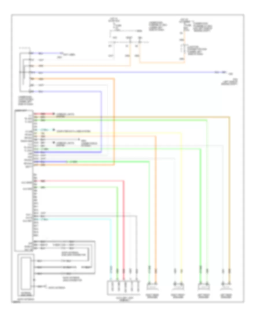 https://portal-diagnostov.com/license.html
Automotive Electricians Portal FZCO
Automotive Electricians Portal FZCO
https://portal-diagnostov.com/license.html
https://portal-diagnostov.com/license.html
Automotive Electricians Portal FZCO
Automotive Electricians Portal FZCOList of elements for Radio Wiring Diagram, LX for Honda CR-V EX 2008:
- (not used)
- +batt
- A10
- A11
- A12
- A13
- A14
- A15
- A16
- A17
- A29
- Acc
- Am/fm antenna
- Am/fm antenna lead connector
- Am/fm antenna sub-lead connector
- Ant +b
- Antenna amplifier
- Audio unit
- Aux det
- Aux gnd
- Aux l
- Aux l ch
- Aux r
- Aux r ch
- Aux sgnd
- Auxiliary jack assembly
- B10
- B11
- B12
- B13
- B14
- B15
- B16
- B17
- B18
- B19
- B20
- C801
- Computer data lines system
- Fl sig+
- Fl sig-
- Fr sig+
- Fr sig-
- Fuse 10a
- Fuse 7.5a
- G13
- G504 (under middle of dash)
- Hot at all times
- Hot in on or acc
- Ill+
- Ill-
- Interior lights system
- Junction connector c405 (under left side of dash)
- K-line
- Left front speaker
- Left rear speaker
- Micu
- Nca
- Pcm (left side of engine compt)
- R17
- Radio gnd
- Red
- Right front speaker
- Right rear speaker
- Rl sig+
- Rl sig-
- Rr sig+
- Rr sig-
- Shield
- Sig
- Under-dash fuse/relay box (under left side of dash)
- Under-dash junction box (under left side of dash)
- Under-hood fuse/relay box (on left side of engine compt)
- Vbu
- Vsp
- Vss
SHIFT INTERLOCK
Shift Interlock Wiring Diagram for Honda CR-V EX 2008
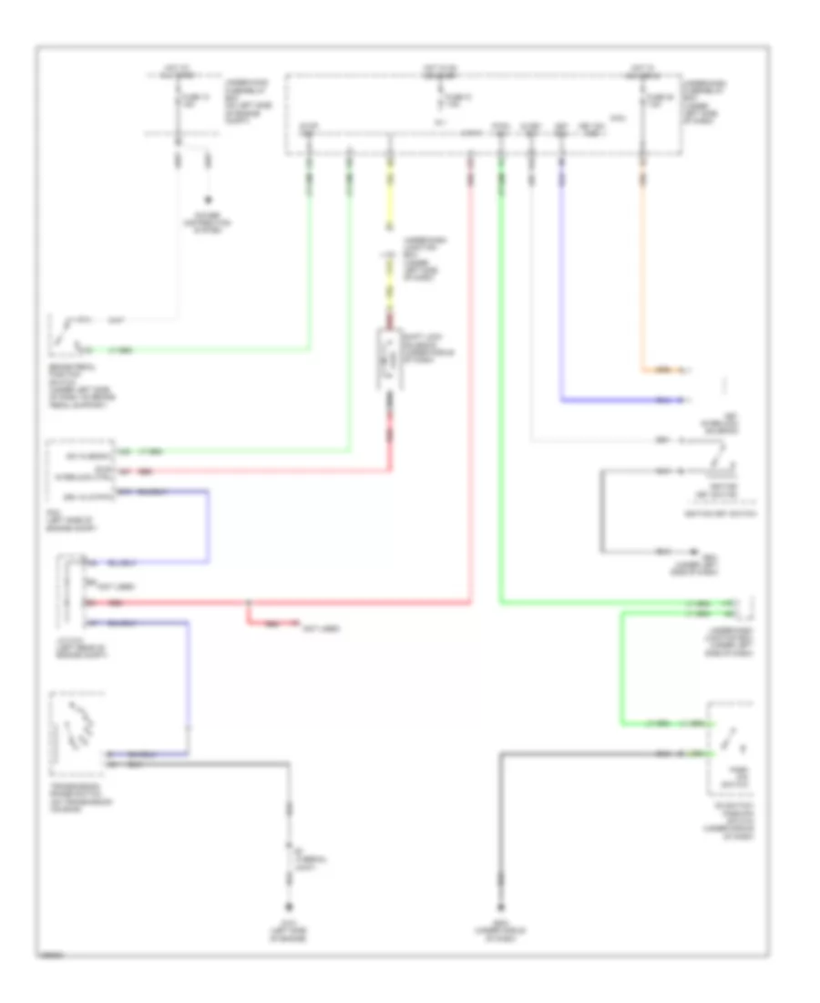 https://portal-diagnostov.com/license.html
Automotive Electricians Portal FZCO
Automotive Electricians Portal FZCO
https://portal-diagnostov.com/license.html
https://portal-diagnostov.com/license.html
Automotive Electricians Portal FZCO
Automotive Electricians Portal FZCOList of elements for Shift Interlock Wiring Diagram for Honda CR-V EX 2008:
- (not used)
- (sls) a27
- (thermal
- A40
- Atp-p
- B13
- Brake pedal position switch (under left side of dash, on brake pedal support)
- C13
- D3 switch/ park-pin switch (under middle of dash)
- Drv in (atp-p)
- F25
- F27
- F30
- Fuse 10 7.5a
- Fuse 12 15a
- Fuse 35 7.5a
- G101 (left side of engine)
- G501 (under left side of dash)
- G503 (under middle of dash)
- Hot at all times
- Hot in acc or on
- Hot in on or start
- Ig 1
- Ig key sw
- Ignition key switch
- Interlock ctrl
- J/c c101 (left rear of engine compt)
- J18
- Joint)
- Key interlock solenoid
- Key sol
- Key sw acc
- Micu
- P-pin sw
- Park pin switch
- Pcm (left side of engine compt)
- Power distribution system
- R16
- Red
- Shift lock solenoid (under middle of dash)
- Stop sw
- Sw in (bksw)
- Transmission range switch (on transmission housing)
- Under-dash fuse/relay box (under left side of dash)
- Under-dash junction box (under left side of dash)
- Under-hood fuse/relay box (on left side of engine compt)
STARTING/CHARGING
Charging Wiring Diagram for Honda CR-V EX 2008
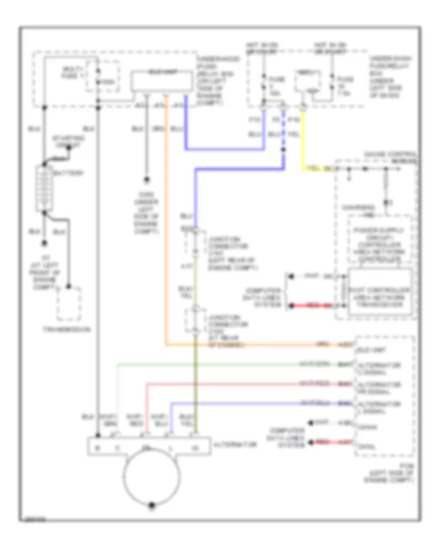 https://portal-diagnostov.com/license.html
Automotive Electricians Portal FZCO
Automotive Electricians Portal FZCO
https://portal-diagnostov.com/license.html
https://portal-diagnostov.com/license.html
Automotive Electricians Portal FZCO
Automotive Electricians Portal FZCOList of elements for Charging Wiring Diagram for Honda CR-V EX 2008:
- 100a
- A17
- A23
- A37
- A38
- Alternator
- B22
- B41 alternator c signal
- B42 alternator l signal
- B43 alternator fr signal
- Battery
- Can-h
- Can-l
- Charging ind
- Computer data lines system
- Eld unit
- F15
- Fast controller area network transceiver
- Fuse 10a
- Fuse 7.5a
- G1 (at left front of engine compt)
- G302 (under left side of engine compt)
- Gauge control module
- Hot in on or start
- Ig1
- Junction connector c101 (left rear of engine compt)
- Junction connector c103 (at rear of engine)
- Micu
- Multi- fuse 1
- P10
- Pcm (left side of engine compt)
- Red
- Starting circuit
- Transmission
- Under-dash fuse/relay box (under left side of dash)
- Under-hood fuse/ relay box (on left side of engine compt)
Remote Starting Wiring Diagram (1 of 2) for Honda CR-V EX 2008
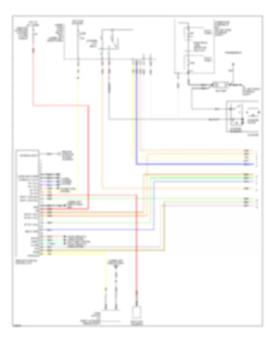 https://portal-diagnostov.com/license.html
Automotive Electricians Portal FZCO
Automotive Electricians Portal FZCO
https://portal-diagnostov.com/license.html
https://portal-diagnostov.com/license.html
Automotive Electricians Portal FZCO
Automotive Electricians Portal FZCOList of elements for Remote Starting Wiring Diagram (1 of 2) for Honda CR-V EX 2008:
- (under left side of dash) g501
- 100a
- 50a
- Antenna input
- B-can
- Battery
- Combi gnd wiper
- Computer data lines system anti-theft system computer data lines system
- Electrical load detector (eld) unit
- F29
- Fuse 7.5a
- G1 (at left front of engine compt)
- G20
- Gnd
- Hood sw
- Hood switch (lx) (front of engine engine compt)
- Hot at all times
- Hot in on or start
- Ig1
- Ig1 p/w
- Ig1 rly coil
- Ig2 rly coil
- Int vol+
- K-line
- Multi- fuse 1
- Multi- fuse 2
- N12
- Nca
- Pnk
- Power tops system
- Red
- Relay gnd
- Remote starting control unit
- Remote starting system antenna
- Remote starting system in-line fuse b
- S-net
- Scs
- Shift lock sol
- Shiftlock solenoid
- St rly coil
- Starter
- Starter cut relay
- Starter motor
- Starter solenoid
- Transmission
- Under- dash fuse/ relay box (under left side of dash)
- Under-hood fuse/relay box (on left side of engine compt)
- Wiper cut (out)
- Wiper/ washer system
Remote Starting Wiring Diagram (2 of 2) for Honda CR-V EX 2008
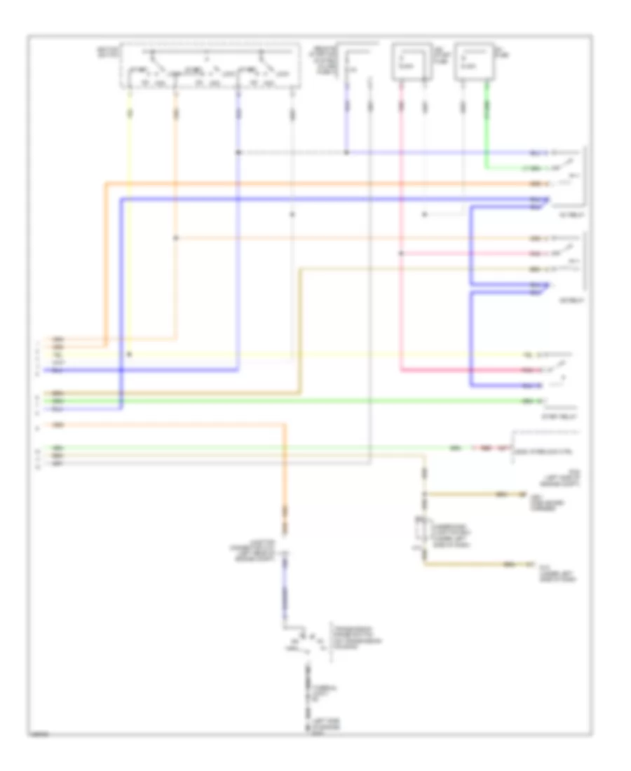 https://portal-diagnostov.com/license.html
Automotive Electricians Portal FZCO
Automotive Electricians Portal FZCO
https://portal-diagnostov.com/license.html
https://portal-diagnostov.com/license.html
Automotive Electricians Portal FZCO
Automotive Electricians Portal FZCOList of elements for Remote Starting Wiring Diagram (2 of 2) for Honda CR-V EX 2008:
- (left side of engine) g101
- (scs) interlock ctrl
- (thermal joint) s3
- (under left side of dash)
- 40a
- A20
- A27
- Acc
- B19
- C501 dash board harness
- Dlc (under left side of dash)
- Ig1 fuse
- Ig1 relay
- Ig2 relay
- Ig2/ start fuse
- Ignition switch
- Junction connector c101 (left rear of engine compt)
- Lock
- Pcm (left side of engine compt)
- Pnk
- Red
- Remote starting system in-line fuse a
- Start
- Start relay
- Transmission range switch (on transmission housing)
- Under-dash junction box
Starting Wiring Diagram for Honda CR-V EX 2008
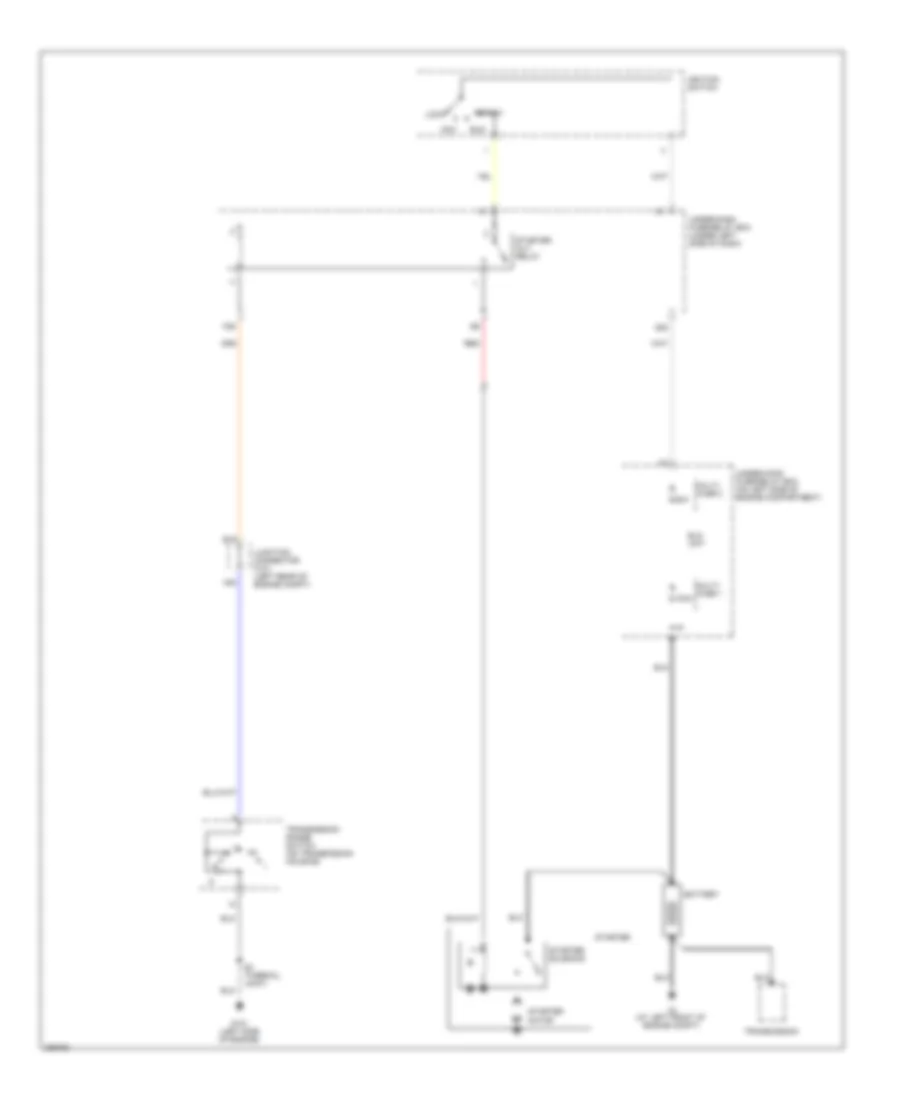 https://portal-diagnostov.com/license.html
Automotive Electricians Portal FZCO
Automotive Electricians Portal FZCO
https://portal-diagnostov.com/license.html
https://portal-diagnostov.com/license.html
Automotive Electricians Portal FZCO
Automotive Electricians Portal FZCOList of elements for Starting Wiring Diagram for Honda CR-V EX 2008:
- 100a
- 50a
- A20
- Acc
- B19
- Battery
- Eld unit
- F29
- G1 (at left front of engine compt)
- G101 (left side of engine)
- G20
- Ignition switch
- Junction connector c101 (left rear of engine compt)
- Lock
- Multi- fuse 1
- Multi- fuse 2
- Red
- Run
- S3 (thermal joint)
- Start
- Starter
- Starter cut relay
- Starter motor
- Starter solenoid
- Transmission
- Transmission range switch (on transmission housing)
- Under-dash fuse/relay box (under left side of dash)
- Under-hood fuse/relay box (on left side of engine compartment)
SUPPLEMENTAL RESTRAINTS
Supplemental Restraints Wiring Diagram (1 of 4) for Honda CR-V EX 2008
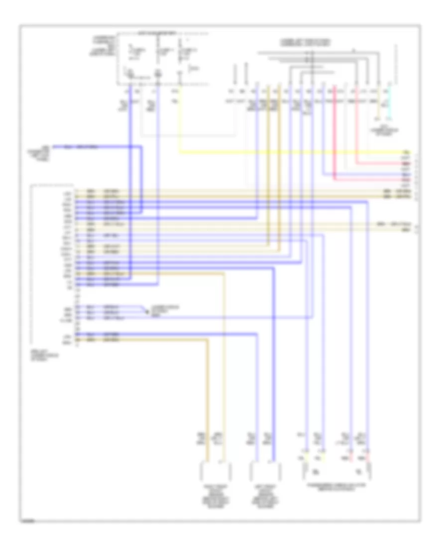 https://portal-diagnostov.com/license.html
Automotive Electricians Portal FZCO
Automotive Electricians Portal FZCO
https://portal-diagnostov.com/license.html
https://portal-diagnostov.com/license.html
Automotive Electricians Portal FZCO
Automotive Electricians Portal FZCOList of elements for Supplemental Restraints Wiring Diagram (1 of 4) for Honda CR-V EX 2008:
- (or pnk)
- (or red)
- (under left side of dash) underdash junction box
- (under middle of dash) g505
- C14
- Can-h
- Can-l
- Dlc (under middle of dash)
- Fuse 10 7.5a
- Fuse 11 10a
- Fuse 9 7.5a
- Grd
- H10
- Hot in on or start
- Ig1
- Ig1 ods
- Ig1 srs
- J13
- K-line
- La1+
- La1-
- La2+
- La2-
- Left front impact sensor (behind left side of front bumper)
- Lfs+
- Lfs-
- Mes
- Mes connector (left kick panel)
- Micu
- Ods
- P10
- Passenger's airbag inflator (behind glove box)
- Pnk
- Ptt
- Ra1+
- Ra1-
- Ra2+
- Ra2-
- Red
- Rfs+
- Rfs-
- Right front impact sensor (behind right side of front bumper)
- Scs
- Srs unit (under middle of dash)
- Underdash fuse/relay box (under left side of dash)
Supplemental Restraints Wiring Diagram (2 of 4) for Honda CR-V EX 2008
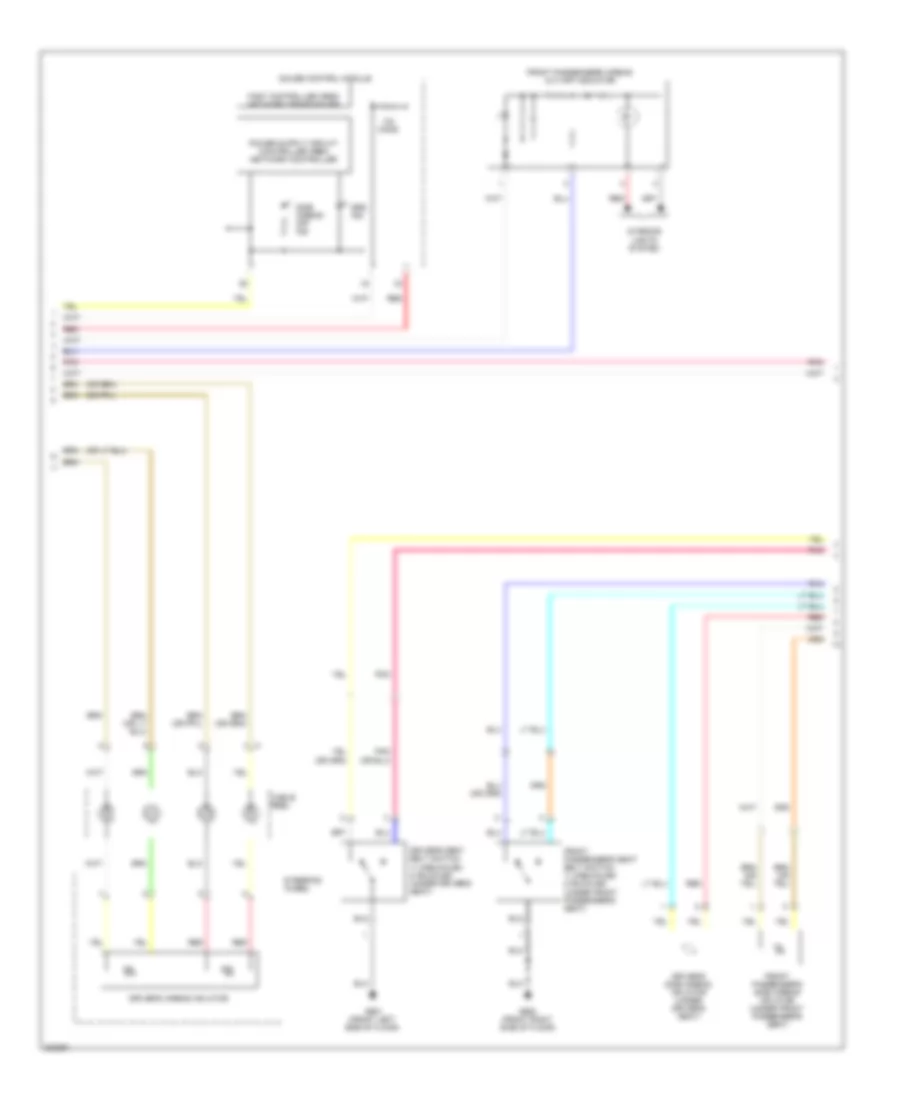 https://portal-diagnostov.com/license.html
Automotive Electricians Portal FZCO
Automotive Electricians Portal FZCO
https://portal-diagnostov.com/license.html
https://portal-diagnostov.com/license.html
Automotive Electricians Portal FZCO
Automotive Electricians Portal FZCOList of elements for Supplemental Restraints Wiring Diagram (2 of 4) for Honda CR-V EX 2008:
- Cable reel
- Driver's airbag inflator
- Driver's seat belt switch 1) unbuckled 2) buckled (under driver's seat)
- Driver's side airbag inflator (under driver's seat)
- Fast controller area network transceiver
- Front passenger's airbag cut-off indicator
- Front passenger's seat belt switch 1) unbuckled 2) buckled (under front passenger's seat)
- Front passenger's side airbag inflator (under front passenger's seat)
- G651 (front left side of floor)
- G652 (front right side of floor)
- Gauge control module
- Interior lights system
- Ohms
- Pnk
- Red
- Side airbag off ind
- Srs ind
- Steering wheel
Supplemental Restraints Wiring Diagram (3 of 4) for Honda CR-V EX 2008
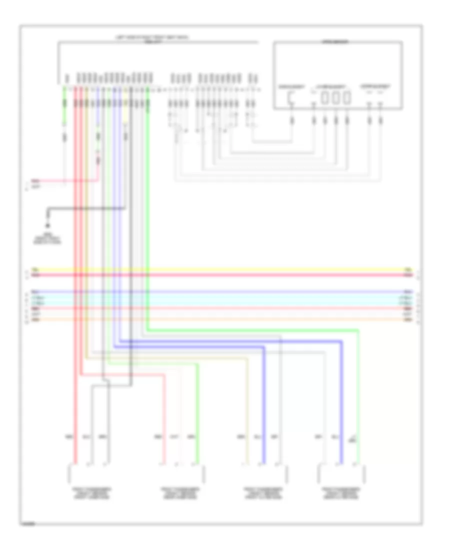 https://portal-diagnostov.com/license.html
Automotive Electricians Portal FZCO
Automotive Electricians Portal FZCO
https://portal-diagnostov.com/license.html
https://portal-diagnostov.com/license.html
Automotive Electricians Portal FZCO
Automotive Electricians Portal FZCOList of elements for Supplemental Restraints Wiring Diagram (3 of 4) for Honda CR-V EX 2008:
- (left side of right front seat back) ods unit
- Front passenger's weight sensor (front inner side)
- Front passenger's weight sensor (front outer side)
- Front passenger's weight sensor (rear inner side)
- Front passenger's weight sensor (rear outer side)
- G652 (front right side of floor)
- Grd
- Lower element
- Ods
- Opds sensor
- Os1l
- Os1s
- Os2l
- Os2s
- Os3l
- Os3s
- Os4l
- Os4s
- Os5l
- Os5s
- Os6l
- Os6s
- Os7l
- Os7s
- Pnk
- Pow
- Red
- Side element
- Upper element
- Ws1d
- Ws1g
- Ws1p
- Ws2d
- Ws2g
- Ws2p
- Ws3d
- Ws3g
- Ws3p
- Ws4d
- Ws4g
- Ws4p
Supplemental Restraints Wiring Diagram (4 of 4) for Honda CR-V EX 2008
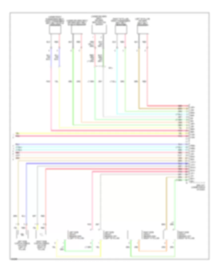 https://portal-diagnostov.com/license.html
Automotive Electricians Portal FZCO
Automotive Electricians Portal FZCO
https://portal-diagnostov.com/license.html
https://portal-diagnostov.com/license.html
Automotive Electricians Portal FZCO
Automotive Electricians Portal FZCOList of elements for Supplemental Restraints Wiring Diagram (4 of 4) for Honda CR-V EX 2008:
- (left "b" pillar) driver's seat belt tensioner
- (right "b" pillar) front passenger's seat belt tensioner
- (under driver's seat) driver's seat belt buckle tensioner
- (under driver's seat) driver's seat position sensor
- (under front passenger's seat) front passenger's seat belt buckle tensioner
- Ex-l
- Flbc
- Flbo
- Frbc
- Frbo
- Lbp+
- Lbp-
- Lca1+
- Lca1-
- Left side curtain airbag inflator (left "d" pillar)
- Left side impact sensor (1st) (left "b" pillar)
- Left side impact sensor (2nd) (left "c" pillar)
- Lrp+
- Lrp-
- Ls1+
- Ls1-
- Lsa+
- Lsa-
- Pnk
- Rbp+
- Rbp-
- Rca1+
- Rca1-
- Red
- Right side curtain airbag inflator (right "d" pillar)
- Right side impact sensor (1st) (right "b" pillar)
- Right side impact sensor (2nd) (right "c" pillar)
- Rrp+
- Rrp-
- Rs1+
- Rs1-
- Rsa+
- Rsa-
- Srs unit (under middle of dash)
- Ss+
- Ss-
TRANSMISSION
Transmission Wiring Diagram (1 of 2) for Honda CR-V EX 2008
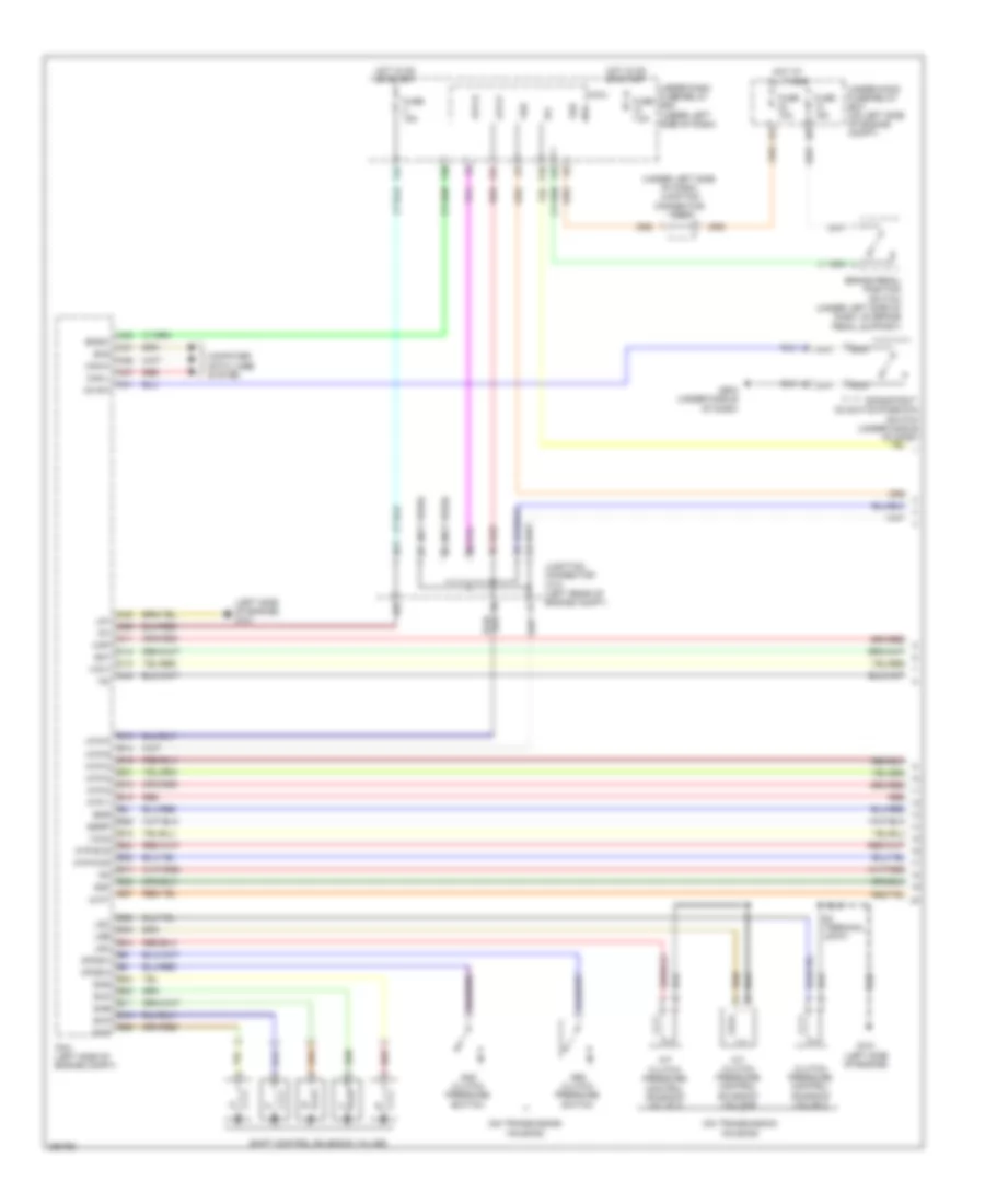 https://portal-diagnostov.com/license.html
Automotive Electricians Portal FZCO
Automotive Electricians Portal FZCO
https://portal-diagnostov.com/license.html
https://portal-diagnostov.com/license.html
Automotive Electricians Portal FZCO
Automotive Electricians Portal FZCOList of elements for Transmission Wiring Diagram (1 of 2) for Honda CR-V EX 2008:
- (left side of engine) g101
- (not used)
- (on transmission housing)
- (under left side of dash) junction connector c405
- 2nd clutch pressure switch
- 3rd clutch pressure switch
- A/t clutch pressure control solenoid valve a
- A/t clutch pressure control solenoid valve b
- A22
- A31
- A36
- A37
- A40
- A41
- Atft
- Atp-1
- Atp-2
- Atp-d
- Atp-fwd
- Atp-n
- Atp-p
- Atp-r
- Atp-rvs
- B10
- B11
- B12
- B13
- B14
- B15
- B16
- B17
- B18
- B20
- B21
- B22
- B24
- B25
- B26
- B27
- B28
- B29
- B33
- B35
- B44
- Bksw
- Brake pedal position switch (under left side of dash, on brake pedal support)
- C11
- C13
- C14
- C36
- C40
- C43
- Can-h
- Can-l
- Clutch pressure control solenoid valve c
- Computer data lines system
- D3 sw
- D3 switch
- D3 switch/park-pin switch (under middle of dash)
- Egr
- Egrp
- F24
- F25
- F27
- F30
- Fuse 10a
- Fuse 15a
- Fuse 7.5a
- G101 (left side of engine)
- G503 (under middle of dash)
- Hot at all times
- Hot in on or start
- Ig1
- Junction connector c101 (left rear of engine compt)
- Lg1
- Lsa
- Lsb
- Lsc
- Map
- Micu
- Nca
- Op2sw
- Op3sw
- P10
- Pcm (left side of engine compt)
- Red
- S3 (terminal joint)
- Scs
- Sg1
- Sg2
- Sha
- Shb
- Shc
- Shd
- She
- Shift control solenoid valves
- Under-dash fuse/relay box (under left side of dash)
- Under-hood fuse/relay box (on left side of engine compt)
- Vbu
- Vcc1
- Vcc2
Transmission Wiring Diagram (2 of 2) for Honda CR-V EX 2008
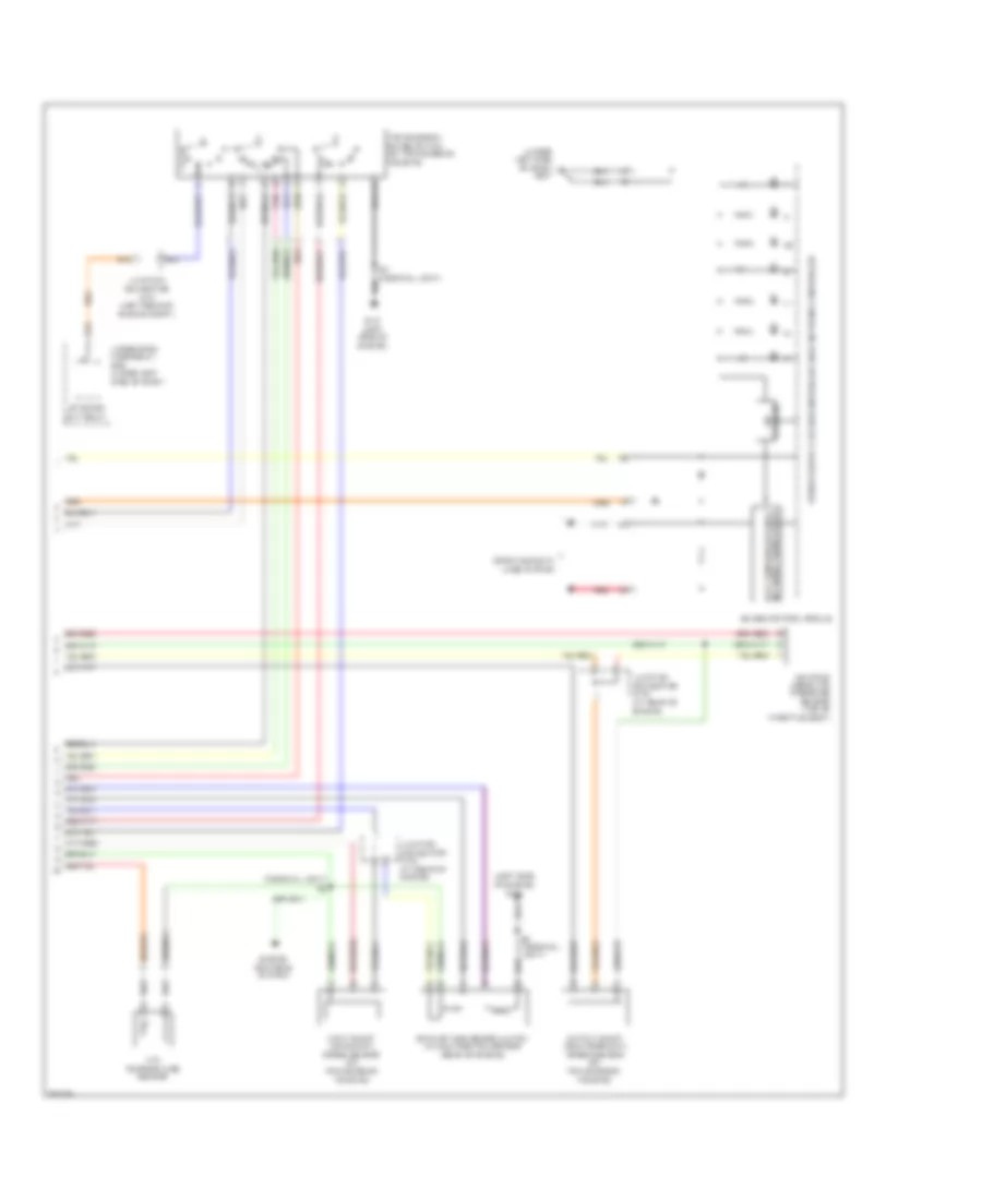 https://portal-diagnostov.com/license.html
Automotive Electricians Portal FZCO
Automotive Electricians Portal FZCO
https://portal-diagnostov.com/license.html
https://portal-diagnostov.com/license.html
Automotive Electricians Portal FZCO
Automotive Electricians Portal FZCOList of elements for Transmission Wiring Diagram (2 of 2) for Honda CR-V EX 2008:
- (left side of engine) g101
- (terminal joint) s4
- (under left side of dash) g501
- A20
- Atf temperature sensor
- B19
- Computer data lines system
- Engine controls system
- Exhaust gas recirculation valve & position sensor (rear of engine)
- F29
- Fast controller area network transceiver
- G101 (left side of engine)
- Gauge control module
- Input shaft (mainshaft) speed sensor (on transmission housing)
- Junction connector c101 (left rear of engine compt)
- Junction connector c103 (at rear of engine)
- Manifold absolute pressure sensor (top of throttle body)
- Output shaft (countershaft) speed sensor (on transmission housing)
- P r
- Pnk
- Red
- S3 (terminal joint)
- Stabilize 10v
- Starter cut relay
- Transmission range switch (on transmission housing)
- Under-dash fuse/relay box (under left side of dash)
TRUNK, TAILGATE, FUEL DOOR
Tailgate Release Wiring Diagram for Honda CR-V EX 2008
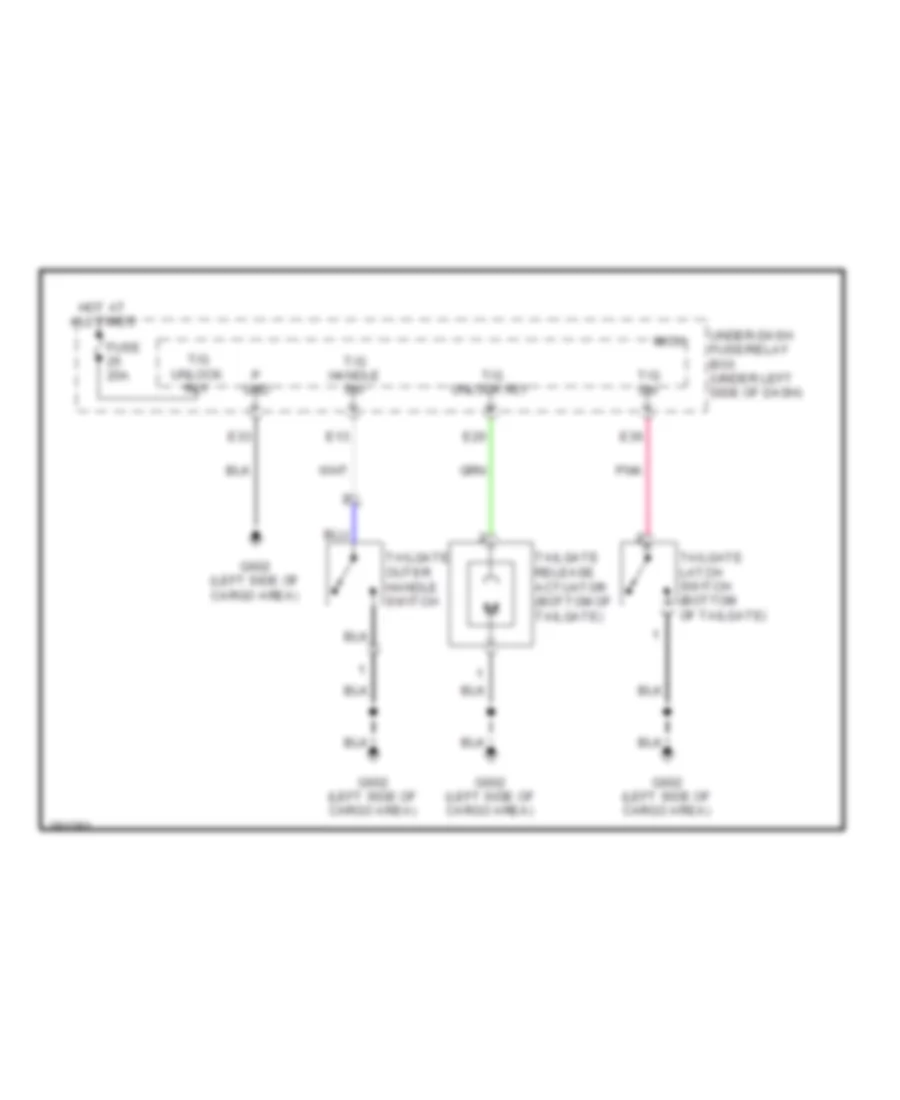 https://portal-diagnostov.com/license.html
Automotive Electricians Portal FZCO
Automotive Electricians Portal FZCO
https://portal-diagnostov.com/license.html
https://portal-diagnostov.com/license.html
Automotive Electricians Portal FZCO
Automotive Electricians Portal FZCOList of elements for Tailgate Release Wiring Diagram for Honda CR-V EX 2008:
- E13
- E20
- E33
- E36
- Fuse 20a
- G602 (left side of cargo area)
- Hot at all times
- Micu
- P gnd
- Pnk
- T/g handle sw
- T/g sw
- T/g unlock rly
- Tailgate latch switch (bottom of tailgate)
- Tailgate outer handle switch
- Tailgate release actuator (bottom of tailgate)
- Under-dash fuse/relay box (under left side of dash)
WARNING SYSTEMS
Chime Wiring Diagram for Honda CR-V EX 2008
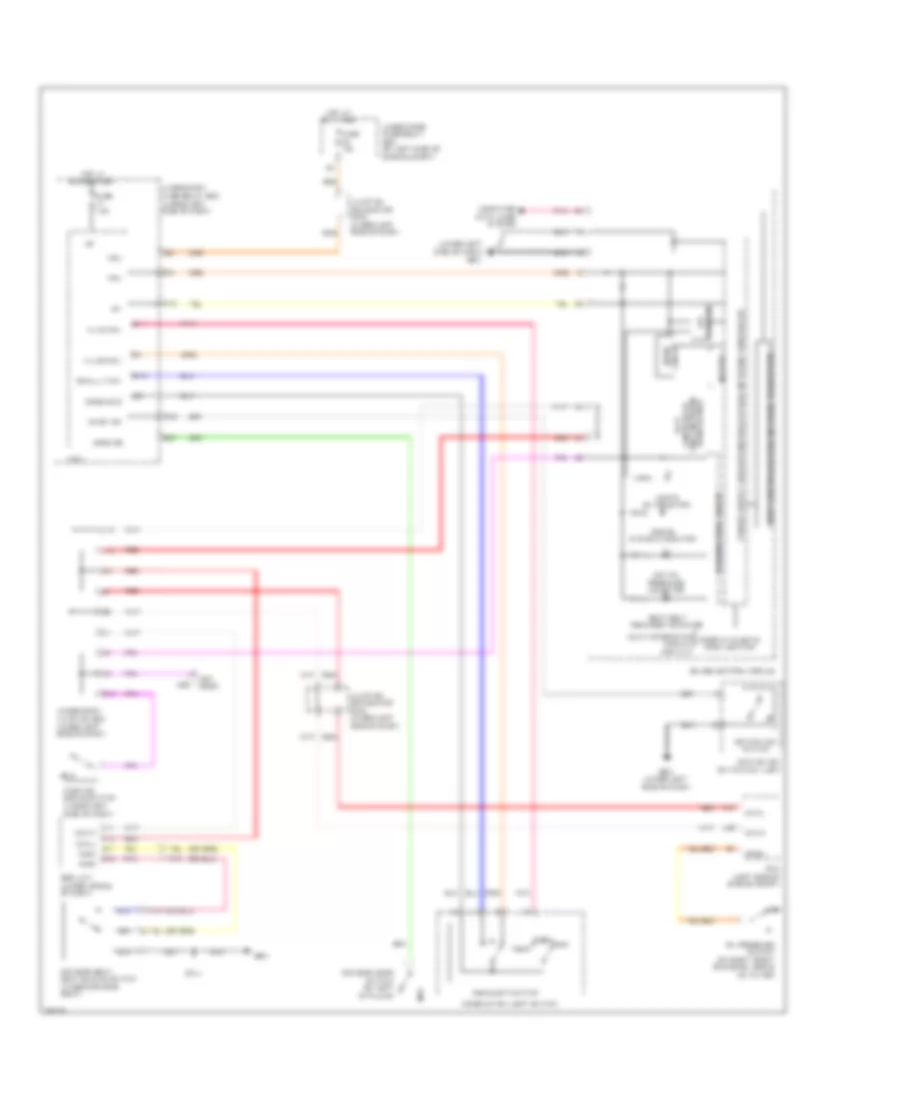 https://portal-diagnostov.com/license.html
Automotive Electricians Portal FZCO
Automotive Electricians Portal FZCO
https://portal-diagnostov.com/license.html
https://portal-diagnostov.com/license.html
Automotive Electricians Portal FZCO
Automotive Electricians Portal FZCOList of elements for Chime Wiring Diagram for Honda CR-V EX 2008:
- (not c507 used)
- (under left side of dash) g501
- 10v stabilize
- A11
- A12
- A36
- A37
- Area network transceiver
- B11
- B12
- Beeper
- Body controller area network transceiver
- Brake system indicator
- Can-h
- Can-l
- Circuit drive
- Combi gnd
- Combination light switch
- Computer data lines system
- Door & tailgate open monitor
- Driver's door switch (on left "b" pillar)
- Driver's seat belt buckle switch (under driver's seat)
- Drswdr
- E37
- Ex-l
- Fast controller
- Flbc
- Flbo
- Fuse 10a
- Fuse 7.5a
- G10
- G501 (under left side of dash)
- G551
- Gauge control module
- H/l off sw
- H/l on sw
- Head
- Headlight switch
- Hot at all times
- Hot in on or start
- Ig key sw
- Ig1
- Ignition key switch
- Ignition key switch/key light
- J12
- J13
- Junction connector c404 (under left side of dash)
- Junction connector c405 (under left side of dash)
- Lights on indicator
- Low oil pressure indicator
- Micu
- Multi-information display (mid) unit
- Off
- Oil pressure switch (on right front of engine, above oil filter)
- Opsw
- P10
- Park
- Parking brake switch (under left side of dash)
- Pcm (left side of engine compt)
- Pnk
- R16
- Red
- S11
- S13
- Seat belt reminder indicator
- Small lt sw
- Srs unit (under middle of dash)
- Under-dash fuse/relay box (under left side of dash)
- Under-dash junction box (under left side of dash)
- Under-hood fuse/relay box (on left side of engine compt)
- Vbu
- Warning drive circuit
Tire Pressure Monitoring Wiring Diagram for Honda CR-V EX 2008
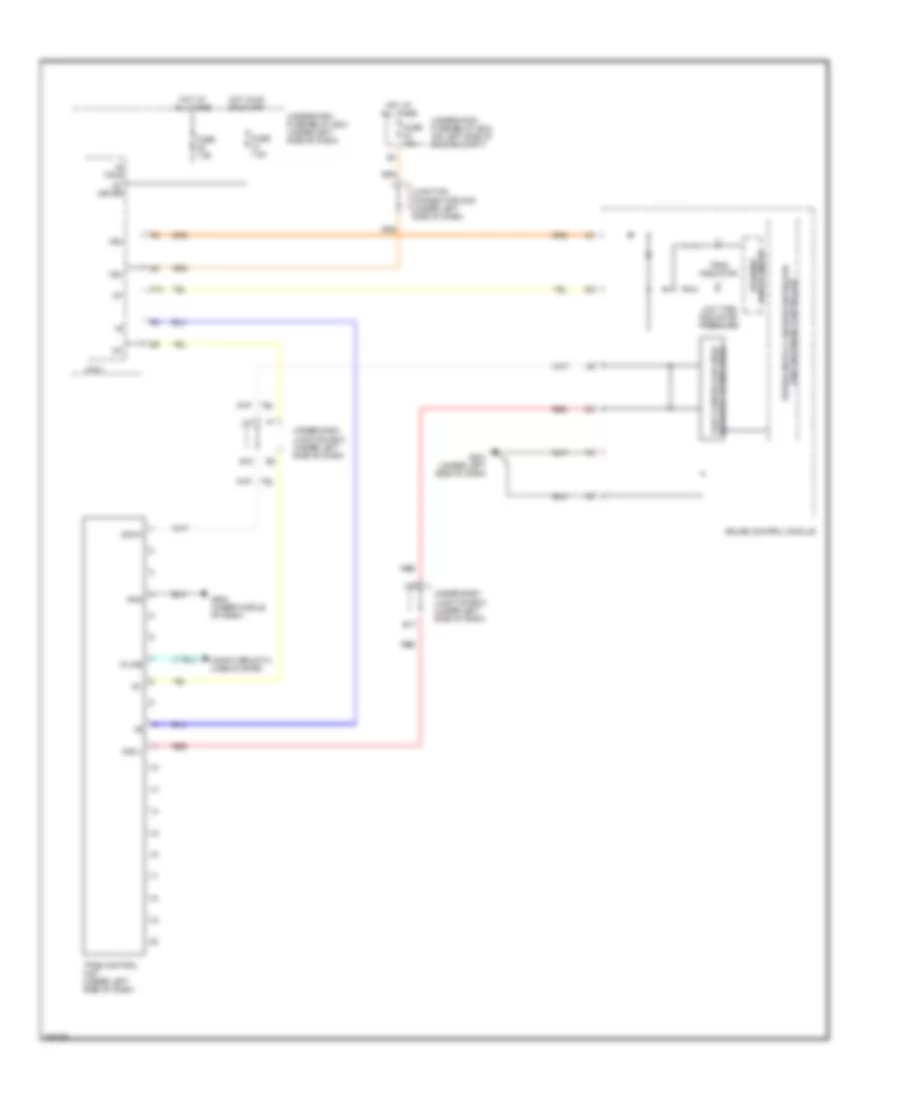 https://portal-diagnostov.com/license.html
Automotive Electricians Portal FZCO
Automotive Electricians Portal FZCO
https://portal-diagnostov.com/license.html
https://portal-diagnostov.com/license.html
Automotive Electricians Portal FZCO
Automotive Electricians Portal FZCOList of elements for Tire Pressure Monitoring Wiring Diagram for Honda CR-V EX 2008:
- +b tpms
- Can-h
- Can-l
- Computer data lines system
- E17
- E18
- Fast controller area network transceiver
- Fuse 10a
- Fuse 7.5a
- G501 (under left side of dash)
- G502 (under middle of dash)
- Gauge control module
- Gnd
- Hot at all times
- Hot in on or start
- Ig1
- Ig1 meter
- J12
- J13
- Junction connector c405 (under left side of dash)
- K-line
- Low tire indicator pressure
- Micu
- P10
- Red
- Tpms control unit (under left side of dash)
- Tpms indicator
- Under-dash fuse/relay box (under left side of dash)
- Under-dash junction box (under left side of dash)
- Under-hood fuse/relay box (on left side of engine compt)
- Vbu
- Warning drive circuit
WIPER/WASHER
Front Wiper/Washer Wiring Diagram for Honda CR-V EX 2008
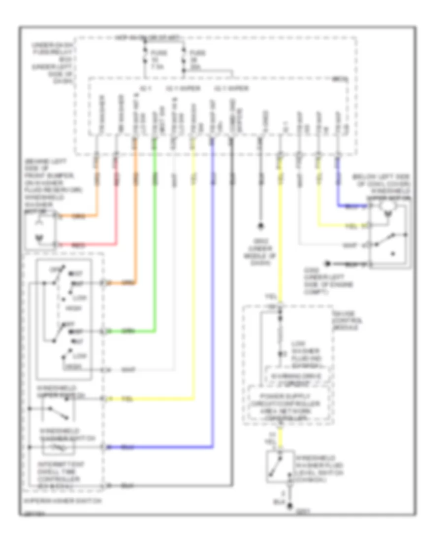 https://portal-diagnostov.com/license.html
Automotive Electricians Portal FZCO
Automotive Electricians Portal FZCO
https://portal-diagnostov.com/license.html
https://portal-diagnostov.com/license.html
Automotive Electricians Portal FZCO
Automotive Electricians Portal FZCOList of elements for Front Wiper/Washer Wiring Diagram for Honda CR-V EX 2008:
- (behind left side of front bumper, on washer fluid reservoir) windshield washer motor
- (below left side of cowl cover) windshield wiper motor
- Combi gnd (wiper)
- F18
- F19
- F32
- F33
- F34
- Fr wash sw
- Fr washer
- Fr wip as
- Fr wip hi
- Fr wip hi & lo sw
- Fr wip int vr+
- Fr wip mist sw
- Fuse 30a
- Fuse 7.5a
- G201
- G302 (under left side of engine compt)
- G502 (under middle of dash)
- Gauge control module
- High
- Hot in on or start
- Ig 1
- Ig 1 wiper
- Int
- Intermittent dwell time controller (ex & ex-l)
- Lo fr wip
- Lo sw fr wip int & s10
- Low
- Low washer fluid ind (canada)
- Micu
- Mist
- Off
- P10
- Red
- Rr washer
- S-gnd2
- S15
- S17
- S20
- T34
- Under-dash fuse/relay box (under left side of dash)
- Warning drive circuit
- Windshield washer fluid level switch (canada)
- Windshield washer switch
- Windshield wiper switch
- Wiper/washer switch
Rear Wiper/Washer Wiring Diagram for Honda CR-V EX 2008
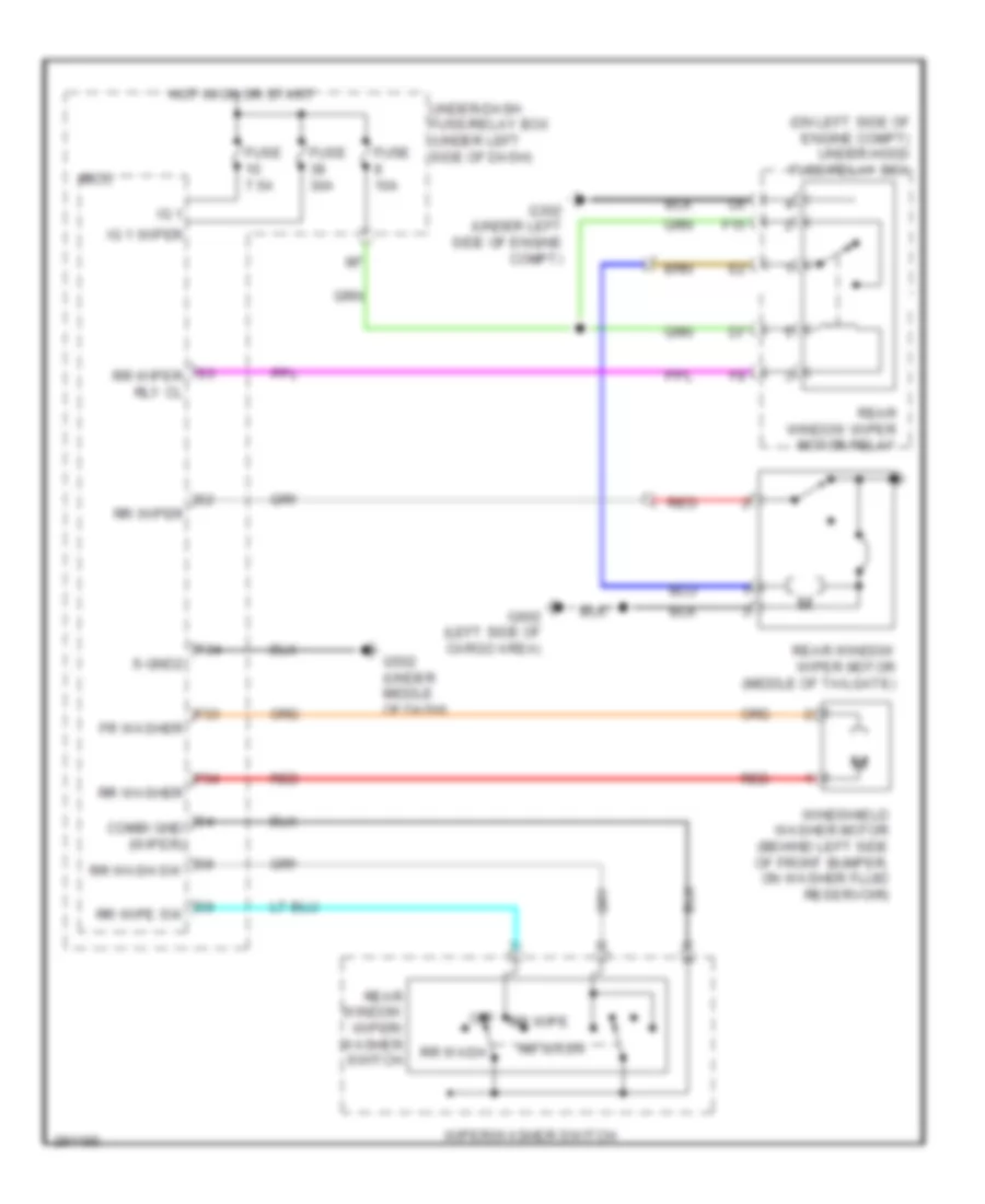 https://portal-diagnostov.com/license.html
Automotive Electricians Portal FZCO
Automotive Electricians Portal FZCO
https://portal-diagnostov.com/license.html
https://portal-diagnostov.com/license.html
Automotive Electricians Portal FZCO
Automotive Electricians Portal FZCOList of elements for Rear Wiper/Washer Wiring Diagram for Honda CR-V EX 2008:
- (on left side of engine compt) under-hood fuse/relay box
- F15
- F33
- F34
- Fr washer
- Fuse 10a
- Fuse 30a
- Fuse 7.5a
- G302 (under left side of engine compt)
- G502 (under middle of dash)
- G602 (left side of cargo area)
- Hot in on or start
- Ig 1
- Ig 1 wiper
- Micu
- Off
- Rear window wiper motor (middle of tailgate)
- Rear window wiper motor relay
- Rear window wiper/ washer switch
- Red
- Rr wash
- Rr washer
- Rr wipe
- Rr wiper
- S-gnd2
- S3 rr wiper rly cl
- S4 combi gnd (wiper)
- S8 rr wash sw
- S9 rr wipe sw
- T34
- Under-dash fuse/relay box (under left side of dash)
- Windshield washer motor (behind left side of front bumper, on washer fluid reservoir)
- Wiper/washer switch

 Čeština
 Dansk
Dansk Deutsch
 Ελληνικά
 English
 English
 Español
 Suomi
Suomi Français
 Français
 עברית
עברית Hrvatski
 Magyar
 Italiano
 한국어
한국어 Nederlands
 Polski
 Português
 Português
 Română
 Русский
 Slovenčina
 Slovenščina
 Svenska
 Türkçe
 中文 (中国)
