AIR CONDITIONING
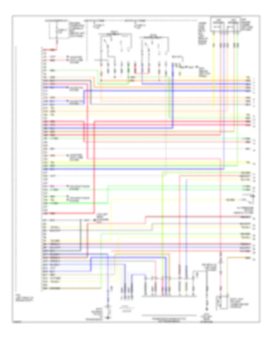
2.4L
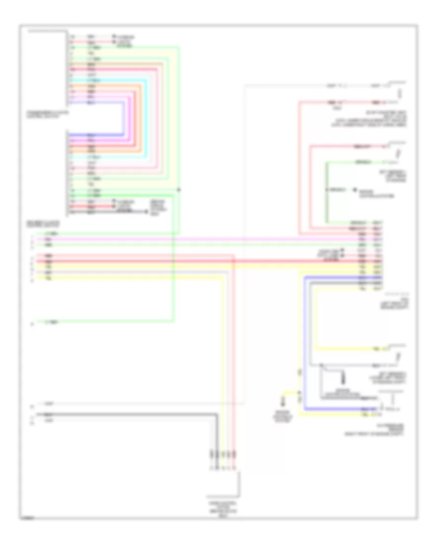
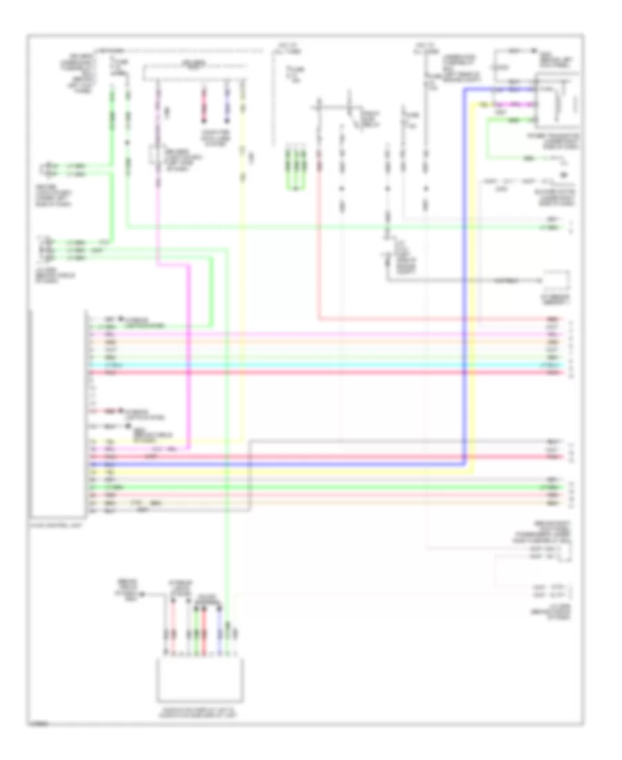
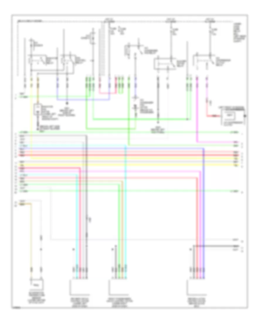
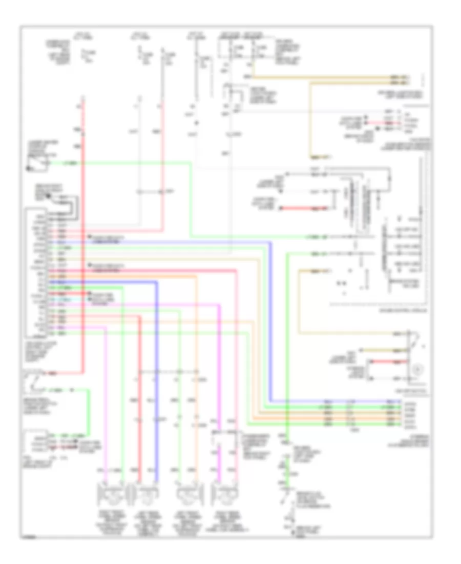
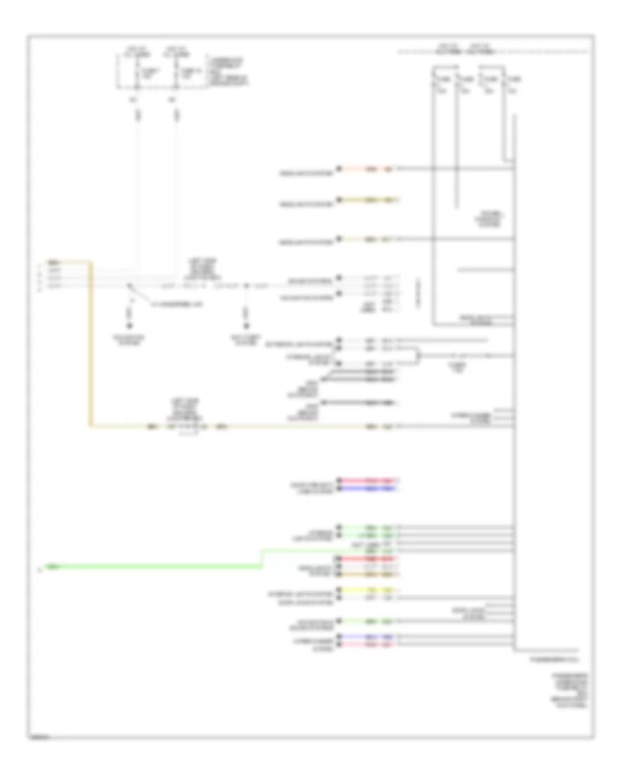
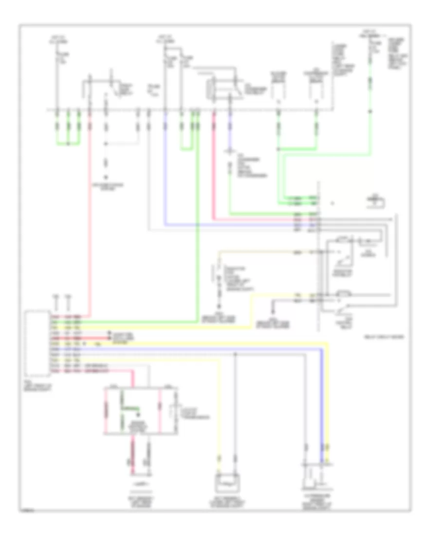
2.4L, Manual A/C Wiring Diagram, with Navigation (1 of 3) for Honda Crosstour EX 2012
 https://portal-diagnostov.com/license.html
Automotive Electricians Portal FZCO
Automotive Electricians Portal FZCO
https://portal-diagnostov.com/license.html
https://portal-diagnostov.com/license.html
Automotive Electricians Portal FZCO
Automotive Electricians Portal FZCO
List of elements for 2.4L, Manual A/C Wiring Diagram, with Navigation (1 of 3) for Honda Crosstour EX 2012:
- (behind middle of dash) g502
- (behind middle of dash) g502 computer data lines system
- (behind right kick panel) passenger's under- dash fuse/relay box
- A10
- A11
- A12
- A13
- A14
- A15
- A16
- A17
- A18
- A19
- A20
- A21
- A22
- A23
- A24
- A25
- A26
- A27
- A28
- Audio-hvac display unit & audio-hvac sub display unit
- Automatic lighting sensor/sunlight sensor (top middle of dash)
- B10
- B11
- B12
- Blower motor (under right side of dash)
- C303
- C306
- C406
- C407
- C507
- Center junction box (under left side of dash)
- Climate control unit
- Computer data lines system
- Driver's junction box (left side of dash)
- Driver's under-dash fuse/relay box (behind left kick panel)
- F22
- F29
- Fuse 10a
- Fuse 15a
- Fuse 7.5a
- G302 (behind left kick panel)
- Hot at all times
- Hot in on
- Humidity sensor
- Humidity/in-car temperature sensor (right of steering column)
- In-car temperature sensor
- Interior lights system
- J/c c503 (behind middle of dash)
- J/c c506 (behind middle of dash)
- Micu
- Navigation unit
- Outside air temperature sensor (behind middle of front bumper)
- P11
- Pgm-fi sub- relay
- Pnk
- Power transistor (under right side of dash)
- Red
- Sound systems
- Under-hood fuse/relay box (left rear of engine compt)
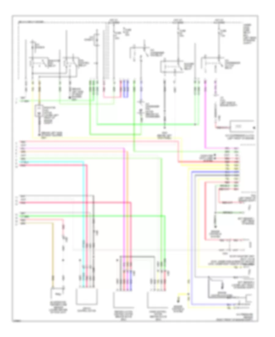
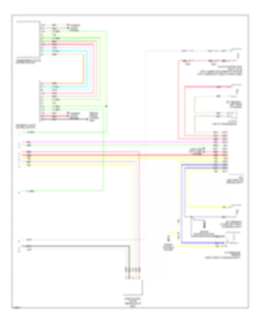
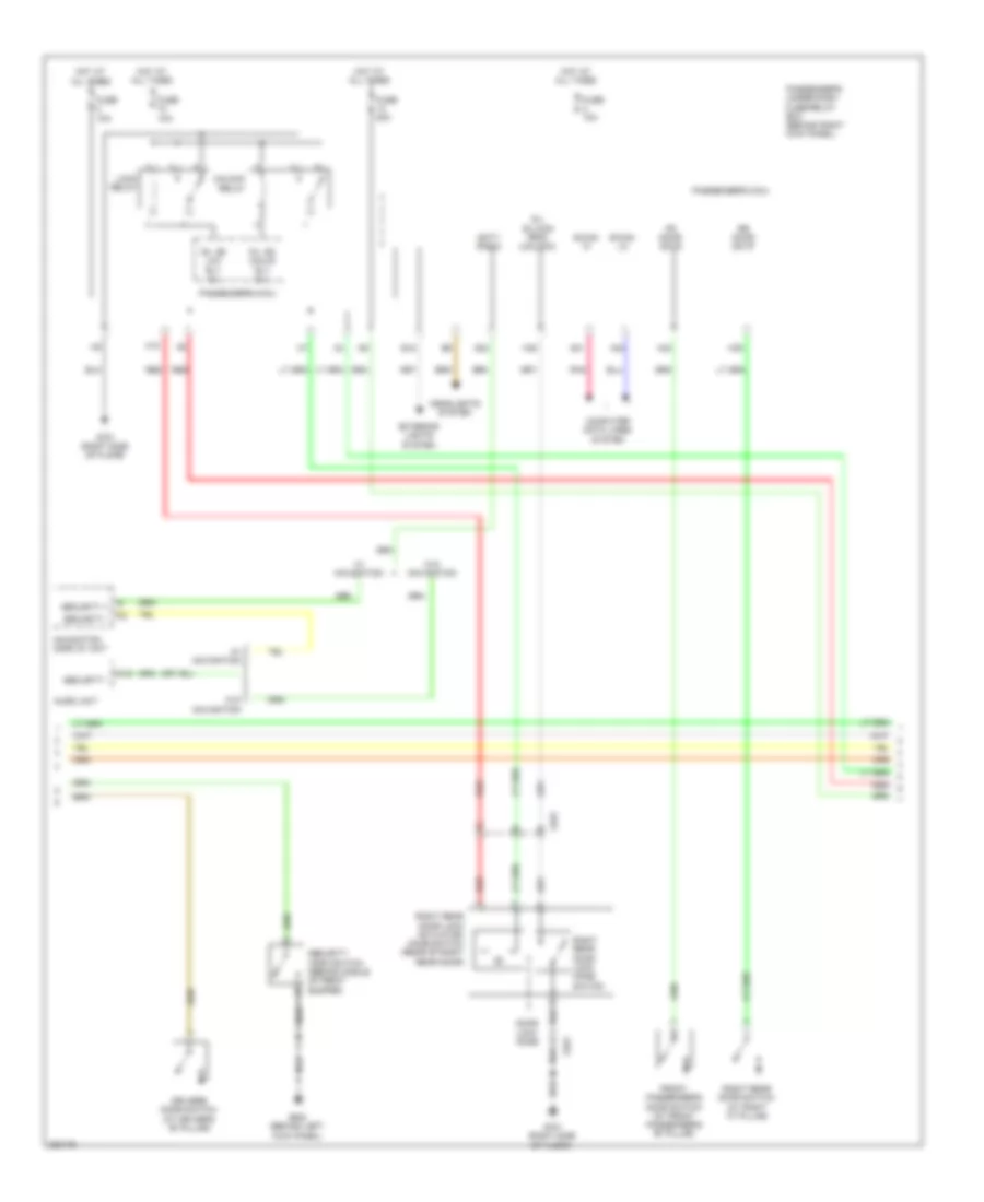
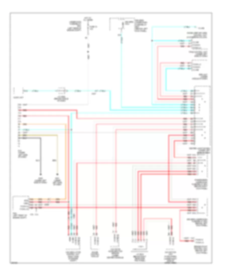
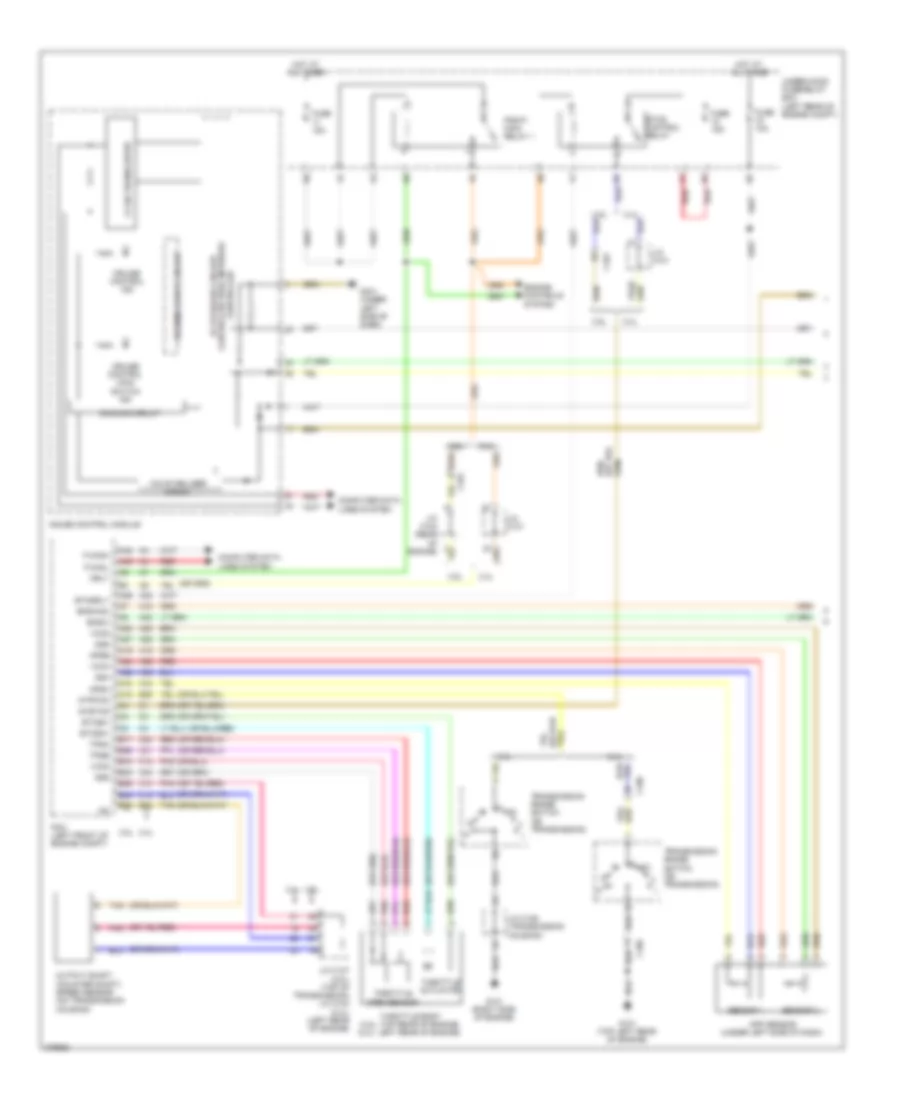
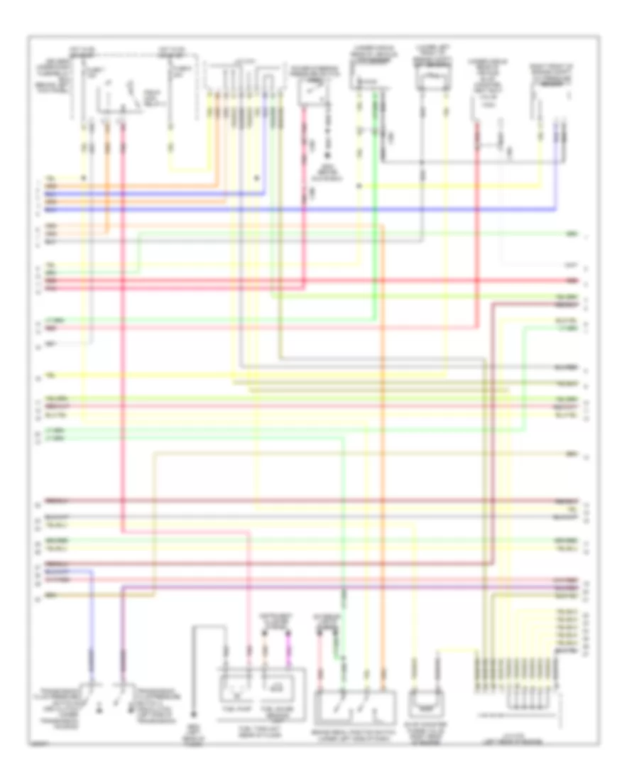
2.4L, Manual A/C Wiring Diagram, with Navigation (2 of 3) for Honda Crosstour EX 2012
 https://portal-diagnostov.com/license.html
Automotive Electricians Portal FZCO
Automotive Electricians Portal FZCO
https://portal-diagnostov.com/license.html
https://portal-diagnostov.com/license.html
Automotive Electricians Portal FZCO
Automotive Electricians Portal FZCOList of elements for 2.4L, Manual A/C Wiring Diagram, with Navigation (2 of 3) for Honda Crosstour EX 2012:
- (behind left side of front bumper) g301
- A/c compressor (left front of engine)
- A/c compressor clutch
- A/c compressor clutch relay
- A/c condenser fan motor (behind a/c condenser)
- A/c condenser fan relay
- A/c diode a
- A/c diode b
- B10
- B11
- B12
- B13
- Blower motor relay
- C101
- C102
- C507
- Driver's air mix control motor (under left side of dash)
- Evaporator temperature sensor (lower center of hvac unit)
- Fan control relay
- Front passenger's air mix control motor (under right side of dash)
- Fuse 3-6 30a
- Fuse 3-8 30a
- Fuse 40a
- Fuse 7.5a
- G301 (behind left side of front bumper)
- G302 (behind left kick panel)
- Hot at all times
- Pnk
- Radiator fan motor (lower left front of engine compt)
- Radiator fan relay
- Recirculation control motor (behind glove box)
- Red
- Relay circuit board
- Under- hood fuse/ relay box (left rear of engine compt)
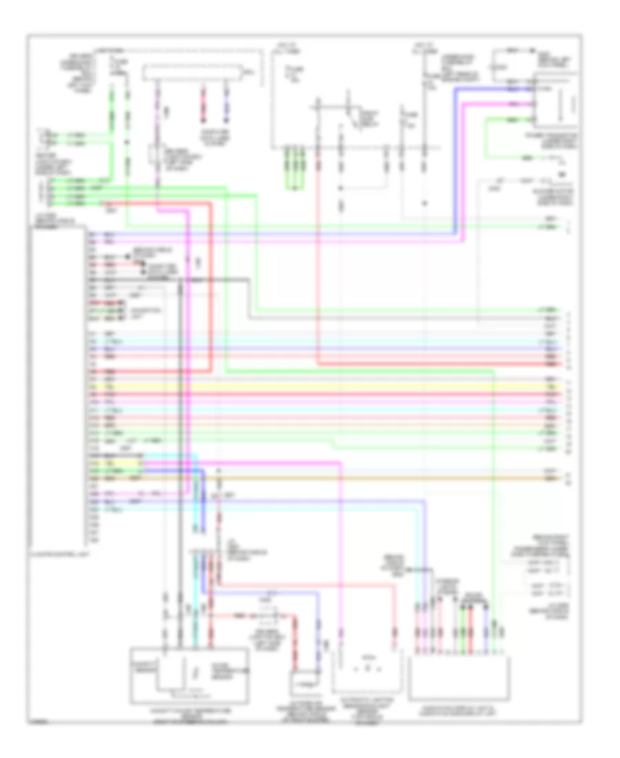
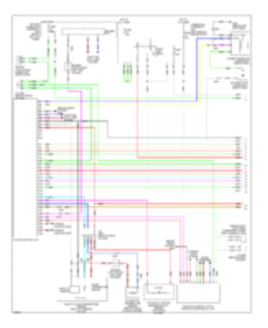
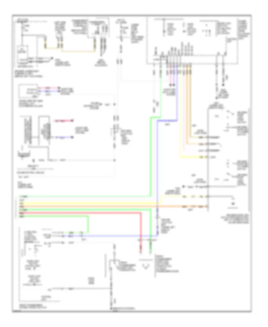
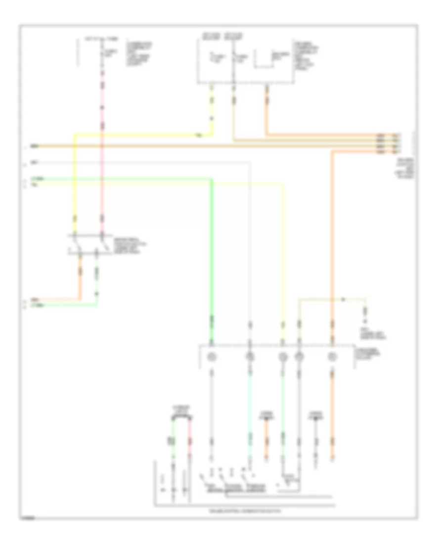
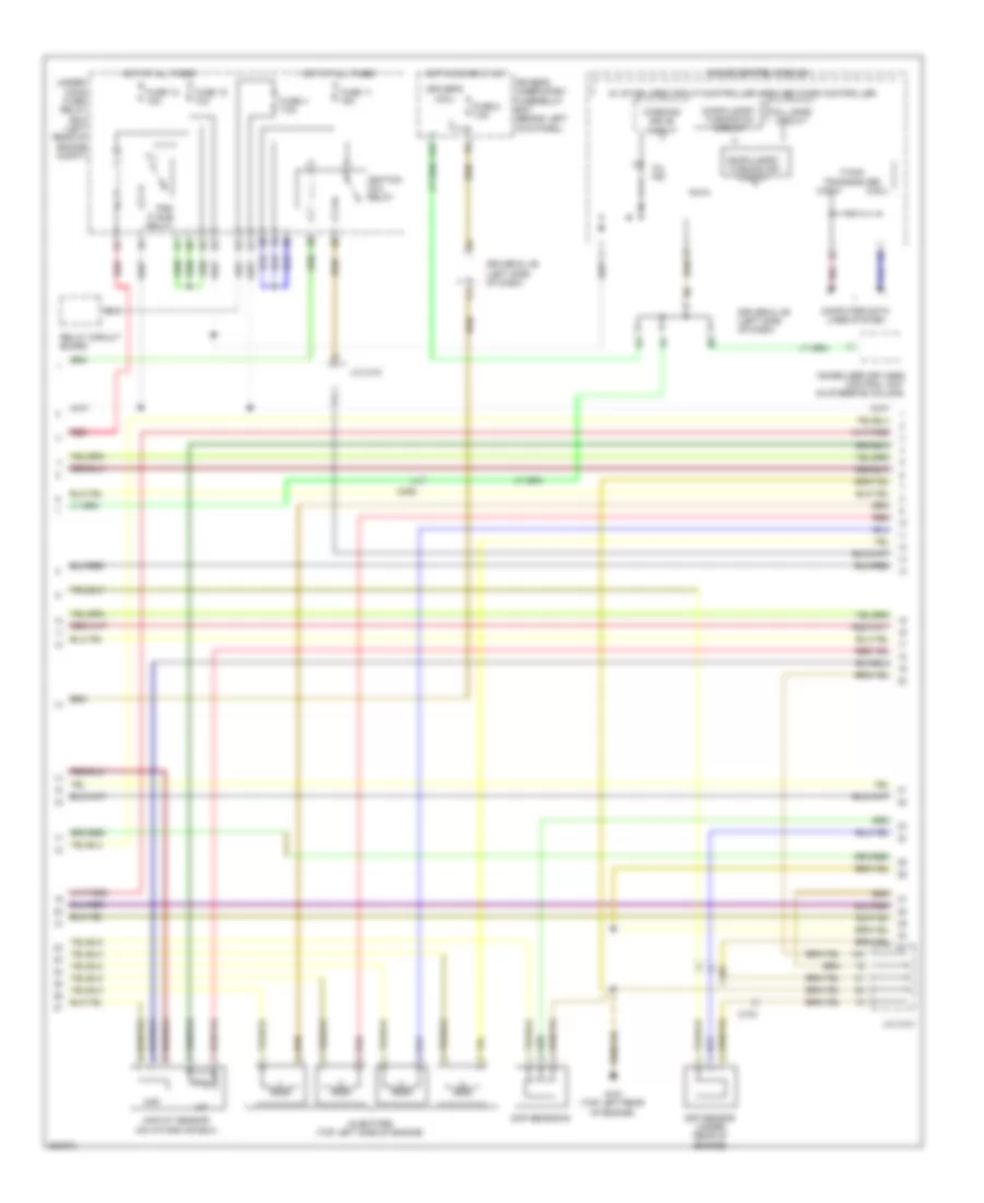
2.4L, Manual A/C Wiring Diagram, with Navigation (3 of 3) for Honda Crosstour EX 2012
 https://portal-diagnostov.com/license.html
Automotive Electricians Portal FZCO
Automotive Electricians Portal FZCO
https://portal-diagnostov.com/license.html
https://portal-diagnostov.com/license.html
Automotive Electricians Portal FZCO
Automotive Electricians Portal FZCOList of elements for 2.4L, Manual A/C Wiring Diagram, with Navigation (3 of 3) for Honda Crosstour EX 2012:
- (behind middle of dash) g502
- A/c pressure sensor (right front of engine compt)
- A10
- A17
- A20
- A22
- A34
- A41
- A44
- A45
- A49
- B24
- B34
- C304
- Computer data lines system
- Driver's climate control switch
- Ect sensor 1 (left rear of engine)
- Ect sensor 2 (lower left front of engine compt)
- Engine controls system
- Evap canister vent shut valve (2wd: under middle rear of vehicle) (4wd: under right side of cargo area)
- Interior lights system
- Mode control motor (behind glove box)
- Passenger's climate control switch
- Pcm (left front of engine compt)
- Pnk
- Red
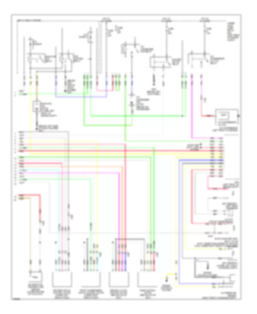
2.4L, Manual A/C Wiring Diagram, without Navigation (1 of 2) for Honda Crosstour EX 2012
 https://portal-diagnostov.com/license.html
Automotive Electricians Portal FZCO
Automotive Electricians Portal FZCO
https://portal-diagnostov.com/license.html
https://portal-diagnostov.com/license.html
Automotive Electricians Portal FZCO
Automotive Electricians Portal FZCOList of elements for 2.4L, Manual A/C Wiring Diagram, without Navigation (1 of 2) for Honda Crosstour EX 2012:
- (behind middle of dash) g502
- (behind right kick panel) passenger's under- dash fuse/relay box
- A/f sensor (sensor 1)
- A16
- Audio-hvac display unit & audio-hvac sub display unit
- Blower motor (under right side of dash)
- C303
- C306
- C407
- C507
- Center junction box (under left side of dash)
- Computer data lines system
- Driver's junction box (left side of dash)
- Driver's micu
- Driver's under-dash fuse/relay box (behind left kick panel)
- F22
- F29
- Fuse 10a
- Fuse 15a
- Fuse 7.5a
- G302 (behind left kick panel)
- G502 (behind middle of dash)
- Hot at all times
- Hot in on
- Hvac control unit
- Interior lights system
- J/c c101 (left side of engine compt)
- J/c c506 (behind middle of dash)
- P11
- Pgm-fi sub- relay
- Pnk
- Power transistor (under right side of dash)
- Q11
- Red
- Sound systems
- Under-hood fuse/relay box (left rear of engine compt)
2.4L, Manual A/C Wiring Diagram, without Navigation (2 of 2) for Honda Crosstour EX 2012
 https://portal-diagnostov.com/license.html
Automotive Electricians Portal FZCO
Automotive Electricians Portal FZCO
https://portal-diagnostov.com/license.html
https://portal-diagnostov.com/license.html
Automotive Electricians Portal FZCO
Automotive Electricians Portal FZCOList of elements for 2.4L, Manual A/C Wiring Diagram, without Navigation (2 of 2) for Honda Crosstour EX 2012:
- (behind left side of front bumper) g301
- A/c compressor clutch (left front of engine)
- A/c compressor clutch relay
- A/c condenser fan motor (behind a/c condenser)
- A/c condenser fan relay
- A/c diode a
- A/c diode b
- A/c pressure sensor (right front of engine compt)
- A10
- A17
- A20
- A22
- A34
- A41
- A44
- A45
- A49
- Air mix control motor
- B10
- B11
- B12
- B13
- B24
- B34
- Blower motor relay
- C102
- C304
- C507
- Computer data lines system
- Ect sensor 1 (left rear of engine)
- Ect sensor 2 (lower left front of engine compt)
- Engine controls system
- Evap canister vent shut valve (2wd: under middle rear of vehicle) (4wd: under right side of cargo area)
- Evaporator temperature sensor (lower center of hvac unit)
- Fan control relay
- Fuse 20a
- Fuse 3-6 30a
- Fuse 40a
- Fuse 7.5a
- G302 (behind left kick panel)
- Hot at all times
- J/c c101 (left side of engine compt)
- Mode control motor (behind glove box)
- Pcm (left front of engine compt)
- Pnk
- Radiator fan motor (lower left front of engine compt)
- Radiator fan relay
- Recirculation control motor (behind glove box)
- Red
- Relay circuit board
- Under- hood fuse/ relay box (left rear of engine compt)
3.5L
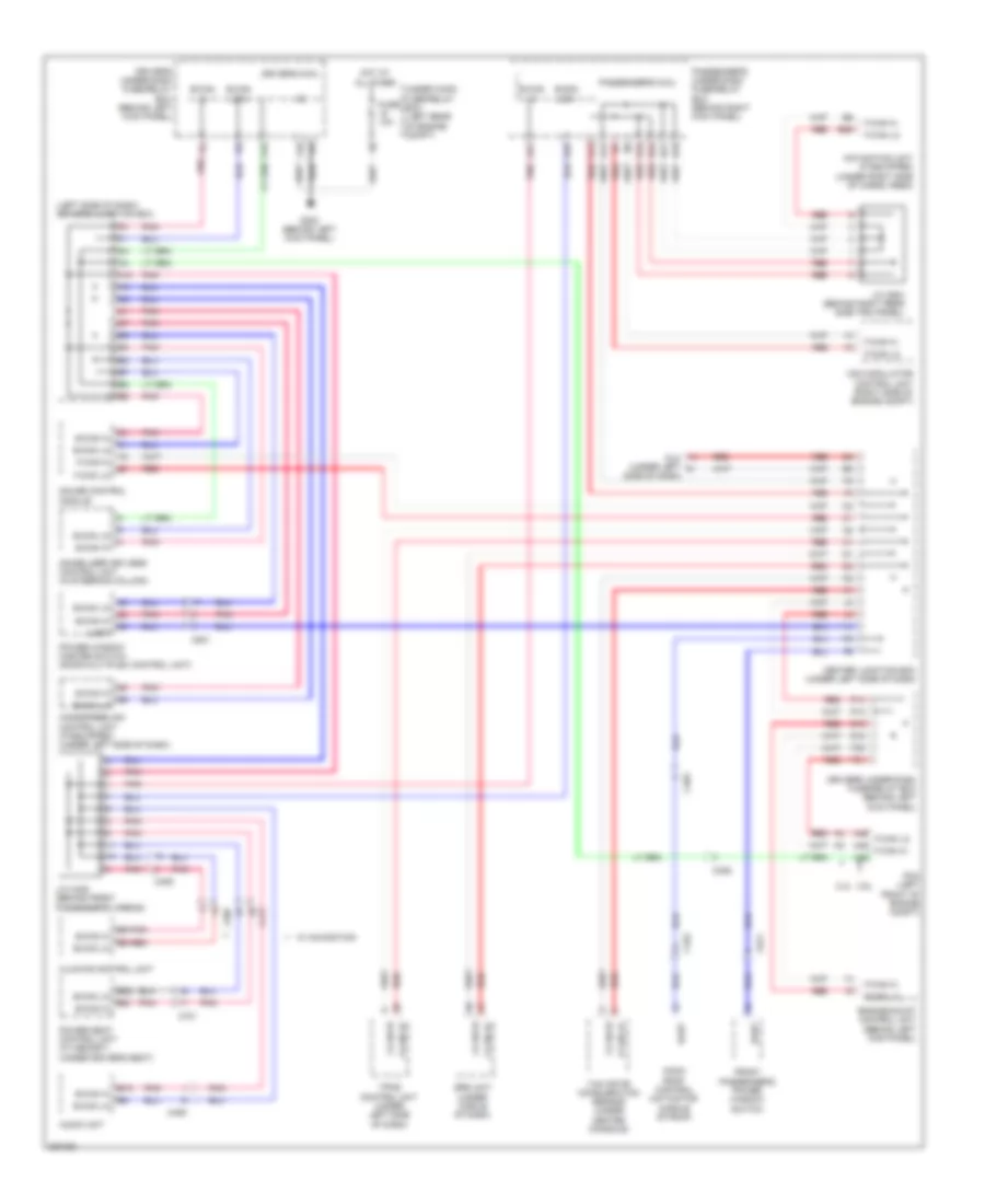
3.5L, Automatic A/C Wiring Diagram, with Navigation (1 of 3) for Honda Crosstour EX 2012
 https://portal-diagnostov.com/license.html
Automotive Electricians Portal FZCO
Automotive Electricians Portal FZCO
https://portal-diagnostov.com/license.html
https://portal-diagnostov.com/license.html
Automotive Electricians Portal FZCO
Automotive Electricians Portal FZCOList of elements for 3.5L, Automatic A/C Wiring Diagram, with Navigation (1 of 3) for Honda Crosstour EX 2012:
- (behind middle of dash) g502
- (behind right kick panel) passenger's under- dash fuse/relay box
- A10
- A11
- A12
- A13
- A14
- A15
- A16
- A17
- A18
- A19
- A20
- A21
- A22
- A23
- A24
- A25
- A26
- A27
- A28
- Audio-hvac display unit & audio-hvac sub display unit
- Automatic lighting sensor/sunlight sensor (top middle of dash)
- B10
- B11
- B12
- Blower motor (under right side of dash)
- C303
- C306
- C406
- C407
- C507
- Center junction box (under left side of dash)
- Climate control unit
- Computer data lines system
- Driver's junction box (left side of dash)
- Driver's under-dash fuse/relay box (behind left kick panel)
- F22
- F29
- Fuse 10a
- Fuse 15a
- Fuse 7.5a
- G302 (behind left kick panel)
- Hot at all times
- Hot in on
- Humidity sensor
- Humidity/in-car temperature sensor (right of steering column)
- In-car temperature sensor
- Interior lights system
- J/c c503 (behind middle of dash)
- J/c c506 (behind middle of dash)
- Micu
- Navigation unit
- Outside air temperature sensor (behind middle of front bumper)
- P11
- Pgm-fi sub- relay
- Pnk
- Power transistor (under right side of dash)
- Red
- Sound systems
- Under-hood fuse/relay box (left rear of engine compt)
3.5L, Automatic A/C Wiring Diagram, with Navigation (2 of 3) for Honda Crosstour EX 2012
 https://portal-diagnostov.com/license.html
Automotive Electricians Portal FZCO
Automotive Electricians Portal FZCO
https://portal-diagnostov.com/license.html
https://portal-diagnostov.com/license.html
Automotive Electricians Portal FZCO
Automotive Electricians Portal FZCOList of elements for 3.5L, Automatic A/C Wiring Diagram, with Navigation (2 of 3) for Honda Crosstour EX 2012:
- (behind left side of front bumper) g301
- (left front of engine) a/c compressor
- A/c compressor clutch
- A/c compressor clutch relay
- A/c condenser fan motor (behind a/c condenser)
- A/c condenser fan relay
- A/c diode a
- A/c diode b
- B10
- B11
- B12
- B13
- Blower motor relay
- C101
- C507
- Driver's air mix control motor (under left side of dash)
- Evaporator temperature sensor (lower center of hvac unit)
- Fan control relay
- Front passenger's air mix control motor (under right side of dash)
- Fuse 3-6 30a
- Fuse 3-8 30a
- Fuse 40a
- Fuse 7.5a
- G301 (behind left side of front bumper)
- G302 (behind left kick panel)
- Hot at all times
- Pnk
- Radiator fan motor (lower left front of engine compt)
- Radiator fan relay
- Recirculation control motor (behind glove box)
- Red
- Relay circuit board
- Under- hood fuse/ relay box (left rear of engine compt)
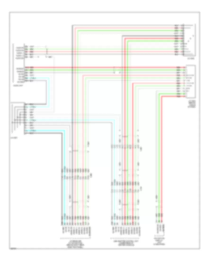
3.5L, Automatic A/C Wiring Diagram, with Navigation (3 of 3) for Honda Crosstour EX 2012
 https://portal-diagnostov.com/license.html
Automotive Electricians Portal FZCO
Automotive Electricians Portal FZCO
https://portal-diagnostov.com/license.html
https://portal-diagnostov.com/license.html
Automotive Electricians Portal FZCO
Automotive Electricians Portal FZCOList of elements for 3.5L, Automatic A/C Wiring Diagram, with Navigation (3 of 3) for Honda Crosstour EX 2012:
- (behind middle of dash) g502
- A/c pressure sensor (right front of engine compt)
- A13
- A21
- A22
- A36
- A37
- A40
- A45
- A48
- A49
- C16
- C304
- C32
- C603
- Computer data lines system
- Driver's climate control switch
- Ect sensor 1 (left rear of engine)
- Ect sensor 2 (lower left front of engine compt)
- Engine controls system
- Evap canister vent shut valve (2wd: under middle rear of vehicle) (4wd: under right side of cargo area)
- Interior lights system
- J/c c107 (top of transmission)
- Mode control motor (behind glove box)
- Passenger's climate control switch
- Pcm (left front of engine compt)
- Pnk
- Red
3.5L, Automatic A/C Wiring Diagram, without Navigation (1 of 2) for Honda Crosstour EX 2012
 https://portal-diagnostov.com/license.html
Automotive Electricians Portal FZCO
Automotive Electricians Portal FZCO
https://portal-diagnostov.com/license.html
https://portal-diagnostov.com/license.html
Automotive Electricians Portal FZCO
Automotive Electricians Portal FZCOList of elements for 3.5L, Automatic A/C Wiring Diagram, without Navigation (1 of 2) for Honda Crosstour EX 2012:
- (behind middle of dash) g502
- (behind right kick panel) passenger's under- dash fuse/relay box
- A10
- A11
- A12
- A13
- A14
- A15
- A16
- A17
- A18
- A19
- A20
- A21
- A22
- A23
- A24
- A25
- A26
- A27
- A28
- Audio-hvac display unit & audio-hvac sub display unit
- Automatic lighting sensor/sunlight sensor (top middle of dash)
- B10
- B11
- B12
- Blower motor (under right side of dash)
- C303
- C306
- C406
- C407
- C507
- Center junction box (under left side of dash)
- Climate control unit
- Computer data lines system
- Driver's junction box (left side of dash)
- Driver's micu
- Driver's under-dash fuse/relay box (behind left kick panel)
- F22
- F29
- Fuse 10a
- Fuse 15a
- Fuse 7.5a
- G302 (behind left kick panel)
- Hot at all times
- Hot in on
- Humidity sensor
- Humidity/in-car temperature sensor (right of steering column)
- In-car temperature sensor
- Interior lights system
- J/c c503 (behind middle of dash)
- J/c c506 (behind middle of dash)
- Outside air temperature sensor (behind middle of front bumper)
- P11
- Pgm-fi sub- relay
- Pnk
- Power transistor (under right side of dash)
- Red
- Sound systems
- Under-hood fuse/relay box (left rear of engine compt)
3.5L, Automatic A/C Wiring Diagram, without Navigation (2 of 2) for Honda Crosstour EX 2012
 https://portal-diagnostov.com/license.html
Automotive Electricians Portal FZCO
Automotive Electricians Portal FZCO
https://portal-diagnostov.com/license.html
https://portal-diagnostov.com/license.html
Automotive Electricians Portal FZCO
Automotive Electricians Portal FZCOList of elements for 3.5L, Automatic A/C Wiring Diagram, without Navigation (2 of 2) for Honda Crosstour EX 2012:
- (behind left side of front bumper) g301
- A/c compressor (left front of engine)
- A/c compressor clutch
- A/c compressor clutch relay
- A/c condenser fan motor (behind a/c condenser)
- A/c condenser fan relay
- A/c diode a
- A/c diode b
- A/c pressure sensor (right front of engine compt)
- A13
- A21
- A22
- A36
- A37
- A40
- A45
- A48
- A49
- B10
- B11
- B12
- B13
- Blower motor relay
- C101
- C16
- C304
- C32
- C507
- Computer data lines system
- Driver's air mix control motor (under left side of dash)
- Ect sensor 1 (left rear of engine)
- Ect sensor 2 (lower left front of engine compt)
- Engine controls system
- Evap canister vent shut valve (2wd: under middle rear of vehicle) (4wd: under right side of cargo area)
- Evaporator temperature sensor (lower center of hvac unit)
- Fan control relay
- Front passenger's air mix control motor (under right side of dash)
- Fuse 3-6 30a
- Fuse 3-8 30a
- Fuse 40a
- Fuse 7.5a
- G302 (behind left kick panel)
- Hot at all times
- J/c c107 (top of transmission)
- Mode control motor (behind glove box)
- Pcm (left front of engine compt)
- Pnk
- Radiator fan motor (lower left front of engine compt)
- Radiator fan relay
- Recirculation control motor (behind glove box)
- Red
- Relay circuit board
- Under- hood fuse/ relay box (left rear of engine compt)
ANTI-LOCK BRAKES
Anti-lock Brakes Wiring Diagram for Honda Crosstour EX 2012
 https://portal-diagnostov.com/license.html
Automotive Electricians Portal FZCO
Automotive Electricians Portal FZCO
https://portal-diagnostov.com/license.html
https://portal-diagnostov.com/license.html
Automotive Electricians Portal FZCO
Automotive Electricians Portal FZCOList of elements for Anti-lock Brakes Wiring Diagram for Honda Crosstour EX 2012:
- (behind right side of front bumper) g202
- (under center console) parking brake switch
- 2.4l
- 3.5l
- 5v stabilizer circuit/ can controller
- A42
- A48 f-can h
- A49 f-can l
- Abs ind (led)
- Bksw
- Brake fluid level switch (on brake fluid reservoir)
- Brake pedal position switch (under left side of dash)
- Brake system ind (led)
- C201
- C202
- C306
- C401
- Can h
- Can l
- Center junction box (under left side of dash)
- Computer data lines system
- Driver's junction box (left side of dash)
- Driver's under-dash fuse/relay box (behind left kick panel)
- E10
- F can transceiver
- F-can h
- F-can l
- F-canh
- F-canl
- Fl+
- Fl-
- Fr+
- Fr-
- Fsr +b
- Fuse 10a
- Fuse 2-2 40a
- Fuse 2-3 30a
- Fuse 20a
- Fuse 7.5a
- G401 (under left side of dash)
- G402 (under left side of dash)
- G403 (behind middle of dash)
- Gauge control module
- Gnd
- H22
- H23
- Hot at all times
- Hot in on or start
- Ig1
- Interior lights system
- K-line
- Left front wheel speed sensor (on left front suspension knuckle)
- Left rear wheel speed sensor (on left rear wheel hub assembly)
- M-gnd
- Mr +b
- Passenger's under-dash fuse/relay box (behind right kick panel)
- Pcm (left front of engine compt)
- Pnk
- Red
- Right front wheel speed sensor (on right front suspension knuckle)
- Right rear wheel speed sensor (on right rear wheel hub assembly)
- Rl+
- Rl-
- Rr+
- Rr-
- Sgnd
- Steering angle sensor (in steering column)
- Str-a
- Str-b
- Str-d
- Str-z
- Strb
- Svcc
- Under-hood fuse/relay box (left rear of engine compt)
- Vsa ind (led)
- Vsa modulator control unit (right side of engine compt)
- Vsa off ind
- Vsa off switch
- Warning drive circuit
- Wen
- Yaw rate- acceleration sensor (under center console)
ANTI-THEFT
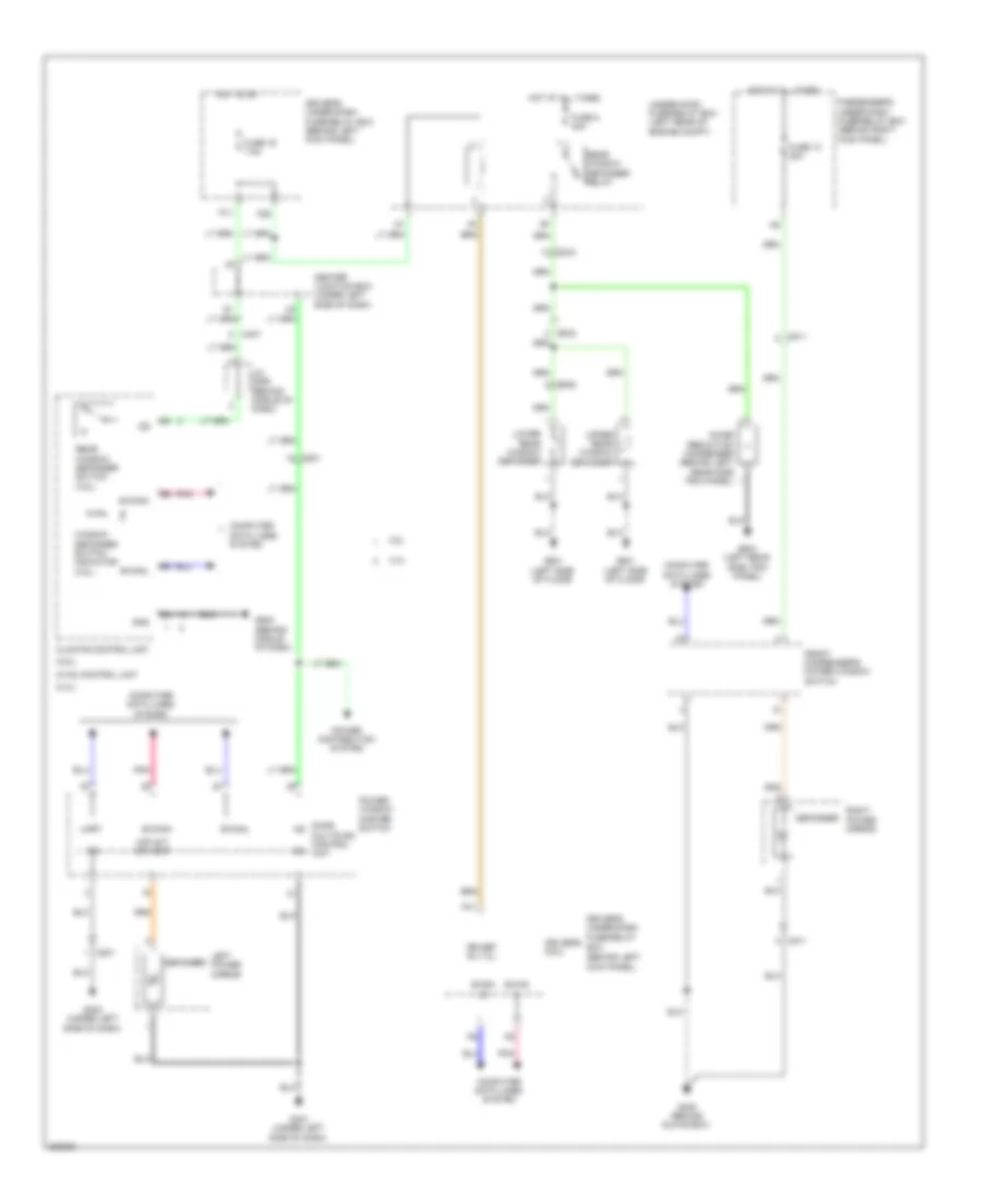
Forced Entry Wiring Diagram (1 of 3) for Honda Crosstour EX 2012
 https://portal-diagnostov.com/license.html
Automotive Electricians Portal FZCO
Automotive Electricians Portal FZCO
https://portal-diagnostov.com/license.html
https://portal-diagnostov.com/license.html
Automotive Electricians Portal FZCO
Automotive Electricians Portal FZCOList of elements for Forced Entry Wiring Diagram (1 of 3) for Honda Crosstour EX 2012:
- (right side of engine) g101
- (top left rear of engine) g101
- 2.4l
- 3.5l
- Atp-p
- B-can hi
- B-can low
- C101
- C106
- C401
- C601
- C651
- C821
- Computer data lines system
- D/l dr fr unlck rly cl-
- D/l dr lck rly cl-
- D/l dr unlock rly cl-
- D/l sil-con sw rr-l (unlock)
- D10
- D12
- D15
- D16
- Door lock knob
- Driver's micu
- Driver's under-dash fuse/relay box (behind left kick panel)
- Driver's unlock relay
- Eng hood sw
- Exterior lights system
- F13
- F17
- F23
- F32
- Fr door sw l
- Fuel fill door lock actuator (behind left rear side trim panel)
- Fuse 10a
- Fuse 15a
- Fuse 20a
- Fuse 7.5a
- G302 (behind left kick panel)
- G403 (behind middle of dash)
- G601 (left side of floor)
- Headlights system
- Horn relay
- Horns system
- Hot at all times
- Hot in on
- J/c c101
- J/c c106 (transmission housing)
- J/c c671 (right side of tailgate)
- Key interlock solenoid/ ignition key switch/ ignition key light
- Key sw
- Left rear door lock actuator/ knob switch (rear of left rear door)
- Left rear door lock knob switch
- Left rear door switch (at left "c" pillar)
- Lock relay
- Lr door sw l
- P11
- Pnk
- Q13
- Red
- Shift interlock system
- T/g act rly cl-
- T/g handle sw
- T/g sw
- Tailgate actuator relay
- Tailgate latch switch
- Tailgate outer handle switch (middle of tailgate)
- Tailgate release actuator
- Tailgate release actuator/latch switch (middle of tailgate)
- Transmission range switch (on transmission)
- Under-hood fuse/relay box (left rear of engine compt)
- Unlock relay
Forced Entry Wiring Diagram (2 of 3) for Honda Crosstour EX 2012
 https://portal-diagnostov.com/license.html
Automotive Electricians Portal FZCO
Automotive Electricians Portal FZCO
https://portal-diagnostov.com/license.html
https://portal-diagnostov.com/license.html
Automotive Electricians Portal FZCO
Automotive Electricians Portal FZCOList of elements for Forced Entry Wiring Diagram (2 of 3) for Honda Crosstour EX 2012:
- A12
- A21
- A34
- Audio unit
- B-can hi
- B-can lo
- C831
- Computer data lines system
- D/l as lck rly cl-
- D/l as unlck rly cl-
- D/l sil-con rr-r (unlock)
- D23
- Door lock knob
- Driver's door switch (at driver's "b" pillar)
- E18
- Exterior lights system
- Fr door sw r
- Front passenger's door switch (at front passenger's "b" pillar)
- Fuse 10a
- Fuse 20a
- G302 (behind left kick panel)
- G701 (right side of floor)
- H10
- H24
- H35
- H38
- Headlights system
- Hot at all times
- Lock relay
- Navigation display unit
- Passenger's micu
- Passenger's under-dash fuse/relay box (behind right kick panel)
- Pnk
- Red
- Right rear door lock actuator/ knob switch (rear of right rear door)
- Right rear door lock knob switch
- Right rear door switch (at right "c" pillar)
- Rr door sw r
- Scty radio
- Security +
- Security -
- Security hood switch (behind middle of front bumper)
- Unlock relay
- W/ navigation
- W/o navigation
Forced Entry Wiring Diagram (3 of 3) for Honda Crosstour EX 2012
 https://portal-diagnostov.com/license.html
Automotive Electricians Portal FZCO
Automotive Electricians Portal FZCO
https://portal-diagnostov.com/license.html
https://portal-diagnostov.com/license.html
Automotive Electricians Portal FZCO
Automotive Electricians Portal FZCOList of elements for Forced Entry Wiring Diagram (3 of 3) for Honda Crosstour EX 2012:
- (behind glove box) g405
- (left side of dash) driver's junction box
- 0) neutral 1) lock 2) unlock door lock switch
- 2.4l
- 3.5l
- 5v stabilizer circuit/ controller area network controller
- A28
- B can hi
- B can lo
- B-canh
- B-canl
- Blinking circuit
- Body controller area network
- C801
- C811
- Center junction box (under left side of dash)
- Computer data lines system
- Control unit
- Dlc (under left side of dash)
- Door lock knob
- Door lock switch 0) neutral 1) lock 2) unlock
- Door lock switch lock light
- Door lock switch unlock light
- Driver's door key cylinder switch
- Driver's door lock actuator/knob switch/ key cylinder switch (on driver's door)
- Driver's door lock knob switch
- Driver's junction box (left side of dash)
- Driver's micu
- Driver's under-dash fuse/relay box (behind left kick panel)
- E14
- E15
- Front passenger's door lock actuator/ knob switch (in front passenger's door)
- Front passenger's door lock knob switch
- Front passenger's power window switch
- Fuse 10a
- Fuse 7.5a
- G203 (behind glove box)
- G401 (under left side of dash)
- G402 (under left side of dash)
- Gauge control module
- Hot at all times
- Hot in on or start
- Ig1
- Ig1 meter
- Ig2
- Immobilizer keyless control unit (in steering column)
- Kc dr lock
- Kc dr ul
- Key
- Lock
- Meter
- P-gnd
- Passenger's micu
- Passenger's under-dash fuse/relay box (behind right kick panel)
- Pnk
- Power distribution system
- Power window master switch (door multiplex control unit)
- Q10 micu-p
- R8 micu-p
- Red
- S-gnd
- Security ind
- Sil as ul
- Sil dr lock
- Sil dr ul
- Transceiver
- Uart
- Under- hood fuse/ relay box (left rear of engine compt)
- Unlock
- Vbu
- Vmp as uart
- Vmp dr
Immobilizer Wiring Diagram for Honda Crosstour EX 2012
 https://portal-diagnostov.com/license.html
Automotive Electricians Portal FZCO
Automotive Electricians Portal FZCO
https://portal-diagnostov.com/license.html
https://portal-diagnostov.com/license.html
Automotive Electricians Portal FZCO
Automotive Electricians Portal FZCOList of elements for Immobilizer Wiring Diagram for Honda Crosstour EX 2012:
- (top left rear of engine) g101
- (under left side of dash) g401
- (under left side of dash) g402
- +b back-
- 2.4l
- 3.5l
- 4wd
- 5v stabilize circuit/controller area network controller
- A11
- A30
- A41
- A46
- A48
- A49
- B-can
- B-can hi
- B-can lo
- B41
- B42
- C10
- C101
- C306
- C35
- C402
- C41
- C411
- C49
- Circuit drive warning
- Computer data lines system
- Dlc (under left side of dash)
- Driver's
- Driver's junction box (left side of dash)
- Driver's micu
- Driver's under-dash fuse/relay box (behind left kick panel)
- F-canh
- F-canl
- F12
- F16
- F33
- Fuel tank unit (4wd: top of fuel tank) (2wd: rear of floor)
- Fuse 10a
- Fuse 15a
- Fuse 20a
- Fuse 7.5a
- G101 (right side of engine)
- G101 (top left rear of engine)
- G403 (behind middle of dash)
- G602 (left rear of floor)
- Gauge control module
- Gnd (micu-p)
- Gnd (micu-s)
- Hot at all times
- Hot in on or start
- Ig1
- Igp
- Immobilizer keyless control unit (in steering column)
- Immobilizer system ind
- Imofpr
- J/c c101
- J/c c101 (2.4l)
- J/c c106 (transmission housing)
- K-line
- Key interlock solenoid/ ignition key switch/ ignition key light
- Key sw
- Lg1
- Lg2
- Lg3
- Micu
- Mrly
- P19
- Parking brake switch (under center console)
- Pcm (left front of engine compt)
- Pgm-f1 main relay 2
- Pgm-fi main relay 1
- Pnk
- Q10
- Q13
- Q16
- Red
- S-net
- S-net5v
- Transceiver area network controller body
- Transceiver area network controller fast
- Under-hood fuse/relay box (left rear of engine compt)
- Vbu
BODY CONTROL MODULES
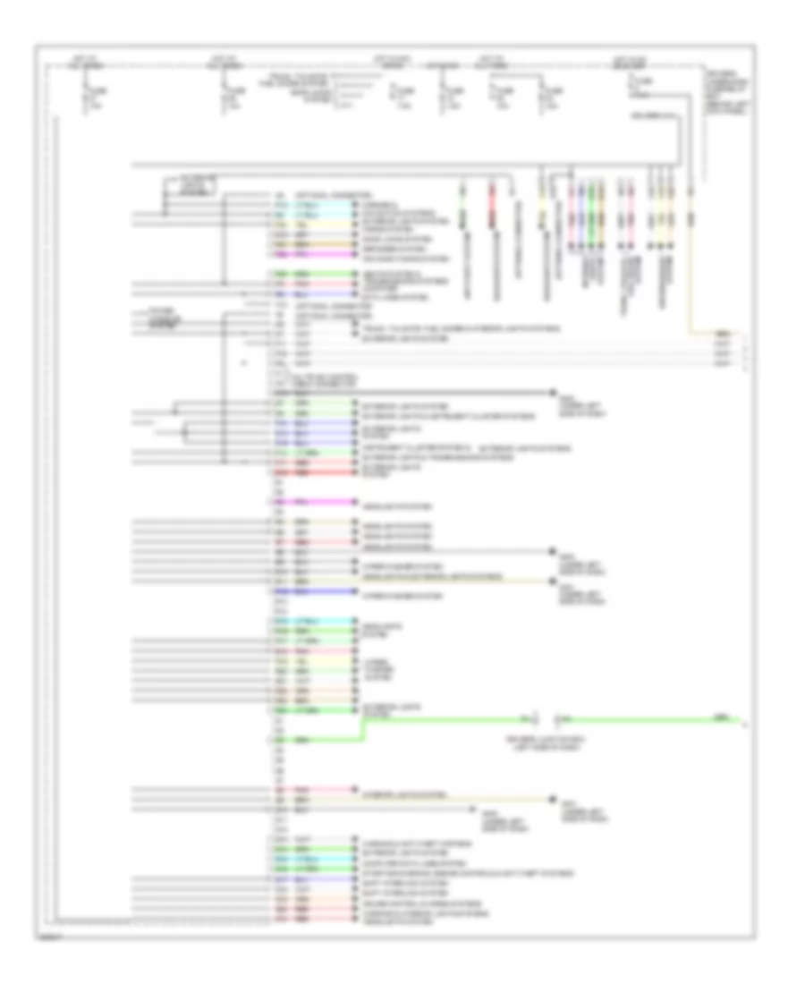
Body Control Modules Wiring Diagram (1 of 2) for Honda Crosstour EX 2012
 https://portal-diagnostov.com/license.html
Automotive Electricians Portal FZCO
Automotive Electricians Portal FZCO
https://portal-diagnostov.com/license.html
https://portal-diagnostov.com/license.html
Automotive Electricians Portal FZCO
Automotive Electricians Portal FZCOList of elements for Body Control Modules Wiring Diagram (1 of 2) for Honda Crosstour EX 2012:
- (optional connector)
- Air conditioning system
- Anti-theft system
- Computer data lines system
- Cruise control & horns systems
- D10
- D12
- D14
- D15
- D16
- Data lines system
- Defogger system
- Door locks system
- Driver's junction box (left side of dash)
- Driver's micu
- Driver's under-dash fuse/relay box (behind left kick panel)
- Exterior lights & instrument cluster systems
- Exterior lights & transmissions systems
- Exterior lights system
- Exterior lights systems
- F10
- F11
- F13
- F14
- F16
- F17
- F18
- F19
- F20
- F21
- F22
- F23
- F32
- Fuse 10a
- Fuse 15a
- Fuse 7.5a
- G10
- G401 (under left side of dash)
- G402 (under left side of dash)
- H10
- H12
- Headlights & exterior lights systems
- Headlights system
- Horns system
- Hot at all times
- Hot in acc or on
- Hot in on
- Hot in on or start
- Instrument cluster system &
- Interior
- Interior lights system
- Lights system
- Mirrors & navigation systems exterior lights system
- Multiplex control check connector
- N15
- P12
- P15
- Pnk
- Power windows system
- Q10
- Q11
- Q12
- Q13
- Q14
- Q15
- Q16
- Q17
- Q18
- Q19
- Q20
- R10
- R11
- R12
- R13
- R14
- R15
- R16
- R17
- R18
- R19
- R20
- R21
- R22
- R23
- R24
- Red
- Seats system & transmissions systems computer
- Shift interlock system
- Starting/charging, engine controls & anti-theft systems
- Trunk, tailgate, fuel doors & interior lights systems
- Trunk, tailgate, fuel doors system
- Warning & anti-theft systems
- Warning & interior lights systems
- Wiper/ washer system
- Wiper/washer system
Body Control Modules Wiring Diagram (2 of 2) for Honda Crosstour EX 2012
 https://portal-diagnostov.com/license.html
Automotive Electricians Portal FZCO
Automotive Electricians Portal FZCO
https://portal-diagnostov.com/license.html
https://portal-diagnostov.com/license.html
Automotive Electricians Portal FZCO
Automotive Electricians Portal FZCOList of elements for Body Control Modules Wiring Diagram (2 of 2) for Honda Crosstour EX 2012:
- (left side of dash) driver's junction box
- (not used)
- A15
- A18
- A19
- A21
- A26
- A27
- A28
- A30
- A34
- A38
- Anti-theft system
- Computer data lines system
- D10
- D13
- D14
- D23
- D25
- D26
- Door locks system
- E12
- E14
- E15
- E17
- E18
- Exterior lights system
- Fuse 10a
- Fuse 15 10a
- Fuse 15a
- Fuse 6 7.5a
- Fuse 7 15a
- G203 (behind glove box)
- G405 (behind glove box)
- H24
- H26
- H31
- H35
- H38
- Headlights system
- Hot at all times
- Interior lights system
- Navigation & sound systems
- Navigation system
- Passenger's micu
- Passenger's under-dash fuse/relay box (behind right kick panel)
- Pnk
- Power windows system
- Red
- Sound systems
- System
- Under-hood fuse/relay box (left rear of engine compt)
- W/ handsfree link
- Wiper/washer
- Wiper/washer system
COMPUTER DATA LINES
Data Link Connector Wiring Diagram for Honda Crosstour EX 2012
 https://portal-diagnostov.com/license.html
Automotive Electricians Portal FZCO
Automotive Electricians Portal FZCO
https://portal-diagnostov.com/license.html
https://portal-diagnostov.com/license.html
Automotive Electricians Portal FZCO
Automotive Electricians Portal FZCOList of elements for Data Link Connector Wiring Diagram for Honda Crosstour EX 2012:
- (under right side of cargo area)
- 2.4l
- 3.5l
- A13
- A14
- A32
- A44
- A48
- A49
- Audio unit
- B25
- C202
- C306
- C407
- Center junction box (under left side of dash)
- Dlc (under left side of dash)
- Driver's micu
- Driver's under-dash fuse/relay box (behind left kick panel)
- Engine mount control unit (behind left kick panel)
- F-can hi
- F-can lo
- F30
- F31
- Fuse 15 10a
- G12
- G13
- G401 (under left side of dash)
- G402 (under left side of dash)
- Gauge control module
- H18
- H19
- H21
- H34
- Hot at all times
- Immobilizer keyless control unit (in steering column)
- J/c c505 (behind middle of dash)
- J/c c604 (behind right rear side trim panel)
- K-line
- Navigation unit (if equipped)
- P13
- P14
- Passenger's under-dash fuse/relay box (behind right kick panel)
- Pcm (left front of engine compt)
- Q15
- Red
- Scs
- Srs unit (under middle of dash)
- Tpms control unit (under left side of dash)
- Under-hood fuse/relay box (left rear of engine compt)
- Vsa modulator control unit (right side of engine compt)
- Wen
- Yaw rate- acceleration sensor (under center console)
F-CAN High/Low & B-CAN High/Low Wiring Diagram for Honda Crosstour EX 2012
 https://portal-diagnostov.com/license.html
Automotive Electricians Portal FZCO
Automotive Electricians Portal FZCO
https://portal-diagnostov.com/license.html
https://portal-diagnostov.com/license.html
Automotive Electricians Portal FZCO
Automotive Electricians Portal FZCOList of elements for F-CAN High/Low & B-CAN High/Low Wiring Diagram for Honda Crosstour EX 2012:
- (left side of dash) driver's junction box
- 2.4l
- 3.5l
- A13
- A14
- A21
- A34
- A49 f-can lo a48 f-can hi a46
- Audio unit
- B-can hi
- B-can lo
- B-can low
- B13
- B21
- B22
- B25
- C306
- C403
- C406
- C411
- C452
- C507
- C701
- C801
- C811
- Center junction box (under left side of dash)
- Climate control unit
- Dlc (under left
- Driver's micu
- Driver's under-dash fuse/relay box (behind left kick panel)
- Engine mount control unit (behind left kick panel)
- F-can hi
- F-can lo
- F16
- F30
- F31
- Front passenger's power window switch
- Fuse 10a
- G12
- G13
- G302 (behind left kick panel)
- Gauge control module
- H10
- H18
- H19
- H21
- H34
- Handsfreelink control unit (if equipped) (under left side of dash)
- Hot at all times
- Immobilizer keyless control unit (in steering column)
- J/c c405 (behind front passenger's airbag)
- J/c c604 (behind right rear side trim panel)
- Moon roof control unit/motor (middle of roof)
- Navigation unit (if equipped) (under right side of cargo area)
- P13
- P14
- Passenger's micu
- Passenger's under-dash fuse/relay box (behind right kick panel)
- Pcm (left front of engine compt)
- Pnk
- Power seat control unit (w/ memory) (under driver's seat)
- Power window master switch (door multiplex control unit)
- Q16
- Red
- Side of dash)
- Srs unit (under middle of dash)
- Tpms control unit (under left side of dash)
- Uart
- Under hood fuse/relay box (left rear of engine compt)
- Vsa modulator control unit (right side of engine compt)
- W/ navigation
- Yaw rate- acceleration sensor (under center console)
GA-NET Bus/GA-NET Audio Wiring Diagram for Honda Crosstour EX 2012
 https://portal-diagnostov.com/license.html
Automotive Electricians Portal FZCO
Automotive Electricians Portal FZCO
https://portal-diagnostov.com/license.html
https://portal-diagnostov.com/license.html
Automotive Electricians Portal FZCO
Automotive Electricians Portal FZCOList of elements for GA-NET Bus/GA-NET Audio Wiring Diagram for Honda Crosstour EX 2012:
- A10
- A11
- A12
- Audio l+
- Audio l-
- Audio r+
- Audio r-
- Audio sh
- Audio unit
- C409
- C410
- C508
- E10
- E11
- E12
- Ga +b
- Ga gnd
- Ga on
- Ga sh
- Ga-bus sh
- Ga-bus+
- Ga-bus-
- J/c c501
- J/c c502
- J/c c504 (behind middle of dash)
- Navigation display unit (if equipped)
- Red
- Usb adapter control unit (under rear of center console)
- Xm receiver (w/ navigation) (behind right rear side trim panel)
COOLING FAN
Cooling Fan Wiring Diagram for Honda Crosstour EX 2012
 https://portal-diagnostov.com/license.html
Automotive Electricians Portal FZCO
Automotive Electricians Portal FZCO
https://portal-diagnostov.com/license.html
https://portal-diagnostov.com/license.html
Automotive Electricians Portal FZCO
Automotive Electricians Portal FZCOList of elements for Cooling Fan Wiring Diagram for Honda Crosstour EX 2012:
- 2.4l
- 3.5l
- A/c compressor clutch relay
- A/c condenser fan motor (behind a/c condenser)
- A/c condenser fan relay
- A/c diode a
- A/c diode b
- A/c pressure sensor (right front of engine compt)
- A10
- A17
- A20
- A21
- A34
- A36
- A37
- A40
- A44
- A45
- A48
- A49
- Air conditioning system
- B10
- B11
- B12
- B13
- B24
- B34
- Blower motor relay
- C16
- C32
- Computer data lines system
- Driver's under- dash fuse/
- Ect sensor 1 (left rear of engine)
- Ect sensor 2 (lower left front of engine compt)
- Engine controls system
- F29
- Fan control relay
- Fuse 15a
- Fuse 3-6 30a
- Fuse 3-8 30a
- Fuse 7.5a
- G301 (behind left side of front bumper)
- Hot at all times
- J/c c107 (top of transmission)
- Pcm (left front of engine compt)
- Pgm-fi sub- relay
- Pnk
- Radiator fan motor (lower left front of engine compt)
- Radiator fan relay
- Red
- Relay box (behind left kick panel)
- Relay circuit board
- Under- hood fuse/ relay box (left rear of engine compt)
CRUISE CONTROL
Cruise Control Wiring Diagram (1 of 2) for Honda Crosstour EX 2012
 https://portal-diagnostov.com/license.html
Automotive Electricians Portal FZCO
Automotive Electricians Portal FZCO
https://portal-diagnostov.com/license.html
https://portal-diagnostov.com/license.html
Automotive Electricians Portal FZCO
Automotive Electricians Portal FZCOList of elements for Cruise Control Wiring Diagram (1 of 2) for Honda Crosstour EX 2012:
- 10a stabilizer circuit
- 2.4l
- 3.5l
- A15
- A18
- A19
- A24
- A25
- A26
- A27
- A29
- A35
- A36
- A38
- A42
- A48
- A49
- App sensor (under left side of dash)
- Apsa
- Apsb
- Atpfwd
- B17
- B18
- B26
- B29
- B33
- B34
- B36
- B38
- Bksw
- Bkswnc
- C101
- C106
- C12
- C13
- C14
- C18
- C20
- C21
- C43
- Computer data lines system
- Controller
- Controller area network 5v stabilize circuit/
- Cruise control ind
- Cruise control main switch ind
- Dimming circuit
- Engine controls system
- Etcs control relay
- Etcsm+
- Etcsm-
- Etcsrly
- F-can transceiver
- F-canh
- F-canl
- Fuse 10a
- Fuse 15a
- G101 (right side of engine)
- G101 (top left rear of engine)
- G401 (under left side of dash)
- Gauge control module
- Hot at all times
- Ig1etcs
- J/c c101
- J/c c104 (rear of engine)
- J/c c106 (transmission housing)
- J/c c107 (3.5l) (top of transmission) j/c c103 (2.4l) (left rear of engine)
- Mrly
- Output shaft (counter shaft) speed sensor (on transmission housing)
- Pcm (left front of engine compt)
- Pgm-fi main relay 1
- Pnk
- Red
- Sensor 1
- Sensor 2
- Sg4
- Sg5
- Tan
- Throttle actuator
- Throttle body (3.5l: top rear of engine) (2.4l: left rear of engine)
- Throttle open sensor
- Tpsa
- Tpsb
- Transmission range switch (on transmission)
- Under-hood fuse/relay box (left rear of engine compt)
- Vcc4
- Vcc5
- Warning drive circuit
Cruise Control Wiring Diagram (2 of 2) for Honda Crosstour EX 2012
 https://portal-diagnostov.com/license.html
Automotive Electricians Portal FZCO
Automotive Electricians Portal FZCO
https://portal-diagnostov.com/license.html
https://portal-diagnostov.com/license.html
Automotive Electricians Portal FZCO
Automotive Electricians Portal FZCOList of elements for Cruise Control Wiring Diagram (2 of 2) for Honda Crosstour EX 2012:
- A10
- Brake pedal position switch (under left side of dash)
- C19
- C20
- Cable reel (in steering column)
- Cancel switch
- Cruise control combination switch
- Driver's junction box (left side of dash)
- Driver's micu
- Driver's under-dash fuse/relay box (behind left kick panel)
- Fuse 5 7.5a
- Fuse 7 15a
- Fuse 8 20a
- G401 (under left side of dash)
- Horns system
- Hot at all times
- Hot in on or start
- Interior lights system
- Main switch
- Q19
- Red
- Resume switch
- Set switch
- Under-hood fuse/relay box (left rear of engine compt)
DEFOGGERS
Defoggers Wiring Diagram, with Navigation for Honda Crosstour EX 2012
 https://portal-diagnostov.com/license.html
Automotive Electricians Portal FZCO
Automotive Electricians Portal FZCO
https://portal-diagnostov.com/license.html
https://portal-diagnostov.com/license.html
Automotive Electricians Portal FZCO
Automotive Electricians Portal FZCOList of elements for Defoggers Wiring Diagram, with Navigation for Honda Crosstour EX 2012:
- A15
- B can h
- B can l
- B-can hi
- B-can lo
- B-canh
- B-canl
- Box (under left side of dash)
- Bus-data
- C304
- C407
- C507
- C602
- C652
- C801
- C811
- Center junction
- Climate control unit
- Computer data lines system
- Defogger
- Door multiplex control
- Driver's climate control switch
- Driver's micu
- Driver's under-dash fuse/relay box (behind left kick panel)
- F21
- F29
- Front passenger's power window switch
- Fuse 13 20a
- Fuse 16 7.5a
- Fuse 5 40a
- G401 (under left side of dash)
- G402 (under left side of dash)
- G405 (behind glove box)
- G502 (behind middle of dash)
- G601 (left side of floor)
- G603 (left rear side trim panel)
- Gnd
- Hot at all times
- Hot in on
- Ig2
- Interior lights system
- Junction connector c506 (behind middle of dash)
- Left power mirror
- Lower rear window defogger
- Mir act dr heat sg
- Noise reduction condenser
- P11
- Passenger's climate control switch
- Passenger's under-dash fuse/relay box (behind right kick panel)
- Pnk
- Power distribution system
- Power window master switch
- Rear window defogger relay
- Rear window/ defogger switch
- Red
- Right power mirror
- Rr def rly cl-
- Uart
- Under-hood fuse/relay box (left rear of engine compt)
- Upper rear window defogger
- Window defogger switch ind
Defoggers Wiring Diagram, without Navigation for Honda Crosstour EX 2012
 https://portal-diagnostov.com/license.html
Automotive Electricians Portal FZCO
Automotive Electricians Portal FZCO
https://portal-diagnostov.com/license.html
https://portal-diagnostov.com/license.html
Automotive Electricians Portal FZCO
Automotive Electricians Portal FZCOList of elements for Defoggers Wiring Diagram, without Navigation for Honda Crosstour EX 2012:
- (2.4l)
- (3.5l)
- (behind left kick panel)
- 2.4l
- 3.5l
- B-can hi
- B-can lo
- B-canh
- B-canl
- Box
- C304
- C407
- C602
- C652
- C801
- C811
- Center junction box (under left side of dash)
- Climate control unit
- Computer data lines system
- Defogger
- Door ig2 multiplex control unit
- Driver's micu
- Driver's under-dash fuse/relay
- Driver's under-dash fuse/relay box (behind left kick panel)
- F21
- F29
- Front passenger's power window switch
- Fuse 13 20a
- Fuse 16 7.5a
- Fuse 5 40a
- G401 (under left side of dash)
- G402 (under left side of dash)
- G405 (behind glove box)
- G502 (behind middle of dash)
- G601 (left side of floor)
- G603 (left rear side trim panel)
- Gnd
- Hot at all times
- Hot in on
- Hvac control unit
- Ig2
- J/c c506 (behind middle of dash)
- Left power mirror
- Lower rear window defogger
- Mir act dr heat
- Noise reduction condenser (behind left rear side trim panel)
- P11
- Passenger's under-dash fuse/relay box (behind right kick panel)
- Pnk
- Power distribution system
- Power window master switch
- Rear window defogger relay
- Rear window defogger switch
- Right power mirror
- Rr def rly cl-
- Uart
- Under-hood fuse/relay box (left rear of engine compt)
- Upper rear window defogger
- Window defogger switch indicator
ENGINE PERFORMANCE
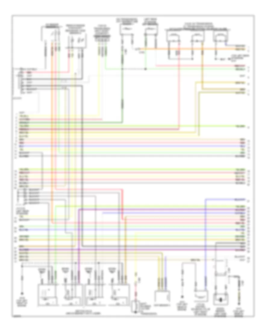
2.4L
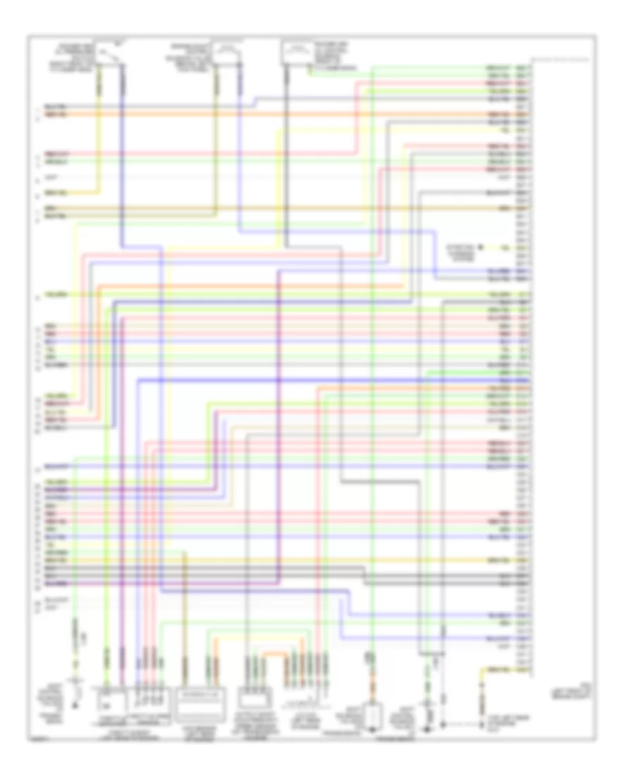
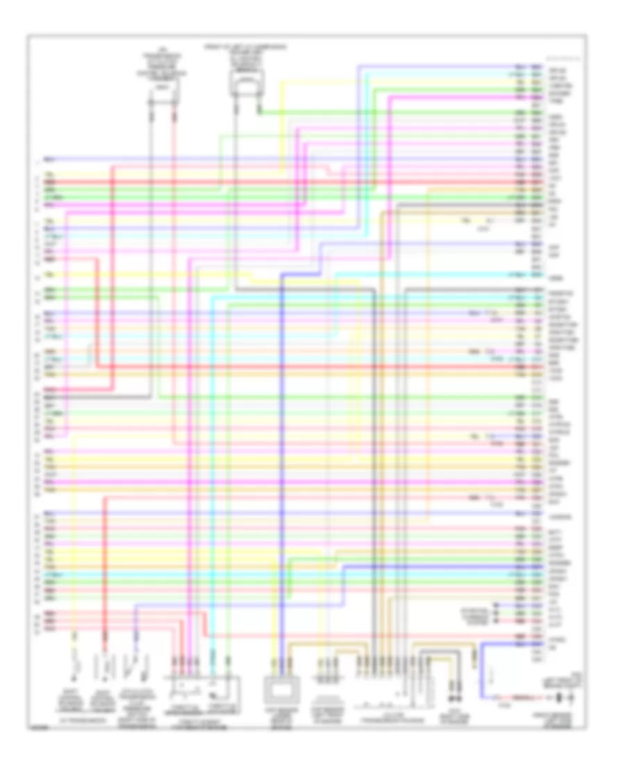
2.4L, Engine Performance Wiring Diagram (1 of 5) for Honda Crosstour EX 2012
 https://portal-diagnostov.com/license.html
Automotive Electricians Portal FZCO
Automotive Electricians Portal FZCO
https://portal-diagnostov.com/license.html
https://portal-diagnostov.com/license.html
Automotive Electricians Portal FZCO
Automotive Electricians Portal FZCOList of elements for 2.4L, Engine Performance Wiring Diagram (1 of 5) for Honda Crosstour EX 2012:
- (top left rear of engine) g101
- A10
- A11
- A12
- A13
- A14
- A15
- A16
- A17
- A18
- A19
- A20
- A21
- A22
- A23
- A24
- A25
- A26
- A27
- A28
- A29
- A30
- A31
- A32
- A33
- A34
- A35
- A36
- A37
- A38
- A39
- A40
- A41
- A42
- A43
- A44
- A45
- A46
- A47
- A48
- A49
- Air conditioning system
- App sensor (under left side of dash)
- App sensor 1
- App sensor 2
- B10
- B11
- B12
- B13
- B14
- B15
- B16
- B17
- B18
- B19
- B20
- B21
- C105
- C106
- Computer data lines system
- Driver's under-dash fuse/relay box (behind left kick panel)
- Driver,s j/b (left side of dash)
- Eld unit
- Etcs control relay
- F15
- Fuse 10 10a
- Fuse 17 15a
- Fuse 18 15a
- G101 (top left rear of engine)
- G302 (behind left kick panel)
- Hot at all times
- Hot in on or start
- J/c c101
- Navigation system
- Oil pressure switch (near oil filter)
- Pcm (left front of engine compt)
- Pgm fi main relay 1
- Pnk
- Red
- Shift lock solinoid (under center console)
- Shift solenoid valve a (in transmission)
- Transmission range switch (on transmission)
- Under- hood fuse/ relay box (left rear of engine compt)
2.4L, Engine Performance Wiring Diagram (2 of 5) for Honda Crosstour EX 2012
 https://portal-diagnostov.com/license.html
Automotive Electricians Portal FZCO
Automotive Electricians Portal FZCO
https://portal-diagnostov.com/license.html
https://portal-diagnostov.com/license.html
Automotive Electricians Portal FZCO
Automotive Electricians Portal FZCOList of elements for 2.4L, Engine Performance Wiring Diagram (2 of 5) for Honda Crosstour EX 2012:
- (lower left front of engine compt) ect sensor 2
- (right front of engine compt) a/c pressure sensor
- (under middle rear of vehicle) evap canister vent shut valve
- (under middle rear of vehicle) ftp sensor
- Brake pedal position switch (under left side of dash)
- C202
- C304
- C306
- Driver's under-dash fuse/relay box (behind left kick panel)
- Evap canister purge valve (right rear of engine)
- Exterior lights system
- F12
- F33
- Fuel gauge sending unit
- Fuel pump
- Fuel tank unit (rear of floor)
- Fuse 7 15a
- Fuse 9 20a
- G203 (behind glove box)
- G602 (left rear of floor)
- Hot in on or start
- Instrument cluster system
- J/c c101
- J/c c103 (left rear of engine)
- Pgm-fi main relay 2
- Pnk
- Power steering pressure switch (psp)
- Red
- Transmission fluid pressure switch a (2nd clutch) (left side of transmission)
- Transmission fluid pressure switch b (3rd clutch) (under transmission housing)
2.4L, Engine Performance Wiring Diagram (3 of 5) for Honda Crosstour EX 2012
 https://portal-diagnostov.com/license.html
Automotive Electricians Portal FZCO
Automotive Electricians Portal FZCO
https://portal-diagnostov.com/license.html
https://portal-diagnostov.com/license.html
Automotive Electricians Portal FZCO
Automotive Electricians Portal FZCOList of elements for 2.4L, Engine Performance Wiring Diagram (3 of 5) for Honda Crosstour EX 2012:
- 5v stabilizer circuit/controller area network controller
- B13
- C104
- C306
- Can-h
- Can-l
- Ckp sensor (under rear of engine)
- Cmp sensor b
- Compulsory turning off circuit
- Compulsory turning on circuit
- Computer data lines system
- Driver's micu
- Driver's under-dash fuse/relay box (behind left kick panel)
- Driver,s j/b (left side of dash)
- F-can transceiver
- Fall safe circuit
- Fuse 11 15a
- Fuse 12 15a
- Fuse 15 10a
- Fuse 4 7.5a
- Fuse 5 7.5a
- G101 (top left rear of engine)
- Gauge control module
- Hot at all times
- Hot in on or start
- Iat
- Ignition coil relay
- Immobilizer keyless control unit (in steering column)
- Injectors (top left side of engine)
- J/c c101
- Maf
- Maf/iat sensor (on intake air box)
- Mil ind
- Pgm fi sub relay
- Pnk
- Q16
- Red
- Relay circuit board
- Under- hood fuse/ relay box (left rear of engine compt)
- Warning drive circuit
2.4L, Engine Performance Wiring Diagram (4 of 5) for Honda Crosstour EX 2012
 https://portal-diagnostov.com/license.html
Automotive Electricians Portal FZCO
Automotive Electricians Portal FZCO
https://portal-diagnostov.com/license.html
https://portal-diagnostov.com/license.html
Automotive Electricians Portal FZCO
Automotive Electricians Portal FZCOList of elements for 2.4L, Engine Performance Wiring Diagram (4 of 5) for Honda Crosstour EX 2012:
- (a & b: on transmission) (c: transmission housing) a/t clutch pressure control solenoid valves
- (left rear of engine) ect sensor 1
- (on transmission) atf temperature sensor
- (rear of engine in exhaust) secondary ho2s (sensor 2)
- (top left rear of engine) g101
- (top of transmission) input shaft (mainshaft) speed sensor
- A/f sensor (sensor 1)
- C105
- C107
- Cmp sensor a
- G101 (top left rear of engine)
- G102 (top left front of engine)
- Icm
- Ignition coils (above respective cylinder)
- J/c c101
- J/c c103 (left rear of engine)
- Knock sensor (left side of engine)
- N/a
- Nca
- Red
- Shift solenoid valve e (in transmission)
- Spark plug
- Vtc oil control solenoid valve (left front of engine)
2.4L, Engine Performance Wiring Diagram (5 of 5) for Honda Crosstour EX 2012
 https://portal-diagnostov.com/license.html
Automotive Electricians Portal FZCO
Automotive Electricians Portal FZCO
https://portal-diagnostov.com/license.html
https://portal-diagnostov.com/license.html
Automotive Electricians Portal FZCO
Automotive Electricians Portal FZCOList of elements for 2.4L, Engine Performance Wiring Diagram (5 of 5) for Honda Crosstour EX 2012:
- (top left rear of engine) g101
- B22
- B23
- B24
- B25
- B26
- B27
- B28
- B29
- B30
- B31
- B32
- B33
- B34
- B35
- B36
- B37
- B38
- B39
- B40
- B41
- B42
- B43
- B44
- B45
- B46
- B47
- B48
- B49
- C10
- C105
- C11
- C12
- C13
- C14
- C15
- C16
- C17
- C18
- C19
- C20
- C21
- C22
- C23
- C24
- C25
- C26
- C27
- C28
- C29
- C30
- C31
- C32
- C33
- C34
- C35
- C36
- C37
- C38
- C39
- C40
- C41
- C42
- C43
- C44
- C45
- C46
- C47
- C48
- C49
- J/c c103 (left rear of engine)
- Map sensor (left rear of engine)
- Output shaft (countershaft) speed sensor (on transmission housing)
- Pcm (left front of engine compt)
- Red
- Rocker arm oil control solenoid (front of cylinder bank)
- Shift control solenoid valve c (in transmission)
- Shift control solenoid valve e (in transmi- ssion)
- Shift solenoid valve b (in transmission)
- Starting/ charging system
- Throttle actuator
- Throttle body (left rear of engine)
- Throttle open sensor
3.5L
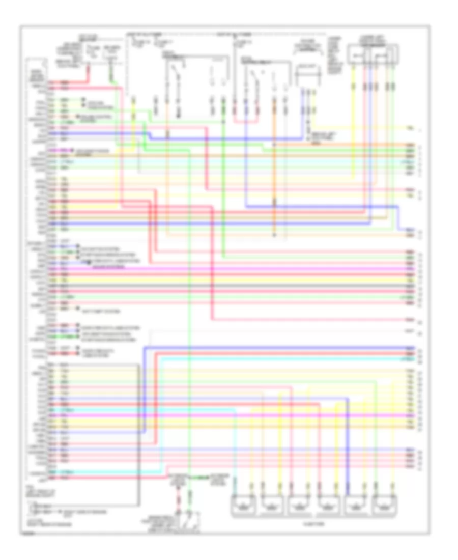
3.5L, Engine Performance Wiring Diagram (1 of 6) for Honda Crosstour EX 2012
 https://portal-diagnostov.com/license.html
Automotive Electricians Portal FZCO
Automotive Electricians Portal FZCO
https://portal-diagnostov.com/license.html
https://portal-diagnostov.com/license.html
Automotive Electricians Portal FZCO
Automotive Electricians Portal FZCOList of elements for 3.5L, Engine Performance Wiring Diagram (1 of 6) for Honda Crosstour EX 2012:
- (behind left kick panel) g302
- (right side of engine) g101
- (under left side of dash) app sensor
- A10
- A11
- A12
- A13
- A14
- A15
- A16
- A17
- A18
- A19
- A20
- A21
- A22
- A23
- A24
- A25
- A26
- A27
- A28
- A29
- A30
- A31
- A32
- A33
- A34
- A35
- A36
- A37
- A38
- A39
- A40
- A41
- A42
- A43
- A44
- A45
- A46
- A47
- A48
- A49
- Acc
- Acpd
- Air conditioning system
- Anti-theft system
- Apsa
- Apsb
- Atp-p
- Atpp
- B10
- B11
- B12
- B13
- B14
- B15
- B16
- B17
- B18
- B19
- B20 vcmswc
- B21
- Baro- meter sensor
- Bksw
- Bkswnc
- Brake pedal position switch (under left side of dash)
- Ckpout
- Cmpout
- Computer data lines system
- Cooling fans system
- Cruise control system
- Cssama
- Cssamc
- Driver's micu
- Driver's under-dash fuse/relay box (behind left kick panel)
- Ect2
- Eld
- Eld unit
- Etcs control relay
- Etcsrly
- Exterior lights system
- F-canh
- F-canl
- F15
- F23
- Fanh
- Fanl
- Ftp
- Fuse 10a
- Fuse 17 15a
- Fuse 18 15a
- Fuse 19 7.5a
- Hot at all times
- Hot in on or start
- Igp
- Igpls5
- Igpls6
- Imofpr
- Inj1
- Inj2
- Inj3
- Inj4
- Inj5
- Inj6
- Injectors
- J/c c105 (right rear of engine)
- Lg3
- Lsb
- Lsc
- Mrly
- Navigation system
- Nep
- Pcm (left front of engine compt)
- Pg2
- Pgm-fi main relay 1
- Pnk
- Power distribution system
- Pspsw
- Red
- S-net5v
- Scs
- Sg3
- Sg4
- Sg7
- Sho2sb2
- Sls
- Sound systems
- Starting/charging system
- Sts
- Subrly
- Tan
- Tpsa
- Under- hood fuse/ relay box (left rear of engine compt)
- Vbsol1
- Vbsol2
- Vbum
- Vcc3
- Vcc4
- Vcc5
- Vcc7
- Vcentb1
- Vg+
- Vg-
- Vsb1
- Vsb2
- Vssout
- Vsv
- Wen
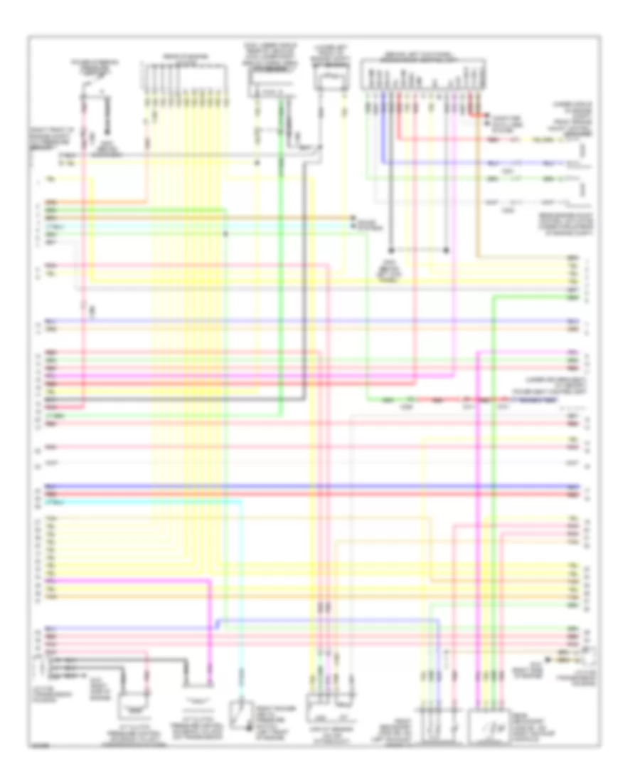
3.5L, Engine Performance Wiring Diagram (2 of 6) for Honda Crosstour EX 2012
 https://portal-diagnostov.com/license.html
Automotive Electricians Portal FZCO
Automotive Electricians Portal FZCO
https://portal-diagnostov.com/license.html
https://portal-diagnostov.com/license.html
Automotive Electricians Portal FZCO
Automotive Electricians Portal FZCOList of elements for 3.5L, Engine Performance Wiring Diagram (2 of 6) for Honda Crosstour EX 2012:
- (2wd: under middle rear of vehicle) (4wd: under right side of cargo area) ftp sensor
- (behind left kick panel) engine mount control unit
- (lower left front of engine compt) ect sensor 2
- (rear of engine) j/c c104
- (right front of engine compt) a/c pressure sensor
- (under driver's seat) (w/ memory) power seat control unit
- (under middle of engine compt) front engine mount control actuator
- A/t clutch pressure control solenoid valve b (on transmission)
- A/t clutch pressure control solenoid valve c (transmission housing)
- B35
- C101
- C202
- C301
- C302
- C304
- C306
- C411
- C701
- Ckp
- Cmp
- Computer data lines system
- F-can h
- F-can l
- Front rocker arm oil pressure switch (left front of engine)
- Front secondary ho2s (b2, s2) (left exhaust manifold)
- G101 (right side of engine)
- G203 (behind glove box)
- G302 (behind left kick panel)
- Iat
- Ig1
- Igsol
- J/c c106 (transmission housing)
- Maf
- Maf/iat sensor (on air intake duct)
- Pnk
- Power steering pressure switch
- Rear engine mount control actuator (under middle rear of engine compt)
- Rear secondary ho2s (b1, s2) (right exhaust manifold)
- Red
- Solfm
- Solfp
- Solrly
- Solrm
- Solrp
- Sound systems
- Tan
3.5L, Engine Performance Wiring Diagram (3 of 6) for Honda Crosstour EX 2012
 https://portal-diagnostov.com/license.html
Automotive Electricians Portal FZCO
Automotive Electricians Portal FZCO
https://portal-diagnostov.com/license.html
https://portal-diagnostov.com/license.html
Automotive Electricians Portal FZCO
Automotive Electricians Portal FZCOList of elements for 3.5L, Engine Performance Wiring Diagram (3 of 6) for Honda Crosstour EX 2012:
- (2wd: under middle rear of vehicle) (4wd: under right side of cargo area) evap canister vent shut valve
- (in left exhaust) front a/f sensor (b2, s1)
- (rear of engine) j/c c104
- (rear of right cylinder bank)
- Acm control relay
- C101
- C304
- C306
- C402
- C411
- Driver's junction box (left side of dash)
- Driver's under-dash fuse/relay box (behind left kick panel)
- Evap canister purge valve (right rear of engine)
- F12
- F33
- Fuel tank unit (2wd: rear of floor) (4wd: top of fuel tank)
- Fuse 14 10a
- Fuse 5 7.5a
- Fuse 7 15a
- Fuse 9 20a
- G101 (right side of engine)
- G602 (left rear of floor)
- Hot at all times
- Hot in on or start
- Instrument cluster system
- J/c c105 (right rear of engine)
- J/c c106 (transmission housing)
- Pgm-fi main relay 2
- Pnk
- Rear a/f sensor (b1, s1)
- Red
- Rocker arm oil control solenoid a (bank 1)
- Rocker arm oil control solenoid b (bank 1)
- Shift lock solenoid (under center console)
- Tan
- W/ navigation
3.5L, Engine Performance Wiring Diagram (4 of 6) for Honda Crosstour EX 2012
 https://portal-diagnostov.com/license.html
Automotive Electricians Portal FZCO
Automotive Electricians Portal FZCO
https://portal-diagnostov.com/license.html
https://portal-diagnostov.com/license.html
Automotive Electricians Portal FZCO
Automotive Electricians Portal FZCOList of elements for 3.5L, Engine Performance Wiring Diagram (4 of 6) for Honda Crosstour EX 2012:
- 5v stabilizer circuit/controller area network controller
- A/t gear position dimming circuit
- A/t gear position indicator drive circuit
- Air
- C101
- Compulsory turning off circuit
- Compulsory turning on circuit
- Computer data lines system
- Conditioning
- Fall safe circuit
- Fast controller area network transceiver
- Fuse 11 15a
- Fuse 12 15a
- Fuse 15 10a
- Fuse 7.5a
- G101 (right side of engine)
- G402 (under left side of dash)
- Gauge control module
- Hot at all times
- Icm
- Ignition coil relay
- Ignition coils
- J/c c104 (right rear of engine)
- J/c c105 (right rear of engine)
- J/c c106 (transmission housing)
- Mil ind
- Pgm-fi sub relay
- Pnk
- Rear rocker arm oil pressure switch (rear of of right cylinder bank)
- Red
- Spark plug
- System
- Tan
- Under- hood fuse/ relay box (left rear of engine compt)
- Warning drive circuit
3.5L, Engine Performance Wiring Diagram (5 of 6) for Honda Crosstour EX 2012
 https://portal-diagnostov.com/license.html
Automotive Electricians Portal FZCO
Automotive Electricians Portal FZCO
https://portal-diagnostov.com/license.html
https://portal-diagnostov.com/license.html
Automotive Electricians Portal FZCO
Automotive Electricians Portal FZCOList of elements for 3.5L, Engine Performance Wiring Diagram (5 of 6) for Honda Crosstour EX 2012:
- (in transmission)
- (left rear of engine) ect sensor 1
- (left rear of engine) egr valve & egr valve position sensor
- (left side of transmission housing) input shaft (mainshaft) speed sensor
- (near oil filter) oil pressure switch
- (on transmission) atf temperature sensor
- (top of transmission) j/c c107
- (transmission housing) j/c c106
- 2nd clutch transmission fluid pressure switch a (left side of transmission)
- 3rd clutch transmission fluid pressure switch b (under transmission housing)
- C101
- C102
- G101 (right side of engine)
- G101 (top left rear of engine)
- J/c c106 (transmission housing)
- J/c c107 (top of trans- mission)
- Map sensor (right rear of engine)
- Output shaft (countershaft) speed sensor (on transmission housing)
- Pnk
- Red
- Shift control solenoid valve b
- Shift control solenoid valve c
- Starting/ charging system
- Tan
- Transmission range switch (on transmission)
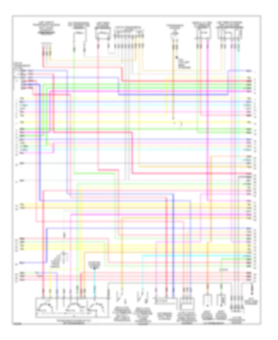
3.5L, Engine Performance Wiring Diagram (6 of 6) for Honda Crosstour EX 2012
 https://portal-diagnostov.com/license.html
Automotive Electricians Portal FZCO
Automotive Electricians Portal FZCO
https://portal-diagnostov.com/license.html
https://portal-diagnostov.com/license.html
Automotive Electricians Portal FZCO
Automotive Electricians Portal FZCOList of elements for 3.5L, Engine Performance Wiring Diagram (6 of 6) for Honda Crosstour EX 2012:
- (front of left cylinder bank) rocker arm oil control solenoid a (bank 2)
- (in transmission)
- (on transmission) a/t clutch pressure control solenoid valve a
- 4th clutch transmission fluid pressure switch (right side of transmission)
- Afshtcb1
- Afshtcb2
- Altc
- Altf
- Altl
- Atft
- Atp21
- Atpd
- Atpd3
- Atpfwd
- Atpn
- Atpr
- Atprvs
- B22
- B23
- B24
- B25
- B26
- B27
- B28
- B29
- B30
- B31
- B32
- B33
- B34
- B35
- B36
- B37
- B38
- B39
- B40
- B41
- B42
- B43
- B44
- B45
- B46
- B47
- B48
- B49
- C10
- C101
- C102
- C103
- C11
- C12
- C13
- C14
- C15
- C16
- C17
- C18
- C19
- C20
- C21
- C22
- C23
- C24
- C25
- C26
- C27
- C28
- C29
- C30
- C31
- C32
- C33
- C34
- C35
- C36
- C37
- C38
- C39
- C40
- C41
- C42
- C43
- C44
- C45
- C46
- C47
- C48
- C49
- Ckp
- Ckp sensor (under rear of engine)
- Cmp
- Cmp sensor (left front of engine)
- Cssa
- Cssb
- Cssc
- Ect1
- Egr
- Egrp
- Etcsm+
- Etcsm-
- G101 (right side of engine)
- Iat
- Ig1
- Ig1etcs
- Igpls1
- Igpls2
- Igpls3
- Igpls4
- Ipb1
- Ipb2
- J/c c106 (transmission housing)
- Knock sensor (left side of engine)
- Lg1
- Lg2
- Lsa
- Map
- Op2sw
- Op3sw
- Op4sw
- Pcm (left front of engine compt)
- Pcs
- Pg1
- Pgmetcs
- Pnk
- Poil
- Red
- S02sgb1
- S02sgb2
- Sg1
- Sg2
- Sg5
- Sg6
- Sha
- Shb
- Shc
- Shd
- Shift control solenoid valve a
- Shift control solenoid valve d
- Sho2sb1
- So2shtcb1
- So2shtcb2
- Starting/ charging system
- Tan
- Throttle actuator
- Throttle body (top rear of engine)
- Throttle open sensor
- Tpsb
- Vcc1
- Vcc2
- Vcc6
- Vcentb2
- Vcmswb
EXTERIOR LIGHTS
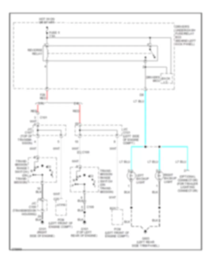
Backup Lamps Wiring Diagram for Honda Crosstour EX 2012
 https://portal-diagnostov.com/license.html
Automotive Electricians Portal FZCO
Automotive Electricians Portal FZCO
https://portal-diagnostov.com/license.html
https://portal-diagnostov.com/license.html
Automotive Electricians Portal FZCO
Automotive Electricians Portal FZCOList of elements for Backup Lamps Wiring Diagram for Honda Crosstour EX 2012:
- (optional connector) (for trailer lighting connector)
- 2.4l
- 3.5l
- Atpr
- B15
- Back lt-
- C101
- C106
- C25
- Driver's micu
- Driver's under-dash fuse/relay box (behind left kick panel)
- F28 red
- Fuse 5 7.5a
- G101 (right side of engine)
- G101 (top left rear of engine)
- G603 (left rear side trim panel)
- Hot in on or start
- J/c c101 (left side of engine compt)
- J/c c106 (transmission housing)
- J/c c107 (top of transmi- ssion)
- Left backup light
- Pcm (left front of engine compt)
- Red
- Reverse relay
- Right backup light
- Trans- mission range switch (on trans- mission)
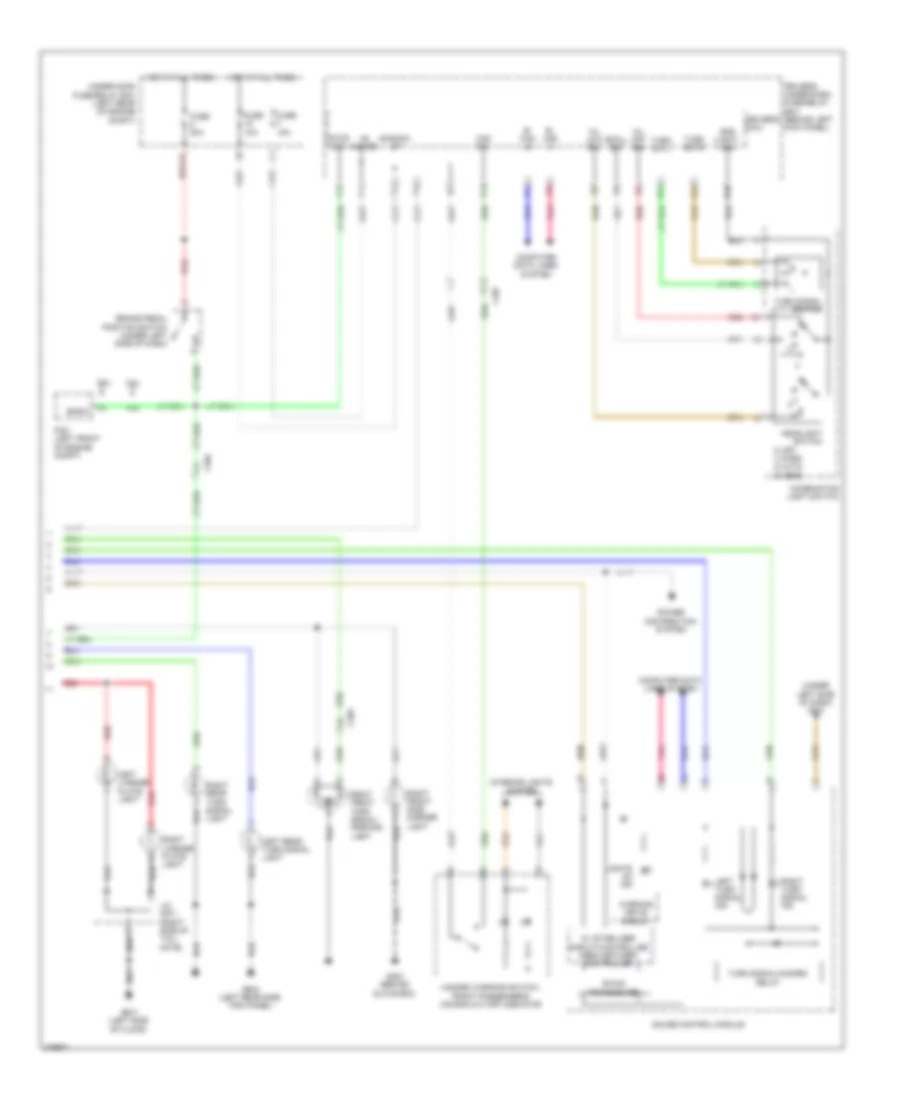
Exterior Lamps Wiring Diagram (1 of 2) for Honda Crosstour EX 2012
 https://portal-diagnostov.com/license.html
Automotive Electricians Portal FZCO
Automotive Electricians Portal FZCO
https://portal-diagnostov.com/license.html
https://portal-diagnostov.com/license.html
Automotive Electricians Portal FZCO
Automotive Electricians Portal FZCOList of elements for Exterior Lamps Wiring Diagram (1 of 2) for Honda Crosstour EX 2012:
- (left side of dash) driver's junction box
- (optional connector) (for trailer lighting connector)
- +b back up
- A18
- A21
- A28
- A34
- Auto lt sid
- Auto lt sig
- Auto lt sip
- Automatic lighting sensor
- Automatic lighting sensor/sunlight sensor (top middle of dash)
- B- can hi
- B- can lo
- C601
- C651
- Computer data lines system
- D10
- D13
- D14
- D16
- D25
- Driver's micu
- Driver's under- dash fuse/ relay box (behind left kick panel)
- E10
- E14
- E15
- E18
- F10
- F17
- Fuse 10a
- Fuse 7.5a
- G203 (behind glove box)
- G301 (behind left side of front bumper)
- G401 (under left side of dash)
- G402 (under left side of dash)
- G601 (left side of floor)
- G603 (left rear side trim panel)
- Gnd (micu-p)
- Gnd (micu-s)
- High mount brake light
- Hot at all times
- Hot in on
- Hot in on or start
- Ig1 day lt
- Ig1 meter
- Left brake light/ taillight
- Left front side marker light
- Left front turn signal/ parking light
- Micu p- gnd
- Micu s- gnd
- P15
- Passenger's micu
- Passenger's under-dash fuse/relay box (behind right kick panel)
- Pnk
- Power distribution system
- Q10
- R11
- Red
- Right brake light/ taillight
Exterior Lamps Wiring Diagram (2 of 2) for Honda Crosstour EX 2012
 https://portal-diagnostov.com/license.html
Automotive Electricians Portal FZCO
Automotive Electricians Portal FZCO
https://portal-diagnostov.com/license.html
https://portal-diagnostov.com/license.html
Automotive Electricians Portal FZCO
Automotive Electricians Portal FZCOList of elements for Exterior Lamps Wiring Diagram (2 of 2) for Honda Crosstour EX 2012:
- (under left side of dash) g401
- +b back- up
- +b hazard
- 0) off 1) park 2) auto 3) head
- 2.4l
- 3.5l
- 5v stabilizer circuit/controller area network controller
- A42
- B- can hi
- B- can lo
- B-can transceiver
- Bksw
- Brake pedal position switch (under left side of dash)
- C202
- C304
- C407
- Combination light switch
- Computer data lines system
- Driver's micu
- Driver's under-dash fuse/relay box (behind left kick panel)
- F11
- F14
- F16
- Front passenger's air bag cut-off indicator
- Fuse 10a
- Fuse 15a
- Fuse 20a
- G203 (behind glove box)
- G601 (left side of floor)
- G603 (left rear side trim panel)
- Gauge control module
- Gnd (light- ing)
- H/l low sw
- H/l off sw
- Haz sw
- Hazard warning switch/
- Headlight switch
- Hot at all times
- Interior lights system
- J/c c671 (right side of tail- gate)
- Left license plate light
- Left rear turn signal light
- Left turn signal ind
- Lights on ind
- Pcm (left front of engine compt)
- Pnk
- Power distribution system
- Q14
- R10
- R23
- R24
- Red
- Right front side marker light
- Right front turn signal/ parking light
- Right license plate light
- Right rear turn signal light
- Right turn signal ind
- Small sw
- Stop sw
- Turn signal switch
- Turn signal/hazard relay
- Turn sw l
- Turn sw r
- Under-hood fuse/relay box (left rear of engine compt)
- Warning drive circuit
GROUND DISTRIBUTION
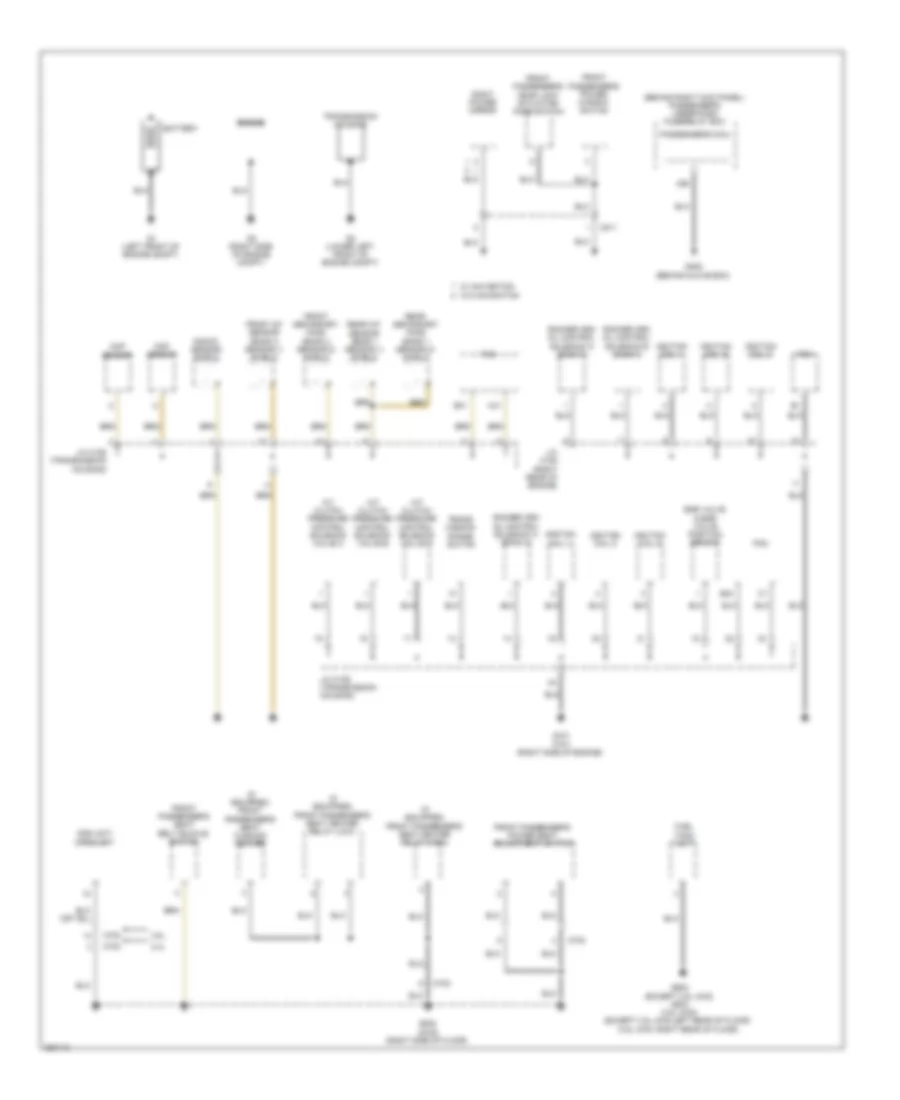
Ground Distribution Wiring Diagram (1 of 5) for Honda Crosstour EX 2012
 https://portal-diagnostov.com/license.html
Automotive Electricians Portal FZCO
Automotive Electricians Portal FZCO
https://portal-diagnostov.com/license.html
https://portal-diagnostov.com/license.html
Automotive Electricians Portal FZCO
Automotive Electricians Portal FZCOList of elements for Ground Distribution Wiring Diagram (1 of 5) for Honda Crosstour EX 2012:
- (behind right kick panel) passenger's under-dash fuse/relay box
- (if equipped) front passenger's seat cushion heater
- (if equipped) front passenger's seat heater relay (high)
- (if equipped) front passenger's seat heater relay (low)
- 2.4l
- 3.5l
- A/t clutch pressure control solenoid valve a
- A/t clutch pressure control solenoid valve b
- A/t clutch pressure control solenoid valve c
- A26
- B40
- B41
- Battery
- C41
- C702
- C811
- Ckp sensor
- Cmp sensor
- Egr valve & egr valve position sensor
- Engine
- Front a/f sensor (bank 2 sensor 1) shield
- Front passenger's door lock actuator/ knob switch
- Front passenger's power seat adjustment switch
- Front passenger's power window switch
- Front passenger's seat belt buckle switch
- Front secondary ho2s (bank 2 sensor 2) shield
- Fuel tank unit
- G1 (left front of engine compt)
- G101 (3.5l) (right side of engine)
- G2 (right side of engine compt)
- G3 (lower left front of engine compt)
- G405 (behind glove box)
- G602 (except 3.5l 4wd) g803 (3.5l 4wd) (except 3.5l 4wd:left rear of floor) (3.5l 4wd: right rear of floor)
- G802 (2wd) (right side of floor)
- Ignition coil 1
- Ignition coil 2
- Ignition coil 3
- Ignition coil 4
- Ignition coil 5
- Ignition coil 6
- J/c c105 (right rear of engine)
- J/c c106 (transmission housing)
- Knock sensor shield
- Ods unit/ opds unit
- Passenger's micu
- Pcm
- Rear a/f sensor (bank 1 sensor 1) shield
- Rear secondary ho2s (bank 1 sensor 2) shield
- Right power mirror
- Rocker arm oil control solenoid a (bank 1)
- Rocker arm oil control solenoid a (bank 2)
- Rocker arm oil control solenoid b (bank 1)
- Trans- mission range switch
- Transmission housing
- W/ navigation
- W/o navigation
Ground Distribution Wiring Diagram (2 of 5) for Honda Crosstour EX 2012
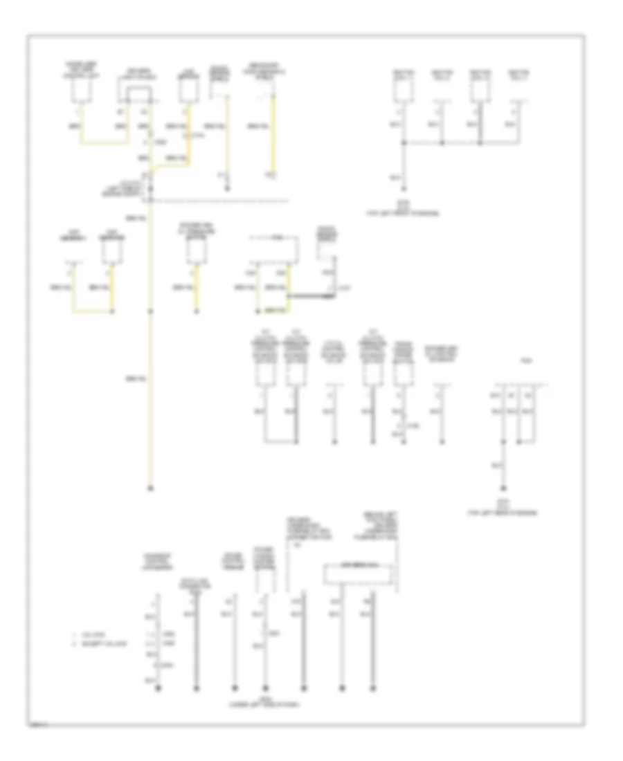 https://portal-diagnostov.com/license.html
Automotive Electricians Portal FZCO
Automotive Electricians Portal FZCO
https://portal-diagnostov.com/license.html
https://portal-diagnostov.com/license.html
Automotive Electricians Portal FZCO
Automotive Electricians Portal FZCOList of elements for Ground Distribution Wiring Diagram (2 of 5) for Honda Crosstour EX 2012:
- (behind left kick panel) driver's under-dash fuse/relay box
- 3.5l 2wd
- A/t clutch pressure control solenoid valve a
- A/t clutch pressure control solenoid valve b
- A/t clutch pressure control solenoid valve c
- B10
- C104
- C106
- C107
- C306
- C35
- C404
- C452
- C49
- C801
- Ckp sensor
- Cmp sensor a
- Cmp sensor b
- Data link connector (dlc)
- Driver's junction box
- Driver's micu
- Driver's under-dash fuse/relay box connector k(3p)
- Except 3.5l 2wd
- G101 (2.4l) (top left rear of engine)
- G102 (2.4l) (top left front of engine)
- G402 (under left side of dash)
- Gauge control module
- Ignition coil 1
- Ignition coil 2
- Ignition coil 3
- Ignition coil 4
- Immobilizer keyless control unit
- J/c c101 (left side of engine compt)
- Knock sensor shield
- Moonroof control unit/motor
- N15
- Nca
- Pcm
- Power window master switch
- Q10
- Rocker arm oil control solenoid
- Rocker arm oil pressure switch
- Secondary ho2s (sensor 2) shield
- Trans- mission range switch
- Vtc oil control solenoid valve
Ground Distribution Wiring Diagram (3 of 5) for Honda Crosstour EX 2012
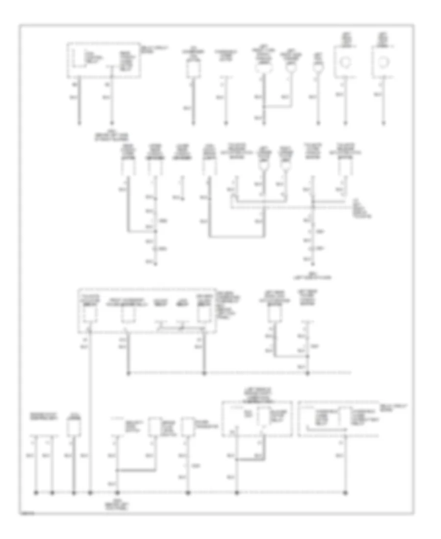 https://portal-diagnostov.com/license.html
Automotive Electricians Portal FZCO
Automotive Electricians Portal FZCO
https://portal-diagnostov.com/license.html
https://portal-diagnostov.com/license.html
Automotive Electricians Portal FZCO
Automotive Electricians Portal FZCOList of elements for Ground Distribution Wiring Diagram (3 of 5) for Honda Crosstour EX 2012:
- (2.4l) diode
- (left rear of engine compt) under-hood fuse/relay box
- A/c condenser fan motor
- Blower motor relay
- Brake fluid level switch
- C303
- C601
- C602
- C651
- C652
- C821
- D13
- Driver's under-dash fuse/relay box (behind left kick panel)
- Driver's unlock relay
- Eld unit
- Engine mount control unit
- Fan control relay
- Front accessory power socket relay
- G301 (behind left side of front bumper)
- G302 (behind left kick panel)
- G601 (left side of floor)
- High mount brake light
- J/c c671 (right side of tailgate)
- Left fog light
- Left front side marker light
- Left front turn signal/ parking light
- Left head light (high)
- Left head light (low)
- Left license plate light
- Left rear door lock actuator/knob switch
- Left rear power window switch
- Lock relay
- Lower rear window defogger
- Power transistor
- Rear window wiper motor
- Rear window wiper motor relay
- Relay circuit board
- Right license plate light
- Security hood switch
- Tailgate actuator relay
- Tailgate outer handle switch
- Tailgate release actuator/latch switch
- Unlock relay
- Upper rear window defogger
- Windshield wiper intermittent relay
- Windshield wiper motor
- Windshield wiper motor relay
Ground Distribution Wiring Diagram (4 of 5) for Honda Crosstour EX 2012
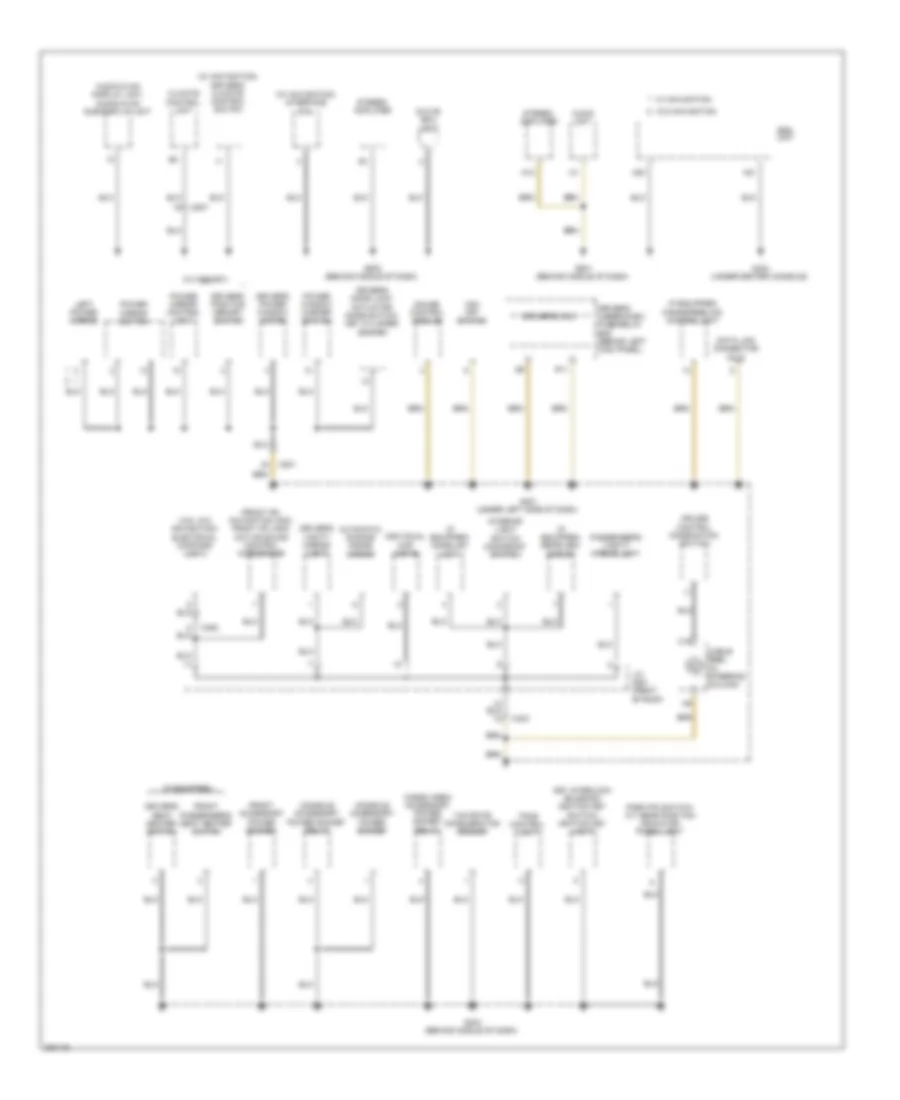 https://portal-diagnostov.com/license.html
Automotive Electricians Portal FZCO
Automotive Electricians Portal FZCO
https://portal-diagnostov.com/license.html
https://portal-diagnostov.com/license.html
Automotive Electricians Portal FZCO
Automotive Electricians Portal FZCOList of elements for Ground Distribution Wiring Diagram (4 of 5) for Honda Crosstour EX 2012:
- (3.5l w/o navigation) electrical compass unit
- (front hfl navigation anc) front hfl-anc/ active sound control microphone
- (if equipped)
- (if equipped) handsfreelink control unit
- (if equipped) homelink unit
- (if equipped) rearview mirror
- (w/ memory)
- (w/ navigation) driver's climate control switch
- (w/ navigation) interface dial
- A12
- A20
- A21
- Audio unit
- Audio-hvac display unit, audio-hvac sub-display unit
- Automatic dimming inside mirror
- C19
- C403
- C452
- C507
- C801
- Cable reel (in steering column)
- Cargo area accessory power socket relay
- Climate control unit
- Console accessory power socket
- Console accessory power socket relay
- Cruise control combination switch
- Data link connector (dlc)
- Driver's door lock actuator/ knob switch/ key cylinder switch
- Driver's micu
- Driver's position memory switch
- Driver's power window motor
- Driver's seat heater switch
- Driver's under-dash fuse/relay box (behind left kick panel)
- Driver's vanity mirror light
- Front accessory power socket
- Front passenger's seat heater switch
- G401 (under left side of dash)
- G403 (behind middle of dash)
- G404 (under center console)
- G501 (behind middle of dash)
- G502 (behind middle of dash)
- Gauge control module
- Glove box light
- Individual map lights
- Interior light switch (moonroof switch)
- J/c c451 (front of roof)
- Key interlock solenoid/ ignition key switch/ ignition key light
- Left power mirror
- Park pin switch/ a/t gear position indicator panel light
- Passenger's vanity mirror light
- Power mirror control unit
- Power mirror switch
- Power window master switch
- R11
- Srs unit
- Stereo amplifier
- Tpms control unit
- Vsa off switch
- W/ navigation
- W/o navigation
- Yaw rate acceleration sensor
Ground Distribution Wiring Diagram (5 of 5) for Honda Crosstour EX 2012
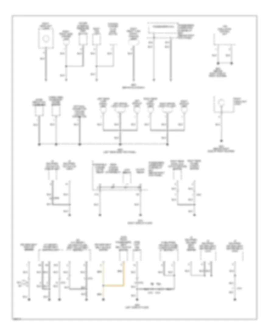 https://portal-diagnostov.com/license.html
Automotive Electricians Portal FZCO
Automotive Electricians Portal FZCO
https://portal-diagnostov.com/license.html
https://portal-diagnostov.com/license.html
Automotive Electricians Portal FZCO
Automotive Electricians Portal FZCOList of elements for Ground Distribution Wiring Diagram (5 of 5) for Honda Crosstour EX 2012:
- (4wd) front passenger's seat belt buckle switch
- (canada) washer fluid level switch
- (ex w/o memory) driver's power seat adjustment switch
- (if equipped) driver's power lumbar support switch
- (if equipped) driver's seat back heater
- (if equipped) driver's seat heater relay (high)
- (if equipped) driver's seat heater relay (low)
- (if equipped) navigation display unit
- (if equipped) navigation unit
- (optional connector (trailer lighting connector)
- (w/ memory) power seat control unit
- B12
- C509
- C701
- C702
- C831
- Cargo area accessory power socket
- Driver's seat belt buckle switch
- Driver's seat position sensor
- E14
- E15
- Ex-l
- G201 (behind right side of front bumper)
- G202 (behind right side of front bumper)
- G203 (behind glove box)
- G603 (left rear side trim panel)
- G701 (right side of floor)
- G801 (left side of floor)
- H12
- Left backup light
- Left brake light/taillight
- Left rear turn signal light
- Lock relay
- Noise reduction condenser
- Ods unit
- Opds unit/
- Passenger's micu
- Passenger's under-dash fuse/relay box (behind right kick panel)
- Power steering pressure (psp) switch
- Rear window washer motor relay
- Right backup light
- Right brake light/taillight
- Right fog light
- Right front side marker light
- Right front turn signal/ parking light
- Right headlight (high)
- Right headlight (low)
- Right rear door lock actuator/knob switch
- Right rear power window switch
- Right rear turn signal light
- Unlock relay
- Vsa modulator- control unit
- Windshield washer motor relay
HEADLIGHTS
Headlights Wiring Diagram (1 of 2) for Honda Crosstour EX 2012
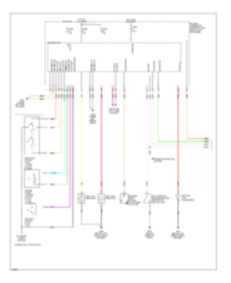 https://portal-diagnostov.com/license.html
Automotive Electricians Portal FZCO
Automotive Electricians Portal FZCO
https://portal-diagnostov.com/license.html
https://portal-diagnostov.com/license.html
Automotive Electricians Portal FZCO
Automotive Electricians Portal FZCOList of elements for Headlights Wiring Diagram (1 of 2) for Honda Crosstour EX 2012:
- +b backup
- B-can hi
- B-can lo
- Backup h/l
- Combination light switch
- Computer data lines system
- D15
- Day lt ig2
- Dimmer sw
- Dimmer/ flash- to-pass switch 0) low 1) high 2) passing
- Driver's door switch (at driver's "b" pillar)
- Driver's micu
- Driver's under-dash fuse/relay box (behind left kick panel)
- Exterior lights system
- F13
- F16
- Fog light switch 0) off 1) on
- Fr door sw l
- Fr fog lt
- Fr fog sw
- Fuse 10a
- Fuse 15a
- Fuse 7.5a
- G10
- G301 (behind left side of front bumper)
- G401 (under left side of dash)
- G402 (under left side of dash)
- G403 (behind middle of dash)
- Gnd (lighting)
- Gnd (micu-p)
- Gnd (micu-s)
- H/l low sw
- H/l off sw
- Headlight switch 0) off 1) park 2) auto 3) head
- Hot at all times
- Hot in on
- Hot in on or start
- Ig1 meter
- Key interlock solenoid/ignition key switch/ ignition light
- Key sw
- Left fog light (if equipped)
- Left high headlight
- Left low headlight
- Passing sw
- Pnk
- Power distribution system
- Q10
- Q13
- R10
- R11
- R15
- R16
- Red
- Small sw
Headlights Wiring Diagram (2 of 2) for Honda Crosstour EX 2012
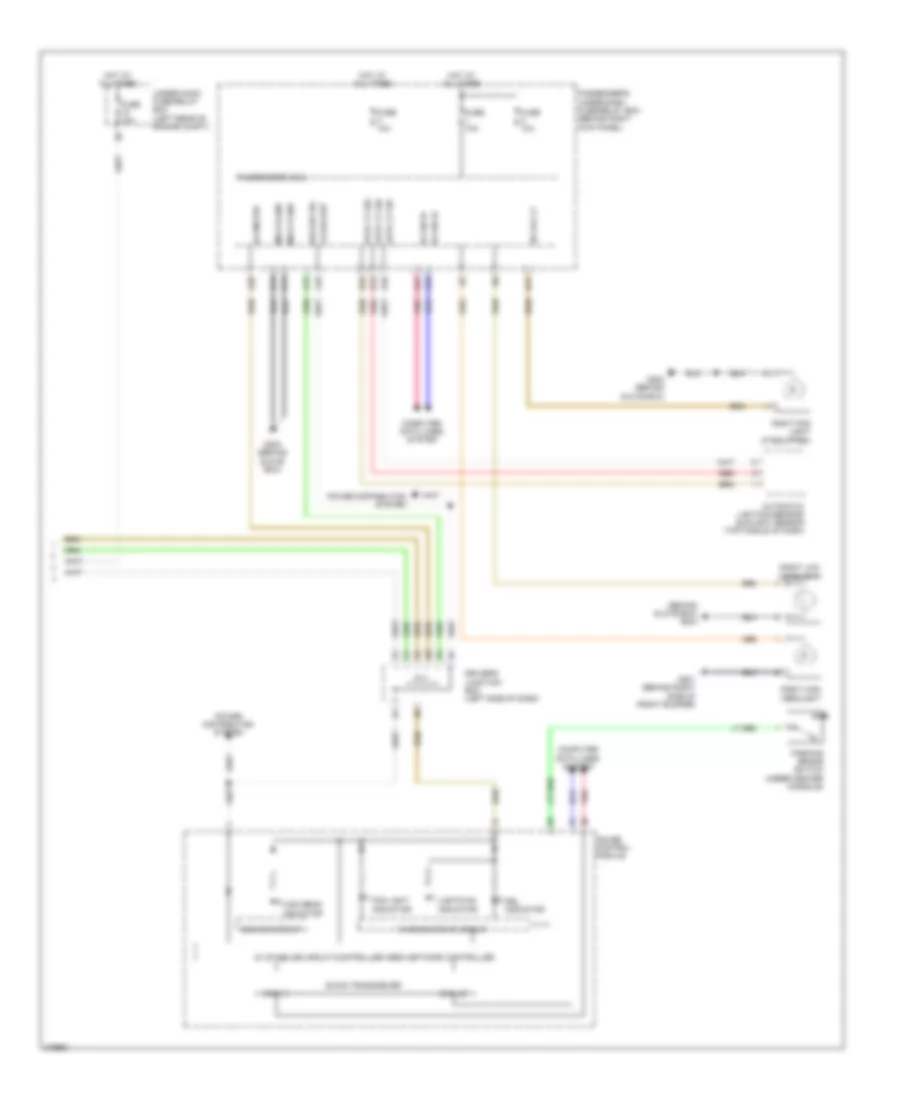 https://portal-diagnostov.com/license.html
Automotive Electricians Portal FZCO
Automotive Electricians Portal FZCO
https://portal-diagnostov.com/license.html
https://portal-diagnostov.com/license.html
Automotive Electricians Portal FZCO
Automotive Electricians Portal FZCOList of elements for Headlights Wiring Diagram (2 of 2) for Honda Crosstour EX 2012:
- (behind glove box) g203
- +b backup
- 5v stabilize circuit/controller area network controller
- A15
- A18
- A21
- A28
- A34
- Auto lt sid
- Auto lt sig
- Auto lt sip
- Automatic lighting sensor/ sunlight sensor (top middle of dash)
- B-can hi
- B-can lo
- B-can transceiver
- Backup h/l
- Can hi
- Can lo
- Computer data lines system
- D10
- D13
- D25
- Dimming circuit
- Driver's junction box (left side of dash)
- Drl indicator
- E14
- E15
- E17
- Fog light indicator
- Fuse 10a
- G201 (behind right side of front bumper)
- G203 (behind glove box)
- Gauge control module
- High beam indicator
- Hot at all times
- Ig1 meter
- Lights on indicator
- Micu p-gnd
- Micu s-gnd
- Parking brake switch (under center console)
- Passenger's micu
- Passenger's under-dash fuse/relay box (behind right kick panel)
- Pnk
- Power distribution system
- Red
- Right fog light (if equipped)
- Right high headlight
- Right low headlight
- Rr fog lt
- Under-hood fuse/relay box (left rear of engine compt)
- Warning drive circuit
HORN
Horn Wiring Diagram for Honda Crosstour EX 2012
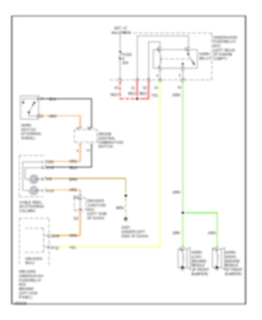 https://portal-diagnostov.com/license.html
Automotive Electricians Portal FZCO
Automotive Electricians Portal FZCO
https://portal-diagnostov.com/license.html
https://portal-diagnostov.com/license.html
Automotive Electricians Portal FZCO
Automotive Electricians Portal FZCOList of elements for Horn Wiring Diagram for Honda Crosstour EX 2012:
- A10
- C19
- C20
- Cable reel (in steering column)
- Cruise control combination switch
- Driver's junction box (left side of dash)
- Driver's micu
- Driver's under-dash fuse/relay box (behind left kick panel)
- F32
- Fuse 20a
- G401 (under left side of dash)
- Horn (high) (behind middle of front bumper)
- Horn (low) (behind middle of front bumper)
- Horn relay
- Horn switch (steering wheel)
- Hot at all times
- Q19
- Red
- Under-hood fuse/relay box (left rear of engine compt)
INSTRUMENT CLUSTER
Instrument Cluster Wiring Diagram (1 of 2) for Honda Crosstour EX 2012
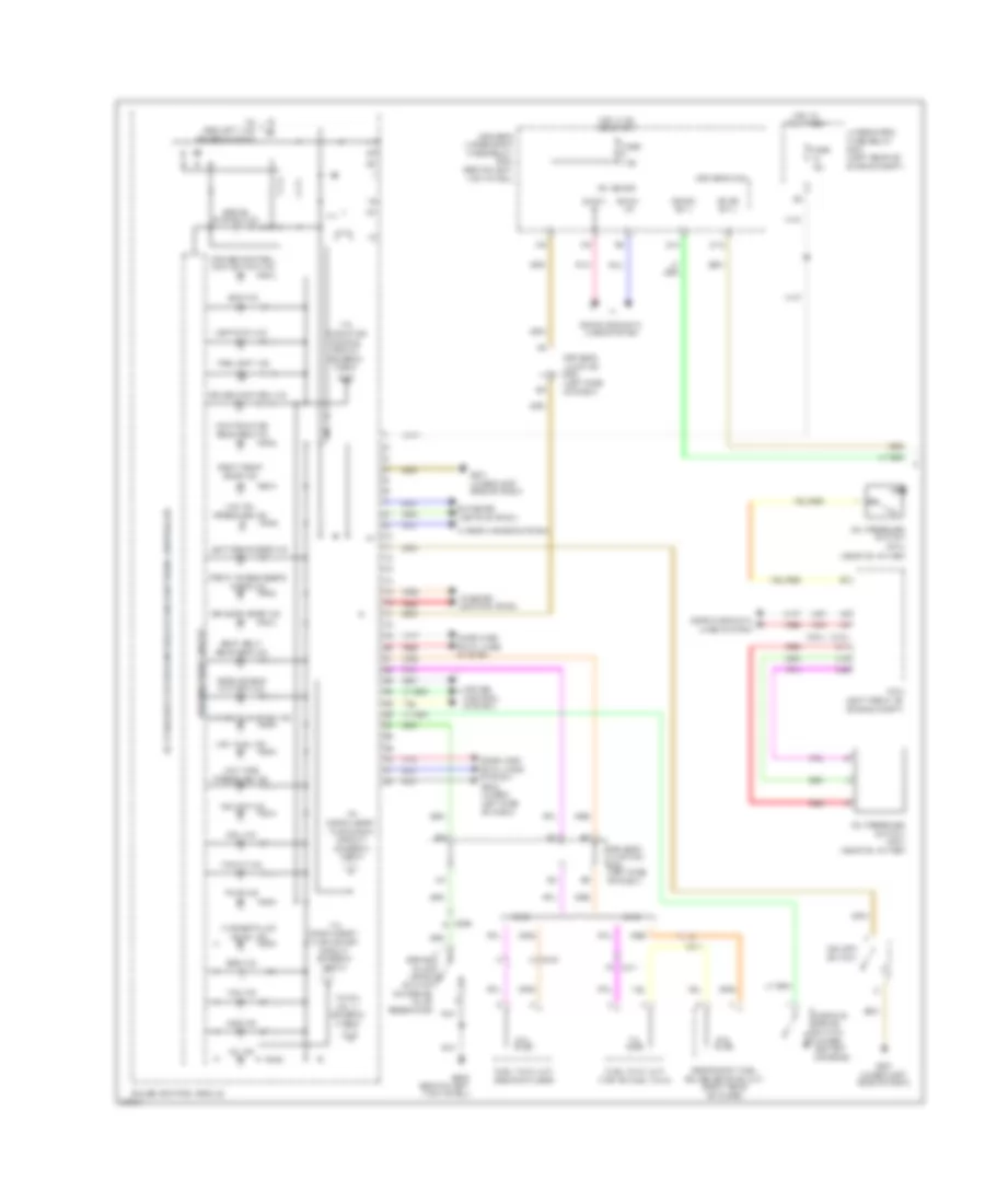 https://portal-diagnostov.com/license.html
Automotive Electricians Portal FZCO
Automotive Electricians Portal FZCO
https://portal-diagnostov.com/license.html
https://portal-diagnostov.com/license.html
Automotive Electricians Portal FZCO
Automotive Electricians Portal FZCOList of elements for Instrument Cluster Wiring Diagram (1 of 2) for Honda Crosstour EX 2012:
- (2.4l)
- (3.5l)
- (near oil filter)
- 2wd
- 4wd
- 5v stabilizer circuit/controller area network controller
- A48
- A49
- Abs ind
- B-can hi
- B-can lo
- Brake fluid level switch (on brake fluid reservoir)
- Brake system ind
- C11
- C15
- C22
- C306
- C401
- C411
- Charging system ind
- Computer data lines system
- Cruise control ind
- Cruise control main switch ind
- Cruise control system
- D10
- D15
- Driver's door ind
- Driver's junction box (left side of dash)
- Driver's micu
- Driver's under-dash fuse/relay box (behind left kick panel)
- Drl ind
- Eco ind
- Exterior lights system
- Fog light ind
- Fr dr sw l
- Front passenger's door ind
- Fuel tank unit (rear of floor)
- Fuel tank unit (top of fuel tank)
- Fuse 10a
- Fuse 7.5a
- G302 (behind left kick panel)
- G401 (under left side of dash)
- G402 (under left side of dash)
- Gauge control module
- Hot at all times
- Hot in on or start
- Ig1 meter
- Interior lights system
- Left rear door ind
- Lights on ind
- Low fuel ind
- Low oil pressure ind
- Low tire pressure ind
- Maintenance
- Mil ind
- Oil pressure switch (2.4l)
- Oil pressure switch (3.5l) (near oil filter)
- Parking brake switch (under center console)
- Pcm (left front of engine compt)
- Pnk
- Red
- Required ind
- Right rear door ind
- Rr dr sw l
- Seat belt reminder ind
- Secondary fuel gauge sending unit (right rear of floor)
- Side air bag cut-off ind
- Srs ind
- To compulsory turning off circuit (diagram 2 of 2)
- To compulsory turning on circuit (diagram 2 of 2)
- To indicator dimming circuit (diagram 2 of 2)
- To pin no. 17 (diagram 2 of 2)
- To security ind (diagram 2 of 2)
- Tpms ind
- Trunk ind
- Under-hood fuse/relay box (left rear of engine compt)
- Vsa ind
- Vsa off ind
- Vsa off switch
- Warning drive circuit
- Washer fluid level ind
- Wiper/washer system
Instrument Cluster Wiring Diagram (2 of 2) for Honda Crosstour EX 2012
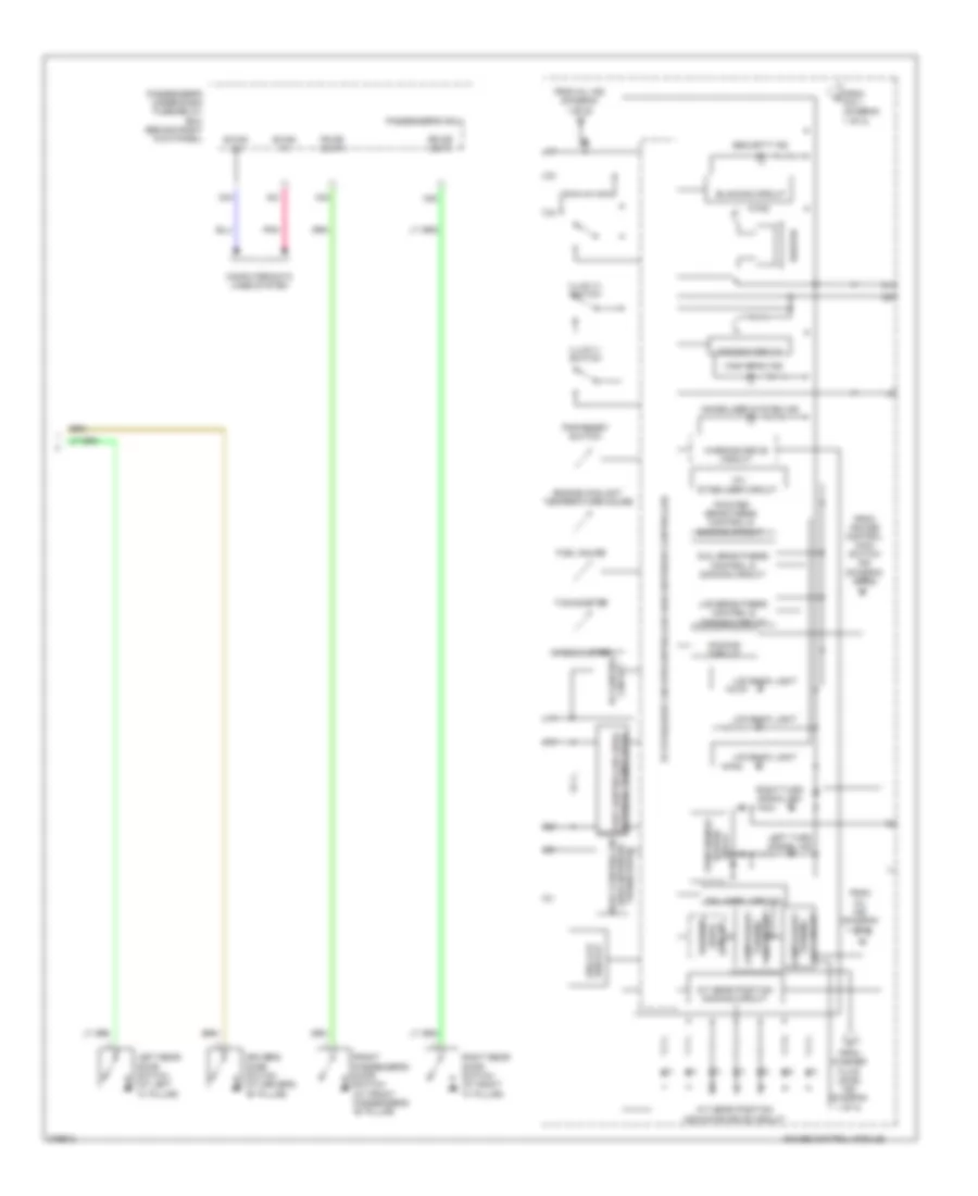 https://portal-diagnostov.com/license.html
Automotive Electricians Portal FZCO
Automotive Electricians Portal FZCO
https://portal-diagnostov.com/license.html
https://portal-diagnostov.com/license.html
Automotive Electricians Portal FZCO
Automotive Electricians Portal FZCOList of elements for Instrument Cluster Wiring Diagram (2 of 2) for Honda Crosstour EX 2012:
- -off circuit turning
- 10v stabilizer circuit
- 5v stabilizer circuit/controller area network controller
- A/t gear position dimming circuit
- A/t gear position indicator drive circuit
- A21
- A34
- B-can hi
- B-can lo
- Beeper
- Blinking circuit
- Body controller area network transceiver
- Circuit
- Circuit 5v control
- Compulsory
- Computer data lines system
- Dial brightness control & dimming circuit
- Dimming circuit
- Display seg lcd
- Drive warning
- Driver's door switch (at driver's "b" pillar)
- Engine coolant temperature gauge
- Fail-safe
- Fr dr sw r
- From cruise control main switch ind (diagram 1 of 2)
- From mil ind (diagram 1 of 2)
- From pin 1 (diagram 1 of 2)
- From washer fluid level ind (diagram 1 of 2)
- Front passenger's door switch (at front passenger's "b" pillar)
- Fuel gauge
- Gauge control module
- H24
- H35
- High beam ind
- Illum (+) switch
- Illum (-) switch
- Immobilizer system ind
- Lcd back light
- Lcd brightness control & dimming circuit
- Left rear door switch (at left "c" pillar)
- Left turn signal ind
- Network transceiver fast controller area
- Passenger's micu
- Passenger's under-dash fuse/relay box (behind right kick panel)
- Pnk
- Pointer brightness control & dimming circuit
- Relay hazard turn signal/
- Right rear door switch (at right "c" pillar)
- Right turn signal ind
- Rr dr sw r
- Security ind
- Speedometer
- Tachometer
- Trip/reset switch
- Turning -on circuit
- Warning drive circuit
INTERIOR LIGHTS
Courtesy Lamps Wiring Diagram for Honda Crosstour EX 2012
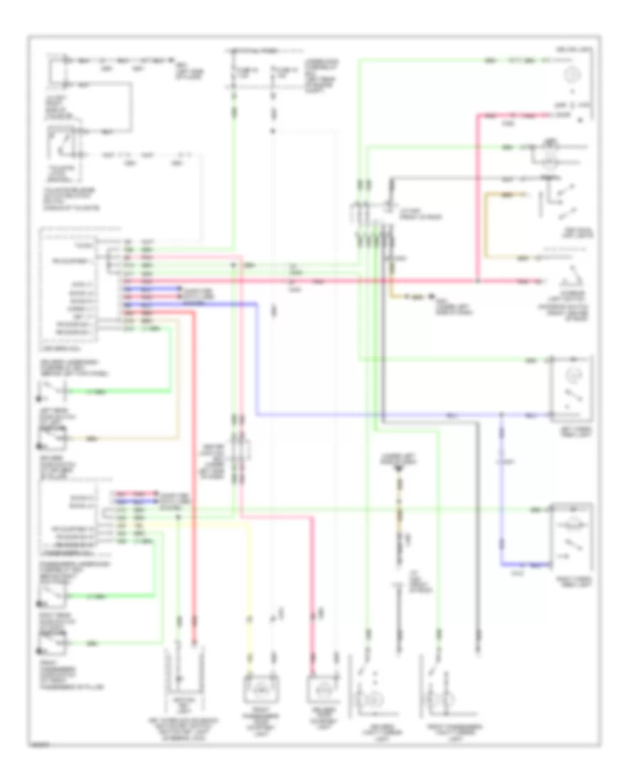 https://portal-diagnostov.com/license.html
Automotive Electricians Portal FZCO
Automotive Electricians Portal FZCO
https://portal-diagnostov.com/license.html
https://portal-diagnostov.com/license.html
Automotive Electricians Portal FZCO
Automotive Electricians Portal FZCOList of elements for Courtesy Lamps Wiring Diagram for Honda Crosstour EX 2012:
- (under left side of dash) g401
- A21
- A22
- A30
- A34
- B-can hi
- B-can lo
- C401
- C403
- C412
- C452
- C601
- C651
- C801
- C811
- Cargo lt
- Ceiling light
- Center junction box (under left side of dash)
- Computer data lines system
- D10
- D11
- D15
- Door
- Driver's door courtesy light
- Driver's door switch (at driver's "b" pillar)
- Driver's micu
- Driver's under-dash fuse/relay box (behind left kick panel)
- Driver's vanity mirror light
- F26
- Fr courtesy l
- Fr courtesy r
- Fr door sw l
- Fr door sw r
- Front passenger's door courtesy light
- Front passenger's door switch (at front passenger's "b" pillar)
- Front passenger's vanity mirror light
- Fuse 15 10a
- Fuse 16 7.5a
- G401 (under left side of dash)
- G601 (left side of floor)
- H13
- H24
- H35
- Hot at all times
- Ignition key light
- Individual map lights
- Interior light switch
- Intr lt-
- J/c c451 (front of roof)
- J/c c671 (right side of tailgate)
- Key interlock solenoid/ ignition key switch/ ignition key light (steering lock)
- Key lt-
- Left
- Left cargo area light
- Left rear door switch (at left "c" pillar)
- Moonroof switch (front center of roof)
- Off
- P10
- Passenger's micu
- Passenger's under-dash fuse/relay box (behind right kick panel)
- Pnk
- Q20
- Red
- Right
- Right cargo area light
- Right rear door switch (at right "c" pillar)
- Rr door sw l
- Rr door sw r
- T/g sw
- Tailgate latch switch
- Tailgate release actuator/latch switch (middle of tailgate)
- Under-hood fuse/relay box (left rear of engine compt)
Entry Light Timer Wiring Diagram for Honda Crosstour EX 2012
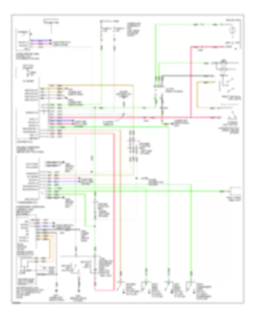 https://portal-diagnostov.com/license.html
Automotive Electricians Portal FZCO
Automotive Electricians Portal FZCO
https://portal-diagnostov.com/license.html
https://portal-diagnostov.com/license.html
Automotive Electricians Portal FZCO
Automotive Electricians Portal FZCOList of elements for Entry Light Timer Wiring Diagram for Honda Crosstour EX 2012:
- (under left side of dash) g401
- +b back up
- +b backup
- A18
- A21
- A22
- A26
- A28
- A34
- Antenna
- B-can hi
- B-can lo
- B-canh
- B-canl
- C403
- C452
- C801
- Ceiling light
- Center junction box (under left side of dash)
- Computer data lines system
- D10
- D15
- Door
- Door control block
- Door lock knob
- Driver's door key cylinder switch
- Driver's door lock actuator/knob switch/ key cylinder switch (on driver's door)
- Driver's door switch (at driver's "b" pillar)
- Driver's junction box (left side of dash)
- Driver's micu
- Driver's under-dash fuse/relay box (behind left kick panel)
- E14
- E15
- F16
- F26
- Fr door sw l
- Fr door sw r
- Front individual map lights
- Front passenger's door switch (at front passenger's "b" pillar)
- Fuse 15 10a
- Fuse 16 7.5a
- Fuse 5 7.5a
- G10
- G203 (behind glove box)
- G401 (under left side of dash)
- G402 (under left side of dash)
- G403 (behind middle of dash)
- G405 (behind glove box)
- Gnd (micu-p)
- Gnd (micu-s)
- H13
- H24
- H35
- Hot at all times
- Hot in on or start
- Ig1 meter
- Ignition key light
- Ignition key switch
- Immobilizer keyless control unit (in steering column)
- Interior light switch
- Intr lt-
- J/c c451 (front of roof)
- Kc dr lk
- Kc dr ul
- Key
- Key interlock solenoid/ igniton key switch/ igniton key light
- Key lt-
- Key sw
- Left
- Left rear door switch (at left "c" pillar)
- Lock
- Micu p-gnd
- Micu s-gnd
- Moonroof switch (front center of roof)
- Off
- P10
- Passenger's micu
- Passenger's under-dash fuse/relay box (behind right kick panel)
- Pnk
- Power distribution system
- Power window master switch
- Q10
- Q13
- Q20
- R11
- Red
- Right
- Right cargo area light
- Right rear door switch (at right "c" pillar)
- Rr door sw l
- Rr door sw r
- Transmitter
- Un- lock
- Under-hood fuse/relay box (left rear of engine compt)
- Vbu
- W/ hands- freelink
Instrument Illumination Wiring Diagram (1 of 3) for Honda Crosstour EX 2012
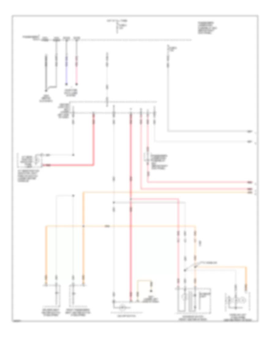 https://portal-diagnostov.com/license.html
Automotive Electricians Portal FZCO
Automotive Electricians Portal FZCO
https://portal-diagnostov.com/license.html
https://portal-diagnostov.com/license.html
Automotive Electricians Portal FZCO
Automotive Electricians Portal FZCOList of elements for Instrument Illumination Wiring Diagram (1 of 3) for Honda Crosstour EX 2012:
- A/t gear position indicator light/ park pin switch (under center console)
- A/t gear position indicator panel light
- A19
- A21
- A33
- A34
- B-can hi
- B-can lo
- C403
- Center junction box (under left side of dash)
- Computer data lines system
- D14
- Driver's seat heater switch (if equipped)
- E14
- E15
- Front passenger's seat heater switch (if equipped)
- Fuse 2 10a
- Fuse 6 7.5a
- G203 (behind glove box)
- G401 (under left side of dash)
- Homelink unit (if equipped) (center front of roof)
- Hot at all times
- Interior light
- K10
- Micu p-gnd
- Micu s-gnd
- Moonroof switch (front center of roof)
- Passenger's micu
- Passenger's under-dash fuse/relay box (behind right kick panel)
- Pnk
- Red
- Vsa off switch
- W/ homelink
Instrument Illumination Wiring Diagram (2 of 3) for Honda Crosstour EX 2012
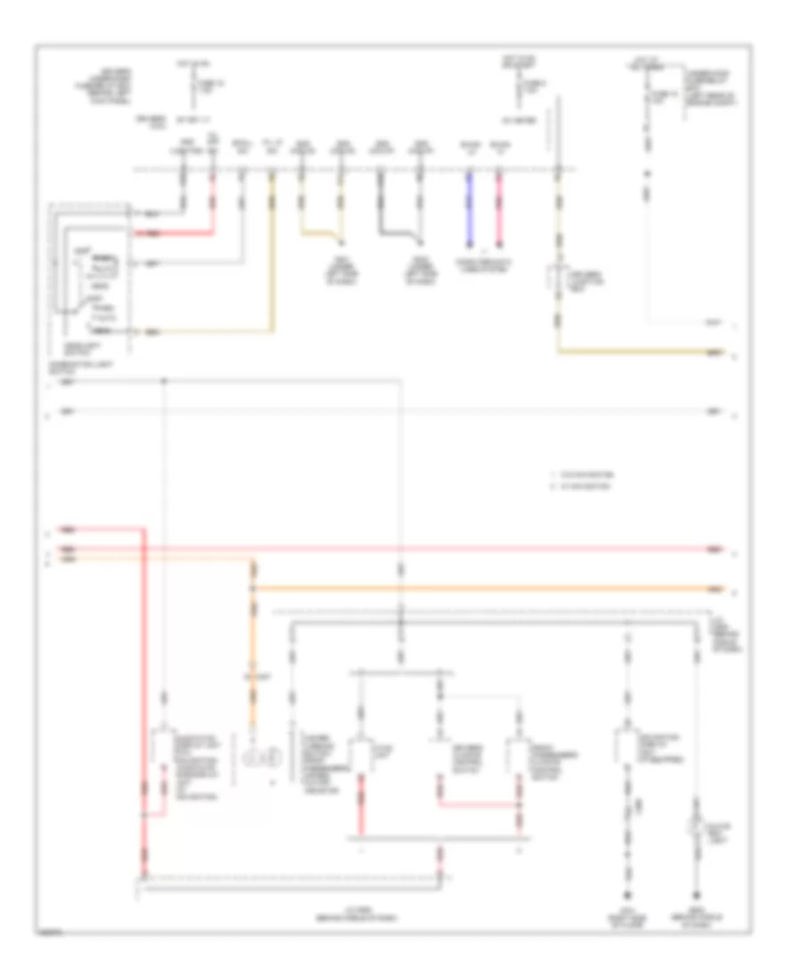 https://portal-diagnostov.com/license.html
Automotive Electricians Portal FZCO
Automotive Electricians Portal FZCO
https://portal-diagnostov.com/license.html
https://portal-diagnostov.com/license.html
Automotive Electricians Portal FZCO
Automotive Electricians Portal FZCOList of elements for Instrument Illumination Wiring Diagram (2 of 3) for Honda Crosstour EX 2012:
- (lighting)
- Audio-hvac display unit (w/o navigation) audio-hvac sub-display unit (w/ navigation)
- Auto
- B-can hi
- B-can lo
- C407
- C509
- Combination light switch
- Computer data lines system
- Driver's climate control switch
- Driver's junction box
- Driver's micu
- Driver's under-dash fuse/relay box (behind left kick panel)
- Front passenger's climate control switch
- Fuse 15 10a
- Fuse 15 7.5a
- Fuse 5 7.5a
- G401 (under left side of dash)
- G402 (under left side of dash)
- G502 (behind middle of dash)
- G701 (right side of floor)
- Glove box light
- Gnd
- Gnd (micu-p)
- Gnd (micu-s)
- H/l lo
- H/l off
- Hazard warning switch/ front passenger's air bag cut-off indicator
- Head
- Headlight switch
- Hot at all times
- Hot in on
- Hot in on or start
- Hvac unit
- Ig1 day lt
- Ig1 meter
- J/c c505 (behind middle of dash)
- J/c c506 (behind middle of dash)
- Navigation display unit (if equipped)
- Off
- Park
- Pnk
- Q10
- R10
- R11
- Red
- Small sw
- Under-hood fuse/relay box (left rear of engine compt)
- W/ navigation
- W/o navigation
Instrument Illumination Wiring Diagram (3 of 3) for Honda Crosstour EX 2012
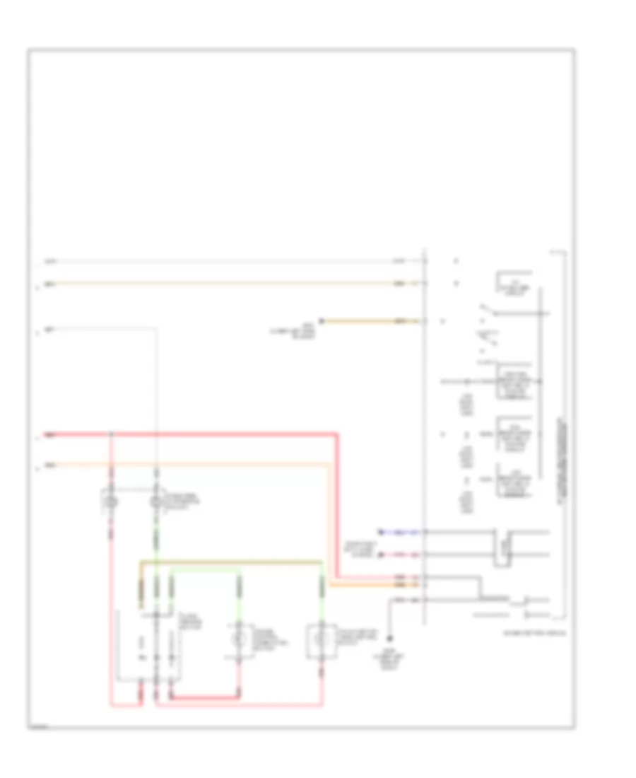 https://portal-diagnostov.com/license.html
Automotive Electricians Portal FZCO
Automotive Electricians Portal FZCO
https://portal-diagnostov.com/license.html
https://portal-diagnostov.com/license.html
Automotive Electricians Portal FZCO
Automotive Electricians Portal FZCOList of elements for Instrument Illumination Wiring Diagram (3 of 3) for Honda Crosstour EX 2012:
- 10v stabilizer circuit
- 5v stabilize circuit/controller area network controller
- Audio remote switch
- Cable reel (in steering column)
- Computer data lines system
- Cruise control combination switch
- Dial brightness control & dimming circuit
- G401 (under left side of dash)
- G402 (under left side of dash)
- Gauge control module
- Hfl-navigation voice control switch
- Illumi (+)
- Illumi (-)
- Lcd back light (led)
- Lcd brightness control & dimming circuit
- Pnk
- Pointer brightness control & dimming circuit
- Red
- Transceiver b-can
MEMORY SYSTEMS
Memory Mirrors Wiring Diagram (1 of 2) for Honda Crosstour EX 2012
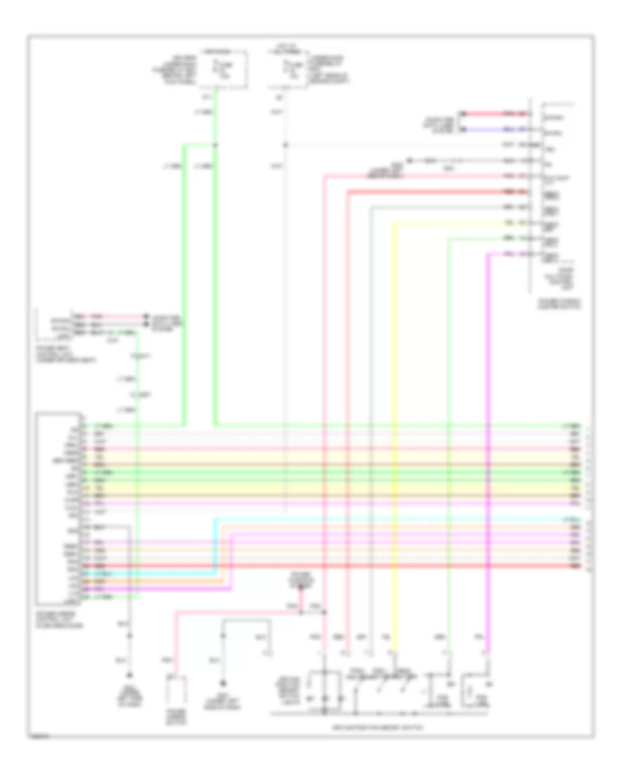 https://portal-diagnostov.com/license.html
Automotive Electricians Portal FZCO
Automotive Electricians Portal FZCO
https://portal-diagnostov.com/license.html
https://portal-diagnostov.com/license.html
Automotive Electricians Portal FZCO
Automotive Electricians Portal FZCOList of elements for Memory Mirrors Wiring Diagram (1 of 2) for Honda Crosstour EX 2012:
- (in driver's door)
- (left rear of engine compt)
- B-canh
- B-canl
- B21
- B22
- B23
- C411
- C701
- C801
- Computer data lines system
- Door multiplex control unit
- Driver's under-dash fuse/relay box (behind left kick panel)
- Driving position memory switch
- Driving position memory switch lights
- Fuse 10a
- Fuse 7.5a
- G401 (under left side of dash)
- G402 (under left side of dash)
- Gnd
- Hot at all times
- Hot in on
- Ig2
- Lhm
- Lmc
- Lseh
- Lsev
- Lvm
- Memo button
- Memo ind 1
- Memo ind 2
- Memo pos 1
- Memo pos 2
- Memo set
- Mldl
- Mldr
- Mrdl
- Mrdr
- Mul
- P/w cont ill+
- P11
- Pnk
- Pos 1 button
- Pos 1 ind
- Pos 2 button
- Pos 2 ind
- Power mirror control unit
- Power mirror switch
- Power seat control unit (under driver's seat)
- Power window master switch
- Power windows system
- Red
- Rhm
- Rmc
- Rseh
- Rsev
- Rvm
- Sen feed
- Uart
- Under-hood fuse/relay box
- Vbu
Memory Mirrors Wiring Diagram (2 of 2) for Honda Crosstour EX 2012
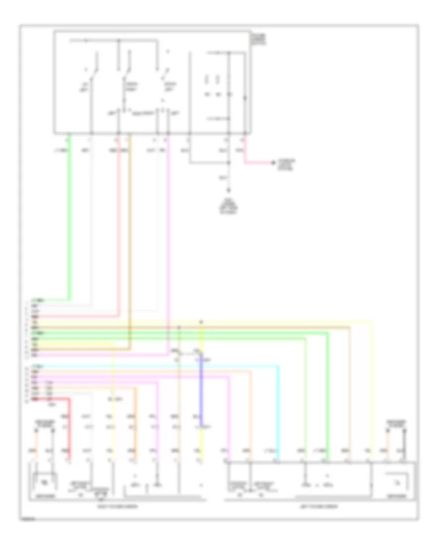 https://portal-diagnostov.com/license.html
Automotive Electricians Portal FZCO
Automotive Electricians Portal FZCO
https://portal-diagnostov.com/license.html
https://portal-diagnostov.com/license.html
Automotive Electricians Portal FZCO
Automotive Electricians Portal FZCOList of elements for Memory Mirrors Wiring Diagram (2 of 2) for Honda Crosstour EX 2012:
- C801
- C811
- Defogger
- Defogger system
- Down/
- G401 (under left side of dash)
- Interior lights system
- Left
- Left power mirror
- Left/right motor
- Pnk
- Power mirror switch
- Red
- Right
- Right power mirror
- Up/
- Up/down motor
Memory Seat Wiring Diagram (1 of 3) for Honda Crosstour EX 2012
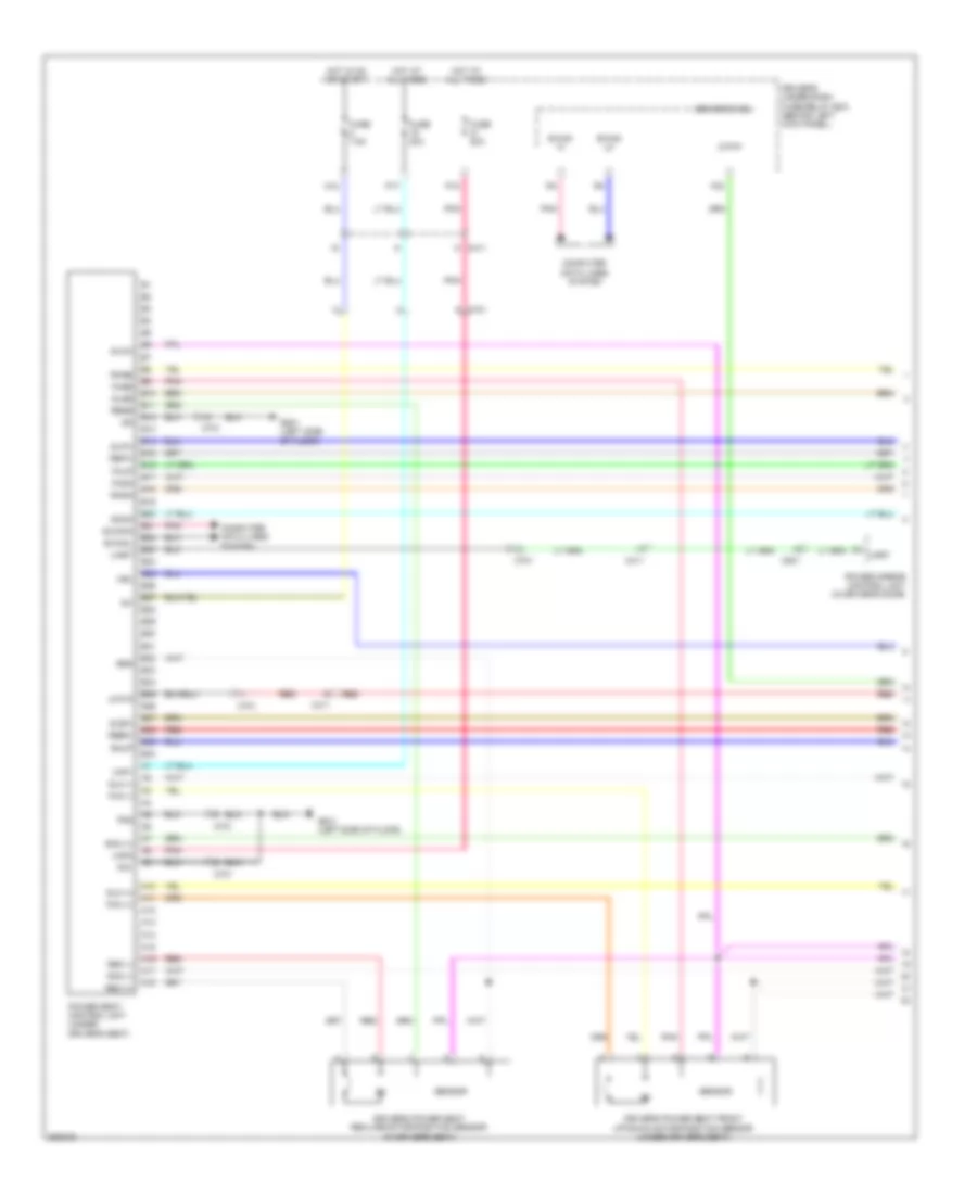 https://portal-diagnostov.com/license.html
Automotive Electricians Portal FZCO
Automotive Electricians Portal FZCO
https://portal-diagnostov.com/license.html
https://portal-diagnostov.com/license.html
Automotive Electricians Portal FZCO
Automotive Electricians Portal FZCOList of elements for Memory Seat Wiring Diagram (1 of 3) for Honda Crosstour EX 2012:
- A10
- A11
- A12
- A13
- A14
- A15
- A16
- A17
- A18
- Atp-p
- B-can hi
- B-can lo
- B-canh
- B-canl
- B10
- B11
- B12
- B13
- B14
- B15
- B16
- B17
- B18
- B19
- B20
- B21
- B22
- B23
- B24
- B25
- B26
- B27
- B28
- B29
- B30
- B31
- B32
- B33
- B34
- B35
- B36
- B37
- B38
- B39
- B40
- C411
- C701
- C801
- Computer data lines system
- Driver's micu
- Driver's power seat front up-down motor/position sensor (under driver's seat)
- Driver's power seat recline motor/position sensor (in driver's seat)
- Driver's under-dash fuse/relay box (behind left kick panel)
- F23
- Fhdn
- Fhm (+)
- Fhm (-)
- Fhse
- Fhup
- Fuse 20a
- Fuse 7.5a
- G801 (left side of floor)
- Hot at all times
- Hot in on or start
- Ig1
- N12
- P17
- P18
- Pg1
- Pg2
- Pnk
- Power mirror control unit (in driver's door)
- Power seat control unit (under driver's seat)
- Rebw
- Red
- Refw
- Rem (+)
- Rem (-)
- Rese
- Rhdn
- Rhm (+)
- Rhm (-)
- Rhse
- Rhup
- Scom
- Seg
- Sensor
- Slbw
- Slfw
- Slm (+)
- Slm (-)
- Slse
- Svcc
- Uart
- Vbu
- Vmp1
- Vmp2
Memory Seat Wiring Diagram (2 of 3) for Honda Crosstour EX 2012
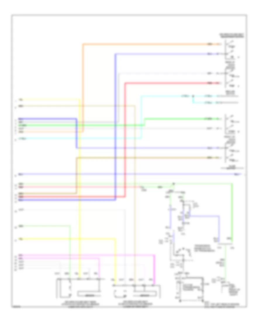 https://portal-diagnostov.com/license.html
Automotive Electricians Portal FZCO
Automotive Electricians Portal FZCO
https://portal-diagnostov.com/license.html
https://portal-diagnostov.com/license.html
Automotive Electricians Portal FZCO
Automotive Electricians Portal FZCOList of elements for Memory Seat Wiring Diagram (2 of 3) for Honda Crosstour EX 2012:
- 2.4l
- 2.4l 3.5l
- 3.5l
- A16
- Atpp
- B14
- Bwd
- C101
- C106
- C306
- Down
- Driver's power seat adjustment switch
- Driver's power seat rear up-down motor/position sensor (under driver's seat)
- Driver's power seat slide motor/position sensor (under driver's seat)
- Front up- down switch
- Fwd
- G101 (2.4l: top left rear of engine) (3.5l: right side of engine)
- J/c c101
- J/c c106 (transmission housing)
- Pcm (left front of engine compt)
- Rear up down switch
- Recline switch
- Red
- Sensor
- Slide switch
- Transmission range switch (on transmission)
Memory Seat Wiring Diagram (3 of 3) for Honda Crosstour EX 2012
 https://portal-diagnostov.com/license.html
Automotive Electricians Portal FZCO
Automotive Electricians Portal FZCO
https://portal-diagnostov.com/license.html
https://portal-diagnostov.com/license.html
Automotive Electricians Portal FZCO
Automotive Electricians Portal FZCOList of elements for Memory Seat Wiring Diagram (3 of 3) for Honda Crosstour EX 2012:
- (in steering column)
- (left rear of engine compt)
- 5v stabilizer circuit/ controller area network controller
- Antenna
- B-can hi
- B-can lo
- B-canh
- B-canl
- Body controller area network transceiver
- C411
- C701
- C801
- Canh
- Canl
- Computer data lines system
- Door multiplex control unit
- Driver's junction box (left side of dash)
- Driving position memory switch
- Driving position memory switch lights
- Fuse 10a
- G401 (under left side of dash)
- G402 (under left side of dash)
- Gauge control module
- Hot at all times
- Immobilizer keyless control unit
- Memo button
- Memo ind 1
- Memo ind 2
- Memo pos 1
- Memo pos 2
- Memo set
- P/w cont ill+
- Pnk
- Pos 1 button
- Pos 1 ind
- Pos 2 button
- Pos 2 ind
- Power mirror switch
- Power window master switch
- Power windows system
- Red
- Transmitter
- Under-hood fuse/relay box
- Vbu
NAVIGATION
Compass Wiring Diagram for Honda Crosstour EX 2012
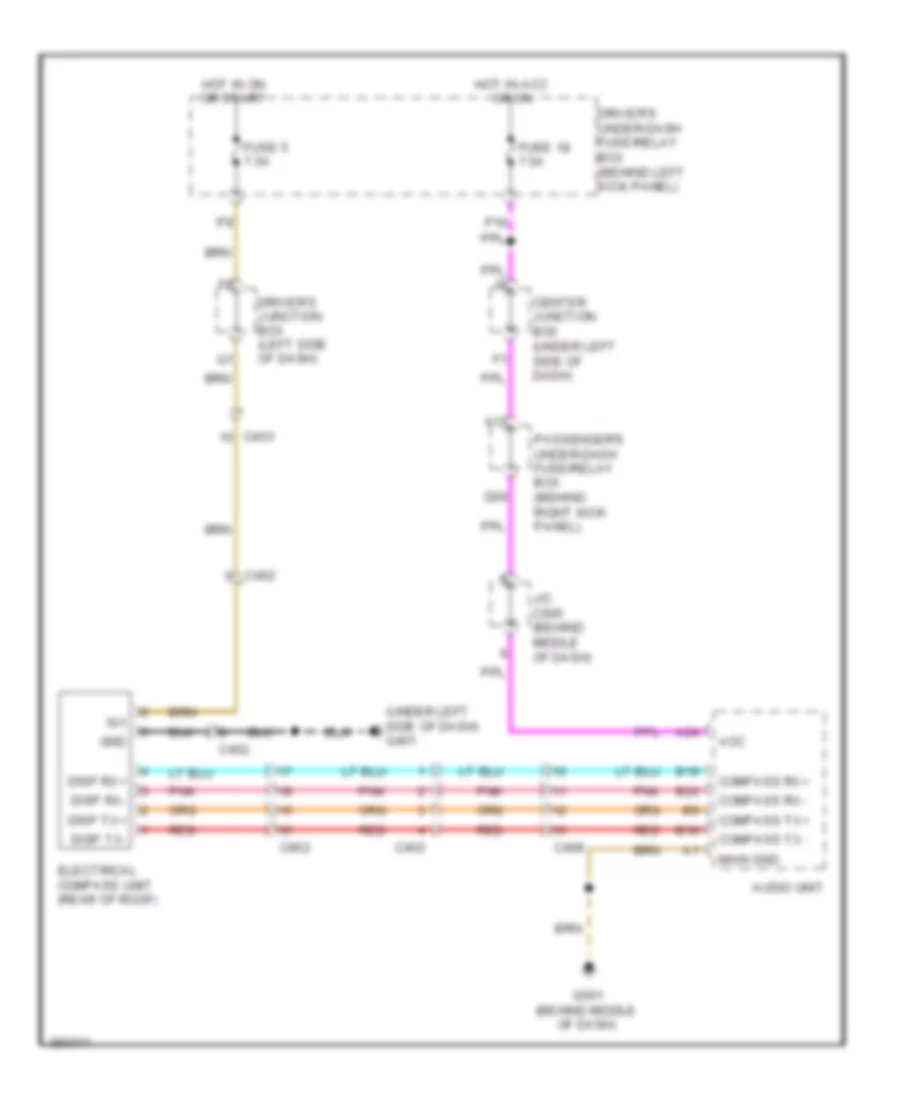 https://portal-diagnostov.com/license.html
Automotive Electricians Portal FZCO
Automotive Electricians Portal FZCO
https://portal-diagnostov.com/license.html
https://portal-diagnostov.com/license.html
Automotive Electricians Portal FZCO
Automotive Electricians Portal FZCOList of elements for Compass Wiring Diagram for Honda Crosstour EX 2012:
- (under left side of dash) g401
- A17
- A24
- Acc
- Audio unit
- B10
- B19
- B20
- C403
- C408
- C452
- Center junction box (under left side of dash)
- Compass rx+
- Compass rx-
- Compass tx+
- Compass tx-
- D24
- Disp rx+
- Disp rx-
- Disp tx+
- Disp tx-
- Driver's junction box (left side of dash)
- Driver's under-dash fuse/relay box (behind left kick panel)
- Electrical compass unit (rear of roof)
- Fuse 18 7.5a
- Fuse 5 7.5a
- G501 (behind middle of dash)
- Gnd
- Hot in acc or on
- Hot in on or start
- Ig1
- J/c c505 (behind middle of dash)
- Main gnd
- P16
- Passenger's under-dash fuse/relay box (behind right kick panel)
- Pnk
- Red
Hands Free Module Wiring Diagram for Honda Crosstour EX 2012
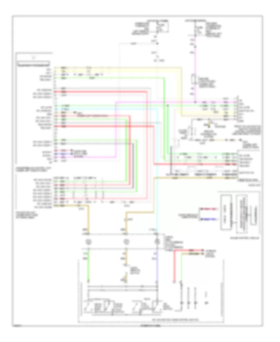 https://portal-diagnostov.com/license.html
Automotive Electricians Portal FZCO
Automotive Electricians Portal FZCO
https://portal-diagnostov.com/license.html
https://portal-diagnostov.com/license.html
Automotive Electricians Portal FZCO
Automotive Electricians Portal FZCOList of elements for Hands Free Module Wiring Diagram for Honda Crosstour EX 2012:
- A11
- A18
- Acc
- Amc f mic +8v
- Audio remote switch
- Audio unit
- B can h
- B can l
- B-can transceiver
- B11
- B12
- C10
- C13
- C14
- C18
- C403
- C406
- C407
- C412
- Cable reel (a: in steering column) (c: in steering wheel)
- Can hi
- Can lo
- Center junction box (under left side of dash)
- Computer data lines system
- Controller
- Driver's under-dash fuse/relay box (behind left kick panel)
- Front hfl-navigation anc/active sound control microphone (center front of roof)
- Fuse 10a
- Fuse 7.5a
- G401 (under left side of dash)
- Gauge control module
- Gnd
- Ground distribution system
- Handsfreelink control unit (under left side of dash)
- Hfl back switch
- Hfl comm sh
- Hfl mute
- Hfl navi comm 1
- Hfl navi comm 2
- Hfl navi comm 3
- Hfl navi comm 4
- Hfl navi guide
- Hfl navi mic +
- Hfl navi mic -
- Hfl navi mic sh
- Hfl navigation voice control switch
- Hfl strg sw
- Hfl talk switch
- Hot at all times
- Hot in acc or on
- Interior lights system
- J/c c451 (front of roof)
- Lcd display
- Mc +
- Mc -
- Mic +
- Mic -
- Mic sig sh
- Navig- ation back switch
- Navig- ation talk switch
- Navigation unit (under right side of cargo area)
- P16
- Pnk
- Red
- Remote sw gnd
- Steering wheel
- Telm sig +
- Telm sig -
- Telm sig sh
- Under-hood fuse/relay box (left rear of engine compt)
- W/ compass
Home Link Remote Control Wiring Diagram for Honda Crosstour EX 2012
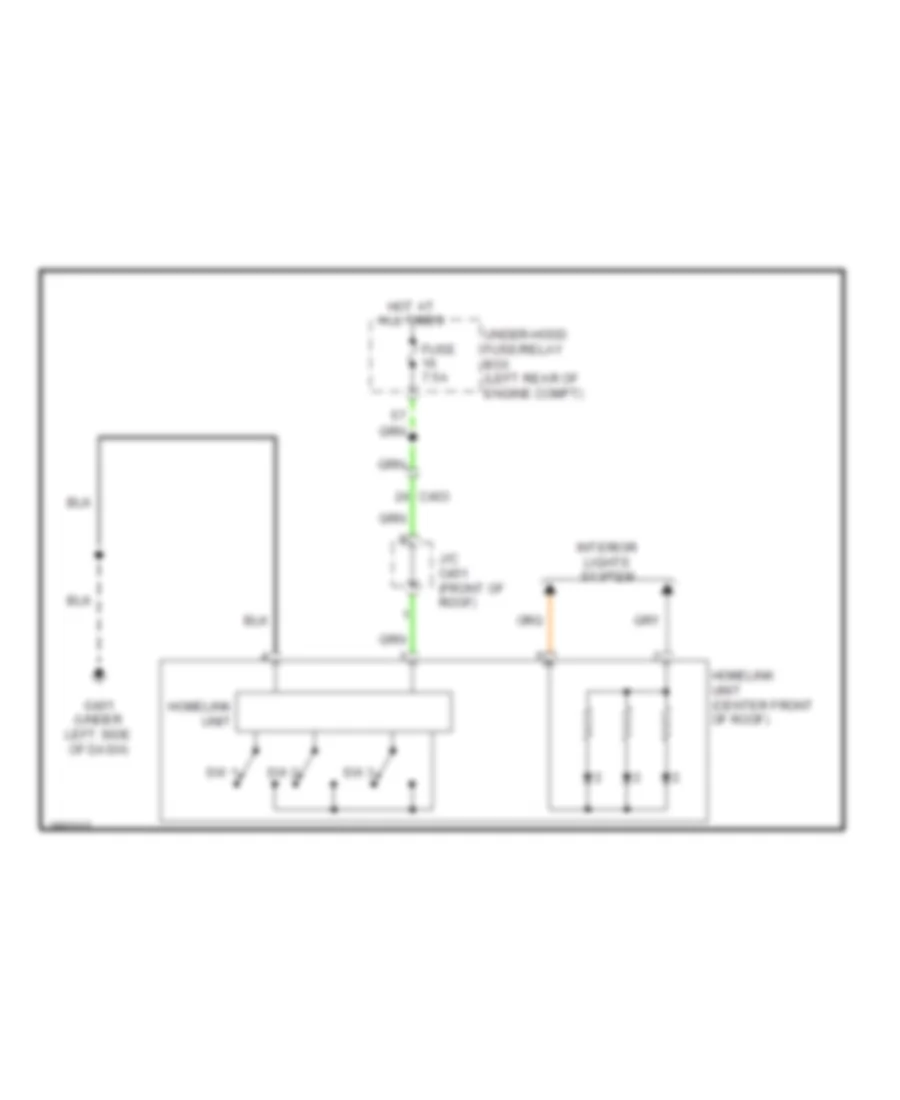 https://portal-diagnostov.com/license.html
Automotive Electricians Portal FZCO
Automotive Electricians Portal FZCO
https://portal-diagnostov.com/license.html
https://portal-diagnostov.com/license.html
Automotive Electricians Portal FZCO
Automotive Electricians Portal FZCOList of elements for Home Link Remote Control Wiring Diagram for Honda Crosstour EX 2012:
- C403
- Fuse 7.5a
- G401 (under left side of dash)
- Homelink unit
- Homelink unit (center front of roof)
- Hot at all times
- Interior lights system
- J/c c451 (front of roof)
- Sw 1
- Sw 2
- Sw 3
- Under-hood fuse/relay box (left rear of engine compt)
Navigation Wiring Diagram (1 of 2) for Honda Crosstour EX 2012
 https://portal-diagnostov.com/license.html
Automotive Electricians Portal FZCO
Automotive Electricians Portal FZCO
https://portal-diagnostov.com/license.html
https://portal-diagnostov.com/license.html
Automotive Electricians Portal FZCO
Automotive Electricians Portal FZCOList of elements for Navigation Wiring Diagram (1 of 2) for Honda Crosstour EX 2012:
- (behind middle of dash) g502
- (behind middle of dash) gps antenna
- (under left side of dash) center junction box
- (under right side of cargo area)
- 2.4l
- 3.5l
- A16
- A17
- A18
- A30
- Ac clk 1
- Ac si
- Ac so 1
- Acc
- Amplifier
- Audio unit
- B sig 1
- B10
- B11
- B12
- B13
- B14
- B15
- B16
- B17
- B18
- B19
- B20
- B21
- B22
- B23
- B24
- B25
- B26
- B27
- B28
- B29
- B30
- B31
- B32
- Back lt
- C sig 1
- C10
- C11
- C12
- C13
- C14
- C15
- C16
- C306
- C412
- C507
- C509
- C552
- C562
- Climate control unit
- Computer data lines system
- D24
- Diag +
- Diag -
- Driver's under-dash fuse/relay box (behind left kick panel)
- Ecu bus +
- Ecu bus -
- Exterior lights system
- Fcan h
- Fcan l
- Fuse 10a
- Fuse 7.5a
- G sig 1
- G701 (right side of floor)
- Gnd
- Gnd sig 1
- Gps sh
- Gps sig
- H17
- H26
- Hfl navi guide
- Hfl navi mic +
- Hfl navi mic-
- Hfl/navi comm 1
- Hfl/navi comm 2
- Hfl/navi comm 3
- Hfl/navi comm 4
- Hfl/navi comm sh
- Hot at all times
- Hot in acc or on
- Ill +
- Interface dial
- Interior lights system
- J/c c505 (behind middle of dash)
- J/c c506 (behind middle of dash)
- Jog
- Jog sh
- Navigation service check connector
- Navigation unit (under right side of cargo area)
- P16
- Passenger's under-dash fuse/relay box (behind right kick panel)
- Pcm (left front of engine compt)
- Pnk
- R sig 1
- Red
- Rg l +
- Rg l gnd
- Rg l sh
- Rgl gnd
- Rgl l+
- Rgl sh
- Sh ecu bus
- Sh sig 1
- Under- hood fuse/ relay box (left rear of engine compt)
- Vsp
Navigation Wiring Diagram (2 of 2) for Honda Crosstour EX 2012
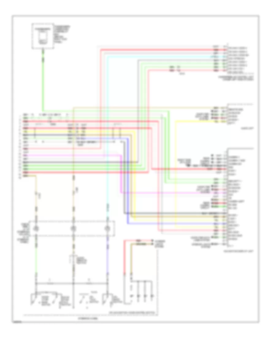 https://portal-diagnostov.com/license.html
Automotive Electricians Portal FZCO
Automotive Electricians Portal FZCO
https://portal-diagnostov.com/license.html
https://portal-diagnostov.com/license.html
Automotive Electricians Portal FZCO
Automotive Electricians Portal FZCOList of elements for Navigation Wiring Diagram (2 of 2) for Honda Crosstour EX 2012:
- (right side of floor) g701
- A11
- A12
- A18
- Acc
- Audio remote switch
- Audio unit
- B sig 1
- C sig 1
- C18
- C407
- C412
- C509
- Cable reel (a: in steering column) (c: in steering wheel)
- Camera adpt
- Camera sh
- Camera v
- Camera v gnd
- Computer data lines system
- D23
- E11
- E12
- Ecu bus +
- Ecu bus -
- G sig 1
- Ga bus +
- Ga bus -
- Ga bus sh
- Gnd
- Gnd sig 1
- Handsfreelink control unit (under left side of dash)
- Hfl back switch
- Hfl navi mic +
- Hfl navi mic -
- Hfl talk switch
- Hfl-navigation voice control switch
- Hfl/navi comm 1
- Hfl/navi comm 2
- Hfl/navi comm 3
- Hfl/navi comm 4
- Hfl/navi comm sh
- Ill +
- Interior lights system
- Navi strg sw
- Navig- ation back switch
- Navig- ation talk switch
- Navigation display unit
- Passenger's micu
- Passenger's under-dash fuse/relay box (behind right kick panel)
- R sig 1
- Rc gnd
- Rc vcc
- Rear camera circuit
- Red
- Remote gnd
- Scty radio
- Scty-
- Security +
- Sh ecu bus
- Sh sig 1
- Steering wheel
Rear Camera Wiring Diagram, with Rearview Display for Honda Crosstour EX 2012
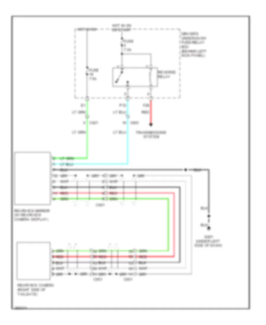 https://portal-diagnostov.com/license.html
Automotive Electricians Portal FZCO
Automotive Electricians Portal FZCO
https://portal-diagnostov.com/license.html
https://portal-diagnostov.com/license.html
Automotive Electricians Portal FZCO
Automotive Electricians Portal FZCOList of elements for Rear Camera Wiring Diagram, with Rearview Display for Honda Crosstour EX 2012:
- C403
- C421
- C601
- C651
- Driver's under-dash fuse/relay box (behind left kick panel)
- F28
- Fuse 7.5a
- G401 (under left side of dash)
- Hot in on
- Hot in on or start
- P12
- Rearview camera (right side of tailgate)
- Rearview mirror (w/ rearview camera display)
- Red
- Reverse relay
- Transmissions system
Rear Camera Wiring Diagram, without Rearview Display for Honda Crosstour EX 2012
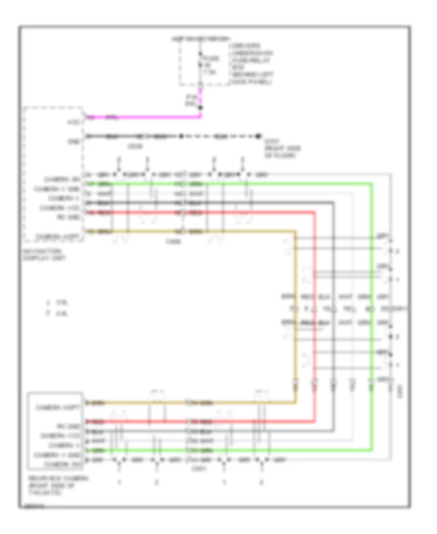 https://portal-diagnostov.com/license.html
Automotive Electricians Portal FZCO
Automotive Electricians Portal FZCO
https://portal-diagnostov.com/license.html
https://portal-diagnostov.com/license.html
Automotive Electricians Portal FZCO
Automotive Electricians Portal FZCOList of elements for Rear Camera Wiring Diagram, without Rearview Display for Honda Crosstour EX 2012:
- 2.4l
- 3.5l
- Acc
- C401
- C408
- C509
- C601
- C651
- Camera adpt
- Camera sh
- Camera v
- Camera v gnd
- Camera vcc
- Driver's under-dash fuse/relay box (behind left kick panel)
- Fuse 7.5a
- G701 (right side of floor)
- Gnd
- Hot in acc or on
- Navigation display unit
- Rc gnd
- Rearview camera (right side of tailgate)
- Red
POWER DISTRIBUTION
Power Distribution Wiring Diagram (1 of 7) for Honda Crosstour EX 2012
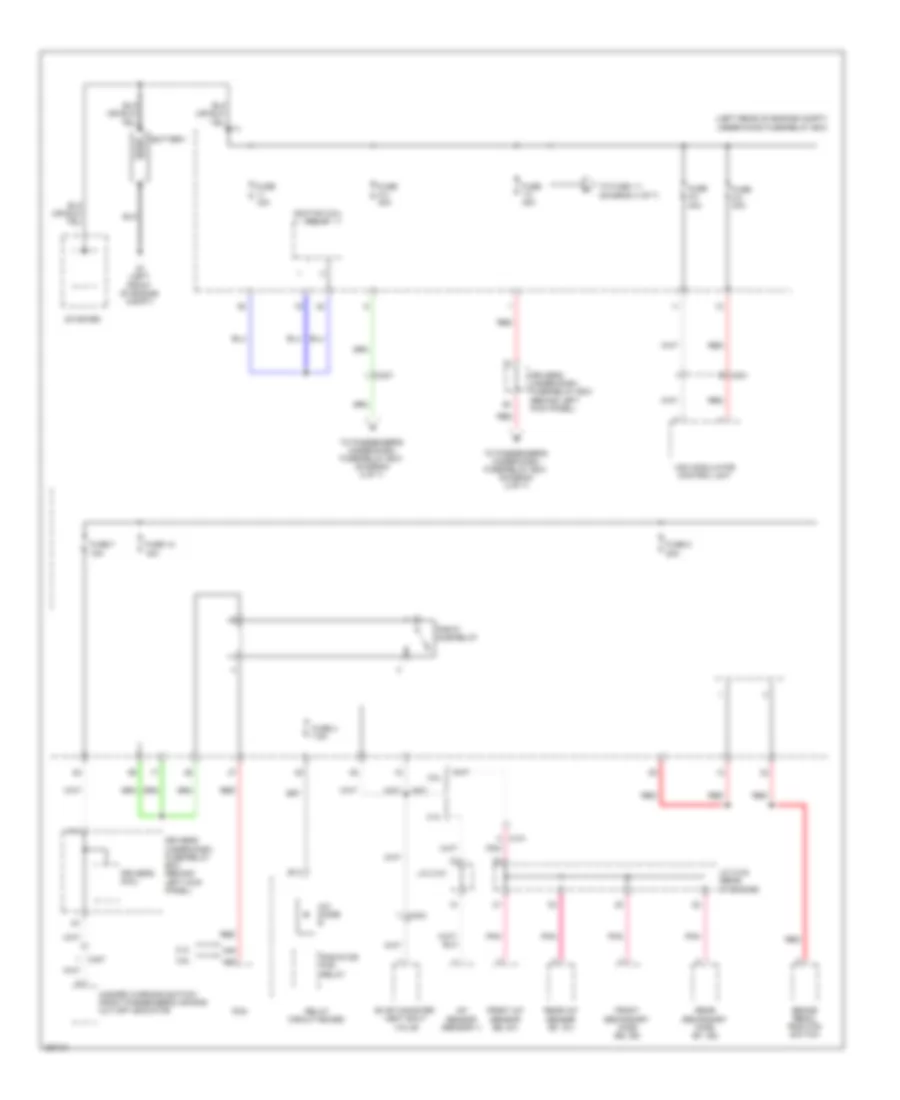 https://portal-diagnostov.com/license.html
Automotive Electricians Portal FZCO
Automotive Electricians Portal FZCO
https://portal-diagnostov.com/license.html
https://portal-diagnostov.com/license.html
Automotive Electricians Portal FZCO
Automotive Electricians Portal FZCOList of elements for Power Distribution Wiring Diagram (1 of 7) for Honda Crosstour EX 2012:
- (diagram 4 of 7)
- (left rear of engine compt) under-hood fuse/relay box
- 2.4l
- 3.5l
- A/c diode b
- A/f sensor (sensor 1)
- A40
- A49
- B13
- Battery
- Brake pedal position switch
- C101
- C201
- C304
- C307
- C407
- Driver's micu
- Driver's under-dash fuse/relay box (behind left kick panel)
- Evap canister vent shut valve
- F11
- Front a/f sensor (b2, s1)
- Front secondary ho2s (b2, s2)
- Fuse 1-2 40a
- Fuse 12 15a
- Fuse 15a
- Fuse 2-2 40a
- Fuse 2-3 30a
- Fuse 2-4 40a
- Fuse 4 7.5a
- Fuse 7 15a
- Fuse 8 20a
- G1 (left front of engine compt)
- Hazard warning switch/ front passenger's air bag cut-off indicator
- Ignition coil relay
- J/c c101
- J/c c104 (rear of engine)
- Pcm
- Pgm-fi sub-relay
- Pnk
- Radiator fan relay
- Rear a/f sensor (b1, s1)
- Rear secondary ho2s (b1, s2)
- Red
- Relay circuit board
- Starter
- To fuse 1-1
- To passenger's under-dash fuse/relay box (diagram 2 of 7)
- Vsa modulator control unit
Power Distribution Wiring Diagram (2 of 7) for Honda Crosstour EX 2012
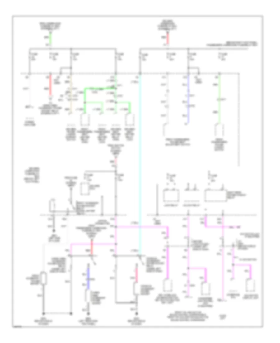 https://portal-diagnostov.com/license.html
Automotive Electricians Portal FZCO
Automotive Electricians Portal FZCO
https://portal-diagnostov.com/license.html
https://portal-diagnostov.com/license.html
Automotive Electricians Portal FZCO
Automotive Electricians Portal FZCOList of elements for Power Distribution Wiring Diagram (2 of 7) for Honda Crosstour EX 2012:
- (behind right kick panel) passenger's under-dash fuse/relay box
- (not used)
- (option connector)
- A10
- A11
- A12
- A17
- A24
- A7 (not used)
- Audio unit
- C402
- C403
- C411
- C701
- C702
- C811
- Cargo area accessory power socket
- Cargo area accessory power socket relay (under left side of dash)
- Center junction box (under left side of dash)
- Console accessory power socket
- Console accessory power socket relay (under left side of dash)
- D13
- D24
- Driver's micu
- Driver's power lumbar support switch
- Driver's seat heater relay (high)
- Driver's seat heater relay (low)
- Driver's under-dash fuse/relay box (behind left kick panel)
- Driver's under-dash fuse/relay box (diagram 1 of 7)
- Ex-l
- From fuse (diagram 4 of 7)
- From ignition switch (diagram 3 of 7)
- From passenger's under-dash fuse/relay box (diagram 2 of 7)
- From under-hood fuse/relay box (diagram 1 of 7)
- Front accessory power socket
- Front accessory power socket relay (cigar lighter relay)
- Front hfl-anc/active sound control microphone & front hfl-navigation-anc/active sound control microphone
- Front passenger's power seat adjustment switch
- Front passenger's power window switch
- Front passenger's seat heater relay (high)
- Front passenger's seat heater relay (low)
- Fuse 10a
- Fuse 15a
- Fuse 20a
- Fuse 7.5a
- G403 (behind middle of dash)
- G601 (left side of floor)
- G603 (left rear side trim panel)
- H17
- H8 (not used)
- Handsfree- link control unit (if equipped)
- Interface dial
- J/c c505 (behind middle of dash)
- Key interlock solenoid/ignition key switch/ignition key light
- Lock relay
- Navigation display unit
- Navigation unit (if equipped)
- P16
- P20
- Pnk
- Red
- Right rear power window relay
- Stereo amplifier
- To cargo area accessory power socket relay (diagram 2 of 7)
- Unlock relay
- W/ navigation
Power Distribution Wiring Diagram (3 of 7) for Honda Crosstour EX 2012
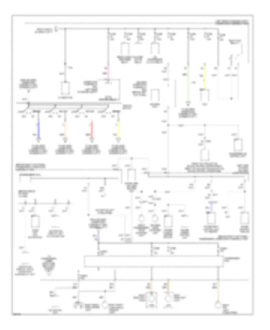 https://portal-diagnostov.com/license.html
Automotive Electricians Portal FZCO
Automotive Electricians Portal FZCO
https://portal-diagnostov.com/license.html
https://portal-diagnostov.com/license.html
Automotive Electricians Portal FZCO
Automotive Electricians Portal FZCOList of elements for Power Distribution Wiring Diagram (3 of 7) for Honda Crosstour EX 2012:
- (behind middle of dash) j/c c506
- (behind right kick panel) passenger's under-dash fuse/relay box
- (left rear of engine compt) under-hood fuse/relay box
- (left side of dash) driver's junction box
- 3.5l
- A/c compressor clutch relay
- A16
- A18
- A23
- Acc
- Alternator
- Audio unit (w/o navigation)
- Audio-hvac display unit & audio-hvac sub-display unit
- B12
- B25
- Blower motor relay
- C403
- C411
- C701
- C811
- Dlc
- Driver's door courtesy light
- Driver's micu
- Driver's under-dash fuse/relay box (behind left kick panel)
- E17
- E18
- Etcs control relay
- F16
- From driver's under-dash fuse/relay box (diagram 4 of 7)
- From fuse 3-8 (diagram 4 of 7)
- Front hfl-anc/active sound control microphone & front hfl-navigation-anc/active sound control microphone
- Front passenger's door courtesy light
- Fuse 10a
- Fuse 15a
- Fuse 2 10a
- Fuse 3 10a
- Fuse 40a
- Fuse 6 7.5a
- Fuse 7.5a
- G10
- Gauge control module
- H14
- H26
- Handsfreelink control unit
- High
- Ignition switch
- Immobilizer keyless control unit
- Lock
- Low
- Navigation display unit (w/ navigation)
- Navigation unit
- Navigation unit (if equipped)
- Passenger's micu
- Pcm
- Pgm-fi main relay 1
- Power mirror control unit
- Power seat control unit (w/ memory)
- Power window master switch
- Rear window defogger relay
- Red
- Right fog light (if equipped)
- Right front side marker light
- Right front turn signal/ parking light
- Right headlight (high)
- Right headlight (low)
- Start
- T102
- To driver's under-dash fuse/relay box (diagram 2 of 7)
- To driver's under-dash fuse/relay box (diagram 5 of 7)
- To driver's under-dash fuse/relay box (diagram 6 of 7)
- To driver's under-dash fuse/relay box (diagram 7 of 7)
- To passenger's under- dash fuse/ relay box diagram 5 of 7)
- Under-hood fuse/relay box (left rear of engine compt)
Power Distribution Wiring Diagram (4 of 7) for Honda Crosstour EX 2012
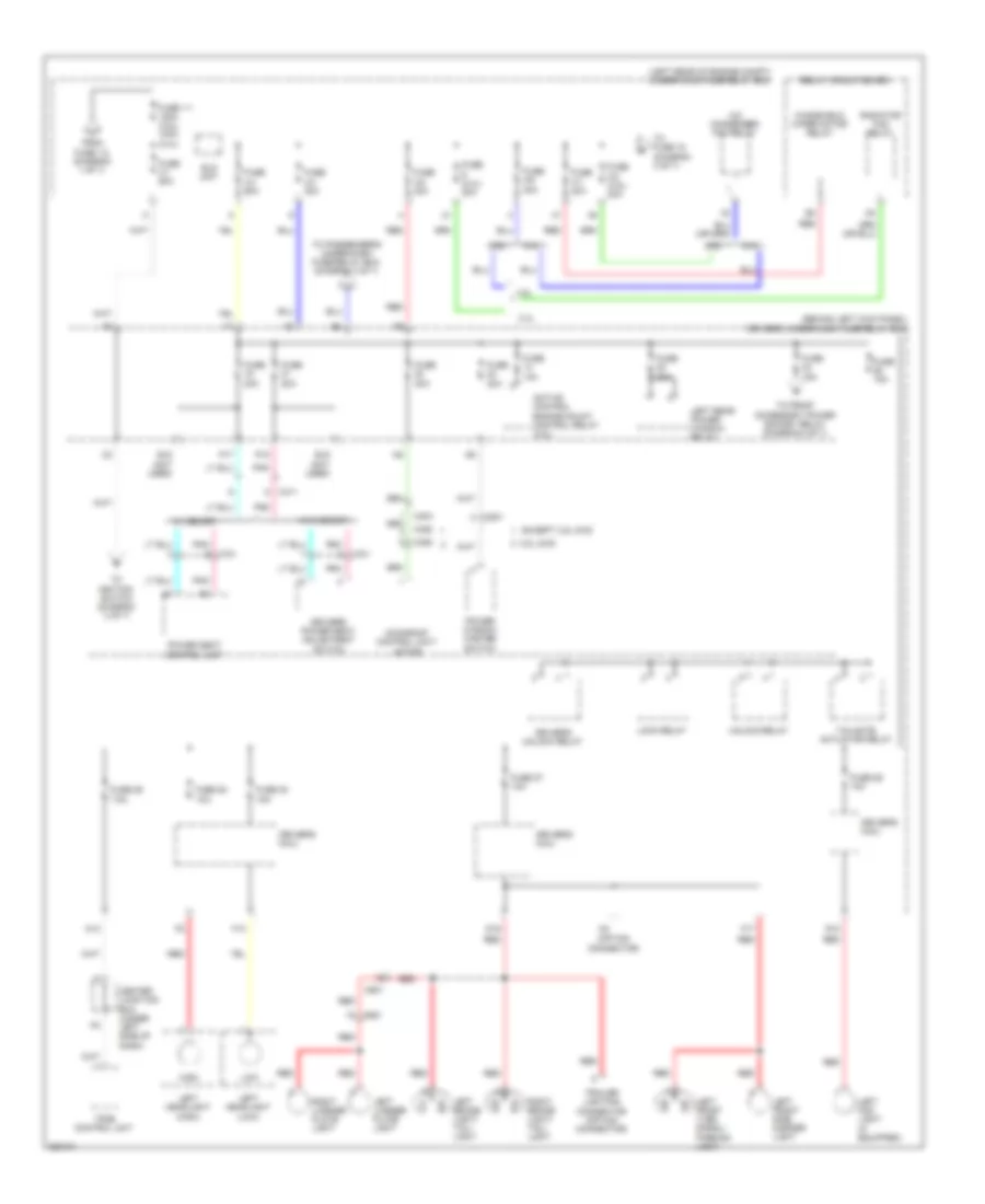 https://portal-diagnostov.com/license.html
Automotive Electricians Portal FZCO
Automotive Electricians Portal FZCO
https://portal-diagnostov.com/license.html
https://portal-diagnostov.com/license.html
Automotive Electricians Portal FZCO
Automotive Electricians Portal FZCOList of elements for Power Distribution Wiring Diagram (4 of 7) for Honda Crosstour EX 2012:
- (behind left kick panel) driver's under-dash fuse/relay box
- (left rear of engine compt) under-hood fuse/relay box
- (option connector)
- 2.4l
- 3.5l
- 3.5l 2wd
- A/c condenser fan relay
- Active control engine mount control relay (3.5l)
- C404
- C411
- C452
- C601
- C651
- C801
- Center junction box (under left side of dash)
- D16
- Driver's micu
- Driver's power seat adjustment switch
- Driver's unlock relay
- E18 (not used)
- E19 (not used)
- Eld unit
- Except 3.5l 2wd
- F13
- F17
- From fuse 1-2 (diagram 1 of 7)
- Fuse (2.4l) 20a
- Fuse 1-1 120a (3.5l) 100a (2.4l)
- Fuse 10a
- Fuse 15a
- Fuse 20a
- Fuse 26 10a
- Fuse 27 10a
- Fuse 28 10a
- Fuse 29 7.5a
- Fuse 3-1 50a
- Fuse 3-3 30a
- Fuse 3-4 60a
- Fuse 3-5 30a
- Fuse 3-6 30a
- Fuse 3-7 30a
- Fuse 3-8 (3.5l) 30a
- Fuse 30 15a
- G10
- High
- Left brake light/ tail- light
- Left fog light (if equipped)
- Left front side marker light
- Left front turn signal/ parking light
- Left headlight (high)
- Left headlight (low)
- Left license plate light
- Left rear power window relay
- Lock relay
- Low
- Moonroof control unit/ motor
- N13
- P17
- P18
- Pnk
- Pnk c701
- Power seat control unit
- Power window master switch
- Radiator fan relay
- Red
- Relay circuit board
- Right brake light/ tail- light
- Right license plate light
- Tailgate actuator relay
- To front accessory power socket relay (diagram 2 of 7)
- To fuse 18 (diagram 3 of 7)
- To ignition switch (diagram 3 of 7)
- To passenger's under-dash fuse/relay box (diagram 3 of 7)
- Tpms control unit
- Trailer lighting connector (option connector)
- Unlock relay
- W/ memory
- W/o memory
- Windshield wiper motor relay
Power Distribution Wiring Diagram (5 of 7) for Honda Crosstour EX 2012
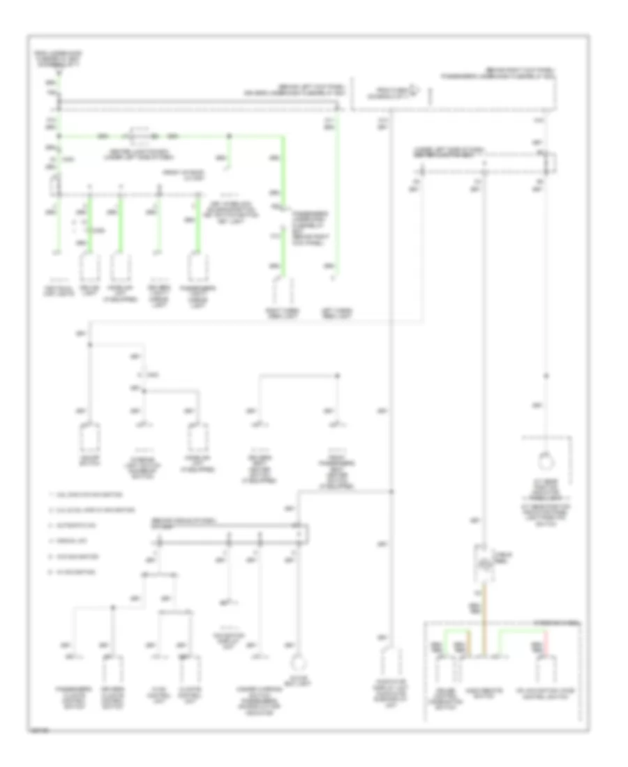 https://portal-diagnostov.com/license.html
Automotive Electricians Portal FZCO
Automotive Electricians Portal FZCO
https://portal-diagnostov.com/license.html
https://portal-diagnostov.com/license.html
Automotive Electricians Portal FZCO
Automotive Electricians Portal FZCOList of elements for Power Distribution Wiring Diagram (5 of 7) for Honda Crosstour EX 2012:
- (behind left kick panel) driver's under-dash fuse/relay box
- (behind middle of dash) j/c c505
- (behind right kick panel) passenger's under-dash fuse/relay box
- (front of roof) j/c c451
- (under left side of dash) center junction box
- 2.4l & 3.5l 4wd w/ navigation
- 3.5l 2wd w/o navigation
- A/t gear position indicator panel light
- A/t gear position indicator panel light/park pin switch
- A19
- A22
- A25
- Audio remote switch
- Audio-hvac display unit audio-hvac sub-display unit
- Automatic a/c
- C403
- C452
- Cable reel
- Ceiling light
- Center junction box (under left side of dash)
- Climate control unit
- Cruise control combination switch
- D11
- D14
- Driver's climate control switch
- Driver's seat heater switch (if equipped)
- Driver's vanity mirror light
- F26
- From fuse 6 m (diagram 3 of 7)
- From under-hood fuse/relay box (diagram 3 of 7)
- Front passenger's seat heater switch (if equipped)
- Glove box light
- H13
- Hazard warning switch/ passenger's air bag cut-off indicator
- Hfl-navigation voice control switch
- Homelink unit (if equipped)
- Hvac control unit
- Individual map lights
- Interior light switch (moonroof switch)
- Key interlock solenoid/ignition key switch/ignition key light
- Left cargo area light
- Manual a/c
- Navigation display unit
- P10
- Passenger's climate control switch
- Passenger's under-dash fuse/relay box (behind right kick panel)
- Passenger's vanity mirror light
- Right cargo area light
- Steering wheel
- Vsa off switch
- W/ navigation
- W/o navigation
Power Distribution Wiring Diagram (6 of 7) for Honda Crosstour EX 2012
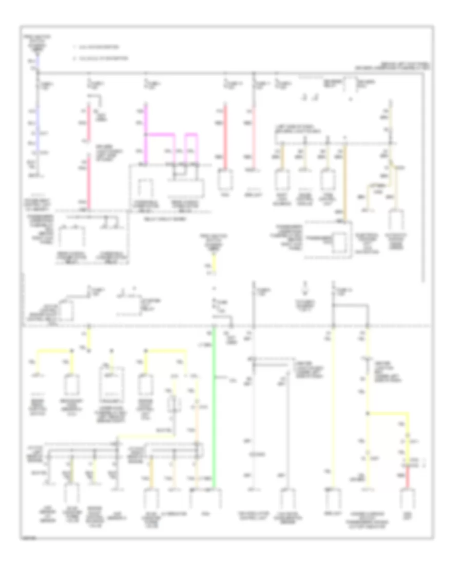 https://portal-diagnostov.com/license.html
Automotive Electricians Portal FZCO
Automotive Electricians Portal FZCO
https://portal-diagnostov.com/license.html
https://portal-diagnostov.com/license.html
Automotive Electricians Portal FZCO
Automotive Electricians Portal FZCOList of elements for Power Distribution Wiring Diagram (6 of 7) for Honda Crosstour EX 2012:
- (behind left kick panel) driver's under-dash fuse/relay box
- (left side of dash) driver's junction box
- (not used)
- 2.4l
- 2.4l w/o navigation
- 3.4l & 2.4l w/ navigation
- 3.5l
- A22
- A23
- A28
- A31
- A32
- Active control engine mount control relay (3.5l)
- Alternator
- Automatic dimming inside mirror
- B27
- Brake pedal position switch
- C101
- C202
- C403
- C407
- C411
- C452
- C701
- C702
- Center junction box (under left side of dash)
- Cmp sensor a
- D10
- Driver's junction box (left side of dash)
- Driver's micu
- Eld unit
- Electrical compass unit (w/o navigation)
- Engine mount control solenoid valve
- Engine mount control unit (3.5l)
- Evap canister purge valve
- F15
- F25
- From ignition switch (diagram 3 of 7)
- Fuse 10 10a
- Fuse 11 10a
- Fuse 12 7.5a
- Fuse 2 7.5a
- Fuse 3 15a
- Fuse 4 10a
- Fuse 5 7.5a
- Fuse 6 7.5a
- Fuse 7 15a
- Fuse 7.5a
- Gauge control module
- Hazard warning switch/ passenger's air bag cut-off indicator
- J/c c103 (left rear of engine)
- J/c c105 (right rear of engine)
- Maf sensor/ iat sensor
- N12
- Ods unit
- Passenger's micu
- Passenger's under-dash fuse/relay box (behind right kick panel)
- Pcm
- Pnk
- Power seat control unit (w/ memory)
- Rear window washer motor relay
- Rear window wiper motor relay
- Red
- Relay circuit board
- Reverse relay
- Secondary ho2s (sensor 2) (2.4l)
- Shift lock solenoid
- Srs unit
- Starter cut relay
- Tan
- To fuse 9 (diagram 7 of 7)
- Tpms control unit
- Under-hood fuse/relay box (left rear of engine compt)
- Vsa modulator control unit
- Windshield washer motor relay
- Windshield wiper motor relay
- Yaw rate- acceleration sensor
Power Distribution Wiring Diagram (7 of 7) for Honda Crosstour EX 2012
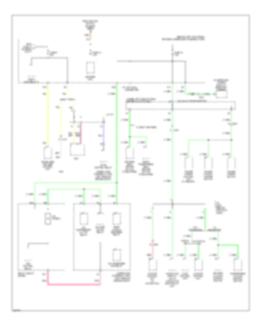 https://portal-diagnostov.com/license.html
Automotive Electricians Portal FZCO
Automotive Electricians Portal FZCO
https://portal-diagnostov.com/license.html
https://portal-diagnostov.com/license.html
Automotive Electricians Portal FZCO
Automotive Electricians Portal FZCOList of elements for Power Distribution Wiring Diagram (7 of 7) for Honda Crosstour EX 2012:
- (behind left kick panel) driver's under-dash fuse/relay box
- (optional connector)
- (under left side of dash) center junction box
- (w/ rearview camera display) rearview mirror
- 2.4l
- 3.5l
- 3.5l & 2.4l w/o navigation
- A/c compressor clutch relay
- A/c condenser fan relay
- A/c diode a
- Audio-hvac display unit & audio-hvac sub display unit
- Automatic a/c
- B11
- B12
- B42
- Blower motor relay
- C10
- C101
- C407
- C421
- C507
- C801
- Climate control unit
- Climate control unit (w/ navigation)
- Driver's climate control switch
- Driver's micu
- Driver's seat heater switch (if equipped)
- Etcs control relay
- F29
- Fan control relay
- From fuse 12 p (diagram 6 of 7)
- From ignition switch (diagram 3 of 7)
- Front passenger's seat heater switch (if equipped)
- Fuse 15 7.5a
- Fuse 16 7.5a
- Fuse 9 20a
- Hvac control unit
- Immobilizer keyless control unit
- J/c 101
- J/c c506 (behind middle of dash)
- Manual a/c
- P11
- P19
- Passenger's climate control switch
- Pcm
- Pgm-fi main relay 2
- Pnk
- Power mirror control unit (w/ memory)
- Power mirror switch
- Power window master switch
- Rear window defogger relay
- Red
- Relay circuit board
- Under- hood fuse/relay box (left rear of engine compt)
- Under-hood fuse/relay box (left rear of engine compt)
- W/ navigation
- W/ seat heaters
- W/o navigation
POWER DOOR LOCKS
Power Door Locks Wiring Diagram (1 of 3) for Honda Crosstour EX 2012
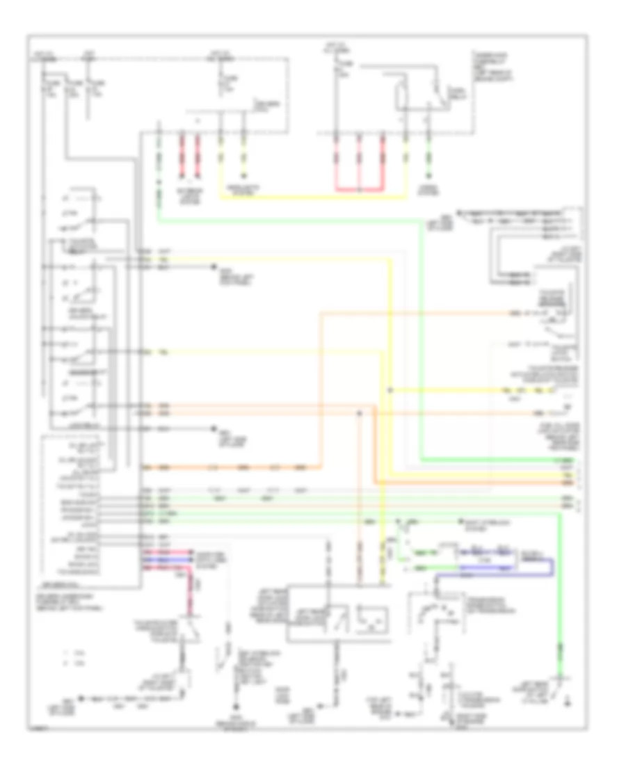 https://portal-diagnostov.com/license.html
Automotive Electricians Portal FZCO
Automotive Electricians Portal FZCO
https://portal-diagnostov.com/license.html
https://portal-diagnostov.com/license.html
Automotive Electricians Portal FZCO
Automotive Electricians Portal FZCOList of elements for Power Door Locks Wiring Diagram (1 of 3) for Honda Crosstour EX 2012:
- (right side of engine) g101
- (top left rear of engine) g101
- 2.4l
- 3.5l
- Atp-p
- B-can hi
- B-can low
- C101
- C106
- C401
- C601
- C651
- C821
- Computer data lines system
- D/l dr fr unlck rly cl-
- D/l dr lck rly cl-
- D/l dr unlock rly cl-
- D/l sil-con sw rr-l (unlock)
- D10
- D12
- D15
- D16
- Door lock knob
- Driver's micu
- Driver's under-dash fuse/relay box (behind left kick panel)
- Driver's unlock relay
- Eng hood sw
- Exterior lights system
- F13
- F17
- F23
- F32
- Fr door sw l
- Fuel fill door lock actuator (behind left rear side trim panel)
- Fuse 10a
- Fuse 15a
- Fuse 20a
- Fuse 7.5a
- G302 (behind left kick panel)
- G403 (behind middle of dash)
- G601 (left side of floor)
- Headlights system
- Horn relay
- Horns system
- Hot at all times
- Hot in on
- J/c c101
- J/c c106 (transmission housing)
- J/c c671 (right side of tailgate)
- Key interlock solenoid/ ignition key switch/ ignition key light
- Key sw
- Left rear door lock actuator/ knob switch (rear of left rear door)
- Left rear door lock knob switch
- Left rear door switch (at left "c" pillar)
- Lock relay
- Lr door sw l
- P11
- Pnk
- Q13
- Red
- Shift interlock system
- T/g act rly cl-
- T/g handle sw
- T/g sw
- Tailgate actuator relay
- Tailgate latch switch
- Tailgate outer handle switch (middle of tailgate)
- Tailgate release actuator
- Tailgate release actuator/latch switch (middle of tailgate)
- Transmission range switch (on transmission)
- Under-hood fuse/relay box (left rear of engine compt)
- Unlock relay
Power Door Locks Wiring Diagram (2 of 3) for Honda Crosstour EX 2012
 https://portal-diagnostov.com/license.html
Automotive Electricians Portal FZCO
Automotive Electricians Portal FZCO
https://portal-diagnostov.com/license.html
https://portal-diagnostov.com/license.html
Automotive Electricians Portal FZCO
Automotive Electricians Portal FZCOList of elements for Power Door Locks Wiring Diagram (2 of 3) for Honda Crosstour EX 2012:
- A12
- A21
- A34
- Audio unit
- B-can hi
- B-can lo
- C831
- Computer data lines system
- D/l as lck rly cl-
- D/l as unlck rly cl-
- D/l sil-con rr-r (unlock)
- D23
- Door lock knob
- Driver's door switch (at driver's "b" pillar)
- E18
- Exterior lights system
- Fr door sw r
- Front passenger's door switch (at front passenger's "b" pillar)
- Fuse 10a
- Fuse 20a
- G302 (behind left kick panel)
- G701 (right side of floor)
- H10
- H24
- H35
- H38
- Headlights system
- Hot at all times
- Lock relay
- Navigation display unit
- Passenger's micu
- Passenger's under-dash fuse/relay box (behind right kick panel)
- Pnk
- Red
- Right rear door lock actuator/ knob switch (rear of right rear door)
- Right rear door lock knob switch
- Right rear door switch (at right "c" pillar)
- Rr door sw r
- Scty radio
- Security +
- Security -
- Security hood switch (behind middle of front bumper)
- Unlock relay
- W/ navigation
- W/o navigation
Power Door Locks Wiring Diagram (3 of 3) for Honda Crosstour EX 2012
 https://portal-diagnostov.com/license.html
Automotive Electricians Portal FZCO
Automotive Electricians Portal FZCO
https://portal-diagnostov.com/license.html
https://portal-diagnostov.com/license.html
Automotive Electricians Portal FZCO
Automotive Electricians Portal FZCOList of elements for Power Door Locks Wiring Diagram (3 of 3) for Honda Crosstour EX 2012:
- (behind glove box) g405
- (left side of dash) driver's junction box
- 0) neutral 1) lock 2) unlock door lock switch
- 2.4l
- 3.5l
- 5v stabilizer circuit/ controller area network controller
- A28
- B can hi
- B can lo
- B-canh
- B-canl
- Blinking circuit
- Body controller area network
- C801
- C811
- Center junction box (under left side of dash)
- Computer data lines system
- Control unit
- Dlc (under left side of dash)
- Door lock knob
- Door lock switch 0) neutral 1) lock 2) unlock
- Door lock switch lock light
- Door lock switch unlock light
- Driver's door key cylinder switch
- Driver's door lock actuator/knob switch/ key cylinder switch (on driver's door)
- Driver's door lock knob switch
- Driver's junction box (left side of dash)
- Driver's micu
- Driver's under-dash fuse/relay box (behind left kick panel)
- E14
- E15
- Front passenger's door lock actuator/ knob switch (in front passenger's door)
- Front passenger's door lock knob switch
- Front passenger's power window switch
- Fuse 10a
- Fuse 7.5a
- G203 (behind glove box)
- G401 (under left side of dash)
- G402 (under left side of dash)
- Gauge control module
- Hot at all times
- Hot in on or start
- Ig1
- Ig1 meter
- Ig2
- Immobilizer keyless control unit (in steering column)
- Kc dr lock
- Kc dr ul
- Key
- Lock
- Meter
- P-gnd
- Passenger's micu
- Passenger's under-dash fuse/relay box (behind right kick panel)
- Pnk
- Power distribution system
- Power window master switch (door multiplex control unit)
- Q10 micu-p
- R8 micu-p
- Red
- S-gnd
- Security ind
- Sil as ul
- Sil dr lock
- Sil dr ul
- Transceiver
- Uart
- Under- hood fuse/ relay box (left rear of engine compt)
- Unlock
- Vbu
- Vmp as uart
- Vmp dr
POWER MIRRORS
Automatic Day/Night Mirror Wiring Diagram for Honda Crosstour EX 2012
 https://portal-diagnostov.com/license.html
Automotive Electricians Portal FZCO
Automotive Electricians Portal FZCO
https://portal-diagnostov.com/license.html
https://portal-diagnostov.com/license.html
Automotive Electricians Portal FZCO
Automotive Electricians Portal FZCOList of elements for Automatic Day/Night Mirror Wiring Diagram for Honda Crosstour EX 2012:
- (or red)
- 2.4l
- 3.5l
- A/t reverse relay
- A48
- A49
- Atpr
- Automatic dimming inside mirror
- B15
- Back lt
- C101
- C106
- C25
- C403
- C412
- Computer data lines system
- Driver's junction box (left side of dash)
- Driver's micu
- Driver's under-dash fuse/relay box (behind left kick panel)
- Exterior lights system
- F-canh
- F-canl
- F28
- Fuse 5 7.5a
- G101 (3.5l: right side of engine) (2.4l: top left rear of engine)
- G401 (under left side of dash)
- Gnd
- Hot in on or start
- Ig1
- J/c c106 (transmission housing)
- J/c c107 (3.5l) j/c c101 (2.4l) (c107: top of transmission)
- Navigation unit (if equipped) (under right side of cargo area)
- P12
- Pcm (left front of engine compt)
- Red
- Transmission range switch (on transmission)
Power Mirrors Wiring Diagram for Honda Crosstour EX 2012
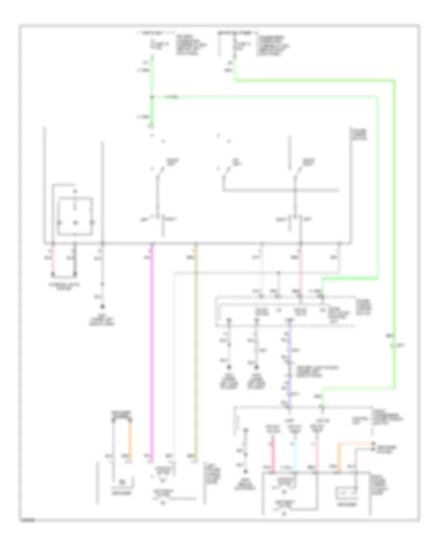 https://portal-diagnostov.com/license.html
Automotive Electricians Portal FZCO
Automotive Electricians Portal FZCO
https://portal-diagnostov.com/license.html
https://portal-diagnostov.com/license.html
Automotive Electricians Portal FZCO
Automotive Electricians Portal FZCOList of elements for Power Mirrors Wiring Diagram for Honda Crosstour EX 2012:
- C801
- C811
- Center junction box (under left side of dash)
- Control unit
- Defogger
- Defogger system
- Door multiplex control unit
- Down/ left
- Down/ right
- Driver's under-dash fuse/relay box (behind left kick panel)
- Front passenger's power window switch
- Fuse 13 20a
- Fuse 16 7.5a
- G401 (under left side of dash)
- G402 (under left side of dash)
- G405 (behind glove box)
- Hot at all times
- Hot in on
- Ig2
- Interior lights system
- Left
- Left power mirror (in left door)
- Left/right motor
- Mir act as com
- Mir act as lr
- Mir act as ud
- Mir sw as com
- Mir sw as lr
- P11
- Passenger's under-dash fuse/relay box (behind right kick panel)
- Pnk
- Power mirror switch
- Power window master switch
- Red
- Right
- Right power mirror (in right door)
- Uart
- Up/ left
- Up/down motor
- Vmp as
POWER SEATS
Driver Power Seat Wiring Diagram for Honda Crosstour EX 2012
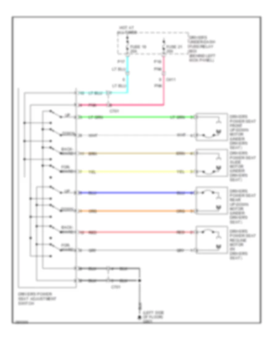 https://portal-diagnostov.com/license.html
Automotive Electricians Portal FZCO
Automotive Electricians Portal FZCO
https://portal-diagnostov.com/license.html
https://portal-diagnostov.com/license.html
Automotive Electricians Portal FZCO
Automotive Electricians Portal FZCOList of elements for Driver Power Seat Wiring Diagram for Honda Crosstour EX 2012:
- (left side of floor) g801
- Back- ward
- C411
- C701
- Down
- Driver's power seat adjustment switch
- Driver's power seat front up-down motor (under driver's seat)
- Driver's power seat rear up-down motor (under driver's seat)
- Driver's power seat recline motor (in driver's seat)
- Driver's power seat slide motor (under driver's seat)
- Driver's under-dash fuse/relay box (behind left kick panel)
- For- ward
- Fuse 19 20a
- Fuse 21 20a
- Hot at all times
- P17
- P18
- Pnk
- Red
Driver"s Lumbar Wiring Diagram for Honda Crosstour EX 2012
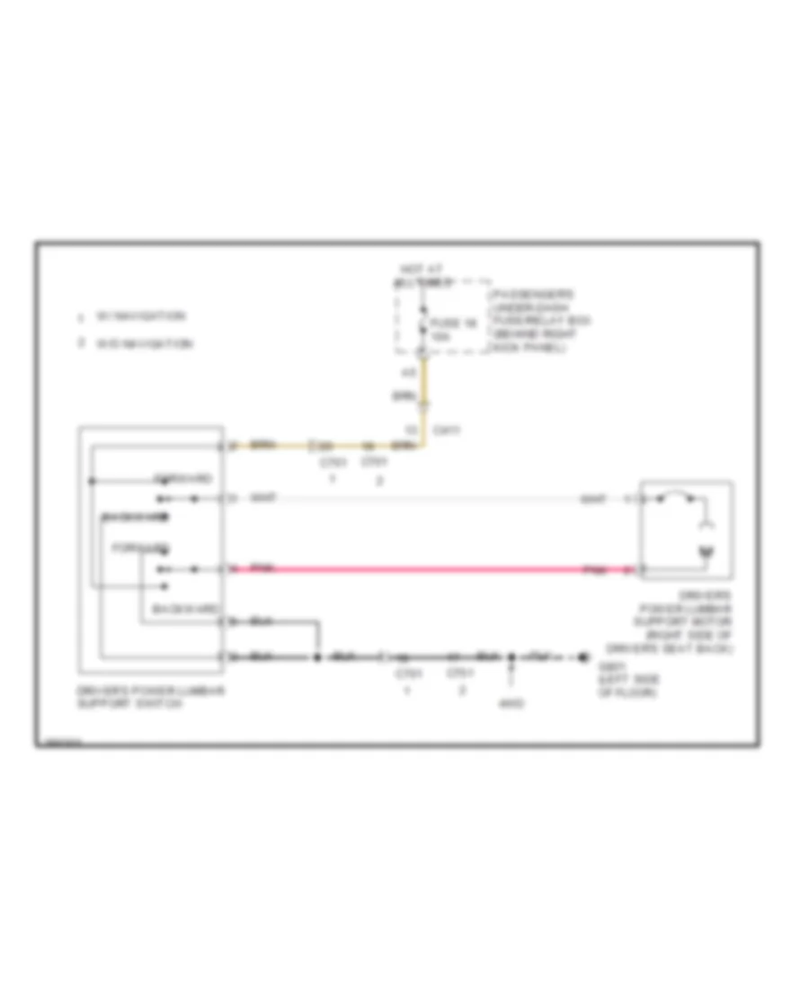 https://portal-diagnostov.com/license.html
Automotive Electricians Portal FZCO
Automotive Electricians Portal FZCO
https://portal-diagnostov.com/license.html
https://portal-diagnostov.com/license.html
Automotive Electricians Portal FZCO
Automotive Electricians Portal FZCOList of elements for Driver"s Lumbar Wiring Diagram for Honda Crosstour EX 2012:
- 4wd
- Backward
- C411
- C701
- Driver's power lumbar support motor (right side of driver's seat back)
- Driver's power lumbar support switch
- Forward
- Fuse 18 10a
- G801 (left side of floor)
- Hot at all times
- Passenger's under-dash fuse/relay box (behind right kick panel)
- Pnk
- W/ navigation
- W/o navigation
Heated Seats Wiring Diagram for Honda Crosstour EX 2012
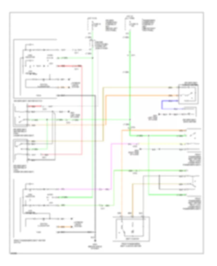 https://portal-diagnostov.com/license.html
Automotive Electricians Portal FZCO
Automotive Electricians Portal FZCO
https://portal-diagnostov.com/license.html
https://portal-diagnostov.com/license.html
Automotive Electricians Portal FZCO
Automotive Electricians Portal FZCOList of elements for Heated Seats Wiring Diagram for Honda Crosstour EX 2012:
- A10
- C411
- C701
- C702
- Center junction box (under left side of dash)
- Driver's seat back heater
- Driver's seat cushion heater
- Driver's seat heater relay (high) (under driver's seat)
- Driver's seat heater relay (low) (under driver's seat)
- Driver's seat heater switch
- Driver's under-dash fuse/relay box (behind left kick panel)
- Front passenger's seat cushion heater
- Front passenger's seat heater relay (high) (under front passenger's seat)
- Front passenger's seat heater relay (low) (under front passenger's seat)
- Front passenger's seat heater switch
- Fuse 16 7.5a
- Fuse 19 15a
- G403 (behind middle of dash)
- G801 (left side of floor)
- G802 (right side of floor)
- High
- High indicator
- Hot at all times
- Hot in on
- Interior lights system
- Low
- Low indicator
- P11
- Passenger's under-dash fuse/relay box (behind right kick panel)
- Red
- Seat cushion
- Switch illumination
Passenger Power Seat Wiring Diagram for Honda Crosstour EX 2012
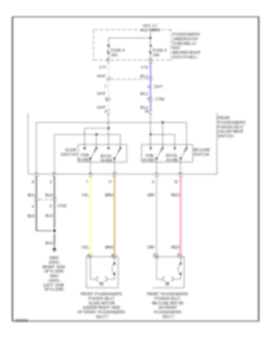 https://portal-diagnostov.com/license.html
Automotive Electricians Portal FZCO
Automotive Electricians Portal FZCO
https://portal-diagnostov.com/license.html
https://portal-diagnostov.com/license.html
Automotive Electricians Portal FZCO
Automotive Electricians Portal FZCOList of elements for Passenger Power Seat Wiring Diagram for Honda Crosstour EX 2012:
- A11
- A12
- Back- ward
- C411
- C702
- For- ward
- Front passenger's power seat adjustment switch
- Front passenger's power seat recline motor (in front passenger's seat)
- Front passenger's power seat slide motor (under right side of front passenger's seat)
- Fuse 8 20a
- Fuse 9 20a
- G802 (2wd) (right side of floor) g801 (4wd) (left side of floor)
- Hot at all times
- Passenger's under-dash fuse/relay box (behind right kick panel)
- Recline switch
- Red
- Slide switch
POWER TOP/SUNROOF
Power Top/Sunroof Wiring Diagram for Honda Crosstour EX 2012
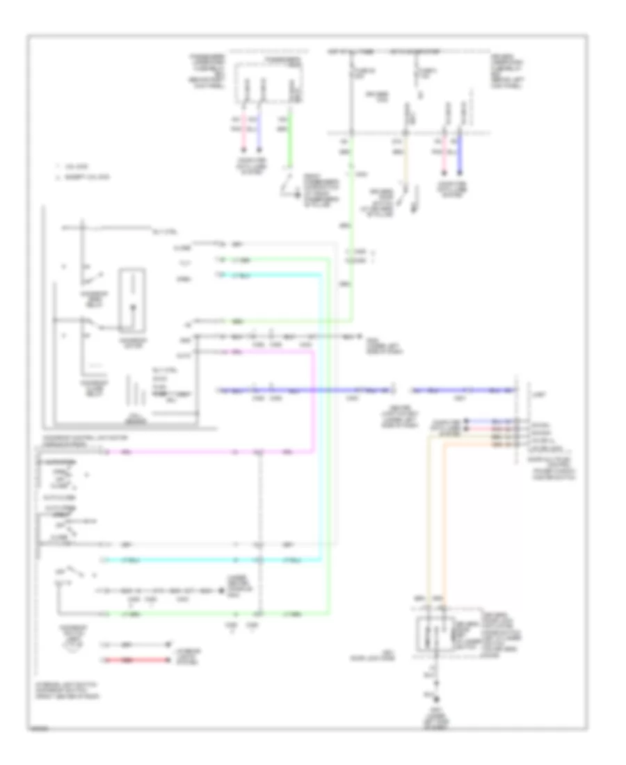 https://portal-diagnostov.com/license.html
Automotive Electricians Portal FZCO
Automotive Electricians Portal FZCO
https://portal-diagnostov.com/license.html
https://portal-diagnostov.com/license.html
Automotive Electricians Portal FZCO
Automotive Electricians Portal FZCOList of elements for Power Top/Sunroof Wiring Diagram for Honda Crosstour EX 2012:
- (under center console) g404
- 3.5l 2wd
- A21
- A34
- Auto
- Auto close
- Auto open
- B-can hi
- B-can lo
- B-canh
- B-canl
- C403
- C404
- C452
- C801
- Center junction box (under left side of dash)
- Close
- Computer data lines system
- Cpu
- D15
- Door multiplex control
- Driver's door key cylinder lock switch
- Driver's door lock actuator/ knob switch/ key cylinder switch (on driver's door)
- Driver's door switch (at driver's "b" pillar)
- Driver's micu
- Driver's under-dash fuse/relay box (behind left kick panel)
- Except 3.5l 2wd
- Fr door sw l
- Fr door sw r
- Front passenger's door switch (at front passenger's "b" pillar)
- Fuse 20 20a
- Fuse 5 7.5a
- G401 (under left side of dash)
- G402 (under left side of dash)
- Gnd
- H24
- Hall sensor
- Hot at all times
- Hot in on or start
- Ig1
- Interior light-switch (moonroof switch) (front center of roof)
- Interior lights system
- Kc dr lock
- Kc dr ul
- Key/ door lock knob
- Moonroof close relay
- Moonroof control unit/motor (middle of roof)
- Moonroof motor
- Moonroof open relay
- Moonroof switch light
- Off
- Open
- Passenger's micu
- Passenger's under-dash fuse/relay box (behind right kick panel)
- Plsa
- Plsb
- Pnk
- Power window master switch
- Red
- Rly ctrl
- Svcc
- Tilt
- Uart
- Unlock
POWER WINDOWS
Power Windows Wiring Diagram (1 of 3) for Honda Crosstour EX 2012
 https://portal-diagnostov.com/license.html
Automotive Electricians Portal FZCO
Automotive Electricians Portal FZCO
https://portal-diagnostov.com/license.html
https://portal-diagnostov.com/license.html
Automotive Electricians Portal FZCO
Automotive Electricians Portal FZCOList of elements for Power Windows Wiring Diagram (1 of 3) for Honda Crosstour EX 2012:
- (door multi-plex control unit)
- B-can hi
- B-can lo
- B-canh
- B-canl
- C801
- C821
- Computer data lines system
- Door lock knob
- Dr down
- Dr up
- Driver control block
- Driver's door key cylinder switch
- Driver's door lock actuator/knob switch/key cylinder switch (on driver's 1) unlock door) 2) lock
- Driver's micu
- Driver's power window motor (middle of driver's door)
- Driver's switch
- Driver's switch light
- Driver's under-dash fuse/relay box (behind left kick panel)
- Front passenger's switch light
- Fuse 16 7.5a
- Fuse 22 20a
- Fuse 24 20a
- Fuse 5 7.5a
- G401 (under left side of dash)
- G402 (under left side of dash)
- Gnd (micu-p)
- Gnd (micu-s)
- Hot at all times
- Hot in on
- Hot in on or start
- Ig1 meter
- Ig2
- Kc dr lock
- Kc dr ul
- Key
- Left rear power window relay
- Left rear switch
- Left rear switch light
- Main switch
- Main switch light
- P/w cont ill+
- P/w rr l rly cl-
- P11
- Passenger's switch
- Plsa dr
- Plsb dr
- Pnk
- Power window master switch
- Power window master switch illumination
- Pulser
- Q10
- R11
- Right rear switch
- Right rear switch light
- Rr rly dn
- Rr rly up
- Svcc dr
- Uart
- Vbu
- Vmp dr
Power Windows Wiring Diagram (2 of 3) for Honda Crosstour EX 2012
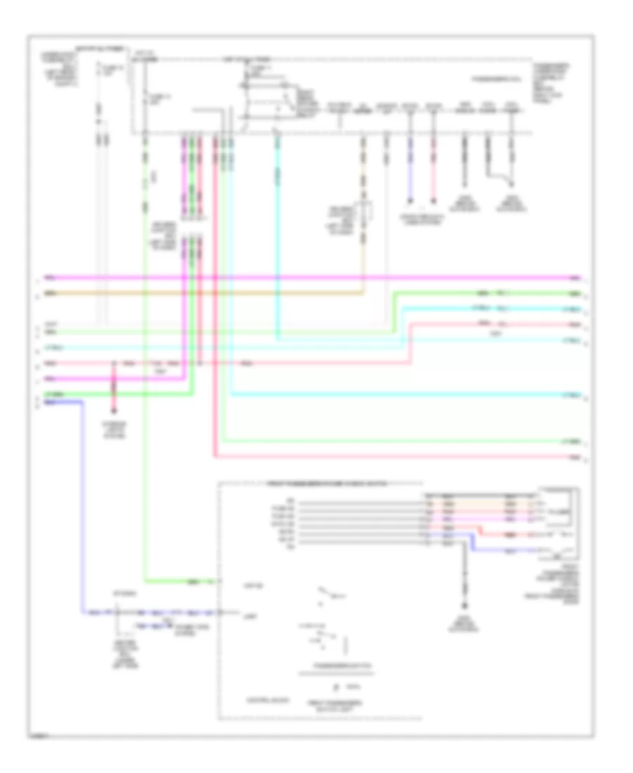 https://portal-diagnostov.com/license.html
Automotive Electricians Portal FZCO
Automotive Electricians Portal FZCO
https://portal-diagnostov.com/license.html
https://portal-diagnostov.com/license.html
Automotive Electricians Portal FZCO
Automotive Electricians Portal FZCOList of elements for Power Windows Wiring Diagram (2 of 3) for Honda Crosstour EX 2012:
- +b back up
- A18
- A20
- A21
- A26
- A28
- A29
- A31
- A34
- As dn
- As up
- B-can hi
- B-can lo
- C401
- C801
- C811
- Center junction box (under left side
- Computer data lines system
- Control block
- Driver's junction box (left side g3
- Driver's junction box (left side of dash)
- E14
- E15
- Front passenger's power window motor (middle of front passenger's door)
- Front passenger's power window switch
- Front passenger's switch light
- Fuse 11 20a
- Fuse 13 20a
- Fuse 15 10a
- G203 (behind glove box)
- G405 (behind glove box)
- Gnd (micu-s)
- H11
- H20
- H25
- H32
- Hot at all times
- Ig1 meter
- Interior lights system
- Micu p-gnd
- Micu s-gnd
- Of dash)
- P/w rr r rly cl-
- Passenger's micu
- Passenger's switch
- Passenger's under-dash fuse/relay box (behind right kick panel)
- Plsa as
- Plsb as
- Pnk
- Power tops system
- Pulser
- Red
- Right rear power window relay
- Svcc as
- Uart
- Under-hood fuse/relay box (left rear of engine compt)
- Vmp as
Power Windows Wiring Diagram (3 of 3) for Honda Crosstour EX 2012
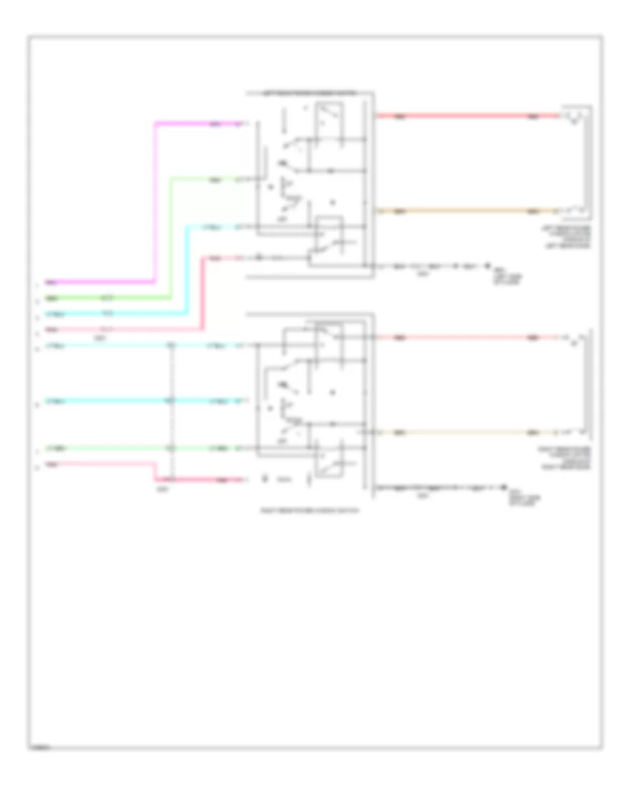 https://portal-diagnostov.com/license.html
Automotive Electricians Portal FZCO
Automotive Electricians Portal FZCO
https://portal-diagnostov.com/license.html
https://portal-diagnostov.com/license.html
Automotive Electricians Portal FZCO
Automotive Electricians Portal FZCOList of elements for Power Windows Wiring Diagram (3 of 3) for Honda Crosstour EX 2012:
- C821
- C831
- Down
- G601 (left side of floor)
- G701 (right side of floor)
- Left rear power window motor (middle of left rear door)
- Left rear power window switch
- Off
- Pnk
- Red
- Right rear power window motor (middle of right rear door)
- Right rear power window switch
RADIO
Premium Radio Wiring Diagram, with Navigation (1 of 4) for Honda Crosstour EX 2012
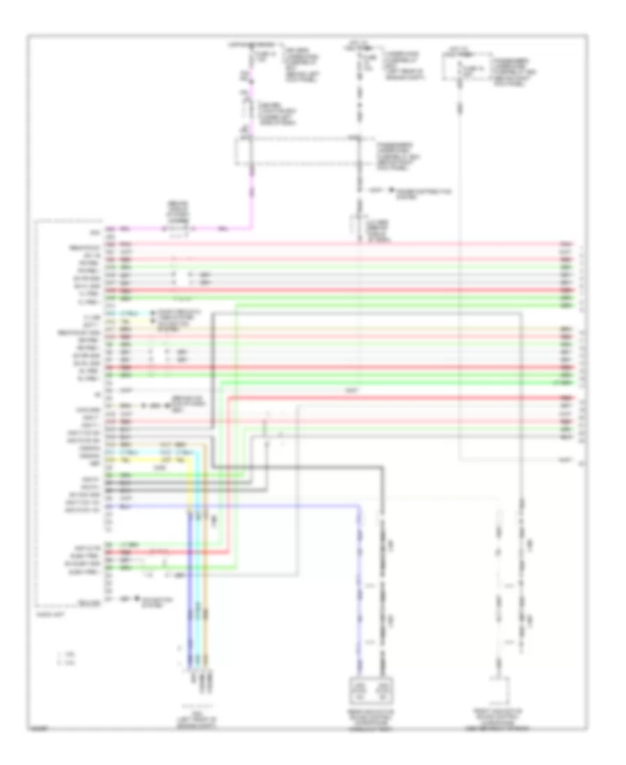 https://portal-diagnostov.com/license.html
Automotive Electricians Portal FZCO
Automotive Electricians Portal FZCO
https://portal-diagnostov.com/license.html
https://portal-diagnostov.com/license.html
Automotive Electricians Portal FZCO
Automotive Electricians Portal FZCOList of elements for Premium Radio Wiring Diagram, with Navigation (1 of 4) for Honda Crosstour EX 2012:
- (behind mid- dle of dash) g501
- (behind middle of dash) j/c c505
- 2.4l
- 3.5l
- A10
- A11
- A12
- A13
- A14
- A15
- A16
- A17
- A18
- A19
- A20
- A21
- A22
- A23
- A24
- A33
- Acc
- Amp mute
- Anc f +
- Anc f -
- Anc f mic +8v
- Anc f mic sh
- Anc r +
- Anc r -
- Anc r mic +8v
- Anc r mic sh
- Audio unit
- C10
- C11
- C12
- C13
- C14
- C15
- C16
- C306
- C403
- C406
- C407
- Center junction box (under left side of dash)
- Computer data lines system navigation system
- Cssama
- Cssamc
- D24
- Driver's under-dash fuse/relay box (behind left kick panel)
- Fl pre +
- Fl pre -
- Fr pre +
- Fr pre -
- Front anc/active sound control microphone (center front of roof)
- Fuse 10a
- Fuse 15 20a
- Fuse 18 7.5a
- Hot at all times
- Hot in acc or on
- J/c c506 (behind middle of dash)
- K line
- Main gnd
- Navigation system
- Nep
- Passenger's under-dash fuse/relay box (behind right kick panel)
- Pcm (left front of engine compt)
- Pnk
- Power distribution system
- Rear anc/active sound control microphone (middle of roof)
- Red
- Remote sw
- Remote sw gnd
- Rl pre +
- Rl pre -
- Rr pre +
- Rr pre -
- Scty -
- Sh anc gnd
- Sh fl gnd
- Sh fr gnd
- Sh rl gnd
- Sh rr gnd
- Sh subw gnd
- Subw pre +
- Subw pre -
- Sw +b
- Telm sig
- Under-hood fuse/relay box (left rear of engine compt)
Premium Radio Wiring Diagram, with Navigation (2 of 4) for Honda Crosstour EX 2012
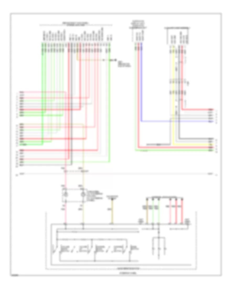 https://portal-diagnostov.com/license.html
Automotive Electricians Portal FZCO
Automotive Electricians Portal FZCO
https://portal-diagnostov.com/license.html
https://portal-diagnostov.com/license.html
Automotive Electricians Portal FZCO
Automotive Electricians Portal FZCOList of elements for Premium Radio Wiring Diagram, with Navigation (2 of 4) for Honda Crosstour EX 2012:
- (behind right kick panel) stereo amplifier
- (not used)
- A10
- A11
- A12
- A13
- A14
- A15
- A16
- A17
- A18
- A19
- A20
- A21
- A22
- A23
- A24
- Amp mute
- Anc f +
- Anc f -
- Anc r +
- Anc r -
- Audio remote switch
- Audio-hvac display unit/ audio-hvac sub display unit
- Aux det
- Aux gnd
- Aux lch
- Aux rch
- Aux sig gnd
- Auxiliary jack assembly
- C407
- Cable reel (a: in steering column) (c: in steering wheel)
- Channel down switch
- Channel up switch
- Duet cont
- Duet rx
- Duet tx
- Fl pre +
- Fl pre -
- Fr pre +
- Fr pre -
- G501 (behind mid- dle of dash)
- Gnd
- Interior lights system
- Mode switch
- Navigation system
- Pnk
- Red
- Rl pre +
- Rl pre -
- Rr pre +
- Rr pre -
- Sh fl gnd
- Sh fr gnd
- Sh rl gnd
- Sh rr gnd
- Sh subw gnd
- Steering wheel
- Subw pre +
- Subw pre -
- Sw +b
- Volume down switch
- Volume up switch
Premium Radio Wiring Diagram, with Navigation (3 of 4) for Honda Crosstour EX 2012
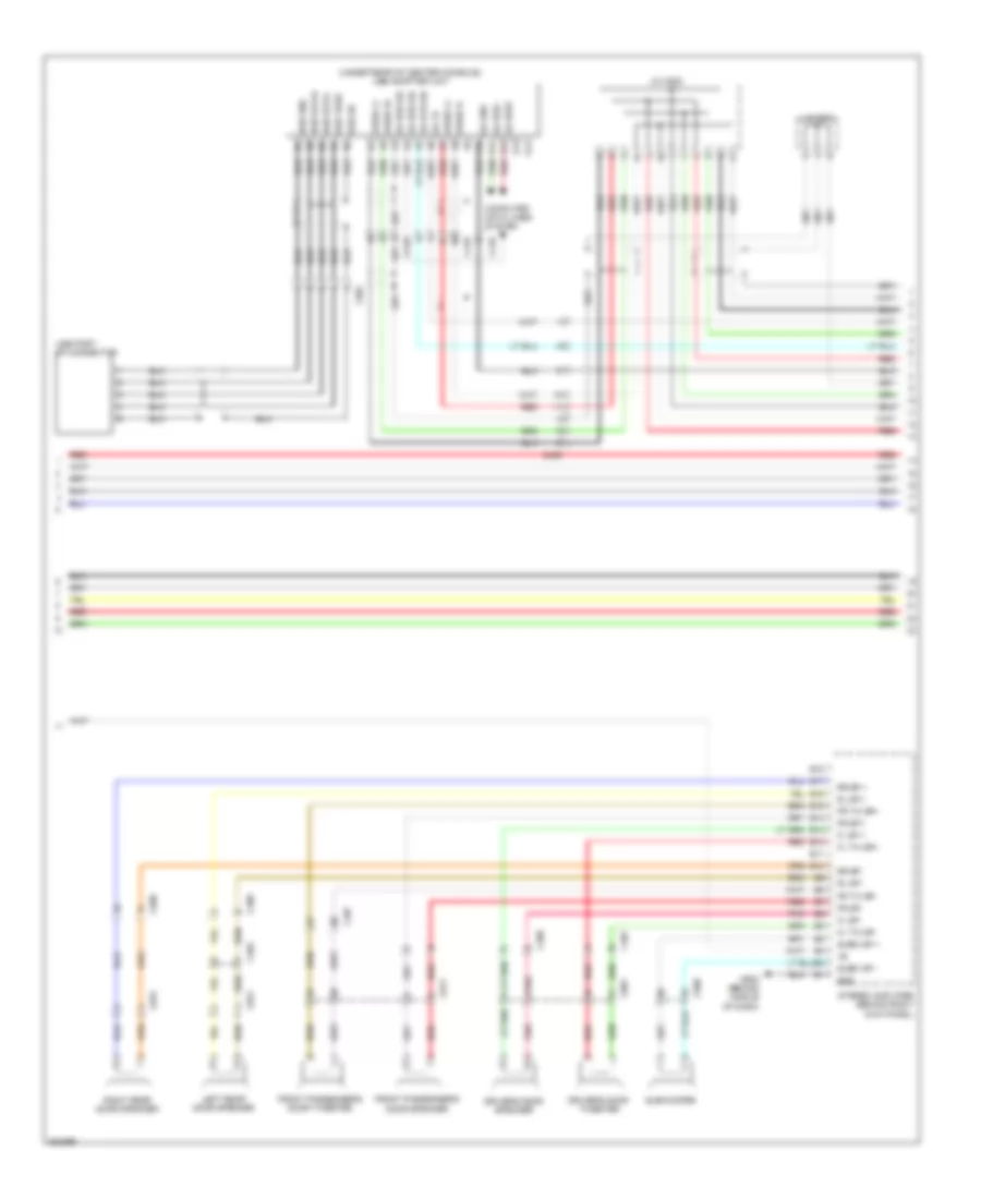 https://portal-diagnostov.com/license.html
Automotive Electricians Portal FZCO
Automotive Electricians Portal FZCO
https://portal-diagnostov.com/license.html
https://portal-diagnostov.com/license.html
Automotive Electricians Portal FZCO
Automotive Electricians Portal FZCOList of elements for Premium Radio Wiring Diagram, with Navigation (3 of 4) for Honda Crosstour EX 2012:
- (under rear of center console) usb adapter unit
- A13
- A14
- Audio l+ a1
- Audio l+ a7
- Audio r+ a2
- Audio r- a8
- B10
- B11
- B12
- B13
- B14
- B15
- B16
- B17
- B18
- C402
- C407
- C408
- C409
- C410
- C508
- C801
- C811
- C821
- C831
- C901
- Computer data lines system
- Driver's door speaker
- Driver's door tweeter
- Fl sp +
- Fl sp-
- Fl tw sp+
- Fl tw sp-
- Fr sp +
- Fr sp-
- Fr tw sp+
- Fr tw sp-
- Front passenger's door speaker
- Front passenger's door tweeter
- G502 (behind middle of dash)
- Ga +b a6
- Ga bus sh a3
- Ga bus sh a4
- Ga bus+ a12
- Ga bus- a11
- Ga gnd a10
- Ga sys on a5
- Gnd
- J/c c501
- J/c c502
- Left rear door speaker
- Pnk
- Red
- Right rear door speaker
- Rl sp +
- Rl sp -
- Rr sp +
- Rr sp -
- Stereo amplifier (behind right kick panel)
- Subw sp +
- Subw sp -
- Subwoofer
- Usb data+ b2
- Usb data- b3
- Usb gnd b1
- Usb port 5p connector
- Usb sh b5
- Usb vbus b4
Premium Radio Wiring Diagram, with Navigation (4 of 4) for Honda Crosstour EX 2012
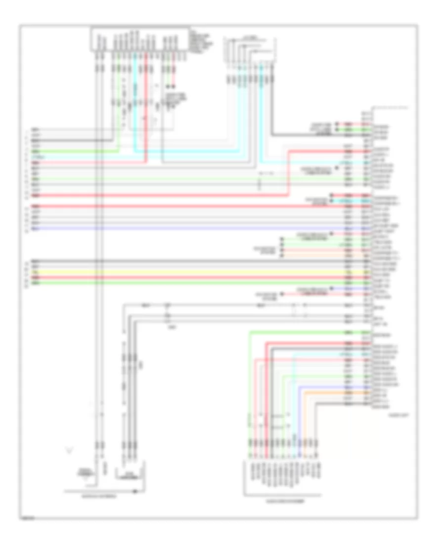 https://portal-diagnostov.com/license.html
Automotive Electricians Portal FZCO
Automotive Electricians Portal FZCO
https://portal-diagnostov.com/license.html
https://portal-diagnostov.com/license.html
Automotive Electricians Portal FZCO
Automotive Electricians Portal FZCOList of elements for Premium Radio Wiring Diagram, with Navigation (4 of 4) for Honda Crosstour EX 2012:
- 6cd +b
- 6cd audio l+
- 6cd audio l-
- 6cd audio r+
- 6cd audio r-
- 6cd audio sh
- 6cd bus sh
- 6cd bus+
- 6cd bus-
- 6cd gnd
- 6cd ill+
- 6cd ill-
- 6cd sys on
- A10
- A11
- A12
- A13
- A14
- Am/fm/xm antenna
- Ant +b
- Audio disc changer
- Audio l+
- Audio l-
- Audio r+
- Audio r-
- Audio sh
- Audio unit
- Aux det
- Aux gnd
- Aux lch
- Aux rch
- Aux sh gnd
- Aux sig gnd
- B can h
- B can l
- B10
- B11
- B12
- B13
- B14
- B15
- B16
- B17
- B18
- B19
- B20
- C508
- C551
- C561
- Compass rx +
- Compass rx -
- Compass tx +
- Compass tx -
- Computer data lines system
- Duet cont
- Duet rx
- Duet tx
- E10
- E11
- E12
- E13
- E14
- G10
- G11
- G12
- G13
- G14
- Ga +b
- Ga bus sh
- Ga bus+
- Ga bus-
- Ga gnd
- Ga sys on
- Hfl mute
- J/c c501
- Navigation system
- Pnk
- Red
- Rf in
- Rf sh
- Sh duet gnd
- Sh sat
- Signal antenna
- Sub amplifer
- Telm sig+
- Telm sig-
- Ter sat
- Xm receiver (behind right rear side trim panel)
Premium Radio Wiring Diagram, without Navigation (1 of 4) for Honda Crosstour EX 2012
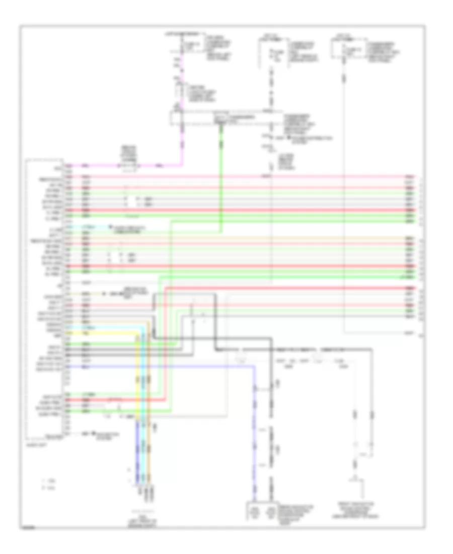 https://portal-diagnostov.com/license.html
Automotive Electricians Portal FZCO
Automotive Electricians Portal FZCO
https://portal-diagnostov.com/license.html
https://portal-diagnostov.com/license.html
Automotive Electricians Portal FZCO
Automotive Electricians Portal FZCOList of elements for Premium Radio Wiring Diagram, without Navigation (1 of 4) for Honda Crosstour EX 2012:
- (behind mid- dle of dash) g501
- (behind middle of dash) j/c c505
- 2.4l
- 3.5l
- A10
- A11
- A12
- A13
- A14
- A15
- A16
- A17
- A18
- A19
- A20
- A21
- A22
- A23
- A24
- A33
- Acc
- Amp mute
- Anc f +
- Anc f -
- Anc f mic +8v
- Anc f mic sh
- Anc r +
- Anc r -
- Anc r mic +8v
- Anc r mic sh
- Audio unit
- C10
- C11
- C12
- C13
- C14
- C15
- C16
- C306
- C403
- C406
- C407
- Center junction box (under left side of dash)
- Computer data lines system
- Cssama
- Cssamc
- D23
- D24
- Driver's under-dash fuse/relay box (behind left kick panel)
- Fl pre +
- Fl pre -
- Fr pre +
- Fr pre -
- Front anc/active sound control microphone (center front of roof)
- Fuse 10a
- Fuse 15 20a
- Fuse 18 7.5a
- Hot at all times
- Hot in acc or on
- J/c c506 (behind middle of dash)
- K line
- Main gnd
- Navigation system
- Nep
- P16
- Passenger's micu
- Passenger's under-dash fuse/relay box (behind right kick panel)
- Pcm (left front of engine compt)
- Pnk
- Power distribution system
- Rear anc/active sound control microphone (middle of roof)
- Red
- Remote sw
- Remote sw gnd
- Rl pre +
- Rl pre -
- Rr pre +
- Rr pre -
- Scty -
- Scty radio
- Sh anc gnd
- Sh fl gnd
- Sh fr gnd
- Sh rl gnd
- Sh rr gnd
- Sh subw gnd
- Subw pre +
- Subw pre -
- Sw +b
- Telm sig
- Under-hood fuse/relay box (left rear of engine compt)
Premium Radio Wiring Diagram, without Navigation (2 of 4) for Honda Crosstour EX 2012
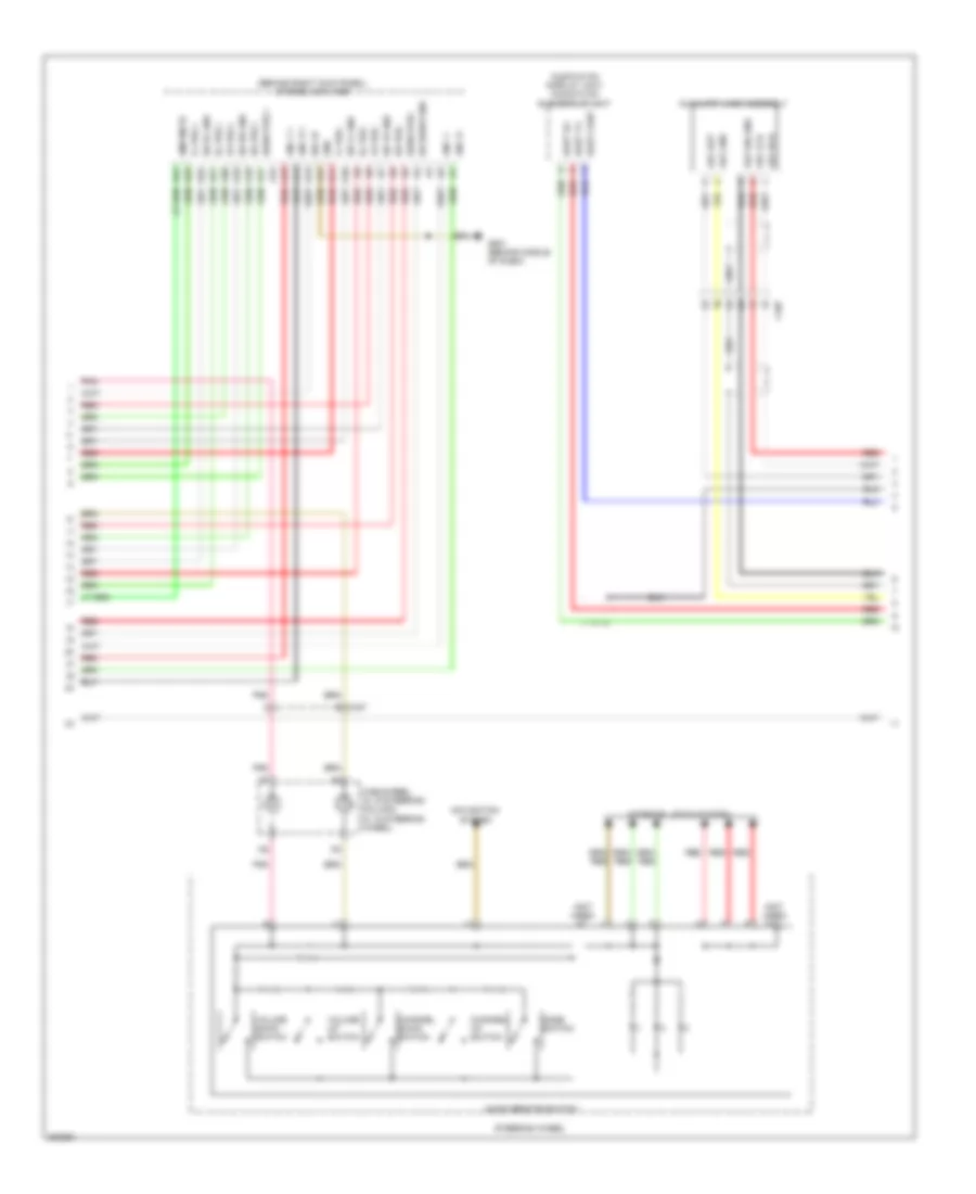 https://portal-diagnostov.com/license.html
Automotive Electricians Portal FZCO
Automotive Electricians Portal FZCO
https://portal-diagnostov.com/license.html
https://portal-diagnostov.com/license.html
Automotive Electricians Portal FZCO
Automotive Electricians Portal FZCOList of elements for Premium Radio Wiring Diagram, without Navigation (2 of 4) for Honda Crosstour EX 2012:
- (behind right kick panel) stereo amplifier
- (not used)
- A10
- A11
- A12
- A13
- A14
- A15
- A16
- A17
- A18
- A19
- A20
- A21
- A22
- A23
- A24
- Amp mute
- Anc f +
- Anc f -
- Anc r +
- Anc r -
- Audio remote switch
- Audio-hvac display unit/ audio-hvac sub display unit
- Aux det
- Aux gnd
- Aux lch
- Aux rch
- Aux sig gnd
- Auxiliary jack assembly
- C407
- Cable reel (a: in steering column) (c: in steering wheel)
- Channel down switch
- Channel up switch
- Duet cont
- Duet rx
- Duet tx
- Fl pre +
- Fl pre -
- Fr pre +
- Fr pre -
- G501 (behind middle of dash)
- Gnd
- Interior lights system
- Mode switch
- Navigation system
- Pnk
- Red
- Rl pre +
- Rl pre -
- Rr pre +
- Rr pre -
- Sh fl gnd
- Sh fr gnd
- Sh rl gnd
- Sh rr gnd
- Sh subw gnd
- Steering wheel
- Subw pre +
- Subw pre -
- Sw +b
- Volume down switch
- Volume up switch
Premium Radio Wiring Diagram, without Navigation (3 of 4) for Honda Crosstour EX 2012
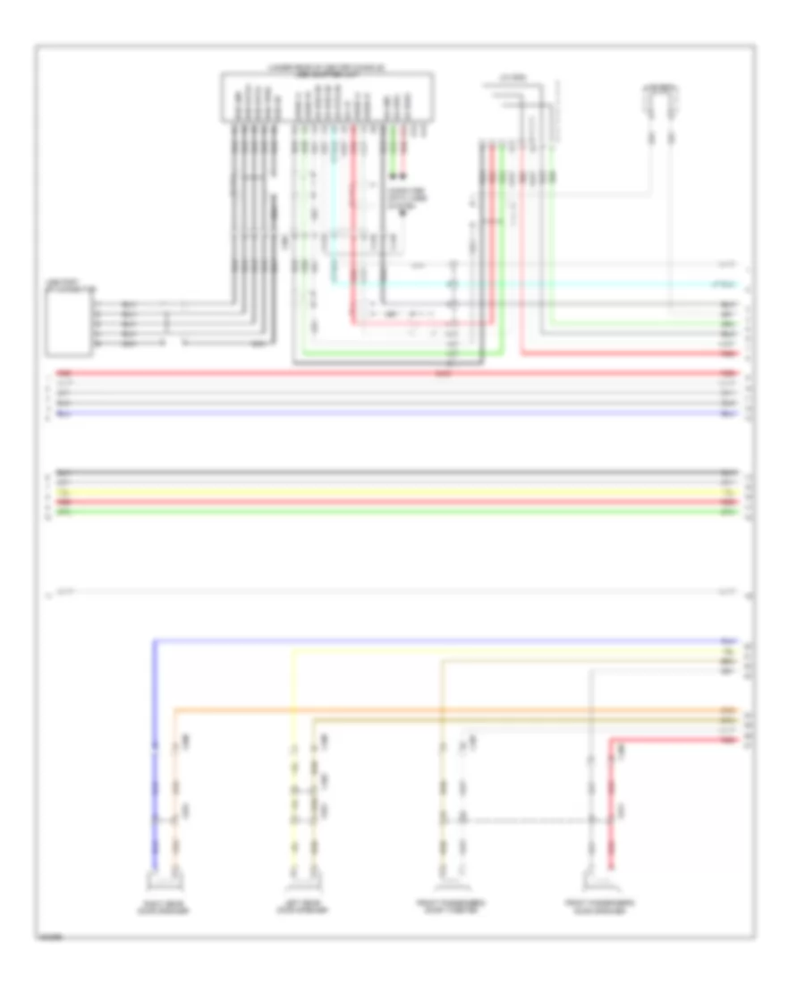 https://portal-diagnostov.com/license.html
Automotive Electricians Portal FZCO
Automotive Electricians Portal FZCO
https://portal-diagnostov.com/license.html
https://portal-diagnostov.com/license.html
Automotive Electricians Portal FZCO
Automotive Electricians Portal FZCOList of elements for Premium Radio Wiring Diagram, without Navigation (3 of 4) for Honda Crosstour EX 2012:
- (under rear of center console) usb adapter unit
- A13
- A14
- Audio l+ a1
- Audio l+ a7
- Audio r+ a2
- Audio r- a8
- C402
- C407
- C408
- C409
- C410
- C508
- C811
- C821
- C831
- C901
- Computer data lines system
- Front passenger's door speaker
- Front passenger's door tweeter
- Ga +b a6
- Ga bus sh a3
- Ga bus sh a4
- Ga bus+ a12
- Ga bus- a11
- Ga gnd a10
- Ga sys on a5
- J/c c501
- J/c c502
- Left rear door speaker
- Nca
- Red
- Right rear door speaker
- Usb data+ b2
- Usb data- b3
- Usb gnd b1
- Usb port 5p connector
- Usb sh b5
- Usb vbus b4
Premium Radio Wiring Diagram, without Navigation (4 of 4) for Honda Crosstour EX 2012
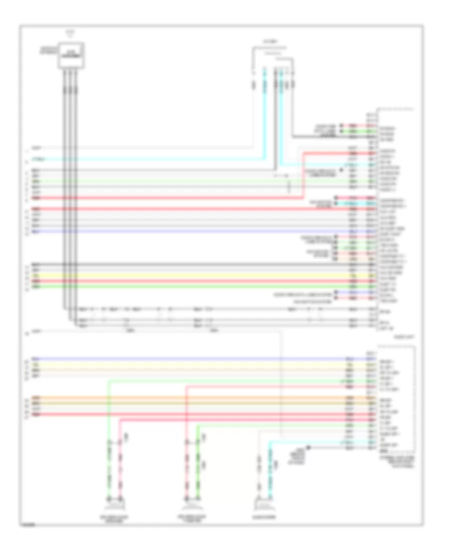 https://portal-diagnostov.com/license.html
Automotive Electricians Portal FZCO
Automotive Electricians Portal FZCO
https://portal-diagnostov.com/license.html
https://portal-diagnostov.com/license.html
Automotive Electricians Portal FZCO
Automotive Electricians Portal FZCOList of elements for Premium Radio Wiring Diagram, without Navigation (4 of 4) for Honda Crosstour EX 2012:
- Am/fm/xm antenna
- Ant +b
- Audio l+
- Audio l-
- Audio r+
- Audio r-
- Audio sh
- Audio unit
- Aux det
- Aux gnd
- Aux lch
- Aux rch
- Aux sh gnd
- Aux sig gnd
- B can h
- B can l
- B10
- B11
- B12
- B13
- B14
- B15
- B16
- B17
- B18
- B19
- B20
- C407
- C408
- C508
- C551
- C561
- C801
- Compass rx +
- Compass rx -
- Compass tx +
- Compass tx -
- Computer data lines system
- Driver's door speaker
- Driver's door tweeter
- Duet cont
- Duet rx
- Duet tx
- E10
- E11
- E12
- E13
- E14
- Fl sp +
- Fl sp-
- Fl tw sp+
- Fl tw sp-
- Fr sp +
- Fr sp-
- Fr tw sp+
- Fr tw sp-
- G502 (behind middle of dash)
- Ga +b
- Ga bus sh
- Ga bus+
- Ga bus-
- Ga gnd
- Ga sys on
- Gnd
- Hfl mute
- J/c c501
- Navigation system
- Pnk
- Red
- Rf in
- Rf sh
- Rl sp +
- Rl sp -
- Rr sp +
- Rr sp -
- Sh duet gnd
- Stereo amplifier (behind right kick panel)
- Sub amplifer
- Subw sp +
- Subw sp -
- Subwoofer
- Telm sig+
- Telm sig-
SHIFT INTERLOCK
Shift Interlock Wiring Diagram for Honda Crosstour EX 2012
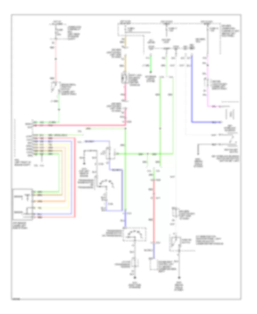 https://portal-diagnostov.com/license.html
Automotive Electricians Portal FZCO
Automotive Electricians Portal FZCO
https://portal-diagnostov.com/license.html
https://portal-diagnostov.com/license.html
Automotive Electricians Portal FZCO
Automotive Electricians Portal FZCOList of elements for Shift Interlock Wiring Diagram for Honda Crosstour EX 2012:
- (behind middle of dash)
- 2.4l
- 3.5l
- A/t gear position indicator panel light/ park pin switch (under center console)
- A11
- A16
- A18
- A19
- A24
- A25
- A26
- A27
- A35
- A36
- A42
- Acc key lock
- App sensor (under left side of dash)
- Apsa
- Apsb
- Atp-p
- Atpp
- B14
- B35
- Bksw
- Brake pedal position switch (under left side of dash)
- C101
- C106
- C306
- C411
- C701
- Center junction box (under left side of dash)
- Driver's junction box (left side of dash)
- Driver's micu
- Driver's under-dash
- Exterior lights system
- F14
- F23
- Fuse 17 7.5a
- Fuse 18 7.5a
- Fuse 20a
- Fuse 5 7.5a
- Fuse/relay box (behind left kick panel)
- G101 (right side of engine)
- G101 (top left rear of engine)
- G403
- Hot at all times
- Hot in acc or on
- Hot in on or start
- Ig 1 meter
- Ignition key switch
- J/c c101
- J/c c106 (transmission housing)
- Key interlock solenoid
- Key interlock solenoid/ ignition key switch/ ignition key light
- Key lock sol
- Key sw
- P-pin sw
- P16
- Park pin switch
- Pcm (left front of engine compt)
- Pnk
- Power seat control unit (w/ memory) (under driver's seat)
- Q13
- Q17
- Q18
- Red
- Sensor
- Sg4
- Sg5
- Shift lock solenoid (under center console)
- Sls
- Stop sw
- Transmission range switch (on transmission)
- Under-hood fuse/relay box (left rear of engine compt)
- Vcc4
- Vcc5
STARTING/CHARGING
2.4L
2.4L, Charging Wiring Diagram for Honda Crosstour EX 2012
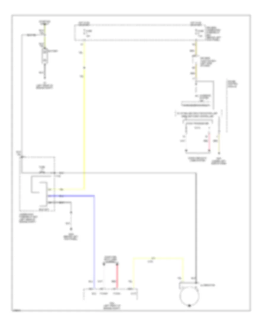 https://portal-diagnostov.com/license.html
Automotive Electricians Portal FZCO
Automotive Electricians Portal FZCO
https://portal-diagnostov.com/license.html
https://portal-diagnostov.com/license.html
Automotive Electricians Portal FZCO
Automotive Electricians Portal FZCOList of elements for 2.4L, Charging Wiring Diagram for Honda Crosstour EX 2012:
- A24
- Altc
- Alternator
- Area network controller
- B45
- Battery
- C102
- Charging system ind
- Computer data lines system
- Driver's junction box (left side of dash)
- Driver's under-dash fuse/relay box (behind left kick panel)
- Eld
- Eld unit
- F-can transceiver
- F-canh
- F-canl
- Fuse 1-1 100a
- Fuse 15a
- Fuse 7.5a
- G1 (left front of engine compt)
- G302 (behind left kick panel)
- G401 (under left side of dash)
- Gauge control module
- Hot in on or start
- Pcm (left front of engine compt)
- Red
- Starting circuit
- Sv stabilize circuite/controller
- T102
- Under-hood fuse/relay box (left rear of engine compt)
- Warning drive circuit
2.4L, Starting Wiring Diagram for Honda Crosstour EX 2012
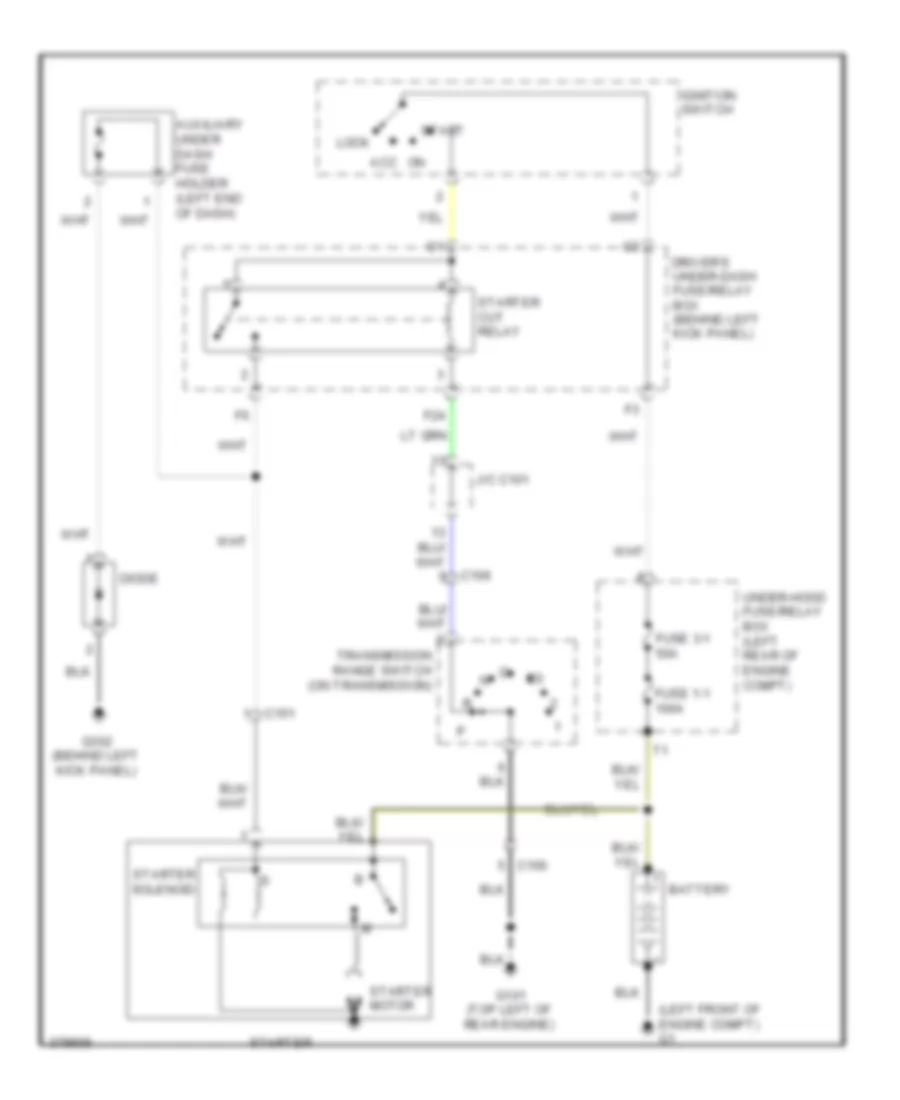 https://portal-diagnostov.com/license.html
Automotive Electricians Portal FZCO
Automotive Electricians Portal FZCO
https://portal-diagnostov.com/license.html
https://portal-diagnostov.com/license.html
Automotive Electricians Portal FZCO
Automotive Electricians Portal FZCOList of elements for 2.4L, Starting Wiring Diagram for Honda Crosstour EX 2012:
- (left front of engine compt) g1
- Acc
- Auxiliary under dash fuse holder (left end of dash)
- Battery
- C106
- C151
- Diode
- Driver's under-dash fuse/relay box (behind left kick panel)
- F24
- Fuse 1-1 100a
- Fuse 3-1 50a
- G101 (top left of rear engine)
- G302 (behind left kick panel)
- Ignition switch
- J/c c101
- Lock
- Start
- Starter
- Starter cut relay
- Starter motor
- Starter solenoid
- Transmission range switch (on transmission)
- Under-hood fuse/relay box (left rear of engine compt)
3.5L
3.5L, Charging Wiring Diagram for Honda Crosstour EX 2012
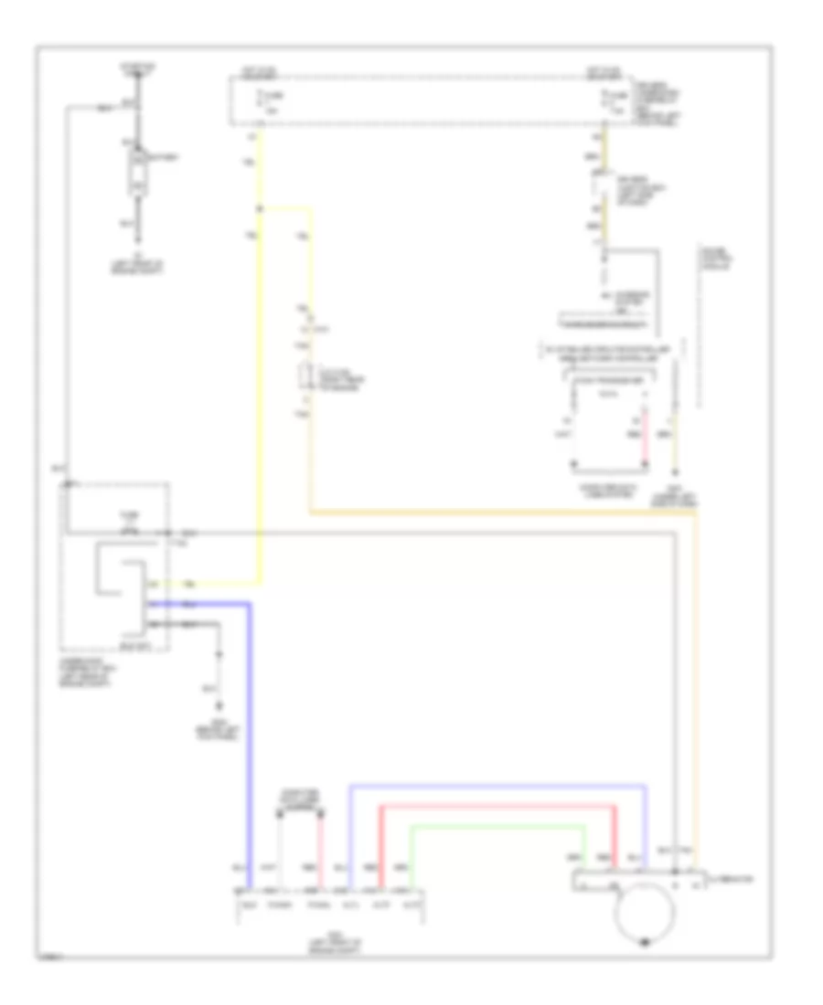 https://portal-diagnostov.com/license.html
Automotive Electricians Portal FZCO
Automotive Electricians Portal FZCO
https://portal-diagnostov.com/license.html
https://portal-diagnostov.com/license.html
Automotive Electricians Portal FZCO
Automotive Electricians Portal FZCOList of elements for 3.5L, Charging Wiring Diagram for Honda Crosstour EX 2012:
- A10
- A48
- A49
- Altc
- Alternator
- Altf
- Altl
- Area network controller
- Battery
- C101
- C42
- C43
- C44
- Charging system ind
- Computer data lines system
- Driver's junction box (left side of dash)
- Driver's under-dash fuse/relay box (behind left kick panel)
- Eld
- Eld unit
- F-can transceiver
- F-canh
- F-canl
- Fuse 1-1 120a
- Fuse 15a
- Fuse 7.5a
- G1 (left front of engine compt)
- G302 (behind left kick panel)
- G401 (under left side of dash)
- Gauge control module
- Hot in on or start
- J/c c105 (right rear of engine)
- Pcm (left front of engine compt)
- Red
- Starting circuit
- Sv stabilize circuite/controller
- T102
- Tan
- Under-hood fuse/relay box (left rear of engine compt)
- Warning drive circuit
3.5L, Starting Wiring Diagram for Honda Crosstour EX 2012
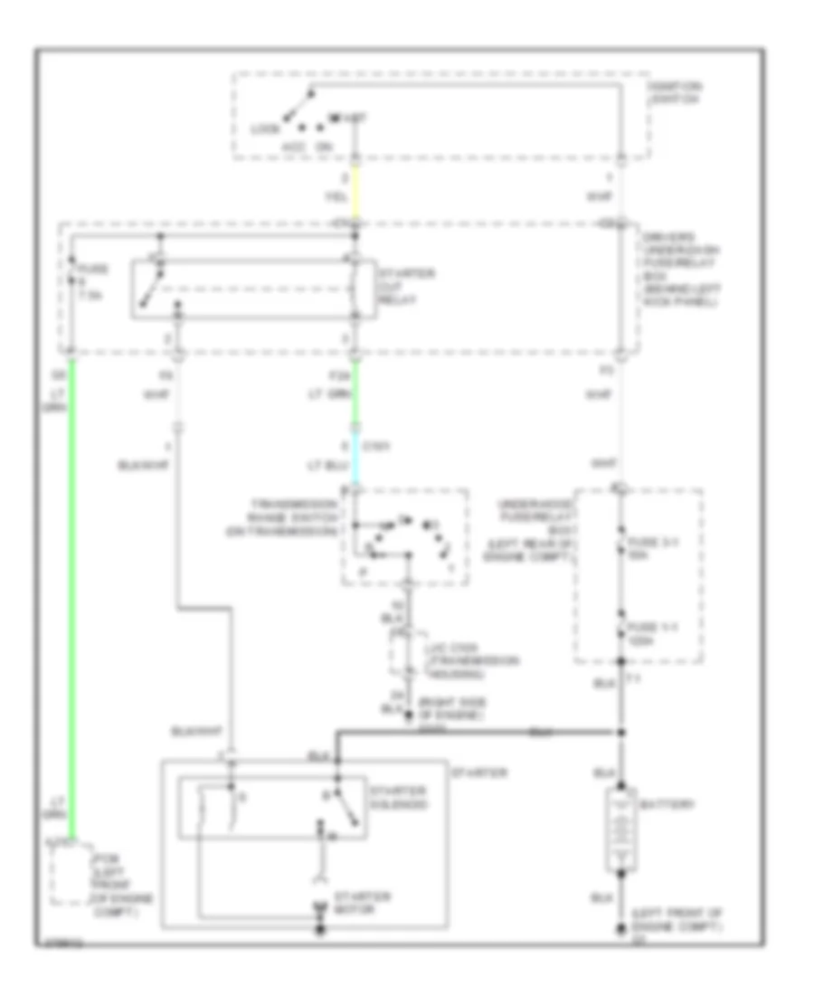 https://portal-diagnostov.com/license.html
Automotive Electricians Portal FZCO
Automotive Electricians Portal FZCO
https://portal-diagnostov.com/license.html
https://portal-diagnostov.com/license.html
Automotive Electricians Portal FZCO
Automotive Electricians Portal FZCOList of elements for 3.5L, Starting Wiring Diagram for Honda Crosstour EX 2012:
- (left front of engine compt) g1
- (right side of engine) g101
- A31
- Acc
- Battery
- C101
- Driver's under-dash fuse/relay box (behind left kick panel)
- F24
- Fuse 1-1 120a
- Fuse 3-1 50a
- Fuse 7.5a
- Ignition switch
- J/c c106 (transmission housing)
- Lock
- Pcm (left front of engine compt)
- Start
- Starter
- Starter cut relay
- Starter motor
- Starter solenoid
- Transmission range switch (on transmission)
- Under-hood fuse/relay box (left rear of engine compt)
SUPPLEMENTAL RESTRAINTS
Supplemental Restraints Wiring Diagram (1 of 3) for Honda Crosstour EX 2012
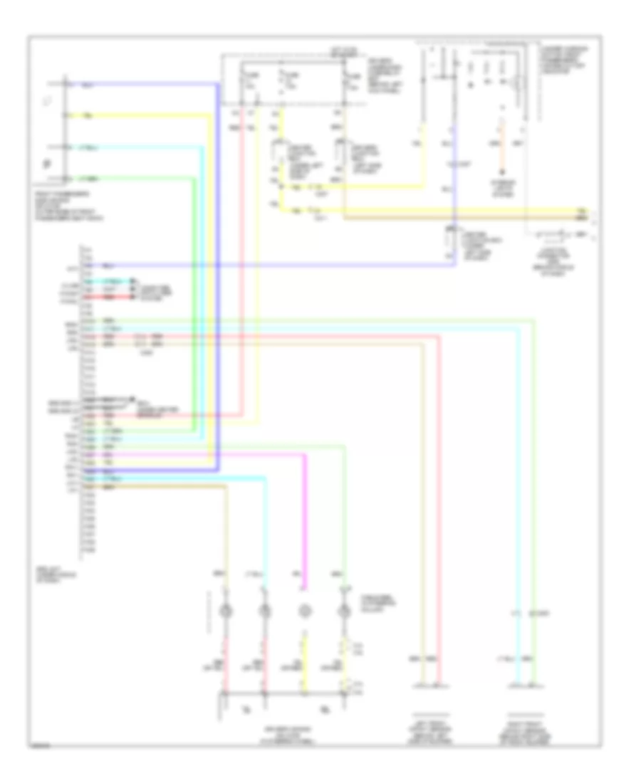 https://portal-diagnostov.com/license.html
Automotive Electricians Portal FZCO
Automotive Electricians Portal FZCO
https://portal-diagnostov.com/license.html
https://portal-diagnostov.com/license.html
Automotive Electricians Portal FZCO
Automotive Electricians Portal FZCOList of elements for Supplemental Restraints Wiring Diagram (1 of 3) for Honda Crosstour EX 2012:
- 2.4l
- 3.5l
- A10
- A11
- A12
- A13
- A14
- A15
- A16
- A17
- A18
- A19
- A20
- A21
- A22
- A23
- A24
- A25
- A26
- A27
- A28
- A29
- A30
- A31
- A32
- A33
- A34
- A35
- A36
- A37
- A38
- A39
- C203
- C305
- C407
- C411
- Cable reel (in steering column)
- Center junction box (under left side of dash)
- Computer data lines system
- Driver's air bag inflator (in steering wheel)
- Driver's junction box (left side of dash)
- Driver's under-dash fuse/relay box (behind left kick panel)
- F-canh
- F-canl
- Front passenger's side air bag inflator (outer edge of front passenger's seat back)
- Fuse 10a
- Fuse 7.5a
- G404 (under center console)
- Hazard warning switch/ front passenger's air bag cut-off indicator
- Hot in on or start
- Interior lights system
- Junction connector c505 (behind middle of dash)
- K-line
- La1+
- La1-
- La2+
- La2-
- Left front impact sensor (behind left side of bumper)
- Lfs+
- Lfs-
- Ptt
- Ra1+
- Ra1-
- Ra2+
- Ra2-
- Red
- Rfs+
- Rfs-
- Right front impact sensor (behind right side of front bumper)
- Srs gnd (1)
- Srs gnd (2)
- Srs unit (under middle of dash)
Supplemental Restraints Wiring Diagram (2 of 3) for Honda Crosstour EX 2012
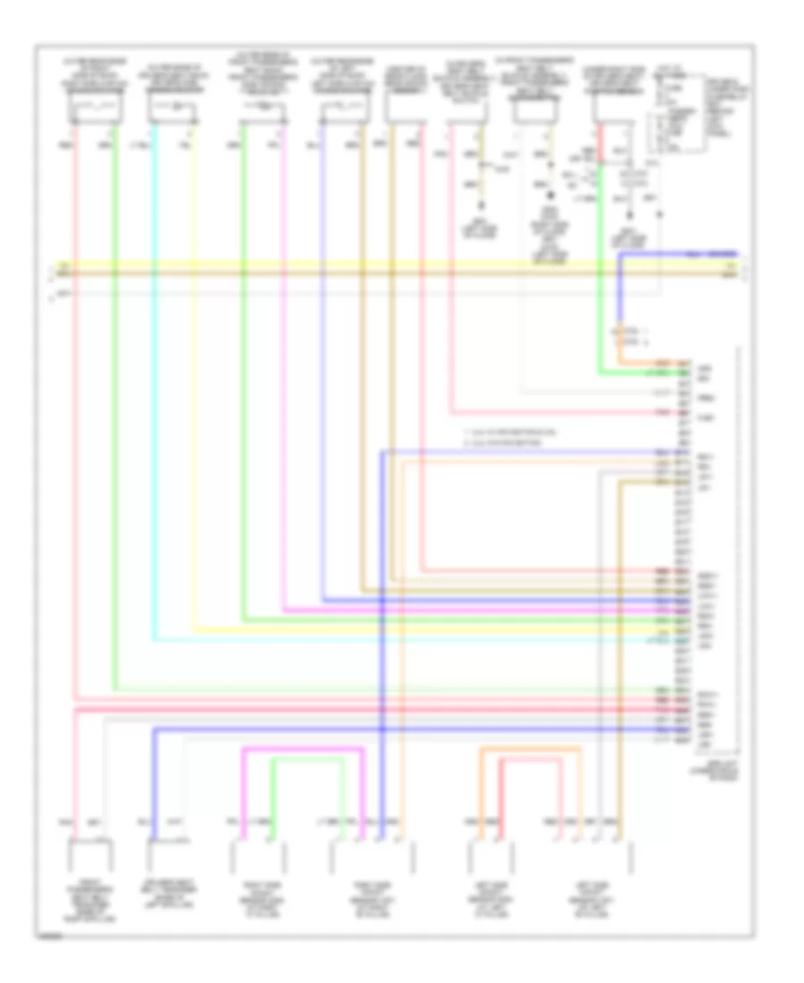 https://portal-diagnostov.com/license.html
Automotive Electricians Portal FZCO
Automotive Electricians Portal FZCO
https://portal-diagnostov.com/license.html
https://portal-diagnostov.com/license.html
Automotive Electricians Portal FZCO
Automotive Electricians Portal FZCOList of elements for Supplemental Restraints Wiring Diagram (2 of 3) for Honda Crosstour EX 2012:
- (center of rear floor) rear safing sensor
- (in driver's seat belt buckle assembly) driver's seat belt buckle switch
- (in front passenger's seat belt buckle assembly) front passenger's seat belt buckle switch
- (outer edge of driver's seat back) driver's side air bag inflator
- (outer edge of front passenger's seat back) front passenger's side air bag inflator
- (outer rear edge of left side of roof) left side curtain air bag inflator
- (outer rear edge of right side of roof) right side curtain air bag inflator
- (under right side of driver's seat) driver's seat position sensor
- 2.4l w/ navigation & 3.5l
- 2.4l w/o navigation
- 4wd
- B10
- B11
- B12
- B13
- B14
- B15
- B16
- B17
- B18
- B19
- B20
- B21
- B22
- B23
- B24
- B25
- B26
- B27
- B28
- B29
- B30
- B31
- B32
- B33
- B34
- B35
- B36
- B37
- B38
- B39
- C701
- C702
- D14
- Driver's seat belt tensioner (base of left b-pillar)
- Driver,s under dash fuse/relay box (behind left kick panel)
- Ex-l
- Flbc
- Frbc
- Front passenger's seat belt tensioner (base of right b-pillar)
- Fuse 10a
- G801 (left side of floor)
- G802 (2wd) (right side of floor) g801 (4wd) (left side of floor)
- Hot at all times
- Lca1+
- Lca1-
- Left side impact sensor (1st) (at left "b" pillar)
- Left side impact sensor (2nd) (at left "c" pillar)
- Lrp+
- Lrp-
- Ls1+
- Ls1-
- Lsa+
- Lsa-
- Ods
- Passen- ger's micu fuse 7.5a
- Pnk
- Rca1+
- Rca1-
- Red
- Right side impact sensor (1st) (at right "b" pillar)
- Right side impact sensor (2nd) (at right "c" pillar)
- Rrp+
- Rrp-
- Rs1+
- Rs1-
- Rsa+
- Rsa-
- Srs unit (under middle of dash)
- Ss+
- Sss1+
- Sss1-
Supplemental Restraints Wiring Diagram (3 of 3) for Honda Crosstour EX 2012
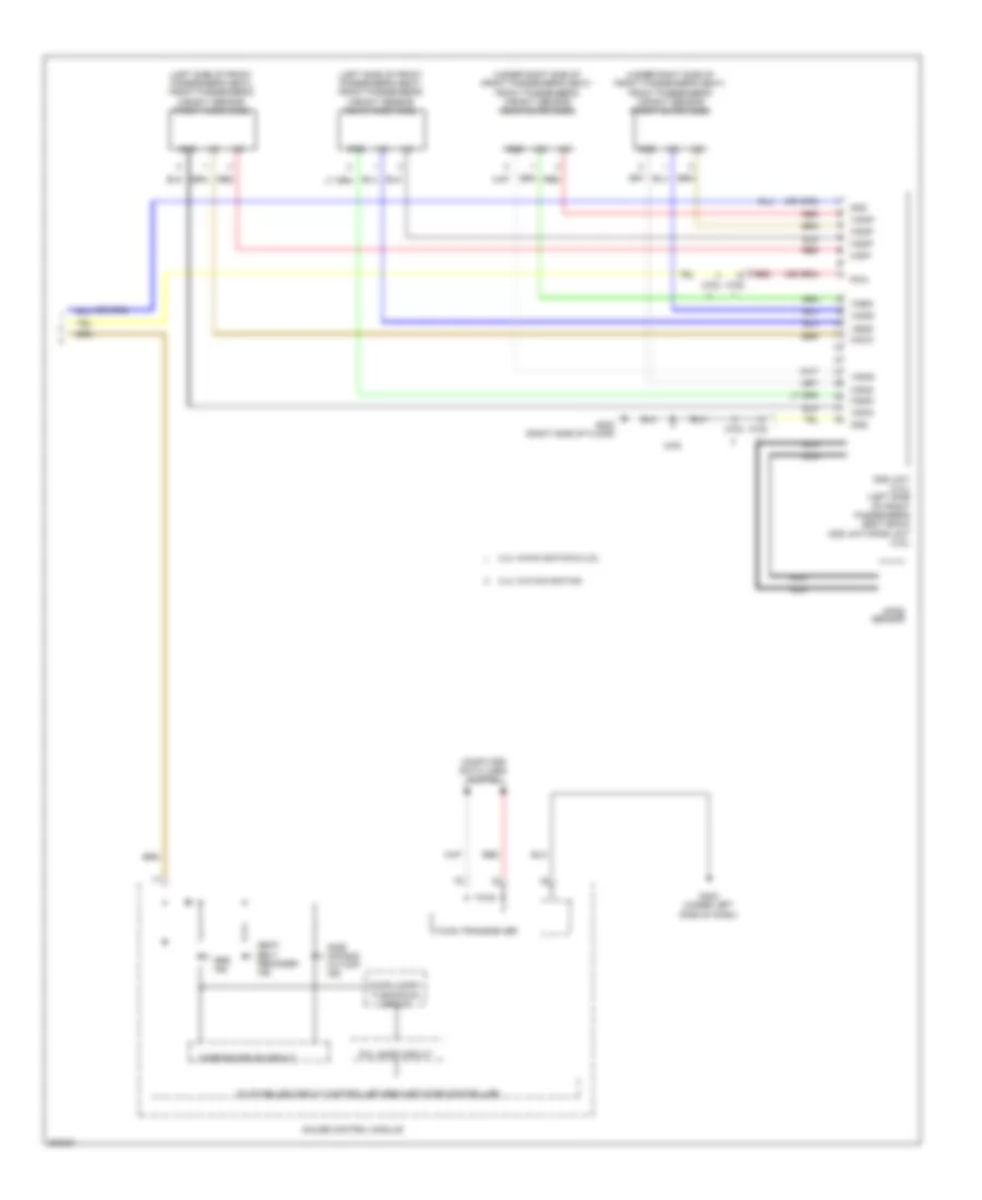 https://portal-diagnostov.com/license.html
Automotive Electricians Portal FZCO
Automotive Electricians Portal FZCO
https://portal-diagnostov.com/license.html
https://portal-diagnostov.com/license.html
Automotive Electricians Portal FZCO
Automotive Electricians Portal FZCOList of elements for Supplemental Restraints Wiring Diagram (3 of 3) for Honda Crosstour EX 2012:
- (left side of front passenger's seat) front passenger's weight sensor (front inner side)
- (left side of front passenger's seat) front passenger's weight sensor (rear inner side)
- (under right side of front passenger's seat) front passenger's weight sensor (front outer side)
- (under right side of front passenger's seat) front passenger's weight sensor (rear outer side)
- 2.4l w/navigation & 3.5l
- 2.4l w/o navigation
- 4wd
- 5v stabilize circuit controller area network controller
- C702
- Compulsory turning-on circut
- Computer data lines system
- F-can transceiver
- Fail safe circuit
- G402 (under left side of dash)
- G802 (right side of floor)
- Gauge control module
- Gnd
- Nca
- Ods
- Ods unit (2.4l) (left side of front passenger's seat back) ods unit/opds unit (3.5l)
- Opds sensor
- Pow
- Red
- Seat belt reminder ind
- Side air bag cut-off ind
- Srs ind
- Warning drive circuit
- Ws1d
- Ws1g
- Ws2d
- Ws2g
- Ws2p
- Ws3d
- Ws3g
- Ws3p
- Ws4d
- Ws4g
- Ws4p
- Wsip
TRANSMISSION
2.4L
2.4L, Transmission Wiring Diagram (1 of 2) for Honda Crosstour EX 2012
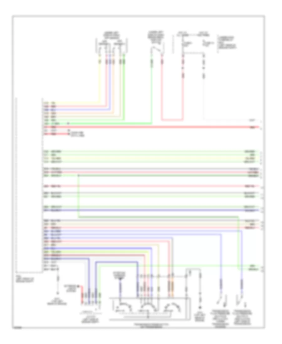 https://portal-diagnostov.com/license.html
Automotive Electricians Portal FZCO
Automotive Electricians Portal FZCO
https://portal-diagnostov.com/license.html
https://portal-diagnostov.com/license.html
Automotive Electricians Portal FZCO
Automotive Electricians Portal FZCOList of elements for 2.4L, Transmission Wiring Diagram (1 of 2) for Honda Crosstour EX 2012:
- (under left side of dash) app sensor
- (under left side of dash) brake pedal position switch
- A18
- A19
- A25
- A26
- A35
- A36
- A42
- App sensor 1
- App sensor 2
- B10
- B11
- B13
- B14
- B15
- B16
- B17
- B18
- B19
- B21
- B22
- B25
- B26
- B28
- B29
- B34
- B35
- B38
- B40
- B48
- C106
- C11
- C13
- C14
- C22
- Computer data lines
- Exterior lights system
- Fuse 15 10a
- Fuse 8 20a
- G101 (top left rear of engine)
- Hot at all times
- J/c c101 (left side of engine compt)
- Pcm (left front of engine compt)
- Pnk
- Red
- Starting/ charging system
- Transmission fluid pressure switch a (2nd clutch) (left side of transmission)
- Transmission fluid pressure switch b (3rd clutch) (under transmission housing)
- Transmission range switch (on transmission)
- Under-hood fuse/relay box (left rear of engine compt)
2.4L, Transmission Wiring Diagram (2 of 2) for Honda Crosstour EX 2012
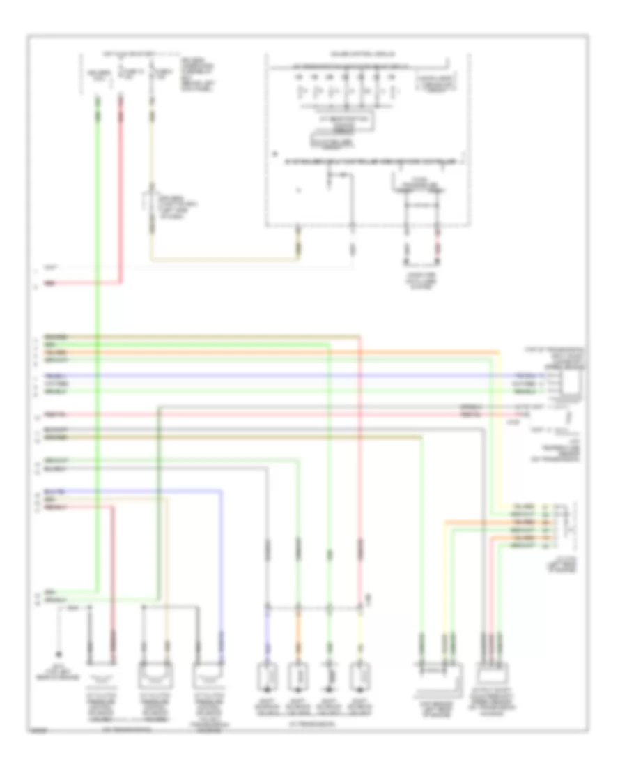 https://portal-diagnostov.com/license.html
Automotive Electricians Portal FZCO
Automotive Electricians Portal FZCO
https://portal-diagnostov.com/license.html
https://portal-diagnostov.com/license.html
Automotive Electricians Portal FZCO
Automotive Electricians Portal FZCOList of elements for 2.4L, Transmission Wiring Diagram (2 of 2) for Honda Crosstour EX 2012:
- (in transmission)
- (left side of dash)
- (on transmission)
- (top of transmission) input shaft (mainshaft) speed sensor
- 10a stabilizer circuit
- 5v stabilizer circuit/controller area network controller
- A/t clutch pressure control solenoid valve a
- A/t clutch pressure control solenoid valve b
- A/t clutch pressure control solenoid valve c (transmission housing)
- A/t gear position dimming circuit
- A/t gear position indicator drive circuit
- Atf temperature sensor (on transmission)
- C105
- Can-h
- Can-l
- Compulsory turning off circuit
- Computer data lines system
- Driver's junction box
- Driver's micu
- Driver's under-dash fuse/relay box (behind left kick panel)
- F-can transceiver
- F15
- F23
- Fuse 10 10a
- Fuse 5 7.5a
- G101 (top left rear of engine)
- Gauge control module
- Hot in on or start
- J/c c103 (left rear of engine)
- Map sensor (left rear of engine)
- Output shaft (countershaft) speed sensor (on transmission housing)
- Red
- Shift solenoid valve a
- Shift solenoid valve b
- Shift solenoid valve c
- Shift solenoid valve d
3.5L
3.5L, Transmission Wiring Diagram (1 of 2) for Honda Crosstour EX 2012
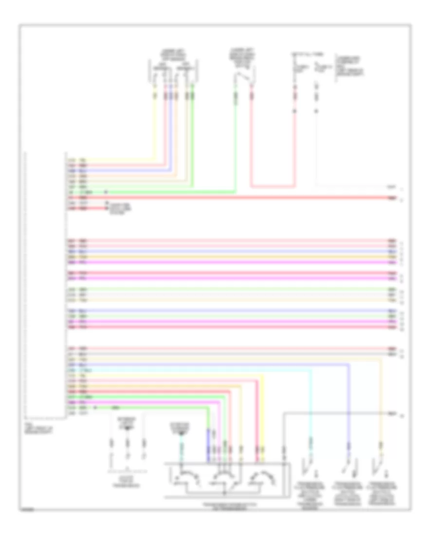 https://portal-diagnostov.com/license.html
Automotive Electricians Portal FZCO
Automotive Electricians Portal FZCO
https://portal-diagnostov.com/license.html
https://portal-diagnostov.com/license.html
Automotive Electricians Portal FZCO
Automotive Electricians Portal FZCOList of elements for 3.5L, Transmission Wiring Diagram (1 of 2) for Honda Crosstour EX 2012:
- (under left side of dash) app sensor
- (under left side of dash) brake pedal position switch
- A16
- A18
- A19
- A24
- A25
- A26
- A27
- A48
- A49
- App sensor 1
- App sensor 2
- B10
- B21
- B34
- B35
- B36
- B37
- B38
- C101
- C12
- C16
- C17
- C18
- C19
- C20
- C21
- C25
- C26
- C27
- C28
- C33
- C35
- C37
- C38
- C39
- C46
- Computer data lines system
- Exterior lights system
- Fuse 15 10a
- Fuse 8 20a
- Hot at all times
- J/c c107 (top of transmission)
- Pcm (left front of engine compt)
- Pnk
- Red
- Starting/ charging system
- Tan
- Transmission fluid pressure switch (4th clutch) (right side of transmission)
- Transmission fluid pressure switch a (2nd clutch) (left side of transmission)
- Transmission fluid pressure switch b (3rd clutch) (under transmission housing)
- Transmission range switch (on transmission)
- Under-hood fuse/relay box (left rear of engine compt)
3.5L, Transmission Wiring Diagram (2 of 2) for Honda Crosstour EX 2012
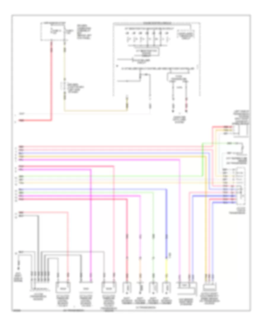 https://portal-diagnostov.com/license.html
Automotive Electricians Portal FZCO
Automotive Electricians Portal FZCO
https://portal-diagnostov.com/license.html
https://portal-diagnostov.com/license.html
Automotive Electricians Portal FZCO
Automotive Electricians Portal FZCOList of elements for 3.5L, Transmission Wiring Diagram (2 of 2) for Honda Crosstour EX 2012:
- (in transmission)
- (left side of dash)
- (left side of transmission housing) input shaft (mainshaft) speed sensor
- (on transmission)
- 10a stabilizer circuit
- 5v stabilizer circuit/controller area network controller
- A/t clutch pressure control solenoid valve a
- A/t clutch pressure control solenoid valve b
- A/t clutch pressure control solenoid valve c (transmission housing)
- A/t gear position dimming circuit
- A/t gear position indicator drive circuit
- Atf temperature sensor (on transmission)
- C102
- Can-h
- Can-l
- Compulsory turning off circuit
- Computer data lines system
- Driver's junction box
- Driver's under-dash fuse/relay box (behind left kick panel)
- F-can transceiver
- F15
- Fuse 10 10a
- Fuse 5 7.5a
- G101 (right side of engine)
- Gauge control module
- Hot in on or start
- J/c c106 (transmission housing)
- J/c c107 (top of transmission)
- Map sensor (right rear of engine)
- Output shaft (countershaft) speed sensor (on transmission housing)
- Pnk
- Red
- Shift solenoid valve a
- Shift solenoid valve b
- Shift solenoid valve c
- Shift solenoid valve d
- Tan
TRUNK, TAILGATE, FUEL DOOR
Tailgate Release Wiring Diagram for Honda Crosstour EX 2012
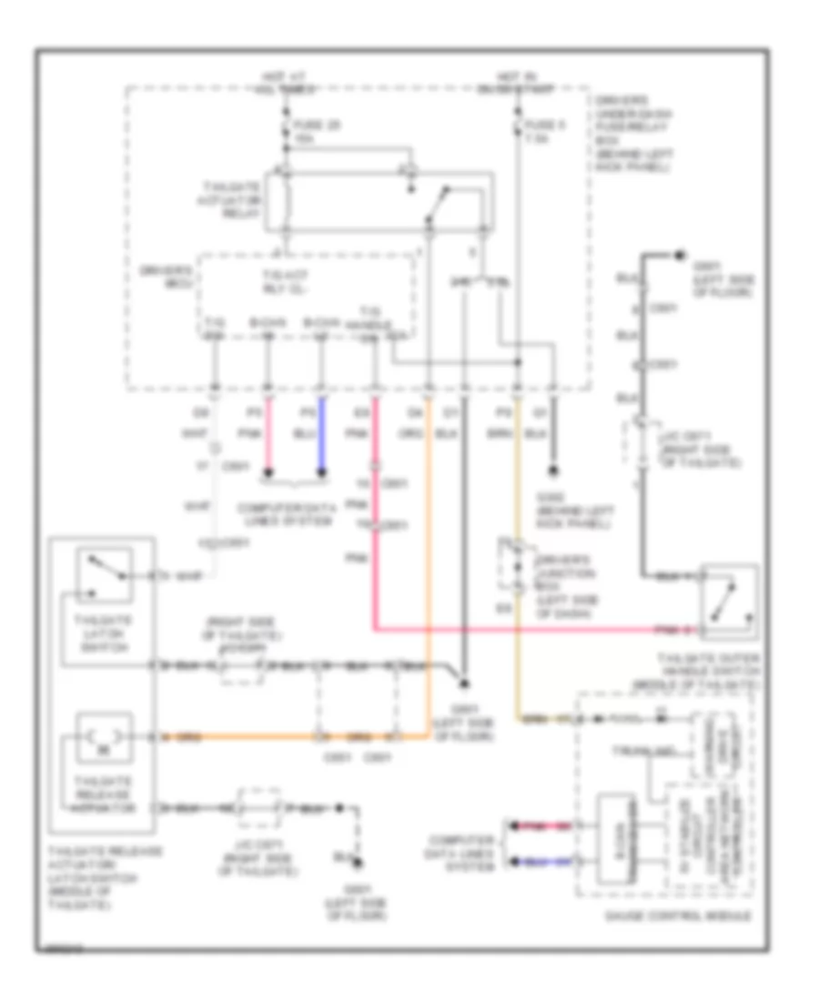 https://portal-diagnostov.com/license.html
Automotive Electricians Portal FZCO
Automotive Electricians Portal FZCO
https://portal-diagnostov.com/license.html
https://portal-diagnostov.com/license.html
Automotive Electricians Portal FZCO
Automotive Electricians Portal FZCOList of elements for Tailgate Release Wiring Diagram for Honda Crosstour EX 2012:
- (right side of tailgate) j/c c671
- 2.4l
- 3.5l
- B-can hi
- B-can lo
- C601
- C651
- Circuit drive warning
- Computer data lines system
- Controller area network controller circuit 5v stabilize
- Driver's junction box (left side of dash)
- Driver's micu
- Driver's under-dash fuse/relay box (behind left kick panel)
- Fuse 25 15a
- Fuse 5 7.5a
- G302 (behind left kick panel)
- G601 (left side of floor)
- Gauge control module
- Hot at all times
- Hot in on or start
- Ig1
- J/c c671 (right side of tailgate)
- Pnk
- T/g act rly cl-
- T/g handle sw
- T/g sw
- Tailgate actuator relay
- Tailgate latch switch
- Tailgate outer handle switch (middle of tailgate)
- Tailgate release actuator
- Tailgate release actuator/ latch switch (middle of tailgate)
- Transceiver b-can
- Trunk ind
WARNING SYSTEMS
Chime Wiring Diagram for Honda Crosstour EX 2012
 https://portal-diagnostov.com/license.html
Automotive Electricians Portal FZCO
Automotive Electricians Portal FZCO
https://portal-diagnostov.com/license.html
https://portal-diagnostov.com/license.html
Automotive Electricians Portal FZCO
Automotive Electricians Portal FZCOList of elements for Chime Wiring Diagram for Honda Crosstour EX 2012:
- "b" pillar)
- (4wd)
- (behind middle of dash) g403
- (left side of floor) (4wd) g801
- (left side of floor) g801
- (right side of floor) (2wd) g802
- (under left side of dash) g401
- 0) off 1) park 2) auto 3) head
- 2.4l
- 3.5l
- 5v stabilizer circuit/ controller area network controller
- A21
- A28
- A34
- A48
- A49
- B can transceiver
- B-can hi
- B-can lo
- Beeper
- Brake system indicator
- C11
- C15
- C22
- C601
- C651
- Combination light switch
- Computer data lines system
- D10
- D15
- Driver's door open indicator
- Driver's door switch (at driver's
- Driver's junction box (left side of dash)
- Driver's micu
- Driver's seat belt buckle switch (in driver's seat belt buckle assembly)
- Driver's under-dash fuse/relay box (behind left kick panel)
- E14
- E15
- F can transceiver
- Fr dr sw l
- Fr dr sw r
- Front passenger's door open indicator
- Front passenger's door switch (at front passenger's "b" pillar)
- Front passenger's seat belt switch (in front passenger's seat belt buckle assembly)
- Fuse 10a
- Fuse 7.5a
- G203 (behind glove box)
- G401 (under left side of dash)
- G402 (under left side of dash)
- G601 (left side of floor)
- Gauge control module
- Gnd (lighting)
- Gnd (micu-p)
- Gnd (micu-s)
- H/l low sw
- H/l off sw
- H24
- H35
- Headlight switch
- Hot at all times
- Hot in on or start
- Ig1 meter
- Ig1 mtr
- Ignition key light
- Ignition key switch
- J/c c671 (right side of tailgate)
- Key interlock solenoid/ ignition key light/ ignition key switch
- Key lt-
- Key sw
- Left rear door indicator
- Left rear door switch (at left "c" pillar)
- Lights on indicator
- Low oil pressure indicator
- Micu p-gnd
- Micu s-gnd
- Oil pressure switch (2.4l) (near oil filter)
- Oil pressure switch (3.5l) (near oil filter)
- Parking brake switch (under center console)
- Passenger's micu
- Passenger's under-dash fuse/relay box (behind right kick panel)
- Pcm (left front of engine compt)
- Pnk
- Q10
- Q13
- Q20
- R10
- R11
- Red
- Right rear door indicator
- Right rear door switch (at right "c" pillar)
- Rr dr sw l
- Rr dr sw r
- Seat belt reminder indicator
- Small sw
- Srs unit (under middle of dash)
- T/g sw
- Tailgate outer handle switch (middle of tailgate)
- Under-hood fuse/relay box (left rear of engine compt)
- Warning control circuit
Tire Pressure Monitoring Wiring Diagram for Honda Crosstour EX 2012
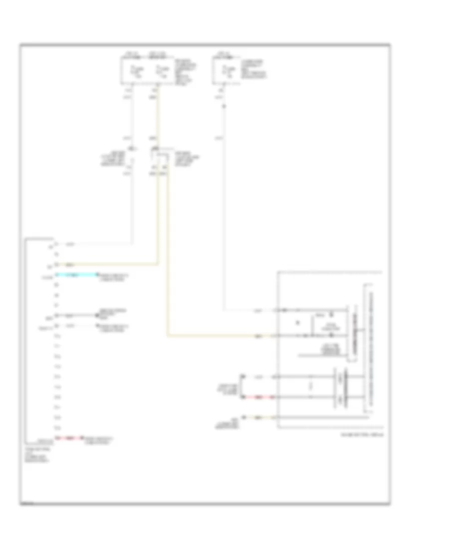 https://portal-diagnostov.com/license.html
Automotive Electricians Portal FZCO
Automotive Electricians Portal FZCO
https://portal-diagnostov.com/license.html
https://portal-diagnostov.com/license.html
Automotive Electricians Portal FZCO
Automotive Electricians Portal FZCOList of elements for Tire Pressure Monitoring Wiring Diagram for Honda Crosstour EX 2012:
- (behind middle of dash) g403
- 5v stabilizer circuit/ controller area network controller
- Can h
- Can l
- Center junction box (under left side of dash)
- Computer data lines system
- Driver's junction box (left side of dash)
- Driver's under-dash fuse/relay box (behind left kick panel)
- F-can hi
- F-can lo
- F-can transceiver
- Fuse 10a
- Fuse 7.5a
- G401 (under left side of dash)
- Gauge control module
- Gnd
- Hot at all times
- Hot in on or start
- Ig1
- K-line
- Low tire pressure indicator
- N13
- Red
- Tpms control unit (under left side of dash)
- Tpms indicator
- Under-hood fuse/relay box (left rear of engine compt)
- Warning drive circuit
WIPER/WASHER
Front Wiper/Washer Wiring Diagram (1 of 2) for Honda Crosstour EX 2012
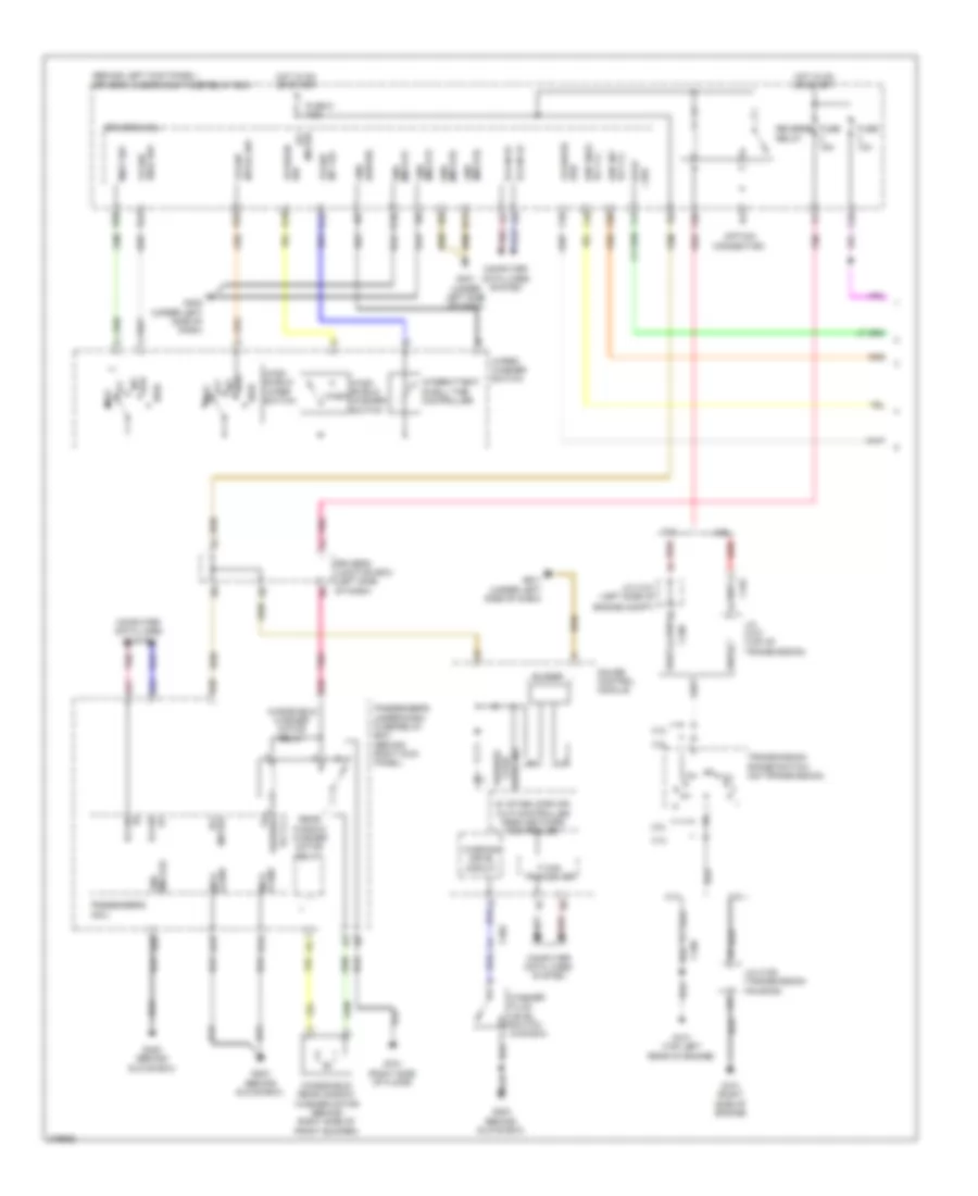 https://portal-diagnostov.com/license.html
Automotive Electricians Portal FZCO
Automotive Electricians Portal FZCO
https://portal-diagnostov.com/license.html
https://portal-diagnostov.com/license.html
Automotive Electricians Portal FZCO
Automotive Electricians Portal FZCOList of elements for Front Wiper/Washer Wiring Diagram (1 of 2) for Honda Crosstour EX 2012:
- (as) fr wiper
- (behind left kick panel) driver's under-dash fuse/relay box
- (micu-p) gnd
- (micu-s) gnd
- (option connector)
- 2.4l
- 3.5l
- 5v stabilizar cir- cuit/controller area network controller
- A21
- A28
- A32
- A34
- B-can hi
- B-can lo
- Buzzer
- C101
- C106
- C202
- Computer data lines system
- Driver's junction box (left side of dash)
- Driver's micu
- Engine compt)
- F can tranceiver
- F14
- F18
- F19
- F20
- F25
- F28
- Fr wip hi/lo sw
- Fuse 10a
- Fuse 15a
- Fuse 5 7.5a
- G101 (right side of engine)
- G101 (top left rear of engine)
- G203 (behind glove box)
- G401 (under left side of dash)
- G402 (under left side of dash)
- G405 (behind glove box)
- G701 (right side of floor)
- Gauge control module
- Gnd (wiper)
- Hi b-can
- High
- Hot in on or start
- Int low
- Int vr+ fr wip
- Int/lo sw fr wip
- Intermittent dwell time controller
- J/c c101 (left side of
- J/c c106 (transmission housing)
- J/c c107 (top of transmission)
- Lo b-can
- Meter ig1
- Mist
- Mist sw
- Off
- P-gnd micu
- Passenger's micu
- Passenger's under-dash fuse/relay box (behind right kick panel)
- Pnk
- Q10
- R11
- R12
- R19
- R20
- R21
- R22
- Rear window washer motor relay
- Red
- Reverse relay
- Rly cl-
- Rly cl- wip hi/lo
- Rly cl- wip int
- S-gnd micu
- Sw fr wash
- Sw stop
- Transmission range switch (on transmission)
- Warning drive circuit
- Wash
- Washer fluid level ind
- Washer fluid level switch (canada)
- Washer fr
- Wind- shield washer switch
- Wind- shield wiper switch
- Windshield washer motor relay
- Windshield/ rear window washer motor (behind right side of front bumper)
- Wiper/ washer switch
Front Wiper/Washer Wiring Diagram (2 of 2) for Honda Crosstour EX 2012
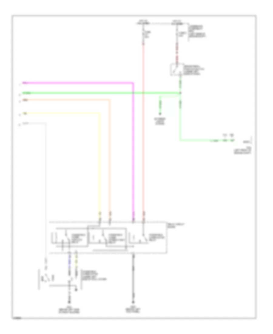 https://portal-diagnostov.com/license.html
Automotive Electricians Portal FZCO
Automotive Electricians Portal FZCO
https://portal-diagnostov.com/license.html
https://portal-diagnostov.com/license.html
Automotive Electricians Portal FZCO
Automotive Electricians Portal FZCOList of elements for Front Wiper/Washer Wiring Diagram (2 of 2) for Honda Crosstour EX 2012:
- 2.4l
- 3.5l
- A42
- Bksw
- Brake pedal position switch (under left side of dash)
- Exterior lights system
- Fuse 3-7 30a
- Fuse 8 20a
- G301 (behind left side of front bumper)
- G302 (behind left kick panel)
- High
- Hot at all times
- Low
- Park
- Pcm (left front of engine compt)
- Red
- Relay circuit board
- Run
- Underhood fuse/relay box (left rear of engine compt)
- Windshield wiper high/low relay
- Windshield wiper intermittent relay
- Windshield wiper motor (under left side of cowl cover)
- Windshield wiper motor relay
Rear Wiper/Washer Wiring Diagram for Honda Crosstour EX 2012
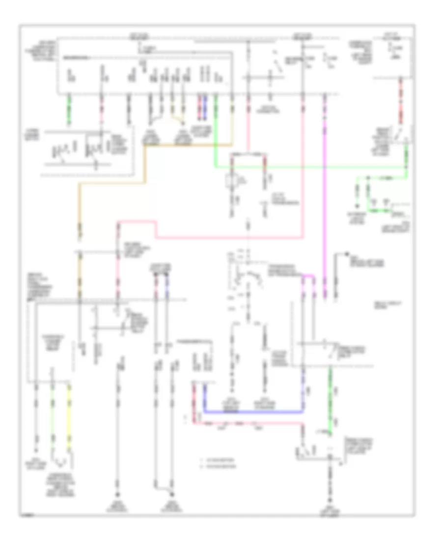 https://portal-diagnostov.com/license.html
Automotive Electricians Portal FZCO
Automotive Electricians Portal FZCO
https://portal-diagnostov.com/license.html
https://portal-diagnostov.com/license.html
Automotive Electricians Portal FZCO
Automotive Electricians Portal FZCOList of elements for Rear Wiper/Washer Wiring Diagram for Honda Crosstour EX 2012:
- (as) rr wiper
- (behind right kick panel) passenger's under-dash fuse/relay box
- (micu-p) gnd
- (micu-s) gnd
- (option connector)
- 2.4l
- 3.5l
- A21
- A26
- A28
- A32
- A34
- A38
- A42
- B-can hi
- B-can lo
- Bksw
- Brake pedal position switch (under left side of dash)
- C101
- C106
- C304
- C306
- C401
- C412
- C601
- Computer data lines system
- D10
- Driver's junction box (left side of dash)
- Driver's micu
- Driver's under-dash fuse/relay box (behind left kick panel)
- E14
- E15
- Exterior lights system
- F14
- F25
- F28
- Fuse 10a
- Fuse 15a
- Fuse 20a
- Fuse 5 7.5a
- G101 (right side of engine)
- G101 (top left rear of engine)
- G203 (behind glove box)
- G301 (behind left side of front bumper)
- G401 (under left side of dash)
- G402 (under left side of dash)
- G405 (behind glove box)
- G601 (left side of floor)
- G701 (right side of floor)
- Gnd (wiper)
- H31
- Hi b-can
- Hot at all times
- Hot in on or start
- J/c 107 (top of transmission)
- J/c c101
- J/c c106 (trans- mission housing)
- Lo b-can
- Meter ig1
- Off
- P-gnd micu
- Park
- Passenger's micu
- Pcm (left front of engine compt)
- Pnk
- Q10
- R11
- R17
- R18
- Rear window washer motor relay
- Rear window wiper motor (left side of tailgate)
- Rear window wiper motor relay
- Rear window wiper/ washer switch
- Red
- Relay circuit board
- Reverse relay
- Rly cl- rr washer
- Rly cl- rr wiper
- Rr wip sw
- Run
- S-gnd micu
- Sw rr wash
- Sw stop
- Transmission range switch (on transmission)
- Under-hood fuse/relay box (left rear of engine compt)
- W/ navigation
- W/o navigation
- Wash
- Windshield washer motor relay
- Wiper/ washer switch
- Wnidshield/ rear window washer motor (behind right side of front bumper)

 Čeština
 Dansk
Dansk Deutsch
 Ελληνικά
 English
 English
 Español
 Suomi
Suomi Français
 Français
 עברית
עברית Hrvatski
 Magyar
 Italiano
 한국어
한국어 Nederlands
 Polski
 Português
 Português
 Română
 Русский
 Slovenčina
 Slovenščina
 Svenska
 Türkçe
 中文 (中国)
