AIR CONDITIONING
Compressor Wiring Diagram for Hummer H3 2010
 https://portal-diagnostov.com/license.html
Automotive Electricians Portal FZCO
Automotive Electricians Portal FZCO
https://portal-diagnostov.com/license.html
https://portal-diagnostov.com/license.html
Automotive Electricians Portal FZCO
Automotive Electricians Portal FZCO
List of elements for Compressor Wiring Diagram for Hummer H3 2010:
- (in hvac harness, approximately 13.5 cm (5.3 in) before breakout to evaporator temperature sensor) j250
- 5v ref
- A/c clutch diode 90
- A/c clutch relay
- A/c compressor clutch (part of a/c compressor)
- A/c on ind
- A/c on switch
- A/c refrigerant pressure sensor (on high pressure hose connection to compressor)
- A/c req sig
- A41
- A42
- A43
- Ac cltch fuse 48 10a
- Body control module (bcm) (behind right front kick panel)
- Computer data lines system
- Engine control module (ecm) (right rear corner of engine compt)
- Evap temp sig
- Evaporator temperature sensor (behind right lower dash)
- G103 (on lower left side of engine block, forward of g102)
- Hot at all times
- Hvac control module (beneath radio)
- Logic
- Low ref
- Manual a/c circuit
- Press sens sig
- Rly ctrl
- Run/ crnk relay
- Serial data
- Underhood fuse block (above left front wheelwell)
- X204
- X205
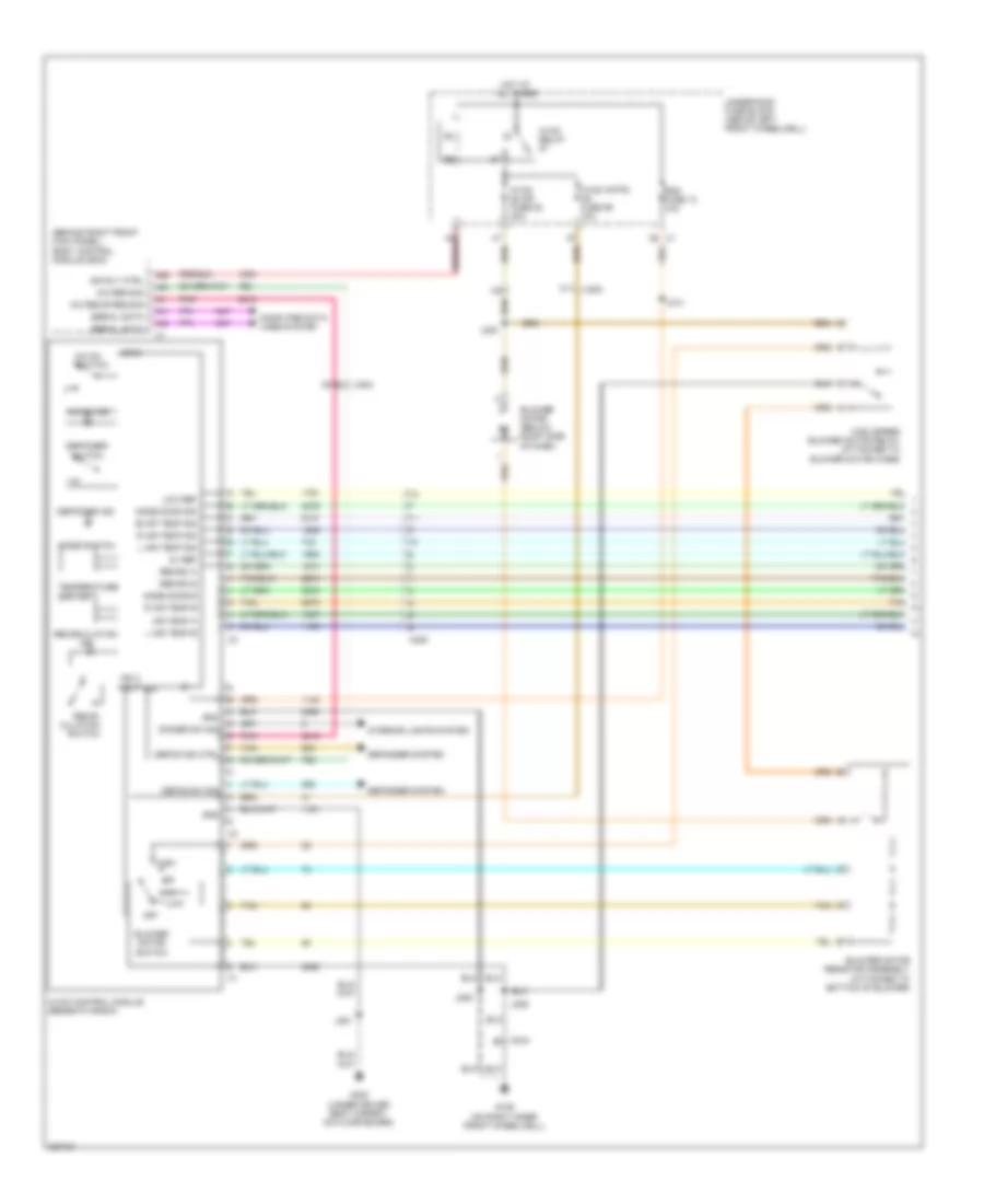
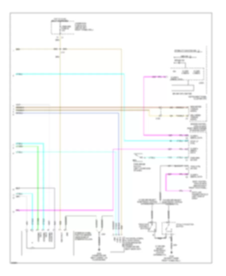
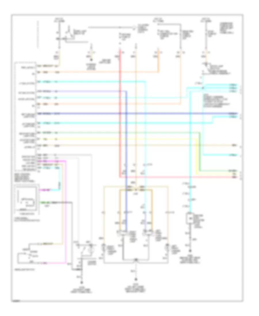
Manual A/C Wiring Diagram (1 of 3) for Hummer H3 2010
 https://portal-diagnostov.com/license.html
Automotive Electricians Portal FZCO
Automotive Electricians Portal FZCO
https://portal-diagnostov.com/license.html
https://portal-diagnostov.com/license.html
Automotive Electricians Portal FZCO
Automotive Electricians Portal FZCOList of elements for Manual A/C Wiring Diagram (1 of 3) for Hummer H3 2010:
- (behind right front kick panel) body control module (bcm)
- 5v ref
- A/c on
- A/c on ind
- A/c recir req sig
- A/c req sig
- A26
- A41
- A42
- A43
- Air temp a
- Blower motor (below right side of dash)
- Blower motor resistor assembly (attached to bottom of blower)
- Blower motor switch
- C11
- Computer data lines system
- Deffoger ind
- Deffoger switch
- Defog ind ctrl
- Defog sw sig
- Defogger system
- Dimmer sw sig
- Evap temp sig
- G106 (on right inner front wheelwell)
- G300 (under driver seat carpet, on floor board)
- Gnd
- High
- High speed blower motor relay (attached to blower motor case)
- Hot at all times
- Hvac blwr fuse 82 30a
- Hvac cntrl hd fuse 59 10a
- Hvac control module (beneath radio)
- Hvac relay
- Ign 3 volt
- Ign rly ctrl
- Interior lights system
- J205
- J206
- J214
- J220
- J251
- L air temp b
- L air temp sig
- Logic
- Low
- Low ref
- Mode door b
- Mode door sig
- Mode switch
- Off
- Pnk
- R air temp b
- R air temp sig
- Rdo fuse 13 10a
- Recir- culation switch
- Recirc a
- Recirc b
- Recirculation ind
- Serial data
- Sig
- Switch
- Tan
- Temperature switch
- Underhood fuse block (above left front wheelwell)
- X200
- X204
- X205
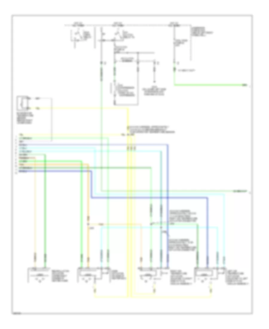
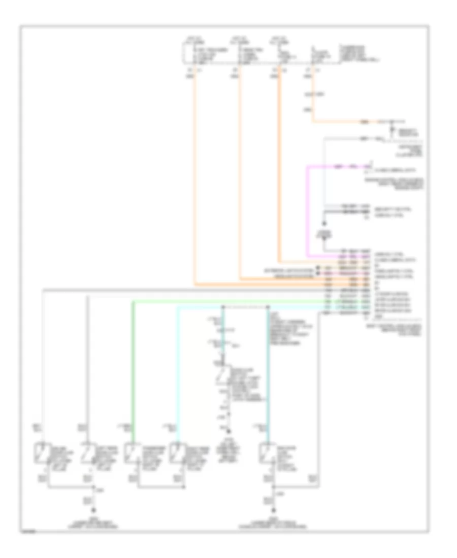
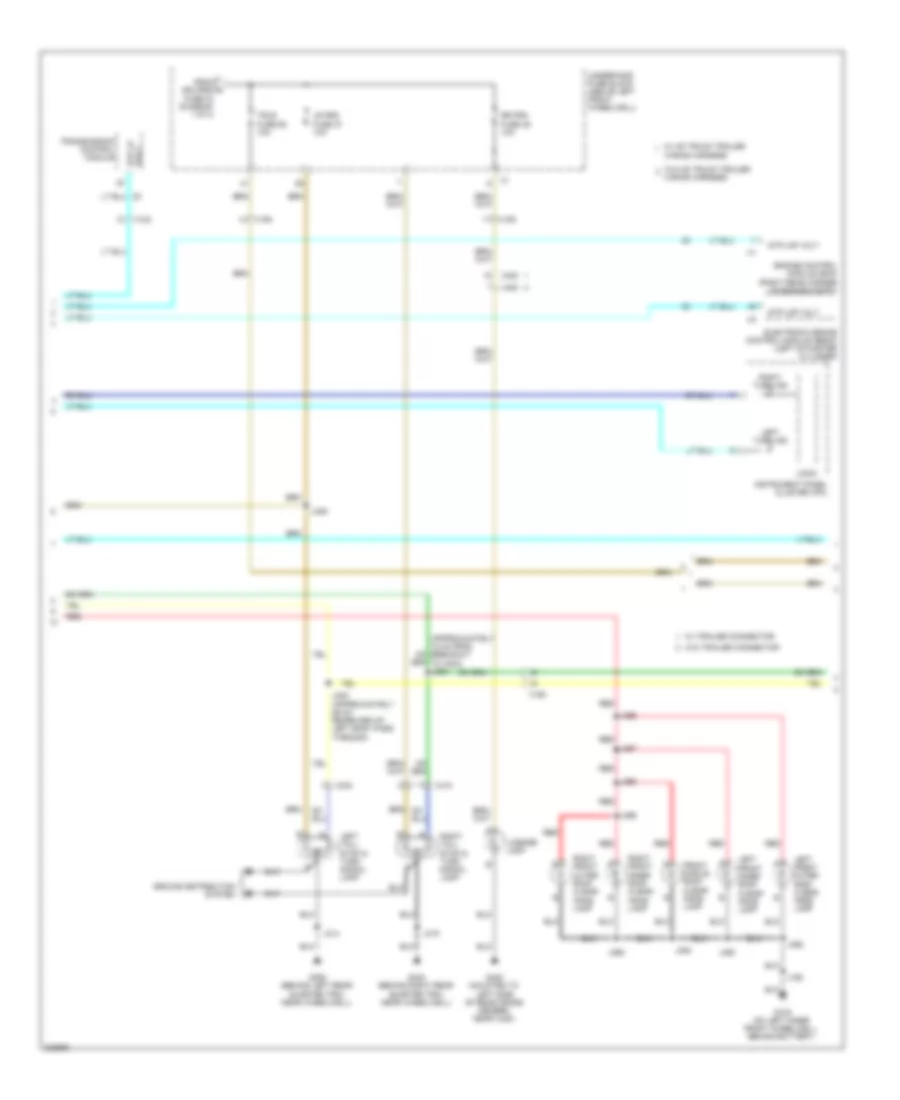
Manual A/C Wiring Diagram (2 of 3) for Hummer H3 2010
 https://portal-diagnostov.com/license.html
Automotive Electricians Portal FZCO
Automotive Electricians Portal FZCO
https://portal-diagnostov.com/license.html
https://portal-diagnostov.com/license.html
Automotive Electricians Portal FZCO
Automotive Electricians Portal FZCOList of elements for Manual A/C Wiring Diagram (2 of 3) for Hummer H3 2010:
- (in hvac harness, approximately 10 cm (3.9 in) back from right air temperature actuator connector)
- (in hvac harness, approximately 28.5 cm (11.2 in) back from right air temperature actuator connector) j240
- 13.5 cm (5.3 in) before breakout to evaporator temperature sensor) j250
- A/c cltch fuse 48 10a
- A/c clutch diode 90
- A/c clutch relay 76
- A/c compressor clutch (part of a/c compressor)
- Cool fans fuse 62 40a
- Evaporator temperature sensor (behind right lower dash)
- G103 (on lower left side of engine block, forward of g102)
- Hot at all times
- J230
- J232
- Left air temperature actuator (mounted to left side of hvac module assembly)
- Logic
- Mode actuator (on side of heater box)
- Recirculation actuator (upper right corner of heater case)
- Right air temperature actuator (mounted to right side of hvac module assembly)
- Run/ crnk relay
- Tan
- Underhood fuse block (above left front wheelwell)
- W/ heavy duty
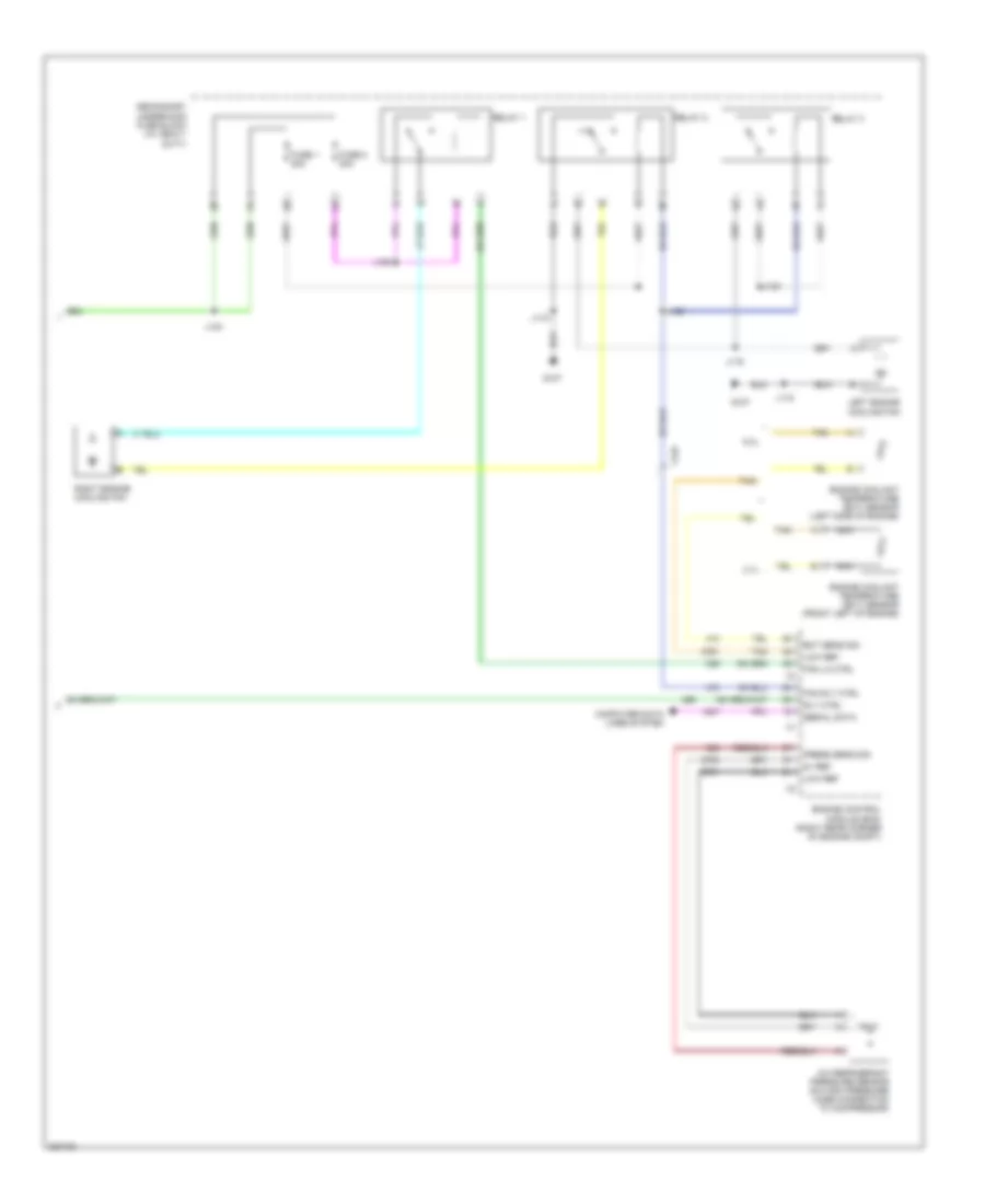
Manual A/C Wiring Diagram (3 of 3) for Hummer H3 2010
 https://portal-diagnostov.com/license.html
Automotive Electricians Portal FZCO
Automotive Electricians Portal FZCO
https://portal-diagnostov.com/license.html
https://portal-diagnostov.com/license.html
Automotive Electricians Portal FZCO
Automotive Electricians Portal FZCOList of elements for Manual A/C Wiring Diagram (3 of 3) for Hummer H3 2010:
- 3.7l
- 5.3l
- 5v ref
- A/c refrigerant pressure sensor (on high pressure hose connection to compressor)
- Computer data lines system
- Ect sens sig
- Engine control module (ecm) (right rear corner of engine compt)
- Engine coolant temperature (ect) sensor (front left of engine)
- Engine coolant temperature (ect) sensor (left side of engine)
- Fan lo ctrl
- Fan rly ctrl
- Fuse 1 20a
- Fuse 2 20a
- G107
- J118
- J119
- J123
- J124
- J125
- J126
- Left engine cooling fan
- Low ref
- Nca
- Press sens sig
- Relay 1
- Relay 2
- Relay 3
- Right engine cooling fan
- Rly ctrl
- Secondary underhood fuse block (w/ heavy duty)
- Serial data
- Tan
- X125
ANTI-LOCK BRAKES
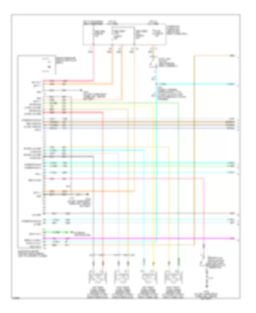
Anti-lock Brakes Wiring Diagram (1 of 2) for Hummer H3 2010
 https://portal-diagnostov.com/license.html
Automotive Electricians Portal FZCO
Automotive Electricians Portal FZCO
https://portal-diagnostov.com/license.html
https://portal-diagnostov.com/license.html
Automotive Electricians Portal FZCO
Automotive Electricians Portal FZCOList of elements for Anti-lock Brakes Wiring Diagram (1 of 2) for Hummer H3 2010:
- 5v ref
- Abs/vses fuse 29 10a
- Abs/vses1 -mtr
- Abs/vses2 -sol fuse 64 30a
- Batt +
- Bkup volt
- Brake fluid level switch (on left side of brake fluid reservoir)
- Brake pressure modulator valve (bpmv)
- Brk fld sig
- Can h
- Can l
- Dlvrd torq sig
- Electronic brake control module (ebcm) (left of master cylinder)
- Exterior lights system
- Fuse 67 40a
- G105 (on left inner front wheelwell, behind battery)
- Gnd
- Hot at all times
- Hot w/ run/crank relay energized
- Ign 3 volt
- Ign volt
- J110
- Left front wheel speed sensor (wss) (attached to left front wheel hub)
- Left rear wheel speed sensor (wss) (attached to left side of rear axle)
- Lf spd low ref
- Lf spd sig
- Low ref
- Lr spd low ref
- Lr spd sig
- Pnk
- Red
- Req torq sig
- Rf spd low ref
- Rf spd sig
- Right front wheel speed sensor (wss) (attached to right front wheel hub)
- Right rear wheel speed sensor (wss) (attached to right side of rear axle)
- Rr spd low ref
- Rr spd sig
- Serial class 2
- Steering pos sig
- Steering sig a
- Steering sig b
- Stop fuse 50 15a
- Stop lamp switch (above brake pedal assembly)
- Stop lp volt
- Tan
- Underhood fuse block (above left front wheelwell)
- X150
Anti-lock Brakes Wiring Diagram (2 of 2) for Hummer H3 2010
 https://portal-diagnostov.com/license.html
Automotive Electricians Portal FZCO
Automotive Electricians Portal FZCO
https://portal-diagnostov.com/license.html
https://portal-diagnostov.com/license.html
Automotive Electricians Portal FZCO
Automotive Electricians Portal FZCOList of elements for Anti-lock Brakes Wiring Diagram (2 of 2) for Hummer H3 2010:
- A17
- A31
- A37
- A38
- A39
- A41
- Abs ind
- Body control module (bcm) (behind right front kick panel)
- Brake ind
- Can h
- Can l
- Class 2 (ebcm)
- Class 2 serial data
- Data link connector (dlc) (left side of dash)
- Delivered torque signal
- Driver info center
- Engine control module (ecm) (right rear corner of engine compt)
- G106 (on right inner front wheelwell)
- G300 (under driver seat carpet, on floor board)
- Gnd
- Hot w/ hvac relay energized
- I/p multi-function switch
- Ign
- Ign 3 volt
- Instrument panel cluster (ipc)
- J141
- J205
- J300
- Logic
- Park brake switch (left lower side of dash)
- Park brk sw sig
- Pulse sig steering
- Requested torque signal
- Sig a steering
- Stability caution ind
- Steering sig b
- Steering wheel position sensor (near base of steering column)
- Stop lp ctrl
- Trac ctrl sw sig
- Traction control switch
- Underhood fuse block (above left front wheelwell)
- Vses/abs fuse 52 10a
- W/ driver select electronic locking differential
- W/o driver select electronic locking differential
- X125
- Yaw rate/lateral & longitudinal accelerometer sensor (under driver seat near x307)
ANTI-THEFT
Forced Entry Wiring Diagram for Hummer H3 2010
 https://portal-diagnostov.com/license.html
Automotive Electricians Portal FZCO
Automotive Electricians Portal FZCO
https://portal-diagnostov.com/license.html
https://portal-diagnostov.com/license.html
Automotive Electricians Portal FZCO
Automotive Electricians Portal FZCOList of elements for Forced Entry Wiring Diagram for Hummer H3 2010:
- A19
- A24
- A25
- A32
- A38
- A39
- A40
- A44
- A47
- Bcm fuse 14 10a
- Body control module (bcm) (behind right front kick panel)
- Class 2 serial data
- Clstr fuse 19 10a
- Driver door ajar switch (in lower left "b" pillar)
- End gate ajar switch (suv) (in right "d" pillar)
- Engine control module (ecm) (right rear corner of engine compt)
- Exterior lights system
- Frt trn/hazrd/ ctsy mir fuse 56 15a
- G105 (on left inner front wheelwell, behind battery)
- G300 (under driver seat carpet, on floor board)
- G320 (under rear of middle console carpet, on floor board)
- Gnd
- Headlamp rly ctrl
- Headlights system
- Hood ajar switch (w/ anti theft cover latch system lock control) (part of hood latch assembly)
- Horn rly ctrl
- Horns system
- Hot at all times
- Instrument panel cluster (ipc)
- J185
- J300
- J320
- J347 (suv) (in body harness, approximately 42 cm rearward of breakout to right seat belt pretensioner)
- Left rear door ajar switch (in lower left "c" pillar)
- Lf door ajar sig
- Lr dr ajar sig sw
- Nca
- Parklamp rly ctrl
- Passenger door ajar switch (in lower right "b" pillar)
- Rear trn/ hazrd fuse 20 20a
- Rf dr ajar sig sw
- Right rear door ajar switch (in lower right "c" pillar)
- Rr dr ajar sw sig
- Security ind ctrl
- Security indicator
- Suv
- Underhood fuse block (above left front wheelwell)
- X115 c3
- X200 b10
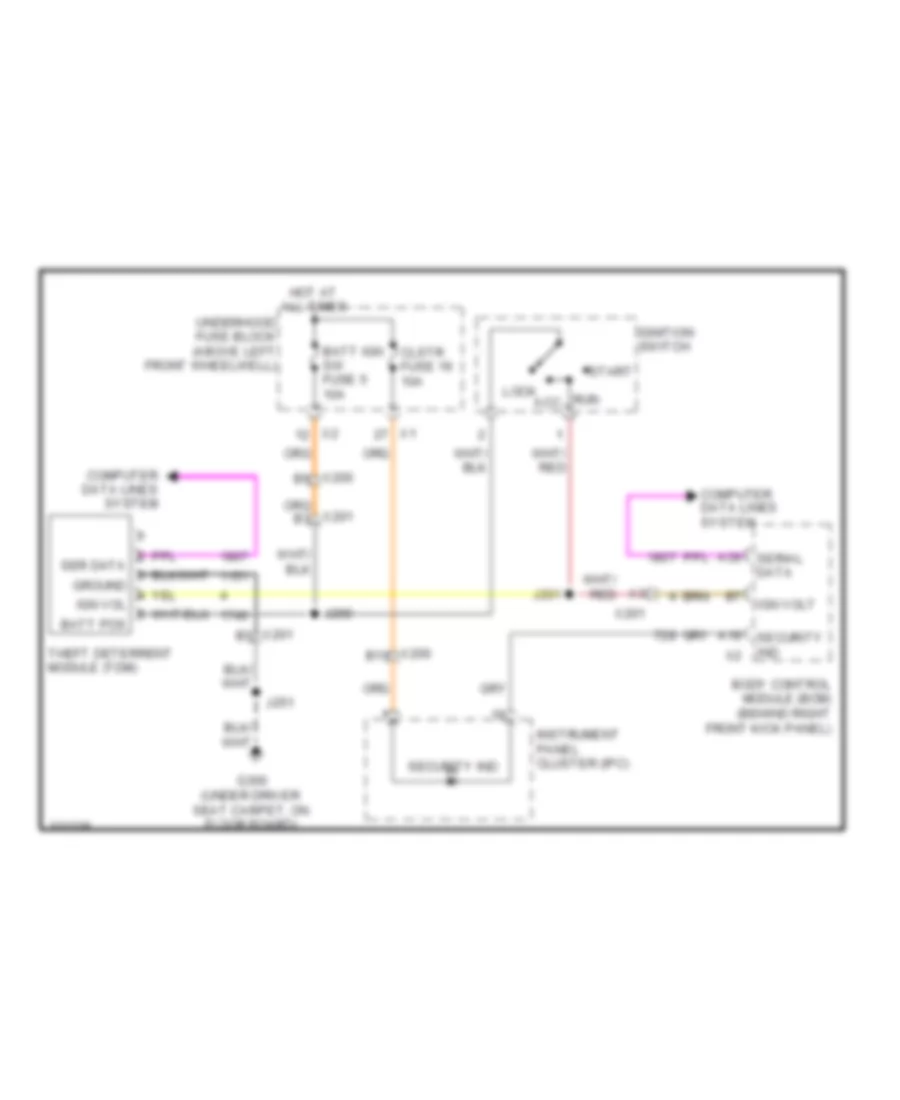
Immobilizer Wiring Diagram for Hummer H3 2010
 https://portal-diagnostov.com/license.html
Automotive Electricians Portal FZCO
Automotive Electricians Portal FZCO
https://portal-diagnostov.com/license.html
https://portal-diagnostov.com/license.html
Automotive Electricians Portal FZCO
Automotive Electricians Portal FZCOList of elements for Immobilizer Wiring Diagram for Hummer H3 2010:
- A19
- A39
- Acc
- B10
- Batt ign sw fuse 5 10a
- Body control module (bcm) (behind right front kick panel)
- Clstr fuse 19 10a
- Computer data lines system
- G300 (under driver seat carpet, on floor board)
- Hot at all times
- Ign volt
- Ignition switch
- Instrument panel cluster (ipc)
- J200
- J201
- J251
- Lock
- Run
- Security ind
- Serial data
- Start
- Theft deterrent module (tdm)
- Underhood fuse block (above left front wheelwell)
- X200
- X201
BODY CONTROL MODULES
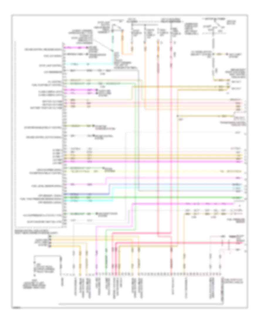
Body Control Modules Wiring Diagram (1 of 2) for Hummer H3 2010
 https://portal-diagnostov.com/license.html
Automotive Electricians Portal FZCO
Automotive Electricians Portal FZCO
https://portal-diagnostov.com/license.html
https://portal-diagnostov.com/license.html
Automotive Electricians Portal FZCO
Automotive Electricians Portal FZCOList of elements for Body Control Modules Wiring Diagram (1 of 2) for Hummer H3 2010:
- (or) cargo lp sw sig
- (under rear of middle console carpet, on floor board) g320
- A/c req sig
- A/c request sig
- A10
- A11
- A12
- A13
- A14
- A15
- A16
- A17
- A18
- A19
- A20
- A21
- A22
- A23
- A24
- A25
- A26
- A27
- A28
- A29
- A30
- A31
- A32
- A33
- A34
- A35
- A36
- A37
- A38
- A39
- A40
- A41
- A42
- A43
- A44
- A45
- A46
- A47
- A48
- Air conditioning system
- Battery +
- Bcm fuse 14 10a
- Body control module (bcm) (behind right front kick panel)
- Class 2 serial data
- Computer data lines system
- Courtesy lamp low ctrl
- Defogger system
- Door locks system
- Door unlock ctrl
- Drl rly ctrl
- Engine controls system
- Exterior lights system
- Fog lamp rly ctrl
- Frt trn/hazrd/ ctsy mir fuse 56 15a
- Ground
- Headlamp rly ctrl
- Headlights system
- Hi beam rly ctrl
- Horn rly ctrl
- Horns system
- Hot at all times
- Ign rly ctrl
- Ign voltage
- Inadvertent pwr ctrl
- Instrument cluster system
- Interior lights system
- J320
- Left trn sig lamp ctrl
- Lf door ajar sw sig
- Lr door ajar sw sig
- Lr park lamps ctrl
- Lr stop/turn lamp ctrl
- Mirrors system
- Park brake sw sig
- Park lamp rly ctrl
- Pass dr lock sw lock ctrl
- Pnk
- Power distribution system
- Rap rly coil ctrl
- Rear defog rly ctrl
- Rear trn/ hazrd fuse 20 20a
- Red
- Rf door ajar sw sig
- Right trn sig lamp ctrl
- Rr door ajar sw sig
- Rr stop/turn lamp ctrl
- Starting/charging system
- Stop lamp ctrl
- Underhood fuse block (above left front wheelwell)
- Windshield washer pmp ctrl
- Wiper mtr prk sw sig
- Wiper sw sig 2
- Wiper/washer system
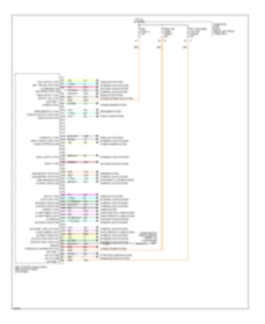
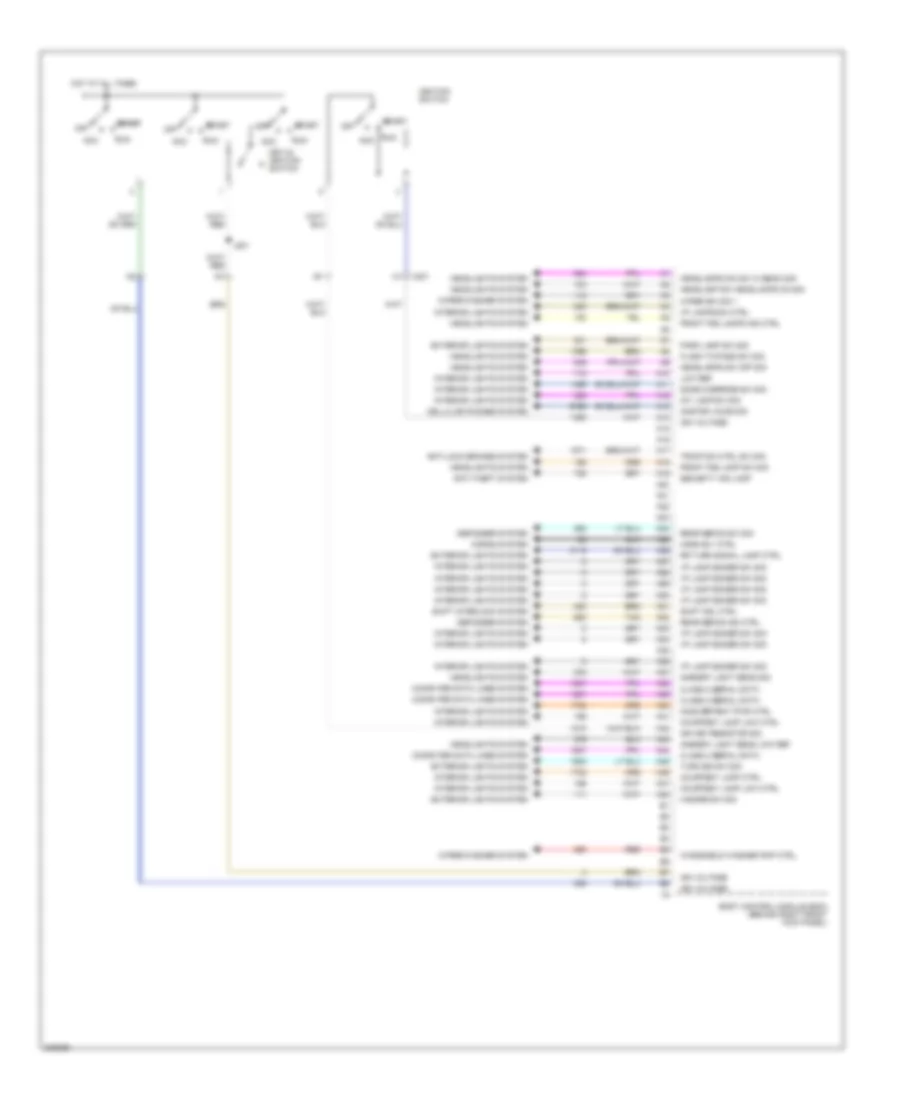
Body Control Modules Wiring Diagram (2 of 2) for Hummer H3 2010
 https://portal-diagnostov.com/license.html
Automotive Electricians Portal FZCO
Automotive Electricians Portal FZCO
https://portal-diagnostov.com/license.html
https://portal-diagnostov.com/license.html
Automotive Electricians Portal FZCO
Automotive Electricians Portal FZCOList of elements for Body Control Modules Wiring Diagram (2 of 2) for Hummer H3 2010:
- A10
- A11
- A12
- A13
- A14
- A15
- A16
- A17
- A18
- A19
- A20
- A21
- A22
- A23
- A24
- A25
- A26
- A27
- A28
- A29
- A30
- A31
- A32
- A33
- A34
- A35
- A36
- A37
- A38
- A39
- A40
- A41
- A42
- A43
- A44
- A45
- A46
- A47
- A48
- Acc
- Ambient light sens low ref
- Ambient light sens sig
- Anti-lock brakes system
- Anti-theft system
- Body control module (bcm) (behind right front kick panel)
- Cellular phones system
- Class 2 serial data
- Computer data lines system
- Courtesy lamp ctrl
- Courtesy lamp low ctrl
- Defogger system
- Dome override sw sig
- Exterior lights system
- Flash to pass sw sig
- Front fog lamp sw sig
- Front fog lamps ind ctrl
- Hazard sw sig
- Headlamp sw headlamps on sig
- Headlamps dim sw hi beam sig
- Headlamps sw off sig
- Headlights system
- Horn rly ctrl
- Horns system
- Hot at all times
- I/p lamp dimmer sw sig
- I/p lamps dim ctrl
- Ign key resistor sig
- Ign voltage
- Ignition switch
- Inadvertent pwr ctrl
- Int lamp sw sig
- Interior lights system
- J201
- Key-in ignition switch
- Low ref
- Off
- Onstar voice sig
- Park lamp sw sig
- Rear defog ind ctrl
- Rear defog sw sig
- Red
- Rr turn signal lamp ctrl
- Run
- Security ind lamp
- Shift interlock system
- Shift sol ctrl
- Start
- Tan
- Traction ctrl sw sig
- Turn sig sw sig
- Windshield washer pmp ctrl
- Wiper sw sig 1
- Wiper/washer system
- X201
COMPUTER DATA LINES
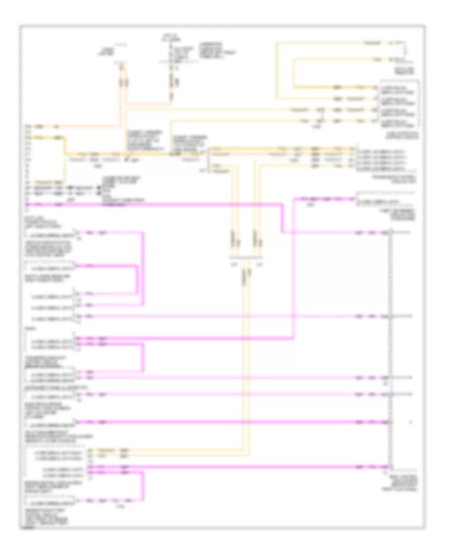
Computer Data Lines Wiring Diagram for Hummer H3 2010
 https://portal-diagnostov.com/license.html
Automotive Electricians Portal FZCO
Automotive Electricians Portal FZCO
https://portal-diagnostov.com/license.html
https://portal-diagnostov.com/license.html
Automotive Electricians Portal FZCO
Automotive Electricians Portal FZCOList of elements for Computer Data Lines Wiring Diagram for Hummer H3 2010:
- (in body harness, approximately 1 cm to right of park brake) j296
- (in body harness, approximately 31 cm to left of park brake switch breakout)
- (under driver seat carpet, on floor board) g300
- A/t
- A38
- A39
- A41
- A42
- A44
- A47
- Aux dwr1/ cig ltr fuse 51 20a
- Body control module (bcm) (behind right front kick panel)
- Cigar lighter
- Class 2 serial data
- Data link connector (dlc) (left side of dash)
- Data link resistor
- Digital radio receiver (right side of dash)
- Electronic brake control module (ebcm) (left of master cylinder)
- Engine control module (ecm) (right rear corner of engine compt)
- Fuel pump flow control module
- G106 (on right inner front wheelwell)
- Generator battery control module (left front of engine compt, near battery)
- Hi spd gmlan serial data bus+
- Hi spd gmlan serial data bus-
- Hi spd lan serial data +
- Hi spd lan serial data -
- Hi spd serial data bus +
- Hi spd serial data bus -
- Hot at all times
- Inflatable restraint sensing & diagnostic module (sdm) (beneath lower console)
- Instrument panel cluster (ipc)
- J205
- J251
- J297
- M/t
- Radio
- Tan
- Theft deterrent module (tdm) (if equipped)
- Transfer case shift control module (behind glove box)
- Transmission control module (tcm)
- Underhood fuse block (above left front wheelwell)
- Vehicle communication interface module (vcim) (center of dash below hvac control head)
- X102
- X150
- X200
- X201
COOLING FAN
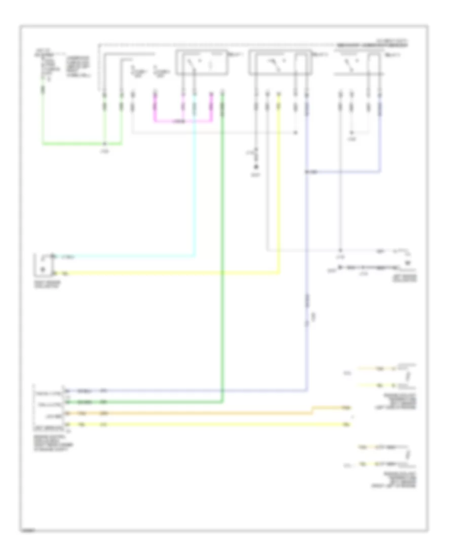
Cooling Fan Wiring Diagram for Hummer H3 2010
 https://portal-diagnostov.com/license.html
Automotive Electricians Portal FZCO
Automotive Electricians Portal FZCO
https://portal-diagnostov.com/license.html
https://portal-diagnostov.com/license.html
Automotive Electricians Portal FZCO
Automotive Electricians Portal FZCOList of elements for Cooling Fan Wiring Diagram for Hummer H3 2010:
- (w/ heavy duty) secondary underhood fuse block
- 3.7l
- 5.3l
- Cool fans fuse 62 40a
- Ect sens sig
- Engine control module (ecm) (right rear corner of engine compt)
- Engine coolant temperature (ect) sensor (front left of engine)
- Engine coolant temperature (ect) sensor (left side of engine)
- Fan lo ctrl
- Fan rly ctrl
- Fuse 1 20a
- Fuse 2 20a
- G107
- Hot at all times
- J118
- J119
- J123
- J124
- J125
- J126
- Left engine cooling fan
- Low ref
- Nca
- Relay 1
- Relay 2
- Relay 3
- Right engine cooling fan
- Tan
- Underhood fuse block (above left front wheelwell)
- X125
CRUISE CONTROL
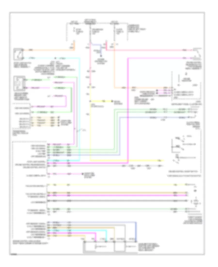
Cruise Control Wiring Diagram for Hummer H3 2010
 https://portal-diagnostov.com/license.html
Automotive Electricians Portal FZCO
Automotive Electricians Portal FZCO
https://portal-diagnostov.com/license.html
https://portal-diagnostov.com/license.html
Automotive Electricians Portal FZCO
Automotive Electricians Portal FZCOList of elements for Cruise Control Wiring Diagram for Hummer H3 2010:
- (suv) (in body harness, approximately 14 cm to right of stop lamp switch breakout in main harness)
- 3.7l
- 5 volt reference 2
- 5-volt ref
- 5-volt reference 1
- 5-volt reference 2
- A/t
- Accelerator pedal position (app) sensor (on accelerator pedal bracket)
- App sensor 1 signal
- App sensor 2 signal
- B10
- Class 2 serial data
- Clstr fuse 19 10a
- Clutch pedal position (cpp) sensor (3.7l)
- Computer data lines system
- Cpp sensor sig
- Cruise control on/off switch
- Cruise control release signal
- Cruise control release switch (top of brake pedal assembly)
- Cruise control switch
- Cruise indicator
- Cruise/misc fuse 35 10a
- Engine control module (ecm) (right rear corner of engine compt)
- G300 (under driver seat carpet, on floor board)
- Gmlan hi (+)
- Gmlan hi (-)
- Gnd
- Hot at all times
- Hot w/ run/ crank relay energized
- Instrument panel cluster (ipc)
- J215 j217 (truck) (body harness, 7 cm left of accelerator pedal)
- J251
- J272 (w/ spo dvd 2)
- Logic
- Low ref
- Low reference
- M/t
- Off
- On/
- Pnk
- Power distribution system
- Res+
- Set-
- Sound systems
- Stop fuse 50 15a
- Stop lamp control
- Stop lamp switch (above brake pedal assembly)
- Tac motor control-1
- Tac motor control-2
- Tan
- Throttle body (top of engine, mounted on upper air intake manifold)
- Tp sensor 1 signal
- Tp sensor 2 signal
- Transmission control module (tcm)
- Turn signal/multi-function switch
- Underhood fuse block (above left front wheelwell)
- Vehicle speed sensor (vss) (left rear of transfer case)
- Vss high signal
- Vss low signal
- X125
- X200
- X201
DEFOGGERS
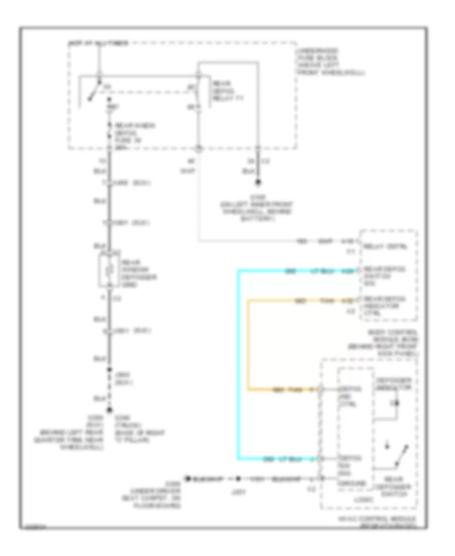
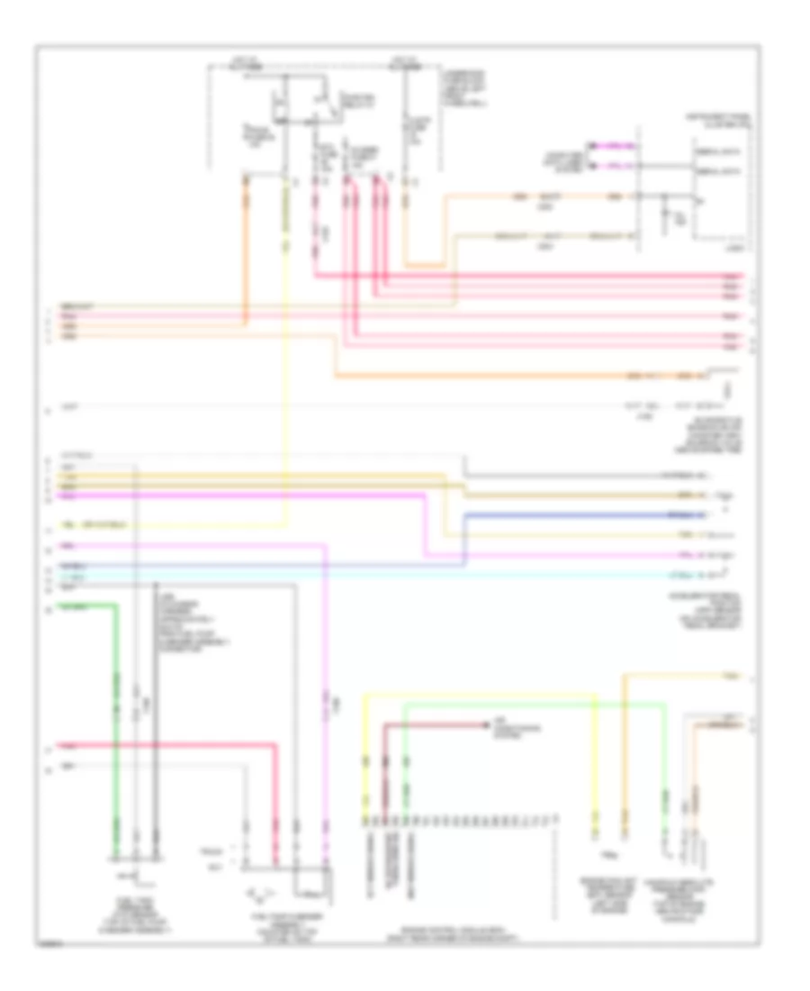
Defoggers Wiring Diagram for Hummer H3 2010
 https://portal-diagnostov.com/license.html
Automotive Electricians Portal FZCO
Automotive Electricians Portal FZCO
https://portal-diagnostov.com/license.html
https://portal-diagnostov.com/license.html
Automotive Electricians Portal FZCO
Automotive Electricians Portal FZCOList of elements for Defoggers Wiring Diagram for Hummer H3 2010:
- (suv)
- A x2
- A10
- A24
- A32
- Body control module (bcm) (behind right front kick panel)
- Defog ind ctrl
- Defog sw sig
- Defogger indicator
- G105 (on left inner front wheelwell, behind battery)
- G300 (under driver seat carpet, on floor board)
- G340 (truck) (base of right "c" pillar)
- G350 (suv) (behind left rear quarter trim, near wheelwell)
- Ground
- Hot at all times
- Hvac control module (beneath radio)
- J251
- J900
- Logic
- Rear defog indicator ctrl
- Rear defog relay 71
- Rear defog switch sig
- Rear defogger switch
- Rear window defogger grid
- Rear wndw defog fuse 30 20a
- Relay cntrl
- Tan
- Underhood fuse block (above left front wheelwell)
- X450
- X901
ENGINE PERFORMANCE
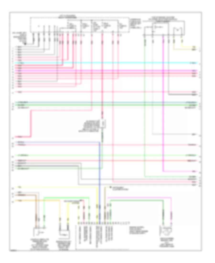
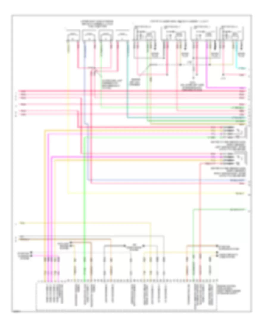
3.7L VIN E
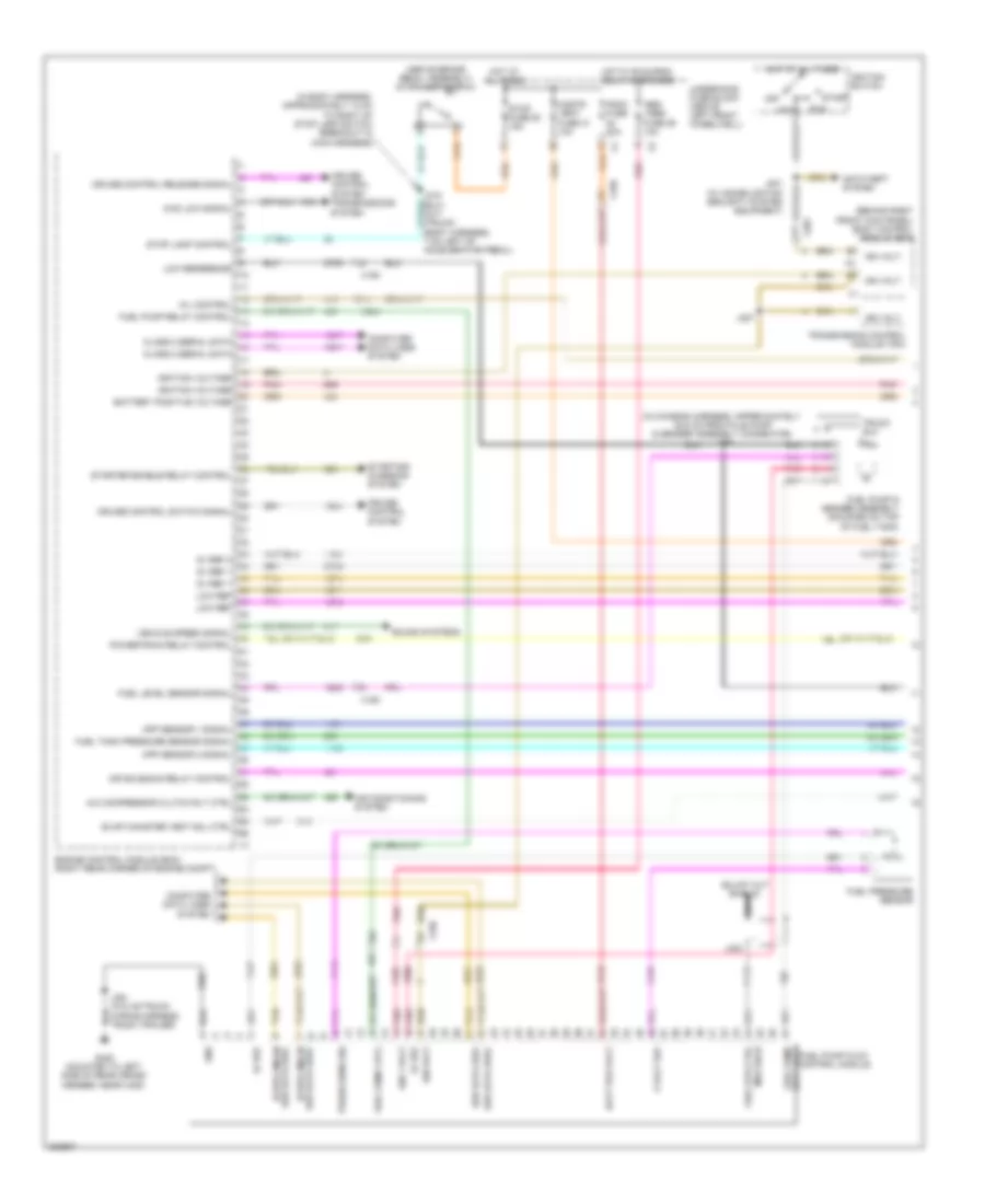
3.7L VIN E, Engine Performance Wiring Diagram (1 of 5) for Hummer H3 2010
 https://portal-diagnostov.com/license.html
Automotive Electricians Portal FZCO
Automotive Electricians Portal FZCO
https://portal-diagnostov.com/license.html
https://portal-diagnostov.com/license.html
Automotive Electricians Portal FZCO
Automotive Electricians Portal FZCOList of elements for 3.7L VIN E, Engine Performance Wiring Diagram (1 of 5) for Hummer H3 2010:
- (above brake pedal assembly) stop lamp switch
- (behind right front kick panel) body control module (bcm)
- (in body harness, approximately 14 cm to right of stop lamp switch breakout in main harness)
- (in chassis harness, approximately 22.5 cm from fule pump & sender assembly connector) j359
- 4wd low signal
- 5 volt ref
- 5v ref 1
- 5v ref 2
- A/c compressor clutch rly ctrl
- Abs/ vses fuse 29 10a
- Acc
- Air conditioning system
- Air solenoid relay control
- Anti-theft system
- App sensor 1 signal
- App sensor 2 signal
- Batt pos volt
- Battery positive voltage
- Class 2 serial data
- Cnstr vent fuse 31 10a
- Computer data lines system
- Cruise control release signal
- Cruise control switch signal
- Cruise control system
- Engine control module (ecm) (right rear corner of engine compt)
- Evap canister vent sol ctrl
- Fscm fuse 20a
- Fuel level sensor signal
- Fuel pressure sensor
- Fuel pump
- Fuel pump & sender assembly (mounted on top of fuel tank)
- Fuel pump crtl
- Fuel pump flow control module
- Fuel pump relay control
- Fuel sys ctrl
- Fuel tank pressure sensor signal
- G420 (mounted to left side of rear cross member, near x420)
- Gnd
- Hi spd gmlan
- Hot at all times
- Hot w/ run/crnk relay energized
- Ign 1 volt
- Ign volt
- Ignition switch
- Ignition voltage
- J201 (w/ immobilization security system equipment)
- J207
- J215 (suv) j217 (truck) (body harness, 7 cm left of accelerator pedal)
- J423
- Lo ref
- Low ref
- Low reference
- Mil control
- Mod shld
- Nca
- Off
- Pnk
- Powertrain relay control
- Press sens sig
- Run
- Ser data bus+
- Ser data bus-
- Sound systems
- Sply volt
- Start
- Starter enable relay control
- Starting/ charging system
- Stop fuse 50 15a
- Stop lamp control
- Tan
- Transmission control module (tcm)
- Transmissions system
- Truck suv
- Underhood fuse block (above left front wheelwell)
- Vehicle speed signal
- X150
- X201
- X204
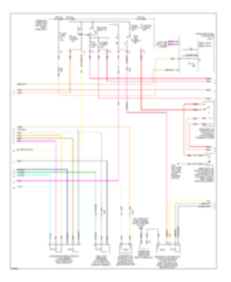
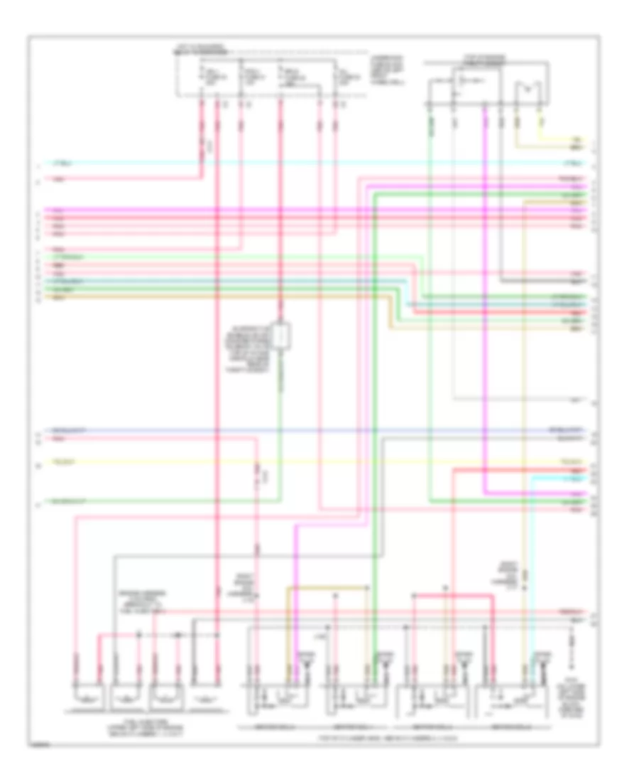
3.7L VIN E, Engine Performance Wiring Diagram (2 of 5) for Hummer H3 2010
 https://portal-diagnostov.com/license.html
Automotive Electricians Portal FZCO
Automotive Electricians Portal FZCO
https://portal-diagnostov.com/license.html
https://portal-diagnostov.com/license.html
Automotive Electricians Portal FZCO
Automotive Electricians Portal FZCOList of elements for 3.7L VIN E, Engine Performance Wiring Diagram (2 of 5) for Hummer H3 2010:
- (on lower left side of engine block, forward of g102) g103
- Accelerator pedal position (app) sensor (on accelerator pedal bracket)
- Air pump fuse 62 60a
- Air sol fuse 44 15a
- Air sol relay
- B10
- Clstr fuse 10a
- Computer data lines system
- Etc fuse 15a
- Evaporative emission (evap) canister vent solenoid valve (above spare tire)
- Fuel tank pressure (ftp) sensor (top of fuel pump & sender assembly)
- G103 (on lower left side of engine block, forward of g102)
- Hot at all times
- Instrument panel cluster (ipc)
- Logic
- Mil ind
- Nca
- O2 snsr fuse 47 15a
- Pcm-b fuse 25 10a
- Pnk
- Pwr/trn relay 81
- Red
- Secondary air injection (air) pump (w/ electric air injection reactor) (mounted to right front side of radiator support)
- Secondary air injection (air) pump relay (top of engine, at rear of intake)
- Secondary air injection (air) pump solenoid (w/ electric air injection reactor) (right side of engine, above exhaust)
- Serial data
- Tan
- Underhood fuse block (above left front wheelwell)
- Up shift ind
- X125
- X150
- X200
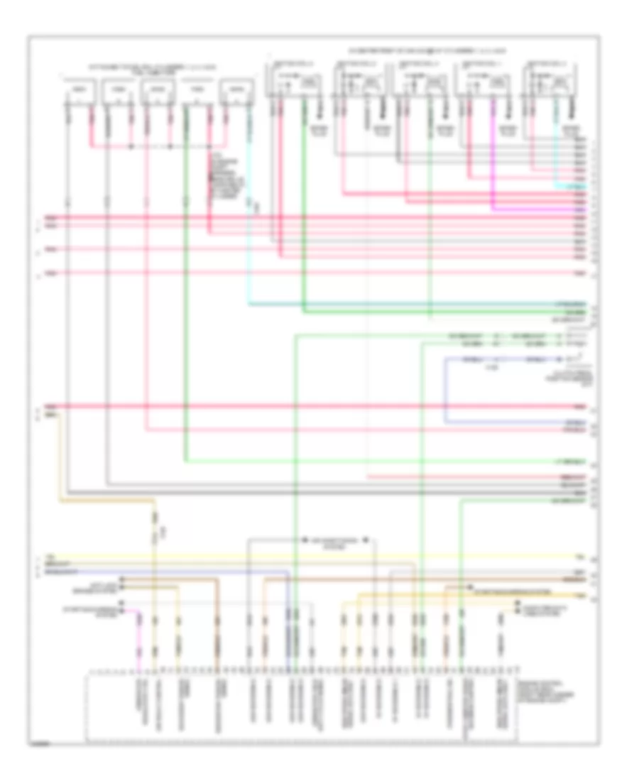
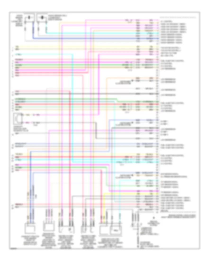
3.7L VIN E, Engine Performance Wiring Diagram (3 of 5) for Hummer H3 2010
 https://portal-diagnostov.com/license.html
Automotive Electricians Portal FZCO
Automotive Electricians Portal FZCO
https://portal-diagnostov.com/license.html
https://portal-diagnostov.com/license.html
Automotive Electricians Portal FZCO
Automotive Electricians Portal FZCOList of elements for 3.7L VIN E, Engine Performance Wiring Diagram (3 of 5) for Hummer H3 2010:
- (attached to fuel rail cylinders 1, 2, 3, 4 & 5) fuel injectors
- (in center front of cam cover at cylinders 1, 2, 3, 4 & 5)
- 5v reference
- 5v reference 1
- A pnk
- Air conditioning system
- Air relay control
- Anti-lock brakes system
- Clutch pedal position sensor (m/t)
- Computer data lines system
- Delivered torque
- Duty cycle signal generator field
- Engine control module (ecm) (right rear corner of engine compt)
- Evap canister purge
- Generator
- High speed gmlan
- Ignition coil 1
- Ignition coil 2
- Ignition coil 3
- Ignition coil 4
- Ignition coil 5
- J103 (in engine compt harness, pnk near grille lamps relay, by master cylinder)
- Low reference
- Nca
- Park/neutral sig
- Pnk
- Regulator ctrl
- Requested torque signal
- Serial data bus +
- Serial data bus -
- Signal
- Solenoid control
- Spark plug
- Starting/charging system
- Tan
- X101
- X125
3.7L VIN E, Engine Performance Wiring Diagram (4 of 5) for Hummer H3 2010
 https://portal-diagnostov.com/license.html
Automotive Electricians Portal FZCO
Automotive Electricians Portal FZCO
https://portal-diagnostov.com/license.html
https://portal-diagnostov.com/license.html
Automotive Electricians Portal FZCO
Automotive Electricians Portal FZCOList of elements for 3.7L VIN E, Engine Performance Wiring Diagram (4 of 5) for Hummer H3 2010:
- (on lower left side of engine block, forward of g102) g103
- (top of engine, mounted on upper air intake manifold) throttle body
- A/c refrigerant
- Air conditioning system
- Air injection reaction ctrl valve ctrl
- Air pump rly/tcm fuse 17 10a
- Cpp sensor signal
- Ect sensor signal
- Engine control module (ecm) (right rear corner of engine compt)
- Engine coolant temperature (ect) sensor (front left of engine)
- Erls fuse 22 15a
- Evaporative emission (evap) canister purge solenoid valve (below intake, in back of alternator)
- Hot w/ run/crnk relay 78 energized
- Ign 1 fuse 33 15a
- Inj fuse 23 15a
- Instrument cluster system
- Manifold absolute pressure (map) sensor (at top right side rear of engine, on intake manifold)
- Map sensor signal
- Nca
- Oil press sw sig
- Pcm-1 fuse 21 10a
- Pnk
- Press sens sig
- Tan
- Underhood fuse block (above left front wheelwell)
- Vehicle speed sensor (vss) (m/t) (left rear of transfer case)
- Vss high signal
- Vss low signal
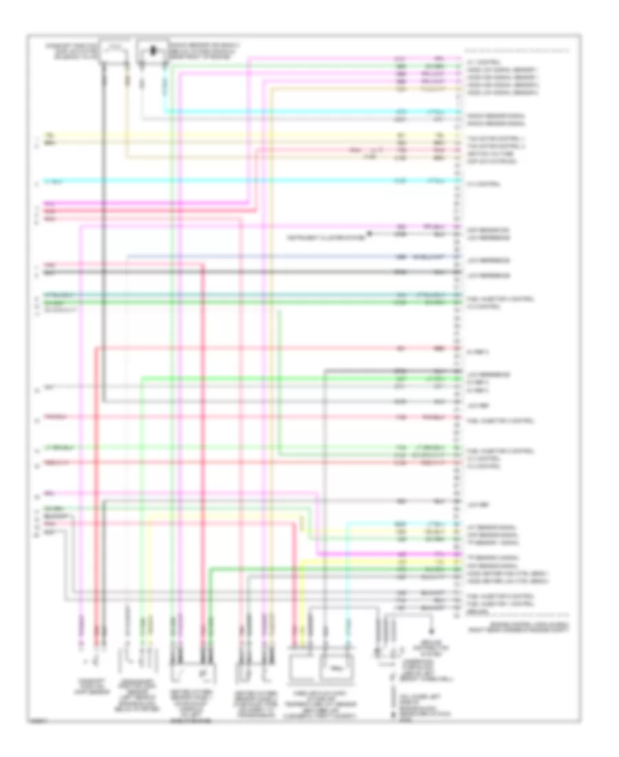
3.7L VIN E, Engine Performance Wiring Diagram (5 of 5) for Hummer H3 2010
 https://portal-diagnostov.com/license.html
Automotive Electricians Portal FZCO
Automotive Electricians Portal FZCO
https://portal-diagnostov.com/license.html
https://portal-diagnostov.com/license.html
Automotive Electricians Portal FZCO
Automotive Electricians Portal FZCOList of elements for 3.7L VIN E, Engine Performance Wiring Diagram (5 of 5) for Hummer H3 2010:
- (on lower left side of engine block, rearward of g103) g102
- 5v ref 2
- Camshaft position (cmp) actuator solenoid valve
- Camshaft position (cmp) sensor
- Ckp sensor signal
- Cmp actuator sol
- Cmp sensor sig
- Crankshaft position (ckp) sensor (left rear of engine block, below starter)
- Engine control module (ecm) (right rear corner of engine compt)
- Fuel injector 1 control
- Fuel injector 2 control
- Fuel injector 3 control
- Fuel injector 4 control
- Fuel injector 5 control
- Ground
- Ground distribution system
- Heated oxygen sensor (ho2s) 1 (on exhaust manifold on left side of engine)
- Heated oxygen sensor (ho2s) 2 (in exhaust pipe, adjacent to transmission)
- Ho2s heater high ctrl sens 1
- Ho2s heater low ctrl sens 2
- Ho2s high signal sensor 1
- Ho2s high signal sensor 2
- Ho2s low signal sensor 1
- Ho2s low signal sensor 2
- Iat sensor signal
- Ic 1 control
- Ic 2 control
- Ic 3 control
- Ic 4 control
- Ic 5 control
- Ignition voltage
- Instrument cluster system
- Knock sensor (ks) bank 2 (below intake manifold, near front of engine)
- Knock sensor signal
- Low ref
- Low reference
- Maf sensor signal
- Mass air flow (maf)/ intake air temperature (iat) sensor (between air cleaner & throttle body)
- Nca
- Pnk
- Red
- Tac motor control 1
- Tac motor control 2
- Tp sensor 1 signal
- Tp sensor 2 signal
- X125
- X3 underhood fuse block (above left x3 front wheelwell)
5.3L VIN P
5.3L VIN P, Engine Performance Wiring Diagram (1 of 5) for Hummer H3 2010
 https://portal-diagnostov.com/license.html
Automotive Electricians Portal FZCO
Automotive Electricians Portal FZCO
https://portal-diagnostov.com/license.html
https://portal-diagnostov.com/license.html
Automotive Electricians Portal FZCO
Automotive Electricians Portal FZCOList of elements for 5.3L VIN P, Engine Performance Wiring Diagram (1 of 5) for Hummer H3 2010:
- (behind right front kick panel) body control module (bcm)
- (in body harness, approximately 14 cm to right of stop lamp switch breakout in main harness)
- 4wd low signal
- 5 volt reference
- 5v ref 1
- 5v ref 2
- A/c compressor clutch rly ctrl
- Abs/ vses fuse 29 10a
- Acc
- Air conditioning system
- Anti-theft system
- App sensor 1 signal
- App sensor 2 signal
- Batt pos volt
- Battery positive voltage
- Class 2 serial data
- Cnstr vent fuse 31 10a
- Computer data lines system
- Cruise control release signal
- Cruise control switch signal
- Cruise control system
- Engine control module (ecm) (right rear corner of engine compt)
- Evap canister vent sol ctrl
- Fscm fuse 54 20a
- Fuel level sensor signal
- Fuel pressure sensor
- Fuel pump flow control module
- Fuel pump relay control
- Fuel pump sply volt
- Fuel tank pressure sensor signal
- G420 (mounted to left side of rear cross member, near x420)
- Ground
- Hot at all times
- Hot w/ run/crnk relay energized
- Ign volt
- Ignition 1 voltage
- Ignition switch
- Ignition voltage
- J207
- J215 (suv) j217 (truck) (body harness, 7 cm left of accelerator pedal)
- J423
- Low ref
- Low reference
- Mil control
- Nca
- Off
- Pnk
- Powertrain relay control
- Press sens sig fuel line
- Relay control fuel pump
- Run
- Serial data bus+ hi spd gmlan
- Serial data bus- hi spd gmlan
- Shield extension fuel sys crtl mod
- Sound systems
- Start
- Starter enable relay control
- Starting/ charging system
- Stop fuse 50 15a
- Stop lamp control
- Stop lamp switch (above brake pedal assembly)
- Tan
- Transmission control module (tcm)
- Transmissions system
- Underhood fuse block (above left front wheelwell)
- Vehicle speed signal
- X125
- X150
- X201
5.3L VIN P, Engine Performance Wiring Diagram (2 of 5) for Hummer H3 2010
 https://portal-diagnostov.com/license.html
Automotive Electricians Portal FZCO
Automotive Electricians Portal FZCO
https://portal-diagnostov.com/license.html
https://portal-diagnostov.com/license.html
Automotive Electricians Portal FZCO
Automotive Electricians Portal FZCOList of elements for 5.3L VIN P, Engine Performance Wiring Diagram (2 of 5) for Hummer H3 2010:
- A/c refrigerant
- Accelerator pedal position (app) sensor (on accelerator pedal bracket)
- Air conditioning system
- B10
- Clstr fuse 10a
- Computer data lines system
- Ect sensor signal
- Engine control module (ecm) (right rear corner of engine compt)
- Engine coolant temperature (ect) sensor (left side of engine)
- Etc fuse 15a
- Evaporative emission (evap) canister vent solenoid valve (above spare tire)
- Fuel pump & sender assembly (mounted on top of fuel tank)
- Fuel tank pressure (ftp) sensor (top of fuel pump & sender assembly)
- Hot at all times
- Instrument panel cluster (ipc)
- J359 (in chassis harness, approximately 22.5 cm from fuel pump & sender assembly connector)
- Logic
- Manifold absolute pressure (map) sensor (top of engine, above intake manifold)
- Map sensor signal
- Mil ind
- O2 snsr fuse 47 15a
- Pcm-b fuse 25 10a
- Pnk
- Press sens sig
- Pwr/trn relay 81
- Serial data
- Suv
- Tan
- Truck
- Underhood fuse block (above left front wheelwell)
- X125
- X150
- X200
- X204
5.3L VIN P, Engine Performance Wiring Diagram (3 of 5) for Hummer H3 2010
 https://portal-diagnostov.com/license.html
Automotive Electricians Portal FZCO
Automotive Electricians Portal FZCO
https://portal-diagnostov.com/license.html
https://portal-diagnostov.com/license.html
Automotive Electricians Portal FZCO
Automotive Electricians Portal FZCOList of elements for 5.3L VIN P, Engine Performance Wiring Diagram (3 of 5) for Hummer H3 2010:
- (engine left coil harness)
- (in forward lamp harness 5 cm from breakout to x103)
- (top of cylinder head, above cylinders 1, 3, 5 & 7)
- (upper right side of engine, above cylinders 2, 4, 6 & 8) fuel injectors
- 5v reference 1
- A pnk
- Air conditioning system
- Anti-lock brakes system
- Bank 2 & sens 1
- Bank 2 & sens 2
- C red
- Computer data lines system
- D pnk
- Delivered torque
- Duty cycle signal generator field
- Engine control module (ecm) (right rear corner of engine compt)
- Evap canister purge
- G103 (on lower left side of engine block, forward of g102)
- Heated oxygen sensor (ho2s) bank 2 sensor 1 (left side exhaust, after catalytic converter)
- Heated oxygen sensor (ho2s) bank 2 sensor 2 (right side exhaust, after catalytic converter)
- High speed gmlan
- Ho2s heater low
- Ignition coil 1
- Ignition coil 3
- Ignition coil 5
- Ignition coil 7
- J113
- J114
- J118
- J128
- Low reference
- Low reference 1
- Nca
- Park/neutral sig
- Pnk
- Red
- Regulator ctrl generator
- Requested torque signal
- Serial data bus +
- Serial data bus -
- Signal
- Solenoid control
- Spark plug
- Starting/ charging system
- Tan
5.3L VIN P, Engine Performance Wiring Diagram (4 of 5) for Hummer H3 2010
 https://portal-diagnostov.com/license.html
Automotive Electricians Portal FZCO
Automotive Electricians Portal FZCO
https://portal-diagnostov.com/license.html
https://portal-diagnostov.com/license.html
Automotive Electricians Portal FZCO
Automotive Electricians Portal FZCOList of elements for 5.3L VIN P, Engine Performance Wiring Diagram (4 of 5) for Hummer H3 2010:
- (engine harness, 5 cm from breakout to fuel injector 1)
- (right engine coil harness) j116
- (top of cylinder head, above cylinders 2, 4, 6 & 8)
- (top of engine) throttle body
- Erls fuse 22 15a
- Evaporative emission (evap) canister purge solenoid valve (top of intake manifold near rear of throttle body)
- Fuel injectors (upper left side of engine, above cylinders 1, 3, 5 & 7)
- G103 (on lower left side of engine block, forward of g102)
- Hot w/ run/crnk relay 78 energized
- Ign 1 fuse 33 20a
- Ignition coil 2
- Ignition coil 4
- Ignition coil 6
- Ignition coil 8
- Inj fuse 23 20a
- J111
- J117
- J129
- Nca
- Pcm-1 fuse 21 10a
- Pnk
- Pnk a
- Pnk d
- Red
- Red c
- Spark plug
- Underhood fuse block (above left front wheelwell)
- X111
- X113
5.3L VIN P, Engine Performance Wiring Diagram (5 of 5) for Hummer H3 2010
 https://portal-diagnostov.com/license.html
Automotive Electricians Portal FZCO
Automotive Electricians Portal FZCO
https://portal-diagnostov.com/license.html
https://portal-diagnostov.com/license.html
Automotive Electricians Portal FZCO
Automotive Electricians Portal FZCOList of elements for 5.3L VIN P, Engine Performance Wiring Diagram (5 of 5) for Hummer H3 2010:
- (on engine block, below left cylinder head) g102
- 5v ref 1
- 5v ref 2
- Camshaft position (cmp) sensor (front of engine above crank pulley)
- Camshaft position (cmp) solenoid valve
- Ckp sensor signal
- Cmp sensor signal
- Crankshaft position (ckp) sensor (mounted to right rear of engine block behind starter motor)
- Engine control module (ecm) (right rear corner of engine compt)
- Engine)
- Fuel injector 1 control
- Fuel injector 2 control
- Fuel injector 3 control
- Fuel injector 4 control
- Fuel injector 5 control
- Fuel injector 6 control
- Fuel injector 7 control
- Fuel injector 8 control
- Ground
- Ground distribution system
- Heated oxygen sensor (ho2s) bank 1 sensor 1 (left side exhaust, before catalytic converter)
- Heated oxygen sensor (ho2s) bank 1 sensor 2 (right side exhaust, before catalytic converter)
- Ho2s heater low bank 1 sens 1
- Ho2s heater low bank 1 sens 2
- Ho2s high sig bank 1 sens 1
- Ho2s high sig bank 1 sens 2
- Ho2s low sig bank 1 sens 1
- Ho2s low sig bank 1 sens 2
- Iat sensor signal
- Ic 1 control
- Ic 2 control
- Ic 3 control
- Ic 4 control
- Ic 5 control
- Ic 6 control
- Ic 7 control
- Ic 8 control
- Ignition voltage
- Instrument cluster system
- Knock sensor (ks) 1 (lower left side of b
- Knock sensor (ks) 2 (lower right side of engine)
- Knock sensor 1 signal
- Knock sensor 2 signal
- Low reference
- Maf sensor signal
- Mass air flow (maf) sensor/intake air temperature (iat) sensor (between air cleaner & throttle body)
- Nca
- Oil pressure sensor signal
- Pnk
- Red
- Sol high ctrl
- Tac motor control 1
- Tac motor control 2
- Tan
- Tp sensor 1 signal
- Tp sensor 2 signal
- X103
- X111
- X113
- X3 underhood fuse block (above left x3 front wheelwell)
EXTERIOR LIGHTS
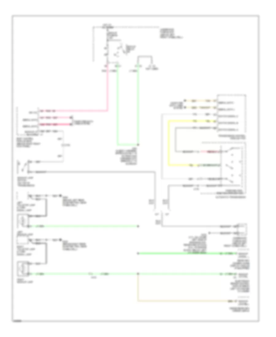
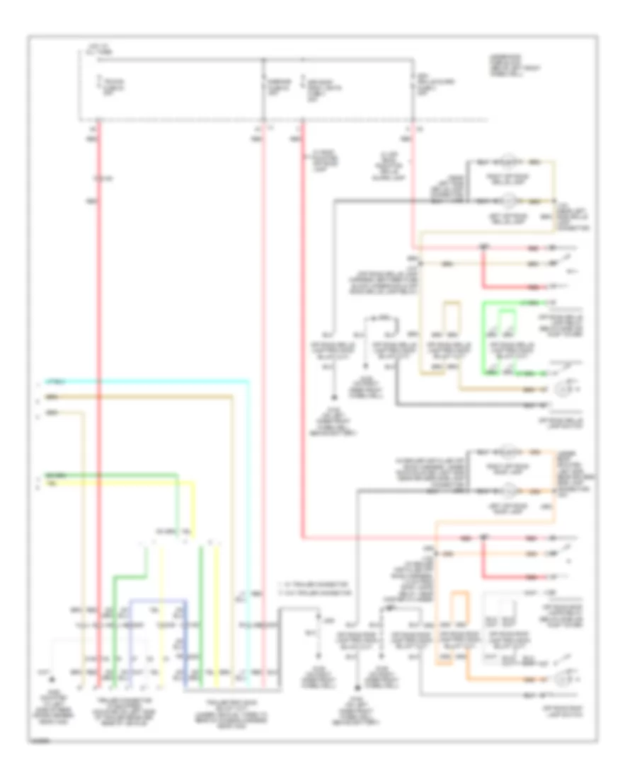
Backup Lamps Wiring Diagram for Hummer H3 2010
 https://portal-diagnostov.com/license.html
Automotive Electricians Portal FZCO
Automotive Electricians Portal FZCO
https://portal-diagnostov.com/license.html
https://portal-diagnostov.com/license.html
Automotive Electricians Portal FZCO
Automotive Electricians Portal FZCOList of elements for Backup Lamps Wiring Diagram for Hummer H3 2010:
- (not used)
- A/t
- A25
- A41
- A42
- Automatic transmission
- Backup lamp switch (on top of transmission)
- Backup lp ctrl
- Backup lp ctrl x2
- Backup lp rly ctrl x1
- Backup lp sig
- Bck/up fuse 60 15a
- Bck/up relay
- Body control module (bcm) (behind right front kick panel)
- Computer data lines system
- Electronic brake control module (ebcm) (left of master cylinder)
- G102 (3.7l: on lower left side of engine block, rearward of g103) (5.3l: on engine block, below left cylinder head)
- G340 (behind right rear quarter trim, near wheelwell)
- G350 (behind left rear quarter trim, near wheelwell)
- Hot at all times
- Ign vol
- Inside rearview mirror (isrvm)
- J224 (in body harness, approximately 15 cm from main harness into breakout to sunroof)
- Left backup lamp
- Left tail/stop lamp & turn signal lamp
- M/t
- Park/neutral position (pnp) switch
- Pnk
- Rearview camera image display module (if equipped)
- Right backup lamp
- Right tail/stop lamp & turn signal lamp
- Serial data
- Serial data +
- Serial data -
- Switch signal a
- Switch signal b
- Switch signal c
- Tan
- Transmission control module (tcm)
- Underhood fuse block (above left front wheelwell)
- X102
- X175
- X410
Exterior Lamps Wiring Diagram (1 of 3) for Hummer H3 2010
 https://portal-diagnostov.com/license.html
Automotive Electricians Portal FZCO
Automotive Electricians Portal FZCO
https://portal-diagnostov.com/license.html
https://portal-diagnostov.com/license.html
Automotive Electricians Portal FZCO
Automotive Electricians Portal FZCOList of elements for Exterior Lamps Wiring Diagram (1 of 3) for Hummer H3 2010:
- A10
- A19
- A24
- A26
- A28
- A37
- A45
- A48
- Auto
- Body control module (bcm) (behind right front kick panel)
- Center high mounted stop lamp (chmsl)
- Dealer installed
- Dimm sw sig
- Frt trn/ hazrd/ctsy mir fuse 56 15a
- Frt/prk fuse 43 10a
- G105 (on left inner front wheelwell, behind battery)
- G106 (on right inner front wheelwell)
- G350 (behind left rear quarter trim, near wheelwell)
- Haz sw sig
- Hazard switch
- Head
- Headlamp switch
- Hot at all times
- Interior lights system
- J109
- J185
- J205
- J215 (in body harness, approximately 14 cm to right of stop lamp switch breakout in main harness)
- J900
- Left
- Left front marker lamp
- Left park/ turn signal lamp
- Low ref
- Lr prk lp
- Lr stop/turn lamp ctrl
- Lr turn sig lamp ctrl
- Lt sig lp ctrl
- Off
- Park
- Park lamp relay 89
- Prk lmp rly
- Prk lmp sw
- Rear trn/ hazrd fuse 20 20a
- Red
- Right
- Right front marker lamp
- Right park/ turn signal lamp
- Rr stop/turn lamp ctrl
- Rr turn sig lamp ctrl
- Rt sig lp ctrl
- Stop fuse 50 15a
- Stop lamp switch (above brake pedal assembly)
- Stop lmp ctrl
- To lr prk fuse 37 (diagram 2 0f 3)
- Trn sig sw
- Turn signal/ multi-function switch
- Turn switch
- Underhood fuse block (above left front wheelwell)
- X115
- X116 h
- X117 e
- X201
- X450
- X901
Exterior Lamps Wiring Diagram (2 of 3) for Hummer H3 2010
 https://portal-diagnostov.com/license.html
Automotive Electricians Portal FZCO
Automotive Electricians Portal FZCO
https://portal-diagnostov.com/license.html
https://portal-diagnostov.com/license.html
Automotive Electricians Portal FZCO
Automotive Electricians Portal FZCOList of elements for Exterior Lamps Wiring Diagram (2 of 3) for Hummer H3 2010:
- Electronic brake control module (ebcm) (left of master cylinder)
- Engine control module (ecm) (right rear corner of engine compt)
- From a frt/prk fuse 43 (diagram 1 0f 3)
- Front middle roof clear- ance lamp
- G105 (on left inner front wheelwell, behind battery)
- G340 (behind right rear quarter trim, near wheelwell)
- G350 (behind left rear quarter trim, near wheelwell)
- G420 (mounted to left side of rear cross member, near x420)
- Ground distribution system
- Instrument panel cluster (ipc)
- J160
- J245 (approximately 26 cm rearward of left body pass through)
- J309
- J314
- J315
- J392
- J393
- J394
- J395
- J396
- J397
- J398
- J399
- Left front inner roof clear- ance lamp
- Left front outer roof clear- ance lamp
- Left tail/ stop & turn signal lamp
- Left turn ind
- License lamp
- Logic
- Lr prk fuse 37 10a
- Red
- Right front inner roof clear- ance lamp
- Right front outer roof clear- ance lamp
- Right tail/ stop & turn signal lamp
- Right turn ind
- Rr prk fuse 49 10a
- Stp lmp volt
- Transmission control module
- Trlr fuse 55 10a
- Underhood fuse block (above left front wheelwell)
- Volt stp lp
- W/ hd truck trailer
- W/ trailer connector
- W/o hd truck trailer wiring harness
- W/o trailer connector
- Wiring harness
- X102
- X150
- X410
- X420
- X430
Exterior Lamps Wiring Diagram (3 of 3) for Hummer H3 2010
 https://portal-diagnostov.com/license.html
Automotive Electricians Portal FZCO
Automotive Electricians Portal FZCO
https://portal-diagnostov.com/license.html
https://portal-diagnostov.com/license.html
Automotive Electricians Portal FZCO
Automotive Electricians Portal FZCOList of elements for Exterior Lamps Wiring Diagram (3 of 3) for Hummer H3 2010:
- (in dealer installed off road harness, under roof-mounted light bar near drivers side lamp connector) j302
- (near left side grille lamp connector) j105
- (under roof- mounted light bar near drivers side lamp connector) j301
- D5 x200
- D6 x200
- E-brake fuse 83 30a
- G105 (on left inner front wheelwell, behind battery)
- G106 (on right inner front wheelwell)
- G420 (mounted to left side of rear cross member, near x420)
- Hot at all times
- J101
- J102 (in dealer installed off road harness, 1.5 cm from roof lamps relay, near master cylinder)
- J103
- J107 (off road grille lamp harness, between fuse block underhood & off road grille lamp relay)
- J205
- Lamp connector)
- Left off road grille lamp
- Left off road roof lamp
- Off road grille lamp relay (below side air inlet cover)
- Off road grille lamp switch
- Off road roof lamp switch
- Off road roof lamps relay (below side air inlet cover)
- Red
- Right off road grille lamp
- Right off road roof lamp
- Spo grille guard fuse 2 20a
- Spo roof rack lights fuse 4 20a
- Trailer connector (if equipped) (mounted on left side of trailer receiver, rear of vehicle)
- Trlr b+ fuse 84 30a
- Underhood fuse block (above left front wheelwell)
- W/ off road radiator grille guard lamp
- W/ roof mounted off road lamp
- W/ trailer connector
- W/o trailer connector
- X150
- X420
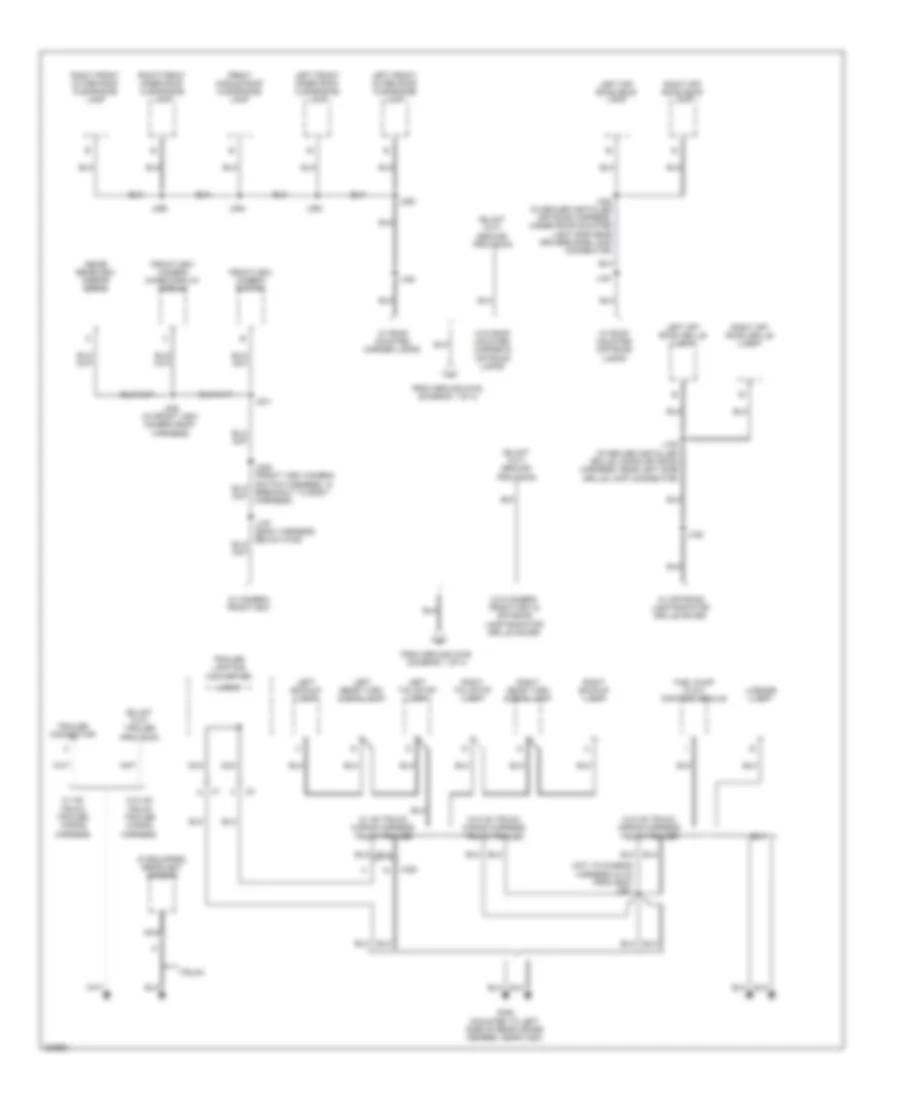
GROUND DISTRIBUTION
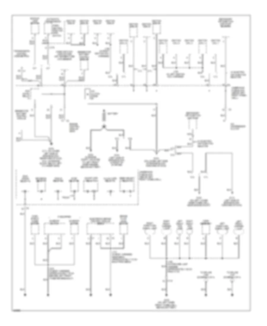
Ground Distribution Wiring Diagram (1 of 4) for Hummer H3 2010
 https://portal-diagnostov.com/license.html
Automotive Electricians Portal FZCO
Automotive Electricians Portal FZCO
https://portal-diagnostov.com/license.html
https://portal-diagnostov.com/license.html
Automotive Electricians Portal FZCO
Automotive Electricians Portal FZCOList of elements for Ground Distribution Wiring Diagram (1 of 4) for Hummer H3 2010:
- 3.7l
- 5.3l
- 87a
- A/c clutch diode
- A/c compressor clutch
- A/t
- Automatic transmission
- Backup lamp switch
- Battery
- Beem select relay 70
- Brake fluid level switch
- Electronic brake control module (ebcm)
- Engine control module (ecm)
- Fog/lp relay 69
- G100 (in engine compt, mounted to left front inner fender, behind battery)
- G102 (3.7l: on lower left side of engine block, rearward of g103) (5.3l: on engine block, below left cylinder head)
- G103 (on lower left side of engine block, forward of g102)
- G104 (left side of engine block, in front of starter)
- G105 (on left inner front wheelwell, behind battery)
- G110 (left side of engine block, forward of g103)
- G120 (on left lower inner wheelwell, near engine mount)
- Generator battery control module
- Hi/low wpr relay 73
- Horn assembly
- If equipped
- Ignition coil 1
- Ignition coil 2
- Ignition coil 3
- Ignition coil 4
- Ignition coil 5
- Ignition coil 6
- Ignition coil 7
- Ignition coil 8
- J110 (in body harness near ebcm, approximately 7.5 cm back from ebcm)
- J128 (in left ignition coil harness)
- J129 (in right ignition coil harness)
- J185 (in forward lamp harness, approximately 25 cm from x115)
- Left front fog lamp
- Left front marker lamp
- Left park/turn signal lamp
- M/t
- Mass air flow (maf)/intake air temperature (iat) sensor
- Nca
- On/off wpr relay 72
- Park/ neutral position (pnp) switch
- Pcm cntrl relay
- Right front fog lamp
- Right front marker lamp
- Right park/turn signal lamp
- Rr defog relay 71
- Run/ crank relay 78
- Secondary air injection (air) pump
- Secondary air injection (air) pump solenoid
- Stop relay 66
- Sunroof motor
- Sunroof switch
- To splice j157 (diagram 2 of 4)
- To splice j160 (diagram 2 of 4)
- Transmission control module (tcm)
- Truck
- Underhood fuse block (above left front wheel- well)
- Underhood fuse block (above left front wheelwell)
- W/ electric air injection reactor
- Wind- shield wiper motor
- X115
- X175 n
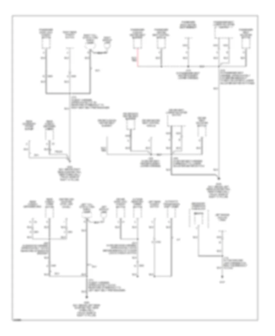
Ground Distribution Wiring Diagram (2 of 4) for Hummer H3 2010
 https://portal-diagnostov.com/license.html
Automotive Electricians Portal FZCO
Automotive Electricians Portal FZCO
https://portal-diagnostov.com/license.html
https://portal-diagnostov.com/license.html
Automotive Electricians Portal FZCO
Automotive Electricians Portal FZCOList of elements for Ground Distribution Wiring Diagram (2 of 4) for Hummer H3 2010:
- (h3t: in chassis harness 33 cm from g420) j361
- (if equipped) rearview camera
- From ground g105 (diagram 1 of 4)
- Front middle roof clearance lamp
- Frontview camera image display module
- Frontview camera switch
- Fuel pump flow control module
- G420 (mounted to left side of rear cross member, near x420)
- Inside rearview mirror (srvm)
- J105 (in dealer installed grille lamps off road harness, near left side grille lamp connector)
- J160
- J161
- J162
- J231
- J302 (in dealer installed off road harness, under roof-mounted light bar near drivers side lamp connector)
- J328 (in front view camera body harness)
- J392
- J393
- J394
- J395
- Left backup lamp
- Left front inner roof clearance lamp
- Left front outer roof clearance lamp
- Left off road grille lamp
- Left off road roof lamp
- Left rear turn signal lamp
- Left tail/stop lamp
- License lamp
- Logic
- Nca
- Right backup lamp
- Right front inner roof clearance lamp
- Right front outer roof clearance lamp
- Right off road grille lamp
- Right off road roof lamp
- Right rear turn signal lamp
- Right tail/stop lamp
- Suv
- Trailer connector
- Trailer lighting converter
- Truck
- W/ camera frontview
- W/ hd truck trailer wiring harness
- W/ hd truck wiring harness truck trailer
- W/ off-road lamp radiator grille gaurd
- W/ roof mounted marker lamps
- W/ roof mounted off-road lamps
- W/o camera frontview & off-road lamp radiator grille gaurd
- W/o hd truck trailer wiring harness
- W/o hd truck wiring harness truck trailer
- W/o roof mounted marker & off-road lamps
- X420
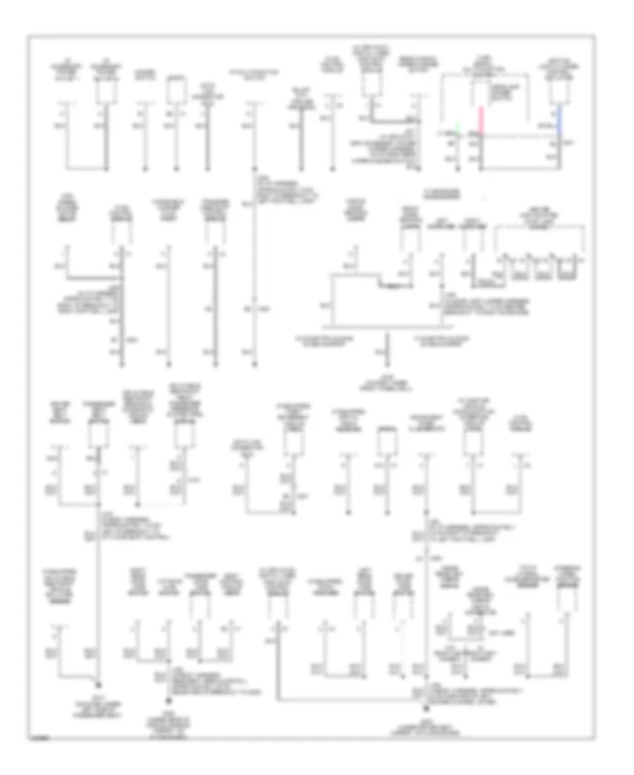
Ground Distribution Wiring Diagram (3 of 4) for Hummer H3 2010
 https://portal-diagnostov.com/license.html
Automotive Electricians Portal FZCO
Automotive Electricians Portal FZCO
https://portal-diagnostov.com/license.html
https://portal-diagnostov.com/license.html
Automotive Electricians Portal FZCO
Automotive Electricians Portal FZCOList of elements for Ground Distribution Wiring Diagram (3 of 4) for Hummer H3 2010:
- A/t
- Automatic transmission shift lever
- Center high mounted stop lamp (chmsl)
- Driver back heated seat element
- Driver cushion heated seat element
- Driver door lock/ window switch
- Driver heated seat control module
- Driver seat adjuster switch
- Driver seat lumbar adjuster switch
- G107
- G340 (suv: behind right rear quarter trim, near wheelwell) (truck: base of right "c" pillar)
- G345 (suv: behind left rear quarter trim, near wheelwell) (truck: base of right "c" pillar)
- G350 (suv: behind left rear quarter trim, near wheelwell) (truck: base of right "c" pillar)
- J118 (in the forward lamp harness 5 cm from the breakout to x103)
- J306 (in driver seat harness in breakout to lumbar adjuster/heater switch)
- J314 (in body harness, approximately 44.5 cm rearward of breakout to left seat belt pretensioner)
- J316 (in passenger seat harness, approximately 5 cm before breakout to seat adjuster & lumbar adjuster/heater switches)
- J318 (in passenger seat heater element jumper harness)
- J322 (in driver seat heater element jumper harness)
- J514 (in driver door harness, approximately 6.5 cm before breakouts to door lock & window switch)
- J900 (in endgate harness, approximately 19.5 cm rearward of endgate grommet)
- Left backup lamp
- Left engine cooling fan
- Left rear window switch
- Left tail/ stop & turn signal lamp
- Nca
- Outside rearview mirror switch
- Passenger back heated seat element
- Passenger cushion heated seat element
- Passenger door lock/ window switch
- Passenger heated seat control module
- Passenger seat adjuster switch
- Passenger seat lumbar adjuster switch
- Rear accessory power outlet
- Rear window defogger grid
- Rear window wiper motor
- Relay 2
- Right backup lamp
- Right rear window switch
- Right tail/ stop & turn signal lamp
- Secondary underhood fuse block
- Suv
- Truck
- X450
- X500
- X600
- X700
- X800
- X901
Ground Distribution Wiring Diagram (4 of 4) for Hummer H3 2010
 https://portal-diagnostov.com/license.html
Automotive Electricians Portal FZCO
Automotive Electricians Portal FZCO
https://portal-diagnostov.com/license.html
https://portal-diagnostov.com/license.html
Automotive Electricians Portal FZCO
Automotive Electricians Portal FZCOList of elements for Ground Distribution Wiring Diagram (4 of 4) for Hummer H3 2010:
- (if equipped) audio amplifier
- (if equipped) digital radio receiver
- (if equipped) inflatable restraint vehicle rollover sensor
- (if equipped) theft deterrent module (tdm)
- (w/ onstar) vehicle communication interface module (vcim)
- (w/ spo dvd1) digital video disc (dvd) control module
- (w/ spo dvd2) digital video disc (dvd) control module
- A12
- B10
- Body control module (bcm)
- Center high mounted stop lamp (chmsl)
- Data link connector (dlc)
- Driver door jamb switch
- Driver seat belt switch
- Front dome/ reading lamps
- G106 (on right inner front wheelwell)
- G300 (under driver seat carpet, on floor board)
- G310 (mounted under left side of passenger seat)
- G320 (under rear of middle console carpet, on floor board)
- Hazard switch
- Headlamp dimmer switch
- High speed blower motor relay
- Hvac control module
- I/p accessory power outlet 1
- I/p accessory power outlet 2
- I/p multi-function switch
- Ignition lock cylinder control actuator
- Inflatable restraint front passenger presence system (pps) module
- Inflatable restraint sensing & diagnostic module (sdm)
- Inside rearview mirror (isrvm)
- Inside rearview mirror (isrvm) connector
- Instrument panel cluster (ipc)
- J206 (in i/p harness, approximately 7 cm right of breakout to right footwell lamp)
- J300 (in body harness, approximately 20 cm forward of left rocker channel cover)
- J320 (in body harness rear seat area along sill, approximately 20 cm rearward of breakout to g320)
- J340 (in dome lamp jumper harness, approximately 10 cm before breakout to right sunshade)
- Left rear door jamb switch
- Left sunshade
- Liftgate ajar switch
- Middle dome/ reading lamps
- Nca
- Not used
- Passenger door jamb switch
- Passenger seat belt switch
- Pnk
- Radio
- Rear window wiper/washer switch
- Right rear door jamb switch
- Right sunshade
- Steering wheel position sensor
- To left footwell lamp)
- Transfer case shift control module
- Truck
- Turn signal/ multi-function switch
- W/ electric sliding glass sunroof
- W/ frontview camera
- W/ sunshade inside mirror
- W/o electric sliding glass sunroof
- W/o frontview camera
- Windshield washer fluid pump
- X1 a
- X200
- X201
- X201 b4
- X204
- X315
- Yaw & lateral accelerometer sensor
HEADLIGHTS
Headlights Wiring Diagram for Hummer H3 2010
 https://portal-diagnostov.com/license.html
Automotive Electricians Portal FZCO
Automotive Electricians Portal FZCO
https://portal-diagnostov.com/license.html
https://portal-diagnostov.com/license.html
Automotive Electricians Portal FZCO
Automotive Electricians Portal FZCOList of elements for Headlights Wiring Diagram for Hummer H3 2010:
- (in forward lamp harness, near center point of top of radiator, approximately 58 cm from x115)
- 15 cm from x115)
- 87a
- A x116
- A x117
- A10
- A11
- A18
- A31
- A36
- A37
- A39
- A43
- Ambient light sensor (right side of dash upper trim panel)
- Ambient lt sens
- Auto
- B x116
- B x117
- B10
- Beam select relay 70
- Body control module (bcm) (behind right front kick panel)
- Class 2 data
- Class 2 ser data
- Class 2 serial data
- Drl fuse 39 10a
- Drl ind logic
- Drl relay
- Drl rly ctrl
- Flash to pass
- Fog lmp ind
- Fog lp rly ctrl
- Fog lp sw sig
- Fog/lp fuse 24 15a
- Front fog lamp ind
- Front fog lamp switch
- Frt fog lp relay 69
- G105 (on left inner front wheelwell, behind battery)
- G106 (on right inner front wheelwell)
- Hdlp dim sw sig
- Hdlp off sig
- Hdlp on sig
- Hdlp relay
- Hdlp rly ctrl
- Head on
- Headlamp dimmer switch
- Headlamp switch
- Hi bm rly ctrl
- High beam
- High beam ind
- Hot at all times
- Ign
- Instrument panel cluster (ipc)
- J112 (in forward lamp harness, near left upper radiator support, approximately 48.5 cm from x115)
- J120
- J145
- J185 (in forward lamp harness, approximately 25 cm from x115)
- J205
- Left front fog lamp
- Left head- lamp
- Low ref
- Lt hdlp fuse 41 10a
- Off
- Park
- Park brake switch (left lower side of dash)
- Pk brake sw sig
- Pnk
- Red
- Right front fog lamp
- Right head- lamp
- Rt hdlp fuse 40 10a
- Turn signal/ multi-function switch
- Underhood fuse block (above left front wheelwell)
- X115
- X201
HORN
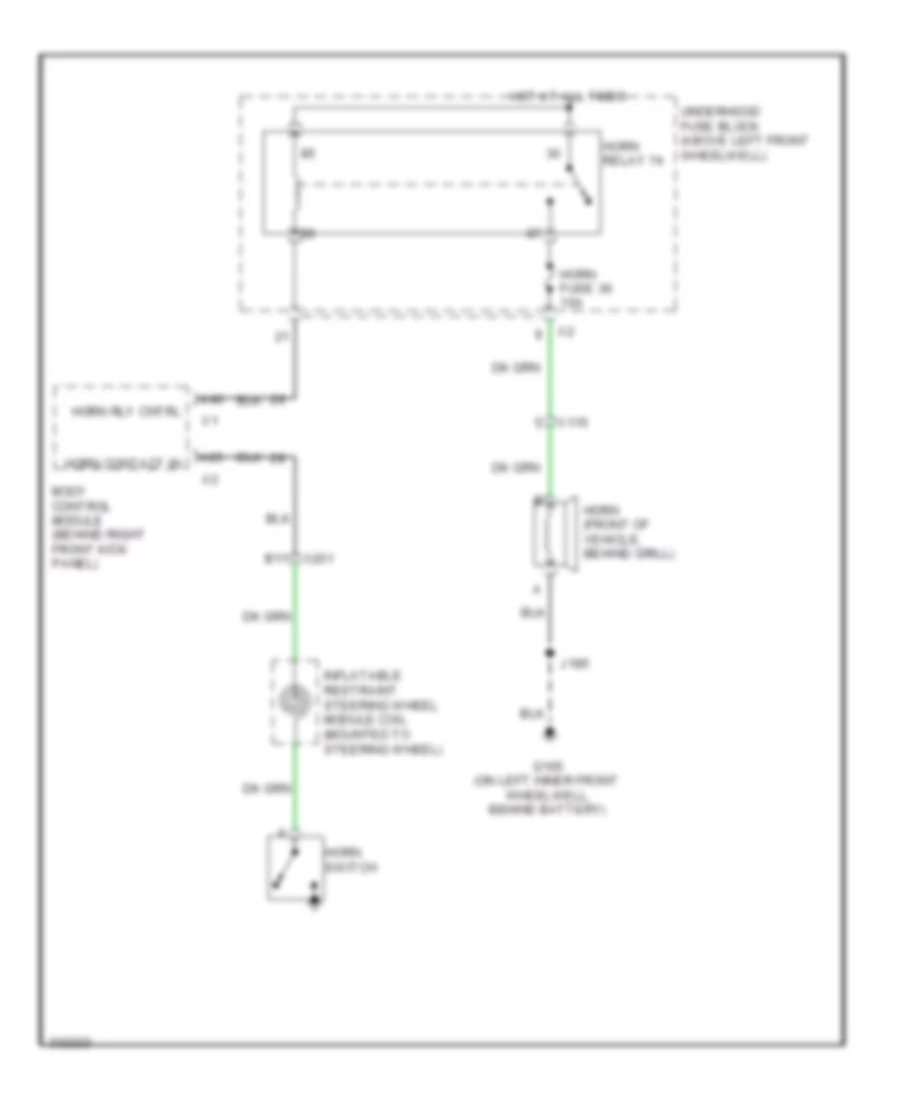
Horn Wiring Diagram for Hummer H3 2010
 https://portal-diagnostov.com/license.html
Automotive Electricians Portal FZCO
Automotive Electricians Portal FZCO
https://portal-diagnostov.com/license.html
https://portal-diagnostov.com/license.html
Automotive Electricians Portal FZCO
Automotive Electricians Portal FZCOList of elements for Horn Wiring Diagram for Hummer H3 2010:
- A25
- A40
- B11 x201
- Body control module (behind right front kick panel)
- G105 (on left inner front wheelwell, behind battery)
- Horn (front of vehicle, behind grill)
- Horn contact in
- Horn fuse 36 10a
- Horn relay 74
- Horn rly cntrl
- Horn switch
- Hot at all times
- Inflatable restraint steering wheel module coil (mounted to steering wheel)
- J185
- Underhood fuse block (above left front wheelwell)
- X115
INSTRUMENT CLUSTER
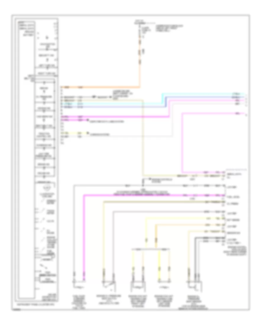
Instrument Cluster Wiring Diagram (1 of 2) for Hummer H3 2010
 https://portal-diagnostov.com/license.html
Automotive Electricians Portal FZCO
Automotive Electricians Portal FZCO
https://portal-diagnostov.com/license.html
https://portal-diagnostov.com/license.html
Automotive Electricians Portal FZCO
Automotive Electricians Portal FZCOList of elements for Instrument Cluster Wiring Diagram (1 of 2) for Hummer H3 2010:
- (under driver seat carpet, on floor board) g300
- 3.7l
- 5 volt ref 1
- 5.3l
- A nca
- Abs ind
- Air bag ind
- B nca
- B10
- Battery
- Brake ind
- Charging ind
- Chime
- Clstr fuse 19 10a
- Computer data lines system
- Cruise ind
- Driver information center (dic)
- Ect sense
- Engine control module (ecm) (right rear corner of engine compt)
- Engine controls system
- Engine coolant
- Engine coolant temper- ature gauge
- Engine coolant temperature (ect) sensor (front left of engine)
- Engine oil pressure (eop) sensor (5.3l) (top of engine near rear of intake manifold)
- Engine oil pressure (eop) switch (3.7l) (above oil filter)
- Fuel gauge
- Fuel level
- Fuel pump & sender assembly (mounted on top of fuel tank)
- Ground
- High beam ind
- Hot at all times
- Ign
- Illumination (4 bulbs)
- Instrument panel cluster (ipc)
- J251
- J359 (in chassis harness, approximately 22.5 cm from fuel pump & sender assembly connector)
- Left turn ind
- Logic
- Low ref
- Low tire pressure ind
- Malfunction ind
- Mil
- Oil gauge
- Oil press
- Oil pressure ind
- Right turn ind
- Seat belt ind
- Security ind
- Sensor sig
- Serial data
- Speedo- meter
- Tacho- meter
- Tan
- Temperature (ect) sensor (left side of engine)
- Traction control ind
- Trip/ odometer
- Trip/ reset switch
- Underhood fuse block (above left front wheelwell)
- Upshift ind
- Volts
- Warning system
- X150
- X200
- X204
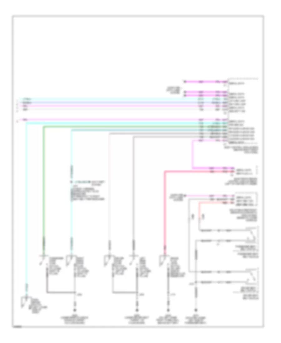
Instrument Cluster Wiring Diagram (2 of 2) for Hummer H3 2010
 https://portal-diagnostov.com/license.html
Automotive Electricians Portal FZCO
Automotive Electricians Portal FZCO
https://portal-diagnostov.com/license.html
https://portal-diagnostov.com/license.html
Automotive Electricians Portal FZCO
Automotive Electricians Portal FZCOList of elements for Instrument Cluster Wiring Diagram (2 of 2) for Hummer H3 2010:
- A19
- A26
- A31
- A32
- A38
- A39
- A41
- A42
- A44
- A47
- Anti-theft system
- Body control module (bcm) (behind right front kick panel)
- Brake fluid level switch (on left side of brake fluid reservoir)
- Brk fluid lvl
- Computer data lines system
- Driver door ajar switch (in lower left "b" pillar)
- Driver seat belt buckle
- Driver seat belt switch
- Electronic brake control module (ebcm) (left of master cylinder)
- G105 (on left inner front wheelwell, behind battery)
- G300 (under driver seat carpet, on floor board)
- G310 (mounted under left side of passenger seat)
- G320 (under rear of middle console carpet, on floor board)
- Inflatable restraint sensing & diagnostic module (sdm) (beneath lower console)
- J110
- J300
- J310
- J320
- J347 (in body harness, approximately 42 cm rearward of breakout to right seat belt pretensioner)
- Left rear door ajar switch (in lower left "c" pillar)
- Lf door ajar sw sig
- Lr door ajar sw sig
- Lr turn lamp
- Nca
- Park brake switch (left lower side of dash)
- Passenger door ajar switch (in lower right "b" pillar)
- Passenger seat belt buckle
- Passenger seat belt switch
- Pnk
- Prk brk sw
- Red
- Rf door ajar sw sig
- Right rear door ajar switch (in lower right "c" pillar)
- Rr door ajar sw sig
- Rr turn lamp
- Seat belt sw
- Security ind
- Serial data
- X308
- X320
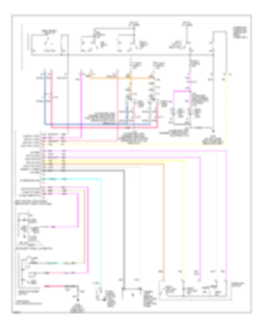
INTERIOR LIGHTS
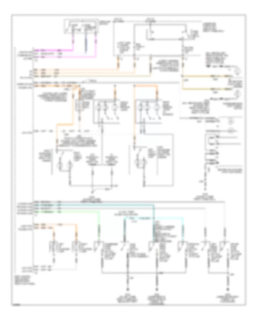
Courtesy Lamps Wiring Diagram for Hummer H3 2010
 https://portal-diagnostov.com/license.html
Automotive Electricians Portal FZCO
Automotive Electricians Portal FZCO
https://portal-diagnostov.com/license.html
https://portal-diagnostov.com/license.html
Automotive Electricians Portal FZCO
Automotive Electricians Portal FZCOList of elements for Courtesy Lamps Wiring Diagram for Hummer H3 2010:
- (in body harness, approximately 6 cm to right of stop lamp switch breakout in main harness)
- (in dome lamp jumper harness, approximately 5 cm before breakout to right sunshade)
- (suv: behind left rear quarter trim, near wheelwell) (track: base of right "c" pillar) g350
- A10
- A11
- A12
- A24
- A30
- A32
- A38
- A39
- A40
- A41
- A44
- A46
- A47
- Bcm fuse 14 10a
- Body control module (bcm) (behind right front kick panel)
- Cargo sw sig
- Center high mounted stop lamp (chmsl)
- Dome lamp (suv)
- Dome on switch
- Dome override switch
- Driver door ajar switch (in lower left "b" pillar)
- Driver door lock/window switch
- Endgate ajar switch (suv) (in right "d" pillar)
- Front dome/ reading lamps (w/ sunroof)
- Frt prk fuse 43 10a
- Frt turn/ hazard/ ctsy mir fuse 56 15a
- G105 (on left inner front wheelwell, behind battery)
- G106 (on right inner front wheelwell)
- G300 (under driver seat carpet, on floor board)
- G320 (under rear of middle console carpet, on floor board)
- G340 (suv: behind right rear quarter trim, near wheelwell) (track: base of right "c" pillar)
- Headlamp switch
- Hood ajar switch (suv) (part of hood latch assembly)
- Hot at all times
- J185
- J209
- J300
- J315
- J320
- J330 (suv & truck w/ sunroof & inside front van mirror) b
- J340
- J350 (truck w/ sunroof & suv) (in dome lamp jumper harness, approximately 5 cm before breakout to dome/reading lamp)
- J514
- Lamp ctrl
- Lamp sw sig
- Left i/p courtesy lamp
- Left rear door ajar switch (in lower left "c" pillar)
- Left sunshade (w/ inside front van mirror)
- Left vanity mirror lamp
- Lf door ajar
- Low ctrl
- Low ref
- Lr door ajar
- Middle dome/ reading lamps
- Nca
- Override sw
- Park lamp relay
- Passenger door ajar switch (in lower right "b" pillar)
- Passenger door lock/ window switch
- Pk lp ctrl
- Power ctrl
- Rf door ajar
- Right i/p courtesy lamp
- Right rear door ajar switch (in lower right "c" pillar)
- Right sunshade (w/ inside front van mirror)
- Right vanity mirror lamp
- Rr door ajar
- Truck
- Underhood fuse block (above left front wheelwell)
- W/ anti theft cover lock control
- W/ sunroof & inside front van mirror
- W/o sunroof & inside front van mirror
- X115
- X350
- X351
- X500
- X600
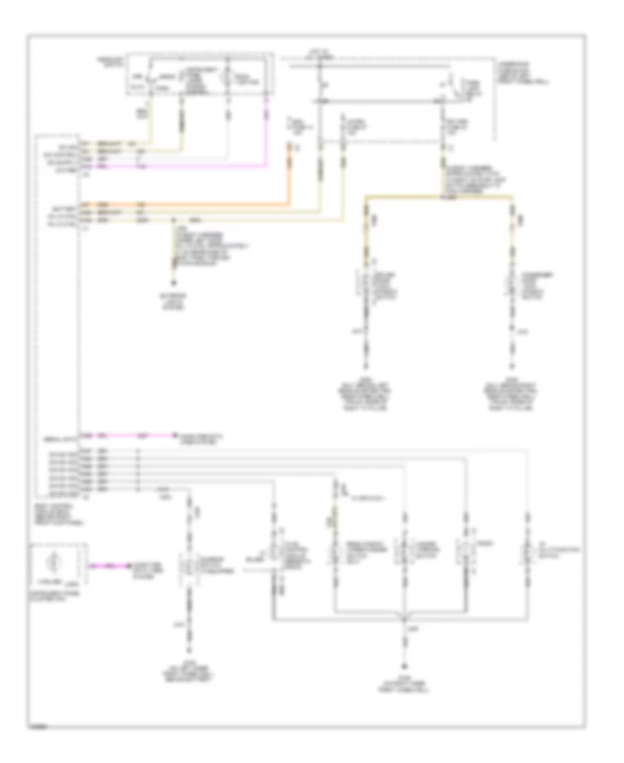
Instrument Illumination Wiring Diagram for Hummer H3 2010
 https://portal-diagnostov.com/license.html
Automotive Electricians Portal FZCO
Automotive Electricians Portal FZCO
https://portal-diagnostov.com/license.html
https://portal-diagnostov.com/license.html
Automotive Electricians Portal FZCO
Automotive Electricians Portal FZCOList of elements for Instrument Illumination Wiring Diagram for Hummer H3 2010:
- (4 bulbs)
- (5 bulbs)
- (in body harness, approximately 6 cm to right of stop lamp switch breakout in main harness) j209
- A10
- A24
- A27
- A28
- A29
- A30
- A33
- A34
- A36
- A39
- A48
- Auto
- Back lighting
- Battery
- Bcm fuse 14 10a
- Body control module (bcm) (behind right front kick panel)
- Computer data lines system
- Dim control
- Dim sw sig
- Driver door lock/ window switch x1
- Exterior lights system
- Frt prk fuse 43 10a
- G105 (on left inner front wheelwell, behind battery)
- G106 (on right inner front wheelwell)
- G340 (suv: behind right rear quarter trim, near wheelwell) (truck: base of right "c" pillar)
- G350 (suv: behind left rear quarter trim, near wheelwell) (truck: base of right "c" pillar)
- Hazard warning switch
- Head
- Headlamp switch
- Hot at all times
- Hvac control module (beneath radio)
- I/p multi-function switch
- Instrument panel cluster (ipc)
- Instrument panel lamps dimming control
- J205
- J210
- J315
- J514
- Logic
- Low ref
- Lr prk fuse 37 10a
- Off
- Park
- Park lamp relay
- Passenger door lock/ window switch
- Pk lp ctrl
- Radio
- Rear window wiper/washer switch (suv)
- Serial data
- Sunroof switch (if equipped)
- Sw sig
- Underhood fuse block (above left front wheelwell)
- W/ spo dvd 1
- X204
- X270
- X335
- X500
- X600
NAVIGATION
Front View Camera Wiring Diagram for Hummer H3 2010
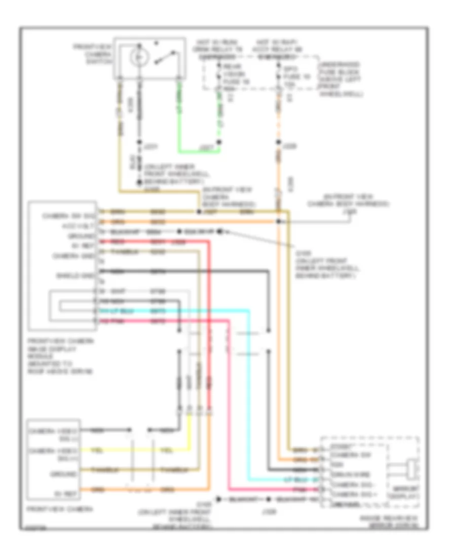 https://portal-diagnostov.com/license.html
Automotive Electricians Portal FZCO
Automotive Electricians Portal FZCO
https://portal-diagnostov.com/license.html
https://portal-diagnostov.com/license.html
Automotive Electricians Portal FZCO
Automotive Electricians Portal FZCOList of elements for Front View Camera Wiring Diagram for Hummer H3 2010:
- (in front view camera body harness) j326
- (in front view camera body harness) j327
- (on left inner front wheelwell, behind battery) g105
- 6v ref
- Acc volt
- Camera gnd
- Camera sig +
- Camera sig -
- Camera sw
- Camera sw sig
- Camera video sig (+)
- Camera video sig (-)
- Drain wire
- Frontview camera
- Frontview camera switch
- G105 (on left front inner wheelwell, behind battery)
- G105 (on left inner front wheelwell, behind battery)
- Ground
- Hot w/ rap/ accy relay 88 energized
- Hot w/ run/ crnk relay 78 energized
- Ign
- Image display module (mounted to roof above isrvm)
- Inside rearview mirror (isrvm)
- J227
- J228
- J231
- J328
- Logic
- Mirror display
- Nca
- Pnk
- Rear vision fuse 18 10a
- Red
- Shield gnd
- Spo fuse 10 10a
- Underhood fuse block (above left front wheelwell)
- X206
Navigation Wiring Diagram for Hummer H3 2010
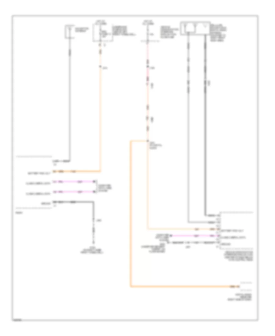 https://portal-diagnostov.com/license.html
Automotive Electricians Portal FZCO
Automotive Electricians Portal FZCO
https://portal-diagnostov.com/license.html
https://portal-diagnostov.com/license.html
Automotive Electricians Portal FZCO
Automotive Electricians Portal FZCOList of elements for Navigation Wiring Diagram for Hummer H3 2010:
- 10a
- Battery pos volt
- Cellular, navigation & digital radio antenna (mounted to right front roof area)
- Class 2 serial data
- Coax
- Computer data lines system
- Digital radio receiver (right side of dash)
- G106 (on right inner front wheelwell)
- G300 (under driver seat carpet, on floor board)
- Ground
- Hot at all times
- J106
- J205
- J214
- J234 (w/ digital audio)
- J251
- L-gr
- Navigation antenna
- Radio
- Rdo fuse 13 15a
- Red
- Underhood fuse block (above left front wheelwell)
- Vehicle communication interface module (vcim) (center of dash below hvac control head)
- Vehicle communication interface module (vcim) inline fuse
- X130
- X200
- X222
Rear View Camera Wiring Diagram for Hummer H3 2010
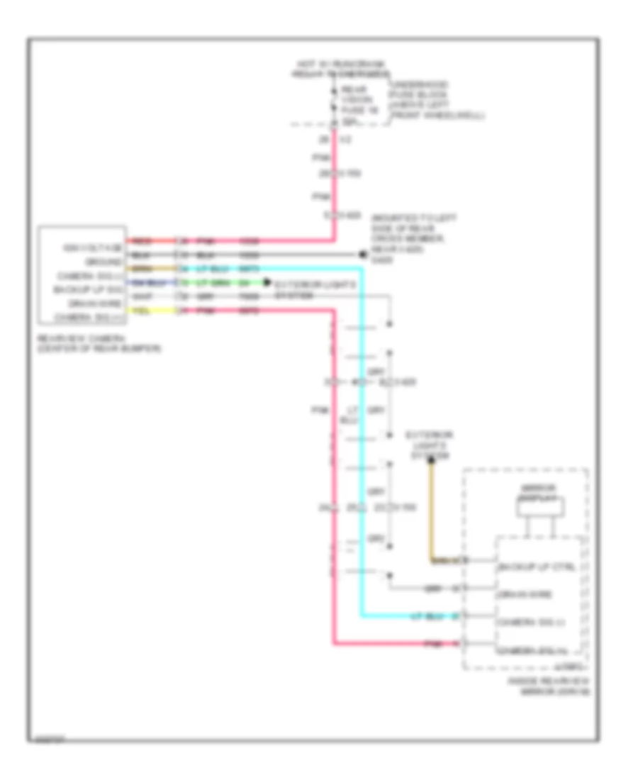 https://portal-diagnostov.com/license.html
Automotive Electricians Portal FZCO
Automotive Electricians Portal FZCO
https://portal-diagnostov.com/license.html
https://portal-diagnostov.com/license.html
Automotive Electricians Portal FZCO
Automotive Electricians Portal FZCOList of elements for Rear View Camera Wiring Diagram for Hummer H3 2010:
- (mounted to left side of rear cross member, near x420) g420
- Backup lp ctrl
- Backup lp sig
- Camera sig (+)
- Camera sig (-)
- Drain wire
- Exterior lights system
- Ground
- Hot w/ run/crank relay 78 energized
- Ign voltage
- Inside rearview mirror (isrvm)
- Logic
- Mirror display
- Pnk
- Rear vision fuse 18 10a
- Rearview camera (center of rear bumper)
- Red
- Underhood fuse block (above left front wheelwell)
- X150
- X420
POWER DISTRIBUTION
Power Distribution Wiring Diagram (1 of 4) for Hummer H3 2010
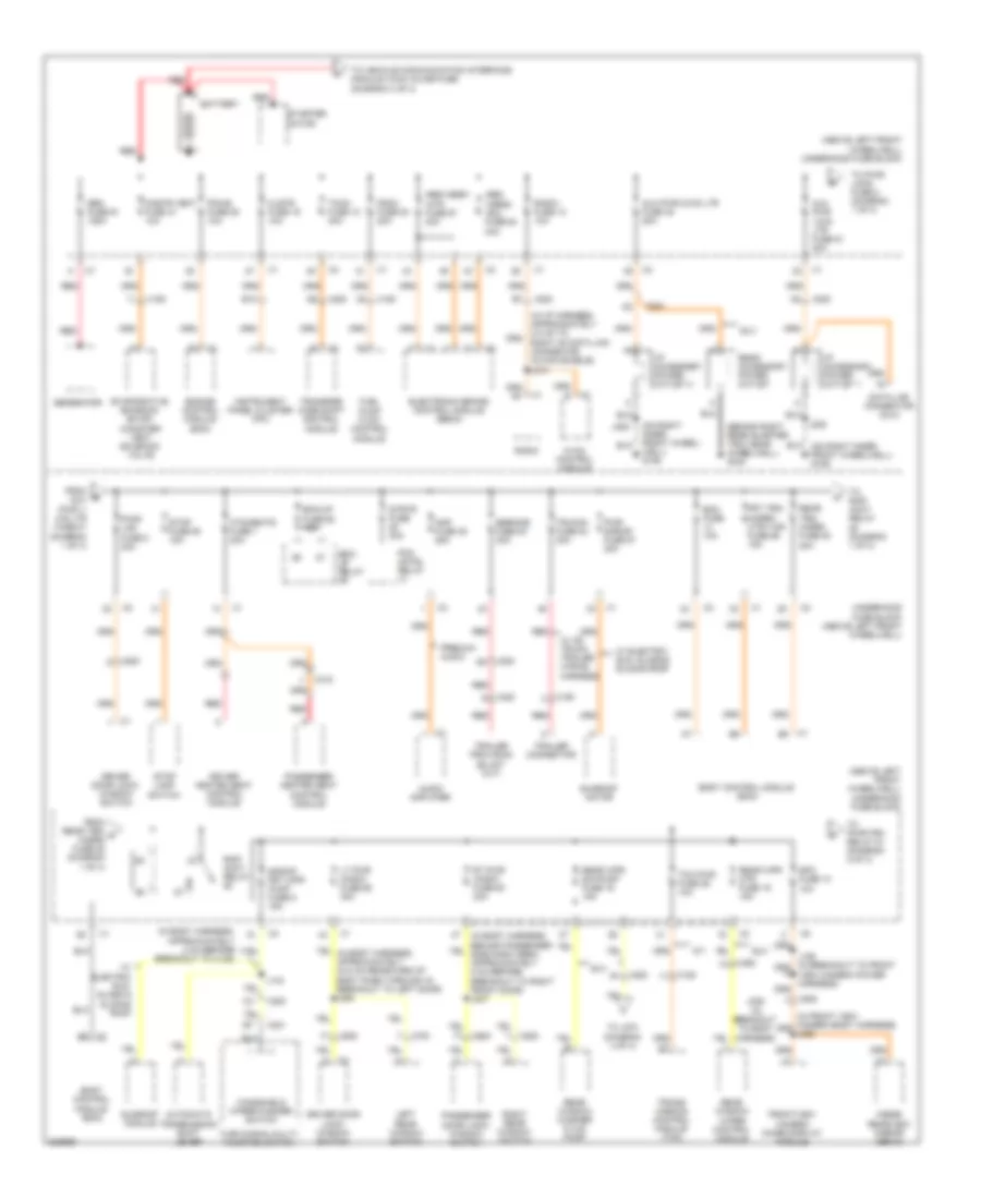 https://portal-diagnostov.com/license.html
Automotive Electricians Portal FZCO
Automotive Electricians Portal FZCO
https://portal-diagnostov.com/license.html
https://portal-diagnostov.com/license.html
Automotive Electricians Portal FZCO
Automotive Electricians Portal FZCOList of elements for Power Distribution Wiring Diagram (1 of 4) for Hummer H3 2010:
- (above left front wheelwell) underhood fuse block
- (behind right rear quarter trim, near wheelwell) g340
- (in body harness, approximately 2 cm before breakout to x125)
- (in front view camera body harness) j326
- (in i/p harness, approximately 2.5 cm to right of data link connector in main bundle) j214
- (on right inner front wheel- well) g106
- (on right inner front wheelwell) g106
- A/t
- Abs/ vses2 -sol fuse 64 30a
- Abs/vses1 -mtr fuse 67 40a
- Amp fuse 38 25a
- Audio amplifier
- Automatic transmission shift lever
- Aux pwr 1/cig ltr fuse 51 20a
- Aux pwr 2/cig ltr fuse 45 20a
- B10
- Battery
- Bck/ up relay
- Bck/up fuse 60 15a
- Bcm fuse 10a
- Body control module (bcm)
- Clstr fuse 19 10a
- Cnstr vent fuse 31 10a
- Data link connector (dlc)
- Driver door lock/ window switch
- Driver heated seat control module
- E-brake fuse 83 30a
- Electronic brake control module (ebcm)
- Engine control module (ecm)
- Evaporative emission (evap) canister vent solenoid valve
- From b aux pwr 1/ cig ltr fuse 51 (diagram 1 of 4)
- From rear trn/ c hazrd fuse 20 (diagram 1 of 4)
- Frontview camera image display module
- Frt trn/ hazrd/ ctsy mir fuse 56 15a
- Fscm fuse 54 20a
- Fuel pump flow control module
- Gen fuse 91 125a
- Generator
- Htd/seats fuse 1 20a
- Hvac control module
- I/p accessory power outlet 1
- I/p accessory power outlet 2
- Inside rearview mirror (isrvm)
- Instrument panel cluster (ipc)
- J143
- J158 (in breakout to front view camera power harness)
- J205
- J228 (in breakout to body harness)
- Left rear window switch
- Lt pwr wndw fuse 68 30a
- Passenger door lock/ window switch
- Passenger heated seat control module
- Pcm cntrl relay
- Pcm-b fuse 25 10a
- Premium audio
- Pwr s/roof fuse 57 30a
- Pwr/ lks fuse 8 20a
- Radio
- Radio fuse 13 10a
- Rap/ accy relay
- Rear accessory power outlet
- Rear trn/ hazrd fuse 20 20a
- Rear window washer fluid pump
- Rear window wiper control module
- Rear wpr mtr fuse 15 15a
- Rear wpr sw/pump fuse 16 15a
- Red
- Right rear window switch
- Rt pwr wndw fuse 63 30a
- S/roof frt wpr pump fuse 9 15a
- Spo fuse 10 10a
- Starter motor
- Stop fuse 50 15a
- Stop lamp switch
- Strtr fuse 30a
- Sunroof module
- Sunroof motor
- Suv
- Tccm fuse 12 30a
- Tcm pwr fuse 26 10a
- To j270 (diagram 4 of 4)
- To pwr/ loks fuse 8 (diagram 1 of 4)
- To pwr/trn relay 81 (diagram 2 of 4)
- To rap/ accy relay (diagram 1 of 4)
- To vehicle communication interface module (vcim) inline fuse (diagram 4 of 4)
- Trailer connector
- Trans- mission control module (tcm)
- Transfer case shift control module
- Trlr b+ fuse 84 30a
- Turn signal/multi- function switch
- Underhood fuse block (above left front wheelwell)
- W/ electric sun, glass & sliding roof
- W/ hd truck trailer wiring harness
- Windshield wiper/washer switch
- X125
- X150
- X200
- X201
- X204
- X206
- X315
- X420
- X450
- X500
- X600
- X700
- X800
Power Distribution Wiring Diagram (2 of 4) for Hummer H3 2010
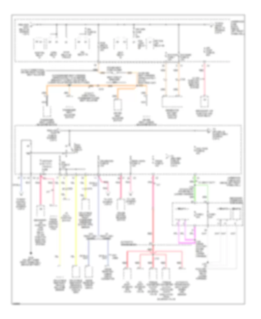 https://portal-diagnostov.com/license.html
Automotive Electricians Portal FZCO
Automotive Electricians Portal FZCO
https://portal-diagnostov.com/license.html
https://portal-diagnostov.com/license.html
Automotive Electricians Portal FZCO
Automotive Electricians Portal FZCOList of elements for Power Distribution Wiring Diagram (2 of 4) for Hummer H3 2010:
- (3.7l)
- (5.3l)
- (in driver seat harness, approximately 28.5 cm back from x307) j312
- (in passenger seat harness, approximately 10 cm before breakout to seat adjuster & lumbar adjuster/heater switches) j341
- 1-2 shift solenoid (ss) valve
- 2-3 shift solenoid (ss) valve
- A/t
- Air pump fuse 62 60a
- Air pump rly
- Automatic transmission
- Automatic transmission input shaft speed (iss) sensor
- Cool fans fuse 62 40a
- Cruise control release switch
- Cruise/misc fuse 35 10a
- Driver seat adjuster switch
- Driver seat lumbar adjuster switch
- Drl fuse 39 10a
- Drl relay 79
- Fog lamp relay
- From air e pump fuse 62 (diagram 2 of 4)
- From rap/ d accy relay 88 (diagram 1 of 4)
- Frt fog lmp relay 69
- Frt/wpr fuse 25a
- Fuse 1 20a
- Fuse 10a
- Fuse 2 20a
- G105 (on left inner front wheelwell, behind battery)
- Generator battery control module
- Hdlp relay
- Horn relay
- I/p multi- function switch
- Inflatable restraint front passenger presence system (pps) sensor
- Inflatable restraint sensing & diagnostic module (sdm)
- Inflatable restraint vehicle rollover sensor
- Inside rearview mirror (isrvm)
- Inside rearview mirror (isrvm) connector
- J123 (in auxiliary power relay jumper harness)
- J124 (in auxiliary power relay jumper harness)
- J125 (inside auxiliary power relay jumper harness)
- J133
- Nca
- Not used
- Passenger seat adjuster switch
- Passenger seat lumbar adjuster switch
- Pnk
- Power seat fuse holder
- Pwr seats fuse 61 40a
- Pwr/trn relay
- Rear vision fuse 18 10a
- Red
- Relay 1
- Relay 2
- Relay 3
- Run/ crnk relay
- Rvc pwr fuse 7 10a
- Rvc snsr fuse 32 10a
- Seat circuit breaker 25a
- Secondary air injection (air) pump relay
- Secondary air injection (air) pump relay (w/ air injection electric reactor system)
- Secondary underhood fuse block
- Sir fuse 27 10a
- Stop relay 66 (truck)
- Tcm
- To abs/vses fuse 29 (diagram 3 of 4)
- To body control module (diagram 4 of 4)
- To j159 (diagram 4 of 4)
- To j272 (diagram 4 of 4)
- To run/ crank relay 78 (diagram 2 of 4)
- To spo grille guard fuse 2 (diagram 3 of 4)
- Torque converter clutch (tcc) pulse width modulation (pwm) solenoid valve
- Torque converter clutch (tcc) solenoid valve
- Trans fuse 34 10a
- Trans- mission control module (tcm)
- Underhood fuse block (above left front wheelwell)
- W/ air injection electric reactor system
- W/ front view camera
- W/ heavy duty
- W/ multi directional driver front power seat adjuster
- W/ multi directional passenger power seat adjuster
- W/o front view camera
- X125
- X200
- X315
Power Distribution Wiring Diagram (3 of 4) for Hummer H3 2010
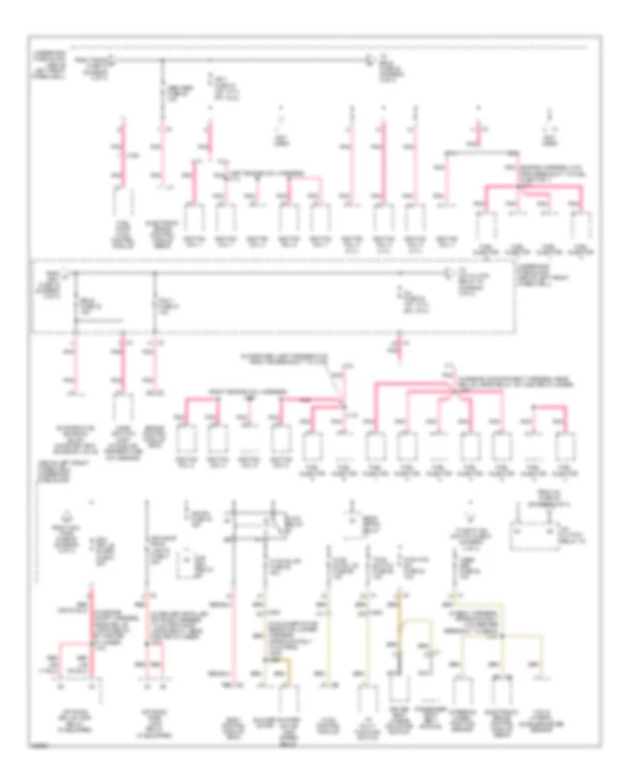 https://portal-diagnostov.com/license.html
Automotive Electricians Portal FZCO
Automotive Electricians Portal FZCO
https://portal-diagnostov.com/license.html
https://portal-diagnostov.com/license.html
Automotive Electricians Portal FZCO
Automotive Electricians Portal FZCOList of elements for Power Distribution Wiring Diagram (3 of 4) for Hummer H3 2010:
- (3.7l) (5.3l)
- (above left front wheelwell) underhood fuse block
- (if equipped)
- (in blower motor resistor jumper harness, approximately 15 cm from x203) j220
- (in body harness, approximately 5 cm before breakout to ebcm) j141
- (in dealer installed off road harness, 1.5 cm from roof lamps relay, near master cylinder) j101
- (in engine compartment harness, near grille lamps relay, by master cylinder) j103
- (in engine compt harness, near grille lamps relay, by master cylinder) j103
- (in forward lamp harness 5 cm from the breakout to x103)
- (left engine coil harness) j113
- (not used)
- (right engine coil harness) j116
- 3.7l
- 5.3l
- A/c clutch/ relay 76
- A26
- Abs/vses fuse 29 10a
- Air sol fuse 44 15a
- Air sol relay
- Blower motor
- Blower motor high speed relay
- Body control module (bcm)
- C11
- Driver seat lumbar adjuster switch
- Electronic brake control module (ebcm)
- Engine control module (ecm)
- Erls fuse 22 15a
- Evaporative emission (evap) canister vent solenoid valve
- From cool fans fuse 62 (diagram 2 of 4)
- From inj fuse 23 (diagram 3 of 4)
- From o ign-1 fuse 33 (diagram 3 of 4)
- From trans f fuse 34 (diagram 2 of 4)
- Fuel injector
- Fuel pump flow control module
- Hvac blwr fuse 82 30a
- Hvac cntrl hd fuse 59 10a
- Hvac control module
- Hvac relay
- I/p multi- function switch
- Ign-1 fuse 33 15a 20a
- Ignition coil 1
- Ignition coil 2
- Ignition coil 2 (3.7l)
- Ignition coil 3
- Ignition coil 3 (3.7l)
- Ignition coil 4
- Ignition coil 5
- Ignition coil 5 (3.7l)
- Ignition coil 6
- Ignition coil 7
- Ignition coil 8
- Inj fuse 23 15a 20a
- J118
- Mass air flow (maf)/ intake air temperature (iat) sensor
- Nca
- Off road grille lamp relay (if equipped)
- Off road roof lamp relay
- Passenger seat belt buckle
- Pcm 1 fuse 21 10a
- Pnk
- Pnk (engine harness, 5 cm from breakout to fuel injector 1) j111
- Pwr htr sw fuse 53 10a
- Rear defog relay
- Red
- Spo grille guard fuse 2 20a
- Spo roof rack lights fuse 4 20a
- Steering wheel position sensor
- Tccm switch fuse 58 10a
- To a/c clutch relay 76 (diagram 3 of 4)
- To batt ign switch fuse 5 (diagram 4 of 4)
- To erls fuse 22 (diagram 3 of 4)
- Underhood fuse block (above left front wheelwell)
- Vses/ abs fuse 52 10a
- X1 d
- X150
- X200 a3
- X200 d8
- Yaw & lateral accelerometer sensor
Power Distribution Wiring Diagram (4 of 4) for Hummer H3 2010
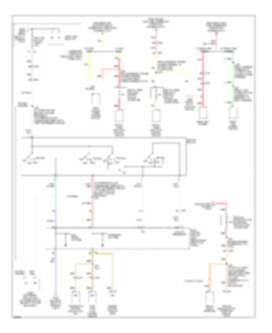 https://portal-diagnostov.com/license.html
Automotive Electricians Portal FZCO
Automotive Electricians Portal FZCO
https://portal-diagnostov.com/license.html
https://portal-diagnostov.com/license.html
Automotive Electricians Portal FZCO
Automotive Electricians Portal FZCOList of elements for Power Distribution Wiring Diagram (4 of 4) for Hummer H3 2010:
- (a/t)
- (in steering column harness between x201 & red
- (w/ spo dvd2) j272
- 10a
- 5-volts reference
- A14
- Acc
- Accessory voltage
- Batt ign switch fuse 5 10a
- Body control module (bcm) (behind right front kick panel)
- Digital radio receiver
- Digital video disc (dvd) control module
- Digital video disc (dvd) control module inline fuse
- Digital video disc (dvd) control module inline fuse (w/ spo dvd2)
- Engine control module (ecm)
- From battery a (diagram 1 of 4)
- From cruise/ misc fuse (underhood fuse block) (diagram 2 of 4)
- From k rear defog relay 71 (diagram 3 of 4)
- From rear vision fuse (underhood fuse block) (diagram 2 of 4)
- From rear wpr sw/pump fuse 16 (underhood fuse block) (diagram 1 of 4)
- From run/crnk relay 78 (diagram 2 of 4)
- Front view camera switch
- Fuel pump flow control module
- Ign
- Ignition switch
- J106 (engine harness, on breakout to x130)
- J159 (body harness, in breakout to front view camera power harness)
- J200 (w/ immobilization security system equipment) (in steering column harness between x200 & theft deterrent module)
- J207
- J227 (front view camera switch harness, in breakout to body harness)
- J234 (w/ digital audio) (in i/p harness center dash area, approximately 5 cm left of breakouts to hvac in main bundle)
- J270 (spo accessory power jumper harness, 10 cm from rear wiper/washer switch)
- Off
- Park lamp relay 89
- Pnk
- Rear view camera
- Rear window wiper/ washer switch
- Red
- Run
- Run/ crank voltage
- Start
- Theft deterrent module (tdm) (w/ immobilization security system equipment)
- Theft deterrent module) (w/ immobilization security system equipment) j201
- Transmision control module (tcm) (a/t)
- Turn signal/ multi- function switch
- Underhood fuse block (above left front wheelwell)
- Vehicle communication interface module (vcim)
- Vehicle communication interface module (vcim) inline fuse
- W/ digital audio
- W/ front view camera
- W/ rear view camera
- W/ spo dvd1
- W/o spo dvd1
- X102
- X150
- X2 a42
- X200
- X200 b8
- X200 b9
- X201 a8
- X201 b1
- X201 b3
- X420
POWER DOOR LOCKS
Power Door Locks Wiring Diagram for Hummer H3 2010
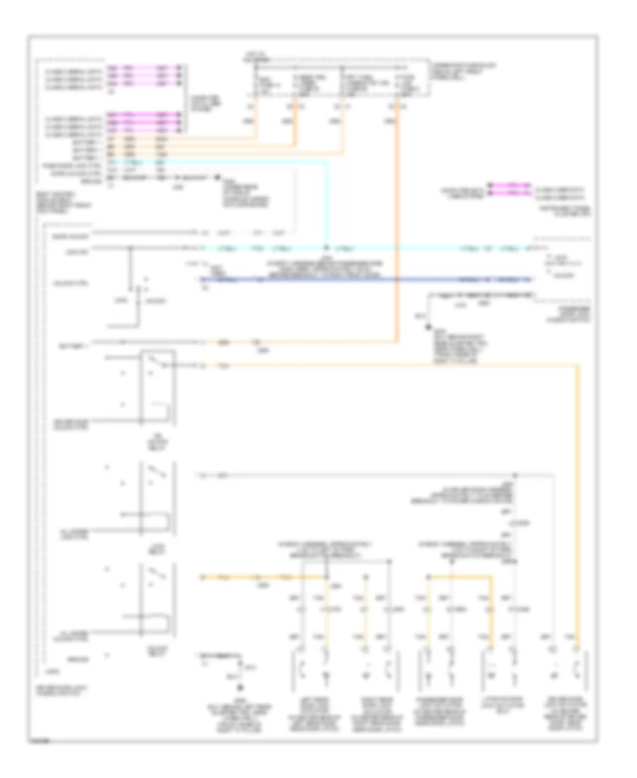 https://portal-diagnostov.com/license.html
Automotive Electricians Portal FZCO
Automotive Electricians Portal FZCO
https://portal-diagnostov.com/license.html
https://portal-diagnostov.com/license.html
Automotive Electricians Portal FZCO
Automotive Electricians Portal FZCOList of elements for Power Door Locks Wiring Diagram for Hummer H3 2010:
- (in body harness, approximately 3 cm to left of park brake switch breakout)
- (in body harness, approximately 3 cm to right of park brake switch breakout) j295
- (not used)
- A11
- A12
- A38
- A39
- A41
- A42
- A44
- A47
- All doors lock ctrl
- All doors unlock ctrl
- Battery +
- Bcm fuse 14 10a
- Body control module (bcm) (behind right front kick panel)
- Class 2 ser data
- Class 2 serial data
- Computer data lines system
- Door unlock
- Door unlock ctrl
- Dr unlock relay
- Driver door lock actuator (in center rear of driver door, near door latch)
- Driver door lock/ window switch
- Driver door unlock ctrl
- Frt turn/ hazrd/ctsy mir fuse 56 15a
- G320 (under rear of middle console carpet, on floor board)
- G340 (suv: behind right rear quarter trim, near wheelwell) (truck: base of right "c" pillar)
- G350 (suv: behind left rear quarter trim, near wheelwell) (truck: base of right "c" pillar)
- Ground
- Hot at all times
- Instrument panel cluster (ipc)
- J244 (in body harness behind passenger side dash area, approximately 25 cm before breakout to right front door)
- J294
- J315
- J320
- J514
- J529 (in driver door harness, approximately 7.5 cm before breakout to power window motor)
- Left rear door lock actuator (in center rear of left rear door, near door latch)
- Liftgate door lock actuator (suv)
- Lock
- Lock relay
- Lock sw
- Logic
- Pass door lock ctrl
- Passenger door lock actuator (in center rear of passenger door, near door latch)
- Passenger door lock/ window switch
- Pwr/ lks fuse 8 20a
- Rear trn/ hazrd fuse 20 20a
- Right rear door lock actuator (in center rear of right rear door, near door latch)
- Tan
- Underhood fuse block (above left front wheelwell)
- Unlock
- Unlock ctrl
- Unlock relay
- X450
- X500
- X600
- X700
- X800
POWER MIRRORS
Electrochromic Mirror Wiring Diagram for Hummer H3 2010
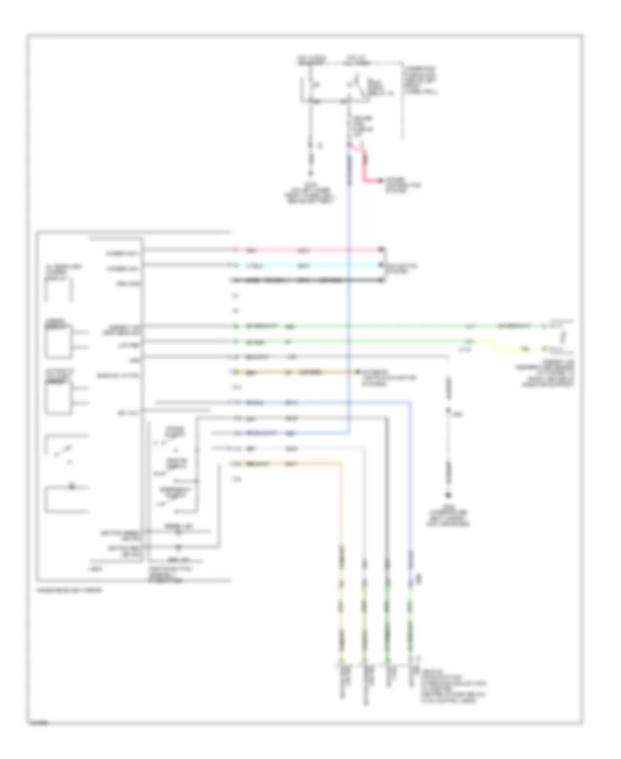 https://portal-diagnostov.com/license.html
Automotive Electricians Portal FZCO
Automotive Electricians Portal FZCO
https://portal-diagnostov.com/license.html
https://portal-diagnostov.com/license.html
Automotive Electricians Portal FZCO
Automotive Electricians Portal FZCOList of elements for Electrochromic Mirror Wiring Diagram for Hummer H3 2010:
- (or 7069)
- (or 9992)
- (w/ rear view camera) display
- Ambient air temp sens sig
- Ambient air temperature sensor (attached to front center of radiator support)
- Automatic day/night mirror
- Backup lp ctrl
- Bare
- Camera sig +
- Camera sig -
- Cruise/ misc fuse 35 10a
- Drai gnd
- Emergency switch
- Exterior lights & navigation systems
- G105 (on left inner front wheelwell, behind battery)
- G300 (under driver seat carpet, on floor board)
- Gnd
- Green led
- Hot at all times
- Hot in run or start
- Ign volt
- Inside rearview mirror
- J300
- Keypad
- Keypad ctrl
- Keypad green led sig
- Keypad red led sig
- Logic
- Low ref
- Mirror display
- Navigation system
- Onstar button assembly (if equipped)
- Onstar switch
- Phone switch
- Pnk
- Power distribution system
- Red led
- Run/ crnk relay 78
- Underhood fuse block (above left front wheelwell)
- Vehicle communication interface module (vcim) (w/ onstar) (center of dash below hvac control head)
- X1 sig
- X115
- X200
Power Mirrors Wiring Diagram for Hummer H3 2010
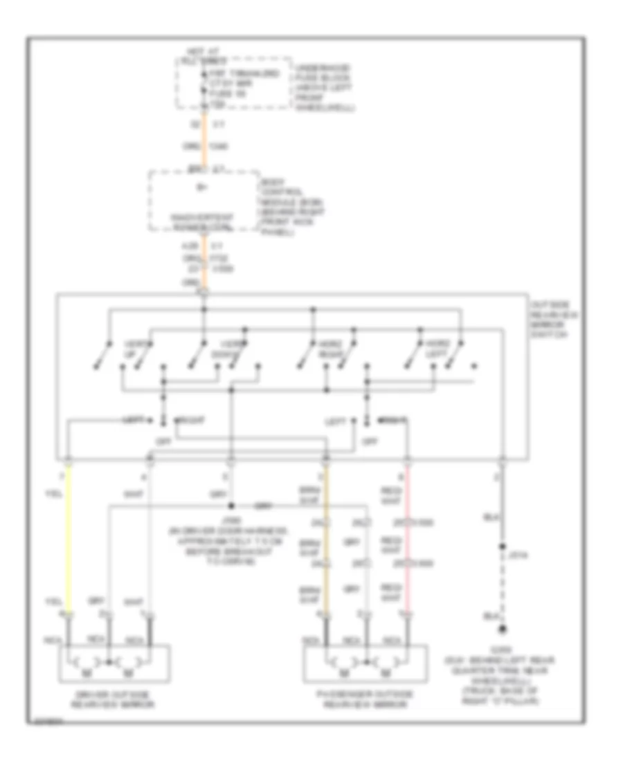 https://portal-diagnostov.com/license.html
Automotive Electricians Portal FZCO
Automotive Electricians Portal FZCO
https://portal-diagnostov.com/license.html
https://portal-diagnostov.com/license.html
Automotive Electricians Portal FZCO
Automotive Electricians Portal FZCOList of elements for Power Mirrors Wiring Diagram for Hummer H3 2010:
- A29
- Body control module (bcm) (behind right front kick panel)
- Down
- Driver outside rearview mirror
- Frt trn/hazrd ctsy mir fuse 56 15a
- G350 (suv: behind left rear quarter trim, near wheelwell) (truck: base of right "c" pillar)
- Horz left
- Horz right
- Hot at all times
- Inadvertent power ctrl
- J514
- J590 (in driver door harness, approximately 7.5 cm before breakout to osrvm)
- Left
- Nca
- Off
- Outside rearview mirror switch
- Passenger outside rearview mirror
- Right
- Underhood fuse block (above left front wheelwell)
- Vert
- Vert up
- X500
- X600
POWER SEATS
Driver Heated Seat Wiring Diagram for Hummer H3 2010
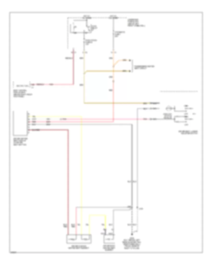 https://portal-diagnostov.com/license.html
Automotive Electricians Portal FZCO
Automotive Electricians Portal FZCO
https://portal-diagnostov.com/license.html
https://portal-diagnostov.com/license.html
Automotive Electricians Portal FZCO
Automotive Electricians Portal FZCOList of elements for Driver Heated Seat Wiring Diagram for Hummer H3 2010:
- A26
- Body control module (bcm) (behind right front kick panel)
- Driver back heated seat element
- Driver cushion heated seat element
- Driver heated seat module (in driver seat bottom)
- Driver seat lumbar adjuster switch
- G345 (suv: behind left rear quarter trim, near wheelwell) (truck: base of right "c" pillar)
- High
- High/low status ind bulb
- Hot at all times
- Htd/seats fuse 1 20a
- Hvac relay
- Ign 3 rly coil
- J306
- J322
- Low
- Nca
- Passenger's heated seat circuit
- Pnk
- Pwr htr sw fuse 53 10a
- Red
- Underhood fuse block (above left front wheelwell)
Driver Power Seat Wiring Diagram for Hummer H3 2010
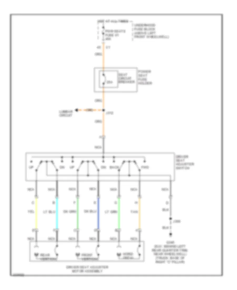 https://portal-diagnostov.com/license.html
Automotive Electricians Portal FZCO
Automotive Electricians Portal FZCO
https://portal-diagnostov.com/license.html
https://portal-diagnostov.com/license.html
Automotive Electricians Portal FZCO
Automotive Electricians Portal FZCOList of elements for Driver Power Seat Wiring Diagram for Hummer H3 2010:
- 25a
- Back
- Driver seat adjuster motor assembly
- Driver seat adjuster switch
- Front vertical
- Fwd
- G345 (suv: behind left rear quarter trim, near wheelwell) (truck: base of right "c" pillar)
- Horiz- ontal
- Hot at all times
- J306
- J312
- Lumbar circuit
- Nca
- Power seat fuse holder
- Pwr seats fuse 61 40a
- Rear vertical
- Seat circuit breaker
- Tan
- Underhood fuse block (above left front wheelwell)
Lumbar Wiring Diagram for Hummer H3 2010
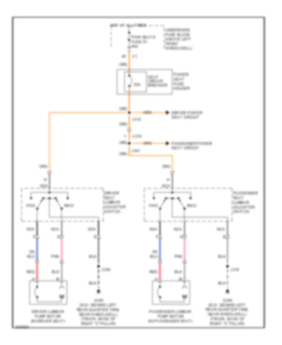 https://portal-diagnostov.com/license.html
Automotive Electricians Portal FZCO
Automotive Electricians Portal FZCO
https://portal-diagnostov.com/license.html
https://portal-diagnostov.com/license.html
Automotive Electricians Portal FZCO
Automotive Electricians Portal FZCOList of elements for Lumbar Wiring Diagram for Hummer H3 2010:
- 25a
- Driver lumbar pump motor (in driver seat)
- Driver power seat circuit
- Driver seat lumbar adjuster switch
- Fwd
- G345 (suv: behind left rear quarter trim, near wheelwell) (truck: base of right "c" pillar)
- Hot at all times
- J306
- J312
- J316
- J341
- Nca
- Passenger lumbar pump motor (in passenger seat)
- Passenger power seat circuit
- Passenger seat lumbar adjuster switch
- Pnk
- Power seat fuse holder
- Pwr seats fuse 61 40a
- Red
- Rwd
- Seat circuit breaker
- Underhood fuse block (above left front wheelwell)
- X315
Passenger Power Seat Wiring Diagram for Hummer H3 2010
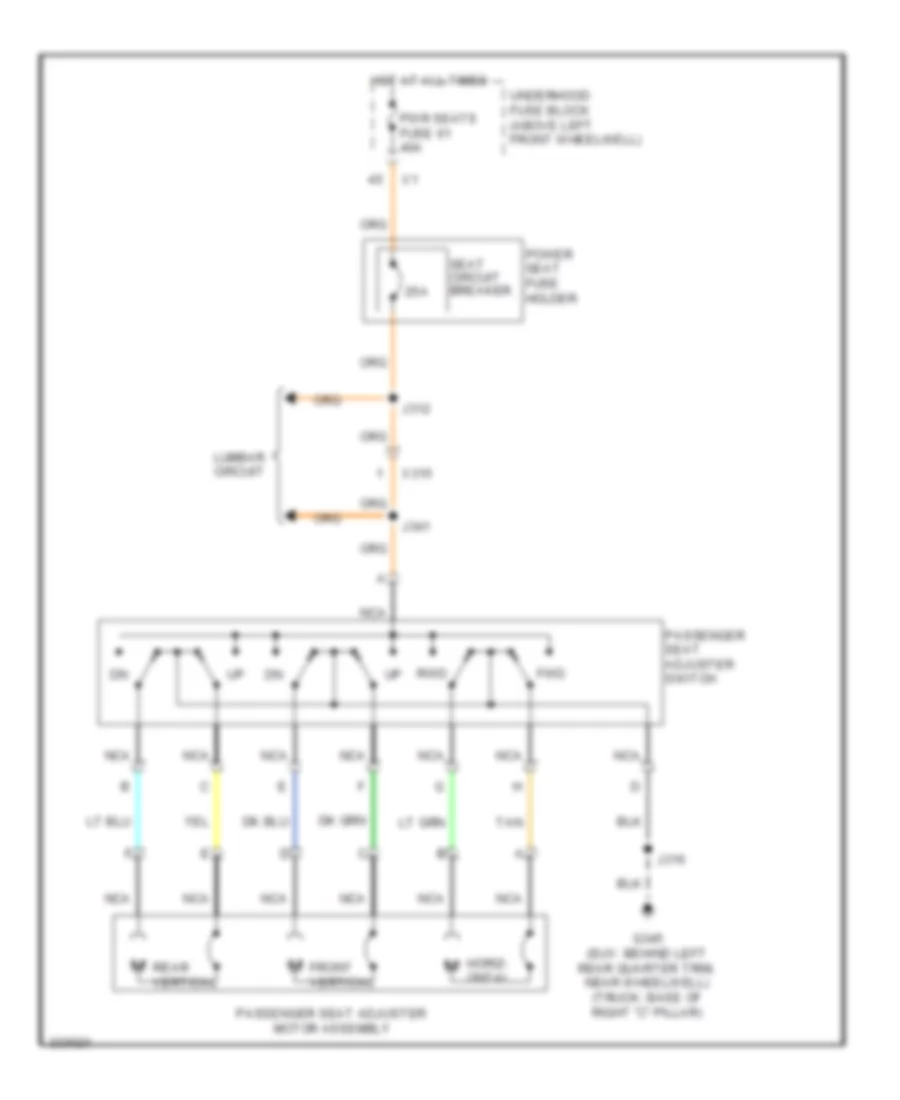 https://portal-diagnostov.com/license.html
Automotive Electricians Portal FZCO
Automotive Electricians Portal FZCO
https://portal-diagnostov.com/license.html
https://portal-diagnostov.com/license.html
Automotive Electricians Portal FZCO
Automotive Electricians Portal FZCOList of elements for Passenger Power Seat Wiring Diagram for Hummer H3 2010:
- 25a
- Front vertical
- Fwd
- G345 (suv: behind left rear quarter trim, near wheelwell) (truck: base of right "c" pillar)
- Horiz- ontal
- Hot at all times
- J312
- J316
- J341
- Lumbar circuit
- Nca
- Passenger seat adjuster motor assembly
- Passenger seat adjuster switch
- Power seat fuse holder
- Pwr seats fuse 61 40a
- Rear vertical
- Rwd
- Seat circuit breaker
- Tan
- Underhood fuse block (above left front wheelwell)
- X315
Passenger"s Heated Seat Wiring Diagram for Hummer H3 2010
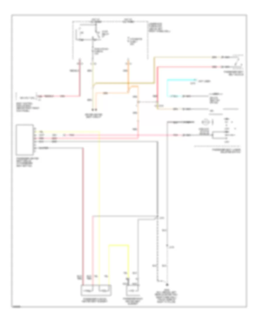 https://portal-diagnostov.com/license.html
Automotive Electricians Portal FZCO
Automotive Electricians Portal FZCO
https://portal-diagnostov.com/license.html
https://portal-diagnostov.com/license.html
Automotive Electricians Portal FZCO
Automotive Electricians Portal FZCOList of elements for Passenger"s Heated Seat Wiring Diagram for Hummer H3 2010:
- (not used)
- A26
- Body control module (bcm) (behind right front kick panel)
- C nca
- D nca
- Dr htd seat sw off sig
- Driver heated seat circuit
- G345 (suv: behind left rear quarter trim, near wheelwell) (truck: base of right "c" pillar)
- High
- High/low status ind bulb
- Hot at all times
- Htd/seats fuse 1 20a
- Hvac relay
- Ign
- Ign 3 rly coil
- J316
- J318
- Logic
- Low
- Nca
- Passenger back heated seat element
- Passenger cushion heated seat element
- Passenger heated seat module (in passenger seat bottom)
- Passenger seat belt buckle
- Passenger seat lumbar adjuster switch
- Pnk
- Pwr htr sw fuse 53 10a
- Red
- Underhood fuse block (above left front wheelwell)
- X315
POWER TOP/SUNROOF
Power Top/Sunroof Wiring Diagram for Hummer H3 2010
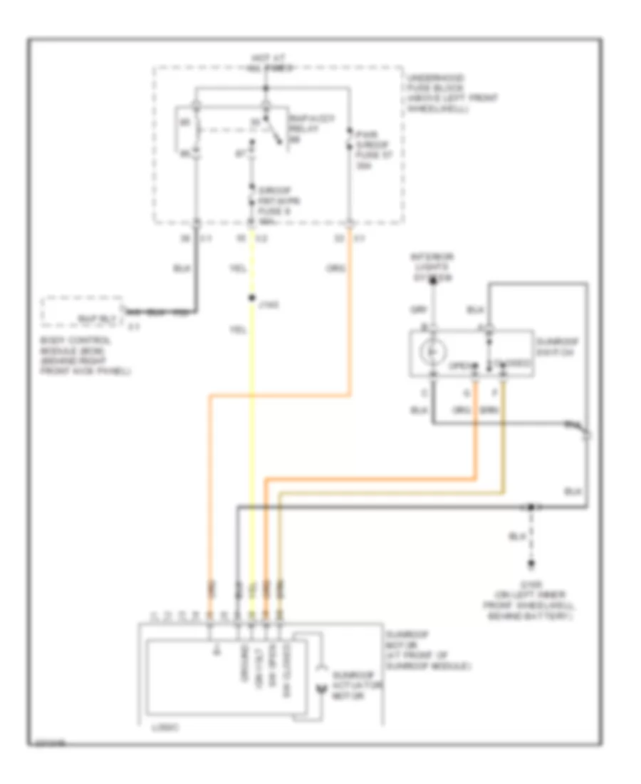 https://portal-diagnostov.com/license.html
Automotive Electricians Portal FZCO
Automotive Electricians Portal FZCO
https://portal-diagnostov.com/license.html
https://portal-diagnostov.com/license.html
Automotive Electricians Portal FZCO
Automotive Electricians Portal FZCOList of elements for Power Top/Sunroof Wiring Diagram for Hummer H3 2010:
- Body control module (bcm) (behind right front kick panel)
- Closed
- G105 (on left inner front wheelwell, behind battery)
- Ground
- Hot at all times
- Ign volt
- Interior lights system
- J143
- J210
- Logic
- Motor
- Open
- Pwr s/roof fuse 57 30a
- Rap rly
- Rap/accy relay
- S/roof frt/wpr fuse 9 10a
- Sunroof actuator m
- Sunroof motor (at front of sunroof module)
- Sunroof switch
- Sw closed
- Sw open
- Underhood fuse block (above left front wheelwell)
POWER WINDOWS
Power Windows Wiring Diagram for Hummer H3 2010
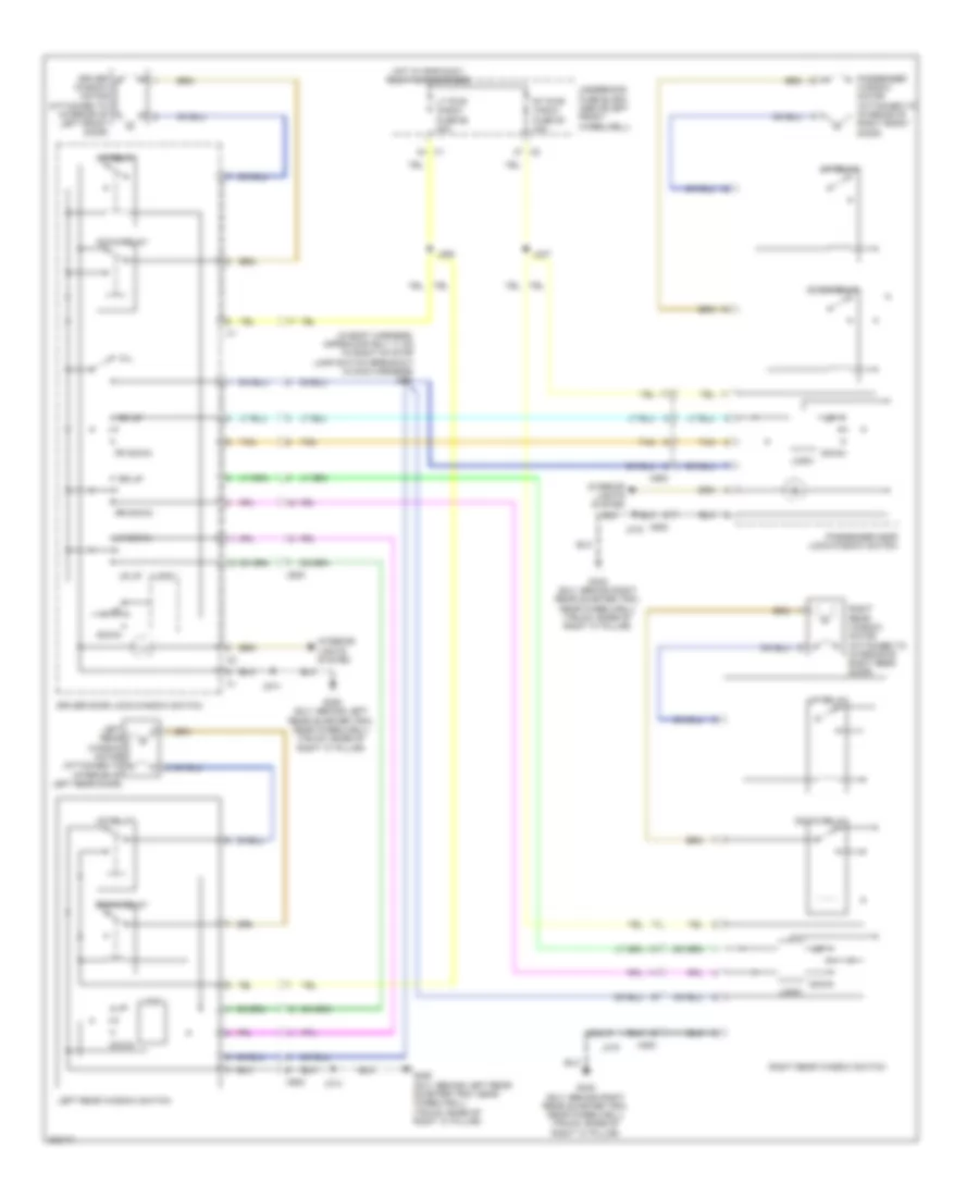 https://portal-diagnostov.com/license.html
Automotive Electricians Portal FZCO
Automotive Electricians Portal FZCO
https://portal-diagnostov.com/license.html
https://portal-diagnostov.com/license.html
Automotive Electricians Portal FZCO
Automotive Electricians Portal FZCOList of elements for Power Windows Wiring Diagram for Hummer H3 2010:
- (in body harness, approximately 11 cm to right of stop lamp switch breakout in main harness) j213
- Down
- Down relay
- Driver door lock/window switch
- Driver window motor (attached to interior of left front door)
- G340 (suv: behind right rear quarter trim, near wheelwell) (truck: base of right "c" pillar)
- G350 (suv: behind left rear quarter trim, near wheelwell) (truck: base of right "c" pillar)
- Hot w/ rap/accy relay 88 energized
- Interior lights system
- J247
- J264
- J314
- J315
- J514
- Left rear window motor (attached to interior of left rear door)
- Left rear window switch
- Logic
- Lr down
- Lr up
- Lt pwr wndw fuse 68 30a
- Passenger door lock/window switch
- Passenger window motor (attached to interior of right front door)
- Rf down
- Rf up
- Right rear window motor (attached to interior of right rear door)
- Right rear window switch
- Rr down
- Rr up
- Rt pwr wndw fuse 63 30a
- Tan
- Underhood fuse block (above left front wheelwell)
- Up relay
- W/l
- X500
- X600
- X800
RADIO
Base Radio Wiring Diagram for Hummer H3 2010
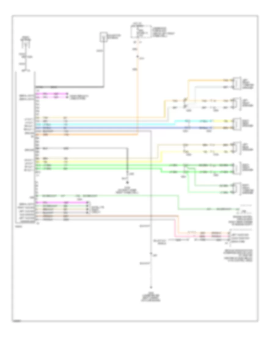 https://portal-diagnostov.com/license.html
Automotive Electricians Portal FZCO
Automotive Electricians Portal FZCO
https://portal-diagnostov.com/license.html
https://portal-diagnostov.com/license.html
Automotive Electricians Portal FZCO
Automotive Electricians Portal FZCOList of elements for Base Radio Wiring Diagram for Hummer H3 2010:
- A10
- A11
- A12
- Aud common
- Audio comm sig
- B10
- B11
- B12
- Coax
- Coax sr x220
- Common sig
- Computer data lines system
- Drain wire
- Engine control module (ecm) (right rear corner of engine compt)
- G106 (on right inner front wheelwell)
- G300 (under driver seat carpet, on floor board)
- Ground
- Hot at all times
- J205
- J214
- J251
- Left aud sig
- Left audio sig
- Left front speaker
- Left front tweeter speaker
- Left rear speaker
- Lf out +
- Lf out -
- Lr out +
- Lr out -
- Lt-gn
- Navigation antenna
- Nca
- Radio
- Radio antenna
- Rdo fuse 13 10a
- Rf out +
- Rf out -
- Right aud sig
- Right front speaker
- Right front tweeter speaker
- Right rear speaker
- Rr out +
- Rr out -
- Satellite radio circuit
- Serial data
- Tan
- Underhood fuse block (above left front wheelwell)
- Vehicle communication interface module (vcim) (w/ onstar) (center of dash below hvac control head)
- Vss
- X200
- X204
- X3 sr
- X500
- X600
- X700
- X800
Premium Radio Wiring Diagram (1 of 2) for Hummer H3 2010
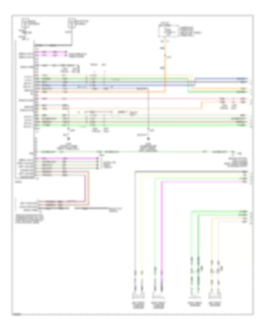 https://portal-diagnostov.com/license.html
Automotive Electricians Portal FZCO
Automotive Electricians Portal FZCO
https://portal-diagnostov.com/license.html
https://portal-diagnostov.com/license.html
Automotive Electricians Portal FZCO
Automotive Electricians Portal FZCOList of elements for Premium Radio Wiring Diagram (1 of 2) for Hummer H3 2010:
- (suv)
- (truck)
- A10
- A11
- A12
- Audio comm sig
- B10
- B11
- B12
- C10
- C11
- C12
- Coax
- Common sig
- Computer data lines system
- Drain wire
- Engine control module (ecm) (right rear corner of engine compt)
- G106 (on right inner front wheelwell)
- G300 (under driver seat carpet, on floor board)
- Ground
- Hot at all times
- J205
- J214
- J251
- Left aud sig
- Left audio sig
- Left front speaker
- Left front tweeter speaker
- Lf out +
- Lf out -
- Lr out +
- Lr out -
- Lt-gn
- Navigation antenna
- Nca
- Pnk
- Radio
- Radio antenna
- Radio mute
- Radio on sig
- Rdo fuse 13 10a
- Rf out +
- Rf out -
- Right aud sig
- Right front speaker
- Right front tweeter speaker
- Rr out +
- Rr out -
- Satellite radio circuit
- Serial data
- Suv
- Tan
- Truck
- Underhood fuse block (above left front wheelwell)
- Vehicle communication interface module (vcim) (center of dash below hvac control head)
- Vss
- X204
- X207
- X220
- X500
- X600
Premium Radio Wiring Diagram (2 of 2) for Hummer H3 2010
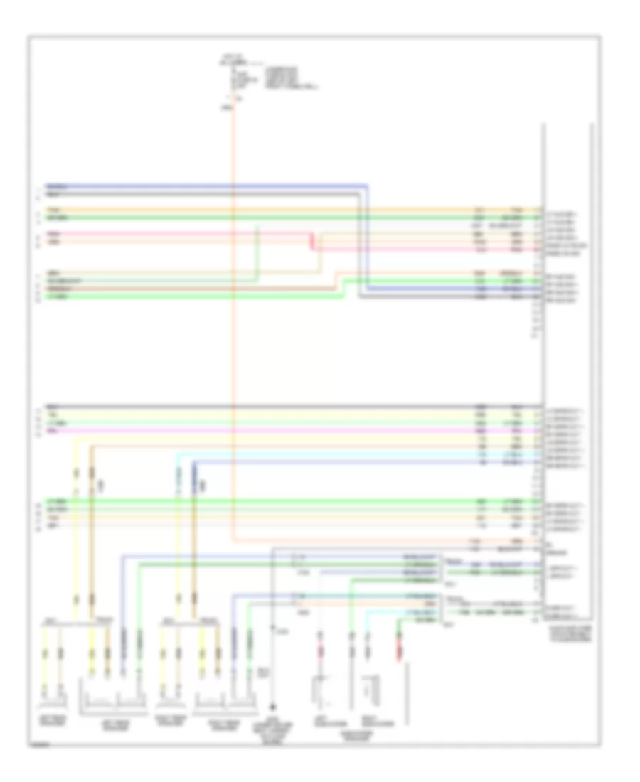 https://portal-diagnostov.com/license.html
Automotive Electricians Portal FZCO
Automotive Electricians Portal FZCO
https://portal-diagnostov.com/license.html
https://portal-diagnostov.com/license.html
Automotive Electricians Portal FZCO
Automotive Electricians Portal FZCOList of elements for Premium Radio Wiring Diagram (2 of 2) for Hummer H3 2010:
- Amp fuse 38 25a
- Audio amplifier (mounted next to subwoofer)
- G300 (under driver seat carpet, on floor board)
- Ground
- Hot at all times
- J300
- L spk out +
- L spk out -
- Left rear speaker
- Left subwoofer
- Lf aud sig +
- Lf aud sig -
- Lf spkr out +
- Lf spkr out -
- Lr aud sig +
- Lr aud sig -
- Lr spkr out +
- Lr spkr out -
- Pnk
- R spk out +
- R spk out -
- Radio mute sig
- Radio on sig
- Red
- Rf aud sig +
- Rf aud sig -
- Rf spkr out +
- Rf spkr out -
- Right rear speaker
- Right subwoofer
- Rr aud sig +
- Rr aud sig -
- Rr spkr out +
- Rr spkr out -
- Subwoofer speaker
- Suv
- Tan
- Truck
- Underhood fuse block (above left front wheelwell)
- X700
- X800
Satellite Radio Wiring Diagram for Hummer H3 2010
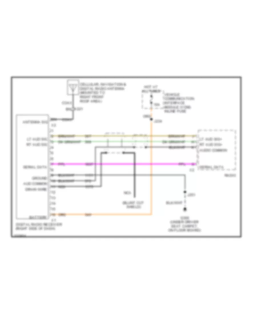 https://portal-diagnostov.com/license.html
Automotive Electricians Portal FZCO
Automotive Electricians Portal FZCO
https://portal-diagnostov.com/license.html
https://portal-diagnostov.com/license.html
Automotive Electricians Portal FZCO
Automotive Electricians Portal FZCOList of elements for Satellite Radio Wiring Diagram for Hummer H3 2010:
- 10a
- Antenna sig
- Aud common
- Audio common
- Battery
- Cellular, navigation & digital radio antenna (mounted to right front roof area)
- Coax
- Digital radio receiver (right side of dash)
- Drain wire
- G300 (under driver seat carpet, on floor board)
- Ground
- Hot at all times
- J234
- J251
- Lt aud sig
- Lt aud sig+
- Nca
- Radio
- Rt aud sig
- Rt aud sig+
- Serial data
- Vehicle communication interface module (vcim) inline fuse
- X221 bn
Video System Wiring Diagram for Hummer H3 2010
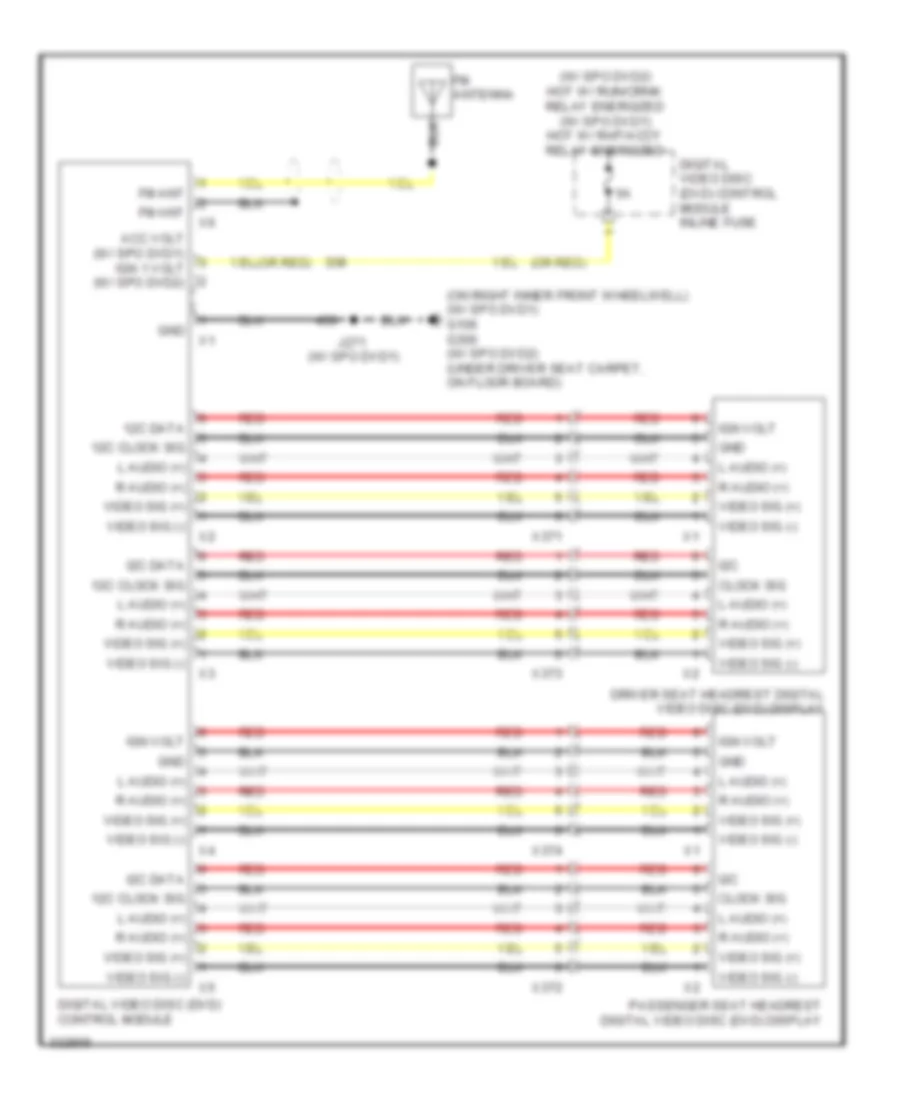 https://portal-diagnostov.com/license.html
Automotive Electricians Portal FZCO
Automotive Electricians Portal FZCO
https://portal-diagnostov.com/license.html
https://portal-diagnostov.com/license.html
Automotive Electricians Portal FZCO
Automotive Electricians Portal FZCOList of elements for Video System Wiring Diagram for Hummer H3 2010:
- (on right inner front wheelwell) (w/ spo dvd1) g106 g300 (w/ spo dvd2) (under driver seat carpet, on floor board)
- (or red)
- (w/ spo dvd1)
- (w/ spo dvd2) hot w/ run/crnk relay energized (w/ spo dvd1) hot w/ rap/accy relay energized
- 12c clock sig
- 12c data
- Acc volt (w/ spo dvd1) ign 1 volt (w/ spo dvd2)
- Clock sig
- Digital video disc (dvd) control module
- Digital video disc (dvd) control module inline fuse
- Driver seat headrest digital video disc (dvd) display
- Fm ant
- Fm antenna
- Gnd
- I2c
- I2c data
- Ign volt
- J271
- L audio (+)
- Passenger seat headrest digital video disc (dvd) display
- R audio (+)
- Red
- Video sig (+)
- Video sig (-)
- X371
- X372
- X373
- X374
SHIFT INTERLOCK
Ignition Lock Solenoid Wiring Diagram for Hummer H3 2010
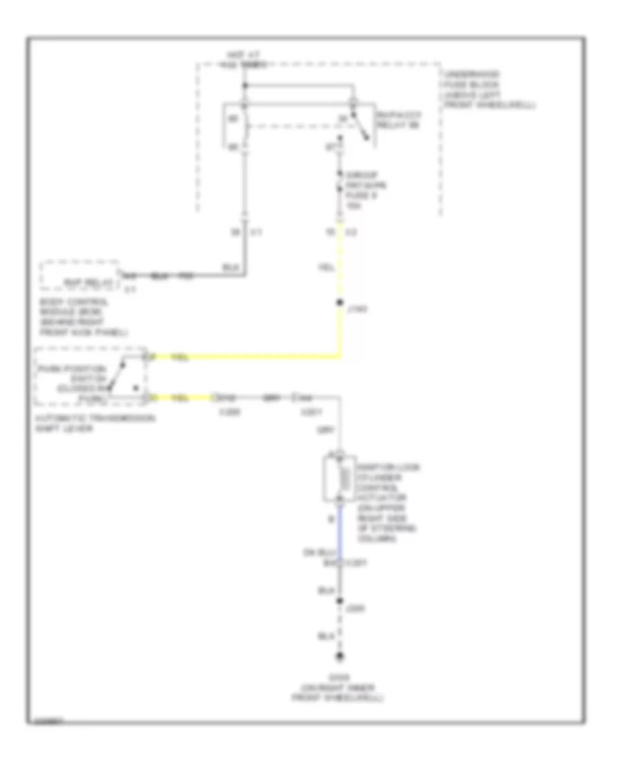 https://portal-diagnostov.com/license.html
Automotive Electricians Portal FZCO
Automotive Electricians Portal FZCO
https://portal-diagnostov.com/license.html
https://portal-diagnostov.com/license.html
Automotive Electricians Portal FZCO
Automotive Electricians Portal FZCOList of elements for Ignition Lock Solenoid Wiring Diagram for Hummer H3 2010:
- Automatic transmission shift lever
- Body control module (bcm) (behind right front kick panel)
- C12
- G106 (on right inner front wheelwell)
- Hot at all times
- Ignition lock cylinder control actuator (on upper right side of steering column)
- J143
- J205
- Park position switch (closed in park)
- Rap relay
- Rap/accy relay 88
- S/roof frt/wpr fuse 9 15a
- Underhood fuse block (above left front wheelwell)
- X200
- X201
Shift Interlock Wiring Diagram for Hummer H3 2010
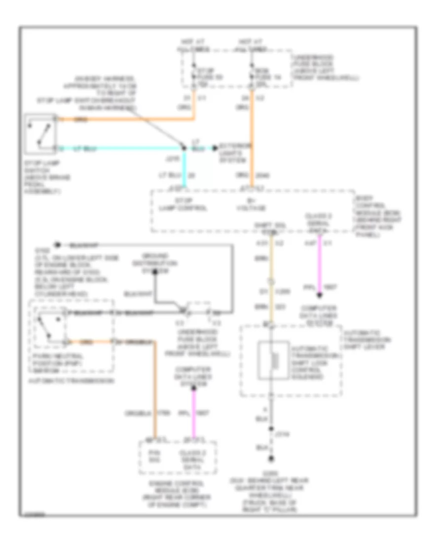 https://portal-diagnostov.com/license.html
Automotive Electricians Portal FZCO
Automotive Electricians Portal FZCO
https://portal-diagnostov.com/license.html
https://portal-diagnostov.com/license.html
Automotive Electricians Portal FZCO
Automotive Electricians Portal FZCOList of elements for Shift Interlock Wiring Diagram for Hummer H3 2010:
- (in body harness, approximately 14 cm to right of stop lamp switch breakout in main harness)
- A31 x2
- A37
- A47 x1
- Automatic transmission
- Automatic transmission shift lever
- Automatic transmission shift lock control solenoid
- B+ voltage
- Bcm fuse 14 10a
- Body control module (bcm) (behind right front kick panel)
- Class 2 serial data
- Computer data lines system
- D1 x200
- Engine control module (ecm) (right rear corner of engine compt)
- Exterior lights system
- G102 (3.7l: on lower left side of engine block, rearward of g103) (5.3l:on engine block, below left cylinder head)
- G350 (suv: behind left rear quarter trim, near wheelwell) (truck: base of right "c" pillar)
- Ground distribution system
- Hot at all times
- J215
- J314
- P/n sig
- Park/ neutral position (pnp) switch
- Shift sol ctrl
- Stop fuse 50 15a
- Stop lamp control
- Stop lamp switch (above brake pedal assembly)
- Underhood fuse block (above left front wheelwell)
- X1 a7
STARTING/CHARGING
Charging Wiring Diagram for Hummer H3 2010
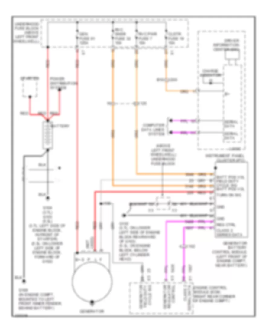 https://portal-diagnostov.com/license.html
Automotive Electricians Portal FZCO
Automotive Electricians Portal FZCO
https://portal-diagnostov.com/license.html
https://portal-diagnostov.com/license.html
Automotive Electricians Portal FZCO
Automotive Electricians Portal FZCOList of elements for Charging Wiring Diagram for Hummer H3 2010:
- (above left front wheelwell) underhood fuse block
- B10
- Batt pos vol
- Batt pos vol field duty cycle sig c
- Battery
- Charge indicator
- Class 2
- Class 2 series data
- Clstr fuse 19 10a
- Computer data lines system
- Driver information center (dic)
- Engine control module (ecm) (right rear corner of engine compt)
- Field duty
- G100 (in engine compt, mounted to left front inner fender, behind battery)
- G102 (3.7l: on lower left side of engine block rearward of g103) (5.3l: on engine block, below left cylinder head)
- G104 (3.7l) g103 (5.3l) (3.7l: left side of engine block, in front of starter) (5.3l: on lower left side of engine block, forward of g102)
- Gen fuse 91 125a
- Generator
- Generator battery control module (left front of engine compt, near battery)
- Gnd
- Instrument panel cluster (ipc)
- J136
- Logic
- Power distribution system
- Red
- Reg ctrl
- Rvc pwr fuse 7 10a
- Rvc snsr fuse 32 10a
- Serial data
- Starter
- Turn on sig
- Underhood fuse block (above left front wheelwell)
- Used) (not
- X1 serial data
- X102
- X125
- X200
- X3 control regulator
- X3 cycle sig
Starting Wiring Diagram, A/T for Hummer H3 2010
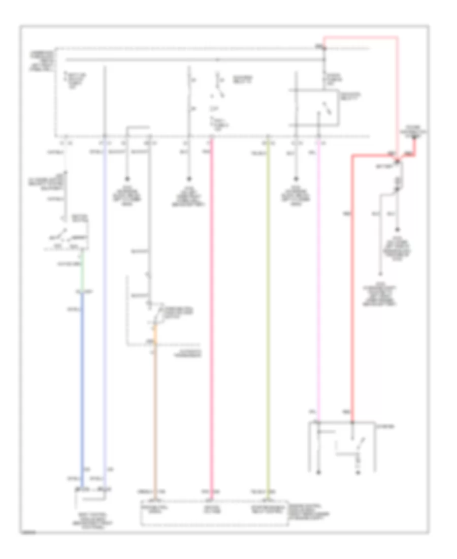 https://portal-diagnostov.com/license.html
Automotive Electricians Portal FZCO
Automotive Electricians Portal FZCO
https://portal-diagnostov.com/license.html
https://portal-diagnostov.com/license.html
Automotive Electricians Portal FZCO
Automotive Electricians Portal FZCOList of elements for Starting Wiring Diagram, A/T for Hummer H3 2010:
- Acc
- Automatic transmission
- Batt ign switch fuse 5 10a
- Battery
- Body control module (bcm) (behind right front kick panel)
- Engine control module (ecm) (right rear corner of engine compt)
- G100 (in engine compt, mounted to left front inner fender, behind battery)
- G102 (on engine block, below left cylinder head)
- G103 (on lower left side of engine block, forward of g102)
- G105 (on left inner front wheelwell, behind battery)
- Ignition switch
- Ignition voltage
- J200 (w/ immobilization security system equipment)
- Off
- Park/neutral position (pnp) switch
- Pcm 1 fuse 21 10a
- Pcm cntrl relay 77
- Pnk
- Pnp/neutral signal
- Power distribution system
- Red
- Run
- Run/crnk relay 78
- Start
- Starter
- Starter enable relay control
- Strtr fuse 85 30a
- Underhood fuse block (above left front wheelwell)
- X1 b6
- X2 b8
- X201 a2
Starting Wiring Diagram, M/T for Hummer H3 2010
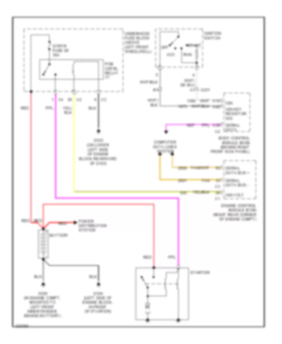 https://portal-diagnostov.com/license.html
Automotive Electricians Portal FZCO
Automotive Electricians Portal FZCO
https://portal-diagnostov.com/license.html
https://portal-diagnostov.com/license.html
Automotive Electricians Portal FZCO
Automotive Electricians Portal FZCOList of elements for Starting Wiring Diagram, M/T for Hummer H3 2010:
- A14
- A38
- A42
- Acc
- Battery
- Body control module (bcm) (behind right front kick panel)
- Computer data lines system
- Engine control module (ecm) (right rear corner of engine compt)
- G100 (in engine compt, mounted to left front inner fender, behind battery)
- G102 (on lower left side of engine block rearward of g103)
- G104 (left side of engine block, in front of starter)
- Ign
- Ign key resistor sig
- Ign volt
- Ignition switch
- Off
- Pcm cntrl relay
- Power distribution system
- Red
- Run
- Serial data
- Serial data bus +
- Serial data bus -
- Start
- Starter
- Strtr fuse 85 30a
- Tan
- Underhood fuse block (above left front wheelwell)
- X201
SUPPLEMENTAL RESTRAINTS
Supplemental Restraints Wiring Diagram (1 of 2) for Hummer H3 2010
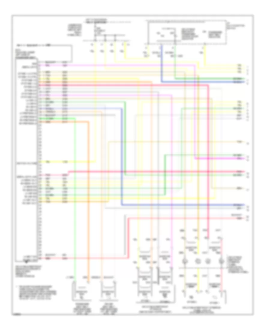 https://portal-diagnostov.com/license.html
Automotive Electricians Portal FZCO
Automotive Electricians Portal FZCO
https://portal-diagnostov.com/license.html
https://portal-diagnostov.com/license.html
Automotive Electricians Portal FZCO
Automotive Electricians Portal FZCOList of elements for Supplemental Restraints Wiring Diagram (1 of 2) for Hummer H3 2010:
- Driver seat belt pretensioner (at left inner "b" pillar)
- G310 (mounted under left side of passenger seat)
- Gnd
- Hot w/ run/crank relay energized
- I/p multi-function switch
- I/p stage 1-hi
- I/p stage 1-lo
- I/p stage 2-hi
- I/p stage 2-lo
- Ignition voltage
- Inflatable restraint i/p module (above dash compartment)
- Inflatable restraint passenger air bag on/off indicator
- Inflatable restraint sensing & diagnostic module (sdm) (beneath lower console)
- Inflatable restraint steering wheel module (in steering column)
- Inflatable restraint steering wheel module coil (mounted to steering wheel)
- J310
- Lh asf sig
- Lh asf volt
- Lh asf-hi
- Lh asf-lo
- Lh belt sw
- Lh pretens-hi
- Lh pretens-lo
- Lh sens sig
- Lh sens volt
- Nca
- Off
- Passenger seat belt indicator
- Passenger seat belt pretensioner (at right inner "b" pillar)
- Pin shorting bars engaged
- Pnk
- Red
- Rh asf sig
- Rh asf volt
- Rh asf-hi
- Rh asf-lo
- Rh belt sw
- Rh pretens-hi
- Rh pretens-lo
- Rh sens sig
- Rh sens volt
- Serial data
- Serial data link
- Shorting bar
- Sir fuse 27 10a
- Stage 1
- Stage 1-hi ctrl
- Stage 1-lo ctrl
- Stage 2
- Stage 2-hi
- Stage 2-lo
- Tan
- Underhood fuse block (above left front wheelwell)
- When module connector is disconnected from harness (shorting bars are connected between pins: 4-5, 8-9, 16-17, 18-19, 6-7, 10-11, 12-13 & 14-15)
- X200
Supplemental Restraints Wiring Diagram (2 of 2) for Hummer H3 2010
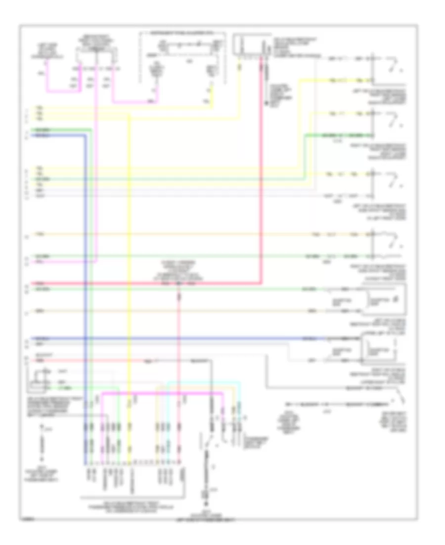 https://portal-diagnostov.com/license.html
Automotive Electricians Portal FZCO
Automotive Electricians Portal FZCO
https://portal-diagnostov.com/license.html
https://portal-diagnostov.com/license.html
Automotive Electricians Portal FZCO
Automotive Electricians Portal FZCOList of elements for Supplemental Restraints Wiring Diagram (2 of 2) for Hummer H3 2010:
- (behind right front kick panel) body control module
- (in body harness, approximately 13 cm right of breakout to g310) (w/ head curtain air bag) j323
- (left side of dash) data link connector (dlc)
- (mounted under left side of passenger seat) g310
- (upper left "b" pillar)
- A39 x2
- A42 x1
- Air bag ind
- Driver seat belt switch (part of seat belt buckle (driver))
- G310 (mounted under left side of passenger seat)
- Gnd
- Ign
- Ign volt
- Ignition volt
- Inflatable restraint front passenger presence system (pps) module (on underside of cushion)
- Inflatable restraint front passenger presence system (pps) sensor (in front passenger seat cushion)
- Inflatable restraint vehicle rollover sensor (w/ roof) (under center console)
- Instrument panel cluster (ipc)
- Ipc class 2 serial data
- J310
- Left inflatable restraint front end sensor (left lower radiator support)
- Left inflatable restraint roof rail module (w/ roof)
- Left inflatable restraint side impact sensor (sis) (w/ roof) (in left front door)
- Logic
- Low ref
- Nca
- Off ind
- On ind
- Passenger seat belt buckle
- Pnk
- Press sig
- Red
- Right inflatable restraint front end sensor (right lower radiator support)
- Right inflatable restraint roof rail module (w/ roof) (upper right "b" pillar)
- Right inflatable restraint side impact sensor (sis) (w/ roof) (in right front door)
- Seat belt ind
- Serial
- Shorting bar
- Tan
- Tension sig
- Volt ref
- X115
- X2 a38
- X315
- X500
- X600
TRANSMISSION
A/T Wiring Diagram for Hummer H3 2010
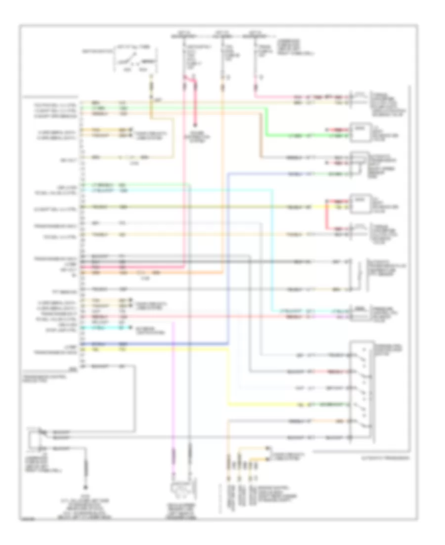 https://portal-diagnostov.com/license.html
Automotive Electricians Portal FZCO
Automotive Electricians Portal FZCO
https://portal-diagnostov.com/license.html
https://portal-diagnostov.com/license.html
Automotive Electricians Portal FZCO
Automotive Electricians Portal FZCOList of elements for A/T Wiring Diagram for Hummer H3 2010:
- 1-2 shift sol vlv ctrl
- 1-2 shift solenoid (ss) valve
- 2-3 shift sol vlv ctrl
- 2-3 shift solenoid (ss) valve
- Acc
- Air pump rly (3.7l) tcm (5.3l) fuse 17 10a
- Automatic transmission
- Automatic transmission fluid temperature (tft) sensor
- Automatic transmission input shaft speed sensor (iss)
- Computer data lines system
- Data bus + hi spd ser
- Data bus - hi spd ser
- Engine control module (ecm) (right rear corner of engine compt)
- Exterior lights system
- G102 (3.7l: on lower left side of engine block, rearward of g103) (5.3l: on engine block, below left cylinder head)
- Gnd
- Hi spd serial data +
- Hi spd serial data -
- Hot at all times
- Hot in on or start
- Ign volt
- Ignition switch
- In shaft spd sens sig
- J133
- J207
- Lo ref
- Lock
- Park/neutrol position (pnp) switch
- Pc sol valve hi ctrl
- Pc sol valve lo ctrl
- Pnk
- Power distribution system
- Pressure control (pc) solenoid valve
- Red
- Run
- Start
- Start sw sig pnp/clutch
- Stop lamp ctrl
- Tan
- Tcc pwm sol vlv ctrl
- Tcc sol vlv ctrl
- Tcm pwr fuse 26 10a
- Tft sens sig
- Torque converter clutch (tcc) pulse width modulation (pwm) solenoid valve
- Torque converter clutch (tcc) solenoid valve
- Trans fuse 34 10a
- Trans range sw p
- Trans range sw sig a
- Trans range sw sig b
- Trans range sw sig c
- Transmission control module (tcm)
- Underhood fuse block (above left front wheelwell)
- Vehicle speed sensor (vss) (left rear of transfer case)
- Vss hi sig
- Vss lo sig
- X102
- X125
Transfer Case Wiring Diagram for Hummer H3 2010
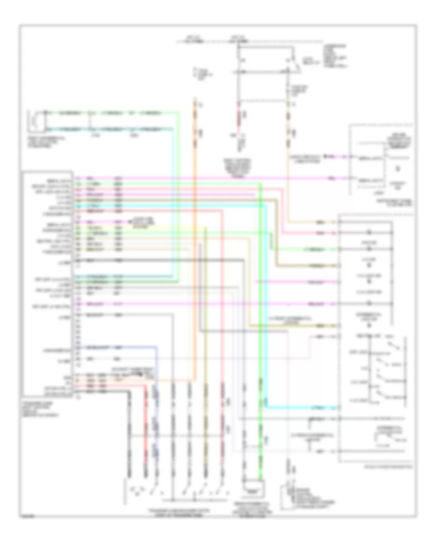 https://portal-diagnostov.com/license.html
Automotive Electricians Portal FZCO
Automotive Electricians Portal FZCO
https://portal-diagnostov.com/license.html
https://portal-diagnostov.com/license.html
Automotive Electricians Portal FZCO
Automotive Electricians Portal FZCOList of elements for Transfer Case Wiring Diagram for Hummer H3 2010:
- (on right inner front wheelwell) g106
- 4 hi
- 4 hi ind
- 4 hi lock
- 4 hi lock ind
- 4 lo ind
- 4 lo lock
- 4 lo lock ind
- 4wd ind
- 4wd lo sig
- 5 volt ref
- 5v ref
- A encoder sig
- A6 x204
- B encoder sig
- B10
- B11
- B12
- Body control module (bcm) (behind right front kick panel)
- C encoder sig
- Computer data lines system
- Ctrl ign rly
- Diff lock
- Diff lock ind ctrl
- Differential lock ind
- Differential lock switch
- Driver information center (dic) display
- Engine control module (ecm) (right rear corner of engine compt)
- Front differential lock actuator (if equipped)
- Frt diff lk hi ctrl
- Frt diff lk ind ctrl
- Frt diff lk sw sig
- Gnd
- Hot at all times
- Hvac relay 87
- I/p multi-funition switch
- Instrument panel cluster (ipc)
- Lo ref
- Locking
- Logic
- Low sig 4wd
- Motor ctrl a
- Motor ctrl b
- Nca
- Neutral ind
- Neutral ind ctrl
- P encoder sig
- Pnk
- Rear differential lock actuator (mounted to center of rear axle)
- Red
- Red e
- Rr diff lock hi ctrl
- Serial data
- Switch sig
- Tccm fuse 12 30a
- Tccm sw fuse 58 10a
- Transfer case encoder motor (part of transfer case)
- Transfer case shift control module (behind glove box)
- Underhood fuse block (above left front wheelwell)
- Up shift ind
- W/ front differential
- W/ front differential locking
- X1 a26
- X102
- X150
- X200
- X202
- X204
WARNING SYSTEMS
Warning Systems Wiring Diagram for Hummer H3 2010
 https://portal-diagnostov.com/license.html
Automotive Electricians Portal FZCO
Automotive Electricians Portal FZCO
https://portal-diagnostov.com/license.html
https://portal-diagnostov.com/license.html
Automotive Electricians Portal FZCO
Automotive Electricians Portal FZCOList of elements for Warning Systems Wiring Diagram for Hummer H3 2010:
- (in body harness, approximately 42 cm rearward of breakout to right seat belt pretensioner) (suv) j347
- A10
- A14
- A26
- A31
- A32
- A38
- A39
- A41
- A42
- A44
- Acc
- Anti-theft system
- Auto
- B7 x200
- Batt ign switch fuse 5 10a
- Battery
- Bcm fuse 14 10a
- Body control module (bcm) (behind right front kick panel)
- Brake fluid level switch (on left side of brake fluid reservoir)
- Brake ind
- Brk fluid lvl sens
- Chime
- Class 2 serial data
- Computer data lines system
- Driver door ajar switch (in lower left "b" pillar)
- Driver information center (dic) display
- Driver seat belt buckle
- Driver seat belt switch
- Electronic brake control module (ebcm) (left of master cylinder)
- G105 (on left inner front wheelwell, behind battery)
- G300 (under driver seat carpet, on floor board)
- G310 (mounted under left side of passenger seat)
- G320 (under rear of middle console carpet, on floor board)
- Head
- Headlamp switch
- Hot at all times
- Hot w/ run/crnk relay 78 energized
- I/p multi- function switch
- Ignition switch
- Ignition voltage
- Inflatable restraint sensing & diagnostic module (sdm) (beneath lower console)
- Instrument panel cluster (ipc)
- J110
- J300
- J310
- J320
- Key-in switch
- Left rear door ajar switch (in lower left "c" pillar)
- Left seat belt sw
- Left turn ind
- Lf door ajar
- Logic
- Low oil pressure ind
- Low ref
- Lr door ajar
- Lr turn sig lamp ctrl
- Nca
- Off
- Park
- Park brake sw sig
- Park brake switch (left lower side of dash)
- Passenger door ajar switch (in lower right "b" pillar)
- Passenger seat belt buckle
- Passenger seat belt ind
- Passenger seat belt switch
- Pk lmp sw sig
- Pnk
- Red
- Rf door ajar
- Right rear door ajar switch (in lower right "c" pillar)
- Right seat belt sw
- Right turn ind
- Rr door ajar
- Rr turn sig lamp ctrl
- Run
- Seat belt ind
- Seat belt ind ctrl
- Sir fuse 27 10a
- Start
- Suv
- System equipment)
- Tire pressure ind
- Truck
- Underhood fuse block (above left front wheelwell)
- X201
- X308
- X320
WIPER/WASHER
Front Wiper/Washer Wiring Diagram for Hummer H3 2010
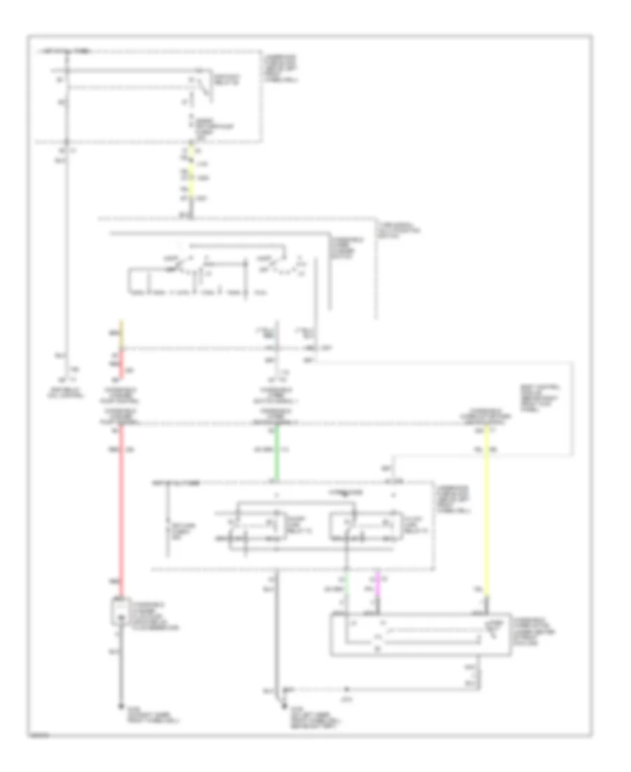 https://portal-diagnostov.com/license.html
Automotive Electricians Portal FZCO
Automotive Electricians Portal FZCO
https://portal-diagnostov.com/license.html
https://portal-diagnostov.com/license.html
Automotive Electricians Portal FZCO
Automotive Electricians Portal FZCOList of elements for Front Wiper/Washer Wiring Diagram for Hummer H3 2010:
- 87a
- A20
- Body control module (behind right front kick panel)
- Frt/wpr fuse 6 25a
- G105 (on left inner front wheelwell, behind battery)
- G106 (on right inner front wheelwell)
- Hi/low wpr relay 73
- Hot at all times
- J143
- J210
- Mist
- Nca
- Off
- On/off wpr relay 72
- Park out
- Rap relay coil control
- Rap/accy relay 88
- Red
- S/roof frt/wpr pump fuse 9 15a
- Turn signal/ multi-function switch
- Underhood fuse block (above left front wheelwell)
- Windshield washer fluid pump (mounted on fluid reservoir)
- Windshield washer pump control
- Windshield wiper motor (under center of front cowling)
- Windshield wiper motor park switch signal
- Windshield wiper switch signal 1
- Windshield wiper switch signal 2
- Windshield wiper/ washer switch
- Wiper diode
- X200
- X201
Rear Wiper/Washer Wiring Diagram for Hummer H3 2010
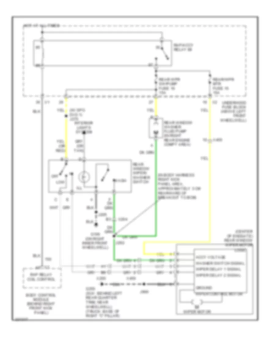 https://portal-diagnostov.com/license.html
Automotive Electricians Portal FZCO
Automotive Electricians Portal FZCO
https://portal-diagnostov.com/license.html
https://portal-diagnostov.com/license.html
Automotive Electricians Portal FZCO
Automotive Electricians Portal FZCOList of elements for Rear Wiper/Washer Wiring Diagram for Hummer H3 2010:
- (center of endgate) rear window wiper motor
- (in body harness right kick panel area, approximately 3 cm rearward of breakout to bcm)
- (w/ spo dvd 1) j270
- Accy voltage
- Body control module (behind right front kick panel)
- G106 (on right inner front wheelwell)
- G350 (suv: behind left rear quarter trim, near wheelwell) (truck: base of right "c" pillar)
- Ground
- Hot at all times
- Ill
- Interior lights system
- J205
- J292
- J900
- Logic
- Low
- Off
- Rap relay coil control
- Rap/accy relay 88
- Rear window washer fluid pump (in right rear engine compt area)
- Rear window wiper/ washer switch
- Rear wpr sw/pump fuse 16 15a
- Rear/wpr mtr fuse 15 15a
- Underhood fuse block (above left front wheelwell)
- Wash
- Washer switch signal
- Wiper control motor
- Wiper delay 1 signal
- Wiper delay 2 signal
- Wiper motor
- X200
- X204
- X450

 Čeština
 Dansk
Dansk Deutsch
 Ελληνικά
 English
 English
 Español
 Suomi
Suomi Français
 Français
 עברית
עברית Hrvatski
 Magyar
 Italiano
 한국어
한국어 Nederlands
 Polski
 Português
 Português
 Română
 Русский
 Slovenčina
 Slovenščina
 Svenska
 Türkçe
 中文 (中国)
