AIR CONDITIONING
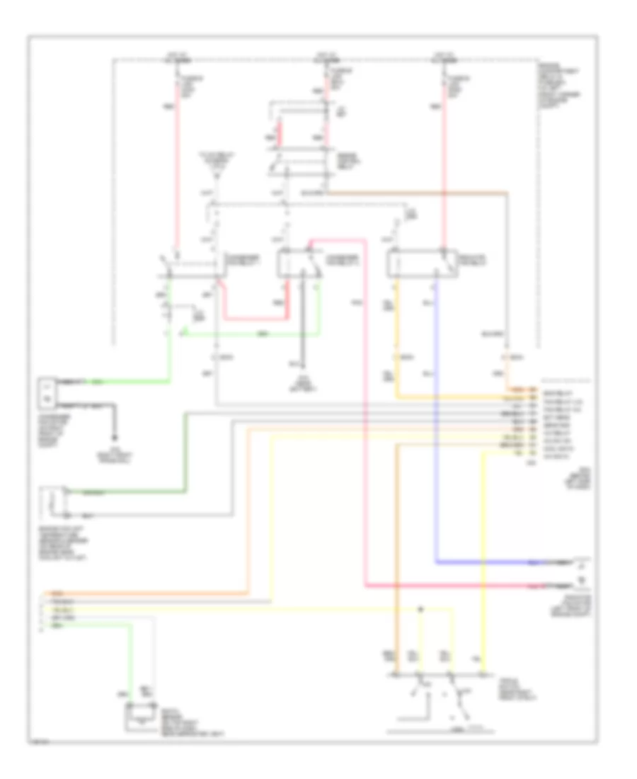
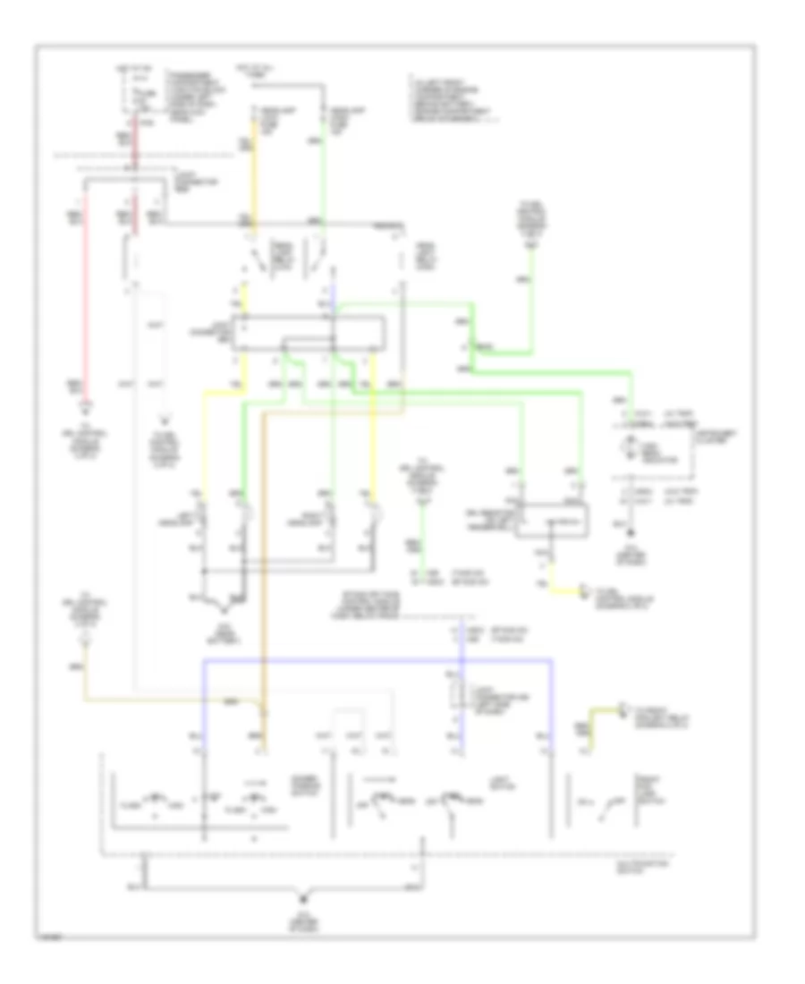
Automatic A/C Wiring Diagram (1 of 2) for Hyundai Elantra GT 2002
 https://portal-diagnostov.com/license.html
Automotive Electricians Portal FZCO
Automotive Electricians Portal FZCO
https://portal-diagnostov.com/license.html
https://portal-diagnostov.com/license.html
Automotive Electricians Portal FZCO
Automotive Electricians Portal FZCO
List of elements for Automatic A/C Wiring Diagram (1 of 2) for Hyundai Elantra GT 2002:
- (below right side of dash) blower relay
- (center of dash) g11
- A/c compressor
- A/c control module (below center of dash)
- A/c output
- A/c relay
- A/c select
- Amb temp sens
- Ambient temperature sensor (behind center of front bumper)
- Aqs sensor
- Aqs sensor (behind center of front bumper)
- Blower motor (under right side of dash)
- Blr feed back
- Cool
- Def
- Defogger sw
- Defogger system
- Ec03
- Engine compartment relay & fuse box (in left front corner of engine compt)
- Evaporator temperature sensor (behind lower left center of dash)
- Feed back sig
- Fre
- Fuse 10a
- Fuse 15a
- Fusible link (blower) 30a
- G11 (center of dash)
- G15 (near battery)
- Ground
- Hi blwr cntrl
- High blower relay (below right side of dash)
- Horn & a/c fuse 15a
- Hot at all times
- Hot at on
- Humidity sensor
- Humidity sensor (on center of rear package tray)
- I/p-b
- I/p-g
- I/p-h
- I/p-j
- Ill+
- Ill-
- In-car sens in
- In-car sens out
- Intake actuator (behind upper right side of dash)
- Interior lights system
- J/c e56
- J/c m33 (left side of dash)
- J/c m36 (left side of dash)
- M19-1
- M19-2
- Memory power
- Mode actuator (behind left center of dash)
- Nca
- On input
- Passenger compartment junction block (under left side of dash)
- Photo sens +
- Pnk
- Power transistor (under right side of dash)
- Pwr trans
- Rec
- Red
- Sensor ground
- Sensor signal
- Temperature
- Temperature actuator (behind lower left center of dash)
- To j/c 58 (diagram 2 of 2)
- Vent
- Warm
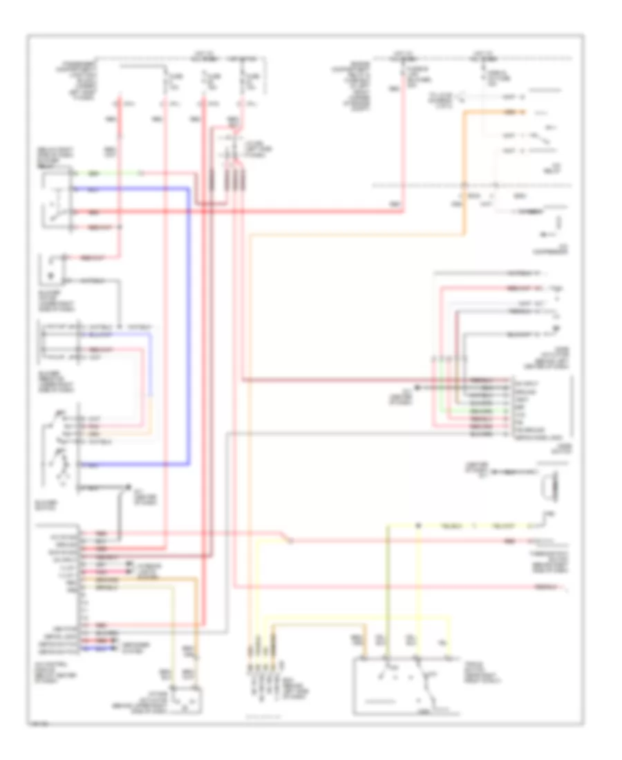
Automatic A/C Wiring Diagram (2 of 2) for Hyundai Elantra GT 2002
 https://portal-diagnostov.com/license.html
Automotive Electricians Portal FZCO
Automotive Electricians Portal FZCO
https://portal-diagnostov.com/license.html
https://portal-diagnostov.com/license.html
Automotive Electricians Portal FZCO
Automotive Electricians Portal FZCOList of elements for Automatic A/C Wiring Diagram (2 of 2) for Hyundai Elantra GT 2002:
- A/c relay
- A/c sig in
- A/c sw on
- C83
- Condenser fan motor (on right front of engine compt)
- Condenser fan relay 1
- Condenser fan relay 2
- Cool sig in
- Ec03
- Ec04
- Ecm (behind left side of dash)
- Ect sens
- Eng relay
- Engine compartment relay & fuse box (in left front corner of engine compt)
- Engine control relay
- Engine coolant temperature sensor & sender (on rear of engine near coolant outlet)
- Fan relay (hi)
- Fan relay (lo)
- Fusible link (con) 20a
- Fusible link (ecu) 20a
- Fusible link (rad) 20a
- G15 (near battery)
- G16 (right front frame rail)
- High
- Hot at all times
- J/c e57
- J/c e58
- J/c e59
- Low
- Mid
- Nca
- Photo sensor (on top right side of dash, near defroster vent)
- Pnk
- Radiator fan motor (left front of engine compt)
- Radiator fan relay
- Red
- Sens gnd
- To a/c relay (diagram 1 of 2)
- Triple switch (near right front strut)
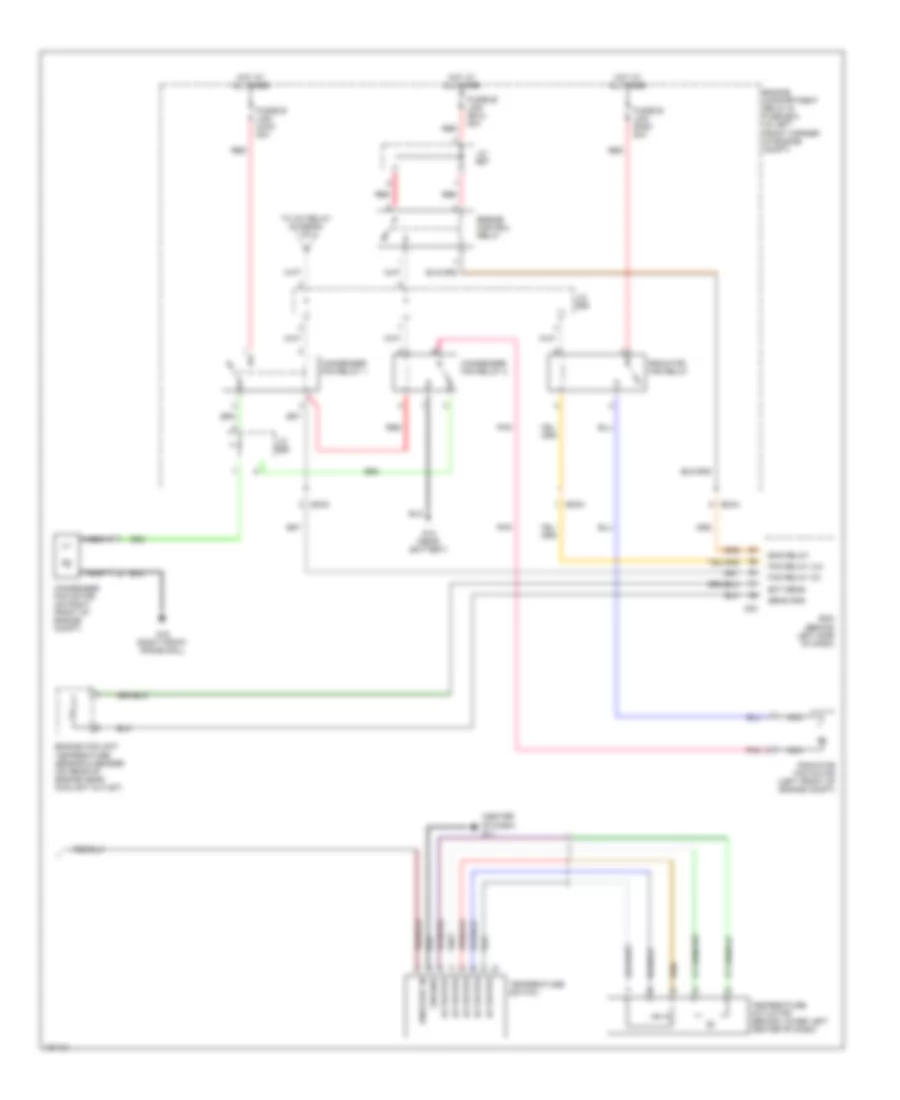
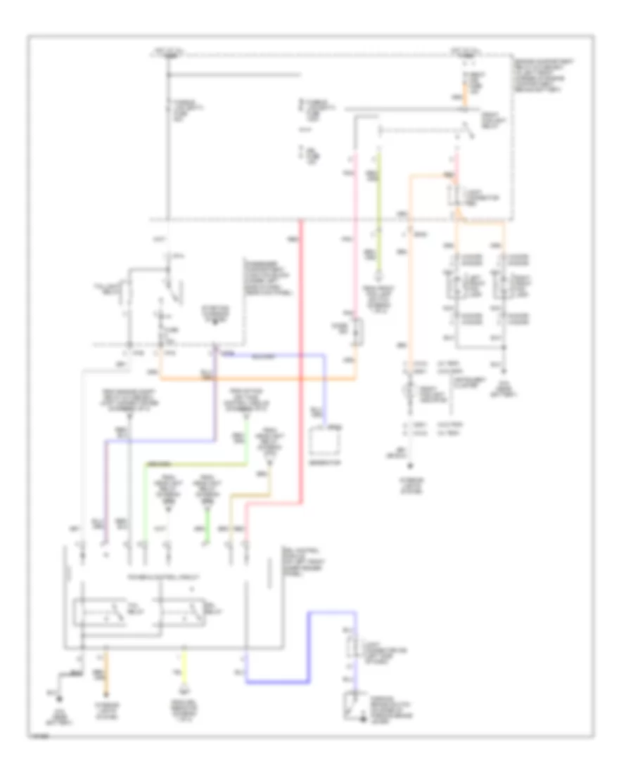
Manual A/C Wiring Diagram (1 of 2) for Hyundai Elantra GT 2002
 https://portal-diagnostov.com/license.html
Automotive Electricians Portal FZCO
Automotive Electricians Portal FZCO
https://portal-diagnostov.com/license.html
https://portal-diagnostov.com/license.html
Automotive Electricians Portal FZCO
Automotive Electricians Portal FZCOList of elements for Manual A/C Wiring Diagram (1 of 2) for Hyundai Elantra GT 2002:
- (below right side of dash) blower relay
- (center of dash) g11
- A/c compressor
- A/c control module (below center of dash)
- A/c on sig
- A/c relay
- A/c rly
- A/c sig
- A/c sw on
- Blower motor (under right side of dash)
- Blower resistor (under right side of dash)
- Blower switch
- Blr on sig
- C fan sig
- C83
- Def
- Defog logic
- Defog mode logic
- Defog switch
- Defogger system
- Ec03
- Ecm (behind left side of dash)
- Engine compartment relay & fuse box (in left front corner of engine compt)
- F/b
- F/b ground
- Fre
- Fuse 10a
- Fuse 15a
- Fusible link (blower) 30a
- G11 (center of dash)
- Ground
- High
- Horn & a/c fuse 15a
- Hot at all times
- Hot at on
- I/p-g
- I/p-h
- I/p-j
- Iii
- Iiii
- Illum +
- Illum -
- Intake actuator (behind upper right side of dash)
- Interior lights system
- J/c m36 (left side if dash)
- Low
- Mem pwr
- Mid
- Mode actuator (behind left center of dash)
- Mode switch
- Nca
- Off
- On input
- Passenger compartment junction block (under left side if dash)
- Pnk
- Rec
- Red
- Thermistor
- Thermostatic switch (behind right side of dash)
- To j/c 58 (diagram 2 of 2)
- Triple switch (near right front strut)
- Vcc
- Vent
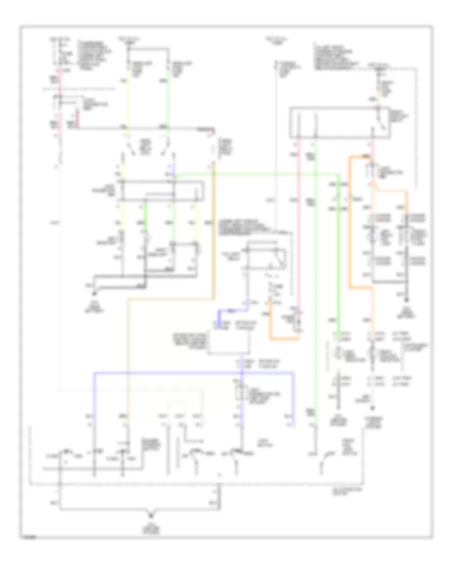
Manual A/C Wiring Diagram (2 of 2) for Hyundai Elantra GT 2002
 https://portal-diagnostov.com/license.html
Automotive Electricians Portal FZCO
Automotive Electricians Portal FZCO
https://portal-diagnostov.com/license.html
https://portal-diagnostov.com/license.html
Automotive Electricians Portal FZCO
Automotive Electricians Portal FZCOList of elements for Manual A/C Wiring Diagram (2 of 2) for Hyundai Elantra GT 2002:
- (center of dash) g11
- Actuator
- C83
- Condenser fan motor (on right front of engine compt)
- Condenser fan relay 1
- Condenser fan relay 2
- Ec03
- Ec04
- Ecm (behind left side of dash)
- Ect sens
- Eng relay
- Engine compartment relay & fuse box (in left front corner of engine compt)
- Engine control relay
- Engine coolant temperature sensor & sender (on rear of engine near coolant outlet)
- Fan relay (hi)
- Fan relay (lo)
- Fusible link (con) 20a
- Fusible link (ecu) 20a
- Fusible link (rad) 20a
- G15 (near battery)
- G16 (right front frame rail)
- Ground
- Hot at all times
- J/c e57
- J/c e58
- J/c e59
- Nca
- On/start in
- Pnk
- Radiator fan motor (left front of engine compt)
- Radiator fan relay
- Red
- Sens gnd
- Temperature actuator (behind lower left center of dash)
- Temperature switch
- To a/c relay (diagram 1 of 2)
ANTI-LOCK BRAKES
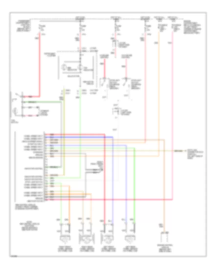
Anti-lock Brake Wiring Diagrams for Hyundai Elantra GT 2002
 https://portal-diagnostov.com/license.html
Automotive Electricians Portal FZCO
Automotive Electricians Portal FZCO
https://portal-diagnostov.com/license.html
https://portal-diagnostov.com/license.html
Automotive Electricians Portal FZCO
Automotive Electricians Portal FZCOList of elements for Anti-lock Brake Wiring Diagrams for Hyundai Elantra GT 2002:
- (right front frame rail) g17
- Abs active module
- Abs control module (in right front corner of engine compartment)
- Abs indicator
- Abs pump motor
- Abs solenoids
- C83
- Connector (dlc) (partial) (on left side of dash)
- Data link
- Diagnosis
- Engine compartment relay & fuse box (in left front corner of engine compartment, behind battery)
- Engine control module (behind left side of dash)
- Fuse 10a
- Fuse 15a
- Fusible link (abs 1) 30a
- Fusible link (abs 2) 30a
- Ground
- Hot at all times
- Hot in on or start
- I/p-b
- I/p-h
- I/p-j
- Indicator control
- Instrument cluster
- Interior lights system
- J/c c91 (left side of dash)
- J/c m36 (right side of dash)
- Left front wheel sensor (on wheel hub)
- Left rear wheel sensor (on wheel hub)
- M09-3
- M10-1
- M10-2
- Nca
- Note: abs control module contains: abs solenoids & abs pump motor
- Passenger compartment junction block (behind left side of dash)
- Pnk
- Red
- Right front wheel sensor (on wheel hub)
- Right rear wheel sensor (on wheel hub)
- Solid state
- Start/on input
- Stop lamp switch
- Stoplight switch (on brake pedal bracket)
- Tcs indicator
- Tcs switch
- Vehicle speed signal
- W/cruise control
- W/o cruise control
- W/o trip
- W/trip
- Wheel speed input
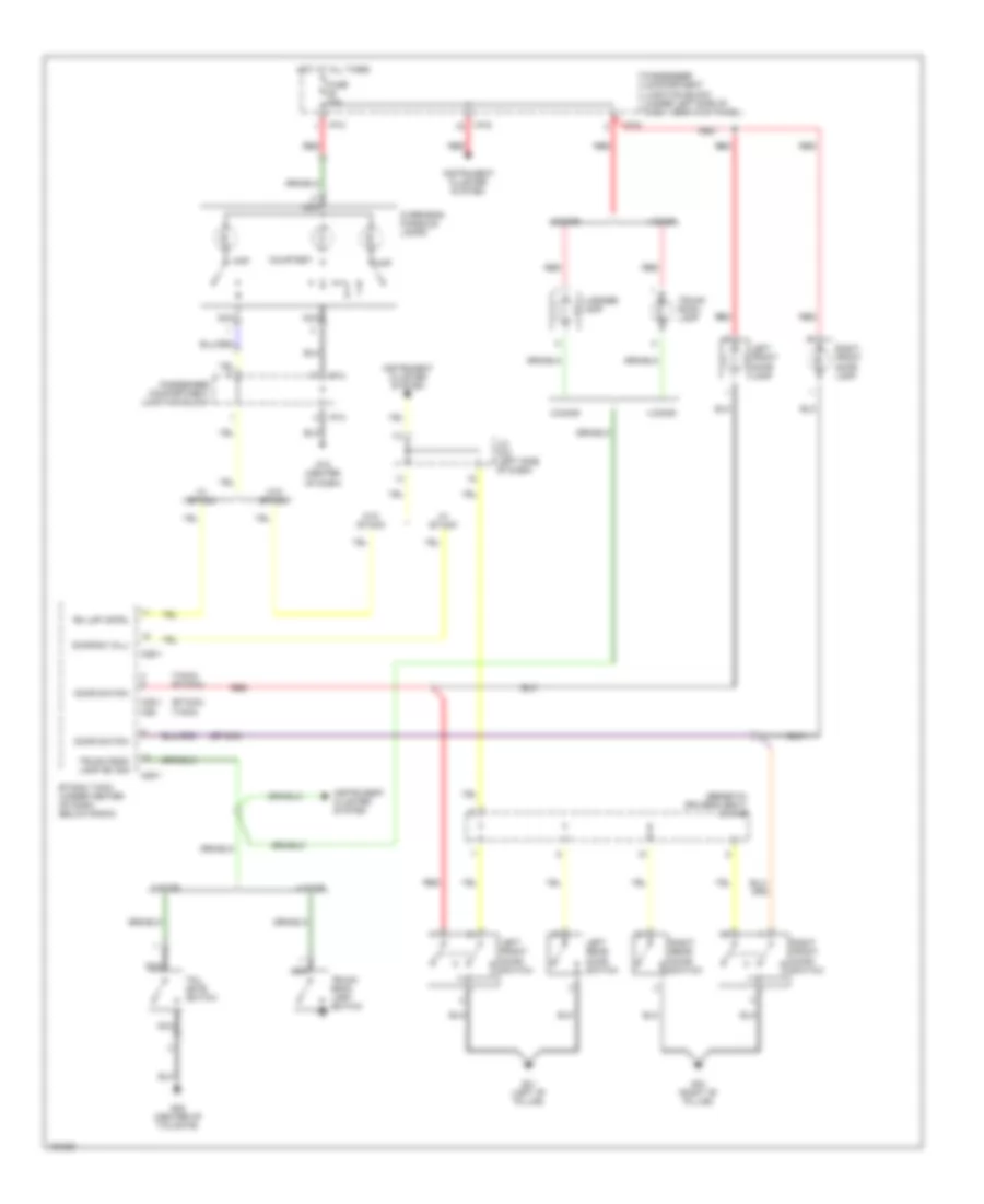
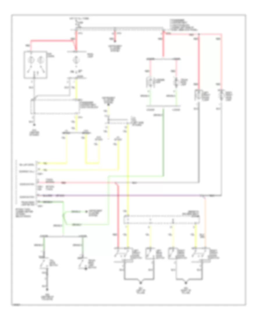
ANTI-THEFT
Anti-theft Wiring Diagram for Hyundai Elantra GT 2002
 https://portal-diagnostov.com/license.html
Automotive Electricians Portal FZCO
Automotive Electricians Portal FZCO
https://portal-diagnostov.com/license.html
https://portal-diagnostov.com/license.html
Automotive Electricians Portal FZCO
Automotive Electricians Portal FZCOList of elements for Anti-theft Wiring Diagram for Hyundai Elantra GT 2002:
- 4-door
- 5-door
- B/alarm rly cntrl
- Burglar alarm relay (below left side of dash, beside passenger compt relay block)
- Dl rly cntrl (lk)
- Dl rly cntrl (unlk)
- Door locks system
- Door sw (all)
- Ec04
- Engine compartment relay & fuse box
- Etacs control module (under center of dash, below radio)
- Exterior lights system
- Fuse 10a
- Fuse 15a
- G05 (left "c" pillar)
- G11 (center of dash)
- G28 (center of tailgate)
- Ground
- Hazard rly cntrl
- Hood switch
- Hood switch (right front corner of engine compt)
- Hot at all times
- Hot at on
- Hot at on or start
- I/p-g
- I/p-h
- I/p-j
- Interior lights system
- J/c e62
- J/c m36 (left side of dash)
- Lf door sw
- Lf dr lk/unlk in
- M25-1
- M25-2
- M25-3
- Memory pwr
- Nca
- On input
- On/start in
- Passenger compartment junction block
- Pnk
- Red
- Rf door sw
- Rf dr lk/unlk in
- Room lamp cntrl
- Siren (left rear engine compt)
- Siren cntrl
- Starting system
- Tail rly on cntrl
- Tailgate switch (left side of tailgate)
- Trnk lk/unlk in
- Trnk sw in
- Trnk unlk in
- Trunk room lamp switch (right side of trunk)
- Trunk unlock switch (on trunk lid)
BODY COMPUTER
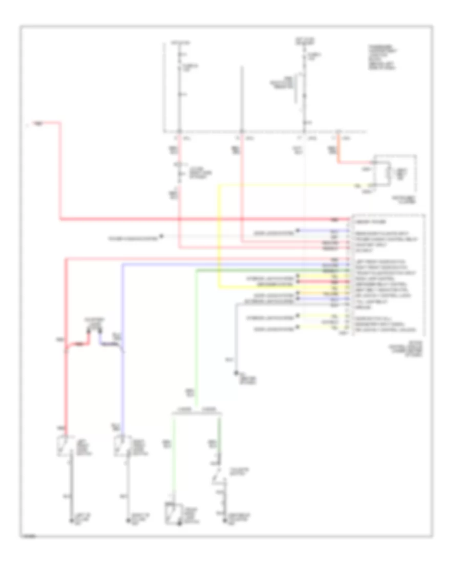
Body Computer Wiring Diagrams, with ETACM (1 of 2) for Hyundai Elantra GT 2002
 https://portal-diagnostov.com/license.html
Automotive Electricians Portal FZCO
Automotive Electricians Portal FZCO
https://portal-diagnostov.com/license.html
https://portal-diagnostov.com/license.html
Automotive Electricians Portal FZCO
Automotive Electricians Portal FZCOList of elements for Body Computer Wiring Diagrams, with ETACM (1 of 2) for Hyundai Elantra GT 2002:
- (center of dash) g12
- (left "b" pillar) g01
- (left "c" pillar) g05
- Anti-theft system
- B/alarm relay control
- Chime bell (behind left side of dash)
- Chime bell control
- Code save
- Defogger switch on input
- Defogger system
- Door locks system
- Door warning switch input
- Etacs control module (under center of dash)
- Exterior lamps system
- Exterior lights system
- Fuse 25 15a
- Hazard relay control
- Headlamps system
- Hood switch
- Hood switch (at right front corner of engine compartment)
- Hot at all times
- I/p-g
- Ignition key illumination & door warning switch
- Illum
- Instrument cluster system
- Int
- Int (time)
- J/c m33 (right side of dash)
- Key hole illum control
- Left front lock/unlock input
- M25-2
- M25-3
- Multipurpose check connector (below left side of dash)
- Nca
- Passenger compartment junction block (behind left side of dash)
- Pnk
- Red
- Right front lock/unlock input
- Seat belt switch
- Seat belt switch (in driver's seat belt buckle)
- Siren control
- Starting/charging system
- Tail lamp relay
- Tail lamp relay on control
- Trunk unlock switch (4 door)
- Trunk/tailgate unlock switch
- Washer input
- Wiper motor relay control
- Wiper/ washer system
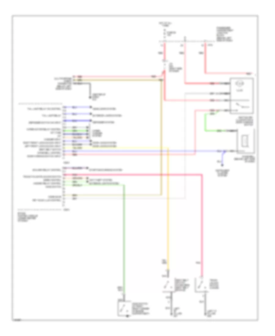
Body Computer Wiring Diagrams, with ETACM (2 of 2) for Hyundai Elantra GT 2002
 https://portal-diagnostov.com/license.html
Automotive Electricians Portal FZCO
Automotive Electricians Portal FZCO
https://portal-diagnostov.com/license.html
https://portal-diagnostov.com/license.html
Automotive Electricians Portal FZCO
Automotive Electricians Portal FZCOList of elements for Body Computer Wiring Diagrams, with ETACM (2 of 2) for Hyundai Elantra GT 2002:
- (center of tailgate) g28
- (left "b" pillar) g01
- (right "b" pillar) g03
- 4 door
- 5 door
- Courtesy lamps system
- Defogger relay control
- Defogger system
- Door locks system
- Door switch (all)
- Dr lock rly control (lock)
- Dr lock rly control (unlock)
- Engine rpm input signal
- Etacs control module (under center of dash)
- Exterior lights system
- Fuse 2 10a
- Fuse 24 10a
- G11 (center of dash)
- Ground
- Hot in on
- Hot in on or start
- I/p-g
- I/p-h
- I/p-j
- Instrument cluster
- Interior lights system
- J/c m36 (right side of dash)
- Left front door switch
- M09-1
- M09-3
- M25-1
- Memory power
- Nca
- On input
- On/start input
- Passenger compartment junction block (behind left side of dash)
- Power window control relay
- Power windows system
- Pre- excitation resistor
- Rear door/tailgate input
- Red
- Right front door switch
- Room lamp control
- Seat belt ind
- Seat belt indicator ctrl
- Tail lamp relay
- Tailgate switch
- Trunk room lamp switch
- Trunk/tailgate switch input
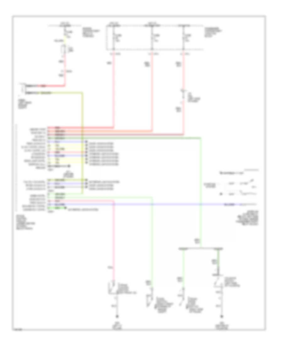
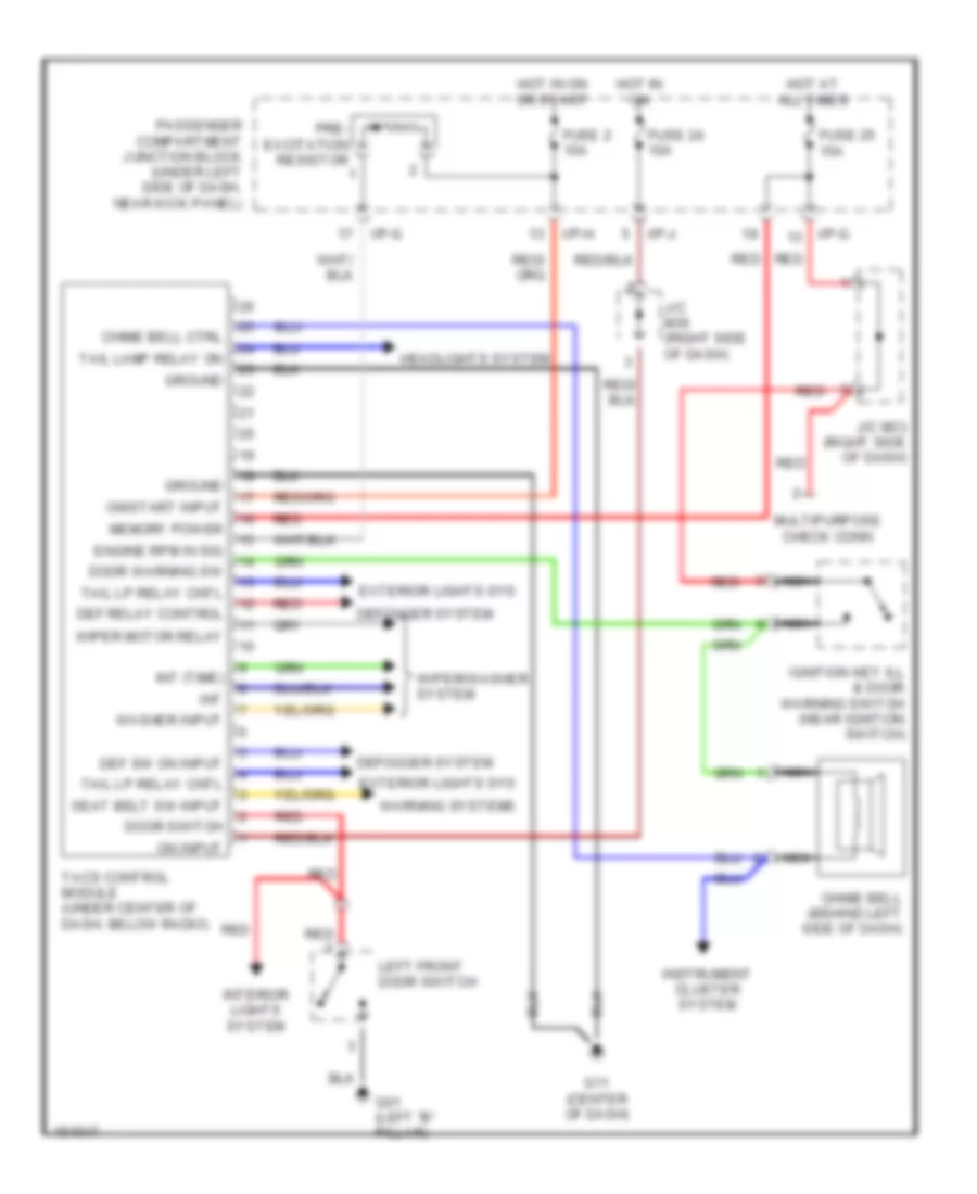
Body Computer Wiring Diagrams, without ETACM for Hyundai Elantra GT 2002
 https://portal-diagnostov.com/license.html
Automotive Electricians Portal FZCO
Automotive Electricians Portal FZCO
https://portal-diagnostov.com/license.html
https://portal-diagnostov.com/license.html
Automotive Electricians Portal FZCO
Automotive Electricians Portal FZCOList of elements for Body Computer Wiring Diagrams, without ETACM for Hyundai Elantra GT 2002:
- Chime bell (behind left side of dash)
- Chime bell ctrl
- Def relay control
- Def sw on input
- Defogger system
- Door switch
- Door warning sw
- Engine rpm in sig
- Exterior lights sys
- Fuse 2 10a
- Fuse 24 10a
- Fuse 25 15a
- G01 (left "b" pillar)
- G11 (center of dash)
- Ground
- Headlights system
- Hot at all times
- Hot in on
- Hot in on or start
- I/p-g
- I/p-h
- I/p-j
- Ignition key ill & door warning switch (near ignition switch)
- Instrument cluster system
- Int
- Int (time)
- Interior lights system
- J/c m33 (right side of dash)
- J/c m36 (right side of dash)
- Left front door switch
- Memory power
- Multipurpose check conn
- Nca
- On input
- On/start input
- Passenger compartment junction block (under left side of dash, near kick panel)
- Pre- excitation resistor
- Red
- Seat belt sw input
- Tacs control module (under center of dash, below radio)
- Tail lamp relay on
- Tail lp relay cntl
- Warning systems
- Washer input
- Wiper motor relay
- Wiper/washer system
COMPUTER DATA LINES
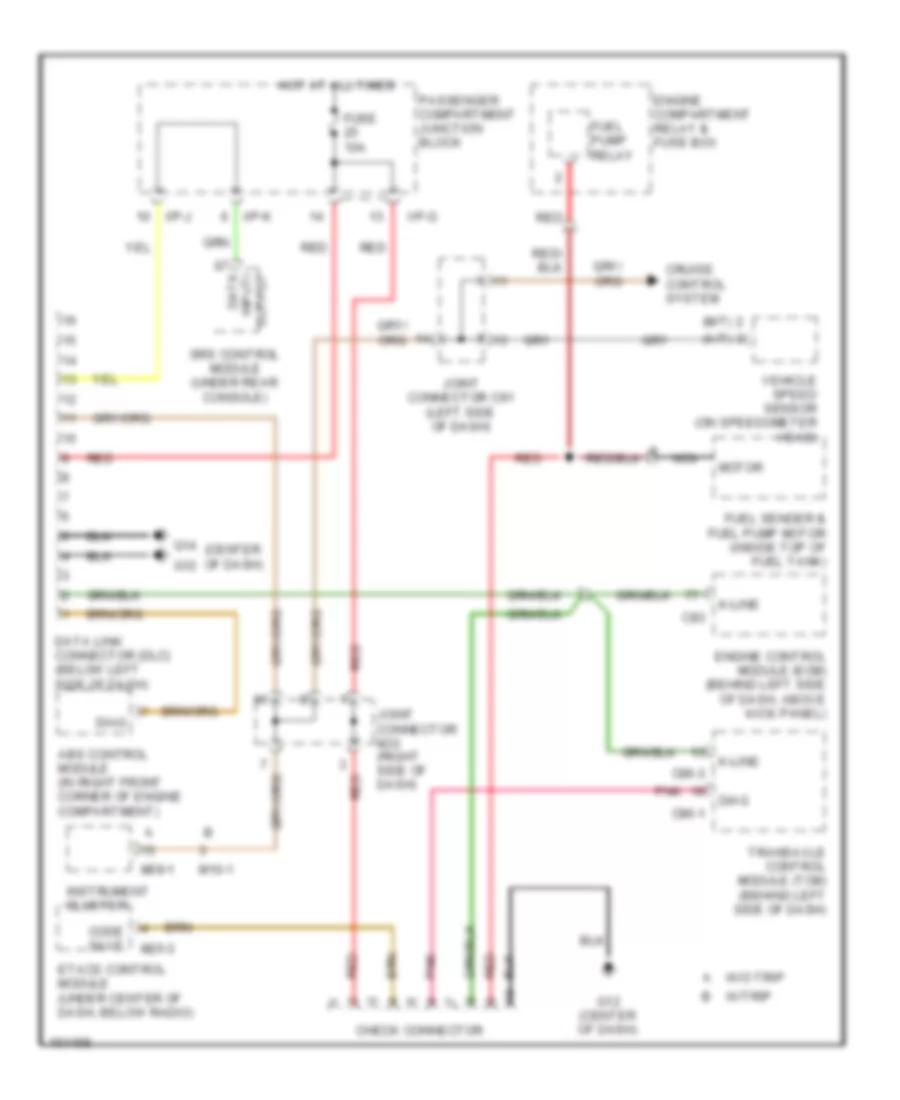
Computer Data Lines for Hyundai Elantra GT 2002
 https://portal-diagnostov.com/license.html
Automotive Electricians Portal FZCO
Automotive Electricians Portal FZCO
https://portal-diagnostov.com/license.html
https://portal-diagnostov.com/license.html
Automotive Electricians Portal FZCO
Automotive Electricians Portal FZCOList of elements for Computer Data Lines for Hyundai Elantra GT 2002:
- (a/t)
- (center of dash)
- (m/t)
- Abs control module (in right front corner of engine compartment)
- C83
- C86-1
- C86-3
- Check connector
- Code save
- Cruise control system
- Data input/ output
- Data link connector (dlc) (below left side of dash)
- Diag
- Engine compartment relay & fuse box
- Engine control module (ecm) (behind left side of dash, above kick panel)
- Etacs control module (under center of dash, below radio)
- Fuel pump relay
- Fuel sender & fuel pump motor (inside top of fuel tank)
- Fuse 10a
- G12
- G12 (center of dash)
- G14
- Hot at all times
- I/p-g
- I/p-j
- I/p-k
- Instrument cluster
- Joint connector c91 (left side of dash)
- Joint connector m33 (right side of dash)
- K-line
- M09-1
- M10-1
- M25-3
- Motor
- Nca
- Passenger compartment junction block
- Pnk
- Red
- Srs control module (under rear console)
- Transaxle control module (tcm) (behind left side of dash)
- Vehicle speed sensor (on speedometer head)
- W/o trip
- W/trip
COOLING FAN
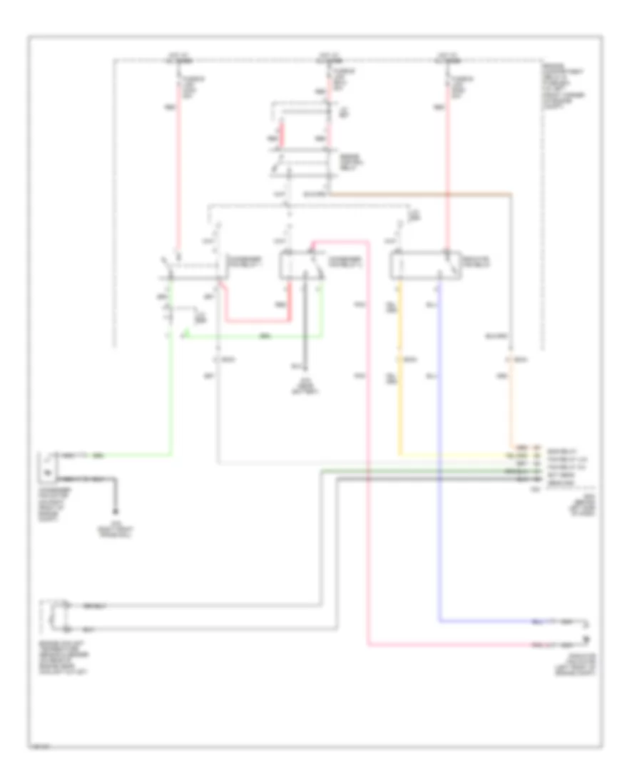
Cooling Fan Wiring Diagram for Hyundai Elantra GT 2002
 https://portal-diagnostov.com/license.html
Automotive Electricians Portal FZCO
Automotive Electricians Portal FZCO
https://portal-diagnostov.com/license.html
https://portal-diagnostov.com/license.html
Automotive Electricians Portal FZCO
Automotive Electricians Portal FZCOList of elements for Cooling Fan Wiring Diagram for Hyundai Elantra GT 2002:
- C83
- Condenser fan motor (on right front of engine compt)
- Condenser fan relay 1
- Condenser fan relay 2
- Ec03
- Ec04
- Ecm (behind left side of dash)
- Ect sens
- Eng relay
- Engine compartment relay & fuse box (in left front corner of engine compt)
- Engine control relay
- Engine coolant temperature sensor & sender (on rear of engine near coolant outlet)
- Fan relay (hi)
- Fan relay (lo)
- Fusible link (con) 20a
- Fusible link (ecu) 20a
- Fusible link (rad) 20a
- G15 (near battery)
- G16 (right front frame rail)
- Hot at all times
- J/c e57
- J/c e58
- J/c e59
- Nca
- Pnk
- Radiator fan motor (left front of engine compt)
- Radiator fan relay
- Red
- Sens gnd
CRUISE CONTROL
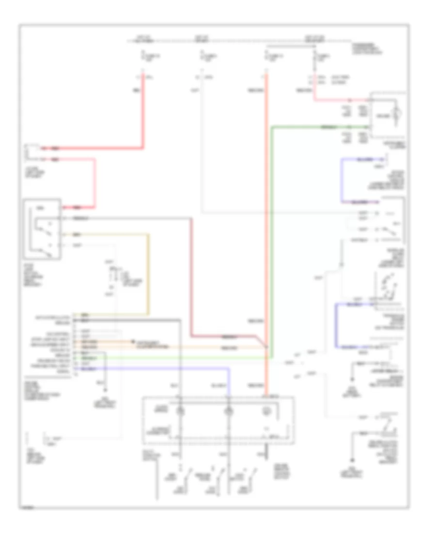
Cruise Control Wiring Diagram for Hyundai Elantra GT 2002
 https://portal-diagnostov.com/license.html
Automotive Electricians Portal FZCO
Automotive Electricians Portal FZCO
https://portal-diagnostov.com/license.html
https://portal-diagnostov.com/license.html
Automotive Electricians Portal FZCO
Automotive Electricians Portal FZCOList of elements for Cruise Control Wiring Diagram for Hyundai Elantra GT 2002:
- (w/o trip)
- (w/trip)
- A/t
- Actuator clutch
- Burglar alarm relay (under left side of dash)
- C86-1
- Clock spring
- Cruise
- Cruise clutch pedal position switch (on clutch pedal bracket)
- Cruise control module (in center of dash under radio)
- Cruise remote control switch
- Cruise sw ind on
- Ec03
- Engine compartment relay & fuse box
- Etacs control module (under center of dash below radio)
- Fuse 10 10a
- Fuse 16 15a
- Fuse 2 10a
- Fuse 8 10a
- G15 (near battery)
- G23 (left front frame rail)
- Ground
- Hot at all times
- Hot at on or start
- Hot at start
- I/p-g
- I/p-h
- I/p-j
- Instrument cluster
- Instrument cluster system
- J/c c91 (left side of dash)
- J/c m36 (left side of dash)
- M/t
- M01-3
- M01-4
- M09-1 (w/o trip)
- M10-1 (w/ trip)
- M10-2 (w/ trip)
- M25-3
- Main sw in
- Main switch
- Multi- function switch
- Nca
- O/d control
- Ohms
- Park/neutral input
- Passenger compartment junction block
- Red
- Resume/ accel
- Set/ coast
- Signal
- Slipring connector
- Start relay
- Stop lamp sw input
- Stop lamp switch (on brake pedal bracket)
- Tcm (behind left side of dash)
- Transaxle range switch (on transaxle)
- Vehicle speed input
DEFOGGERS
Defogger Wiring Diagram for Hyundai Elantra GT 2002
 https://portal-diagnostov.com/license.html
Automotive Electricians Portal FZCO
Automotive Electricians Portal FZCO
https://portal-diagnostov.com/license.html
https://portal-diagnostov.com/license.html
Automotive Electricians Portal FZCO
Automotive Electricians Portal FZCOList of elements for Defogger Wiring Diagram for Hyundai Elantra GT 2002:
- (auto a/c)
- (manual a/c)
- (manual a/c) (auto a/c)
- 4 door
- 5 door
- A/c control module
- Defogger
- Defogger relay
- Defogger switch
- Electronic time & alarm control module (eatcm) (behind center of dash)
- Fuse 10a
- Fuse 17 10a
- Fuse 30a
- G01 (left "b" pillar)
- G03 (right "b" pillar)
- G10 (left "c" pillar)
- G11 (center of dash)
- G28 (left "c" pillar)
- G29 (left "c" pillar)
- Glass antenna
- Hot at all times
- Hot at on or start
- I/p-d
- I/p-f
- I/p-g
- I/p-h
- Indicator
- Left outside mirror motor & defogger
- M25-1
- M25-2
- Mirror defogger
- Nca
- Off
- On/start in
- Passenger compartment junction block
- Pre- excitation resistor
- Rear
- Red
- Right outside mirror motor & defogger
- Rly cntrl
- Rpm sig
- Sw input
- W/glass antenna
- W/o glass antenna
- Window
ENGINE PERFORMANCE
2.0L
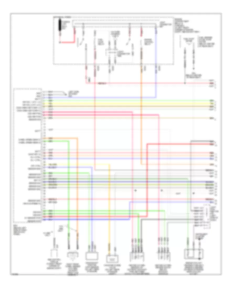
2.0L, Engine Performance Wiring Diagrams (1 of 3) for Hyundai Elantra GT 2002
 https://portal-diagnostov.com/license.html
Automotive Electricians Portal FZCO
Automotive Electricians Portal FZCO
https://portal-diagnostov.com/license.html
https://portal-diagnostov.com/license.html
Automotive Electricians Portal FZCO
Automotive Electricians Portal FZCOList of elements for 2.0L, Engine Performance Wiring Diagrams (1 of 3) for Hyundai Elantra GT 2002:
- (left side of dash) g22
- 5v sensor pwr
- Abs control module (in right front corner of engine compt)
- Batt
- Canister purge valve (on left rear of engine compt)
- Comm area network hi
- Comm area network lo
- Cpv ctrl
- Crankshaft position (ckp) sensor (on left rear of engine)
- E37
- Ec03
- Ec04
- Ecm (behind left side of dash, above kick panel)
- Ect in
- Emo2
- Engine compartment relay & fuse box (in left front corner of engine compt, behind battery)
- Engine control relay
- Engine coolant temperature (ect) sensor & sender (on rear of engine, near coolant outlet)
- Fuel pump motor
- Fuel pump relay
- Fuel sender & fuel pump motor (below center of rear seat)
- Fusible link (ecu) 20a
- G04 (below center of rear seat)
- Gnd
- Heated oxygen sensor (down) (below exhaust manifold)
- Heated oxygen sensor (up) (on front exhaust pipe, between catalytic converters)
- Hot at all times
- Ign coil 1 (cyl 1,4)
- Ign coil 2 (cyl 2,3)
- Inj 1 ctrl
- Inj 4 ctrl
- Inj fuse (diagram 2 of 3)
- Instrument cluster system
- Joint con- nector c91 (left side of dash)
- Joint connector e57
- Joint connector e58
- Nca
- O2s heating
- O2s sig
- On/start in
- Pnk
- Red
- Right front wheel sensor (w/o abs) (on right front hub assembly)
- Sensor gnd
- Sensor pwr
- Sensor sig
- Vehicle speed in
- W/ abs only
- W/o abs only
- Wheel speed sens in
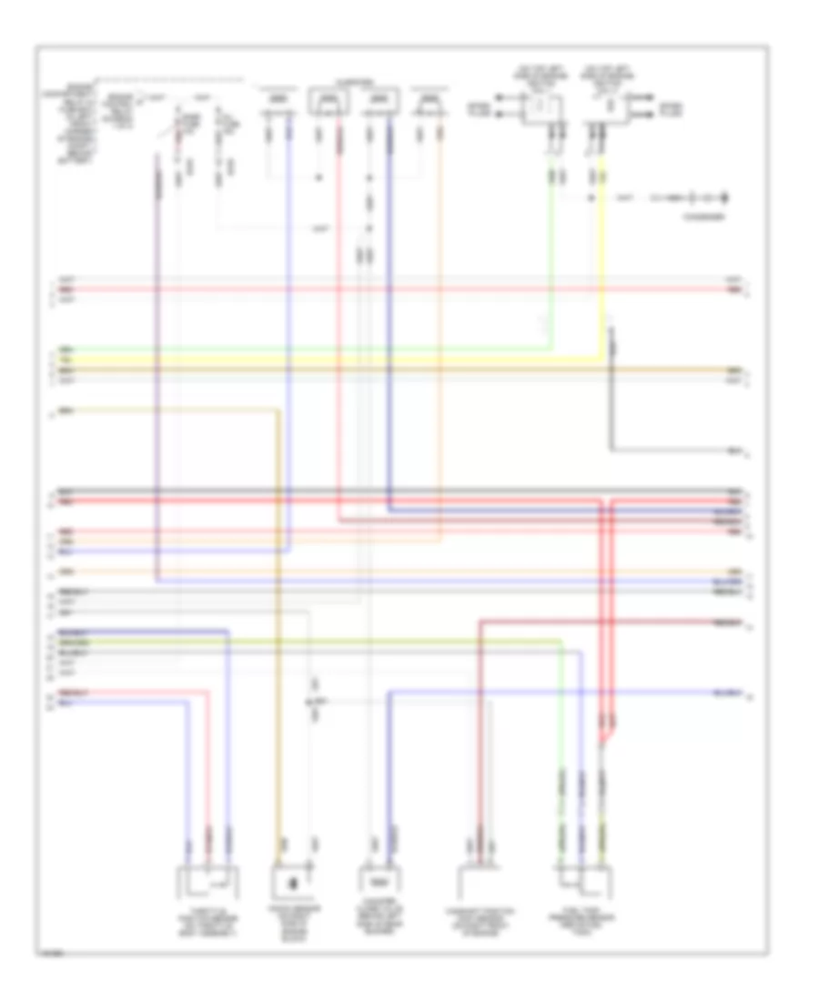
2.0L, Engine Performance Wiring Diagrams (2 of 3) for Hyundai Elantra GT 2002
 https://portal-diagnostov.com/license.html
Automotive Electricians Portal FZCO
Automotive Electricians Portal FZCO
https://portal-diagnostov.com/license.html
https://portal-diagnostov.com/license.html
Automotive Electricians Portal FZCO
Automotive Electricians Portal FZCOList of elements for 2.0L, Engine Performance Wiring Diagrams (2 of 3) for Hyundai Elantra GT 2002:
- (on top left side of engine) ignition coil 1
- (on top left side of engine) ignition coil 2
- Camshaft position (cmp) sensor (on right front of engine)
- Canister close valve (behind left side of rear bumper)
- Condenser
- Ec03
- Engine a control relay (diagram 1 of 3)
- Engine compartment relay & fuse box (in left front corner of engine compt, behind battery)
- Fuel tank pressure sensor (above fuel tank)
- Inj fuse 15a
- Injectors
- Knock sensor (on right side of engine block)
- Nca
- Pnk
- Red
- Snsr fuse 10a
- Spark plugs
- Throttle position sensor (on throttle body assembly)
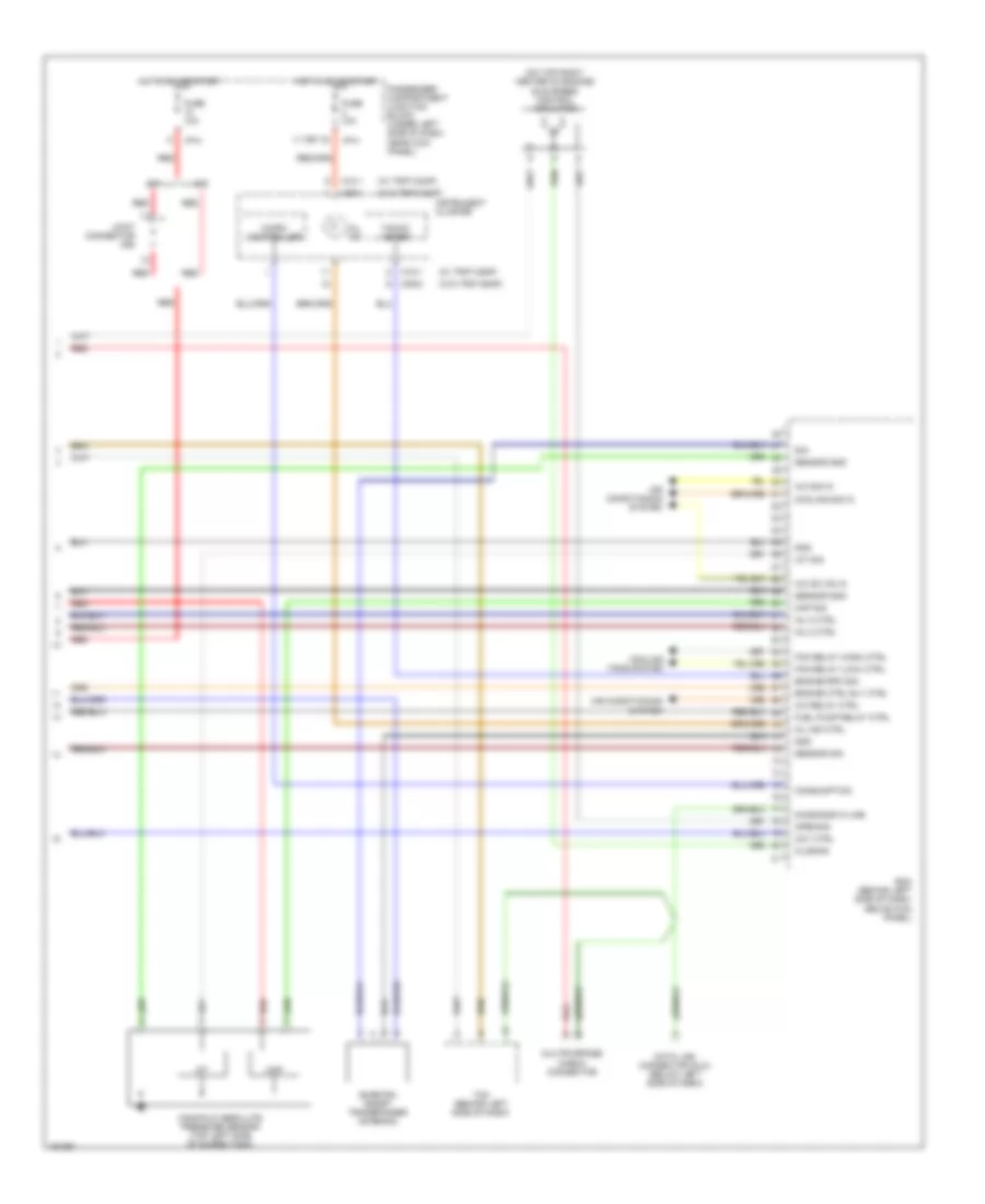
2.0L, Engine Performance Wiring Diagrams (3 of 3) for Hyundai Elantra GT 2002
 https://portal-diagnostov.com/license.html
Automotive Electricians Portal FZCO
Automotive Electricians Portal FZCO
https://portal-diagnostov.com/license.html
https://portal-diagnostov.com/license.html
Automotive Electricians Portal FZCO
Automotive Electricians Portal FZCOList of elements for 2.0L, Engine Performance Wiring Diagrams (3 of 3) for Hyundai Elantra GT 2002:
- (on top right center of engine) idle speed control actuator
- (w/ trip comp)
- (w/o trip comp)
- 11 (or 12)
- A/c relay ctrl
- A/c sig in
- A/c sw on in
- A/t
- Air conditioning system
- Ccv ctrl
- Closing
- Consumption
- Cooling fans system
- Cooling sig in
- Data link connector (dlc) (below left side of dash)
- Diagnosis k-line
- Ecm (behind left side of dash, above kick panel)
- Engine ctrl rly ctrl
- Engine rpm sig
- Fan relay (high) ctrl
- Fan relay (low) ctrl
- Fuel pump relay ctrl
- Fuse 10a
- Gnd
- Hot in on or start
- I/p-h
- Iat
- Iat sig
- Inj 2 ctrl
- Inj 3 ctrl
- Instrument cluster
- Joint connector c92
- M/t
- M09-1
- M09-2
- M10-1
- Manifold absolute pressure sensor (top left side of surge tank)
- Map
- Map sig
- Micro- controller
- Mil ind
- Mil ind ctrl
- Multipurpose check connector
- Opening
- Passenger compartment junction block (under left side of dash, near kick panel)
- Red
- Sensor gnd
- Sensor sig
- Sig
- Smartra (smart transponder antenna)
- Tacho- meter
- Tcm (behind left side of dash)
EXTERIOR LIGHTS
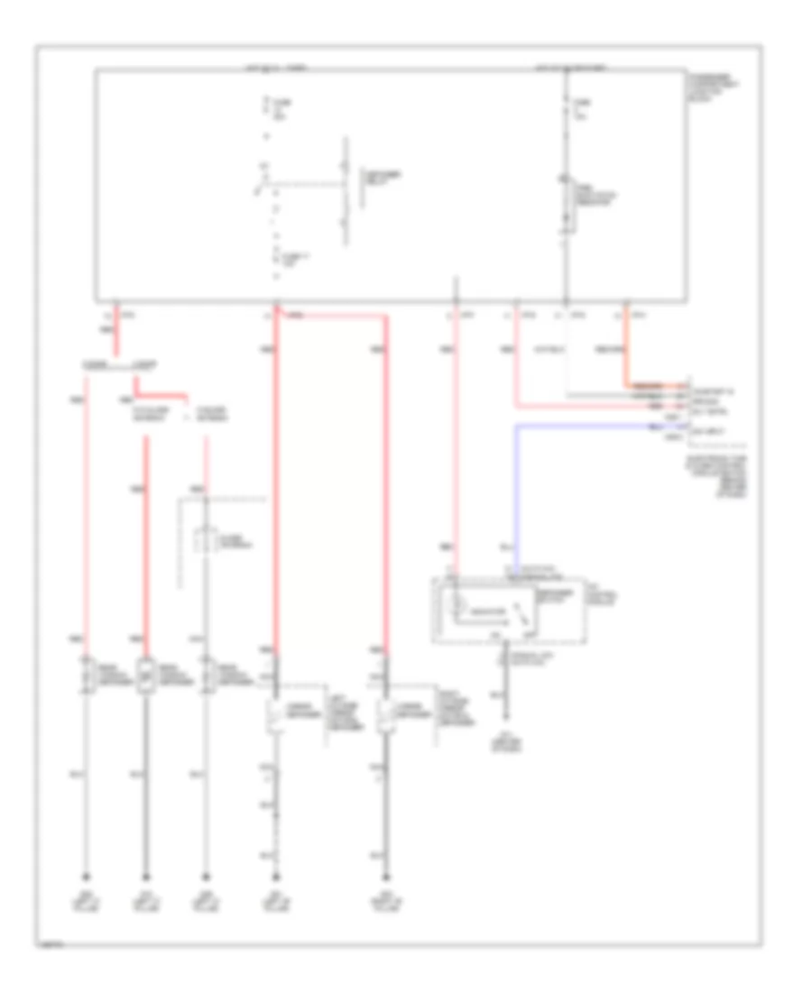
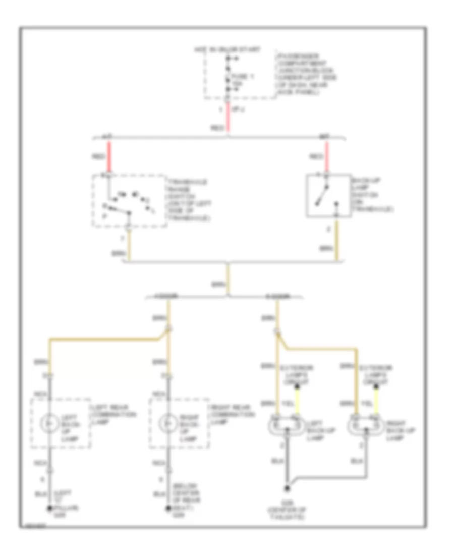
Backup Lamps for Hyundai Elantra GT 2002
 https://portal-diagnostov.com/license.html
Automotive Electricians Portal FZCO
Automotive Electricians Portal FZCO
https://portal-diagnostov.com/license.html
https://portal-diagnostov.com/license.html
Automotive Electricians Portal FZCO
Automotive Electricians Portal FZCOList of elements for Backup Lamps for Hyundai Elantra GT 2002:
- "c" pillar) g05
- 4 door
- 5 door
- A/t
- Back-up lamp switch (on transaxle)
- Exterior lamps circuit
- Fuse 1 10a
- G28 (center of tailgate)
- Hot in on or start
- I/p-j
- Left back- up lamp
- Left back-up lamp
- Left rear combination lamp
- M/t
- Nca
- Of rear seat) g09
- Passenger compartment junction block (under left side of dash, near kick panel)
- Red
- Right back- up lamp
- Right back-up lamp
- Right rear combination lamp
- Transaxle range switch (on top left side of transaxle)
Exterior Lamps Wiring Diagram, 4 Door (1 of 2) for Hyundai Elantra GT 2002
 https://portal-diagnostov.com/license.html
Automotive Electricians Portal FZCO
Automotive Electricians Portal FZCO
https://portal-diagnostov.com/license.html
https://portal-diagnostov.com/license.html
Automotive Electricians Portal FZCO
Automotive Electricians Portal FZCOList of elements for Exterior Lamps Wiring Diagram, 4 Door (1 of 2) for Hyundai Elantra GT 2002:
- (below center of rear seat) g09
- (center of dash) g14
- (etacm) a
- (left "c" pillar) g05
- (near battery) g15
- (right front frame rail) g16
- (tacm) b
- (under left side of dash, near kick panel) passenger compartment junction block
- Drl control module (on left front inner fender panel)
- E13
- Engine compartment relay & fuse box (in left front corner of engine compartment, behind battery)
- Etacm/tacm (under center of dash, below radio)
- Fuse 16 15a
- Fuse 6 10a
- Fuse 7 10a
- Fusible link (batt) 50a
- Head
- High mounted stop lamp
- Hot at all times
- I/p-a
- I/p-b
- I/p-d
- I/p-h
- I/p-j
- Input
- J/c c91 (left side of dash)
- J/c e61
- J/c m36 (under left side of dash)
- J/c m45 (left kick panel)
- J/c m46 (under passenger's seat)
- Left front side marker lamp
- Left license lamp
- Left rear combin- ation lamp
- Light switch
- M01-2
- M25-1
- M25-2
- M26
- Multi- function switch
- Nca
- Nca nca
- Off
- Output
- Park
- Pnk
- Red
- Right front side marker lamp
- Right license lamp
- Right rear combination lamp
- Stop
- Stop lamp switch (on brake pedal bracket)
- Tail
- Tail lamp relay
- Tail lamp relay auto cut control input
- Tail lamp relay auto cut control output
- Tail lamp relay on control
- Turn
- W/ cruise
- W/ drl
- W/ glass
- W/ spoiler
- W/o cruise
Exterior Lamps Wiring Diagram, 4 Door (2 of 2) for Hyundai Elantra GT 2002
 https://portal-diagnostov.com/license.html
Automotive Electricians Portal FZCO
Automotive Electricians Portal FZCO
https://portal-diagnostov.com/license.html
https://portal-diagnostov.com/license.html
Automotive Electricians Portal FZCO
Automotive Electricians Portal FZCOList of elements for Exterior Lamps Wiring Diagram, 4 Door (2 of 2) for Hyundai Elantra GT 2002:
- (center of dash) g12 g13 (left side of dash)
- (center of dash) g14
- (near battery) g15
- (right front frame rail) g16
- (w/o trip)
- (w/o trip) (w/trip)
- (w/trip)
- Coil control
- Etacm (under center of dash, below radio)
- Flasher unit
- Fuse 1 10a
- Fuse 4 10a
- Ground
- Hazard relay (w/etacm) (in passenger compartment relay box)
- Hazard relay ctrl
- Hazard switch
- Hot at all times
- Hot in on or start
- I/p-b
- I/p-d
- I/p-g
- I/p-h
- I/p-j
- Illumination
- Instrument cluster
- Interior lights system
- Left
- Left front turn signal lamp
- Left turn indicator
- M01-2
- M09-1
- M09-3
- M10-1
- M10-2
- M25-3
- Multi- function switch
- Nca
- Off
- Passenger compartment junction block (under left side of dash, near kick panel)
- Passenger compartment relay box (under left side of dash, beside passenger, compartment junction block)
- Pnk
- Power
- Red
- Right
- Right front turn signal lamp
- Right turn indicator
- Turn signal switch
Exterior Lamps Wiring Diagram, 5 Door (1 of 2) for Hyundai Elantra GT 2002
 https://portal-diagnostov.com/license.html
Automotive Electricians Portal FZCO
Automotive Electricians Portal FZCO
https://portal-diagnostov.com/license.html
https://portal-diagnostov.com/license.html
Automotive Electricians Portal FZCO
Automotive Electricians Portal FZCOList of elements for Exterior Lamps Wiring Diagram, 5 Door (1 of 2) for Hyundai Elantra GT 2002:
- (center of dash) g14
- (center of tailgate) g28
- (etacm) a
- (left "c" pillar) g06
- (right rear of cargo area) g08
- (tacm) b
- (under left side of dash, near kick panel) passenger compartment junction block
- Back-up lights circuit
- Drl control module (on left front inner fender panel)
- E13
- Engine compartment relay & fuse box (in left front corner of engine compartment behind battery)
- Engine compartment relay & fuse box (in left front corner of engine compartment, behind battery)
- Etacm/tacm (under center of dash, below radio)
- Fuse 16 15a
- Fuse 6 10a
- Fuse 7 10a
- Fusible link (batt) 50a
- G28 (center of tailgate)
- Head
- High mounted stop lamp
- Hot at all times
- I/p-a
- I/p-b
- I/p-d
- I/p-h
- I/p-j
- Input
- J/c c91 (left side of dash)
- J/c e61
- J/c m36 (under left side of dash)
- J/c m45 (left kick panel)
- J/c m46 (under passenger's seat)
- Left back-up lamp (tail/ back-up)
- Left license lamp
- Left rear combination lamp
- Left rear side marker lamp
- Light switch
- M01-2
- M25-1
- M25-2
- M26
- Multi- function switch
- Nca
- Nca nca
- Off
- Output
- Park
- Pnk
- Red
- Right back-up lamp (back-up/ tail)
- Right license lamp
- Right rear combination lamp
- Right rear side marker lamp
- Stop
- Stop lamp switch (on brake pedal bracket)
- Tail
- Tail lamp relay
- Tail lamp relay auto cut control input
- Tail lamp relay auto cut control output
- Tail lamp relay on control
- Turn
- W/ cruise
- W/ drl
- W/o cruise
Exterior Lamps Wiring Diagram, 5 Door (2 of 2) for Hyundai Elantra GT 2002
 https://portal-diagnostov.com/license.html
Automotive Electricians Portal FZCO
Automotive Electricians Portal FZCO
https://portal-diagnostov.com/license.html
https://portal-diagnostov.com/license.html
Automotive Electricians Portal FZCO
Automotive Electricians Portal FZCOList of elements for Exterior Lamps Wiring Diagram, 5 Door (2 of 2) for Hyundai Elantra GT 2002:
- (center of dash) g12 g13 (left side of dash)
- (center of dash) g14
- (near battery) g15
- (right front frame rail) g16
- (w/o trip)
- (w/o trip) (w/trip)
- (w/trip)
- Coil control
- Etacm (under center of dash, below radio)
- Flasher unit
- Fuse 1 10a
- Fuse 4 10a
- Ground
- Hazard relay (w/etacm) (in passenger compartment relay box)
- Hazard relay ctrl
- Hazard switch
- Hot at all times
- Hot in on or start
- I/p-b
- I/p-d
- I/p-g
- I/p-h
- I/p-j
- Illumination
- Instrument cluster
- Interior lights system
- Left
- Left front side marker lamp
- Left front turn signal lamp (park/ turn)
- Left turn indicator
- M01-2
- M09-1
- M09-3
- M10-1
- M10-2
- M25-3
- Multi- function switch
- Nca
- Off
- Passenger compartment junction block (under left side of dash, near kick panel)
- Passenger compartment relay box (under left side of dash, beside passenger compartment, junction block)
- Pnk
- Power
- Red
- Right
- Right front side marker lamp
- Right front turn signal lamp (park/ turn)
- Right turn indicator
- Turn signal switch
GROUND DISTRIBUTION
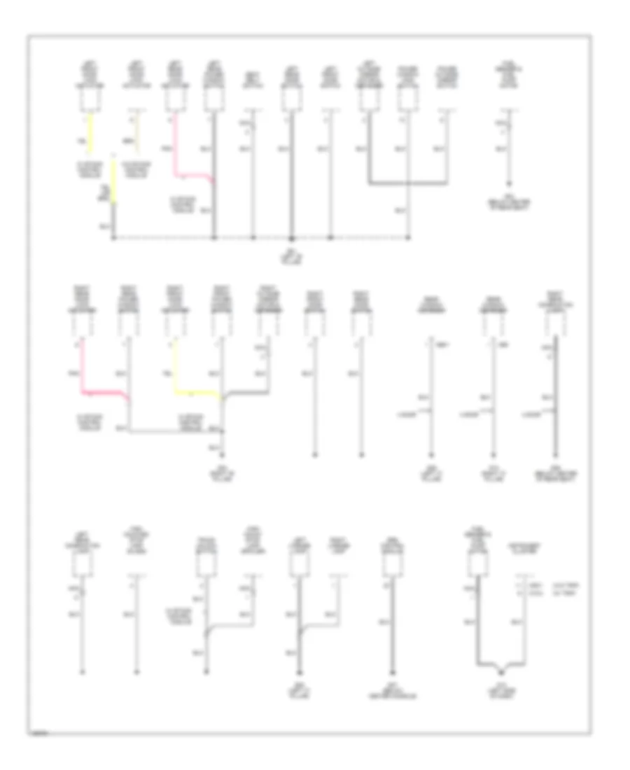
Ground Distribution Wiring Diagram (1 of 4) for Hyundai Elantra GT 2002
 https://portal-diagnostov.com/license.html
Automotive Electricians Portal FZCO
Automotive Electricians Portal FZCO
https://portal-diagnostov.com/license.html
https://portal-diagnostov.com/license.html
Automotive Electricians Portal FZCO
Automotive Electricians Portal FZCOList of elements for Ground Distribution Wiring Diagram (1 of 4) for Hyundai Elantra GT 2002:
- (w/ trip)
- (w/o trip)
- 4 door
- Fuel sender & fuel pump motor
- G01 (left "b" pillar)
- G03 (right "b" pillar)
- G04 (below center of rear seat)
- G05 (left "c" pillar)
- G09 (below center of rear seat)
- G10 (right "c" pillar)
- G13 (left side of dash)
- G27 (below center console)
- G29 (left "c" pillar)
- High mount stop lamp (spoiler)
- High mounted stop lamp (glass)
- Instrument cluster
- Left front door lock actuator
- Left front door switch
- Left license lamp
- Left outside mirror motor & defogger
- Left rear combination lamp
- Left rear door lock actuator
- Left rear door switch
- Left rear power window switch
- M09-1
- M10-2
- M66-1
- M69
- Nca
- Pnk
- Power outside mirror switch
- Power window main switch
- Rear window defogger
- Right front door lock actuator
- Right front door switch
- Right front power window switch
- Right license lamp
- Right outside mirror motor & defogger
- Right rear combination lamp
- Right rear door lock actuator
- Right rear door switch
- Right rear power window switch
- Seat belt switch
- Srs control module
- Trunk unlock switch
- W/ etacs control module
- W/o etacs control module
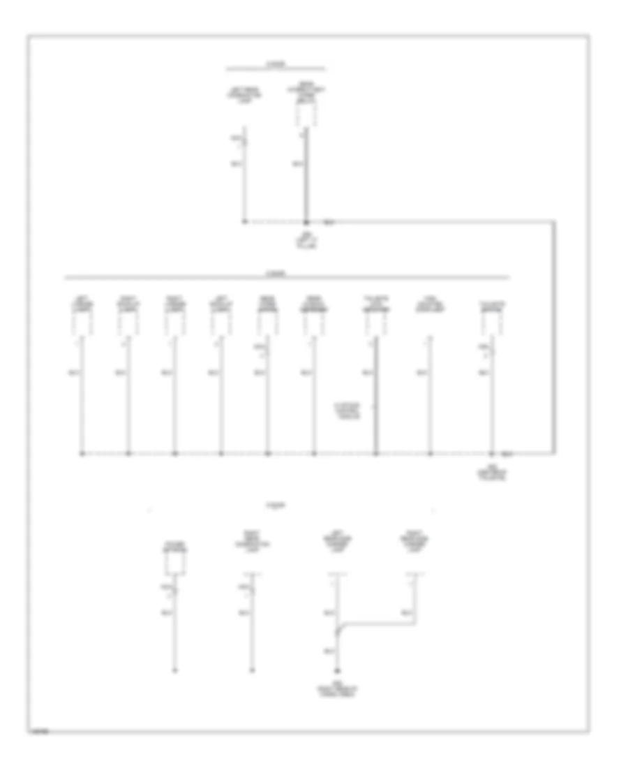
Ground Distribution Wiring Diagram (2 of 4) for Hyundai Elantra GT 2002
 https://portal-diagnostov.com/license.html
Automotive Electricians Portal FZCO
Automotive Electricians Portal FZCO
https://portal-diagnostov.com/license.html
https://portal-diagnostov.com/license.html
Automotive Electricians Portal FZCO
Automotive Electricians Portal FZCOList of elements for Ground Distribution Wiring Diagram (2 of 4) for Hyundai Elantra GT 2002:
- 5 door
- G06 (left "c" pillar)
- G08 (right rear of cargo area)
- G28 (center of tailgate)
- High mounted stop lamp
- Left back-up lamp
- Left license lamp
- Left rear combination lamp
- Left rear side marker lamp
- Nca
- Power antenna
- Rear intermittent wiper relay
- Rear window defogger
- Rear wiper motor
- Right back-up lamp
- Right license lamp
- Right rear combination lamp
- Right rear side marker lamp
- Tailgate lock actuator
- Tailgate switch
- W/ etacs control module
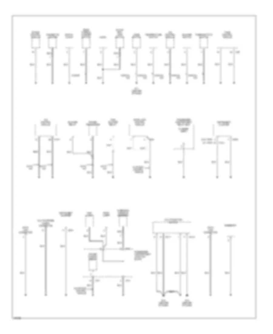
Ground Distribution Wiring Diagram (3 of 4) for Hyundai Elantra GT 2002
 https://portal-diagnostov.com/license.html
Automotive Electricians Portal FZCO
Automotive Electricians Portal FZCO
https://portal-diagnostov.com/license.html
https://portal-diagnostov.com/license.html
Automotive Electricians Portal FZCO
Automotive Electricians Portal FZCOList of elements for Ground Distribution Wiring Diagram (3 of 4) for Hyundai Elantra GT 2002:
- (w/ trip)
- (w/o trip)
- 5 door
- A/c control module
- Audio
- Auto a/c
- Blower relay
- Blower switch
- Cigarette lighter
- Data link connector
- Digital clock
- Door lock control module
- Etacs control module
- Flasher unit
- G11 (center of dash)
- G12 (center of dash)
- G14 (center of dash)
- Glove box lamp switch
- High blower relay
- I/p-c
- I/p-f
- I/p-h
- Instrument cluster
- M01-1
- M01-2
- M09-1
- M09-2
- M10-1
- M19-1
- M26
- M32
- Manual a/c
- Map lamp
- Mode switch
- Multifunction switch
- Multipurpose check connector
- Nca
- Overhead console assmebly
- Passenger compartment junction block
- Passenger compartment relay box
- Power transistor
- Power window relay
- Rear wiper & washer switch
- Rheostat
- Room lamp
- Tacs control module
- Temperature switch
- Thermostatic switch
- W/ etacs control module
- W/o etacs control module
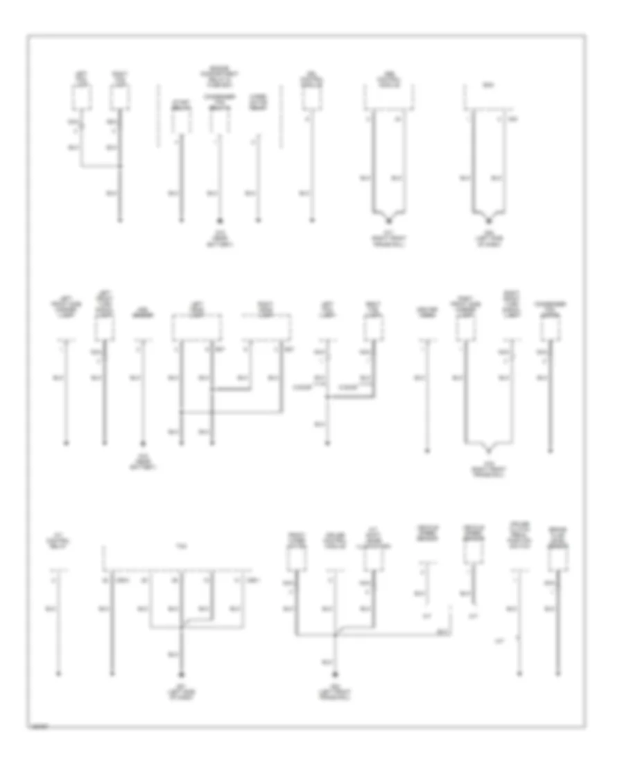
Ground Distribution Wiring Diagram (4 of 4) for Hyundai Elantra GT 2002
 https://portal-diagnostov.com/license.html
Automotive Electricians Portal FZCO
Automotive Electricians Portal FZCO
https://portal-diagnostov.com/license.html
https://portal-diagnostov.com/license.html
Automotive Electricians Portal FZCO
Automotive Electricians Portal FZCOList of elements for Ground Distribution Wiring Diagram (4 of 4) for Hyundai Elantra GT 2002:
- 5 door
- A/t
- A/t control relay
- A/t shift lever illumination
- Abs control module
- Aqs sensor
- Brake fluid level sensor
- C83
- C86-1
- C86-3
- Center horn
- Condenser fan motor
- Condenser fan relay 2
- Cruise clutch pedal position switch
- Cruise control module
- Drl control module
- E07
- E27
- Ecm
- Engine compartment relay & fuse box
- Front wiper motor
- G15 (near battery)
- G16 (right front frame rail)
- G17 (right front frame rail)
- G21 (left side of dash)
- G22 (left side of dash)
- G23 (left front frame rail)
- Left fog lamp
- Left front side marker lamp
- Left front turn signal lamp
- Left head lamp
- M/t
- Nca
- Right fog lamp
- Right front side marker lamp
- Right front turn signal lamp
- Right head lamp
- Start rel;ay
- Tcm
- Vehicle speed sensor
- Wiper motor relay
HEADLIGHTS
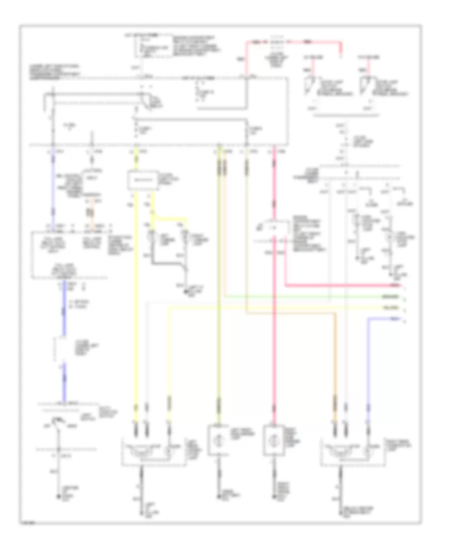
Headlight Wiring Diagram, with DRL (1 of 2) for Hyundai Elantra GT 2002
 https://portal-diagnostov.com/license.html
Automotive Electricians Portal FZCO
Automotive Electricians Portal FZCO
https://portal-diagnostov.com/license.html
https://portal-diagnostov.com/license.html
Automotive Electricians Portal FZCO
Automotive Electricians Portal FZCOList of elements for Headlight Wiring Diagram, with DRL (1 of 2) for Hyundai Elantra GT 2002:
- (etacs cm)
- (in left front corner of engine compartment, behind battery) engine compartment relay & fuse box
- (tacs cm)
- (w/ trip)
- (w/o trip)
- Dimmer/ passing switch
- Drl resistor (on left fenderwell)
- Em02
- Etacs (or tacs) control module (under center of dash, below radio)
- Flash
- Front fog lamp switch
- Fuse 10a
- G14 (center of dash)
- G15 (near battery)
- Head
- Head- light relay (high)
- Head- light relay (low)
- Headlamp (high) fuse 15a
- Headlamp (low) fuse 15a
- High
- High beam indicator
- Hot at all times
- Hot at on
- I/p-b
- Instrument cluster
- Joint connector e56
- Joint connector e60
- Joint connector m36 (left side of dash)
- Left headlamp
- Light switch
- Low
- M09-2
- M10-1
- M25-2
- M26
- Multifunction switch
- Nca
- Off
- Park
- Passenger compartment junction block (under left side of dash, near kick panel)
- Right headlamp
- To drl control module (diagram 2 of 2)
- To front foglight relay (diagram 2 of 2)
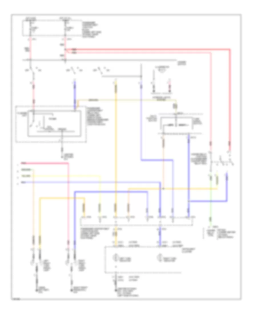
Headlight Wiring Diagram, with DRL (2 of 2) for Hyundai Elantra GT 2002
 https://portal-diagnostov.com/license.html
Automotive Electricians Portal FZCO
Automotive Electricians Portal FZCO
https://portal-diagnostov.com/license.html
https://portal-diagnostov.com/license.html
Automotive Electricians Portal FZCO
Automotive Electricians Portal FZCOList of elements for Headlight Wiring Diagram, with DRL (2 of 2) for Hyundai Elantra GT 2002:
- (4-door)
- (5-door)
- (w/ trip)
- (w/o trip)
- Diode z02
- Drl control module (on left front inner fender panel)
- Drl fuse 15a
- Drl relay
- E20-2
- Em02
- Engine compartment relay & fuse box (in left front corner of engine compartment, behind battery)
- From drl resistor (diagram 1 of 2)
- From engine compt relay & fuse box, joint connector e56 (diagram 1 of 2)
- From etacs (or tacs) control module (diagram 1 of 2)
- From front fog lamp switch (diagram 1 of 2)
- From headlight relay (diagram 1of2)
- Front fog fuse 15a
- Front foglight indicator
- Front foglight relay
- Fuse 10a
- Fusible link (batt) fuse 100a
- Fusible link (batt) fuse 50a
- G15 (near battery)
- Generator
- Hot at all times
- I/p-a
- I/p-b
- I/p-g
- Instrument cluster
- Interior lights system
- Joint connector e62
- Joint connector m36 (left side of dash)
- Left front fog lamp
- M09-1
- M10-2
- Nca
- Parking brake switch (on base of parking brake lever)
- Passenger compartment junction block (under left side of dash, near kick panel)
- Pnk
- Power & control circuit
- Red
- Right front fog lamp
- Starting/ charging system
- Tail relay
- Taillight relay
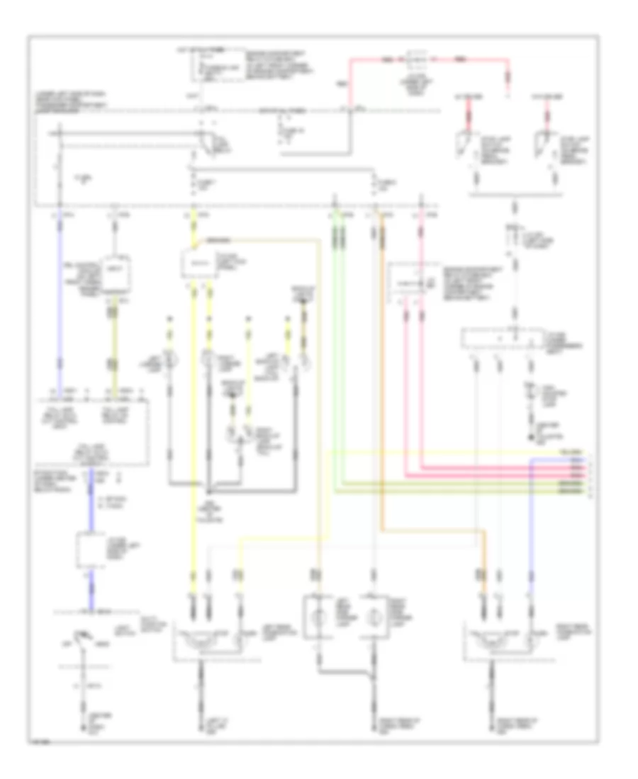
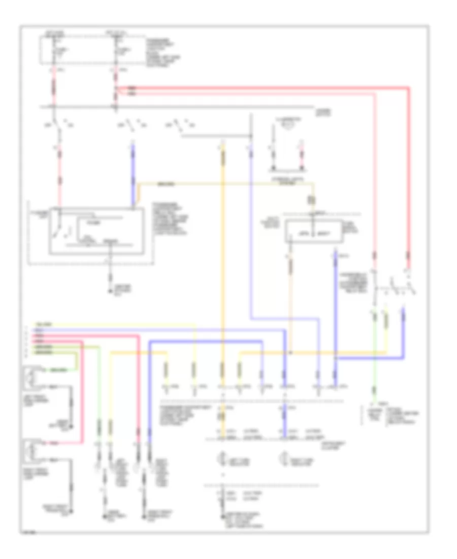
Headlight Wiring Diagram, without DRL for Hyundai Elantra GT 2002
 https://portal-diagnostov.com/license.html
Automotive Electricians Portal FZCO
Automotive Electricians Portal FZCO
https://portal-diagnostov.com/license.html
https://portal-diagnostov.com/license.html
Automotive Electricians Portal FZCO
Automotive Electricians Portal FZCOList of elements for Headlight Wiring Diagram, without DRL for Hyundai Elantra GT 2002:
- (4-door)
- (5-door)
- (etacs cm)
- (in left front corner of engine compartment, behind battery) engine compartment relay & fuse box
- (tacs cm)
- (under left side of dash, near kick panel) passenger compartment junction block
- (w/ trip)
- (w/o trip)
- Dimmer/ passing switch
- Diode z02
- Em02
- Etacs (or tacs) control module (behind center of dash)
- Flash
- Front fog fuse 15a
- Front fog lamp switch
- Front foglight indicator
- Front foglight relay
- Fuse 10a
- Fusible link (batt) fuse 50a
- G14 (center of dash)
- G15 (near battery)
- Head
- Head- light relay (high)
- Head- light relay (low)
- Headlamp (high) fuse 15a
- Headlamp (low) fuse 15a
- High
- High beam indicator
- Hot at all times
- Hot at on
- I/p-a
- I/p-b
- I/p-g
- I/p-h
- Instrument cluster
- Interior lights system
- Joint connector e56
- Joint connector e60
- Joint connector e62
- Joint connector m36 (left side of dash)
- Left front fog lamp
- Left headlamp
- Light switch
- Low
- M09-1
- M09-2
- M10-1
- M10-2
- M25-1
- M25-2
- M26
- Multifunction switch
- Nca
- Off
- Park
- Passenger compartment junction block (under left side of dash, near kick panel)
- Pnk
- Red
- Right front fog lamp
- Right headlamp
- Taillight relay
HORN
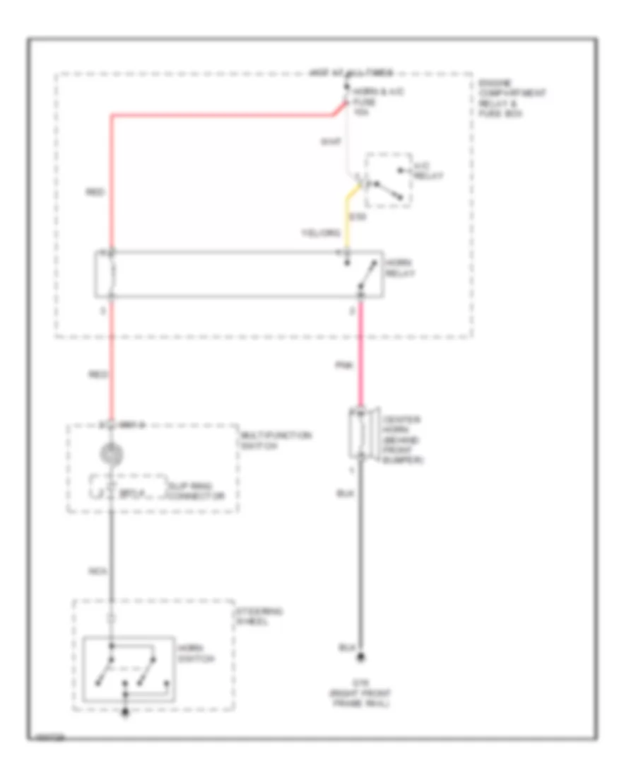
Horn Wiring Diagram for Hyundai Elantra GT 2002
 https://portal-diagnostov.com/license.html
Automotive Electricians Portal FZCO
Automotive Electricians Portal FZCO
https://portal-diagnostov.com/license.html
https://portal-diagnostov.com/license.html
Automotive Electricians Portal FZCO
Automotive Electricians Portal FZCOList of elements for Horn Wiring Diagram for Hyundai Elantra GT 2002:
- A/c relay
- Center horn (behind front bumper)
- E50
- Engine compartment relay & fuse box
- G16 (right front frame rail)
- Horn & a/c fuse 15a
- Horn relay
- Horn switch
- Hot at all times
- M01-3
- M01-4
- Multifunction switch
- Nca
- Pnk
- Red
- Slip ring connector
- Steering wheel
INSTRUMENT CLUSTER
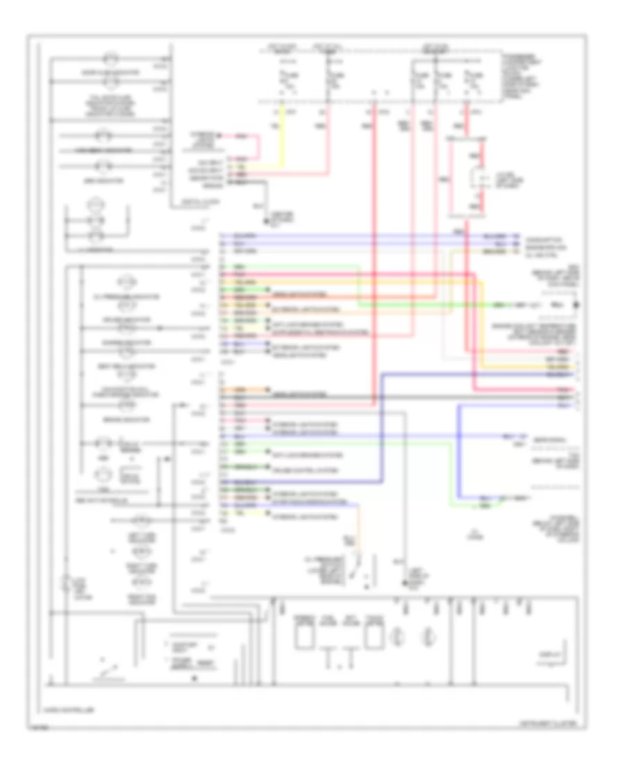
Instrument Cluster Wiring Diagram, Base (1 of 2) for Hyundai Elantra GT 2002
 https://portal-diagnostov.com/license.html
Automotive Electricians Portal FZCO
Automotive Electricians Portal FZCO
https://portal-diagnostov.com/license.html
https://portal-diagnostov.com/license.html
Automotive Electricians Portal FZCO
Automotive Electricians Portal FZCOList of elements for Instrument Cluster Wiring Diagram, Base (1 of 2) for Hyundai Elantra GT 2002:
- (center of dash)
- (left side of dash)
- Abs active module
- Abs indicator
- Anti-lock brakes system
- Brake warning indicator
- Charge indicator
- Chime bell (below left side of dash, right of steering column)
- Cruise control system
- Cruise indicator
- Door ajar indicator
- Engine coolant temperature (ect) sensor & sender (on rear of engine, near coolant outlet)
- Engine coolant temperature gauge
- Etacm (under center of dash, below radio)
- Exterior lights system
- Front fog indicator
- Fuel gauge
- Fuse 10a
- G12
- G13
- G14
- Headlights system
- High beam indicator
- Hot at all times
- Hot in on or start
- I/p-g
- I/p-h
- I/p-j
- Illumination (4 bulbs)
- Instrument cluster
- Interior lights system
- Lcd illumination
- Left turn indicator
- Low fuel indicator
- M09-1
- M09-2
- M09-3
- M25-2
- Malfunction indicator lamp (mil) "check engine"
- Mo9-1
- Mo9-2
- Mo9-3
- Nca
- Oil pressure indicator
- Oil pressure switch (lower left rear of engine)
- Passenger compartment junction block (under left side of dash, near kick panel)
- Pnk
- Red
- Right turn indicator
- Seat belt indicator
- Speedometer
- Srs indicator
- Starting/charging system
- Tachometer
- Tailgate ajar indicator (5 door) trunk lid ajar indicator (4 door)
- Tcs indicator
- Transaxle range switch (on top left side of transaxle)
- Transmissions system
- W/ chime
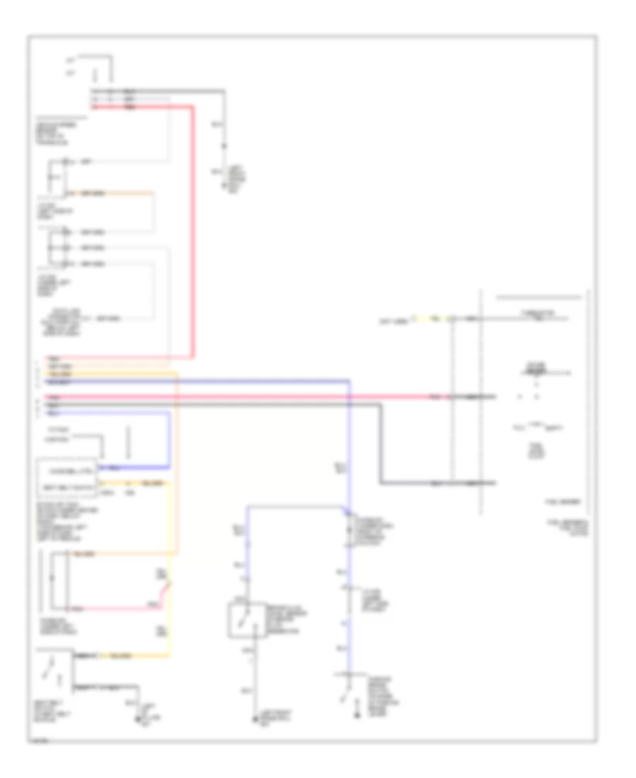
Instrument Cluster Wiring Diagram, Base (2 of 2) for Hyundai Elantra GT 2002
 https://portal-diagnostov.com/license.html
Automotive Electricians Portal FZCO
Automotive Electricians Portal FZCO
https://portal-diagnostov.com/license.html
https://portal-diagnostov.com/license.html
Automotive Electricians Portal FZCO
Automotive Electricians Portal FZCOList of elements for Instrument Cluster Wiring Diagram, Base (2 of 2) for Hyundai Elantra GT 2002:
- (center of dash) g11
- (left "b" pillar) g01
- (left front frame rail) g23
- (left side of dash) g13
- A/t
- Acc/on input
- Brake fluid level sensor (in brake fluid reservoir)
- Data link connector (dlc) (partial) (below left side of dash)
- Digital clock
- Dim input
- Diode z01 (under dash, right of steering column)
- Diode z08 (under left side of dash)
- Ecm (behind left side of dash, above kick panel)
- Empty
- Engine rpm signal
- Etacm or tacm (etacm-under center of dash, below radio) (tacm-behind left side of dash, left of pedals)
- Fuel level float
- Fuel sender
- Fuel sender & fuel pump motor
- Full
- Fuse 10 10a
- Fuse 10a
- Fuse 15a
- Gauge sender
- Ground
- Hot at all times
- Hot in acc or on
- Hot in on or start
- I/p-f
- I/p-g
- I/p-h
- Interior lights system
- J/c c91 (left side of dash)
- J/c c92 (left side of dash)
- J/c m33 (under left side of dash)
- J/c m36 (under left side of dash)
- M/t
- M26
- Memory pwr
- Mil ind ctrl
- Nca
- Parking brake switch (on base of parking brake lever)
- Passenger compartment junction block (under left side of dash, near kick panel)
- Pnk
- Red
- Seat belt switch (in seat belt buckle)
- Seat belt switch m25-2
- Thermistor
- Vehicle speed sensor (on top of transaxle)
- W/etacm
- W/tacm
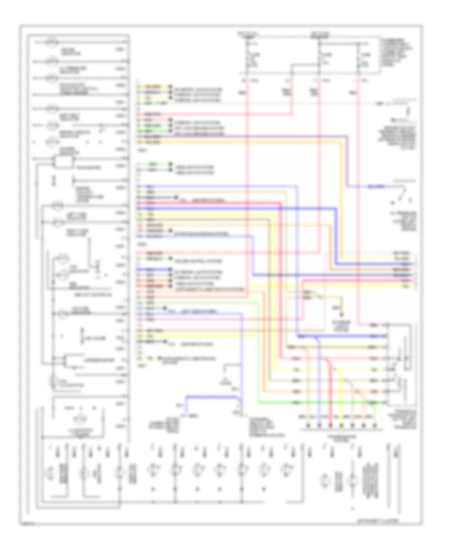
Instrument Cluster Wiring Diagram, Premium Model (1 of 2) for Hyundai Elantra GT 2002
 https://portal-diagnostov.com/license.html
Automotive Electricians Portal FZCO
Automotive Electricians Portal FZCO
https://portal-diagnostov.com/license.html
https://portal-diagnostov.com/license.html
Automotive Electricians Portal FZCO
Automotive Electricians Portal FZCOList of elements for Instrument Cluster Wiring Diagram, Premium Model (1 of 2) for Hyundai Elantra GT 2002:
- (center of dash) g11
- (left side of dash) g13
- A/t
- Abs
- Abs active module
- Acc/on input
- Anti-lock brakes system
- Brake indicator
- C86-1
- Charge indicator
- Chime bell (below left side of dash, right of steering column)
- Consumption
- Cruise control system
- Cruise indicator
- Digital clock
- Dim input
- Display
- Door ajar indicator
- Ecm (behind left side of dash, above kick panel)
- Ect gauge
- Engine coolant temperature (ect) sensor & sender (on rear of engine, near coolant outlet)
- Engine rpm sig
- Exterior lights system
- Front fog indicator
- Fuel gauge
- Fuse 10a
- Fuse 15a
- Gear signal
- Ground
- Headlights system
- High beam indicator
- Hot at all times
- Hot in acc or on
- Hot in on or start
- I/p-f
- I/p-g
- I/p-h
- Illumination
- Instrument cluster
- Interior lights system
- J/c c92 (left side of dash)
- Left turn indicator
- Low fuel indi- cator
- M/t
- M10-1
- M10-2
- Malfunction (mil) check engine indicator
- Memory pwr
- Micro controller
- Mil ind ctrl
- Nca
- Oil pressure indicator
- Oil pressure switch (lower left rear of engine)
- On/start input
- Passenger compartment junction block (under left side of dash, near kick panel)
- Pnk
- Red
- Reset
- Right turn indicator
- Seat belt indicator
- Solid state
- Speedo- meter
- Srs indicator
- Starting/charging system
- Tacho- meter
- Tail gate ajar indicator (5 door) trunk lid ajar indicator (4 door)
- Tcm (behind left side of dash)
- Tcs
- W/ chime
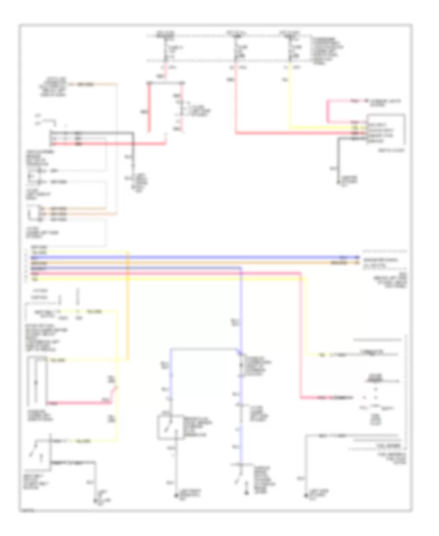
Instrument Cluster Wiring Diagram, Premium Model (2 of 2) for Hyundai Elantra GT 2002
 https://portal-diagnostov.com/license.html
Automotive Electricians Portal FZCO
Automotive Electricians Portal FZCO
https://portal-diagnostov.com/license.html
https://portal-diagnostov.com/license.html
Automotive Electricians Portal FZCO
Automotive Electricians Portal FZCOList of elements for Instrument Cluster Wiring Diagram, Premium Model (2 of 2) for Hyundai Elantra GT 2002:
- (left "b" pillar) g01
- (left front frame rail) g23
- (not used)
- A/t
- Brake fluid level sensor (in brake fluid reservoir)
- Chime bell ctrl
- Data link connector (dlc) (partial) (below left side of dash)
- Diode z01 (under dash, right of steering column)
- Diode z08 (under left side of dash)
- Empty
- Etacm or tacm (etacm-under center of dash, below radio) (tacm-behind left side of dash, left of pedals)
- Fuel level float
- Fuel sender
- Fuel sender & fuel pump motor
- Full
- Gauge sender
- J/c c91 (left side of dash)
- J/c m33 (under left side of dash)
- J/c m36 (under left side of dash)
- M/t
- M25-2
- M26
- Nca
- Parking brake switch (on base of parking brake lever)
- Pnk
- Red
- Seat belt switch
- Seat belt switch (in seat belt buckle)
- Thermistor
- Vehicle speed sensor (on top of transaxle)
- W/etacm
- W/tacm
INTERIOR LIGHTS
Courtesy Lamps Wiring Diagram, with Sunroof for Hyundai Elantra GT 2002
 https://portal-diagnostov.com/license.html
Automotive Electricians Portal FZCO
Automotive Electricians Portal FZCO
https://portal-diagnostov.com/license.html
https://portal-diagnostov.com/license.html
Automotive Electricians Portal FZCO
Automotive Electricians Portal FZCOList of elements for Courtesy Lamps Wiring Diagram, with Sunroof for Hyundai Elantra GT 2002:
- (beneath driver's seat) j/c m46
- (etacm)
- (etacm) (tacm)
- (tacm) (etacm)
- 4 door
- 5 door
- Courtesy
- Door sw (all)
- Door switch
- Etacm/ tacm (under center of dash, below radio)
- Fuse 15a
- G01 (left "b" pillar)
- G03 (right "b" pillar)
- G12 (center of dash)
- G28 (center of tailgate)
- Hot at all times
- I/p-c
- I/p-d
- I/p-g
- I/p-h
- Instrument cluster system
- J/c m33 (left side of dash)
- Left front door lamp
- Left front door switch
- Left rear door switch
- Luggage lamp
- M25-1
- M25-1 m26
- Map
- Nca
- Overhead console lamps
- Passenger compartment junction block
- Passenger compartment junction block (under left side of dash, near kick panel)
- Red
- Right front door lamp
- Right front door switch
- Right rear door switch
- Rm lmp cntrl
- Tail gate switch
- Trunk room lamp
- Trunk room lamp sw sig
- Trunk room lamp switch
- W/ etacm
- W/o etacm
Courtesy Lamps Wiring Diagram, without Sunroof for Hyundai Elantra GT 2002
 https://portal-diagnostov.com/license.html
Automotive Electricians Portal FZCO
Automotive Electricians Portal FZCO
https://portal-diagnostov.com/license.html
https://portal-diagnostov.com/license.html
Automotive Electricians Portal FZCO
Automotive Electricians Portal FZCOList of elements for Courtesy Lamps Wiring Diagram, without Sunroof for Hyundai Elantra GT 2002:
- (beneath driver's seat) j/c m46
- (etacm)
- (etacm) (tacm)
- (tacm) (etacm)
- 4 door
- 5 door
- Door
- Door sw (all)
- Door switch
- Etacm/ tacm (under center of dash, below radio)
- Fuse 15a
- G01 (left "b" pillar)
- G03 (right "b" pillar)
- G12 (center of dash)
- G28 (center of tailgate)
- Hot at all times
- I/p-c
- I/p-d
- I/p-g
- I/p-h
- Instrument cluster system
- J/c m33 (left side of dash)
- Left front door lamp
- Left front door switch
- Left rear door switch
- Luggage lamp
- M25-1
- M25-1 m26
- Map lamps
- Nca
- Off
- Passenger compartment junction block
- Passenger compartment junction block (under left side of dash, near kick panel)
- Red
- Right front door lamp
- Right front door switch
- Right rear door switch
- Rm lmp cntrl
- Room lamp
- Tail gate switch
- Trunk room lamp
- Trunk room lamp sw sig
- Trunk room lamp switch
- W/ etacm
- W/o etacm
Instrument Illumination Wiring Diagram for Hyundai Elantra GT 2002
 https://portal-diagnostov.com/license.html
Automotive Electricians Portal FZCO
Automotive Electricians Portal FZCO
https://portal-diagnostov.com/license.html
https://portal-diagnostov.com/license.html
Automotive Electricians Portal FZCO
Automotive Electricians Portal FZCOList of elements for Instrument Illumination Wiring Diagram for Hyundai Elantra GT 2002:
- (manual a/c)
- A w/ trip
- A/c control module illum
- A/t shift lever illum
- Ashtray illum
- Audio illum
- B w/o trip
- Cigarette lighter illum
- Digital clock illum
- Drl control module (left side of dash)
- Engine compartment relay & fuse box (left front of engine compartment)
- Etacs (or tacs) control module (center of dash)
- Fuse 10a
- Fusible link (batt) 50a
- G01 (left "b" pillar)
- G03 (right "b" pillar)
- G11 (center of dash)
- G14 (center of dash)
- G23 (left front frame rail)
- Glove box lamp
- Glove box lamp switch
- Hazard switch illum
- Head
- Hot at all times
- I/p-a
- I/p-b
- I/p-h
- I/p-j
- Illumination
- Instrument cluster
- J/c m08 (left side of dash)
- J/c m36 (left side of dash)
- Junction connector m08 (left side of dash)
- Left rear power window switch
- Light switch
- M09-1
- M09-3
- M10-2
- M19-1 (auto a/c)
- M20
- M25-1 (etacs cm)
- M25-2
- M26 (tacs cm)
- Multifunction switch
- Nca
- Off
- Park
- Passenger compartment junction block (left side of dash)
- Pnk
- Power window main switch
- Rear wiper & washer switch
- Red
- Rheostat
- Right front power window switch
- Right rear power window switch
- Short connector
- Taillight relay
- Tcs switch illum
POWER ANTENNA
Power Antenna Wiring Diagram for Hyundai Elantra GT 2002
 https://portal-diagnostov.com/license.html
Automotive Electricians Portal FZCO
Automotive Electricians Portal FZCO
https://portal-diagnostov.com/license.html
https://portal-diagnostov.com/license.html
Automotive Electricians Portal FZCO
Automotive Electricians Portal FZCOList of elements for Power Antenna Wiring Diagram for Hyundai Elantra GT 2002:
- Acc/on input
- Antenna relay
- Audio
- Down
- Fuse 10a
- Fuse 20a
- G08 (right rear side of trunk)
- Hot at all times
- Hot in acc or on
- I/p-d
- I/p-f
- Joint connector m33 (left side of dash)
- Nca
- Passenger compartment junction block (left side of dash)
- Power antenna
- Pwr ant sig
- Red
POWER DISTRIBUTION
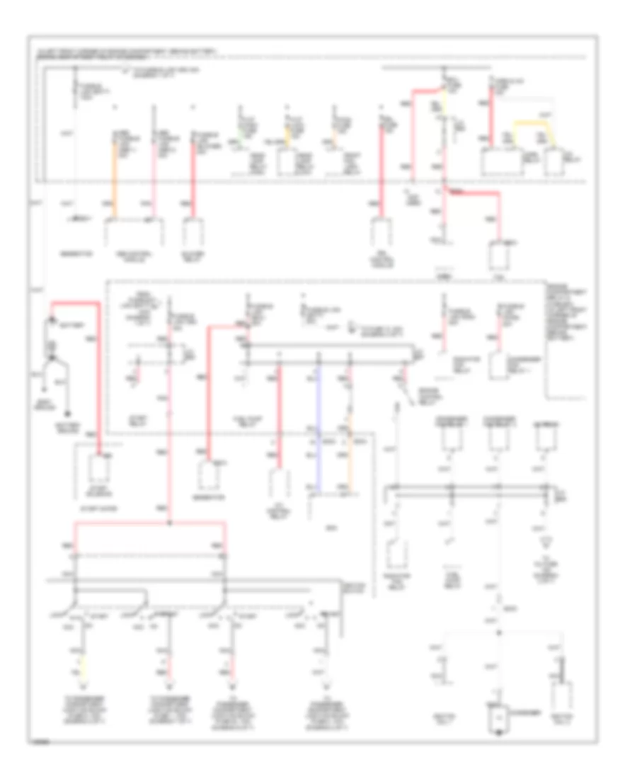
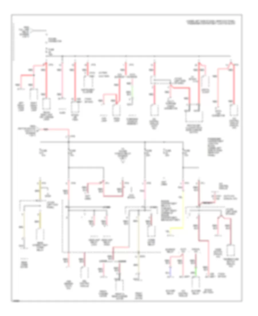
Power Distribution Wiring Diagram (1 of 7) for Hyundai Elantra GT 2002
 https://portal-diagnostov.com/license.html
Automotive Electricians Portal FZCO
Automotive Electricians Portal FZCO
https://portal-diagnostov.com/license.html
https://portal-diagnostov.com/license.html
Automotive Electricians Portal FZCO
Automotive Electricians Portal FZCOList of elements for Power Distribution Wiring Diagram (1 of 7) for Hyundai Elantra GT 2002:
- (in left front corner of engine compartment, behind battery) engine compartment relay & fuse box
- (not used)
- A/c relay
- A/t control relay
- Abs control module
- Abs fusible link (abs 1) 30a
- Abs fusible link (abs 2) 30a
- Acc
- Battery
- Battery ground
- Blower relay
- Body ground
- C86-2
- Condenser
- Condenser fan relay 1
- Condenser fan relay 2
- Drl control module
- Drl fuse 15a
- E20-1
- E20-2
- E68
- Ec03
- Ec04
- Ecm
- Ecu fuse 10a
- Engine compartment relay & fuse box (in left front corner of engine compartment, behind battery)
- Engine control relay
- F/fog fuse 15a
- From fusible link (batt) a 100a (diagram 1 of 7)
- Front fog lamp relay
- Fuel pump relay
- Fusible link (batt) 100a
- Fusible link (batt) 50a
- Fusible link (blower) 30a
- Fusible link (cond) 20a
- Fusible link (ecu) 20a red
- Fusible link (ign) 30a
- Fusible link (rad) 20a
- Generator
- H/lp (high) fuse 15a
- H/lp (low) fuse 15a
- Head- lamp relay (high)
- Head- lamp relay (low)
- Horn & a/c fuse 15a
- Horn relay
- Ignition coil 1
- Ignition coil 2
- Ignition switch
- J/c e55
- J/c e57
- J/c e58
- J/c e62
- Lock
- Nca
- Pnk
- Radiator fan relay
- Red
- Siren
- Start
- Start motor
- Start relay
- Start solenoid
- Tcm
- To fuse 13, 30a (diagram 3 of 7)
- To fusible link (ign) 30a (diagram 1 0f 7)
- To inj fuse 15a (diagram 2 of 7)
- To passenger compartment junction block (fuse 1, 10a) (diagram 7 of 7)
- To passenger compartment junction block (fuse 20, 10a) (diagram 6 of 7)
- To passenger compartment junction block (fuse 8, 10a) (diagram 2 of 7)
- To passenger compartment junction block (fuse 9, 10a) (diagram 2 of 7)
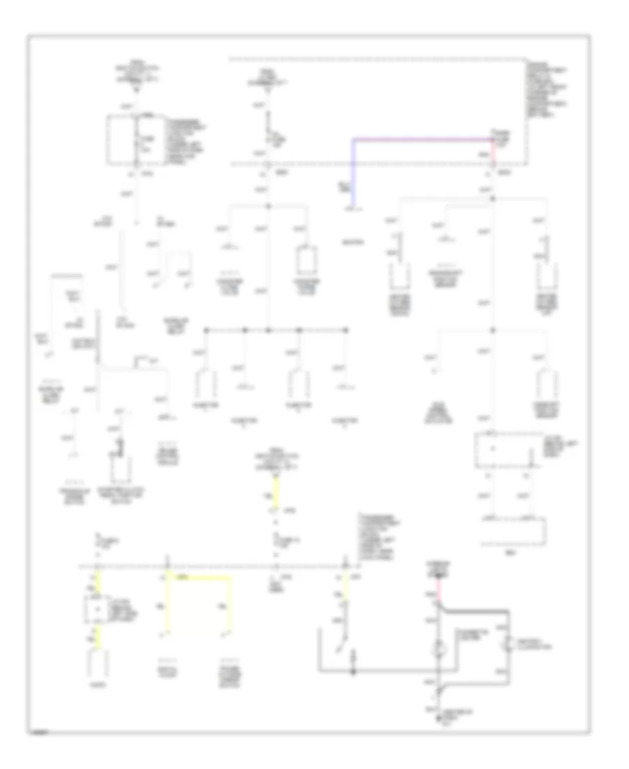
Power Distribution Wiring Diagram (2 of 7) for Hyundai Elantra GT 2002
 https://portal-diagnostov.com/license.html
Automotive Electricians Portal FZCO
Automotive Electricians Portal FZCO
https://portal-diagnostov.com/license.html
https://portal-diagnostov.com/license.html
Automotive Electricians Portal FZCO
Automotive Electricians Portal FZCOList of elements for Power Distribution Wiring Diagram (2 of 7) for Hyundai Elantra GT 2002:
- (center of dash) g11
- (not used)
- A/t
- Ashtray illumination
- Audio
- Burglar alarm relay
- Camshaft position sensor
- Canister close valve
- Canister purge valve
- Cigarette lighter
- Crankshaft position sensor
- Cruise control module
- Digital clock
- Ec03
- Ecm
- Engine compartment relay & fuse box (in left front corner of engine compartment, behind battery)
- From ignition switch (cavity 1) (diagram 1 of 7)
- From ignition switch (cavity 4) (diagram 1 of 7)
- From j/c e58 diagram 1 of 7
- Fuse 10a
- Fuse 18 15a
- Fuse 9 10a
- Heated oxygen sensor (down)
- Heated oxygen sensor (up)
- I/p-d
- I/p-e
- I/p-f
- I/p-g
- Idle speed control actuator
- Inj fuse 15a
- Injector
- Interior lights system
- J/c c91 (behind left side of dash)
- J/c m33 (behind left side of dash)
- M/t
- Nca
- Passenger compartment junction block (under left side of dash, near kick panel)
- Pnk
- Power outside mirror switch
- Smatra
- Snsr fuse 1oa
- Starter clutch pedal position switch
- Transaxle range switch
- W/ etacm
- W/o etacm
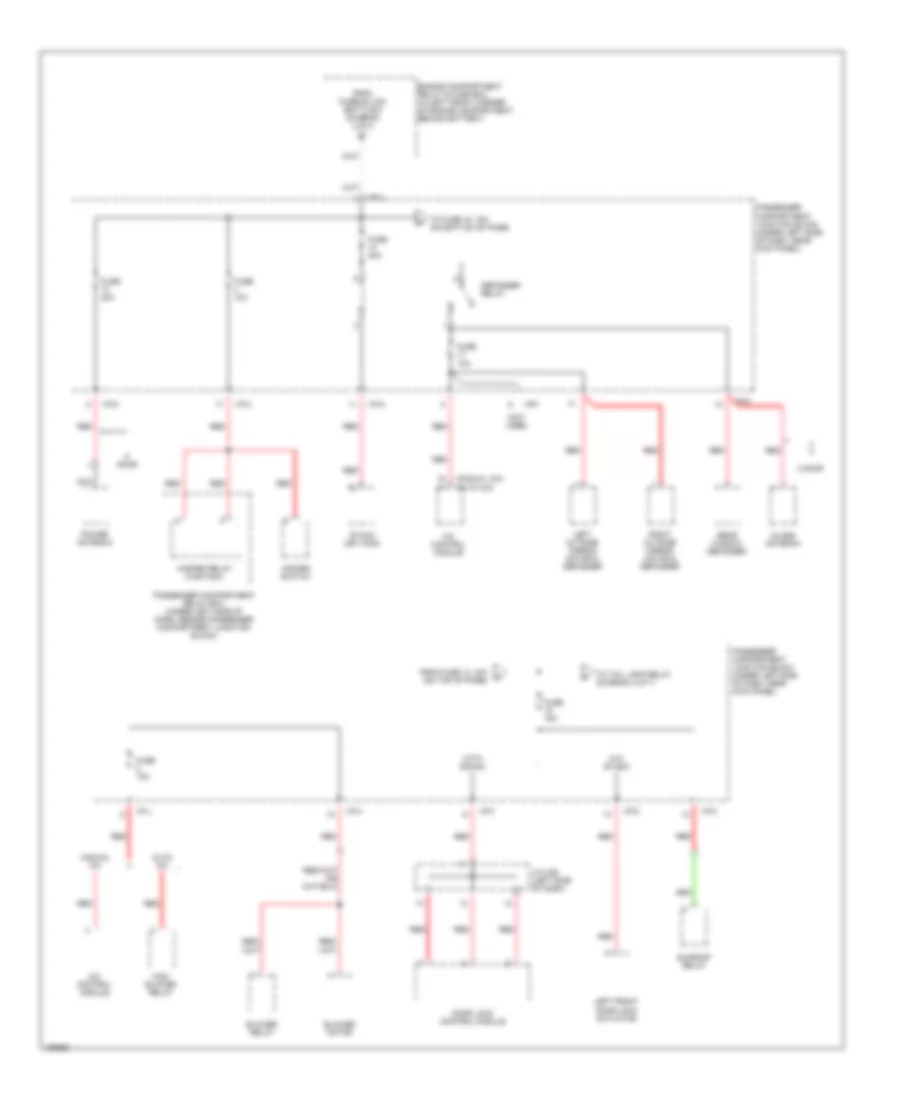
Power Distribution Wiring Diagram (3 of 7) for Hyundai Elantra GT 2002
 https://portal-diagnostov.com/license.html
Automotive Electricians Portal FZCO
Automotive Electricians Portal FZCO
https://portal-diagnostov.com/license.html
https://portal-diagnostov.com/license.html
Automotive Electricians Portal FZCO
Automotive Electricians Portal FZCOList of elements for Power Distribution Wiring Diagram (3 of 7) for Hyundai Elantra GT 2002:
- (manual a/c) (auto a/c)
- (not used)
- 4 door
- A/c control module
- Auto a/c
- Blower motor
- Blower relay
- Defogger relay
- Door
- Door lock control module
- Engine compartment relay & fuse box (in left front corner of engine compartment, behind battery)
- Etacm (or tacm)
- From fuse 13, 30a (on top of page)
- From fusible link (batt) 50a (diagram 1 of 7)
- Fuse 10a
- Fuse 15a
- Fuse 20a
- Fuse 30a
- Glass antenna
- Hazard relay (w/etacm)
- Hazard switch
- High blower relay
- I/p-a
- I/p-c
- I/p-d
- I/p-f
- I/p-g
- I/p-h
- I/p-j
- J/c m36 (left side of dash)
- Left front door lock actuator
- Left outside mirror motor & defogger
- Manual a/c
- Nca
- Passenger compartment junction block (under left side of dash, near kick panel)
- Passenger compartment relay box (under left side of dash, beside passenger compartment junction block)
- Power antenna
- Rear window defogger
- Red
- Right outside mirror motor & defogger
- Sunroof relay
- To fuse 15, 15a (on bottom of page)
- To tail lamp relay (diagram 4 of 7)
- W/o etacm
- With etacm
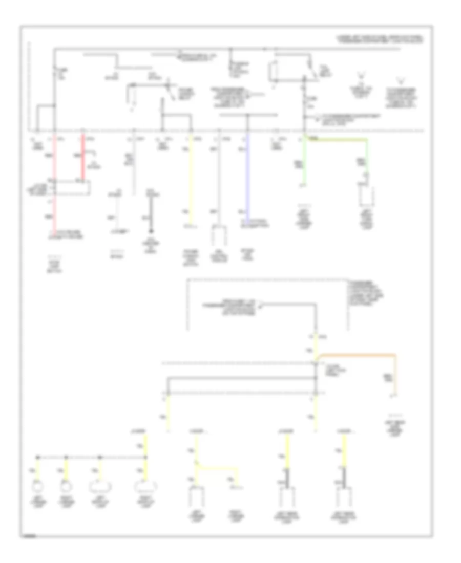
Power Distribution Wiring Diagram (4 of 7) for Hyundai Elantra GT 2002
 https://portal-diagnostov.com/license.html
Automotive Electricians Portal FZCO
Automotive Electricians Portal FZCO
https://portal-diagnostov.com/license.html
https://portal-diagnostov.com/license.html
Automotive Electricians Portal FZCO
Automotive Electricians Portal FZCOList of elements for Power Distribution Wiring Diagram (4 of 7) for Hyundai Elantra GT 2002:
- (not used)
- (under left side of dash, near kick panel) passenger compartment junction block
- (w/etacm)
- (w/o cruise)
- (w/tacm)
- (with cruise)
- 4 door
- 5 door
- Drl control module
- Etacm
- Etacm (or tacm)
- From fuse 20, 10a (diagram 6 of 7)
- From fuse 7, 10a passenger compartment s junction block (on top of page)
- From passenger compartment junction block fuse 15, 15a (diagram 3 of 7)
- Fuse 10a
- Fuse 15a
- Fusible link (p/wdw) 30a
- G12 (center of dash)
- I/p-b
- I/p-d
- I/p-f
- I/p-g
- I/p-h
- I/p-j
- J/c m36 (left side of dash)
- J/c m45 (left kick panel)
- Left back-up lamp
- Left front side marker lamp
- Left front turn signal lamp
- Left license lamp
- Left rear combination lamp
- Left rear side marker lamp
- M25-1
- Nca
- Passenger compartment junction block (under left side of dash, near kick panel)
- Power window main switch
- Power window relay
- Red
- Right back-up lamp
- Right license lamp
- Stop lamp switch
- Tail lamp relay
- To fuse 6, 10a (diagram 5 of 7)
- To passenger compartment junction block (pin 10, i/p-d)
- To passenger compartment junction block fuse 25, 15a (diagram 6 of 7)
- W/ etacm
- W/o etacm
Power Distribution Wiring Diagram (5 of 7) for Hyundai Elantra GT 2002
 https://portal-diagnostov.com/license.html
Automotive Electricians Portal FZCO
Automotive Electricians Portal FZCO
https://portal-diagnostov.com/license.html
https://portal-diagnostov.com/license.html
Automotive Electricians Portal FZCO
Automotive Electricians Portal FZCOList of elements for Power Distribution Wiring Diagram (5 of 7) for Hyundai Elantra GT 2002:
- (not used)
- (w/o trip)
- (w/trip)
- 4 door
- 5 door
- A/c control module
- A/t shift lever
- Audio
- Automatic a/c
- Cigarette lighter
- Digital clock
- Diode z02 (taped inside main wire harness, lower left side of dash)
- Drl control module
- Engine compartment relay & fuse box (in left front corner of engine compartment, behind battery)
- From tail lamp relay h (diagram 4 of 7)
- Front fog lamp relay
- Fuse 6 10a
- Glove box lamp
- Hazard switch
- I/p-b
- I/p-c
- I/p-d
- I/p-g
- I/p-j
- Instrument cluster
- J/c e61
- J/c m08 (lower left side of dash)
- Left rear power window switch
- M09-3
- M10-2
- M16
- M19-1
- M20
- Manual a/c
- Nca
- Passenger compartment junction block (under left side of dash, near kick panel)
- Pnk
- Power window main switch
- Rear wiper & washer switch
- Red
- Rheostat
- Right front power window switch
- Right front side marker lamp
- Right front turn signal lamp
- Right rear combination lamp
- Right rear power window switch
- Right rear side marker lamp
- Short connector
- Tcs switch
Power Distribution Wiring Diagram (6 of 7) for Hyundai Elantra GT 2002
 https://portal-diagnostov.com/license.html
Automotive Electricians Portal FZCO
Automotive Electricians Portal FZCO
https://portal-diagnostov.com/license.html
https://portal-diagnostov.com/license.html
Automotive Electricians Portal FZCO
Automotive Electricians Portal FZCOList of elements for Power Distribution Wiring Diagram (6 of 7) for Hyundai Elantra GT 2002:
- (auto a/c)
- (diagram 1 of 7)
- (diagram 4 of 7)
- (etacm)
- (manual a/c)
- (not used)
- (tacm)
- (under left side of dash, near kick panel) passenger compartment junction block
- (w/o etacm)
- (w/o trip)
- (w/trip)
- 4 door
- 5 door
- A/c control module
- A/c control module (auto a/c)
- A/c control module (manual a/c)
- Aqs sensor (auto a/c)
- Audio
- Auto a/c
- Blower relay
- Data link connector
- Digital clock
- Door
- Drl control module
- Ec03
- Engine compartment relay & fuse box (in left front corner of engine compartment, behind battery)
- Etacm (or tacm)
- From ignition switch (cavity 3) e
- From tail lamp relay i
- Front & rear washer motor
- Front washer motor
- Front wiper motor
- Fuse 10a
- Fuse 15a
- Fuse 20a
- Headlamp relay (high)
- Headlamp relay (low)
- I/p-b
- I/p-c
- I/p-d
- I/p-e
- I/p-g
- I/p-j
- Ignition key illumination & door warning switch
- Instrument cluster
- J/c e56
- J/c e61
- J/c m33 (left side of dash)
- J/c m36 (left side of dash)
- J/c m45 (left kick panel)
- Left front door lamp
- M09-1
- M10-2
- M19-1
- M20
- M25-1
- M26
- Manual a/c
- Map lamp
- Mode switch (manual a/c)
- Multi- purpose check connector
- Nca
- Overhead console assembly
- Passenger compartment junction block (under left side of dash, near kick panel)
- Pnk
- Power connector
- Rear intermittent wiper relay
- Rear wiper motor
- Red
- Right front door lamp
- Room lamp
- Sunroof relay
- Temperature switch (manual a/c)
- To power window relay (diagram 4 of 7)
- Trunk room lamp (or luggage lamp)
- W/ etacm)
- W/o sunroof
- Wiper motor relay
- With sunroof
Power Distribution Wiring Diagram (7 of 7) for Hyundai Elantra GT 2002
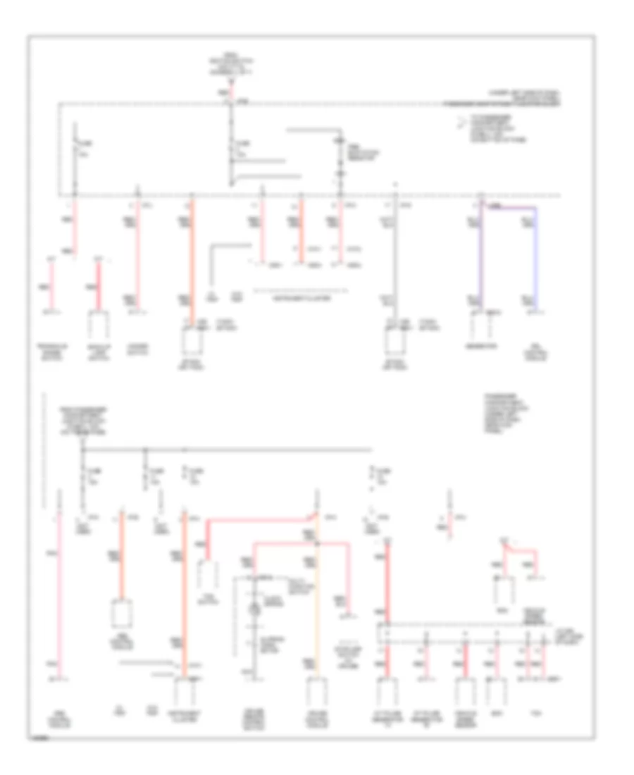 https://portal-diagnostov.com/license.html
Automotive Electricians Portal FZCO
Automotive Electricians Portal FZCO
https://portal-diagnostov.com/license.html
https://portal-diagnostov.com/license.html
Automotive Electricians Portal FZCO
Automotive Electricians Portal FZCOList of elements for Power Distribution Wiring Diagram (7 of 7) for Hyundai Elantra GT 2002:
- (etacm)
- (not used)
- (tacm)
- (under left side of dash, near kick panel) passenger compartment junction block
- A/t
- A/t pulse generator "a"
- A/t pulse generator "b"
- Abs control module
- Back-up lamp switch
- C86-1
- Clock spring
- Cruise control module
- Cruise remote control switch
- Drl control module
- E20-2
- Ecm
- Etacm (or tacm)
- From ignition switch (cavity 6) (diagram 1 of 7)
- From passenger compartment junction block (fuse 2, 10a) (on top of page)
- Fuse 10a
- Fuse 15a
- Generator
- Hazard switch
- I/p-b
- I/p-e
- I/p-g
- I/p-h
- I/p-j
- I/p-k
- Instrument cluster
- J/c c92 (left side of dash)
- M/t
- M01-3
- M09-1
- M09-2
- M09-3
- M10-1
- M10-2
- M25-1
- M26
- Multi- function switch
- Nca
- Passenger compartment junction block (under left side of dash, near kick panel)
- Pnk
- Pre- excitation resistor
- Red
- Slipring conn- ector
- Srs control module
- Stoplamp switch (w/ cruise)
- Tcm
- Tcs switch
- To passenger compartment junction block (fuse 3, 15a) (on bottom of page)
- Transaxle range switch
- Vehicle speed sensor
- W/ trip
- W/o trip
POWER DOOR LOCKS
Power Door Lock Wiring Diagram for Hyundai Elantra GT 2002
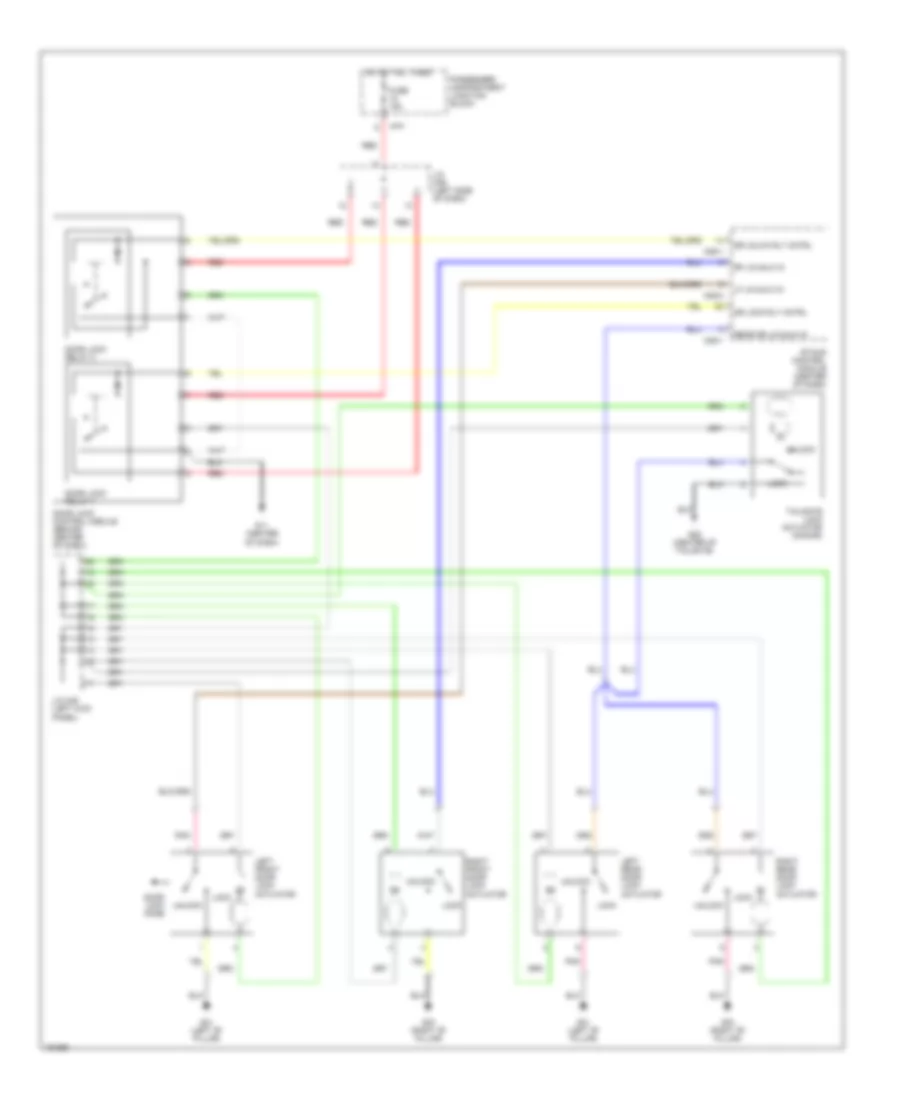 https://portal-diagnostov.com/license.html
Automotive Electricians Portal FZCO
Automotive Electricians Portal FZCO
https://portal-diagnostov.com/license.html
https://portal-diagnostov.com/license.html
Automotive Electricians Portal FZCO
Automotive Electricians Portal FZCOList of elements for Power Door Lock Wiring Diagram for Hyundai Elantra GT 2002:
- Door lock control module (behind center of dash)
- Door lock knob
- Door lock relay 1
- Door lock relay 2
- Dr lock rly cntrl
- Dr unlck rly cntrl
- Etacs control module (center of dash)
- Fuse 15a
- G01 (left "b" pillar)
- G03 (right "b" pillar)
- G11 (center of dash)
- G28 (center of tailgate)
- Hot at all times
- I/p-f
- J/c m36 (left side of dash)
- J/c m45 (left kick panel)
- Left front door lock actuator
- Left rear door lock actuator
- Lf lk/unlk in
- Lock
- M25-1
- M25-2
- Passenger compartment junction block
- Pnk
- Rear dr lk/unlk in
- Red
- Rf lk/unlk in
- Right front door lock actuator
- Right rear door lock actuator
- Tailgate lock actuator (5-door)
- Unlock
POWER MIRRORS
Power Mirror Wiring Diagram for Hyundai Elantra GT 2002
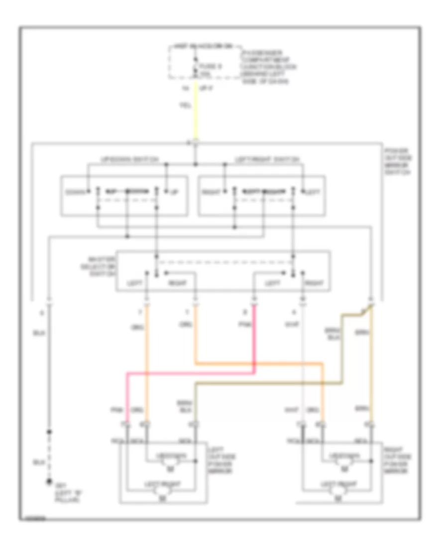 https://portal-diagnostov.com/license.html
Automotive Electricians Portal FZCO
Automotive Electricians Portal FZCO
https://portal-diagnostov.com/license.html
https://portal-diagnostov.com/license.html
Automotive Electricians Portal FZCO
Automotive Electricians Portal FZCOList of elements for Power Mirror Wiring Diagram for Hyundai Elantra GT 2002:
- Down
- Fuse 9 10a
- G01 (left "b" pillar)
- Hot in acc or on
- I/p-f
- Left
- Left outside power mirror
- Left/right
- Left/right switch
- Master selector switch
- Nca
- Passenger compartment junction block (behind left side of dash)
- Pnk
- Power outside mirror switch
- Right
- Right outside power mirror
- Up/down
- Up/down switch
POWER TOP/SUNROOF
Power Top/Sunroof Wiring Diagrams for Hyundai Elantra GT 2002
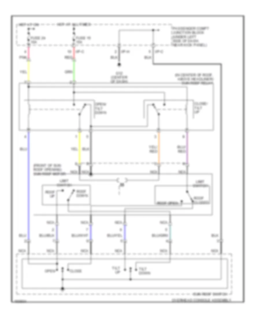 https://portal-diagnostov.com/license.html
Automotive Electricians Portal FZCO
Automotive Electricians Portal FZCO
https://portal-diagnostov.com/license.html
https://portal-diagnostov.com/license.html
Automotive Electricians Portal FZCO
Automotive Electricians Portal FZCOList of elements for Power Top/Sunroof Wiring Diagrams for Hyundai Elantra GT 2002:
- (front of sun roof opening) sun roof motor
- (in center of roof, above headliner) sun roof relay
- Close
- Close/ tilt up
- Fuse 15 15a
- Fuse 24 10a
- G12 (center of dash)
- Hot at all times
- Hot at on
- I/p-c
- I/p-h
- Limit switch
- Nca
- Open
- Open/ tilt down
- Overhead console assembly
- Passenger compt junction block (under left side of dash, near kick panel)
- Pnk
- Red
- Roof closed
- Roof down
- Roof open
- Roof up
- Sun roof switch
- Tilt down
- Tilt up
POWER WINDOWS
Power Window Wiring Diagram for Hyundai Elantra GT 2002
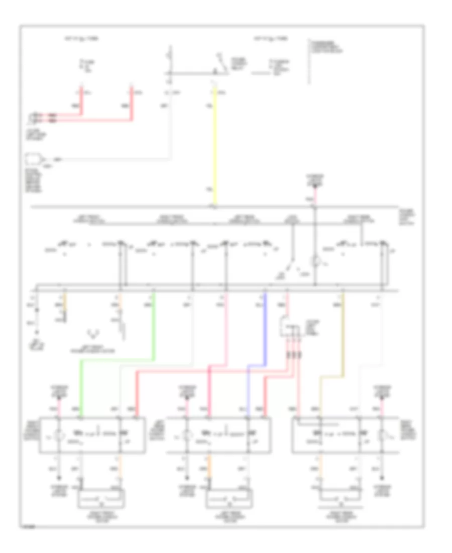 https://portal-diagnostov.com/license.html
Automotive Electricians Portal FZCO
Automotive Electricians Portal FZCO
https://portal-diagnostov.com/license.html
https://portal-diagnostov.com/license.html
Automotive Electricians Portal FZCO
Automotive Electricians Portal FZCOList of elements for Power Window Wiring Diagram for Hyundai Elantra GT 2002:
- Down
- Etacs control module (behind center of dash)
- Fuse 15a
- Fusible link (p/wdw) 30a
- G01 (left "b" pillar)
- Hot at all times
- I/p-d
- I/p-f
- I/p-g
- I/p-j
- Ill
- Interior lights system
- J/c m36 (left side of dash)
- J/c m45 (left kick panel)
- Left front power window motor
- Left front window switch
- Left rear power window motor
- Left rear power window switch
- Left rear window switch
- Lock
- Lock switch
- M25-1
- Nca
- Off
- Off down
- Passenger compartment junction block
- Pnk
- Power window main switch
- Power window relay
- Red
- Right front power window motor
- Right front power window switch
- Right front window switch
- Right rear power window motor
- Right rear power window switch
- Right rear window switch
- Un- lock
RADIO
Radio Wiring Diagrams for Hyundai Elantra GT 2002
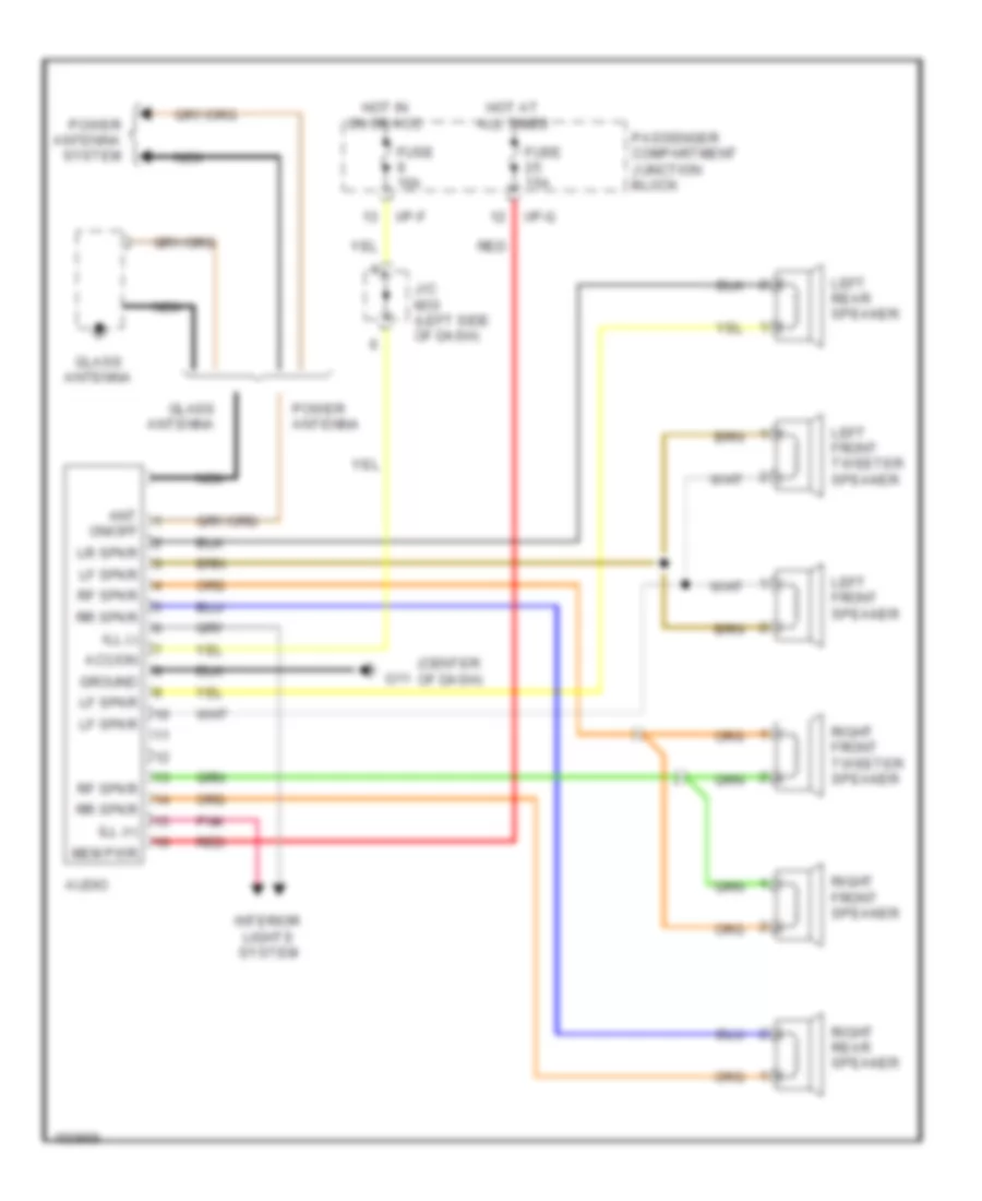 https://portal-diagnostov.com/license.html
Automotive Electricians Portal FZCO
Automotive Electricians Portal FZCO
https://portal-diagnostov.com/license.html
https://portal-diagnostov.com/license.html
Automotive Electricians Portal FZCO
Automotive Electricians Portal FZCOList of elements for Radio Wiring Diagrams for Hyundai Elantra GT 2002:
- (center of dash)
- Acc/on
- Ant
- Audio
- Fuse 10a
- Fuse 15a
- G11
- Glass antenna
- Ground
- Hot at all times
- Hot in on or acc
- I/p-f
- I/p-g
- Ill (+)
- Ill (-)
- Interior lights system
- J/c m33 (left side of dash)
- Left front speaker
- Left front tweeter speaker
- Left rear speaker
- Lf spkr
- Lr spkr
- Mem pwr
- Nca
- On/off
- Passenger compartment junction block
- Pnk
- Power antenna
- Power antenna system
- Red
- Rf spkr
- Right front speaker
- Right front tweeter speaker
- Right rear speaker
- Rr spkr
STARTING/CHARGING
Charging Wiring Diagram for Hyundai Elantra GT 2002
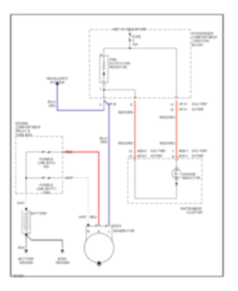 https://portal-diagnostov.com/license.html
Automotive Electricians Portal FZCO
Automotive Electricians Portal FZCO
https://portal-diagnostov.com/license.html
https://portal-diagnostov.com/license.html
Automotive Electricians Portal FZCO
Automotive Electricians Portal FZCOList of elements for Charging Wiring Diagram for Hyundai Elantra GT 2002:
- Battery
- Battery ground
- Body ground
- Charge indicator
- E20-2
- Engine compartment relay & fuse box
- Fuse 10a
- Fusible link (batt) 100a
- Fusible link (ecu) 20a
- Generator
- Headlights system
- Hot at on & start
- I/p-b
- I/p-h
- Instrument cluster
- M09-1
- M09-2
- M10-1
- M10-2
- Passenger compartment junction block
- Pre- excitation resistor
- Red
- W/o trip
- W/trip
Starting Wiring Diagram for Hyundai Elantra GT 2002
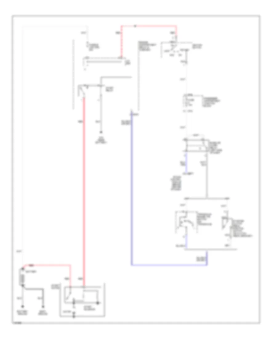 https://portal-diagnostov.com/license.html
Automotive Electricians Portal FZCO
Automotive Electricians Portal FZCO
https://portal-diagnostov.com/license.html
https://portal-diagnostov.com/license.html
Automotive Electricians Portal FZCO
Automotive Electricians Portal FZCOList of elements for Starting Wiring Diagram for Hyundai Elantra GT 2002:
- A/t
- Acc
- Battery
- Battery ground
- Body ground
- Burglar alarm relay (left side of dash)
- Ec03
- Engine compartment relay & fuse box
- Etacs control module (behind center of dash)
- Fuse 10a
- Fusible link (ign) 30a
- G15 (near battery)
- I/p-e
- I/p-g
- Ignition switch
- J/c e55
- Lock
- M/t
- M25-3
- Motor
- N d
- Nca
- Passenger compartment junction block
- Red
- Start
- Start motor
- Start relay
- Start solenoid
- Starter clutch pedal position switch (on clutch pedal bracket)
- Transaxle range (tr) switch (on transaxle)
SUPPLEMENTAL RESTRAINTS
Supplemental Restraint Wiring Diagram for Hyundai Elantra GT 2002
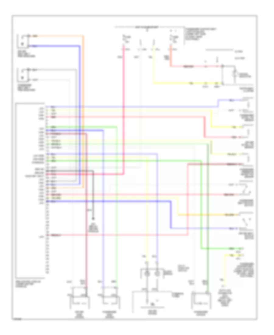 https://portal-diagnostov.com/license.html
Automotive Electricians Portal FZCO
Automotive Electricians Portal FZCO
https://portal-diagnostov.com/license.html
https://portal-diagnostov.com/license.html
Automotive Electricians Portal FZCO
Automotive Electricians Portal FZCOList of elements for Supplemental Restraint Wiring Diagram for Hyundai Elantra GT 2002:
- Air bag indicator
- Clock- spring
- Data link connector (dlc) (partial) (below left side of dash)
- Diagnosis
- Driver air bag
- Driver satellite sensor
- Driver seat belt pretensioner
- Driver seat buckle switch
- Driver side air bag
- Fuse 10a
- Fuse 15a
- G27 (below center console)
- Ground
- High
- High side
- Hot in on or start
- I/p-h
- I/p-j
- I/p-k
- Instrument cluster
- Low
- Low side
- M09-1
- M10-1
- Multi- function switch
- Nca
- On/start input
- Passenger air bag
- Passenger compartment junction block (under left side of dash, near kick panel)
- Passenger presence detection sensor
- Passenger satellite sensor
- Passenger seat belt pretensioner
- Passenger seat buckle switch
- Passenger side air bag
- Pnk
- Red
- Srs control module (under center console)
- Srs ind
- Steering wheel
- W/o trip
- W/trip
TRANSMISSION
A/T Wiring Diagram for Hyundai Elantra GT 2002
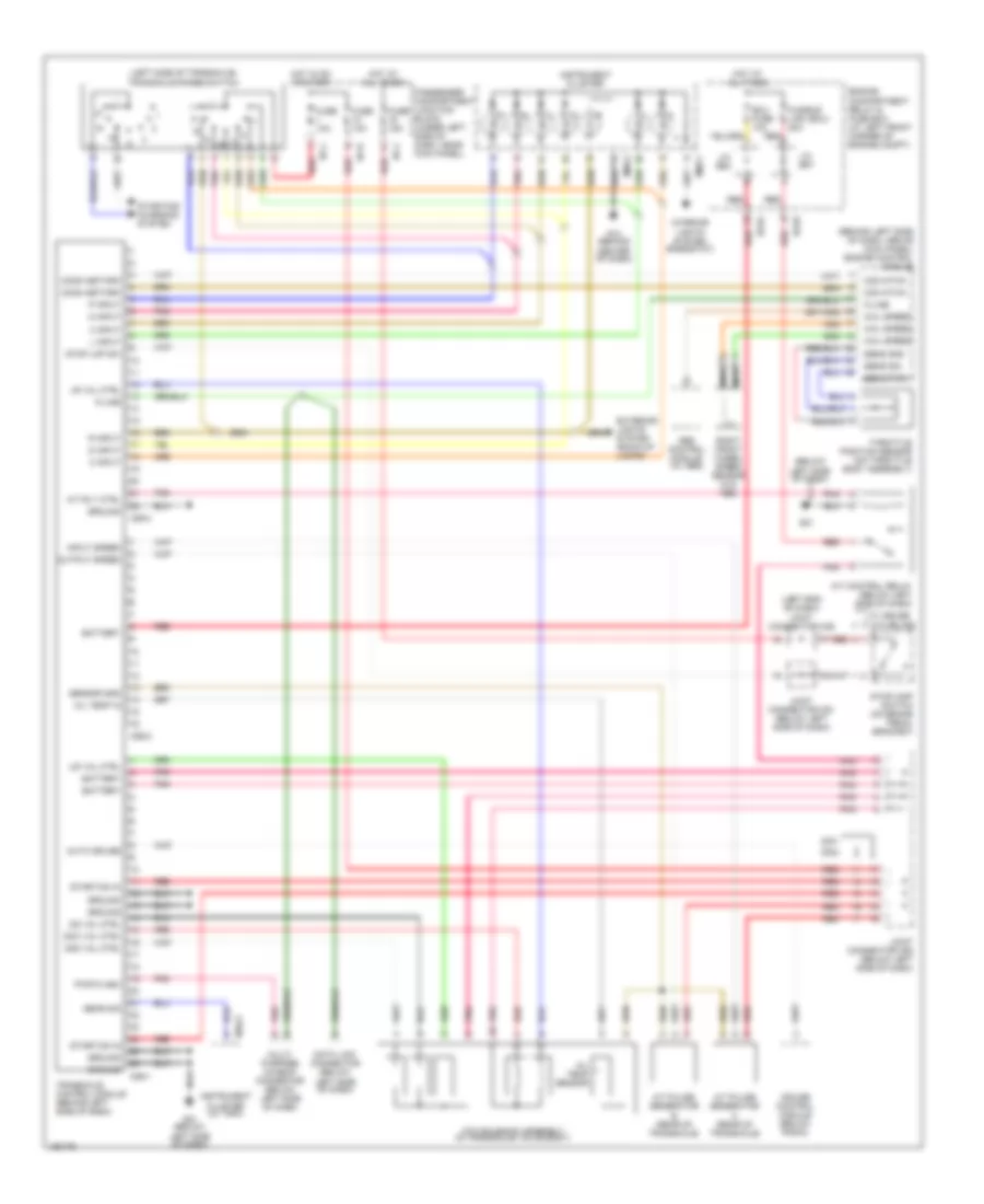 https://portal-diagnostov.com/license.html
Automotive Electricians Portal FZCO
Automotive Electricians Portal FZCO
https://portal-diagnostov.com/license.html
https://portal-diagnostov.com/license.html
Automotive Electricians Portal FZCO
Automotive Electricians Portal FZCOList of elements for A/T Wiring Diagram for Hyundai Elantra GT 2002:
- (behind left side of dash, above kick panel) engine control module
- (below
- (left end of dash) joint connector m36
- (left side of transaxle) transaxle range switch
- 2 input
- 2nd val ctrl
- 3 input
- A/t control relay (below left side of dash)
- A/t pulse generator a (rear of transaxle)
- A/t pulse generator b (rear of transaxle)
- A/t rly ctrl
- Abs control module (w/ abs)
- Atm solenoid assembly (in transaxle valve body)
- Auto cruise
- Battery
- C86-1
- C86-2
- C86-3
- Com ntwk
- Comm netwrk
- Cruise control module (below radio)
- D input
- Data link connector (below
- Dcc val ctrl
- Ec03
- Ec04
- Ecu fuse 10a
- Engine compartment relay & fuse box (at left front corner of engine compt)
- Exterior lights system (back-up lamps)
- Fuse 10a
- Fuse 15a
- Fusible link (ecu) 20a
- G14 (behind center of dash)
- G21
- G21 (below left side of dash)
- Gear sig
- Ground
- Hot at all times
- Hot in on or start
- I/p-h
- I/p-j
- Input speed
- Instrument cluster
- Instrument cluster (w/ trip)
- Interior lights system (rheostat)
- J/c e57
- J/c e62
- Joint connector c91 (below left side of dash)
- Joint connector c92 (below left side of dash)
- K-line
- L input
- Left side of dash)
- Lr val ctrl
- M09-1
- M09-2
- M10-2
- Multi- purpose chaeck connector (below left side of dash)
- N input
- Nca
- Od val ctrl
- Oil temp in
- Oil temp sensor
- Output speed
- P input
- Passenger compartment junction block (under left side of dash, near kick panel)
- Pnk
- Pwr flash
- R input
- Red
- Right front wheel speed sensor (w/o abs)
- Sens gnd
- Sens pwr
- Sens sig
- Sensor gnd
- Start/on in
- Starting/ charging system
- Stop lmp sw
- Stoplamp switch (on brake pedal bracket)
- Throttle position sensor (on throttle body assembly)
- Transaxle control module (behind left side of dash)
- Ud val ctrl
- W/ cruise
- W/o cruise
- Whl speed
WARNING SYSTEMS
Warning System Wiring Diagrams for Hyundai Elantra GT 2002
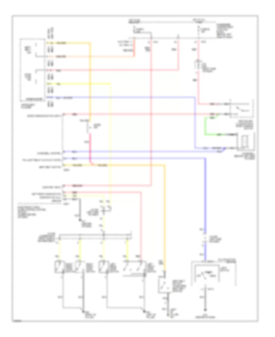 https://portal-diagnostov.com/license.html
Automotive Electricians Portal FZCO
Automotive Electricians Portal FZCO
https://portal-diagnostov.com/license.html
https://portal-diagnostov.com/license.html
Automotive Electricians Portal FZCO
Automotive Electricians Portal FZCOList of elements for Warning System Wiring Diagrams for Hyundai Elantra GT 2002:
- (left "b" pillar) g01
- (w/ trip)
- (w/o trip)
- Chime bell (behind left side of dash)
- Chime bell control
- Diode z08
- Door ajar ind
- Door switch (all)
- Door warning switch input
- Electronic time & alarm control system (etacm) (under center of dash)
- Fuse 2 10a
- Fuse 25 15a
- G01 (left "b" pillar)
- G03 (right "b" pillar)
- G11 (center of dash)
- G14 (center of dash)
- Ground
- Head
- Hot at all times
- Hot in on or start
- I/p-g
- I/p-h
- Ignition key illumination & door warning switch
- Instrument cluster
- J/c m33 (left side of dash)
- J/c m33 (right side of dash)
- J/c m36 (left side of dash)
- J/c m46 (under right front side of driver's seat)
- Left front door switch
- Left rear door switch
- Light switch
- M01-2
- M09-1
- M09-3
- M10-1
- M10-2
- M25-1
- M25-2
- Multifunction switch
- Nca
- Off
- On/start input
- Park
- Passenger compartment junction block (behind left side of dash)
- Pnk
- Red
- Right front door switch
- Right rear door switch
- Seat belt ind
- Seat belt switch
- Seat belt switch (in driver's seat belt buckle)
- Speedometer
- Taillight relay auto cut cntrl
WIPER/WASHER
Front Washer/Wiper Wiring Diagram, 5 Door for Hyundai Elantra GT 2002
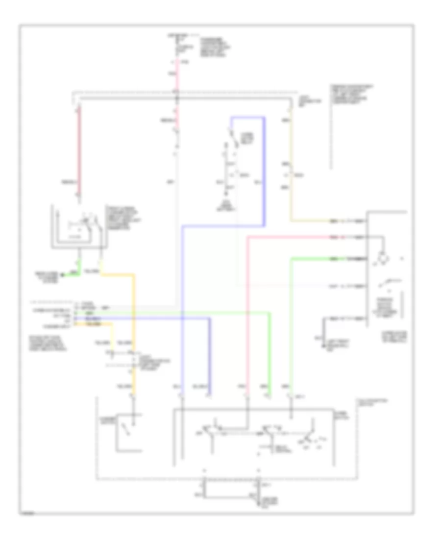 https://portal-diagnostov.com/license.html
Automotive Electricians Portal FZCO
Automotive Electricians Portal FZCO
https://portal-diagnostov.com/license.html
https://portal-diagnostov.com/license.html
Automotive Electricians Portal FZCO
Automotive Electricians Portal FZCOList of elements for Front Washer/Wiper Wiring Diagram, 5 Door for Hyundai Elantra GT 2002:
- (center of dash) g12
- (etacs)
- (left front frame rail) g23
- (tacs)
- Delay control
- Ec03
- Engine compartment relay & fuse box (at left front corner of engine compartment)
- Etacs (or tacs) control module (under center of dash, below radio)
- Front & rear washer motor (below right front headlight in washer reservoir)
- Fuse 22 20a
- G15 (near battery)
- Hot at on
- I/p-b
- Int
- Int (time)
- Joint connector e61
- Joint connector m33 (left side of dash)
- M01-1
- Multifunction switch
- Nca
- Off
- Parking switch (shown with wipers at rest)
- Passenger compartment junction block (behind left side of dash)
- Pnk
- Rear wiper & washer system
- Washer input
- Washer switch
- Wiper motor (on left side of firewall)
- Wiper motor relay
- Wiper switch
Rear Washer/Wiper Wiring Diagram, 5 Door for Hyundai Elantra GT 2002
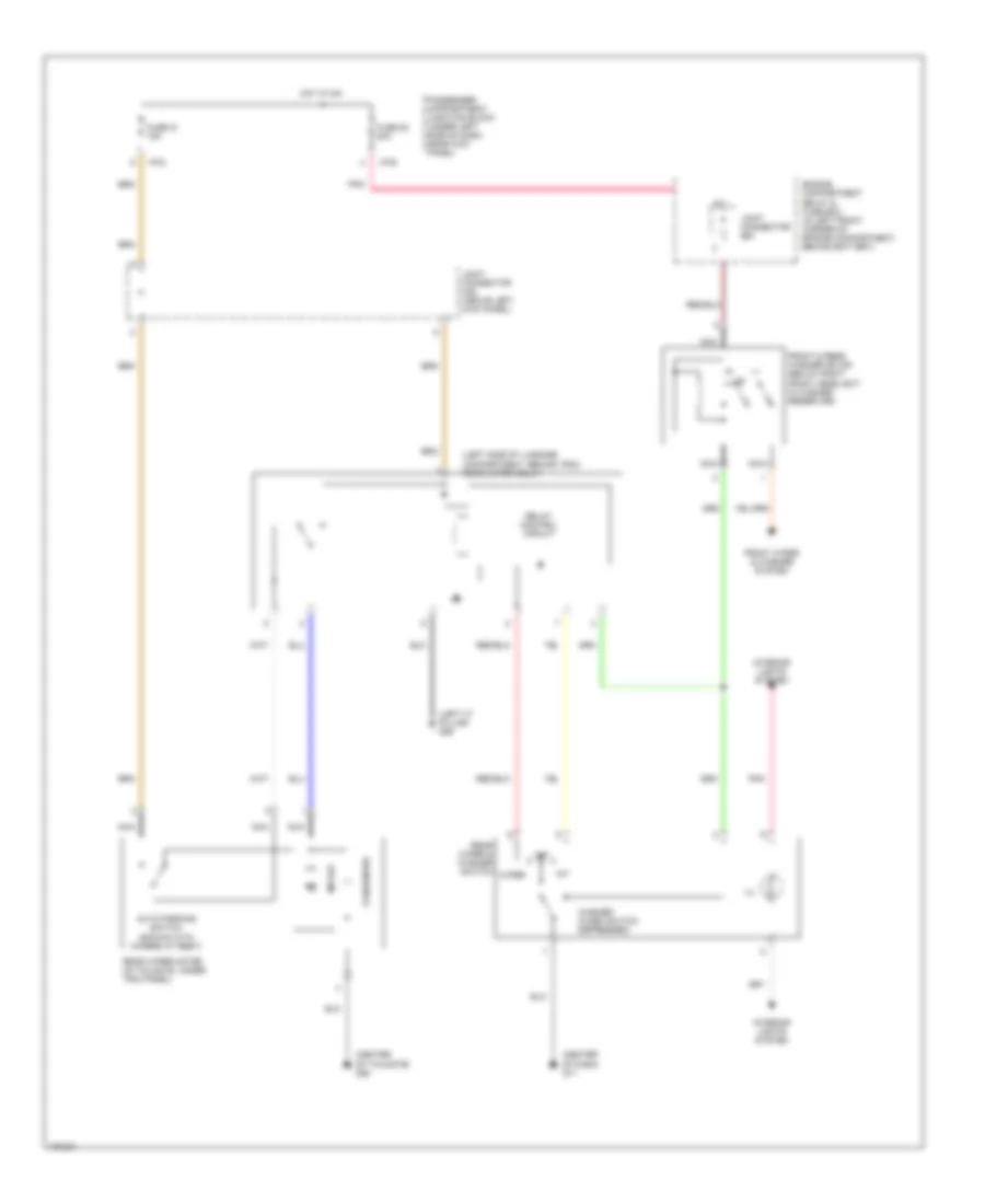 https://portal-diagnostov.com/license.html
Automotive Electricians Portal FZCO
Automotive Electricians Portal FZCO
https://portal-diagnostov.com/license.html
https://portal-diagnostov.com/license.html
Automotive Electricians Portal FZCO
Automotive Electricians Portal FZCOList of elements for Rear Washer/Wiper Wiring Diagram, 5 Door for Hyundai Elantra GT 2002:
- (center of dash) g11
- (center of tailgate) g28
- (left "c" pillar) g06
- (left side of luggage compartment, behind trim) rear wiper relay
- Auto parking switch (shown with wipers at rest)
- Condenser
- Engine compartment relay & fuse box (in left front corner of engine compartment, behind battery)
- Front & rear washer motor (below right front headlight in washer reservoir)
- Front wiper & washer system
- Fuse 21 15a
- Fuse 22 20a
- Hot at on
- I/p-b
- I/p-d
- Ill.
- Int
- Interior lights system
- Joint connector e61
- Joint connector m45 (above left kick panel)
- Motor
- Nca
- Off
- Passenger compartment junction block (under left side of dash, near kick panel)
- Pnk
- Rear wiper & washer switch
- Rear wiper motor (in tailgate, under trim panel)
- Relay control circuit
- Washer (when switch depressed)
- Wiper
Wiper/Washer Wiring Diagram, 4 Door for Hyundai Elantra GT 2002
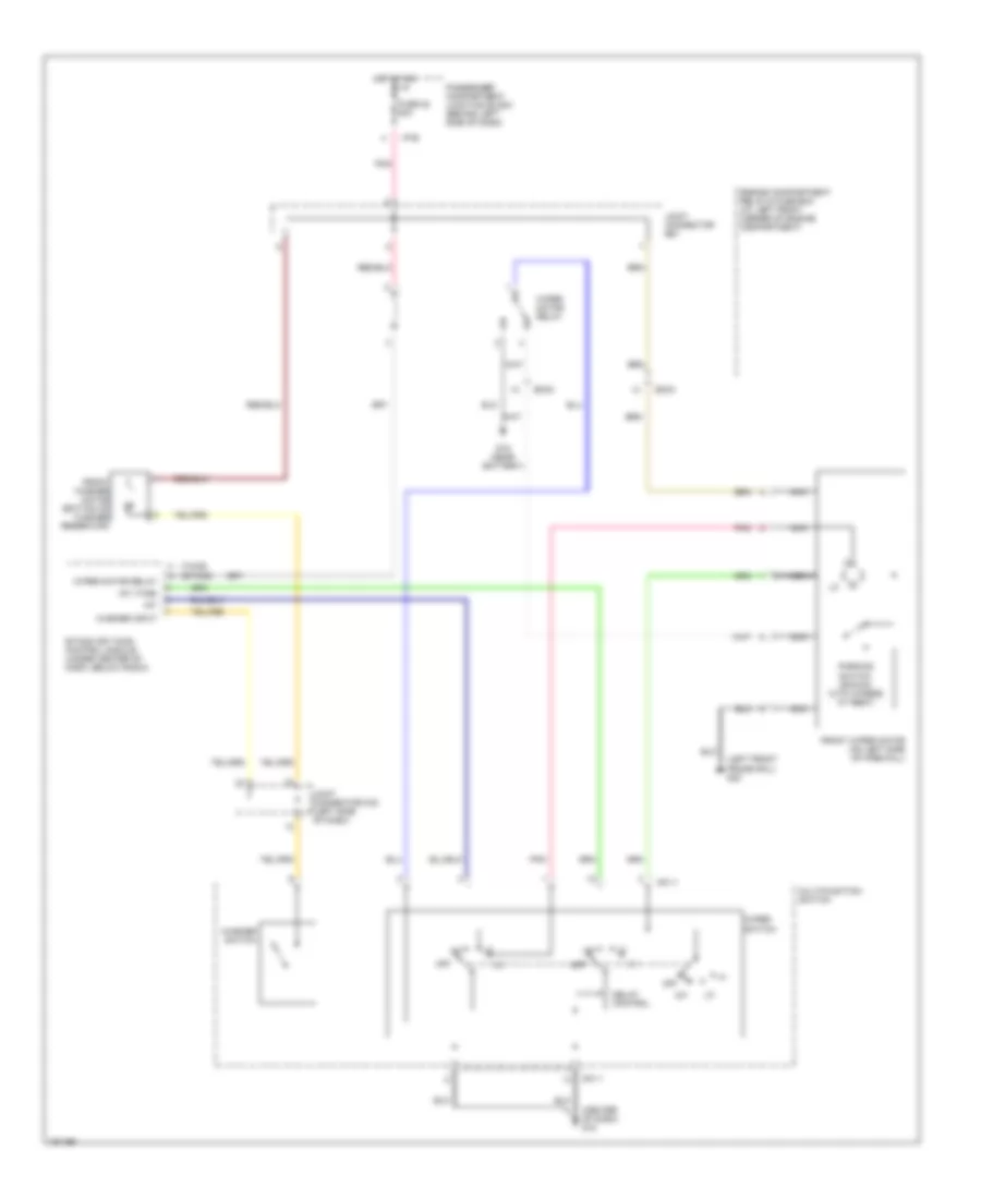 https://portal-diagnostov.com/license.html
Automotive Electricians Portal FZCO
Automotive Electricians Portal FZCO
https://portal-diagnostov.com/license.html
https://portal-diagnostov.com/license.html
Automotive Electricians Portal FZCO
Automotive Electricians Portal FZCOList of elements for Wiper/Washer Wiring Diagram, 4 Door for Hyundai Elantra GT 2002:
- (center of dash) g12
- (etacs)
- (left front frame rail) g23
- (tacs)
- Delay control
- Ec03
- Engine compartment relay & fuse box (at left front corner of engine compartment)
- Etacs (or tacs) control module (under center of dash, below radio)
- Front washer motor (bottom of washer reservoir)
- Front wiper motor (on left side of firewall)
- Fuse 22 20a
- G15 (near battery)
- Hot at on
- I/p-b
- Int
- Int (time)
- Joint connector e61
- Joint connector m33 (left side of dash)
- M01-1
- Multifunction switch
- Nca
- Off
- Parking switch (shown with wipers at rest)
- Passenger compartment junction block (behind left side of dash)
- Pnk
- Washer input
- Washer switch
- Wiper motor relay
- Wiper switch

 Čeština
 Dansk
Dansk Deutsch
 Ελληνικά
 English
 English
 Español
 Suomi
Suomi Français
 Français
 עברית
עברית Hrvatski
 Magyar
 Italiano
 한국어
한국어 Nederlands
 Polski
 Português
 Português
 Română
 Русский
 Slovenčina
 Slovenščina
 Svenska
 Türkçe
 中文 (中国)
