AIR CONDITIONING
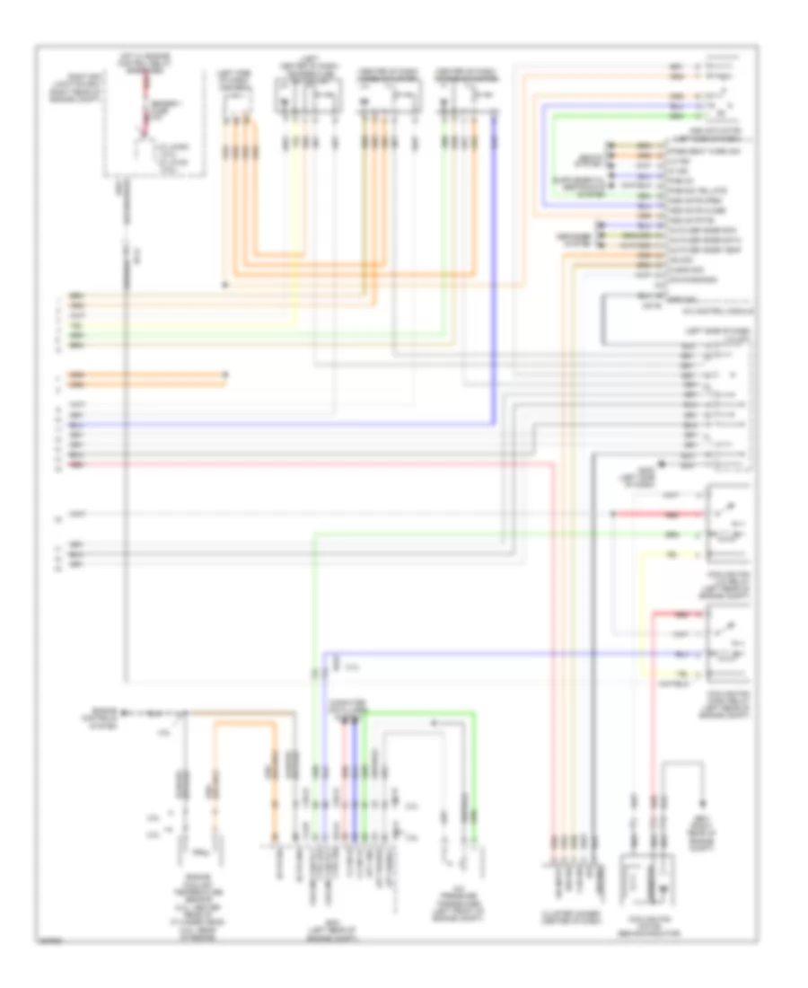
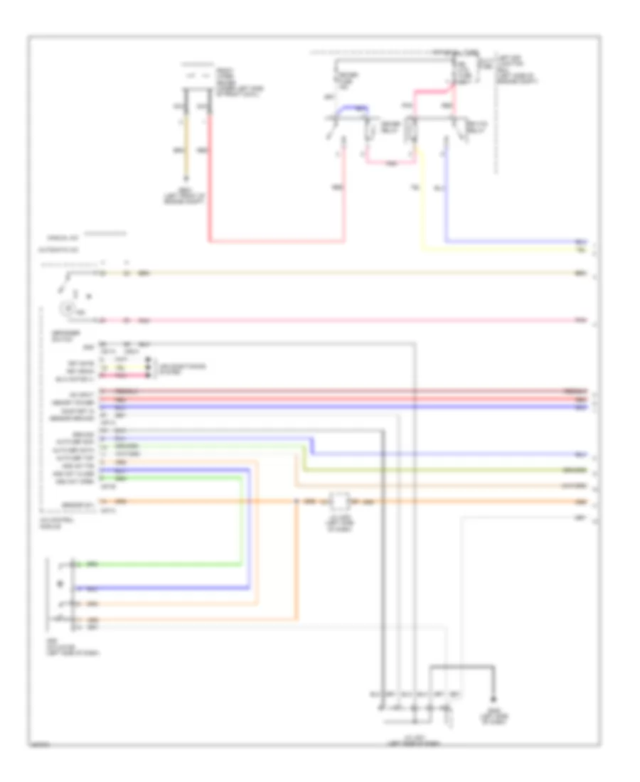
Automatic A/C Wiring Diagram (1 of 2) for Hyundai Genesis Coupe 2.0T Premium 2013
 https://portal-diagnostov.com/license.html
Automotive Electricians Portal FZCO
Automotive Electricians Portal FZCO
https://portal-diagnostov.com/license.html
https://portal-diagnostov.com/license.html
Automotive Electricians Portal FZCO
Automotive Electricians Portal FZCO
List of elements for Automatic A/C Wiring Diagram (1 of 2) for Hyundai Genesis Coupe 2.0T Premium 2013:
- A/c control module
- Alt fuse 150a
- Ambient temperature sensor (center of radiator support)
- Auto light & photo sensor (top center of dash)
- Blower fuse 40a
- Blower fuse 7.5a
- Blower motor (+)
- Blower motor (right side of dash)
- Blower relay
- C-can hi
- C-can lo
- Computer data lines system
- Cooling fan fuse 60a
- Defogger ind
- Defogger sw
- Defogger system
- Dr seat war sw
- Ec21
- Ecv ground
- Ecv power
- Ee11
- Electrical control valve
- Electronic a/c compressor (lower left front of engine)
- Em21
- Em51
- Evap snsr
- Evaporator sensor (center of dash)
- Exterior lights system
- Fet (g)
- Fet drain
- Field effect transistor (center of dash)
- Gm04 (center of dash)
- Gnd
- High ind
- Hot at all times
- Hot in on
- Hot in on or start
- Hzrd sw
- I/p-a
- I/p-c
- I/p-d
- I/p-e
- Ill (+)
- Ill (-)
- In actr f/b
- In actr fre
- In actr rec
- Incar temperature sensor
- Interior lights system
- K line
- Leak current autocut device
- Left e/r junction box (left side of engine compt)
- Low ind
- M can high
- M can low
- M07-a
- Memory 1 fuse 10a
- Memory power
- Mode actr def
- Mode actr f/b
- Mode actr vent
- Module 2 fuse 7.5a
- Module 7 fuse 7.5a
- Multi fuse
- On input
- On/start input
- Photo sensor
- Photo snsr
- Pnk
- Red
- Seats system
- Smart junction box
- Snsr (5v)
- Snsr gnd
- Temp actr cool
- Temp actr f/b
- Temp actr warm
- Temp snsr in
- Temp snsr out
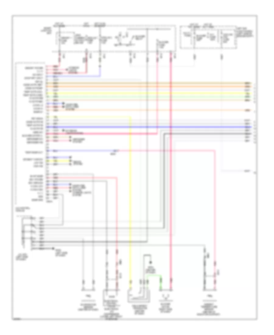
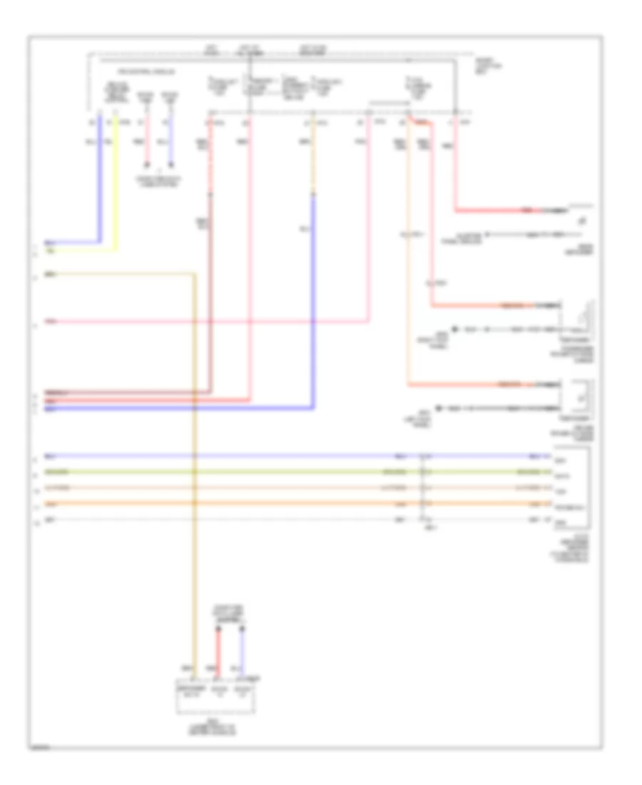
Automatic A/C Wiring Diagram (2 of 2) for Hyundai Genesis Coupe 2.0T Premium 2013
 https://portal-diagnostov.com/license.html
Automotive Electricians Portal FZCO
Automotive Electricians Portal FZCO
https://portal-diagnostov.com/license.html
https://portal-diagnostov.com/license.html
Automotive Electricians Portal FZCO
Automotive Electricians Portal FZCOList of elements for Automatic A/C Wiring Diagram (2 of 2) for Hyundai Genesis Coupe 2.0T Premium 2013:
- (2.0l)
- (3.8l)
- (center of dash) intake actuator
- (center of dash) mode actuator
- (left center of dash) temperature actuator
- (left side of dash) j/c jm01
- (left side of dash) j/c jm03
- 2.0l
- 3.8l
- A/c control module
- A/c pressure transducer (left front of engine compt)
- Ads actr close
- Ads actr f/b
- Ads actr open
- Ads actuator (left side of dash)
- Apt gnd
- Apt power
- Apt signal
- Auto def snsr data
- Auto def snsr sck
- Auto def snsr temp
- C-can hi
- C-can lo
- Chg-k
- Clean sig
- Clg-b
- Cln sig
- Cluster ionizer (center of dash)
- Computer data lines system
- Cooling fan (high) relay (left rear of engine compt)
- Cooling fan (lo) relay (left rear of engine compt)
- Cooling fan motor (behind radiator)
- Ctrl (hi) cooling fan rly
- Ctrl (lo) cooling fan rly
- Defogger system
- Dia
- Ec11
- Ec21
- Ecm (left rear of engine compt)
- Ects gnd
- Ects sig
- Elg-a
- Engine controls system
- Engine coolant temperature sensor (2.0l: center rear of cylinder head) (3.8l: rear of engine)
- Ge01 (right rear of engine compt)
- Gm02 (left side of dash)
- Ground
- Hi ind
- Hot w/ engine control relay energized
- Ion diagnosis
- Ion sig
- J/c jch83
- J/c jcl83
- Lo ind
- M07-b
- Nca
- On input
- Pab ig1
- Pab sig tellate
- Pass seat warm sw
- Pnk
- Red
- Resistor
- Right e/r junction box (right rear of engine compt)
- Seats system
- Sensor 1 fuse 10a
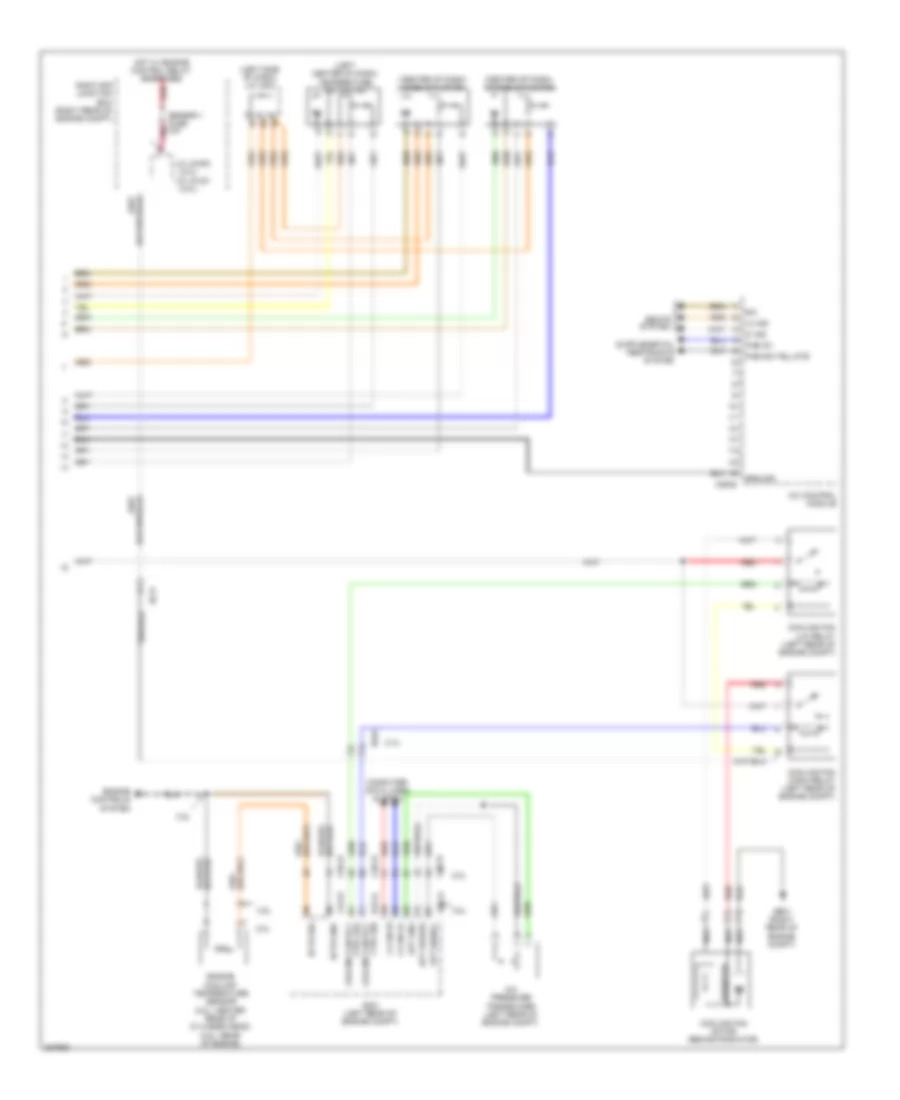
Manual A/C Wiring Diagram (1 of 2) for Hyundai Genesis Coupe 2.0T Premium 2013
 https://portal-diagnostov.com/license.html
Automotive Electricians Portal FZCO
Automotive Electricians Portal FZCO
https://portal-diagnostov.com/license.html
https://portal-diagnostov.com/license.html
Automotive Electricians Portal FZCO
Automotive Electricians Portal FZCOList of elements for Manual A/C Wiring Diagram (1 of 2) for Hyundai Genesis Coupe 2.0T Premium 2013:
- (left side of dash)
- A/c control module
- Alt fuse 150a
- Ambient temperature sensor (center of radiator support)
- Blower fuse 40a
- Blower fuse 7.5a
- Blower motor (+)
- Blower motor (right side of dash)
- Blower relay
- C-can hi
- C-can lo
- Computer data lines system
- Computer data lines system interior lights system
- Cooling fan fuse 60a
- Defogger ind
- Defogger sw
- Defogger system
- Dr seat war sw
- Ec21
- Ecv ground
- Ecv power
- Ee11
- Electrical control valve
- Electronic a/c compressor (lower left front of engine)
- Em21
- Em51
- Evap snsr
- Evaporator sensor (center of dash)
- Exterior lights system
- Fet (g)
- Fet drain
- Field effect transistor (center of dash)
- Gm02 (left side of dash)
- Gm04 (center of dash)
- Gnd
- High ind
- Hot at all times
- Hot in on
- Hot in on or start
- Hzrd sw
- I/p-a
- I/p-c
- I/p-d
- I/p-e
- Ill (+)
- Ill (-)
- In actr f/b
- In actr fre
- In actr rec
- Interior lights system
- J/c jm01
- Leak current autocut device
- Left e/r junction box (left side of engine compt)
- Low ind
- M can high
- M can low
- M06-a
- Memory 1 fuse 10a
- Memory power
- Mode actr def
- Mode actr f/b
- Mode actr vent
- Module 2 fuse 7.5a
- Module 7 fuse 7.5a
- Multi- fuse
- On input
- On/start input
- Pnk
- Red
- Seats system
- Smart junction box
- Snsr 5v
- Snsr gnd
- Temp actr cool
- Temp actr f/b
- Temp actr warm
- Temp snsr out
Manual A/C Wiring Diagram (2 of 2) for Hyundai Genesis Coupe 2.0T Premium 2013
 https://portal-diagnostov.com/license.html
Automotive Electricians Portal FZCO
Automotive Electricians Portal FZCO
https://portal-diagnostov.com/license.html
https://portal-diagnostov.com/license.html
Automotive Electricians Portal FZCO
Automotive Electricians Portal FZCOList of elements for Manual A/C Wiring Diagram (2 of 2) for Hyundai Genesis Coupe 2.0T Premium 2013:
- (2.0l)
- (3.8l)
- (center of dash) intake actuator
- (center of dash) mode actuator
- (left center of dash) temperature actuator
- (left side of dash) j/c jm03
- 2.0l
- 3.8l
- A/c control module
- A/c pressure transducer (left rear of engine compt)
- Apt gnd
- Apt power
- Apt signal
- C-can hi
- C-can lo
- Chg-k
- Clg-b
- Computer data lines system
- Cooling fan (high) relay (left rear of engine compt)
- Cooling fan (lo) relay (left rear of engine compt)
- Cooling fan motor (behind radiator)
- Ctrl (hi) cooling fan rly
- Ctrl (lo) cooling fan rly
- Ec11
- Ec21
- Ecm (left rear of engine compt)
- Ects gnd
- Ects sig
- Elg-a
- Engine controls system
- Engine coolant temperature sensor (2.0l: center rear of cylinder head) (3.8l: rear of engine)
- Ge01 (right rear of engine compt)
- Ground
- Hi ind
- Hot w/ engine control relay energized
- J/c jch83
- J/c jcl83
- Lo ind
- M06-b
- Nca
- Pab ig1
- Pab sig tellate
- Pnk
- Red
- Resistor
- Right e/r junction box (right rear of engine compt)
- Seats system
- Sensor 1 fuse 10a
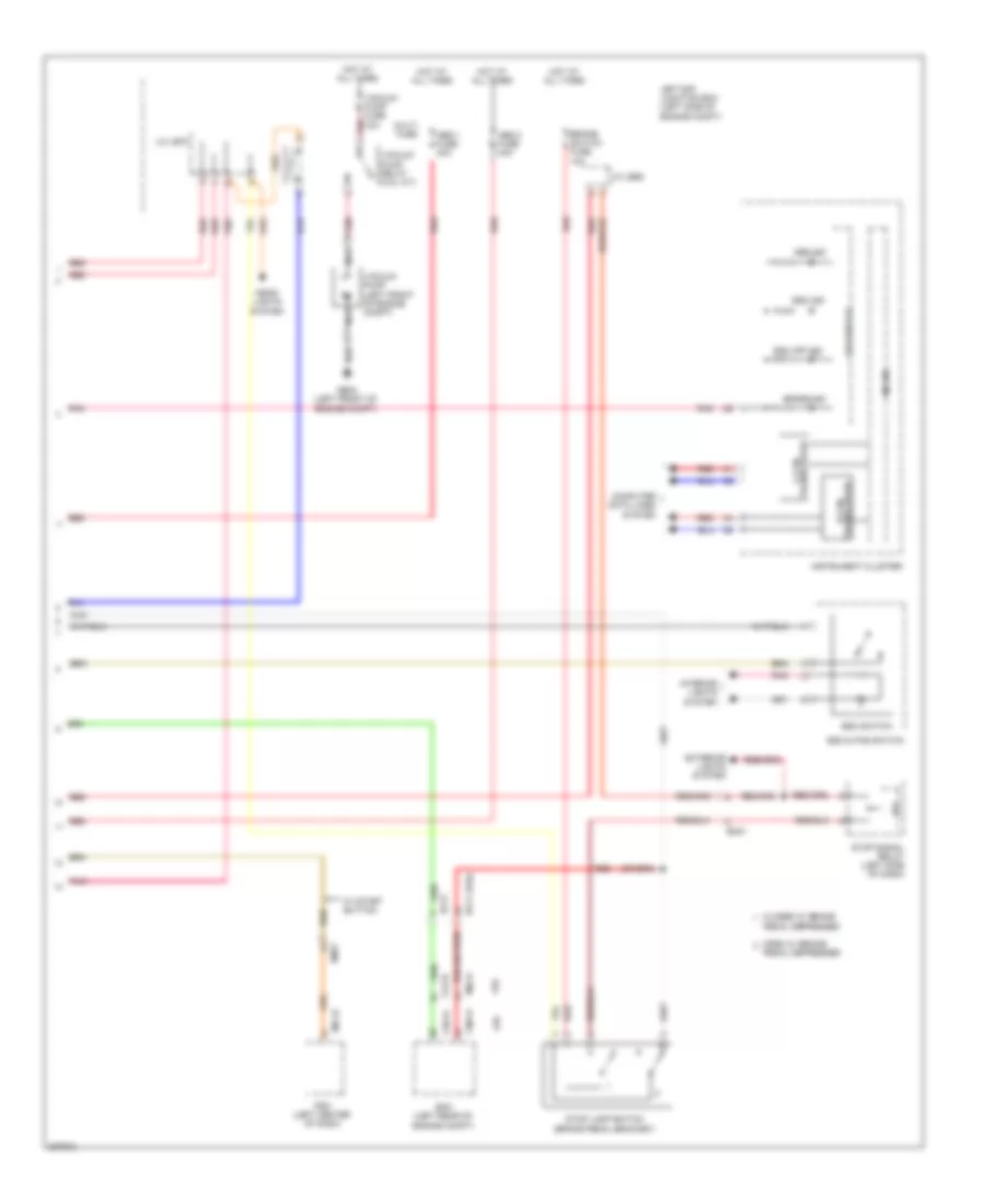
ANTI-LOCK BRAKES
Anti-lock Brakes Wiring Diagram (1 of 2) for Hyundai Genesis Coupe 2.0T Premium 2013
 https://portal-diagnostov.com/license.html
Automotive Electricians Portal FZCO
Automotive Electricians Portal FZCO
https://portal-diagnostov.com/license.html
https://portal-diagnostov.com/license.html
Automotive Electricians Portal FZCO
Automotive Electricians Portal FZCOList of elements for Anti-lock Brakes Wiring Diagram (1 of 2) for Hyundai Genesis Coupe 2.0T Premium 2013:
- 2.0l
- 3.8l
- 7.5a
- A/v & navigation head unit
- Abs fuse 7.5a
- Abs/esc control module (left front of engine compt)
- B+ (motor)
- B+ (solenoid)
- B-can hi
- B-can lo
- Brake fluid level sensor (brake fluid reservoir)
- Brake light switch
- Brake test switch
- Brk fld level
- C-can high
- C-can low
- Can high
- Can low
- Computer data lines system
- Ec21
- Ef11
- Em21
- Em51
- Esc switch
- Esc unit
- Fl sig
- Fl vcc
- Fr sig
- Fr vcc
- Fr wheel sens output
- Ge05 (right rear of engine compt)
- Ge07 (left kick panel)
- Gm02 (left side of dash)
- Gnd
- Ground
- Hot in on
- Hot in on or start
- I/p-c
- I/p-d
- I/p-e
- I/p-g
- Ips control module
- J/c jm01 (left side of dash)
- Left front wheel sensor (left front wheel hub)
- Left rear wheel sensor (left rear wheel hub)
- M70-b
- Mf11
- Module 2 fuse 7.5a
- Module 4 fuse
- Nca
- On/start
- On/start input
- Parking
- Parking brake sw
- Parking brake switch (base of parking brake lever assembly)
- Parking brk sw
- Pnk
- Power
- Red
- Right front wheel sensor (right front wheel hub)
- Right rear wheel sensor (right rear wheel hub)
- Rl sig
- Rl vcc
- Rr sig
- Rr vcc
- Rr wheel sens output
- Smart junction box
- Steering angle sensor (top of steering column)
- Vacuum pum relay con
- Vacuum switch
- Vacuum switch (2.0l a/t) (left rear of engine compt)
- W/ navigation
- Yaw rate sensor (center console)
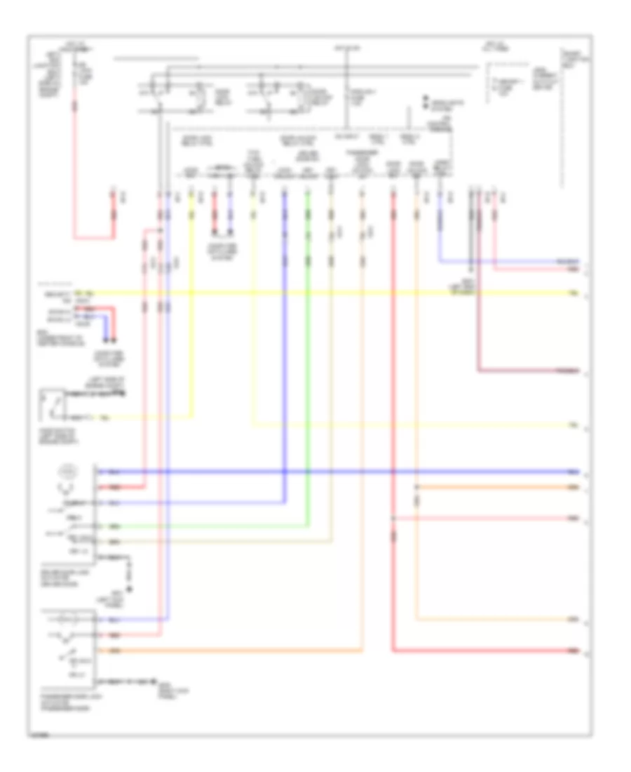
Anti-lock Brakes Wiring Diagram (2 of 2) for Hyundai Genesis Coupe 2.0T Premium 2013
 https://portal-diagnostov.com/license.html
Automotive Electricians Portal FZCO
Automotive Electricians Portal FZCO
https://portal-diagnostov.com/license.html
https://portal-diagnostov.com/license.html
Automotive Electricians Portal FZCO
Automotive Electricians Portal FZCOList of elements for Anti-lock Brakes Wiring Diagram (2 of 2) for Hyundai Genesis Coupe 2.0T Premium 2013:
- (2.0l)
- 2.0l
- 3.8l
- Abs 1 fuse 40a
- Abs 2 fuse 40a
- Abs ind
- Brake ind
- Brake switch fuse 10a
- Chg-a
- Chg-k
- Clg-b
- Closed w/ brake
- Computer data lines system
- Ec11
- Ec21
- Ecm (left rear of engine compt)
- Elg-a
- Em21
- Esc & pas switch
- Esc ind
- Esc off ind
- Esc switch
- Exterior lights system
- Ge03 (left front of engine compt)
- Head- lights system
- Hot at all times
- Instrument cluster
- Interior lights system
- Ips
- J/c je68
- J/c je70
- Led drive ic
- Left e/r junction box (left side of engine compt)
- M51-b
- Micom
- Multi fuse
- Nca
- Open w/ brake
- Pdm (left center of dash)
- Pedal depressed
- Pnk
- Red
- Stop lamp switch (brake pedal bracket)
- Stop signal relay (left side of dash)
- Transceiver b-can
- Transceiver c-can
- Vacuum pump (left front of engine compt)
- Vacuum pump fuse 15a
- Vacuum pump relay (2.0l a/t)
- W/ start button
ANTI-THEFT
Forced Entry Wiring Diagram (1 of 2) for Hyundai Genesis Coupe 2.0T Premium 2013
 https://portal-diagnostov.com/license.html
Automotive Electricians Portal FZCO
Automotive Electricians Portal FZCO
https://portal-diagnostov.com/license.html
https://portal-diagnostov.com/license.html
Automotive Electricians Portal FZCO
Automotive Electricians Portal FZCOList of elements for Forced Entry Wiring Diagram (1 of 2) for Hyundai Genesis Coupe 2.0T Premium 2013:
- (left side of engine compt) ge04
- 87a
- Arisu 1 ctrl
- Arisu 2 ctrl
- B-can
- B-can hi
- B-can lo
- Bcm (under front of center console)
- Box
- Computer data lines system
- Door lock relay
- Door lock relay ctrl
- Door lock sw
- Door unlock relay
- Door unlock relay ctrl
- Door unlock sw
- Dr lk
- Dr lock fuse 10a
- Dr unlk
- Driver door lock actuator (driver door)
- Driver door sw
- Fd11
- Fd21
- Gf01 (left kick panel)
- Gf05 (right kick panel)
- Gm01 (left end of dash)
- Headlights system
- High
- Hood sw
- Hood switch (left side of engine compt)
- Horn relay ctrl
- Hot at all times
- Hot in on
- I/p-b
- I/p-c
- I/p-d
- I/p-e
- I/p-f
- I/p-g
- Ips control module
- Key lk
- Key lock
- Key unlk
- Key unlock
- Leak current auto cut device
- Left e/r junction box (left side of engine compt)
- Lock/ unlock
- Low
- M02-b
- Memory 1 fuse 10a
- Module 4 fuse 7.5a
- Nca
- On input
- Passenger door lock actuator (passenger door)
- Passenger door lock/ unlock sw
- Red
- Security ind m02-c
- Smart junction
- Two turn unlock relay ctrl
Forced Entry Wiring Diagram (2 of 2) for Hyundai Genesis Coupe 2.0T Premium 2013
 https://portal-diagnostov.com/license.html
Automotive Electricians Portal FZCO
Automotive Electricians Portal FZCO
https://portal-diagnostov.com/license.html
https://portal-diagnostov.com/license.html
Automotive Electricians Portal FZCO
Automotive Electricians Portal FZCOList of elements for Forced Entry Wiring Diagram (2 of 2) for Hyundai Genesis Coupe 2.0T Premium 2013:
- 87a
- Auto light & photo sensor (top center of dash)
- Dr lk
- Dr unlk
- Driver door lock switch
- Ee11
- Fd11
- Fd21
- Ge03 (left front of engine compt)
- Gf01 (left kick panel)
- Gf05 (right kick panel)
- Gm01 (left end of dash)
- Horn fuse 15a
- Horn relay
- Horns system
- Hot at all times
- I/p-d
- Icm relay box (left side of dash)
- Left e/r junction box (left side of engine compt)
- Left horn (center of radiator support)
- M13-a
- Mf11
- Nca
- Passenger door lock switch
- Passenger power window switch
- Pnk
- Power window main switch
- Red
- Right horn (center of radiator support)
- Security indicator
- Two turn unlock relay
Immobilizer Wiring Diagram, with Button Start for Hyundai Genesis Coupe 2.0T Premium 2013
 https://portal-diagnostov.com/license.html
Automotive Electricians Portal FZCO
Automotive Electricians Portal FZCO
https://portal-diagnostov.com/license.html
https://portal-diagnostov.com/license.html
Automotive Electricians Portal FZCO
Automotive Electricians Portal FZCOList of elements for Immobilizer Wiring Diagram, with Button Start for Hyundai Genesis Coupe 2.0T Premium 2013:
- (left end of dash) gm01
- (left side of dash) gm02
- (left side of package tray panel) rf receiver
- (right kick panel) gf05
- 2.0l
- 3.8l
- 5v regulator
- Acc/on input
- Ast dr anr gnd
- Ast dr ant (+)
- Ast dr lk sig
- B-can hi
- B-can lo
- B-can tranceiver
- Brake
- Bum ant (+)
- Bum ant (-)
- Buzz (+)
- Chg-k
- Computer data lines system
- Data
- Diag-k
- Driver smart key outside handle
- Drv dr ant (+)
- Drv dr ant gnd
- Drv dr lk sig
- Ec11
- Ecm (left rear of engine compt)
- Elg-a
- Em51
- Ems com
- Exterior lights system
- Fd11
- Fd21
- Ff11
- Ge03 (left front of engine compt)
- Gf01 (left kick panel)
- Gf07 (right "c" pillar)
- Gnd
- Gnd p-position sw (a/t) ignition lock
- Ground
- High
- Hot at all times
- Hot in acc or on
- Hot in on or start
- I/p-a
- I/p-c
- I/p-d
- Immo ind
- Immobilizer ind
- Instrument cluster
- Intr ant 1 (+)
- Intr ant 1 (-)
- Intr ant 2 (+)
- Intr ant 2 (-)
- Key out ind
- Leak current auto cut device
- Led drive ic
- Lock
- Low
- M14-a
- M14-b
- Memory 1 fuse 10a
- Memory 2 fuse 7.5a
- Mf11
- Mf31
- Micom
- Module 2 fuse 7.5a
- Module 3 fuse 10a
- Module 6 fuse 10a
- Nca
- On/start input
- Passenger smart key outside handle
- Pdm 2 fuse 10a
- Pnk
- Power
- Red
- Rf sig
- Smart junction box
- Smart key bumper antenna (behind center of rear bumper)
- Smart key control module (right side of dash)
- Smart key external buzzer (rear of left front wheelwell)
- Smart key interior antenna 1 (under front of center console)
- Smart key interior antenna 2
- Smart key trunk antenna (rear of trunk)
- Ssb sw 2
- Start stop button switch
- Starting/charging system
- Sw 2
- Trunk ant (+)
- Trunk ant (-)
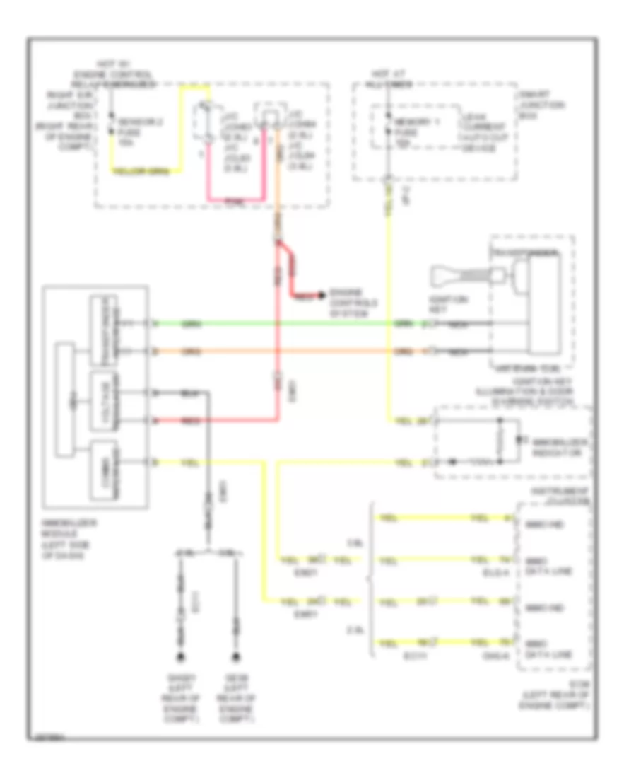
Immobilizer Wiring Diagram, without Button Start for Hyundai Genesis Coupe 2.0T Premium 2013
 https://portal-diagnostov.com/license.html
Automotive Electricians Portal FZCO
Automotive Electricians Portal FZCO
https://portal-diagnostov.com/license.html
https://portal-diagnostov.com/license.html
Automotive Electricians Portal FZCO
Automotive Electricians Portal FZCOList of elements for Immobilizer Wiring Diagram, without Button Start for Hyundai Genesis Coupe 2.0T Premium 2013:
- (+)
- (-)
- (left side of dash)
- 2.0l
- 3.8l
- Antenna coil
- Chg-k
- Cpu
- Ec11
- Ec21
- Ecm (left rear of engine compt)
- Elg-a
- Em21
- Em51
- Engine controls system
- Ge08 (left rear of engine compt)
- Ghg01 (left rear of engine compt)
- Hot at all times
- Hot w/ engine control relay energized
- I/p-c
- Ignition key
- Ignition key illumination & door warning switch
- Immo data line
- Immo ind
- Immobilizer indicator
- Immobilizer module
- Instrument cluster
- Interface comms
- Interface transponder
- J/c jch83 (2.0l) j/c jcl83 (3.8l)
- J/c jch84 (2.0l) j/c jcl84 (3.8l)
- Leak current auto cut device
- Memory 1 fuse 10a
- Nca
- Pnk
- Red
- Regulator voltage
- Right e/r junction box (right rear of engine compt)
- Sensor 2 fuse 15a
- Smart junction box
- Transponder
BODY CONTROL MODULES
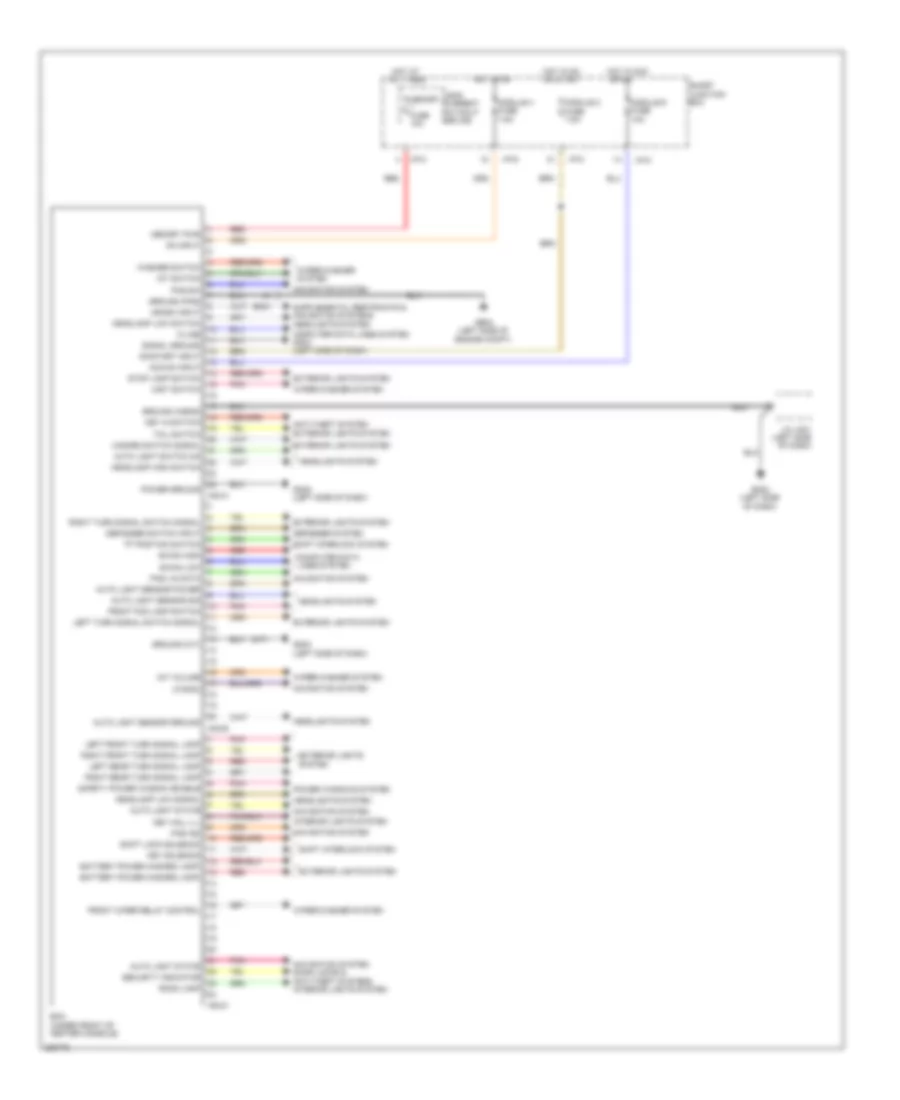
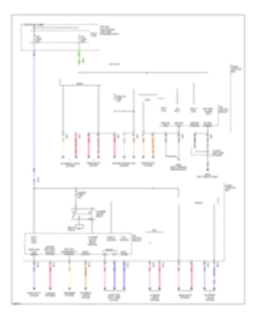
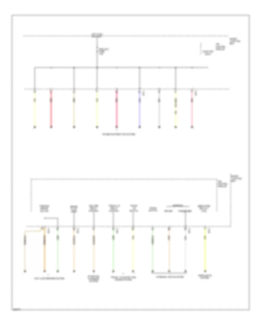
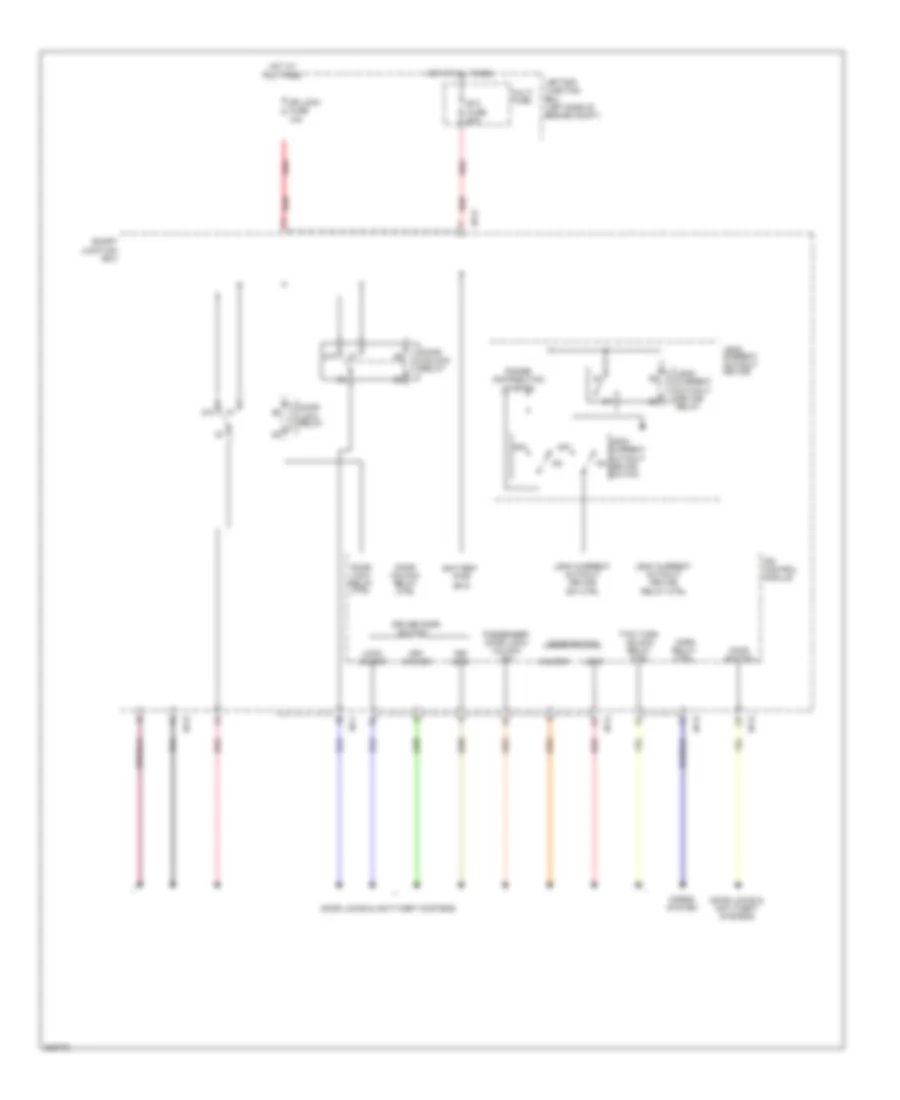
Body Control Module Wiring Diagram for Hyundai Genesis Coupe 2.0T Premium 2013
 https://portal-diagnostov.com/license.html
Automotive Electricians Portal FZCO
Automotive Electricians Portal FZCO
https://portal-diagnostov.com/license.html
https://portal-diagnostov.com/license.html
Automotive Electricians Portal FZCO
Automotive Electricians Portal FZCOList of elements for Body Control Module Wiring Diagram for Hyundai Genesis Coupe 2.0T Premium 2013:
- "p" position switch
- (m/t)
- Acc/on input
- Anti-theft system
- Auto light sensor ground
- Auto light sensor power
- Auto light sensor sig
- Auto light state
- Auto light switch on
- B-can high
- B-can low
- Battery power (hazard lamp)
- Bcm (under front of center console)
- Computer data lines system
- Computer data lines system gm03 (left side of dash)
- Crash input
- Defogger switch input
- Defogger system
- Em21
- Exterior lights system
- Front fog lamp switch
- Front wiper relay control
- Ge04 (left side of engine compt)
- Gm02 (left side of dash)
- Gm03 (left side of dash)
- Ground (a/bag)
- Ground (m/t)
- Ground (pas)
- Hazard switch signal
- Headlamp high switch
- Headlamp low signal
- Headlamp low switch
- Headlights system
- Hot at all times
- Hot in acc
- Hot in on
- I/p-c
- I/p-d
- Int switch
- Int volume
- Interior lights system
- J/c jm01 (left side of dash)
- K-line
- Key hall ill
- Key in switch
- Key solenoid
- Leak current autocut device
- Left front turn signal lamp
- Left rear turn signal lamp
- Left turn signal switch signal
- M02-a
- M02-b
- M02-c
- Memory fuse 10a
- Memory pwr
- Mist switch
- Module 2 fuse 7.5a
- Module 4 fuse 7.5a
- Module 6 fuse 10a
- Mts-rx
- Navigation system
- Navigation system door locks & anti-theft systems interior lights system
- On input
- On/start input
- Or on
- Or start
- Pas ind
- Pas lin data
- Pas sw
- Pnk
- Power ground
- Power windows system
- Red
- Right front turn signal lamp
- Right rear turn signal lamp
- Right turn signal switch signal
- Room lamp
- Safety power window enable
- Security indicator
- Shift interlock system
- Shift lock solenoid
- Signal ground
- Smart junction box
- Stop lamp switch
- Tail switch
- Washer switch
- Wiper/washer system
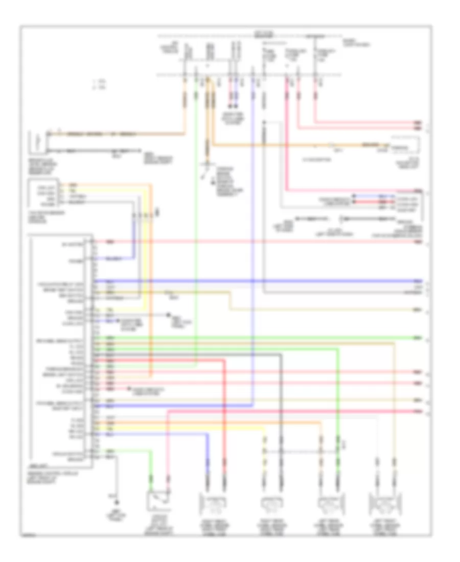
IPS Control Module Wiring Diagram (1 of 3) for Hyundai Genesis Coupe 2.0T Premium 2013
 https://portal-diagnostov.com/license.html
Automotive Electricians Portal FZCO
Automotive Electricians Portal FZCO
https://portal-diagnostov.com/license.html
https://portal-diagnostov.com/license.html
Automotive Electricians Portal FZCO
Automotive Electricians Portal FZCOList of elements for IPS Control Module Wiring Diagram (1 of 3) for Hyundai Genesis Coupe 2.0T Premium 2013:
- Arisu 1 ctrl
- Arisu 2
- Arisu 2 control
- Arisu i
- B+1 fuse 60a
- B+2 fuse 60a
- B-can
- Batt pwr (b+2)
- Battery power (b+1)
- Body k-line
- Computer data lines system
- Ctrl
- Defogger system
- Driver seat belt buckle switch
- Exterior lights system
- Flasher sound relay
- Flasher sound relay control
- Ge05 (right rear of engine compt)
- Gm02 (left side of dash)
- Ground (drl)
- Ground (hid)
- Hazard fuse 15a
- Headlamp low signal
- Headlights system
- High
- Hot at all times
- Hot in on
- I/p-b
- I/p-d
- I/p-e
- I/p-g
- Interior lights system
- Ips 1
- Ips 1 control
- Ips 2
- Ips control module
- J/c jm01 (left side of dash)
- Left e/r junction box (left side of engine compt)
- Low
- Module 4 fuse 7.5a
- Multi fuse
- On input
- Pnk
- Power distribution system
- Power ground
- Red
- Relay sound
- Rr htd & deicer relay control
- Sensor ground
- Shift lever 'r'
- Smart junction box
- Warning systems
IPS Control Module Wiring Diagram (2 of 3) for Hyundai Genesis Coupe 2.0T Premium 2013
 https://portal-diagnostov.com/license.html
Automotive Electricians Portal FZCO
Automotive Electricians Portal FZCO
https://portal-diagnostov.com/license.html
https://portal-diagnostov.com/license.html
Automotive Electricians Portal FZCO
Automotive Electricians Portal FZCOList of elements for IPS Control Module Wiring Diagram (2 of 3) for Hyundai Genesis Coupe 2.0T Premium 2013:
- (or red)
- Anti-lock brakes system
- B/alarm relay control
- Box
- Brake fluid level
- Dedicated drl rly ctrl
- Door sw
- Driver
- Headlights system
- Hot in on or start
- I/p-c
- I/p-d
- I/p-e
- I/p-g
- Interior lights system
- Ips control module
- Junction
- Module 2 fuse 7.5a
- On/start input
- Parking brake switch
- Passenger
- Pnk
- Power distribution system
- Red
- Smart
- Smart junction box
- Starting/ charging system
- Trunk lid relay control
- Trunk lid switch
- Trunk switch
- Trunk, tailgate, fuel doors system
IPS Control Module Wiring Diagram (3 of 3) for Hyundai Genesis Coupe 2.0T Premium 2013
 https://portal-diagnostov.com/license.html
Automotive Electricians Portal FZCO
Automotive Electricians Portal FZCO
https://portal-diagnostov.com/license.html
https://portal-diagnostov.com/license.html
Automotive Electricians Portal FZCO
Automotive Electricians Portal FZCOList of elements for IPS Control Module Wiring Diagram (3 of 3) for Hyundai Genesis Coupe 2.0T Premium 2013:
- 87a
- B+3 fuse 60a
- Battery pwr (b+3)
- Distribution
- Door lock relay
- Door lock relay ctrl
- Door locks & anti-theft systems
- Door switch
- Door unlock relay
- Door unlock relay ctrl
- Dr lock fuse 10a
- Driver door
- Hood switch
- Horn relay ctrl
- Horns system
- Hot at all times
- I/p-b
- I/p-d
- I/p-e
- I/p-f
- I/p-g
- Ips control module
- Key lock
- Key unlock
- Leak current autocut device
- Leak current autocut device relay
- Leak current autocut device relay ctrl
- Leak current autocut device sw ctrl
- Leak current autocut device switch
- Left e/r junction box (left side of engine compt)
- Lock
- Lock/ unlock
- Multi fuse
- Off
- Passenger door lock/ unlock sw
- Power
- Red
- Smart junction box
- Switch
- System
- Two turn unlock relay ctrl
- Unlock
COMPUTER DATA LINES
2.0L
2.0L, Computer Data Lines Wiring Diagram (1 of 2) for Hyundai Genesis Coupe 2.0T Premium 2013
 https://portal-diagnostov.com/license.html
Automotive Electricians Portal FZCO
Automotive Electricians Portal FZCO
https://portal-diagnostov.com/license.html
https://portal-diagnostov.com/license.html
Automotive Electricians Portal FZCO
Automotive Electricians Portal FZCOList of elements for 2.0L, Computer Data Lines Wiring Diagram (1 of 2) for Hyundai Genesis Coupe 2.0T Premium 2013:
- (left end of dash) gm01
- (left kick panel)
- (left side of dash)
- (left side of dash) j/c jm03
- (left side of engine compt)
- A/t
- A/v & navigation head unit
- Abs 1 fuse 40a
- Abs 2 fuse 40a
- Abs fuse 7.5a
- Audio
- Auto head lamp leveling device unit (left rear suspension)
- B-can high
- B-can low
- Bcm (under front of center console)
- C-can high
- C-can lo c-can hi
- C-can low
- Ccp-can hi
- Ccp-can lo
- Chg-k
- Chg-t
- Data link connector (left side of dash)
- Ec21
- Ecm (left rear of engine compt)
- Em21
- Ge07
- Gm02 (left side of dash)
- Hid
- Hot at all times
- Hot in on or start
- I/p-c
- I/p-e
- J/c jch01 (left side of engine compt)
- J/c je67
- J/c jm01
- J/c jm03 (left side of dash)
- J/c jm05 (center of dash)
- K-line
- Leak current autocut device
- Left e/r junction box
- M-can hi
- M-can lo
- M/t
- M02-a
- M02-b
- M03-b
- M70-b
- Memory fuse 10a
- Mf11
- Multi fuse
- Multipurpose check connector
- Red
- Smart junction box
- Speed in
- Tcm (left rear of engine compt)
- Tire pressure monitoring module (right end of dash)
- Veh spd
- W/ hid
- W/ navigation
- W/o navigation
2.0L, Computer Data Lines Wiring Diagram (2 of 2) for Hyundai Genesis Coupe 2.0T Premium 2013
 https://portal-diagnostov.com/license.html
Automotive Electricians Portal FZCO
Automotive Electricians Portal FZCO
https://portal-diagnostov.com/license.html
https://portal-diagnostov.com/license.html
Automotive Electricians Portal FZCO
Automotive Electricians Portal FZCOList of elements for 2.0L, Computer Data Lines Wiring Diagram (2 of 2) for Hyundai Genesis Coupe 2.0T Premium 2013:
- (left front of engine compt) esc module
- A/c control module
- Amp (haco) (right quarterpanel)
- Amp (jbl) (right quarterpanel)
- Automatic a/c
- B-can hi
- B-can high
- B-can lo
- B-can low
- Body k-line
- C-can hi
- C-can high
- C-can lo
- C-can lo c-can hi
- C-can low
- Can hi
- Can lo
- Can lo can hi
- Diag k
- Driver seat belt buckle switch (driver seat belt buckle)
- Ef11
- Em51
- F03-a
- F04-a
- F81-b
- Haco
- I/p-d
- Instrument cluster
- Ips control module
- J/c jabag (under front passenger seat)
- J/c jm04 (left side of dash)
- J/c jm06 (center of dash)
- Jbl
- K-line
- M-can hi
- M-can high
- M-can lo
- M-can low
- M06-a
- M07-a
- M11
- M14-a
- M51-b
- M71-a
- Manual a/c
- Mf31
- Mts module
- Multi gauge
- Multi monitor (w/o navigation)
- Passenger seat belt buckle switch (passenger seat belt buckle)
- Pdm (left center of dash)
- Pods module (under passenger seat)
- Red
- Smart junction box
- Smart key control module (right side of dash)
- Speed sig
- Srs control module (center console)
- Steering angle sensor (top of steering column)
- W/ button start
- Yaw rate sensor (center console)
3.8L
3.8L, Computer Data Lines Wiring Diagram (1 of 2) for Hyundai Genesis Coupe 2.0T Premium 2013
 https://portal-diagnostov.com/license.html
Automotive Electricians Portal FZCO
Automotive Electricians Portal FZCO
https://portal-diagnostov.com/license.html
https://portal-diagnostov.com/license.html
Automotive Electricians Portal FZCO
Automotive Electricians Portal FZCOList of elements for 3.8L, Computer Data Lines Wiring Diagram (1 of 2) for Hyundai Genesis Coupe 2.0T Premium 2013:
- (left end of dash) gm01
- (left kick panel)
- (left side of dash)
- (left side of dash) j/c jm03
- (left side of engine compt)
- A/t
- A/v & navigation head unit
- Abs 1 fuse 40a
- Abs 2 fuse 40a
- Abs fuse 7.5a
- Audio
- Auto head lamp leveling device unit (left rear suspension)
- B-can hi
- B-can lo
- Bcm (under front of center console)
- C-can high
- C-can lo c-can hi
- C-can low
- Ccp-can hi
- Ccp-can hi ccp-can lo
- Ccp-can lo
- Clg-idb
- Clg-t
- Data link connector (left side of dash)
- Ec21
- Ecm (left rear of engine compt)
- Ef11
- Elg-a
- Em21
- Ge07
- Gm02 (left side of dash)
- Hid
- Hot at all times
- Hot in on or start
- I/p-c
- I/p-e
- Injector drive box (left side of engine compt)
- J/c je67
- J/c jm01
- J/c jm03 (left side of dash)
- J/c jm05 (center of dash)
- K-line
- Leak current autocut device
- Left e/r junction box
- M-can hi
- M-can lo
- M/t
- M02-a
- M02-b
- M03-b
- M70-b
- Memory fuse 10a
- Mf11
- Multi fuse
- Multipurpose check connector
- Red
- Smart junction box
- Speed in
- Tcm (left rear of engine compt)
- Tire pressure monitoring module (right end of dash)
- Veh spd
- W/ navigation
- W/o navigation
3.8L, Computer Data Lines Wiring Diagram (2 of 2) for Hyundai Genesis Coupe 2.0T Premium 2013
 https://portal-diagnostov.com/license.html
Automotive Electricians Portal FZCO
Automotive Electricians Portal FZCO
https://portal-diagnostov.com/license.html
https://portal-diagnostov.com/license.html
Automotive Electricians Portal FZCO
Automotive Electricians Portal FZCOList of elements for 3.8L, Computer Data Lines Wiring Diagram (2 of 2) for Hyundai Genesis Coupe 2.0T Premium 2013:
- (left front of engine compt) esc module
- A/c control module
- Amp (haco) (right quarterpanel)
- Amp (jbl) (right quarterpanel)
- Auto a/c
- B-can hi
- B-can high
- B-can lo
- B-can low
- Body k-line
- C-can hi
- C-can high
- C-can lo
- C-can lo c-can hi
- C-can low
- Can hi
- Can lo
- Can lo can hi
- Diag k
- Driver seat belt buckle switch (driver seat belt buckle)
- Ef11
- Em51
- F03-a
- F04-a
- F81-b
- Haco
- I/p-d
- Instrument cluster
- Ips control module
- J/c jabag (under front passenger seat)
- J/c jm04 (left side of dash)
- J/c jm06 (center of dash)
- Jbl
- K-line
- M-can hi
- M-can high
- M-can lo
- M-can low
- M06-a
- M07-a
- M11
- M14-a
- M51-b
- M71-a
- Manual a/c
- Mf31
- Mts module
- Multi gauge
- Multi monitor (w/o navigation)
- Passenger seat belt buckle switch (passenger seat belt buckle)
- Pdm (left center of dash)
- Pods module (under passenger seat)
- Red
- Smart junction box
- Smart key control module (right side of dash)
- Speed sig
- Srs control module (center console)
- Steering angle sensor (top of steering column)
- W/ button start
- Yaw rate sensor (center console)
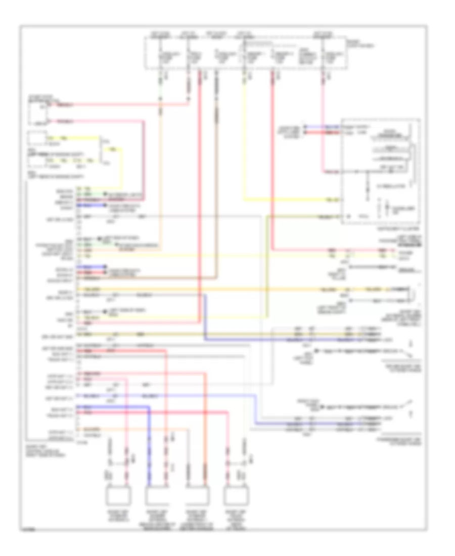
COOLING FAN
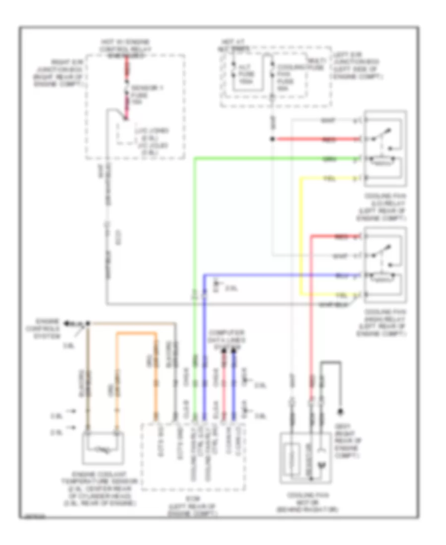
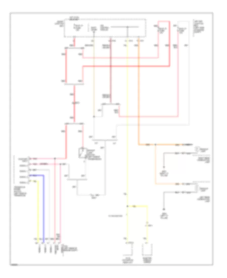
Cooling Fan Wiring Diagram for Hyundai Genesis Coupe 2.0T Premium 2013
 https://portal-diagnostov.com/license.html
Automotive Electricians Portal FZCO
Automotive Electricians Portal FZCO
https://portal-diagnostov.com/license.html
https://portal-diagnostov.com/license.html
Automotive Electricians Portal FZCO
Automotive Electricians Portal FZCOList of elements for Cooling Fan Wiring Diagram for Hyundai Genesis Coupe 2.0T Premium 2013:
- (2.0l)
- (3.8l)
- 2.0l
- 3.8l
- Alt fuse 150a
- C-can hi
- C-can lo
- Chg-k
- Clg-b
- Computer data lines system
- Cooling fan (high) relay (left rear of engine compt)
- Cooling fan (lo) relay (left rear of engine compt)
- Cooling fan fuse 60a
- Cooling fan motor (behind radiator)
- Ctrl (hi) cooling fan rly
- Ctrl (lo) cooling fan rly
- Ec11
- Ec21
- Ecm (left rear of engine compt)
- Ects gnd
- Ects sig
- Elg-a
- Engine controls system
- Engine coolant temperature sensor (2.0l: center rear of cylinder head) (3.8l: rear of engine)
- Ge01 (right rear of engine compt)
- Hot at all times
- Hot w/ engine control relay energized
- J/c jch83
- J/c jcl83
- Left e/r junction box (left side of engine compt)
- Multi fuse
- Nca
- Pnk
- Red
- Resistor
- Right e/r junction box (right rear of engine compt)
- Sensor 1 fuse 10a
CRUISE CONTROL
2.0L
2.0L, Cruise Control Wiring Diagram (1 of 2) for Hyundai Genesis Coupe 2.0T Premium 2013
 https://portal-diagnostov.com/license.html
Automotive Electricians Portal FZCO
Automotive Electricians Portal FZCO
https://portal-diagnostov.com/license.html
https://portal-diagnostov.com/license.html
Automotive Electricians Portal FZCO
Automotive Electricians Portal FZCOList of elements for 2.0L, Cruise Control Wiring Diagram (1 of 2) for Hyundai Genesis Coupe 2.0T Premium 2013:
- (+)
- (-)
- (clutch pedal assembly) (m/t) cruise clutch pedal position switch
- (left rear of engine compt) ghg01
- Accelerator pedal position sensor (accelerator pedal assembly)
- Aps 1 gnd
- Aps 1 power
- Aps 1 sig
- Aps 2 gnd
- Aps 2 power
- Aps 2 sig
- Box
- Brake sw fuse 10a
- Brk test sw
- Can hi
- Can lo
- Cancel
- Ccs gnd
- Ccs sig
- Chg-a
- Chg-k
- Clock spring
- Clutch sw
- Computer data lines system
- Cruise main
- Ec11
- Ec21
- Ecm (left rear of engine compt)
- Em21
- Etc motor & throttle position sensor (on throttle body)
- Etc output 1
- Etc output 2
- Ge05 (right rear of engine compt)
- Gnd
- Hot at all times
- Hot in on or start
- I/p-a
- I/p-c
- I/p-e
- Ill
- Interior lights system
- J/c je70
- Leak current autocut device
- Left e/r junction box (left side of engine compt)
- M48-r
- Memory 1 fuse 10a
- Module 2 fuse 7.5a
- Module 3 fuse 10a
- Motor
- Nca
- On/start in
- Pnk
- Red
- Remote control multi- function switch
- Resume/ accel
- Right cruise remote control switch
- Set/ coast
- Smart junction
- Steering wheel
- Stop lamp switch (brake pedal bracket)
- Stop lp fuse 15a
- Stop signal relay (left side of dash)
- Throttle position sensor
- Tps 1 sig
- Tps 2 sens sig
- Tps gnd
- Tps power
- Veh spd sig
2.0L, Cruise Control Wiring Diagram (2 of 2) for Hyundai Genesis Coupe 2.0T Premium 2013
 https://portal-diagnostov.com/license.html
Automotive Electricians Portal FZCO
Automotive Electricians Portal FZCO
https://portal-diagnostov.com/license.html
https://portal-diagnostov.com/license.html
Automotive Electricians Portal FZCO
Automotive Electricians Portal FZCOList of elements for 2.0L, Cruise Control Wiring Diagram (2 of 2) for Hyundai Genesis Coupe 2.0T Premium 2013:
- 4p out
- A/v & navigation head unit
- Audio
- Auto headlamp leveling device unit (left rear suspension)
- Brk test sw
- C-can high
- C-can low
- C-can transceiver
- Computer data lines
- Cruise ind
- Cruise set ind
- Data link connector (left side of dash)
- Ec21
- Ef11
- Esc module (left front of engine compt)
- Esc unit
- Fl sig
- Fl vcc
- Fr sig
- Fr vcc
- Gm02 (left side of dash)
- Hid
- High
- Instrument cluster
- J/c jm03 (left side of dash)
- Led drive ic
- Left front wheel sensor (left front wheel hub assembly)
- Left rear wheel sensor (left rear wheel hub assembly)
- Low
- M03-b
- M70-b
- Mf11
- Micom
- Nca
- Output (rr)
- Pnk
- Red
- Reducing light ic
- Regulator 5v
- Right front wheel sensor (right front wheel hub assembly)
- Right rear wheel sensor (right rear wheel hub assembly)
- Rl sig
- Rl vcc
- Rr sig
- Rr vcc
- S gnd
- Speedometer
- System
- Tachometer
- Transceiver b-can
- W/ navigation
- W/o navigation
3.8L
3.8L, Cruise Control Wiring Diagram (1 of 2) for Hyundai Genesis Coupe 2.0T Premium 2013
 https://portal-diagnostov.com/license.html
Automotive Electricians Portal FZCO
Automotive Electricians Portal FZCO
https://portal-diagnostov.com/license.html
https://portal-diagnostov.com/license.html
Automotive Electricians Portal FZCO
Automotive Electricians Portal FZCOList of elements for 3.8L, Cruise Control Wiring Diagram (1 of 2) for Hyundai Genesis Coupe 2.0T Premium 2013:
- (+)
- (-)
- (clutch pedal assembly) (m/t) cruise clutch pedal position switch
- Accelerator pedal position sensor (accelerator pedal assembly)
- Aps 1 gnd
- Aps 1 power
- Aps 1 sig
- Aps 2 gnd
- Aps 2 power
- Aps 2 sig
- Box
- Brake sw fuse 10a
- Brk test sw
- Can hi
- Can lo
- Cancel
- Ccs gnd
- Ccs sig
- Clg-b
- Clock spring
- Closed w/ brake
- Clutch sw
- Computer data lines system
- Cruise main
- Ecm (left rear of engine compt)
- Elg-a
- Em21
- Etc motor & throttle position sensor (on throttle body)
- Ge08 (left rear of engine compt)
- Glg01 (left rear of engine compt)
- Glg02 (left front of engine)
- Gnd
- Hot at all times
- Hot in on or start
- I/p-a
- I/p-c
- I/p-e
- Ill
- Interior lights system
- J/c je70
- Leak current autocut device
- Left e/r junction box (left side of engine compt)
- M48-r
- Memory 1 fuse 10a
- Module 2 fuse 7.5a
- Module 3 fuse 10a
- Motor
- Motor hi
- Motor lo
- Nca
- On/start in
- Open w/ brake
- Pedal depressed
- Pnk
- Red
- Remote control multi- function switch
- Resume/ accel
- Right cruise remote control switch
- Set/ coast
- Smart junction
- Steering wheel
- Stop lamp switch (brake pedal bracket)
- Stop lp fuse 15a
- Stop signal relay (left side of dash)
- Throttle position sensor
- Tps 1 sig
- Tps 2 sig
- Tps gnd
- Tps pwr
- Veh spd sig in
3.8L, Cruise Control Wiring Diagram (2 of 2) for Hyundai Genesis Coupe 2.0T Premium 2013
 https://portal-diagnostov.com/license.html
Automotive Electricians Portal FZCO
Automotive Electricians Portal FZCO
https://portal-diagnostov.com/license.html
https://portal-diagnostov.com/license.html
Automotive Electricians Portal FZCO
Automotive Electricians Portal FZCOList of elements for 3.8L, Cruise Control Wiring Diagram (2 of 2) for Hyundai Genesis Coupe 2.0T Premium 2013:
- 4p out
- A/v & navigation head unit
- Audio
- Auto headlamp leveling device unit (left rear suspension)
- Brk test sw
- C-can high
- C-can low
- C-can transceiver
- Computer data lines
- Cruise ind
- Cruise set ind
- Data link connector (left side of dash)
- Ec21
- Ef11
- Esc module (left front of engine compt)
- Esc unit
- Fl sig
- Fl vcc
- Fr sig
- Fr vcc
- Gm02 (left side of dash)
- Hid
- High
- Instrument cluster
- J/c jm03 (left side of dash)
- Led drive ic
- Left front wheel sensor (left front wheel hub assembly)
- Left rear wheel sensor (left rear wheel hub assembly)
- Low
- M03-b
- M70-b
- Mf11
- Micom
- Nca
- Output (rr)
- Pnk
- Red
- Reducing light ic
- Regulator 5v
- Right front wheel sensor (right front wheel hub assembly)
- Right rear wheel sensor (right rear wheel hub assembly)
- Rl sig
- Rl vcc
- Rr sig
- Rr vcc
- S gnd
- Speedometer
- System
- Tachometer
- Transceiver b-can
- W/ navigation
- W/o navigation
DEFOGGERS
Defoggers Wiring Diagram (1 of 2) for Hyundai Genesis Coupe 2.0T Premium 2013
 https://portal-diagnostov.com/license.html
Automotive Electricians Portal FZCO
Automotive Electricians Portal FZCO
https://portal-diagnostov.com/license.html
https://portal-diagnostov.com/license.html
Automotive Electricians Portal FZCO
Automotive Electricians Portal FZCOList of elements for Defoggers Wiring Diagram (1 of 2) for Hyundai Genesis Coupe 2.0T Premium 2013:
- A/c control module
- Ads act close
- Ads act f/b
- Ads act open
- Ads actuator (left side of dash)
- Air conditioning system
- Auto def data
- Auto def sck
- Auto def tmp
- Automatic a/c
- Blw motor (+)
- Defogger switch
- Deicer fuse 15a
- Deicer relay
- Fet drain
- Fet gate
- Front wiper deicer (under left side of front cowl)
- Ge03 (left front of engine compt)
- Gm02 (left side of dash)
- Gnd
- Ground
- Hot at all times
- Ind
- J/c jm01 (left side of dash)
- J/c jm03 (left side of dash)
- Left e/r junction box (left side of engine compt)
- M06-a
- M07-a
- M07-b
- Manual a/c
- Memory power
- Multi fuse
- Nca
- On input
- On/start in
- Pnk
- Red
- Rr htd fuse 40a
- Rr htd relay
- Sensor (5v)
- Sensor ground
Defoggers Wiring Diagram (2 of 2) for Hyundai Genesis Coupe 2.0T Premium 2013
 https://portal-diagnostov.com/license.html
Automotive Electricians Portal FZCO
Automotive Electricians Portal FZCO
https://portal-diagnostov.com/license.html
https://portal-diagnostov.com/license.html
Automotive Electricians Portal FZCO
Automotive Electricians Portal FZCOList of elements for Defoggers Wiring Diagram (2 of 2) for Hyundai Genesis Coupe 2.0T Premium 2013:
- Auto defogger sensor (to center of windshield)
- B-can hi
- B-can high
- B-can lo
- B-can low
- Bcm (under front of center console)
- Computer data lines system
- Data
- Defogger
- Defogger sw in
- Driver power outside mirror
- Fd11
- Fd21
- Gf01 (left kick panel)
- Gf05 (right kick panel)
- Gnd
- Hot at all times
- Hot in on
- Hot in on or start
- Htd mirror fuse 7.5a
- I/p-c
- I/p-d
- I/p-e
- I/p-f
- I/p-g
- Ips control module
- Leak current autocut device
- M02-b
- Memory 1 fuse 10a
- Module 2 fuse 7.5a
- Module 7 fuse 7.5a
- Mr11
- Nca
- Passenger power outside mirror
- Pnk
- Power (5v)
- Quarter panel ground
- Rear defogger
- Red
- Rr htd & deicer relay control
- Sck
- Smart junction box
- Tmp
ENGINE PERFORMANCE
2.0L
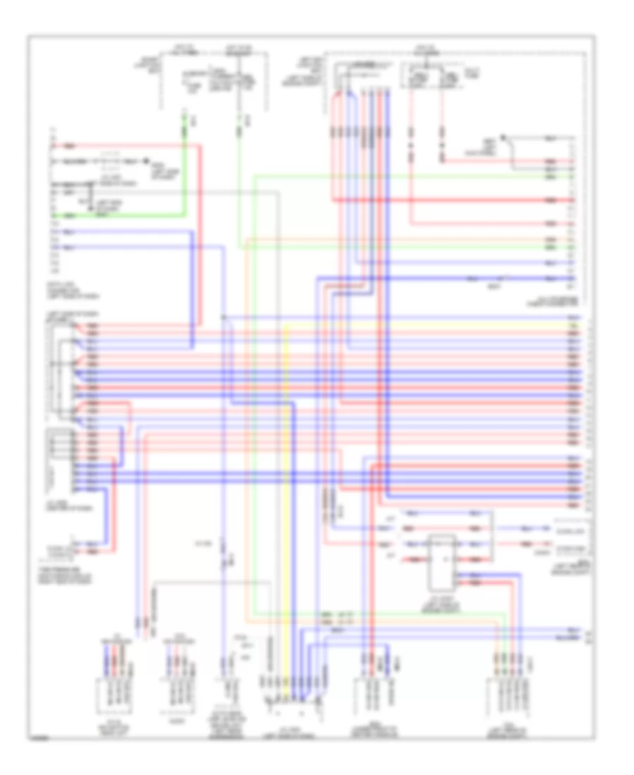
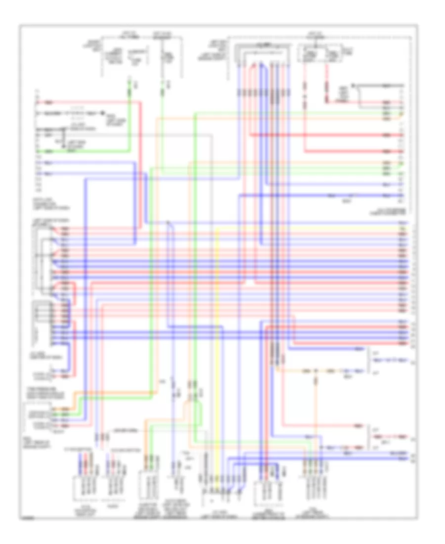
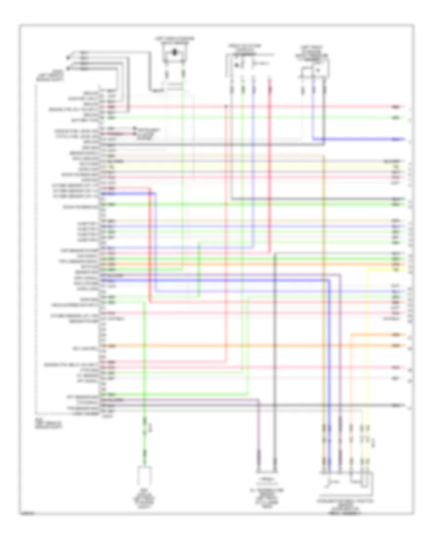
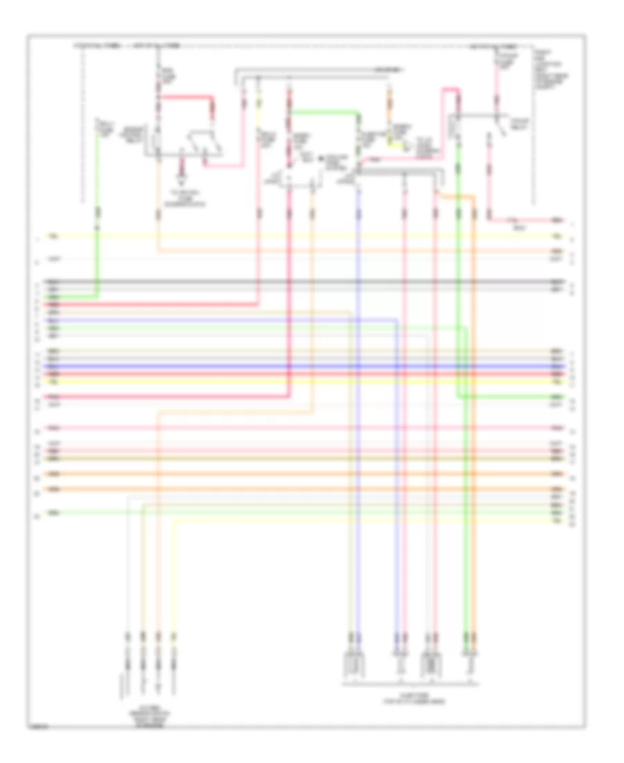
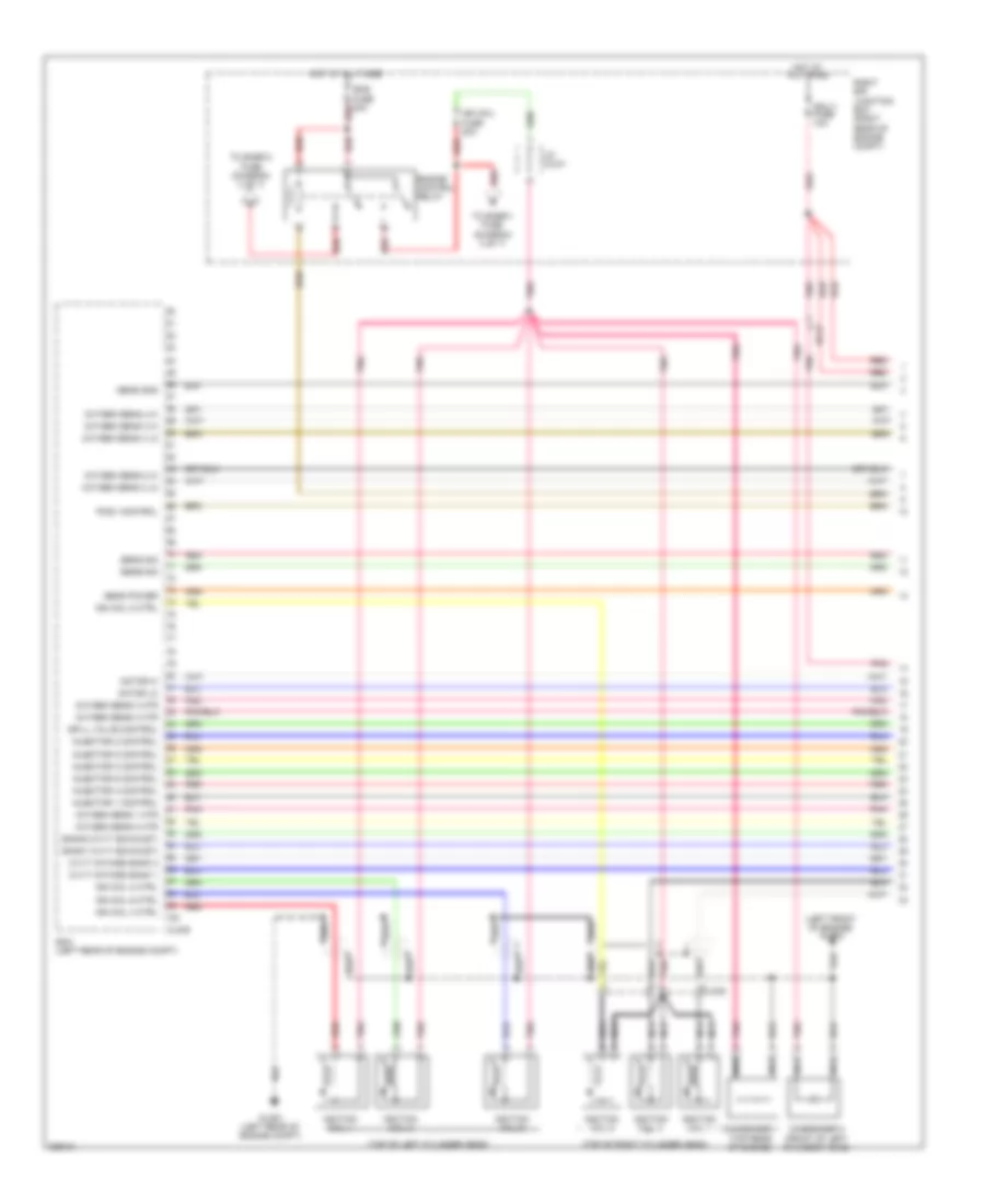
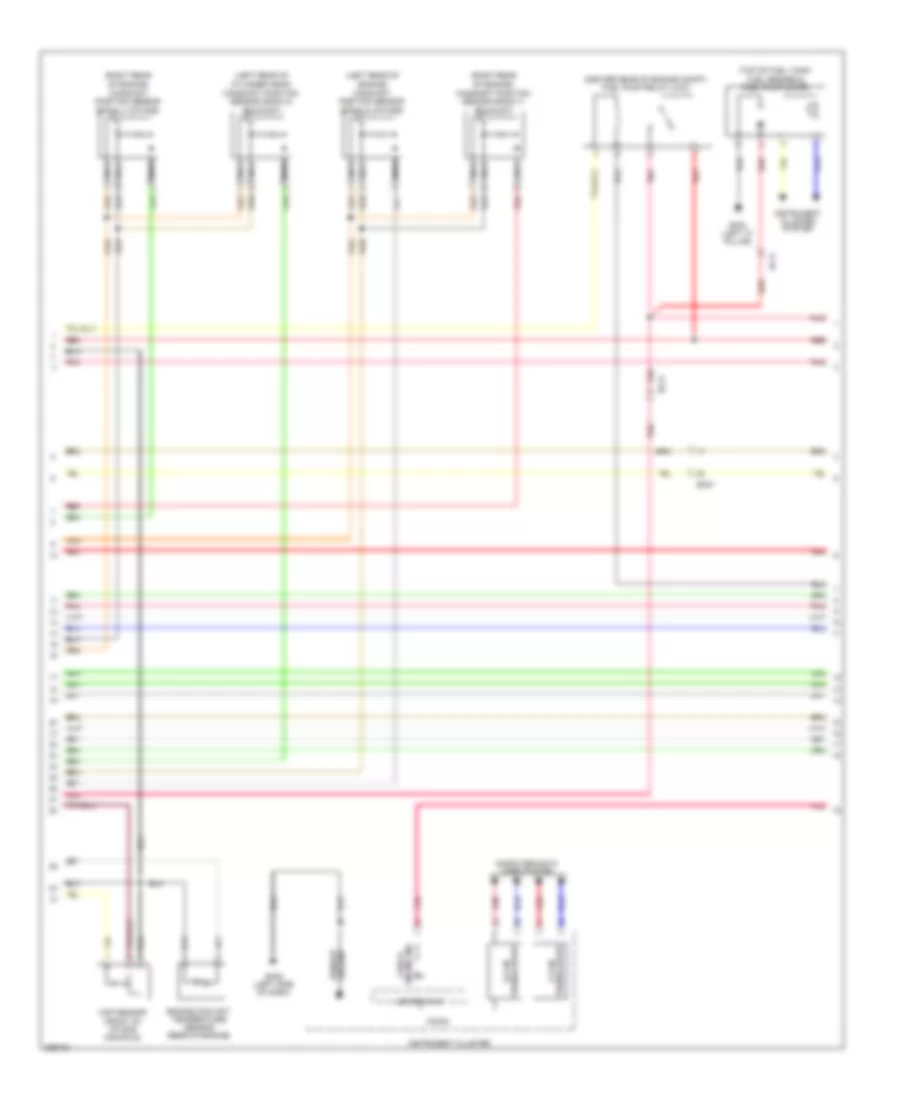
2.0L, Engine Performance Wiring Diagram (1 of 6) for Hyundai Genesis Coupe 2.0T Premium 2013
 https://portal-diagnostov.com/license.html
Automotive Electricians Portal FZCO
Automotive Electricians Portal FZCO
https://portal-diagnostov.com/license.html
https://portal-diagnostov.com/license.html
Automotive Electricians Portal FZCO
Automotive Electricians Portal FZCOList of elements for 2.0L, Engine Performance Wiring Diagram (1 of 6) for Hyundai Genesis Coupe 2.0T Premium 2013:
- (front of intake manifold) map sensor
- (left front of engine) boost pressure sensor
- (left rear of engine compt)
- (left side of engine) knock sensor
- (middle) fuel level sig
- (total) fuel level sig
- Accelerator pedal position sensor (accelerator pedal assembly)
- Aps 1 power
- Aps 2 ground
- Aps 2 power
- Aps 2 signal
- Apt sensor gnd
- Apt signal
- Battery pwr
- Bps gnd
- Bps sig
- Chg-k
- Ckps gnd
- Ckps sig
- Cmps 2 gnd
- Cmps 2 sig
- Ec11
- Ec21
- Ecm
- Ects gnd
- Ects sig
- Engine ctrl relay on input
- Engine ctrl rly on input
- Esc module (left front of engine compt)
- Ewga f/b sens gnd
- Ewga f/b sens sig
- Ftps gnd
- Ghg01 (left rear of engine compt)
- Ground
- Iat sensor
- Injector 1
- Injector 2
- Injector 3
- Injector 4
- Instrument cluster system
- Map sensor power
- Map signal
- Of cylinder head)
- Oil temperature sensor (left front
- On/start input
- Ots signal
- Oxygen sensor (up) v-g
- Oxygen sensor (up) v-ip
- Oxygen sensor (up) v-n
- Oxygen sensor (up) v-rc
- Pnk
- Rcv control
- Red
- Sensor gnd
- Sensor power
- Sensor signal
- Tps 2 sensor signal
- Tps sensor gnd
- Vehicle speed sig input
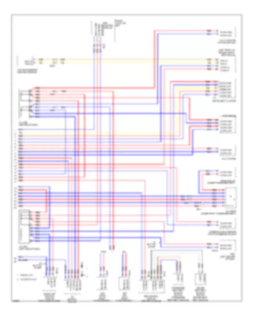
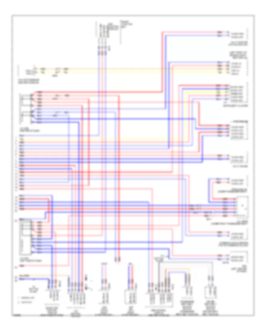
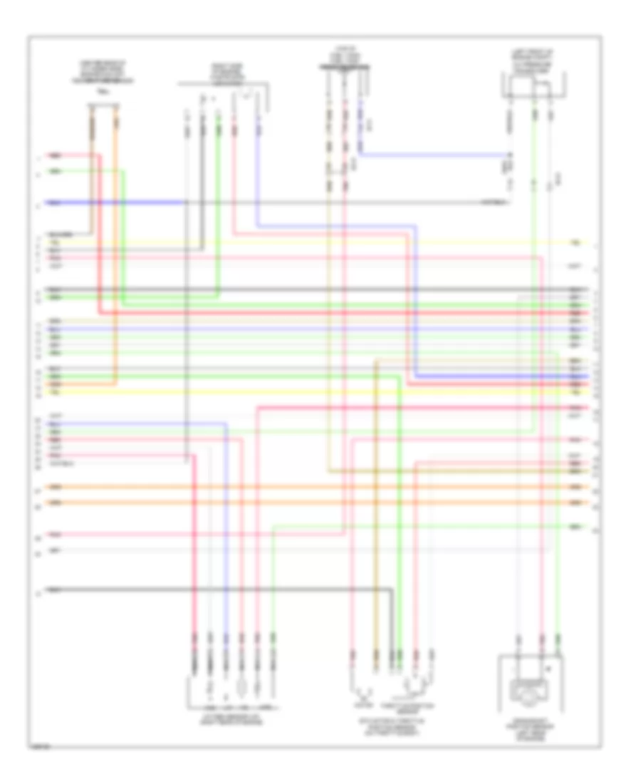
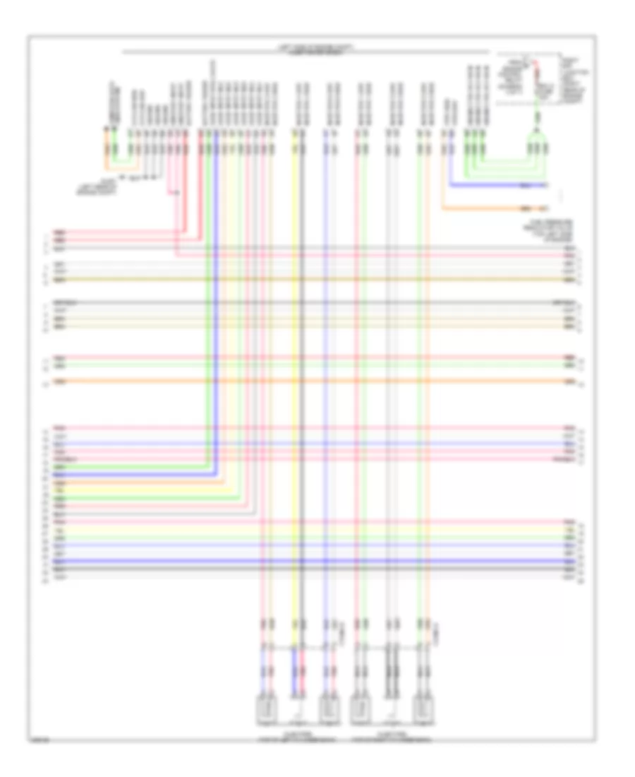
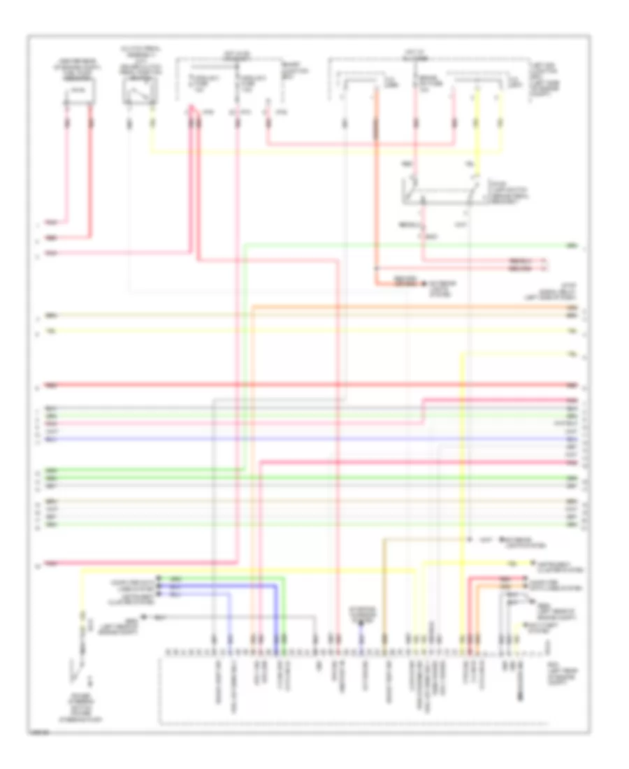
2.0L, Engine Performance Wiring Diagram (2 of 6) for Hyundai Genesis Coupe 2.0T Premium 2013
 https://portal-diagnostov.com/license.html
Automotive Electricians Portal FZCO
Automotive Electricians Portal FZCO
https://portal-diagnostov.com/license.html
https://portal-diagnostov.com/license.html
Automotive Electricians Portal FZCO
Automotive Electricians Portal FZCOList of elements for 2.0L, Engine Performance Wiring Diagram (2 of 6) for Hyundai Genesis Coupe 2.0T Premium 2013:
- (center rear of cylinder head) engine coolant temperature sensor
- (left front of engine compt)
- (right side of engine) waste gate actuator
- (top of fuel tank) fuel tank pressure sensor
- A/c pressure
- Crankshaft position sensor (left rear of engine)
- Ec21
- Ef11
- Etc motor & throttle position sensor (on throttle body)
- Htr
- Motor
- Nca
- Oxygen sensor (up) (right rear of engine)
- Pnk
- Red
- Throttle position sensor
- Transducer
- Vip
- Vrc
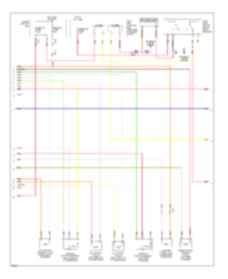
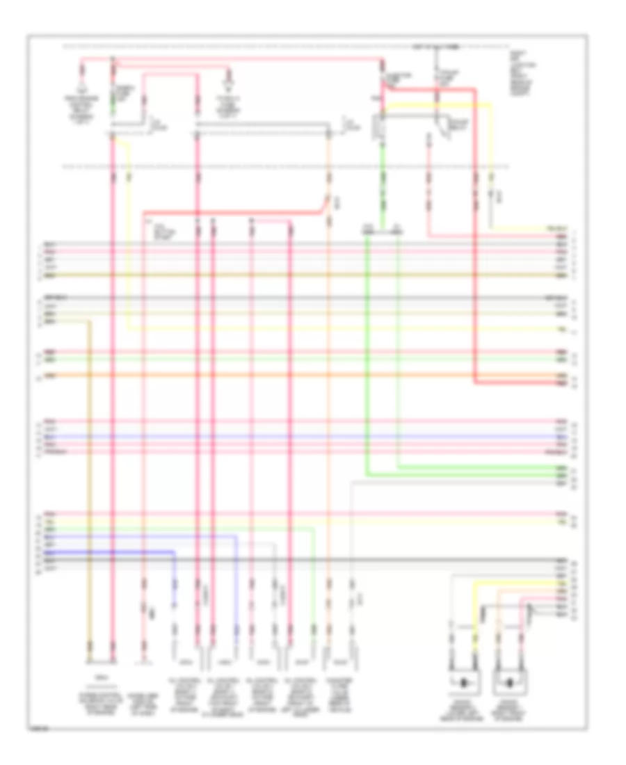
2.0L, Engine Performance Wiring Diagram (3 of 6) for Hyundai Genesis Coupe 2.0T Premium 2013
 https://portal-diagnostov.com/license.html
Automotive Electricians Portal FZCO
Automotive Electricians Portal FZCO
https://portal-diagnostov.com/license.html
https://portal-diagnostov.com/license.html
Automotive Electricians Portal FZCO
Automotive Electricians Portal FZCOList of elements for 2.0L, Engine Performance Wiring Diagram (3 of 6) for Hyundai Genesis Coupe 2.0T Premium 2013:
- (top of cylinder head)
- Cooling fans system
- Ec21
- Ecu-1 fuse 10a
- Ecu-2 fuse 20a
- Ems fuse 30a
- Engine control relay
- F/pump fuse 20a
- F/pump relay
- Hot at all times
- Injector fuse 15a
- Injectors
- J/c jch82
- J/c jch83
- J/c jch84
- Nca
- Oxygen sensor (down) (right rear of engine)
- Pnk
- Red
- Right e/r junction box (right rear of engine compt)
- Snsr-1 fuse 10a
- Snsr-2 fuse 15a
- To ign coil fuse (diagram 6 of 6)
- To j/c jch83 (diagram 4 of 6)
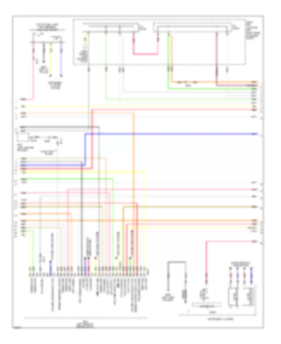
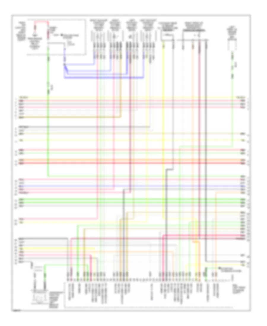
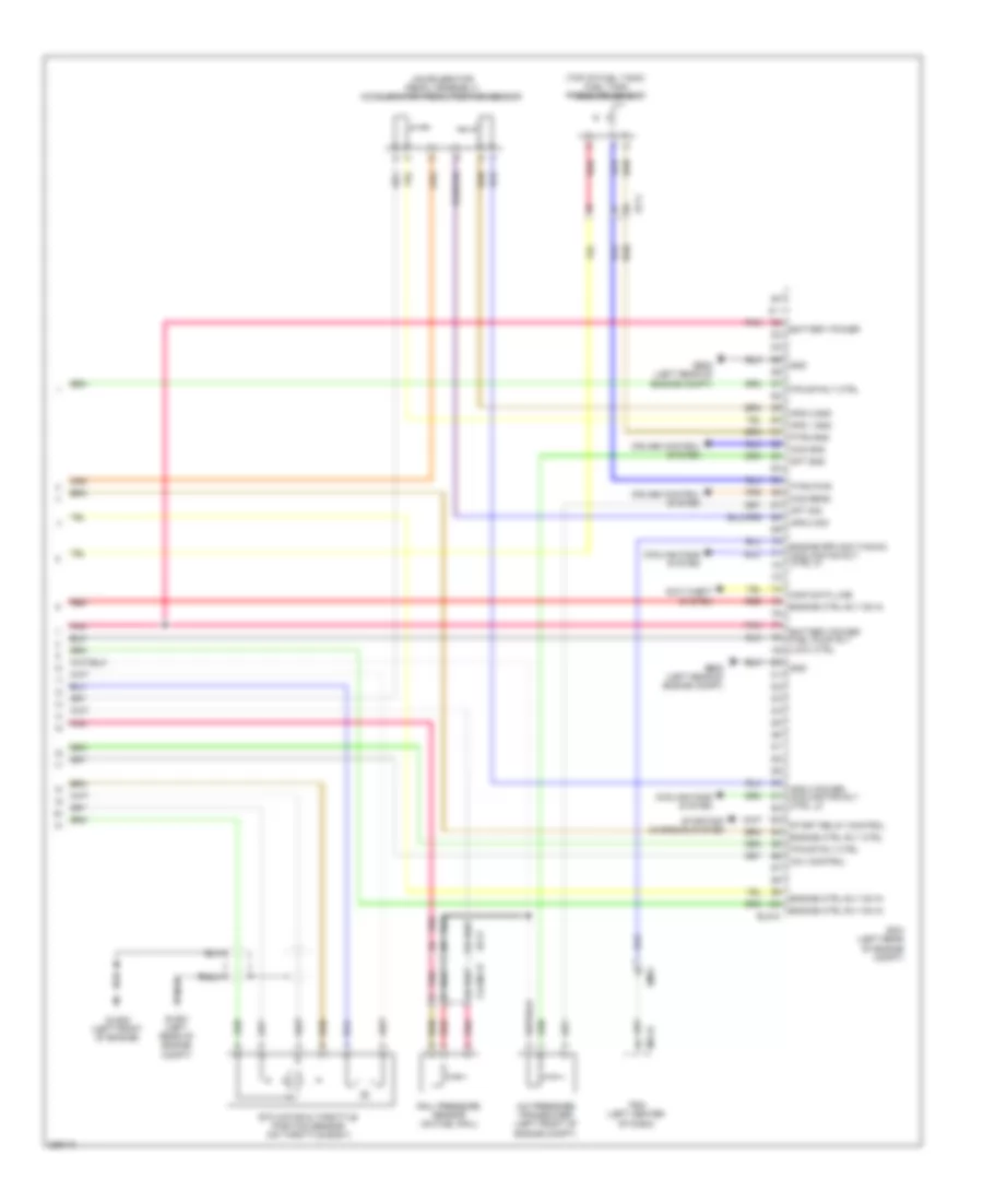
2.0L, Engine Performance Wiring Diagram (4 of 6) for Hyundai Genesis Coupe 2.0T Premium 2013
 https://portal-diagnostov.com/license.html
Automotive Electricians Portal FZCO
Automotive Electricians Portal FZCO
https://portal-diagnostov.com/license.html
https://portal-diagnostov.com/license.html
Automotive Electricians Portal FZCO
Automotive Electricians Portal FZCOList of elements for 2.0L, Engine Performance Wiring Diagram (4 of 6) for Hyundai Genesis Coupe 2.0T Premium 2013:
- (left center of dash)
- (left rear of engine compt)
- (right rear of engine compt)
- (top of fuel tank) fuel sender & fuel pump motor
- Anti-theft system
- Aps 1 gnd
- Aps 1 signal
- B-can transceiver
- C-can high
- C-can low
- C-can transceiver
- Ccv control
- Chg-k
- Cmps 1 gnd
- Cmps 1 sig
- Computer data lines system
- Cooling fan (hi) relay ctrl
- Cooling fan (lo) relay ctrl
- Cooling fans system
- Cvvt 1 ctrl
- Cvvt 2 control
- Ec11
- Ec21
- Ecm
- Ef11
- Em51
- Engine control relay ctrl
- Engine ind check
- Engine rpm signal (tacho)
- Etc output 1
- Etc output 2
- From snsr-2 fuse (diagram 3 of 6)
- Ftps signal
- Fuel pump relay ctrl
- Gf03 (left "c" pillar)
- Gm02 (left side of dash)
- Ground sensor
- Immo data line
- Immo ind
- Instrument cluster
- Instrument cluster system
- J/c jch83
- J/c jch84
- Lcd drive ic
- M51-b
- Micom
- Ots gnd
- Pcsv control
- Pdm
- Pnk
- Red
- Right e/r junction box
- Sensor gnd
- Sensor htr
- Sensor sig
- Tps 1 sensor signal
- Tps sensor power
- W/ button start
2.0L, Engine Performance Wiring Diagram (5 of 6) for Hyundai Genesis Coupe 2.0T Premium 2013
 https://portal-diagnostov.com/license.html
Automotive Electricians Portal FZCO
Automotive Electricians Portal FZCO
https://portal-diagnostov.com/license.html
https://portal-diagnostov.com/license.html
Automotive Electricians Portal FZCO
Automotive Electricians Portal FZCOList of elements for 2.0L, Engine Performance Wiring Diagram (5 of 6) for Hyundai Genesis Coupe 2.0T Premium 2013:
- (left rear of engine)
- (left side of dash) stop signal relay
- (right front of
- (right front of engine)
- (right rear of cylinder head)
- (under rear of vehicle)
- Box
- Brake sw fuse 10a
- Camshaft position sensor 1
- Camshaft position sensor 2
- Canister close valve
- Cylinder head)
- Ec11
- Ef11
- Em21
- Exterior lights system
- Hot at all times
- Hot in on or start
- I/p-c
- I/p-e
- J/c je68
- J/c je70
- Left e/r junction box (left side of engine compt)
- Module 2 fuse 7.5a
- Module 3 fuse 10a
- Oil control valve 1 (left front of cylinder head)
- Oil control valve 2
- Pedal bracket)
- Pnk
- Purge control solenoid
- Rcv control solenoid valve
- Red
- Smart junction
- Stop lamp switch (brake
- Valve (left rear of engine)
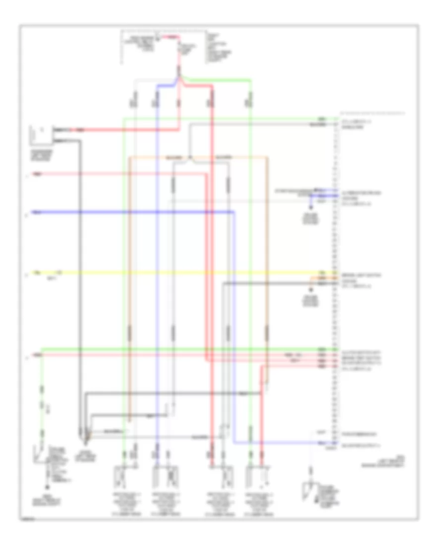
2.0L, Engine Performance Wiring Diagram (6 of 6) for Hyundai Genesis Coupe 2.0T Premium 2013
 https://portal-diagnostov.com/license.html
Automotive Electricians Portal FZCO
Automotive Electricians Portal FZCO
https://portal-diagnostov.com/license.html
https://portal-diagnostov.com/license.html
Automotive Electricians Portal FZCO
Automotive Electricians Portal FZCOList of elements for 2.0L, Engine Performance Wiring Diagram (6 of 6) for Hyundai Genesis Coupe 2.0T Premium 2013:
- (right rear of engine compt)
- (top of cylinder head)
- Alternator (fr) sig
- Brake light switch
- Brake test switch
- Ccs gnd
- Ccs sig
- Chg-a
- Clutch switch (m/t)
- Condenser (left rear of engine)
- Cruise clutch pedal position switch (m/t) (clutch pedal assembly)
- Cruise control system
- Cyl 1 (or cyl 4)
- Cyl 2 (or cyl 3)
- Cyl 3 (or cyl 2)
- Cyl 4 (or cyl 1)
- Dc motor output (+)
- Dc motor output (-)
- Ec11
- Ecm (left rear of engine compartment)
- From engine b control relay (diagram 3 of 6)
- Ge05 (right rear of engine compt)
- Ghg02 (left rear of engine)
- Ign coil fuse 20a
- Ignition coil 1 (w/ immo) ignition coil 4 (w/o immo)
- Ignition coil 2 (w/ immo) ignition coil 3 (w/o immo)
- Ignition coil 3 (w/ immo) ignition coil 2 (w/o immo)
- Ignition coil 4 (w/ immo) ignition coil 1 (w/o immo)
- Nca
- Pnk
- Power steering switch (power steering pump)
- Pwr steering sw
- Red
- Right e/r junction box
- Shield gnd
- Starting/charging system
3.8L
3.8L, Engine Performance Wiring Diagram (1 of 7) for Hyundai Genesis Coupe 2.0T Premium 2013
 https://portal-diagnostov.com/license.html
Automotive Electricians Portal FZCO
Automotive Electricians Portal FZCO
https://portal-diagnostov.com/license.html
https://portal-diagnostov.com/license.html
Automotive Electricians Portal FZCO
Automotive Electricians Portal FZCOList of elements for 3.8L, Engine Performance Wiring Diagram (1 of 7) for Hyundai Genesis Coupe 2.0T Premium 2013:
- (left front of engine) glg02
- (top of left cylinder head)
- (top of right cylinder head)
- Bank1 cvvt (exhaust)
- Bank2 cvvt (exhaust)
- Clg-b
- Clgig
- Condenser 1 (top rear of engine)
- Condenser 2 (front of left cylinder head)
- Cvvt (intake) bank 1
- Cvvt (intake) bank 2
- Ec21
- Ecm (left rear of engine compt)
- Ecu-1 fuse 10a
- Ems fuse 30a
- Engine control relay
- Glg01 (left rear of engine compt)
- Hot at all times
- Ign coil 2 ctrl
- Ign coil 4 ctrl
- Ign coil 5 ctrl
- Ign coil 6 ctrl
- Ign coil fuse 20a
- Ignition coil 1
- Ignition coil 2
- Ignition coil 3
- Ignition coil 4
- Ignition coil 5
- Ignition coil 6
- Injector 1 control
- Injector 2 control
- Injector 3 control
- Injector 4 control
- Injector 5 control
- Injector 6 control
- J/c jcl81
- Motor hi
- Motor lo
- Nca
- Oxygen sens 1 htr
- Oxygen sens 2 hi
- Oxygen sens 2 htr
- Oxygen sens 2 lo
- Oxygen sens 3 hi
- Oxygen sens 3 htr
- Oxygen sens 3 lo
- Oxygen sens 4 hi
- Oxygen sens 4 htr
- Pcsv control
- Pnk
- Red
- Right e/r junction box (right rear of engine compt)
- Sene sig
- Sens gnd
- Sens power
- Sens sig
- Spill valve control
- To snsr 2 fuse (diagram 3 of 7)
- To snsr-1 fuse (diagram 4 of 7)
3.8L, Engine Performance Wiring Diagram (2 of 7) for Hyundai Genesis Coupe 2.0T Premium 2013
 https://portal-diagnostov.com/license.html
Automotive Electricians Portal FZCO
Automotive Electricians Portal FZCO
https://portal-diagnostov.com/license.html
https://portal-diagnostov.com/license.html
Automotive Electricians Portal FZCO
Automotive Electricians Portal FZCOList of elements for 3.8L, Engine Performance Wiring Diagram (2 of 7) for Hyundai Genesis Coupe 2.0T Premium 2013:
- (left side of engine compt) injector drive box
- Battery power
- Ccp-can high
- Ccp-can low
- Clginj-a
- Computer data lines system
- Ctginj-b
- Ecu 2 fuse 20a
- Engine ctrl rly on in
- Fprv high
- Fprvlow
- From c engine control relay (diagram 3 of 7)
- Fuel pressure regulator valve (top left side of engine)
- Glg01 (left rear of engine compt)
- Ground
- Injector 1 high
- Injector 1 low
- Injector 2 high
- Injector 2 low
- Injector 3 high
- Injector 3 low
- Injector 4 high
- Injector 4 low
- Injector 5 high
- Injector 5 low
- Injector 6 high
- Injector 6 low
- Injectors (top of left cylinder bank)
- Injectors (top of right cylinder bank)
- Logic input inj1
- Logic input inj2
- Logic input inj3
- Logic input inj4
- Logic input inj5
- Logic input inj6
- Logic input spill valve
- Nca
- On/start input
- Pnk
- Red
- Right e/r junction box (right rear of engine compt)
3.8L, Engine Performance Wiring Diagram (3 of 7) for Hyundai Genesis Coupe 2.0T Premium 2013
 https://portal-diagnostov.com/license.html
Automotive Electricians Portal FZCO
Automotive Electricians Portal FZCO
https://portal-diagnostov.com/license.html
https://portal-diagnostov.com/license.html
Automotive Electricians Portal FZCO
Automotive Electricians Portal FZCOList of elements for 3.8L, Engine Performance Wiring Diagram (3 of 7) for Hyundai Genesis Coupe 2.0T Premium 2013:
- (diagram 1 of 7)
- (front of left cylinder head)
- (top front of right cylinder head)
- Canister close valve (under rear of vehicle)
- Clgocv
- Ec21
- Ef11
- Em51
- F/pump fuse 20a
- F/pump relay
- From engine control relay
- Hot at all times
- Immobilizer module (left side of dash)
- Injector fuse 15a
- J/c jcl83
- J/c jcl84
- Knock sensor 1 (right front of engine)
- Knock sensor 2 (lower left rear of engine)
- Nca
- Oil control valve 1 (bank 1) (exhaust)
- Oil control valve 2 (bank 2) (exhaust)
- Oil control valve 3 (bank 1) (intake) (front of engine)
- Oil control valve 4 (bank 2) (intake) (front of engine)
- Pnk
- Purge control solenoid valve (right rear of engine)
- Red
- Right e/r junction box (right rear of engine compt)
- Snsr-2 fuse 15a
- To ecu 2 fuse (diagram 2 of 7)
- W/ immo
- W/o button start
- W/o immo
3.8L, Engine Performance Wiring Diagram (4 of 7) for Hyundai Genesis Coupe 2.0T Premium 2013
 https://portal-diagnostov.com/license.html
Automotive Electricians Portal FZCO
Automotive Electricians Portal FZCO
https://portal-diagnostov.com/license.html
https://portal-diagnostov.com/license.html
Automotive Electricians Portal FZCO
Automotive Electricians Portal FZCOList of elements for 3.8L, Engine Performance Wiring Diagram (4 of 7) for Hyundai Genesis Coupe 2.0T Premium 2013:
- (diagram 1 of 7)
- (left exhaust manifold) oxygen sensor 2 (b2/s1)
- (left exhaust) oxygen sensor 4 (b2/s2)
- (left front of engine compt) esc module
- (right exhaust manifold) oxygen sensor 1 (b1/s1)
- (right exhaust) oxygen sensor 3 (b1/s2)
- (right front of engine compt) barometric pressure sensor
- (top right rear of engine) oil temperature sensor
- Bps sig
- Ckps hi
- Ckps lo
- Clg-b
- Cooling fans system
- Crank request
- Crankshaft position sensor (lower left rear of engine)
- Ec21
- Ecm (left rear of engine compt)
- Ects sig
- From engine control relay
- Fuel pmp res
- Iat sens
- Ign coil 1 ctrl
- Ign coil 3 ctrl
- J/c jcl83
- Knock sens 1 hi
- Knock sens 1 lo
- Knock sens 2 hi
- Knock sens 2 lo
- Map sens sig
- Nca
- Ots gnd
- Ots sig
- Oxygen sens 1 hi
- Oxygen sens 1 lo
- Oxygen sens 4 lo
- Pnk
- Red
- Right e/r junction box (right rear of engine compt)
- Sens gnd
- Sens power
- Sens sig
- Shield gnd
- Snsr-1 fuse 10a
- Starting/ charging system
- Tps 1 sig
- Tps 2 sig
- Tps gnd
- Tps power
- Vehicle spd sig in
3.8L, Engine Performance Wiring Diagram (5 of 7) for Hyundai Genesis Coupe 2.0T Premium 2013
 https://portal-diagnostov.com/license.html
Automotive Electricians Portal FZCO
Automotive Electricians Portal FZCO
https://portal-diagnostov.com/license.html
https://portal-diagnostov.com/license.html
Automotive Electricians Portal FZCO
Automotive Electricians Portal FZCOList of elements for 3.8L, Engine Performance Wiring Diagram (5 of 7) for Hyundai Genesis Coupe 2.0T Premium 2013:
- (center rear of engine compt) fuel pump relay (low)
- (front of intake manifold)
- (left rear of cylinder head) camshaft position sensor (bank 2) (exhaust)
- (left rear of engine) camshaft position sensor (bank 2) (intake)
- (right rear of engine) camshaft position sensor (bank 1) (exhaust)
- (right rear of engine) camshaft position sensor (bank 1) (intake)
- (top of fuel tank) fuel sender & fuel pump motor
- B-can transceiver
- C-can transceiver
- Computer data lines system
- Ec21
- Ef11
- Engine coolant temperature sensor (rear of engine)
- Engine ind check
- Gf03 (left "c" pillar)
- Gm02 (left side of dash)
- Ground sensor
- Instrument cluster
- Instrument cluster system
- Lcd drive ic
- Map sensor
- Micom
- Nca
- Pnk
- Red
3.8L, Engine Performance Wiring Diagram (6 of 7) for Hyundai Genesis Coupe 2.0T Premium 2013
 https://portal-diagnostov.com/license.html
Automotive Electricians Portal FZCO
Automotive Electricians Portal FZCO
https://portal-diagnostov.com/license.html
https://portal-diagnostov.com/license.html
Automotive Electricians Portal FZCO
Automotive Electricians Portal FZCOList of elements for 3.8L, Engine Performance Wiring Diagram (6 of 7) for Hyundai Genesis Coupe 2.0T Premium 2013:
- (center rear of engine compt) fuel pump resistor
- (clutch pedal assembly) (m/t) cruise clutch pedal position switch
- Alt (fr) sig
- Anti-theft system
- Aps 1 power
- Aps 1 sig
- Brake light sw
- Brake sw fuse 10a
- Brake test sw
- C-can hi
- C-can low
- Ccp-can hi
- Ccp-can lo
- Clutch sw
- Computer data lines system
- Ec21
- Ecm (left rear of engine compt)
- Elg-a
- Em21
- Exterior lights system
- Ftps sig
- Fuel lev sens sig 1
- Fuel lev sens sig 2
- Ge08 (left rear of engine compt)
- Gnd
- Hot at all times
- Hot in on or start
- I/p-c
- I/p-e
- Immobilizer ind
- Instrument cluster system
- J/c je68
- J/c je70
- Left e/r junction box (left side of engine compt)
- Module 2 fuse 7.5a
- Module 3 fuse 10a
- Nca
- On/start in
- Pnk
- Power steering switch (power steering pump)
- Pwr steering sw
- Red
- Rps sig
- Sens power
- Smart junction box
- Starting/ charging system
- Stop lamp switch (brake pedal bracket)
- Stop signal relay (left side of dash)
3.8L, Engine Performance Wiring Diagram (7 of 7) for Hyundai Genesis Coupe 2.0T Premium 2013
 https://portal-diagnostov.com/license.html
Automotive Electricians Portal FZCO
Automotive Electricians Portal FZCO
https://portal-diagnostov.com/license.html
https://portal-diagnostov.com/license.html
Automotive Electricians Portal FZCO
Automotive Electricians Portal FZCOList of elements for 3.8L, Engine Performance Wiring Diagram (7 of 7) for Hyundai Genesis Coupe 2.0T Premium 2013:
- (accelerator pedal assembly) accelerator pedal position sensor
- (top of fuel tank) fuel tank pressure sensor
- A/c pressure transducer (left front of engine compt)
- Anti-theft system
- Aps 1 gnd
- Aps 2 gnd
- Aps 2 power cooling fan rly ctrl lo
- Aps 2 sig
- Apt gnd
- Apt sig
- Battery power
- Battery power fuel pump rly (low) ctrl
- Ccs gnd
- Ccs sens
- Ccv control
- Clginj-b
- Cooling fans system
- Cruise control system
- Ec21
- Ecm (left rear of engine compt)
- Ef11
- Elg-a
- Em51
- Engine ctrl rly ctrl
- Engine ctrl rly on in
- Engine rpm sig (tacho) cooling fan rly ctrl hi
- Etc motor & throttle position sensor (on throttle body)
- F/pump rly ctrl
- Ftps gnd
- Ftps pwr
- Ge08 (left rear of engine compt)
- Glg01 (left rear of engine compt)
- Glg02 (left front of engine)
- Gnd
- Immo data line
- M51-b
- Pdm (left center of dash)
- Pnk
- Rail pressure sensor (on fuel rail)
- Red
- Start relay control
- Starting/ charging system
EXTERIOR LIGHTS
Backup Lamps Wiring Diagram for Hyundai Genesis Coupe 2.0T Premium 2013
 https://portal-diagnostov.com/license.html
Automotive Electricians Portal FZCO
Automotive Electricians Portal FZCO
https://portal-diagnostov.com/license.html
https://portal-diagnostov.com/license.html
Automotive Electricians Portal FZCO
Automotive Electricians Portal FZCOList of elements for Backup Lamps Wiring Diagram for Hyundai Genesis Coupe 2.0T Premium 2013:
- A/t
- A/v & navigation head unit
- B/up lp fuse 10a
- B/up lp fuse 15a
- Backup lamp
- Backup lamp switch (left side of transmission)
- Ec21
- Electro chromic mirror
- Gf04 (left "c" pillar)
- Gf07 (right "c" pillar)
- Hot in on or start
- I/p-a
- I/p-e
- I/p-f
- Ips control module
- Left e/r junction box (left side of engine compt)
- Left rear combination lamp
- M/t
- M70-a
- Mr11
- Nca
- On/start input
- Pnk
- Red
- Right rear combination lamp
- Shift lever 'r'
- Signal 1
- Signal 2
- Signal 3
- Signal 4
- Smart junction box
- Tcm (left rear of engine compt)
- Transaxle range switch (left side of transaxle)
- W/ navigation
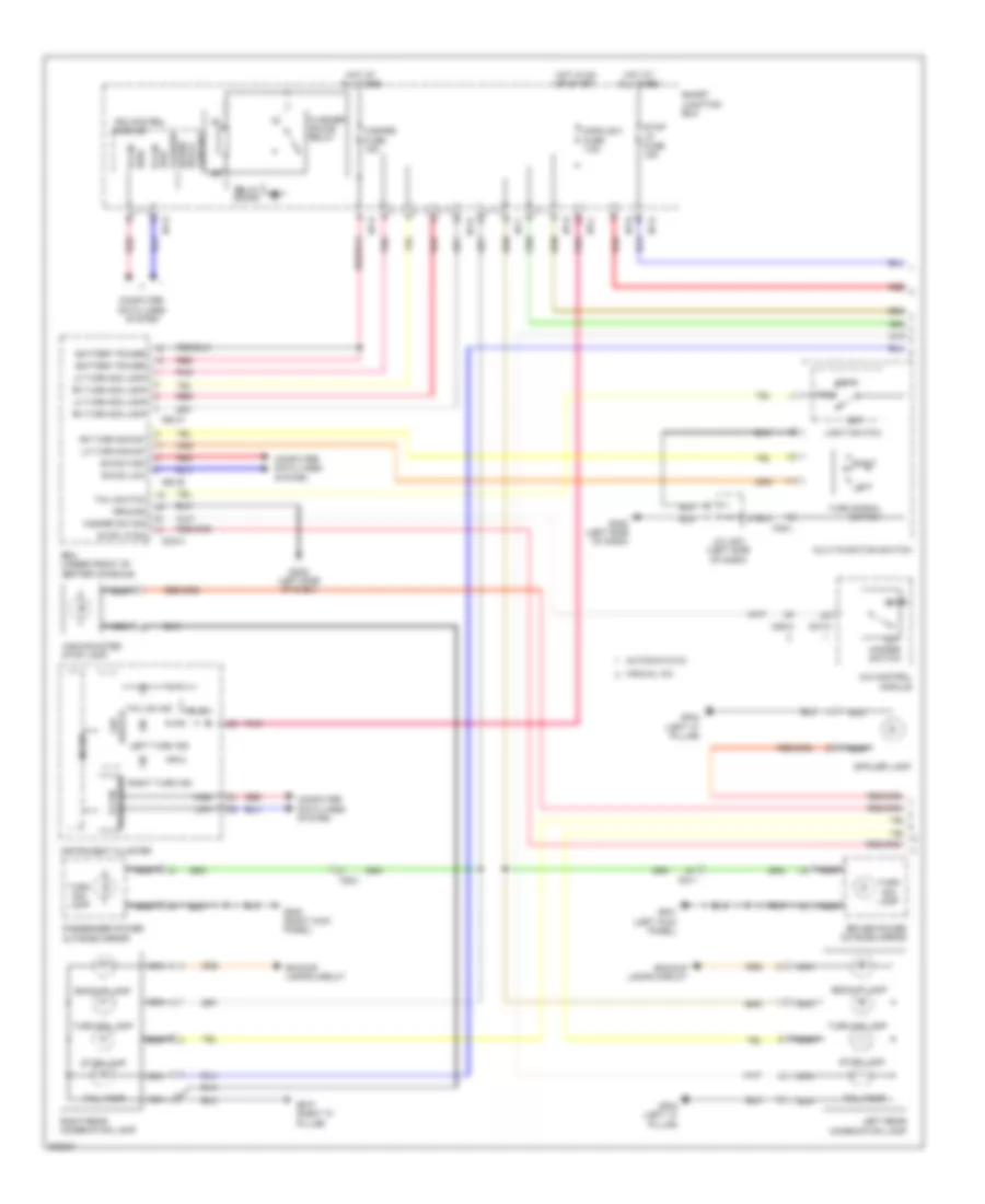
Exterior Lamps Wiring Diagram (1 of 2) for Hyundai Genesis Coupe 2.0T Premium 2013
 https://portal-diagnostov.com/license.html
Automotive Electricians Portal FZCO
Automotive Electricians Portal FZCO
https://portal-diagnostov.com/license.html
https://portal-diagnostov.com/license.html
Automotive Electricians Portal FZCO
Automotive Electricians Portal FZCOList of elements for Exterior Lamps Wiring Diagram (1 of 2) for Hyundai Genesis Coupe 2.0T Premium 2013:
- A/c control module
- Automatic a/c
- B-can high
- B-can low
- Backup lamp
- Backup lamps circuit
- Battery power
- Bcm (under front of center console)
- Computer data lines system
- Drive ic led
- Driver power outside mirror
- Fd11
- Fd21
- Flasher sound relay
- Flasher sound relay control
- Gf01 (left kick panel)
- Gf04 (left "c" pillar)
- Gf05 (right kick panel)
- Gf07 (right "c" pillar)
- Gm02 (left side of dash)
- Ground
- Hazard fuse 15a
- Hazard sw sig
- Hazard switch
- Head
- High
- High-mounted stop lamp
- Hot at all times
- Hot in on or start
- I/p-a
- I/p-b
- I/p-c
- I/p-d
- I/p-e
- I/p-f
- Instrument cluster
- Ips control module
- J/c jm01 (left side of dash)
- Left
- Left rear combination lamp
- Left turn ind
- Lh turn sig lamp
- Lh turn sig sw
- Light switch
- Low
- M02-a
- M02-b
- M02-c
- M06-a
- M07-a
- M48-l
- Manual a/c
- Micom
- Module 2 fuse 7.5a
- Multi-function switch
- Nca
- Off
- Passenger power outside mirror
- Pnk
- Red
- Relay sound
- Rh turn sig lamp
- Rh turn sig sw
- Right
- Right rear combination lamp
- Right turn ind
- Rl ic
- Smart junction box
- Spoiler lamp
- Stop lamp
- Stop lp fuse 15a
- Stop lp sw
- Tail
- Tail on ind
- Tail switch
- Tail tamp
- Tranceiver b-can
- Turn sig lamp
- Turn signal switch
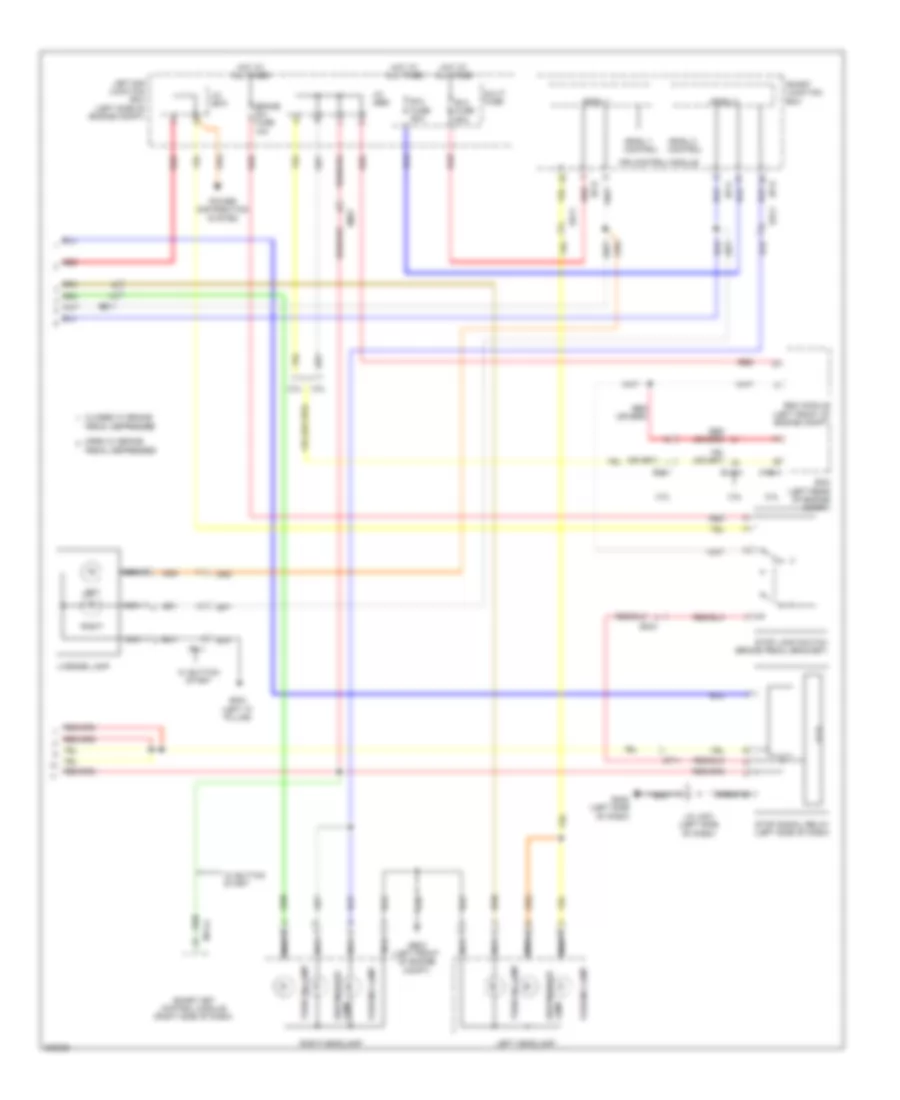
Exterior Lamps Wiring Diagram (2 of 2) for Hyundai Genesis Coupe 2.0T Premium 2013
 https://portal-diagnostov.com/license.html
Automotive Electricians Portal FZCO
Automotive Electricians Portal FZCO
https://portal-diagnostov.com/license.html
https://portal-diagnostov.com/license.html
Automotive Electricians Portal FZCO
Automotive Electricians Portal FZCOList of elements for Exterior Lamps Wiring Diagram (2 of 2) for Hyundai Genesis Coupe 2.0T Premium 2013:
- 2.0l
- 3.8l
- Arisu 1
- Arisu 1 control
- Arisu 2
- Arisu 2 control
- B+2 fuse 60a
- B+3 fuse 60a
- Brake sw fuse 10a
- Chg-a
- Closed w/ brake
- Ec11
- Ecm (left rear of engine compt)
- Ee11
- Elg-a
- Em21
- Esc module (left front of engine compt)
- Ff11
- Ge03 (left front of engine compt)
- Gf04 (left "c" pillar)
- Gm02 (left side of dash)
- Hot at all times
- I p s
- I/p-e
- I/p-g
- Ips control module
- J/c je68
- J/c je70
- J/c jm01 (left side of dash)
- Lamp side marker
- Left
- Left e/r junction box (left side of engine compt)
- Left headlamp
- License lamp
- M14-a
- Mf11
- Multi fuse
- Nca
- Open w/ brake
- Parking lamp
- Pedal depressed
- Power distribution system
- Red
- Right
- Right headlamp
- Smart junction box
- Smart key control module (right side of dash)
- Stop lamp switch (brake pedal bracket)
- Stop signal relay (left side of dash)
- Turn sig lamp
- W/ button start
GROUND DISTRIBUTION
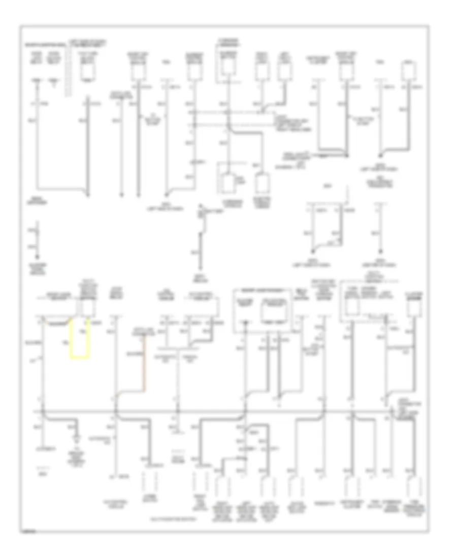
Ground Distribution Wiring Diagram (1 of 4) for Hyundai Genesis Coupe 2.0T Premium 2013
 https://portal-diagnostov.com/license.html
Automotive Electricians Portal FZCO
Automotive Electricians Portal FZCO
https://portal-diagnostov.com/license.html
https://portal-diagnostov.com/license.html
Automotive Electricians Portal FZCO
Automotive Electricians Portal FZCOList of elements for Ground Distribution Wiring Diagram (1 of 4) for Hyundai Genesis Coupe 2.0T Premium 2013:
- (center of dash)
- (left end of dash)
- (left side of dash)
- (left side of dash) icm relay box
- 87a
- A/c control module
- A/t
- Auto headlamp leveling device unit
- Automatic a/c
- Battery
- Bcm
- Blower relay
- Body ground
- Cluster ionizer
- Data link connector
- Dimmer/ passing switch
- Door lock relay
- Door unlock relay
- Ee11
- Electro chromic mirror
- Em21
- Esc & pas switch
- Fet (field effect transistor)
- From joint a connector jm01 (diagram 1 of 4)
- Front fog lamp switch
- Glove box lamp switch
- Gm01
- Gm02
- Gm03
- Gm04
- Gnd
- I/p-b
- I/p-d
- Ignition key illumination door warning switch
- Instrument cluster
- Ips control module
- Joint connector jm01 (left side of dash)
- Joint connector jr01 (left side of front headliner)
- Left headlamp leveling device actuator
- Left vanity lamp
- Light switch
- M/t
- M02-a
- M02-b
- M06-a
- M06-b
- M07-a
- M07-b
- M13-a
- M14-a
- M48-l
- M48-r
- M48-w
- M51-a
- Manual a/c
- Map lamp
- Mf11
- Mr11
- Multi gauge
- Multi- function switch
- Multi- function switch (remote control)
- Multi-function switch
- Nca
- Overhead console
- Pdm
- Quarter panel ground
- Rear defogger
- Rheostat
- Right headlamp leveling device actuator
- Right vanity lamp
- Smart junction box
- Smart key control module
- Sport mode switch
- Steering angle sensor
- Stop signal relay
- Sunroof control module
- Sunroof switch
- Tire pressure monitoring module
- To ground gm02 (diagram 1 of 4)
- Trip switch
- Turn signal switch
- Two turn unlock relay
- W/ button start
- W/o button start
- Wiper switch
Ground Distribution Wiring Diagram (2 of 4) for Hyundai Genesis Coupe 2.0T Premium 2013
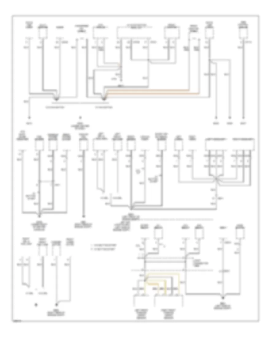 https://portal-diagnostov.com/license.html
Automotive Electricians Portal FZCO
Automotive Electricians Portal FZCO
https://portal-diagnostov.com/license.html
https://portal-diagnostov.com/license.html
Automotive Electricians Portal FZCO
Automotive Electricians Portal FZCOList of elements for Ground Distribution Wiring Diagram (2 of 4) for Hyundai Genesis Coupe 2.0T Premium 2013:
- (left side of engine compt)
- 2.0l
- 2.0l a/t
- Acc relay
- Atm shift lever indicator
- Audio
- Aux & usb jack
- Av & navigation head unit
- Bcm
- Console power outlet
- Cooling fan motor
- Ee11
- Em21
- External buzzer
- Fob holder
- Front deicer
- Front fog lamp
- Front monitor
- Front monitor shield
- Front power outlet
- Front wiper motor
- Ge01 (right rear of engine compt)
- Ge02 (right rear of engine compt)
- Ge03 (left front of engine compt)
- Ge04 (left side of engine compt)
- Gm05 (under center of dash)
- Gm06 (under front of center console)
- Gm07
- Gm08
- Gm09
- Gm10
- Gm11
- Handsfree mic shield
- Hood switch
- Ig 1 relay
- Ig 2 relay
- Joint connector je68
- Left
- Left drl & fog lamp
- Left e/r junction box
- Left front parking assist sensor
- Left headlamp
- Left horn
- M02-a
- M03-b
- M70-b
- M70-c
- M71-a
- Mm11
- Mts
- Mts module
- Multi monitor
- Nca
- Right
- Right drl & fog lamp
- Right front parking assist sensor
- Right headlamp
- Right horn
- Smart key
- Srs control module
- Start relay
- Vacuum pump
- W/ button start
- W/ drl
- W/ navigation
- W/o button start
- W/o drl
- W/o navigation
- Washer motor
Ground Distribution Wiring Diagram (3 of 4) for Hyundai Genesis Coupe 2.0T Premium 2013
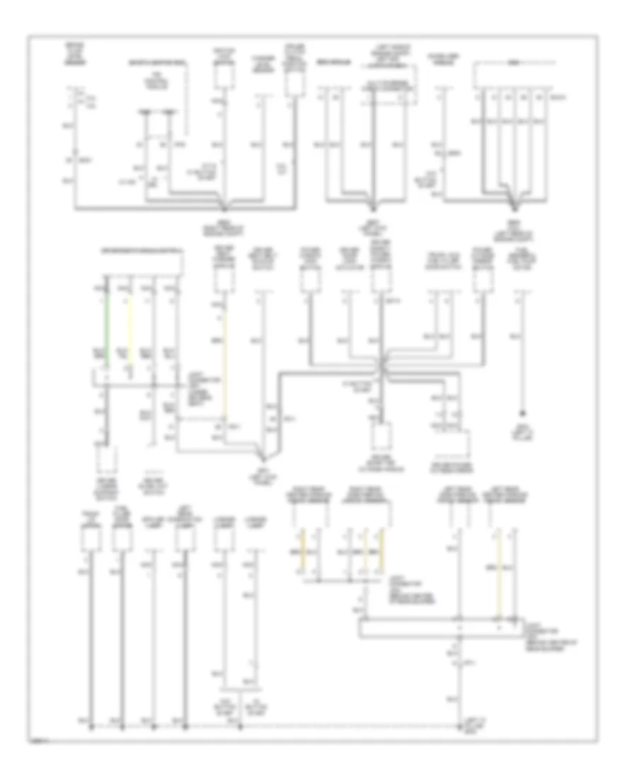 https://portal-diagnostov.com/license.html
Automotive Electricians Portal FZCO
Automotive Electricians Portal FZCO
https://portal-diagnostov.com/license.html
https://portal-diagnostov.com/license.html
Automotive Electricians Portal FZCO
Automotive Electricians Portal FZCOList of elements for Ground Distribution Wiring Diagram (3 of 4) for Hyundai Genesis Coupe 2.0T Premium 2013:
- (left "c" pillar) gf04
- (left side of engine compt)
- 2.0l
- 2.0l m/t
- 3.8l
- Brake fluid level sensor
- Cruise clutch pedal position switch
- D07-a
- Driver door lock actuator
- Driver lumbar support switch
- Driver power outside mirror
- Driver safety power window module
- Driver seat belt buckle switch
- Driver seat manual switch
- Driver seat warmer module
- Driver slide limit switch
- Driver smart key outside handle
- Ec21
- Ecm
- Elg-a
- Em51
- Esc module
- Fd11
- Ff11
- Fs11
- Fuel filler door motor
- Fuel sender & fuel pump motor
- Ge05 (right rear of engine compt)
- Ge07 (left kick panel)
- Ge08 (3.8l) (left rear of engine compt)
- Gf01 (left kick panel)
- Gf03 (left "c" pillar)
- Gnd
- I/p-e
- Ignition lock switch
- Immobilizer module
- Ips control module
- Joint connector jf03 (behind center of rear bumper)
- Joint connector jf04 (behind center of rear bumper)
- Joint connector js01 (under driver's seat)
- Left e/r junction box
- Left rear center parking assist sensor
- Left rear combination lamp
- Left rear side parking assist sensor
- License lamp
- M/t & w/ button start
- Multi-purpose check connector
- Nca
- Power outside mirror switch
- Power window main switch
- Right rear center parking assist sensor
- Right rear side parking assist sensor
- Smart junction box
- Spoiler lamp
- Trunk lid & fuel filler door switch
- Trunk lid latch
- W/ button start
- W/ drl
- W/ hid
- W/o button start
- Washer level sensor
Ground Distribution Wiring Diagram (4 of 4) for Hyundai Genesis Coupe 2.0T Premium 2013
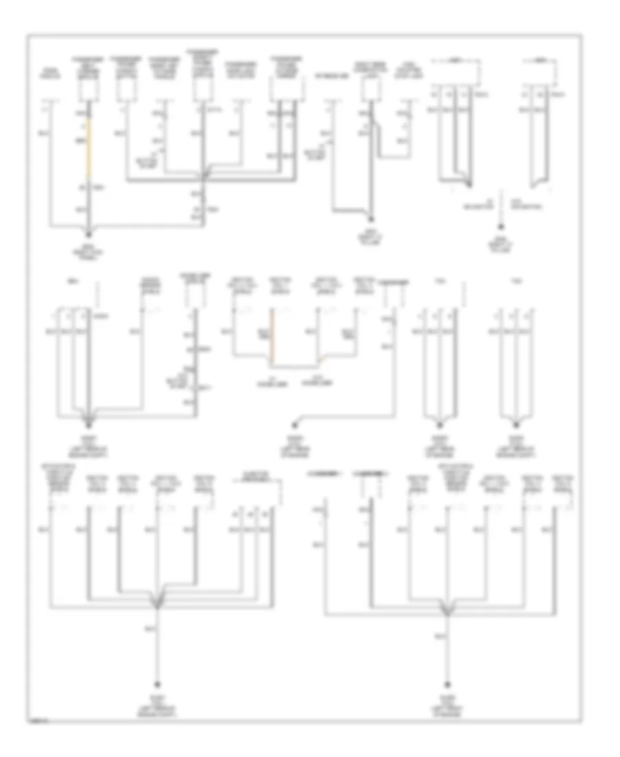 https://portal-diagnostov.com/license.html
Automotive Electricians Portal FZCO
Automotive Electricians Portal FZCO
https://portal-diagnostov.com/license.html
https://portal-diagnostov.com/license.html
Automotive Electricians Portal FZCO
Automotive Electricians Portal FZCOList of elements for Ground Distribution Wiring Diagram (4 of 4) for Hyundai Genesis Coupe 2.0T Premium 2013:
- Amp
- Chg-k
- Condenser
- Condenser 1
- Condenser 2
- D17-a
- Ec11
- Ecm
- Em51
- Etc motor & throttle position sensor shield
- F03-a
- F04-a
- Fd21
- Fs21
- Gf05 (right kick panel)
- Gf07 (right "c" pillar)
- Gf08 (right "c" pillar)
- Ghg01 (2.0l) (left rear of engine compt)
- Ghg02 (2.0l) (left rear of engine)
- Ghg03 (2.0l) (left rear of engine)
- Glg01 (3.8l) (left rear of engine compt)
- Glg02 (3.8l) (left front of engine)
- Glg03 (3.8l) (left rear of engine compt)
- High mounted stop lamp
- Ignition coil 1 shield
- Ignition coil 1, 2 & 3 shield
- Ignition coil 1, 3 & 5 shield
- Ignition coil 2 shield
- Ignition coil 2, 3 & 4 shield
- Ignition coil 4 shield
- Ignition coil 6 shield
- Immobilizer module
- Injector drive box
- Knock sensor shield
- Nca
- Passenger door lock actuator
- Passenger power outside mirror
- Passenger power window switch
- Passenger safety power window module
- Passenger seat warmer module
- Passenger smart key outside handle
- Pods module
- Rf receiver
- Right rear combination lamp
- Tcm
- W/ button start
- W/ immobilizer
- W/ navigation
- W/o button start
- W/o immobilizer
- W/o navigation
HEADLIGHTS
Autolamps Wiring Diagram for Hyundai Genesis Coupe 2.0T Premium 2013
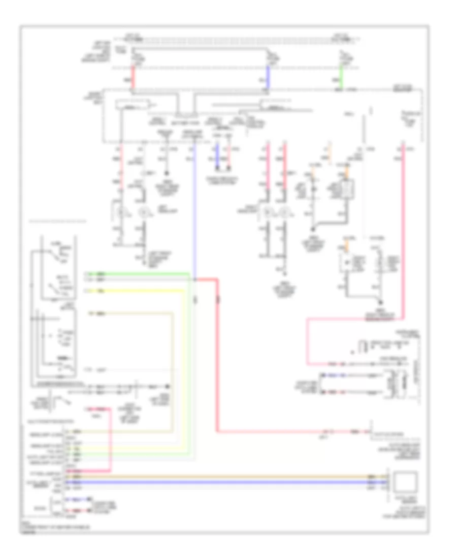 https://portal-diagnostov.com/license.html
Automotive Electricians Portal FZCO
Automotive Electricians Portal FZCO
https://portal-diagnostov.com/license.html
https://portal-diagnostov.com/license.html
Automotive Electricians Portal FZCO
Automotive Electricians Portal FZCOList of elements for Autolamps Wiring Diagram for Hyundai Genesis Coupe 2.0T Premium 2013:
- (hid)
- (left front of engine compt) ge03
- (right rear of engine compt)
- Arisu 1
- Arisu 1 control
- Arisu 2
- Arisu 2 control b-can
- Auto
- Auto headlamp leveling device unit (left rear suspension)
- Auto light & photo sensor (top center of dash)
- Auto light sensor
- Auto light sw on
- B+1 fuse 60a
- B+2 fuse 60a
- B+3 fuse 60a
- B-can
- Battery pwr
- Bcm (under front of center console)
- Computer data lines system
- Dimmer/passing switch
- Ee11
- Front fog lamp ind
- Front fog lamp switch
- Ft fog lamp sw
- Ge02
- Ge03 (left front of engine compt)
- Ge05 (right rear of engine compt)
- Gm02 (left side of dash)
- Gnd
- Ground
- H/lp (lo) on sig
- Head
- Headlamp hi sw
- Headlamp lo sig
- Headlamp lo sw
- Headlamp low signal
- High
- High beam ind
- Hot at all times
- Hot in on or start
- I/p-c
- I/p-d
- I/p-e
- Instrument cluster
- Ips 2
- Ips 2 control
- Ips control module
- Joint connector jm01 (left side of dash)
- Led drive ic
- Left drl & fog lamp
- Left e/r junction box (left side of engine compt)
- Left front fog lamp
- Left headlamp
- Light switch
- Low
- M02-a
- M02-b
- M02-c
- M48-l
- Mf11
- Micom
- Module fuse 7.5a
- Multi fuse
- Multi-function switch
- Nca
- Off
- Pass
- Pnk
- Pwr
- Red
- Right drl & fog lamp
- Right front fog lamp
- Right headlamp
- Rl ic
- Sig
- Smart junction box
- Tail
- Tail sw
- Transceiver b-can
- W/ drl
- W/o drl
Headlamps Wiring Diagram (1 of 2) for Hyundai Genesis Coupe 2.0T Premium 2013
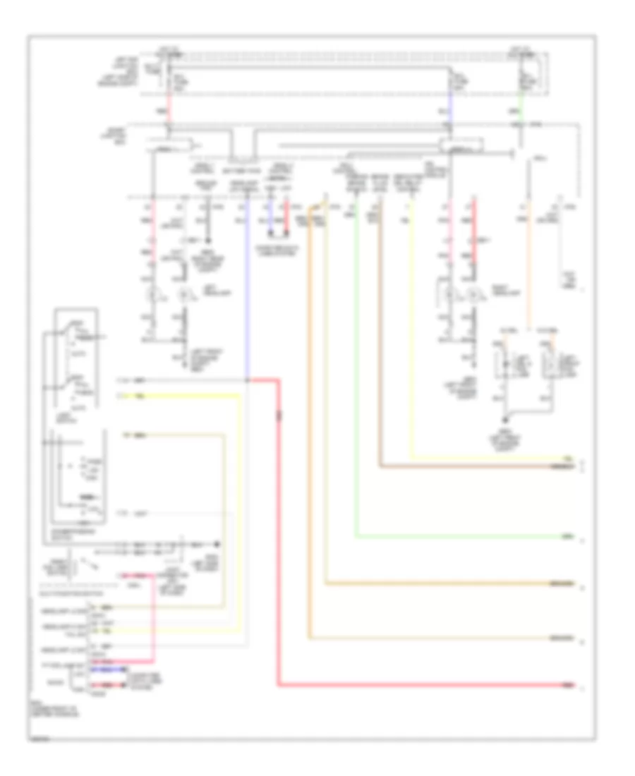 https://portal-diagnostov.com/license.html
Automotive Electricians Portal FZCO
Automotive Electricians Portal FZCO
https://portal-diagnostov.com/license.html
https://portal-diagnostov.com/license.html
Automotive Electricians Portal FZCO
Automotive Electricians Portal FZCOList of elements for Headlamps Wiring Diagram (1 of 2) for Hyundai Genesis Coupe 2.0T Premium 2013:
- (hid)
- (left front of engine compt) ge03
- Arisu 1
- Arisu 1 control
- Arisu 2
- Arisu 2 control
- Auto
- B+1 fuse 60a
- B+2 fuse 60a
- B+3 fuse 60a
- B-can
- Battery pwr
- Bcm (under front of center console)
- Brake
- Brake switch
- Computer data lines system
- Dedicated
- Dimmer/passing switch
- Drl relay control
- Ee11
- Fluid level
- Front fog lamp switch
- Ft fog lamp sw
- Ge03 (left front of engine compt)
- Ge05 (right rear of engine compt)
- Gm02 (left side of dash)
- Ground
- Head
- Headlamp hi sw
- Headlamp lo sig
- Headlamp lo sw
- Headlamp low signal
- High
- Hot at all times
- I/p-d
- I/p-e
- I/p-g
- Ips 2
- Ips 2 control
- Ips control module
- Joint connector jm01 (left side of dash)
- Left drl & fog lamp
- Left e/r junction box (left side of engine compt)
- Left front fog lamp
- Left headlamp
- Light switch
- Low
- M02-a
- M02-b
- M02-c
- M48-l
- Multi fuse
- Multi-function switch
- Nca
- Off
- Parking
- Pass
- Pnk
- Red
- Right headlamp
- Smart junction box
- Tail
- Tail sw
- W/ drl
- W/o drl
Headlamps Wiring Diagram (2 of 2) for Hyundai Genesis Coupe 2.0T Premium 2013
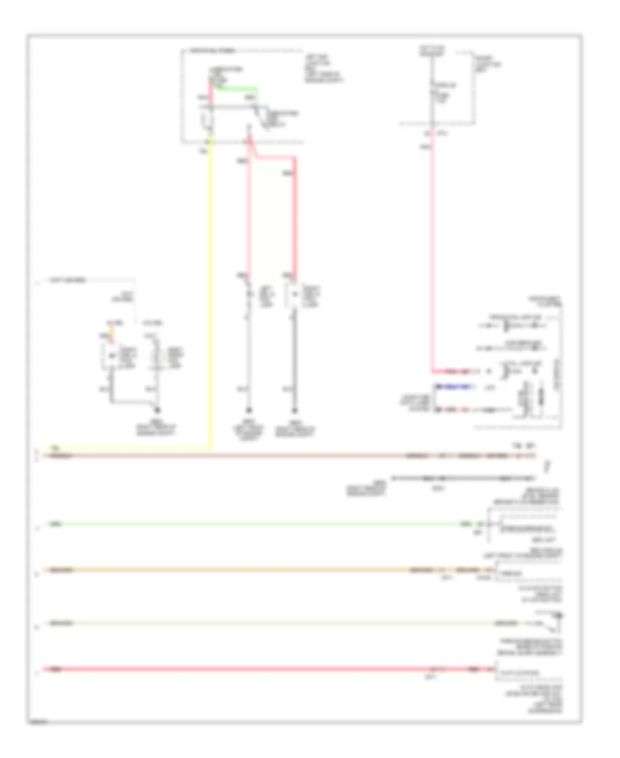 https://portal-diagnostov.com/license.html
Automotive Electricians Portal FZCO
Automotive Electricians Portal FZCO
https://portal-diagnostov.com/license.html
https://portal-diagnostov.com/license.html
Automotive Electricians Portal FZCO
Automotive Electricians Portal FZCOList of elements for Headlamps Wiring Diagram (2 of 2) for Hyundai Genesis Coupe 2.0T Premium 2013:
- 2.0l
- 3.8l
- Auto headlamp leveling device unit (w/ hid) (left rear suspension)
- Av & navigation head unit (w/ navigation)
- Brake fluid level sensor (brake fluid reservoir)
- Computer data lines system
- Dedicated drl fuse 10a
- Dedicated drl relay
- E51
- Ec21
- Esc module (left front of engine compt)
- Esc unit
- Front fog lamp ind
- Ge02 (right rear of engine compt)
- Ge03 (left front of engine compt)
- Ge05 (right rear of engine compt)
- H/lp (lo) on sig
- High
- High beam ind
- Hot at all times
- Hot in on or start
- I/p-c
- Instrument cluster
- Led drive ic
- Left drl & fog lamp
- Left e/r junction box (left side of engine compt)
- Low
- M70-b
- Mf11
- Micom
- Module fuse 7.5a
- Parking
- Parking brake sw
- Parking brake switch (base of parking brake lever assembly)
- Pnk
- Red
- Right drl & fog lamp
- Right front fog lamp
- Rl ic
- Smart junction box
- Tail lamp ind
- Transceiver b-can
- W/ drl
- W/o drl
Headlamps Leveling Wiring Diagram for Hyundai Genesis Coupe 2.0T Premium 2013
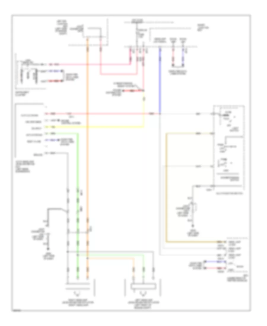 https://portal-diagnostov.com/license.html
Automotive Electricians Portal FZCO
Automotive Electricians Portal FZCO
https://portal-diagnostov.com/license.html
https://portal-diagnostov.com/license.html
Automotive Electricians Portal FZCO
Automotive Electricians Portal FZCOList of elements for Headlamps Leveling Wiring Diagram for Hyundai Genesis Coupe 2.0T Premium 2013:
- (left front of engine compt)
- (left rear
- (left side
- (left side of engine
- (right headlamp)
- (under front of center console)
- Actuator sig
- Assist system
- Auto
- Auto headlamp leveling device
- B-can
- B-can high
- B-can low
- Bcm
- Body k-line
- Box
- Cluster
- Compt)
- Computer
- Computer data lines system
- Connector
- Control system
- Cruise
- Data lines
- Dimmer/passing switch
- Ee11
- Em21
- Gm02 (left side of dash)
- Ground
- H/lp (lo) on sig
- Head
- Head lamp
- Headlamp low signal
- Hi sw
- High
- High beam ind
- Hot in on or start
- I/p-c
- I/p-d
- I/p-e
- I/p-g
- Instrument
- Je70
- Jm01
- Joint
- Junction
- Led drive ic
- Left e/r junction
- Left headlamp leveling device actuator
- Light switch
- Lo sig
- Lo sw
- Low
- M02-a
- M02-b
- M02-c
- M48-l
- Mf11
- Micom
- Module fuse 7.5a
- Multi-function switch
- Of dash)
- Off
- On input
- Pass
- Pnk
- Power distribution system
- Red
- Right headlamp leveling device actuator
- Smart
- Suspension)
- System
- Tail
- Tranceiver b-can
- Unit
- Veh spd sens
- W/ rear parking
HORN
Horn Wiring Diagram for Hyundai Genesis Coupe 2.0T Premium 2013
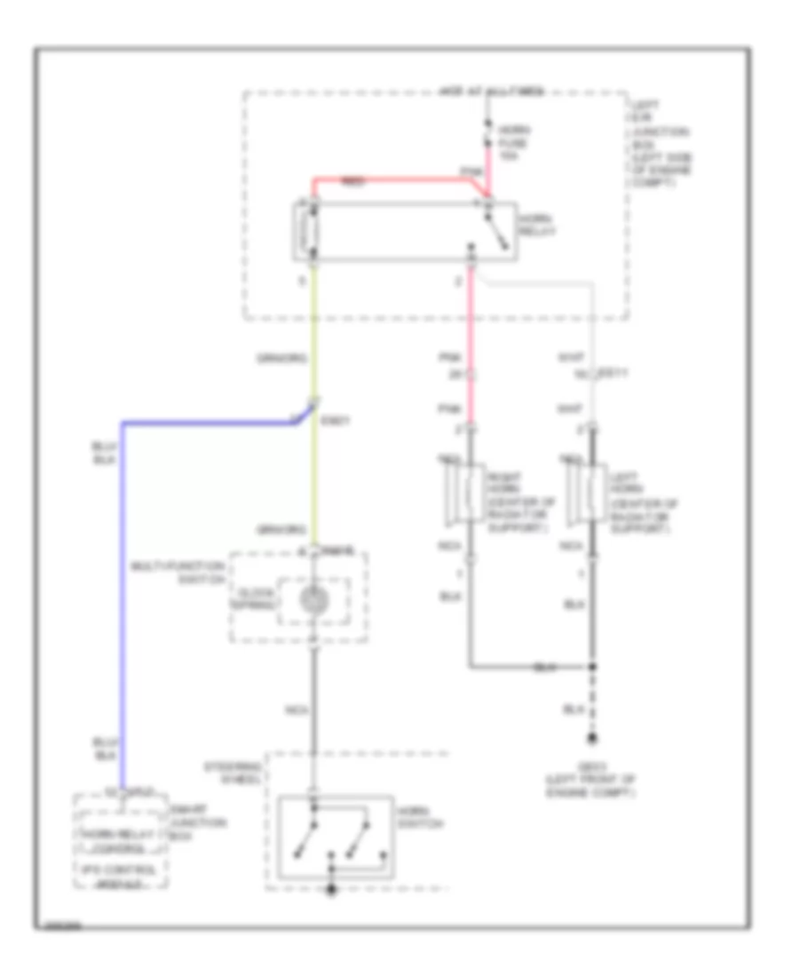 https://portal-diagnostov.com/license.html
Automotive Electricians Portal FZCO
Automotive Electricians Portal FZCO
https://portal-diagnostov.com/license.html
https://portal-diagnostov.com/license.html
Automotive Electricians Portal FZCO
Automotive Electricians Portal FZCOList of elements for Horn Wiring Diagram for Hyundai Genesis Coupe 2.0T Premium 2013:
- (center of radiator support)
- Clock spring
- Ee11
- Em21
- Ge03 (left front of engine compt)
- Horn fuse 15a
- Horn relay
- Horn relay control
- Horn switch
- Hot at all times
- I/p-d
- Ips control module
- Junction box (left side of engine compt)
- Left e/r
- Left horn
- M48-r
- Multi-function switch
- Nca
- Pnk
- Red
- Right horn (center of radiator support)
- Smart junction box
- Steering wheel
INSTRUMENT CLUSTER
Instrument Cluster Wiring Diagram (1 of 2) for Hyundai Genesis Coupe 2.0T Premium 2013
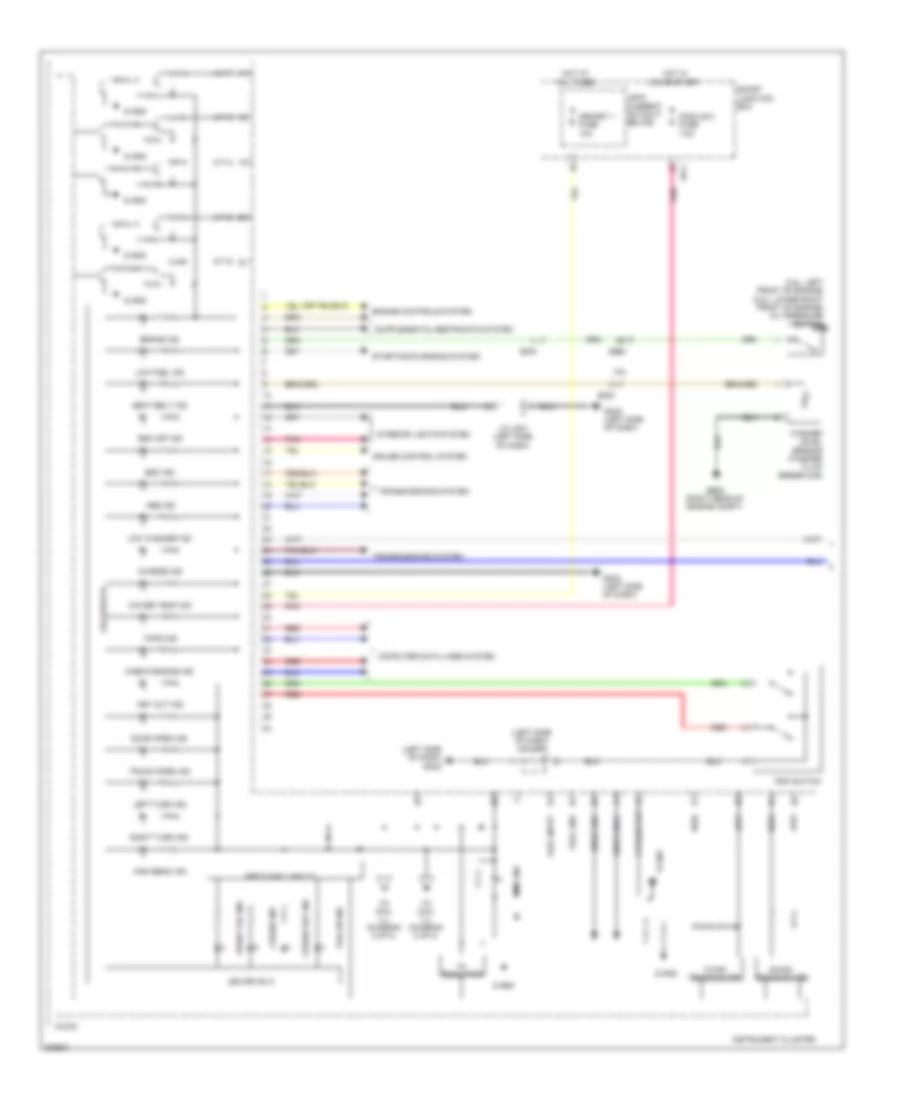 https://portal-diagnostov.com/license.html
Automotive Electricians Portal FZCO
Automotive Electricians Portal FZCO
https://portal-diagnostov.com/license.html
https://portal-diagnostov.com/license.html
Automotive Electricians Portal FZCO
Automotive Electricians Portal FZCOList of elements for Instrument Cluster Wiring Diagram (1 of 2) for Hyundai Genesis Coupe 2.0T Premium 2013:
- (3.8l: left front of engine) (2.0l: lower right front of engine) oil pressure switch
- (left side of dash) gm02
- (left side of dash) j/c jm01
- 3.8l
- 4 pulse out
- 5v regulator
- A/t d
- A/t n
- A/t p
- A/t r
- A/t s
- Abs ind
- B-can transceiver
- Brake ind
- C-can transceiver
- Charge ind
- Check engine ind
- Computer data lines system
- Cruise control system
- Cruise ind
- Cruise set ind
- Door open ind
- Ec21
- Em51
- Engine controls system
- Esc ind
- Esc off ind
- Front fog ind
- Fuel gnd
- Fuel input
- Ge05 (right rear of engine compt)
- Gm02 (left side of dash)
- High
- High beam ind
- Hot at all times
- Hot in on or start
- I/p-c
- Immo ind
- Instrument cluster
- Interior lights system
- J/c jm01 (left side of dash)
- Key out ind
- Leak current autocut device
- Led drive ic
- Left turn ind
- Low
- Low fuel ind
- Low washer ind
- Memory 1 fuse 10a
- Micom
- Module 2 fuse 7.5a
- Pnk
- Red
- Reducing light ic
- Right turn ind
- S gnd
- Seat belt ind
- Smart junction box
- Snse gnd
- Snse gnd2
- Starting/charging system
- Tail on ind
- Tmps ind
- To dial ill (diagram 2 of 2)
- Transmissions system
- Trip switch
- Trunk open ind
- Washer level sensor (washer fluid reservoir)
- Water temp ind
Instrument Cluster Wiring Diagram (2 of 2) for Hyundai Genesis Coupe 2.0T Premium 2013
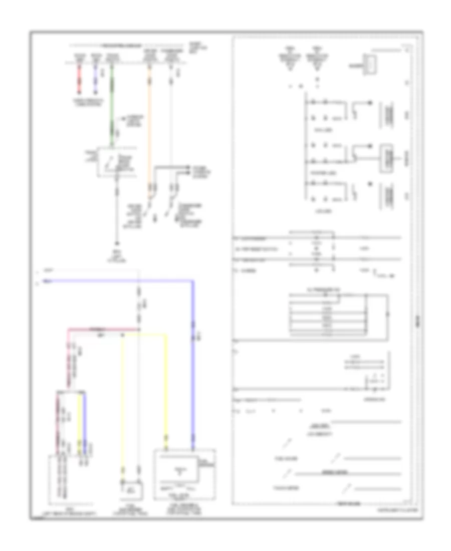 https://portal-diagnostov.com/license.html
Automotive Electricians Portal FZCO
Automotive Electricians Portal FZCO
https://portal-diagnostov.com/license.html
https://portal-diagnostov.com/license.html
Automotive Electricians Portal FZCO
Automotive Electricians Portal FZCOList of elements for Instrument Cluster Wiring Diagram (2 of 2) for Hyundai Genesis Coupe 2.0T Premium 2013:
- (+)
- (-)
- (left "c" pillar)
- 2.0l
- 3.8l
- Air bag ind
- B-can high
- B-can low
- Buzzer
- Charge
- Chg-k
- Computer data lines system
- Current constant
- Dail
- Dial (led)
- Driver door switch
- Driver door switch (on driver "b" pillar)
- Ec11
- Ecm (left rear of engine compt)
- Elg-a
- Empty
- From 5v regulator (diagram 1 of 2)
- Fuel gauge
- Fuel level float
- Fuel sender
- Fuel sender & fuel pump motor (top of fuel tank)
- Fuel sub sender (top of fuel tank)
- Full
- Gf04
- I/p-d
- I/p-g
- Ill (+)
- Ill (-)
- Instrument cluster
- Interior lights system
- Ips control module
- Lcd
- Lcd (led)
- Lcd (seg/dot)
- Low washer
- Mf11
- Mf31
- Micom
- Middle fuel level sig
- Odo trip
- Oil pressure ind
- Passenger door switch
- Passenger door switch (on passenger "b" pillar)
- Pointer
- Pointer (led)
- Power windows system
- Red
- Sig 1
- Sig 2
- Smart junction box
- Speed meter
- Tacho meter
- Temp gauge
- Total fuel level sig
- Trip reset switch
- Trip switch
- Trunk lid latch
- Trunk room lamp switch
- Trunk switch
INTERIOR LIGHTS
Courtesy Lamps Wiring Diagram for Hyundai Genesis Coupe 2.0T Premium 2013
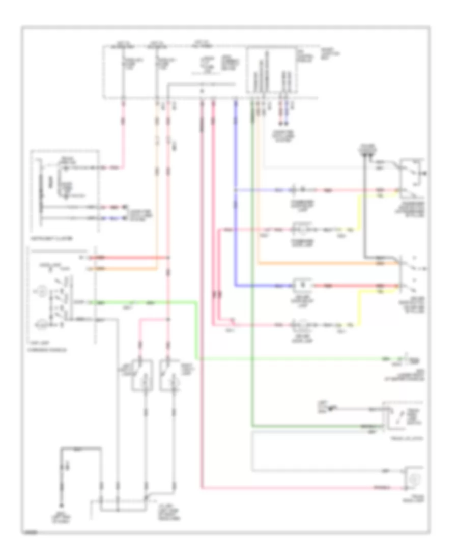 https://portal-diagnostov.com/license.html
Automotive Electricians Portal FZCO
Automotive Electricians Portal FZCO
https://portal-diagnostov.com/license.html
https://portal-diagnostov.com/license.html
Automotive Electricians Portal FZCO
Automotive Electricians Portal FZCOList of elements for Courtesy Lamps Wiring Diagram for Hyundai Genesis Coupe 2.0T Premium 2013:
- (left "c" pillar)
- B-can high
- B-can low
- B-can transceiver
- Bcm (under front of center console)
- Computer data lines system
- Door
- Door open ind
- Driver door lamp
- Driver door scuff lamp
- Driver door sw
- Driver door switch (on driver "b" pillar)
- Fd11
- Fd21
- Gf04
- Gm01 (left end of dash)
- Gnd
- High
- Hot at all times
- Hot in acc or on
- Hot in on or start
- I/p-c
- I/p-d
- I/p-g
- Instrument cluster
- Ips control module
- J/c jr01 (left side of front headliner)
- Leak current autocut device
- Led device ic
- Left vanity lamp
- Low
- M02-c
- Map lamp
- Micom
- Module 1 fuse 7.5a
- Module 2 fuse 7.5a
- Mood lamp
- Mr11
- Off
- Overhead console
- Passenger door lamp
- Passenger door scuff lamp
- Passenger door sw
- Passenger door switch (on passenger "b" pillar)
- Pnk
- Power windows system
- Red
- Right vanity lamp
- Room lamp
- Room lp fuse 10a
- Smart junction box
- Trunk lid latch
- Trunk open ind
- Trunk room lamp
- Trunk room lamp switch
- Trunk sw
Instrument Illumination Wiring Diagram (1 of 2) for Hyundai Genesis Coupe 2.0T Premium 2013
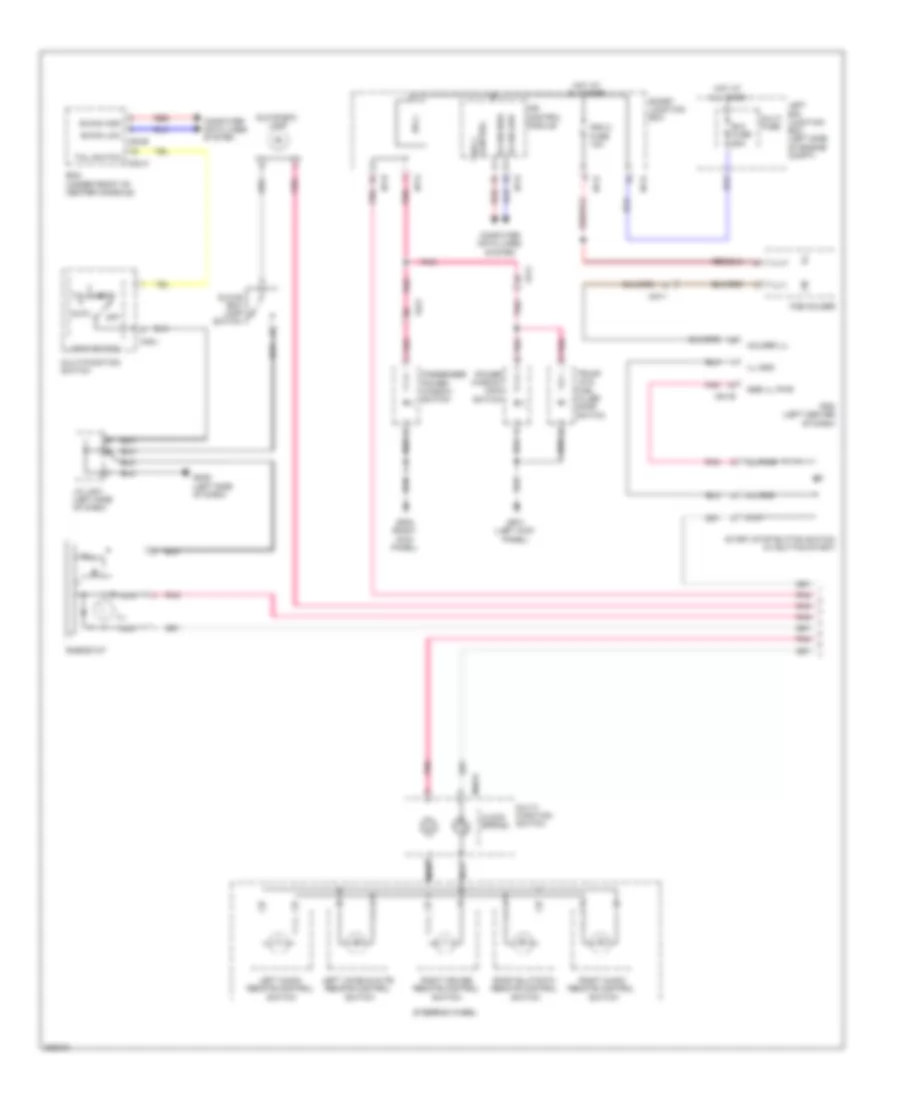 https://portal-diagnostov.com/license.html
Automotive Electricians Portal FZCO
Automotive Electricians Portal FZCO
https://portal-diagnostov.com/license.html
https://portal-diagnostov.com/license.html
Automotive Electricians Portal FZCO
Automotive Electricians Portal FZCOList of elements for Instrument Illumination Wiring Diagram (1 of 2) for Hyundai Genesis Coupe 2.0T Premium 2013:
- Auto
- B+2 fuse 60a
- B-can high
- B-can low
- Bcm (under front of center console)
- Clock spring
- Computer data lines system
- Control ips 1
- Fd11
- Fd21
- Fob holder
- Gf01 (left kick panel)
- Gf05 (right kick panel)
- Glove box lamp
- Glove box lamp switch
- Gm02 (left side of dash)
- Head
- Holder ill
- Hot at all times
- I/p-b
- I/p-d
- I/p-e
- I/p-g
- Ill
- Ill gnd
- Ill pwr
- Ill(+)
- Ill(-)
- Ips 1
- Ips control module
- J/c jm01 (left side of dash)
- Left audio remote control switch
- Left e/r junction box (left side of engine compt)
- Left voice & mute remote control switch
- Light switch
- M02-a
- M02-b
- M48-l
- M48-r
- M51-b
- Mm11
- Multi fuse
- Multi- function switch
- Multi-function switch
- Nca
- Off
- Passenger power window switch
- Pdm (left center of dash)
- Pdm 2 fuse 10a
- Pnk
- Power window main switch
- Red
- Rheostat
- Right audio remote control switch
- Right cruise remote control switch
- Smart junction box
- Ssb ill pwr
- Start stop button switch (w/ button start)
- Steering wheel
- Tail
- Tail switch
- Trunk lid & fuel filler door switch
Instrument Illumination Wiring Diagram (2 of 2) for Hyundai Genesis Coupe 2.0T Premium 2013
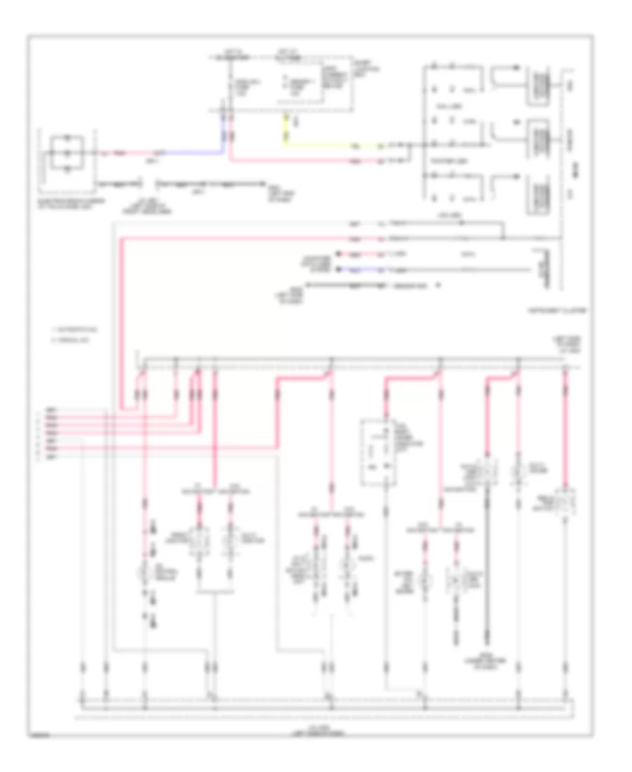 https://portal-diagnostov.com/license.html
Automotive Electricians Portal FZCO
Automotive Electricians Portal FZCO
https://portal-diagnostov.com/license.html
https://portal-diagnostov.com/license.html
Automotive Electricians Portal FZCO
Automotive Electricians Portal FZCOList of elements for Instrument Illumination Wiring Diagram (2 of 2) for Hyundai Genesis Coupe 2.0T Premium 2013:
- (left side of dash) j/c jm02
- A/c control module
- Atm shift lever indicator (a/t)
- Audio
- Automatic a/c
- Aux & usb jack
- Aux & usb jack (w/o navigation)
- Av & navi- gation head unit
- B-can transceiver
- Computer data lines system
- Constant
- Current voltage constant
- Dial
- Dial (led)
- Electrochromic mirror (w/ tmu & home link)
- Esc & pas switch
- Exter- nal key- board
- Front monitor
- Gm01 (left end of dash)
- Gm02 (left side of dash)
- Gm05 (under center of dash)
- High
- Hot at all times
- Hot in on or start
- I/p-c
- Ill (+)
- Ill (-)
- Instrument cluster
- J/c jm02 (left side of dash)
- J/c jr01 (left side of front headliner)
- Lcd
- Lcd (led)
- Leak current autocut device
- Low
- M03-a
- M06-a
- M07-a
- M70-a
- Manual a/c
- Memory 1 fuse 10a
- Micom
- Module 2 fuse 7.5a
- Mr11
- Multi gauge
- Multi monitor
- Pnk
- Pointer
- Pointer (led)
- Red
- Sensor gnd
- Smart junction box
- Voltage current
- W/ navigation
- W/o navigation
NAVIGATION
Mobile Telematic System Wiring Diagram for Hyundai Genesis Coupe 2.0T Premium 2013
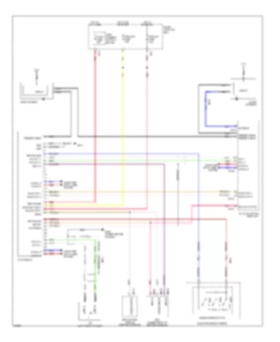 https://portal-diagnostov.com/license.html
Automotive Electricians Portal FZCO
Automotive Electricians Portal FZCO
https://portal-diagnostov.com/license.html
https://portal-diagnostov.com/license.html
Automotive Electricians Portal FZCO
Automotive Electricians Portal FZCOList of elements for Mobile Telematic System Wiring Diagram for Hyundai Genesis Coupe 2.0T Premium 2013:
- (left front of roof)
- A/bag
- A/v & navigation head unit
- Acc/on input
- Antenna
- Audio fuse 15a
- Audio o/p (+)
- Audio o/p (-)
- Bcm (under front of center console)
- Bcm rx
- Bcm tx
- C-can hi
- C-can lo
- Circuit
- Computer
- Computer data lines system
- Crash output
- Crash unlock
- Data lines
- Dr unlk state
- Electrochromic mirror
- Feeder cable
- Fuse 7.5a
- Glass antenna
- Gm05 (under center of dash)
- Gm11
- Gnd
- Hot at all times
- Hot in on or acc
- Hot in on or start
- I/p-a
- I/p-c
- Inside mirror switch
- Keypad gnd
- Keypad sig
- Leak current autocut device
- M-can hi
- M-can lo
- M02-a
- M02-b
- M02-c
- M70-a
- M70-b
- M70-c
- M71-a
- Mem power
- Mf31
- Mic
- Mic (+)
- Mic (-)
- Mic in (+)
- Mic in (-)
- Mic out (+)
- Mic out (-)
- Mic shield
- Module 1
- Module 2 fuse 7.5a
- Mr11
- Mts module
- Mts rx
- Mts tx
- Nca
- On/start input
- Pnk
- Red
- Roof antenna
- Smart junction box
- Srs control module (center console)
- Sw1
- Sw2
- Sw3
- System
Navigation Wiring Diagram, with JBL Amplifier (1 of 3) for Hyundai Genesis Coupe 2.0T Premium 2013
 https://portal-diagnostov.com/license.html
Automotive Electricians Portal FZCO
Automotive Electricians Portal FZCO
https://portal-diagnostov.com/license.html
https://portal-diagnostov.com/license.html
Automotive Electricians Portal FZCO
Automotive Electricians Portal FZCOList of elements for Navigation Wiring Diagram, with JBL Amplifier (1 of 3) for Hyundai Genesis Coupe 2.0T Premium 2013:
- (+)
- (-)
- A/v & navigation head unit
- Acc/on i/p
- Alt l
- Antenna
- Anti-lock brakes system
- Audio (+)
- Audio (-)
- Audio (-) call end of
- Audio (-) vol up
- Audio fuse 15a
- Auto light state
- Aux detect
- Aux gnd
- Aux l in
- Aux r in
- B/t (in)
- B/t (out)
- Bcm (under front of center console)
- Call
- Circuit
- Clock spring
- Computer data lines system
- Cruise control system
- Down seek
- Dr unlk state
- Exterior lights system
- Feeder cable
- Glass antenna
- Gm05 (under center of dash)
- Gnd
- Hot at all times
- I/p-a
- Ill
- Ill (+)
- Ill (-)
- Interior lights system
- Ipod vod sig
- Leak current autocut device
- Left audio remote control switch
- Left voice & mute remote control switch
- M-can high
- M-can low
- M02-c
- M48-r
- M70-a
- M70-b
- Mem power
- Mf31
- Mic (+)
- Mic (-)
- Mode
- Multi-function switch (remote control)
- Mute
- Mute (in)
- Navi voice (+)
- Navi voice (-)
- Nca
- Parking
- Pnk
- Red
- Reverse sig
- Right audio remote control switch
- Sig
- Smart junction box
- Spdif gnd
- Spdif out (+)
- Spdif out (-)
- Starting/charging system
- Steering wheel
- Up seek
- V gnd
- Veh spd sig
- Voice
- Voice (in)
- Voice (out)
- Vol (in)
- Vol (out)
- Vol dw
Navigation Wiring Diagram, with JBL Amplifier (2 of 3) for Hyundai Genesis Coupe 2.0T Premium 2013
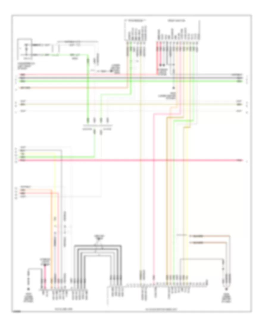 https://portal-diagnostov.com/license.html
Automotive Electricians Portal FZCO
Automotive Electricians Portal FZCO
https://portal-diagnostov.com/license.html
https://portal-diagnostov.com/license.html
Automotive Electricians Portal FZCO
Automotive Electricians Portal FZCOList of elements for Navigation Wiring Diagram, with JBL Amplifier (2 of 3) for Hyundai Genesis Coupe 2.0T Premium 2013:
- (under center of dash) gm05
- A/v & navigation head unit
- Acc/on i/p
- Audio o/p (+)
- Audio o/p (-)
- Aux & usb jack
- Aux det
- Aux gnd
- Aux l in
- Aux r in
- Bcm rx
- Bl on
- Front monitor
- Gm05
- Gm05 (under center of dash)
- Gnd
- Handsfree mic (left front of roof)
- Ill (+)
- Ill(+)
- Ill(-)
- Interior lights system
- Lvds lock
- Lvds pdn
- M70-c
- Mem pwr
- Mic (+)
- Mic (-)
- Mic out (+)
- Mic out (-)
- Mic shld
- Mts module
- Nca
- Pnk
- Red
- Rx (+)
- Rx (-)
- Tx (+)
- Tx (-)
- Usb d (+)
- Usb d (-)
- Usb gnd
- Usb high cable
- Usb vcc
- V gnd
- Vod out
- W/ mts
- W/o mts
Navigation Wiring Diagram, with JBL Amplifier (3 of 3) for Hyundai Genesis Coupe 2.0T Premium 2013
 https://portal-diagnostov.com/license.html
Automotive Electricians Portal FZCO
Automotive Electricians Portal FZCO
https://portal-diagnostov.com/license.html
https://portal-diagnostov.com/license.html
Automotive Electricians Portal FZCO
Automotive Electricians Portal FZCOList of elements for Navigation Wiring Diagram, with JBL Amplifier (3 of 3) for Hyundai Genesis Coupe 2.0T Premium 2013:
- Acc/on input
- Amp (right quarterpanel)
- Amp fuse 25a
- Batt pwr
- Center speaker
- Center speaker (+)
- Center speaker (-)
- Computer data lines system
- Driver door speaker
- Driver door tweeter speaker
- F04-a
- F04-b
- Fd11
- Fd21
- Fl (+)
- Fl (-)
- Fr (+)
- Fr (-)
- Gf08 (right "c" pillar)
- Gnd
- Hot at all times
- Hot in on or acc
- I/p-c
- I/p-f
- I/p-g
- Left rear speaker
- M-can high
- M-can low
- Mf31
- Module fuse 7.5a
- Navi voice (+)
- Navi voice (-)
- Nca
- Passenger door speaker
- Passenger door tweeter speaker
- Pnk
- Red
- Right rear speaker
- Rl (+)
- Rl (-)
- Rr (+)
- Rr (-)
- Smart junction box
- Spdif out (+)
- Spdif out (-)
- Sub woofer
- Sub woofer 1 (+)
- Sub woofer 1 (-)
- Sub woofer 2 (+)
- Sub woofer 2 (-)
Navigation Wiring Diagram, without JBL Amplifier (1 of 3) for Hyundai Genesis Coupe 2.0T Premium 2013
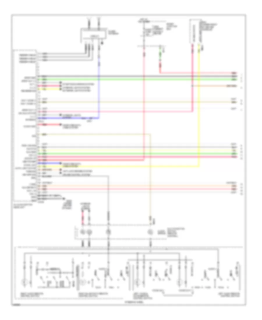 https://portal-diagnostov.com/license.html
Automotive Electricians Portal FZCO
Automotive Electricians Portal FZCO
https://portal-diagnostov.com/license.html
https://portal-diagnostov.com/license.html
Automotive Electricians Portal FZCO
Automotive Electricians Portal FZCOList of elements for Navigation Wiring Diagram, without JBL Amplifier (1 of 3) for Hyundai Genesis Coupe 2.0T Premium 2013:
- (+)
- (-)
- A/v & navigation head unit
- Acc/on i/p
- Alt l
- Antenna
- Anti-lock brakes system
- Audio (+)
- Audio (-)
- Audio (-) call end of
- Audio (-) vol up
- Audio fuse 15a
- Auto light state
- Aux detect
- Aux gnd
- Aux l in
- Aux r in
- B/t (in)
- B/t (out)
- Bcm (under front of center console)
- Call
- Circuit
- Clock spring
- Computer data lines system
- Cruise control system
- Down seek
- Dr unlk state
- Exterior lights system
- Feeder cable
- Glass antenna
- Gm05 (under center of dash)
- Gnd
- Hot at all times
- I/p-a
- Ill
- Ill (+)
- Ill (-)
- Interior lights system
- Ipod vod sig
- Leak current autocut device
- Left audio remote control switch
- Left voice & mute remote control switch
- M-can high
- M-can low
- M02-c
- M48-r
- M70-a
- M70-b
- Mem power
- Mf31
- Mic (+)
- Mic (-)
- Mode
- Multi-function switch (remote control)
- Mute
- Mute (in)
- Navi voice (+)
- Navi voice (-)
- Nca
- Parking
- Pnk
- Red
- Reverse sig
- Right audio remote control switch
- Sig
- Smart junction box
- Spdif gnd
- Spdif out (+)
- Spdif out (-)
- Starting/charging system
- Steering wheel
- Up seek
- V gnd
- Veh spd sig
- Voice
- Voice (in)
- Voice (out)
- Vol (in)
- Vol (out)
- Vol dw
Navigation Wiring Diagram, without JBL Amplifier (2 of 3) for Hyundai Genesis Coupe 2.0T Premium 2013
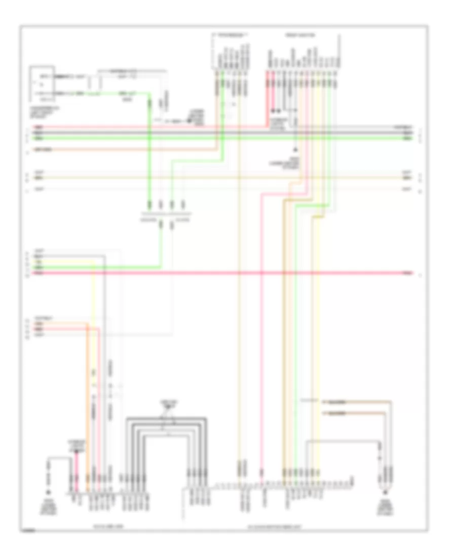 https://portal-diagnostov.com/license.html
Automotive Electricians Portal FZCO
Automotive Electricians Portal FZCO
https://portal-diagnostov.com/license.html
https://portal-diagnostov.com/license.html
Automotive Electricians Portal FZCO
Automotive Electricians Portal FZCOList of elements for Navigation Wiring Diagram, without JBL Amplifier (2 of 3) for Hyundai Genesis Coupe 2.0T Premium 2013:
- (under center of dash) gm05
- A/v & navigation head unit
- Acc/on i/p
- Audio o/p (+)
- Audio o/p (-)
- Aux & usb jack
- Aux det
- Aux gnd
- Aux l in
- Aux r in
- Bcm rx
- Bl on
- Front monitor
- Gm05
- Gm05 (under center of dash)
- Gnd
- Handsfree mic (left front of roof)
- Ill (+)
- Ill(+)
- Ill(-)
- Interior lights system
- Lvds lock
- Lvds pdn
- M70-c
- Mem pwr
- Mic (+)
- Mic (-)
- Mic out (+)
- Mic out (-)
- Mic shld
- Mts module
- Nca
- Pnk
- Red
- Rx (+)
- Rx (-)
- Tx (+)
- Tx (-)
- Usb d (+)
- Usb d (-)
- Usb gnd
- Usb high cable
- Usb vcc
- V gnd
- Vod out
- W/ mts
- W/o mts
Navigation Wiring Diagram, without JBL Amplifier (3 of 3) for Hyundai Genesis Coupe 2.0T Premium 2013
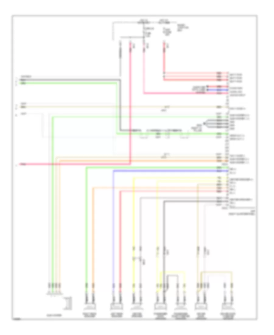 https://portal-diagnostov.com/license.html
Automotive Electricians Portal FZCO
Automotive Electricians Portal FZCO
https://portal-diagnostov.com/license.html
https://portal-diagnostov.com/license.html
Automotive Electricians Portal FZCO
Automotive Electricians Portal FZCOList of elements for Navigation Wiring Diagram, without JBL Amplifier (3 of 3) for Hyundai Genesis Coupe 2.0T Premium 2013:
- Acc/on input
- Amp (right quarterpanel)
- Amp fuse 25a
- Batt pwr
- Center speaker
- Center speaker (+) fr (+)
- Center speaker (-) fr (-)
- Computer data lines system
- Driver door speaker
- Driver door tweeter speaker
- F03-a
- F03-c
- Fd11
- Fd21
- Fl (+)
- Fl (-)
- Gf08 (right "c" pillar)
- Gnd
- Hot at all times
- Hot in on or acc
- I/p-c
- I/p-f
- I/p-g
- Left rear speaker
- M-can high
- M-can low
- Mf31
- Module fuse 7.5a
- Navi voice (+)
- Navi voice (-)
- Nca
- Passenger door speaker
- Passenger door tweeter speaker
- Pnk
- Red
- Right rear speaker
- Rl (+)
- Rl (-)
- Rr (+)
- Rr (-)
- Smart junction box
- Spdif out (+)
- Spdif out (-)
- Sub woofer
- Sub woofer 1 (+)
- Sub woofer 1 (-)
- Sub woofer 2 (+)
- Sub woofer 2 (-)
Parking Assistant Wiring Diagram for Hyundai Genesis Coupe 2.0T Premium 2013
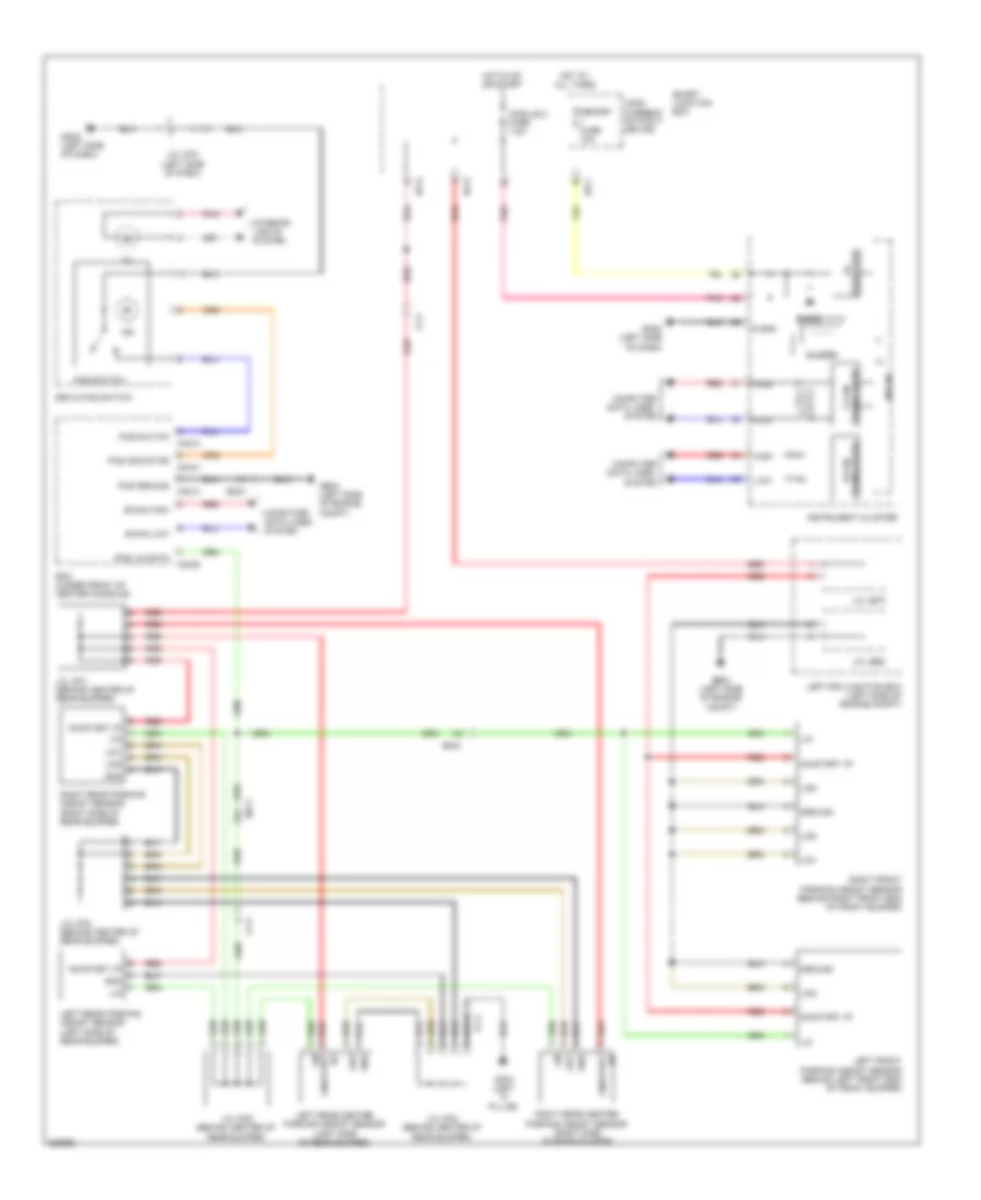 https://portal-diagnostov.com/license.html
Automotive Electricians Portal FZCO
Automotive Electricians Portal FZCO
https://portal-diagnostov.com/license.html
https://portal-diagnostov.com/license.html
Automotive Electricians Portal FZCO
Automotive Electricians Portal FZCOList of elements for Parking Assistant Wiring Diagram for Hyundai Genesis Coupe 2.0T Premium 2013:
- (+)
- (-)
- 5v regulator
- B-can high
- B-can low
- Bcm (under front of center console)
- Buzzer
- Computer
- Computer data lines system
- Data lines
- Em21
- Esc & pas switch
- Ff11
- Ge04 (left side of engine compt)
- Gf04 (left "c" pillar)
- Gm02 (left side of dash)
- Gnd
- Ground
- High
- Hot at all times
- Hot in on or start
- I/p
- I/p-c
- I/p-e
- I/p-g
- Ill
- Ind
- Instrument cluster
- Interior lights system
- J/c je68
- J/c je70
- J/c jf01 (behind center of rear bumper)
- J/c jf02 (behind center of rear bumper)
- J/c jf03 (behind center of rear bumper)
- J/c jf04 (behind center of rear bumper)
- J/c jm01 (left side of dash)
- Leak current autocut device
- Left e/r junction box (left side of engine compt)
- Left front parking assist sensor (behind left front end of front bumper)
- Left rear center parking assist sensor (left side of rear bumper)
- Left rear parking assist sensor (left side of rear bumper)
- Lid1
- Lid2
- Lid3
- Lin
- Low
- M02-a
- M02-b
- M02-c
- Memory fuse 10a
- Mf11
- Micom
- Module 2 fuse 7.5a
- On/start
- On/start i/p
- On/start lin
- Pas ground
- Pas indicator
- Pas lin data
- Pas switch
- Pnk
- Red
- Right front parking assist sensor (behind right front end of front bumper)
- Right rear center parking assist sensor (right side of rear bumper)
- Right rear parking assist sensor (right side of rear bumper)
- S gnd
- Smart junction box
- System
- Transceiver b-can
- Transceiver c-can
POWER DISTRIBUTION
Power Distribution Wiring Diagram (1 of 8) for Hyundai Genesis Coupe 2.0T Premium 2013
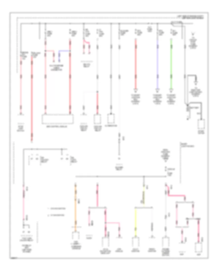 https://portal-diagnostov.com/license.html
Automotive Electricians Portal FZCO
Automotive Electricians Portal FZCO
https://portal-diagnostov.com/license.html
https://portal-diagnostov.com/license.html
Automotive Electricians Portal FZCO
Automotive Electricians Portal FZCOList of elements for Power Distribution Wiring Diagram (1 of 8) for Hyundai Genesis Coupe 2.0T Premium 2013:
- (left side of engine compt) left e/r junction box
- A/v & navigation head unit
- Abs 1 fuse 40a
- Abs 2 fuse 40a
- Alt fuse 150a
- Alternator
- Amp
- Audio
- B+1 fuse 60a
- B+2 fuse 60a
- B+3 fuse 60a
- Battery
- Blower fuse 40a
- Blower relay
- Brake sw fuse 10a
- C/ fan fuse 60a
- Check connector
- Cooling fan (hi) relay
- Cooling fan (lo) relay
- Dr lock fuse 10a
- Dr lock relay
- Dr unlock relay
- Esc control module
- F03-a
- F04-a
- Fd11
- From module 6 fuse (diagram 3 of 8)
- Front monitor
- Haco
- I/p-b
- I/p-c
- I/p-e
- I/p-g
- Icm relay box (left side of dash)
- Jbl
- Junction box (diagram 4 of 8)
- Junction box (diagram 7 of 8)
- Junction box (diagram 8 of 8)
- M03-b
- M13-a
- M70-b
- Map lamp
- Module fuse 7.5a
- Mr11
- Mts module
- Multi fuse
- Multi monitor
- Multipurpose
- Overhead console
- Pnk
- Power outside mirror switch
- Red
- Rr htd fuse 40a
- Rr htd relay
- Smart junction box
- Start motor
- Stop lamp switch
- To right e/r junction box (diagram 2 of 8)
- To smart
- To vacuum pump fuse (diagram 2 of 8)
- Two turn unlock relay
- W/ navigation
- W/o navigation
Power Distribution Wiring Diagram (2 of 8) for Hyundai Genesis Coupe 2.0T Premium 2013
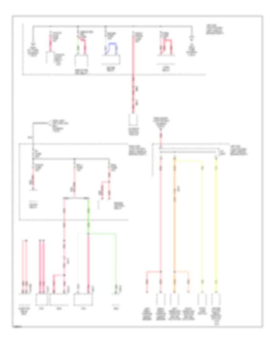 https://portal-diagnostov.com/license.html
Automotive Electricians Portal FZCO
Automotive Electricians Portal FZCO
https://portal-diagnostov.com/license.html
https://portal-diagnostov.com/license.html
Automotive Electricians Portal FZCO
Automotive Electricians Portal FZCOList of elements for Power Distribution Wiring Diagram (2 of 8) for Hyundai Genesis Coupe 2.0T Premium 2013:
- (2.0l a/t)
- (diagram 3 of 8)
- (or pnk) red
- (or red) pnk
- 2.0l
- 3.8l
- B+ fuse 50a
- Chg-k
- Chg-t
- Clg-idb
- Clg-t
- Cruise clutch pedal position switch (3.8l
- Dedicated drl fuse 10a
- Dedicated drl relay
- Deicer fuse 15a
- Deicer relay
- Ec21
- Ecm
- Ecu 1 fuse 10a
- Ee11
- Elg-a
- Em21
- Ems fuse 30a
- Engine control relay
- F/pump fuse 20a
- F/pump relay
- From b+1 fuse (diagram 1 of 8)
- From left e/r junction box (diagram 1 of 8)
- From smart junction box (diagram 5 of 8)
- Front s/roof fuse 20a
- Horn fuse 15a
- Horn relay
- Injector drive box
- J/c je70
- Left e/r junction box (left side of engine compt)
- Left front parking assist sensor
- Left headlamp leveling device actuator
- M/t)
- Mr11
- Pnk
- Red
- Right e/r junction box (right rear of engine compt)
- Right front parking assist sensor
- Right headlamp leveling device actuator
- Stop lamp switch
- Sunroof control module
- Tcm
- To ign 2 fuse
- Vacuum pump fuse 15a
- Vacuum pump relay
Power Distribution Wiring Diagram (3 of 8) for Hyundai Genesis Coupe 2.0T Premium 2013
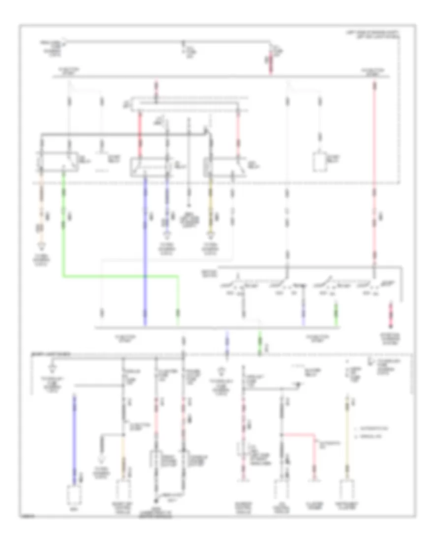 https://portal-diagnostov.com/license.html
Automotive Electricians Portal FZCO
Automotive Electricians Portal FZCO
https://portal-diagnostov.com/license.html
https://portal-diagnostov.com/license.html
Automotive Electricians Portal FZCO
Automotive Electricians Portal FZCOList of elements for Power Distribution Wiring Diagram (3 of 8) for Hyundai Genesis Coupe 2.0T Premium 2013:
- (left side of engine compt)
- (left side of engine compt) left e/r junction box
- (or red) pnk
- A/bag ind
- A/c control module
- Acc
- Acc relay
- Automatic a/c
- Bcm
- Blower relay
- C/lighter fuse 15a
- Cluster ionizer
- Console power outlet
- Em11
- Em21
- From horn g fuse (diagram 2 of 8)
- Front power outlet
- Fuse (diagram 1 of 8)
- Fuse (diagram 4 of 8)
- Fuse 7.5a
- Ge04
- Gm06 (under front of center console)
- I/p-a
- I/p-b
- I/p-c
- I/p-d
- Ig 1 fuse 40a
- Ig 2 fuse 30a
- Ig1 relay
- Ig2 relay
- Ignition
- Instrument cluster
- J/c je68
- J/c je71
- J/c jr01 (left side of front headliner)
- Lock
- M02-a
- M06-a
- M07-a
- M14-a
- Manual a/c
- Mm11
- Module 7
- Module fuse 10a
- Mr11
- Nca
- Pnk
- Power outlet fuse 15a
- Red
- Smart junction box
- Smart key control module
- Start
- Start relay
- Starting/ charging system
- Sunroof control module
- Switch
- To module 1
- To module 3 fuse (diagram 5 of 8)
- To module 4
- To pdm (diagram 6 of 8)
- W/ button start
- W/o button start
Power Distribution Wiring Diagram (4 of 8) for Hyundai Genesis Coupe 2.0T Premium 2013
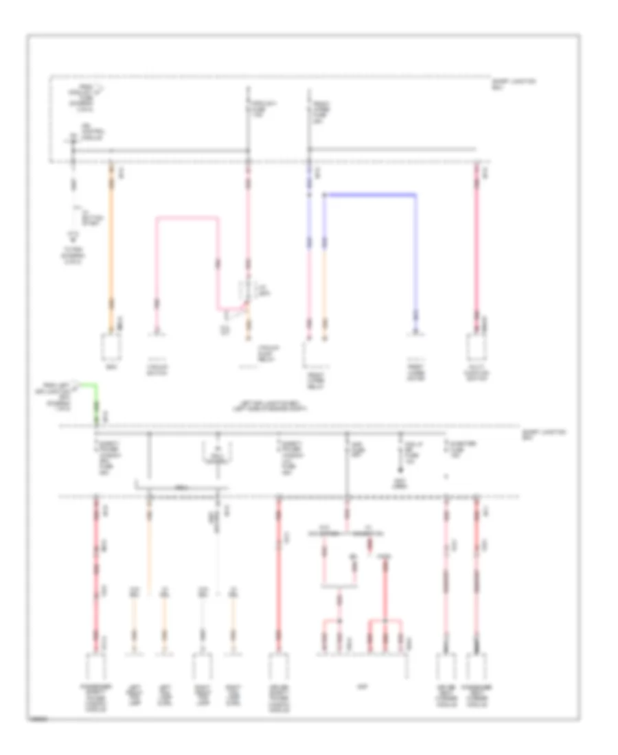 https://portal-diagnostov.com/license.html
Automotive Electricians Portal FZCO
Automotive Electricians Portal FZCO
https://portal-diagnostov.com/license.html
https://portal-diagnostov.com/license.html
Automotive Electricians Portal FZCO
Automotive Electricians Portal FZCOList of elements for Power Distribution Wiring Diagram (4 of 8) for Hyundai Genesis Coupe 2.0T Premium 2013:
- (not used)
- 2.0l a/t
- Amp
- Amp fuse 25a
- Bcm
- D17-a
- Driver safety power window module
- Driver seat warmer module
- F03-a
- F04-a
- Fd11
- Fd21
- Fog lp rr fuse 10a
- From left c e/r junction box (diagram 1 of 8)
- From module 7 m
- Front wiper fuse 25a
- Front wiper motor
- Front wiper relay
- Fs11
- Fs21
- Fuse (diagram 3 of 8)
- Fuse 7.5a
- Haco
- I/p-b
- I/p-d
- I/p-e
- I/p-f
- Ips 2
- Ips 2 control
- Ips control module
- J/c je70
- Jbl
- Left e/r junction box (left side of engine compt)
- Left fog lamp & drl
- Left front fog lamp
- M02-a
- M48-w
- Mf31
- Module 4
- Multi- function switch
- Nca
- On i/p
- Passenger safety power window module
- Passenger seat warmer module
- Pnk
- Red
- Right fog lamp & drl
- Right front fog lamp
- S/heater fuse 15a
- Safety power window (lh) fuse 25a
- Safety power window (rh) fuse 25a
- Smart junction box
- To pdm (diagram 6 of 8)
- Vacuum pump relay
- Vacuum switch
- W/ button start
- W/ drl
- W/ navigation
- W/o drl
- W/o navigation
Power Distribution Wiring Diagram (5 of 8) for Hyundai Genesis Coupe 2.0T Premium 2013
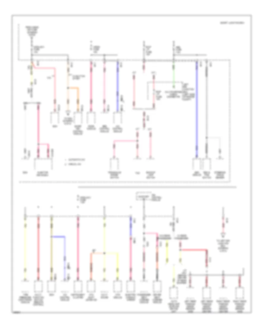 https://portal-diagnostov.com/license.html
Automotive Electricians Portal FZCO
Automotive Electricians Portal FZCO
https://portal-diagnostov.com/license.html
https://portal-diagnostov.com/license.html
Automotive Electricians Portal FZCO
Automotive Electricians Portal FZCOList of elements for Power Distribution Wiring Diagram (5 of 8) for Hyundai Genesis Coupe 2.0T Premium 2013:
- 2.0l
- 3.8l
- A/bag fuse 15a
- A/c control module
- A/t
- Abs fuse 7.5a
- Atm shift lever ind
- Auto headlamp leveling device unit
- Automatic a/c
- B/up l/p fuse 10a
- B/up l/p fuse 15a
- Backup lamp switch
- Bcm
- Chg-k
- Clg-idb
- Driver seat warmer module
- Ec21
- Ecm
- Electro- chromic mirror
- Elg-a
- Esc & pas switch
- Esc module
- Ff11
- From a/bag ind fuse (diagram 3 of 8)
- Fs11
- Fs21
- I/p-a
- I/p-c
- I/p-e
- I/p-f
- I/p-g
- Injector drive box
- Instrument cluster
- Ips control module
- J/c jf01 (behind center of rear bumper)
- Junction box (diagram 2 of 8)
- Left e/r junction box (left side of engine compt)
- Left rear parking assist sensor center
- Left rear parking assist sensor side
- M/t
- M02-a
- M06-a
- M06-b
- M07-a
- M07-b
- M14-a
- M71-a
- Manual a/c
- Module 2 fuse 7.5a
- Module 3 fuse 10a
- Mr11
- Mts module
- Multi gauge
- Multi- function switch (remote control)
- Multipurpose check connector
- Nca
- On/start i/p
- Passenger seat warmer module
- Pnk
- Pods module
- Red
- Right rear parking assist sensor center
- Right rear parking assist sensor side
- Smart junction box
- Smart key control module
- Srs control module
- Steering angle sensor
- Tcm
- Tire pressure monitoring module
- To left e/r
- To pdm (diagram 6 of 8)
- Transaxle range switch
- W/ button start
- W/ rear passenger
- W/o rear passenger
Power Distribution Wiring Diagram (6 of 8) for Hyundai Genesis Coupe 2.0T Premium 2013
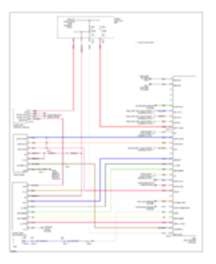 https://portal-diagnostov.com/license.html
Automotive Electricians Portal FZCO
Automotive Electricians Portal FZCO
https://portal-diagnostov.com/license.html
https://portal-diagnostov.com/license.html
Automotive Electricians Portal FZCO
Automotive Electricians Portal FZCOList of elements for Power Distribution Wiring Diagram (6 of 8) for Hyundai Genesis Coupe 2.0T Premium 2013:
- (left side of dash) gm02
- 10a
- 2.0l
- 25a
- 3.8l
- Acc
- Acc rly
- Anti-lock brakes system
- B-can high
- B-can low
- Batt-cpu
- Batt-laod
- Chg-k
- Computer data lines system
- Ec11
- Ecm
- Elg-a
- Em51
- F-rpm
- F-wheel spd
- Fob holder
- Fob in
- From left e/r junction box h (diagram 3 of 8)
- From left e/r junction box j (diagram 3 of 8)
- From left e/r junction box k (diagram 3 of 8)
- From module 5 s
- From smart junction box l (diagram 3 of 8)
- From smart p junction box (diagram 4 of 8)
- From smart q junction box (diagram 5 of 8)
- Fuse (diagram 7 of 8)
- Gm01 (left end of dash)
- Gm06 (under front of center console)
- Gnd
- Ground
- Holder ill
- I/p-b
- I/p-d
- Ig1
- Ig2
- Ign 1 rly
- Ign 2 rly
- Ill gnd
- Ill pwr
- Ill(+)
- Ill(-)
- Immo clock
- Immo data
- Interior lights system
- Key in sw
- Led amber
- Led green
- M14-a
- M51-a
- M51-b
- Mm11
- Pdm (left center of dash)
- Pdm fuse
- Pnk
- Red
- Smart junction box
- Smart key control module
- Ssb amber
- Ssb green
- Ssb ill pwr
- Ssb sw1
- Ssb sw2
- Start feed back
- Start rly
- Start stop button switch
- Starting/charging system
- Sw1
- Sw2
- W/ button start
Power Distribution Wiring Diagram (7 of 8) for Hyundai Genesis Coupe 2.0T Premium 2013
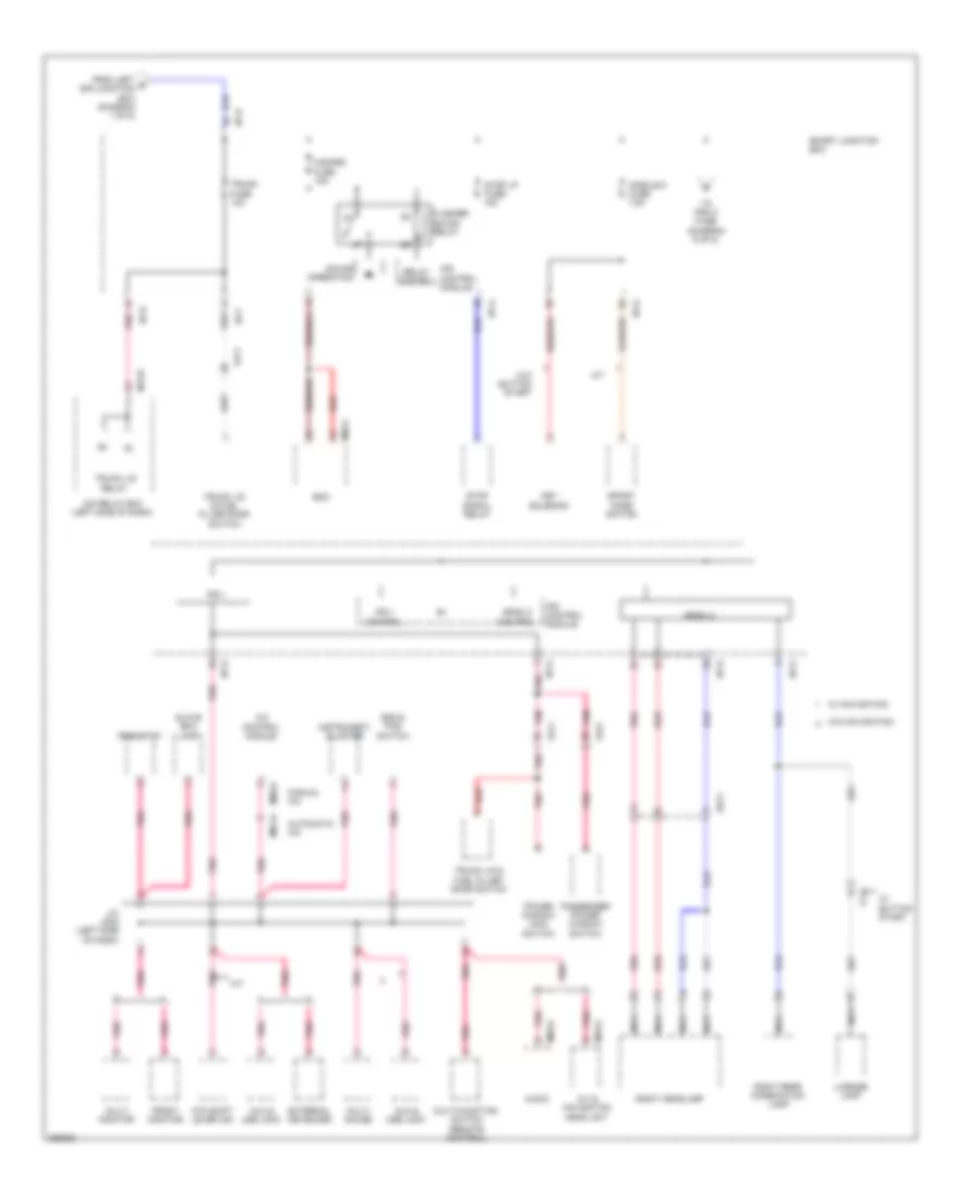 https://portal-diagnostov.com/license.html
Automotive Electricians Portal FZCO
Automotive Electricians Portal FZCO
https://portal-diagnostov.com/license.html
https://portal-diagnostov.com/license.html
Automotive Electricians Portal FZCO
Automotive Electricians Portal FZCOList of elements for Power Distribution Wiring Diagram (7 of 8) for Hyundai Genesis Coupe 2.0T Premium 2013:
- A/c control module
- A/t
- A/v & navigation head unit
- Arisu 2
- Arisu 2 control
- Atm shift lever ind
- Audio
- Automatic a/c
- Aux & usb jack
- Bcm
- Ee11
- Esc & pas switch
- External keyboard
- Fd11
- Fd21
- Ff11
- Flasher sound relay
- From left b e/r junction box (diagram 1 of 8)
- Front monitor
- Glove box lamp
- Hazard fuse 15a
- I/p-a
- I/p-b
- I/p-d
- I/p-e
- I/p-f
- I/p-g
- Icm relay box (left side of dash)
- Instrument cluster
- Ips 1
- Ips 1 control
- Ips control module
- J/c jm02 (left side of dash)
- Key solenoid
- License lamp
- M02-c
- M03-a
- M06-a
- M07-a
- M13-b
- M70-a
- Manual a/c
- Module 5 fuse 7.5a
- Multi gauge
- Multi monitor
- Multi-function switch (remote control)
- Nca
- Passenger power window switch
- Pnk
- Power window main switch
- Red
- Relay control
- Rheostat
- Right headlamp
- Right rear combination lamp
- Smart junction box
- Sound operation
- Sport mode switch
- Stop lp fuse 15a
- Stop signal relay
- To pdm 2 fuse (diagram 6 of 8)
- Trunk fuse 10a
- Trunk lid & fuel filler door switch
- Trunk lid relay
- W/ button start
- W/ navigation
- W/o button start
- W/o navigation
Power Distribution Wiring Diagram (8 of 8) for Hyundai Genesis Coupe 2.0T Premium 2013
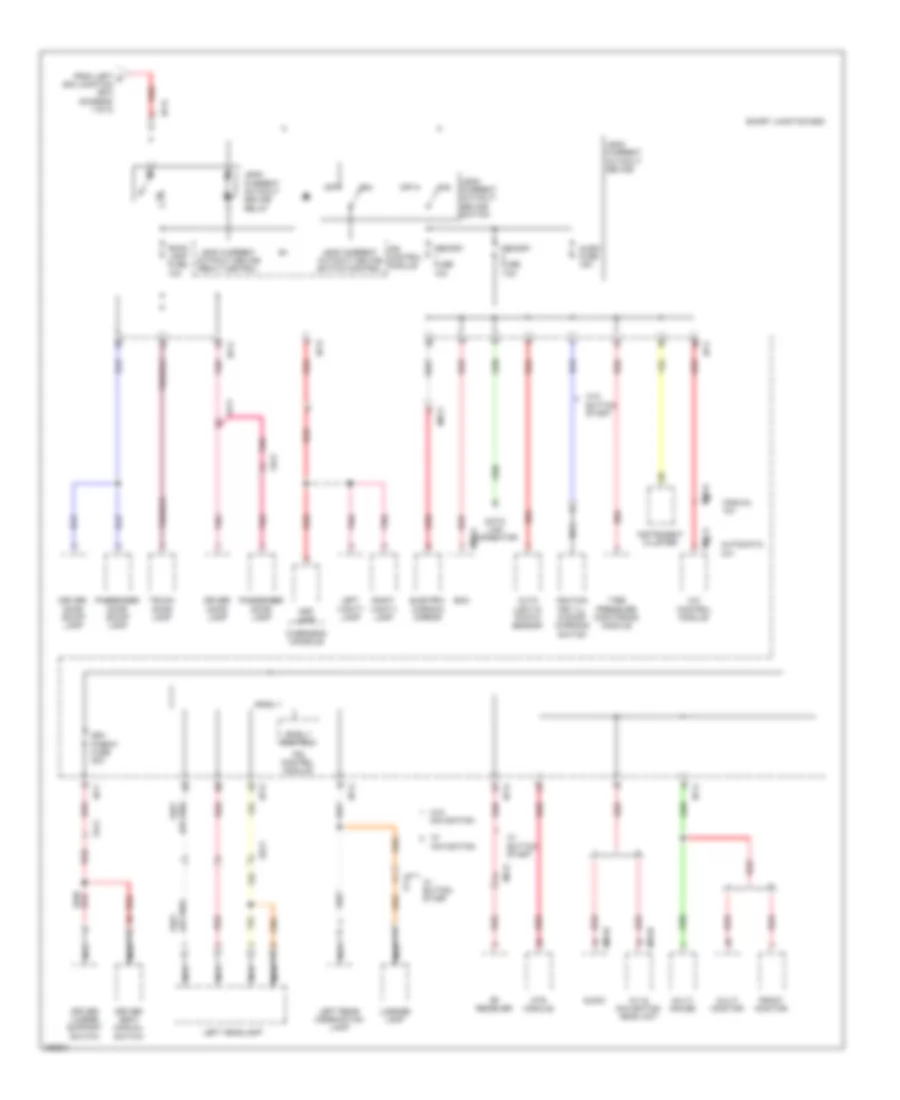 https://portal-diagnostov.com/license.html
Automotive Electricians Portal FZCO
Automotive Electricians Portal FZCO
https://portal-diagnostov.com/license.html
https://portal-diagnostov.com/license.html
Automotive Electricians Portal FZCO
Automotive Electricians Portal FZCOList of elements for Power Distribution Wiring Diagram (8 of 8) for Hyundai Genesis Coupe 2.0T Premium 2013:
- A/c control module
- A/v & navigation head unit
- Arisu 1
- Arisu 1 control
- Audio
- Audio fuse 15a
- Auto light & photo sensor
- Automatic a/c
- Bcm
- Data link connector
- Driver door lamp
- Driver door scuff lamp
- Driver lumbar support switch
- Driver seat manual switch
- Drv p/seat fuse 30a
- Ee11
- Electro- chromic mirror
- Fd11
- Fd21
- Ff11
- From left d e/r junction box (diagram 1 of 8)
- Front monitor
- Fs11
- I/p-a
- I/p-c
- I/p-d
- I/p-e
- I/p-f
- I/p-g
- Ignition key ill & door warning switch
- Instrument cluster
- Ips control module
- Leak current autocut device
- Leak current autocut device realy control
- Leak current autocut device relay
- Leak current autocut device switch
- Leak current autocut device switch control
- Left headlamp
- Left rear combination lamp
- Left vanity lamp
- License lamp
- M02-a
- M03-b
- M06-a
- M07-a
- M70-b
- Manual a/c
- Map lamp
- Memory fuse 10a
- Memory fuse 7.5a
- Mf31
- Mr11
- Mts module
- Multi gauge
- Multi monitor
- Navigation
- Nca
- Off
- Overhead console
- Passenger door lamp
- Passenger door scuff lamp
- Pnk
- Red
- Rf receiver
- Right vanity lamp
- Room lamp fuse 10a
- Smart junction box
- Tire pressure monitoring module
- Trunk door lamp
- W/ button start
- W/o button start
- W/o navigation
POWER DOOR LOCKS
Power Door Locks Wiring Diagram (1 of 2) for Hyundai Genesis Coupe 2.0T Premium 2013
 https://portal-diagnostov.com/license.html
Automotive Electricians Portal FZCO
Automotive Electricians Portal FZCO
https://portal-diagnostov.com/license.html
https://portal-diagnostov.com/license.html
Automotive Electricians Portal FZCO
Automotive Electricians Portal FZCOList of elements for Power Door Locks Wiring Diagram (1 of 2) for Hyundai Genesis Coupe 2.0T Premium 2013:
- (left side of engine compt) ge04
- 87a
- Arisu 1 ctrl
- Arisu 2 ctrl
- B-can
- B-can hi
- B-can lo
- Bcm (under front of center console)
- Box
- Computer data lines system
- Door lock relay
- Door lock relay ctrl
- Door lock sw
- Door unlock relay
- Door unlock relay ctrl
- Door unlock sw
- Dr lk
- Dr lock fuse 10a
- Dr unlk
- Driver door lock actuator (driver door)
- Driver door sw
- Fd11
- Fd21
- Gf01 (left kick panel)
- Gf05 (right kick panel)
- Gm01 (left end of dash)
- Headlights system
- High
- Hood sw
- Hood switch (left side of engine compt)
- Horn relay ctrl
- Hot at all times
- Hot in on
- I/p-b
- I/p-c
- I/p-d
- I/p-e
- I/p-f
- I/p-g
- Ips control module
- Key lk
- Key lock
- Key unlk
- Key unlock
- Leak current auto cut device
- Left e/r junction box (left side of engine compt)
- Lock/ unlock
- Low
- M02-b
- Memory 1 fuse 10a
- Module 4 fuse 7.5a
- Nca
- On input
- Passenger door lock actuator (passenger door)
- Passenger door lock/ unlock sw
- Red
- Security ind m02-c
- Smart junction
- Two turn unlock relay ctrl
Power Door Locks Wiring Diagram (2 of 2) for Hyundai Genesis Coupe 2.0T Premium 2013
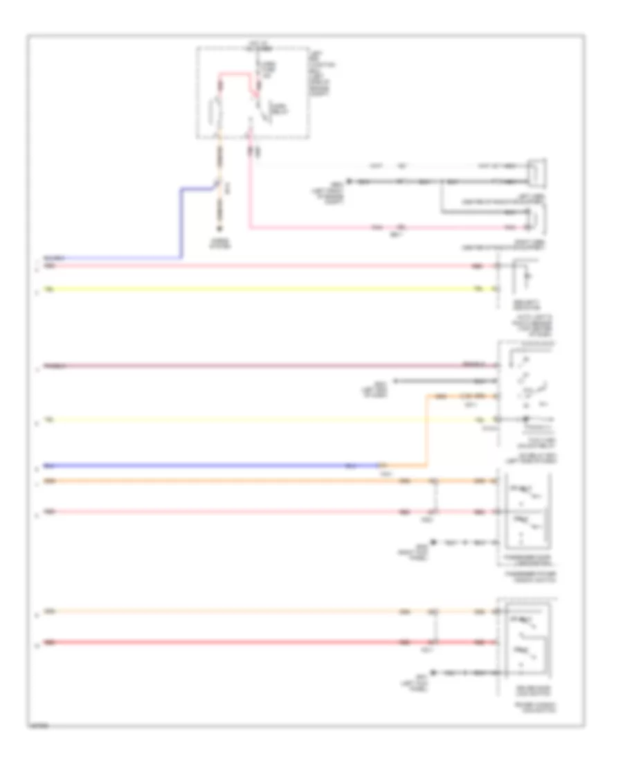 https://portal-diagnostov.com/license.html
Automotive Electricians Portal FZCO
Automotive Electricians Portal FZCO
https://portal-diagnostov.com/license.html
https://portal-diagnostov.com/license.html
Automotive Electricians Portal FZCO
Automotive Electricians Portal FZCOList of elements for Power Door Locks Wiring Diagram (2 of 2) for Hyundai Genesis Coupe 2.0T Premium 2013:
- 87a
- Auto light & photo sensor (top center of dash)
- Dr lk
- Dr unlk
- Driver door lock switch
- Ee11
- Fd11
- Fd21
- Ge03 (left front of engine compt)
- Gf01 (left kick panel)
- Gf05 (right kick panel)
- Gm01 (left end of dash)
- Horn fuse 15a
- Horn relay
- Horns system
- Hot at all times
- I/p-d
- Icm relay box (left side of dash)
- Left e/r junction box (left side of engine compt)
- Left horn (center of radiator support)
- M13-a
- Mf11
- Nca
- Passenger door lock switch
- Passenger power window switch
- Pnk
- Power window main switch
- Red
- Right horn (center of radiator support)
- Security indicator
- Two turn unlock relay
POWER MIRRORS
Electrochromic Mirror Wiring Diagram, with Home Link for Hyundai Genesis Coupe 2.0T Premium 2013
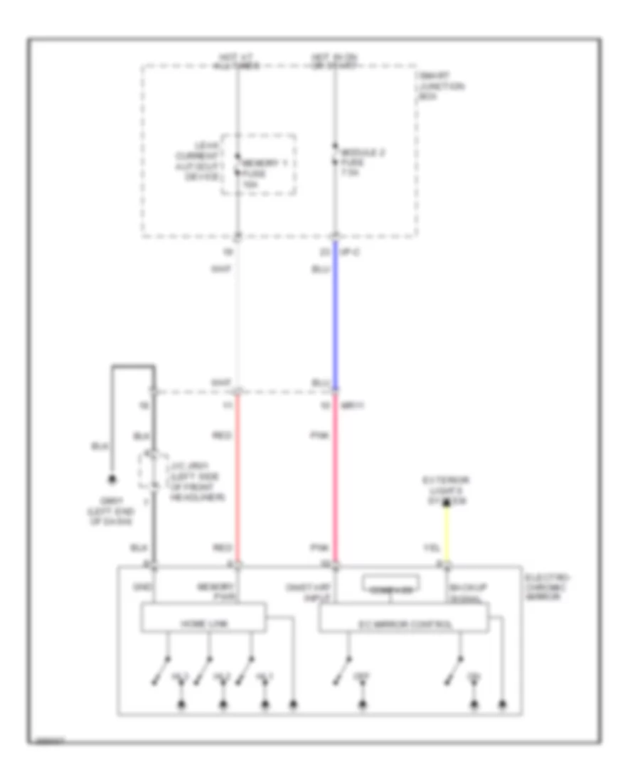 https://portal-diagnostov.com/license.html
Automotive Electricians Portal FZCO
Automotive Electricians Portal FZCO
https://portal-diagnostov.com/license.html
https://portal-diagnostov.com/license.html
Automotive Electricians Portal FZCO
Automotive Electricians Portal FZCOList of elements for Electrochromic Mirror Wiring Diagram, with Home Link for Hyundai Genesis Coupe 2.0T Premium 2013:
- Backup signal
- Compass
- Ec mirror control
- Electro- chromic mirror
- Exterior lights system
- Gm01 (left end of dash)
- Gnd
- Hl1
- Hl2
- Hl3
- Home link
- Hot at all times
- Hot in on or start
- I/p-c
- J/c jr01 (left side of front headliner)
- Leak current autocut device
- Memory 1 fuse 10a
- Memory pwr
- Module 2 fuse 7.5a
- Mr11
- Off
- On/start input
- Pnk
- Red
- Smart junction box
Electrochromic Mirror Wiring Diagram, with TMU & Home Link for Hyundai Genesis Coupe 2.0T Premium 2013
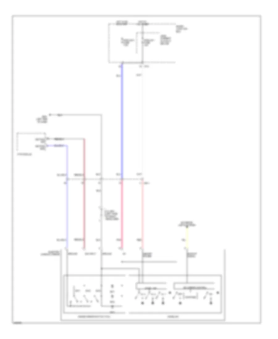 https://portal-diagnostov.com/license.html
Automotive Electricians Portal FZCO
Automotive Electricians Portal FZCO
https://portal-diagnostov.com/license.html
https://portal-diagnostov.com/license.html
Automotive Electricians Portal FZCO
Automotive Electricians Portal FZCOList of elements for Electrochromic Mirror Wiring Diagram, with TMU & Home Link for Hyundai Genesis Coupe 2.0T Premium 2013:
- Backup signal
- Compass
- Ec mirror control
- Electro- chromic mirror
- Exterior lights system
- Gm01 (left end of dash)
- Ground
- Hl 1
- Hl 2
- Hl 3
- Home link
- Homelink
- Hot at all times
- Hot in on or start
- I/p-c
- Ig1
- Inside mirror switch (tmu)
- J/c jr01 (left side of front headliner)
- Keypad gnd
- Keypad sig
- Leak current autocut device
- Memory power
- Module 1 fuse 10a
- Module 2 fuse 7.5a
- Mr11
- Mts module
- Off
- Pnk
- Red
- Sig input
- Smart junction box
- Sw1
- Sw2
- Sw3
Electrochromic Mirror Wiring Diagram, with TMU for Hyundai Genesis Coupe 2.0T Premium 2013
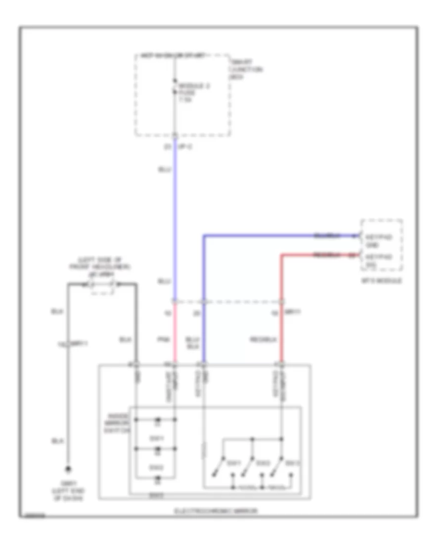 https://portal-diagnostov.com/license.html
Automotive Electricians Portal FZCO
Automotive Electricians Portal FZCO
https://portal-diagnostov.com/license.html
https://portal-diagnostov.com/license.html
Automotive Electricians Portal FZCO
Automotive Electricians Portal FZCOList of elements for Electrochromic Mirror Wiring Diagram, with TMU for Hyundai Genesis Coupe 2.0T Premium 2013:
- (left side of front headliner) j/c jr01
- Electrochromic mirror
- Gm01 (left end of dash)
- Gnd
- Gnd keypad
- Hot in on or start
- I/p-c
- Inside mirror switch
- Keypad
- Module 2 fuse 7.5a
- Mr11
- Mts module
- On/start input
- Pnk
- Sig
- Sig input keypad
- Smart junction box
- Sw1
- Sw2
- Sw3
Power Mirrors Wiring Diagram for Hyundai Genesis Coupe 2.0T Premium 2013
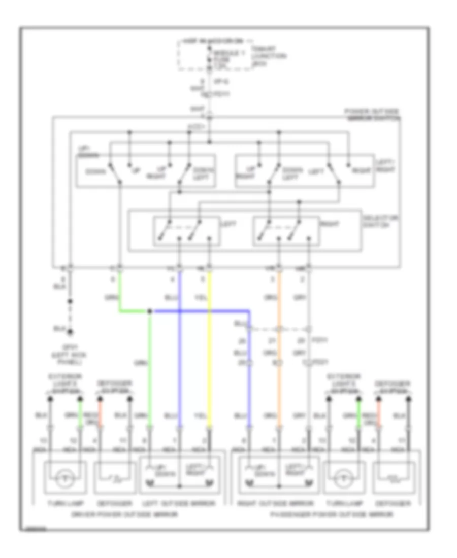 https://portal-diagnostov.com/license.html
Automotive Electricians Portal FZCO
Automotive Electricians Portal FZCO
https://portal-diagnostov.com/license.html
https://portal-diagnostov.com/license.html
Automotive Electricians Portal FZCO
Automotive Electricians Portal FZCOList of elements for Power Mirrors Wiring Diagram for Hyundai Genesis Coupe 2.0T Premium 2013:
- Acc+
- Defogger
- Defogger system
- Down
- Down left
- Driver power outside mirror
- Exterior lights system
- Fd11
- Fd21
- Gf01 (left kick panel)
- Hot in acc or on
- I/p-g
- Left
- Left outside mirror
- Left/ right
- Module 1 fuse 7.5a
- Nca
- Passenger power outside mirror
- Power outside mirror switch
- Right
- Right outside mirror
- Selector switch
- Smart junction box
- Turn lamp
- Up right
- Up/ down
POWER SEATS
Heated Seats Wiring Diagram for Hyundai Genesis Coupe 2.0T Premium 2013
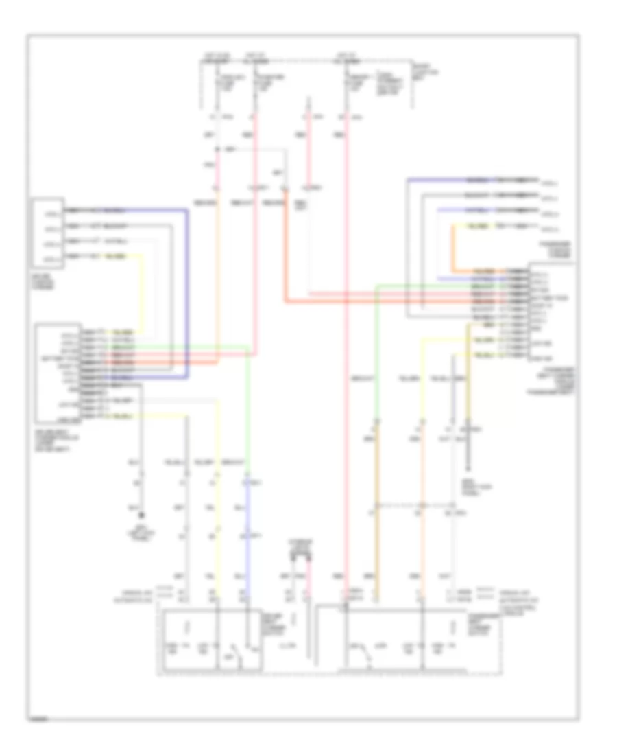 https://portal-diagnostov.com/license.html
Automotive Electricians Portal FZCO
Automotive Electricians Portal FZCO
https://portal-diagnostov.com/license.html
https://portal-diagnostov.com/license.html
Automotive Electricians Portal FZCO
Automotive Electricians Portal FZCOList of elements for Heated Seats Wiring Diagram for Hyundai Genesis Coupe 2.0T Premium 2013:
- A/c control module
- Automatic a/c
- Battery pwr
- Driver cushion warmer
- Driver seat warmer module (under driver seat)
- Driver seat warmer switch
- Fs11
- Fs21
- Gf01 (left kick panel)
- Gf05 (right kick panel)
- Gnd
- High ind
- Hot at all times
- Hot in on or start
- Htd (+)
- Htd (-)
- I/p-c
- I/p-f
- I/p-g
- Ill
- Interior lights system
- Leak current autocut device
- Low ind
- M06-a
- M06-b
- M07-a
- M07-b
- Manual a/c
- Memory 1 fuse 10a
- Mf11
- Mf31
- Module 2 fuse 7.5a
- Nca
- Nca battery pwr
- Nca gnd
- Nca high ind
- Nca htd (+)
- Nca htd (-)
- Nca low ind
- Nca ntc (+)
- Nca ntc (-)
- Nca on/st in
- Nca sw sig
- Ntc (+)
- Ntc (-)
- Off
- On/st in
- Passenger cushion warmer
- Passenger seat warmer module (under passenger seat)
- Passenger seat warmer switch
- Pnk
- Red
- S/heater fuse 15a
- Smart junction box
- Sw sig
Power Seats Wiring Diagram for Hyundai Genesis Coupe 2.0T Premium 2013
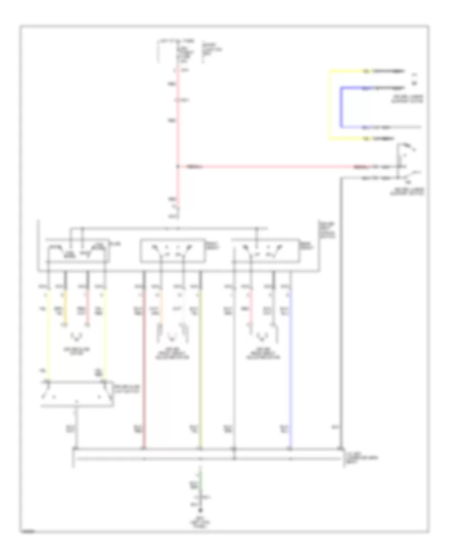 https://portal-diagnostov.com/license.html
Automotive Electricians Portal FZCO
Automotive Electricians Portal FZCO
https://portal-diagnostov.com/license.html
https://portal-diagnostov.com/license.html
Automotive Electricians Portal FZCO
Automotive Electricians Portal FZCOList of elements for Power Seats Wiring Diagram for Hyundai Genesis Coupe 2.0T Premium 2013:
- Back
- Driver front height adjuster motor
- Driver lumbar support motor
- Driver lumbar support switch
- Driver rear height adjuster motor
- Driver seat manual switch
- Driver slide limit switch
- Driver slide motor
- Drv p/seat fuse 30a
- For- ward
- Front height
- Fs11
- Gf01 (left kick panel)
- Hot at all times
- I/p-f
- J/c js01 (under driver's seat)
- Nca
- Rear height
- Red
- Slide
- Smart junction box
POWER TOP/SUNROOF
Power Top/Sunroof Wiring Diagram for Hyundai Genesis Coupe 2.0T Premium 2013
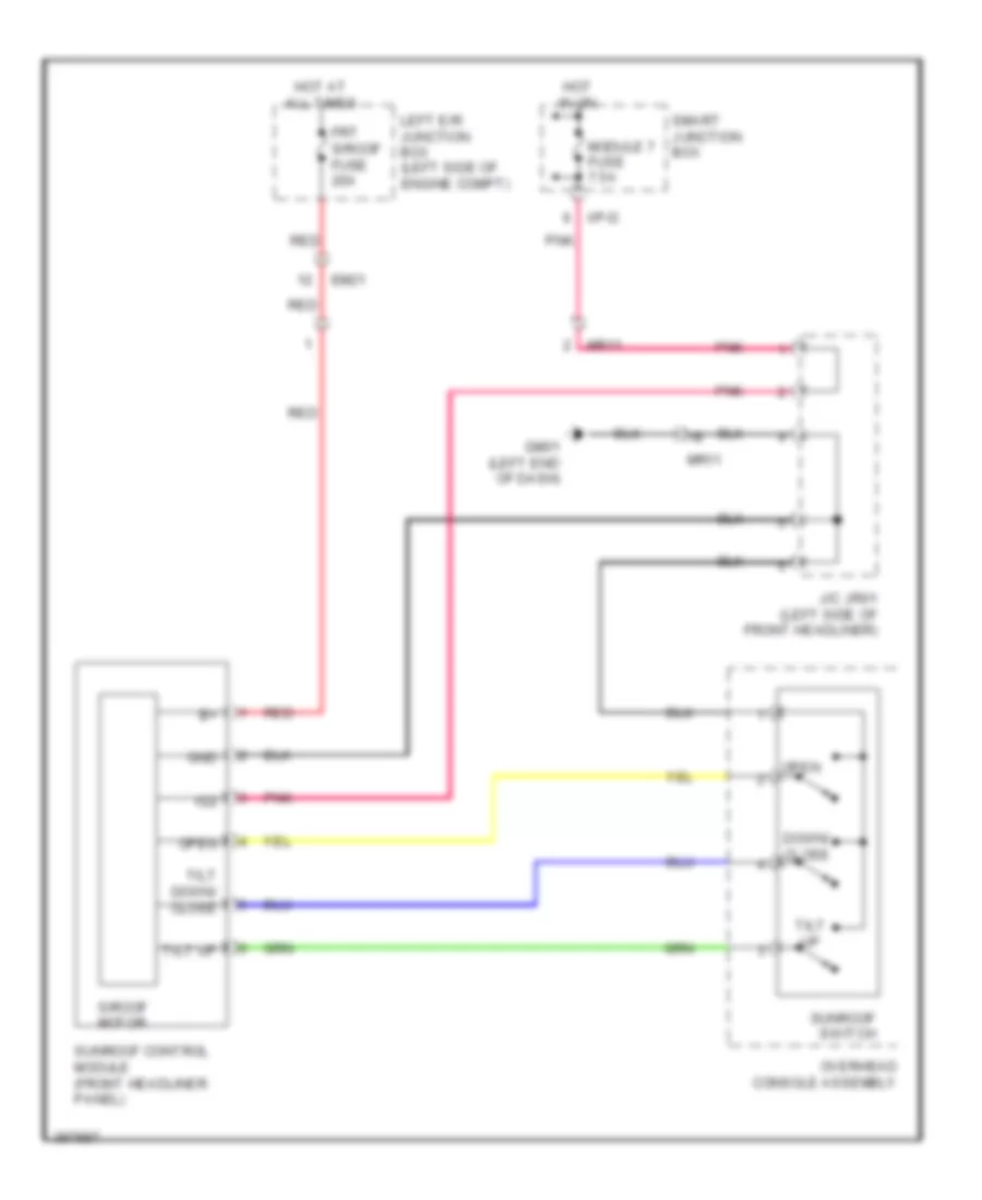 https://portal-diagnostov.com/license.html
Automotive Electricians Portal FZCO
Automotive Electricians Portal FZCO
https://portal-diagnostov.com/license.html
https://portal-diagnostov.com/license.html
Automotive Electricians Portal FZCO
Automotive Electricians Portal FZCOList of elements for Power Top/Sunroof Wiring Diagram for Hyundai Genesis Coupe 2.0T Premium 2013:
- Down/ close
- Em21
- Frt s/roof fuse 20a
- Gm01 (left end of dash)
- Gnd
- Hot at all times
- Hot in on
- I/p-d
- Ig2
- J/c jr01 (left side of front headliner)
- Left e/r junction box (left side of engine compt)
- Module 7 fuse 7.5a
- Mr11
- Open
- Overhead console assembly
- Pnk
- Red
- S/roof motor
- Smart junction box
- Sunroof control module (front headliner panel)
- Sunroof switch
- Tilt down/ close
- Tilt up
POWER WINDOWS
Power Windows Wiring Diagram for Hyundai Genesis Coupe 2.0T Premium 2013
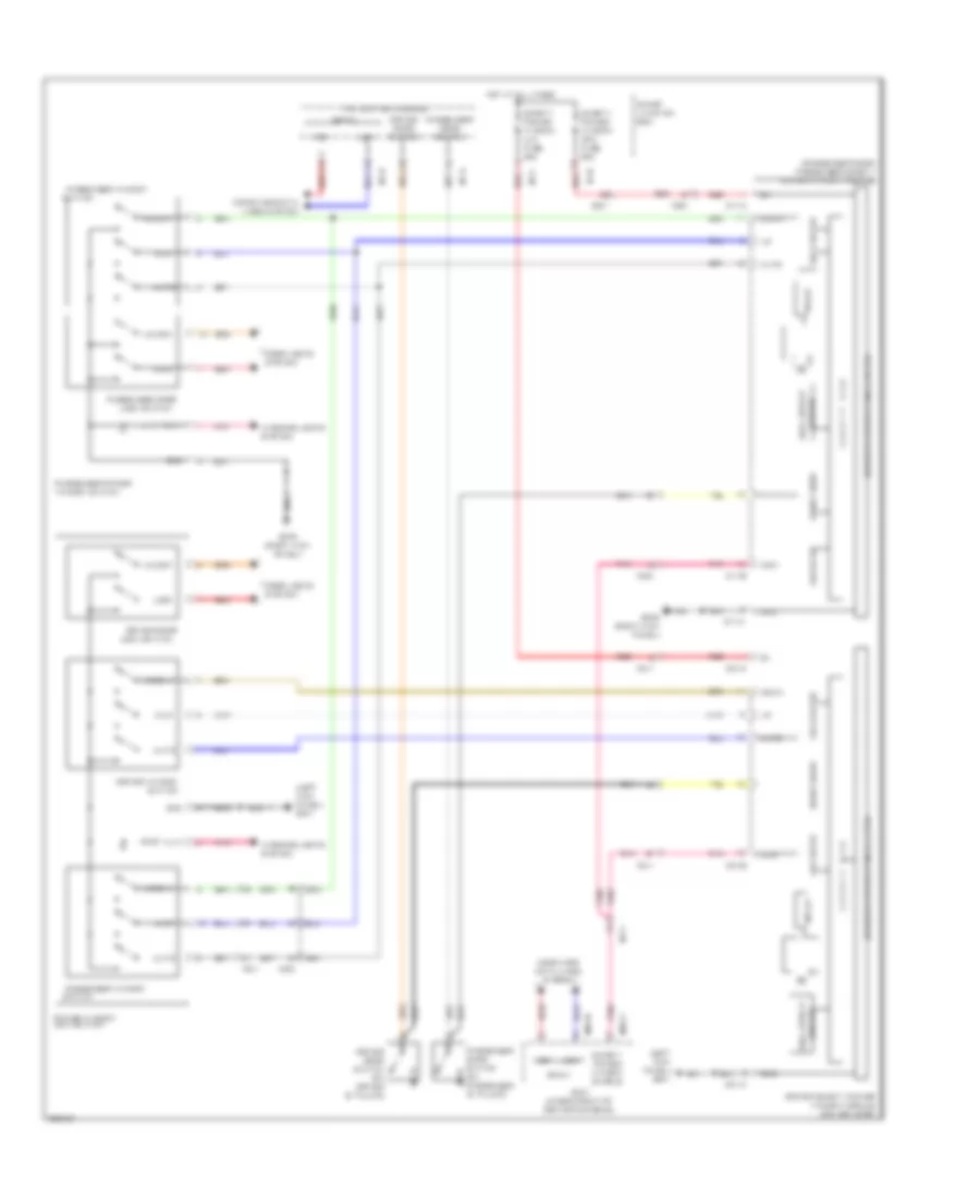 https://portal-diagnostov.com/license.html
Automotive Electricians Portal FZCO
Automotive Electricians Portal FZCO
https://portal-diagnostov.com/license.html
https://portal-diagnostov.com/license.html
Automotive Electricians Portal FZCO
Automotive Electricians Portal FZCOList of elements for Power Windows Wiring Diagram for Hyundai Genesis Coupe 2.0T Premium 2013:
- (left kick panel) gf01
- (passenger door) passenger safety power window module
- Auto
- B-can
- Bcm (under front of center console)
- Com
- Computer data lines system
- D07-a
- D07-b
- D17-a
- D17-b
- Door locks system
- Down
- Driver door
- Driver door switch
- Driver door switch (on driver "b" pillar)
- Driver safety power window module (driver door)
- Driver window switch
- Fd11
- Fd21
- Gf05 (right kick panel)
- Gnd
- Hall effect
- High
- Hot at all times
- I/p-b
- I/p-d
- I/p-f
- I/p-g
- Ill(+)
- Interior lights system
- Ips control module
- Lock
- Lock switch
- Low
- M/down
- M/up
- M02-b
- M02-c
- Mf11
- Mf31
- Passenger door
- Passenger door switch
- Passenger door switch (on passenger "b" pillar)
- Passenger power
- Passenger window
- Pnk
- Power window main switch
- Red
- Relay
- Reverse protection & filter
- S a f e t y e c u
- Safety power window (lh) fuse 25a
- Safety power window (rh) fuse 25a
- Safety power window enable
- Sensor
- Short drop
- Sig & filter
- Sig filter
- Smart junction box
- Switch
- Unlock
- Window switch
RADIO
Radio Wiring Diagram, with Navigation & with JBL Amplifier (1 of 3) for Hyundai Genesis Coupe 2.0T Premium 2013
 https://portal-diagnostov.com/license.html
Automotive Electricians Portal FZCO
Automotive Electricians Portal FZCO
https://portal-diagnostov.com/license.html
https://portal-diagnostov.com/license.html
Automotive Electricians Portal FZCO
Automotive Electricians Portal FZCOList of elements for Radio Wiring Diagram, with Navigation & with JBL Amplifier (1 of 3) for Hyundai Genesis Coupe 2.0T Premium 2013:
- (+)
- (-)
- A/v & navigation head unit
- Acc/on i/p
- Alt l
- Antenna
- Anti-lock brakes system
- Audio (+)
- Audio (-)
- Audio (-) call end of
- Audio (-) vol up
- Audio fuse 15a
- Auto light state
- Aux detect
- Aux gnd
- Aux l in
- Aux r in
- B/t (in)
- B/t (out)
- Bcm (under front of center console)
- Call
- Circuit
- Clock spring
- Computer data lines system
- Cruise control system
- Down seek
- Dr unlk state
- Exterior lights system
- Feeder cable
- Glass antenna
- Gm05 (under center of dash)
- Gnd
- Hot at all times
- I/p-a
- Ill
- Ill (+)
- Ill (-)
- Interior lights system
- Ipod vod sig
- Leak current autocut device
- Left audio remote control switch
- Left voice & mute remote control switch
- M-can high
- M-can low
- M02-c
- M48-r
- M70-a
- M70-b
- Mem power
- Mf31
- Mic (+)
- Mic (-)
- Mode
- Multi-function switch (remote control)
- Mute
- Mute (in)
- Navi voice (+)
- Navi voice (-)
- Nca
- Parking
- Pnk
- Red
- Reverse sig
- Right audio remote control switch
- Sig
- Smart junction box
- Spdif gnd
- Spdif out (+)
- Spdif out (-)
- Starting/charging system
- Steering wheel
- Up seek
- V gnd
- Veh spd sig
- Voice
- Voice (in)
- Voice (out)
- Vol (in)
- Vol (out)
- Vol dw
Radio Wiring Diagram, with Navigation & with JBL Amplifier (2 of 3) for Hyundai Genesis Coupe 2.0T Premium 2013
 https://portal-diagnostov.com/license.html
Automotive Electricians Portal FZCO
Automotive Electricians Portal FZCO
https://portal-diagnostov.com/license.html
https://portal-diagnostov.com/license.html
Automotive Electricians Portal FZCO
Automotive Electricians Portal FZCOList of elements for Radio Wiring Diagram, with Navigation & with JBL Amplifier (2 of 3) for Hyundai Genesis Coupe 2.0T Premium 2013:
- (under center of dash) gm05
- A/v & navigation head unit
- Acc/on i/p
- Audio o/p (+)
- Audio o/p (-)
- Aux & usb jack
- Aux det
- Aux gnd
- Aux l in
- Aux r in
- Bcm rx
- Bl on
- Front monitor
- Gm05
- Gm05 (under center of dash)
- Gnd
- Handsfree mic (left front of roof)
- Ill (+)
- Ill(+)
- Ill(-)
- Interior lights system
- Lvds lock
- Lvds pdn
- M70-c
- Mem pwr
- Mic (+)
- Mic (-)
- Mic out (+)
- Mic out (-)
- Mic shld
- Mts module
- Nca
- Pnk
- Red
- Rx (+)
- Rx (-)
- Tx (+)
- Tx (-)
- Usb d (+)
- Usb d (-)
- Usb gnd
- Usb high cable
- Usb vcc
- V gnd
- Vod out
- W/ mts
- W/o mts
Radio Wiring Diagram, with Navigation & with JBL Amplifier (3 of 3) for Hyundai Genesis Coupe 2.0T Premium 2013
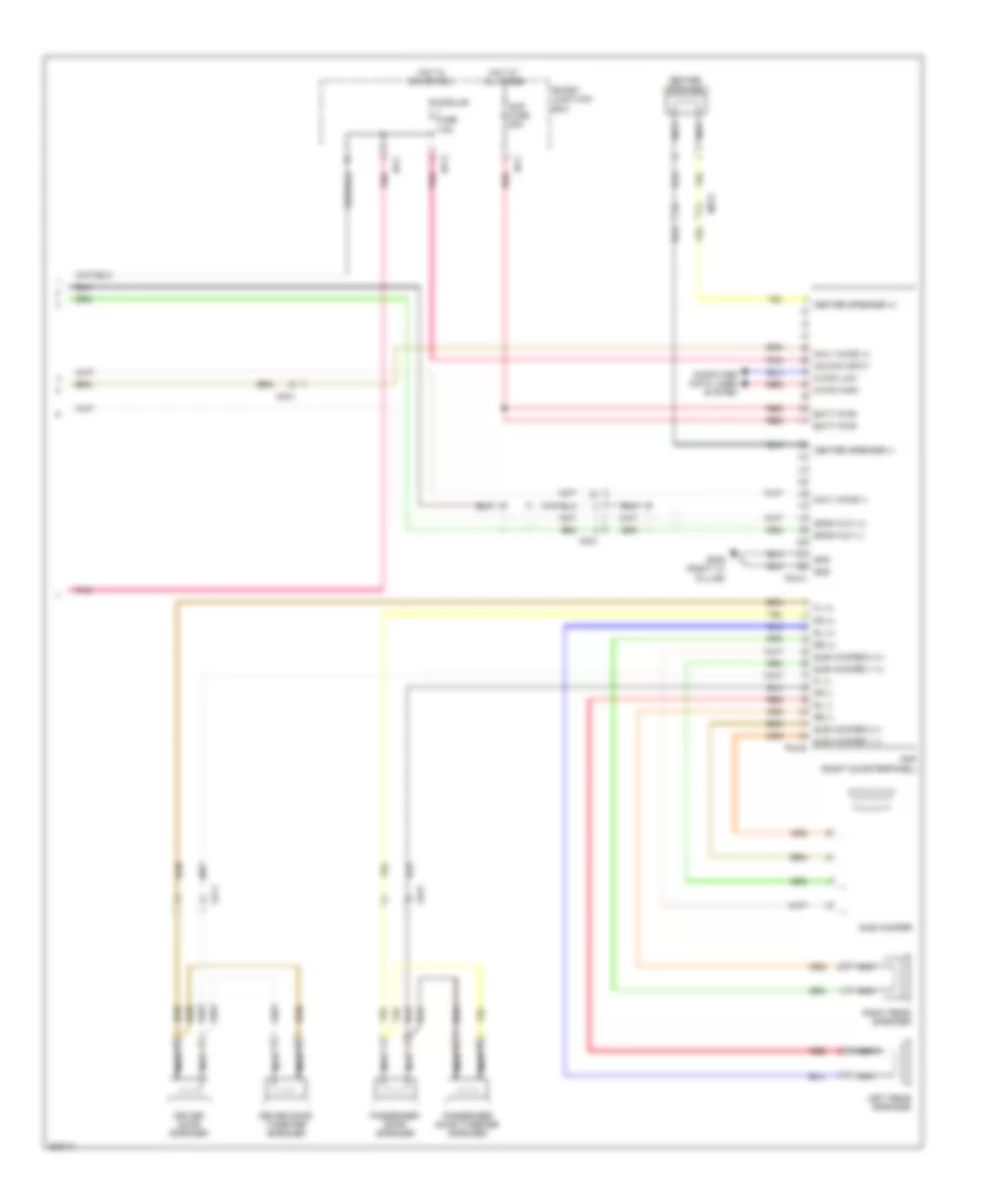 https://portal-diagnostov.com/license.html
Automotive Electricians Portal FZCO
Automotive Electricians Portal FZCO
https://portal-diagnostov.com/license.html
https://portal-diagnostov.com/license.html
Automotive Electricians Portal FZCO
Automotive Electricians Portal FZCOList of elements for Radio Wiring Diagram, with Navigation & with JBL Amplifier (3 of 3) for Hyundai Genesis Coupe 2.0T Premium 2013:
- Acc/on input
- Amp (right quarterpanel)
- Amp fuse 25a
- Batt pwr
- Center speaker
- Center speaker (+)
- Center speaker (-)
- Computer data lines system
- Driver door speaker
- Driver door tweeter speaker
- F04-a
- F04-b
- Fd11
- Fd21
- Fl (+)
- Fl (-)
- Fr (+)
- Fr (-)
- Gf08 (right "c" pillar)
- Gnd
- Hot at all times
- Hot in on or acc
- I/p-c
- I/p-f
- I/p-g
- Left rear speaker
- M-can high
- M-can low
- Mf31
- Module fuse 7.5a
- Navi voice (+)
- Navi voice (-)
- Nca
- Passenger door speaker
- Passenger door tweeter speaker
- Pnk
- Red
- Right rear speaker
- Rl (+)
- Rl (-)
- Rr (+)
- Rr (-)
- Smart junction box
- Spdif out (+)
- Spdif out (-)
- Sub woofer
- Sub woofer 1 (+)
- Sub woofer 1 (-)
- Sub woofer 2 (+)
- Sub woofer 2 (-)
Radio Wiring Diagram, with Navigation & without JBL Amplifier (1 of 3) for Hyundai Genesis Coupe 2.0T Premium 2013
 https://portal-diagnostov.com/license.html
Automotive Electricians Portal FZCO
Automotive Electricians Portal FZCO
https://portal-diagnostov.com/license.html
https://portal-diagnostov.com/license.html
Automotive Electricians Portal FZCO
Automotive Electricians Portal FZCOList of elements for Radio Wiring Diagram, with Navigation & without JBL Amplifier (1 of 3) for Hyundai Genesis Coupe 2.0T Premium 2013:
- (+)
- (-)
- A/v & navigation head unit
- Acc/on i/p
- Alt l
- Antenna
- Anti-lock brakes system
- Audio (+)
- Audio (-)
- Audio (-) call end of
- Audio (-) vol up
- Audio fuse 15a
- Auto light state
- Aux detect
- Aux gnd
- Aux l in
- Aux r in
- B/t (in)
- B/t (out)
- Bcm (under front of center console)
- Call
- Circuit
- Clock spring
- Computer data lines system
- Cruise control system
- Down seek
- Dr unlk state
- Exterior lights system
- Feeder cable
- Glass antenna
- Gm05 (under center of dash)
- Gnd
- Hot at all times
- I/p-a
- Ill
- Ill (+)
- Ill (-)
- Interior lights system
- Ipod vod sig
- Leak current autocut device
- Left audio remote control switch
- Left voice & mute remote control switch
- M-can high
- M-can low
- M02-c
- M48-r
- M70-a
- M70-b
- Mem power
- Mf31
- Mic (+)
- Mic (-)
- Mode
- Multi-function switch (remote control)
- Mute
- Mute (in)
- Navi voice (+)
- Navi voice (-)
- Nca
- Parking
- Pnk
- Red
- Reverse sig
- Right audio remote control switch
- Sig
- Smart junction box
- Spdif gnd
- Spdif out (+)
- Spdif out (-)
- Starting/charging system
- Steering wheel
- Up seek
- V gnd
- Veh spd sig
- Voice
- Voice (in)
- Voice (out)
- Vol (in)
- Vol (out)
- Vol dw
Radio Wiring Diagram, with Navigation & without JBL Amplifier (2 of 3) for Hyundai Genesis Coupe 2.0T Premium 2013
 https://portal-diagnostov.com/license.html
Automotive Electricians Portal FZCO
Automotive Electricians Portal FZCO
https://portal-diagnostov.com/license.html
https://portal-diagnostov.com/license.html
Automotive Electricians Portal FZCO
Automotive Electricians Portal FZCOList of elements for Radio Wiring Diagram, with Navigation & without JBL Amplifier (2 of 3) for Hyundai Genesis Coupe 2.0T Premium 2013:
- (under center of dash) gm05
- A/v & navigation head unit
- Acc/on i/p
- Audio o/p (+)
- Audio o/p (-)
- Aux & usb jack
- Aux det
- Aux gnd
- Aux l in
- Aux r in
- Bcm rx
- Bl on
- Front monitor
- Gm05
- Gm05 (under center of dash)
- Gnd
- Handsfree mic (left front of roof)
- Ill (+)
- Ill(+)
- Ill(-)
- Interior lights system
- Lvds lock
- Lvds pdn
- M70-c
- Mem pwr
- Mic (+)
- Mic (-)
- Mic out (+)
- Mic out (-)
- Mic shld
- Mts module
- Nca
- Pnk
- Red
- Rx (+)
- Rx (-)
- Tx (+)
- Tx (-)
- Usb d (+)
- Usb d (-)
- Usb gnd
- Usb high cable
- Usb vcc
- V gnd
- Vod out
- W/ mts
- W/o mts
Radio Wiring Diagram, with Navigation & without JBL Amplifier (3 of 3) for Hyundai Genesis Coupe 2.0T Premium 2013
 https://portal-diagnostov.com/license.html
Automotive Electricians Portal FZCO
Automotive Electricians Portal FZCO
https://portal-diagnostov.com/license.html
https://portal-diagnostov.com/license.html
Automotive Electricians Portal FZCO
Automotive Electricians Portal FZCOList of elements for Radio Wiring Diagram, with Navigation & without JBL Amplifier (3 of 3) for Hyundai Genesis Coupe 2.0T Premium 2013:
- Acc/on input
- Amp (right quarterpanel)
- Amp fuse 25a
- Batt pwr
- Center speaker
- Center speaker (+) fr (+)
- Center speaker (-) fr (-)
- Computer data lines system
- Driver door speaker
- Driver door tweeter speaker
- F03-a
- F03-c
- Fd11
- Fd21
- Fl (+)
- Fl (-)
- Gf08 (right "c" pillar)
- Gnd
- Hot at all times
- Hot in on or acc
- I/p-c
- I/p-f
- I/p-g
- Left rear speaker
- M-can high
- M-can low
- Mf31
- Module fuse 7.5a
- Navi voice (+)
- Navi voice (-)
- Nca
- Passenger door speaker
- Passenger door tweeter speaker
- Pnk
- Red
- Right rear speaker
- Rl (+)
- Rl (-)
- Rr (+)
- Rr (-)
- Smart junction box
- Spdif out (+)
- Spdif out (-)
- Sub woofer
- Sub woofer 1 (+)
- Sub woofer 1 (-)
- Sub woofer 2 (+)
- Sub woofer 2 (-)
Radio Wiring Diagram, without Navigation & Audio Amplifier (1 of 2) for Hyundai Genesis Coupe 2.0T Premium 2013
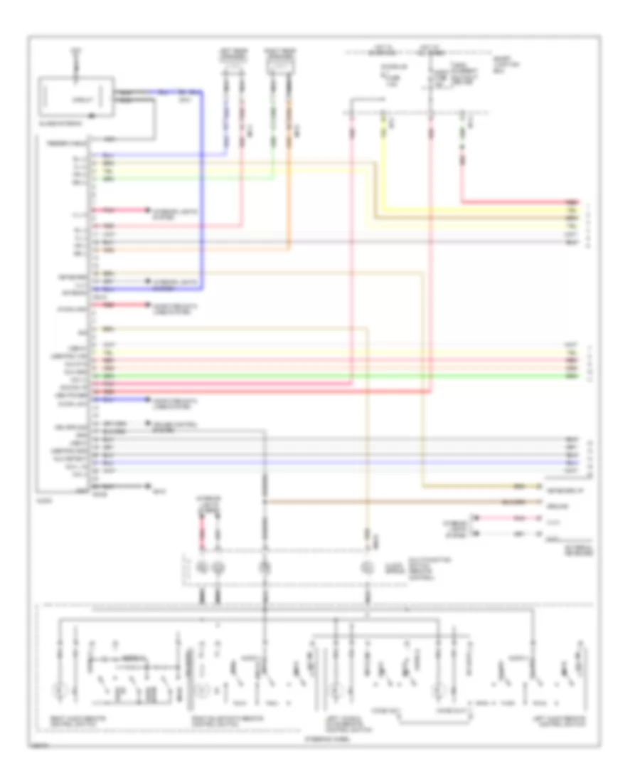 https://portal-diagnostov.com/license.html
Automotive Electricians Portal FZCO
Automotive Electricians Portal FZCO
https://portal-diagnostov.com/license.html
https://portal-diagnostov.com/license.html
Automotive Electricians Portal FZCO
Automotive Electricians Portal FZCOList of elements for Radio Wiring Diagram, without Navigation & Audio Amplifier (1 of 2) for Hyundai Genesis Coupe 2.0T Premium 2013:
- (+)
- (-)
- Acc/on i/p
- Antenna
- Audio
- Audio (+)
- Audio (-)
- Audio (-) call end of
- Audio (-) vol up
- Audio fuse 15a
- Aux detect
- Aux gnd
- Aux l in
- Aux r in
- B/t (in)
- B/t (out)
- Call
- Circuit
- Clock spring
- Computer data lines system
- Cruise control system
- Down seek
- External keyboard
- Feeder cable
- Fl (+)
- Fl (-)
- Fr (+)
- Fr (-)
- Glass antenna
- Gm10
- Gnd
- Ground
- Hot at all times
- Hot in on or acc
- I/p-a
- I/p-c
- Ill
- Ill (+)
- Ill(+)
- Ill(-)
- Interior lights system
- Keyboard
- Keyboard i/p
- Leak current autocut device
- Left audio remote control switch
- Left rear speaker
- Left voice & mute remote control switch
- M-can high
- M-can low
- M03-a
- M03-b
- M48-r
- Mem power
- Mf11
- Mf31
- Mic (+)
- Mic (-)
- Mode
- Module fuse 7.5a
- Multi-function switch (remote control)
- Mute
- Mute (in)
- Nca
- Pnk
- Red
- Right audio remote control switch
- Right rear speaker
- Rl (+)
- Rl (-)
- Rr (+)
- Rr (-)
- Sig
- Smart junction box
- Steering wheel
- Up seek
- Usb d+
- Usb d-
- Usb/ipod gnd
- Usb/ipod vod
- Veh spd sig
- Voice
- Voice (in)
- Voice (out)
- Vol (in)
- Vol (out)
- Vol dw
Radio Wiring Diagram, without Navigation & Audio Amplifier (2 of 2) for Hyundai Genesis Coupe 2.0T Premium 2013
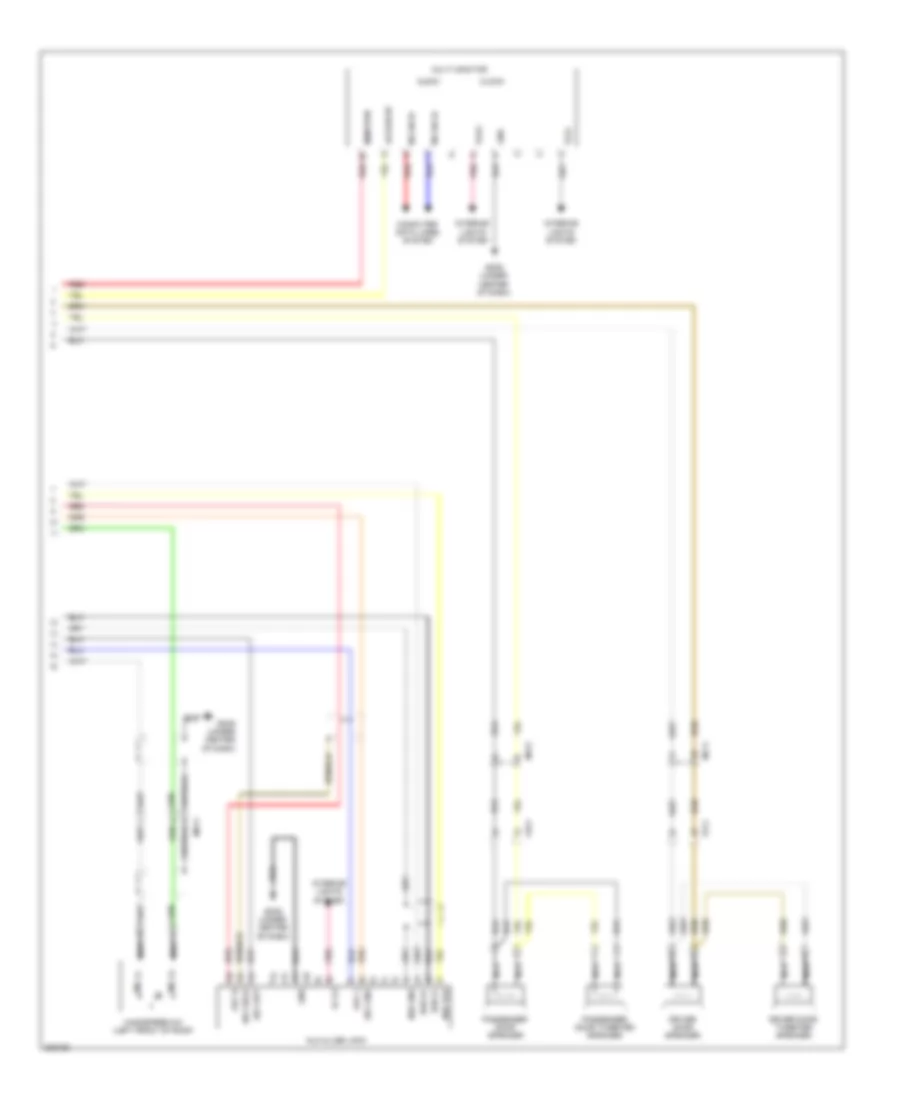 https://portal-diagnostov.com/license.html
Automotive Electricians Portal FZCO
Automotive Electricians Portal FZCO
https://portal-diagnostov.com/license.html
https://portal-diagnostov.com/license.html
Automotive Electricians Portal FZCO
Automotive Electricians Portal FZCOList of elements for Radio Wiring Diagram, without Navigation & Audio Amplifier (2 of 2) for Hyundai Genesis Coupe 2.0T Premium 2013:
- Acc/on i/p
- Audio
- Aux & usb jack
- Aux det
- Aux gnd
- Aux l
- Aux r
- Aux shld
- Clock
- Computer data lines system
- Driver door speaker
- Driver door tweeter speaker
- Fd11
- Fd21
- Gm05 (under center of dash)
- Gnd
- Handsfree mic (left front of roof)
- Ill (+)
- Ill(+)
- Ill(-)
- Interior lights system
- M-can hi
- M-can lo
- Mem pwr
- Mf11
- Mf31
- Mic (+)
- Mic (-)
- Mr11
- Multi monitor
- Nca
- Passenger door speaker
- Passenger door tweeter speaker
- Pnk
- Red
- Usb d+
- Usb d-
- Usb gnd
- Usb vod
Radio Wiring Diagram, without Navigation & with Audio Amplifier (1 of 2) for Hyundai Genesis Coupe 2.0T Premium 2013
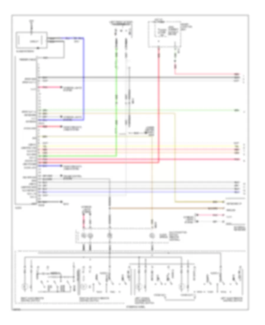 https://portal-diagnostov.com/license.html
Automotive Electricians Portal FZCO
Automotive Electricians Portal FZCO
https://portal-diagnostov.com/license.html
https://portal-diagnostov.com/license.html
Automotive Electricians Portal FZCO
Automotive Electricians Portal FZCOList of elements for Radio Wiring Diagram, without Navigation & with Audio Amplifier (1 of 2) for Hyundai Genesis Coupe 2.0T Premium 2013:
- (+)
- (-)
- (left front of roof) handsfree mic
- (under center of dash) gm05
- Acc/on i/p
- Antenna
- Audio
- Audio (+)
- Audio (-)
- Audio (-) call end of
- Audio (-) vol up
- Audio fuse 15a
- Aux detect
- Aux gnd
- Aux l in
- Aux r in
- B/t (in)
- B/t (out)
- Call
- Circuit
- Clock spring
- Computer data lines system
- Cruise control system
- Down seek
- External keyboard
- Feeder cable
- Glass antenna
- Gm10
- Gnd
- Ground
- Hot at all times
- I/p-a
- Ill
- Ill(+)
- Ill(-)
- Interior lights system
- Keyboard
- Keyboard i/p
- Leak current autocut device
- Left audio remote control switch
- Left voice & mute remote control switch
- M-can high
- M-can low
- M03-a
- M03-b
- M48-r
- Mem power
- Mf31
- Mic (+)
- Mic (-)
- Mode
- Mr11
- Multi-function switch (remote control)
- Mute
- Mute (in)
- Nca
- Pnk
- Red
- Right audio remote control switch
- Sig
- Smart junction box
- Spdif gnd
- Spdif out (+)
- Spdif out (-)
- Steering wheel
- Up seek
- Usb d+
- Usb d-
- Usb/ipod gnd
- Usb/ipod vod
- Veh spd sig
- Voice
- Voice (in)
- Voice (out)
- Vol (in)
- Vol (out)
- Vol dw
Radio Wiring Diagram, without Navigation & with Audio Amplifier (2 of 2) for Hyundai Genesis Coupe 2.0T Premium 2013
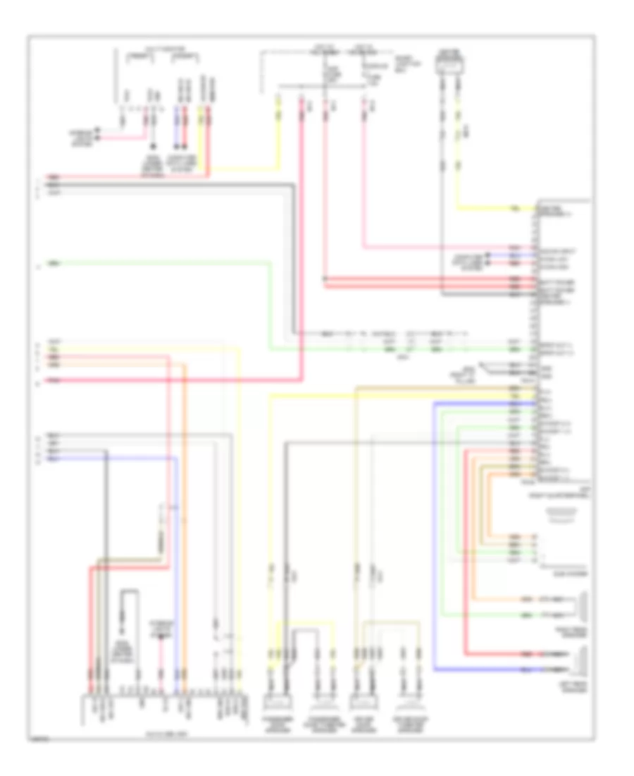 https://portal-diagnostov.com/license.html
Automotive Electricians Portal FZCO
Automotive Electricians Portal FZCO
https://portal-diagnostov.com/license.html
https://portal-diagnostov.com/license.html
Automotive Electricians Portal FZCO
Automotive Electricians Portal FZCOList of elements for Radio Wiring Diagram, without Navigation & with Audio Amplifier (2 of 2) for Hyundai Genesis Coupe 2.0T Premium 2013:
- Acc/on i/p
- Acc/on input
- Amp (right quarterpanel)
- Amp fuse 25a
- Audio
- Aux & usb jack
- Aux det
- Aux gnd
- Aux l
- Aux r
- Aux shld
- Batt power
- Batt power center speaker (-)
- Center
- Center speaker
- Clock
- Computer data lines system
- Driver door speaker
- Driver door tweeter speaker
- F04-a
- F04-b
- Fd11
- Fd21
- Fl(+)
- Fl(-)
- Fr(+)
- Fr(-)
- Gf08 (right "c" pillar)
- Gm05 (under center of dash)
- Gnd
- Hot at all times
- Hot in on or acc
- I/p-c
- I/p-f
- I/p-g
- Ill (+)
- Ill(+)
- Ill(-)
- Interior lights system
- Left rear speaker
- M-can hi
- M-can high
- M-can lo
- M-can low
- Mem pwr
- Mf31
- Module fuse 7.5a
- Multi monitor
- Nca
- Passenger door speaker
- Passenger door tweeter speaker
- Pnk
- Red
- Right rear speaker
- Rl(+)
- Rl(-)
- Rr(+)
- Rr(-)
- S/woof 1 (+)
- S/woof 1 (-)
- S/woof 2 (+)
- S/woof 2 (-)
- Smart junction box
- Spdif out (+)
- Spdif out (-)
- Speaker (+)
- Sub woofer
- Usb d+
- Usb d-
- Usb gnd
- Usb vod
SHIFT INTERLOCK
Shift Interlock Wiring Diagram for Hyundai Genesis Coupe 2.0T Premium 2013
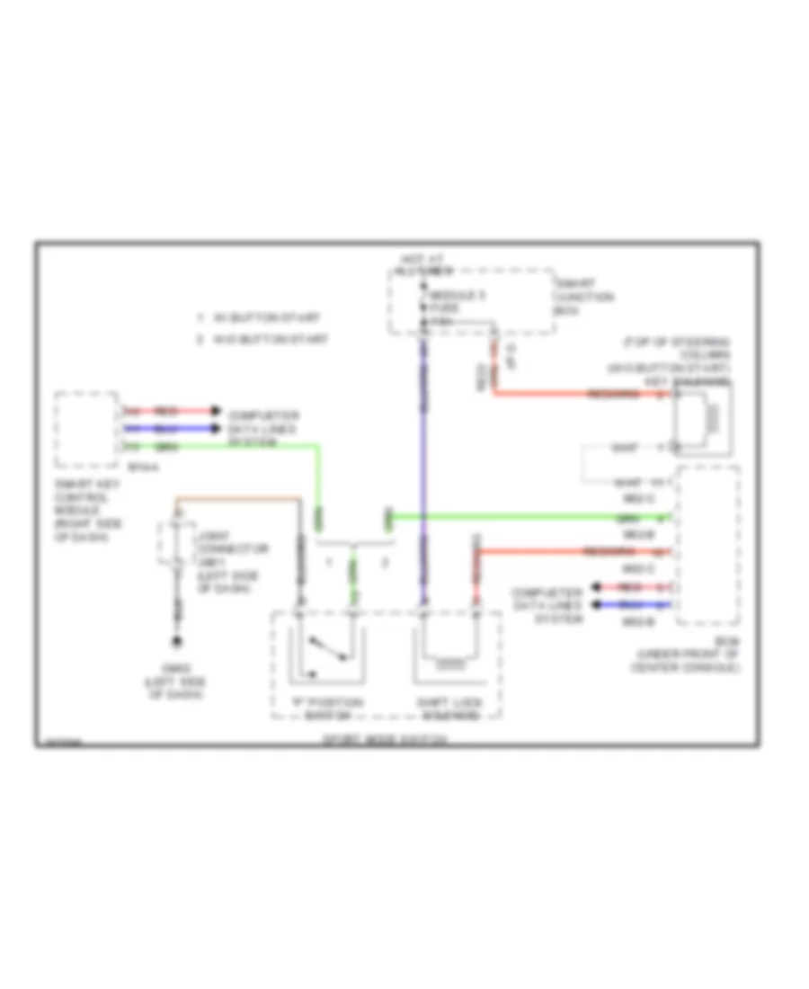 https://portal-diagnostov.com/license.html
Automotive Electricians Portal FZCO
Automotive Electricians Portal FZCO
https://portal-diagnostov.com/license.html
https://portal-diagnostov.com/license.html
Automotive Electricians Portal FZCO
Automotive Electricians Portal FZCOList of elements for Shift Interlock Wiring Diagram for Hyundai Genesis Coupe 2.0T Premium 2013:
- "p" position switch
- (top of steering column) (w/o button start) key solenoid
- Bcm (under front of center console)
- Compueter data lines system
- Gm02 (left side of dash)
- Hot at all times
- I/p-d
- Joint connector jm01 (left side of dash)
- M02-b
- M02-c
- M14-a
- Module 5 fuse 7.5a
- Red
- Shift lock solenoid
- Smart junction box
- Smart key control module (right side of dash)
- Sport mode switch
- W/ button start
- W/o button start
STARTING/CHARGING
Charging Wiring Diagram for Hyundai Genesis Coupe 2.0T Premium 2013
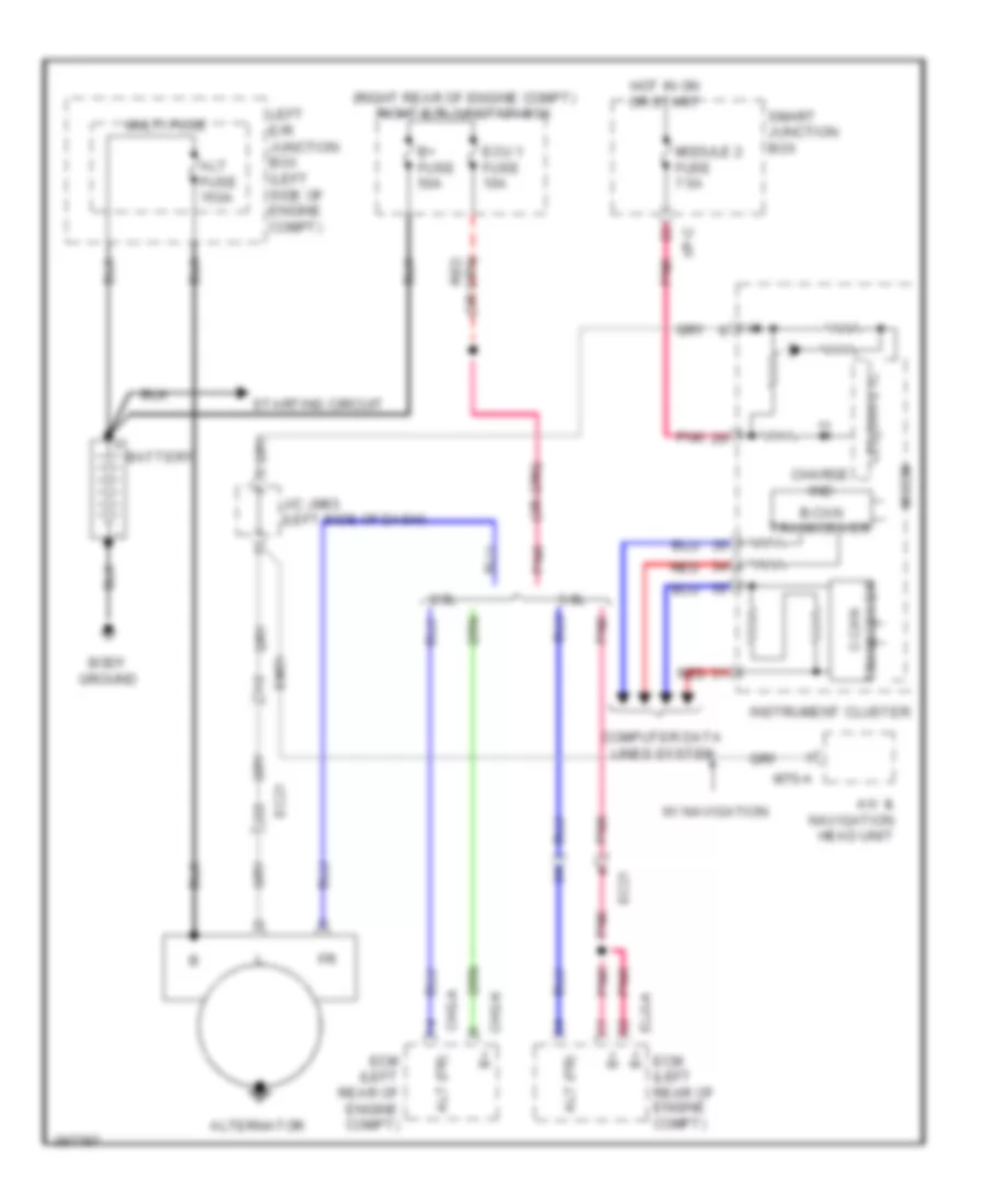 https://portal-diagnostov.com/license.html
Automotive Electricians Portal FZCO
Automotive Electricians Portal FZCO
https://portal-diagnostov.com/license.html
https://portal-diagnostov.com/license.html
Automotive Electricians Portal FZCO
Automotive Electricians Portal FZCOList of elements for Charging Wiring Diagram for Hyundai Genesis Coupe 2.0T Premium 2013:
- (right rear of engine compt) right e/r junction box
- 2.0l
- 3.8l
- A/v & navigation head unit
- Alt (fr)
- Alt fuse 150a
- Alternator
- B+ fuse 50a
- B-can transceiver
- Battery
- Body ground
- Charge ind
- Chg-a
- Chg-k
- Computer data lines system
- Ec21
- Ecm (left rear of engine compt)
- Ecu 1 fuse 10a
- Elg-a
- Em51
- Hot in on or start
- I/p-c
- Instrument cluster
- J/c jm03 (left side of dash)
- Led drive ic
- Left e/r junction box (left side of engine compt)
- M70-a
- Micom
- Module 2 fuse 7.5a
- Multi fuse
- Pnk
- Red
- Smart junction box
- Starting circuit
- Transceiver c-can
- W/ navigation
Starting Wiring Diagram, A/T with Button Start for Hyundai Genesis Coupe 2.0T Premium 2013
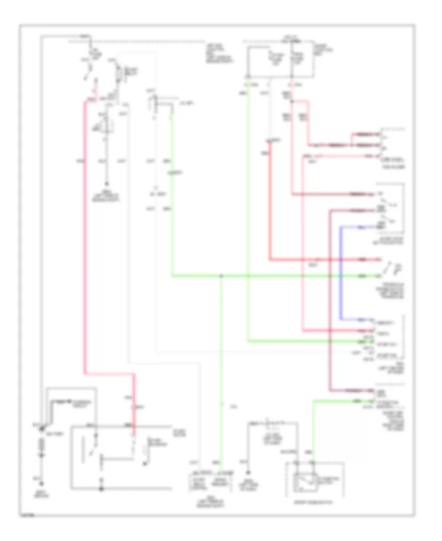 https://portal-diagnostov.com/license.html
Automotive Electricians Portal FZCO
Automotive Electricians Portal FZCO
https://portal-diagnostov.com/license.html
https://portal-diagnostov.com/license.html
Automotive Electricians Portal FZCO
Automotive Electricians Portal FZCOList of elements for Starting Wiring Diagram, A/T with Button Start for Hyundai Genesis Coupe 2.0T Premium 2013:
- 'p' position switch
- 2.0l
- 3.8l
- Battery
- Body ground
- Charging circuit
- Clg-b
- Crank request
- Ec21
- Ecm (left rear of engine compt)
- Elg-a
- Em21
- Fob holder
- Fob in
- Ge04 (left side of engine compt)
- Gm02 (left side of dash)
- Hot at all times
- I/p-b
- I/p-d
- Ill
- J/c je68
- J/c je71
- J/c jm01 (left side of dash)
- Key in sw
- Left e/r junction box (left side of engine compt)
- M14-a
- M51-a
- M51-b
- Mm11
- P/n sw
- Pdm (left center of dash)
- Pdm2 fuse 10a
- Pnk
- Red
- Smart junction box
- Smart key control module (right side of dash)
- Sport mode switch
- Ssb sw-1
- Ssb sw-2
- Start f/b
- Start fuse 10a
- Start motor
- Start relay
- Start relay control
- Start rly
- Start solenoid
- Start stop button switch
- Transaxle range switch (left side of transaxle)
Starting Wiring Diagram, A/T without Button Start for Hyundai Genesis Coupe 2.0T Premium 2013
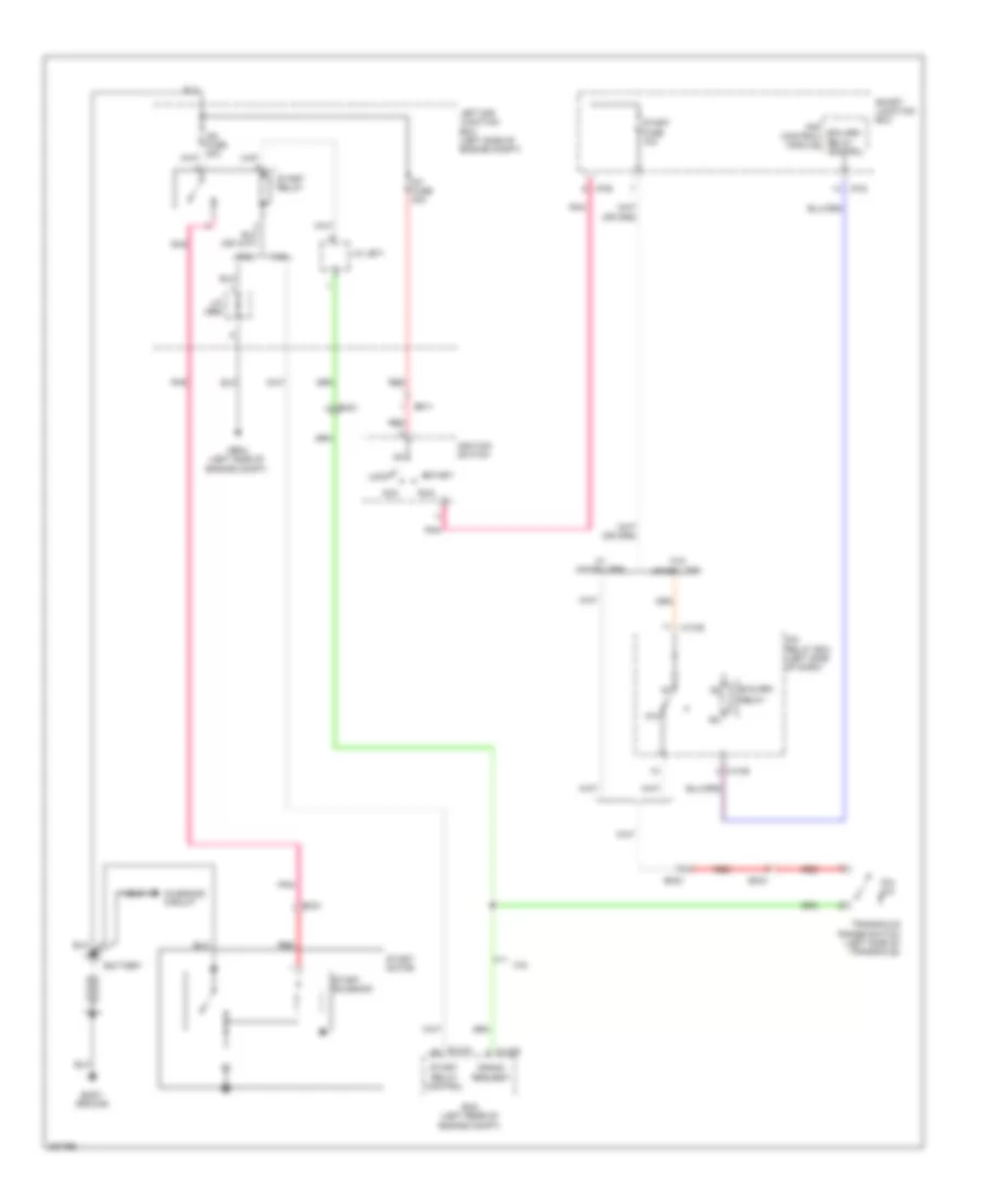 https://portal-diagnostov.com/license.html
Automotive Electricians Portal FZCO
Automotive Electricians Portal FZCO
https://portal-diagnostov.com/license.html
https://portal-diagnostov.com/license.html
Automotive Electricians Portal FZCO
Automotive Electricians Portal FZCOList of elements for Starting Wiring Diagram, A/T without Button Start for Hyundai Genesis Coupe 2.0T Premium 2013:
- 2.0l
- 3.8l
- 87a
- Acc
- B/alarm
- B/alarm relay control
- Battery
- Body ground
- Charging circuit
- Clg-b
- Crank request
- Ec21
- Ecm (left rear of engine compt)
- Elg-a
- Em11
- Em21
- Ge04 (left side of engine compt)
- I/p-b
- I/p-d
- Icm relay box (left side of dash)
- Ig1 fuse 40a
- Ignition switch
- Ips control module
- J/c je68
- J/c je71
- Left e/r junction box (left side of engine compt)
- Lock
- M13-b
- P/n sw
- Pnk
- Red
- Relay
- Run
- Smart junction box
- Start
- Start fuse 10a
- Start motor
- Start relay
- Start relay control
- Start solenoid
- Transaxle range switch (left side of transaxle)
- W/ immobilizer
- W/o immobilizer
Starting Wiring Diagram, M/T with Button Start for Hyundai Genesis Coupe 2.0T Premium 2013
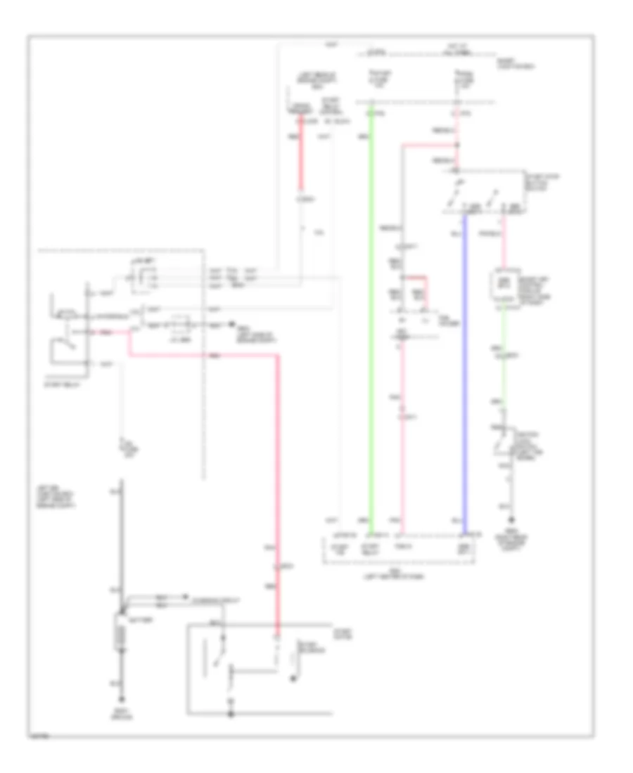 https://portal-diagnostov.com/license.html
Automotive Electricians Portal FZCO
Automotive Electricians Portal FZCO
https://portal-diagnostov.com/license.html
https://portal-diagnostov.com/license.html
Automotive Electricians Portal FZCO
Automotive Electricians Portal FZCOList of elements for Starting Wiring Diagram, M/T with Button Start for Hyundai Genesis Coupe 2.0T Premium 2013:
- (left rear of engine compt) ecm
- 2.0l
- 3.8l
- All times
- Battery
- Body ground
- Charging circuit
- Clg-b
- Clutch
- Crank request
- Ec21
- Elg-a
- Em21
- Fob holder
- Fob in
- Ge04 (left side of engine compt)
- Ge05 (right rear of engine compt)
- Hot at
- I/p-b
- I/p-d
- Ig2 fuse 30a
- Ignition lock switch (left toe board)
- Ill
- J/c je68
- J/c je71
- Key in sw
- Left e/r junction box (left side of engine compt)
- M14-a
- M51-a
- M51-b
- Mm11
- Nca
- Pdm (left center of dash)
- Pdm2 fuse 10a
- Pnk
- Red
- Smart junction box
- Smart key control module (right side of dash)
- Ssb sw-1
- Ssb sw-2
- Start f/b
- Start fuse 10a
- Start motor
- Start relay
- Start relay control
- Start solenoid
- Start stop button switch
Starting Wiring Diagram, M/T without Button Start for Hyundai Genesis Coupe 2.0T Premium 2013
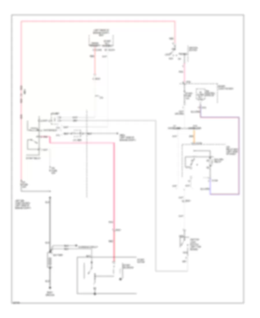 https://portal-diagnostov.com/license.html
Automotive Electricians Portal FZCO
Automotive Electricians Portal FZCO
https://portal-diagnostov.com/license.html
https://portal-diagnostov.com/license.html
Automotive Electricians Portal FZCO
Automotive Electricians Portal FZCOList of elements for Starting Wiring Diagram, M/T without Button Start for Hyundai Genesis Coupe 2.0T Premium 2013:
- (left rear of engine compt) ecm
- 2.0l
- 3.8l
- 87a
- Acc
- B/ alarm rly ctrl
- B/alarm relay
- Battery
- Body ground
- Charging circuit
- Clg-b
- Crank request
- Ec21
- Elg-a
- Em11
- Em21
- Ge04 (left side of engine compt)
- I/p-b
- I/p-d
- Icm relay box (left side of dash)
- Ig1 fuse 40a
- Ig2 fuse 30a
- Ignition lock switch (left toe board)
- Ignition switch
- Ips control module
- J/c je68
- J/c je71
- Left e/r junction box (left side of engine compt)
- Lock
- M13-b
- Nca
- Pnk
- Red
- Smart junction box
- Start
- Start fuse 10a
- Start motor
- Start relay
- Start rly control
- Start solenoid
- W/ immobilizer
- W/o immobilizer
SUPPLEMENTAL RESTRAINTS
Supplemental Restraints Wiring Diagram (1 of 2) for Hyundai Genesis Coupe 2.0T Premium 2013
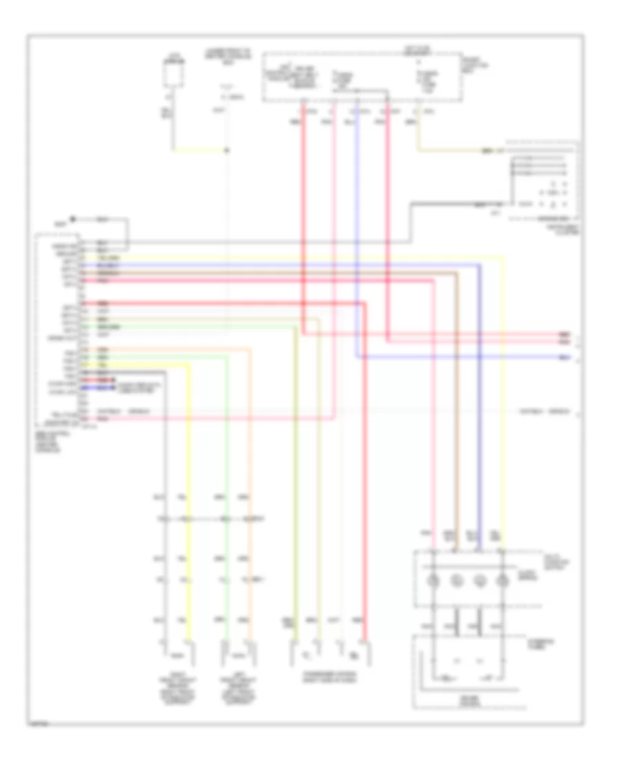 https://portal-diagnostov.com/license.html
Automotive Electricians Portal FZCO
Automotive Electricians Portal FZCO
https://portal-diagnostov.com/license.html
https://portal-diagnostov.com/license.html
Automotive Electricians Portal FZCO
Automotive Electricians Portal FZCOList of elements for Supplemental Restraints Wiring Diagram (1 of 2) for Hyundai Genesis Coupe 2.0T Premium 2013:
- (under front of center console) bcm
- 1st(+)
- 1st(-)
- 2st(+)
- 2st(-)
- A/bag fuse 15a
- A/bag ind
- A/bag ind fuse 7.5a
- Air bag ind
- C-can high
- C-can low
- Clock spring
- Computer data lines system
- Crash out
- Driver air bag
- Driver seat belt buckle switch
- Ee11
- Em21
- Fis(+)
- Fis(-)
- Gm07
- Ground
- Hot in on or start
- I/p-a
- I/p-c
- I/p-f
- I/p-g
- Instrument cluster
- Ips control module
- Left front impact sensor (left front of radiator support)
- M02-a
- M11
- M71-a
- Mts module
- Multi- function switch
- Nca
- On/start in
- Passenger air bag (right side of dash)
- Pnk
- Red
- Right front impact sensor (right front of radiator support)
- Smart junction box
- Srs control module (center console)
- Steering wheel
- Telltale
Supplemental Restraints Wiring Diagram (2 of 2) for Hyundai Genesis Coupe 2.0T Premium 2013
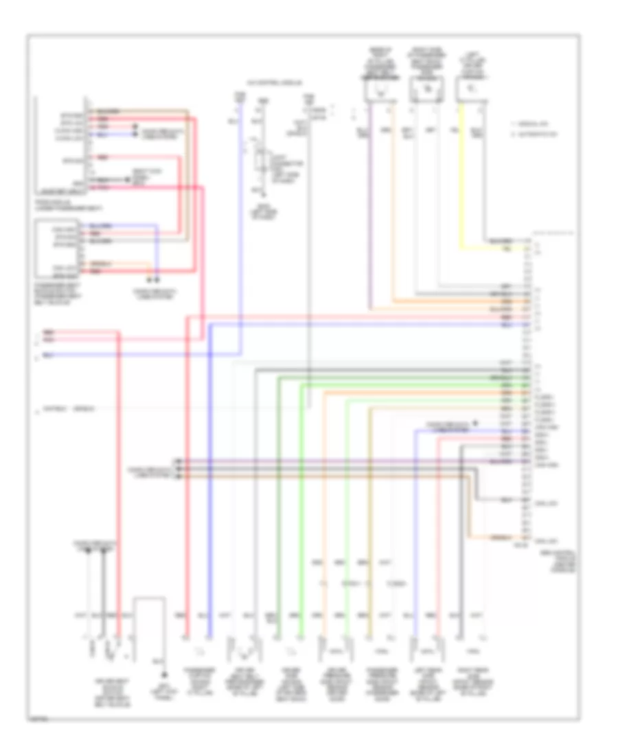 https://portal-diagnostov.com/license.html
Automotive Electricians Portal FZCO
Automotive Electricians Portal FZCO
https://portal-diagnostov.com/license.html
https://portal-diagnostov.com/license.html
Automotive Electricians Portal FZCO
Automotive Electricians Portal FZCOList of elements for Supplemental Restraints Wiring Diagram (2 of 2) for Hyundai Genesis Coupe 2.0T Premium 2013:
- (+)
- (-)
- (base of right "b" pillar) passenger seat belt pretensioner
- (left "c" pillar) driver curtain air bag
- (right kick panel) gf05
- (right side of passenger seat back) passenger side air bag
- A/c control module
- Automatic a/c
- Bts gnd
- Bts sig
- Bts vcc
- C-can high
- C-can low
- Can hi
- Can high
- Can lo
- Can low
- Computer data lines system
- Driver pressure side impact sensor (driver door)
- Driver seat belt pretensioner (base of left "b" pillar)
- Driver seat buckle switch (driver seat belt buckle)
- Driver side air bag (left side of driver's seat back)
- F81-b
- Fd11
- Fd21
- Gf01 (left kick panel)
- Gm02 (left side of dash)
- Gnd
- Joint connector jm01 (left side of dash)
- Left rear side impact sensor (base of left "b" pillar)
- M06-b
- M07-b
- Manual a/c
- On/start input
- Pab ign1
- Pab sig
- Passenger curtain air bag (right "c" pillar)
- Passenger pressure side impact sensor (passenger door)
- Passenger seat buckle switch (passenger seat belt buckle)
- Pnk
- Pods module (under passenger seat)
- P_sis(+)
- P_sis(-)
- Red
- Right rear side impact sensor (base of right "b" pillar)
- Sis(+)
- Sis(-)
- Srs control module (center console)
TRANSMISSION
Transmission Wiring Diagram (1 of 2) for Hyundai Genesis Coupe 2.0T Premium 2013
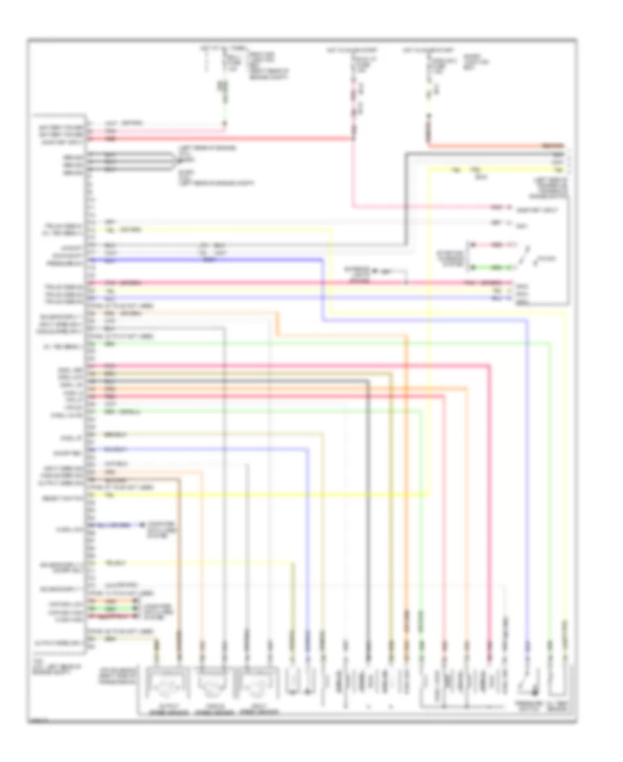 https://portal-diagnostov.com/license.html
Automotive Electricians Portal FZCO
Automotive Electricians Portal FZCO
https://portal-diagnostov.com/license.html
https://portal-diagnostov.com/license.html
Automotive Electricians Portal FZCO
Automotive Electricians Portal FZCOList of elements for Transmission Wiring Diagram (1 of 2) for Hyundai Genesis Coupe 2.0T Premium 2013:
- (0r pnk)
- (left rear of engine) (2.0l) ghg03
- (left side of transaxle) transaxle range switch
- (or pnk)
- (pins: 24 to 28 not used)
- (pins: 32 to 37 not used)
- (pins: 57 to 60 not used)
- (pins: 74 to 84 not used)
- (pins: 88 to 92 not used)
- Atm solenoid (right side of transmission)
- B/up lp fuse 15a
- Battery power
- C-can high
- C-can low
- Ccp-can high
- Ccp-can low
- Computer data lines system
- D-sol 27
- D-sol 35r
- D-sol 4 & od
- D-sol 6
- D-sol 8lr
- D-sol ud
- Down shift
- Ec21
- Ecu 1 fuse 10a
- Exterior lights system
- Glg03 (3.8l) (left rear of engine compt)
- Ground
- Hot at all times
- Hot in on or start
- I/p-c
- I/p-e
- Input sped sig
- Input sped sply
- Input speed sensor
- Middle sped sig
- Middle sped sply
- Middle speed sensor
- Module 2 fuse 7.5a
- Oil tem sens (+)
- Oil tem sens (-)
- Oil temp sensor
- On/off rev
- On/start input
- Output sped sig
- Output sped sply
- Output speed sensor
- P/n sw
- Pnk
- Pressure sw
- Pressure switch
- Red
- Right e/r junction box (right rear of engine compt)
- Select switch
- Sig 1
- Sig 2
- Sig 3
- Sig 4
- Smart junction box
- Solenoid sply 1
- Solenoid sply 2 (on/off sol)
- Starting/ charging system
- Tcm (2.0l: left rear of engine compt)
- Trxle code s1
- Trxle code s2
- Trxle code s3
- Trxle code s4
- Up shift
- Vfs dc
- Vfs lp
- Vfs-dc
Transmission Wiring Diagram (2 of 2) for Hyundai Genesis Coupe 2.0T Premium 2013
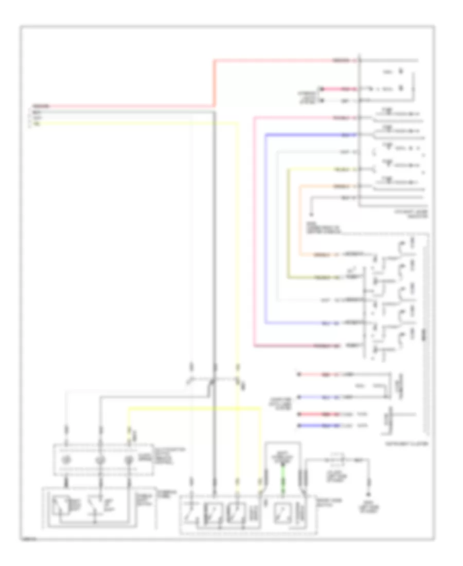 https://portal-diagnostov.com/license.html
Automotive Electricians Portal FZCO
Automotive Electricians Portal FZCO
https://portal-diagnostov.com/license.html
https://portal-diagnostov.com/license.html
Automotive Electricians Portal FZCO
Automotive Electricians Portal FZCOList of elements for Transmission Wiring Diagram (2 of 2) for Hyundai Genesis Coupe 2.0T Premium 2013:
- At d out
- At n out
- At p out
- At r out
- At s out
- Atm shift lever indicator
- B-can transceiver
- C-can transceiver
- Clock spring
- Computer data lines system
- D ind
- Down shift
- Em21
- Gm02 (left side of dash)
- Gm06 (under front of center console)
- Gnd
- High
- Ig1
- Ill (+)
- Ill (-)
- Instrument cluster
- Interior lights system
- J/c jm01 (left side of dash)
- Left up shift
- Low
- M48-r
- Micom
- Multi-function switch (remote control)
- N ind
- Nca
- P ind
- Paddle shift switch
- Pnk
- R ind
- Red
- Right down shift
- S gnd
- S ind
- Shift interlock system
- Sport mode switch
- Steering wheel
- Switch 'p' position
- Switch select
- Up shift
TRUNK, TAILGATE, FUEL DOOR
Trunk & Fuel Door Release Wiring Diagram for Hyundai Genesis Coupe 2.0T Premium 2013
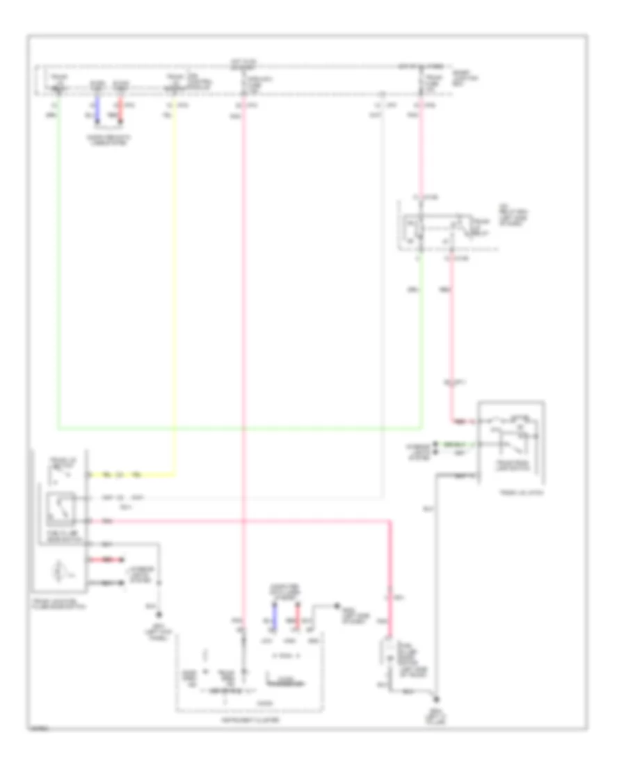 https://portal-diagnostov.com/license.html
Automotive Electricians Portal FZCO
Automotive Electricians Portal FZCO
https://portal-diagnostov.com/license.html
https://portal-diagnostov.com/license.html
Automotive Electricians Portal FZCO
Automotive Electricians Portal FZCOList of elements for Trunk & Fuel Door Release Wiring Diagram for Hyundai Genesis Coupe 2.0T Premium 2013:
- B can high
- B can low
- C-can transceiver
- Computer data lines system
- Door open ind
- Fd11
- Fuel filler door motor (left side of trunk)
- Fuel filler door switch
- Gf01 (left kick panel)
- Gf04 (left "c" pillar)
- Gm02 (left side of dash)
- Gnd
- High
- Hot at all times
- Hot in on or start
- I/p-b
- I/p-c
- I/p-d
- I/p-f
- I/p-g
- Icm relay box (left side of dash)
- Ill
- Instrument cluster
- Interior lights system
- Ips control module
- Led drive ic
- Low
- M13-b
- Mf11
- Micom
- Module 2 fuse 7.5a
- Motor
- Pnk
- Ptc
- Red
- Smart junction box
- Trunk fuse 10a
- Trunk lid & fuel filler door switch
- Trunk lid latch
- Trunk lid relay
- Trunk lid switch
- Trunk open ind
- Trunk room lamp switch
WARNING SYSTEMS
Chime Wiring Diagram for Hyundai Genesis Coupe 2.0T Premium 2013
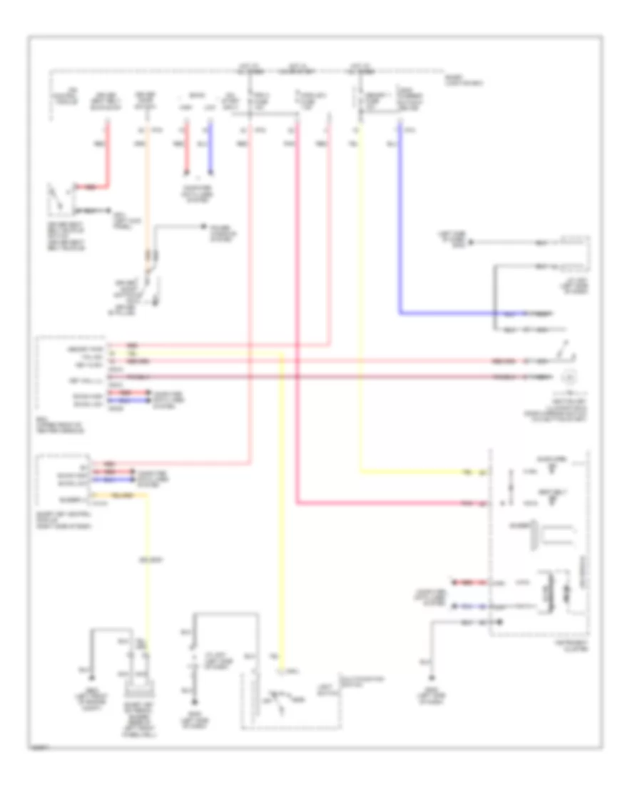 https://portal-diagnostov.com/license.html
Automotive Electricians Portal FZCO
Automotive Electricians Portal FZCO
https://portal-diagnostov.com/license.html
https://portal-diagnostov.com/license.html
Automotive Electricians Portal FZCO
Automotive Electricians Portal FZCOList of elements for Chime Wiring Diagram for Hyundai Genesis Coupe 2.0T Premium 2013:
- (left side of dash)
- (left side of dash) gm02
- B-can
- B-can high
- B-can low
- Bcm (upper front of center console)
- Buzzer
- Buzzer (+)
- Computer data lines system
- Door open ind
- Driver door switch
- Driver door switch (on driver "b" pillar)
- Driver seat belt buckle sw
- Driver seat belt buckle switch (driver seat belt buckle)
- Em51
- Ge03 (left front of engine compt)
- Gf01 (left kick panel)
- Gm02 (left side of dash)
- Head
- High
- Hot at all times
- Hot in on or start
- I/p-c
- I/p-d
- I/p-g
- Ignition key illumination & door warning switch (w/o button start)
- Ill
- Instrument cluster
- Ips control module
- J/c jm01
- J/c jm01 (left side of dash)
- Key hall ill
- Key in sw
- Leak current autocut device
- Led drive ic
- Light switch
- Low
- M02-a
- M02-b
- M02-c
- M14-a
- M48-l
- Memory 1 fuse 10a
- Memory pwr
- Micom
- Module 2 fuse 7.5a
- Multi-function switch
- Nca
- Off
- On/ start input
- Pdm 2 fuse 10a
- Pnk
- Power windows system
- Red
- Seat belt ind
- Smart junction box
- Smart key control module (right side of dash)
- Smart key external buzzer (rear of left front wheelwell)
- Tail
- Tail sw
- Transceiver b-can
Tire Pressure Monitoring Wiring Diagram for Hyundai Genesis Coupe 2.0T Premium 2013
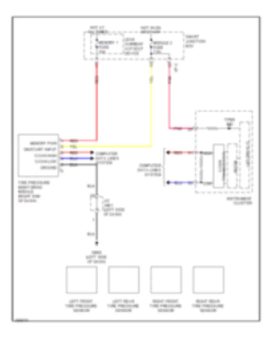 https://portal-diagnostov.com/license.html
Automotive Electricians Portal FZCO
Automotive Electricians Portal FZCO
https://portal-diagnostov.com/license.html
https://portal-diagnostov.com/license.html
Automotive Electricians Portal FZCO
Automotive Electricians Portal FZCOList of elements for Tire Pressure Monitoring Wiring Diagram for Hyundai Genesis Coupe 2.0T Premium 2013:
- C-can high
- C-can low
- Computer data lines system
- Gm02 (left side of dash)
- Ground
- High
- Hot at all times
- Hot in on or start
- I/p-c
- Instrument cluster
- J/c jm01 (left side of dash)
- Leak current autocut device
- Led drive ic
- Left front tire pressure sensor
- Left rear tire pressure sensor
- Low
- Memory 1 fuse 10a
- Memory pwr
- Micom
- Module 2 fuse 7.5a
- On/start input
- Pnk
- Red
- Right front tire pressure sensor
- Right rear tire pressure sensor
- Smart junction box
- Tire pressure monitoring module (right end of dash)
- Tpms ind
- Transceiver c-can
WIPER/WASHER
Wiper/Washer Wiring Diagram for Hyundai Genesis Coupe 2.0T Premium 2013
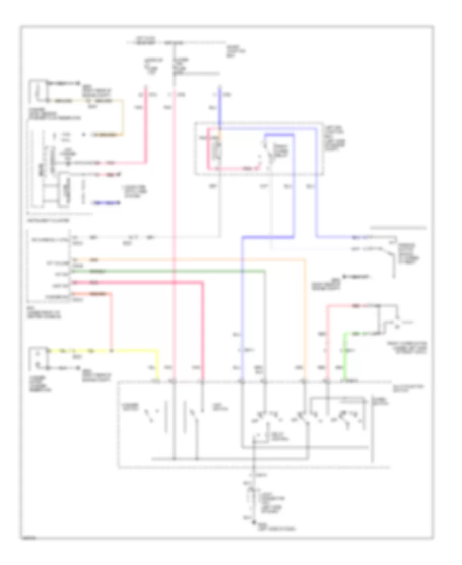 https://portal-diagnostov.com/license.html
Automotive Electricians Portal FZCO
Automotive Electricians Portal FZCO
https://portal-diagnostov.com/license.html
https://portal-diagnostov.com/license.html
Automotive Electricians Portal FZCO
Automotive Electricians Portal FZCOList of elements for Wiper/Washer Wiring Diagram for Hyundai Genesis Coupe 2.0T Premium 2013:
- (left side of dash)
- Bcm (under front of center console)
- C-can transceiver
- Computer data lines system
- Delay control
- Em11
- Em21
- Em51
- Fr wiper rly ctrl
- Front wiper motor (under left side of front cowl)
- Front wiper relay
- Ge02 (right rear of engine compt)
- Ge05 (right rear of engine compt)
- Gm02 (left side of dash)
- Hot in on
- Hot in on or start
- I/p-b
- I/p-c
- I/p-e
- Instrument cluster
- Int
- Int sw
- Int volume
- Joint connector jm01
- Led drive ic
- Left e/r junction box (left side of engine compt)
- Low washer ind
- M02-a
- M02-b
- M02-c
- M48-w
- Micom
- Mist sw
- Mist switch
- Module fuse 7.5a
- Multi-function switch
- Off
- Parking switch (shown w/ wipers at rest)
- Pnk
- Red
- Smart junction box
- Washer level sensor (washer fluid reservoir)
- Washer motor (washer reservoir)
- Washer sw
- Washer switch
- Wiper (fr) fuse 25a
- Wiper switch

 Čeština
 Dansk
Dansk Deutsch
 Ελληνικά
 English
 English
 Español
 Suomi
Suomi Français
 Français
 עברית
עברית Hrvatski
 Magyar
 Italiano
 한국어
한국어 Nederlands
 Polski
 Português
 Português
 Română
 Русский
 Slovenčina
 Slovenščina
 Svenska
 Türkçe
 中文 (中国)
