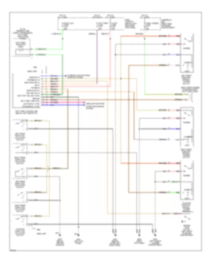
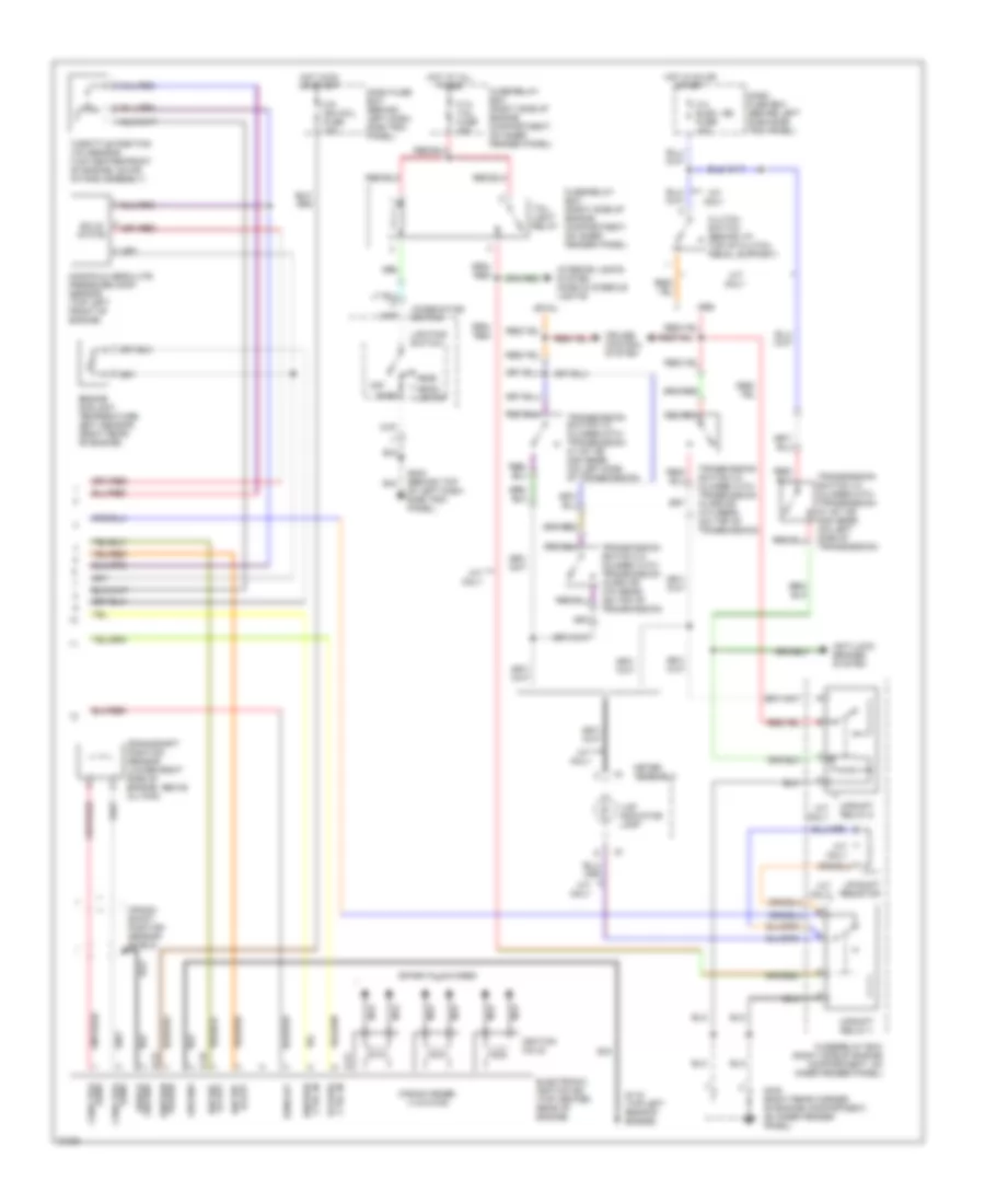
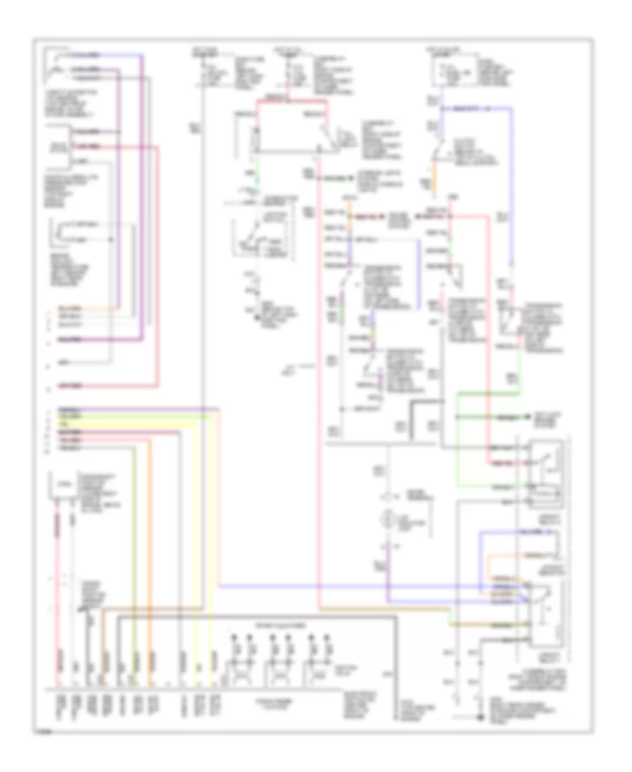
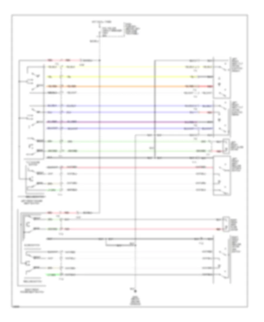
AIR CONDITIONING
A/C Wiring Diagram for Isuzu Trooper Limited 1995
 https://portal-diagnostov.com/license.html
Automotive Electricians Portal FZCO
Automotive Electricians Portal FZCO
https://portal-diagnostov.com/license.html
https://portal-diagnostov.com/license.html
Automotive Electricians Portal FZCO
Automotive Electricians Portal FZCO
List of elements for A/C Wiring Diagram for Isuzu Trooper Limited 1995:
- (1995)
- (1996)
- A/c
- A/c compressor relay (in fuse/ relay box)
- A/c pressure switch (behind left side of radiator grille)
- A/c switch
- A/c thermo
- A/c thermostat relay (in fuse/ relay box)
- B14
- Blower motor
- Blower resistors (behind glove box)
- Blower switch
- C 1995 vftc
- C-91
- Clutch
- Compressor
- Compressor)
- Dash fuse box
- E15
- Electronic thermostat unit (behind glove box)
- Engine control module (behind front of front console)
- Evaporator thermosensor
- Fl-1 (main) 80a
- Fuse c-19 25a
- Fuse c-20 10a
- Fuse/ relay box
- G201 (above right dash side trim panel)
- G202 (top of left dash side trim panel)
- Heater and a/c relay (in dash fuse box)
- Heater-a/c control panel
- Hot at all times
- Off
- Only
- Sensor (in a/c
- Solid state
- Starter relay
- Transmission control module (at top of left kick panel)
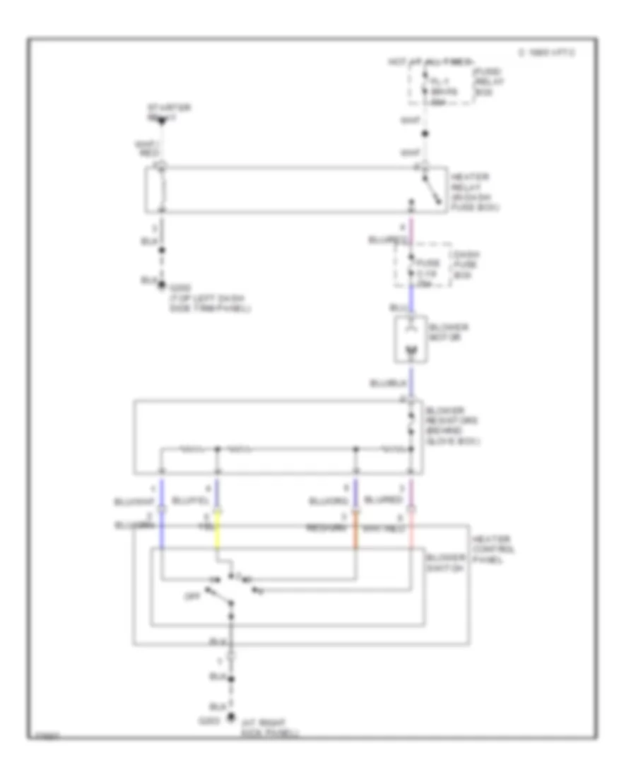
Heater Wiring Diagram for Isuzu Trooper Limited 1995
 https://portal-diagnostov.com/license.html
Automotive Electricians Portal FZCO
Automotive Electricians Portal FZCO
https://portal-diagnostov.com/license.html
https://portal-diagnostov.com/license.html
Automotive Electricians Portal FZCO
Automotive Electricians Portal FZCOList of elements for Heater Wiring Diagram for Isuzu Trooper Limited 1995:
- (at right kick panel)
- Blower motor
- Blower resistors (behind glove box)
- Blower switch
- C 1995 vftc
- Dash fuse box
- Fl-1 (main) 80a
- Fuse c-19 25a
- Fuse/ relay box
- G202 (top left dash side trim panel)
- G203
- Heater control panel
- Heater relay (in dash fuse box)
- Hot at all times
- Off
- Starter relay
ANTI-LOCK BRAKES
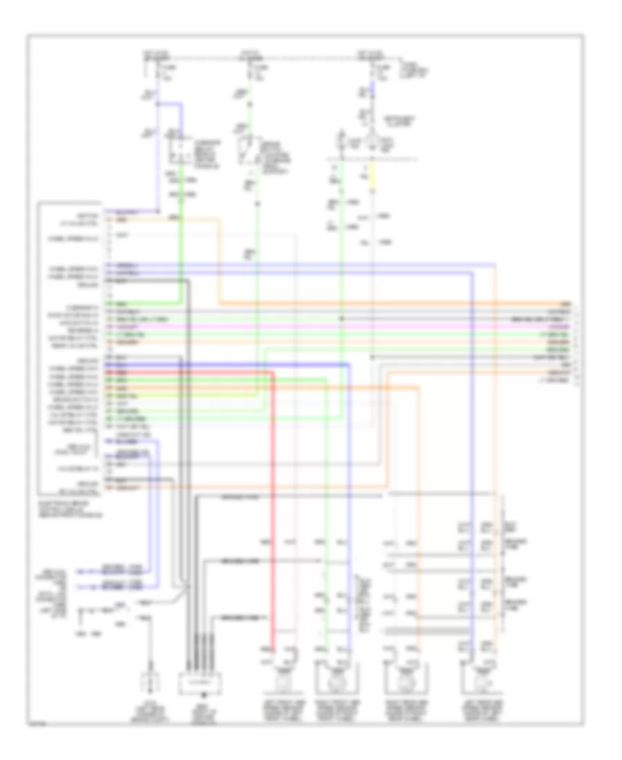
All-Wheel ABS Wiring Diagram (1 of 2) for Isuzu Trooper Limited 1995
 https://portal-diagnostov.com/license.html
Automotive Electricians Portal FZCO
Automotive Electricians Portal FZCO
https://portal-diagnostov.com/license.html
https://portal-diagnostov.com/license.html
Automotive Electricians Portal FZCO
Automotive Electricians Portal FZCOList of elements for All-Wheel ABS Wiring Diagram (1 of 2) for Isuzu Trooper Limited 1995:
- (1995)
- (1996)
- (1996) (1995)
- (mounted on brake
- 4wd ind.
- 4wd switch in
- Abs aldl
- Abs aldl connector (1995) or data link connector (1996) (left side of i/p)
- Abs ind. ctrl
- Anti- lock ind.
- Braided wire
- Brake switch
- Brake switch in
- Cluster
- Conn, in/out
- Dash fuse box (left i/p)
- Electronic brake control module (behind front console)
- Fuse 10a
- Fuse 15a
- Fuse 7.5a
- G sensor in
- G-sensor (below rear of center console)
- G104 (left rear corner of engine compt)
- G206 (right of center console)
- Ground
- Hot at all times
- Hot in on or start
- Ignition
- Instrument
- Left front abs speed sensor (inside of left front wheel)
- Left rear abs speed sensor (inside of left rear wheel)
- Lf valve ctrl
- Motor relay ctrl
- Pedal
- Pump motor run in
- Rear valve ctrl
- Red
- Reverse in
- Rf valve ctrl
- Right front abs speed sensor (inside of right front wheel)
- Right rear abs speed sensor (inside of right rear wheel)
- Support)
- Valve relay ctrl
- Valve relay in
- Wheel speed in-hi
- Wheel speed in-lo
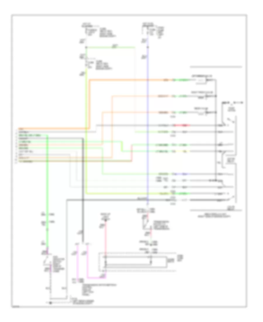
All-Wheel ABS Wiring Diagram (2 of 2) for Isuzu Trooper Limited 1995
 https://portal-diagnostov.com/license.html
Automotive Electricians Portal FZCO
Automotive Electricians Portal FZCO
https://portal-diagnostov.com/license.html
https://portal-diagnostov.com/license.html
Automotive Electricians Portal FZCO
Automotive Electricians Portal FZCOList of elements for All-Wheel ABS Wiring Diagram (2 of 2) for Isuzu Trooper Limited 1995:
- (1995)
- (1995) b10
- (1996)
- (1996) a12
- (left rear corner of engine compt)
- (right side of engine compt)
- 4wd indicator switch (right side of transfer case)
- A/t
- Abs hydraulic unit
- All times
- Back up light switch
- C103
- C104
- Dash fuse box
- Dash fuse box (left
- Diode box 6
- Fuse 20a
- Fuse c-4 10a
- Fuse/ relay box (right side engine compt)
- Fusible link 6 40a
- G116
- Hot at
- Hot in on or start
- I/p)
- Left front valve
- M/t
- Motor relay
- Pump motor
- Rear valve
- Red
- Red/
- Right front valve
- Transmission or powertrain control module (left kick panel)
- Transmission switch 1-2 (left side of transmission)
- Valve relay
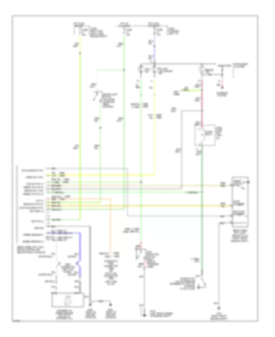
Rear Wheel ABS Wiring Diagram for Isuzu Trooper Limited 1995
 https://portal-diagnostov.com/license.html
Automotive Electricians Portal FZCO
Automotive Electricians Portal FZCO
https://portal-diagnostov.com/license.html
https://portal-diagnostov.com/license.html
Automotive Electricians Portal FZCO
Automotive Electricians Portal FZCOList of elements for Rear Wheel ABS Wiring Diagram for Isuzu Trooper Limited 1995:
- (1995 a/t) (1996,1995 m/t)
- (1995)
- (1995) (1996)
- (1996)
- (1996) (1995)
- (1996,1995 m/t) (1995 a/t)
- (left rear corner of engine compt)
- (left side of i/p)
- (mounted on brake
- (not used)
- 4wd ind.
- 4wd indicator switch (right side of transfer case)
- 4wd switch in
- Battery in
- Brake ind.
- Brake ind. ctrl
- Brake light
- Brake switch in
- Brake valve (right front
- Charging system
- Combination valve pressure differential switch (in brake fluid valve)
- Dash fuse box (left
- Dash fuse box (left i/p)
- Diagnostic test connector (1995) or data link connector (1996)
- Differential speed sensor (on top of differential)
- Diode box 5
- Dtc in
- Dump solenoid
- Dump solenoid ctrl
- Engine compt)
- Fuse 10a
- Fuse 15a
- Fuse 20a
- Fuse/ relay box (right side engine compt)
- G101 (right front engine compt)
- G116
- G206 (right of center console)
- Ground
- Hot at all times
- Hot in on
- Hot in on or start
- I/p)
- Ignition in
- Indicators
- Instrument cluster
- Iso solenoid ctrl
- Isolation solenoid
- Only
- Or acc
- Pedal
- Pnk
- Press. switch in
- Rabs ind. ctrl
- Rear wheel anti-lock
- Rear wheel anti-lock brake controller (behind front console)
- Red/
- Reset switch
- Reset switch in
- Rr. anti- lock brake ind.
- Speed sensor-hi
- Speed sensor-lo
- Support)
- Switch
ANTI-THEFT
Anti-theft Wiring Diagram for Isuzu Trooper Limited 1995
 https://portal-diagnostov.com/license.html
Automotive Electricians Portal FZCO
Automotive Electricians Portal FZCO
https://portal-diagnostov.com/license.html
https://portal-diagnostov.com/license.html
Automotive Electricians Portal FZCO
Automotive Electricians Portal FZCOList of elements for Anti-theft Wiring Diagram for Isuzu Trooper Limited 1995:
- (right rear corner of engine compt) anti-theft horn
- 1996 & 1997
- A/t oil temperature, check transmission, anti-theft indicators panel
- Anti-theft controller (below left side of i/p)
- Anti-theft fuse c-13 10a
- Anti-theft hrn ctrl
- Anti-theft indicator light
- Anti-thft ind lght ctrl
- Clock fuse c-16 10a
- Dash fuse box (behind left dash side trim panel)
- Door lock fuse c-18 20a
- Door sw in
- Door unlck in
- Eng hood opn in
- Engine hood switch (left front of engine compartment)
- Fuse/relay box (right side of engine compartment)
- G200 (left kick panel)
- G202 (behind lower left dash panel)
- G203 (right kick panel)
- G302 (below center console)
- G400 (left side of luggage compartment)
- Ground
- Headlights system
- Horn, hazard fuse f-3 15a
- Hot at all times
- Hot in acc or on
- Ign in
- Interior lights system (door switches)
- Key det sw in
- Left front door key detect/ tamper switch
- Left front door lock actuator/ switch
- Left rear door lock actuator/ switch
- Lighting rly ctrl
- Lock
- Power in
- Red
- Right front door key detect/ tamper switch
- Right front door lock actuator/ switch
- Right rear door lock actuator/ switch
- Starter rly ctrl
- Starting/charging system
- Tailgate door key detect/ tamper switch
- Tailgate door lock actuator/ switch
- Tamper
- Tamper sw in
- Unlock
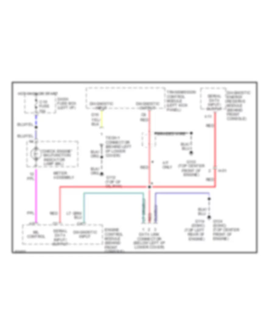
COMPUTER DATA LINES
Computer Data Lines for Isuzu Trooper Limited 1995
 https://portal-diagnostov.com/license.html
Automotive Electricians Portal FZCO
Automotive Electricians Portal FZCO
https://portal-diagnostov.com/license.html
https://portal-diagnostov.com/license.html
Automotive Electricians Portal FZCO
Automotive Electricians Portal FZCOList of elements for Computer Data Lines for Isuzu Trooper Limited 1995:
- "check engine" malfunction indicator lamp (mil)
- A/t only
- A11
- Braided wire
- C-10 fuse 10a
- D16
- Dash fuse box (left i/p)
- Data link connector (below left i/p lower cover)
- Diagnostic energy reserve module (behind front console)
- Diagnostic input
- Diagnostic output
- Engine control module (behind front console)
- Front of engine)
- G112 (top of oil pan)
- G114 (dohc) (top left rear of engine)
- G133 (top center
- G134 (sohc) (top center front of engine)
- H-51
- Hot in on or start
- Meter assembly
- Mil control
- Red
- Serial data input/ output
- Tech-1 connector (behind left i/p lower cover)
- Transmission control module (left kick panel)
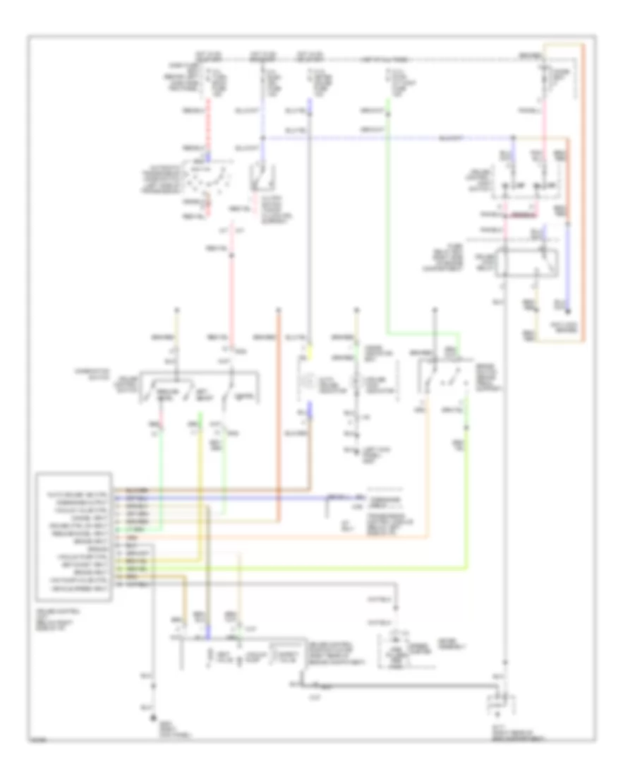
CRUISE CONTROL
Cruise Control Wiring Diagram for Isuzu Trooper Limited 1995
 https://portal-diagnostov.com/license.html
Automotive Electricians Portal FZCO
Automotive Electricians Portal FZCO
https://portal-diagnostov.com/license.html
https://portal-diagnostov.com/license.html
Automotive Electricians Portal FZCO
Automotive Electricians Portal FZCOList of elements for Cruise Control Wiring Diagram for Isuzu Trooper Limited 1995:
- "auto cruise" ind ctrl
- (left kick panel) g200
- A/t
- A/t only
- Anti-lock brakes
- Auto cruise indicator
- Automatic transmission mode switch (left side of transmission)
- B-52
- Brake input
- Brake switch (brake pedal support)
- C-10 meter gauge fuse 10a
- C-14 stop a/t cont fuse 15a
- C-3 turn back fuse 15a
- C-37
- C-4 elec. ign. fuse 10a
- C-90
- Cancel
- Cancel input
- Clutch switch (top of clutch pdl support)
- Combination switch
- Cruise control main switch
- Cruise control pump/actuator (right rear of engine compatment)
- Cruise control switch
- Cruise control unit (below right side of i/p)
- Cruise ctrl on input
- Cruise main indicator
- Cruise main relay
- Dash fuse box (behind left dash side trim panel
- Diode box
- Disengage input
- Disengage output
- Fuse/ relay box (right side of engine compartment)
- G117 (right rear of eng compartment)
- G203 (right kick panel)
- Ground
- Hot at all times
- Hot in on or start
- I-10
- I-40
- Inside indicator box
- M/t
- Meter assembly
- Off
- Pulses per mile
- Red
- Resume/ accel
- Resume/accel input
- Safety valve
- Set/ coast
- Set/coast input
- Speed- ometer
- Transmission control module (below left side of i/p)
- Vac pump/valve ctrl
- Vacuum pump
- Vacuum pump ctrl
- Vacuum valve ctrl
- Vehicle speed input
- Vent valve
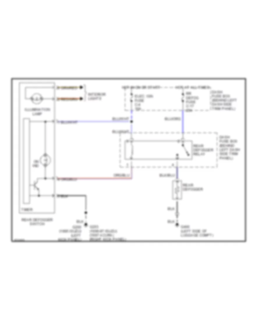
DEFOGGERS
Defogger Wiring Diagram for Isuzu Trooper Limited 1995
 https://portal-diagnostov.com/license.html
Automotive Electricians Portal FZCO
Automotive Electricians Portal FZCO
https://portal-diagnostov.com/license.html
https://portal-diagnostov.com/license.html
Automotive Electricians Portal FZCO
Automotive Electricians Portal FZCOList of elements for Defogger Wiring Diagram for Isuzu Trooper Limited 1995:
- Dash fuse box (behind left dash side trim panel)
- Elec. ign. fuse c-4 10a
- G200 (1995 isuzu) (left kick panel)
- G203 (1996-97 isuzu) (1997 acura) (right kick panel)
- G400 (left side of luggage compt)
- Hot at all times
- Hot in on or start
- Illumination lamp
- Interior lights
- On ind
- Rear defogger
- Rear defogger relay
- Rear defogger switch
- Rr defog fuse c-17 25a
- Timer
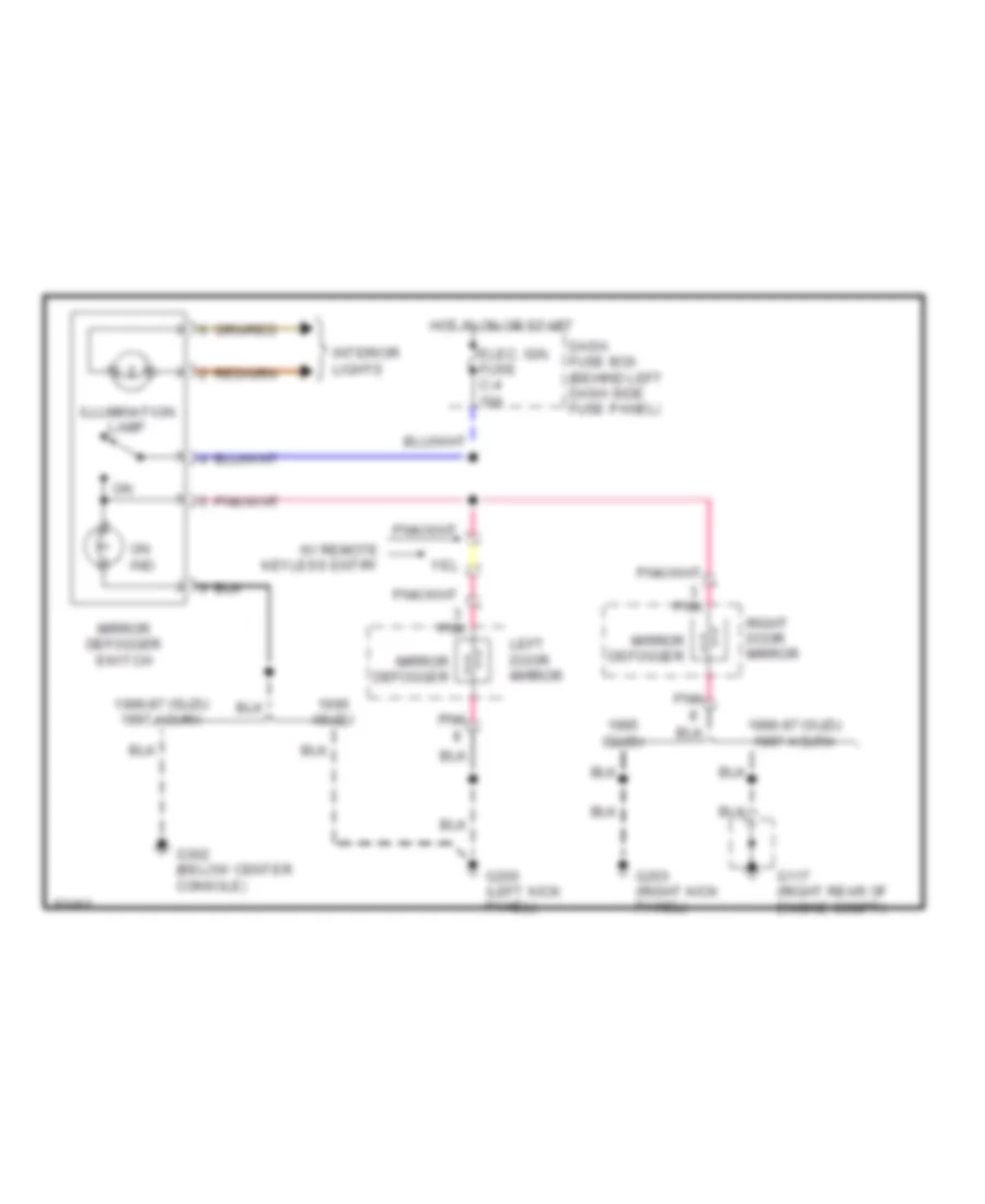
Heated Mirrors Wiring Diagram for Isuzu Trooper Limited 1995
 https://portal-diagnostov.com/license.html
Automotive Electricians Portal FZCO
Automotive Electricians Portal FZCO
https://portal-diagnostov.com/license.html
https://portal-diagnostov.com/license.html
Automotive Electricians Portal FZCO
Automotive Electricians Portal FZCOList of elements for Heated Mirrors Wiring Diagram for Isuzu Trooper Limited 1995:
- 1996-97 isuzu 1997 acura
- Dash fuse box (behind left dash side fuse panel)
- Elec. ign. fuse c-4 10a
- G117 (right rear of engine compt)
- G200 (left kick panel)
- G203 (right kick panel)
- G302 (below center console)
- Hot in on or start
- Illumination lamp
- Interior lights
- Isuzu
- Left door mirror
- Mirror defogger
- Mirror defogger switch
- On ind
- Pnk
- Right door mirror
- W/ remote keyless entry
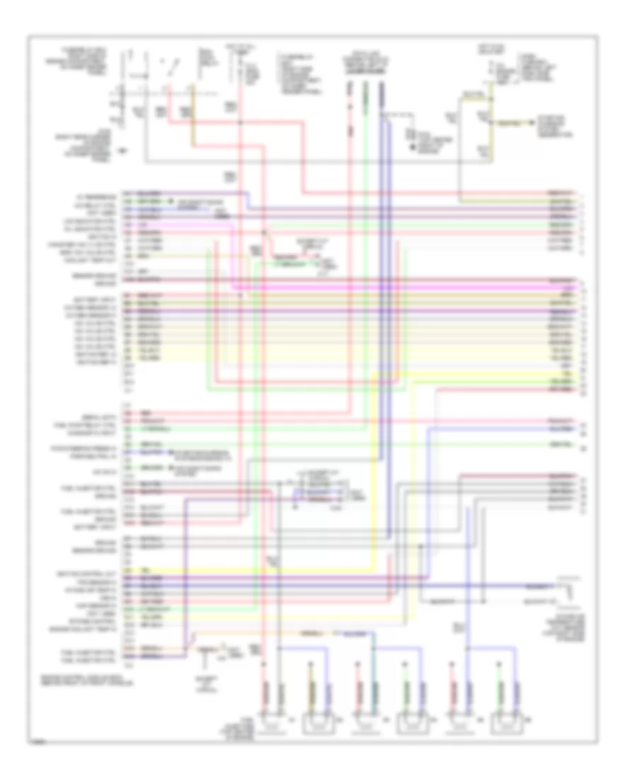
ENGINE PERFORMANCE
3.2L
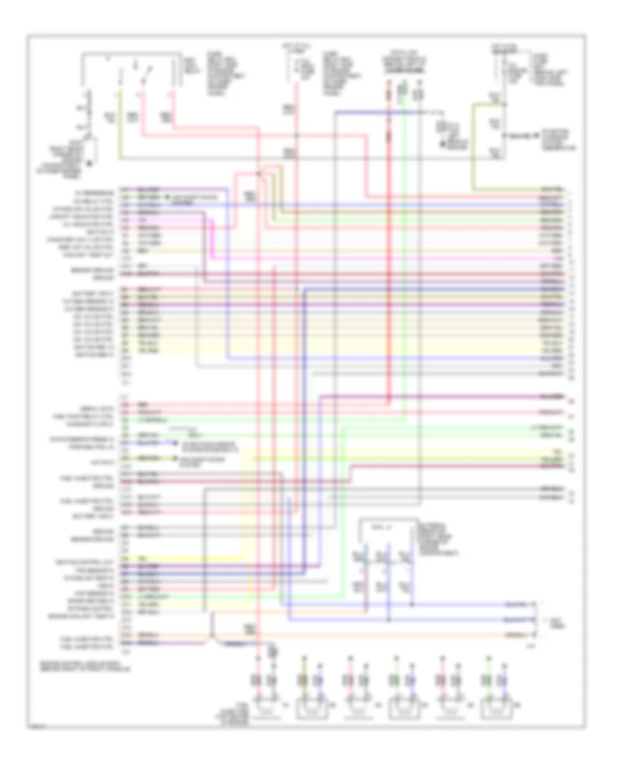
3.2L DOHC, Engine Performance Wiring Diagrams (1 of 4) for Isuzu Trooper Limited 1995
 https://portal-diagnostov.com/license.html
Automotive Electricians Portal FZCO
Automotive Electricians Portal FZCO
https://portal-diagnostov.com/license.html
https://portal-diagnostov.com/license.html
Automotive Electricians Portal FZCO
Automotive Electricians Portal FZCOList of elements for 3.2L DOHC, Engine Performance Wiring Diagrams (1 of 4) for Isuzu Trooper Limited 1995:
- (diode box a)
- (not used)
- 5v reference
- A/c on in
- A/c relay ctrl
- A/t only
- A10
- A11
- A12
- Air conditioning system
- B10
- B11
- B12
- Battery input
- Bypass control
- C-1
- C-2
- C-8 engine fuse 15a
- C10
- C11
- C12
- C13
- C14
- C15
- C16
- Canister vac vlve ctrl
- Coolant temp out
- D10
- D11
- D12
- D13
- D14
- D15
- D16
- Dash fuse box (behind left dash side trim panel)
- Data link connector (dlc) (behind left i/p lower cover)
- Diagnostic input
- Ecm main relay
- Egr vac valve ctrl
- Engine control module (ecm) (behind front of front console)
- Engine coolant temp in
- External resistor (right rear corner of engine compartment)
- Fl3 (ecm) fuse 30a
- Fuel injector ctrl
- Fuel injectors (top center of engine)
- Fuel pump relay ctrl
- Fuse/ relay box (right side of engine compartment, on inner fender panel)
- G105 (right rear corner of engine compartment, on inner fender panel)
- G114 (top left rear of engine)
- Ground
- H-4
- Hot at all times
- Hot in on or start
- Iac valve ctrl
- Ignition control out
- Ignition in
- Ignition ref hi
- Ignition ref lo
- Intake air temp in
- Intake air valve ctrl
- Map sensor in
- Mil indicator ctrl
- Oxygen sensor hi
- Oxygen sensor lo
- Park/neutral in
- Pwr steering press in
- Red
- Sensor ground
- Serial data
- Spark retard in
- Starting/ charging system (generator)
- Starting/charging system
- Tps sensor in
- Upshift indicator ctrl
- Vss in
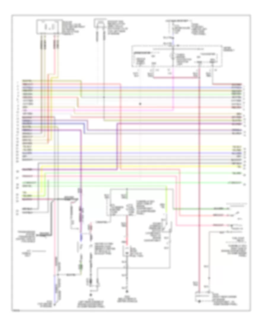
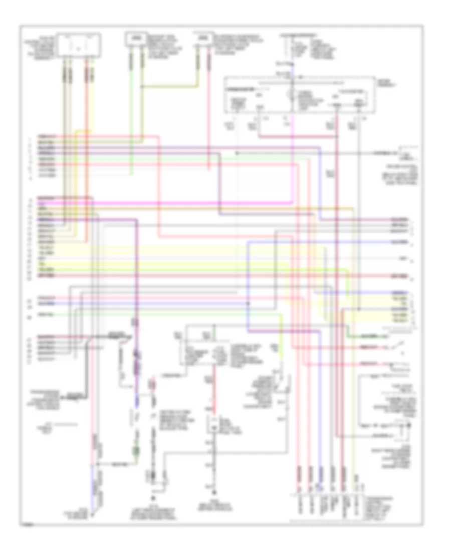
3.2L DOHC, Engine Performance Wiring Diagrams (2 of 4) for Isuzu Trooper Limited 1995
 https://portal-diagnostov.com/license.html
Automotive Electricians Portal FZCO
Automotive Electricians Portal FZCO
https://portal-diagnostov.com/license.html
https://portal-diagnostov.com/license.html
Automotive Electricians Portal FZCO
Automotive Electricians Portal FZCOList of elements for 3.2L DOHC, Engine Performance Wiring Diagrams (2 of 4) for Isuzu Trooper Limited 1995:
- "check engine" malfunction indicator lamp
- (a/t)
- (m/t)
- A/t models only
- Braided wire
- C-10 meter gauge fuse 10a
- Dash fuse box (behind left dash side trim panel)
- Exhaust gas recirculation (egr) vacuum switching valve (top left rear of engine)
- F-10 fuel pump fuse 15a
- F-2 o2 sensor heater fuse 10a
- Fuel pump (in top of fuel tank)
- Fuel pump relay
- Fuse/relay box (right side of engine compartment, on inner fender panel)
- Fuse/relay box (right side of engine compartment, on inner fender panel)
- G105 (right rear corner of engine compartment , on inner fender panel)
- G116 (left rear corner of engine compartment, on inner fender panel)
- G134 (top center of engine)
- G302 (below rear of center console)
- Gnd
- Heated oxygen sensor (ho2s) (beneath center of vehicle, in exhaust pipe)
- Hot in on or start
- I-10
- I-9
- Idle air control valve (top center front of engine, on air intake asembly)
- Ign
- Meter assembly
- Power steering pressure switch (lower right front of engine compartment)
- Red
- Rpm input
- Speedometer
- Tachometer
- Transmissions system (transmission control module (tcm) shield
- Vehicle speed output
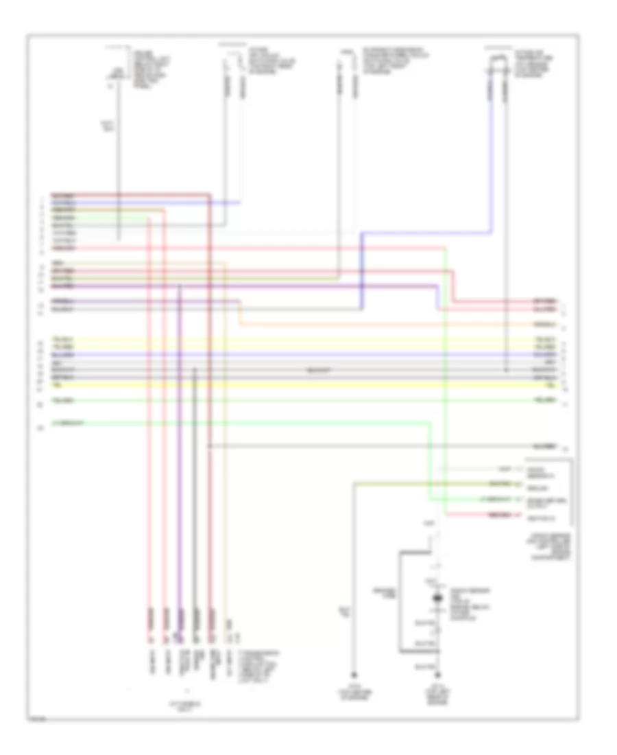
3.2L DOHC, Engine Performance Wiring Diagrams (3 of 4) for Isuzu Trooper Limited 1995
 https://portal-diagnostov.com/license.html
Automotive Electricians Portal FZCO
Automotive Electricians Portal FZCO
https://portal-diagnostov.com/license.html
https://portal-diagnostov.com/license.html
Automotive Electricians Portal FZCO
Automotive Electricians Portal FZCOList of elements for 3.2L DOHC, Engine Performance Wiring Diagrams (3 of 4) for Isuzu Trooper Limited 1995:
- (a/t models only)
- A7 ign input
- A8 ign input
- Braided wire
- C-90
- C-91
- C5 throttle posit in
- C6 sensor gnd
- Cruise control unit (below right side of i/p, above dash side trim panel)
- D12 engine rpm input
- D14 ect input
- Evaporative emission canister purge vacuum switching valve (top left front of engine)
- G114 (top left rear of engine)
- G134 (top center of engine)
- Ground
- Ignition in
- Intake air temperature (iat) sensor (top center of engine)
- Intake air vacuum switching valve (top right rear of engine)
- Knock sensor (ks) (top of engine, below intake manifold)
- Knock sensor (ks) controller (left side of engine compartment)
- Knock sensor in
- Spark retard output
- Transmission control module (tcm) (below left side of i/p) (a/t only)
- Vss input
3.2L DOHC, Engine Performance Wiring Diagrams (4 of 4) for Isuzu Trooper Limited 1995
 https://portal-diagnostov.com/license.html
Automotive Electricians Portal FZCO
Automotive Electricians Portal FZCO
https://portal-diagnostov.com/license.html
https://portal-diagnostov.com/license.html
Automotive Electricians Portal FZCO
Automotive Electricians Portal FZCOList of elements for 3.2L DOHC, Engine Performance Wiring Diagrams (4 of 4) for Isuzu Trooper Limited 1995:
- "u/s" indicator lamp
- (firing order: (1-2-3-4-5-6)
- Abs
- Anti-lock brakes system
- C-4 elec. ign fuse 10a
- C-9 ign coil fuse 15a
- Clutch switch (behind i/p, top of clutch pedal support)
- Combination switch
- Crank- shaft position sensor shield
- Crankshaft position sensor (lower right side of engine, above oil pan)
- Crnk pos sens
- Cruise control system
- Ctrl in bypass
- Ctrl in ignition
- Dash fuse box (behind left dash side trim panel)
- E-18
- E-21
- E-22
- Electronic ignition (ei) (top center rear of engine)
- Engine coolant temperature (ect) sensor (right rear of engine)
- F-12 tail fuse 15a
- Fuse/relay box (right side of engine compartment, on inner fender panel)
- G105 (right rear corner of engine compartment, on inner fender panel)
- G115 (top left rear of engine)
- G202 (behind top of left dash side trim panel)
- Ground
- Head
- Head- lights
- Hi out ign ref
- Hot at all times
- Hot in on or start
- I-9
- Ignition coils
- Interior lights system (dash & console lights)
- Lighting switch
- Lo out ign ref
- M/t only
- Manifold absolute pressure (map) sensor (top left front of engine)
- Meter assembly
- Nca
- Off
- Park
- Power ignition
- Rpm out
- Rwal
- Sens crnk pos
- Shield ground
- Solid state
- Spark plug wires
- Tail light relay
- Throttle position (tp) sensor (top center front of engine, on air intake assembly)
- Transmission switch 1-2 (closed with transmission in 1st or 2nd gear) (on left side of transmission)
- Transmission switch 3-4 (closed with transmission in 3rd or 4th gear) (on top of transmission)
- Up-shift resistor
- Upshift relay-1
- Upshift relay-2
3.2L SOHC, Engine Performance Wiring Diagrams (1 of 3) for Isuzu Trooper Limited 1995
 https://portal-diagnostov.com/license.html
Automotive Electricians Portal FZCO
Automotive Electricians Portal FZCO
https://portal-diagnostov.com/license.html
https://portal-diagnostov.com/license.html
Automotive Electricians Portal FZCO
Automotive Electricians Portal FZCOList of elements for 3.2L SOHC, Engine Performance Wiring Diagrams (1 of 3) for Isuzu Trooper Limited 1995:
- (diode box a)
- (not used)
- (not used) h-6
- 5v reference
- A/c on in
- A/c relay ctrl
- A10
- A11
- A12
- Air conditioning system
- B10
- B11
- B12
- Battery input
- Bypass control
- C-1
- C-17
- C-2
- C-40
- C-8 engine fuse 15a
- C10
- C11
- C12
- C13
- C14
- C15
- C16
- Canister vac vlve ctrl
- Coolant temp out
- D10
- D11
- D12
- D13
- D14
- D15
- D16
- Dash fuse box (behind left dash side trim panel)
- Data link connector (dlc) (behind left i/p lower cover)
- Diagnostic input
- Ecm main relay
- Egr vac valve ctrl
- Engine control module (ecm) (behind front of front console)
- Engine coolant temp in
- Except m/t w/rwal
- Fl-3 (ecm) fuse 30a
- Fuel injector ctrl
- Fuel injectors (top center of engine)
- Fuel pump relay ctrl
- Fuse/relay box (right side of engine compartment, on inner fender panel)
- G105 (right rear corner of engine compartment, on inner fender panel)
- G134 (top center front of engine)
- Ground
- Hot at all times
- Hot in on or start
- Iac valve ctrl
- Ignition control out
- Ignition in
- Ignition ref hi
- Ignition ref lo
- Intake air temp in
- Intake air temperature (iat) sensor (top right side of engine)
- Map sensor in
- Mil indicator ctrl
- Oxygen sensor hi
- Oxygen sensor lo
- Park/neutral in
- Pwr steering press in
- Red
- Sensor ground
- Serial data
- Starting charging system (generator)
- Starting/charging system
- Tps sensor in
- U/s indicator ctrl
- Vss in
3.2L SOHC, Engine Performance Wiring Diagrams (2 of 3) for Isuzu Trooper Limited 1995
 https://portal-diagnostov.com/license.html
Automotive Electricians Portal FZCO
Automotive Electricians Portal FZCO
https://portal-diagnostov.com/license.html
https://portal-diagnostov.com/license.html
Automotive Electricians Portal FZCO
Automotive Electricians Portal FZCOList of elements for 3.2L SOHC, Engine Performance Wiring Diagrams (2 of 3) for Isuzu Trooper Limited 1995:
- "check engine" malfunction indicator lamp
- (a/t)
- (m/t)
- A/t models only
- A7 ign input
- Braided wire
- C-10 meter fuse 10a
- C-90 ign input
- C-91
- C5 throttle
- C6 sensor
- Cruise control unit (below right side of i/p, above dash side trim panel)
- D12 engine rpm
- D14 ect input
- Dash fuse box (below left dash side trim panel)
- Evaporative emission canister purge vacuum switching valve (top left rear of engine)
- Exhaust gas recirculation (egr) vacuum switching valve (top left rear of engine)
- F-10 fuel pump fuse 15a
- F-2 o2 sensor heater fuse 10a
- Fuel pump (in top of fuel tank)
- Fuel pump relay
- Fuse/relay box (right side of engine compartment, on inner fender panel)
- Fuse/relay box (right side of engine compartment, on inner fender panel)
- G105 (right rear corner of engine compartment, on inner fender panel)
- G116 (left rear corner of engine compartment, on inner fender panel)
- G134 (top center of engine)
- G302 (below rear of center console)
- Gnd
- Heated oxygen sensor (ho2s) (beneath center of vehicle, in exhaust pipe)
- Hot in on or start
- I-10
- I-9
- Idle air control valve (top center of engine, on air intake assembly)
- Ign
- Input
- Meter assembly
- Posit in
- Power steering pressure switch (lower right front of engine compartment)
- Red
- Rpm input
- Speedometer
- Tachometer
- Transmission control module (tcm) (below left side of i/p) (a/t only)
- Transmissions system (transmission control module (tcm) shield
- Vehicle speed output
- Vss input
3.2L SOHC, Engine Performance Wiring Diagrams (3 of 3) for Isuzu Trooper Limited 1995
 https://portal-diagnostov.com/license.html
Automotive Electricians Portal FZCO
Automotive Electricians Portal FZCO
https://portal-diagnostov.com/license.html
https://portal-diagnostov.com/license.html
Automotive Electricians Portal FZCO
Automotive Electricians Portal FZCOList of elements for 3.2L SOHC, Engine Performance Wiring Diagrams (3 of 3) for Isuzu Trooper Limited 1995:
- "u/s" indicator lamp
- (firing order: 1-2-3-4-5-6)
- Abs
- Anti-lock brakes system
- Bypass ctrl in
- C-4 elec. ign fuse 10a
- C-9 ign coil fuse 15a
- Clutch switch (behind i/p, top of clutch pedal support)
- Combination switch
- Crank- shaft position sensor shield
- Crankshaft position sensor (lower right side of engine, above oil pan)
- Crnk pos sens
- Cruise control system
- Dash fuse box (behind left dash side trim panel)
- E-18
- E-21
- E-22
- Electronic ignition (ei) (center front of engine)
- Engine coolant temperature (ect) sensor (right rear of engine)
- F-12 tail fuse 15a
- Fuse/relay box (right side of engine compartment, on inner fender panel)
- G105 (right rear corner of engine compartment, on inner fender panel)
- G134 (top center front of engine)
- G202 (behind top of left dash side trim panel)
- Ground
- Ground shield
- Head
- Head- lights
- Hot at all times
- Hot in on or start
- I-9
- Ign ref hi out
- Ign ref lo out
- Ignition coils
- Ignition ctrl in
- Ignition power
- Interior lights system (dash & console lights)
- Lighting switch
- M/t only
- Manifold absolute pressure (map) sensor (top right side of engine)
- Meter assembly
- Nca
- Off
- Park
- Rpm out
- Rwal
- Sens crnk pos
- Solid state
- Spark plug wires
- Tail light relay
- Throttle position (tp) sensor (top center of engine, on air intake assembly)
- Transmission switch 1-2 (closed with transmission in 1st or 2nd gear) (on left side of transmission)
- Transmission switch 3-4 (closed with transmission in 3rd or 4th gear) (on top of transmission)
- Up-shift resistor
- Upshift relay-1
- Upshift relay-2
EXTERIOR LIGHTS
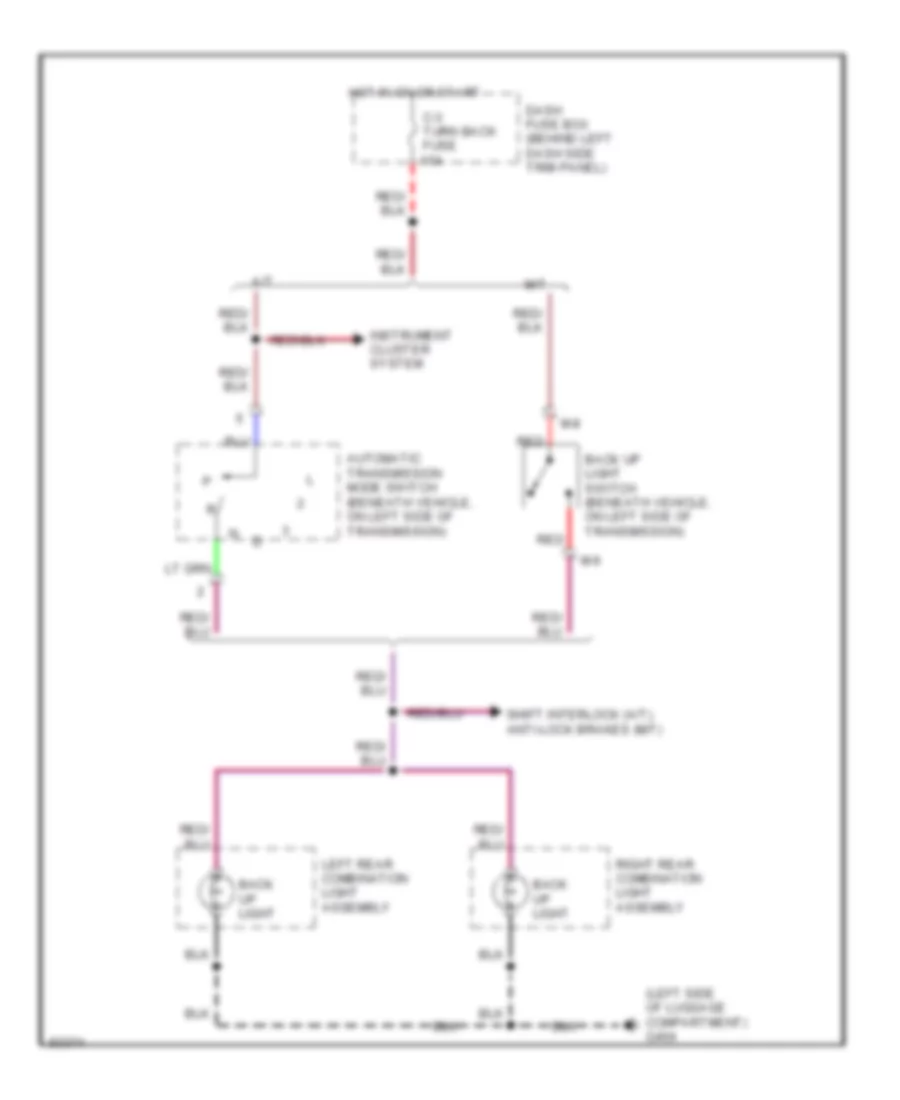
Back-up Lamps Wiring Diagram for Isuzu Trooper Limited 1995
 https://portal-diagnostov.com/license.html
Automotive Electricians Portal FZCO
Automotive Electricians Portal FZCO
https://portal-diagnostov.com/license.html
https://portal-diagnostov.com/license.html
Automotive Electricians Portal FZCO
Automotive Electricians Portal FZCOList of elements for Back-up Lamps Wiring Diagram for Isuzu Trooper Limited 1995:
- (left side of luggage compartment) g404
- 15a
- A/t
- Automatic transmission mode switch (beneath vehicle, on left side of transmission)
- Back up light
- Back up light switch (beneath vehicle, on left side of transmission)
- C-3 turn back fuse
- Dash fuse box (behind left dash side trim panel)
- Hot in on or start
- Instrument cluster system
- Left rear combination light assembly
- M-8
- M-9
- M/t
- Red
- Right rear combination light assembly
- Shift interlock (a/t), anti-lock brakes (m/t)
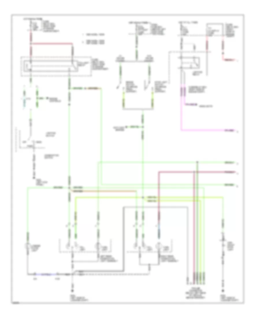
Exterior Lamps Wiring Diagram (1 of 2) for Isuzu Trooper Limited 1995
 https://portal-diagnostov.com/license.html
Automotive Electricians Portal FZCO
Automotive Electricians Portal FZCO
https://portal-diagnostov.com/license.html
https://portal-diagnostov.com/license.html
Automotive Electricians Portal FZCO
Automotive Electricians Portal FZCOList of elements for Exterior Lamps Wiring Diagram (1 of 2) for Isuzu Trooper Limited 1995:
- 1995 model year
- 1996 model year 1997 model year
- Anti-lock brakes
- Brake switch (on brake pedal support)
- C-14 stop a/t cont fuse 15a
- Combination switch
- Dash fuse box (behind left dash side trim panel)
- Engine controls
- F-12 tail fuse 15a
- F-4 h/lamp-lh fuse 15a
- Fl-1 main fuse 80a
- Fuse/ relay box (right side of engine compartment)
- Fuse/ relay box (right side of engine compt)
- Fuse/relay box (right side of engine compt)
- G-8
- G200 (left kick panel)
- G400 (left side of luggage compt)
- G404 (left side of luggage compt)
- H-12
- H-39
- Head
- Headlights
- High mount stop light
- Hot at all times
- Left rear combination light assembly
- License plate light
- Lighting relay
- Lighting switch
- Nca
- Off
- Park
- Right rear combination light assembly
- Stop light switch (on brake pedal support)
- Tail- light
- Taillight relay
- Trailer connector (below left rear of vehicle, behind grommet)
- Turn light
- W/ cruise control
- W/o cruise control
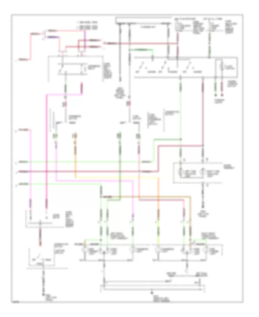
Exterior Lamps Wiring Diagram (2 of 2) for Isuzu Trooper Limited 1995
 https://portal-diagnostov.com/license.html
Automotive Electricians Portal FZCO
Automotive Electricians Portal FZCO
https://portal-diagnostov.com/license.html
https://portal-diagnostov.com/license.html
Automotive Electricians Portal FZCO
Automotive Electricians Portal FZCOList of elements for Exterior Lamps Wiring Diagram (2 of 2) for Isuzu Trooper Limited 1995:
- (right side of engine compt)
- 1995 model year
- 1995-1996 izuzu
- 1996 model year
- 1997 isuzu 1997 acura
- 1997 model year
- C-3 turn back fuse 15a
- Combination switch
- Cornering light
- Cornering relay
- Cornering switch
- Dash fuse box (behind left dash side trim panel)
- Diode box b
- F-3 hazard fuse 15a
- Flasher unit
- Fuse/ relay box
- Fuse/ relay box (right side of engine compt)
- G104 (rear of left front fender)
- G200 (left kick panel)
- G202 (behind lower left dash panel)
- Ground
- Hazard
- Hazard warning switch
- Head
- Hot at all times
- Hot in on or start
- I-10
- I-9
- Ignition
- Illum- ination
- Interior lights
- Left
- Left front combination light assembly
- Left turn indicator light
- Lighting switch
- Meter assembly
- Off
- Output
- Park
- Park/ turn light
- Red
- Right
- Right front combination light assembly
- Right turn indicator light
- Side marker light
- Turn signal/ cornering light switch
- Turn switch
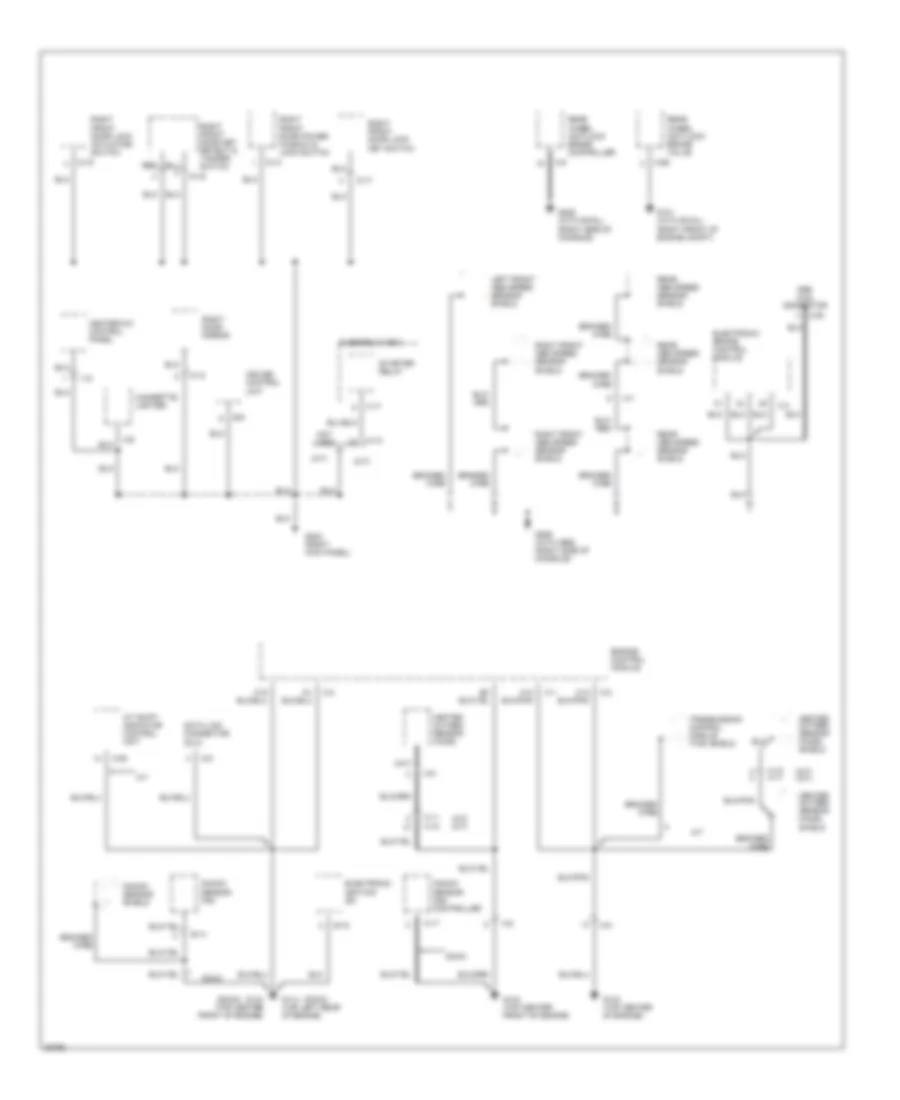
GROUND DISTRIBUTION
Ground Distribution Wiring Diagram (1 of 4) for Isuzu Trooper Limited 1995
 https://portal-diagnostov.com/license.html
Automotive Electricians Portal FZCO
Automotive Electricians Portal FZCO
https://portal-diagnostov.com/license.html
https://portal-diagnostov.com/license.html
Automotive Electricians Portal FZCO
Automotive Electricians Portal FZCOList of elements for Ground Distribution Wiring Diagram (1 of 4) for Isuzu Trooper Limited 1995:
- (a/t)
- (m/t)
- (m/t) w/ abs
- 4wd switch
- Abs hydraulic unit
- Battery
- Brake fluid level switch
- C-15
- C-22
- C-23
- C-24
- C-26
- C-29
- C-30
- C-31
- C-34
- C-35
- C-37
- C-38
- C-44
- C-91
- C-92
- Cornering light
- Cruise control pump/ actuator
- Cruise main relay
- F-5
- Front park/ turn signal light
- Front side marker light
- Fuel pump relay
- Fuel tank unit
- Fuse/ relay box
- G104 (rear of left front fender)
- G110 (left side of engine compt.)
- G112 (top of oil pan)
- G115 (right side of engine compt.)
- G117 (right rear of engine compt.)
- G119 (lower right front of engine compt.)
- G120 (lower right side of engine compt.)
- G125 (right side of engine compartment, on rear of battery tray)
- G205 (behind right side of lower cluster assembly)
- H-10
- H-11
- Headlight wiper timer unit
- Heated oxygen sensor
- I-10
- I-15
- I-9
- Left
- Left fog light
- Left front combination light assembly
- Left head- light wiper motor
- Left valve cover
- M-12
- M-5
- Meter assembly
- Pcm main relay
- Power steering pressure switch
- Radio
- Right cornering light
- Right fog light
- Right front combination light assembly
- Right front park/ turn signal light
- Right front side marker light
- Right head- light wiper motor
- Right valve cover
- Tech-1 connector
- Transmission control module
- Upshift relay-1
- Upshift relay-2
- Windshield intermittent wiper relay
- Windshield washer motor
- Windshield wiper motor
- X-11
- X-12
- X-13
- X-16
- X-20
- X-21
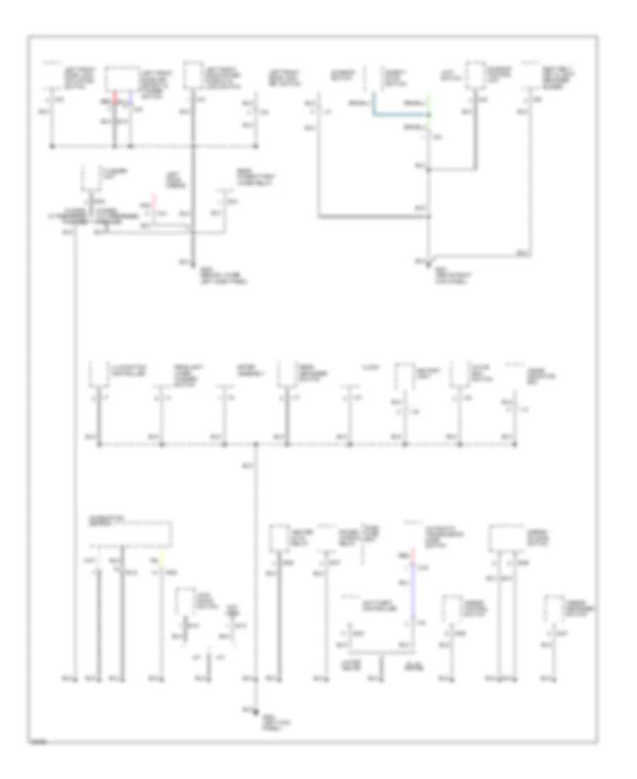
Ground Distribution Wiring Diagram (2 of 4) for Isuzu Trooper Limited 1995
 https://portal-diagnostov.com/license.html
Automotive Electricians Portal FZCO
Automotive Electricians Portal FZCO
https://portal-diagnostov.com/license.html
https://portal-diagnostov.com/license.html
Automotive Electricians Portal FZCO
Automotive Electricians Portal FZCOList of elements for Ground Distribution Wiring Diagram (2 of 4) for Isuzu Trooper Limited 1995:
- (a/t)
- (a/t) (m/t)
- (dohc)
- (m/t)
- (m/t) (a/t)
- (sohc)
- A/t
- A/t shift indicator control unit
- Abs aldl connector
- B-9
- Braided wire
- C-1
- C-17
- C-2
- C-4
- C-5
- C-9
- C-93
- C-94
- C-95
- Cigarette lighter
- Cruise control unit
- D-12
- D-14
- D-16
- D-17
- D-19
- Data link connector (dlc)
- Dohc
- E-14
- E-18
- Electronic brake control module
- Electronic ignition (ei)
- Engine control module
- Fuse/relay box
- G101 (with rwal) (right front of engine compt)
- G114 (top left rear of engine)
- G133 (top center of engine)
- G134 (top center front of engine)
- G203 (right kick panel)
- G206 (with abs) (right side of console)
- G206 (with rwal) (right side of console)
- H-10 h-11
- H-11 h-10
- H-12
- H-5
- H-7
- Heated oxygen sensor (ho2s)
- Heated oxygen sensor (ho2s) shield
- Heater-a/c control panel
- I-18
- I-22
- Knock sensor (ks)
- Knock sensor (ks) controller
- Knock sensor shield
- Left front abs speed sensor shield
- M-5
- Not used
- Rear abs speed sensor shield
- Rear wheel anti-lock brake controller
- Rear wheel anti-lock brake valve
- Red
- Right door mirror
- Right front abs speed sensor shield
- Right front door key detect & tamper switch
- Right front door lock actuator/ switch
- Right front door lock key switch
- Right front door power window & lock switch
- Starter relay
- Transmission control module (tcm) shield
- X-17
Ground Distribution Wiring Diagram (3 of 4) for Isuzu Trooper Limited 1995
 https://portal-diagnostov.com/license.html
Automotive Electricians Portal FZCO
Automotive Electricians Portal FZCO
https://portal-diagnostov.com/license.html
https://portal-diagnostov.com/license.html
Automotive Electricians Portal FZCO
Automotive Electricians Portal FZCOList of elements for Ground Distribution Wiring Diagram (3 of 4) for Isuzu Trooper Limited 1995:
- A/t
- Anti-theft controller
- Ashtray light
- Automatic transmission mode switch
- B-10
- B-12
- B-20
- B-21
- B-36
- B-37
- B-52
- B-53
- B-55
- B-56
- B-57
- B-6
- C-43
- Clock
- Combination switch
- D-3
- D-5
- D-6
- D-8
- D-9
- Dash fuse box
- Flasher unit
- G200 (left kick panel)
- G201 (above right kick panel)
- G202 (behind lower left dash panel)
- Glove box switch
- H-8
- Headlight wiper washer switch
- Heater & a/c relay
- I-13
- I-17
- I-19
- I-27
- I-38
- I-4
- I-7
- I-9
- Illumination controller
- Inside indicator box
- Kick- down switch
- L-2
- Left door mirror
- Left front door key detect & tamper switch
- Left front door lock actuator/ switch
- Left front door lock key switch
- Left front door power window & lock switch
- Limit switch
- Limited and rs
- M/t
- Meter assembly
- Mirror control switch
- Mirror defogger switch
- Mirror folding switch
- Not used
- Pnk
- Power window relay
- Rear defogger switch
- Rear intermittent wiper relay
- Red
- S model w/ preferred package
- S model w/o preferred package
- S, ls and se
- S-2
- S-5
- Safety stop switch
- Seat belt, key & light reminder buzzer
- Sunroof control unit
- Sunroof switch
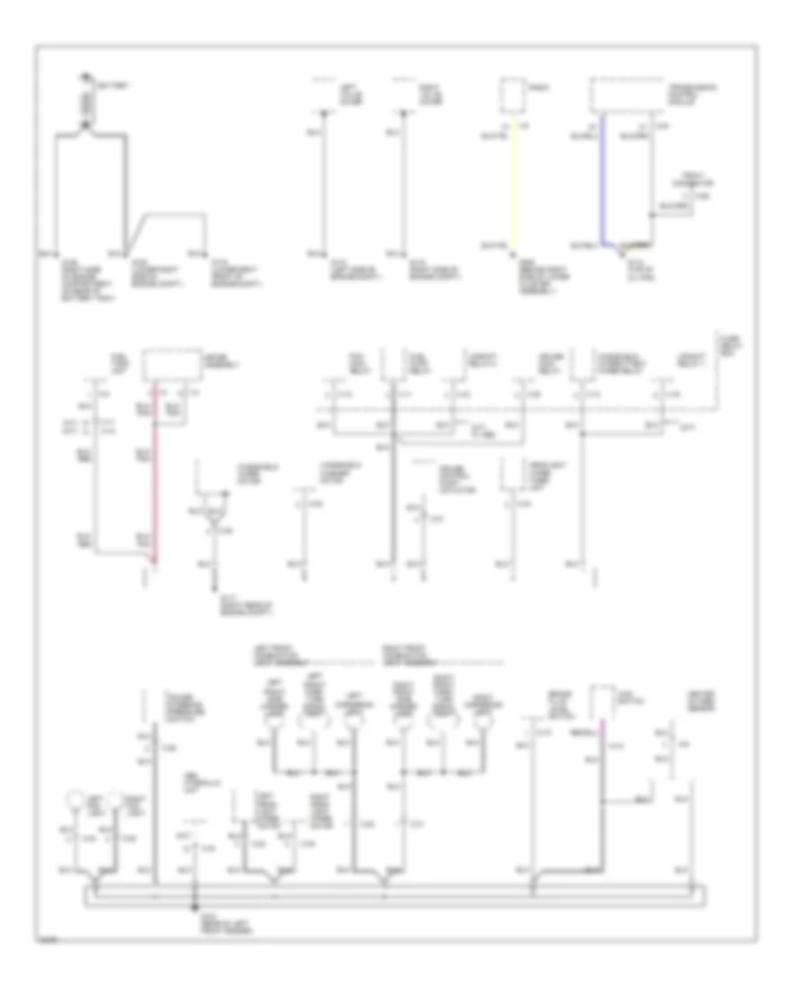
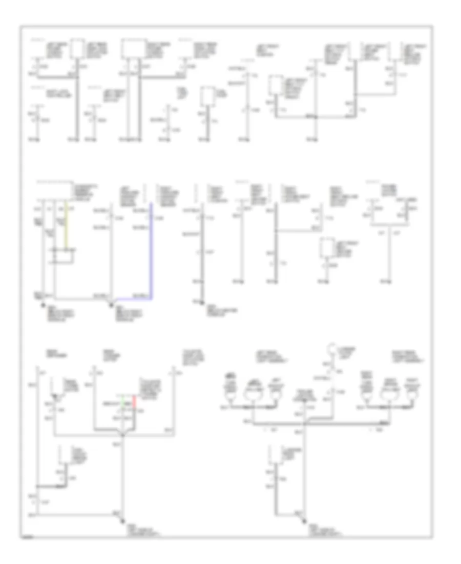
Ground Distribution Wiring Diagram (4 of 4) for Isuzu Trooper Limited 1995
 https://portal-diagnostov.com/license.html
Automotive Electricians Portal FZCO
Automotive Electricians Portal FZCO
https://portal-diagnostov.com/license.html
https://portal-diagnostov.com/license.html
Automotive Electricians Portal FZCO
Automotive Electricians Portal FZCOList of elements for Ground Distribution Wiring Diagram (4 of 4) for Isuzu Trooper Limited 1995:
- (not used)
- A/t
- A12
- B-24
- B-29
- B-30
- B-31
- B-32
- Backup light
- C-48
- C-49
- D-21
- D-22
- D-26
- D-27
- Diagnostic energy reserve module
- F-4
- F-5
- Fuel pump
- Fuel tank unit
- G-2
- G-4
- G-5
- G-6
- G-7
- G-8
- G-9
- G300 (below right side of front console)
- G301 (below right side of front console)
- G302 (below center console)
- G400 (left side of luggage compt.)
- G404 (left side of luggage compt.)
- H-33
- H-37
- H-39
- H-44
- H-46
- H-47
- High mount brake light
- Left
- Left brake/
- Left forward discrimi- nating sensor
- Left front power seat switch
- Left front seat belt switch
- Left front seat cushion
- Left front seat heater switch
- Left front seat recline motor & switch
- Left front seat tilt motor & switch (front)
- Left front seat tilt motor & switch (rear)
- Left rear
- Left rear combination light assembly
- Left rear door lock actuator/ switch
- Left rear power window switch
- License plate light
- Luggage room light
- M/t
- Power/ winter switch
- R-6
- R-7
- R-9
- Rear defogger
- Rear washer motor
- Rear wiper motor
- Red
- Right
- Right brake/
- Right forward discrimi- nating sensor
- Right front power seat switch
- Right front seat cushion
- Right front seat heater switch
- Right front seat recline motor & switch
- Right rear
- Right rear combination light assembly
- Right rear door lock actuator/ switch
- Right rear power window switch
- Shift lock controller
- T-10
- T-11
- T-12
- T-2
- T-3
- T-5
- T-8
- Tailgate door key detect & tamper switch
- Tailgate door lock actuator/ switch
- Taillight
- Trailer lighting connector
- Turn signal light
- U-4
- U-5
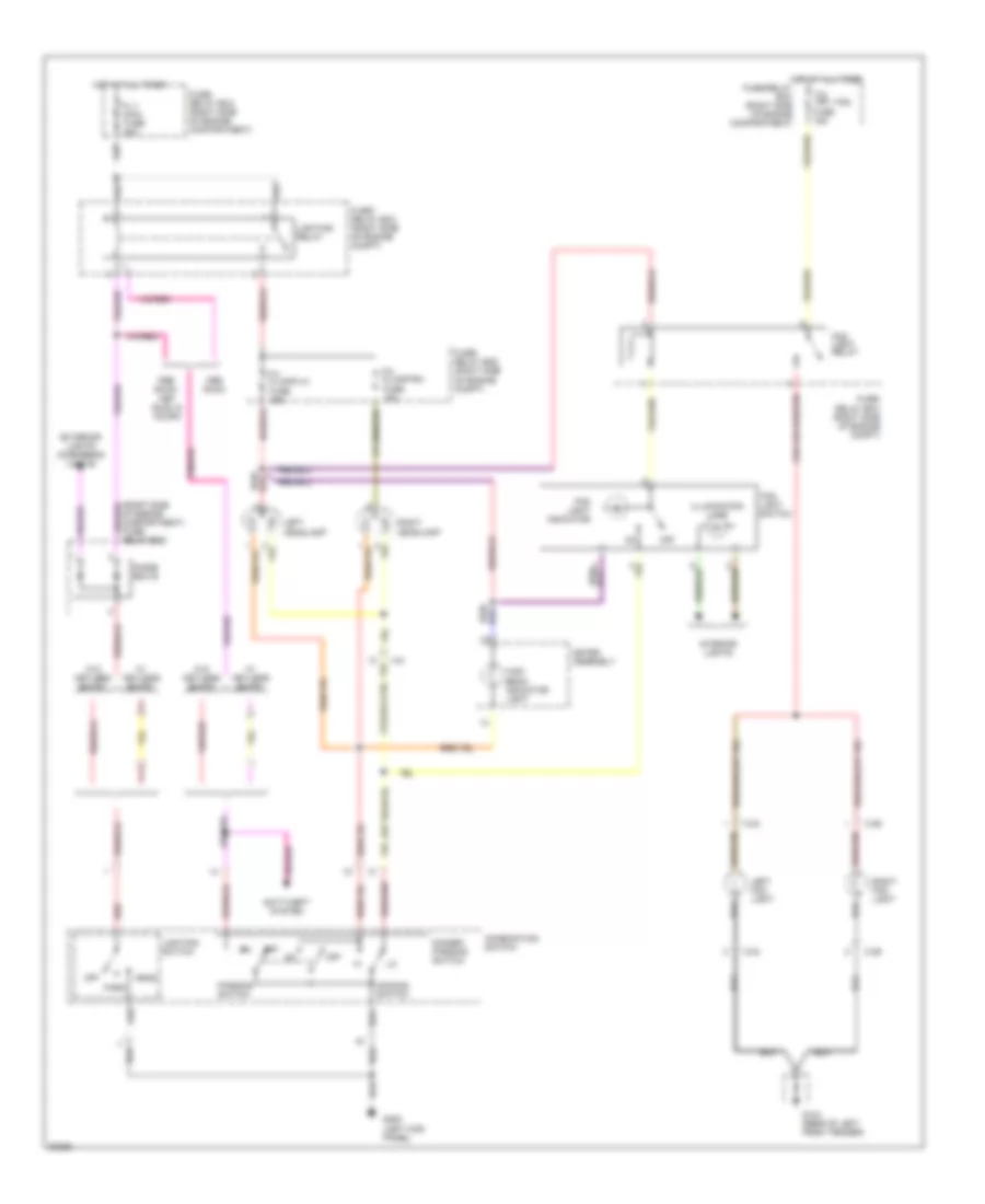
HEADLIGHTS
Headlamps/Fog Lamps Wiring Diagram for Isuzu Trooper Limited 1995
 https://portal-diagnostov.com/license.html
Automotive Electricians Portal FZCO
Automotive Electricians Portal FZCO
https://portal-diagnostov.com/license.html
https://portal-diagnostov.com/license.html
Automotive Electricians Portal FZCO
Automotive Electricians Portal FZCOList of elements for Headlamps/Fog Lamps Wiring Diagram for Isuzu Trooper Limited 1995:
- (right side of engine compartment) fuse/ relay box
- Anti-theft system
- C-24
- C-29
- Combination switch
- Dimmer/ passing switch
- Dimming switch
- Diode box b
- Exterior lights (cornering lights)
- F-4 h/lamp-lh
- F-5 h/lamp-rh
- F-8 frt. fog fuse 15a
- Fl-1 main fuse 80a
- Fog light indicator
- Fog light relay
- Fog light switch
- Fuse 15a
- Fuse/ relay box (right side of engine compartment)
- Fuse/ relay box (right side of engine compt)
- G104 (rear of left front fender)
- G200 (left kick panel)
- H-8
- Head
- High beam indicator light
- Hot at all times
- Hot at all times fuse/relay box (right side of engine compartment)
- Illumination lamp
- Interior lights
- Isuzu
- Isuzu/ isuzu & acura
- Left fog light
- Left headlamp
- Lighting relay
- Lighting switch
- Meter assembly
- Off
- Park
- Passing switch
- Red
- Right fog light
- Right headlamp
- W/ keyless entry
- W/o keyless entry
Headlight Wiring Diagram for Isuzu Trooper Limited 1995
 https://portal-diagnostov.com/license.html
Automotive Electricians Portal FZCO
Automotive Electricians Portal FZCO
https://portal-diagnostov.com/license.html
https://portal-diagnostov.com/license.html
Automotive Electricians Portal FZCO
Automotive Electricians Portal FZCOList of elements for Headlight Wiring Diagram for Isuzu Trooper Limited 1995:
- (right side of engine compartment) fuse/ relay box
- Anti-theft system
- C-24
- C-29
- Combination switch
- Dimmer/ passing switch
- Dimming switch
- Diode box b
- Exterior lights (cornering lights)
- F-4 h/lamp-lh
- F-5 h/lamp-rh
- F-8 frt. fog fuse 15a
- Fl-1 main fuse 80a
- Fog light indicator
- Fog light relay
- Fog light switch
- Fuse 15a
- Fuse/ relay box (right side of engine compartment)
- Fuse/ relay box (right side of engine compt)
- G104 (rear of left front fender)
- G200 (left kick panel)
- H-8
- Head
- High beam indicator light
- Hot at all times
- Hot at all times fuse/relay box (right side of engine compartment)
- Illumination lamp
- Interior lights
- Isuzu
- Isuzu/ isuzu & acura
- Left fog light
- Left headlamp
- Lighting relay
- Lighting switch
- Meter assembly
- Off
- Park
- Passing switch
- Red
- Right fog light
- Right headlamp
- W/ keyless entry
- W/o keyless entry
HORN
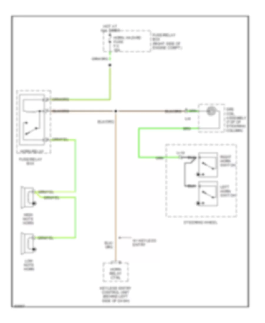
Horn Wiring Diagram for Isuzu Trooper Limited 1995
 https://portal-diagnostov.com/license.html
Automotive Electricians Portal FZCO
Automotive Electricians Portal FZCO
https://portal-diagnostov.com/license.html
https://portal-diagnostov.com/license.html
Automotive Electricians Portal FZCO
Automotive Electricians Portal FZCOList of elements for Horn Wiring Diagram for Isuzu Trooper Limited 1995:
- Fuse/relay box
- Fuse/relay box (right side of engine compt)
- High note horn
- Horn relay
- Horn relay ctrl
- Horn, hazard fuse f-3 15a
- Hot at all times
- Keyless entry control unit (behind left side of dash)
- Left horn switch
- Low note horn
- Right horn switch
- Srs coil assembly (top of steering column)
- Steering wheel
- U-10
- U-6
- W/ keyless entry
INSTRUMENT CLUSTER
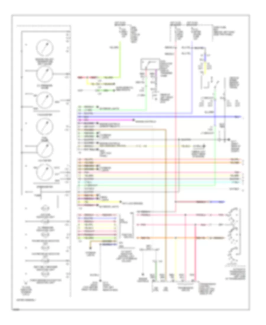
Instrument Cluster Wiring Diagram (1 of 2) for Isuzu Trooper Limited 1995
 https://portal-diagnostov.com/license.html
Automotive Electricians Portal FZCO
Automotive Electricians Portal FZCO
https://portal-diagnostov.com/license.html
https://portal-diagnostov.com/license.html
Automotive Electricians Portal FZCO
Automotive Electricians Portal FZCOList of elements for Instrument Cluster Wiring Diagram (1 of 2) for Isuzu Trooper Limited 1995:
- (rear of left front fender) g104
- 4wd indicator switch (right side of transfer case)
- A/t
- A/t shift indicator control unit (left of steering column)
- A11
- Anti-lock brakes
- Automatic transmission mode switch (left side of transmission)
- C-10 meter gauge fuse 10a
- C-21 srs-1 fuse 10a
- C-3 turn back fuse 15a
- Check engine malfunction indicator light
- Dash fuse box (behind left dash side trim panel)
- Dim
- Engine controls
- Engine controls (icm, conn e-21, pin c10)
- Engine controls (upshift relay 1)
- Engine coolant temperature (ect) gauge
- Exterior lights
- Fuel gauge
- G114 (dohc) (top left rear of eng)
- G117 (right rear of engine compt)
- G134 (sohc) (top center front of eng)
- G200 (left kick panel)
- Gnd
- H-10 (m/t)
- H-11 (a/t)
- H-24
- H-5
- H-7
- H-9
- Head- lights
- Hot in on or start
- I-10
- I-31
- I-37
- I-9
- Ign
- Ind ctrl
- Ind ctrls
- Interior lights
- Low fuel indicator light
- M/t
- Meter assembly
- Oil pressure gauge
- Oil pressure indicator light
- Out
- Pnk
- Position inputs
- Power drive indicator (a/t)
- Red
- Rpm
- Seat belt reminder indicator light
- Speedometer
- Srs fuse box (top of dash fuse box)
- Tachometer
- Thermo unit (right rear of engine)
- Timer
- To 4wd indicator (diagram 2 of 2)
- Transmission control module (tcm) (behind left side of i/p)
- Transmission inputs
- Vehicle speed sensor (rear of trans)
- Voltmeter
- Vs in
- Winter drive indicator (a/t)
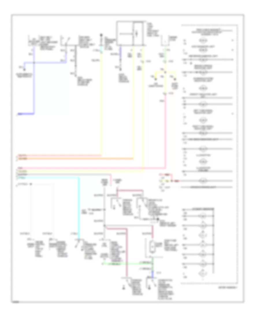
Instrument Cluster Wiring Diagram (2 of 2) for Isuzu Trooper Limited 1995
 https://portal-diagnostov.com/license.html
Automotive Electricians Portal FZCO
Automotive Electricians Portal FZCO
https://portal-diagnostov.com/license.html
https://portal-diagnostov.com/license.html
Automotive Electricians Portal FZCO
Automotive Electricians Portal FZCOList of elements for Instrument Cluster Wiring Diagram (2 of 2) for Isuzu Trooper Limited 1995:
- (diagram 1 of 2)
- 1-10
- 1-9
- 4 wheel abs
- 4wd indicator light
- A/t shift indicator
- Abs brake warning light
- Air bag warning light
- Air conditioning
- Brake fluid level switch (closed with low fluid level) (on brake fluid reservoir)
- Brake warning indicator light
- C-14
- Charging system indicator light
- Combination valve pressure differential switch (rear of eng compartment, in brake fluid valve)
- Combo switch in
- Cruise control unit (top of right kick panel)
- Dash fuse box (behind left dash side trim panel)
- Diode box 4
- Driver's seat belt switch (in seat belt buckle)
- Engine control module (behind front of front console)
- From check engine malfunction indicator a
- Fuel tank unit (top right front of fuel tank)
- G-302 (below center console)
- G104 (rear of left front fender)
- G302 (below rear of center console)
- Gener- ator
- H-16
- H-24
- H-33
- High beam indicator light
- I-10
- I-36
- I-37
- I-9
- Illumination
- Illumination (3 bulbs)
- Ind ctrl
- Left turn signal indicator light
- Meter assembly
- Not used
- Oil pressure sender unit (at oil filter)
- Oil pressure switch (closed with low pressure) (at oil filter)
- P-8
- Parking brake switch (below rear of center console)
- Pnk
- Rear wheel abs
- Rear wheel anti-lock brake controller (behind lower cluster assembly)
- Red
- Right turn signal indicator light
- Seat belt, key, and light reminder buzzer (behind right kick panel)
- Shift inter- lock
- Speed input
- Un- buckled input
- Upshift indicator light (mt)
INTERIOR LIGHTS
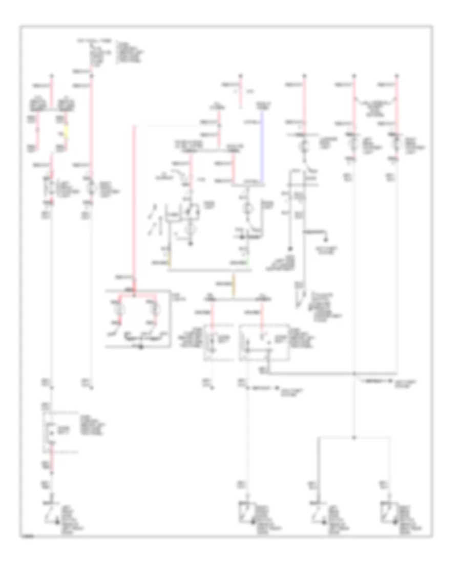
Courtesy Lamps Wiring Diagram for Isuzu Trooper Limited 1995
 https://portal-diagnostov.com/license.html
Automotive Electricians Portal FZCO
Automotive Electricians Portal FZCO
https://portal-diagnostov.com/license.html
https://portal-diagnostov.com/license.html
Automotive Electricians Portal FZCO
Automotive Electricians Portal FZCOList of elements for Courtesy Lamps Wiring Diagram for Isuzu Trooper Limited 1995:
- (center rear of luggage compartment floor)
- Acura & isuzu ls, se, limited models
- All models except isuzu rs model
- All others
- Anti-theft system
- C-16 clock (b) room fuse 10a
- Dash fuse box (behind left dash side trim panel)
- Diode box 1
- Diode box 3
- Dome light
- Door
- G404 (left side of luggage compartment)
- H-21
- H-45
- Hot at all times
- Isuzu rs model
- Isuzu s model
- Left front courtesy light
- Left front door switch (rear of left front door)
- Left rear courtesy light
- Left rear door switch (rear of left rear door)
- Luggage room light
- Map lights
- Off
- Red
- Right front courtesy light
- Right front door switch (rear of right front door)
- Right rear courtesy light
- Right rear door switch (rear of right rear door)
- Rs model
- Tailgate switch
- Timer
- W/ remote keyless entry
- W/ sunroof
- W/o remote keyless entry
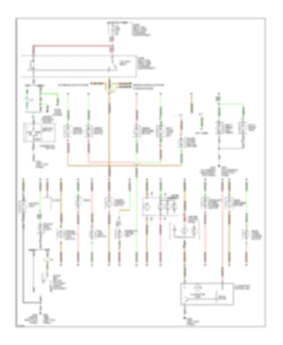
Instrument Illumination Wiring Diagram for Isuzu Trooper Limited 1995
 https://portal-diagnostov.com/license.html
Automotive Electricians Portal FZCO
Automotive Electricians Portal FZCO
https://portal-diagnostov.com/license.html
https://portal-diagnostov.com/license.html
Automotive Electricians Portal FZCO
Automotive Electricians Portal FZCOList of elements for Instrument Illumination Wiring Diagram for Isuzu Trooper Limited 1995:
- (not used)
- 1996-97
- A/t
- Ashtray light
- Cigarette lighter light
- Clock
- Combination switch
- Cruise control main switch
- Door locks system
- Engine controls system
- Exterior lights system
- Fog light switch
- Fuse/ relay box (right side of engine compartment)
- G200 (1995) (left kick panel)
- G200 (left kick panel)
- G201 (w/ sunroof) (above right kick panel)
- G203 (1996-97) (right kick panel)
- G203 (w/o sunroof) (right kick panel)
- Glove box light
- Glove box switch (top right side of glove box)
- H-12
- Hazard warning switch
- Head
- Headlight wiper/ washer switch
- Heater control panel
- Hot at all times
- I-10
- I-24
- I-9
- Illumination controller
- Illumination lamp
- Lighting switch
- M/t
- Meter assembly
- Mirror control switch
- Mirror defogger switch
- Mirror folding switch
- Multi- meter (1997)
- Off
- Park
- Power/ winter switch (2 bulbs)
- Radio
- Rear defogger switch
- Rear wiper/ washer switch
- Red
- Shift lever light (a/t)
- Solid state
- Tail fuse f-12 15a
- Taillight relay
- Vanity mirror light (1996-97)
- Warning system
POWER ANTENNA
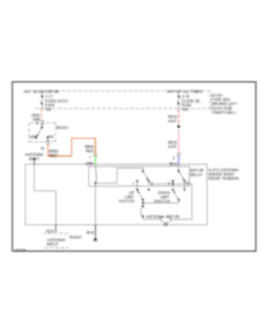
Power Antenna Wiring Diagram for Isuzu Trooper Limited 1995
 https://portal-diagnostov.com/license.html
Automotive Electricians Portal FZCO
Automotive Electricians Portal FZCO
https://portal-diagnostov.com/license.html
https://portal-diagnostov.com/license.html
Automotive Electricians Portal FZCO
Automotive Electricians Portal FZCOList of elements for Power Antenna Wiring Diagram for Isuzu Trooper Limited 1995:
- Antenna input
- Antenna mast
- Antenna motor
- Auto antenna (inside right front fender)
- C-11 audio (acc) fuse 10a
- C-16 clock (b) fuse 10a
- Dash fuse box (behind left dash side trim panel)
- Down limit switch
- Hot at all times
- Hot in acc or on
- Motor relay
- Nca
- Off
- Radio
- Up limit switch
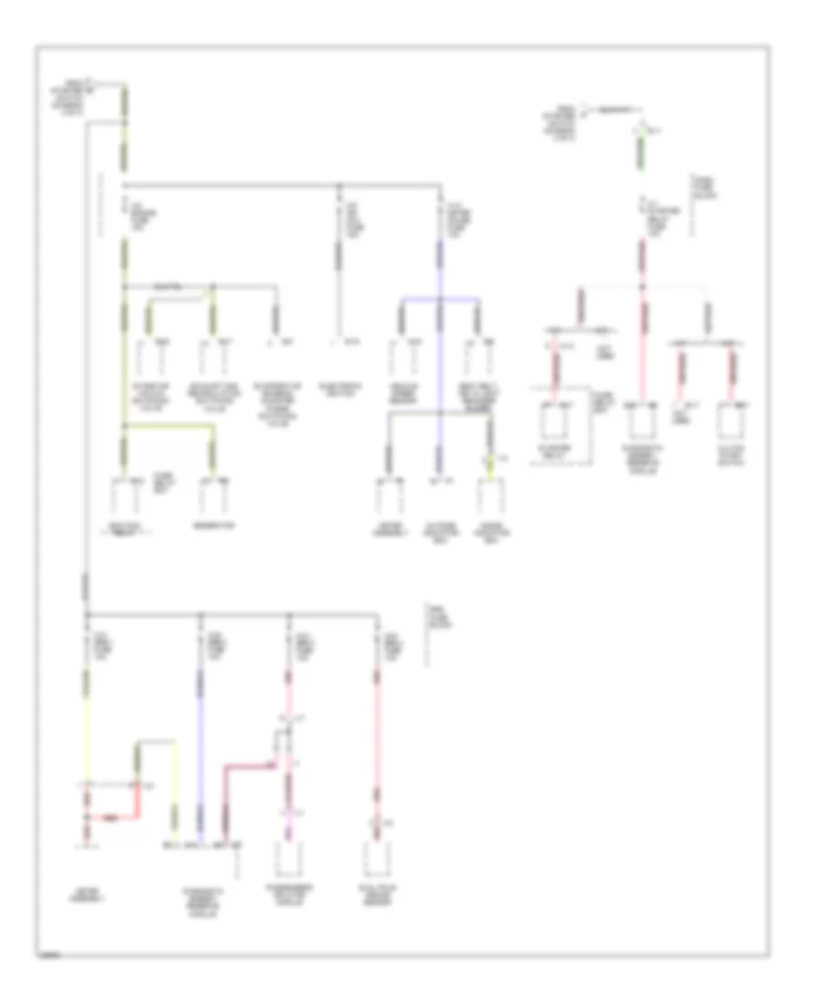
POWER DISTRIBUTION
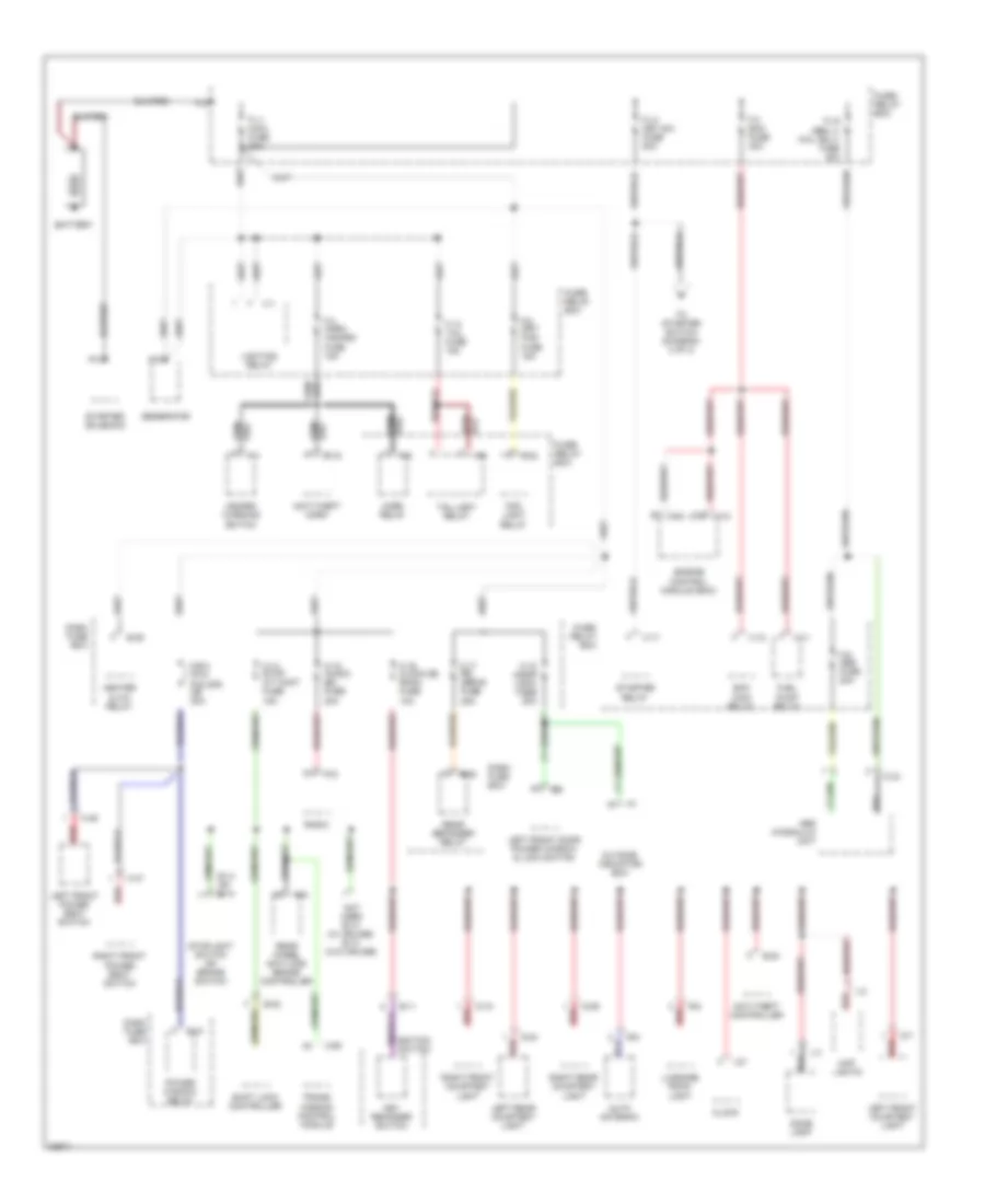
Power Distribution Wiring Diagram (1 of 3) for Isuzu Trooper Limited 1995
 https://portal-diagnostov.com/license.html
Automotive Electricians Portal FZCO
Automotive Electricians Portal FZCO
https://portal-diagnostov.com/license.html
https://portal-diagnostov.com/license.html
Automotive Electricians Portal FZCO
Automotive Electricians Portal FZCOList of elements for Power Distribution Wiring Diagram (1 of 3) for Isuzu Trooper Limited 1995:
- Abs hydraulic unit
- Anti-theft controller
- Anti-theft horn
- Auto antenna
- B-11
- B-14 or b-13
- B-20
- B-32
- B-36
- B-37
- B-38
- B-8
- Battery
- C-1
- C-14 stop a/t cont fuse 15a
- C-15 (audio [b]) fuse 20a
- C-16 clock [b] room fuse 10a
- C-17 rr defog fuse 25a
- C-18 (door lock) fuse 20a
- C-19
- C-2
- C-33
- C-5
- C-90
- C/b-2 (p/w, p/s, s/r) cb 30a
- C16
- Clock
- D-18
- D-24
- D-29
- D-5
- D-7
- Dash fuse box
- Dome light
- Ecm main relay
- Engine control module (ecm)
- F-12 tail fuse 15a
- F-3 ecm fuse 30a
- F-3 horn hazard fuse 15a
- F-8 (frt fog) fuse 15a
- F-9 abs fuse 20a
- Fl-1 main fuse 80a
- Fl-2 key sw. fuse 50a
- Fl-6 (abs, 4- whl only) fuse 40a
- Fog light relay
- Fuel pump relay
- Fuse/ relay box
- Generator
- H-46
- H-47
- Hazard warning switch
- Heater & a/c relay
- Horn relay
- I-1
- I-11
- I-15
- I-27
- Ignition switch
- Key reminder switch
- L-2
- L-3
- Left front courtesy light
- Left front door power window & lock switch
- Left front power seat switch
- Left rear courtesy light
- Lighting relay
- Luggage room light
- Map lights
- Not used b-14 (w/ cruise) b-13 (w/o cruise)
- Outside indicator box
- P-2
- P-4
- P-9
- Power window relay
- R-6
- Radio
- Rear defogger relay
- Rear wheel anti-lock brake controller
- Red
- Right front courtesy light
- Right front power seat switch
- Right rear courtesy light
- Shift lock controller
- Starter relay
- Starter solenoid
- Stoplight switch or brake switch
- Taillight relay
- To starter switch (diagram 2 of 3)
- Trans- mission control module
- X-1
- X-11
- X-12
- X-17
- X-23
- X-8
- X-9
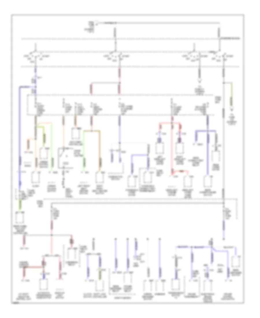
Power Distribution Wiring Diagram (2 of 3) for Isuzu Trooper Limited 1995
 https://portal-diagnostov.com/license.html
Automotive Electricians Portal FZCO
Automotive Electricians Portal FZCO
https://portal-diagnostov.com/license.html
https://portal-diagnostov.com/license.html
Automotive Electricians Portal FZCO
Automotive Electricians Portal FZCOList of elements for Power Distribution Wiring Diagram (2 of 3) for Isuzu Trooper Limited 1995:
- (a/t)
- (m/t)
- A/t
- A/t shift indicator control unit
- Abs
- Acc
- Anti-theft controller
- Automatic transmission mode switch
- B-11
- B-16
- B-20
- B-25
- B-31
- B-32
- B-37
- B-38
- B-52
- B-55
- B-56
- B-57
- B-9
- Back-up light switch
- C-12 cigar fuse 20a
- C-13 (anti- theft) fuse 10a
- C-2 (seat heater) fuse 15a
- C-23
- C-3 turn back fuse 15a
- C-30
- C-36
- C-38
- C-4
- C-4 elec. ign. fuse 10a
- C-43
- C-44
- C-5
- C-5 frt wiper & washer fuse 15a
- C-6 rr wiper & washer fuse 10a
- C-7 (h/lamp wiper) fuse 10a
- C-93
- C189
- Cb-21
- Cigar- ette lighter
- Clock
- Clutch switch
- Combination switch
- Cornering relay
- Cruise control main switch
- Cruise main relay
- Dash fuse box
- Electronic brake control module
- F-9 abs fuse 20a
- From fuse fl-2 (diagram 1 of 3)
- Fuse/ relay box
- G-6
- G-sensor
- G203 (right kick panel)
- H-10
- H-13
- H-24
- Hazard warning switch
- Headlight washer motor
- Headlight wiper timer motor
- I-11
- I-15
- I-16
- I-17
- I-21
- I-22
- I-27
- I-6
- Left front seat heater switch
- Left headlight wiper motor
- Lock
- M-1
- M/t
- Mirror control switch
- Mirror defogger switch
- Mirror folding switch
- Not used
- Off
- Power window relay
- Radio
- Rear defogger relay
- Rear defogger switch
- Rear intermittent wiper relay
- Rear wheel antilock brake controller
- Rear wiper motor
- Rear wiper/washer switch
- Red
- Right front seat heater switch
- Right headlight wiper motor
- Rwal
- Shift lock controller
- Start
- Starter switch
- To fuse c-1 (diagram 3 of 3)
- To fuse c-8 (diagram 3 of 3)
- Transmission switch 1-2
- Windshield intermittent wiper relay
- Windshield wiper motor
- X-13
- X-20
- X-22
Power Distribution Wiring Diagram (3 of 3) for Isuzu Trooper Limited 1995
 https://portal-diagnostov.com/license.html
Automotive Electricians Portal FZCO
Automotive Electricians Portal FZCO
https://portal-diagnostov.com/license.html
https://portal-diagnostov.com/license.html
Automotive Electricians Portal FZCO
Automotive Electricians Portal FZCOList of elements for Power Distribution Wiring Diagram (3 of 3) for Isuzu Trooper Limited 1995:
- A/t
- A10
- B-11
- B-17
- B-6
- B10
- C-1 starter relay fuse 10a
- C-10 meter gauge fuse 10a
- C-21 srs-1 fuse 10a
- C-22 srs-2 fuse 10a
- C-23 srs-3 fuse 10a
- C-24 srs-4 fuse 10a
- C-8 engine fuse 15a
- C-9 ign coil fuse 15a
- Clutch start switch
- Dash fuse block
- Diagnostic energy reserve module
- Dual pole arming sensor
- E-17
- E-18
- E-23
- E-8
- Ecm main relay
- Electronic ignition
- Evaporative emission canister purge switching valve
- Exhaust gas recirculation switching valve
- From starter switch (diagram 2 of 3)
- Fuse/ relay box
- Generator
- H-12
- I-1
- I-13
- I-37
- I-9
- Inside indicator box
- Intake air vacuum switching valve
- M-10
- M/t
- Meter assembly
- Not used
- Outside indicator box
- P-8
- Passenger's inflator module
- Pnk
- Red
- Seat belt, key & light reminder buzzer
- Srs fuse block
- Starter relay
- U-1
- U-5
- U-7
- U-8
- Vehicle speed sensor
- X-12
- X-17
POWER DOOR LOCKS
Power Door Lock Wiring Diagram for Isuzu Trooper Limited 1995
 https://portal-diagnostov.com/license.html
Automotive Electricians Portal FZCO
Automotive Electricians Portal FZCO
https://portal-diagnostov.com/license.html
https://portal-diagnostov.com/license.html
Automotive Electricians Portal FZCO
Automotive Electricians Portal FZCOList of elements for Power Door Lock Wiring Diagram for Isuzu Trooper Limited 1995:
- C-18 door lock fuse 20a
- C-4 elec ign fuse 10a
- C/b-2 p/w, p/s, s/r cb 30a
- Control unit
- D-30
- D-5
- Dash fuse box (behind left dash side trim panel)
- Door lock switch
- G200 (left kick panel)
- G202 (behind lower left dash panel)
- G203 (right kick panel)
- H-28
- Hot at all times
- Left front door lock actuator/switch
- Left front door lock key switch
- Left front door power window and lock switch
- Left rear door lock actuator/switch
- Lock
- Lock relay
- Power window relay
- Power windows
- Red
- Right front door lock actuator/switch
- Right front door lock key switch
- Right front door power window and lock switch
- Right rear door lock actuator/switch
- Tailgate door lock actuator/switch
- Unlock
- Unlock relay
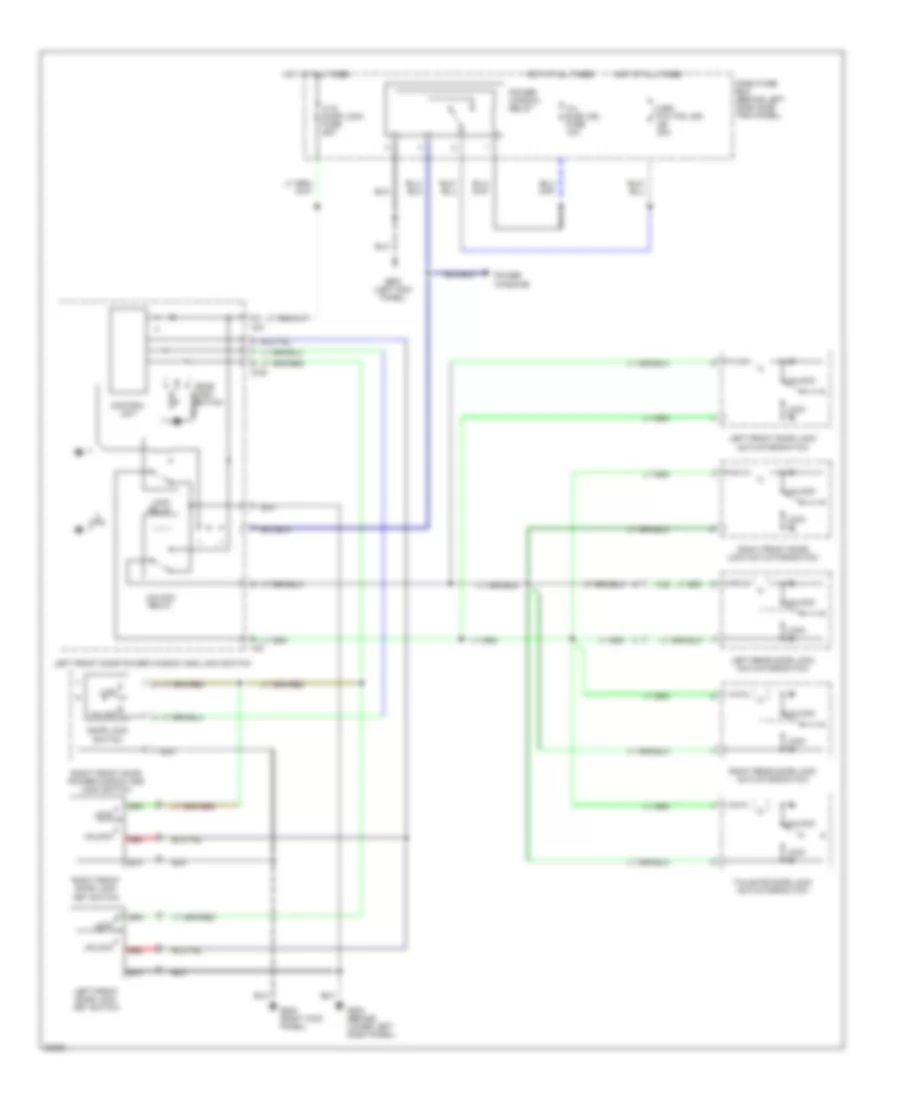
POWER MIRRORS
Power Mirror Wiring Diagram for Isuzu Trooper Limited 1995
 https://portal-diagnostov.com/license.html
Automotive Electricians Portal FZCO
Automotive Electricians Portal FZCO
https://portal-diagnostov.com/license.html
https://portal-diagnostov.com/license.html
Automotive Electricians Portal FZCO
Automotive Electricians Portal FZCOList of elements for Power Mirror Wiring Diagram for Isuzu Trooper Limited 1995:
- Close
- Dash fuse box (behind left dash side trim panel)
- Defogger system
- Fold
- Folding motor
- G200 (1995 isuzu) (left kick panel)
- G302 (1996-97 isuzu) (1997 acura) (below center console)
- Hot in acc or on
- Illumination lamp
- Interior lights system
- Left
- Left door mirror
- Left/right motor
- Mirror control switch
- Mirror defogger
- Mirror folding switch
- Mirror fuse c-11 10a
- Mirror selector switch
- Open
- Pnk
- Red
- Return
- Right
- Right door mirror
- Switch 1
- Switch 2
- Switch 3
- Switch 4
- Up/down motor
- W/ remote keyless entry
POWER SEATS
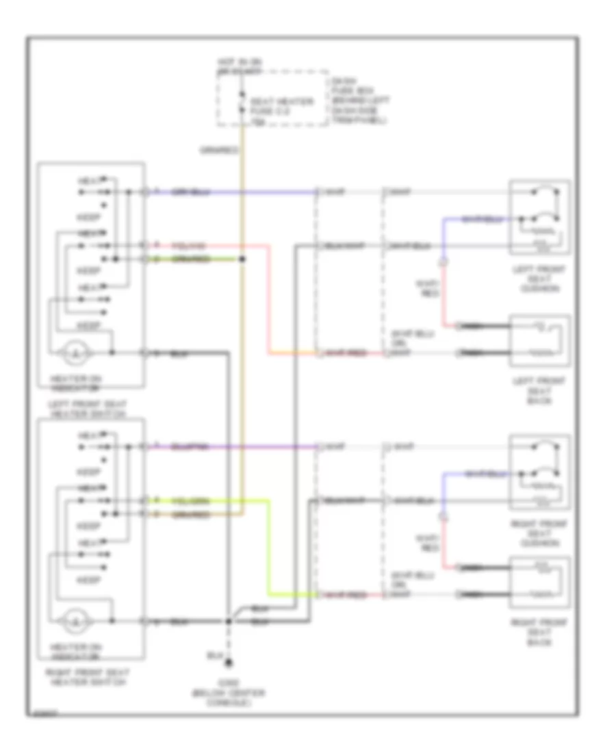
Heated Seats Wiring Diagram for Isuzu Trooper Limited 1995
 https://portal-diagnostov.com/license.html
Automotive Electricians Portal FZCO
Automotive Electricians Portal FZCO
https://portal-diagnostov.com/license.html
https://portal-diagnostov.com/license.html
Automotive Electricians Portal FZCO
Automotive Electricians Portal FZCOList of elements for Heated Seats Wiring Diagram for Isuzu Trooper Limited 1995:
- Dash fuse box (behind left dash side trim panel)
- G302 (below center console)
- Heat
- Heater on indicator
- Hot in on or start
- Keep
- Left front seat back
- Left front seat cushion
- Left front seat heater switch
- Nca
- Right front seat back
- Right front seat cushion
- Right front seat heater switch
- Seat heater fuse c-2 15a
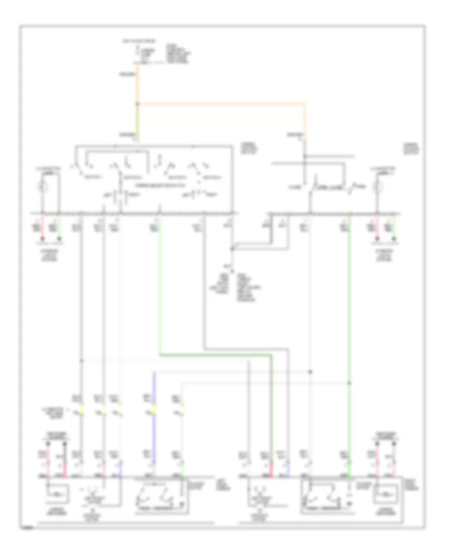
Power Seats Wiring Diagram for Isuzu Trooper Limited 1995
 https://portal-diagnostov.com/license.html
Automotive Electricians Portal FZCO
Automotive Electricians Portal FZCO
https://portal-diagnostov.com/license.html
https://portal-diagnostov.com/license.html
Automotive Electricians Portal FZCO
Automotive Electricians Portal FZCOList of elements for Power Seats Wiring Diagram for Isuzu Trooper Limited 1995:
- Dash fuse box (behind left dash side trim panel)
- Down
- Front
- G302 (below center console)
- H-46
- H-47
- Hot at all times
- Left front power seat switch
- Left front seat recline motor & switch
- Left front seat slide motor
- Left front seat tilt motor & switch (front)
- Left front seat tilt motor & switch (rear)
- P/w, p/s, s/r circuit breaker c/b-2 30a
- Rear
- Recline switch
- Red
- Right front power seat switch
- Right front seat recline motor and switch
- Right front seat slide motor
- Slide switch
- T-1
- T-11
- T-12
- T-13
- T-2
- T-3
- T-4
- T-5
- T-6
- T-7
- T-9
- Tilt & slide switch
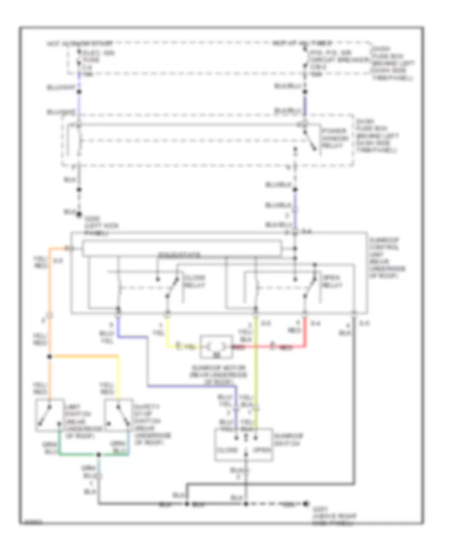
POWER TOP/SUNROOF
Sunroof Wiring Diagram for Isuzu Trooper Limited 1995
 https://portal-diagnostov.com/license.html
Automotive Electricians Portal FZCO
Automotive Electricians Portal FZCO
https://portal-diagnostov.com/license.html
https://portal-diagnostov.com/license.html
Automotive Electricians Portal FZCO
Automotive Electricians Portal FZCOList of elements for Sunroof Wiring Diagram for Isuzu Trooper Limited 1995:
- (rear underside of roof)
- Close
- Close relay
- Dash fuse box (behind left dash side trim panel)
- Elec. ign. fuse c-4 10a
- G200 (left kick panel)
- G201 (above right kick panel)
- Hot at all times
- Hot in on or start
- Limit switch
- Open relay
- P/w, p/s, s/r circuit breaker c/b-2 30a
- Power window relay
- Red
- S-4
- S-5
- Safety stop switch (rear underside of roof)
- Solid-state
- Sunroof control unit (rear underside of roof)
- Sunroof motor (rear underside of roof)
- Sunroof switch open
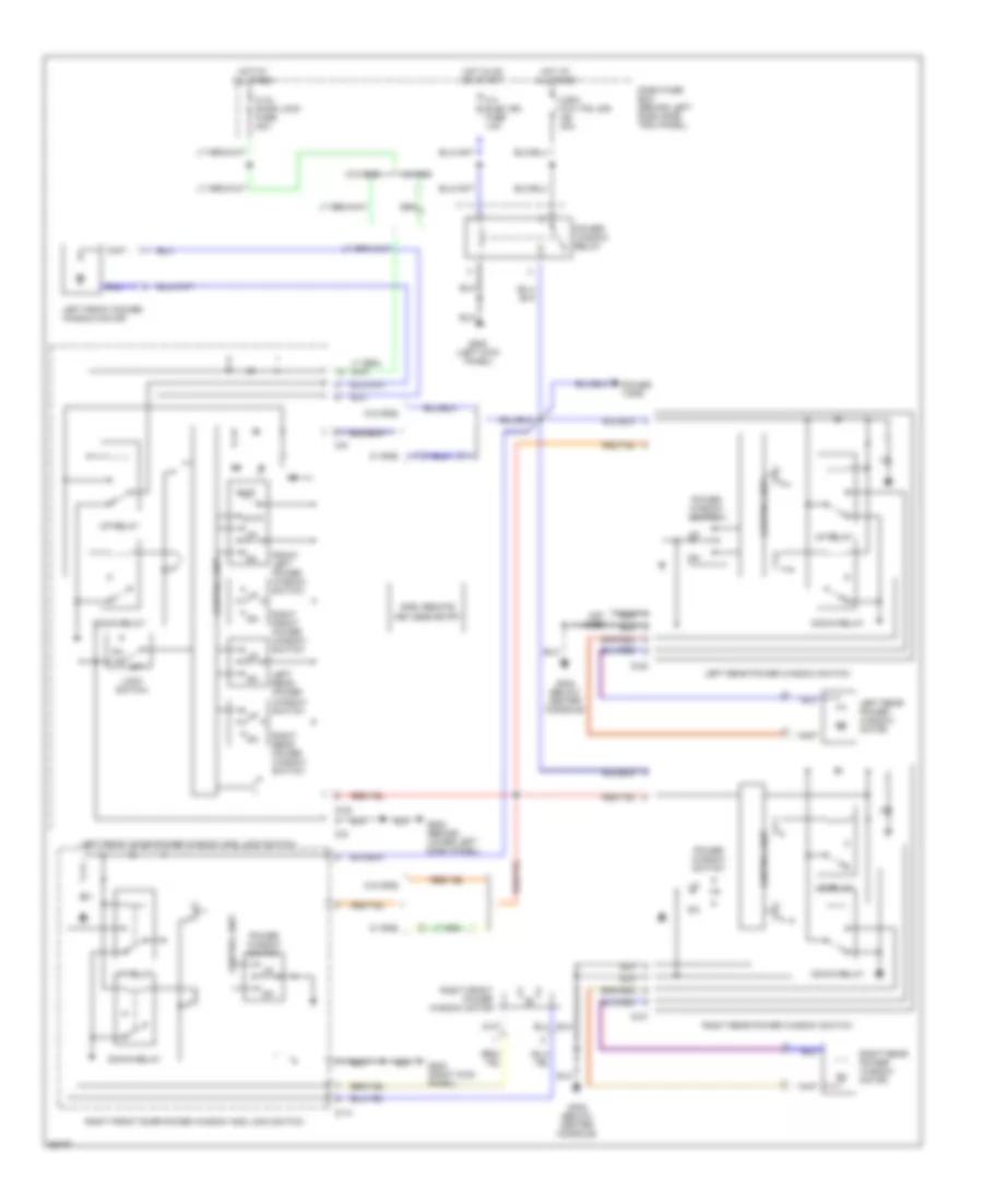
POWER WINDOWS
Power Window Wiring Diagram for Isuzu Trooper Limited 1995
 https://portal-diagnostov.com/license.html
Automotive Electricians Portal FZCO
Automotive Electricians Portal FZCO
https://portal-diagnostov.com/license.html
https://portal-diagnostov.com/license.html
Automotive Electricians Portal FZCO
Automotive Electricians Portal FZCOList of elements for Power Window Wiring Diagram for Isuzu Trooper Limited 1995:
- Auto
- C-18 door lock fuse 20a
- C-4 elec ign fuse 10a
- C/b-2 p/w, p/s, s/r cb 30a
- Control unit
- D-14
- D-22
- D-27
- D-30
- D-5
- Dash fuse box (behind left dash side trim panel)
- Down relay
- Front left power window switch
- G200 (left kick panel)
- G202 (behind lower left dash panel)
- G203 (right kick panel)
- G302 (below center console)
- Hot at all times
- Hot in on or start
- Left front door power window and lock switch
- Left front power window motor
- Left rear power window motor
- Left rear power window switch
- Lock switch
- Not used
- Off
- Power tops
- Power window relay
- Power window switch
- Red/yrl
- Right front door power window and lock switch
- Right front power window motor
- Right front power window switch
- Right rear power window motor
- Right rear power window switch
- Rke: remote keyless entry
- Up relay
- W/ rke
- W/o rke
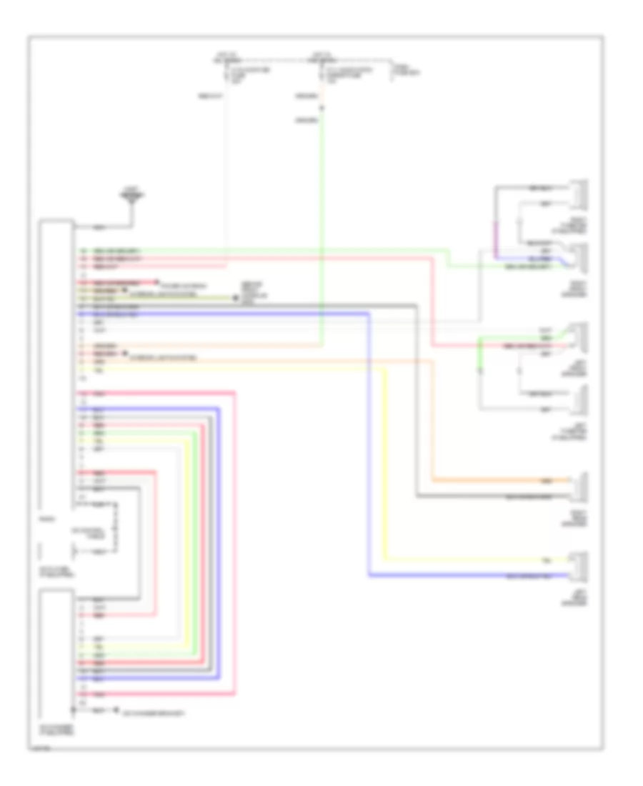
RADIO
Radio Wiring Diagrams for Isuzu Trooper Limited 1995
 https://portal-diagnostov.com/license.html
Automotive Electricians Portal FZCO
Automotive Electricians Portal FZCO
https://portal-diagnostov.com/license.html
https://portal-diagnostov.com/license.html
Automotive Electricians Portal FZCO
Automotive Electricians Portal FZCOList of elements for Radio Wiring Diagrams for Isuzu Trooper Limited 1995:
- (behind front console) g302
- (cd changer bracket)
- C-11 (audio [acc]) mirror fuse 10a
- C-15 (audio [b]) fuse 20a
- Cd changer (if equipped)
- Cd control cable
- Cd player (if equipped)
- Dash fuse box
- Hot at all times
- Hot in acc or on
- I15
- I41
- I42
- Interior lights system
- Left front speaker
- Left rear speaker
- Left tweeter (if equipped)
- Mast antenna
- Nca
- Pnk
- Power antenna
- Radio
- Red
- Right front speaker
- Right rear speaker
- Right tweeter (if equipped)
SHIFT INTERLOCKS
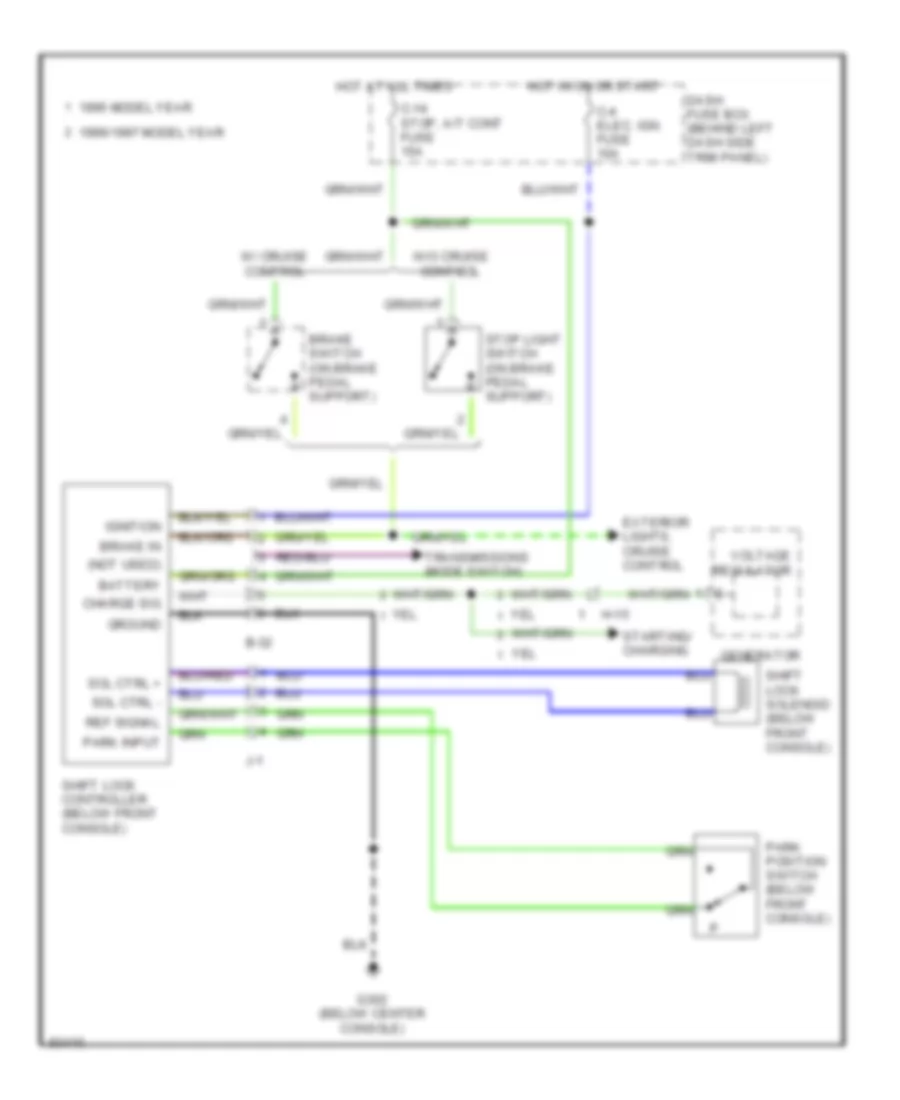
Shift Interlock Wiring Diagram for Isuzu Trooper Limited 1995
 https://portal-diagnostov.com/license.html
Automotive Electricians Portal FZCO
Automotive Electricians Portal FZCO
https://portal-diagnostov.com/license.html
https://portal-diagnostov.com/license.html
Automotive Electricians Portal FZCO
Automotive Electricians Portal FZCOList of elements for Shift Interlock Wiring Diagram for Isuzu Trooper Limited 1995:
- (not used)
- 1995 model year
- 1996/1997 model year
- B-32
- Battery
- Brake in
- Brake switch (on brake pedal support)
- C-14 stop, a/t cont fuse 15a
- C-4 elec. ign. fuse 10a
- Charge sig
- Dash fuse box (behind left dash side trim panel)
- Exterior lights, cruise control
- G302 (below center console)
- Generator
- Ground
- H-15
- Hot at all times
- Hot in on or start
- Ignition
- J-1
- Park input
- Park position switch (below front console)
- Ref signal
- Shift lock controller (below front console)
- Shift lock solenoid (below front console)
- Sol ctrl +
- Sol ctrl -
- Starting/ charging
- Stop light switch (on brake pedal support)
- Transmissions (mode switch)
- Voltage regulator
- W/ cruise control
- W/o cruise control
STARTING/CHARGING
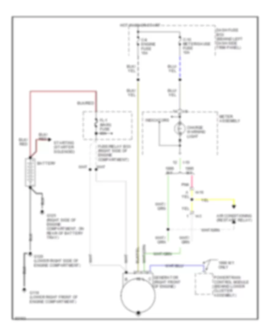
Charging Wiring Diagram for Isuzu Trooper Limited 1995
 https://portal-diagnostov.com/license.html
Automotive Electricians Portal FZCO
Automotive Electricians Portal FZCO
https://portal-diagnostov.com/license.html
https://portal-diagnostov.com/license.html
Automotive Electricians Portal FZCO
Automotive Electricians Portal FZCOList of elements for Charging Wiring Diagram for Isuzu Trooper Limited 1995:
- 1996 m.y. only
- Air conditioning (restart relay)
- Battery
- C-10 meter/gauge fuse 10a
- C-8 engine fuse 15a
- Charge warning light
- Dash fuse box (behind left dash side trim panel)
- Fl-1 (main) fuse 80a
- Fuse/relay box (right side of engine compartment)
- G119 (lower right front of engine compartment)
- G120 (lower right side of engine compartment)
- G125 (right side of engine compartment, on rear of battery tray)
- Generator (right front of engine)
- H-16
- H-3
- Hot in on or start
- I-10
- I-9
- Indicators
- M.y.
- Meter assembly
- Pnk
- Powertrain control module (behind lower cluster assembly)
- Starting (starter solenoid)
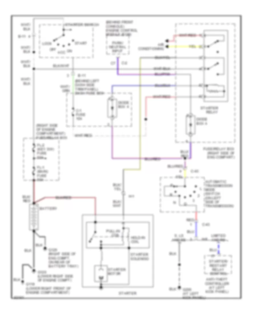
Starting Wiring Diagram, A/T for Isuzu Trooper Limited 1995
 https://portal-diagnostov.com/license.html
Automotive Electricians Portal FZCO
Automotive Electricians Portal FZCO
https://portal-diagnostov.com/license.html
https://portal-diagnostov.com/license.html
Automotive Electricians Portal FZCO
Automotive Electricians Portal FZCOList of elements for Starting Wiring Diagram, A/T for Isuzu Trooper Limited 1995:
- (behind front console) engine control module (ecm)
- (behind left dash side trim panel) dash fuse box
- (right side of engine compartment) fuse/relay box
- Air conditioning
- Anti-theft controller (at left kick panel)
- Automatic transmission mode switch (on left side of transmission)
- B-11
- Battery
- C-1 fuse 10a
- C-2
- C-43
- Diode box 4
- Diode box a
- Fl-1 (main) fuse 80a
- Fl-2 (key sw) fuse 50a
- Fuse/relay box (right side of eng compart)
- G119 (lower right front of engine compartment)
- G120 (lower right side of engine compt)
- G125 (right side of eng compt, on rear of battery tray)
- G200 (at left kick panel)
- H-1
- H-8
- Hold-in coil
- Limited and rs
- Lock
- Off acc
- Park/ neutral input
- Pull-in coil
- Red
- S, ls and se
- Start
- Starter
- Starter motor
- Starter relay
- Starter solenoid
- Starter switch
- Starter/ restart relay control
Starting Wiring Diagram, M/T for Isuzu Trooper Limited 1995
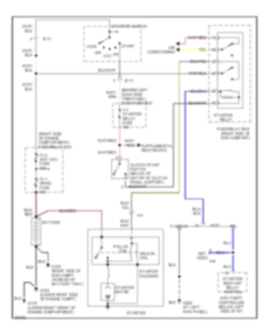 https://portal-diagnostov.com/license.html
Automotive Electricians Portal FZCO
Automotive Electricians Portal FZCO
https://portal-diagnostov.com/license.html
https://portal-diagnostov.com/license.html
Automotive Electricians Portal FZCO
Automotive Electricians Portal FZCOList of elements for Starting Wiring Diagram, M/T for Isuzu Trooper Limited 1995:
- (behind left dash side trim panel) dash fuse box
- (right side of engine compartment) fuse/relay box
- Air conditioning
- Anti-theft controller (below left side of i/p)
- B-11
- Battery
- C-1 starter relay fuse 10a
- Clutch start switch (below i/p, on top of clutch pedal support)
- Fl-1 (main) fuse 80a
- Fl-2 (key sw) fuse 50a
- Fuse/relay box (right side of eng compart)
- G119 (lower right front of engine compartment)
- G120 (lower right side of engine compt)
- G125 (right side of eng compt, on rear of battery tray)
- G200 (at left kick panel)
- H-1
- H-12
- H-8
- Hold-in coil
- Lock
- Not used
- Off acc
- Pull-in coil
- S and ls
- Start
- Starter
- Starter motor
- Starter relay
- Starter solenoid
- Starter switch
- Starter/ restart relay control
SUPPLEMENTAL RESTRAINTS
Supplemental Restraint Wiring Diagram for Isuzu Trooper Limited 1995
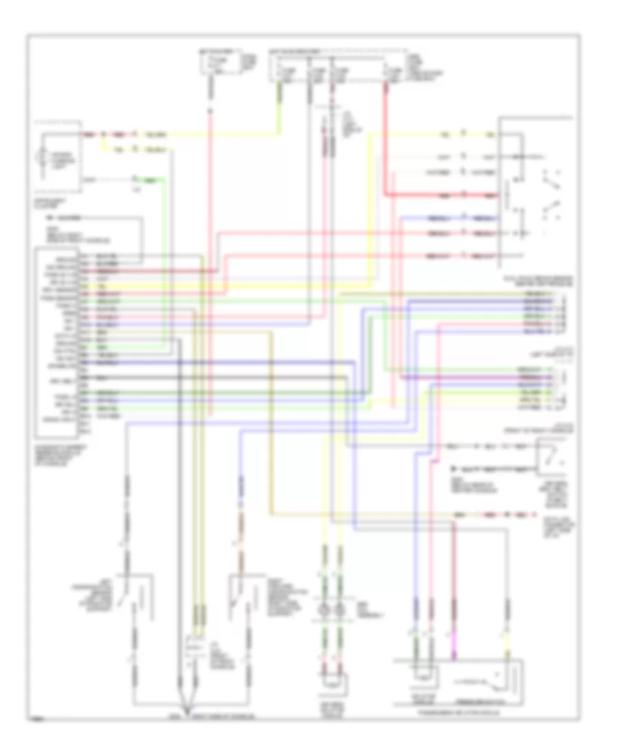 https://portal-diagnostov.com/license.html
Automotive Electricians Portal FZCO
Automotive Electricians Portal FZCO
https://portal-diagnostov.com/license.html
https://portal-diagnostov.com/license.html
Automotive Electricians Portal FZCO
Automotive Electricians Portal FZCOList of elements for Supplemental Restraint Wiring Diagram for Isuzu Trooper Limited 1995:
- (right side of console)
- A10
- A11
- A12
- Air bag warning light
- B10
- B11
- B12
- Crank input
- Dash fuse box
- Data i/o
- Data link connector (left side of i/p)
- Diagnostic energy reserve module (behind front of console)
- Dreq
- Dri 36 vlr
- Dri hi
- Driv belt
- Driv sensor
- Driver's inflator module
- Driver's seat belt switch (in belt buckle)
- Dual pole arming sensor (behind center of i/p)
- Fuse c-1 10a
- Fuse c-21 10a
- Fuse c-22 10a
- Fuse c-23 10a
- Fuse c-24 10a
- G302
- G302 (below rear of center console)
- G302 (below right side of front console)
- Ground
- Hot in on or start
- Hot in start
- I-37
- Ign 1
- Ind ctrl
- Ind ground
- Ind ign1
- Inflator module
- Instrument cluster
- J/c (u-4) (front of front console)
- J/c (u-7) (left side of i/p)
- Left discrimination sensor (left side of radiator support)
- Pass 36 vlr
- Pass hi
- Pass lo
- Pass sensor
- Passenger's inflator module
- Pnk
- Pressure switch
- Red
- Right forward discrimination sensor (right side of radiator support)
- Spare/lps
- Srs coil assembly
- Srs fuse box (above dash fuse box)
TRANSMISSION
Transmission Wiring Diagram for Isuzu Trooper Limited 1995
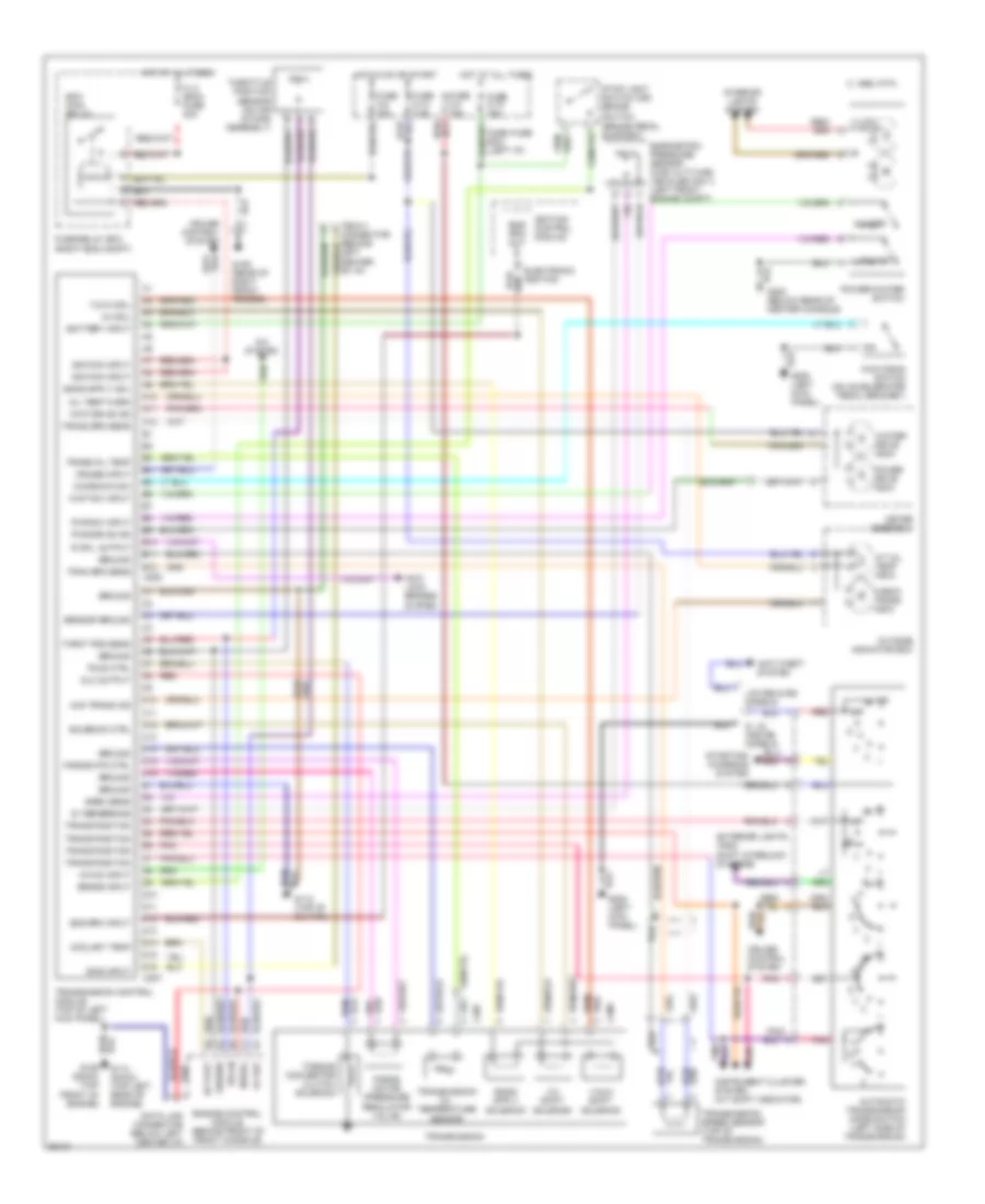 https://portal-diagnostov.com/license.html
Automotive Electricians Portal FZCO
Automotive Electricians Portal FZCO
https://portal-diagnostov.com/license.html
https://portal-diagnostov.com/license.html
Automotive Electricians Portal FZCO
Automotive Electricians Portal FZCOList of elements for Transmission Wiring Diagram for Isuzu Trooper Limited 1995:
- (brake pedal support)
- (or)
- (right eng compt)
- 1-2/3-4 shift solenoid
- 1-2/3-4 sol
- 1995 vftc c
- 2-3 shift solenoid
- 2-3 sol
- 5v ref
- 5v reference
- A/c on input
- A/c system
- A/t oil temp indic
- A10
- A11
- A12
- Anti- lock brakes system
- Anti-theft system
- Automatic transmission mode switch (left side of transmission)
- B10
- B11
- B12
- Baro sens
- Barometric pressure sensor (high altitude vehicles only) (left front engine compt)
- Battery input
- Brake input
- C10
- C11
- C12
- C13
- C14
- C15
- C16
- C207
- C208
- C307
- C308
- Check trans indic
- Chk trans ind
- Coolant temp
- Cruise control system
- Cruise input
- D10
- D11
- D12
- D13
- D14
- D15
- D16
- Dash fuse box (left i/p)
- Data link connector (below left center i/p)
- Diag input
- Dlc output
- Ecm main relay
- Ect out
- Electronic ignition
- Eng rpm input
- Eng rpm out
- Engine control module (behind front of front console)
- Exterior lights (and) shift interlock systems
- Fl-3 (ecm) fuse 30a
- Force motor (pressure regulator valve)
- Force mtr ctrl
- Fuse c-10 7.5a
- Fuse c-14 15a
- Fuse c-3 15a
- Fuse c-8 15a
- Fuse/relay box
- G105 (rear of right front fender)
- G112 (top of oil pan)
- G114 (dohc) (top left rear of engine)
- G200 (left kick panel)
- Ground
- Hot at all times
- Hot in on or start
- Ignition control module
- Ignition input
- Illum.
- Instrument cluster system (a/t shift indicator)
- Interior lights system
- Kick down switch (on accelerator pedal bracket)
- Kickdown sw
- Limited & rs models
- Meter assembly
- Oil temp warn
- Outside indicator box
- Pnk
- Pnk/
- Power
- Power drive indic
- Power/winter switch
- Pwr drive ind
- Pwr sw input
- R or l output
- Red
- S, ls, and se models
- Sensor ground
- Serial
- Solenoid ctrl
- Starting/ charging system
- Stop light switch brake switch
- Tccs ctrl
- Tech-1 connector (behind left center of i/p)
- Throt pos sens
- Throttle position sensor (on air intake assembly)
- Torque convertor clutch solenoid
- Tps in
- Tran spd sens
- Trans oil temp
- Trans position
- Trans spd sens
- Transmission
- Transmission control module (top of left kick panel)
- Transmission oil temperature sensor
- Transmission speed sensor (top of transmission)
- Wint drive ind
- Wint sw input
- Winter
- Winter drive indic
WARNING SYSTEMS
Warning System Wiring Diagrams for Isuzu Trooper Limited 1995
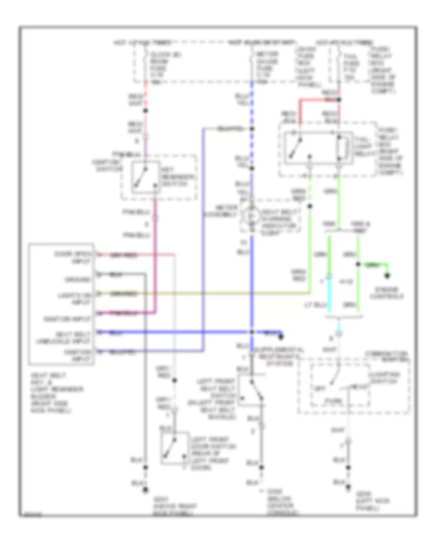 https://portal-diagnostov.com/license.html
Automotive Electricians Portal FZCO
Automotive Electricians Portal FZCO
https://portal-diagnostov.com/license.html
https://portal-diagnostov.com/license.html
Automotive Electricians Portal FZCO
Automotive Electricians Portal FZCOList of elements for Warning System Wiring Diagrams for Isuzu Trooper Limited 1995:
- 1996 &
- Clock (b) room fuse c-16 10a
- Combination switch
- Dash fuse box (left kick panel)
- Door open
- Engine controls
- Fuse/ relay box (right side of engine compt)
- G200 (left kick panel)
- G201 (above right kick panel)
- G302 (below center console)
- Ground
- H-12
- Head
- Hot at all times
- Hot in on or start
- Ignition
- Ignition input
- Input
- Key reminder switch
- Left front door switch (rear of left front door)
- Left front seat belt switch (in left front seat belt buckle)
- Lighting switch
- Lights on input
- Meter assembly
- Meter gauge fuse c-10 10a
- Off
- Park
- Seat belt unbuckle input
- Seat belt warning indicator light
- Seat belt, key, & light reminder buzzer (right side kick panel)
- Switch
- Tail fuse f-12 15a
- Tail- light relay
WIPER/WASHER
Front Wiper/Washer Wiring Diagram for Isuzu Trooper Limited 1995
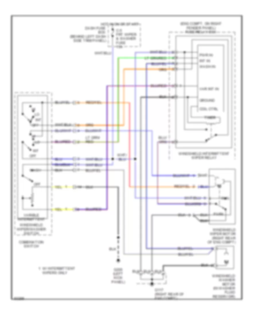 https://portal-diagnostov.com/license.html
Automotive Electricians Portal FZCO
Automotive Electricians Portal FZCO
https://portal-diagnostov.com/license.html
https://portal-diagnostov.com/license.html
Automotive Electricians Portal FZCO
Automotive Electricians Portal FZCOList of elements for Front Wiper/Washer Wiring Diagram for Isuzu Trooper Limited 1995:
- (eng compt, on right fender panel) fuse/relay box
- C-5 frt wiper & washer fuse 15a
- Coil ctrl
- Combination switch
- Dash fuse box (behind left dash side trim panel)
- G117 (right rear of eng compt)
- G200 (left kick panel)
- Ground
- Hot in on or start
- Int
- Int in
- Off
- Park
- Pwr in
- Run
- Timer
- Var int in
- Varible intermittent
- W/ intermittent wipers only
- Wash
- Wash in
- Windshield intermittent wiper relay
- Windshield washer motor (in washer fluid reservoir)
- Windshield wiper motor (right rear of eng compt)
- Windshield wiper/washer switch
Headlamp Wiper/Washer Wiring Diagram for Isuzu Trooper Limited 1995
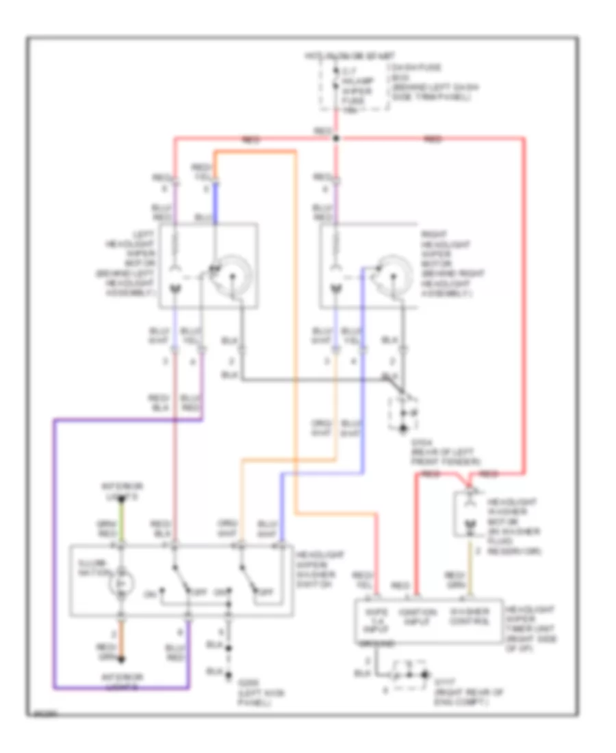 https://portal-diagnostov.com/license.html
Automotive Electricians Portal FZCO
Automotive Electricians Portal FZCO
https://portal-diagnostov.com/license.html
https://portal-diagnostov.com/license.html
Automotive Electricians Portal FZCO
Automotive Electricians Portal FZCOList of elements for Headlamp Wiper/Washer Wiring Diagram for Isuzu Trooper Limited 1995:
- C-7 h/lamp wiper fuse 10a
- Dash fuse box (behind left dash side trim panel)
- G104 (rear of left front fender)
- G117 (right rear of eng compt)
- G200 (left kick panel)
- Ground
- Headlight washer motor (in washer fluid reservoir)
- Headlight wiper timer unit (right side of i/p)
- Headlight wiper/ washer switch
- Hot in on or start
- Ignition input
- Illumi- nation
- Interior lights
- Left headlight wiper motor (behind left headlight assembly)
- Off
- Red
- Right headlight wiper motor (behind right headlight assembly)
- Washer control
- Wipe 1-4 input
Rear Wiper/Washer Wiring Diagram for Isuzu Trooper Limited 1995
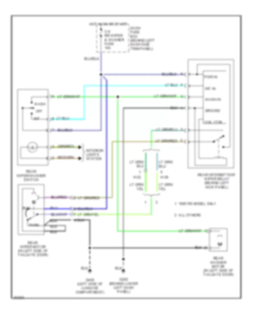 https://portal-diagnostov.com/license.html
Automotive Electricians Portal FZCO
Automotive Electricians Portal FZCO
https://portal-diagnostov.com/license.html
https://portal-diagnostov.com/license.html
Automotive Electricians Portal FZCO
Automotive Electricians Portal FZCOList of elements for Rear Wiper/Washer Wiring Diagram for Isuzu Trooper Limited 1995:
- 1995 rs model only
- All others
- C-6 rr wiper & washer fuse 10a
- Coil ctrl
- Dash fuse box (behind left dash side trim panel)
- G202 (behind lower left dash panel)
- G400 (left side of luggage compartment)
- Ground
- H-32
- H-38
- Hot in on or start
- Int
- Int in
- Interior lights system
- Off
- Park
- Pwr in
- Rear intermittent wiper relay (behind left kick panel)
- Rear washer motor (in left side of tailgate door)
- Rear wiper motor (in left side of tailgate door)
- Rear wiper/washer switch
- Run
- Wash
- Wash in

 Čeština
 Dansk
Dansk Deutsch
 Ελληνικά
 English
 English
 Español
 Suomi
Suomi Français
 Français
 עברית
עברית Hrvatski
 Magyar
 Italiano
 한국어
한국어 Nederlands
 Polski
 Português
 Português
 Română
 Русский
 Slovenčina
 Slovenščina
 Svenska
 Türkçe
 中文 (中国)
