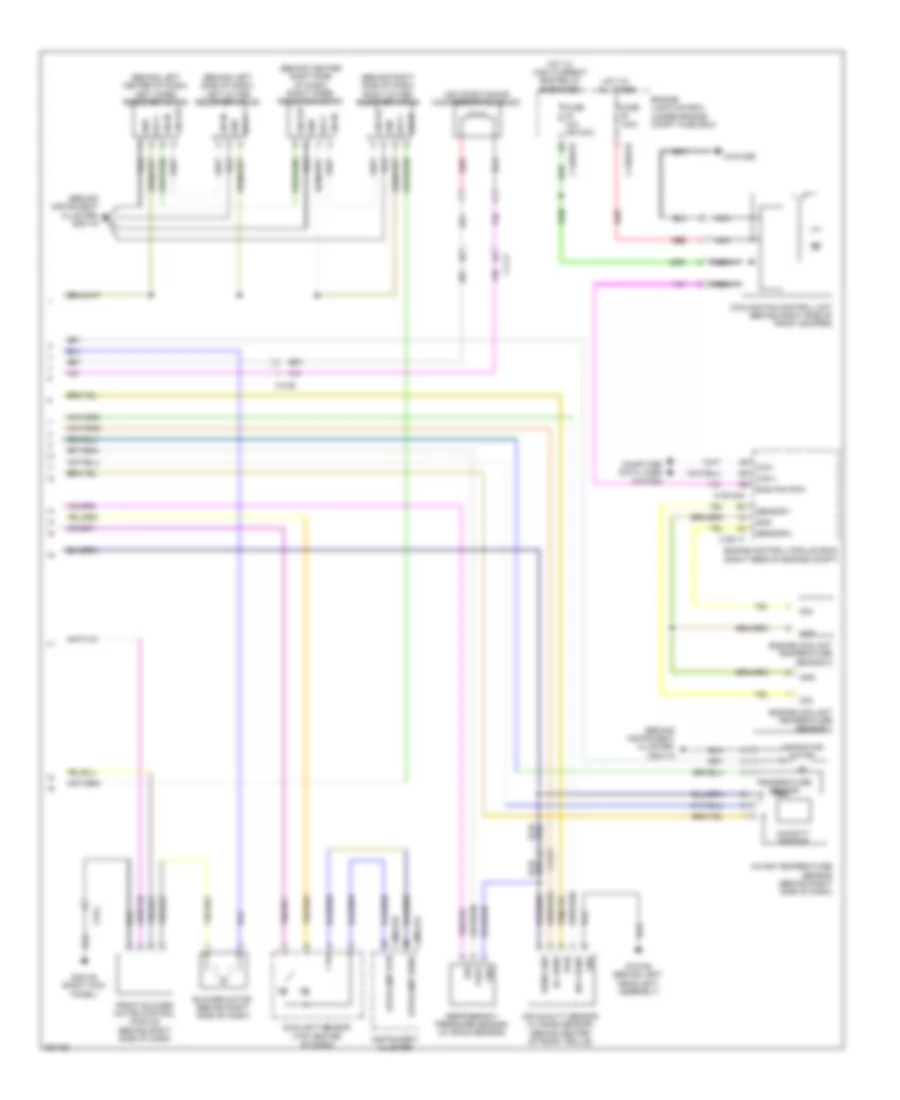
AIR CONDITIONING
Automatic A/C Wiring Diagram (1 of 2) for Jaguar XF 2011
 https://portal-diagnostov.com/license.html
Automotive Electricians Portal FZCO
Automotive Electricians Portal FZCO
https://portal-diagnostov.com/license.html
https://portal-diagnostov.com/license.html
Automotive Electricians Portal FZCO
Automotive Electricians Portal FZCO
List of elements for Automatic A/C Wiring Diagram (1 of 2) for Jaguar XF 2011:
- (behind instrument cluster) g2d115
- 5v sens
- Air intake +
- Air intake -
- Air intake fback
- Aspirator diag
- Battery junction box (right side of luggage compt)
- Blower ctrl
- Blower fback
- Blower motor relay
- C12-a
- C12-d
- C13-d
- C1bb01b
- C23-d
- C23-l
- C2h101a
- C2h101c
- C3bp01e
- C3bp01f
- C3bp01k
- C4bp01a
- C4bp01c
- C4bp01d
- Can +
- Can -
- Can in +
- Can in -
- Can out +
- Can out -
- Central junction box (right kick panel)
- Climate control module (top of right kick panel)
- Comp sol +
- Comp sol -
- Computer data lines system
- Evap sens
- Evaporator sensor (on hvac evaporator)
- Feet air distribution motor (behind center of dash)
- Fuse 10a
- Fuse 250a
- Fuse 30a
- G4d173 (right side of luggage compt)
- Gnd
- Gref sens gnd
- Hc in
- Hot at all times
- Humidity sens
- Hvac sens 5v
- Hvac sens gnd
- In car temp
- Internal electronics
- Left mode air mix motor (on left side of hvac)
- Lh solar sens
- Lin
- Lin gnd
- Lin pwr
- Lin pwr 2
- Nca
- Nox in
- Pressure sens
- Rear junction box (right side of luggage compt)
- Recirculated air motor (behind center of dash)
- Red
- Rh solar sens
- Right mode air mix motor (on right side of hvac)
- Screen air distribution door motor (behind center of dash)
- Sply
Automatic A/C Wiring Diagram (2 of 2) for Jaguar XF 2011
 https://portal-diagnostov.com/license.html
Automotive Electricians Portal FZCO
Automotive Electricians Portal FZCO
https://portal-diagnostov.com/license.html
https://portal-diagnostov.com/license.html
Automotive Electricians Portal FZCO
Automotive Electricians Portal FZCOList of elements for Automatic A/C Wiring Diagram (2 of 2) for Jaguar XF 2011:
- (behind center right side of dash) right inner register motor
- (behind instrument cluster) g2d115
- (behind left center of dash) left inner register motor
- (behind left side of dash) left outer register motor
- (behind right side of dash) right outer register motor
- Air conditioning compressor solenoid
- Air quality sensor (w/ smog sensor) (behind center of front grille)
- Aspirator motor
- Autolamp rtn
- Autolamp sens
- Blower motor (behind right side of dash)
- C11-p
- C12-a
- C12-b
- C1bb01b
- C1bb01e
- C1e117
- C1e120a
- C23-l
- C2mc01a
- C2mc01b
- Can +
- Can -
- Computer data lines system
- Cooling fan control unit (behind right side of front bumper)
- Engine control module (ecm) (right rear of engine compt)
- Engine coolant temperature sensor 1
- Engine coolant temperature sensor 2
- Engine junction box (under engine compt fuse box)
- Front blower motor control module (behind right side of dash)
- Fuse 100a
- Fuse 10a (or 30a)
- G1d129 (behind left headlight assembly)
- G1d132b
- G3d138 (right kick panel)
- Gnd
- Hc sens
- Hot at all times
- Hot w/ high current ems relay energized
- Humidity sensor
- In-car temperature sensor (behind right side of dash)
- Instrument cluster
- Lin in
- Lin out
- Nca
- Nox sens
- Pwr
- Rad fan pwm
- Red
- Refrigerant pressure sensor (w/ smog sensor)
- Sens gnd
- Sensor 1
- Sensor 2
- Sig
- Sply
- Sunlight sensor (top center of dash)
- Temperature sensor
- Vref
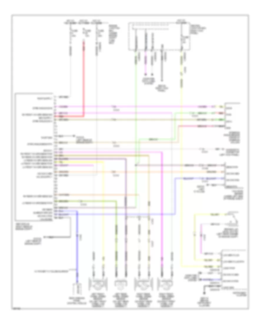
ANTI-LOCK BRAKES
Anti-lock Brakes Wiring Diagram for Jaguar XF 2011
 https://portal-diagnostov.com/license.html
Automotive Electricians Portal FZCO
Automotive Electricians Portal FZCO
https://portal-diagnostov.com/license.html
https://portal-diagnostov.com/license.html
Automotive Electricians Portal FZCO
Automotive Electricians Portal FZCOList of elements for Anti-lock Brakes Wiring Diagram for Jaguar XF 2011:
- Abs module (right rear of engine compt)
- Brake fluid level switch (left rear corner of engine compt)
- C12-a
- C12-b
- C13-b
- C13-c
- C1bb01b
- C23-d
- C2mc01a
- C2mc01b
- C3bp01d
- C3bp01f
- C3bp01j
- C3bp01k
- C44-p
- Central junction box (right kick panel)
- Computer data lines system
- Diagnostic connector (left kick panel)
- Engine junction box (under engine compt fuse box)
- Fuse 10a
- Fuse 25a
- Fuse 40a
- Fuse 5a
- G1d123 (left rear of engine compt)
- G2d115 (behind instrument cluster)
- G3d138 (right kick panel)
- G3d161 (left "c" pillar)
- Gnd
- Hot at all times
- Hs can 2 pos
- Hs can in pos
- Hs can pos
- Ign sens
- Instrument cluster
- Iso 9141
- Left front wheel speed sensor (on left front wheel hub assembly)
- Left rear wheel speed sensor (on left rear wheel hub assembly)
- Lh front wh spd sens pwr
- Lh front wh spd sens sig
- Lh rear wh spd sens pwr
- Lh rear wh spd sens sig
- Logic gnd
- Logic pwr
- Low brk fluid
- Low brk fluid rtn
- Ms can in pos
- Nca
- Pump gnd
- Pwr
- Red
- Rh front wh spd sens pwr
- Rh front wh spd sens sig
- Rh rear wh spd sens pwr
- Rh rear wh spd sens sig
- Right front wheel speed sensor (on right front wheel hub assembly)
- Right rear wheel speed sensor (on right rear wheel hub assembly)
- Roof opening panel control module
- Sens pwr
- Sens rtn
- Sig a
- Sig b
- Spd sw
- Steering angle sensor (inside of steering column)
- Strg angle sens rtn
- Strg angle sig a
- Strg angle sig b
- Sunroof spd sig
- Valve gnd
- W/ power tilt/slide sunroof
- Yaw rate sensor (under left side of parcel shelf)
ANTI-THEFT
Anti-theft Wiring Diagram (1 of 2) for Jaguar XF 2011
 https://portal-diagnostov.com/license.html
Automotive Electricians Portal FZCO
Automotive Electricians Portal FZCO
https://portal-diagnostov.com/license.html
https://portal-diagnostov.com/license.html
Automotive Electricians Portal FZCO
Automotive Electricians Portal FZCOList of elements for Anti-theft Wiring Diagram (1 of 2) for Jaguar XF 2011:
- (behind instrument cluster) g2d115
- (left end of dash) start control unit
- Ajar sw
- Anti theft
- Anti theft led
- Boot opn
- C13-a
- C23-d
- C23-r
- C2mc01a
- C2mc01b
- C37-a
- C3a-a
- C3b-a
- C3bp01e
- C3bp01f
- C3bp01g
- C3bp01h
- C3bp01j
- C3bp01k
- C3bp01l
- C44-a
- C4bp01d
- C4bp01f
- C4bp01k
- C4bp01l
- Can in pos
- Can pos
- Capw02a
- Capw02b
- Cbpw04a
- Cbpw04b
- Central junction box (right kick panel)
- Clu secu
- Computer data lines system
- Cruise control system
- Door ajar switch
- Driver door latch module (behind driver door trim)
- Driver door module (behind driver door trim)
- Fuse 5a
- G1d129 (behind left headlight assembly)
- G4d173 (right side of luggage compt)
- Gnd
- Gnd latch
- Hood ajar switch (behind left headlight assembly)
- Horn ctrl
- Horns system
- Hot at all times
- Incl pwr
- Incl rtn
- Instrument cluster
- L lin
- Latch gnd
- Left rear door latch module (behind left rear door trim)
- Left rear door module (behind left rear door trim)
- Lin
- Logic gnd
- Logic pwr
- Ms can pos
- Passenger door latch module (behind passenger door trim)
- Passenger door module (behind passenger door trim)
- Pwr gnd
- Rear junction box (right side of luggage compt)
- Scl gnd
- Scl pwr
- Security
- Security ind
- Security out
- Sounder passive
- Sply
- Sunlight sensor (top center of dash)
Anti-theft Wiring Diagram (2 of 2) for Jaguar XF 2011
 https://portal-diagnostov.com/license.html
Automotive Electricians Portal FZCO
Automotive Electricians Portal FZCO
https://portal-diagnostov.com/license.html
https://portal-diagnostov.com/license.html
Automotive Electricians Portal FZCO
Automotive Electricians Portal FZCOList of elements for Anti-theft Wiring Diagram (2 of 2) for Jaguar XF 2011:
- (behind right rear door trim)
- (left side of luggage compt) keyless vehicle module
- (right "c" pillar) g3d162
- (under front of center console) front center console antenna
- (under rear of center console) rear center console antenna
- Ant pos
- Battery backed sounder (left rear of engine compt)
- C11-b
- C12-b
- C13-a
- C13-d
- C1rt02a
- C1rt02b
- C23-a
- C38-a
- C3bp01d
- C3bp01e
- C3bp01f
- C3bp01k
- C3bp01l
- C44-a
- C44-c
- C49-a
- C4pk28a
- C4pk28b
- C4pk28d
- Can pos
- Central junction box (right kick panel)
- Computer data lines
- Computer data lines system
- Data
- Door ajar switch
- Fuse 5a
- G1d120 (right rear of engine compt)
- G3d138 (right kick panel)
- G4d171 (left side of luggage compt)
- Gnd
- Gnd rtn
- Hot at all times
- Idm lin
- Idm pwr
- Idm rtn
- Latch gnd
- Left rear internal antenna
- Liftgate latch/luggage compartment lid latch (luggage compartment lid latch: center rear of trunk lid)
- Lin
- Ms can in pos
- Ms can out pos
- Ms can pos
- Overhead console
- Passive sounder (left rear of engine compt)
- Pwr
- Radio frequency (rf) receiver
- Right rear door latch module
- Right rear door module (behind right rear door trim)
- Scl gnd
- Scl pwr
- Serial data
- Sns gnd
- Sns lin
- Sns pwr
- Steering column locking module (behind instrument cluster)
- System gnd
- Vbatt
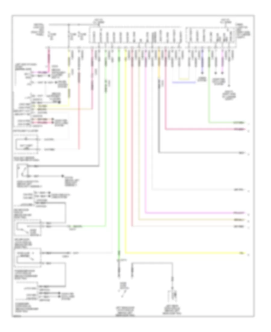
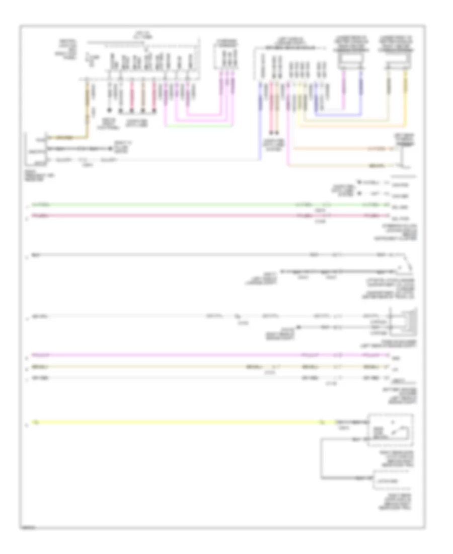
BODY CONTROL MODULES
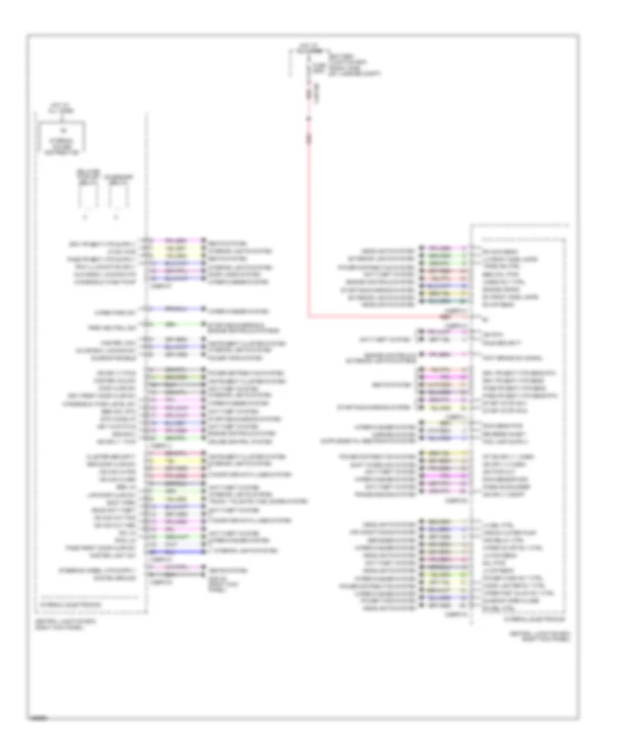
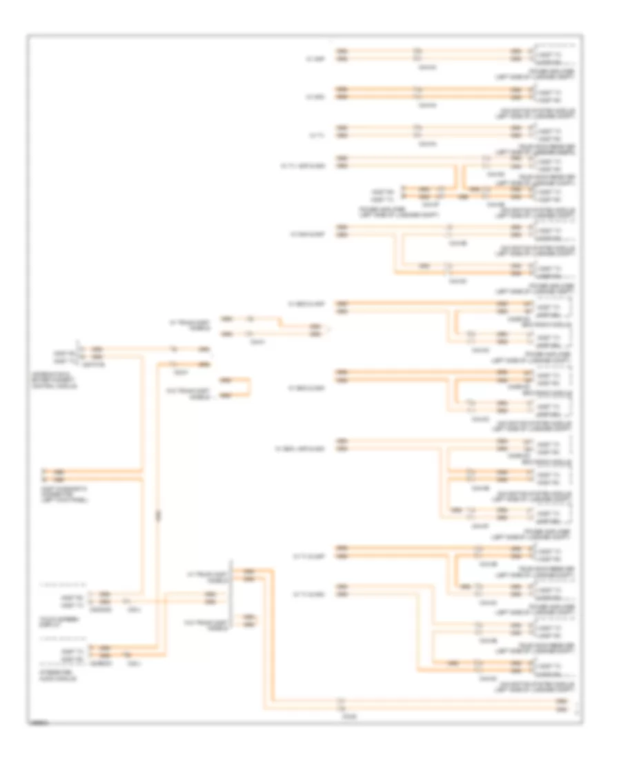
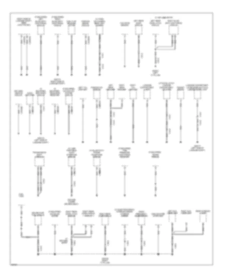
Central Junction Box Wiring Diagram for Jaguar XF 2011
 https://portal-diagnostov.com/license.html
Automotive Electricians Portal FZCO
Automotive Electricians Portal FZCO
https://portal-diagnostov.com/license.html
https://portal-diagnostov.com/license.html
Automotive Electricians Portal FZCO
Automotive Electricians Portal FZCOList of elements for Central Junction Box Wiring Diagram for Jaguar XF 2011:
- Accessory relay
- Air conditioning system
- Aircon water pump
- Anti-theft system
- Battery junction box (right side of luggage compt)
- Bbs incl pwr
- Bbs incl rtn
- Bbs lin
- Boot open
- C3bp01a
- C3bp01d
- C3bp01e
- C3bp01f
- C3bp01g
- C3bp01h
- C3bp01j
- C3bp01k
- C3bp01l
- C4bf10c
- Central junction box (right kick panel)
- Cigar lighter rly ctrl
- Cluster security
- Computer data lines system
- Cruise control system
- Defogger system
- Delayed pwr off relay
- Door locks system
- Driv fr seat htr sens
- Driv fr seat htr sens rtn
- Driv front door ajar sw
- Ems ewu
- Engine controls & exterior lights systems
- Engine controls system
- Engine crank
- Ets wake up
- Exterior lights system
- Foot brake sw signal
- Fpdb ign ctrl
- Fsjb security
- Fuse 250a
- G3d138 (right kick panel)
- Glove box locking mtr
- Glove box locking sw
- Headlights system
- Hfs relay ctrl
- Hood ajar sw
- Hot at all times
- Idm lin
- Idm pwr out
- Idm rtn
- Ign sply 1 fwd
- Ign sply 2 cabin
- Ign sply 2 ediff
- Ign sply 2 fwd
- Instrument cluster system
- Interior lights system
- Internal electronics
- Internal power distribution
- Key in status
- Lh dip beam
- Lh front side lamps
- Lh main beam
- Lh sbl ctrl
- Lhr door ajar sw
- Lp sw pwr
- Master light sw
- Master lock
- Master unlock
- Mirrors system
- Ms can in pos
- Ms can out pos
- Op ign sply 1 cabin
- Park neutral sig
- Pass fr seat htr sens
- Pass fr seat htr sens rtn
- Pass front door ajar sw
- Passive sounder
- Power distribution system
- Power tops system
- Power wash rly ctrl
- Pwm illumination sply
- Rain lin
- Rain sens pwr
- Rain sensor gnd
- Red
- Reverse inhibit
- Rh dip beam
- Rh front side lamps
- Rh main beam
- Rh sbl ctrl
- Rhr door ajar sw
- Rsjb anti theft
- Scl pwr
- Seats system
- Shift interlock system
- Start stop sw1
- Start stop sw2
- Starting/charging & engine controls systems
- Starting/charging system
- Sunroof enable
- Sunroof open close
- System ground
- Transmissions system
- Trunk, tailgate, fuel doors system
- Uhego rly ctrl
- Windshield wash level sw
- Windshield wash pump
- Wiper fast slow rly ctrl
- Wiper on off rly ctrl
- Wiper park sw
- Wiper/washer system
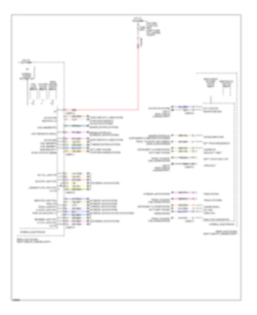
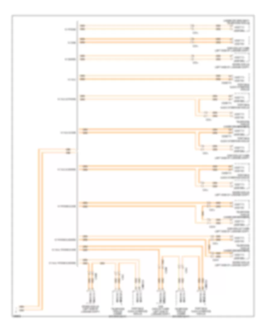
Rear Junction Box Wiring Diagram for Jaguar XF 2011
 https://portal-diagnostov.com/license.html
Automotive Electricians Portal FZCO
Automotive Electricians Portal FZCO
https://portal-diagnostov.com/license.html
https://portal-diagnostov.com/license.html
Automotive Electricians Portal FZCO
Automotive Electricians Portal FZCOList of elements for Rear Junction Box Wiring Diagram for Jaguar XF 2011:
- Air bag deployed
- Anti-theft system
- Battery junction box (right side of luggage compt)
- Blower motor relay
- Bms rvpa lin
- C4bf10b
- C4bp01a
- C4bp01d
- C4bp01f
- C4bp01g
- C4bp01h
- C4bp01k
- C4bp01l
- Computer data lines system
- Di ctr
- Engine controls & exterior lights systems
- Engine controls system
- Ext trunk release sw
- Exterior lights & navigation systems
- Exterior lights system
- Fade control
- Foot brake sw signal
- Fsjb anti theft
- Fuel flap locking mtr
- Fuel pump relay
- Fuel sender a
- Fuel sender b
- Fuel sender rtn
- Fuse 250a
- G4d173 (right side of luggage compt)
- Hazard signal
- Hazard sw
- Hmsl ctr
- Horn ctrl
- Horns system
- Hot at all times
- Instrument cluster system
- Interior lights system
- Internal electronics
- Internal power distribution
- Lh stop lamp ctrl
- Lh tail lamp ctrl
- License plate lamp ctrl
- Lppr input
- Ms can pos
- Nav vics pwr
- Navigation system
- Rear aircon blower motor relay
- Rear fog lamp ctrl
- Rear heated window relay
- Rear junction box (right side of luggage compt)
- Red
- Restraints ignition relay
- Reverse lamp ctrl
- Rh stop lamp ctrl
- Rh tail lamp ctr
- Rsjb power gnd
- Rsjb security
- Scl gnd
- Soft touch fuel flap
- Start stop sw sense
- Starting/charging & navigation systems
- Starting/charging system
- Trunk lamps pw
- Trunk mtr open
- Trunk, tailgate, fuel doors & door locks systems
- Trunk, tailgate, fuel doors system
COMPUTER DATA LINES
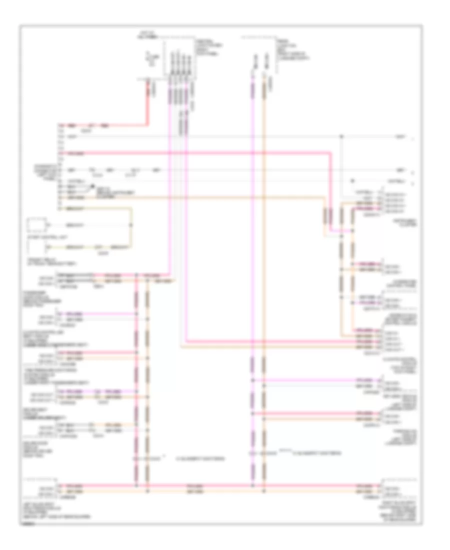
Diagnostic Socket Wiring Diagram (1 of 2) for Jaguar XF 2011
 https://portal-diagnostov.com/license.html
Automotive Electricians Portal FZCO
Automotive Electricians Portal FZCO
https://portal-diagnostov.com/license.html
https://portal-diagnostov.com/license.html
Automotive Electricians Portal FZCO
Automotive Electricians Portal FZCOList of elements for Diagnostic Socket Wiring Diagram (1 of 2) for Jaguar XF 2011:
- C11-p
- C12-a
- C23-d
- C23-r
- C2h101a
- C2mc01a
- C2mt01a
- C33-d
- C3a-a
- C3b-a
- C3bp01f
- C3bp01k
- C3hs03c
- C3mc39b
- C3pso28
- C44-s
- C4bp01l
- C4mp01a
- C4pk28d
- C4rb02a
- C4rb02b
- Can in +
- Can in -
- Can out +
- Can out -
- Capwo28
- Cbpw04b
- Central junction box (right kick panel)
- Climate control module (top of right kick panel)
- Climate controlled seat module (if equipped) (under front passenger's seat)
- Diagnostic connector (left kick panel)
- Driver door module (behind driver door trim)
- Driver seat module (under driver's seat)
- Fuse 5a
- G2d115 (behind instrument cluster)
- Hot at all times
- Hs can in +
- Hs can in -
- Information & entertainment control module
- Instrument cluster
- Integrated control panel
- Keyless vehicle module (left side of luggage compt)
- Left blind spot monitoring module (if equipped) (behind left side of rear bumper)
- Ms can +
- Ms can -
- Ms can in +
- Ms can in -
- Ms can out +
- Ms can out -
- Parking aid module (left side of luggage compt)
- Passenger door module (behind passenger door trim)
- Rear junction box (right side of luggage compt)
- Red
- Right blind spot monitoring module (if equipped) (behind right side of rear bumper)
- Start control unit
- Tire pressure monitoring system module (if equipped) (under front passenger's seat)
- Transit relay (in trunk, near battery)
- W/ blindspot monitoring
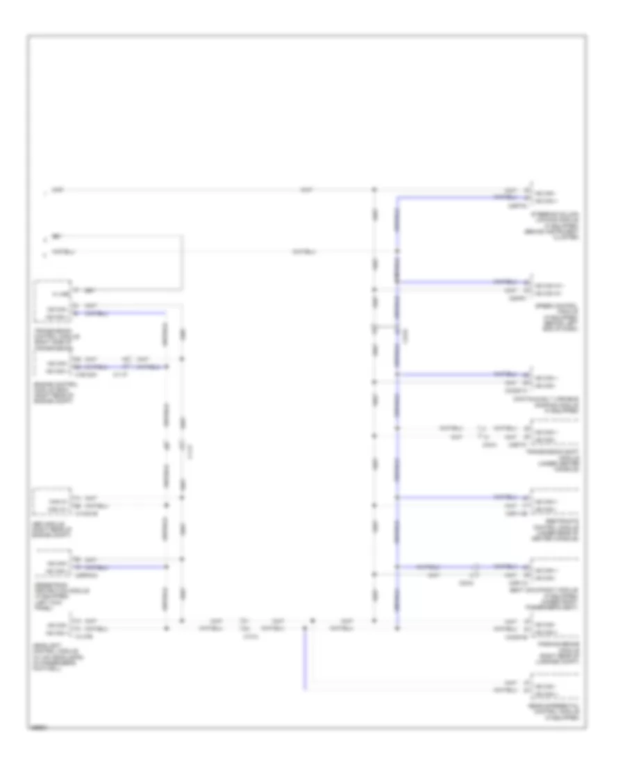
Diagnostic Socket Wiring Diagram (2 of 2) for Jaguar XF 2011
 https://portal-diagnostov.com/license.html
Automotive Electricians Portal FZCO
Automotive Electricians Portal FZCO
https://portal-diagnostov.com/license.html
https://portal-diagnostov.com/license.html
Automotive Electricians Portal FZCO
Automotive Electricians Portal FZCOList of elements for Diagnostic Socket Wiring Diagram (2 of 2) for Jaguar XF 2011:
- Abs module (right rear of engine compt)
- C11-p
- C13-a
- C1ca01b
- C1e120a
- C1lf39
- C23-r
- C2mf01
- C2rp03a
- C2rt03
- C33-c
- C33-g
- C3cd01a
- C3et37
- C3r114b
- C3r118
- C4c801b
- Can in +
- Can in -
- Continuously variable damping module (if equipped)
- Engine control module (ecm) (right rear of engine compt)
- Headlight control module (w/ hid headlamps) (in passenger's footwell)
- Hs can +
- Hs can -
- Hs can in +
- Hs can in -
- K line
- Parking brake module (right rear of luggage compt)
- Pedestrian protection module (if equipped) (left kick panel)
- Rear differential control module (if equipped)
- Restraints control module (under rear of center console)
- Seat occupancy module (if equipped) (under front passenger's seat)
- Speed control module (if equipped) (behind left end of dash)
- Steering column locking module (if equipped) (behind instrument cluster)
- Transmission control module (right side of transmission)
- Transmission shift module (under center console)
Fibre Optic Network Wiring Diagram (1 of 2) for Jaguar XF 2011
 https://portal-diagnostov.com/license.html
Automotive Electricians Portal FZCO
Automotive Electricians Portal FZCO
https://portal-diagnostov.com/license.html
https://portal-diagnostov.com/license.html
Automotive Electricians Portal FZCO
Automotive Electricians Portal FZCOList of elements for Fibre Optic Network Wiring Diagram (1 of 2) for Jaguar XF 2011:
- C23-h
- C23-j
- C2mc02c
- C2me03c
- C2mt01b
- C33-b
- C44-aa
- C44-ab
- C44-ac
- C44-ad
- C44-ae
- C44-af
- C44-h
- C4me18a
- Iboc radio module
- Information & entertainment control module
- Integrated audio module
- Most diagnostic connector (left kick panel)
- Most rx
- Most tx
- Navigation system module (left side of luggage compt)
- Power amplifier (left side of luggage compt)
- Television receiver (left side of luggage compt)
- Touch screen display
- W/ amp
- W/ iboc & amp
- W/ iboc & mmm
- W/ iboc, amp & mmm
- W/ mmm
- W/ mmm & amp
- W/ trunk most models
- W/ tv
- W/ tv & amp
- W/ tv & mmm
- W/ tv, amp & mmm
- W/o trunk most models
Fibre Optic Network Wiring Diagram (2 of 2) for Jaguar XF 2011
 https://portal-diagnostov.com/license.html
Automotive Electricians Portal FZCO
Automotive Electricians Portal FZCO
https://portal-diagnostov.com/license.html
https://portal-diagnostov.com/license.html
Automotive Electricians Portal FZCO
Automotive Electricians Portal FZCOList of elements for Fibre Optic Network Wiring Diagram (2 of 2) for Jaguar XF 2011:
- (under driver's seat) telephone module
- C33-l
- C33-m
- C3me17a
- Dab module tuner (left side of luggage compt)
- Most-rx
- Most-tx
- Portable audio interface module
- Sdars module (left side of luggage compt)
- Telephone module (under driver's seat)
- W/ auu
- W/ auu & dab
- W/ auu & phone
- W/ auu & sdars
- W/ auu, phone & dab
- W/ auu, phone & sdars
- W/ dab
- W/ phone
- W/ phone & dab
- W/ phone & sdars
- W/ sdars
COOLING FAN
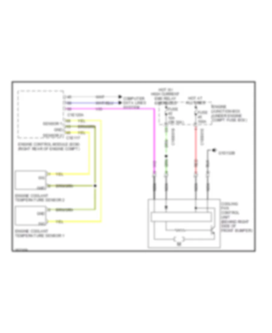
Cooling Fan Wiring Diagram for Jaguar XF 2011
 https://portal-diagnostov.com/license.html
Automotive Electricians Portal FZCO
Automotive Electricians Portal FZCO
https://portal-diagnostov.com/license.html
https://portal-diagnostov.com/license.html
Automotive Electricians Portal FZCO
Automotive Electricians Portal FZCOList of elements for Cooling Fan Wiring Diagram for Jaguar XF 2011:
- C1bb01b
- C1bb01e
- C1e120a
- Computer data lines system
- Cooling fan control unit (behind right side of front bumper)
- Engine control module (ecm) (right rear of engine compt)
- Engine coolant temperature sensor 1
- Engine coolant temperature sensor 2
- Engine junction box (under engine compt fuse box)
- Fuse 100a
- Fuse 10a (or 30a)
- G1d132b
- Gnd
- Hot at all times
- Hot w/ high current ems relay energized
- Nca
- Red
- Sensor 1
- Sensor 2 c1e117
- Sig
CRUISE CONTROL
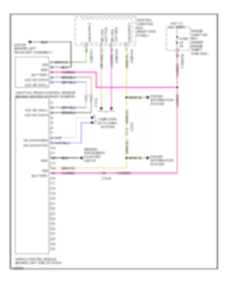
Cruise Control Wiring Diagram, with Adaptive Cruise Control for Jaguar XF 2011
 https://portal-diagnostov.com/license.html
Automotive Electricians Portal FZCO
Automotive Electricians Portal FZCO
https://portal-diagnostov.com/license.html
https://portal-diagnostov.com/license.html
Automotive Electricians Portal FZCO
Automotive Electricians Portal FZCOList of elements for Cruise Control Wiring Diagram, with Adaptive Cruise Control for Jaguar XF 2011:
- (behind instrument cluster) g2d115
- Acc hs can h
- Acc hs can l
- Adaptive speed control sensor (behind center of front bumper)
- Battery
- C12-b
- C1bb01b
- C23-d
- C3bp01e
- C3bp01j
- C3bp01k
- Central junction box (right kick panel)
- Computer data lines system
- Engine junction box (under engine compt fuse box)
- Fuse 5a
- G1d129 (behind left headlight assembly)
- Gnd
- Hot at all times
- Hs can in pos
- Ign
- Ms can out pos
- Power distribution system
- Speed control module (behind left end of dash)
Cruise Control Wiring Diagram, without Adaptive Cruise Control for Jaguar XF 2011
 https://portal-diagnostov.com/license.html
Automotive Electricians Portal FZCO
Automotive Electricians Portal FZCO
https://portal-diagnostov.com/license.html
https://portal-diagnostov.com/license.html
Automotive Electricians Portal FZCO
Automotive Electricians Portal FZCOList of elements for Cruise Control Wiring Diagram, without Adaptive Cruise Control for Jaguar XF 2011:
- (top of brake pedal bracket assembly) brake pedal switch
- 5v ref +
- Accelerator pedal position sensor (top of accelerator pedal bracket)
- Ap 5v
- Ap1
- Ap2
- Ap2-
- Brake sw
- Brake sw 2
- C13-d
- C1bb01b
- C1e117
- C1e120a
- C23-d
- C2mc01a
- C2r115a
- C3bp01e
- C3bp01f
- Can
- Cancel
- Central junction box (right kick panel)
- Clock spring (in steering column)
- Computer data lines system
- Cruise deactivation switch
- Cruise sig
- Cruise sw gnd
- Decel
- Electric throttle unit
- Engine control module (ecm) (right rear of engine compt)
- Engine controls system
- Engine junction box (under engine compt fuse box)
- Exterior lights system
- Foot brake switch
- Fuse 10a
- Fuse 5a
- G1d108 (behind right front wheel arch liner)
- G1d120 (right rear of engine compt)
- G2d115 (behind instrument cluster)
- Gnd
- Head+
- Head-
- Headway (+)
- Headway (-)
- Hot at all times
- Hs can in pos
- Hs can pos
- Ice remote switch
- Ign in
- Illum out 1
- Instrument cluster
- Lin
- Power distribution system
- Pwr gnd 1
- Pwr gnd 2
- Remote cruise controls
- Res
- Resume
- Sa004
- Sens gnd 2
- Set+
- Set-
- Set/ accel
- Start control unit (left end of dash)
- Sw002
- Sw003
- Sw004
- Throttle mtr +
- Throttle mtr -
- Throttle position sens 1
- Throttle position sens 2
DEFOGGERS
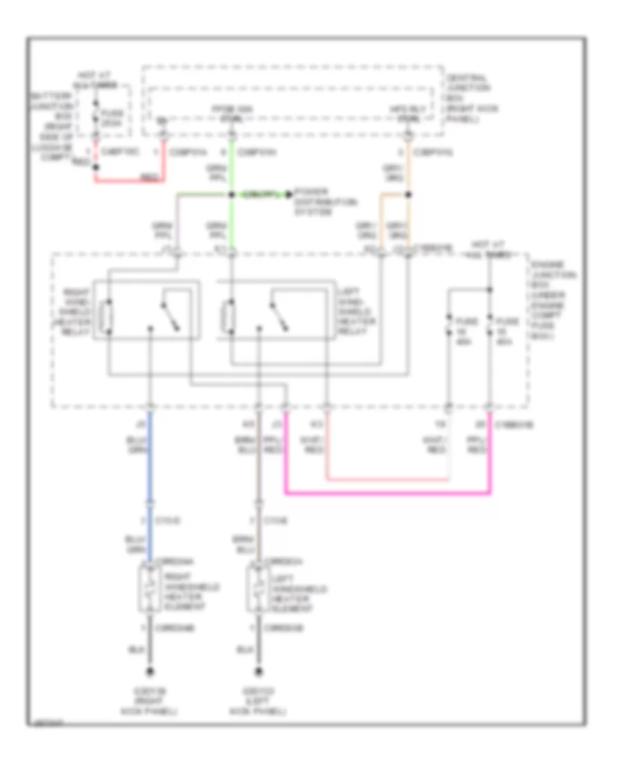
Heated Windshield Wiring Diagram for Jaguar XF 2011
 https://portal-diagnostov.com/license.html
Automotive Electricians Portal FZCO
Automotive Electricians Portal FZCO
https://portal-diagnostov.com/license.html
https://portal-diagnostov.com/license.html
Automotive Electricians Portal FZCO
Automotive Electricians Portal FZCOList of elements for Heated Windshield Wiring Diagram for Jaguar XF 2011:
- Battery junction box (right side of luggage compt)
- C13-d
- C13-e
- C1bb01b
- C3bp01a
- C3bp01g
- C3bp01h
- C4bf10c
- C9rd03a
- C9rd03b
- C9rd04a
- C9rd04b
- Central junction box (right kick panel)
- Engine junction box (under engine compt fuse box)
- Fpdb ign ctrl
- Fuse 250a
- Fuse 40a
- G3d133 (left kick panel)
- G3d138 (right kick panel)
- Hfs rly ctrl
- Hot at all times
- Left wind- shield heater relay
- Left windshield heater element
- Power distribution system
- Red
- Right wind- shield heater relay
- Right windshield heater element
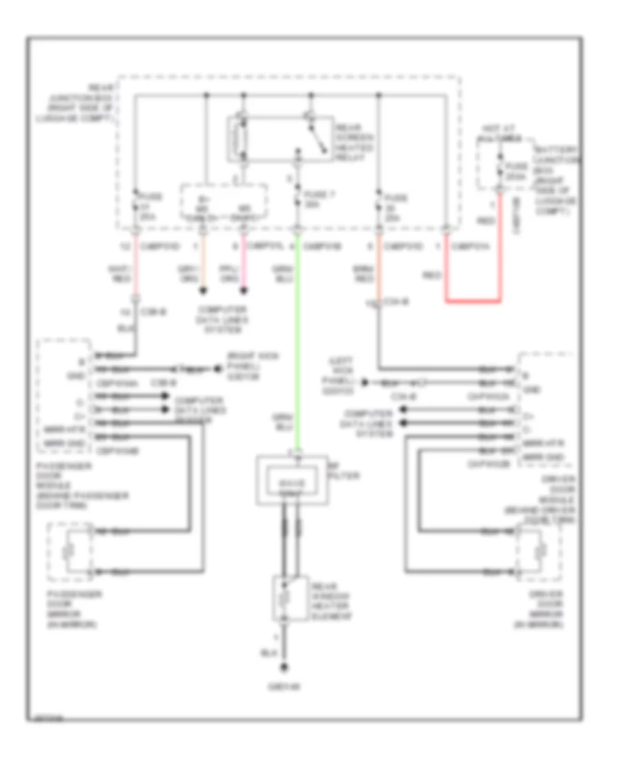
Rear Defogger & Heated Mirrors Wiring Diagram for Jaguar XF 2011
 https://portal-diagnostov.com/license.html
Automotive Electricians Portal FZCO
Automotive Electricians Portal FZCO
https://portal-diagnostov.com/license.html
https://portal-diagnostov.com/license.html
Automotive Electricians Portal FZCO
Automotive Electricians Portal FZCOList of elements for Rear Defogger & Heated Mirrors Wiring Diagram for Jaguar XF 2011:
- (left kick panel) g3d133
- (right kick panel) g3d138
- B+ ms can c+
- Battery junction box (right side of luggage compt)
- C3a-b
- C3b-b
- C4bf10b
- C4bp01a
- C4bp01b
- C4bp01d
- C4bp01l
- Capw02a
- Capw02b
- Cbpw04a
- Cbpw04b
- Computer data lines system
- Driver door mirror (in mirror)
- Driver door module (behind driver door trim)
- Fuse 250a
- Fuse 25a
- Fuse 7 30a
- G9d149
- Gnd
- Hot at all times
- Mirr gnd
- Mirr htr
- Ms can c-
- Nca
- Passenger door mirror (in mirror)
- Passenger door module (behind passenger door trim)
- Rear junction box (right side of luggage compt)
- Rear screen heated relay
- Rear window heater element
- Red
- Rf filter
- Wave trap
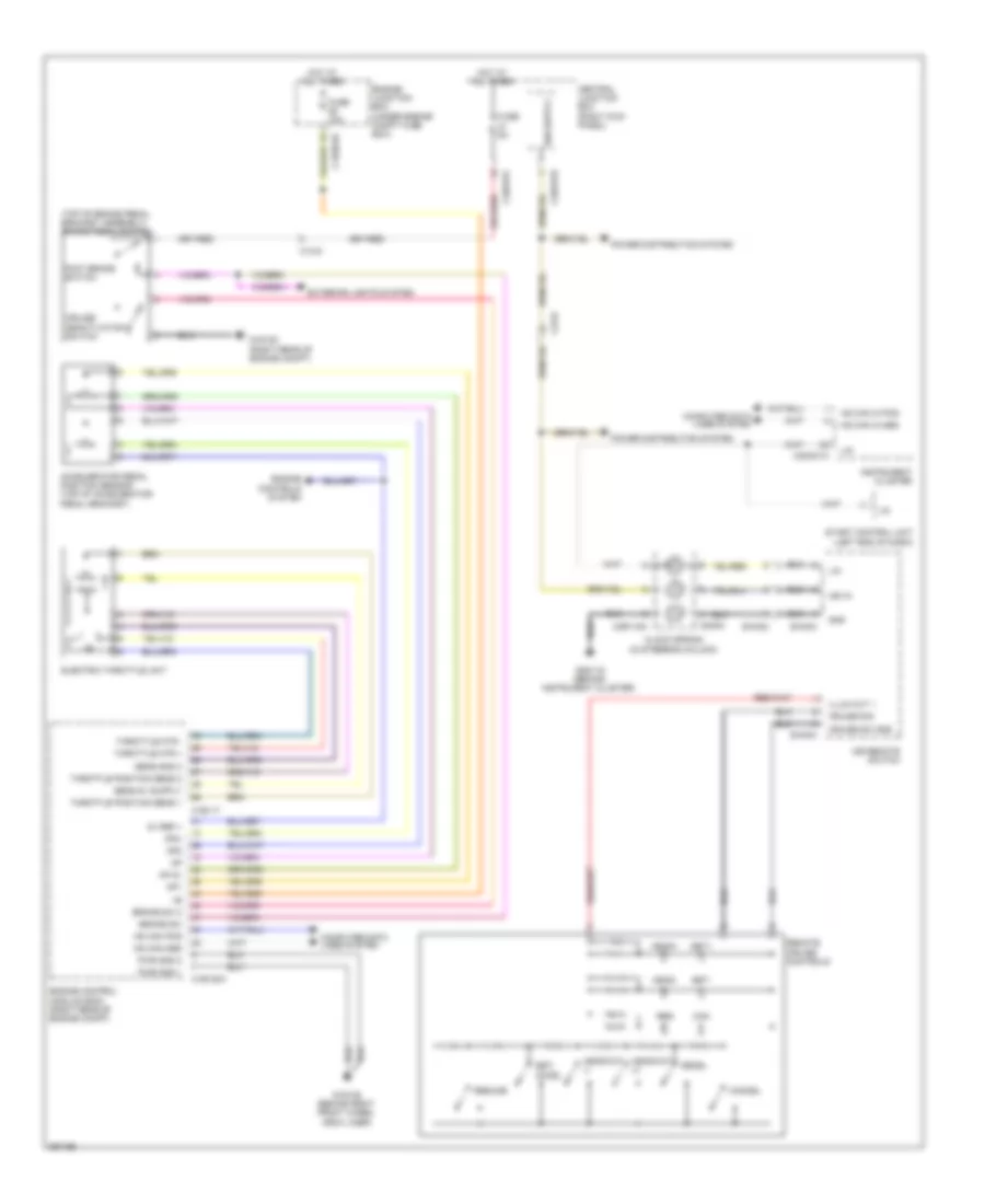
ELECTRONIC POWER STEERING
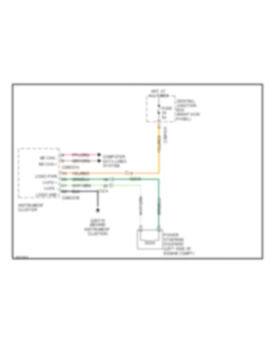
Electronic Power Steering Wiring Diagram for Jaguar XF 2011
 https://portal-diagnostov.com/license.html
Automotive Electricians Portal FZCO
Automotive Electricians Portal FZCO
https://portal-diagnostov.com/license.html
https://portal-diagnostov.com/license.html
Automotive Electricians Portal FZCO
Automotive Electricians Portal FZCOList of elements for Electronic Power Steering Wiring Diagram for Jaguar XF 2011:
- C12-a
- C23-d
- C2mc01a
- C2mc01b
- C3bp01f
- Central junction box (right kick panel)
- Computer data lines system
- Fuse 5a
- G2d115 (behind instrument cluster)
- Hot at all times
- Instrument cluster
- Logic gnd
- Logic pwr
- Ms can +
- Ms can -
- Power steering solenoid (left side of engine compt)
- Vaps +
- Vaps -
ELECTRONIC SUSPENSION
Electronic Suspension Wiring Diagram for Jaguar XF 2011
 https://portal-diagnostov.com/license.html
Automotive Electricians Portal FZCO
Automotive Electricians Portal FZCO
https://portal-diagnostov.com/license.html
https://portal-diagnostov.com/license.html
Automotive Electricians Portal FZCO
Automotive Electricians Portal FZCOList of elements for Electronic Suspension Wiring Diagram for Jaguar XF 2011:
- (on left rear shock) left rear damper solenoid
- Adaptive damping module (if equipped) (under front passenger's seat)
- B batt
- Battery junction box (right side of luggage compt)
- C+ hs can pos
- C+ ms can in pos
- C+ ms can out pos
- C13-a
- C13-b
- C13-d
- C3bp01a
- C3bp01d
- C3bp01f
- C3bp01k
- C3cd01a
- C3cd01b
- C44-r
- C4bf10c
- Central junction box (right kick panel)
- Computer data lines system
- Delayed pwr off relay (pcb relay)
- Fuse 10a
- Fuse 250a
- G3d138 (right kick panel)
- G3d183b (under front passenger's seat)
- Gnd
- Gref sens gnd 1
- Gref sens gnd 2
- Hot at all times
- Internal electronics
- Ip po fl sig
- Ip po fr sig
- Ip po rl sig
- Ip po rr sig
- Ip va fl sig
- Ip va fr sig
- Ip va rl sig
- Left front accelerometer
- Left front damper solenoid (on left front shock)
- Left front height sensor
- Left rear height sensor
- Nca
- Op fl damper pos
- Op fr damper pos
- Op rl damper pos
- Op rr damper pos
- P gnd
- P system gnd
- Rear accelerometer (left rear of luggage compt)
- Red
- Right front accelerometer (behind right front wheel arch liner)
- Right front damper solenoid (on right front shock)
- Right front height sensor (in right front wheelwell)
- Right rear damper solenoid (on right rear shock)
- Right rear height sensor (in right rear wheelwell)
- Sens 1 gnd
- Sens 1 out
- Sens 1 sply
- Sens sply
- Va sig
- Vref sens sply 1
- Vref sens sply 2
ENGINE PERFORMANCE
5.0L
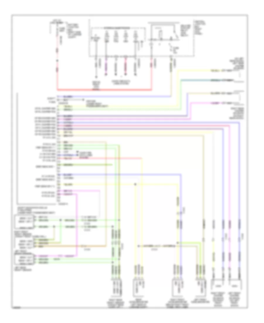
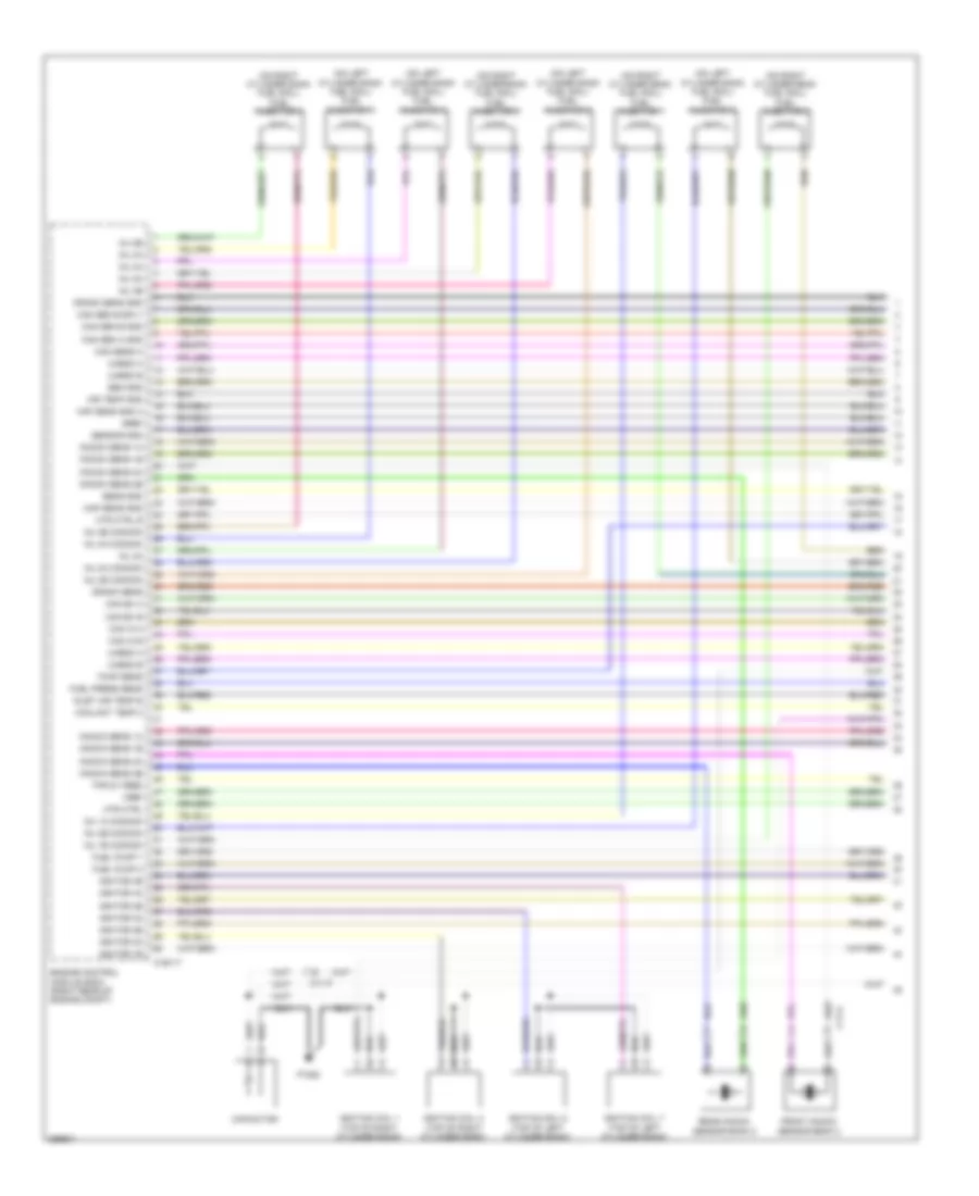
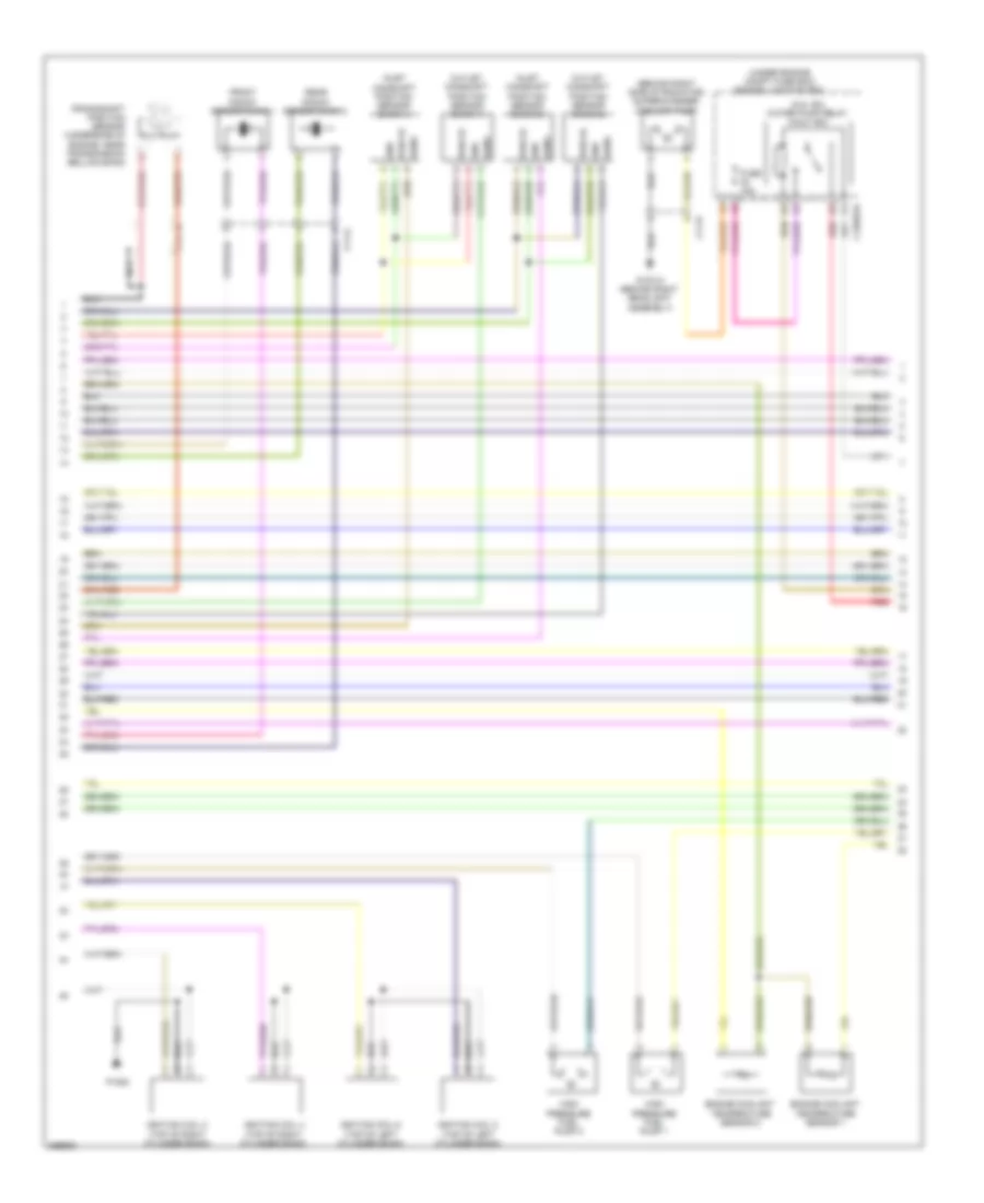
5.0L, Engine Performance Wiring Diagram (1 of 6) for Jaguar XF 2011
 https://portal-diagnostov.com/license.html
Automotive Electricians Portal FZCO
Automotive Electricians Portal FZCO
https://portal-diagnostov.com/license.html
https://portal-diagnostov.com/license.html
Automotive Electricians Portal FZCO
Automotive Electricians Portal FZCOList of elements for 5.0L, Engine Performance Wiring Diagram (1 of 6) for Jaguar XF 2011:
- (on left cylinder bank fuel rail) fuel injector 5
- (on left cylinder bank fuel rail) fuel injector 6
- (on left cylinder bank fuel rail) fuel injector 7
- (on left cylinder bank fuel rail) fuel injector 8
- (on right cylinder bank fuel rail) fuel injector 1
- (on right cylinder bank fuel rail) fuel injector 2
- (on right cylinder bank fuel rail) fuel injector 3
- (on right cylinder bank fuel rail) fuel injector 4
- Air temp gnd
- C11-a
- C11-p
- C1e117
- Cam ex a
- Cam ex b
- Cam in a
- Cam in b
- Cam sen a gnd
- Cam sen b gnd
- Cam sen b sply
- Cam sens a
- Capacitor
- Coolant temp 2
- Crank sens
- Crank sens gnd
- Engine control module (ecm) (right rear of engine compt)
- Front knock sensor bank 2
- Fuel press sens
- Fuel pump 1
- Fuel pump 2
- Gref
- Htr ctrl
- Htr ctrl b
- Ignition coil 1 (top of right cylinder bank)
- Ignition coil 3 (top of right cylinder bank)
- Ignition coil 5 (top of left cylinder bank)
- Ignition coil 7 (top of left cylinder bank)
- Ignitor 1b
- Ignitor 2a
- Ignitor 2b
- Ignitor 3a
- Ignitor 3b
- Ignitor 4a
- Ignitor 4b
- Inj 1a commom
- Inj 1b commom
- Inj 2a
- Inj 2a commom
- Inj 2b
- Inj 2b common
- Inj 3a
- Inj 3b common
- Inj 4a
- Inj 4a common
- Inj 4b
- Inj 4b common
- Inlet air temp b
- Knock sens 1a
- Knock sens 1b
- Knock sens 2a
- Knock sens 2b
- Maf sens gnd a
- Map sens gnd
- P1080
- Rear knock sensor bank 2
- Sen gnd
- Sens gnd
- Sensor gnd
- Tmap sens
- Tps 5v feed
- Uhego a
- Uhego b
- Vref
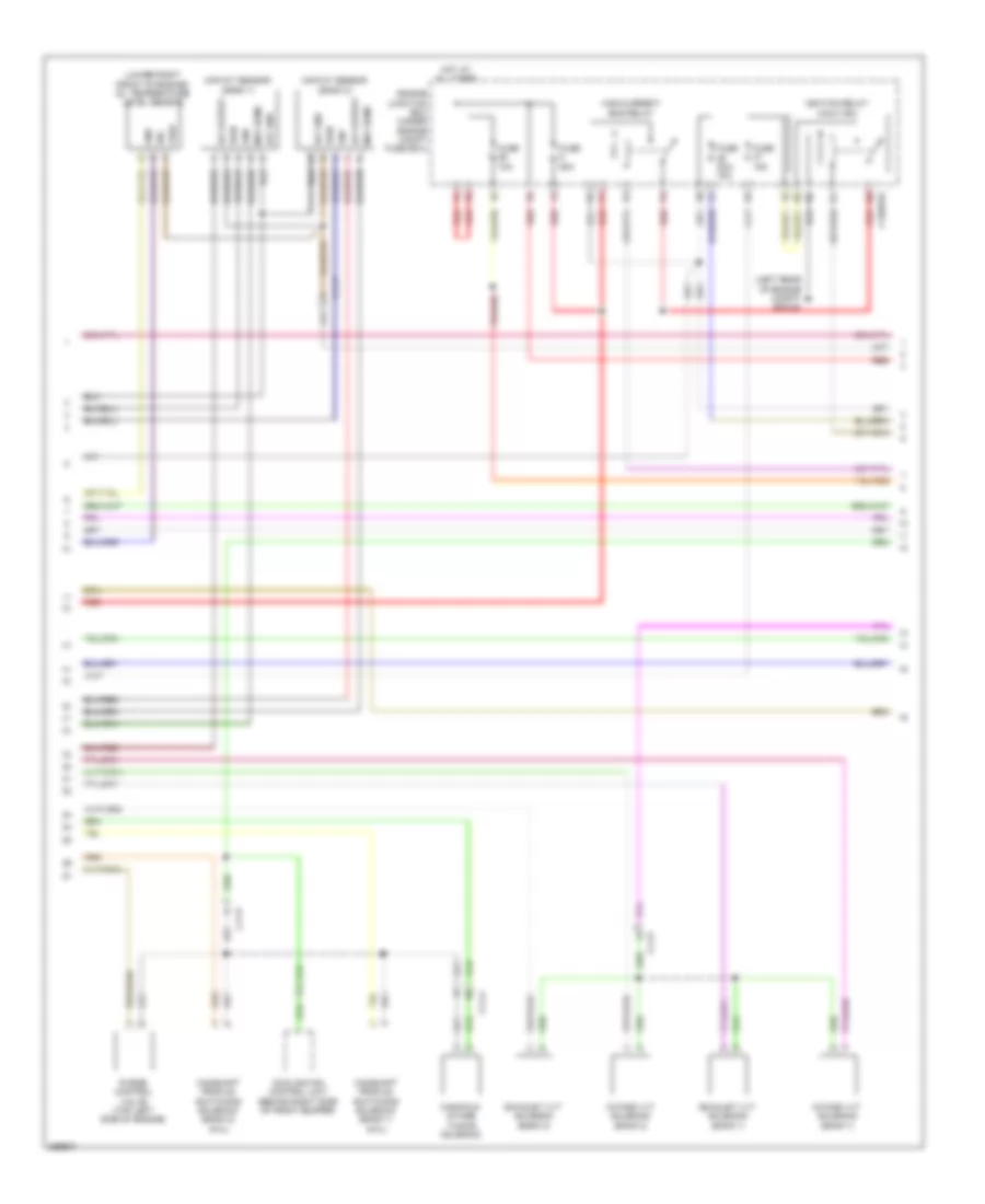
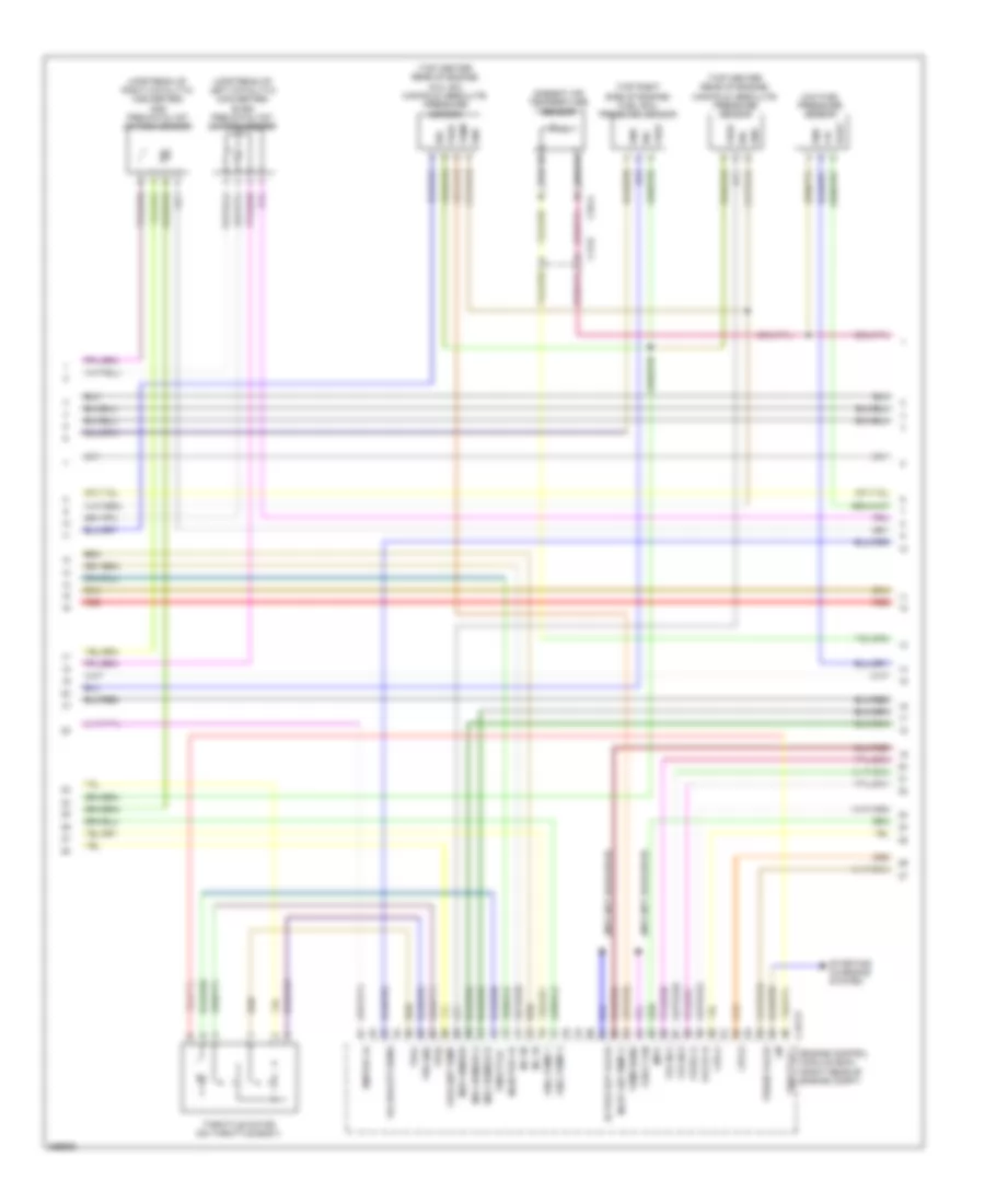
5.0L, Engine Performance Wiring Diagram (2 of 6) for Jaguar XF 2011
 https://portal-diagnostov.com/license.html
Automotive Electricians Portal FZCO
Automotive Electricians Portal FZCO
https://portal-diagnostov.com/license.html
https://portal-diagnostov.com/license.html
Automotive Electricians Portal FZCO
Automotive Electricians Portal FZCOList of elements for 5.0L, Engine Performance Wiring Diagram (2 of 6) for Jaguar XF 2011:
- (5.0l sc) water pump relay (half iso)
- (behind right side of radiator) supercharger coolant pump
- (under engine compt fuse box) engine junction box
- C11-a
- C11-r
- C1bb01b
- Crankshaft position sensor (underside of engine, near transmission bellhousing)
- Engine coolant temperature sensor 1
- Engine coolant temperature sensor 2
- Front knock sensor bank 1
- Fuse 15a
- G1d131 (behind right headlight assembly)
- Gnd
- High pressure fuel pump 1
- High pressure fuel pump 2
- Ignition coil 2 (top of right cylinder bank)
- Ignition coil 4 (top of right cylinder bank)
- Ignition coil 6 (top of left cylinder bank)
- Ignition coil 8 (top of left cylinder bank)
- Inlet camshaft position sensor (bank 1)
- Inlet camshaft position sensor (bank 2)
- Nca
- Outlet camshaft position sensor (bank 1)
- Outlet camshaft position sensor (bank 2)
- P1080
- Pwr 5v
- Rear knock sensor bank 2
- Red
- Sens
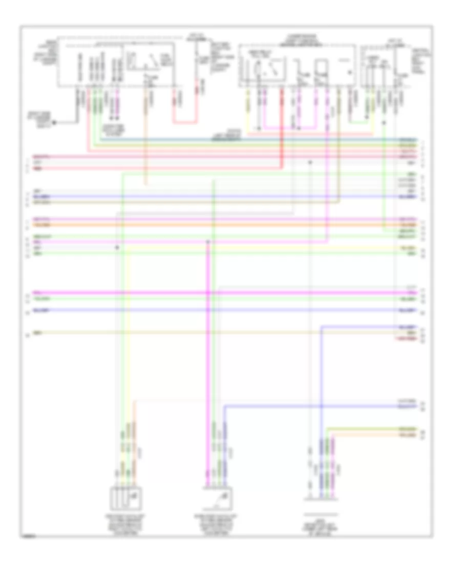
5.0L, Engine Performance Wiring Diagram (3 of 6) for Jaguar XF 2011
 https://portal-diagnostov.com/license.html
Automotive Electricians Portal FZCO
Automotive Electricians Portal FZCO
https://portal-diagnostov.com/license.html
https://portal-diagnostov.com/license.html
Automotive Electricians Portal FZCO
Automotive Electricians Portal FZCOList of elements for 5.0L, Engine Performance Wiring Diagram (3 of 6) for Jaguar XF 2011:
- (info not available)
- (top center rear of engine) (5.0l sc) manifold absolute pressure sensor
- (top center rear of engine) manifold absolute pressure sensor
- (top right side of engine) fuel rail pressure sensor
- (upstream of left catalytic converter) even pre-catalyst oxygen sensor
- (upstream of right catalytic converter) odd pre-catalyst oxygen sensor
- +5v
- Active ext valve
- Ambient air temperature sensor
- C13-e
- C1e117
- C3a-a
- Coolant temp
- Cps a
- Cps b
- E box fan
- Engine control module (ecm) (right rear of engine compt)
- Fuel pump 1
- Fuel pump 2
- Gnd
- Ignitor 1a
- Imtv
- Inj 1b
- Inj 3b
- Injector 1a
- Inlet air temp a
- Lin
- Low fuel pressure sensor
- Maf sensor a
- Maf sensor b
- Map sensor
- Oil quality sens
- Purge valve
- Red
- Sig
- Starting/ charging system
- Temp
- Temp sens
- Throttle +
- Throttle -
- Throttle motor (on throttle body)
- Tps gnd
- Tps1
- Tps2
- Vfs ex b
- Vfs in a
- Vfs in b
- Vfsex a
- Vout
- Vref
5.0L, Engine Performance Wiring Diagram (4 of 6) for Jaguar XF 2011
 https://portal-diagnostov.com/license.html
Automotive Electricians Portal FZCO
Automotive Electricians Portal FZCO
https://portal-diagnostov.com/license.html
https://portal-diagnostov.com/license.html
Automotive Electricians Portal FZCO
Automotive Electricians Portal FZCOList of elements for 5.0L, Engine Performance Wiring Diagram (4 of 6) for Jaguar XF 2011:
- (left rear of engine compt) g1d123
- (lower right front of engine) oil temperature level sensor
- C11-a
- C11-p
- C1bb01b
- Camshaft profile switching solenoid (bank 1) (5.0l)
- Camshaft profile switching solenoid (bank 2) (5.0l)
- Cooling fan control unit (behind right side of front bumper)
- Engine junction box (under engine compt fuse box)
- Exhaust vvt solenoid (bank 1)
- Exhaust vvt solenoid (bank 2)
- Fuse 10a
- Fuse 15a
- Fuse 20a/ 15a
- Fuse 50a
- Gnd
- Gnf
- High current ems relay
- Hot at all times
- Iat gnd
- Iat output
- Ignition relay (half iso)
- Intake vvt solenoid (bank 1)
- Intake vvt solenoid (bank 2)
- Maf sens
- Maf/iat sensor (bank 1)
- Maf/iat sensor (bank 2)
- Manifold intake tuning solenoid
- Purge control valve (top left side of engine)
- Pwr
- Red
- Sig
- Vref
5.0L, Engine Performance Wiring Diagram (5 of 6) for Jaguar XF 2011
 https://portal-diagnostov.com/license.html
Automotive Electricians Portal FZCO
Automotive Electricians Portal FZCO
https://portal-diagnostov.com/license.html
https://portal-diagnostov.com/license.html
Automotive Electricians Portal FZCO
Automotive Electricians Portal FZCOList of elements for 5.0L, Engine Performance Wiring Diagram (5 of 6) for Jaguar XF 2011:
- (right side of luggage compt) g4d173
- (under engine compt fuse box) engine junction box
- Battery junction box (right side of luggage compt)
- C11-p
- C13-a
- C13-d
- C1bb01b
- C3bp01f
- C3bp01h
- C3bp01j
- C4bf10b
- C4bp01a
- C4bp01d
- C4bp01l
- Central junction box (right kick panel)
- Computer data lines system
- Even post-catalyst oxygen sensor (downstream of left catalytic converter)
- Fuel pump relay
- Fuel sens a
- Fuel sens b
- Fuel sens rtn
- Fuse 20a
- Fuse 250a
- Fuse 25a
- Fuse 5a
- G1d123 (left rear of engine compt)
- Hego relay (full iso)
- Hot at all times
- Ign sply
- Leak detection unit (under left rear of vehicle)
- Ms can pos
- Odd post-catalyst oxygen sensor (downstream of right catalytic converter)
- Rear junction box (right side of luggage compt)
- Red
- Rsjb pwr gnd
- Uhego rly ctrl
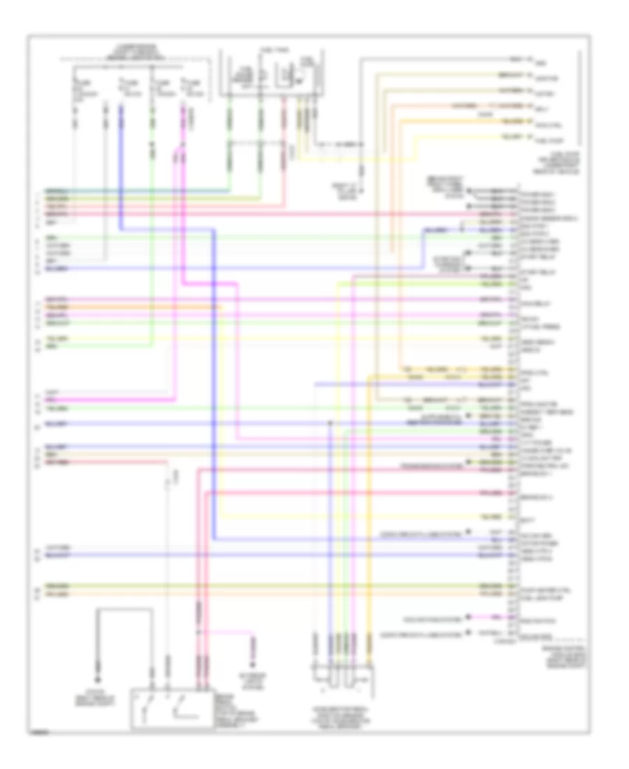
5.0L, Engine Performance Wiring Diagram (6 of 6) for Jaguar XF 2011
 https://portal-diagnostov.com/license.html
Automotive Electricians Portal FZCO
Automotive Electricians Portal FZCO
https://portal-diagnostov.com/license.html
https://portal-diagnostov.com/license.html
Automotive Electricians Portal FZCO
Automotive Electricians Portal FZCOList of elements for 5.0L, Engine Performance Wiring Diagram (6 of 6) for Jaguar XF 2011:
- (behind right front wheel arch liner) g1d108
- (right "c" pillar) g3d162
- (under engine compt fuse box) engine junction box
- 5v ref 1
- Accelerator pedal position sensor (top of accelerator pedal bracket)
- Ambient temp sens
- Ap-
- Ap1
- Ap2
- Ap2-
- Ap5v
- B bank sensor gnd 2
- Batt
- Brake pedal switch (top of brake pedal bracket assembly)
- Brake sw 1
- Brake sw 2
- C13-a
- C13-d
- C1bb01b
- C1e120a
- C44-e
- Computer data lines system
- Cooling fans system
- Ecm pwr 1
- Ecm pwr 2
- Engine control module (ecm) (right rear of engine compt)
- Exterior lights system
- Fpdm ctrl
- Fpdm monitor
- Fuel gauge sender unit
- Fuel leak pump
- Fuel pump
- Fuel pump driver module (under right rear of vehicle)
- Fuel tank
- Fuse 10a/30a
- Fuse 10a/30a/ 5a
- Fuse 5a/10a
- Fuse 5a/15a
- G1d120 (right rear of engine compt)
- Gnd
- Hange over valve
- Hego b
- Hego htr a
- Hego htr b
- Hego sens a
- Hs can pos
- Ic coolant pmp
- Ign sw
- Lp fuel press
- Main relay
- Monitor
- Motor -
- Motor power
- Nca
- Ox sens a gnd
- Ox sens b gnd
- Park/neutral sw
- Power gnd 1
- Power gnd 2
- Power gnd 3
- Pump heater ctrl
- Pwm ctrl
- Rad fan pwm
- Sply
- Srs sig
- Start relay
- Starting/ charging system
- Transmissions system
- Vvt power
5.0L SC
5.0L SC, Engine Performance Wiring Diagram (1 of 6) for Jaguar XF 2011
 https://portal-diagnostov.com/license.html
Automotive Electricians Portal FZCO
Automotive Electricians Portal FZCO
https://portal-diagnostov.com/license.html
https://portal-diagnostov.com/license.html
Automotive Electricians Portal FZCO
Automotive Electricians Portal FZCOList of elements for 5.0L SC, Engine Performance Wiring Diagram (1 of 6) for Jaguar XF 2011:
- (on left cylinder bank fuel rail) fuel injector 5
- (on left cylinder bank fuel rail) fuel injector 6
- (on left cylinder bank fuel rail) fuel injector 7
- (on left cylinder bank fuel rail) fuel injector 8
- (on right cylinder bank fuel rail) fuel injector 1
- (on right cylinder bank fuel rail) fuel injector 2
- (on right cylinder bank fuel rail) fuel injector 3
- (on right cylinder bank fuel rail) fuel injector 4
- Air temp gnd
- C11-a
- C11-p
- C1e117
- Cam ex a
- Cam ex b
- Cam in a
- Cam in b
- Cam sen a gnd
- Cam sen b gnd
- Cam sen b sply
- Cam sens a
- Capacitor
- Coolant temp 2
- Crank sens
- Crank sens gnd
- Engine control module (ecm) (right rear of engine compt)
- Front knock sensor bank 2
- Fuel press sens
- Fuel pump 1
- Fuel pump 2
- Gref
- Htr ctrl
- Htr ctrl b
- Ignition coil 1 (top of right cylinder bank)
- Ignition coil 3 (top of right cylinder bank)
- Ignition coil 5 (top of left cylinder bank)
- Ignition coil 7 (top of left cylinder bank)
- Ignitor 1b
- Ignitor 2a
- Ignitor 2b
- Ignitor 3a
- Ignitor 3b
- Ignitor 4a
- Ignitor 4b
- Inj 1a commom
- Inj 1b commom
- Inj 2a
- Inj 2a commom
- Inj 2b
- Inj 2b common
- Inj 3a
- Inj 3b common
- Inj 4a
- Inj 4a common
- Inj 4b
- Inj 4b common
- Inlet air temp b
- Knock sens 1a
- Knock sens 1b
- Knock sens 2a
- Knock sens 2b
- Maf sens gnd a
- Map sens gnd
- P1080
- Rear knock sensor bank 2
- Sen gnd
- Sens gnd
- Sensor gnd
- Tmap sens
- Tps 5v feed
- Uhego a
- Uhego b
- Vref
5.0L SC, Engine Performance Wiring Diagram (2 of 6) for Jaguar XF 2011
 https://portal-diagnostov.com/license.html
Automotive Electricians Portal FZCO
Automotive Electricians Portal FZCO
https://portal-diagnostov.com/license.html
https://portal-diagnostov.com/license.html
Automotive Electricians Portal FZCO
Automotive Electricians Portal FZCOList of elements for 5.0L SC, Engine Performance Wiring Diagram (2 of 6) for Jaguar XF 2011:
- (5.0l sc) water pump relay (half iso)
- (behind right side of radiator) supercharger coolant pump
- (under engine compt fuse box) engine junction box
- C11-a
- C11-r
- C1bb01b
- Crankshaft position sensor (underside of engine, near transmission bellhousing)
- Engine coolant temperature sensor 1
- Engine coolant temperature sensor 2
- Front knock sensor bank 1
- Fuse 15a
- G1d131 (behind right headlight assembly)
- Gnd
- High pressure fuel pump 1
- High pressure fuel pump 2
- Ignition coil 2 (top of right cylinder bank)
- Ignition coil 4 (top of right cylinder bank)
- Ignition coil 6 (top of left cylinder bank)
- Ignition coil 8 (top of left cylinder bank)
- Inlet camshaft position sensor (bank 1)
- Inlet camshaft position sensor (bank 2)
- Nca
- Outlet camshaft position sensor (bank 1)
- Outlet camshaft position sensor (bank 2)
- P1080
- Pwr 5v
- Rear knock sensor bank 2
- Red
- Sens
5.0L SC, Engine Performance Wiring Diagram (3 of 6) for Jaguar XF 2011
 https://portal-diagnostov.com/license.html
Automotive Electricians Portal FZCO
Automotive Electricians Portal FZCO
https://portal-diagnostov.com/license.html
https://portal-diagnostov.com/license.html
Automotive Electricians Portal FZCO
Automotive Electricians Portal FZCOList of elements for 5.0L SC, Engine Performance Wiring Diagram (3 of 6) for Jaguar XF 2011:
- (info not available)
- (top center rear of engine) (5.0l sc) manifold absolute pressure sensor
- (top center rear of engine) manifold absolute pressure sensor
- (top right side of engine) fuel rail pressure sensor
- (upstream of left catalytic converter) even pre-catalyst oxygen sensor
- (upstream of right catalytic converter) odd pre-catalyst oxygen sensor
- +5v
- Active ext valve
- Ambient air temperature sensor
- C13-e
- C1e117
- C3a-a
- Coolant temp
- Cps a
- Cps b
- E box fan
- Engine control module (ecm) (right rear of engine compt)
- Fuel pump 1
- Fuel pump 2
- Gnd
- Ignitor 1a
- Imtv
- Inj 1b
- Inj 3b
- Injector 1a
- Inlet air temp a
- Lin
- Low fuel pressure sensor
- Maf sensor a
- Maf sensor b
- Map sensor
- Oil quality sens
- Purge valve
- Red
- Sig
- Starting/ charging system
- Temp
- Temp sens
- Throttle +
- Throttle -
- Throttle motor (on throttle body)
- Tps gnd
- Tps1
- Tps2
- Vfs ex b
- Vfs in a
- Vfs in b
- Vfsex a
- Vout
- Vref
5.0L SC, Engine Performance Wiring Diagram (4 of 6) for Jaguar XF 2011
 https://portal-diagnostov.com/license.html
Automotive Electricians Portal FZCO
Automotive Electricians Portal FZCO
https://portal-diagnostov.com/license.html
https://portal-diagnostov.com/license.html
Automotive Electricians Portal FZCO
Automotive Electricians Portal FZCOList of elements for 5.0L SC, Engine Performance Wiring Diagram (4 of 6) for Jaguar XF 2011:
- (left rear of engine compt) g1d123
- (lower right front of engine) oil temperature level sensor
- C11-a
- C11-p
- C1bb01b
- Camshaft profile switching solenoid (bank 1) (5.0l)
- Camshaft profile switching solenoid (bank 2) (5.0l)
- Cooling fan control unit (behind right side of front bumper)
- Engine junction box (under engine compt fuse box)
- Exhaust vvt solenoid (bank 1)
- Exhaust vvt solenoid (bank 2)
- Fuse 10a
- Fuse 15a
- Fuse 20a/ 15a
- Fuse 50a
- Gnd
- Gnf
- High current ems relay
- Hot at all times
- Iat gnd
- Iat output
- Ignition relay (half iso)
- Intake vvt solenoid (bank 1)
- Intake vvt solenoid (bank 2)
- Maf sens
- Maf/iat sensor (bank 1)
- Maf/iat sensor (bank 2)
- Manifold intake tuning solenoid
- Purge control valve (top left side of engine)
- Pwr
- Red
- Sig
- Vref
5.0L SC, Engine Performance Wiring Diagram (5 of 6) for Jaguar XF 2011
 https://portal-diagnostov.com/license.html
Automotive Electricians Portal FZCO
Automotive Electricians Portal FZCO
https://portal-diagnostov.com/license.html
https://portal-diagnostov.com/license.html
Automotive Electricians Portal FZCO
Automotive Electricians Portal FZCOList of elements for 5.0L SC, Engine Performance Wiring Diagram (5 of 6) for Jaguar XF 2011:
- (right side of luggage compt) g4d173
- (under engine compt fuse box) engine junction box
- Battery junction box (right side of luggage compt)
- C11-p
- C13-a
- C13-d
- C1bb01b
- C3bp01f
- C3bp01h
- C3bp01j
- C4bf10b
- C4bp01a
- C4bp01d
- C4bp01l
- Central junction box (right kick panel)
- Computer data lines system
- Even post-catalyst oxygen sensor (downstream of left catalytic converter)
- Fuel pump relay
- Fuel sens a
- Fuel sens b
- Fuel sens rtn
- Fuse 20a
- Fuse 250a
- Fuse 25a
- Fuse 5a
- G1d123 (left rear of engine compt)
- Hego relay (full iso)
- Hot at all times
- Ign sply
- Leak detection unit (under left rear of vehicle)
- Ms can pos
- Odd post-catalyst oxygen sensor (downstream of right catalytic converter)
- Rear junction box (right side of luggage compt)
- Red
- Rsjb pwr gnd
- Uhego rly ctrl
5.0L SC, Engine Performance Wiring Diagram (6 of 6) for Jaguar XF 2011
 https://portal-diagnostov.com/license.html
Automotive Electricians Portal FZCO
Automotive Electricians Portal FZCO
https://portal-diagnostov.com/license.html
https://portal-diagnostov.com/license.html
Automotive Electricians Portal FZCO
Automotive Electricians Portal FZCOList of elements for 5.0L SC, Engine Performance Wiring Diagram (6 of 6) for Jaguar XF 2011:
- (behind right front wheel arch liner) g1d108
- (right "c" pillar) g3d162
- (under engine compt fuse box) engine junction box
- 5v ref 1
- Accelerator pedal position sensor (top of accelerator pedal bracket)
- Ambient temp sens
- Ap-
- Ap1
- Ap2
- Ap2-
- Ap5v
- B bank sensor gnd 2
- Batt
- Brake pedal switch (top of brake pedal bracket assembly)
- Brake sw 1
- Brake sw 2
- C13-a
- C13-d
- C1bb01b
- C1e120a
- C44-e
- Computer data lines system
- Cooling fans system
- Ecm pwr 1
- Ecm pwr 2
- Engine control module (ecm) (right rear of engine compt)
- Exterior lights system
- Fpdm ctrl
- Fpdm monitor
- Fuel gauge sender unit
- Fuel leak pump
- Fuel pump
- Fuel pump driver module (under right rear of vehicle)
- Fuel tank
- Fuse 10a/30a
- Fuse 10a/30a/ 5a
- Fuse 5a/10a
- Fuse 5a/15a
- G1d120 (right rear of engine compt)
- Gnd
- Hange over valve
- Hego b
- Hego htr a
- Hego htr b
- Hego sens a
- Hs can pos
- Ic coolant pmp
- Ign sw
- Lp fuel press
- Main relay
- Monitor
- Motor -
- Motor power
- Nca
- Ox sens a gnd
- Ox sens b gnd
- Park/neutral sw
- Power gnd 1
- Power gnd 2
- Power gnd 3
- Pump heater ctrl
- Pwm ctrl
- Rad fan pwm
- Sply
- Srs sig
- Start relay
- Starting/ charging system
- Transmissions system
- Vvt power
EXTERIOR LIGHTS
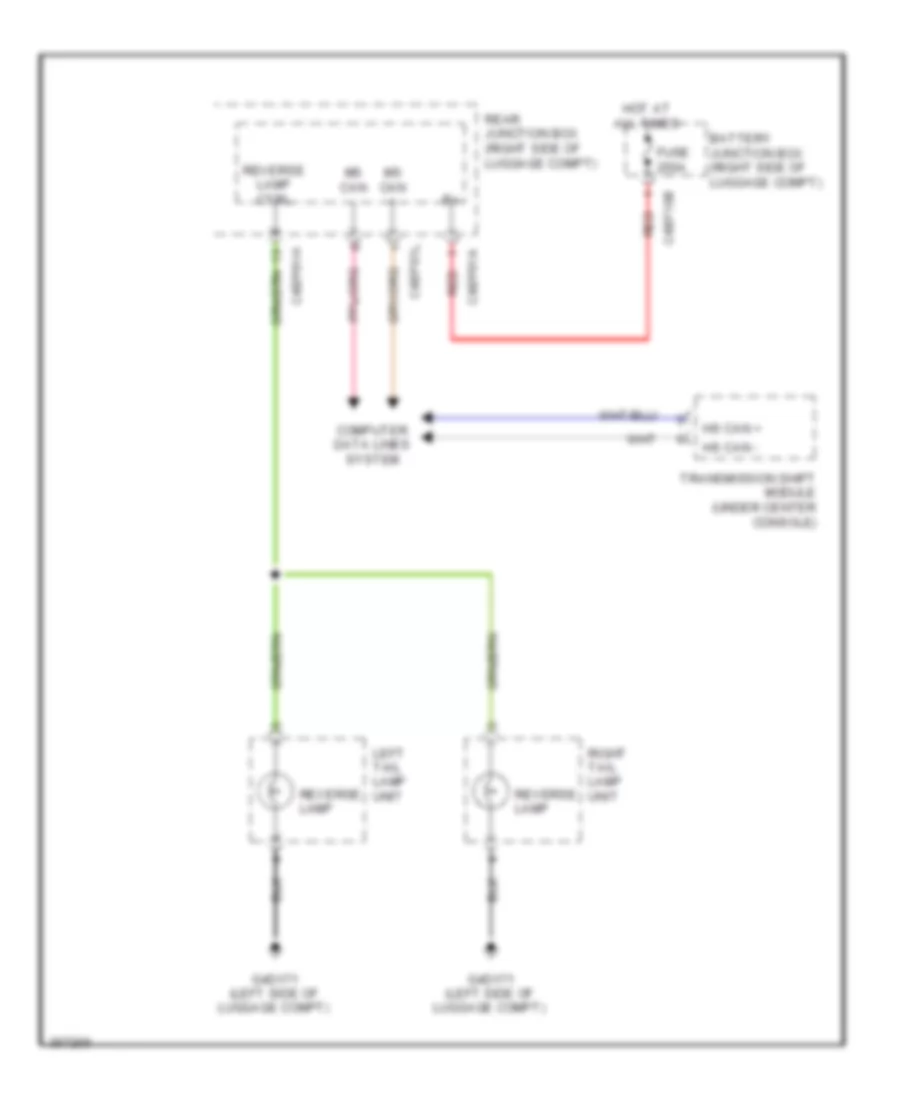
Backup Lamps Wiring Diagram for Jaguar XF 2011
 https://portal-diagnostov.com/license.html
Automotive Electricians Portal FZCO
Automotive Electricians Portal FZCO
https://portal-diagnostov.com/license.html
https://portal-diagnostov.com/license.html
Automotive Electricians Portal FZCO
Automotive Electricians Portal FZCOList of elements for Backup Lamps Wiring Diagram for Jaguar XF 2011:
- Battery junction box (right side of luggage compt)
- C4bf10b
- C4bp01a
- C4bp01h
- C4bp01l
- Computer data lines system
- Fuse 250a
- G4d171 (left side of luggage compt)
- Hot at all times
- Hs can +
- Hs can -
- Left tail lamp unit
- Ms can +
- Ms can -
- Rear junction box (right side of luggage compt)
- Red
- Reverse lamp
- Reverse lamp ctrl
- Right tail lamp unit
- Transmission shift module (under center console)
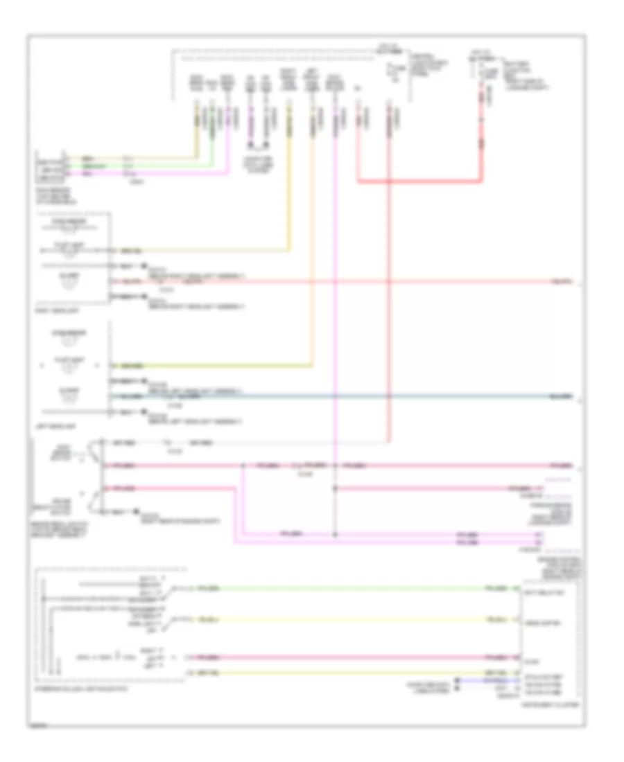
Exterior Lamps Wiring Diagram (1 of 2) for Jaguar XF 2011
 https://portal-diagnostov.com/license.html
Automotive Electricians Portal FZCO
Automotive Electricians Portal FZCO
https://portal-diagnostov.com/license.html
https://portal-diagnostov.com/license.html
Automotive Electricians Portal FZCO
Automotive Electricians Portal FZCOList of elements for Exterior Lamps Wiring Diagram (1 of 2) for Jaguar XF 2011:
- Autolamp
- Battery junction box (right side of luggage compt)
- Brake pedal switch (top of brake pedal bracket assembly)
- C13-a
- C13-b
- C13-d
- C13-e
- C1e120a
- C2mc01a
- C3bp01a
- C3bp01e
- C3bp01f
- C3bp01h
- C3bp01k
- C3bp01l
- C49-a
- C4bf10c
- C4cb01b
- Central junction box (right kick panel)
- Computer data lines system
- Cruise deactivation switch
- Di lamp
- Di sw
- Dip beam
- Engine control module (ecm) (right rear of engine compt)
- Exit 1
- Exit 2
- Exit 3
- Exit delay sw
- Foot brake sw sig
- Foot brake switch
- Fuse 250a
- Fuse 5a
- G1d120 (right rear of engine compt)
- G1d129 (behind left headlight assembly)
- G1d131 (behind right headlight assembly)
- Headlamp sw
- Hot at all times
- Hs can in pos
- Instrument cluster
- Left
- Left front
- Left headlamp
- Ms can pos
- Off
- Parking brake module (right rear of luggage compt)
- Pilot lamp
- Rain lin
- Rain sens gnd
- Rain sens pwr
- Rain sensor (top center of windshield)
- Red
- Right
- Right front side lamps
- Right headlamp
- Sen pwr
- Sen rtn
- Sen sig
- Side lamps
- Side light
- Side marker
- Stalk sw ret
- Steering column lighting switch
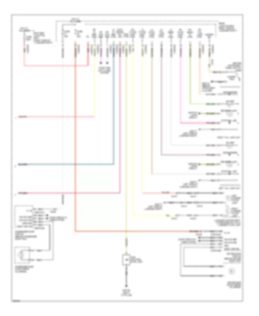
Exterior Lamps Wiring Diagram (2 of 2) for Jaguar XF 2011
 https://portal-diagnostov.com/license.html
Automotive Electricians Portal FZCO
Automotive Electricians Portal FZCO
https://portal-diagnostov.com/license.html
https://portal-diagnostov.com/license.html
Automotive Electricians Portal FZCO
Automotive Electricians Portal FZCOList of elements for Exterior Lamps Wiring Diagram (2 of 2) for Jaguar XF 2011:
- Backup lamps circuit
- Battery junction box (right side of luggage compt)
- C23-r
- C38-b
- C3a-b
- C44-a
- C44-c
- C4bf01b
- C4bp011a
- C4bp01d
- C4bp01g
- C4bp01h
- C4bp01k
- C4bp01l
- Capwo2a
- Capwo2b
- Cbpw04a
- Cbpw04b
- Center instrument panel switch pack
- Computer data lines system
- Di lamp
- Driver door module (behind driver door trim)
- Driver side door mirror (in mirror)
- Foot brake sw sig
- Fuse 250a
- Fuse 25a
- G2d116 (behind instrument cluster)
- G3d162 (right "c" pillar)
- G4d171 (left side of luggage compt)
- Gnd
- Hazard sw
- High mounted stop lamp
- Hmsl ctrl
- Hot at all times
- Kl 30
- Left license plate lamp
- Left tail lamp unit
- Lf di rep ctrl
- Lh plate lamp ctrl
- Lh rear di ctrl
- Lh stop lamp ctrl
- Lh tail lamp ctrl
- Luggage compartment lid release switch & license plate lamp
- Mirr gnd
- Ms can pos
- Passenger door module (behind passenger door trim)
- Passenger side door mirror (in mirror)
- Rear junction box (right side of luggage compt)
- Red
- Reverse lamp
- Rf di rep ctrl
- Rh plate lamp ctrl
- Rh rear di ctrl
- Rh stop lamp ctrl
- Rh tail lamp ctrl
- Right license plate lamp
- Right tail lamp unit
- Side marker
- Side turn ind
- Stop/tail led
GROUND DISTRIBUTION
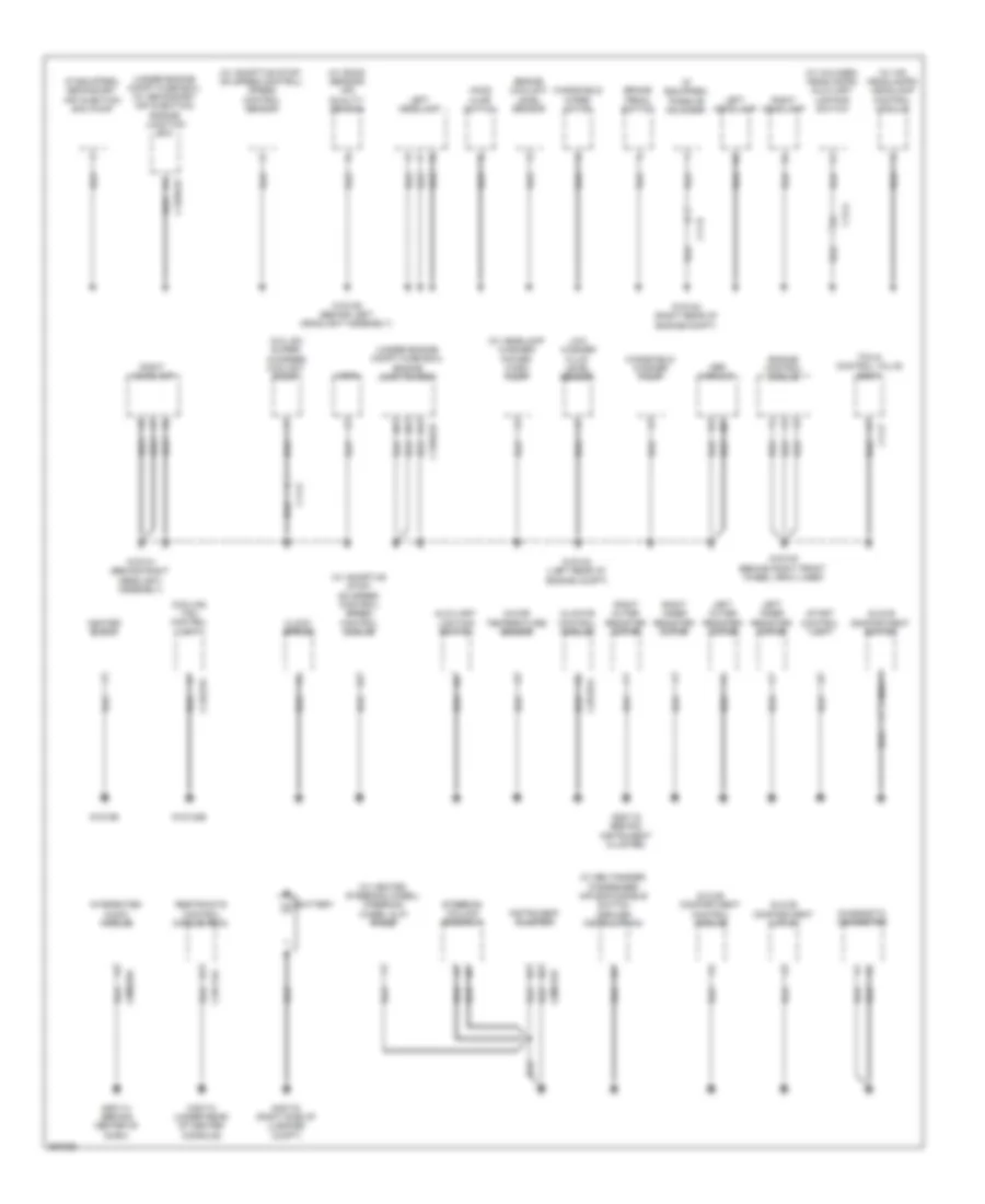
Ground Distribution Wiring Diagram (1 of 3) for Jaguar XF 2011
 https://portal-diagnostov.com/license.html
Automotive Electricians Portal FZCO
Automotive Electricians Portal FZCO
https://portal-diagnostov.com/license.html
https://portal-diagnostov.com/license.html
Automotive Electricians Portal FZCO
Automotive Electricians Portal FZCOList of elements for Ground Distribution Wiring Diagram (1 of 3) for Jaguar XF 2011:
- (5.0l sc) super- charger coolant pump
- (if equipped) passive sounder
- (if equipped) secondary air injection (sai) pump
- (under engine compt fuse box) (w/ secondary air injection) engine junction box
- (under engine compt fuse box) engine junction box
- (w/ adaptive stop/ go speed control) speed control module
- (w/ adaptive stop/ go speed control) speed control sensor
- (w/ beltminder) passenger air bag disable switch (dealer installation)
- (w/ halogen headlamps) auxiliary lighting switch
- (w/ headlamp washer) power wash pump
- (w/ heated steering wheel) steering wheel slip rings
- (w/ hid headlamps) headlamp control module
- (w/ smog sensor) air quality sensor
- Abs module
- Auxiliary lighting switch
- Battery
- Brake pedal switch
- C11-b
- C11-p
- C11-r
- C12-a
- C1bb01b
- C1ec01d
- C2h101a
- C2mc01b
- C2me03a
- C3d174 (under rear of center console)
- C3r114a
- Climate control module
- Clock spring
- Cooling fan control unit
- Diagnostic connector
- Engine control module
- Engine coolant level sensor
- G1d108 (behind right front wheel arch liner)
- G1d120 (right rear of engine compt)
- G1d123 (left rear of engine compt)
- G1d129 (behind left headlight assembly)
- G1d131 (behind right headlight assembly)
- G1d132b
- G1d169
- G2d114 (behind center of dash)
- G2d115 (behind instrument cluster)
- G4d178 (right side of luggage compt)
- Glove compartment control module
- Glove compartment latch
- Glove compartment switch
- Heater block
- Hood ajar switch
- Horn
- In-car temperature sensor
- Instrument cluster
- Integrated audio module
- Left headlamp
- Left inner register motor
- Left outer register motor
- Low washer fluid level sensor
- Nca
- Restraints control module (rcm)
- Right headlamp
- Right inner register motor
- Right outer register motor
- Start control unit
- Steering column assembly
- Tcm & control valve body
- Windshield washer pump
- Windshield wiper motor
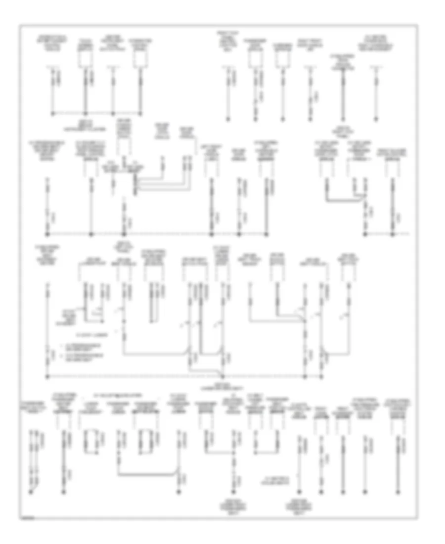
Ground Distribution Wiring Diagram (2 of 3) for Jaguar XF 2011
 https://portal-diagnostov.com/license.html
Automotive Electricians Portal FZCO
Automotive Electricians Portal FZCO
https://portal-diagnostov.com/license.html
https://portal-diagnostov.com/license.html
Automotive Electricians Portal FZCO
Automotive Electricians Portal FZCOList of elements for Ground Distribution Wiring Diagram (2 of 3) for Jaguar XF 2011:
- (if equipped)
- (if equipped) continuously variable damping module
- (if equipped) driver seat backrest heater
- (if equipped) driver seat bolster solenoid
- (if equipped) left windshield heater element
- (if equipped) occupancy seat module
- (if equipped) road pricing connector
- (right kick panel) central junction box
- (w/ 2way lumbar) driver lumbar pump
- (w/ 2way lumbar) passenger pump lumbar
- (w/ adjustable bolster)
- (w/ belt minder) mat pressure sensor
- (w/ heated windshield) right windshield heater element
- (w/ keyless entry) passenger door handle
- (w/ keyless entry) passenger door latch module
- (w/ power tilt/ slide sunroof) roof opening panel control module
- (w/ programmable drivers seat) driver seat memory switch
- 16 way driver seat movement
- C23-l
- C2mc02a
- C2mt01a
- C33-c
- C33-d
- C33-e
- C33-g
- C33-h
- C3a-a
- C3a-b
- C3b-a
- C3b-b
- C3bp01d
- C3cd01b
- C3hs03a
- C3hs06a
- C3ps02d
- C3ps12a
- C3ps12b
- C3ps13a
- C3ps13b
- C3ps21
- C3ps22d
- C3ps22e
- C3ps32c
- C3ps91
- C3ps93
- C3r118
- C3r122
- C9rd03b
- Capw02a
- Cbpw04a
- Center instrument panel switch pack
- Climate controlled seat module
- Driver buckle switch
- Driver door handle
- Driver door latch module
- Driver door module
- Driver lumbar pump
- Driver seat module
- Driver seat pack switch
- Driver seat switch pack
- Driver seat track sensor
- Driver window mirror switch pack
- Drivers seat
- Front accessory socket
- Front blower motor control module
- Front cigar lighter
- G2d116 (behind instrument cluster)
- G3d133 (left kick panel)
- G3d138 (right kick panel)
- G3d182a (under driver's seat)
- G3d183a (under front passenger's seat)
- G3d183b (under front passenger's seat)
- Information & entertainment control module
- Integrated control panel
- Left front door handle led
- Lumbar pump solenoid
- Overhead console
- Passenger buckle switch
- Passenger door module
- Passenger heater seat backrest
- Passenger pump lumbar
- Passenger seat position sensor
- Passenger seat switch pack
- Passenger solenoid seat bolster
- Right front door handle led
- Tire pressure monitoring system module
- Touch screen display
- W/ 2way lumbar
- W/ heated & cooled seats
- W/ keyless entry
- W/ programmable drivers seat
- W/o keyless entry
- W/o programmable
Ground Distribution Wiring Diagram (3 of 3) for Jaguar XF 2011
 https://portal-diagnostov.com/license.html
Automotive Electricians Portal FZCO
Automotive Electricians Portal FZCO
https://portal-diagnostov.com/license.html
https://portal-diagnostov.com/license.html
Automotive Electricians Portal FZCO
Automotive Electricians Portal FZCOList of elements for Ground Distribution Wiring Diagram (3 of 3) for Jaguar XF 2011:
- (if equipped)
- (if equipped) iboc radio module
- (if equipped) left blind spot monitoring module
- (if equipped) navigation system module
- (if equipped) right blind spot monitoring module
- (if equipped) sun blind motor
- (if equipped) television receiver
- (if equipped) tire pressure monitoring receiver
- (right side of luggage compt) rear junction box
- (w/ electrochromic interior mirror) interior mirror
- (w/ park aid camera) rear view camera
- (w/ usb) portable audio interface module
- Audio amplifier
- C33-a
- C33-c
- C37-a
- C38-a
- C3me17a
- C3mm01a
- C44-a
- C44-c
- C44-e
- C44-v
- C49-a
- C4bp01d
- C4bp01k
- C4cb01b
- C4me22a
- C4me33a
- C4mn23a
- C4mp01a
- C4pk28c
- Driver pump fuel module
- Fuel flap release motor
- Fuel tank
- G3d161 (left "c" pillar)
- G3d162 (right "c" pillar)
- G3d182b (under driver's seat)
- G4d171 (left side of luggage compt)
- G4d172 (left side of luggage compt)
- G4d173 (right side of luggage compt)
- High mounted stop lamp
- Keyless vehicle module
- Left rear door latch module
- Left rear door module
- Left rear fog lamp
- Left sun visor lamp
- Left tail lamp unit
- Liftgate latch/ luggage compartment lid latch
- Luggage compartment lamp
- Luggage compartment lid release switch & license plate lamp
- Nca
- Parking aid module
- Parking brake module
- Radio frequency receiver (rf)
- Rear interior lamp
- Right blind spot monitoring module
- Right rear door handle module
- Right rear door latch module
- Right rear door module
- Right rear fog lamp
- Right sun visor lamp
- Right tail lamp unit
- Sdars module
- Transit relay
- Transmission shift module
- W/ keyless entry
- Yaw rate sensor
HEADLIGHTS
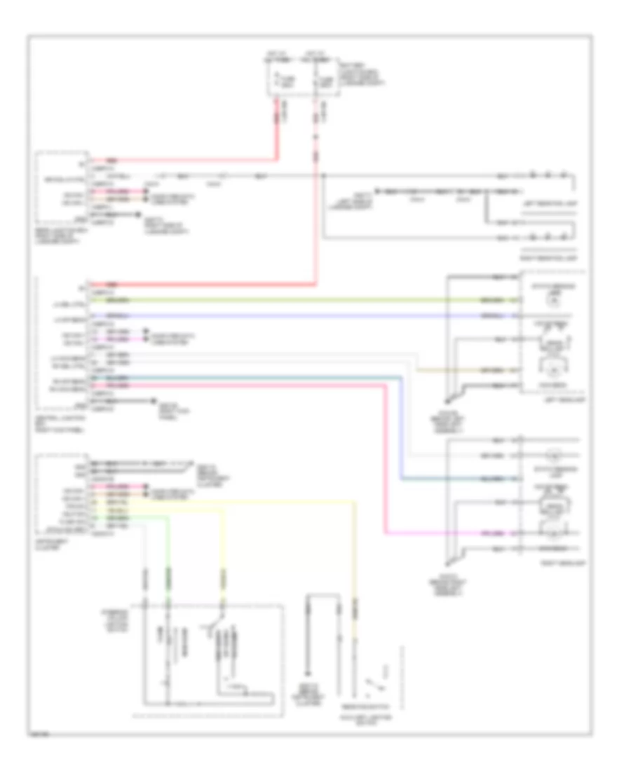
Headlamps & Front Fog Lamps Wiring Diagram, with High Intensity Discharge for Jaguar XF 2011
 https://portal-diagnostov.com/license.html
Automotive Electricians Portal FZCO
Automotive Electricians Portal FZCO
https://portal-diagnostov.com/license.html
https://portal-diagnostov.com/license.html
Automotive Electricians Portal FZCO
Automotive Electricians Portal FZCOList of elements for Headlamps & Front Fog Lamps Wiring Diagram, with High Intensity Discharge for Jaguar XF 2011:
- Autolamp
- Auxiliary lighting switch
- Battery junction box (right side of luggage compt)
- C2mc01a
- C2mc01b
- C3bp01a
- C3bp01d
- C3bp01g
- C3bp01h
- C3bp01k
- C44-a
- C44-c
- C4bf10b
- C4bf10c
- C4bp01a
- C4bp01d
- C4bp01h
- C4bp01l
- Central junction box (right kick panel)
- Computer data lines system
- Dip beam
- Flash
- Flash sw
- Fog sw
- Fuse 250a
- G1d129 (behind left headlight assembly)
- G1d131 (behind right headlight assembly)
- G2d115 (behind instrument cluster)
- G3d138 (right kick panel)
- G4d171 (left side of luggage compt)
- G4d173 (right side of luggage compt)
- Gnd
- Hdlp sw
- Hid dip beam
- Hot at all times
- Instrument cluster
- Left headlamp
- Left rear fog lamp
- Lh dip beam
- Lh main beam
- Lh sbl ctrl
- Main beam
- Ms can +
- Ms can -
- Off
- Rear fog switch
- Rear junction box (right side of luggage compt)
- Red
- Rh dip beam
- Rh main beam
- Rh sbl ctrl
- Right headlamp
- Right rear fog lamp
- Rr fog lp ctrl
- Side light
- Stalk sw ret
- Static bending lamp
- Steering column lighting switch
- Xenon ballast
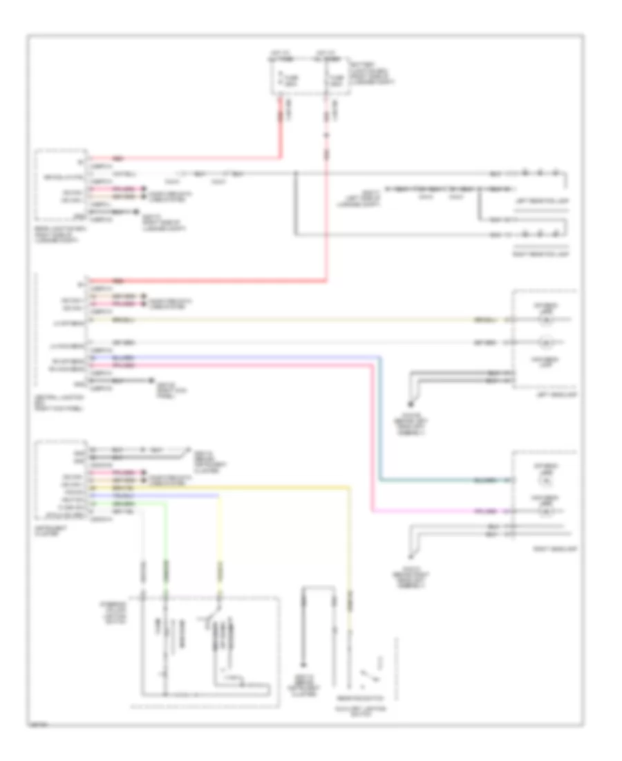
Headlamps & Front Fog Lamps Wiring Diagram, without High Intensity Discharge for Jaguar XF 2011
 https://portal-diagnostov.com/license.html
Automotive Electricians Portal FZCO
Automotive Electricians Portal FZCO
https://portal-diagnostov.com/license.html
https://portal-diagnostov.com/license.html
Automotive Electricians Portal FZCO
Automotive Electricians Portal FZCOList of elements for Headlamps & Front Fog Lamps Wiring Diagram, without High Intensity Discharge for Jaguar XF 2011:
- Autolamp
- Auxiliary lighting switch
- Battery junction box (right side of luggage compt)
- C2mc01a
- C2mc01b
- C3bp01a
- C3bp01d
- C3bp01g
- C3bp01h
- C3bp01k
- C44-a
- C44-c
- C4bf10b
- C4bf10c
- C4bp01a
- C4bp01d
- C4bp01h
- C4bp01l
- Central junction box (right kick panel)
- Computer data lines system
- Dip beam
- Dip beam lamp
- Flash
- Flash sw
- Fog sw
- Fuse 250a
- G1d129 (behind left headlight assembly)
- G1d131 (behind right headlight assembly)
- G2d115 (behind instrument cluster)
- G3d138 (right kick panel)
- G4d171 (left side of luggage compt)
- G4d173 (right side of luggage compt)
- Gnd
- Hdlp sw
- Hot at all times
- Instrument cluster
- Left headlamp
- Left rear fog lamp
- Lh dip beam
- Lh main beam
- Main beam
- Main beam lamp
- Ms can +
- Ms can -
- Off
- Rear fog switch
- Rear junction box (right side of luggage compt)
- Red
- Rh dip beam
- Rh main beam
- Right headlamp
- Right rear fog lamp
- Rr fog lp ctrl
- Side light
- Stalk sw ret
- Steering column lighting switch
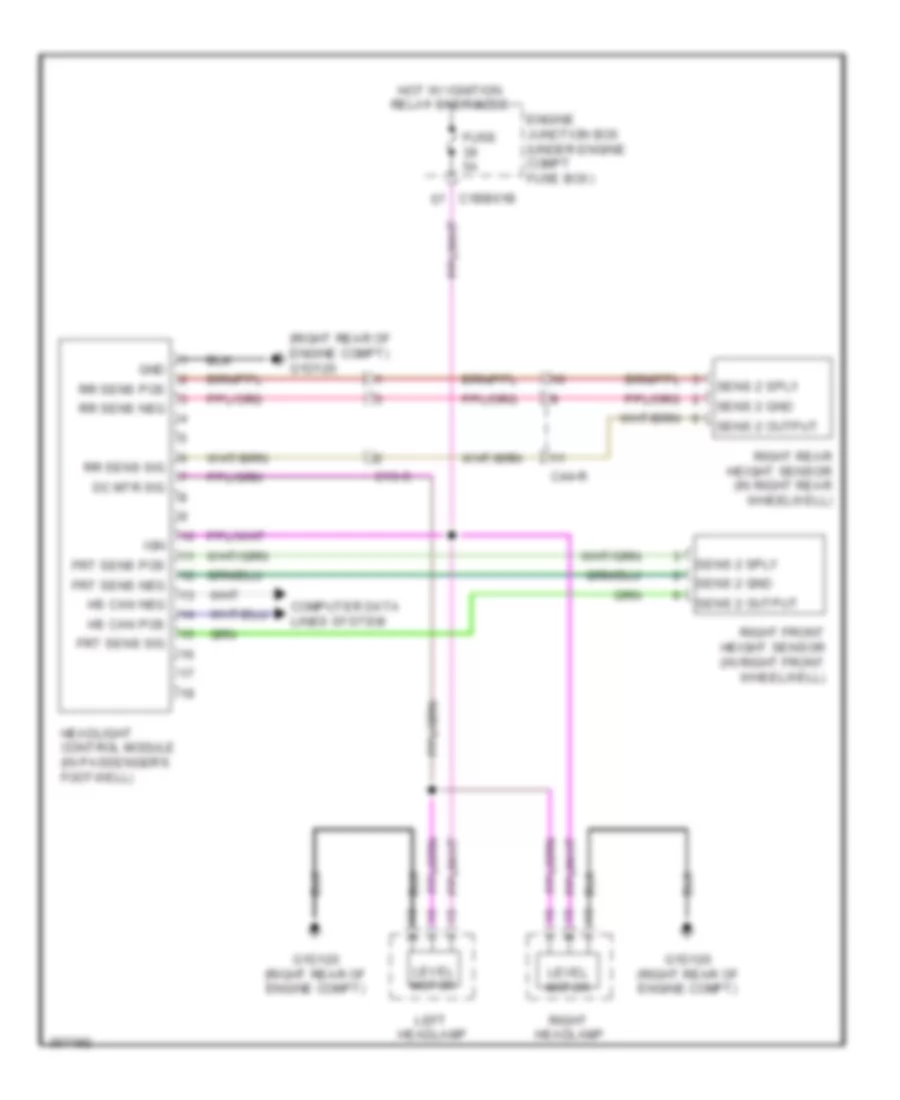
Headlamps Leveling Wiring Diagram for Jaguar XF 2011
 https://portal-diagnostov.com/license.html
Automotive Electricians Portal FZCO
Automotive Electricians Portal FZCO
https://portal-diagnostov.com/license.html
https://portal-diagnostov.com/license.html
Automotive Electricians Portal FZCO
Automotive Electricians Portal FZCOList of elements for Headlamps Leveling Wiring Diagram for Jaguar XF 2011:
- (right rear of engine compt) g1d120
- C13-c
- C1bb01b
- C44-r
- Computer data lines system
- Dc mtr sig
- Engine junction box (under engine compt fuse box)
- Frt sens pos
- Frt sens sig
- Fuse 5a
- G1d120 (right rear of engine compt)
- Gnd
- Headlight control module (in passenger's footwell)
- Hot w/ ignition relay energized
- Hs can pos
- Ign
- Left headlamp
- Level motor
- Right front height sensor (in right front wheelwell)
- Right headlamp
- Right rear height sensor (in right rear wheelwell)
- Rr sens pos
- Rr sens sig
- Sens 2 gnd
- Sens 2 output
- Sens 2 sply
HORN
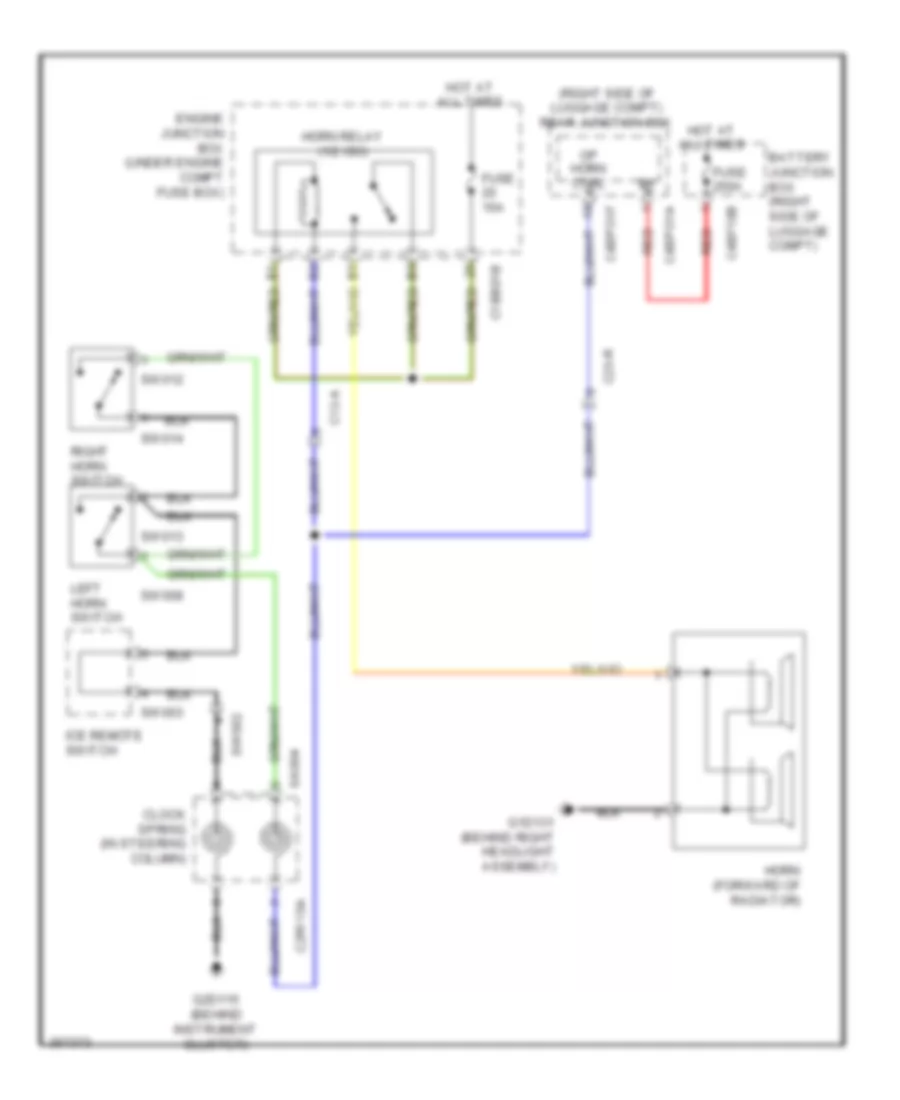
Horn Wiring Diagram for Jaguar XF 2011
 https://portal-diagnostov.com/license.html
Automotive Electricians Portal FZCO
Automotive Electricians Portal FZCO
https://portal-diagnostov.com/license.html
https://portal-diagnostov.com/license.html
Automotive Electricians Portal FZCO
Automotive Electricians Portal FZCOList of elements for Horn Wiring Diagram for Jaguar XF 2011:
- (right side of luggage compt) rear junction box
- Battery junction box (right side of luggage compt)
- C12-a
- C1bb01b
- C23-r
- C2r115a
- C4bf10b
- C4bpo1a
- C4bpo1f
- Clock spring (in steering column)
- Engine junction box (under engine compt fuse box)
- Fuse 15a
- Fuse 250a
- G1d131 (behind right headlight assembly)
- G2d115 (behind instrument cluster)
- Horn (forward of radiator)
- Horn relay (1/2 iso)
- Hot at all times
- Ice remote switch
- Left horn switch
- Op horn ctrl
- Red
- Right horn switch
- Sa004
- Sw002
- Sw003
- Sw008
- Sw012
- Sw013
- Sw014
INSTRUMENT CLUSTER
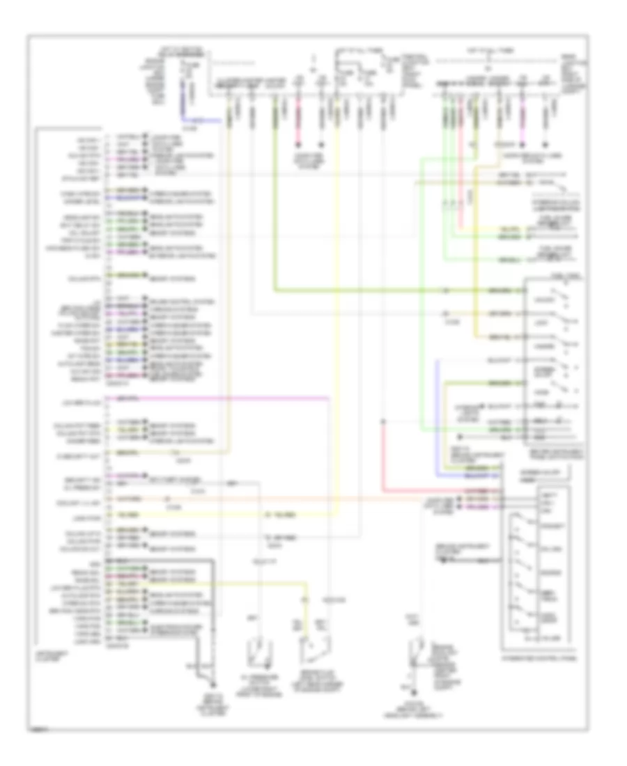
Instrument Cluster Wiring Diagram for Jaguar XF 2011
 https://portal-diagnostov.com/license.html
Automotive Electricians Portal FZCO
Automotive Electricians Portal FZCO
https://portal-diagnostov.com/license.html
https://portal-diagnostov.com/license.html
Automotive Electricians Portal FZCO
Automotive Electricians Portal FZCOList of elements for Instrument Cluster Wiring Diagram for Jaguar XF 2011:
- (behind instrument cluster) g2d116
- Anti-theft system
- Audio on/off
- Auto man
- Autolamp rtn
- Autolamp sens
- Aux sw rtn
- Aux sw sig
- Brake fluid level switch (left rear corner of engine compt)
- Brk pad wear rtn
- C11-p
- C12-a
- C12-b
- C1bb01b
- C23-d
- C23-r
- C2mc01a
- C2mc01b
- C3bp01d
- C3bp01f
- C3bp01g
- C3bp01j
- C3bp01k
- C44-e
- C4bp01f
- C4bp01k
- C4bp0l
- Can +
- Can -
- Cd eject
- Cd load
- Center instrument panel switch pack
- Central junction box (right kick panel)
- Cluster security
- Col adjust
- Column dn out
- Column pot feed
- Column pot rtn
- Column pwr
- Column rtn
- Column up in
- Computer data lines system
- Coolant lvl sw
- Cruise control system
- Di sw
- Dimmer feed
- Dimmer level
- Electronic power steering system
- Engine coolant level sensor (center front of engine compt)
- Engine junction box (under engine compt fuse box)
- Exit delay sw
- Exterior lights system
- Flick wiper sw
- Fog sw
- Fuel gauge sender unit
- Fuel guage sender unit
- Fuel tank
- Fuse 10a
- Fuse 5a
- G1d129 (behind left headlight assembly)
- G2d115 (behind instrument cluster)
- G2d116 (behind instrument cluster)
- Gnd
- Gref
- Hazard
- Hazard signal
- Hazard switch
- Headlamp sw
- Headlights system
- Headlights system trunk, tailgate & fuel doors system memory systems
- Home
- Hot at all times
- Hot w/ ignition relay energized
- Hs can +
- Hs can -
- Ic security out
- Illu
- Instrument cluster
- Int wipe sw
- Integrated control panel
- Interior lights system
- Lin brk pad wear column adjust
- Lock
- Logic gnd
- Logic pwr
- Low brk fluid
- Low brk fluid rtn
- Main beam flash sw
- Master lock
- Master unlock
- Master wiper sw
- Memory systems
- Ms can +
- Ms can -
- Oil press sw
- Oil pressure switch (lower right front of engine)
- Rake pot
- Rake sol
- Reach pot
- Reach sol
- Rear junction box (right side of luggage compt)
- Screen on off
- Security ind
- Seek/ track
- Source
- Sply
- Stalk sw ret
- Steering column lighting switch
- Trip cycle sw
- Unlock
- Vaps pos
- Vaps pwr
- Vbatt
- Volume
- Warning systems
- Wash wipe sw
- Wiper sw rtn
- Wiper/washer system
INTERIOR LIGHTS
Courtesy Lamps Wiring Diagram (1 of 2) for Jaguar XF 2011
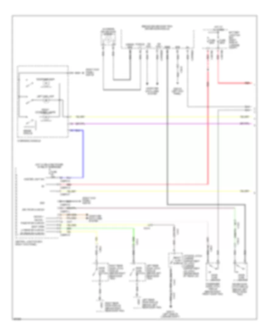 https://portal-diagnostov.com/license.html
Automotive Electricians Portal FZCO
Automotive Electricians Portal FZCO
https://portal-diagnostov.com/license.html
https://portal-diagnostov.com/license.html
Automotive Electricians Portal FZCO
Automotive Electricians Portal FZCOList of elements for Courtesy Lamps Wiring Diagram (1 of 2) for Jaguar XF 2011:
- (behind driver door trim) driver door module
- (in mirror) driver door mirror
- (right kick panel) g3d138
- Ajar switch
- Battery junction box (right side of luggage compt)
- Boot
- Boot open
- C13-a
- C37-a
- C38-a
- C3a-a
- C3a-b
- C3bp01a
- C3bp01d
- C3bp01f
- C3bp01j
- C3bp01k
- C44-a
- C44-c
- C4bf10b
- C4bf10c
- Capw02a
- Capw02b
- Central junction box (right kick panel)
- Computer data lines system
- Door ajar switch
- Driver door latch module (behind left front door trim)
- Drv fr dr ajar sw
- Front courtesy lamps
- Fuse 10a
- Fuse 250a
- G3d133 (left kick panel)
- G4d171 (left side of luggage compt)
- Gnd
- Gref
- Hot at all times
- Hot w/ delayed power of relay energized
- Left map lamp
- Left rear door latch module (behind left rear door trim)
- Left rear door module (behind left rear door trim)
- Lh rear dr ajar sw
- Liftgate latch/ luggage compartment lid latch (luggage compartment lid latch: center rear of trunk lid)
- Master light sw
- Mirror gnd
- Ms can +
- Ms can -
- Overhead console
- Pass fr dr ajar sw
- Passenger door latch module (behind right front door trim)
- Puddle lt
- Red
- Rh rear dr ajar sw
- Right map lamp
- Right rear door latch module (behind right rear door trim)
- Right rear door module (behind right rear door trim)
- Sense module
Courtesy Lamps Wiring Diagram (2 of 2) for Jaguar XF 2011
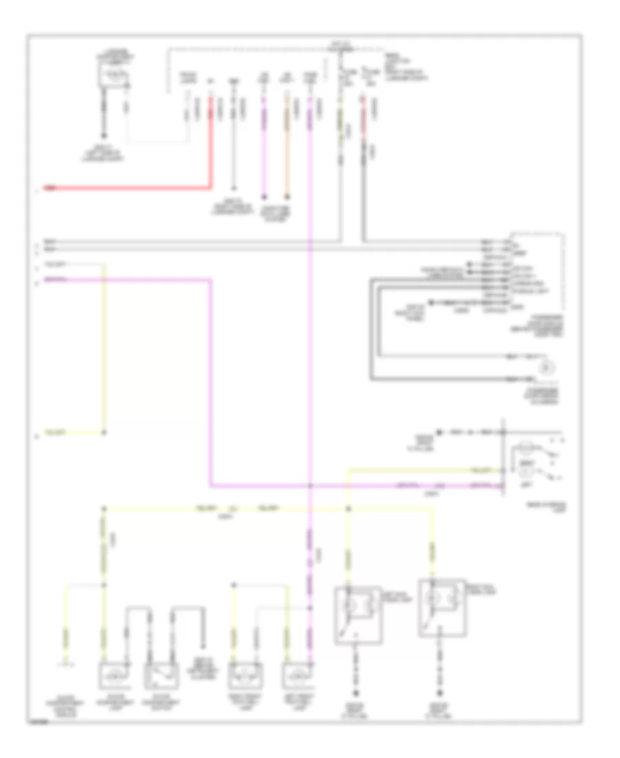 https://portal-diagnostov.com/license.html
Automotive Electricians Portal FZCO
Automotive Electricians Portal FZCO
https://portal-diagnostov.com/license.html
https://portal-diagnostov.com/license.html
Automotive Electricians Portal FZCO
Automotive Electricians Portal FZCOList of elements for Courtesy Lamps Wiring Diagram (2 of 2) for Jaguar XF 2011:
- C23-d
- C23-r
- C3a-b
- C3b-b
- C49-a
- C4bp01d
- C4bp01f
- C4bp01l
- C4bpo1a
- C4bpo1h
- Capw02a
- Cbpw04a
- Cbpw04b
- Computer data lines system
- Fade ctrl
- Fuse 25a
- G2d115 (behind instrument cluster)
- G3d138 (right kick panel)
- G3d162 (right "c" pillar)
- G4d171 (left side of luggage compt)
- G4d173 (right side of luggage compt)
- Glove compartment control module
- Glove compartment lamp
- Glove compartment switch
- Gnd
- Gref
- Hot at all times
- Left
- Left front footwell lamp
- Left sun visor lamp
- Luggage compartment lamp
- Mirror gnd
- Ms can +
- Ms can -
- Nca
- Passenger door mirror (in mirror)
- Passenger door module (behind passenger door trim)
- Puddle light
- Rear interior lamp
- Rear junction box (right side of luggage compt)
- Red
- Right
- Right front footwell lamp
- Right sun visor lamp
- Trunk lamps
Instrument Illumination Wiring Diagram for Jaguar XF 2011
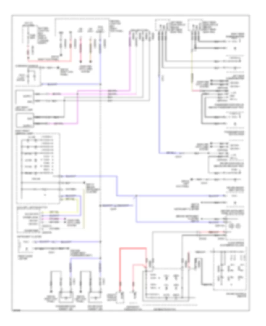 https://portal-diagnostov.com/license.html
Automotive Electricians Portal FZCO
Automotive Electricians Portal FZCO
https://portal-diagnostov.com/license.html
https://portal-diagnostov.com/license.html
Automotive Electricians Portal FZCO
Automotive Electricians Portal FZCOList of elements for Instrument Illumination Wiring Diagram for Jaguar XF 2011:
- (behind instrument cluster) g2d115
- (dealer fitted)
- Aux sw rtn
- Auxiliary lighting switch
- Battery junction box (right side of luggage compt)
- C23-r
- C2mc01a
- C2mc01b
- C2r115a
- C33-c
- C37-a
- C3a-a
- C3b-a
- C3bp01a
- C3bp01d
- C3bp01f
- C3bp01k
- C4bf10c
- Can
- Capw02a
- Capwo28
- Cbpw04a
- Cbpw04b
- Center instrument panel switch pack
- Central junction box (right kick panel)
- Clock spring (in steering column)
- Computer data lines system
- Cruise controls remote
- Dim ind
- Dimmer feed
- Dimmer level
- Downshift paddle switch
- Driver door ambient led
- Driver door module (behind driver door trim)
- Driver memory seat switch
- Fa ind
- Fog ind
- Front cigar lighter
- Fuse 250a
- G2d115 (behind instrument cluster)
- G2d116 (behind instrument cluster)
- G3d133 (left kick panel)
- G3d138 (right kick panel)
- G3d183b (under front passenger's seat)
- Gnd
- Halo illumi- nation
- Head+
- Head-
- Hl ind
- Hot at all times
- Ice remote switch
- Illum
- Instrument cluster
- Ip002a
- Ip002b
- Ip093a
- Ip093b
- L lin
- Ld ind
- Left front door sill lamp
- Left rear door module (behind left rear door trim)
- Left rear window switch
- Media
- Mem+
- Mem-
- Ms can +
- Ms can -
- Mute
- Nca
- Overhead console
- Passenger door ambient led
- Passenger door module (behind passenger door trim)
- Passenger door switch pack
- Red
- Res
- Right front door sill lamp
- Right rear door module (behind right rear door trim)
- Right rear window switch
- Sa004
- Set+
- Set-
- Sw ill
- Sw002
- Sw003
- Sw004
- Sw005
- Tr ind
- Upshift paddle switch
- Vol+
- Vol-
MEMORY SYSTEMS
Memory Mirrors Wiring Diagram for Jaguar XF 2011
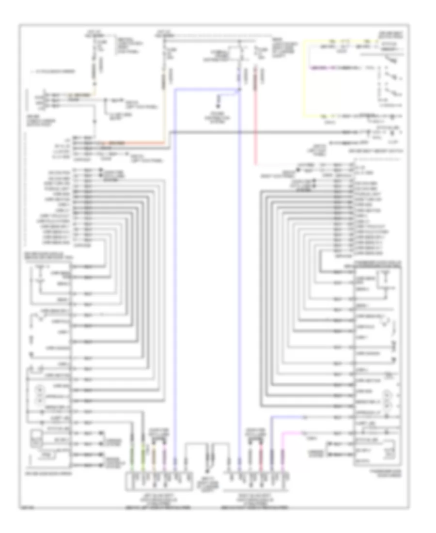 https://portal-diagnostov.com/license.html
Automotive Electricians Portal FZCO
Automotive Electricians Portal FZCO
https://portal-diagnostov.com/license.html
https://portal-diagnostov.com/license.html
Automotive Electricians Portal FZCO
Automotive Electricians Portal FZCOList of elements for Memory Mirrors Wiring Diagram for Jaguar XF 2011:
- Alert led
- Approach lp
- Auto dim
- B+ kl 30
- C33-d
- C3a-a
- C3a-b
- C3b-a
- C3b-b
- C3bp01g
- C4bp01d
- C4bp01h
- Capw02a
- Capw02b
- Cbpw04a
- Cbpw04b
- Central junction box (right kick panel)
- Computer data lines system
- Driver door module (behind driver door trim)
- Driver seat memory switch
- Driver seat switch pack
- Driver side door mirror
- Driver window mirror switch pack
- Ec rtn
- Ec sply
- Engine controls system
- Fuse 10a
- Fuse 25a
- G3d133 (left kick panel)
- G3d138 (right kick panel)
- G4d173 (right side of luggage compt)
- Gnd
- Hot at all times
- Ign
- Ign sply
- Illum
- Illum sw
- Internal power distribution
- Kl 30
- Kl 31 gnd
- Left blind spot monitoring module (if equipped) (behind left side of rear bumper)
- Lin
- Memory
- Mirr common
- Mirr fold
- Mirr fold in park
- Mirr gnd
- Mirr heating
- Mirr sens gnd
- Mirr sens in x
- Mirr sens in y
- Mirr sens sply
- Mirr x
- Mirr xy
- Mirr y
- Mirr y/fold out
- Mirrors system
- Ms can pos
- Passenger door module (behind passenger door trim)
- Passenger side door mirror
- Power distribution system
- Puddle light
- Pwr
- Rear junction box (right side of luggage compt)
- Repeater lp
- Right blind spot monitoring module (if equipped) (behind right side of rear bumper)
- Sens 1
- Sens 2
- Set
- Side turn ind
- Sply
- Status
- Status led
- W/ fold back mirror
- W/ keyless entry
Memory Seat Wiring Diagram (1 of 2) for Jaguar XF 2011
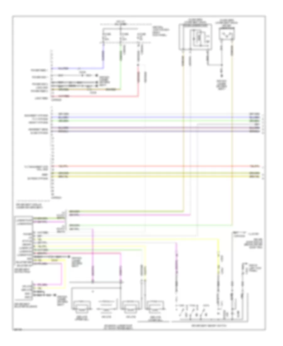 https://portal-diagnostov.com/license.html
Automotive Electricians Portal FZCO
Automotive Electricians Portal FZCO
https://portal-diagnostov.com/license.html
https://portal-diagnostov.com/license.html
Automotive Electricians Portal FZCO
Automotive Electricians Portal FZCOList of elements for Memory Seat Wiring Diagram (1 of 2) for Jaguar XF 2011:
- (in driver's lower seat back) driver lumbar pump
- Backrest mtr sns
- Bolster def
- Bolster inf
- C33-a
- C33-d
- C33-e
- C3bp01c
- C3bp01g
- C3ps02a
- C3ps02d
- Capw02a
- Central junction box (right kick panel)
- Deflate
- Deflate lower cell
- Deflate upper cell
- Driver door module (behind driver door trim)
- Driver seat bolster solenoid
- Driver seat memory switch
- Driver seat module (under driver's seat)
- Driver seat switch pack
- Extend mtr sns
- Fuse 20a
- Fuse 5a
- G3d133 (left kick panel)
- G3d182a (under driver's seat)
- Gnd
- Gnd 1
- Gnd 2
- Gref
- Headrest sens
- Height mtr sns
- Hot at all times
- Illum
- Illum sw
- Inflate
- Lin
- Logic feed
- Logic gnd
- Lumbar dn
- Lumbar fwd
- Lumbar pump
- Lumbar rwd
- Lumbar up
- Memory
- Power
- Power feed 1
- Power feed 2
- Power gnd 1
- Power gnd 2
- Set
- Slide mtr sns
- Solenoid lumbar pump (w/ 16-way power seat)
- Status
- Status led
- Tilt mtr sns
- Tilt/backrest mtr hall gnd
- W/ 10-way seats
- W/ 16-way seats
Memory Seat Wiring Diagram (2 of 2) for Jaguar XF 2011
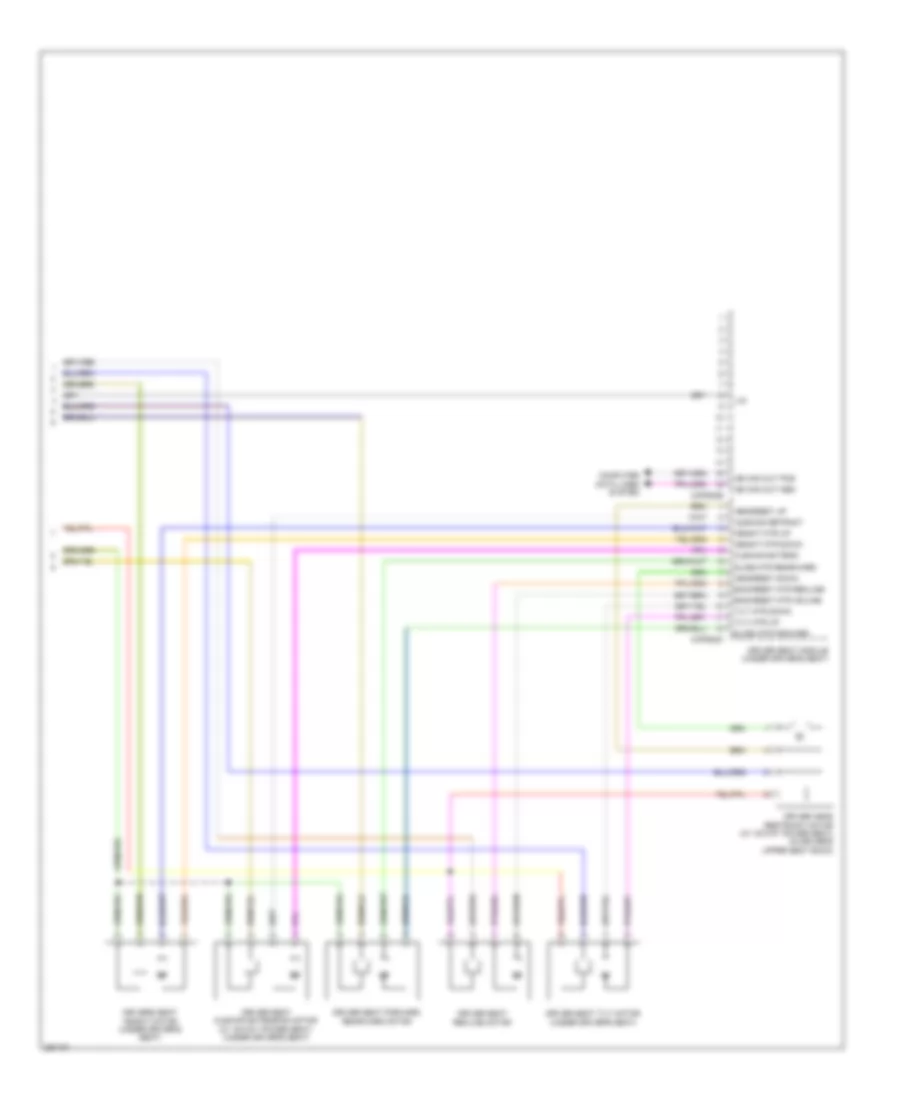 https://portal-diagnostov.com/license.html
Automotive Electricians Portal FZCO
Automotive Electricians Portal FZCO
https://portal-diagnostov.com/license.html
https://portal-diagnostov.com/license.html
Automotive Electricians Portal FZCO
Automotive Electricians Portal FZCOList of elements for Memory Seat Wiring Diagram (2 of 2) for Jaguar XF 2011:
- Backrest mtr incline
- Backrest mtr recline
- C3ps02b
- C3ps02c
- Computer data lines system
- Cushion extend
- Cushion retract
- Driver head restraint motor (w/ 16-way power seat) (in driver's upper seat back)
- Driver seat cushion extension motor (w/ 16-way power seat) (under driver's seat)
- Driver seat forward rearward motor
- Driver seat module (under driver's seat)
- Driver seat recline motor
- Driver seat tilt motor (under driver's seat)
- Drivers seat height motor (under driver's seat)
- Headrest down
- Headrest up
- Height mtr down
- Height mtr up
- Lin
- Ms can out pos
- Slide mtr forward
- Slide mtr rearward
- Tilt mtr down
- Tilt mtr up
Steering Column Memory Wiring Diagram for Jaguar XF 2011
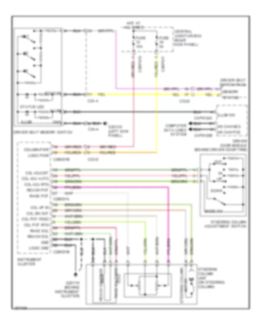 https://portal-diagnostov.com/license.html
Automotive Electricians Portal FZCO
Automotive Electricians Portal FZCO
https://portal-diagnostov.com/license.html
https://portal-diagnostov.com/license.html
Automotive Electricians Portal FZCO
Automotive Electricians Portal FZCOList of elements for Steering Column Memory Wiring Diagram for Jaguar XF 2011:
- C23-d
- C2mc01a
- C2mc01b
- C33-d
- C3a-a
- C3bp01d
- C3bp01f
- Capw02a
- Capw02b
- Central junction box (right kick panel)
- Col adj auto
- Col adj rtn
- Col adjust
- Col dn out
- Col pot feed
- Col pot rtn
- Col up in
- Column pwr
- Computer data lines system
- Down
- Driver door module (behind driver door trim)
- Driver seat memory switch
- Driver seat switch pack
- Fuse 10a
- Fuse 5a
- G2d115 (behind instrument cluster)
- G3d133 (left kick panel)
- Gnd
- Hot at all times
- Hs can pos
- Illum
- Illum sw
- Instrument cluster
- Logic gnd
- Logic pwr
- Memory
- Mode sw
- Out
- Rake pot
- Rake sol
- Rake solenoid
- Reach pot
- Reach sol
- Reach solenoid
- Set
- Status
- Status led
- Steering column adjustment switch
- Steering column motor
- Steering column unit (on steering column)
NAVIGATION
Navigation Wiring Diagram for Jaguar XF 2011
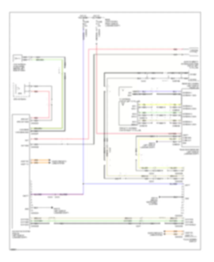 https://portal-diagnostov.com/license.html
Automotive Electricians Portal FZCO
Automotive Electricians Portal FZCO
https://portal-diagnostov.com/license.html
https://portal-diagnostov.com/license.html
Automotive Electricians Portal FZCO
Automotive Electricians Portal FZCOList of elements for Navigation Wiring Diagram for Jaguar XF 2011:
- Am/fm diversity antenna amplifier (top of left "c" pillar)
- Ant
- Ant gnd
- Antenna 1
- Antenna 1 scn
- Antenna 2
- Antenna 2 scn
- Antenna 3
- Antenna 3 scn
- Antenna 4
- Antenna 4 scn
- Batt
- C23-f
- C23-g
- C23-k
- C2mc02a
- C2mc02b
- C2mc02c
- C2mc02d
- C2mc02e
- C44-b
- C44-d
- C44-m
- C44-n
- C4bp01d
- C4bp01h
- C4me31a
- C4me31b
- C4me33a
- C4me33b
- C4me33c
- C4mn23a
- C4mn23b
- C4mn23c
- C4mn23e
- C4mn23f
- C4mp19b
- Computer data lines system
- Cvbs gnd
- Cvbs out
- Fuse 10a
- G2d116 (behind instrument cluster)
- G4d172 (left side of luggage compt)
- Gnd
- Gps
- Gps ant
- Gps ant gnd
- Gps antenna
- Gvif pos
- Gvif scn
- Gvif shield
- Hot at all times
- Most rx
- Most tx
- Navigation system module (left side of luggage compt)
- Nca
- Rear junction box (right side of luggage compt)
- Rearview camera (left side of trunk lid)
- Red
- Scn
- Scn 1
- Scn 2
- Scn 3
- Sig
- Sig 1
- Sig 2
- Sig 3
- Television receiver (left side of luggage compt)
- Touch screen display
- Triple tv antenna (top of right "c" pillar)
- Tv antenna (top of left "c" pillar)
- Vbatt
- Vcis antenna (if equipped) (behind left side of dash)
- Vics sens
- Vics sens gnd
- Vics/tmc
- Vid pos
Parking Assistant Wiring Diagram for Jaguar XF 2011
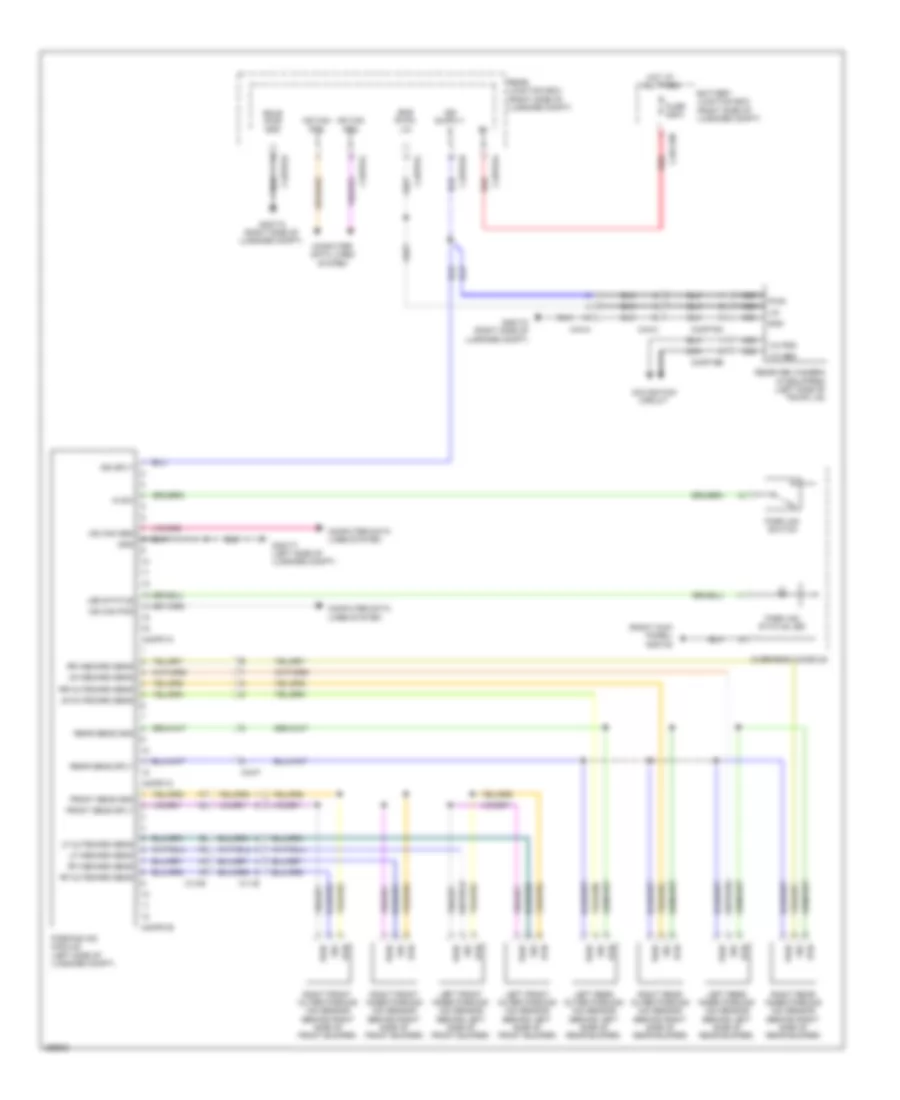 https://portal-diagnostov.com/license.html
Automotive Electricians Portal FZCO
Automotive Electricians Portal FZCO
https://portal-diagnostov.com/license.html
https://portal-diagnostov.com/license.html
Automotive Electricians Portal FZCO
Automotive Electricians Portal FZCOList of elements for Parking Assistant Wiring Diagram for Jaguar XF 2011:
- (right kick panel) g3d138
- Battery junction box (right side of luggage compt)
- Bms rvpa lin
- C11-e
- C13-b
- C44-a
- C44-c
- C44-f
- C4bf10b
- C4bp01a
- C4bp01d
- C4bp01h
- C4bp01l
- C4mp01a
- C4mp01b
- C4mp01c
- C4mp19a
- C4mp19b
- Computer data lines system
- Front sens gnd
- Front sens sply
- Fuse 250a
- G4d171 (left side of luggage compt)
- G4d173 (right side of luggage compt)
- Gnd
- Hot at all times
- Ign sply
- In sw
- Led status
- Left front inner parking aid sensor (behind left side of front bumper)
- Left front outer parking aid sensor (behind left side of front bumper)
- Left rear inner parking aid sensor (behind left side of rear bumper)
- Left rear outer parking aid sensor (behind left side of rear bumper)
- Lf inboard sens
- Lf outboard sens
- Lin
- Lr inboard sens
- Lr outboard sens
- Ms can pos
- Navigation circuit
- Nca
- Overhead console
- Park aid status led
- Park aid switch
- Parking aid module (left side of luggage compt)
- Pwr
- Rear junction box (right side of luggage compt)
- Rear sens gnd
- Rear sens sply
- Rearview camera (if equipped) (left side of trunk lid)
- Red
- Rf inboard sens
- Rf outboard sens
- Right front inner parking aid sensor (behind right side of front bumper)
- Right front outer parking aid sensor (behind right side of front bumper)
- Right rear inner parking aid sensor (behind right side of rear bumper)
- Right rear outer parking aid sensor (behind right side of rear bumper)
- Rr inboard sens
- Rr outboard sens
- Rsjb pwr gnd
- Rtn
- Sig
- Vic pos
POWER DISTRIBUTION
Power Distribution Wiring Diagram (1 of 5) for Jaguar XF 2011
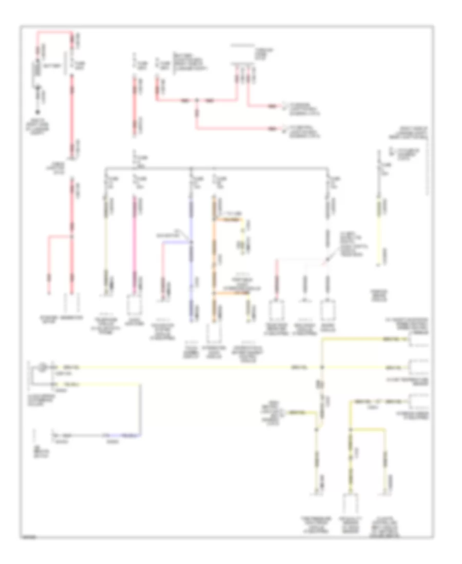 https://portal-diagnostov.com/license.html
Automotive Electricians Portal FZCO
Automotive Electricians Portal FZCO
https://portal-diagnostov.com/license.html
https://portal-diagnostov.com/license.html
Automotive Electricians Portal FZCO
Automotive Electricians Portal FZCOList of elements for Power Distribution Wiring Diagram (1 of 5) for Jaguar XF 2011:
- (right side of luggage compt) rear junction box
- (w/ adaptive stop/go speed control) speed control module
- Air quality sensor (w/ smog sensor)
- Audio amplifier
- Battery junction box (right side of luggage compt)
- C13-d
- C1dc11b
- C1dc12a
- C23-d
- C2mc02a
- C2me03a
- C2mt01a
- C2r115a
- C33-a
- C3dc11a
- C3hs03b
- C3mc39b
- C3me17a
- C3mm01a
- C49-a
- C4bf10b
- C4bf10c
- C4bp01b
- C4bp01c
- C4bp01d
- C4bp01h
- C4bpo1a
- C4cb01b
- C4d101
- C4dc02a battery
- C4df10a
- C4me22a
- C4mn23a
- Cable junction stud
- Cidc12b
- Climate controlled seat module (w/ heated & cooled seats)
- Clock spring (in steering column)
- From central junction box t (diagram 2 of 5)
- Fuse 10a
- Fuse 15a
- Fuse 250a
- Fuse 30a
- Fuse 400a
- Fuse 50a
- Fuse 5a
- G4d178 (right side of luggage compt)
- Generator
- Iboc radio module (if equipped)
- Ice remote switch
- In car temperature sensor
- Information & entertainment control module
- Integrated audio module
- Interior mirror (if equipped)
- Navigation system module (if equipped)
- Parking brake module
- Portable audio interface module (w/ usb)
- Red
- Sa004
- Sdars module
- Starter motor
- Sw002
- Sw003
- Television receiver (if equipped)
- Through panel stud
- Tire pressure monitoring module (if equipped)
- To central junction box (diagram 3 of 5)
- To engine junction box (diagram 4 of 5)
- To fuse 29 (diagram 2 of 5)
- Touch screen display
- W/ iboc, satellite digital audio, digital audio & television
- W/ navigation
- W/ usb
Power Distribution Wiring Diagram (2 of 5) for Jaguar XF 2011
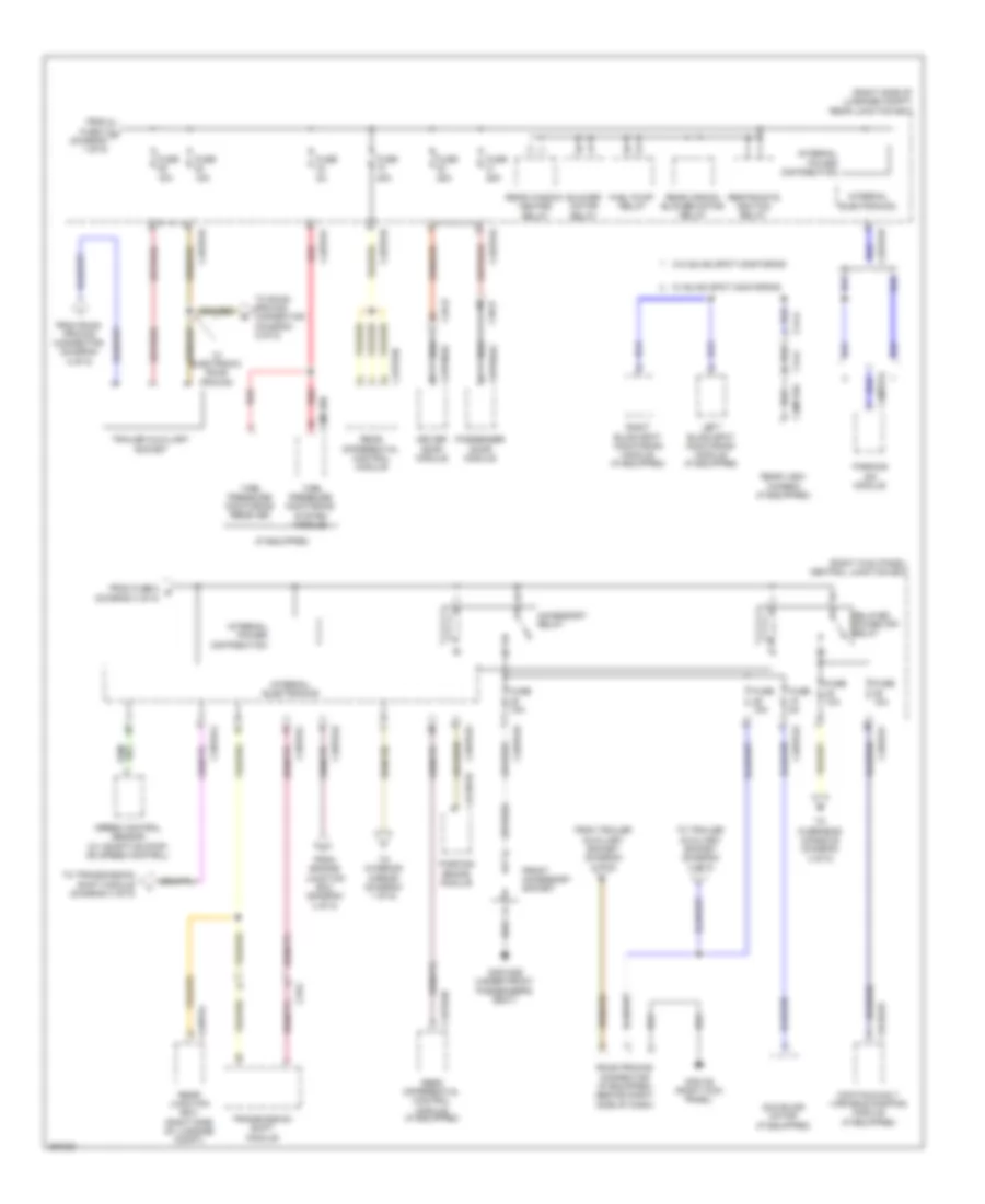 https://portal-diagnostov.com/license.html
Automotive Electricians Portal FZCO
Automotive Electricians Portal FZCO
https://portal-diagnostov.com/license.html
https://portal-diagnostov.com/license.html
Automotive Electricians Portal FZCO
Automotive Electricians Portal FZCOList of elements for Power Distribution Wiring Diagram (2 of 5) for Jaguar XF 2011:
- (if equipped)
- (right kick panel) central junction box
- (right side of luggage compt) rear junction box
- Accessory relay
- Blower motor relay
- C33-c
- C3a-b
- C3b-b
- C3bp01b
- C3bp01d
- C3bp01e
- C3bp01f
- C3bp01h
- C3bp01j
- C3bp01l
- C3cd01b
- C3mc39b
- C44-a
- C44-c
- C4bp01b
- C4bp01d
- C4bp01f
- C4bp01h
- C4bp01l
- C4cb01b
- C4et63b
- C4mp01a
- C4mp19a
- Capw02a
- Cbpw04a
- Continuously variable damping module (if equipped)
- Delayed power off relay
- Driver door module
- From engine junction box (diagram 4 of 5)
- From fuse 2 c (diagram 1 of 5)
- From fuse 8 g (diagram 3 of 5)
- From road pricing connector (diagram 2 of 5)
- From trailer auxiliary socket (diagram 2 of 5)
- Front accessory socket
- Fuel pump relay
- Fuse 10a
- Fuse 15a
- Fuse 25a
- Fuse 40a
- Fuse 5a
- G3d138 (right kick panel)
- G3d183b (under front passenger's seat)
- Internal electronics
- Internal power distribution
- Left blind spot monitoring module (if equipped)
- Parking aid module
- Parking brake module
- Passenger door module
- Rear aircon blower motor relay
- Rear differential control module
- Rear differential control module (if equipped)
- Rear junction box (right side of luggage compt)
- Rear view camera (if equipped)
- Rear window heated relay
- Red
- Restraints ignition relay
- Right blind spot monitoring module (if equipped)
- Road pricing connector (if equipped) (behind right side of dash)
- Speed control sensor (w/ adaptive stop/ go speed control)
- Sun blind motor (if equipped)
- Tire pressure monitoring receiver
- Tire pressure monitoring system module
- To interior mirror (diagram 1 of 5)
- To overhead console (diagram 4 of 5)
- To road pricing connector (diagram 2 of 5)
- To trailer auxiliary socket (diagram 2 of 5)
- To transmission shift module (diagram 4 of 5)
- Trailer auxiliary socket
- Transmission shift module
- W/ blind spot monitoring
- W/ electronic road pricing
- W/o blind spot monitoring
Power Distribution Wiring Diagram (3 of 5) for Jaguar XF 2011
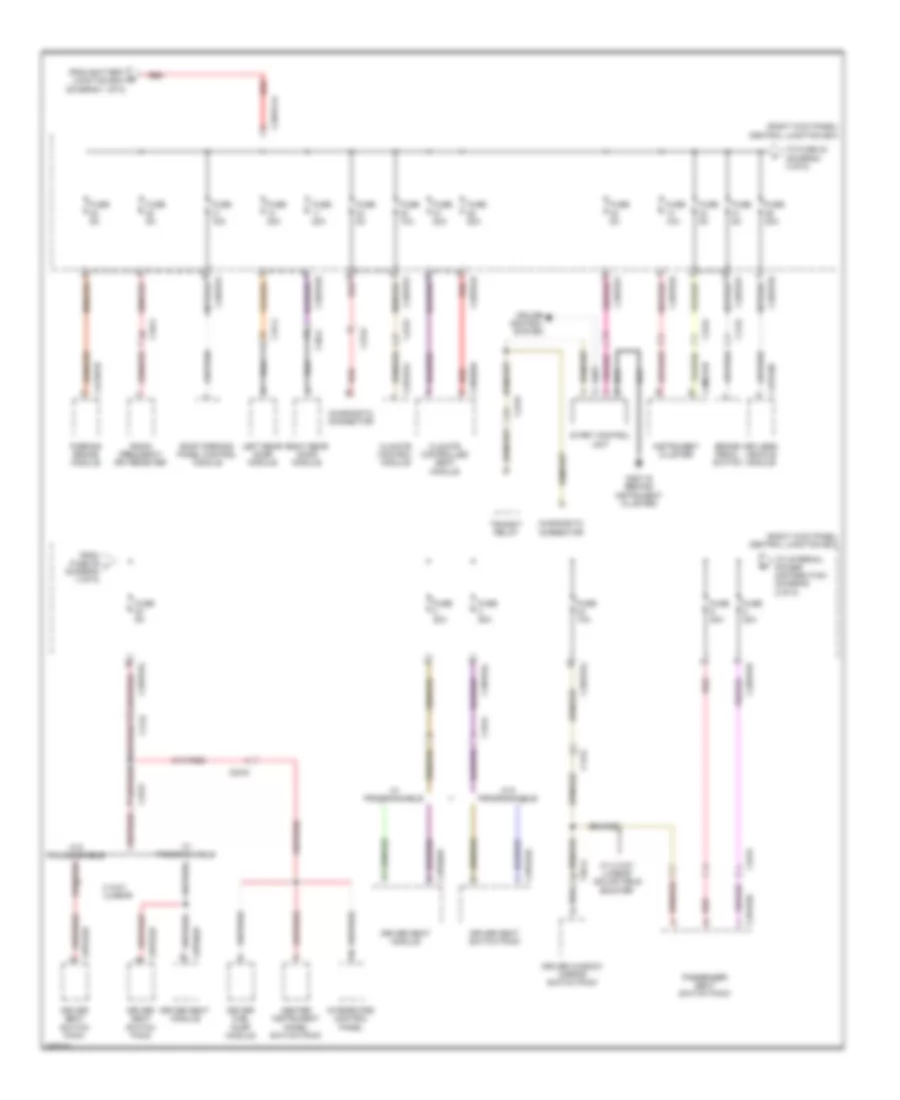 https://portal-diagnostov.com/license.html
Automotive Electricians Portal FZCO
Automotive Electricians Portal FZCO
https://portal-diagnostov.com/license.html
https://portal-diagnostov.com/license.html
Automotive Electricians Portal FZCO
Automotive Electricians Portal FZCOList of elements for Power Distribution Wiring Diagram (3 of 5) for Jaguar XF 2011:
- (right kick panel) central junction box
- 2 way lumbar
- Brake pedal switch
- C13-d
- C13-e
- C23-d
- C23-r
- C2h101a
- C2mc01b
- C33-e
- C33-h
- C37-a
- C38-a
- C3a-a
- C3bp01b
- C3bp01c
- C3bp01d
- C3bp01f
- C3bp01g
- C3bpo1a
- C3hs03a
- C3ps02d
- C3ps22d
- C3ps22e
- C3ps32c
- C49-a
- C4cb01b
- C4pk28c
- Center instrument panel switch pack
- Climate control module
- Climate controlled seat module
- Cruise control system
- Diagnostic connector
- Driver fuel pump module
- Driver seat module
- Driver seat switch pack
- Driver window mirror switch pack
- From battery b junction box (diagram 1 of 5)
- From fuse 29 f (diagram 3 of 5)
- Fuse 10a
- Fuse 15a
- Fuse 20a
- Fuse 5a
- G2d115 (behind instrument cluster)
- Instrument cluster
- Integrated control panel
- Keyless vehicle module
- Left rear door module
- Parking brake module
- Passenger seat switch pack
- Radio frequency (rf) receiver
- Red
- Right rear door module
- Roof opening panel control module
- Start control unit
- To fuse 23 (diagram 3 of 5)
- To internal power distribution (diagram 2 of 5)
- Transit relay
- W/ 2 way lumbar adjustable bolster
- W/ programmable
- W/o programmable
Power Distribution Wiring Diagram (4 of 5) for Jaguar XF 2011
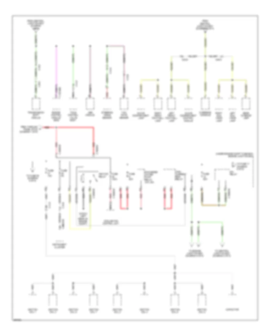 https://portal-diagnostov.com/license.html
Automotive Electricians Portal FZCO
Automotive Electricians Portal FZCO
https://portal-diagnostov.com/license.html
https://portal-diagnostov.com/license.html
Automotive Electricians Portal FZCO
Automotive Electricians Portal FZCOList of elements for Power Distribution Wiring Diagram (4 of 5) for Jaguar XF 2011:
- (under engine compt fuse box) engine junction box
- Abs module
- C11-p
- C12-a
- C12-b
- C13-b
- C13-c
- C1bb01b
- C1bb01c
- C1bb01d
- C1bb01e
- C1e120a
- C23-d
- C2mc01b
- C33-c
- C49-a
- Capacitor
- Cooling fan control unit
- Engine control module (ecm)
- From central junction box (diagram 2 of 4)
- From central junction box (diagram 2 of 5)
- From through a panel stud (diagram 1 of 5)
- Fuse 100a
- Fuse 15a
- Fuse 50a
- Fuse 5a
- G1d123 (left rear of engine compt)
- Glove compartment control module
- Glove compartment lamp
- High current ems relay
- Ignition coil 1
- Ignition coil 2
- Ignition coil 3
- Ignition coil 4
- Ignition coil 5
- Ignition coil 6
- Ignition coil 7
- Ignition coil 8
- Ignition relay
- Instrument cluster
- Left front footwell lamp
- Left sun visor lamp
- Nca
- Overhead console
- Rear interior lamp
- Red
- Right front footwell lamp
- Right sun visor lamp
- S/charged water pump relay (5.0l sc)
- Sia relay
- Steering angle sensor
- Tcm & control valve body
- To central junction box (diagram 2 of 5)
- To engine junction box (diagram 5 of 5)
- To fuse 17 (diagram 5 of 5)
- To fuse 39 (diagram 5 of 5)
- Transmission shift module
- Yaw rate sensor
Power Distribution Wiring Diagram (5 of 5) for Jaguar XF 2011
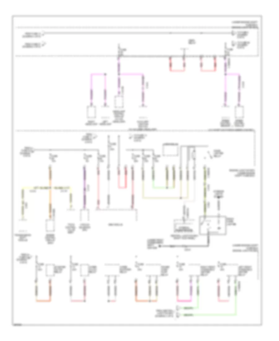 https://portal-diagnostov.com/license.html
Automotive Electricians Portal FZCO
Automotive Electricians Portal FZCO
https://portal-diagnostov.com/license.html
https://portal-diagnostov.com/license.html
Automotive Electricians Portal FZCO
Automotive Electricians Portal FZCOList of elements for Power Distribution Wiring Diagram (5 of 5) for Jaguar XF 2011:
- (under engine compt fuse box) engine junction box
- (under front passenger's seat) g3d183b
- (w/ adaptive stop/go speed control)
- Abs module
- Auxiliary lighting switch (w/ halogen headlamp)
- C11-p
- C12-a
- C12-b
- C13-c
- C13-d
- C1bb01b
- C1e120a
- C1lf39
- C33-c
- C3bpo1g
- Central junction box (right kick panel)
- Cigar lighter relay
- Engine control module (ecm)
- Engine junction box (under engine compt fuse box)
- From central junction box (diagram 4 of 5)
- From fuse 12 k (diagram 4 of 5)
- From fuse 17 p (diagram 5 of 5)
- From fuse 24 q (diagram 5 of 5)
- From fuse 37 o (diagram 4 of 5)
- From fuse 5 r (diagram 5 of 5)
- Front cigar lighter
- Fuse 10a
- Fuse 15a
- Fuse 25a
- Fuse 30a
- Fuse 40a
- Fuse 5a
- Headlamp control module (w/ hid headlamp)
- Hego relay
- Horn relay
- Interior lights system
- Internal electronics
- Left front windshield heater relay
- Left headlamp
- Power wash pump relay
- Red
- Right front windshield heater relay
- Right headlamp
- Speed control module
- Speed control sensor
- Starter motor relay
- Tcm & control valve body
- To fuse 14 (diagram 5 of 5)
- To fuse 26 (diagram 5 of 5)
- To fuse 5 (diagram 5 of 5)
- Transmission shift module
- Vacuum solenoid (sai)
- Wiper hi/low relay
- Wiper run/park relay
POWER DOOR LOCKS
Door Lock Wiring Diagram (1 of 2) for Jaguar XF 2011
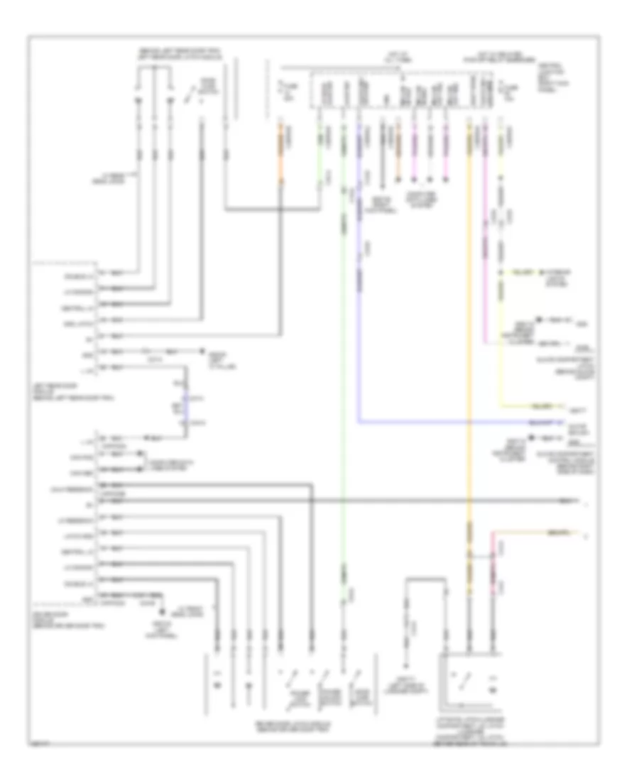 https://portal-diagnostov.com/license.html
Automotive Electricians Portal FZCO
Automotive Electricians Portal FZCO
https://portal-diagnostov.com/license.html
https://portal-diagnostov.com/license.html
Automotive Electricians Portal FZCO
Automotive Electricians Portal FZCOList of elements for Door Lock Wiring Diagram (1 of 2) for Jaguar XF 2011:
- (behind left rear door trim) left rear door latch module
- Ajar sw
- Boot open
- C13-a
- C13-d
- C23-d
- C23-r
- C37-a
- C3a-a
- C3a-b
- C3bp01b
- C3bp01d
- C3bp01f
- C3bp01j
- C3bp01k
- C44-a
- C44-c
- Can pos
- Capw02a
- Capw02b
- Central junction box (right kick panel)
- Central lk
- Computer data lines system
- Door ajar switch
- Double lk
- Driver door latch module (behind driver door trim)
- Driver door module (behind driver door trim)
- Fuse 10a
- Fuse 20a
- G2d115 (behind instrument cluster)
- G3d133 (left kick panel)
- G3d138 (right kick panel)
- G3d161 (left "c" pillar)
- G4d171 (left side of luggage compt)
- Glove box lock-sw
- Glove box-sw
- Glove compartment control module (behind right side of dash)
- Glove compartment latch (behind glove compt)
- Gnd
- Gnd latch
- Hot at all times
- Hot w/ delayed pwr off relay energized
- Interior lights system
- L lin
- Latch gnd
- Left rear door module (behind left rear door trim)
- Liftgate latch/luggage compartment lid latch (luggage compartment lid latch: center rear of trunk lid)
- Lk common
- Lk feedback
- Lock mtr glove box
- Lr door ajar sw
- Ms can in pos
- Ms can out pos
- Power lock switch
- Power unlock switch
- Pwr
- Unlk feedback
- Vbatt
- W/ front dead l0cks
- W/ rear dead l0cks
Door Lock Wiring Diagram (2 of 2) for Jaguar XF 2011
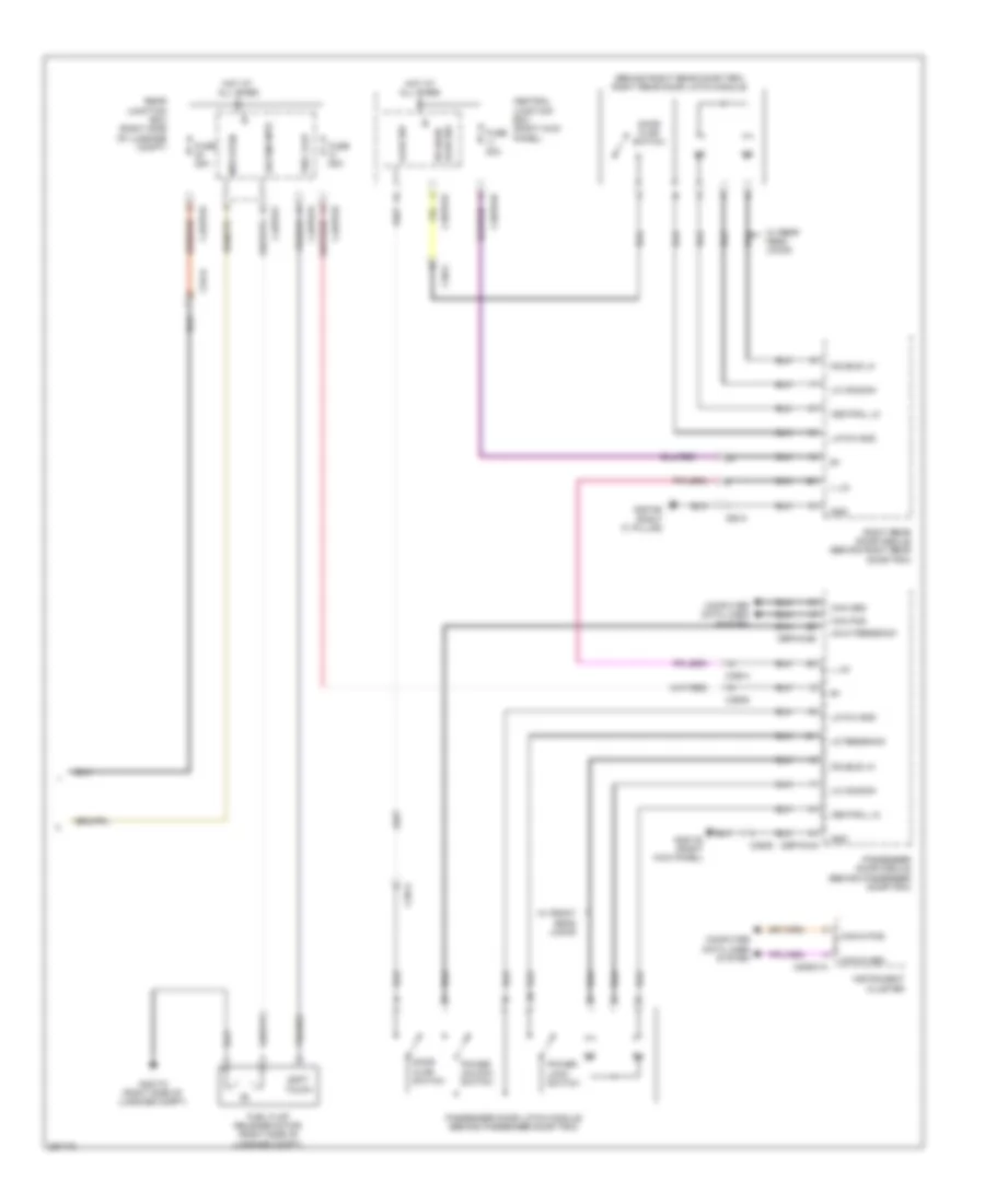 https://portal-diagnostov.com/license.html
Automotive Electricians Portal FZCO
Automotive Electricians Portal FZCO
https://portal-diagnostov.com/license.html
https://portal-diagnostov.com/license.html
Automotive Electricians Portal FZCO
Automotive Electricians Portal FZCOList of elements for Door Lock Wiring Diagram (2 of 2) for Jaguar XF 2011:
- (behind right rear door trim) right rear door latch module
- Ajar sw
- C2mc01a
- C38-a
- C3a-b
- C3b-a
- C3b-b
- C3bp01b
- C3bp01k
- C4bp01d
- C4bp01f
- C4bp01k
- Can in pos
- Can pos
- Cbpw04a
- Cbpw04b
- Central junction box (right kick panel)
- Central lk
- Computer data lines system
- Door ajar switch
- Double lk
- Fuel flap
- Fuel flap release motor (right side of luggage compt)
- Fuse 20a
- Fuse 25a
- G3d138 (right kick panel)
- G3d162 (right "c" pillar)
- G4d173 (right side of luggage compt)
- Gnd
- Hot at all times
- Instrument cluster
- L lin
- Latch gnd
- Lk common
- Lk feedback
- Locking mtr
- Mtr open
- Passenger door latch module (behind passenger door trim)
- Passenger door module (behind passenger door trim)
- Power lock switch
- Power unlock switch
- Rear junction box (right side of luggage compt)
- Right rear door module (behind right rear door trim)
- Rr door ajar sw
- Soft touch
- Unlk feedback
- W/ front dead locks
- W/ rear dead l0cks
Keyless Entry Wiring Diagram (1 of 2) for Jaguar XF 2011
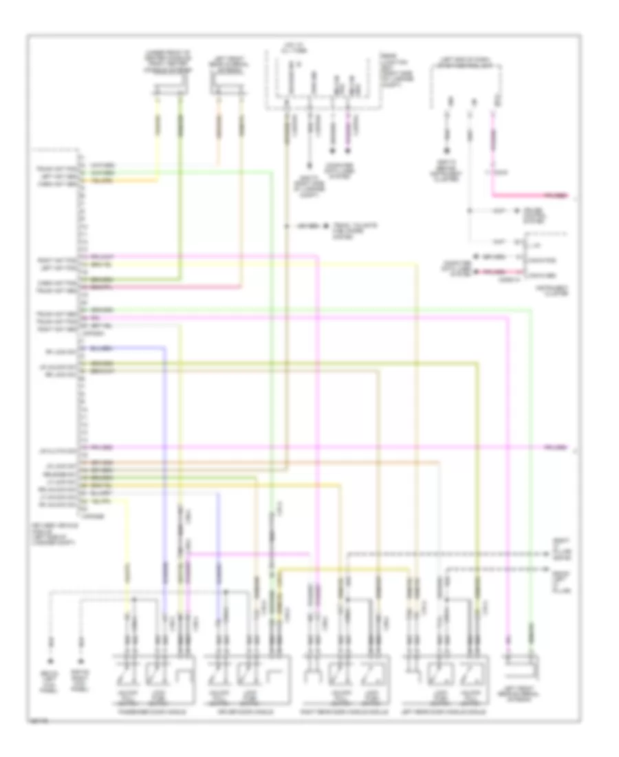 https://portal-diagnostov.com/license.html
Automotive Electricians Portal FZCO
Automotive Electricians Portal FZCO
https://portal-diagnostov.com/license.html
https://portal-diagnostov.com/license.html
Automotive Electricians Portal FZCO
Automotive Electricians Portal FZCOList of elements for Keyless Entry Wiring Diagram (1 of 2) for Jaguar XF 2011:
- (left end of dash) start control unit
- (right "c" pillar) g3d162
- (under front of center console) front center console antenna
- C23-d
- C2mc01a
- C37-a
- C38-a
- C3a-a
- C3b-a
- C4bp01d
- C4bp01k
- C4bp01l
- C4pk28a
- C4pk28e
- Cabin ant pos
- Can in pos
- Computer data lines system
- Cruise control system
- Driver door handle
- G2d115 (behind instrument cluster)
- G3d133 (left kick panel)
- G3d138 (right kick panel)
- G3d161 (left "c" pillar)
- G4d173 (right side of luggage compt)
- Gnd
- Hot at all times
- Instrument cluster
- Keyless vehicle module (left side of luggage compt)
- L lin
- Left ant pos
- Left front rear external antenna
- Left front rear internal antenna
- Left rear door handle module
- Lf lock sw
- Lf unlock sw
- Lin
- Lock push switch
- Lr clutch sw
- Lr lock sw
- Lr unlock sw
- Ms can pos
- Passenger door handle
- Pwr gnd
- Rear junction box (right side of luggage compt)
- Release sw
- Rf lock sw
- Rf unlock sw
- Right ant pos
- Right rear door handle module
- Rr lock sw
- Rr unlock sw
- Sply
- Trunk ant pos
- Trunk, tailgate fuel doors system
- Unlock pull switch
Keyless Entry Wiring Diagram (2 of 2) for Jaguar XF 2011
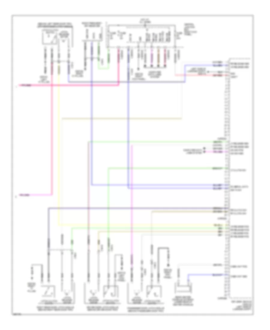 https://portal-diagnostov.com/license.html
Automotive Electricians Portal FZCO
Automotive Electricians Portal FZCO
https://portal-diagnostov.com/license.html
https://portal-diagnostov.com/license.html
Automotive Electricians Portal FZCO
Automotive Electricians Portal FZCOList of elements for Keyless Entry Wiring Diagram (2 of 2) for Jaguar XF 2011:
- (behind left rear door trim) left rear door latch module
- (left side of luggage compt) g4d172
- C13-e
- C37-a
- C38-a
- C3a-a
- C3a-b
- C3b-a
- C3b-b
- C3bp01b
- C3bp01d
- C3bp01f
- C3bp01j
- C3bp01k
- C49-a
- C4pk28b
- C4pk28c
- C4pk28d
- Cabin ant pos
- Central junction box (right kick panel)
- Computer data lines system
- Data
- Driver door latch module (behind driver door trim)
- Fuse 20a
- Fuse 5a
- G3d133 (left kick panel)
- G3d138 (right kick panel)
- G3d161 (left "c" pillar)
- G3d162 (right "c" pillar)
- Gnd
- Gnd rtn
- Hot at all times
- Key in
- Key in sw
- Keyless vehicle module (left side of luggage compt)
- Latch clutch switch
- Latch release motor
- Lf clutch sw
- Lf release pos
- Lr release pos
- Ms can in pos
- Ms can out pos
- Ms can pos
- Passenger door latch module (behind passenger door trim)
- Pwr
- Radio frequency (rf) receiver
- Rear center console antenna (under rear of center console)
- Rf clutch sw
- Rf release pos
- Right rear door latch module (behind right rear door trim)
- Rr clutch sw
- Rr release pos
- Rx serial data
- Vbatt
POWER MIRRORS
Power Mirrors Wiring Diagram for Jaguar XF 2011
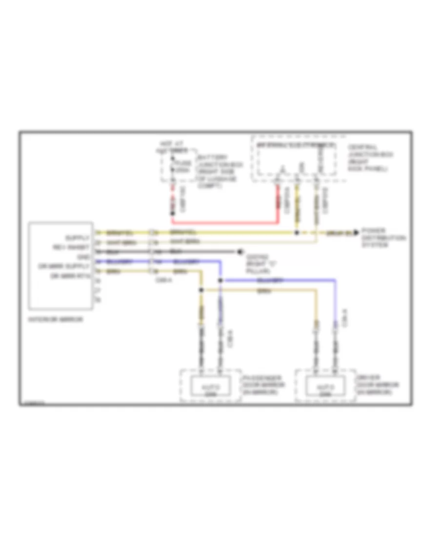 https://portal-diagnostov.com/license.html
Automotive Electricians Portal FZCO
Automotive Electricians Portal FZCO
https://portal-diagnostov.com/license.html
https://portal-diagnostov.com/license.html
Automotive Electricians Portal FZCO
Automotive Electricians Portal FZCOList of elements for Power Mirrors Wiring Diagram for Jaguar XF 2011:
- Auto dim
- Battery junction box (right side of luggage compt)
- C3a-a
- C3b-a
- C3bp01a
- C3bp01e
- C49-a
- C4bf10c
- Central junction box (right kick panel)
- Dr mirr rtn
- Driver door mirror (in mirror)
- Fuse 250a
- G3d162 (right "c" pillar)
- Gnd
- Hot at all times
- Ign
- Interior mirror
- Internal electronics
- Passenger door mirror (in mirror)
- Power distribution system
- Red
- Rev inhibit
- Reverse
POWER SEATS
Climate Control Seats Wiring Diagram for Jaguar XF 2011
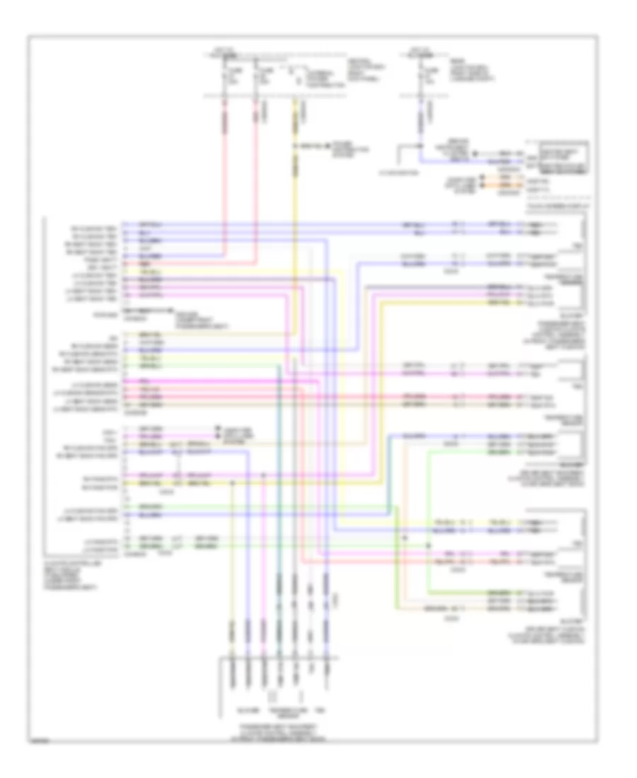 https://portal-diagnostov.com/license.html
Automotive Electricians Portal FZCO
Automotive Electricians Portal FZCO
https://portal-diagnostov.com/license.html
https://portal-diagnostov.com/license.html
Automotive Electricians Portal FZCO
Automotive Electricians Portal FZCOList of elements for Climate Control Seats Wiring Diagram for Jaguar XF 2011:
- (behind instrument cluster) g2d116
- Batt
- Blower
- Blw pwr
- Blw rtn
- Blw spd
- C2mc02a
- C2mc02c
- C33-d
- C33-g
- C3bp01d
- C3bp01e
- C3hs03a
- C3hs03b
- C3hs03c
- C4bp01d
- Can +
- Can -
- Central junction box (right kick panel)
- Climate controlled seat module (if equipped) (under front passenger's seat)
- Computer data lines system
- Driver seat backrest climate control assembly (in driver's seat back)
- Driver seat cushion climate control assembly (in driver's seat cushion)
- Drv vbatt
- Fuse 10a
- Fuse 20a
- G3d183b (under front passenger's seat)
- Gnd
- Heated seat switches
- Heated/cooled seat switches
- Hot at all times
- Ign
- Internal power distribution
- Lh cushion fan spd
- Lh cushion sens
- Lh cushion sensor rtn
- Lh cushion ted+
- Lh cushion ted-
- Lh fans pwr
- Lh fans rtn
- Lh seat back fan spd
- Lh seat back sens
- Lh seat back sens rtn
- Lh seat back ted+
- Lh seat back ted-
- Most-rx
- Most-tx
- Pass vbatt
- Passenger seat backrest climate control assembly (in front passenger's seat back)
- Passenger seat cushion climate control assembly (in front passenger's seat cushion)
- Power distribution system
- Pwr gnd
- Rear junction box (right side of luggage compt)
- Red
- Rh cushion fan spd
- Rh cushion sens
- Rh cushion sens rtn
- Rh cushion ted+
- Rh cushion ted-
- Rh fans pwr
- Rh fans rtn
- Rh seat back fan spd
- Rh seat back sens
- Rh seat back sens rtn
- Rh seat back ted+
- Rh seat back ted-
- Ted
- Ted+
- Ted-
- Temp rtn
- Temp sig
- Temperature sensor
- Touch screen display
- W/ navigation
Heated Seats Wiring Diagram for Jaguar XF 2011
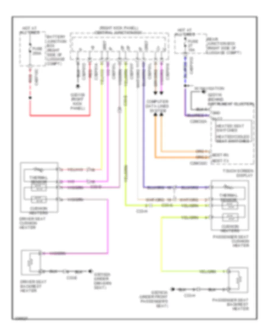 https://portal-diagnostov.com/license.html
Automotive Electricians Portal FZCO
Automotive Electricians Portal FZCO
https://portal-diagnostov.com/license.html
https://portal-diagnostov.com/license.html
Automotive Electricians Portal FZCO
Automotive Electricians Portal FZCOList of elements for Heated Seats Wiring Diagram for Jaguar XF 2011:
- (right kick panel) central junction box
- Batt
- Battery junction box (right side of luggage compt)
- C2mc02a
- C2mc02c
- C33-d
- C33-e
- C33-g
- C33-h
- C3bp01a
- C3bp01d
- C3bp01f
- C3bp01k
- C3bp01l
- C4bf10c
- C4bp01d
- Computer data lines system
- Cushion heaters
- Driver seat backrest heater
- Driver seat cushion heater
- Fuse 10a
- Fuse 250a
- G2d116 (behind instrument cluster)
- G3d138 (right kick panel)
- G3d182a (under driver's seat)
- G3d183a (under front passenger's seat)
- Gnd
- Gref
- Heated seat switches
- Heated/cooled seat switches
- Hot at all times
- Most-rx
- Most-tx
- Passenger seat backrest heater
- Passenger seat cushion heater
- Rear junction box (right side of luggage compt)
- Red
- Thermal sensor
- Touch screen display
- W/ navigation
Heated Steering Wheel Wiring Diagram for Jaguar XF 2011
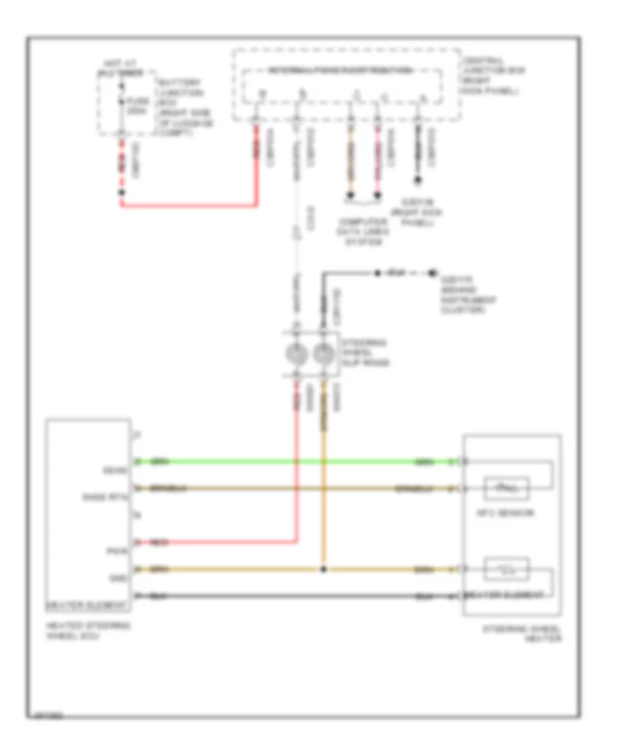 https://portal-diagnostov.com/license.html
Automotive Electricians Portal FZCO
Automotive Electricians Portal FZCO
https://portal-diagnostov.com/license.html
https://portal-diagnostov.com/license.html
Automotive Electricians Portal FZCO
Automotive Electricians Portal FZCOList of elements for Heated Steering Wheel Wiring Diagram for Jaguar XF 2011:
- Battery junction box (right side of luggage compt)
- C23-d
- C2r115d
- C3bp01a
- C3bp01d
- C3bp01k
- C4bf10c
- Central junction box (right kick panel)
- Computer data lines system
- Fuse 250a
- G2d115 (behind instrument cluster)
- G3d138 (right kick panel)
- Gnd
- Heated steering wheel ecu
- Heater element
- Hot at all times
- Internal power distribution
- Ntc sensor
- Pwr
- Red
- Sens
- Snse rtn
- Steering wheel heater
- Steering wheel slip rings
- Sw001
- Sw015
Passenger Power Seat Wiring Diagram for Jaguar XF 2011
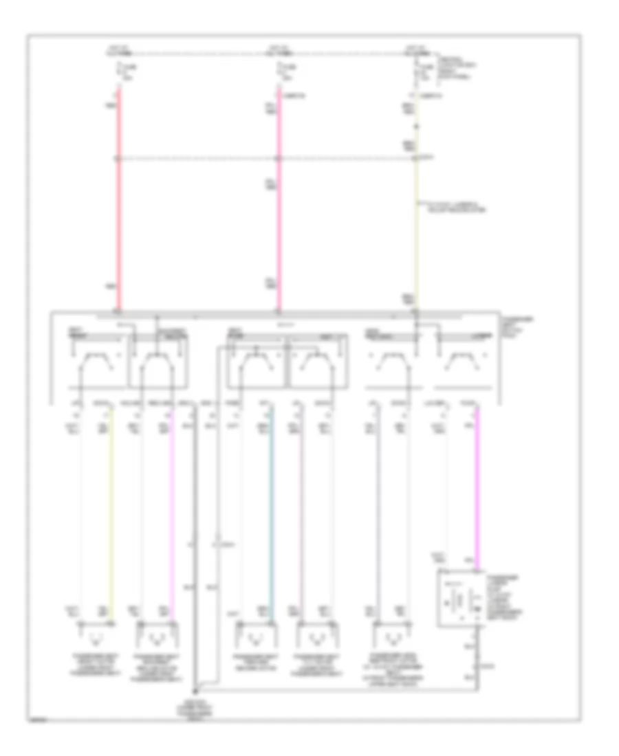 https://portal-diagnostov.com/license.html
Automotive Electricians Portal FZCO
Automotive Electricians Portal FZCO
https://portal-diagnostov.com/license.html
https://portal-diagnostov.com/license.html
Automotive Electricians Portal FZCO
Automotive Electricians Portal FZCOList of elements for Passenger Power Seat Wiring Diagram for Jaguar XF 2011:
- Aft
- Backrest recline
- C33-g
- C33-h
- C3bp01b
- C3bp01g
- Central junction box (right kick panel)
- Down
- Fore
- Fuse 10a
- Fuse 20a
- G3d183a (under front passenger's seat)
- Gnd 1
- Gnd 2
- Head restraint
- Hot at all times
- Incline
- Lum def
- Lumbar
- Passenger head restraint motor (w/ 12-way passenger seat) (in front passenger's upper seat back)
- Passenger lumbar pump (w/ 2-way lumbar) (in front passenger's seat back)
- Passenger seat backrest recline motor (under front passenger's seat)
- Passenger seat forward reward motor
- Passenger seat height motor (under front passenger's seat)
- Passenger seat switch pack
- Passenger seat tilt motor (under front passenger's seat)
- Pump
- Recline
- Red
- Seat height
- Seat slide
- Seat tilt
- W/ 2-way lumbar & adjustable bolster
Passenger Seat Lumbar/Bolster Wiring Diagram for Jaguar XF 2011
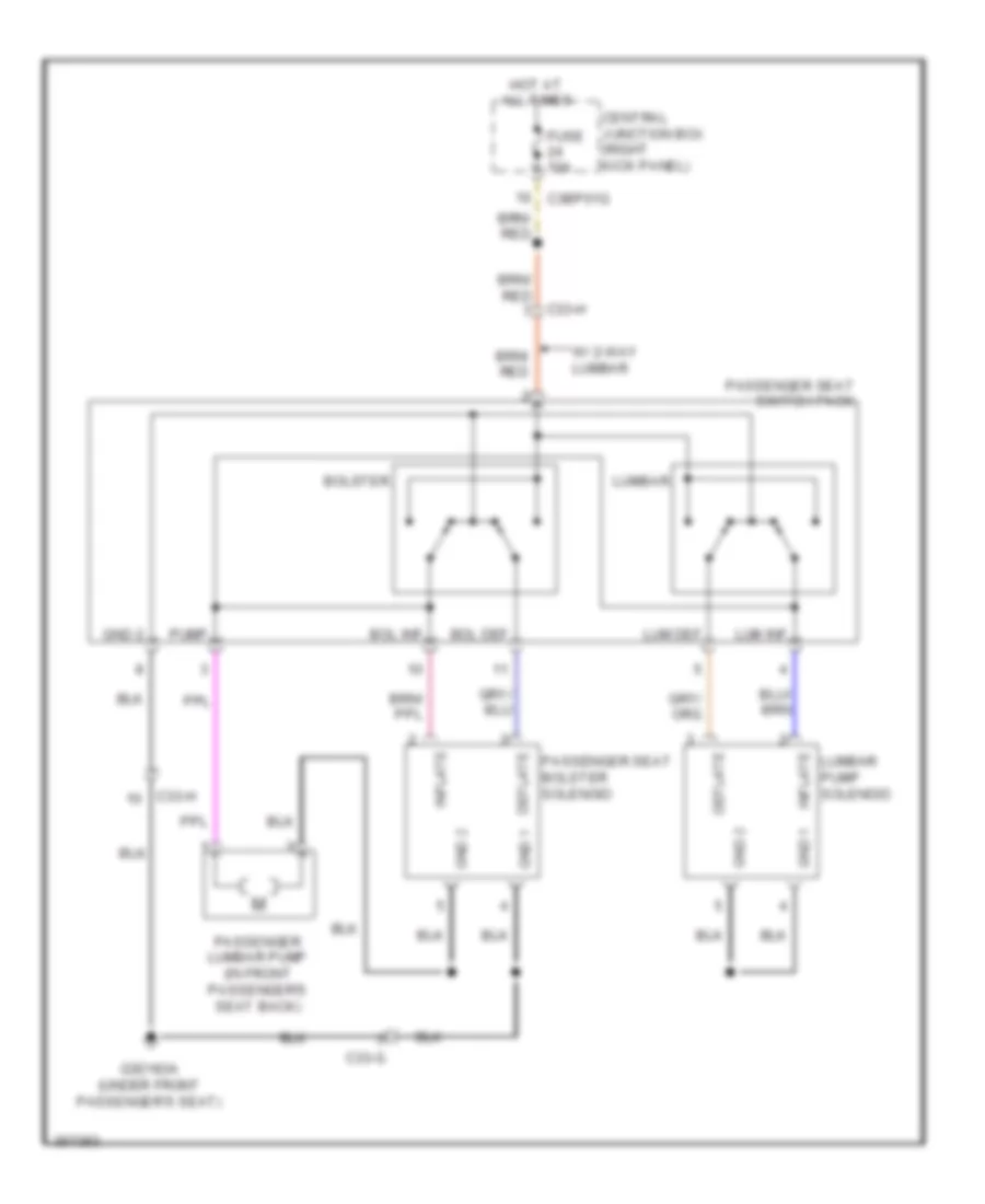 https://portal-diagnostov.com/license.html
Automotive Electricians Portal FZCO
Automotive Electricians Portal FZCO
https://portal-diagnostov.com/license.html
https://portal-diagnostov.com/license.html
Automotive Electricians Portal FZCO
Automotive Electricians Portal FZCOList of elements for Passenger Seat Lumbar/Bolster Wiring Diagram for Jaguar XF 2011:
- Bol def
- Bol inf
- Bolster
- C33-g
- C33-h
- C3bp01g
- Central junction box (right kick panel)
- Deflate
- Fuse 10a
- G3d183a (under front passenger's seat)
- Gnd 1
- Gnd 2
- Hot at all times
- Inflate
- Lum def
- Lum inf
- Lumbar
- Lumbar pump solenoid
- Passenger lumbar pump (in front passenger's seat back)
- Passenger seat bolster solenoid
- Passenger seat switch pack
- Pump
- W/ 2-way lumbar
POWER TOP/SUNROOF
Power Top/Sunroof Wiring Diagram for Jaguar XF 2011
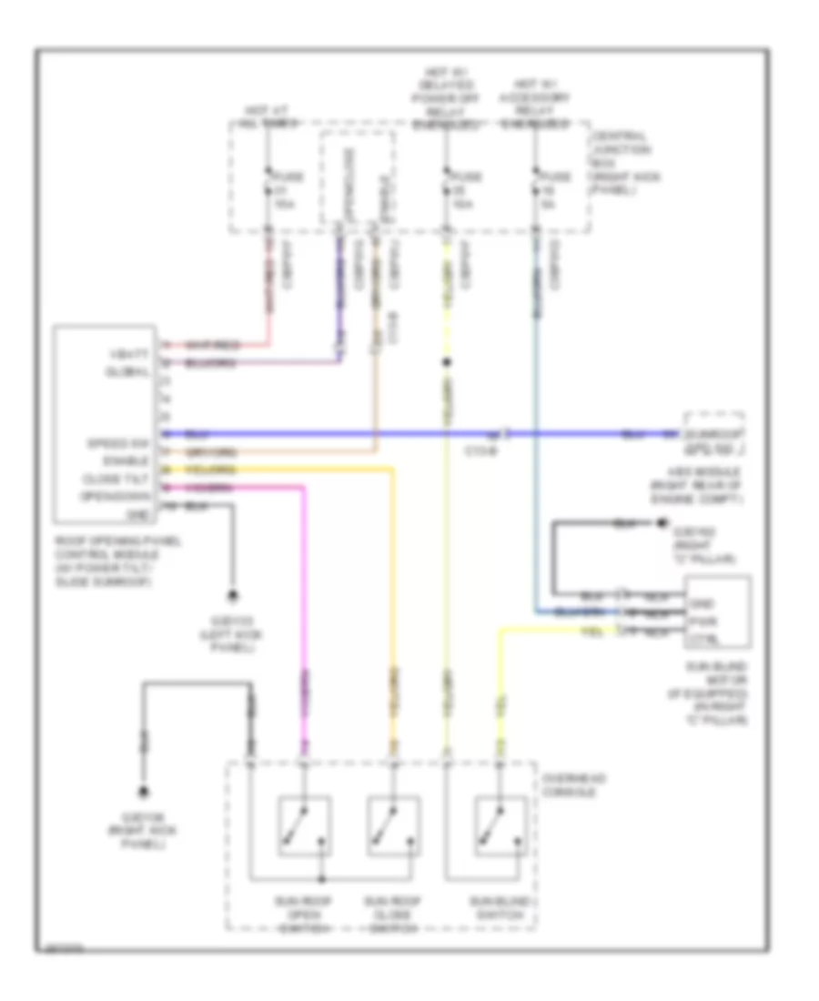 https://portal-diagnostov.com/license.html
Automotive Electricians Portal FZCO
Automotive Electricians Portal FZCO
https://portal-diagnostov.com/license.html
https://portal-diagnostov.com/license.html
Automotive Electricians Portal FZCO
Automotive Electricians Portal FZCOList of elements for Power Top/Sunroof Wiring Diagram for Jaguar XF 2011:
- Abs module (right rear of engine compt)
- C13-b
- C3bp01d
- C3bp01f
- C3bp01g
- C3bp01j
- Central junction box (right kick panel)
- Close tilt
- Ctrl
- Enable
- Fuse 10a
- Fuse 15a
- Fuse 5a
- G3d133 (left kick panel)
- G3d138 (right kick panel)
- G3d162 (right "c" pillar)
- Global
- Gnd
- Hot at all times
- Hot w/ accessory relay energized
- Hot w/ delayed power off relay energized
- Nca
- Open-down
- Open/close
- Overhead console
- Pwr
- Roof opening panel control module (w/ power tilt/ slide sunroof)
- Spd sig
- Speed sw
- Sun blind motor (if equipped) (in right "c" pillar)
- Sun blind switch
- Sun roof close switch
- Sun roof open switch
- Sunroof
- Vbatt
POWER WINDOWS
Power Windows Wiring Diagram (1 of 2) for Jaguar XF 2011
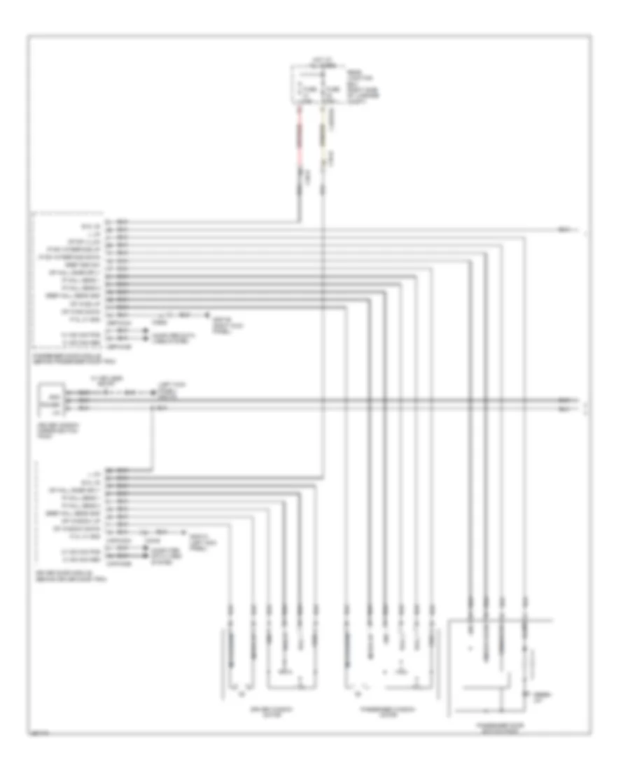 https://portal-diagnostov.com/license.html
Automotive Electricians Portal FZCO
Automotive Electricians Portal FZCO
https://portal-diagnostov.com/license.html
https://portal-diagnostov.com/license.html
Automotive Electricians Portal FZCO
Automotive Electricians Portal FZCOList of elements for Power Windows Wiring Diagram (1 of 2) for Jaguar XF 2011:
- (left kick panel) g3d133
- B kl 30
- C+ ms can pos
- C3a-b
- C3b-b
- C4bp01d
- Capw02a
- Capw02b
- Cbpw04a
- Cbpw04b
- Computer data lines system
- Driver door module (behind driver door trim)
- Driver window mirror switch pack
- Driver window motor
- Fuse 25a
- G3d133 (left kick panel)
- G3d138 (right kick panel)
- Gnd
- Green ld1
- Gref gnd sw
- Gref hall sens gnd
- Hall 1
- Hall 2
- Hot at all times
- Illum
- Ip hall sens 1
- Ip hall sens 2
- Ip sw interface down
- Ip sw interface up
- L lin
- Lin
- Motor down
- Motor up
- Op hall snsr sply
- Op sw illum
- Op wind down
- Op wind up
- Op window down
- Op window up
- P kl 31 gnd
- Passenger door module (behind passenger door trim)
- Passenger door switch pack
- Passenger window motor
- Power
- Rear junction box (right side of luggage compt)
- Vref
- W/ keyless entry
- Window down
- Window up
Power Windows Wiring Diagram (2 of 2) for Jaguar XF 2011
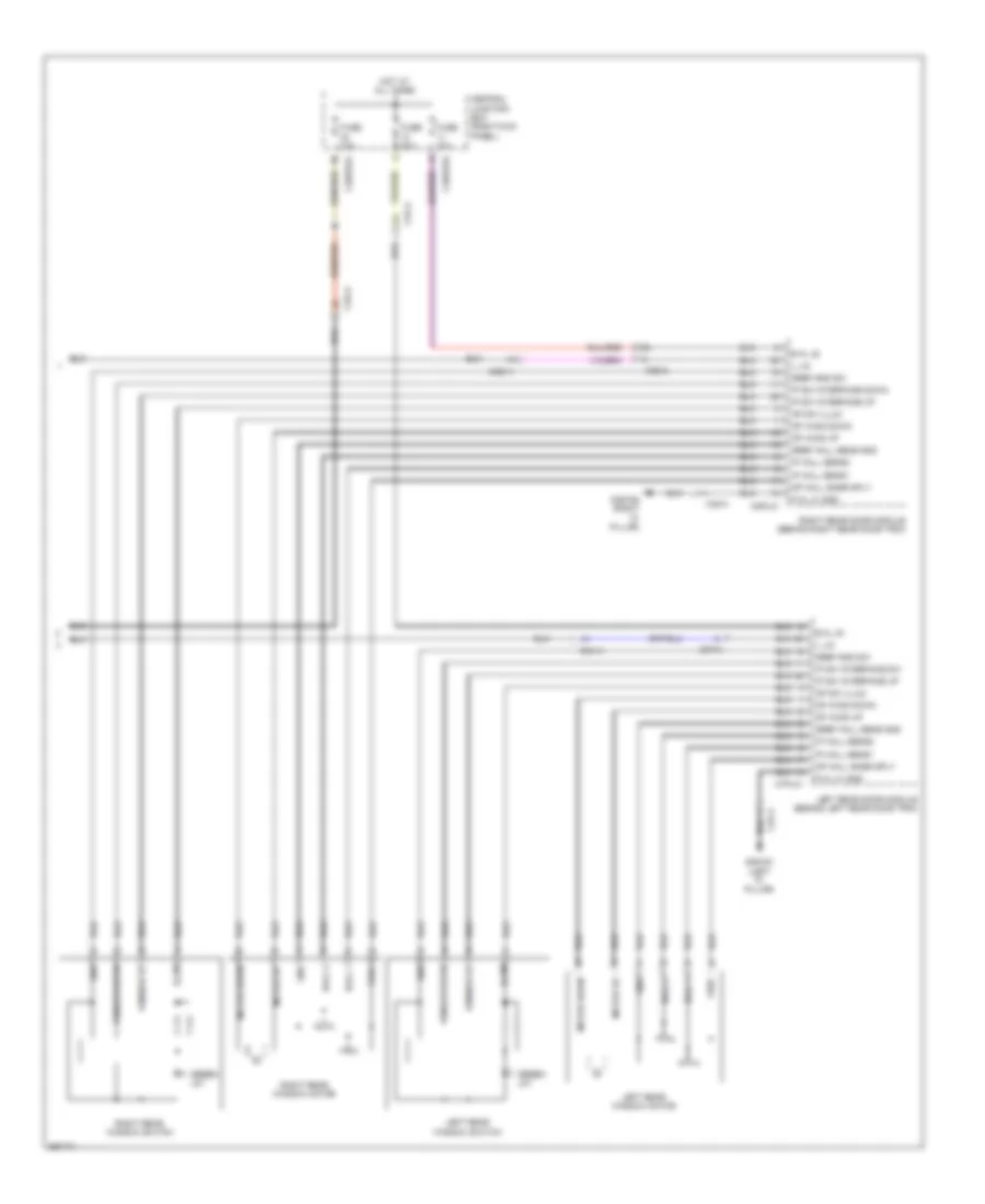 https://portal-diagnostov.com/license.html
Automotive Electricians Portal FZCO
Automotive Electricians Portal FZCO
https://portal-diagnostov.com/license.html
https://portal-diagnostov.com/license.html
Automotive Electricians Portal FZCO
Automotive Electricians Portal FZCOList of elements for Power Windows Wiring Diagram (2 of 2) for Jaguar XF 2011:
- B kl 30
- C37-a
- C38-a
- C3a-a
- C3b-a
- C3bp01b
- C3bp01g
- C7pl01
- C8pl01
- Central junction box (right kick panel)
- Fuse 10a
- Fuse 20a
- G3d161 (left "c" pillar)
- G3d162 (right "c" pillar)
- Gnd
- Green ld1
- Gref gnd sw
- Gref hall sens gnd
- Hall 1
- Hall 2
- Hot at all times
- Illum
- Ip hall sens1
- Ip hall sens2
- Ip sw interface down
- Ip sw interface dw
- Ip sw interface up
- L lin
- Left rear door module (behind left rear door trim)
- Left rear window motor
- Left rear window switch
- Motor down
- Motor up
- Op hall snsr sply
- Op sw illum
- Op wind down
- Op wind up
- P kl 31 gnd
- Right rear door module (behind right rear door trim)
- Right rear window motor
- Right rear window switch
- Vref
- Window down
- Window up
RADIO
Base Radio Wiring Diagram for Jaguar XF 2011
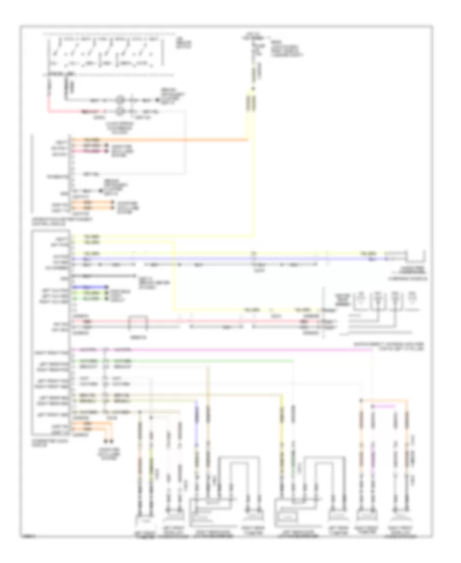 https://portal-diagnostov.com/license.html
Automotive Electricians Portal FZCO
Automotive Electricians Portal FZCO
https://portal-diagnostov.com/license.html
https://portal-diagnostov.com/license.html
Automotive Electricians Portal FZCO
Automotive Electricians Portal FZCOList of elements for Base Radio Wiring Diagram for Jaguar XF 2011:
- (behind instrument cluster) g2d115
- (behind instrument cluster) g2d116
- Am/fm diversity antenna amplifier (top of left "c" pillar)
- Ant pwr
- Ant scn
- Ant sig
- C23-a
- C23-e
- C23-r
- C2me03a
- C2me03b
- C2me03c
- C2me03d
- C2mt01a
- C2mt01b
- C2r115a
- C37-a
- C38-a
- C3a-b
- C3b-b
- C44-g
- C4bp01d
- C4me22b
- C9me35a
- C9me35b
- Clock spring (in steering column)
- Computer data lines system
- Ferrite
- Fm1
- Fm2
- Fm3
- Fr remote
- Fuse 15a
- G2d114 (behind center of dash)
- Gnd
- Hands free microphone
- Heated rear screen
- Hot at all times
- Ice remote switch
- Ice sig
- Information & entertainment control module
- Integrated audio module
- Left aux pos
- Left front door low range speaker
- Left front pos
- Left front tweeter
- Left rear
- Left rear door low range speaker
- Left rear pos
- Media
- Mem +
- Mem -
- Mic pos
- Mic screen
- Most rx
- Most tx
- Ms can +
- Ms can -
- Mute
- Nca
- Overhead console
- Portable audio circuit
- Pwr
- Rear junction box (right side of luggage compt)
- Red
- Right front door low range speaker
- Right front pos
- Right front tweeter
- Right rear
- Right rear door low range speaker
- Right rear pos
- Sa004
- Scn
- Sig
- Sw002
- Tweeter
- Vbatt
- Vol +
- Vol -
Portable Audio Wiring Diagram for Jaguar XF 2011
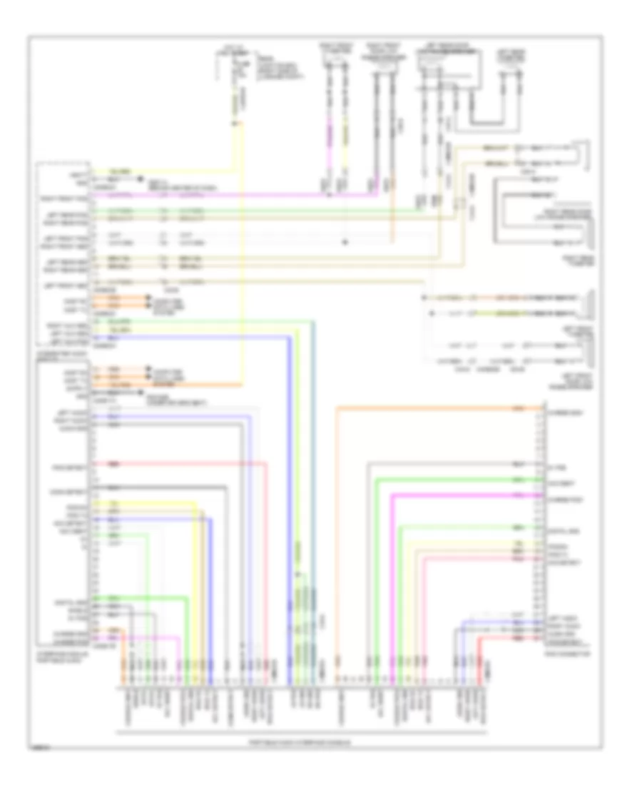 https://portal-diagnostov.com/license.html
Automotive Electricians Portal FZCO
Automotive Electricians Portal FZCO
https://portal-diagnostov.com/license.html
https://portal-diagnostov.com/license.html
Automotive Electricians Portal FZCO
Automotive Electricians Portal FZCOList of elements for Portable Audio Wiring Diagram for Jaguar XF 2011:
- 5v pos
- Acc detect
- Acc ident
- Audio gnd
- C23-a
- C23-e
- C2me03a
- C2me03b
- C2me03c
- C37-a
- C38-a
- C3a-b
- C3b-b
- C3me17a
- C3me17b
- C3me37a
- C3me37b
- C3me37c
- C44-g
- C4bp01d
- C4me22b
- Charge gnd
- Charge gnd1
- Charge pos
- Charge pos1
- Computer data lines system
- Conn detect
- Data+
- Data-
- Digital gnd
- Fuse 15a
- G2d114 (behind center of dash)
- G3d182b (under driver's seat)
- Gnd
- Hot at all times
- Integrated audio module
- Interface module portable audio
- Ipod connector
- Ipod detect
- Ipod rx
- Ipod tx
- Left audio
- Left aux pos
- Left front door low range speaker
- Left front pos
- Left front tweeter
- Left rear door low range speaker
- Left rear pos
- Left rear tweeter
- Lh gnd
- Lh pos
- Most rx
- Most tx
- Nca
- Pnk
- Portable audio interface console
- Rear junction box (right side of luggage compt)
- Red
- Rh gnd
- Rh pos
- Right audio
- Right front door low range speaker
- Right front pos
- Right front tweeter
- Right rear door low range speaker
- Right rear pos
- Right rear tweeter
- Shield
- Vbatt
Premium Radio Wiring Diagram for Jaguar XF 2011
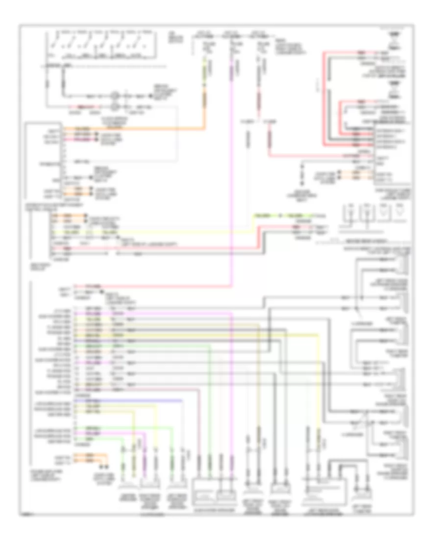 https://portal-diagnostov.com/license.html
Automotive Electricians Portal FZCO
Automotive Electricians Portal FZCO
https://portal-diagnostov.com/license.html
https://portal-diagnostov.com/license.html
Automotive Electricians Portal FZCO
Automotive Electricians Portal FZCOList of elements for Premium Radio Wiring Diagram for Jaguar XF 2011:
- (14 speaker)
- (behind instrument cluster) g2d115
- (behind instrument cluster) g2d116
- 14 speaker
- Am/fm diversity antenna amplifier (top of left "c" pillar)
- Amp
- Antenna 1
- Antenna 2
- Antenna scn 1
- Antenna scn 2
- C23-e
- C2mt01a
- C2mt01b
- C2r115a
- C37-a
- C3a-b
- C3b-a
- C3b-b
- C43-a
- C44-v
- C4bp01b
- C4bp01d
- C4bp01h
- C4me18a
- C4me18b
- C4me22a
- C4me22b
- C4me22d
- C4me24
- C4me41a
- C9me35b
- C9me35c
- C9me35e
- C9mn03c
- Center pos
- Center speaker
- Clock spring (in steering column)
- Computer data lines system
- Dab
- Dab antenna (center rear of roof)
- Dab module tuner (left side of luggage compt)
- Dab scn
- Dab sig
- Fl bass pos
- Fm1
- Fm2
- Fm3
- Fr bass pos
- Fr hi pos
- Fr remote
- Fuse 10a
- Fuse 15a
- Fuse 30a
- G3d182b (under driver's seat)
- G4d172 (left side of luggage compt)
- Gnd
- Gnd 1
- Heated rear window
- Hot at all times
- Iboc radio module
- Ice remote switch
- Ice sig
- Information & entertainment control module
- Left front door low range speaker
- Left front door mid range speaker (14 speaker)
- Left front tweeter
- Left rear
- Left rear door low range speaker
- Left rear surround sound speaker
- Lf hi pos
- Lhr surround pos
- Media
- Mem +
- Mem -
- Most rx
- Most tx
- Ms can +
- Ms can -
- Mute
- Nca
- Power amplifier (left side of luggage compt)
- Pwr
- Rear junction box (right side of luggage compt)
- Red
- Rhr surround pos
- Right front door low range speaker
- Right front door mid range speaker (14 speaker)
- Right front tweeter
- Right rear door low range speaker
- Right rear surround sound speaker
- Right rear tweeter
- Rl pos
- Rr pos
- Sa004
- Scn
- Sig
- Sub woofer a pos
- Sub woofer b pos
- Subwoofer speaker
- Sw002
- Tweeter
- Vbatt
- Vol +
- Vol -
- W/ dab
- W/ iboc
Satellite Radio Wiring Diagram for Jaguar XF 2011
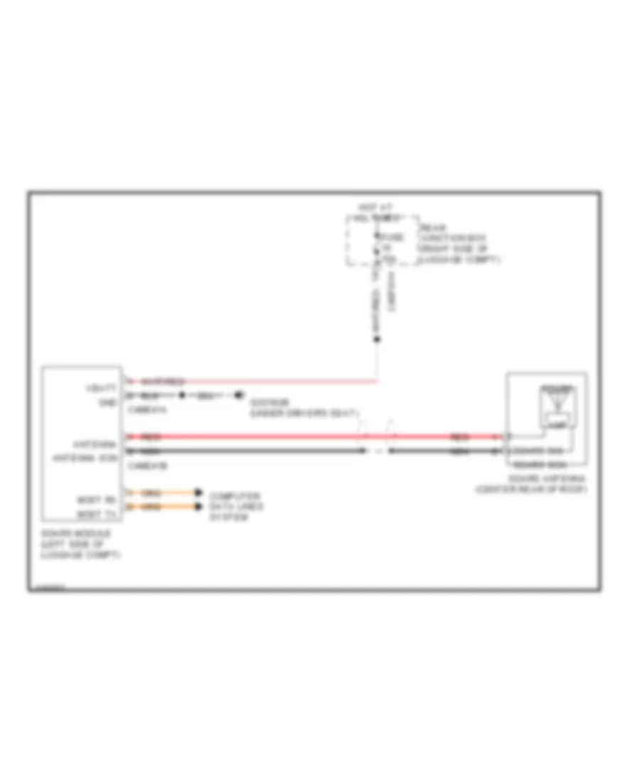 https://portal-diagnostov.com/license.html
Automotive Electricians Portal FZCO
Automotive Electricians Portal FZCO
https://portal-diagnostov.com/license.html
https://portal-diagnostov.com/license.html
Automotive Electricians Portal FZCO
Automotive Electricians Portal FZCOList of elements for Satellite Radio Wiring Diagram for Jaguar XF 2011:
- Amp
- Antenna
- Antenna scn
- C4bp01h
- C4me41a
- C4me41b
- Computer data lines system
- Fuse 10a
- G3d182b (under driver's seat)
- Gnd
- Hot at all times
- Most rx
- Most tx
- Nca
- Rear junction box (right side of luggage compt)
- Red
- Sdars
- Sdars antenna (center rear of roof)
- Sdars module (left side of luggage compt)
- Sdars scn
- Sdars sig
- Vbatt
SHIFT INTERLOCK
Shift Interlock Wiring Diagram for Jaguar XF 2011
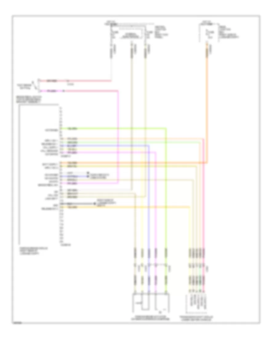 https://portal-diagnostov.com/license.html
Automotive Electricians Portal FZCO
Automotive Electricians Portal FZCO
https://portal-diagnostov.com/license.html
https://portal-diagnostov.com/license.html
Automotive Electricians Portal FZCO
Automotive Electricians Portal FZCOList of elements for Shift Interlock Wiring Diagram for Jaguar XF 2011:
- (right side of luggage compt) g4d173
- Brake pedal sw
- Brake pedal switch (top of brake pedal bracket assembly)
- C13-d
- C33-c
- C3bp01e
- C3bp01f
- C44-p
- C44-r
- C4bp01c
- C4cb01a
- C4cb01b
- Central junction box (right kick panel)
- Computer data lines system
- Epb rel 1
- Epb rel 2
- Epb rtn
- Foot brake switch
- Fuse 30a
- Fuse 5a
- Gnd
- Hall sens gnd
- Hall sig
- Hot at all times
- Hs can pos
- Ign
- Internal electronics
- Logic batt
- Motor pos
- Parking brake actuator (on rear suspension subframe)
- Parking brake module (right rear of luggage compt)
- Rear junction box (right side of luggage compt)
- Release sw 1
- Release sw 2
- Sw rtn
- Transmission shift module (under center console)
STARTING/CHARGING
Charging Wiring Diagram for Jaguar XF 2011
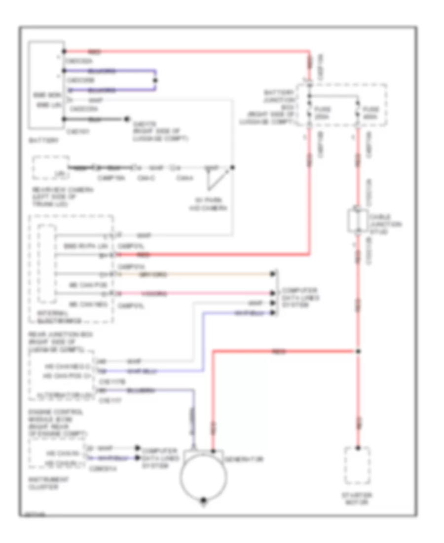 https://portal-diagnostov.com/license.html
Automotive Electricians Portal FZCO
Automotive Electricians Portal FZCO
https://portal-diagnostov.com/license.html
https://portal-diagnostov.com/license.html
Automotive Electricians Portal FZCO
Automotive Electricians Portal FZCOList of elements for Charging Wiring Diagram for Jaguar XF 2011:
- + c4dc02a
- + c4dc05b
- Aid camera
- Alternator lin
- Battery
- Battery junction box (right side of luggage compt)
- Bms lin
- Bms mon
- Bms rvpa lin
- C1dc12a
- C1dc12b
- C1e117
- C1e117b
- C2mc01a
- C44-a
- C44-c
- C4bf10a
- C4bf10b
- C4bp01a
- C4bp01l
- C4d101
- C4dco5a
- C4df10a
- C4mp19a
- Cable junction stud
- Computer data lines system
- Engine control module (ecm) (right rear of engine compt)
- Fuse 250a
- Fuse 400a
- G4d178 (right side of luggage compt)
- Generator
- Hs can in +
- Hs can in -
- Hs can pos c+
- Instrument cluster
- Internal electronics
- Lin
- Ms can pos
- Nca
- Rear junction box (right side of luggage compt)
- Rearview camera (left side of trunk lid)
- Red
- Starter motor
- W/ park
Starting Wiring Diagram for Jaguar XF 2011
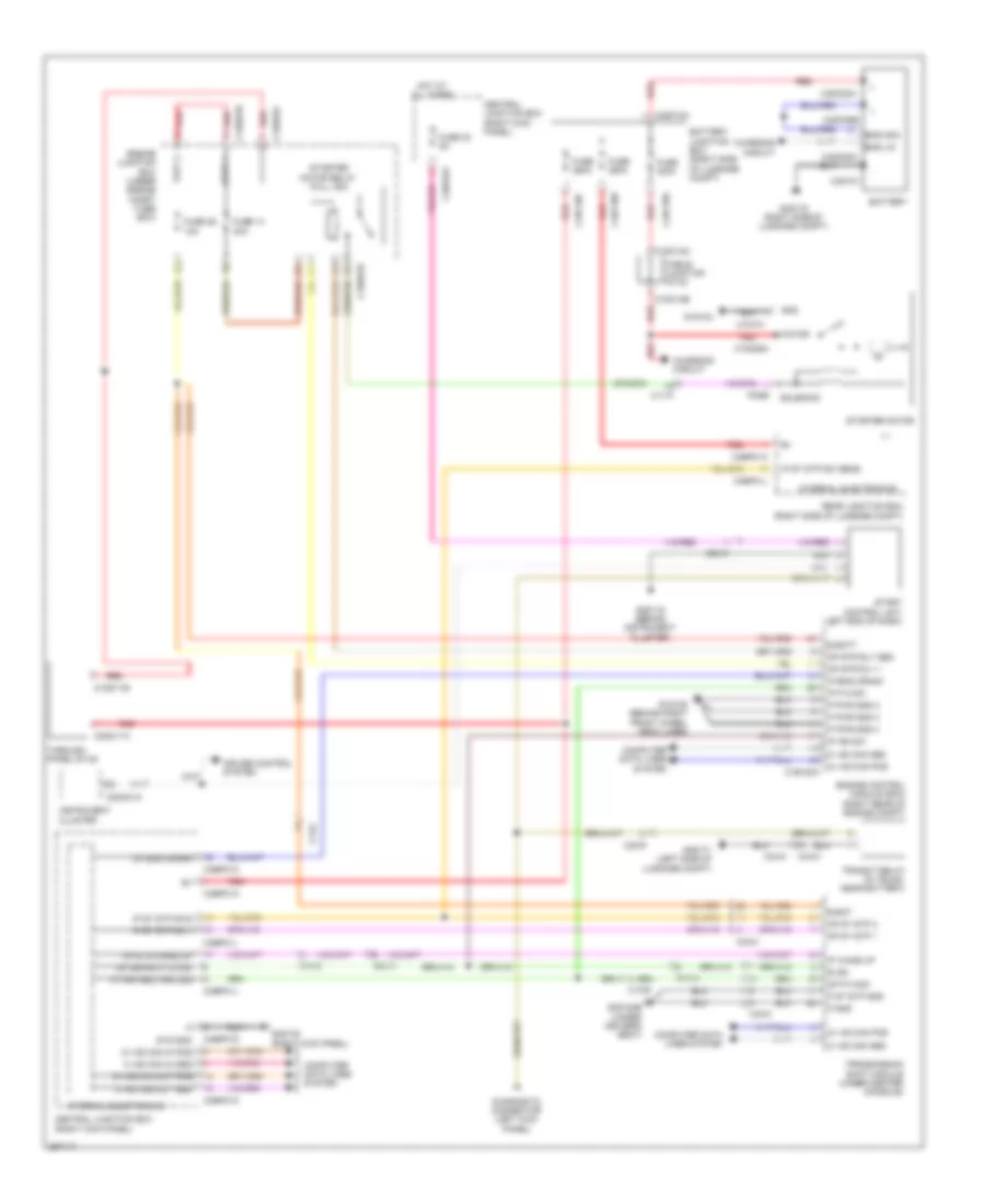 https://portal-diagnostov.com/license.html
Automotive Electricians Portal FZCO
Automotive Electricians Portal FZCO
https://portal-diagnostov.com/license.html
https://portal-diagnostov.com/license.html
Automotive Electricians Portal FZCO
Automotive Electricians Portal FZCOList of elements for Starting Wiring Diagram for Jaguar XF 2011:
- B bat
- B batt
- B ign
- Battery
- Battery junction box (right side of luggage compt)
- Bms lin
- Bms mon
- C+ hs can pos
- C+ ms can in pos
- C+ ms can out pos
- C11-p
- C13-c
- C13-e
- C1bb01b
- C1bb01c
- C1d101
- C1dc11b
- C1dc12a
- C1dc12b
- C1dc35a
- C1e120a
- C23-d
- C23-r
- C2mc01a
- C33-c
- C3bp01a
- C3bp01d
- C3bp01f
- C3bp01h
- C3bp01j
- C3bp01k
- C3bp01l
- C3dc11a
- C44-m
- C44-n
- C4bf10a
- C4bf10b
- C4bf10c
- C4bp01a
- C4bp01l
- C4d101
- C4dc02a
- C4dc05a
- C4dc05b
- C4df10a
- Cable junction stud
- Central junction box (right kick panel)
- Charging circuit
- Computer data lines system
- Cruise control system
- Diagnostic connector (left kick panel)
- Engine control module (ecm) (right rear of engine compt)
- Engine junction box (under engine compt fuse box)
- Fuse 14 30a
- Fuse 250a
- Fuse 26 10a
- Fuse 32 5a
- Fuse 400a
- G1d108 (behind right front wheel arch liner)
- G1d124
- G2d115 (behind instrument cluster)
- G3d138 (right kick panel)
- G3d182b (under driver's seat)
- G4d171 (left side of luggage compt)
- G4d178 (right side of luggage compt)
- Gnd
- Hot at all times
- Instrument cluster
- Internal electronics
- Ip eng crank
- Ip ign sw
- Ip p n sw
- Ip prk neutral sig
- Ip st stp sw sens
- Ip st stp sw1
- Ip st stp sw2
- Ip wake up
- Motor
- Op eng crank
- Op ets wake up
- Op ign sply 2 fwd
- Op p n sig
- Op st stp 1
- Op st stp 2
- Op str rly +
- P gnd
- P pwr gnd 2
- P pwr gnd 3
- P pwr gnd 4
- P st stp gnd
- Pi099
- Rear junction box (right side of luggage compt)
- Red
- Solenoid
- Start control unit (left end of dash)
- Starter motor
- Starter motor relay (full iso)
- Sys gnd
- Tap1 1
- Tap1 2
- Through panel stud
- Transit relay (in trunk, near battery)
- Transmission shift module (under center console)
SUPPLEMENTAL RESTRAINTS
Supplemental Restraints Wiring Diagram (1 of 2) for Jaguar XF 2011
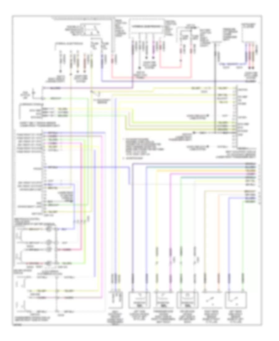 https://portal-diagnostov.com/license.html
Automotive Electricians Portal FZCO
Automotive Electricians Portal FZCO
https://portal-diagnostov.com/license.html
https://portal-diagnostov.com/license.html
Automotive Electricians Portal FZCO
Automotive Electricians Portal FZCOList of elements for Supplemental Restraints Wiring Diagram (1 of 2) for Jaguar XF 2011:
- (under rear of center console) c3d174
- Air bag deact lamp
- Air bag deployed
- Battery junction box (right side of luggage compt)
- Bts
- Bts gnd
- Bts vref
- C23-a
- C23-b
- C23-c
- C2mc01a
- C2r103a
- C2r103b
- C2r115a
- C33-f
- C33-g
- C33-j
- C3bp01a
- C3bp01d
- C3bp01e
- C3bp01k
- C3r114a
- C4bf10b
- C4bf10c
- C4bp01a
- C4bp01d
- C4bp01f
- C4bp01k
- C4bp01l
- Central junction box (right kick panel)
- Clock spring (in steering column)
- Computer data lines system
- Driver air bag module
- Driver side air bag (left side of driver's seat back)
- Drv front st1 pwr
- Drv front st1 rtn
- Drv front st2 pwr
- Drv front st2 rtn
- Fuse 10a
- Fuse 250a
- G3d138 (right kick panel)
- G3d183a (under front passenger's seat)
- G4d173 (right side of luggage compt)
- Gnd
- Hot at all times
- Hs can +
- Hs can -
- Ignition
- Instrument cluster
- Internal electronics
- Left rear side impact sensor (base of left "c" pillar)
- Left side curtain air bag (top of left "b" pillar)
- Nca bts
- Nca bts gnd
- Nca bts vref
- Overhead console
- Pacos
- Pad status led
- Pass front st1 pwr
- Pass front st1 rtn
- Pass front st2 pwr
- Pass front st2 rtn
- Passenger side air bag (right side of front passenger's seat back)
- Passenger's air bag module (behind right side of dash)
- Pcb relay restraints ignition relay
- Pin shorting bars engaged when module connector is disconnected from harness (shorting bars are connected between pins: 1-2, 3-4, 5-6 & 15-16: conn. c3r114a
- Pressure mat sensor (under passenger seat)
- Ps gnd
- Ps vref
- Rear junction box (right side of luggage comp)
- Red
- Restraints control module (rcm) (under rear of center console)
- Right rear side impact sensor (base of right "c" pillar)
- Sa001
- Sa002
- Sa003
- Safety belt tension sensor (under front passenger's seat)
- Seat occupancy module (w/ occupancy sensing) (under front passenger's seat)
- Seat occupancy sensor (under front passenger's seat)
- Shorting bar
- W/ occupancy sensing
Supplemental Restraints Wiring Diagram (2 of 2) for Jaguar XF 2011
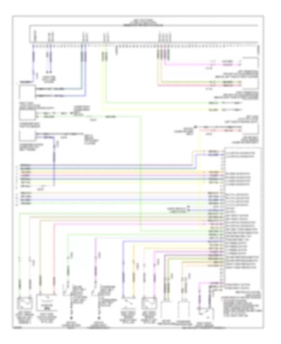 https://portal-diagnostov.com/license.html
Automotive Electricians Portal FZCO
Automotive Electricians Portal FZCO
https://portal-diagnostov.com/license.html
https://portal-diagnostov.com/license.html
Automotive Electricians Portal FZCO
Automotive Electricians Portal FZCOList of elements for Supplemental Restraints Wiring Diagram (2 of 2) for Jaguar XF 2011:
- (left kick panel) (w/ deployable hood) pedestrian protection module
- (under front passenger's seat) g3d183a
- C11-e
- C13-a
- C13-b
- C13-d
- C23-r
- C2rp03a
- C2rp03b
- C33-d
- C33-f
- C33-g
- C33-j
- C3a-b
- C3b-b
- C3r114b
- Computer data lines system
- Driver pretensioner
- Driver pretensioner pwr
- Driver pretensioner rtn
- Driver seat belt buckle switch (in driver's seat belt buckle)
- Driver seat track sensor (under driver's seat)
- Driver seatbelt sw
- Drv front cs pwr
- Drv front cs rtn
- Drv seat posn sens pwr
- Front pass preten pwr
- Front pass preten rtn
- G2d115 (behind instrument cluster)
- G3d182a (under driver's seat)
- G3d183a (under front passenger's seat)
- Hs can +
- Hs can -
- Left front impact sensor (behind left headlight assembly)
- Left front side impact sensor (base of left "b" pillar)
- Left hood latch actuator (left side of engine compt)
- Left pedestrian protection accelerometer (behind left side of front bumper)
- Lh acc +
- Lh acc -
- Lh act +
- Lh act -
- Lh c pillar cs pwr
- Lh c pillar cs rtn
- Lh curtain air bag pwr
- Lh curtain air bag rtn
- Lh press cs pwr
- Lh press cs rtn
- Lh side air bag pwr
- Lh side air bag rtn
- Nca
- Pass front cs pwr
- Pass front cs rtn
- Pass seatbelt sw
- Pass seatposn sens pwr
- Passenger air bag disable switch (belt minder)
- Passenger pretensioner
- Passenger seat belt buckle switch (in passenger's seat belt buckle)
- Passenger seat position sensor
- Pin shorting bars engaged when module connector is disconnected from harness (shorting bars are connected between pins: 1-2, 7-8, 9-10 & 21-22: conn. c3r114b
- Restraints control module (rcm) (under rear of center console)
- Rh acc +
- Rh acc -
- Rh act +
- Rh act -
- Rh c pillar cs pwr
- Rh c pillar cs rtn
- Rh curtain air bag pwr
- Rh curtain air bag rtn
- Rh press cs pwr
- Rh press cs rtn
- Rh side air bag pwr
- Rh side air bag rtn
- Right front impact sensor (behind right headlight assembly)
- Right front side impact sensor (base of right "b" pillar)
- Right hood latch actuator (right side of engine compt)
- Right pedestrian protection accelerometer (behind right side of front bumper)
- Right side curtain air bag (top of right "b" pillar)
- Run/strt
- Shorting bar
TRANSMISSION
A/T Wiring Diagram for Jaguar XF 2011
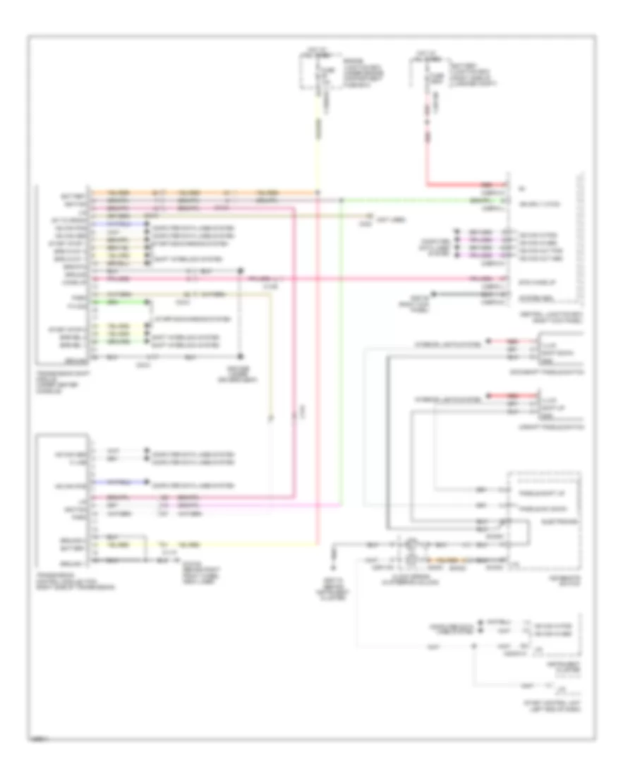 https://portal-diagnostov.com/license.html
Automotive Electricians Portal FZCO
Automotive Electricians Portal FZCO
https://portal-diagnostov.com/license.html
https://portal-diagnostov.com/license.html
Automotive Electricians Portal FZCO
Automotive Electricians Portal FZCOList of elements for A/T Wiring Diagram for Jaguar XF 2011:
- (not used)
- Battery
- Battery junction box (right side of luggage compt)
- C11-p
- C13-c
- C13-e
- C1bb01b
- C2mc01a
- C2r115a
- C33-c
- C33c
- C3bpo1a
- C3bpo1d
- C3bpo1j
- C3bpo1k
- C4bf10c
- Central junction box (right kick panel)
- Clock spring (in steering column)
- Computer data lines system
- Downshift paddle switch
- Electronics
- Engine junction box (under engine compartment fuse box)
- Epb rel 1
- Epb rel 2
- Epb rtn
- Ets wake up
- Fuse 10a
- Fuse 250a
- G1d108 (behind right front wheel arch liner)
- G2d115 (behind instrument cluster)
- G3d138 (right kick panel)
- G3d182b (under driver's seat)
- Gnd
- Ground
- Ground 1
- Ground 2
- Hot at all times
- Hs can in pos
- Hs can pos
- Ice remote switch
- Ign sply 2 fwd
- Ignition
- Illum
- Instrument cluster
- Interior lights system
- K line
- Lin
- Ms can in pos
- Ms can out pos
- Ok to crank
- P n sig
- Paddle shift up
- Paddle sw down
- Park
- Red
- Sa004
- Shift down
- Shift interlock system
- Shift up
- Start control unit (left end of dash)
- Start stop 1
- Start stop 2
- Starting/charging system
- Sw002
- Sw003
- Sw005
- System gnd
- Transmission control module (tcm) (right side of transmission)
- Transmission shift module (under center console)
- Upshift paddle switch
- Wake up
Rear Differential Lock Wiring Diagram for Jaguar XF 2011
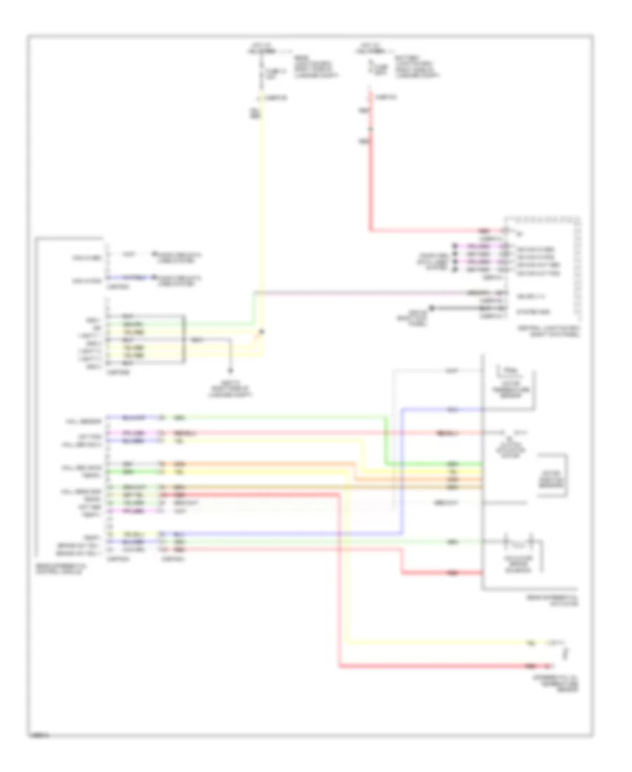 https://portal-diagnostov.com/license.html
Automotive Electricians Portal FZCO
Automotive Electricians Portal FZCO
https://portal-diagnostov.com/license.html
https://portal-diagnostov.com/license.html
Automotive Electricians Portal FZCO
Automotive Electricians Portal FZCOList of elements for Rear Differential Lock Wiring Diagram for Jaguar XF 2011:
- Actuator brake solenoid
- Battery junction box (right side of luggage compt)
- Brake act sol +
- Brake act sol -
- C3bp01a
- C3bp01d
- C3bp01e
- C4bf10c
- C4bp01b
- C4et63a
- C4et63b
- C4et63c
- C4et64a
- Can in pos
- Cbp01k
- Central junction box (right kick panel)
- Clutch actuation motor
- Computer data lines system
- Differential oil temperature sensor
- Fuse 10 40a
- Fuse 250a
- G3d138 (right kick panel)
- G4d173 (right side of luggage compt)
- Gnd 1
- Gnd 2
- Gnd 3
- Hall sen sig a
- Hall sen sig b
- Hall sens gnd
- Hall sensor
- Hot at all times
- Ign
- Ign sply 2
- Mot pos
- Motor position sensors
- Motor temperature sensor
- Ms can in pos
- Ms can out pos
- Rear differential actuator
- Rear differential control module
- Rear junction box (right side of luggage compt)
- Red
- System gnd
- Temp1+
- Temp1-
- Temp2+
- Temp2-
- V batt 1
- V batt 2
- V batt 3
TRUNK, TAILGATE, FUEL DOOR
Trunk & Fuel Door Release Wiring Diagram for Jaguar XF 2011
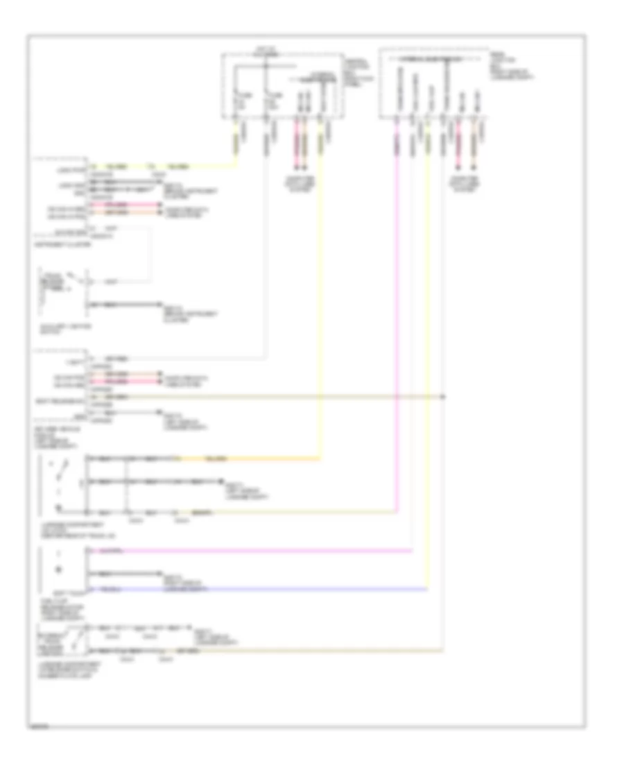 https://portal-diagnostov.com/license.html
Automotive Electricians Portal FZCO
Automotive Electricians Portal FZCO
https://portal-diagnostov.com/license.html
https://portal-diagnostov.com/license.html
Automotive Electricians Portal FZCO
Automotive Electricians Portal FZCOList of elements for Trunk & Fuel Door Release Wiring Diagram for Jaguar XF 2011:
- Aux sw sig
- Auxiliary lighting switch
- Boot open
- Boot release sw
- C23-d
- C2mc01a
- C2mc01b
- C3bp01b
- C3bp01f
- C3bp01k
- C44-a
- C44-c
- C4bp01f
- C4bp01k
- C4bp01l
- C4pk28c
- C4pk28d
- C4pk28e
- Central junction box (right kick panel)
- Computer data lines system
- External trunk release switch
- Fuel flap
- Fuel flap mtr
- Fuel flap release motor (right side of luggage compt)
- Fuse 20a
- Fuse 5a
- G2d115 (behind instrument cluster)
- G4d171 (left side of luggage compt)
- G4d172 (left side of luggage compt)
- G4d173 (right side of luggage compt)
- Gnd
- Hot at all times
- Instrument cluster
- Internal electronics
- Keyless vehicle module (left side of luggage compt)
- Logic gnd
- Logic pwr
- Luggage compartment lid latch (center rear of trunk lid)
- Luggage compartment lid release switch & number plate lamp
- Ms can +
- Ms can -
- Ms can in pos
- Ms can pos
- Rear junction box (right side of luggage compt)
- Soft touch
- Trunk mtr open
- Trunk release sw
- Trunk release switch
- V batt
WARNING SYSTEMS
Key Reminder & Seat Belt Warning Wiring Diagram for Jaguar XF 2011
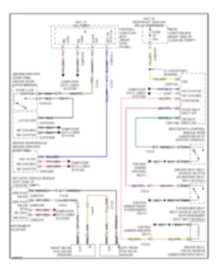 https://portal-diagnostov.com/license.html
Automotive Electricians Portal FZCO
Automotive Electricians Portal FZCO
https://portal-diagnostov.com/license.html
https://portal-diagnostov.com/license.html
Automotive Electricians Portal FZCO
Automotive Electricians Portal FZCOList of elements for Key Reminder & Seat Belt Warning Wiring Diagram for Jaguar XF 2011:
- (behind driver's door trim) driver door latch module
- Ajar sw
- Brk pad wear
- Brk pad wear rtn
- C12-b
- C13-a
- C13-e
- C23-a
- C2mco1a
- C2mco1b
- C33-d
- C33-g
- C3a-a
- C3bp01j
- C3bp01k
- C3r114a
- C44-p
- C4bp01f
- C4pk28d
- Capl63
- Capw02a
- Capw02b
- Central junction box (right kick panel)
- Computer data lines system
- Door ajar switch
- Dr seat belt sw c3r114b
- Driver door module (behind driver's door trim)
- Driver seat belt buckle switch (in driver's seat belt buckle)
- Driver seat track sensor (under driver's seat)
- Fuse 10a
- G3d182a (under driver's seat)
- G3d183a (under front passenger's seat)
- Hot at all times
- Hot w/ restraint ignition relay energized
- Hs can pos
- Ign
- In left front pad wear sensor
- Instrument cluster
- Key in sw
- Keyless vehicle module (left side of luggage compt)
- Latch gnd
- Ms can pos
- Ms can+
- Ms can+ c2mco1a
- Ms can-
- Nca
- Out
- Pass seat belt sw
- Passenger seat belt buckle switch (in passenger's seat belt buckle)
- Pwr sens
- Rear junction box (right side of luggage compt)
- Restraints control module (rcm) (under rear of center console)
- Right rear pad wear sensor
- Status key in
- W/ occupancy sensing
Tire Pressure Monitoring Wiring Diagram for Jaguar XF 2011
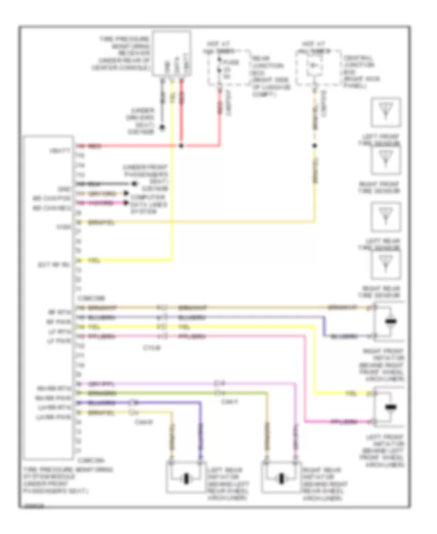 https://portal-diagnostov.com/license.html
Automotive Electricians Portal FZCO
Automotive Electricians Portal FZCO
https://portal-diagnostov.com/license.html
https://portal-diagnostov.com/license.html
Automotive Electricians Portal FZCO
Automotive Electricians Portal FZCOList of elements for Tire Pressure Monitoring Wiring Diagram for Jaguar XF 2011:
- (under driver's seat) g3d182b
- (under front passenger's seat) g3d183b
- C13-b
- C3bp01e
- C3mc39a
- C3mc39b
- C44-w
- C44-y
- C4bp01f
- Central junction box (right kick panel)
- Computer data lines system
- Data
- Ext rf rx
- Fuse 5a
- Gnd
- Hot at all times
- Left front initiator (behind left front wheel arch liner)
- Left front tire sensor
- Left rear initiator (behind left rear wheel arch liner)
- Left rear tire sensor
- Lf pwr
- Lf rtn
- Lh rr pwr
- Lh rr rtn
- Ms can pos
- Rear junction box (right side of luggage compt)
- Red
- Rf pwr
- Rf rtn
- Rh rr pwr
- Rh rr rtn
- Right front initiator (behind right front wheel arch liner)
- Right front tire sensor
- Right rear initiator (behind right rear wheel arch liner)
- Right rear tire sensor
- Tire pressure monitoring receiver (under rear of center console)
- Tire pressure monitoring system module (under front passenger's seat)
- Vbatt
- Vign
WIPER/WASHER
Wiper/Washer Wiring Diagram (1 of 2) for Jaguar XF 2011
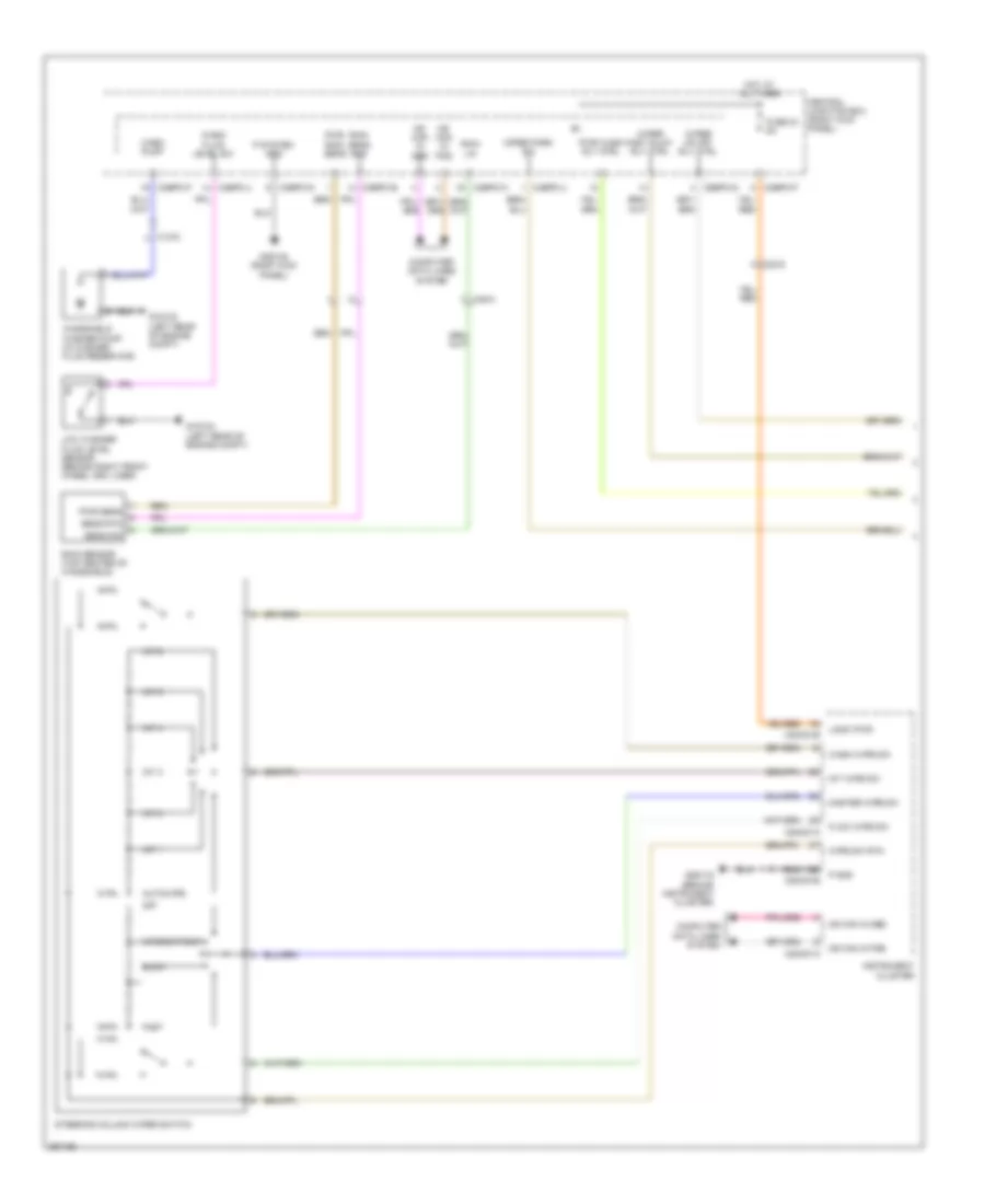 https://portal-diagnostov.com/license.html
Automotive Electricians Portal FZCO
Automotive Electricians Portal FZCO
https://portal-diagnostov.com/license.html
https://portal-diagnostov.com/license.html
Automotive Electricians Portal FZCO
Automotive Electricians Portal FZCOList of elements for Wiper/Washer Wiring Diagram (1 of 2) for Jaguar XF 2011:
- Autowipe
- C13-d
- C23-d
- C2mc01a
- C2mc01b
- C3bp01d
- C3bp01e
- C3bp01f
- C3bp01g
- C3bp01j
- C3bp01k
- C49-a
- Central junction box (right kick panel)
- Computer data lines system
- Fast
- Flick wipe sw
- Fuse 34 5a
- G1d123 (left rear of engine compt)
- G2d115 (behind instrument cluster)
- G3d138 (right kick panel)
- Hot at all times
- Instrument cluster
- Int 1
- Int 2
- Int 3
- Int 4
- Int 5
- Int 6
- Int wipe sw
- Intermittent
- Logic pwr
- Low washer fluid level sensor (behind right front wheel arc liner)
- Master wipe sw
- Ms can in pos
- Off
- P gnd
- P system gnd
- Pwr rain sens
- Pwr sens
- Pwr wash rly ctrl
- Rain lin
- Rain sens gnd
- Rain sensor (top center of windshield)
- Sens rtn
- Sens sig
- Slow
- Steering column wiper switch
- Wash fluid level sw
- Wash pump
- Wash wipe sw
- Windshield washer pump (in washer fluid reservoir)
- Wipe sw rtn
- Wiper fast slow rly ctrl
- Wiper on off rly ctrl
- Wiper park sw
Wiper/Washer Wiring Diagram (2 of 2) for Jaguar XF 2011
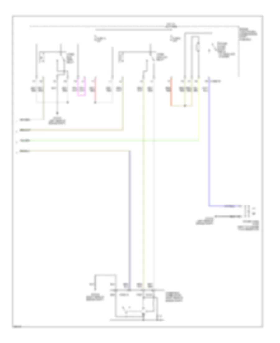 https://portal-diagnostov.com/license.html
Automotive Electricians Portal FZCO
Automotive Electricians Portal FZCO
https://portal-diagnostov.com/license.html
https://portal-diagnostov.com/license.html
Automotive Electricians Portal FZCO
Automotive Electricians Portal FZCOList of elements for Wiper/Washer Wiring Diagram (2 of 2) for Jaguar XF 2011:
- C1bb01b n5
- Engine junction box (under engine compt fuse box)
- Fast
- Fuse 13 30a
- Fuse 6 30a
- G1d120 (right rear of engine compt)
- G1d123 (left rear of engine compt)
- Gnd
- Hot at all times
- Park in
- Power wash pump (next to washer fluid reservoir)
- Power wash pump relay (w/ headlamp washer)
- Slow
- Windshield wiper motor (right rear of engine compt)
- Wiper high/low relay
- Wiper run/ park relay

 Čeština
 Dansk
Dansk Deutsch
 Ελληνικά
 English
 English
 Español
 Suomi
Suomi Français
 Français
 עברית
עברית Hrvatski
 Magyar
 Italiano
 한국어
한국어 Nederlands
 Polski
 Português
 Português
 Română
 Русский
 Slovenčina
 Slovenščina
 Svenska
 Türkçe
 中文 (中国)
