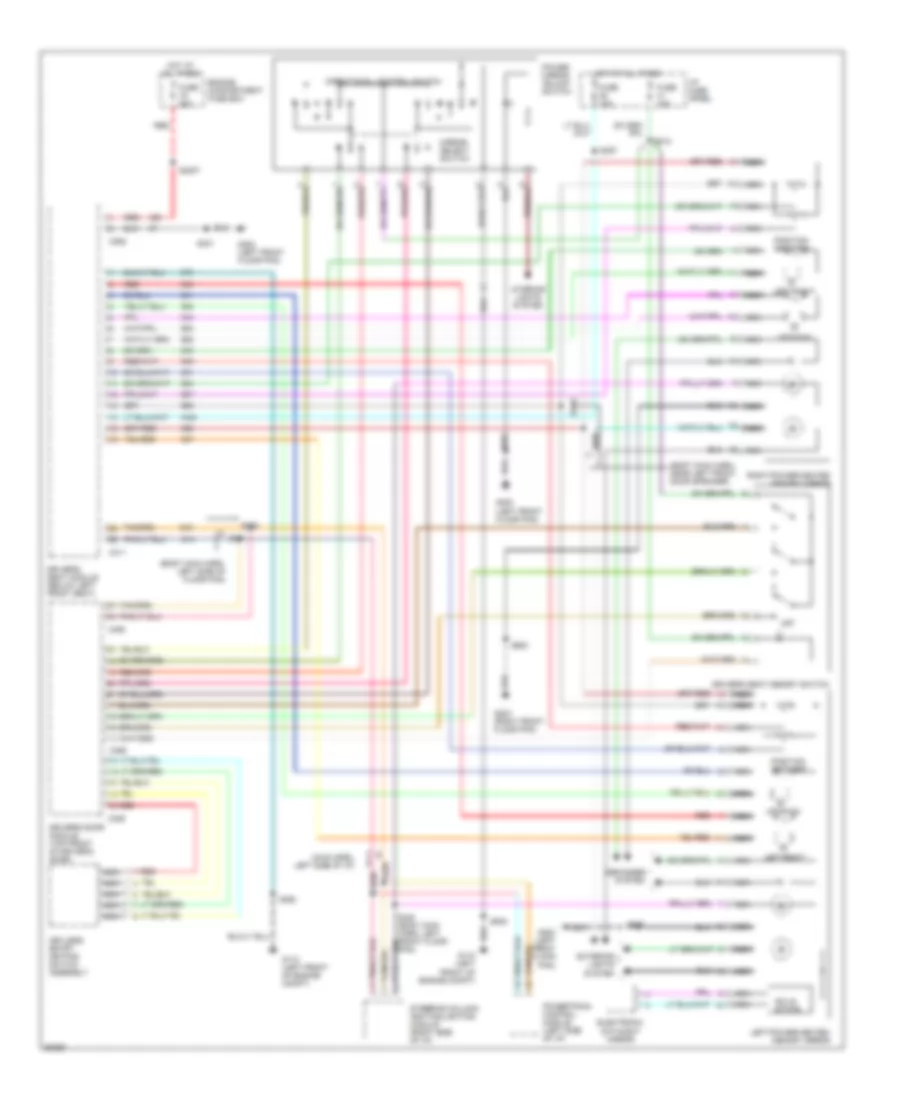
AIR CONDITIONING
Air Conditioning Wiring Diagrams for Lincoln Mark VIII 1997
 https://portal-diagnostov.com/license.html
Automotive Electricians Portal FZCO
Automotive Electricians Portal FZCO
https://portal-diagnostov.com/license.html
https://portal-diagnostov.com/license.html
Automotive Electricians Portal FZCO
Automotive Electricians Portal FZCO
List of elements for Air Conditioning Wiring Diagrams for Lincoln Mark VIII 1997:
- (dash panel to headlamp junction harn, left rear corner of eng compt)
- (dash panel to headlamp junction harn, on elect cooling fan breakout)
- (dash panel to headlamp junction harn, on vlcm breakout)
- (dash panel to headlamp junction harn, right front corner of eng compt)
- (engine cntrl sens harn, in pcm breakout)
- (engine cntrl sens harn, left rear corner of eng compt)
- (left front of engine compt)
- (lower front center of eng compartment)
- (main harn, near air bag diagnostic module breakout)
- (main harn, near right i/p lamp breakout)
- (main harn, near tilt relay conn breakout)
- (right front corner of engine compartment) g101
- (right front corner of engine compt)
- (right side of floor pan, front of right door)
- A/c clutch coil
- A/c cycling sw
- A/c cycling switch (right rear of engine compartment)
- A/c demand req
- A/c refrigerant pressure sensor (right front corner of engine compartment)
- Ambient sensor in
- Ambient temperature sensor (front center of engine compartment)
- Batt
- Battery
- Blend door actuator (behind right side of i/p, on center of
- Blower motor
- Blower motor relay (right side of i/p)
- Blower motor speed controller (behind right side of i/p,
- C272
- C273
- Cooling fan mtr
- Data
- Data (+)
- Data (-)
- Eatc sun load sensor (top right side of i/p)
- Electric cooling fan
- Electronic automatic temperature control (eatc) module (center of i/p)
- Engine compartment fuse box
- Engine controls system
- Evaporator assembly)
- Fuse 10a
- Fuse 15a
- Fuse 40a
- G100
- G101
- G200 (left side of floor pan, front of left door)
- G203
- Ground
- Hot at all times
- Hot in run
- I/p fuse panel
- Ignition
- Illumination
- In-car sensor input
- In-car temperature sensor (behind center of i/p, near eatc module)
- Interior lights system
- Link connector (left side of engine compart- ment top of wheel well)
- Motor
- Nca
- Part of evaporator assembly)
- Pcm feed
- Position feedback
- Powertrain control module (pcm) (behind left side of i/p, on left side of safety wall)
- Red
- S104
- S137
- S139
- S141 (dash panel to headlamp junction harn, left rear corner of eng compartment)
- S156
- S161
- S165
- S171 (dash panel to headlamp junction harn, in a/c cycling sw breakout)
- S172
- S2017 (main harn, behind left side of i/p)
- S2019 (engine cntrl sens harn, in pcm breakout)
- S2020
- S208
- S247
- S288 (main harn, near elect automatic temp cntrl module breakout)
- S292 (main harness, near instrument cluster breakout)
- S295
- S296
- Sensor ground
- Sunload sens input
- Variable load control module (vlcm)
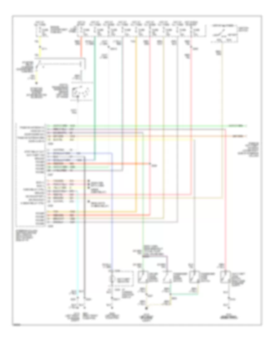
ANTI-LOCK BRAKES
Anti-lock Brake Wiring Diagrams for Lincoln Mark VIII 1997
 https://portal-diagnostov.com/license.html
Automotive Electricians Portal FZCO
Automotive Electricians Portal FZCO
https://portal-diagnostov.com/license.html
https://portal-diagnostov.com/license.html
Automotive Electricians Portal FZCO
Automotive Electricians Portal FZCOList of elements for Anti-lock Brake Wiring Diagrams for Lincoln Mark VIII 1997:
- (main harn, behind left side of i/p) s296
- (on abs module) abs pump motor
- Abs control module (lower left of engine compartment)
- Abs motor power
- Abs pump controls
- Brake on/off switch
- Brk on/off in
- C1030
- C208
- C246
- C293
- Check abs indicator
- Engine compartment fuse box
- Evac/fill connector
- Fuse 10a
- Fuse 15a
- Fuse 20a
- Fuse 30a
- G110 (lower left front corner of engine compartment)
- Ground
- Hot at all times
- Hot in run
- I/p fuse panel
- I/p warning indicator display
- Instrument cluster
- Left front abs wheel speed sensor
- Left rear abs wheel speed sensor
- Lft frt sol valve
- Lft frt spd sens
- Lft rr spd sens
- Message center
- Multiplex bus (+)
- Multiplex bus (-)
- Nca
- Power (run)
- Red
- Red/pnk
- Right front abs wheel speed sensor
- Right rear abs wheel speed sensor
- Rt frt spd sens
- Rt rr spd sens
- S102
- S164
- S227
- S232
- S255
- S295 (main harn, behind left side of i/p)
- Ta active indicator
- Ta disable indicator
- Tan/red
- Valve power
ANTI-THEFT
Anti-theft Wiring Diagram for Lincoln Mark VIII 1997
 https://portal-diagnostov.com/license.html
Automotive Electricians Portal FZCO
Automotive Electricians Portal FZCO
https://portal-diagnostov.com/license.html
https://portal-diagnostov.com/license.html
Automotive Electricians Portal FZCO
Automotive Electricians Portal FZCOList of elements for Anti-theft Wiring Diagram for Lincoln Mark VIII 1997:
- (body harn, near breakout to fuel pump/ fuel gauge sen) s344
- Acc
- Anti-theft hood switch (right side of engine compt)
- Anti-theft ind
- Anti-theft indicator
- Bus (+)
- Bus (-)
- C238
- C286
- C287
- C288
- C289
- Computer data lines
- Digital transmission range (dtr) sensor (left side of trans)
- Door ajar in
- Door disarm sw
- Driver door disarm switch
- Engine compartment fuse box
- Fuse 10a
- Fuse 15a
- Fuse 30a
- G101 (right front fender apron)
- G110 (left front of engine compt)
- G200 (left front floor pan)
- G203 (right front floor pan)
- Ground
- Headlights (hi beam relay)
- Hi beam relay ctrl
- Hood sw in
- Horn relay ctrl
- Horns (horn relay)
- Hot at all times
- Hot in run or start
- Hot in start
- I/p fuse panel
- I/p warning indicator display
- Ign (run/acc)
- Ign (run/start)
- Ignition switch
- Lock
- Passenger door ajar switch
- Passenger door disarm switch
- Passive antenna grd
- Passive antenna in
- Passive anti-theft antenna (lower right side of steering column)
- Power
- Run
- S102
- S111
- S2012
- S2017
- S283
- S285
- S291
- S293
- S307
- S602
- Start
- Starter relay (in engine compartment fuse box)
- Starting/ charging system (starter motor/ solenoid)
- Steering column/ ignition/lighting (scil) module (bottom right side of i/p)
- Strt relay out
- Tan
COMPUTER DATA LINES
Computer Data Lines for Lincoln Mark VIII 1997
 https://portal-diagnostov.com/license.html
Automotive Electricians Portal FZCO
Automotive Electricians Portal FZCO
https://portal-diagnostov.com/license.html
https://portal-diagnostov.com/license.html
Automotive Electricians Portal FZCO
Automotive Electricians Portal FZCOList of elements for Computer Data Lines for Lincoln Mark VIII 1997:
- (dash to head- lamp harn, left rear corner of engine compt) s140
- (engine sensor harn, near breakout to powertrain control module) s2020
- Anti-lock brake control module (lower left front of engine compt)
- Bus +
- Bus -
- C106
- C246
- C273
- C288
- C293
- C311
- C320
- C402
- C455
- Cellular telephone transceiver (below left rear side of package tray)
- Data link connector (dlc) (bottom left side of i/p)
- Driver's door module (ddm) (in driver's door)
- Driver's seat module (dsm) (under left front seat)
- Electronic automatic temperature control (eatc) module (behind center of i/p)
- Eprom pwr
- Evac & fill conn- ector (left engine compt)
- Fuse 10a
- G110 (left front of engine compt)
- G200 (left front floor pan)
- Hot at all times
- I/p fuse panel
- Instrument cluster
- Message center
- Passenger's seat module (psm) (under right front seat)
- Powertrain control module (pcm) (behind left side of i/p)
- S100
- S141 (dash to head- lamp harn, left rear corner of engine compt)
- S2005
- S2019 (engine sensor harn, near breakout to powertrain control module)
- S295 (main harn, near breakout to tilt relay)
- S296 (main harn, near breakout to tilt relay)
- S321 (body harn, near breakout to ground 200, left front floor pan)
- S338 (body harn, near breakout to ground g200, left front floor pan)
- Steering column/ ignition/lighting control module (scil) (bottom right side of i/p)
- Variable load control module (vlcm) (lower front center of engine compt)
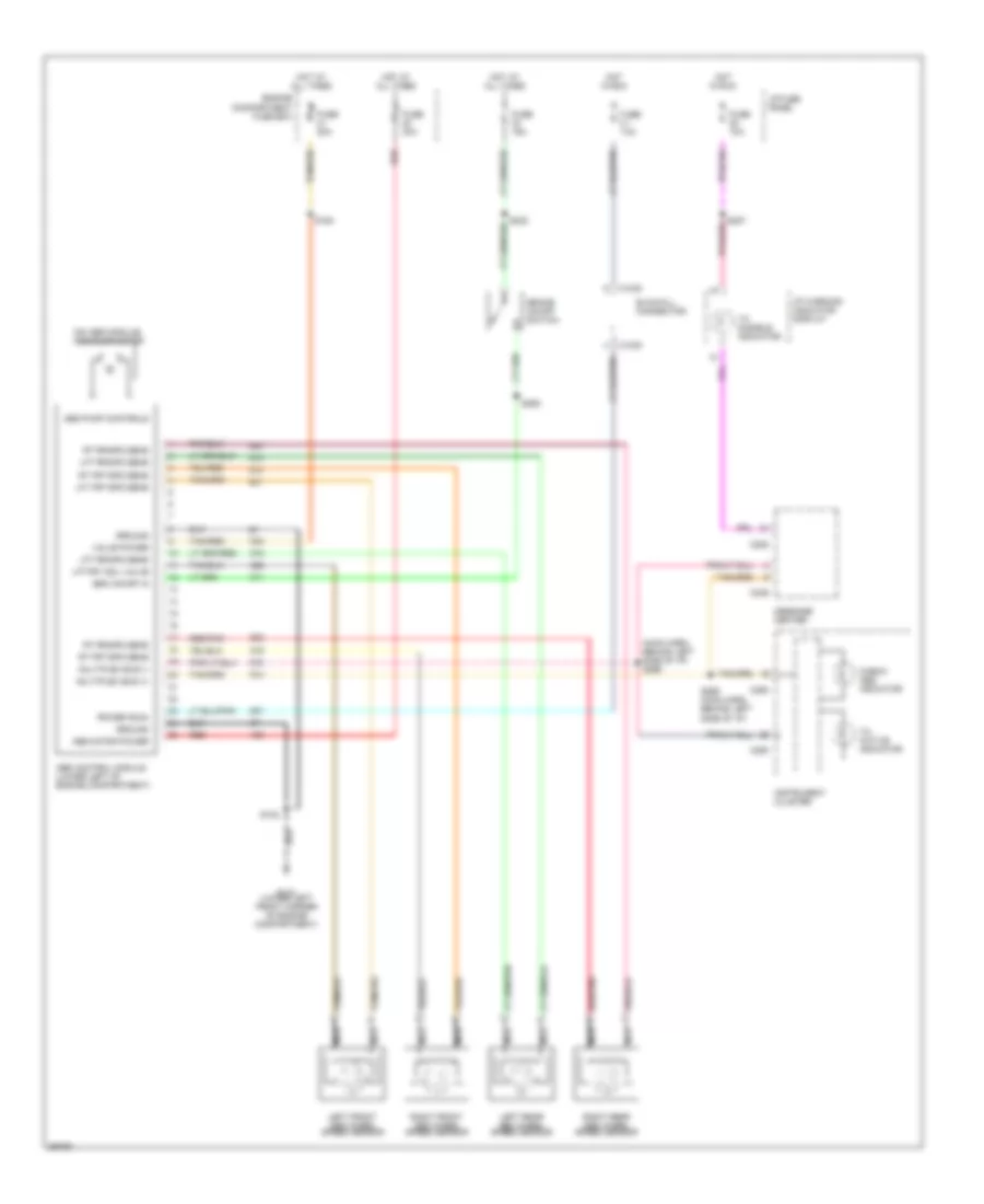
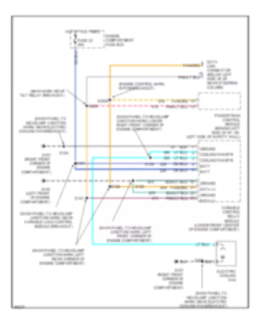
COOLING FAN
Cooling Fan Wiring Diagram for Lincoln Mark VIII 1997
 https://portal-diagnostov.com/license.html
Automotive Electricians Portal FZCO
Automotive Electricians Portal FZCO
https://portal-diagnostov.com/license.html
https://portal-diagnostov.com/license.html
Automotive Electricians Portal FZCO
Automotive Electricians Portal FZCOList of elements for Cooling Fan Wiring Diagram for Lincoln Mark VIII 1997:
- (dash panel to headlamp junction harn, left front corner of engine compartment)
- (dash panel to headlamp junction harn, left rear corner of engine compartment)
- (dash panel to headlamp junction harn, lower right front corner of engine compartment)
- (dash panel to headlamp junction harn, near electric cooling fan breakout)
- (dash panel to headlamp junction harn, near variable load control module breakout)
- (engine control harn, in pcm breakout)
- (main harn, near tilt relay breakout)
- Batt
- Compartment)
- Cooling fan mtr
- Data (+)
- Data (-)
- Electric cooling fan
- Engine compartment fuse box
- Fuse 23 40a
- G100 (left front of engine compartment)
- G101 (right front corner of engine
- Ground
- Hot at all times
- Link connector (below left side of i/p near steering column)
- Module (lower front center of engine compartment)
- Powertrain control module (behind left side of i/p, on left side of safety wall)
- S104
- S139
- S140
- S141
- S161
- S165
- S2020
- S296
- Variable control relay
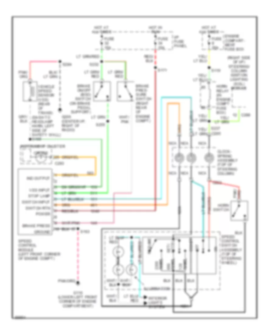
CRUISE CONTROL
Cruise Control Wiring Diagram for Lincoln Mark VIII 1997
 https://portal-diagnostov.com/license.html
Automotive Electricians Portal FZCO
Automotive Electricians Portal FZCO
https://portal-diagnostov.com/license.html
https://portal-diagnostov.com/license.html
Automotive Electricians Portal FZCO
Automotive Electricians Portal FZCOList of elements for Cruise Control Wiring Diagram for Lincoln Mark VIII 1997:
- (right side of i/p) steering/ column ignition lighting (scil) module
- Brake on/off (boo) switch (on brake pedal support)
- Brake pres- sure switch (right rear of engine compt)
- Brake press
- C222
- C288
- C293
- C295
- Clock- spring assembly (top of steering column)
- Coast
- Cruise
- Engine compart- ment fuse box
- Fuse 15a
- Fuse 20a
- G110 (lower left front corner of engine compartment)
- G206 (center i/p, right of radio)
- Ground
- Horn relay (in engine compt fuse box)
- Horn switch
- Hot at all times
- Hot in run
- I/p fuse panel
- Illumination
- Ind output
- Instrument cluster
- Interior lights system
- Nca
- Off
- Ohms
- Power
- Resume
- S110
- S163
- S171
- S232
- S255
- S284
- Set/ accel
- Speed control module (left front corner of engine compt)
- Speed control switch assembly (top of steering wheel)
- Stop lamp
- Switch input
- Switch rtn
- Vehicle speed sensor (vss) (rear of trans)
- Vss input
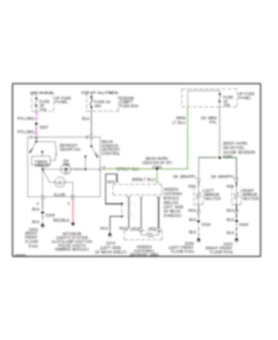
DEFOGGERS
Defogger Wiring Diagram for Lincoln Mark VIII 1997
 https://portal-diagnostov.com/license.html
Automotive Electricians Portal FZCO
Automotive Electricians Portal FZCO
https://portal-diagnostov.com/license.html
https://portal-diagnostov.com/license.html
Automotive Electricians Portal FZCO
Automotive Electricians Portal FZCOList of elements for Defogger Wiring Diagram for Lincoln Mark VIII 1997:
- (body harn, near fuel gauge sender) s250
- (main harn, center of i/p) s250
- Defrost on/off sw
- Engine compt fuse box
- Fuse 10a
- Fuse 24 40a
- G200 (left front floor pan)
- G203 (right front floor pan)
- G314 (left side of rear shelf)
- Hidden antenna module (below left side of rear window)
- Hidden antenna/ defrost grid
- Hot at all times
- Hot in run
- I/p fuse panel
- Illum
- Interior lights system (autolamp switch/ pulse width dimming module)
- Left mirror heater
- Nca
- On ind
- Rear window defrost control
- Right mirror heater
- S209
- S227
- S500
- S600
- Timing circuit
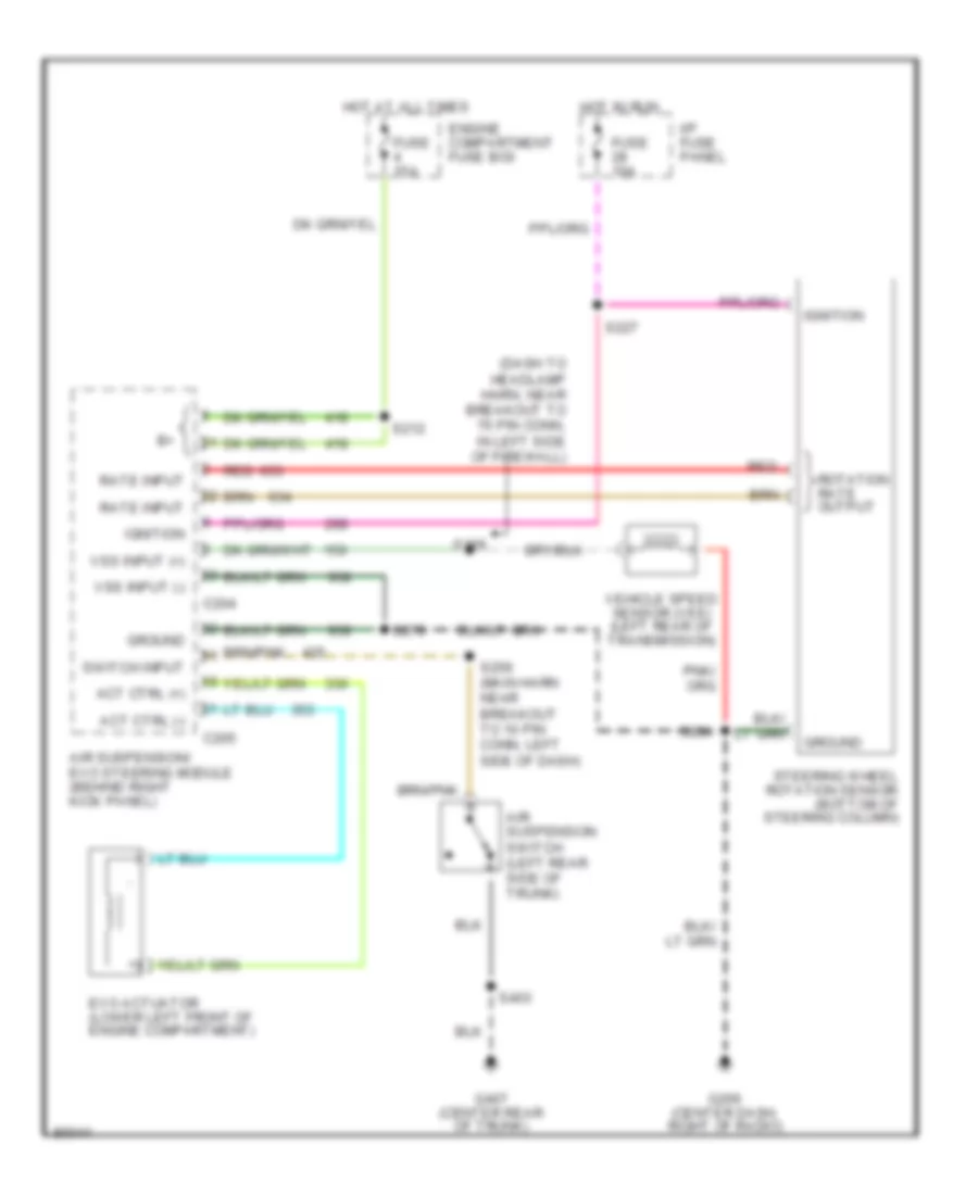
ELECTRONIC POWER STEERING
Electronic Power Steering Wiring Diagram for Lincoln Mark VIII 1997
 https://portal-diagnostov.com/license.html
Automotive Electricians Portal FZCO
Automotive Electricians Portal FZCO
https://portal-diagnostov.com/license.html
https://portal-diagnostov.com/license.html
Automotive Electricians Portal FZCO
Automotive Electricians Portal FZCOList of elements for Electronic Power Steering Wiring Diagram for Lincoln Mark VIII 1997:
- (dash to headlamp harn, near breakout to 76 pin conn, in left side of firewall)
- Act ctrl (+)
- Act ctrl (-)
- Air suspension switch (left rear side of trunk)
- Air suspension/ evo steering module (behind right kick panel)
- C204
- C205
- Engine compartment fuse box
- Evo actuator (lower left front of engine compartment)
- Fuse 10a
- Fuse 15a
- G206 (center dash, right of radio)
- G407 (center rear of trunk)
- Ground
- Hot at all times
- Hot in run
- I/p fuse panel
- Ignition
- Rate input
- Red
- Rotation rate output
- S169
- S212
- S227
- S256 (main harn near breakout to 10 pin conn, left side of dash)
- S279
- S284
- S403
- Steering wheel rotation sensor (bottom of steering column)
- Switch input
- Vehicle speed sensor (vss) (left rear of transmission)
- Vss input (+)
- Vss input (-)
ELECTRONIC SUSPENSION
Electronic Suspension Wiring Diagram for Lincoln Mark VIII 1997
 https://portal-diagnostov.com/license.html
Automotive Electricians Portal FZCO
Automotive Electricians Portal FZCO
https://portal-diagnostov.com/license.html
https://portal-diagnostov.com/license.html
Automotive Electricians Portal FZCO
Automotive Electricians Portal FZCOList of elements for Electronic Suspension Wiring Diagram for Lincoln Mark VIII 1997:
- (base of steering column)
- (behind right kick panel)
- (center
- (center dash, right of radio)
- (center of
- (dash to hdlmp
- (left rear of transmission)
- (left rear side
- (lower left front of engine compt)
- (lower right front
- (lwr left
- (main harn,
- (right
- (right frt
- (top of right
- 10a
- 15a
- 60a
- Air spring sol
- Air susp sw input
- Air suspension
- Air suspension compressor
- Air suspension/
- Air suspension/evo steering module
- All times
- Apron)
- Battery power
- Box
- Brake sensor)
- Breakout to
- Center
- Compressor relay
- Compressor rly ctrl
- Compt
- Compt)
- Corner of engine compt)
- Courtesy lts
- Dash, right
- Diagnostic input
- Door open input
- Engine
- Evo actuator
- Evo actuator feed
- Evo module)
- Evo test conn
- Fender
- Floor
- Front
- Front wheelwell)
- Frt corner
- Fuse
- G101
- G110
- G203
- G206
- G407
- Ground
- Harn, left side
- Harn, near
- Height sensor
- Hgt sens ground
- Hgt sensor power
- Hot
- Hot at
- I/p
- Ignition on input
- In run
- L fnt hgt sens input
- L fnt sol output
- L rear sol output
- Left front
- Left rear
- Left side
- Message
- Message center
- Message center output
- Motor/vent solenoid
- Nca
- Of dash)
- Of engine
- Of engine compt)
- Of firewall)
- Of radio)
- Of trunk)
- Pan)
- Panel
- Pnk
- Pnk 421
- Rear
- Rear height
- Rear hgt sens input
- Red
- Red 633
- Right front
- Right rear
- Rotation sensor
- Rt fnt hgt sens input
- Rt fnt sol output
- Rt rear sol output
- S104
- S142
- S143
- S163
- S169
- S212
- S227
- S256
- S257
- S279
- S284
- S303
- S403
- Sensor
- Solid
- State
- Steering rotate input
- Steering wheel
- Switch
- Tan
- Tan 424
- Vehicle speed input +
- Vehicle speed input -
- Vehicle speed sensor
- Vent sol ctrl
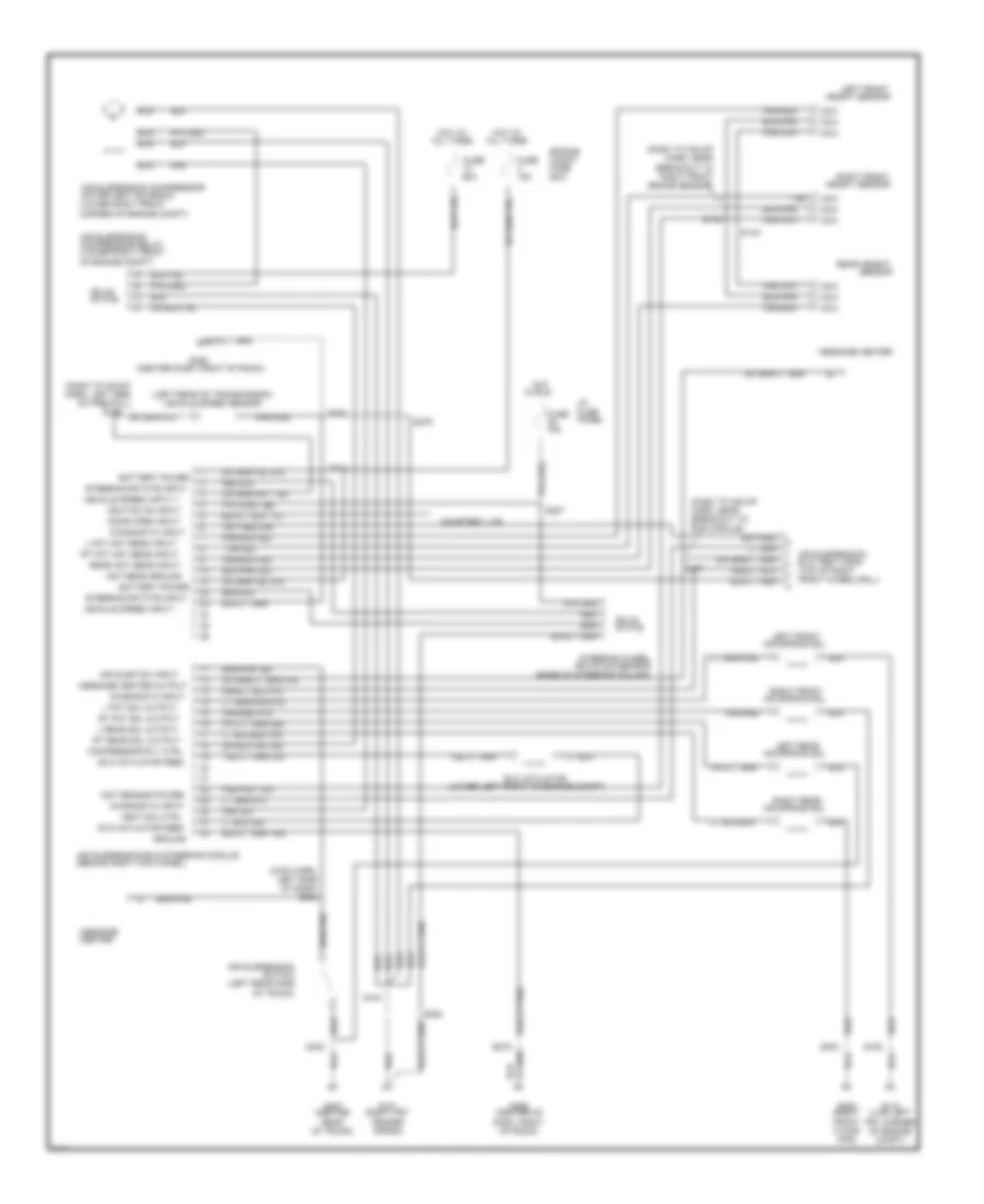
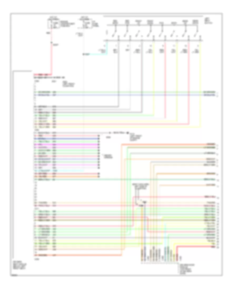
ENGINE PERFORMANCE
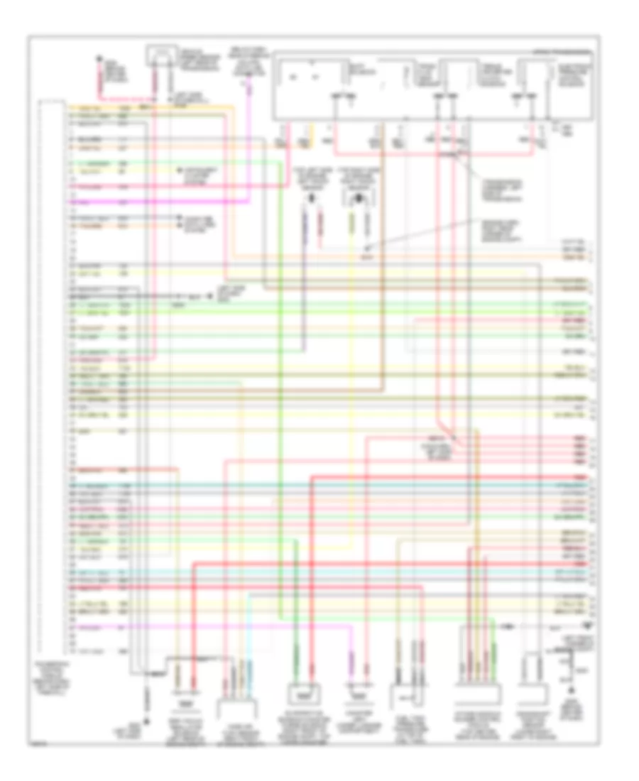
4.6L
4.6L, Engine Performance Wiring Diagrams (1 of 4) for Lincoln Mark VIII 1997
 https://portal-diagnostov.com/license.html
Automotive Electricians Portal FZCO
Automotive Electricians Portal FZCO
https://portal-diagnostov.com/license.html
https://portal-diagnostov.com/license.html
Automotive Electricians Portal FZCO
Automotive Electricians Portal FZCOList of elements for 4.6L, Engine Performance Wiring Diagrams (1 of 4) for Lincoln Mark VIII 1997:
- (below dash,
- (engine harn, right rear corner of engine compt)
- (left front corner of engine compt)
- (left side of dash) g202
- (left side of firewall) s169
- (main harn, left side of dash)
- (top left side of engine) left knock sensor
- (top right side of engine) right knock sensor
- (transmission harness, left side of transmission)
- 4r70w transmission
- Canister vent (under luggage compartment)
- Computer data lines system
- Crankshaft position sensor (lower right front of engine)
- Egr vacuum regulator solenoid (left rear of engine compt)
- Electronic pressure control solenoid
- Evaporative emission canister purge solenoid (right front of engine compt, top vapor canister)
- Fuel tank pressure transducer (in top of fuel tank)
- G100
- G202 (left side of dash)
- G206 (behind center of dash)
- G206 (behind center of dash)
- Instrument cluster system
- Intake manifold runner control module (top center rear of engine)
- Mass air flow sensor (right front of engine compt)
- Nca
- Near steering column) data link connector
- Powertrain control module (behind dash, left side of firewall)
- Red
- Red/pnk
- S108
- S125
- S131
- S200
- S2018
- S213
- S284
- Shift solenoid
- Torque converter clutch solenoid
- Trans. fluid temp. sensor
- Vehicle speed sensor (left rear of transmission)
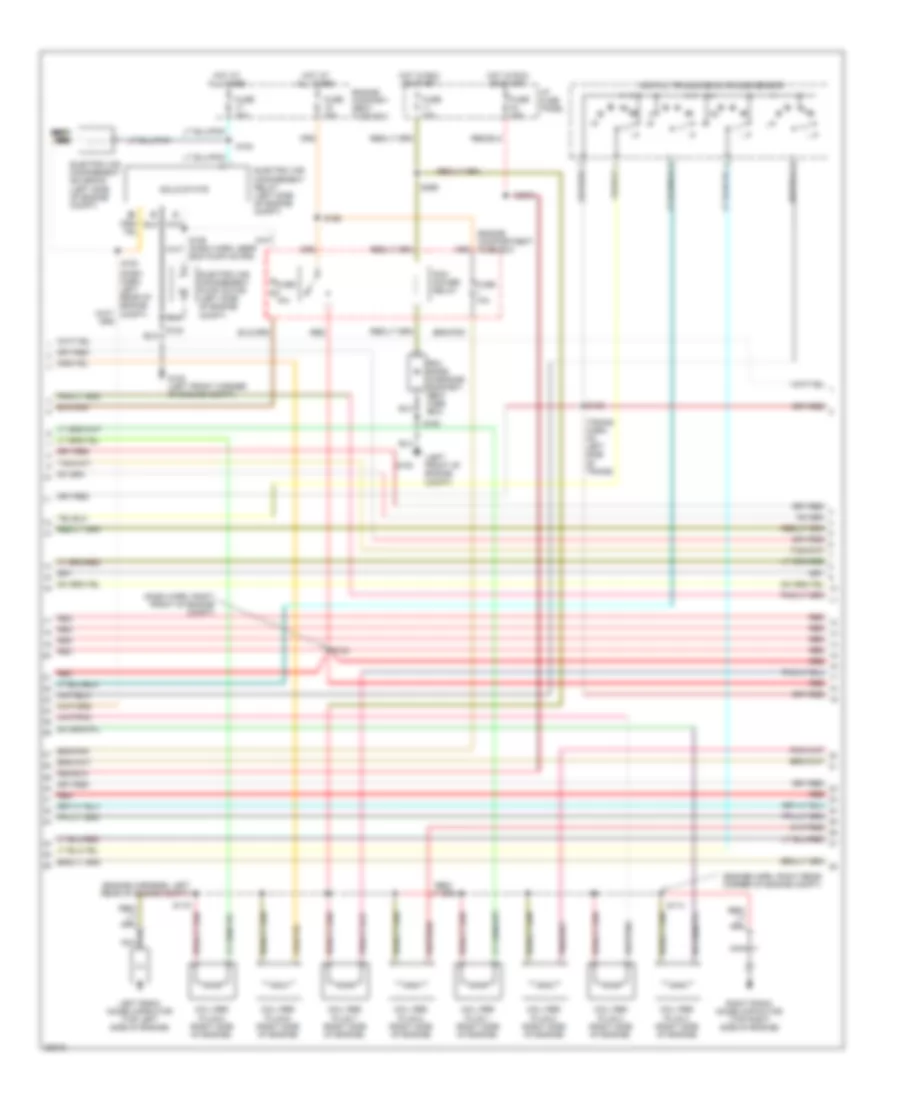
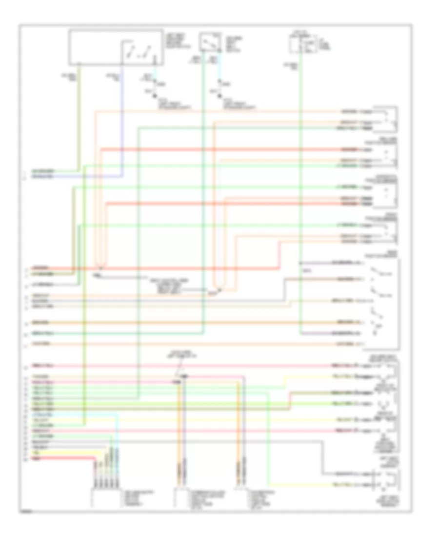
4.6L, Engine Performance Wiring Diagrams (2 of 4) for Lincoln Mark VIII 1997
 https://portal-diagnostov.com/license.html
Automotive Electricians Portal FZCO
Automotive Electricians Portal FZCO
https://portal-diagnostov.com/license.html
https://portal-diagnostov.com/license.html
Automotive Electricians Portal FZCO
Automotive Electricians Portal FZCOList of elements for 4.6L, Engine Performance Wiring Diagrams (2 of 4) for Lincoln Mark VIII 1997:
- (dash harn left rear of engine compt)
- (dash harn, right front of engine compt)
- (engine harn, right rear corner of engine compt)
- (engine harness, left rear of engine compt)
- (left front of engine compt)
- (trans harn, on left side of trans)
- C c c c c c c c c c c c c c c c c c c c
- Coil per plug 1 (right side of engine)
- Coil per plug 2 (right side of engine)
- Coil per plug 3 (right side of engine)
- Coil per plug 4 (right side of engine)
- Coil per plug 5 (right side of engine)
- Coil per plug 6 (right side of engine)
- Coil per plug 7 (right side of engine)
- Coil per plug 8 (right side of engine)
- D d d d d d d d d d d d d d d d d d d d
- Digital transmission range sensor
- Electric air management pump motor (left side of engine compt)
- Electric air management relay (left side of engine compt)
- Electric air management solenoid (left side of engine compt)
- Engine compart- ment fuse box
- Engine compartment fuse box
- Fuse 10a
- Fuse 15a
- Fuse 30a
- G100
- G100 (left front corner of engine compt)
- Hot at all times
- Hot in run or start
- I/p fuse panel
- Left radio noise capacitor (top left side of engine)
- Nca
- Pcm diode (in engine compart- ment fuse box)
- Pcm power relay
- Red
- Right radio noise capacitor (top right side of engine)
- S102
- S114
- S119
- S124
- S133
- S153
- S154
- S155 (dash harn, near eam pump motor)
- S163
- S168
- S2003
- S299
- Solid state
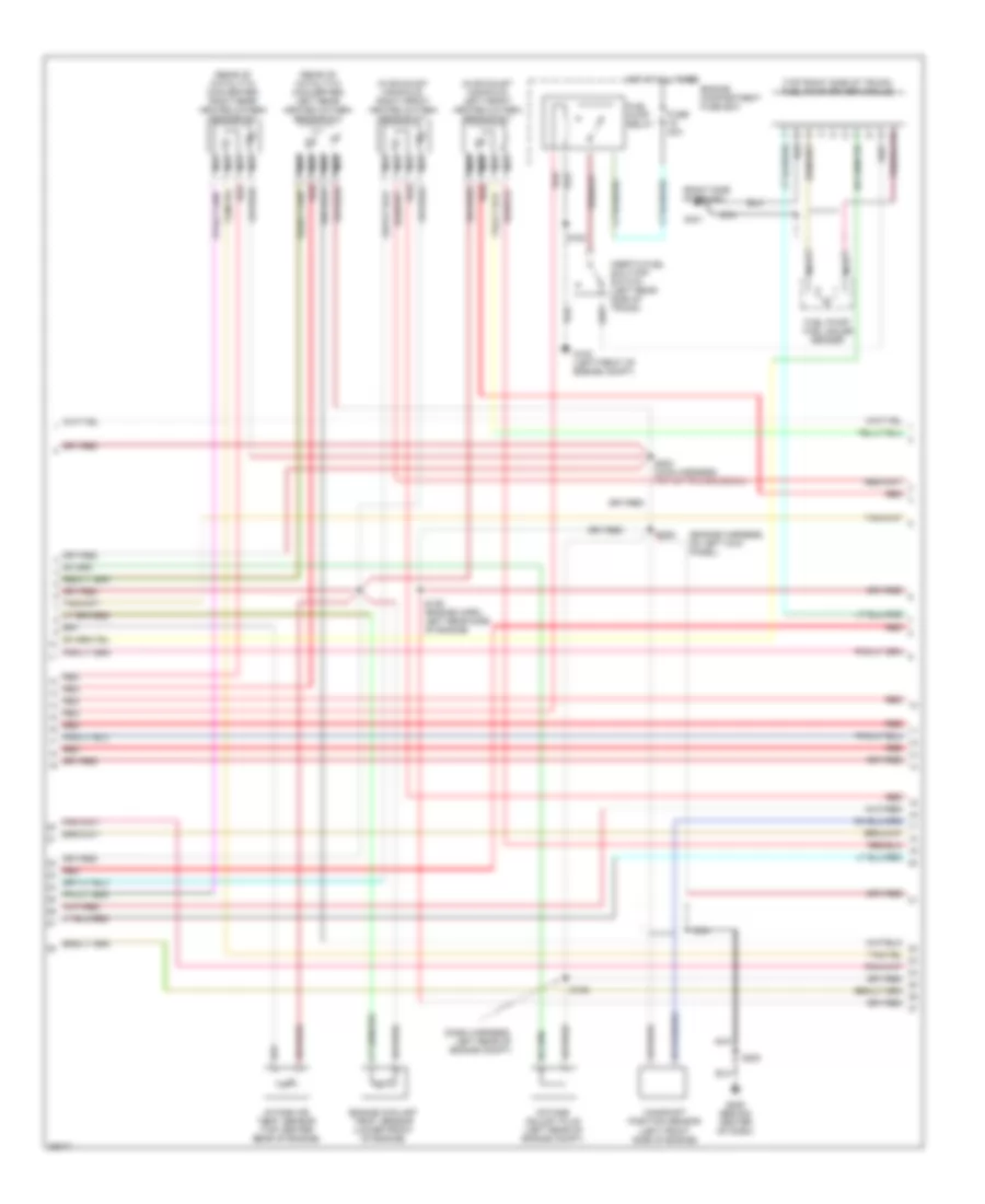
4.6L, Engine Performance Wiring Diagrams (3 of 4) for Lincoln Mark VIII 1997
 https://portal-diagnostov.com/license.html
Automotive Electricians Portal FZCO
Automotive Electricians Portal FZCO
https://portal-diagnostov.com/license.html
https://portal-diagnostov.com/license.html
Automotive Electricians Portal FZCO
Automotive Electricians Portal FZCOList of elements for 4.6L, Engine Performance Wiring Diagrams (3 of 4) for Lincoln Mark VIII 1997:
- (dash harness, left rear of engine compt)
- (engine harness, on left kick panel)
- (in exhaust manifold) left front heated oxygen sensor #21
- (in exhaust manifold) right front heated oxygen sensor #11
- (rear of catalytic converter) left rear heated oxygen sensor #12
- (rear of catalytic converter) right rear heated oxygen sensor #22
- (right side of trunk)
- (top right side of trunk) fuel pump driver module
- Camshaft position sensor (left front side of engine)
- Engine compartment fuse box
- Engine coolant temp. sensor (lower front of engine)
- Fuel pump relay
- Fuel pump/ fuel gauge sender
- Fuse 20a
- G100 (left front of engine compt)
- G206 (behind center of dash)
- G401
- Hot at all times
- Inertia fuel shut-off switch (left rear side of trunk)
- Intake air temp. sensor (top center rear of engine)
- Nca
- Octane adjust plug (left rear of engine compt)
- Red
- S129 (engine harn, left rear side of engine)
- S156
- S163
- S200
- S202 (main harness, top of transmission)
- S252
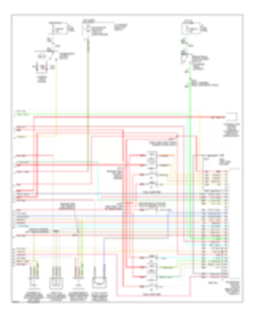
4.6L, Engine Performance Wiring Diagrams (4 of 4) for Lincoln Mark VIII 1997
 https://portal-diagnostov.com/license.html
Automotive Electricians Portal FZCO
Automotive Electricians Portal FZCO
https://portal-diagnostov.com/license.html
https://portal-diagnostov.com/license.html
Automotive Electricians Portal FZCO
Automotive Electricians Portal FZCOList of elements for 4.6L, Engine Performance Wiring Diagrams (4 of 4) for Lincoln Mark VIII 1997:
- (center rear of engine) idle air control valve
- (dash harn, right front corner of eng compt)
- (eng harn, top rt side of eng)
- (engine harn, left rear of engine compt)
- (engine harn, top left side of engine)
- (engine harness, left rear of engine)
- (on brake pedal support)
- 1998 only
- A/c refrigerant pressure sensor (right front of engine compt)
- Brake pedal position (bpp) switch
- Differential pressure feed- back egr sensor (left rear of engine)
- Fuel injectors
- Fuse 29 10a
- Fuse 32 15a
- G202 (left side of dash)
- Hot at all times
- Hot in run
- Hot in run or start
- I/p fuse panel
- I/p warning indicator display
- Interior lights system
- Malfunction indicator lamp (mil) (check engine)
- Output shaft speed sensor (left side of transmission)
- Powertrain control module (behind dash, left side of firewall)
- Red
- S124
- S126
- S127
- S132
- S137
- S213
- S232
- S308
- S419 (body harness, front center of trunk)
- Tan
- Tan/red
- Throttle position sensor (top center rear of engine)
- Transmission control switch
- Variable load control module (lower front center of engine compt)
EXTERIOR LIGHTS
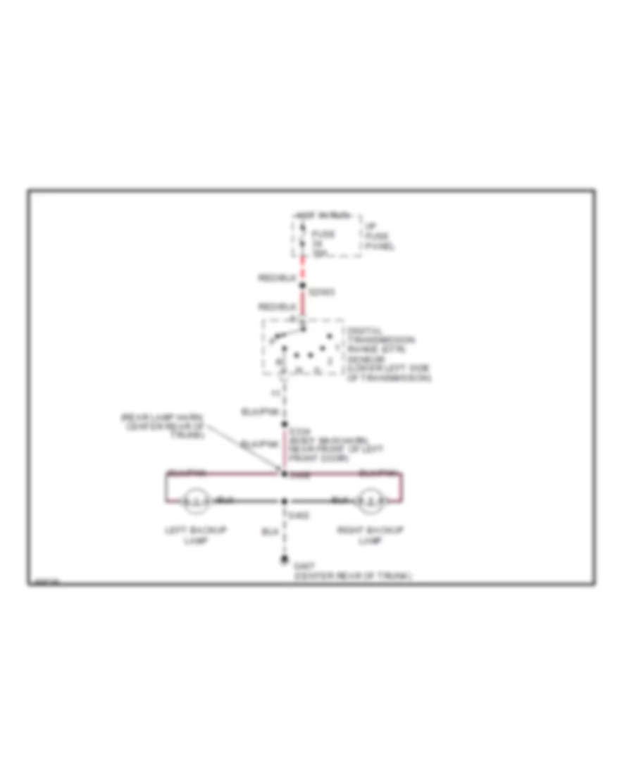
Back-up Lamps Wiring Diagram for Lincoln Mark VIII 1997
 https://portal-diagnostov.com/license.html
Automotive Electricians Portal FZCO
Automotive Electricians Portal FZCO
https://portal-diagnostov.com/license.html
https://portal-diagnostov.com/license.html
Automotive Electricians Portal FZCO
Automotive Electricians Portal FZCOList of elements for Back-up Lamps Wiring Diagram for Lincoln Mark VIII 1997:
- (rear lamp harn, center rear of trunk)
- Digital transmission range (dtr) sensor (lower left side of transmission)
- Fuse 15a
- G407 (center rear of trunk)
- Hot in run
- I/p fuse panel
- Left backup lamp
- Right backup lamp
- S2003
- S402
- S408
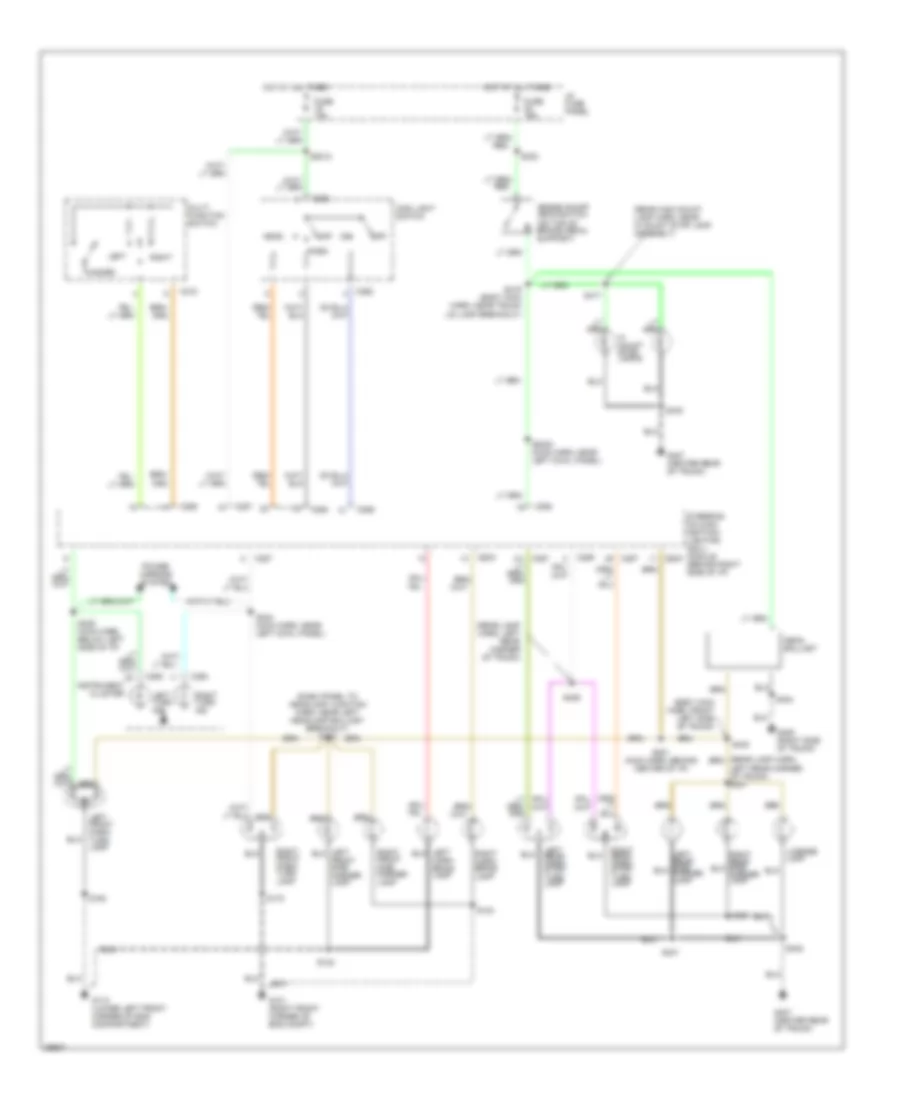
Exterior Lamps Wiring Diagram for Lincoln Mark VIII 1997
 https://portal-diagnostov.com/license.html
Automotive Electricians Portal FZCO
Automotive Electricians Portal FZCO
https://portal-diagnostov.com/license.html
https://portal-diagnostov.com/license.html
Automotive Electricians Portal FZCO
Automotive Electricians Portal FZCOList of elements for Exterior Lamps Wiring Diagram for Lincoln Mark VIII 1997:
- (body main harn, front left side of trunk)
- (dash panel to headlamp junction harn, near left headlamp ballast breakout) s152
- (rear high mount lamp harn, near hi mount stop lamp assembly)
- (rear lamp harn, left rear corner of trunk)
- Brake on/off (boo) switch (on top of brake pedal support)
- C215
- C262
- C286
- C287
- C288
- C289
- C293
- C294
- Corn- ering lamp
- Fuse 10a
- Fuse 15a
- G101 (right front corner of eng compt)
- G110 (lower left front corner of eng compartment)
- G405 (right side of trunk)
- G407 (center rear of trunk)
- Hazard
- Head
- Hi mount stop lamps
- Hot at all times
- I/p fuse panel
- Instrument cluster
- Left
- Left front park/ turn lamp
- Left rear corner of trunk) s427
- Left rear park/ stop/ turn lamp
- Left turn ind
- License lamp
- Main light switch
- Multi function switch
- Neon ballast
- Off
- Park
- Power mirrors system
- Right
- Right corn- ering lamp
- Right front park/ turn lamp
- Right front side marker lamp
- Right rear park/ stop/ turn lamp
- Right turn ind
- S102
- S104
- S163
- S172
- S2000 (main harn, near left cowl panel)
- S2012
- S232
- S244 (main harn, near left cowl panel)
- S249 (main harn, below left side of i/p)
- S281 (main harn, behind center of i/p)
- S400
- S401
- S402
- S404
- S417
- S419 (body main harn, near trunk lid lamp breakout)
- S423
- S426
- S433
- Steering column/ ignition/ lighting (scil) module (behind right side of i/p)
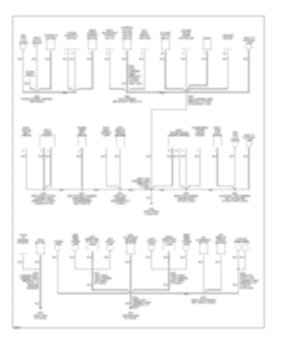
GROUND DISTRIBUTION
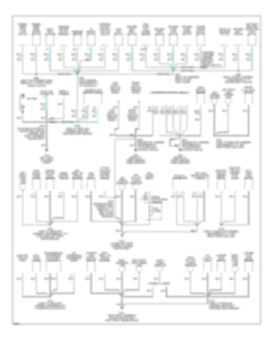
Ground Distribution Wiring Diagram (1 of 3) for Lincoln Mark VIII 1997
 https://portal-diagnostov.com/license.html
Automotive Electricians Portal FZCO
Automotive Electricians Portal FZCO
https://portal-diagnostov.com/license.html
https://portal-diagnostov.com/license.html
Automotive Electricians Portal FZCO
Automotive Electricians Portal FZCOList of elements for Ground Distribution Wiring Diagram (1 of 3) for Lincoln Mark VIII 1997:
- (courtesy lamp feed harness, near driv- er's seat memory switch) s508
- A/c clutch coil
- Air suspension compressor motor/vent solenoid
- Air suspension compressor relay
- Anti- theft hood switch
- Anti-lock brake control module
- Battery
- Brake fluid level switch
- Cam- shaft position sensor shield
- Crank- shaft position sensor shield
- Data link connector
- Driver's door ajar switch
- Driver's door disarm switch
- Driver's door module
- Driver's seat belt switch
- Driver's seat module
- Dual note horns
- Electric air man- agement pump motor
- Electric air man- agement relay
- Electric cooling fan
- Ends in harness
- Engine compartment fuse box
- Engine coolant level sensor
- Evac/fill connector
- Fuel pump relay
- Fuel pump/ fuel gauge sender
- G101 (right front corner of engine compartment right front fender apron)
- G110 (left front of engine compt)
- G110 (lower left front corner of engine compartment)
- G204 (behind i/p, near steering wheel bracket)
- I/p dimming swtch
- Instu- ment cluster
- Intake manifold runner control module
- Left ballast lo beam headlamp
- Left corner- ing lamp
- Left front air spring solenoid
- Left front park/ turn lamp
- Left front side marker lamp
- Left hi beam headlamp
- Left seat forward/ rearward dump switch
- Main light swtch
- Mass air flow sensor
- Message center
- Message center switch assembly
- Nca
- Passen- ger's door ajar switch
- Passen- ger's door disarm switch
- Pcm diode
- Pcm power relay
- Power mirror adjust switch
- Powertrain control module
- Right ballast lo beam headlamp
- Right cornering lamp
- Right front air spring solenoid
- Right front park/ turn lamp
- Right front side marker lamp
- Right hi beam headlamp
- S100 (starter motor relay and battery ground harness, left front corner of engine compt)
- S102 (dash to headlamp harness, near breakout to left front park/turn lamp)
- S104 (dash to headlamp harness, near breakout to electric cooling fan)
- S108 (engine control harness, near breakout to egr vacuum regulator solenoid)
- S163 (dash to headlamp harness, near breakout to c189, near left front brake sensor)
- S165 (dash to headlamp harness, near left forward crash sensor)
- S172 (dash to headlamp harness, near right forward crash sensor)
- S200 (engine ctrl harness, near breakout to powertrain control module)
- S213 (engine ctrl harness, near breakout to powertrain control module)
- S291 (main harness, near breakout to tele relay)
- S307 (body main harness, front of left front door)
- S360 (seat control harness, near breakout to driver's seat module)
- S602 (body main harness, near breakout to right front window motor)
- Speed control module
- Steering column/ ignition/ lighting module
- Trunk lid release switch
- Variable load control module
- W/ drl
- W/o drl
- Washer fluid level sensor
- Washer pump motor
- Wind- shield wiper motor
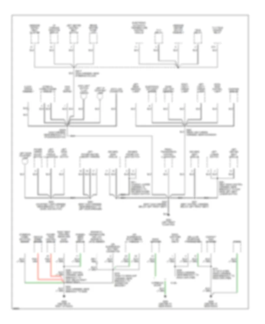
Ground Distribution Wiring Diagram (2 of 3) for Lincoln Mark VIII 1997
 https://portal-diagnostov.com/license.html
Automotive Electricians Portal FZCO
Automotive Electricians Portal FZCO
https://portal-diagnostov.com/license.html
https://portal-diagnostov.com/license.html
Automotive Electricians Portal FZCO
Automotive Electricians Portal FZCOList of elements for Ground Distribution Wiring Diagram (2 of 3) for Lincoln Mark VIII 1997:
- 87a
- Air suspension/ evo steering module
- Air suspension/ evo test connector
- Automatic temperature control module
- Brake shifter inter- lock
- Cellular telephone transceiver
- Clock- cpring assembly
- Compact disc changer
- Compass module
- Data link connector
- Dome/ map lamp assembly
- Driver's door module
- Driver's power win- dow switch
- Driver's seat module
- Electronic
- Electronic day/night mirror
- Engine oil temperature and low engine oil level sensor
- G200 (left front floor pan)
- G206 (center i/p, near radio)
- G206 (center i/p, right of radio)
- I/p warning indicator display
- Intreval wiper/washer module
- Left door courtesy lamp
- Left door handle illumination
- Left door lock switch
- Left heated control seat switch
- Left heated seat module
- Left i/p courtesy lamp
- Left lumbar switch
- Left power heated memory mirrors
- Left rear reading lamp
- Left vanity mirror lamp
- Main light switch
- Main light switch illum- ination
- Message center switch assembly
- Message instru- ment cluster
- Moon- roof control unit
- Passen- ger's seat module
- Power mirror adjust switch
- Power- train control module
- Prndl/ transmission control illumination
- Radio
- Radio amplifier
- Radio amplifier (w/ jbl only)
- Right seat forward/ rearward dump switch
- Right vanity mirror lamp
- S2005 (main harness, near breakout to i/p dimming switch)
- S2017 (main harness, near steering column)
- S279 (dash to headlamp harness, near breakout to connector bracket)
- S284 (main harness, near breakout to g206)
- S300 (body main harness, below left front seat)
- S301 (seat control harness, below left front seat)
- S356 (seat control harness, near breakout to c327, below right front seat)
- S361 (seat back control harness, near breakout to c345 near left seat lumbar switch)
- S406 (radio harness, near breakout to radio amplifier)
- S410 (w/ cd player) (radio harness, near breakout to radio amplifier)
- S500 (body main harness, near breakout to left door speaker)
- S503 (courtesy lamp harness, near breakout to left door lock switch)
- S511 (window jumper harness, in breakout to driver's power window switch)
- S900 (rear view mirror harness, near moonroof)
- Steering wheel rotation sensor
- Tele relay
- Tilt relay
- Tilt/tele common relay
- Vehicle speed sensor
- W/jbl
- W/premium sound
Ground Distribution Wiring Diagram (3 of 3) for Lincoln Mark VIII 1997
 https://portal-diagnostov.com/license.html
Automotive Electricians Portal FZCO
Automotive Electricians Portal FZCO
https://portal-diagnostov.com/license.html
https://portal-diagnostov.com/license.html
Automotive Electricians Portal FZCO
Automotive Electricians Portal FZCOList of elements for Ground Distribution Wiring Diagram (3 of 3) for Lincoln Mark VIII 1997:
- (body main harness, near breakout to g203) s302
- Air bag diagnostic monitor
- Air suspension switch
- Ash tray illum ination
- Blower motor speed controller
- Blower mototr relay
- Cigarette lighter
- Column/ ignition/ lighting module
- Day/ night sensor amplifier
- Fuel filler door release solenoid
- G203 (right front floor pan)
- G405 (right side of trunk)
- G407 (center rear of trunk)
- Hi mount stop lamps
- Left backup lamp
- Left rear air spring solenoid
- Left rear park/ stop/turn lamp
- Left rear side marker lamp
- License lamp
- Message center
- Neon ballast
- Passen- ger's seat module
- Passenger's power window switch
- Power point
- Radio
- Radio static ground
- Rear window defrost control
- Right backup lamp
- Right door lock switch
- Right heated seat control switch
- Right heated seat module
- Right i/p courtesy lamp
- Right lumbar switch
- Right power/heated memory mirrors
- Right rear air spring solenoid
- Right rear park/ stop/turn lamp
- Right rear reading lamp
- Right rear side marker lamp
- S208 (main harness, near breakout to right i/p courtesy lamp)
- S209 (main harness, behind right sde of i/p)
- S283 (main harness, near breakout to right i/p cour- tesy lamp)
- S303 (body main harness, near breakout to g203)
- S304 (seat control harness, near breakout to passenger's seat module)
- S306 (console panel harness, near radio)
- S362 (seat back control harness, near breakout to right lumbar switch)
- S400 (right rear lamp harness, right rear of trunk)
- S401 (left rear lamp harness, left rear of trunk)
- S402 (rear lamp harness, near breakout to g407)
- S403 (body main harness, left side of trunk)
- S404 (luggage compt harness, near breakout to trunk lid release solenoid)
- S433 (rear high mount lamp harness, near breakout to hi mount stop lamp)
- S600 (body main harness, center front of right door)
- S603 (courtesy lamp harness, bottom center of right front door)
- Steering
- Trunk lid release solenoid
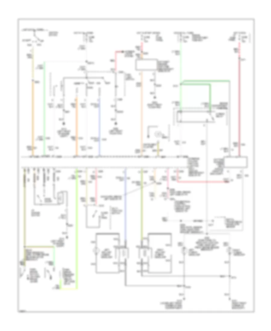
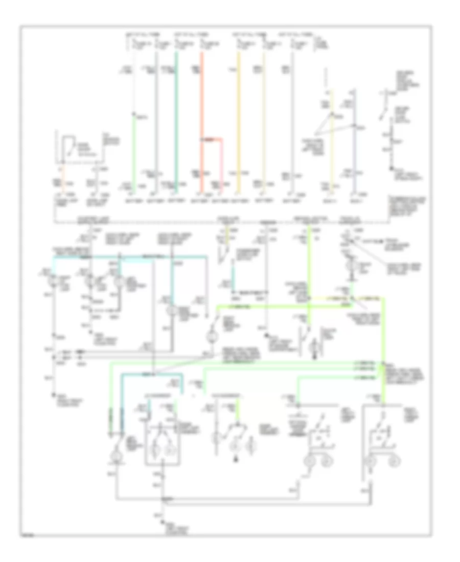
HEADLIGHTS
Headlight Wiring Diagram, with DRL for Lincoln Mark VIII 1997
 https://portal-diagnostov.com/license.html
Automotive Electricians Portal FZCO
Automotive Electricians Portal FZCO
https://portal-diagnostov.com/license.html
https://portal-diagnostov.com/license.html
Automotive Electricians Portal FZCO
Automotive Electricians Portal FZCOList of elements for Headlight Wiring Diagram, with DRL for Lincoln Mark VIII 1997:
- (main harn, behind left side of i/p)
- Acc
- C215
- C217
- C262
- C286
- C287
- C288
- C289
- C291
- Day/night sensor/ amplifier (behind right side of i/p)
- Daytime running lamps (drl) module (front of eng compt)
- Digital transmission range (dtr) sensor
- Dome on/off
- Engine compartment fuse box
- Flass to pass
- Fuse 10a
- Fuse 15a
- G101 (right front corner of eng compt)
- G110 (left front of engine compt)
- G110 (lower left front corner of eng compartment)
- G200 (left front floor pan)
- G203 (right front floor pan)
- Head
- Headlamp
- Hi beam
- Hi beam relay
- Hot at all times
- Hot in run
- Hot in start or run
- I/p dimming switch
- I/p fuse panel
- Ignition switch
- Instrument cluster
- Interior lights system
- Left ballast
- Left hi beam headlamp
- Lo beam
- Main light switch
- Multi function switch
- Nca
- Off
- Park
- Park brake release motor (below left side of i/p)
- Park brake switch (on park brake lever)
- Powertrain control module (pcm) (behind left side of i/p)
- Red
- Red/
- Right ballast
- Right hi beam headlamp
- Run
- S121
- S162 (dash panel to headlamp junction harn, near left front brake sensor breakout)
- S163
- S171
- S172
- S2005
- S2012
- S209
- S252 (eng cntrl sensor harn, near conn bracket breakout)
- S282
- S291
- S293
- S295
- S296 (main harn, behind left side of i/p)
- Start
- Steering column/ ignition/ lighting (scil) module (behind right side of i/p)
Headlight Wiring Diagram, without DRL for Lincoln Mark VIII 1997
 https://portal-diagnostov.com/license.html
Automotive Electricians Portal FZCO
Automotive Electricians Portal FZCO
https://portal-diagnostov.com/license.html
https://portal-diagnostov.com/license.html
Automotive Electricians Portal FZCO
Automotive Electricians Portal FZCOList of elements for Headlight Wiring Diagram, without DRL for Lincoln Mark VIII 1997:
- C215
- C262
- C286
- C287
- C288
- C293
- Day/night sensor/ amplifier (behind right side of i/p)
- Dome on/off
- Engine compartment fuse box
- Flass to pass
- Fuse 10a
- Fuse 15a
- G101 (right front corner of eng compt)
- G110 (left front of engine compt)
- G110 (lower left front corner of eng compartment)
- G200 (left front floor pan)
- G203 (right front floor pan)
- Head
- Headlamp
- Hi beam
- Hi beam relay
- Hot at all times
- Hot in start or run
- I/p dimming switch
- I/p fuse panel
- Instrument cluster
- Interior lights system
- Left ballast
- Left hi beam headlamp
- Lo beam
- Main light switch
- Multi function switch
- Nca
- Off
- Park
- Red/
- Right ballast
- Right hi beam headlamp
- S121
- S162 (dash panel to headlamp junction harn, near left front brake sensor breakout)
- S163
- S172
- S2005
- S2012
- S209
- S291
- S293
- Steering column/ ignition/ lighting (scil) module (behind right side of i/p)
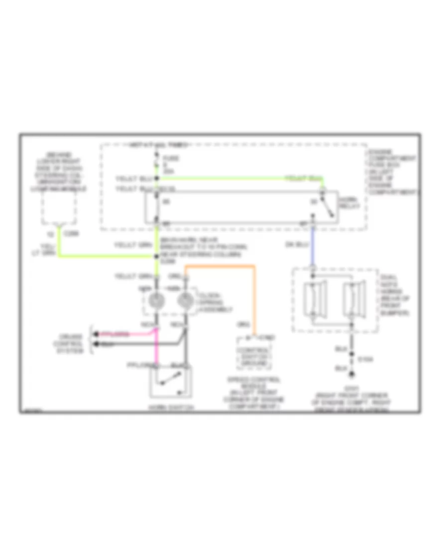
HORN
Horn Wiring Diagram for Lincoln Mark VIII 1997
 https://portal-diagnostov.com/license.html
Automotive Electricians Portal FZCO
Automotive Electricians Portal FZCO
https://portal-diagnostov.com/license.html
https://portal-diagnostov.com/license.html
Automotive Electricians Portal FZCO
Automotive Electricians Portal FZCOList of elements for Horn Wiring Diagram for Lincoln Mark VIII 1997:
- (behind lower right side of dash) steering col- umn/ignition/ lighting module
- (main harn, near breakout to 10 pin conn, near steering column) s298
- C103
- C288
- Clock- spring assembly
- Control switch ground
- Cruise control system
- Dual note horns (rear of front bumper)
- Engine compartment fuse box (in left side of engine compartment)
- Fuse 20a
- G101 (right front corner of engine compt, right front fender apron)
- Horn relay
- Horn switch
- Hot at all times
- Nca
- S104
- Speed control module (in left front corner of engine compartment)
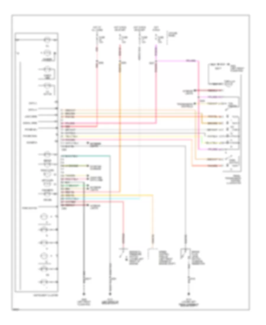
INSTRUMENT CLUSTER
Instrument Cluster Wiring Diagram for Lincoln Mark VIII 1997
 https://portal-diagnostov.com/license.html
Automotive Electricians Portal FZCO
Automotive Electricians Portal FZCO
https://portal-diagnostov.com/license.html
https://portal-diagnostov.com/license.html
Automotive Electricians Portal FZCO
Automotive Electricians Portal FZCOList of elements for Instrument Cluster Wiring Diagram for Lincoln Mark VIII 1997:
- Brake
- Brake fluid level switch (in brake reservoir)
- C293
- C294
- Charge
- Check abs
- Computer data lines
- Cruise
- D/2
- Data (+)
- Data (-)
- Dimmer in
- Engine oil pressure switch (lower left front of engine)
- Exterior exterior lights lights
- Exterior lights
- Fuse 10a
- G110 (left front of engine compt)
- G110 (lower left front corner of engine compt)
- G200 (left front floor pan)
- High beam
- Hot at all times
- Hot in run
- Hot in run or start
- I/p fuse panel
- Instrument cluster
- Interior lights
- Left turn
- Oil
- Park switch
- Power (b+)
- Power (run)
- Prndl/ transmission control illumination
- Red
- Right turn
- S2017
- S227
- S292
- S293
- S308
- Speed control module (left front corner of engine compt)
- Starting/ charging
- Ta active
- Tcs illum
- Tcs switch
- Transmission controls
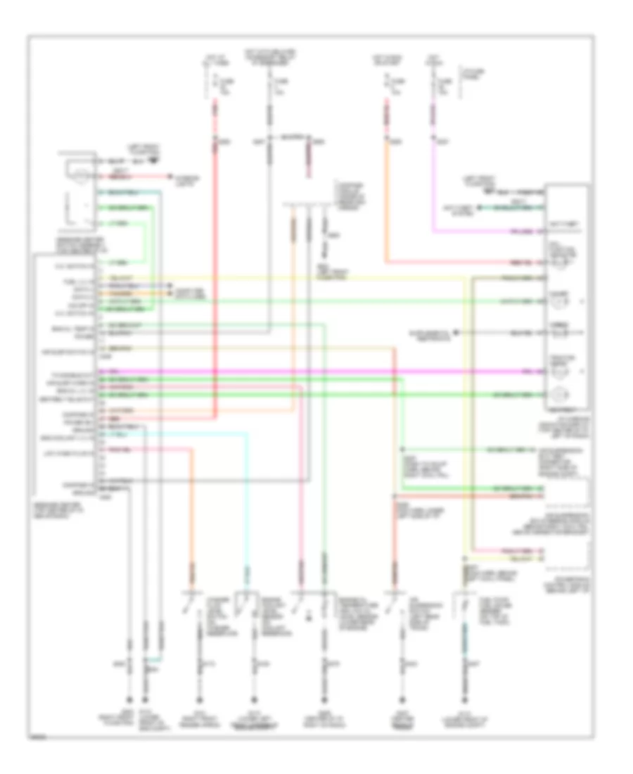
Message Center Wiring Diagram for Lincoln Mark VIII 1997
 https://portal-diagnostov.com/license.html
Automotive Electricians Portal FZCO
Automotive Electricians Portal FZCO
https://portal-diagnostov.com/license.html
https://portal-diagnostov.com/license.html
Automotive Electricians Portal FZCO
Automotive Electricians Portal FZCOList of elements for Message Center Wiring Diagram for Lincoln Mark VIII 1997:
- (left front floor pan) g200
- (right front floor pan)
- Air susp switch in
- Air susp warn in
- Air suspension switch (left rear side of trunk)
- Air suspension/ evo steering module (behind right cowl pnl, above connector bracket)
- Air suspension/ evo test connector (right side of engine compt)
- Airbag
- Anti-theft
- Anti-theft system
- C208
- C246
- Compass in
- Compass module (inside of rearview mirror)
- Computer data lines
- Data (+)
- Data (-)
- Eng coolant lvl in
- Eng oil lvl in
- Eng oil temp in
- Engine coolant level sensor (on coolant reservoir)
- Engine oil temperature and low oil level sensor (lower rear of engine)
- Fuel lvl in
- Fuel pump/ fuel gauge sender (on top of fuel tank)
- Fuse 10a
- G101 (right front fender apron)
- G110 (lower front of engine compt)
- G110 (lower left front corner of engine compt)
- G200 (left front floor pan)
- G203 g110 (lower front of eng compt)
- G206 (center of i/p, right of radio)
- G407 (center rear of trunk)
- Ground
- Hot at all times
- Hot in run
- Hot in run or start
- Hot with delayed accessory relay #1 energized
- I/p fuse panel
- I/p warning indicator display (top center of i/p, left of radio)
- Interior lights
- Low wash fluid in
- M.c. switch in
- Mal- function indicator
- Message center (top center of i/p, above radio)
- Message center switch assembly (top center of i/p)
- O/d off
- O/d off in
- Power
- Power (b+)
- Powertrain control module (behind left i/p)
- Red
- S2017
- S208
- S227
- S256 main harn, under left side of i/p)
- S257 (dash to hdlmp harn, behind right cowl pnl)
- S287
- S292
- S293
- S307 (main harn, behind left cowl panel)
- S900
- S906
- Seatbelt
- Seatbelt bulb out
- Ta disable out
- Traction assist
- Washer fluid level switch (on washer reservoir)
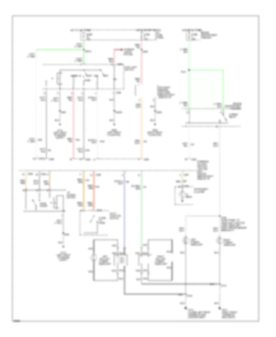
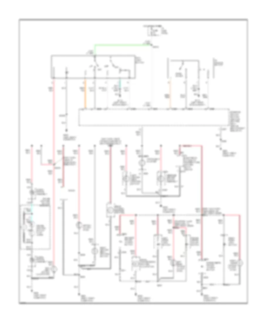
INTERIOR LIGHTS
Courtesy Lamps Wiring Diagram for Lincoln Mark VIII 1997
 https://portal-diagnostov.com/license.html
Automotive Electricians Portal FZCO
Automotive Electricians Portal FZCO
https://portal-diagnostov.com/license.html
https://portal-diagnostov.com/license.html
Automotive Electricians Portal FZCO
Automotive Electricians Portal FZCOList of elements for Courtesy Lamps Wiring Diagram for Lincoln Mark VIII 1997:
-
- right i/p ctsy lamp
- (main harn, behind left side of i/p) s2008
- (main harn, behind right side of i/p) s269
- (main harn, front of left front door)
- (main harn, near front left side of trunk)
- (main harn, near front of left front door)
- (main harn, near front of right front door)
- (rear view inside mirror harn, near left rear reading lamp breakout)
- Battery
- Bus (+)
- Bus (-)
- C263
- C286
- C287
- C288
- C289
- C455
- Demand lighting output
- Dome lamp feed
- Dome lamp sw input
- Dome on/off
- Dome/ map lamp assembly
- Door ajar input
- Driver door ajar switch
- Driver's door module (in driver's door)
- Fuse 1 10a
- Fuse 13 15a
- Fuse 19 10a
- Fuse 25 10a
- Fuse 26 10a
- Fuse 31 10a
- Fuse 7 15a
- G110 (left front of eng compt)
- G110 (left front of engine compartment)
- G200 (left front floor pan)
- G203 (right front floor pan)
- Glove box lamp
- Ground
- Hot at all times
- I/p dimming switch
- I/p fuse panel
- Left door courtesy lamp
- Left i/p ctsy lamp
- Left rear reading lamp
- Left vanity mirror lamp
- Nca
- Optional garage door opener
- Passenger door ajar switch
- Pnk/
- Red/
- Right door courtesy lamp
- Right rear reading lamp
- Right vanity mirror lamp
- S2005
- S2012
- S208
- S285
- S291
- S300
- S302
- S303
- S307
- S321
- S328
- S329
- S330
- S331
- S338
- S425
- S503
- S602
- S603
- S900
- S902 (rear view inside mirror harn, near left vanity mirror lamp breakout)
- Steering column/ ignition/lighting (scil) module (behind right side of i/p)
- Tan
- Trunk lid ajar input
- Trunk lid lamp
- Trunk lid release solenoid
- W/ moonroof
- W/o moonroof
Instrument Illumination Wiring Diagram for Lincoln Mark VIII 1997
 https://portal-diagnostov.com/license.html
Automotive Electricians Portal FZCO
Automotive Electricians Portal FZCO
https://portal-diagnostov.com/license.html
https://portal-diagnostov.com/license.html
Automotive Electricians Portal FZCO
Automotive Electricians Portal FZCOList of elements for Instrument Illumination Wiring Diagram for Lincoln Mark VIII 1997:
- (main harn, near air bag diagnostic monitor breakout) s286
- (main harn, near i/p dimming sw breakout)
- Astray illumin- ation
- C202
- C272
- C286
- C287
- C288
- C293
- C522
- C602
- Clock- spring assembly
- Cruise control switch assembly
- Cruise control switch illum lamps
- Dome on/off
- Driver's power window switch
- Electronic automatic temperature control (eatc) module
- Fuse 10a
- G110 (left front of eng compt)
- G200 (left front floor pan)
- G203 (right front floor pan)
- Hot at all times
- I/p fuse panel
- I/p dimming switch
- Instrument cluster
- Left door handle illumin- ation
- Left door lock switch
- Left heated seat control switch
- Main light switch
- Main light switch illumination
- Message center switch assembly
- Nca
- Near front of left front door) s314
- Off
- Passenger's power window switch
- Power mirror adjust switch
- Prndl transmission control illumination
- Radio
- Rear window defrost control
- Right door handle illumin- ation
- Right door lock switch
- Right heated seat control switch
- S2004
- S2005
- S2012
- S2017
- S208
- S209
- S283
- S291
- S300
- S306
- S503
- S511
- S600
- S603
- Steering column/ ignition/ lighting control (scil) module (behind right side of i/p)
MEMORY SYSTEMS
Memory Mirrors Wiring Diagram for Lincoln Mark VIII 1997
 https://portal-diagnostov.com/license.html
Automotive Electricians Portal FZCO
Automotive Electricians Portal FZCO
https://portal-diagnostov.com/license.html
https://portal-diagnostov.com/license.html
Automotive Electricians Portal FZCO
Automotive Electricians Portal FZCOList of elements for Memory Mirrors Wiring Diagram for Lincoln Mark VIII 1997:
- (body main harn, left side of floor pan)
- (body main harn, near left front door speaker)
- (main harn, left side of i/p)
- C311
- C362
- C455
- C456
- Defogger system
- Directional control switch
- Driver's door module (top front of driver's door)
- Driver's seat memory switch
- Driver's seat module (below left front seat)
- Electronic day/night mirror
- Engine compartment fuse box
- Exterior lights system
- Fuse 10a
- Fuse 30a
- G110 (left front of engine compt)
- G200 (left front floor pan)
- G203 (right front floor pan)
- Hot at all times
- I/p fuse panel
- Interior lights system
- Keyless entry keypad switch assembly
- Left/power/heated/ memory mirror
- Left/right
- Mirror select switch
- Nca
- Off
- Position sensors
- Power mirror adjust switch
- Powertrain control module (left side of i/p)
- Red
- Right/power/heated memory mirror
- S2007
- S295
- S296
- S301
- S321
- S338
- S340 (body main harn, left front floor pan)
- S348
- S357
- S360
- S500
- S503
- S508
- S510
- S600
- S958
- Solid state
- Steering column/ ignition/lighting module (right side of i/p)
- Up/down
Memory Seat Wiring Diagram (1 of 2) for Lincoln Mark VIII 1997
 https://portal-diagnostov.com/license.html
Automotive Electricians Portal FZCO
Automotive Electricians Portal FZCO
https://portal-diagnostov.com/license.html
https://portal-diagnostov.com/license.html
Automotive Electricians Portal FZCO
Automotive Electricians Portal FZCOList of elements for Memory Seat Wiring Diagram (1 of 2) for Lincoln Mark VIII 1997:
- (body main harn, left side of floor pan)
- Back
- C311
- C350
- C355
- C362
- C455
- C456
- Driver's door module (top front of driver's door)
- Driver's seat module (below left front seat)
- Engine compartment fuse box
- Front down
- Front up
- Fuse 10a
- Fuse 30a
- Fwd
- G110 (left front of engine compt)
- G200 (left front floor pan)
- Hot at all times
- I/p fuse panel
- Left seat switch
- Memory mirrors
- Rear down
- Rear up
- Rec back
- Rec fwd
- Red
- S2007
- S301
- S321
- S338
- S357
- S360
Memory Seat Wiring Diagram (2 of 2) for Lincoln Mark VIII 1997
 https://portal-diagnostov.com/license.html
Automotive Electricians Portal FZCO
Automotive Electricians Portal FZCO
https://portal-diagnostov.com/license.html
https://portal-diagnostov.com/license.html
Automotive Electricians Portal FZCO
Automotive Electricians Portal FZCOList of elements for Memory Seat Wiring Diagram (2 of 2) for Lincoln Mark VIII 1997:
- (main harn, left side of i/p)
- (seat control feed jumper harn, below left front seat)
- Driver's seat belt switch
- Driver's seat memory switch
- Front of seat motor
- Front position sensor
- Fuse 10a
- G110 (left front of engine compt)
- Horizontal position sensor
- Hot at all times
- I/p fuse panel
- Keyless entry keypad switch assembly
- Left seat back motor assembly
- Left seat forward/ reward dump switch
- Left seat motor assembly
- Nca
- Off
- Powertrain control module (left side of i/p)
- Rear of seat motor
- Rear position sensor
- Recliner position sensor
- Red
- S295
- S296
- S319
- S320
- S360
- S510
- Seat forward/ backward motor
- Steering column/ ignition/lighting module (right side of i/p)
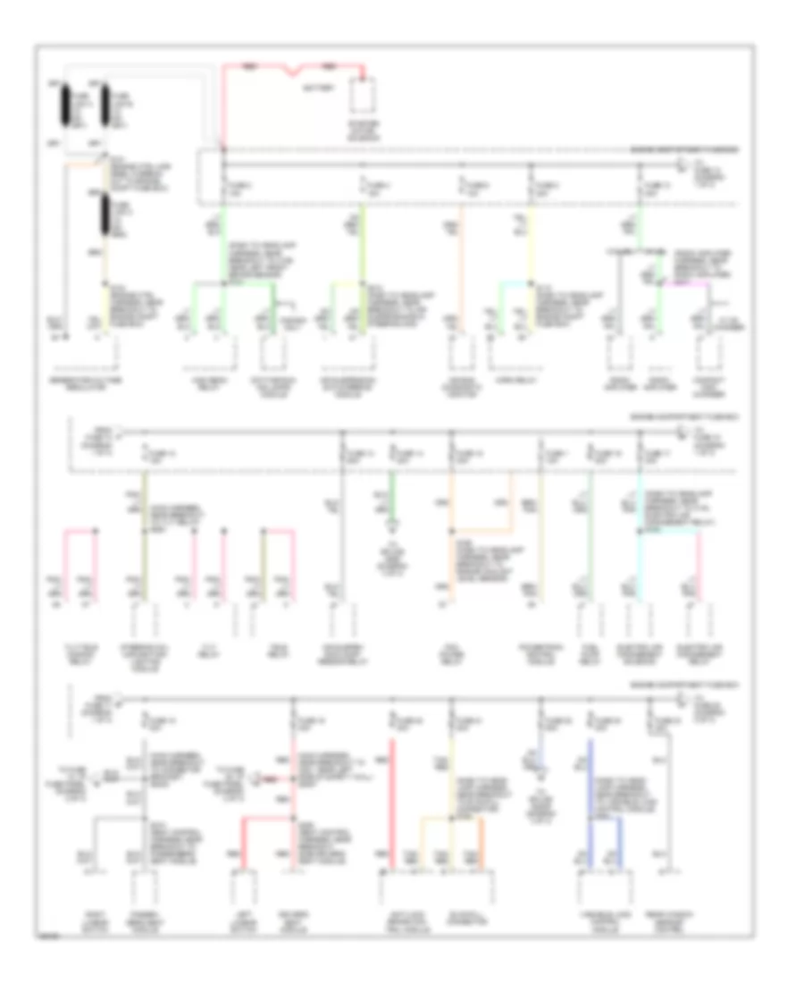
POWER DISTRIBUTION
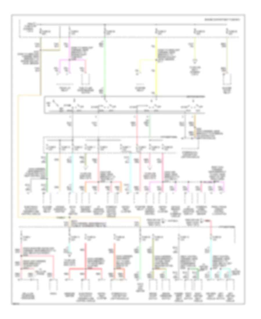
Power Distribution Wiring Diagram (1 of 3) for Lincoln Mark VIII 1997
 https://portal-diagnostov.com/license.html
Automotive Electricians Portal FZCO
Automotive Electricians Portal FZCO
https://portal-diagnostov.com/license.html
https://portal-diagnostov.com/license.html
Automotive Electricians Portal FZCO
Automotive Electricians Portal FZCOList of elements for Power Distribution Wiring Diagram (1 of 3) for Lincoln Mark VIII 1997:
- (dash to head- lamp harness, near breakout to evac/fill connector) s164
- (dash to head- lamp harness, near breakout to variable load control module) s161
- (dash to headlamp harness, near breakout to c140, electric air management relay) s154
- (dash to headlamp harness, near breakout to c189, near left front brake sensor) s121
- (main harness, near breakout to c201, near left side of safety wall) s2007
- (main harness, near breakout to connector bracket) s2002
- (main harness, near breakout to tilt relay) s294
- (radio amplifier harness, near breakout to radio amplifier) s411
- Air bag diagnostic monitor
- Air suspen- sion comp- ressor relay
- Air suspension/ evo steering module
- Anti-lock brake con- trol module
- Battery
- Canada only
- Compact disc changer
- Daytime run- ing lamps module
- Driver's seat module
- Electric air management relay
- Electric air management solenoid
- Engine compartment fuse box
- Evac/fill connector
- From a fuse 10 (diagram 1 of 3)
- From b fuse 17 (diagram 1 of 3)
- Fuel pump relay
- Fuse 1 10a
- Fuse 10 20a
- Fuse 12 15a
- Fuse 13 60a
- Fuse 14 30a
- Fuse 15 30a
- Fuse 16 20a
- Fuse 17 30a
- Fuse 18 30a
- Fuse 19 30a
- Fuse 2 15a
- Fuse 20 30a
- Fuse 21 20a
- Fuse 22 60a
- Fuse 23 40a
- Fuse 24 40a
- Fuse 4 15a
- Fuse 6 10a
- Fuse 8 20a
- Generator/voltage regulator
- High beam relay
- Horn relay
- Left lumbar switch
- Passen- ger's seat module
- Pcm power relay
- Powertrain control module
- Radio amplifier
- Rear window defrost control
- Red
- Right lumbar switch
- S101 (engine ctrl har- ness, in break- out to engine compt fuse box)
- S103 (engine ctrl harness, near breakout to engine compt fuse box)
- S110 (dash to headlamp harness, near breakout to engine compt fuse box)
- S168 (dash to headlamp harness, near breakout to engine coolant level sensor)
- S212 (dash to headlamp harness, near breakout to air suspension/evo steering mod)
- S310 (seat control harness, near breakout to passenger's seat module)
- S358 (seat control harness, near breakout side driver's seat module)
- Starter motor/ solenoid
- Steering col- umn/ignition/ lighting module
- Tan/ red
- Tele relay
- Tilt relay
- Tilt/tele common relay
- To fuse 12 (diagram 1 of 3)
- To fuse 12, i/p fuse panel (diagram 2 of 3)
- To fuse 18 (diagram 1 of 3)
- To fuse 25 (diagram 2 of 3)
- To fuse 35, i/p fuse panel (diagram 2 of 3)
- To splice s2009 (diagram 3 of 3)
- To splice s290 (diagram 3 of 3)
- Variable load control module
- W/ cd changer
- W/ jbl
- W/o jbl
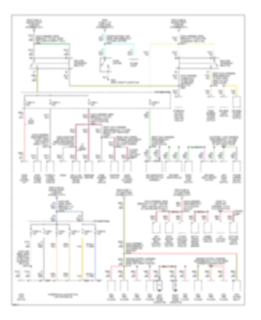
Power Distribution Wiring Diagram (2 of 3) for Lincoln Mark VIII 1997
 https://portal-diagnostov.com/license.html
Automotive Electricians Portal FZCO
Automotive Electricians Portal FZCO
https://portal-diagnostov.com/license.html
https://portal-diagnostov.com/license.html
Automotive Electricians Portal FZCO
Automotive Electricians Portal FZCOList of elements for Power Distribution Wiring Diagram (2 of 3) for Lincoln Mark VIII 1997:
- (body main harness, near breakout to g300, near front of left front door)
- (dash to headlamp harness, near breakout to engine compt fuse box) s166
- (dash to headlamp harness, near breakout to engine coolant level sensor) s111
- (main har- ness, near breakout to tele relay) s293
- (main har- ness, near breakout to tilt relay) s227
- (main harness, near break- out to c290, behind right side of i/p) s285
- (main harness, near breakout to c298, near park brake release motor) s232
- (main harness, near breakout to electric auto temp control mod) s288
- (main harness, near breakout to instrument cluster) s292
- (radio amp harness, near breakout to radio amp) s2021
- (radio booster and eq amp harness, near breakout to c223, below glove box) s226
- (seat control harness, near breakout to c352, below left front seat) s357
- (seat control harness, near breakout to passenger's seat module) s359
- Acc
- Air bag diagnostic monitor
- Air sus- pension evo steering module
- Blower motor relay
- Brake on/off switch
- Brake pressure switch
- Cellular telephone tranciever
- Data link con- nector
- Day/night sensor/ amplifier
- Driver's seat module
- Electronic automatic temperature control module
- Engine compartment fuse box
- Evac/ fill con- nector
- From c fuse 24 (diagram 1 of 3)
- From splice s2002 (diag- ram 1 of 3)
- From splice s2007 (diag- ram 1 of 3)
- Fuel filler door release switch
- Fuse 11 10a
- Fuse 12 10a
- Fuse 14 30a
- Fuse 15 10a
- Fuse 17 10a
- Fuse 2 10a
- Fuse 20 10a
- Fuse 21 10a
- Fuse 25 60a
- Fuse 26 15a
- Fuse 26 20a
- Fuse 27 30a
- Fuse 28 10a
- Fuse 28 30a
- Fuse 29 40a
- Fuse 32 15a
- Fuse 34 15a
- Fuse 35 10a
- Fuse 38 10a
- Fuse 5 10a
- Fuse 6 10a
- Fuse 9 10a
- I/p fuse panel
- I/p warning indicator display
- Ignition switch
- Instru- ment cluster
- Key in
- Key out
- Left heated seat module
- Left seat switch
- Message center
- Off
- Passen- ger's seat module
- Prndl/trans- mission control illumination
- Radio
- Rear window defrost control
- Red
- Right heated seat module
- Right seat switch
- Run
- S167 (dash to headlamp harness, near breakout to engine coolant level sensor)
- S2010 (main harness, near breakout to delay accessory relay #2)
- S282 (main harness, near breakout to steering column/ignition/ lighting module)
- Start
- Starter relay
- Steering col- umn/ignition/ lighting module
- Steering column/ ignition/ lighting module
- Steering wheel rotation sensor
- To splice s2003 (diag- ram 3 of 3)
- To splice s2011 (diagram 3 of 3)
- To splice s299 (diag- ram 3 of 3)
- To splice s323 (diag- ram 3 of 3)
- Trunk lid relay
- W/ cellular phone
- W/ heated seats
Power Distribution Wiring Diagram (3 of 3) for Lincoln Mark VIII 1997
 https://portal-diagnostov.com/license.html
Automotive Electricians Portal FZCO
Automotive Electricians Portal FZCO
https://portal-diagnostov.com/license.html
https://portal-diagnostov.com/license.html
Automotive Electricians Portal FZCO
Automotive Electricians Portal FZCOList of elements for Power Distribution Wiring Diagram (3 of 3) for Lincoln Mark VIII 1997:
- (body main harness, near breakout to c308, behind left rear side panel) s363
- (body main harness, near breakout to driver's door module) s506
- (body main harness, near breakout to g300, near front of left front door) s322
- (console panel har- ness, near breakout to cigar lighter) s323
- (courtesy lamp harness, near breakout to c506, near bottom center of left front door) s510
- (dash to headlamp harness, to a/c cycling switch) s171
- (engine control harness, near breakout to c166, rear corner of engine compt) s114
- (engine control harness, near breakout to c175, near left front ho2s #21) s119
- (main har- ness, near breakout to delayed accessory relay #2) s2012
- (main har- ness, near breakout to tele relay) s2009
- (main harness, in breakout to delayed accessory relay #1) s289
- (main harness, near breakout to c201, near left side of safety wall) s2014
- (main harness, near breakout to c201, near left side of safety wall) s290
- (main harness, near breakout to c276, to air bag diag- nostic monitor) s287
- (main harness, near breakout to connector bracket) s299
- (main harness, near breakout to delayed accessory relay #2) s2011
- (main harness, near breakout to i/p dimming switch) s2003
- (main harness, near breakout to left heated seat control switch) (w/ heated seats only) s2015
- (radio booster and eq amp har- ness, near break- out to connector) s233
- (rear view mirror harness, near break- out to electronic day/night mirror) s906
- A/c cycling switch
- C287
- C289
- Canada only
- Cellular telephone trans- ceiver
- Cigar lighter
- Coil per plug #1
- Coil per plug #2
- Coil per plug #3
- Coil per plug #4
- Coil per plug #5
- Coil per plug #6
- Coil per plug #7
- Coil per plug #8
- Compass module
- Daytime running lamps module
- Delayed accessory relay #1
- Delayed accessory relay #2
- Digital trans- mission range sensor
- Driver's door module
- Driver's power window switch
- Driver's seat memory switch
- Elec- tronic day/night mirror
- From fuse 11, i/p fuse panel (diagram 2 of 3)
- From fuse 14, engine compt fuse box (diagram 1 of 3)
- From fuse 14, i/p fuse panel (diagram 2 of 3)
- From fuse 22, engine compt fuse box (diagram 1 of 3)
- From fuse 28, engine compt fuse box (diagram 2 of 3)
- From fuse 34, i/p fuse panel (diagram 2 of 3)
- Fuse 1 10a
- Fuse 10 30a
- Fuse 13 15a
- Fuse 16 20a
- Fuse 19 10a
- Fuse 25 10a
- Fuse 31 10a
- Fuse 4 10a
- Fuse 41 10a
- Fuse 7 15a
- G203 (right front floor plan)
- I/p fuse panel
- Intake manifold runner control module
- Interval wiper/ washer module
- Keyless entry keypad switch assembly
- Left door lock switch
- Left heated seat control switch
- Left radio noise capacitor
- Main light switch
- Message center
- Moon- roof control unit
- Nca
- Pass- enger's power window switch
- Pass- enger's seat module
- Pcm power relay
- Power mirror adjust switch
- Power point
- Radio
- Right door lock switch
- Right heated seat control switch
- Right radio noise capacitor
- Speed control module
- Steering column/ ignition/ lighting module
- Steering column/ignition/ lighting module
- Tan
- W/ cell phone
- W/ elec- tronic day/night mirror
- W/ moon roof
- Wind- shield wiper motor
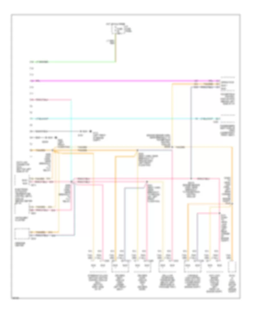
POWER DOOR LOCKS
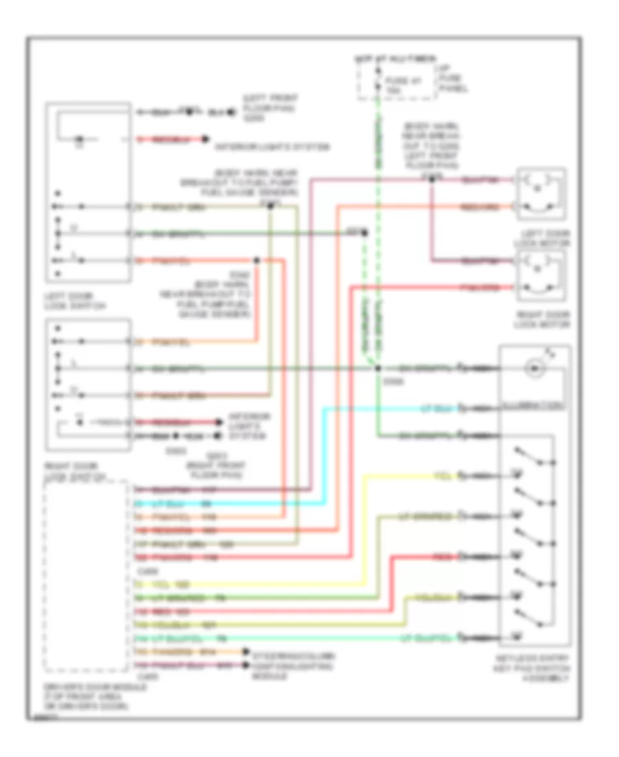
Power Door Lock Wiring Diagram for Lincoln Mark VIII 1997
 https://portal-diagnostov.com/license.html
Automotive Electricians Portal FZCO
Automotive Electricians Portal FZCO
https://portal-diagnostov.com/license.html
https://portal-diagnostov.com/license.html
Automotive Electricians Portal FZCO
Automotive Electricians Portal FZCOList of elements for Power Door Lock Wiring Diagram for Lincoln Mark VIII 1997:
- (body harn, near break- out to g200, left front floor pan) s339
- (body harn, near breakout to fuel pump/ fuel gauge sender)
- (left front floor pan) g200
- 1/2
- 3/4
- 5/6
- 7/8
- 9/0
- C455
- C456
- Driver's door module (top front area or driver's door)
- Fuse 41 10a
- G203 (right front floor pan)
- Hot at all times
- I/p fuse panel
- Illumination
- Interior lights system
- Keyless entry key pad switch assembly
- Left door lock motor
- Left door lock switch
- Nca
- Red
- Right door lock motor
- Right door lock switch
- S341
- S342 (body harn, near breakout to fuel pump/fuel gauge sender)
- S503
- S506
- S510
- S603
- Steering/column ignition/lighting module
POWER MIRRORS
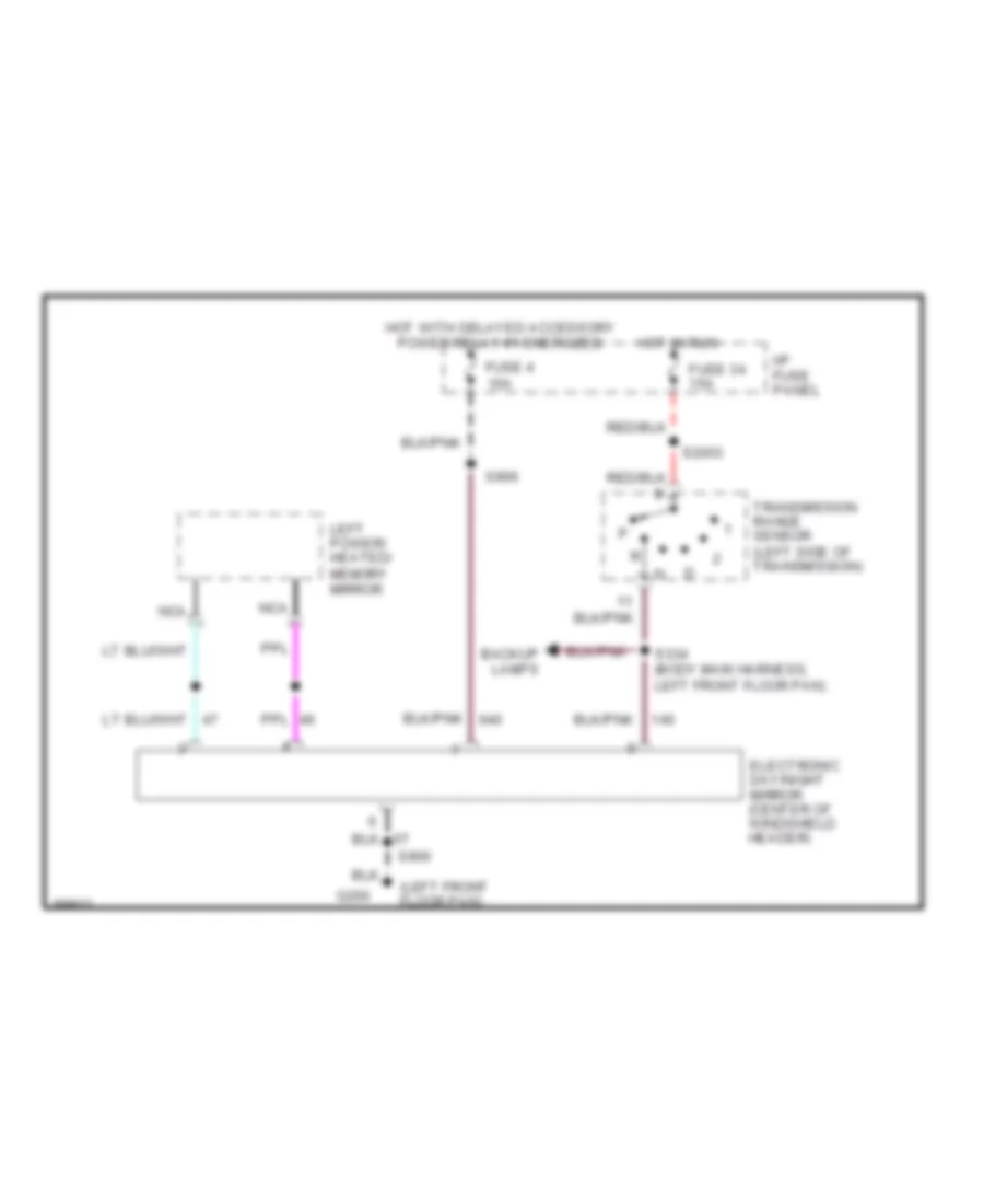
Electrochromic Mirror Wiring Diagram for Lincoln Mark VIII 1997
 https://portal-diagnostov.com/license.html
Automotive Electricians Portal FZCO
Automotive Electricians Portal FZCO
https://portal-diagnostov.com/license.html
https://portal-diagnostov.com/license.html
Automotive Electricians Portal FZCO
Automotive Electricians Portal FZCOList of elements for Electrochromic Mirror Wiring Diagram for Lincoln Mark VIII 1997:
- (left front floor pan)
- Backup lamps
- Electronic day/night mirror (center of windshield header)
- Fuse 34 15a
- Fuse 4 10a
- G200
- Hot in run
- Hot with delayed accessory power relay #1 energized
- I/p fuse panel
- Left power/ heated/ memory mirror
- Nca
- S2003
- S334 (body main harness, left front floor pan)
- S900
- S906
- Transmission range sensor (left side of transmission)
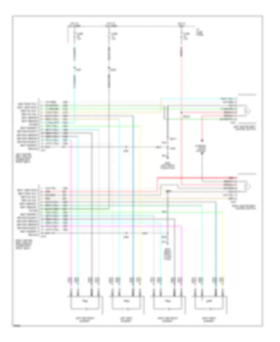
POWER SEATS
Heated Seats Wiring Diagram for Lincoln Mark VIII 1997
 https://portal-diagnostov.com/license.html
Automotive Electricians Portal FZCO
Automotive Electricians Portal FZCO
https://portal-diagnostov.com/license.html
https://portal-diagnostov.com/license.html
Automotive Electricians Portal FZCO
Automotive Electricians Portal FZCOList of elements for Heated Seats Wiring Diagram for Lincoln Mark VIII 1997:
- C340
- C341
- C371
- C374
- Fuse 10a
- Fuse 15a
- G200 (left front floor plan)
- G203 (right front floor plan)
- Ground
- Hot at all times
- Hot in run
- I/p fuse panel
- Interior lights system
- Left heated seat control switch
- Left heated seat module (under left front seat)
- Left seat element
- Left seatback element
- Nca
- Power
- Red
- Right heated seat control switch
- Right heated seat module (under right front seat)
- Right seat element
- Right seatback element
- S2015
- S2017
- S209
- S300
- S302
- S357
- S359
- S361
- S362
- Seat back only
- Seat element
- Seat sensor
- Seat sensor +
- Seat sensor -
- Seat, seat back
- Seatbck elemnt
- Seatbck sensor
- Temp adj sig +
- Temp adj sig -
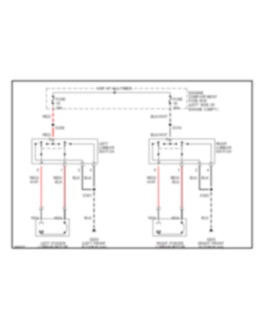
Lumbar Wiring Diagram for Lincoln Mark VIII 1997
 https://portal-diagnostov.com/license.html
Automotive Electricians Portal FZCO
Automotive Electricians Portal FZCO
https://portal-diagnostov.com/license.html
https://portal-diagnostov.com/license.html
Automotive Electricians Portal FZCO
Automotive Electricians Portal FZCOList of elements for Lumbar Wiring Diagram for Lincoln Mark VIII 1997:
- Eingine compartment fuse box (left side of engine compt)
- Fuse 30a
- G200 (left front floor plan)
- G203 (right front floor plan)
- Hot at all times
- Left lumbar switch
- Left power lumbar motor
- Nca
- Red
- Right lumbar switch
- Right power lumbar motor
- S310
- S358
- S361
- S362
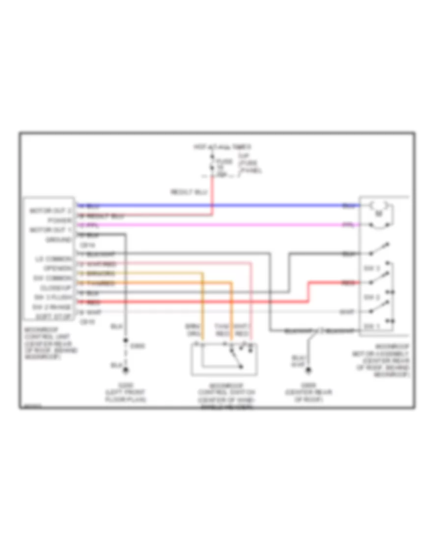
POWER TOP/SUNROOF
Power Top/Sunroof Wiring Diagrams for Lincoln Mark VIII 1997
 https://portal-diagnostov.com/license.html
Automotive Electricians Portal FZCO
Automotive Electricians Portal FZCO
https://portal-diagnostov.com/license.html
https://portal-diagnostov.com/license.html
Automotive Electricians Portal FZCO
Automotive Electricians Portal FZCOList of elements for Power Top/Sunroof Wiring Diagrams for Lincoln Mark VIII 1997:
- (center of wind- shield header)
- C914
- C915
- Close/up
- Fuse 20a
- G200 (left front floor plan)
- G909 (center rear of roof)
- Ground
- Hot at all times
- I/p fuse panel
- Ls common
- Moonroof control switch
- Moonroof control unit (center rear of roof, behind moonroof)
- Moonroof motor assembly (center rear of roof, behind moonroof)
- Motor out 1
- Motor out 2
- Open/dn
- Power
- Red
- S900
- Soft stop
- Sw 1
- Sw 2
- Sw 2 range
- Sw 3
- Sw 3 flush
- Sw common
- Tan/ red
- Tan/red
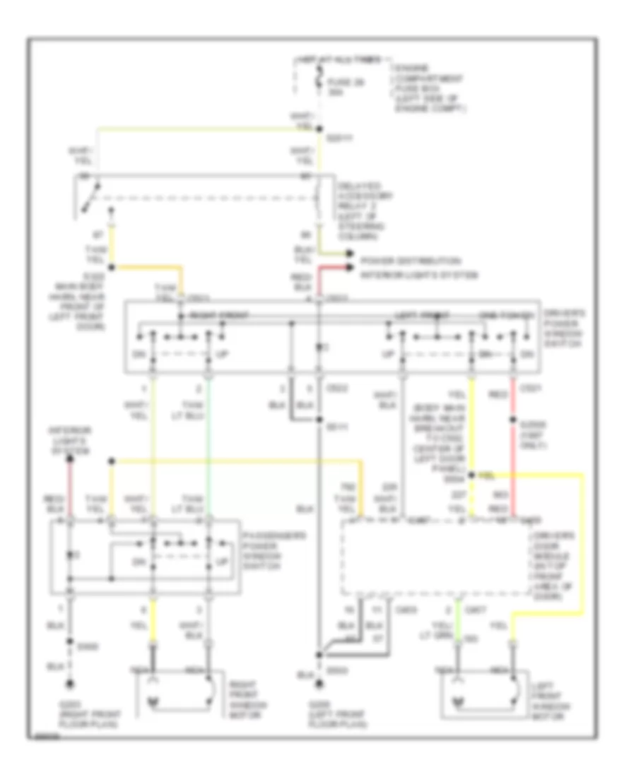
POWER WINDOWS
Power Window Wiring Diagram for Lincoln Mark VIII 1997
 https://portal-diagnostov.com/license.html
Automotive Electricians Portal FZCO
Automotive Electricians Portal FZCO
https://portal-diagnostov.com/license.html
https://portal-diagnostov.com/license.html
Automotive Electricians Portal FZCO
Automotive Electricians Portal FZCOList of elements for Power Window Wiring Diagram for Lincoln Mark VIII 1997:
- (body main harn, near breakout to c502, center of left door panel) s504
- C456
- C457
- C521
- C522
- Delayed accessory relay 2 (left of steering column)
- Driver's door module (in top front area of door)
- Driver's one tch dn
- Engine compartment fuse box (left side of engine compt)
- Fuse 28 30a
- G200 (left front floor plan)
- G203 (right front floor plan)
- Hot at all times
- Interior lights system
- Left front
- Left front window motor
- Nca
- Passenger's power window switch
- Power distribution
- Power window switch
- Red
- Right front
- Right front window motor
- S2011
- S2505 (1997 only)
- S322 main body harn, near front of left front door)
- S500
- S511
- S600
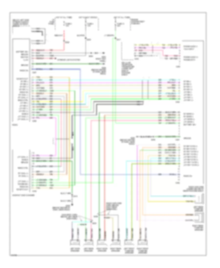
RADIO
JBL System for Lincoln Mark VIII 1997
 https://portal-diagnostov.com/license.html
Automotive Electricians Portal FZCO
Automotive Electricians Portal FZCO
https://portal-diagnostov.com/license.html
https://portal-diagnostov.com/license.html
Automotive Electricians Portal FZCO
Automotive Electricians Portal FZCOList of elements for JBL System for Lincoln Mark VIII 1997:
- (below left side of rear window) hidden antenna module
- (main body harn, behind left rear side panel)
- (radio amplifier harn, behind right rear side panel)
- Battery (b+)
- C257
- C258
- C402
- C445
- C450
- C451
- C452
- C453
- Cd data out
- Cellular telephone transceiver (under left side of package shelf)
- Compact disk changer
- Engine compartment fuse box
- Fuse 10 20a
- Fuse 2 10a
- Fuse 4 10a
- G203 (right kick panel)
- G206 (behind center of dash, near radio)
- Ground
- Hot at all times
- Hot in accy or run
- I/p fuse panel
- Ignition
- Illum
- Interior lights system
- Left door speaker
- Left front tweeter speaker
- Left rear speaker
- Left rear tweeter speaker
- Lft chnl (+)
- Lft chnl (-)
- Lft frt (+)
- Lft frt (-)
- Lft frt twtr (+)
- Lft frt twtr (-)
- Lft rr (+)
- Lft rr (-)
- Lft rr twtr (+)
- Lft rr twtr (-)
- Lft spkr (+)
- Lft spkr (-)
- Nca
- Phone audio (+)
- Phone audio (-)
- Phone data
- Pnk
- Power (b+)
- Radio
- Radio amplifier (under center of rear package shelf)
- Radio ctrl
- Radio on
- Right door speaker
- Right front tweeter speaker
- Right rear speaker
- Right rear tweeter speaker
- Rt chnl (+)
- Rt chnl (-)
- Rt frt (+)
- Rt frt (-)
- Rt frt twtr (+)
- Rt frt twtr (-)
- Rt rr (+)
- Rt rr (-)
- Rt rr twtr (+)
- Rt rr twtr (-)
- Rt spkr (+)
- Rt spkr (-)
- S208
- S226
- S233
- S345
- S346
- S406
- S410
- S411
- S429
- S430
- Shield
- Talk input
- Tan
Premium Sound Radio Wiring Diagram for Lincoln Mark VIII 1997
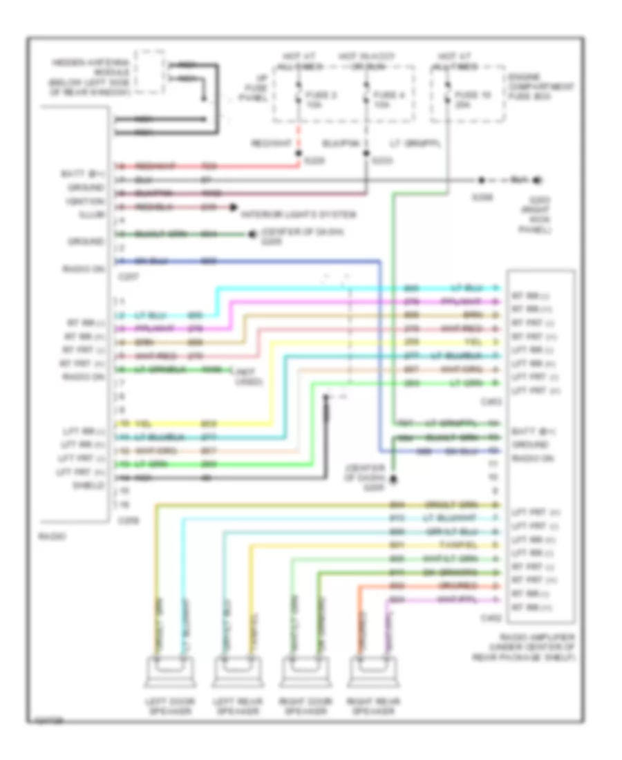 https://portal-diagnostov.com/license.html
Automotive Electricians Portal FZCO
Automotive Electricians Portal FZCO
https://portal-diagnostov.com/license.html
https://portal-diagnostov.com/license.html
Automotive Electricians Portal FZCO
Automotive Electricians Portal FZCOList of elements for Premium Sound Radio Wiring Diagram for Lincoln Mark VIII 1997:
- (center of dash) g205
- (not used)
- Batt (b+)
- C257
- C258
- C452
- C453
- Engine compartment fuse box
- Fuse 10 20a
- Fuse 2 10a
- Fuse 4 10a
- G203 (right kick panel)
- Ground
- Hidden antenna module (below left side of rear window)
- Hot at all times
- Hot in accy or run
- I/p fuse panel
- Ignition
- Illum
- Interior lights system
- Left door speaker
- Left rear speaker
- Lft frt (+)
- Lft frt (-)
- Lft rr (+)
- Lft rr (-)
- Nca
- Radio
- Radio amplifier (under center of rear package shelf)
- Radio on
- Right door speaker
- Right rear speaker
- Rt frt (+)
- Rt frt (-)
- Rt rr (+)
- Rt rr (-)
- S208
- S226
- S233
- Shield
SHIFT INTERLOCKS
Shift Interlock Wiring Diagram for Lincoln Mark VIII 1997
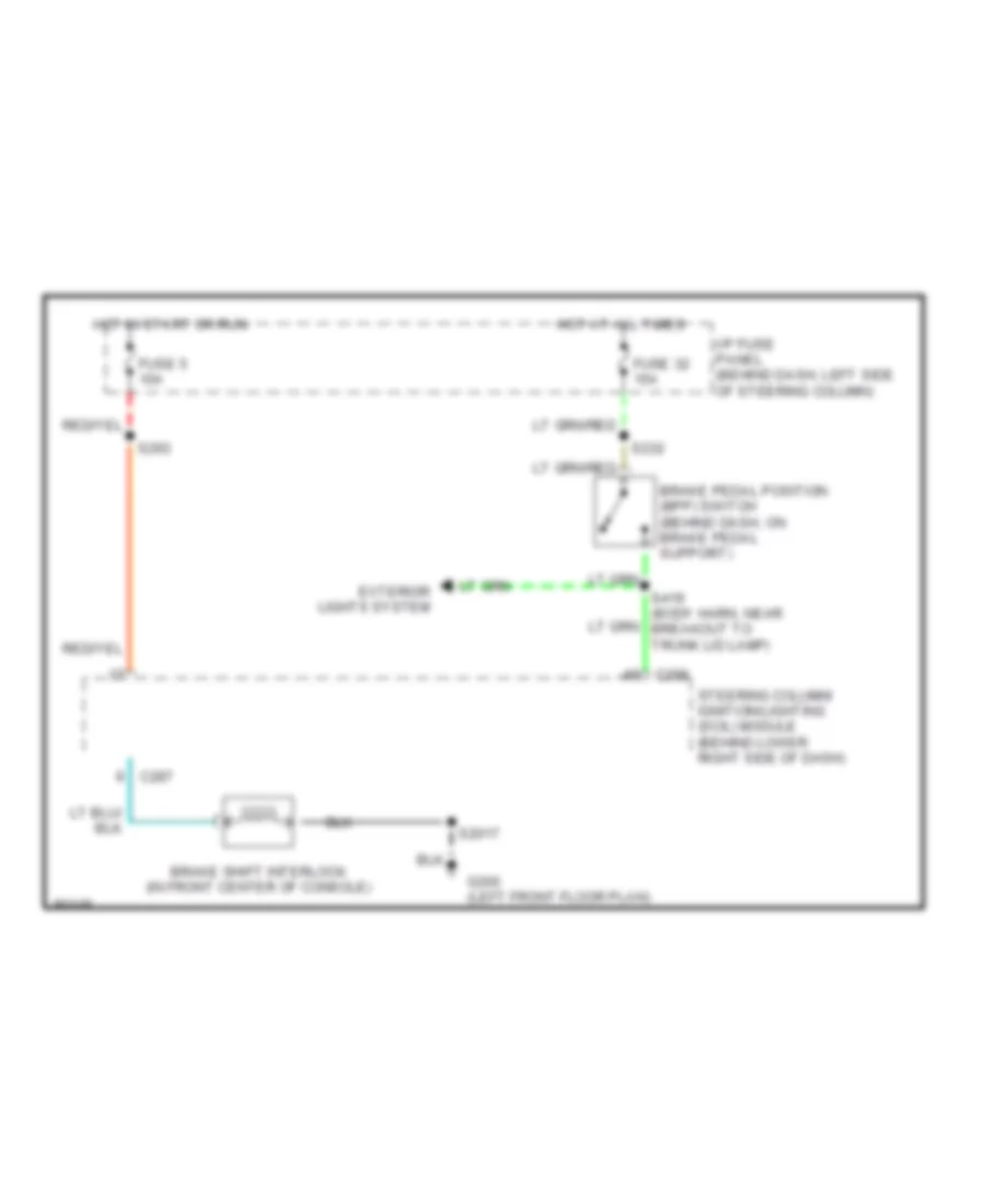 https://portal-diagnostov.com/license.html
Automotive Electricians Portal FZCO
Automotive Electricians Portal FZCO
https://portal-diagnostov.com/license.html
https://portal-diagnostov.com/license.html
Automotive Electricians Portal FZCO
Automotive Electricians Portal FZCOList of elements for Shift Interlock Wiring Diagram for Lincoln Mark VIII 1997:
- Brake pedal position (bpp) switch (behind dash, on brake pedal support)
- Brake shift interlock (in front center of console)
- C287
- C288
- Exterior lights system
- Fuse 32 15a
- Fuse 5 10a
- G200 (left front floor plan)
- Hot at all times
- Hot in start or run
- I/p fuse panel (behind dash, left side of steering column)
- S2017
- S232
- S293
- S419 (body harn, near breakout to trunk lid lamp)
- Steering column/ ignition/lighting (scil) module (behind lower right side of dash)
STARTING/CHARGING
Charging Wiring Diagram for Lincoln Mark VIII 1997
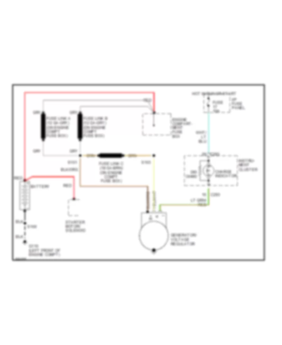 https://portal-diagnostov.com/license.html
Automotive Electricians Portal FZCO
Automotive Electricians Portal FZCO
https://portal-diagnostov.com/license.html
https://portal-diagnostov.com/license.html
Automotive Electricians Portal FZCO
Automotive Electricians Portal FZCOList of elements for Charging Wiring Diagram for Lincoln Mark VIII 1997:
- Battery
- C293
- Charge indicator
- Engine compart- ment fuse box
- Fuse 10a
- G110 (left front of engine compt)
- Generator/ voltage regulator
- Hot in run or start
- I/p fuse panel
- Instru- ment cluster
- Ohms
- Red
- S100
- S101
- S103
- Starter motor/ solenoid
Starting Wiring Diagram for Lincoln Mark VIII 1997
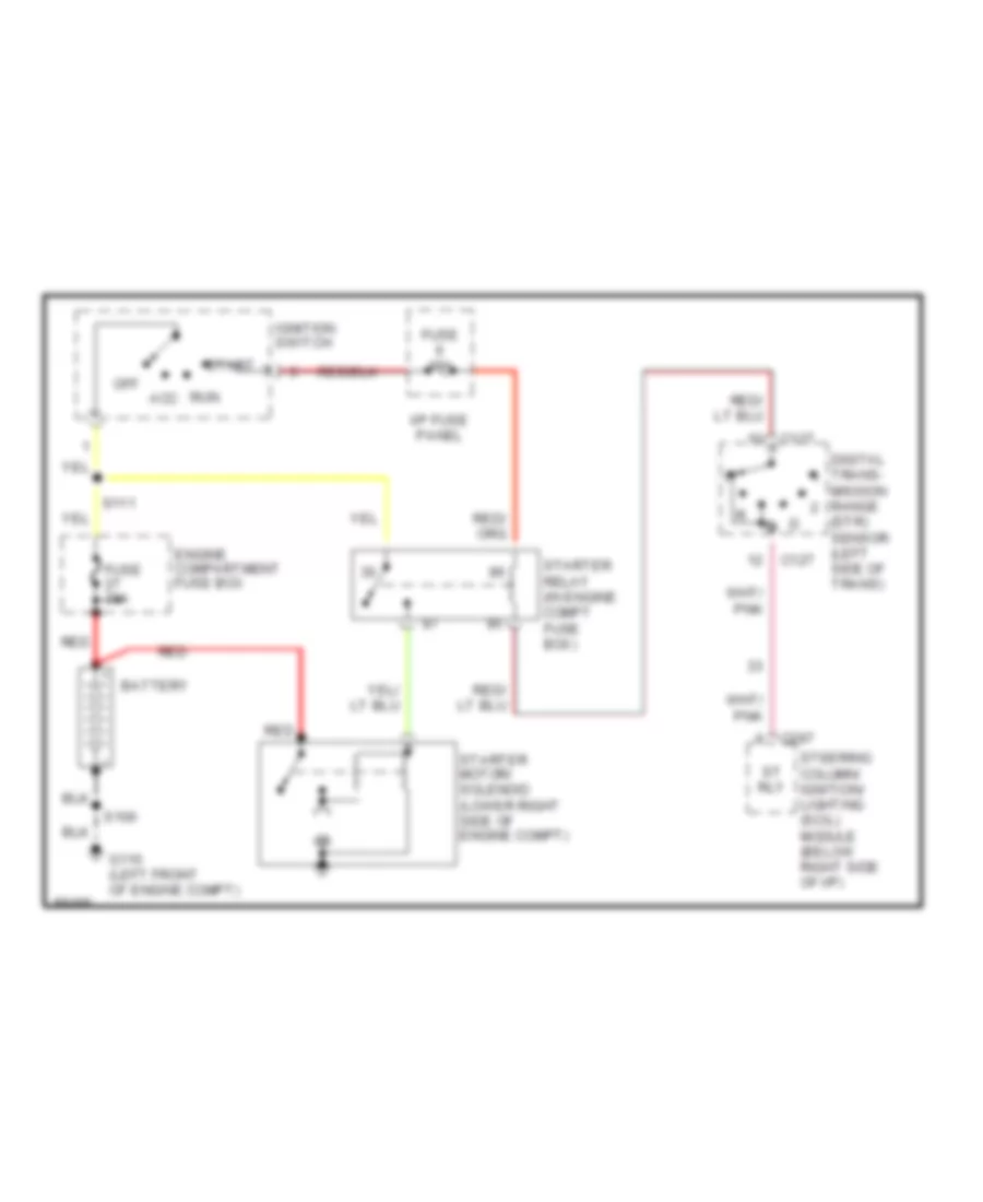 https://portal-diagnostov.com/license.html
Automotive Electricians Portal FZCO
Automotive Electricians Portal FZCO
https://portal-diagnostov.com/license.html
https://portal-diagnostov.com/license.html
Automotive Electricians Portal FZCO
Automotive Electricians Portal FZCOList of elements for Starting Wiring Diagram for Lincoln Mark VIII 1997:
- Acc
- Battery
- C127
- C287
- Digital trans- mission range (dtr) sensor (left side of trans)
- Engine compartment fuse box
- Fuse 10a
- Fuse 30a
- G110 (left front of engine compt)
- I/p fuse panel
- Ignition switch
- Off
- Red
- Run
- S100
- S111
- St rly
- Start
- Starter motor/ solenoid (lower right side of engine compt)
- Starter relay (in engine compt fuse box)
- Steering column/ ignition/ lighting (scil) module (below right side of i/p)
SUPPLEMENTAL RESTRAINTS
Supplemental Restraint Wiring Diagram for Lincoln Mark VIII 1997
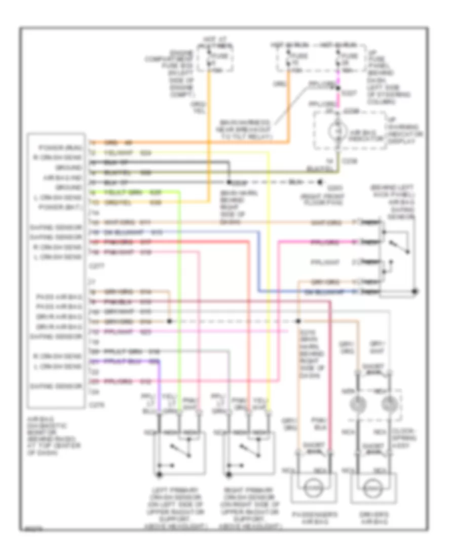 https://portal-diagnostov.com/license.html
Automotive Electricians Portal FZCO
Automotive Electricians Portal FZCO
https://portal-diagnostov.com/license.html
https://portal-diagnostov.com/license.html
Automotive Electricians Portal FZCO
Automotive Electricians Portal FZCOList of elements for Supplemental Restraint Wiring Diagram for Lincoln Mark VIII 1997:
- (behind left kick panel) air bag safing sensor
- (main harn, behind right side of dash)
- (main harness, near breakout to tilt relay)
- (right front floor pan)
- Air bag diagnostic monitor (behind radio, at top center of dash)
- Air bag ind
- Air bag indicator
- All times
- C238
- C276
- C277
- Clock- nca
- Driver's air bag
- Drvr air bag
- Engine compartment fuse box (in left side of engine compt)
- Fuse 10a
- G203
- Ground
- Hot at
- Hot in run
- I/p fuse panel (behind dash, left side of steering column)
- I/p warning indicator display
- L crash sens
- Left primary crash sensor (on left side of upper radiator support, above headlight)
- Nca
- Pass air bag
- Passenger's air bag
- Power (bat)
- Power (run)
- R crash sens
- Right primary crash sensor (on right side of upper radiator support, above headlight)
- S209
- S210 (main harn, behind right side of dash)
- S227
- Safing sensor
- Short bar
- Spring assy
TRANSMISSION
Transmission Wiring Diagram for Lincoln Mark VIII 1997
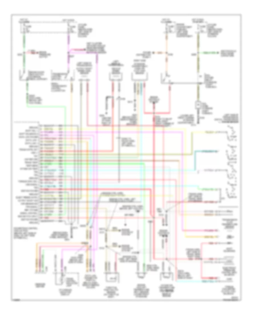 https://portal-diagnostov.com/license.html
Automotive Electricians Portal FZCO
Automotive Electricians Portal FZCO
https://portal-diagnostov.com/license.html
https://portal-diagnostov.com/license.html
Automotive Electricians Portal FZCO
Automotive Electricians Portal FZCOList of elements for Transmission Wiring Diagram for Lincoln Mark VIII 1997:
- (behind dash, near steering wheel bracket)
- (behind left side of dash, on left side of firewall)
- (center of dash) right of radio)
- (dash to hdlmp harn, left side of firewall)
- (eng ctrl harn, rear of trans)
- (engine ctrl harn, behind left kick pnl)
- (engine ctrl harn, in breakout to pcm)
- (engine ctrl harn, left corner of eng compt)
- (engine ctrl harn, left rear side of engine)
- (left rear of transmission)
- (left side of transmission)
- (left side of transmission) digital transmission range sensor
- (lower left front corner of engine compartment)
- (main harn, behind left kick panel)
- (right side
- (trans harn, left side of trans, near dtr sensor)
- (trans harn, left side of trans, near right h20s) s125
- 4r70w transmission
- Boo switch input
- Brake on/off (boo) switch (on brake pedal support)
- Brake pressure switch
- C238
- C246
- Data link +
- Data link -
- Data link connector (partial) (below dash, near steering column)
- Data link power
- Elect press cntrl
- Electronic pressure control (epc) solenoid
- Engine compartment fuse box (left side of engine compartment)
- Engine controls system
- Engine coolant temperature (ect) sensor (lower front of engine)
- Fuse 10a
- Fuse 15a
- G110
- G204
- G204 (behind dash, near steering wheel bracket)
- G206
- Ground
- Hot at all times
- Hot in run
- Hot in run or start
- I/p fuse panel (behind dash, left side of steering column)
- I/p warning indicator display
- Ignition coils, radio noise capacitors
- Ignition power
- Inst cluster, air susp module, rear defogger, steering wheel rotation sensor
- Intake air temp
- Intake air temperature (iat) sensor (top center rear of engine)
- Maf return
- Maf sensor sig
- Message center
- Of engine compartment) mass air flow (maf) sensor
- Output shaft sig
- Output shaft speed (oss) sensor
- Pcm diode (in engine compt fuse box)
- Pcm power relay (in engine compt fuse box)
- Power distribution (fuse 1)
- Powertrain control module (pcm)
- Prndl/ transmission control illumination
- R p
- Red
- Ref votage
- S123
- S124 (dash to hdlmp harn, right red front corner of engine compt)
- S129
- S132
- S133
- S137
- S168
- S169
- S2018 (main harn, below left side of dash)
- S2019
- S2020
- S213
- S232
- S252
- S284
- S295
- S296 (main harn, behind left side of dash)
- S299
- Shift sol 1
- Shift solenoid 2
- Shift solenoids
- Signal control
- Ss1
- Ss2
- Temp sens
- Throttle position (tp) sensor (on throttle body)
- Torque conv sol
- Torque converter clutch (tcc) solenoid
- Tps signal
- Tr1
- Tr2
- Tr3
- Tr4
- Trans cntrl sw
- Trans control indicator lamp
- Trans temp
- Transmission control switch
- Transmission fluid temperature sensor
- Vehicle speed sensor
- Vss (-)
- Vss signal
TRUNK, TAILGATE, FUEL DOOR
Trunk & Fuel Door Release Wiring Diagram for Lincoln Mark VIII 1997
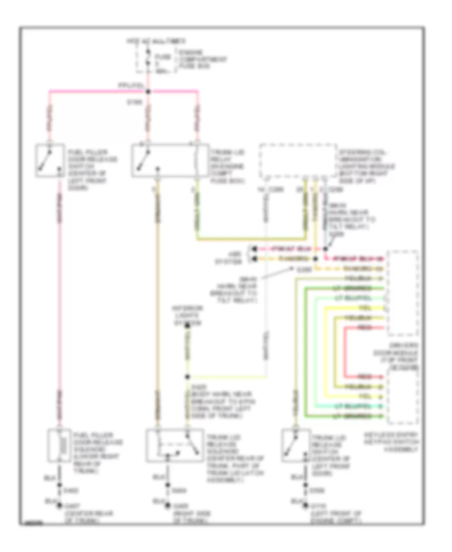 https://portal-diagnostov.com/license.html
Automotive Electricians Portal FZCO
Automotive Electricians Portal FZCO
https://portal-diagnostov.com/license.html
https://portal-diagnostov.com/license.html
Automotive Electricians Portal FZCO
Automotive Electricians Portal FZCOList of elements for Trunk & Fuel Door Release Wiring Diagram for Lincoln Mark VIII 1997:
- (main harn, near breakout to tilt relay)
- (main harn, near breakout to tilt relay) s296
- Abs system
- C286
- C288
- Driver's door module (top front of door)
- Engine compartment fuse box
- Fuel filler door release solenoid (lower right rear of trunk)
- Fuel filler door release switch (center of left front door)
- Fuse 10a
- G110 (left front of engine compt)
- G405 (right side of trunk)
- G407 (center rear of trunk)
- Hot at all times
- Interior lights system
- Keyless entry keypad switch assembly
- Red
- S166
- S295
- S402
- S404
- S425 (body harn, near breakout to 8 pin conn, front left side of trunk)
- S508
- Steering col- umn/ignition lighting module (bottom right side of i/p)
- Trunk lid relay (in engine compt fuse box)
- Trunk lid release solenoid (center rear of trunk, part of trunk lid latch assembly)
- Trunk lid release switch (center of left front door)
WARNING SYSTEMS
Warning System Wiring Diagrams for Lincoln Mark VIII 1997
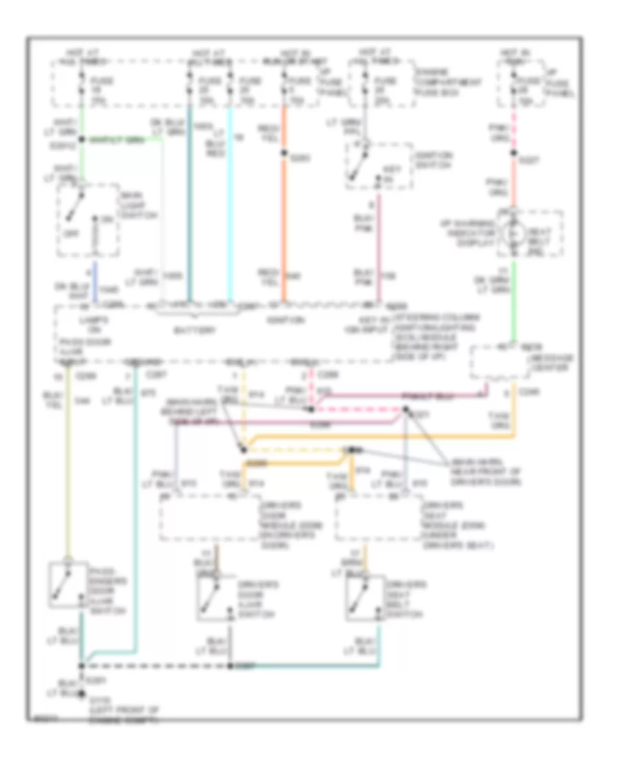 https://portal-diagnostov.com/license.html
Automotive Electricians Portal FZCO
Automotive Electricians Portal FZCO
https://portal-diagnostov.com/license.html
https://portal-diagnostov.com/license.html
Automotive Electricians Portal FZCO
Automotive Electricians Portal FZCOList of elements for Warning System Wiring Diagrams for Lincoln Mark VIII 1997:
- (main harn, behind left side of i/p)
- (main harn, near front of driver's door)
- Battery
- Bus (+)
- Bus (-)
- C238
- C246
- C286
- C287
- C288
- Driver's door ajar switch
- Driver's door module (ddm) (in driver's door)
- Driver's seat belt switch
- Driver's seat module (dsm) (under driver's seat)
- Engine compartment fuse box
- Fuse 10a
- Fuse 15a
- Fuse 20a
- G110 (left front of engine compt)
- Ground
- Hot at all times
- Hot in run
- Hot in run or start
- I/p fuse panel
- I/p warning indicator display
- Ignition
- Ignition switch
- Key in
- Lamps on
- Main light switch
- Message center
- Off
- Pass door ajar input
- Pass- enger's door ajar switch
- S2012
- S227
- S293
- S295
- S296
- S307
- S321
- S338
- Seat belt ind
- Steering column/ key in ignition/lighting ign input (scil) module (behind right side of i/p)
WIPER/WASHER
Wiper/Washer Wiring Diagram for Lincoln Mark VIII 1997
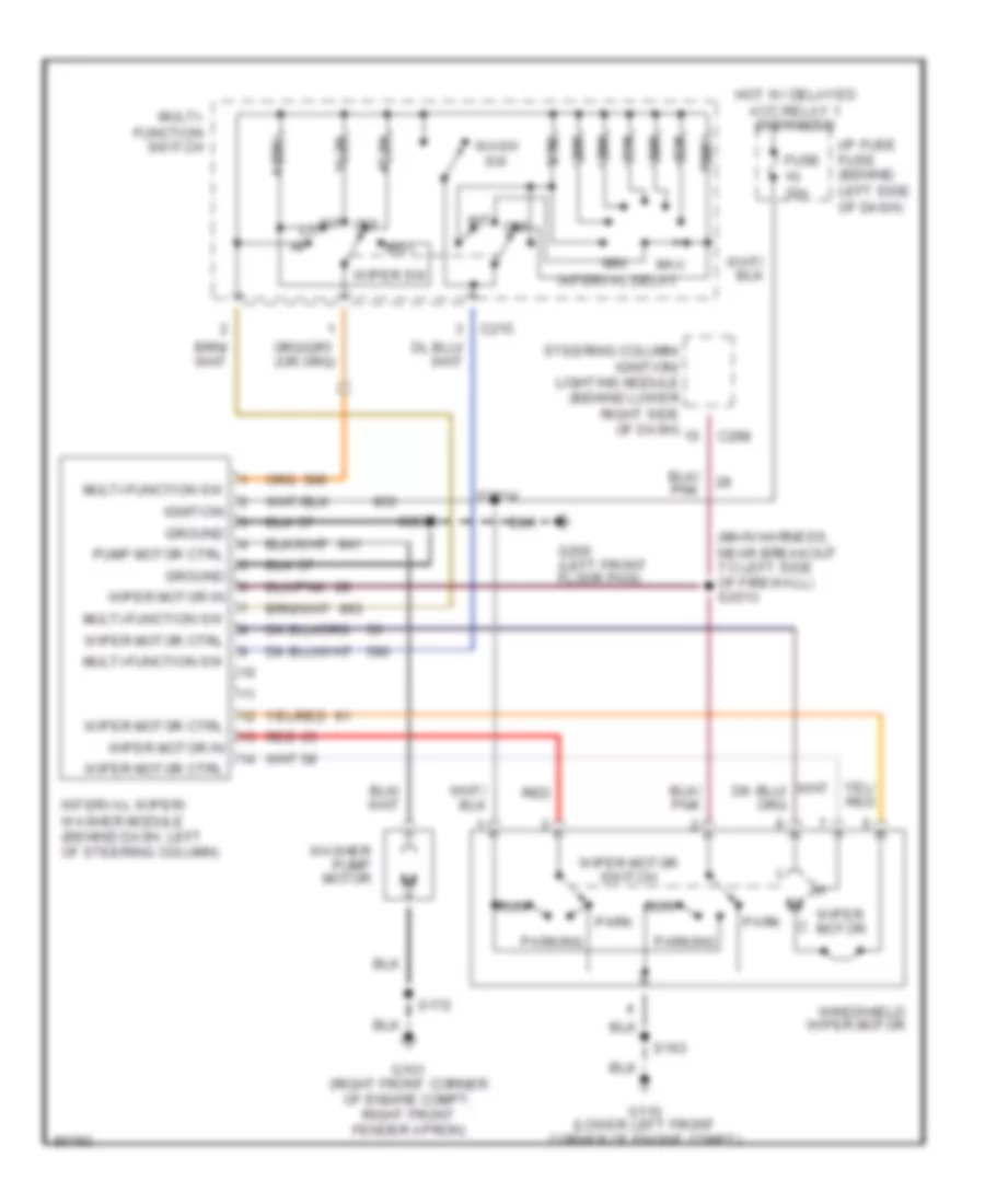 https://portal-diagnostov.com/license.html
Automotive Electricians Portal FZCO
Automotive Electricians Portal FZCO
https://portal-diagnostov.com/license.html
https://portal-diagnostov.com/license.html
Automotive Electricians Portal FZCO
Automotive Electricians Portal FZCOList of elements for Wiper/Washer Wiring Diagram for Lincoln Mark VIII 1997:
- (main harness, near breakout to left side of firewall) s2013
- 100k
- 11.2k
- 20k
- 3.3k
- 36k
- 4.08k
- 47.5k
- 51k
- 68k
- 82k
- C215
- C288
- Fuse 30a
- G101 (right front corner of engine compt, right front fender apron)
- G110 (lower left front corner of engine compt)
- G200 (left front floor pan)
- Ground
- Hot w/ delayed acc relay 1 energized
- I/p fuse fuse (behind left side of dash)
- Ignition
- Int
- Interval delay
- Interval wiper/ washer module (behind dash, left of steering column)
- Max
- Min
- Mist
- Multi- function switch
- Multi-function sw
- Off
- Park
- Parking
- Pump motor ctrl
- Red
- Run
- S163
- S172
- S2005
- S2014
- Steering column/ ignition/ lighting module (behind lower right side of dash)
- Wash sw
- Washer pump motor
- Windshield wiper motor
- Wiper motor
- Wiper motor ctrl
- Wiper motor in
- Wiper motor switch
- Wiper sw

 Čeština
 Dansk
Dansk Deutsch
 Ελληνικά
 English
 English
 Español
 Suomi
Suomi Français
 Français
 עברית
עברית Hrvatski
 Magyar
 Italiano
 한국어
한국어 Nederlands
 Polski
 Português
 Português
 Română
 Русский
 Slovenčina
 Slovenščina
 Svenska
 Türkçe
 中文 (中国)
