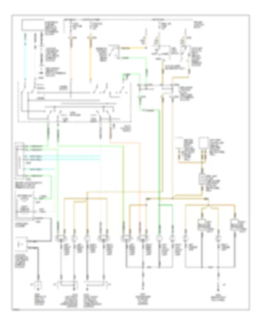
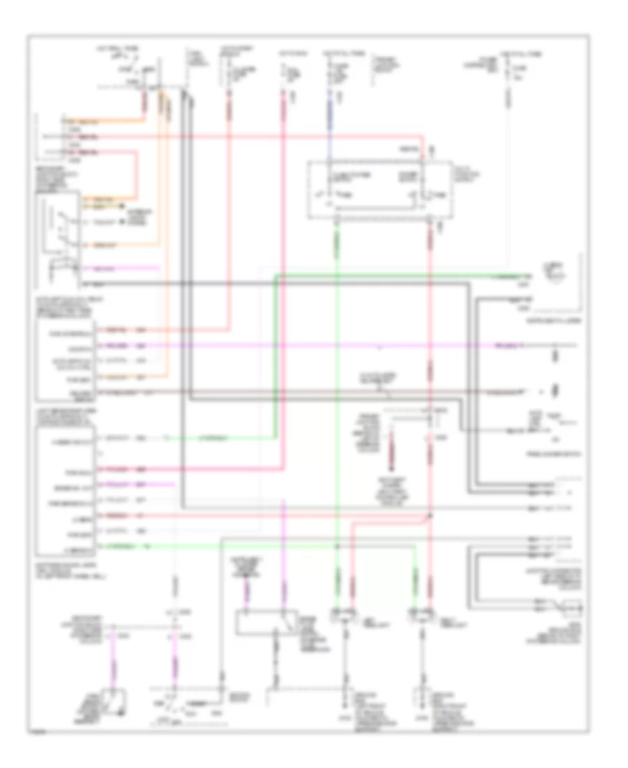
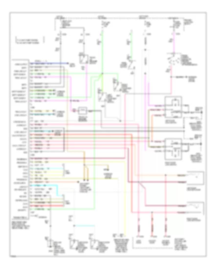
AIR CONDITIONING
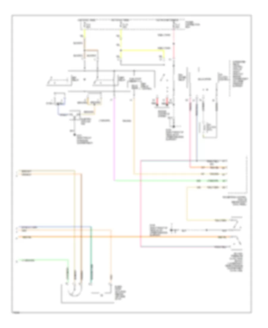
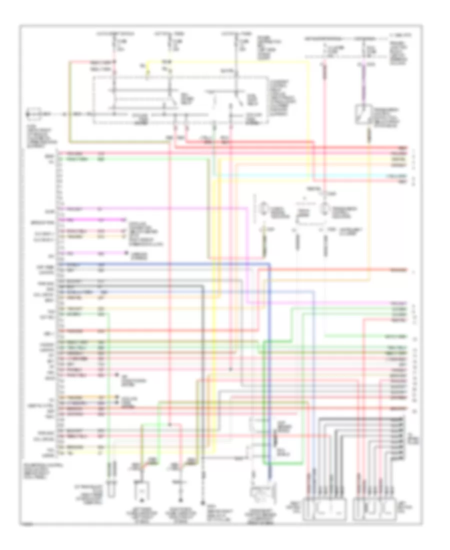
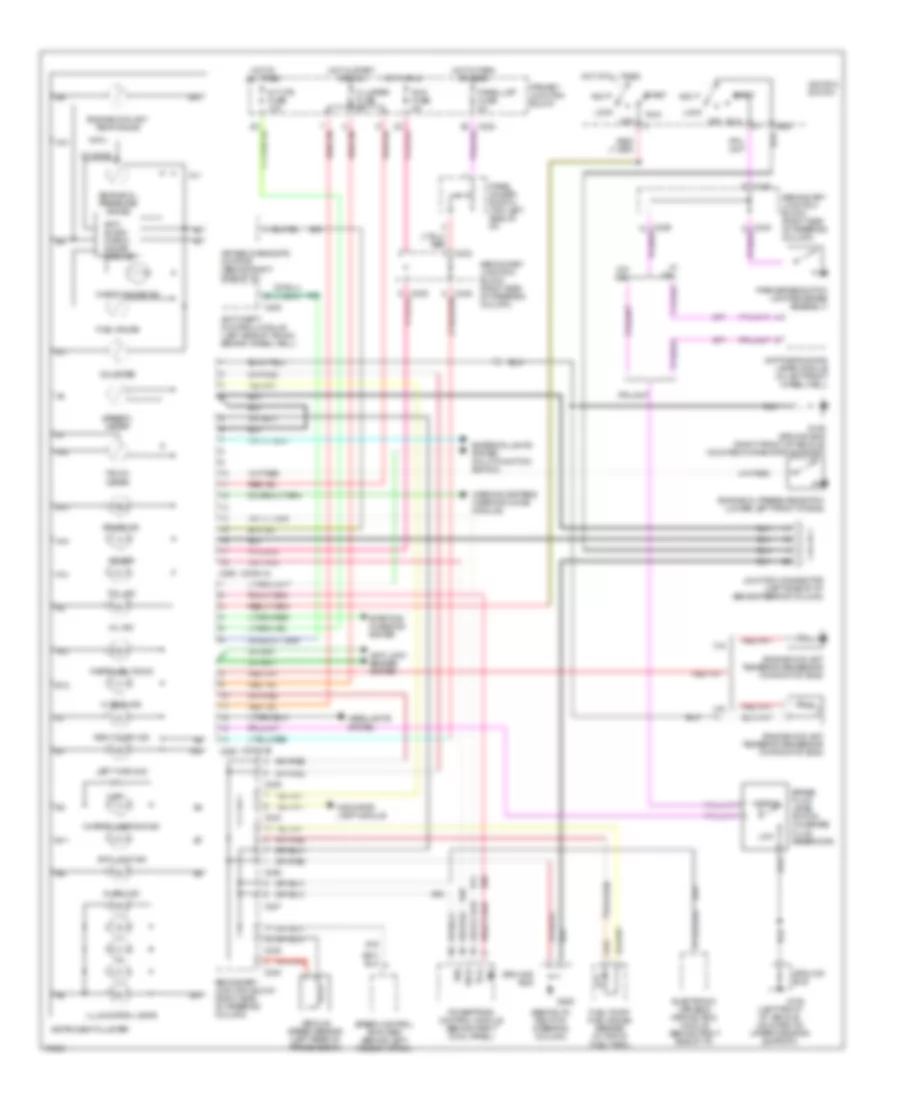
A/C Wiring Diagram, Auto A/C (1 of 2) for Mercury Cougar XR7 1996
 https://portal-diagnostov.com/license.html
Automotive Electricians Portal FZCO
Automotive Electricians Portal FZCO
https://portal-diagnostov.com/license.html
https://portal-diagnostov.com/license.html
Automotive Electricians Portal FZCO
Automotive Electricians Portal FZCO
List of elements for A/C Wiring Diagram, Auto A/C (1 of 2) for Mercury Cougar XR7 1996:
- 2 std fuse 5a
- 30a
- A/c clutch cycling pressure switch (right rear of engine compartment on accumulator)
- A/c fuse 10a
- Acc
- Atc ambient temperature sensor (right front of vehicle, on lower radiator support)
- Blower in-line fuse holder (behind left side of i/p, taped to harness)
- Blower motor
- Blower motor speed controller (behind right side of i/p)
- C232
- C233
- C240
- C298
- Cold engine lockout switch (top right side of engine)
- Def
- Flr
- Flr/def
- G202 (behind i/p, right of steering column)
- G203 (behind right cowl panel)
- Hot at all times
- Hot in run
- Ignition switch
- In-car temperature sensor (behind top left side of i/p)
- Interior lights system
- Joint connec- tor 1
- Joint connector
- Lock
- Max
- Norm
- Off
- Off pan/flr
- Outside/ recirculate solenoid (behind right side of i/p)
- Pan/flr flr
- Panel
- Power distribution box
- Primary junction block
- Run
- Run fuse 5a
- Secondary junction block
- Semi-automatic temperature control module (center of i/p)
- Solid state
- Start
- Sunload sensor (behind right top of i/p)
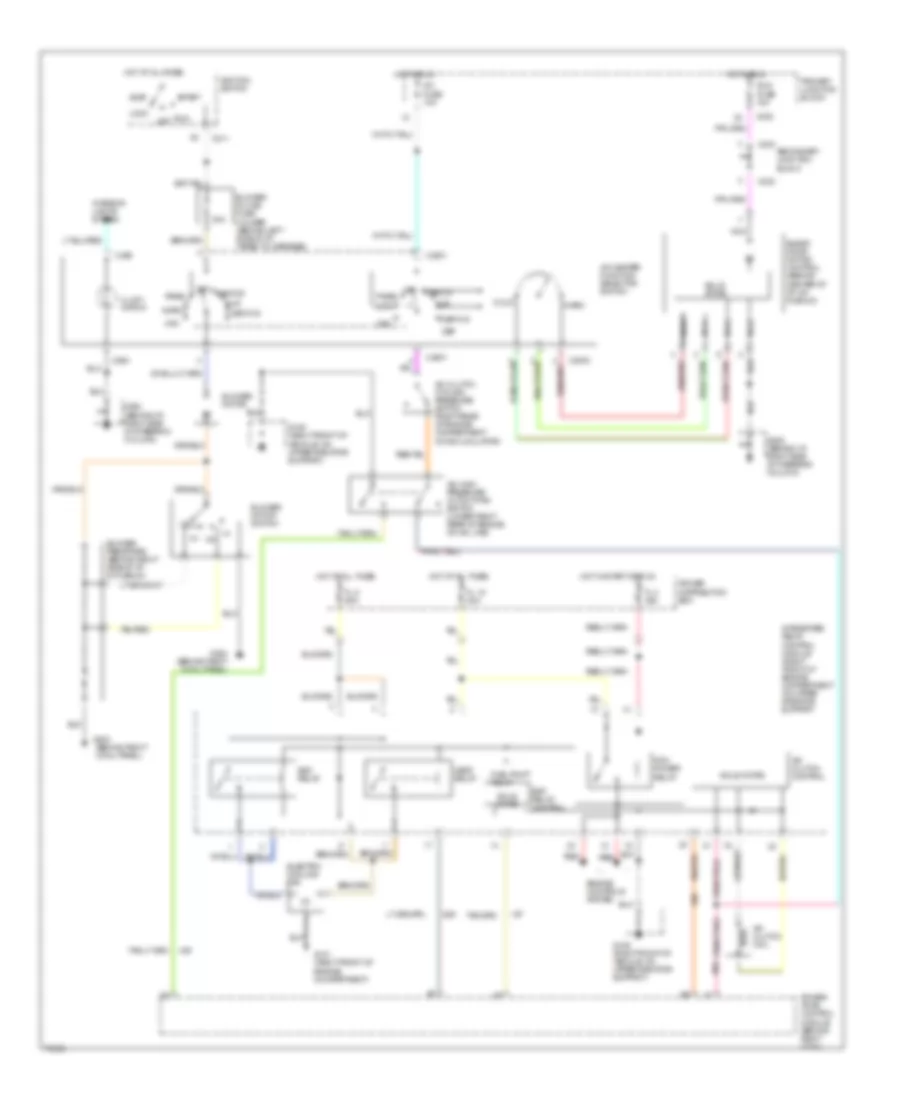
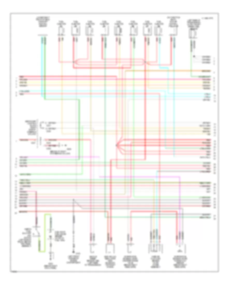
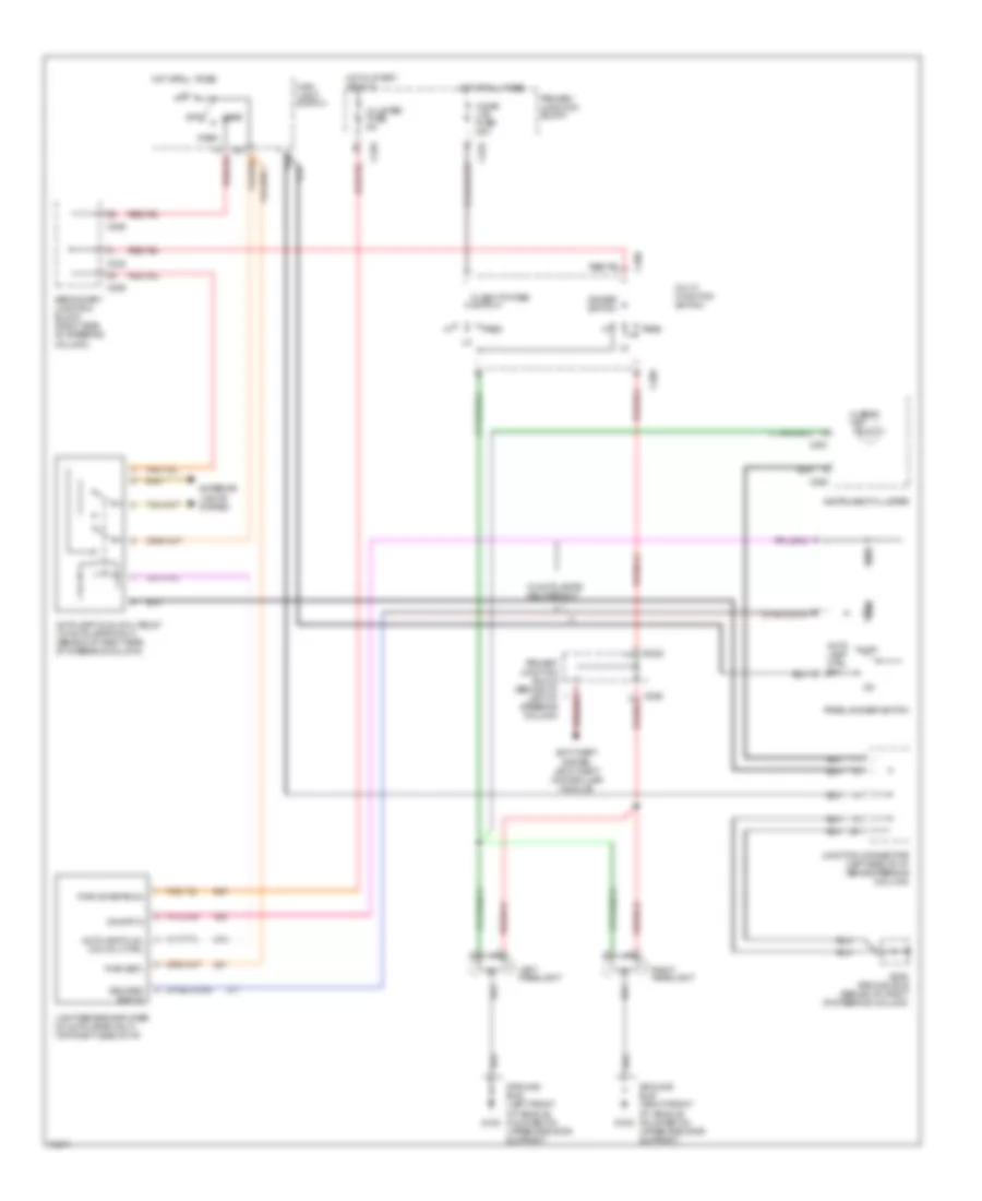
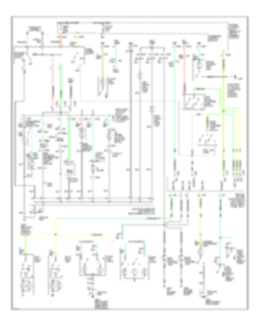
A/C Wiring Diagram, Auto A/C (2 of 2) for Mercury Cougar XR7 1996
 https://portal-diagnostov.com/license.html
Automotive Electricians Portal FZCO
Automotive Electricians Portal FZCO
https://portal-diagnostov.com/license.html
https://portal-diagnostov.com/license.html
Automotive Electricians Portal FZCO
Automotive Electricians Portal FZCOList of elements for A/C Wiring Diagram, Auto A/C (2 of 2) for Mercury Cougar XR7 1996:
- A/c clutch coil
- A/c clutch control
- A/c high pressure cutout/fan switch (lower right rear of engine compartment on a/c line)
- Blend door actuator (behind left side of i/p)
- Edf relay
- Edf relay control
- Electric cooling fan
- Engine controls system
- Fl 15 20a
- Fl 3 20a
- Fl 5 60a
- Fuel pump relay
- G101 (right front of engine compartment)
- G109 (right front of vehicle, on upper radiator support)
- Hedf relay
- Hot at all times
- Hot in start or run
- Integrated relay control module (right front of engine compartment on upper radiator support
- Pcm power relay
- Power distribution box
- Powertrain control module (behind right cowl panel)
- Red
- Solid state
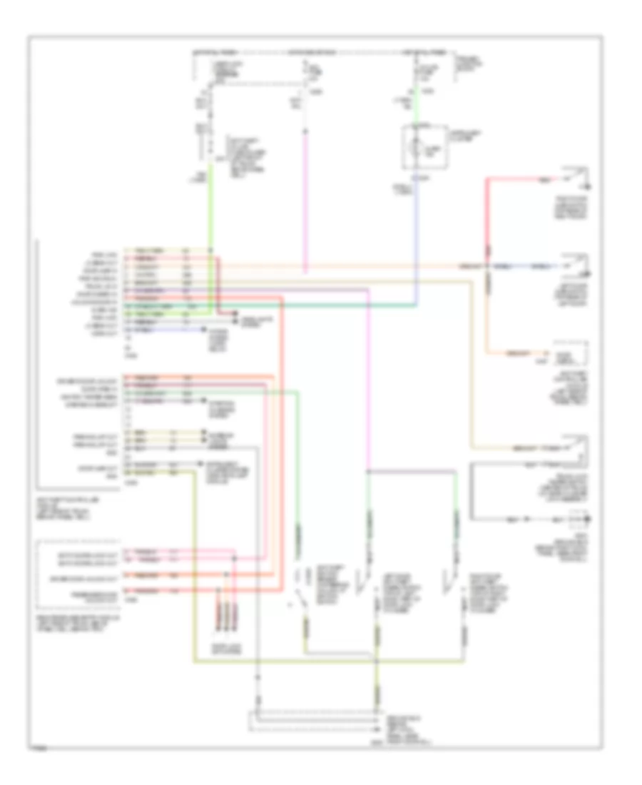
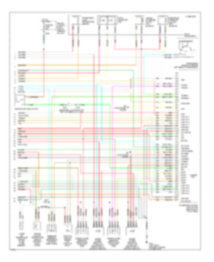
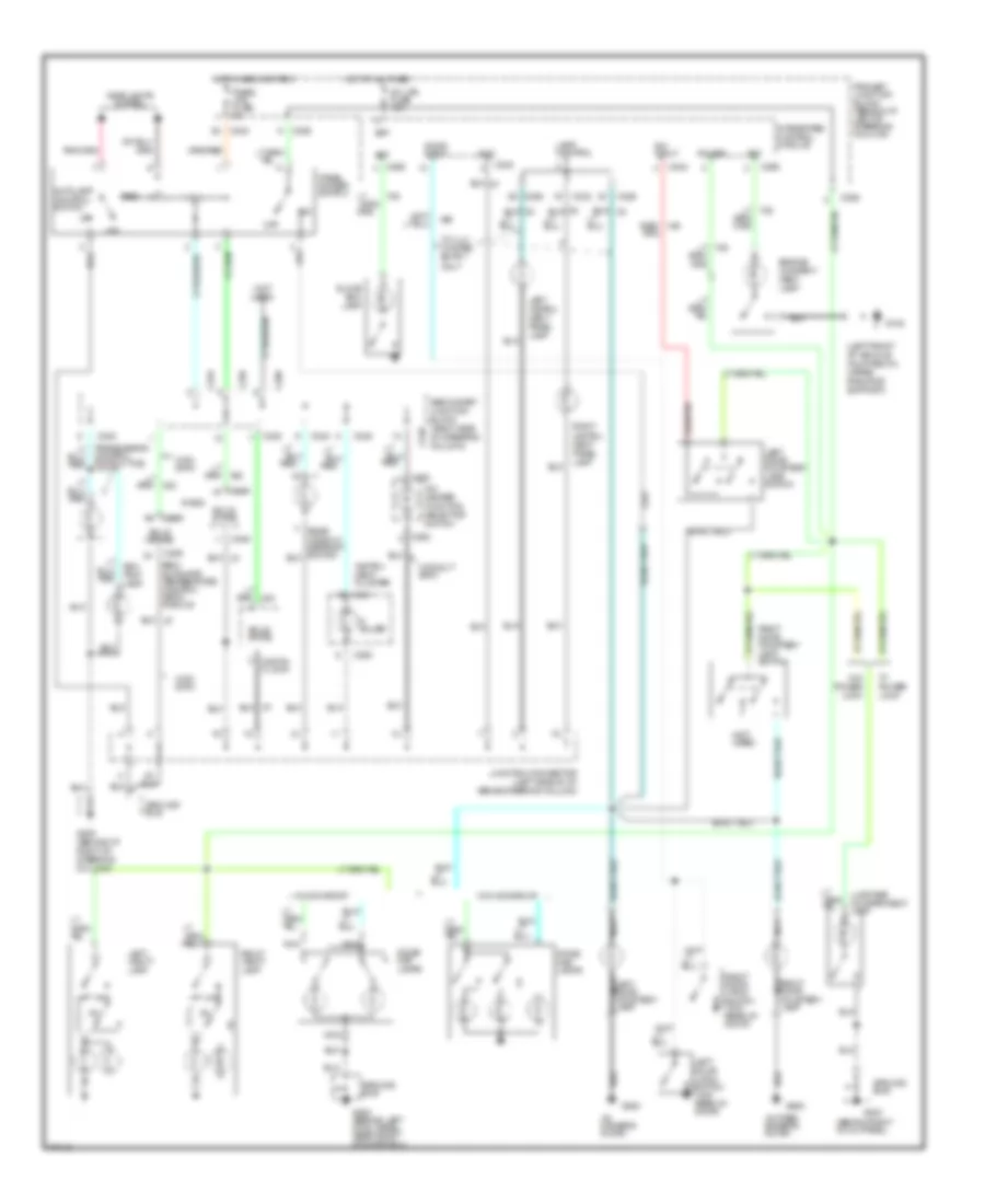
A/C Wiring Diagram, Manual A/C for Mercury Cougar XR7 1996
 https://portal-diagnostov.com/license.html
Automotive Electricians Portal FZCO
Automotive Electricians Portal FZCO
https://portal-diagnostov.com/license.html
https://portal-diagnostov.com/license.html
Automotive Electricians Portal FZCO
Automotive Electricians Portal FZCOList of elements for A/C Wiring Diagram, Manual A/C for Mercury Cougar XR7 1996:
- (behind right
- 30a
- A/c clutch coil
- A/c clutch control
- A/c clutch cycling pressure switch (right rear of engine compartment on accumulator)
- A/c fuse 10a
- A/c high pressure cutout/fan switch (lower right rear of engine on a/c line)
- A/c-heater function selector switch
- Acc
- Blend door motor control (behind center of i/p, on plenum)
- Blower in-line fuse holder (behind left side of i/p, taped to harness)
- Blower motor
- Blower motor switch
- Blower resistors (behind right side of i/p, in plenum)
- C2001
- C2003
- C211
- C232
- C233
- C263
- Cold
- Cowl panel)
- Def
- Def/flr
- Edf relay
- Edf relay control
- Electric cooling fan
- Engine controls system
- Fl 15 20a
- Fl 3 20a
- Fl 5 60a
- Flr
- Fuel pump relay
- G101 (right front of engine compartment)
- G109 (right front of vehicle, on upper radiator support)
- G202 (behind i/p, right side of steering column)
- G203
- G203 (behind right cowl panel)
- G205 (behind i/p, right side of steering column)
- Hedf relay
- Hot at all times
- Hot in run
- Hot in start or run
- Ignition switch
- Illumi- nation
- Integrated relay control module (right front of engine compartment on upper radiator support
- Interior lights system
- Lock
- Max
- Nca
- Norm
- Off
- Pan/flr
- Panel
- Pcm power relay
- Power distribution box
- Power- train control module (behind right cowl)
- Primary junction block
- Red
- Run
- Run fuse 10a
- Secondary junction block
- Solid state
- Start
- Warm
ANTI-LOCK BRAKES
Anti-lock Brake Wiring Diagrams for Mercury Cougar XR7 1996
 https://portal-diagnostov.com/license.html
Automotive Electricians Portal FZCO
Automotive Electricians Portal FZCO
https://portal-diagnostov.com/license.html
https://portal-diagnostov.com/license.html
Automotive Electricians Portal FZCO
Automotive Electricians Portal FZCOList of elements for Anti-lock Brake Wiring Diagrams for Mercury Cougar XR7 1996:
- (boo) switch
- (ground bus)
- (left front
- (left front corner of eng compt,
- (left front of
- (left front of
- (left front of eng compt)
- (left rear corner of eng compt)
- (left side of
- (left side of i/p)
- (on brake pedal
- (power distribution box)
- 10a
- 15a
- 20a
- 40a
- 87a
- Abs motor relay
- Abs relay
- Abs test conn
- Abs test conn input
- All times
- Anti/lock
- Anti/lock brake control module
- Anti/lock brake diode
- Anti/lock brake fluid level sw
- Anti/lock brake pedal travel sw
- Anti/lock ind
- Anti/lock power relay
- Assist
- Below battery)
- Block
- Box
- Brake
- Brake on/off
- Brake pump
- Brake sensor
- Brake sw input
- C226
- C232
- C251
- Cluster
- Compartment)
- Corner of
- Distribution
- Eng compt)
- Engine
- Engine compt)
- Fluid level sw input
- Fuse
- G100
- G108
- Ground
- Ground bus
- Haz
- Hot at
- Hot at all times
- Hot in run
- Indicator
- Inlet
- Instru/
- Junction
- Keep alive power
- L fnt brake sensor
- L fnt valve inlet
- L fnt valve outlet
- L rear brake sensor
- L rear valve inlet
- L rear valve outlet
- Lamp module
- Left front
- Left front of
- Left rear
- Ment
- Motor speed
- Mounted on
- Nca
- Of vehicle,
- Off
- Outlet
- Pnk
- Pnk 498
- Power
- Primary
- Pump motor relay
- Pump mtr spd sensor
- Red/pnk
- Red/pnk 523
- Right front
- Right rear
- Rt fnt brake sensor
- Rt fnt valve inlet
- Rt fnt valve outlet
- Rt rear brake sensor
- Rt rear valve inlet
- Rt rear valve outlet
- Run
- Run power
- Sensor
- Sensor shield
- Shield
- Solenoid ctrol valve body
- Solid
- State
- Stop lt sw
- Stop/
- Support)
- Sv #1
- Sv #2
- Sv1
- Sv2
- Sw reference volt
- Switched power
- Tan
- Tan 495
- Tan/red
- Tan/red 510
- Tan/red 533
- Traction
- Traction assist input
- Upper radiator
- Vehicle, on
ANTI-THEFT
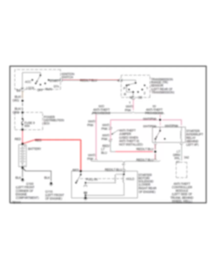
Anti-theft Wiring Diagram for Mercury Cougar XR7 1996
 https://portal-diagnostov.com/license.html
Automotive Electricians Portal FZCO
Automotive Electricians Portal FZCO
https://portal-diagnostov.com/license.html
https://portal-diagnostov.com/license.html
Automotive Electricians Portal FZCO
Automotive Electricians Portal FZCOList of elements for Anti-theft Wiring Diagram for Mercury Cougar XR7 1996:
- 0.162k
- 20a
- Acc fuse 10a
- Alarm ind
- Anti-theft controller module (left side of trunk, behind wheel well)
- Anti-theft ignition sensor (in steering column, at ignition switch)
- Anti-theft in-line fuse holder (left front of trunk, above wheel well)
- Both doors lock out
- C226
- C232
- C251
- C408
- C409
- C455
- C457
- Door ajar in
- Door ajar out
- Door disarm in
- Door lock actuators
- Door open in
- Driver door unlock out
- Driver's door unlock
- Exterior lights system
- G200
- G203 ground bus (behind right cowl panel, near front door sill)
- Gnd
- Ground bus (behind left cowl panel, near front door sill)
- Headlights system
- Horn out
- Horns system (horn relay)
- Hot at all times
- Hot in acc or run
- Ignition tamper sens
- Instrument cluster
- Instrument cluster system (indicator lamp module)
- Int lps fuse 10a
- Left door ajar switch (top rear of left door)
- Left door anti-theft disarm switch (top of left door, part of door lock cylinder)
- Lo beam out
- Nca
- Parking lmp out
- Passenger door unlock out
- Primary junction block
- Pwr (acc/run)
- Pwr (hat)
- Red
- Remote/keyless entry module (left side of trunk, above wheel well, behind trim)
- Right door ajar switch (top rear of right door)
- Right door anti-theft disarm switch (top of right door, part of door lock cylinder)
- Seat/lock circuit breaker 20a
- Starter interrupt
- Starting/ charging system
- Trunk lid in
- Trunk lock tamper switch (center of trunk lid, near cylinder lock assembly)
- Unlocks door in
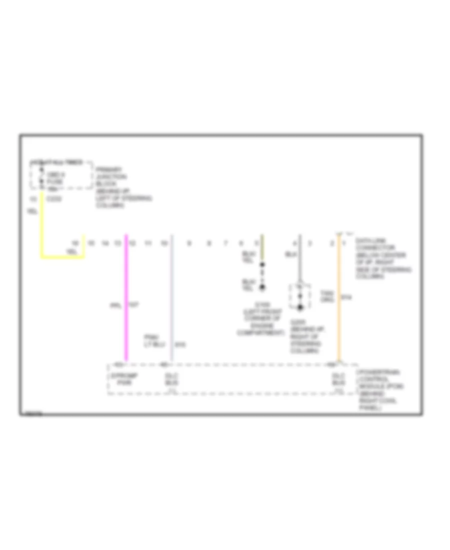
COMPUTER DATA LINES
Computer Data Lines for Mercury Cougar XR7 1996
 https://portal-diagnostov.com/license.html
Automotive Electricians Portal FZCO
Automotive Electricians Portal FZCO
https://portal-diagnostov.com/license.html
https://portal-diagnostov.com/license.html
Automotive Electricians Portal FZCO
Automotive Electricians Portal FZCOList of elements for Computer Data Lines for Mercury Cougar XR7 1996:
- C232
- Data link connector (below center of i/p, right side of steering column)
- Dlc bus (+)
- Dlc bus (-)
- Epromp pwr
- G100 (left front corner of engine compartment)
- G205 (behind i/p, right of steering column)
- Hot at all times
- Obd ii fuse 10a
- Powertrain control module (pcm) (behind right cowl panel)
- Primary junction block (behind i/p, left of steering column)
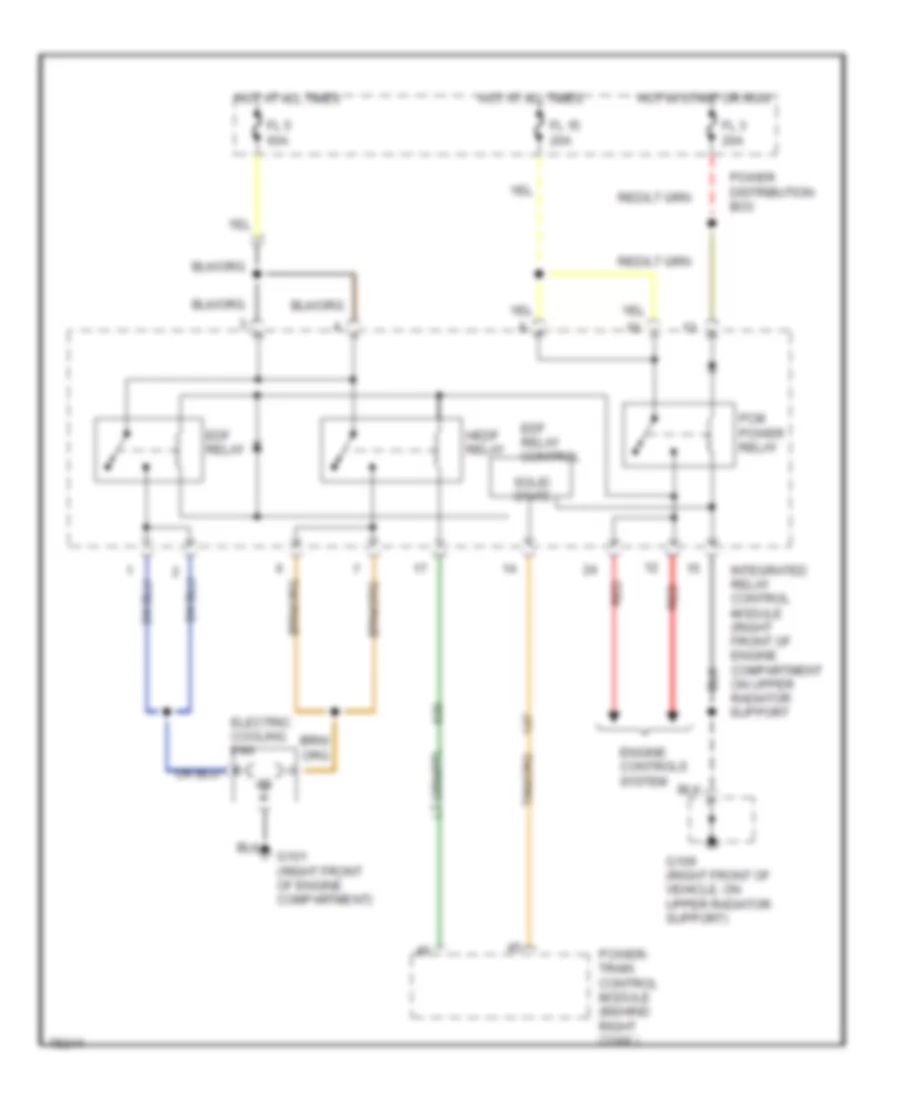
COOLING FAN
Cooling Fan Wiring Diagram for Mercury Cougar XR7 1996
 https://portal-diagnostov.com/license.html
Automotive Electricians Portal FZCO
Automotive Electricians Portal FZCO
https://portal-diagnostov.com/license.html
https://portal-diagnostov.com/license.html
Automotive Electricians Portal FZCO
Automotive Electricians Portal FZCOList of elements for Cooling Fan Wiring Diagram for Mercury Cougar XR7 1996:
- Edf relay
- Edf relay control
- Electric cooling fan
- Engine controls system
- Fl 15 20a
- Fl 3 20a
- Fl 5 60a
- G101 (right front of engine compartment)
- G109 (right front of vehicle, on upper radiator support)
- Hedf relay
- Hot at all times
- Hot in start or run
- Integrated relay control module (right front of engine compartment on upper radiator support
- Pcm power relay
- Power distribution box
- Power- train control module (behind right cowl)
- Red
- Solid state
CRUISE CONTROL
Cruise Control Wiring Diagram for Mercury Cougar XR7 1996
 https://portal-diagnostov.com/license.html
Automotive Electricians Portal FZCO
Automotive Electricians Portal FZCO
https://portal-diagnostov.com/license.html
https://portal-diagnostov.com/license.html
Automotive Electricians Portal FZCO
Automotive Electricians Portal FZCOList of elements for Cruise Control Wiring Diagram for Mercury Cougar XR7 1996:
- 15a
- Acc fuse 10a
- Accel
- Brake on/off (boo) switch (on brake pedal support)
- Brake on/off sw in
- Brake travel input
- Brake travel switch (on brake pedal support)
- C208
- C226
- C232
- C236
- C237
- C238
- C240
- C243
- C245
- C298
- Clockspring assembly (top of steering column)
- Coast
- Fuse 10
- G109
- G200
- G205
- G407 (center rear of trunk, on lock support)
- Gnd
- Ground bus (behind i/p, right of steering column)
- Ground bus (behind left cowl panel, near front of door sill)
- Ground bus (right front of vehicle, mounted on upper radiator support)
- Horn relay
- Horn switch
- Hot at all times
- Hot in run or acc
- Left hi mount stop lamp
- Left rear stop/ park/ turn lamp
- Lt gnr
- Multi-function switch
- Nca
- Off
- Ohms
- Power (hot in run)
- Power distribution box (left side of engine compt.)
- Primary junction block left side of i/p)
- Resume
- Right hi mount stop lamp
- Right rear stop/ park/ turn lamp
- Secondary junction block (right side of steering column)
- Set/
- Speed cont sw gnd
- Speed cont sw in
- Speed control amplifier (behind left fender apron)
- Speed control switch assembly
- Stop/ haz fuse 15a
- Vehicle speed input
- Vehicle speed sensor (vss) (left rear of trans- mission)
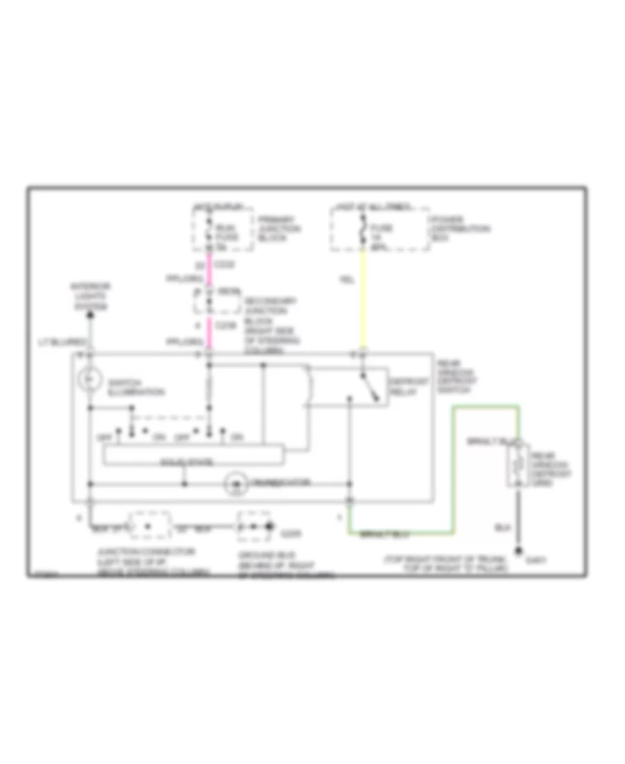
DEFOGGERS
Defogger Wiring Diagram for Mercury Cougar XR7 1996
 https://portal-diagnostov.com/license.html
Automotive Electricians Portal FZCO
Automotive Electricians Portal FZCO
https://portal-diagnostov.com/license.html
https://portal-diagnostov.com/license.html
Automotive Electricians Portal FZCO
Automotive Electricians Portal FZCOList of elements for Defogger Wiring Diagram for Mercury Cougar XR7 1996:
- (top right front of trunk, top of right "d" pillar)
- C232
- C233
- C238
- Defrost relay
- Fuse 40a
- G205
- G401
- Ground bus (behind i/p, right of steering column)
- Hot at all times
- Hot in run
- Interior lights system
- Junction connector (left side of i/p, above steering column)
- Off
- On indicator
- Power distribution box
- Primary junction block
- Rear window defrost grid
- Rear window defrost switch
- Run fuse 5a
- Secondary junction block (right side of steering column)
- Solid state
- Switch illumination
ELECTRONIC POWER STEERING
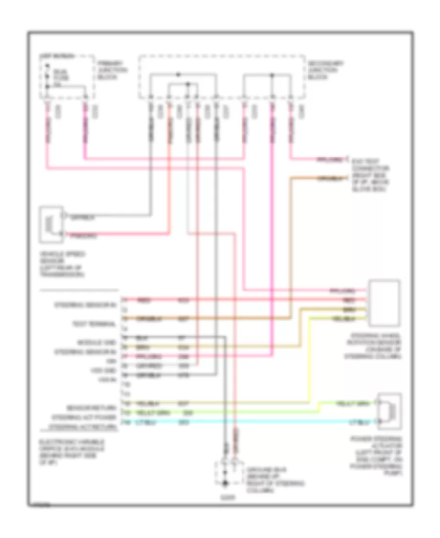
Electronic Power Steering Wiring Diagram for Mercury Cougar XR7 1996
 https://portal-diagnostov.com/license.html
Automotive Electricians Portal FZCO
Automotive Electricians Portal FZCO
https://portal-diagnostov.com/license.html
https://portal-diagnostov.com/license.html
Automotive Electricians Portal FZCO
Automotive Electricians Portal FZCOList of elements for Electronic Power Steering Wiring Diagram for Mercury Cougar XR7 1996:
- red
- C226
- C232
- C233
- C236
- C237
- C238
- C240
- Electronic variable orifice (evo) module (behind right side of i/p)
- Evo test connector (right side of i/p, above glove box)
- G205
- Ground bus (behind i/p, right of steering column)
- Hot in run
- Ign
- Module gnd
- Power steering actuator (left front of eng compt, on power steering pump)
- Primary junction block
- Red
- Run fuse 5a
- Secondary junction block
- Sensor return
- Steering act power
- Steering act return
- Steering sensor in
- Steering wheel rotation sensor (on base of steering column)
- Test terminal
- Vehicle speed sensor (left rear of transmission)
- Vss gnd
- Vss in
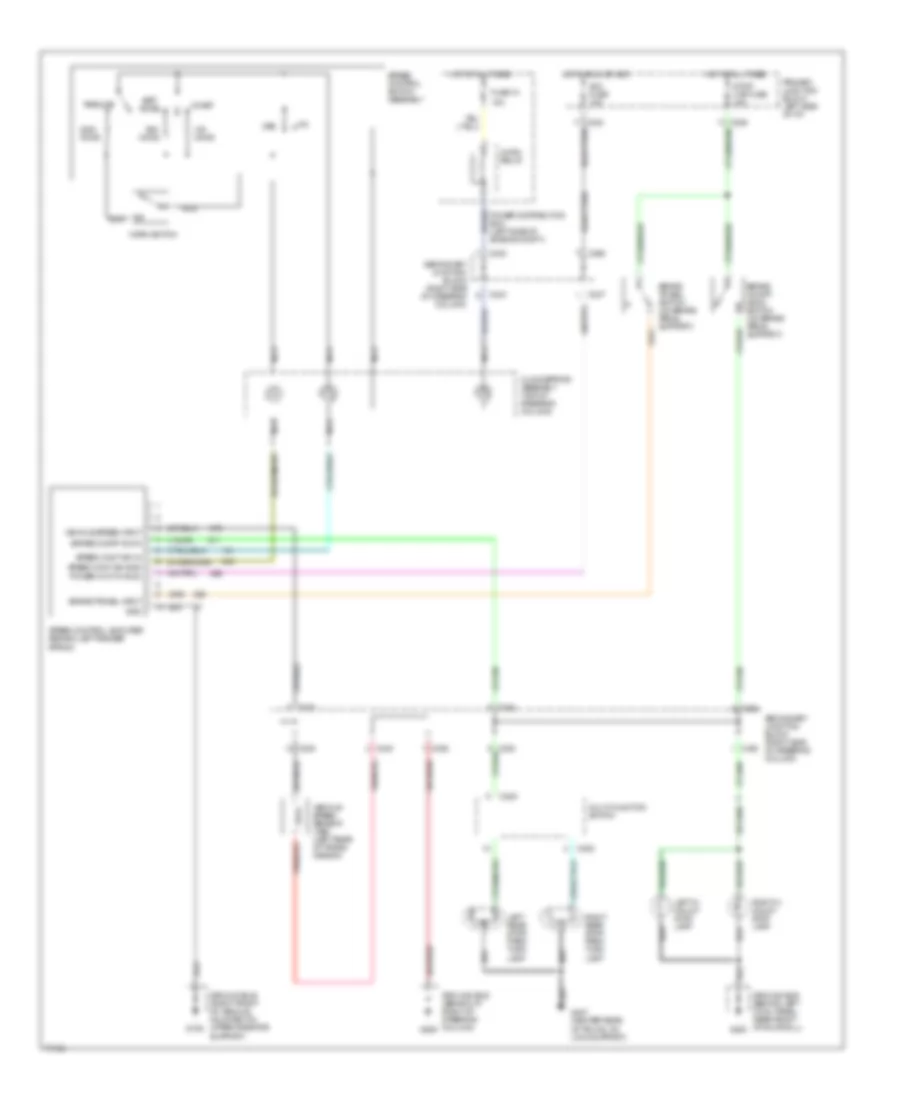
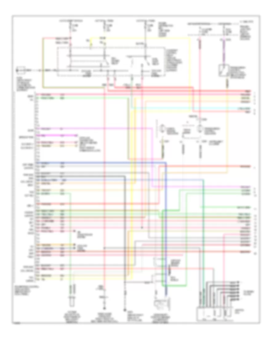
ENGINE PERFORMANCE
3.8L
3.8L, Engine Performance Wiring Diagrams (1 of 3) for Mercury Cougar XR7 1996
 https://portal-diagnostov.com/license.html
Automotive Electricians Portal FZCO
Automotive Electricians Portal FZCO
https://portal-diagnostov.com/license.html
https://portal-diagnostov.com/license.html
Automotive Electricians Portal FZCO
Automotive Electricians Portal FZCOList of elements for 3.8L, Engine Performance Wiring Diagrams (1 of 3) for Mercury Cougar XR7 1996:
- (behind right side of i/p, on "a" pillar)
- Accs
- Air conditioning system
- C 1995 vftc
- C232
- C250
- C251
- Check engine indicator
- Ckp feed
- Ckp rtn
- Ckp/cmp sensor shield
- Cluster fuse 5a
- Coil drv #1
- Coil drv #2
- Constant control relay module (right front of eng compt, on upper radiator support)
- Cooling fans system
- Crankshaft position sensor (lower right front of eng)
- Data link connector (below center of i/p, right side of steering column)
- Dlc bus (+)
- Dlc bus (-)
- Ect
- Epromp pwr
- Evap
- Evr
- Fpm
- Fuel pump relay
- Fuse 20a
- G109 (rigth front of vehicle, mounted on upper radiator support)
- G203
- Gnd
- Hfc
- Ho2s #3
- Hot at all times
- Hot in run
- Hot in start or run
- Iat
- Ignition coil
- Instrument cluster
- Kapwr
- Maf rtn
- Mil
- Nca
- Oct adj
- Octane adjust plug (right rear of eng compt, near pcm)
- Pcm power relay
- Pcm shield
- Power distribution box (left side of eng compt)
- Powertrain control module (pcm) (behind right cowl panel)
- Primary junction block (left of steering column)
- Pwr gnd
- Radio noise capacitor (right front of eng, near ignition coil)
- Red
- Run fuse 5a
- Ss #1
- Ss #2
- Tach
- Tacho- meter
- Tcc
- Tcs
- Tft
- To spark plugs
- Transmission control indicator
- Transmission control switch (tcc) (below front of console)
- Vss (-)
3.8L, Engine Performance Wiring Diagrams (2 of 3) for Mercury Cougar XR7 1996
 https://portal-diagnostov.com/license.html
Automotive Electricians Portal FZCO
Automotive Electricians Portal FZCO
https://portal-diagnostov.com/license.html
https://portal-diagnostov.com/license.html
Automotive Electricians Portal FZCO
Automotive Electricians Portal FZCOList of elements for 3.8L, Engine Performance Wiring Diagrams (2 of 3) for Mercury Cougar XR7 1996:
- (behind i/p, right of steering column)
- (left front corner of engine compartment)
- (left rear of transmission) output shaft speed (oss) sensor
- (lower right front of eng) camshaft position sensor
- (on throttle body) idle air control (iac) valve
- C 1995 vftc c 1995 vftc
- C236
- C237
- C238
- C240
- Egr vacuum regulator (evr) solenoid) (top right of eng)
- Evaporative emission (evap) canister purge valve (behind right headlamps)
- Evaporative emission (evap) purge flow sensor (behind right headlamps)
- Fuel injector #1
- Fuel injector #2
- Fuel injector #3
- Fuel injector #4
- Fuel injector #5
- Fuel injector #6
- Fuel pump/ fuel gauge sender (in top of fuel tank)
- G100
- G203 (behind right cowl panel)
- G205
- Inertia fuel shut-off (ifs) switch (left side of trunk, behind trim panel assembly)
- Mass air flow (maf) sensor (in air intake assembly)
- Red
- Secondary junction block (right side of steering column)
- Tan
- Vehicle speed sensor (vss) (left rear of transmission)
3.8L, Engine Performance Wiring Diagrams (3 of 3) for Mercury Cougar XR7 1996
 https://portal-diagnostov.com/license.html
Automotive Electricians Portal FZCO
Automotive Electricians Portal FZCO
https://portal-diagnostov.com/license.html
https://portal-diagnostov.com/license.html
Automotive Electricians Portal FZCO
Automotive Electricians Portal FZCOList of elements for 3.8L, Engine Performance Wiring Diagrams (3 of 3) for Mercury Cougar XR7 1996:
- 4r70w transmission
- A/c pres
- Air conditioning system
- All times
- Boo
- Brake on/off (boo) switch
- C 1995 vftc c 1995 vftc
- C226
- C238
- C240
- Cam pos sens
- Coil drv #3
- Electronic pressure control (epc)
- Engine coolant temperature sensor (top right front of eng)
- Epc sol
- Evap canp
- Fpm
- Fuel inj 1
- Fuel inj 2
- Fuel inj 3
- Fuel inj 4
- Fuel inj 5
- Fuel inj 6
- G100 (left front corner of engine compartment)
- Heated oxygen sensor #1 (lower right rear of eng, in exhaust manifold)
- Heated oxygen sensor #2 (lower left rear of eng, in exhaust manifold)
- Heated oxygen sensor #3 (rear of eng, in exhaust pipe)
- Heated oxygen sensor #4 (rear of eng, in exhaust pipe)
- Heater ctrl
- Ho2s #1
- Ho2s #2
- Ho2s #4
- Ho2s 1
- Ho2s 2
- Ho2s 3
- Ho2s 4
- Hot at
- Iac valve
- Intake air temperature sensor (in air filter assembly)
- Maf sens
- Nca
- Oss sens
- Pfe sens
- Powertrain control module (pcm) (behind right cowl panel)
- Pressure feedback egr sensor (top right rear of eng)
- Primary junction block (left of steering column)
- Pwr
- Pwr gnd
- Red
- Ref volt
- Secondary junction block (left of steering column)
- Shift solenoids (ss)
- Sig rtn
- Solenoid
- Ss1
- Ss2
- Stop/haz fuse 15a
- Tan
- Tcl
- Throttle position sensor (on throttle body)
- Torque converter clutch (tcc) solenoid
- Tp sens
- Tr sens
- Transmission fluid temperature sensor
- Transmission range (tr) sensor (left rear of transmission)
- Vpwr
- Vss +
- Wac
4.6L
4.6L, Engine Performance Wiring Diagrams (1 of 3) for Mercury Cougar XR7 1996
 https://portal-diagnostov.com/license.html
Automotive Electricians Portal FZCO
Automotive Electricians Portal FZCO
https://portal-diagnostov.com/license.html
https://portal-diagnostov.com/license.html
Automotive Electricians Portal FZCO
Automotive Electricians Portal FZCOList of elements for 4.6L, Engine Performance Wiring Diagrams (1 of 3) for Mercury Cougar XR7 1996:
- (behind right side of i/p, on "a" pillar)
- Accs
- Air conditioning system
- C 1995 vftc
- C232
- C250
- C251
- Check engine indicator
- Ckp feed
- Ckp rtn
- Cluster fuse 5a
- Cmp sensor shield
- Coil drv #1
- Coil drv #2
- Constant control relay module (right front of eng compt, on upper radiator support)
- Cooling fans system
- Crankshaft position sensor (lower right front of eng)
- Data link connector (below center of i/p, right side of steering column)
- Dlc bus (+)
- Dlc bus (-)
- Ect
- Epromp pwr
- Evap
- Evr
- Fpm
- Fuel pump relay
- Fuse 20a
- G109 (rigth front of vehicle, mounted on upper radiator support)
- G203
- Gnd
- Hedf rly ctrl
- Ho2s #3
- Hot at all times
- Hot in run
- Hot in start or run
- Iat
- Icm
- Instrument cluster
- Kapwr
- Left ignition coil
- Left radio noise capacitor (left front of eng)
- Maf rtn
- Mil
- Nca
- Oct adj
- Octane adjust plug (right rear of eng compt, near pcm)
- Pcm power relay
- Pcm shield
- Power distribution box (left side of eng compt)
- Powertrain control module (pcm) (behind right cowl panel)
- Primary junction block (left of steering column)
- Pwr gnd
- Red
- Right ignition coil
- Right radio noise capacitor (right front of eng)
- Run fuse 5a
- Ss #1
- Ss #2
- Tach
- Tacho- meter
- Tcc
- Tcs
- Tft
- To spark plugs
- Transmission control indicator
- Transmission control switch (tcc) (below front of console)
- Vss (-)
- Warning systems
4.6L, Engine Performance Wiring Diagrams (2 of 3) for Mercury Cougar XR7 1996
 https://portal-diagnostov.com/license.html
Automotive Electricians Portal FZCO
Automotive Electricians Portal FZCO
https://portal-diagnostov.com/license.html
https://portal-diagnostov.com/license.html
Automotive Electricians Portal FZCO
Automotive Electricians Portal FZCOList of elements for 4.6L, Engine Performance Wiring Diagrams (2 of 3) for Mercury Cougar XR7 1996:
- (behind i/p, right of steering column)
- (left front corner of engine compartment)
- (left rear of transmission) output shaft speed (oss) sensor
- (lower right front of eng) camshaft position sensor
- (on throttle body) idle air control (iac) valve
- C 1995 vftc
- C236
- C237
- C238
- C240
- Egr vacuum regulator (evr) solenoid) (top right of eng)
- Evaporative emission (evap) canister purge valve (behind right headlamps)
- Evaporative emission (evap) purge flow sensor (behind right headlamps)
- Fuel injector #1
- Fuel injector #2
- Fuel injector #3
- Fuel injector #4
- Fuel injector #5
- Fuel injector #6
- Fuel injector #7
- Fuel injector #8
- Fuel pump/ fuel gauge sender (in top of fuel tank)
- G100
- G203 (behind right cowl panel)
- G205
- Inertia fuel shut-off (ifs) switch (left side of trunk, behind trim panel assembly)
- Mass air flow (maf) sensor (in air intake assembly)
- Red
- Secondary junction block (right side of steering column)
- Tan
- Tan/red
- Vehicle speed sensor (vss) (left rear of transmission)
4.6L, Engine Performance Wiring Diagrams (3 of 3) for Mercury Cougar XR7 1996
 https://portal-diagnostov.com/license.html
Automotive Electricians Portal FZCO
Automotive Electricians Portal FZCO
https://portal-diagnostov.com/license.html
https://portal-diagnostov.com/license.html
Automotive Electricians Portal FZCO
Automotive Electricians Portal FZCOList of elements for 4.6L, Engine Performance Wiring Diagrams (3 of 3) for Mercury Cougar XR7 1996:
- 4r70w transmission
- A/c pres
- Air conditioning system
- All times
- Boo
- Brake on/off (boo) switch
- C 1995 vftc c 1995 vftc
- C226
- C238
- C240
- Cam pos sens
- Coil drv #3
- Coil drv #4
- Electronic pressure control (epc)
- Engine coolant temperature sensor (top right front of eng)
- Epc sol
- Evap canp
- Fpm
- Fuel inj 1
- Fuel inj 2
- Fuel inj 3
- Fuel inj 4
- Fuel inj 5
- Fuel inj 6
- Fuel inj 7
- Fuel inj 8
- G100 (left front corner of engine compartment)
- Heated oxygen sensor #1 (lower right rear of eng, in exhaust manifold)
- Heated oxygen sensor #2 (lower left rear of eng, in exhaust manifold)
- Heated oxygen sensor #3 (rear of eng, in exhaust pipe)
- Heated oxygen sensor #4 (rear of eng, in exhaust pipe)
- Heater ctrl
- Ho2s #1
- Ho2s #2
- Ho2s #4
- Ho2s 1
- Ho2s 2
- Ho2s 3
- Ho2s 4
- Hot at
- Iac valve
- Intake air temperature sensor (in air filter assembly)
- Maf sens
- Nca
- Oss sens
- Pfe sens
- Powertrain control module (pcm) (behind right cowl panel)
- Pressure feedback egr sensor (top right rear of eng)
- Primary junction block (left of steering column)
- Pwr
- Pwr gnd
- Red
- Ref volt
- Secondary junction block (left of steering column)
- Shift solenoids (ss)
- Sig rtn
- Solenoid
- Ss1
- Ss2
- Stop/haz fuse 15a
- Tan
- Tan/red
- Tcl
- Throttle position sensor (on throttle body)
- Torque converter clutch (tcc) solenoid
- Tp sens
- Tr sens
- Transmission fluid temperature sensor
- Transmission range (tr) sensor (left rear of transmission)
- Vpwr
- Vss +
- Wac
EXTERIOR LIGHTS
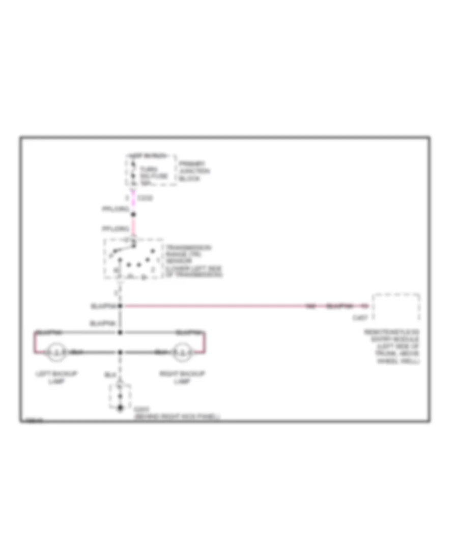
Back-up Lamps Wiring Diagram for Mercury Cougar XR7 1996
 https://portal-diagnostov.com/license.html
Automotive Electricians Portal FZCO
Automotive Electricians Portal FZCO
https://portal-diagnostov.com/license.html
https://portal-diagnostov.com/license.html
Automotive Electricians Portal FZCO
Automotive Electricians Portal FZCOList of elements for Back-up Lamps Wiring Diagram for Mercury Cougar XR7 1996:
- C232
- C457
- G203 (behind right kick panel)
- Hot in run
- Left backup lamp
- Primary junction block
- Remote/keyless entry module (left side of trunk, above wheel well)
- Right backup lamp
- Transmission range (tr) sensor (lower left side of transmission)
- Turn sig fuse 10a
Exterior Lamps Wiring Diagram for Mercury Cougar XR7 1996
 https://portal-diagnostov.com/license.html
Automotive Electricians Portal FZCO
Automotive Electricians Portal FZCO
https://portal-diagnostov.com/license.html
https://portal-diagnostov.com/license.html
Automotive Electricians Portal FZCO
Automotive Electricians Portal FZCOList of elements for Exterior Lamps Wiring Diagram for Mercury Cougar XR7 1996:
- Above wheel well)
- Anti-theft controller module (left side of trunk, behind wheel well)
- Autolamp dual coil relay (behind i/p, right side of steering column)
- Brake on/ off (boo) switch (top of brake pedal)
- C208
- C226
- C232
- C236
- C238
- C250
- C251
- Electronic flasher (behind i/p, right side of steering column)
- G108 (left front of vehicle, mounted on upper radiator support)
- G109 (right front of vehicle, mounted on upper radiator support)
- G203 (behind right cowl panel)
- G205
- G205 (behind i/p, right of steering column)
- G407 (center rear of trunk, on lock support)
- Ground bus (behind i/p, right of steering column)
- Hazard
- Hazard switch
- High mount stop lamp
- Hot at all times
- Hot in run
- Instrument cluster
- J/c
- Junction connector (left side of i/p, above steering column)
- Left
- Left front park lamp
- Left front park/ turn lamp
- Left led bar (t-bird only)
- Left license lamp
- Left rear park/ turn lamp
- Left turn ind
- Main light switch head
- Multi- function switch
- Normal
- Off
- Park
- Park lamp in-line fuse holder (left front of trunk, above wheel well)
- Park lps fuse 10a
- Primary junction block
- Primary junction block (behind i/p, left of steering column)
- Remote/ keyless entry module (left side of trunk, c456
- Right
- Right front park lamp
- Right front park/ turn lamp
- Right led bar (t-bird only)
- Right license lamp
- Right rear park/ turn lamp
- Right turn ind
- Secondary junction block (right side of steering column)
- Solid state
- Stop/haz fuse 15a
- Turn left
- Turn right
- Turn sig fuse 10a
- Turn switches
- W/ autolamps/ delayed exit only
GROUND DISTRIBUTION
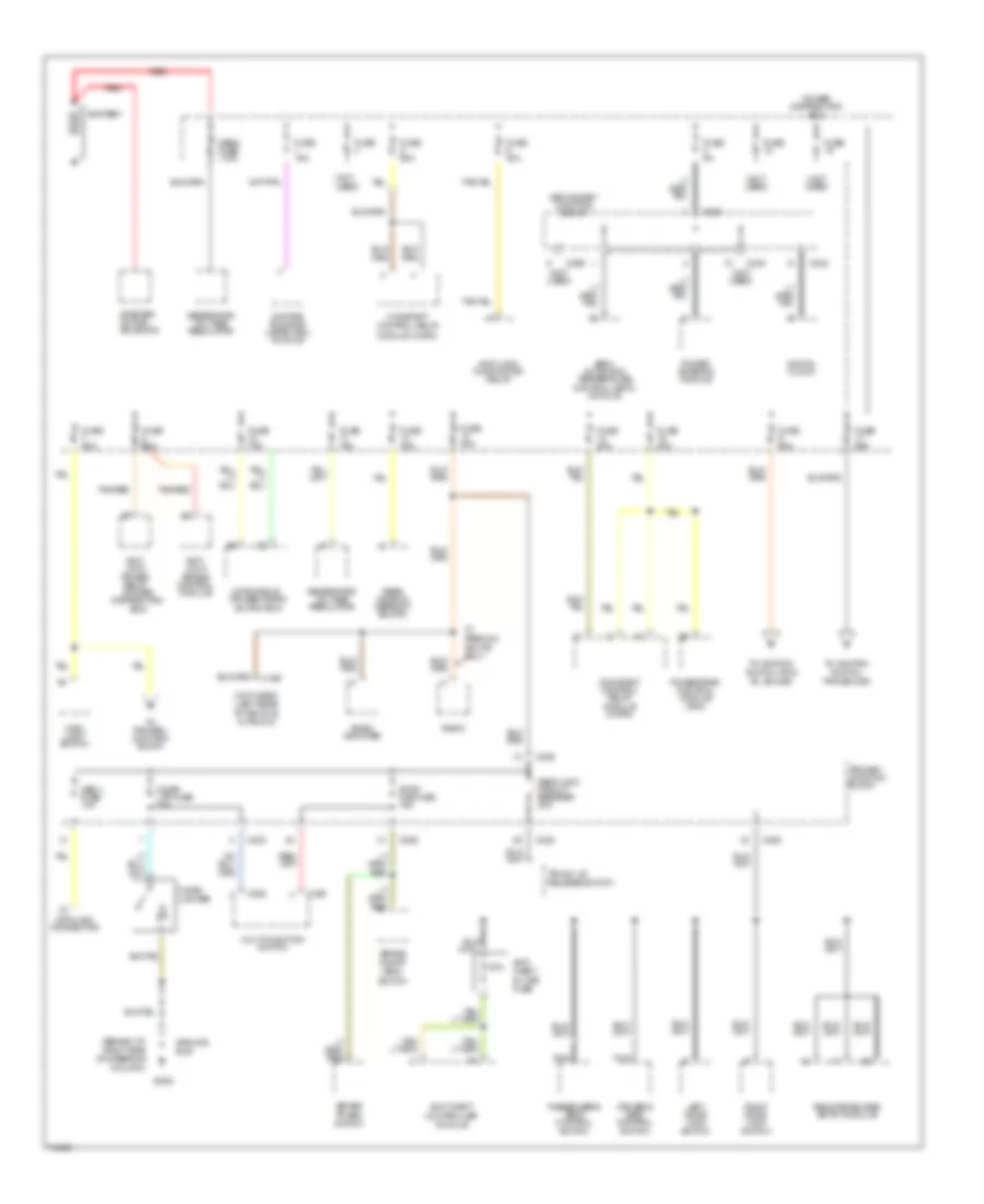
Ground Distribution Wiring Diagram (1 of 3) for Mercury Cougar XR7 1996
 https://portal-diagnostov.com/license.html
Automotive Electricians Portal FZCO
Automotive Electricians Portal FZCO
https://portal-diagnostov.com/license.html
https://portal-diagnostov.com/license.html
Automotive Electricians Portal FZCO
Automotive Electricians Portal FZCOList of elements for Ground Distribution Wiring Diagram (1 of 3) for Mercury Cougar XR7 1996:
- (in power distribution box) anti-lock power relay
- (right side of steering column) (not used)
- 3.8l
- 3.8l only
- 4.6l only
- 87a
- A/c high pressure cutout/fan switch
- Abs test connector
- Anti- lock pump motor relay
- Anti-lock brake control module
- Anti-lock brake pump motor speed sensor shield
- Battery
- Brake fluid level switch
- Brake sensor shields
- C240
- C250
- Camshaft position (cmp) sensor
- Ckp sensor shield
- Ckp/cmp sensor shield
- Cmp sensor shield
- Constant control relay module
- Data link connector
- Engine compartment lamp
- Engine coolant level sensor
- Engine coolant temperature sensor
- Evaporative emission (evap) purge flow sensor
- G100 (left front corner of engine compartment)
- G108 (left front of vehicle, mounted on upper radiator support)
- G109 (right front of vehicle, mounted on upper radiator support)
- G110 (left front of engine)
- G120 (at t/o for fuel injection #1)
- G203 (behind right side of i/p, on "a" pillar)
- G206 (behind right center of i/p)
- G401 (top right front of trunk, top of right "d" pillar)
- Ground bus
- Instrument cluster
- Left front
- Left front park lamp
- Left front park/ turn lamp
- Left headlamp
- Left rear
- Mass air flow (maf) sensor
- Nca
- Pcm shield
- Powertrain control module
- Powertrain control module (pcm)
- Radio
- Radio amplifier
- Rear window defrost grid
- Right front
- Right front park lamp
- Right front park/ turn lamp
- Right headlamp
- Right rear
- Solenoid control valve body
- Speed control amplifier
- Washer motor
- Windshield wiper motor
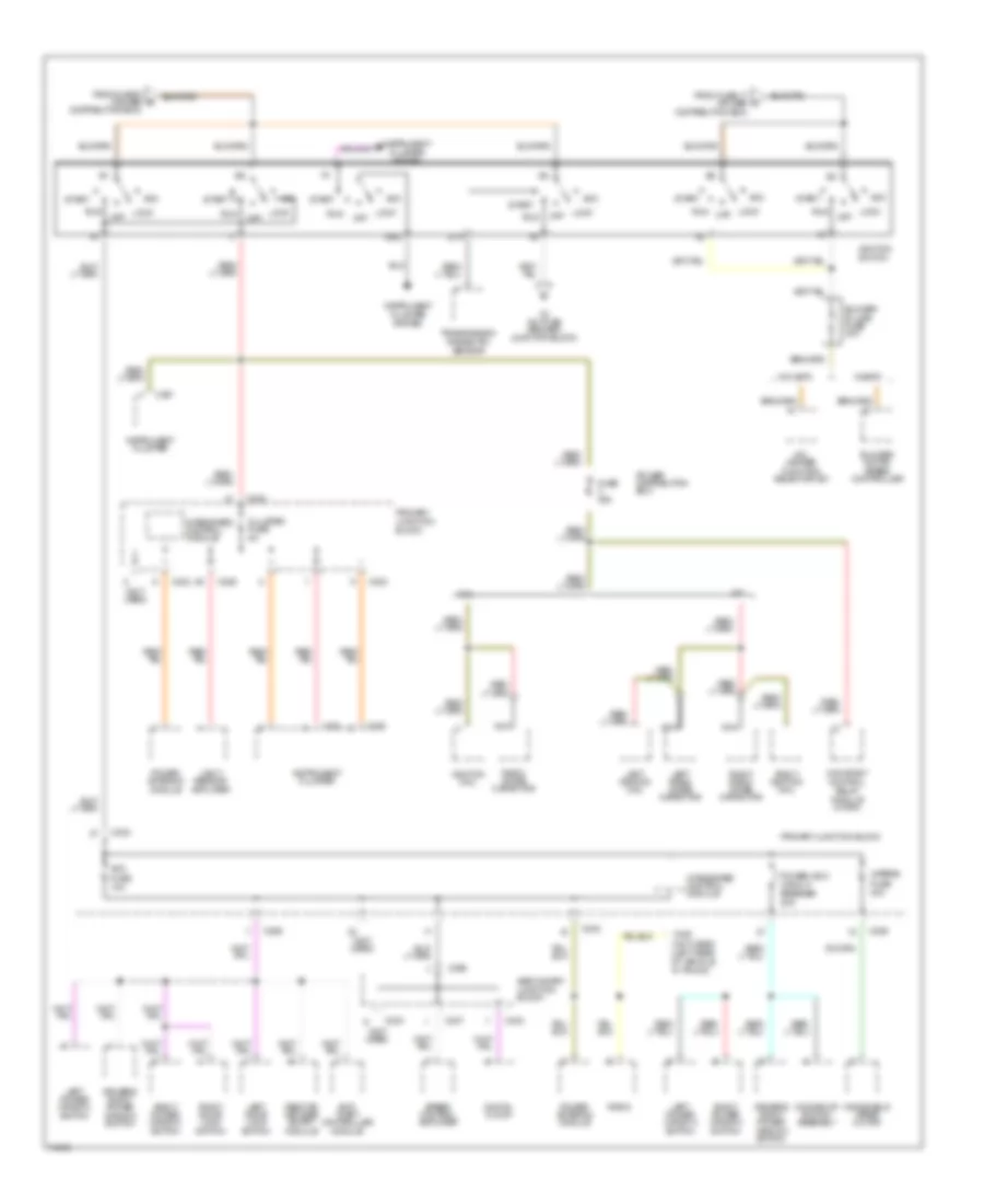
Ground Distribution Wiring Diagram (2 of 3) for Mercury Cougar XR7 1996
 https://portal-diagnostov.com/license.html
Automotive Electricians Portal FZCO
Automotive Electricians Portal FZCO
https://portal-diagnostov.com/license.html
https://portal-diagnostov.com/license.html
Automotive Electricians Portal FZCO
Automotive Electricians Portal FZCOList of elements for Ground Distribution Wiring Diagram (2 of 3) for Mercury Cougar XR7 1996:
- (in primary junction block) integrated control module
- (top center of i/p) not used)
- A/c-heater function selector switch
- Air bag diagnostic monitor
- Ashtray lamp
- Autolamp dual coil relay
- Blend door motor control
- Blower motor speed controller
- Blower motor switch
- Blower resistors
- C236
- C237
- C240
- C242
- C245
- C246
- C250
- C251
- C263
- C299
- Cigar lighter
- Data link connector
- Digital clock
- Electronic flasher
- Electronic variable orifice (evo) module
- Electronic variable orifice module
- Fuel pump/ fuel gauge sender
- G201 (behind right side of i/p)
- G205 (behind i/p, right of steering column)
- Gnd
- Ground bus
- Ignition switch
- Indicator lamp module
- Instrument cluster
- Junction connector
- Left instrument panel lamp
- Main light switch
- Panel dimmer switch
- Power antenna module
- Powertrain control module
- Radio
- Rear window defrost switch
- Right instrument panel light
- Secondary junction block
- Semi- automatic temperature control module
- Shift lock actuator
- Transmission control switch (tcs)
- Vehicle speed sensor (vss)
- W/ evo power steering
- W/o satc
- W/satc
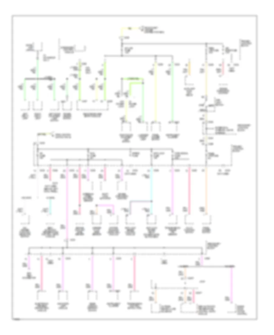
Ground Distribution Wiring Diagram (3 of 3) for Mercury Cougar XR7 1996
 https://portal-diagnostov.com/license.html
Automotive Electricians Portal FZCO
Automotive Electricians Portal FZCO
https://portal-diagnostov.com/license.html
https://portal-diagnostov.com/license.html
Automotive Electricians Portal FZCO
Automotive Electricians Portal FZCOList of elements for Ground Distribution Wiring Diagram (3 of 3) for Mercury Cougar XR7 1996:
- (behind left cowl panel, near front door sill)
- (in
- (in center of left door) (not used)
- (under left front seat) (not used)
- Anti-theft control module
- Anti-theft ignition sensor
- C317
- C505
- Dome/map lamps
- Driver's
- Driver's right power window switch
- Driver's seat control switch
- Fuel pump/ fuel gauge sender
- G200
- G203 (behind right cowl panel)
- G407 (center rear of trunk, on lock support)
- G600 (in passenger's door)
- Ground bus
- Left backup lamp
- Left door anti-theft disarm switch
- Left door courtesy lamp
- Left door lock switch
- Left hi mount stop lamp
- Left led bar
- Left license lamp
- Left power window switch
- Left rear stop/park/ turn lamp
- Luggage compartment lamp
- Moonroof switch assembly
- Nca
- Passenger's seat control switch
- Power mirror switch
- Remote keyless entry module
- Remote/keyless entry module
- Right backup lamp
- Right door anti-theft disarm switch
- Right door courtesy lamp
- Right door lock switch
- Right hi mount stop lamp
- Right led bar
- Right license lamp
- Right power window switch
- Right rear stop/park/ turn lamp
- Seat belt switch
- Seat)
- Thunderbird only
- Trunk lid release solenoid
- Trunk lock tamper switch
- W/ rke
- W/ rke only
- W/o rke
HEADLIGHTS
Headlight Wiring Diagram, with DRL for Mercury Cougar XR7 1996
 https://portal-diagnostov.com/license.html
Automotive Electricians Portal FZCO
Automotive Electricians Portal FZCO
https://portal-diagnostov.com/license.html
https://portal-diagnostov.com/license.html
Automotive Electricians Portal FZCO
Automotive Electricians Portal FZCOList of elements for Headlight Wiring Diagram, with DRL for Mercury Cougar XR7 1996:
-
-
-
-
-
-
- ground bus (left front of vehicle, mounted on upper radiator support)
- secondary junction block (right side of steering column)
- 200k
- 3.5k
- Acc
- Anti-theft system (anti-theft controller module)
- Auto- lamp ctrl sw
- Autolamp dual coil relay (w/ autolamps only) (behind i/p, right side of steering column)
- Autolamp dual coil rly ctrl
- Brake fluid level switch (on brake fluid reservoir)
- Brake ind out
- C206
- C226
- C232
- C236
- C243
- C245
- C250
- C251
- Cigar ltr fuse 20a
- Cluster fuse 5a
- Daytime running lamps (drl) module (in left front wheel well)
- Delayed exit in
- Dimmer switch
- Exterior lights system
- Flash-to-pass switch
- Fuse 15a
- G108
- G109
- G205 ground bus (behind i/p, right of steering column)
- Gnd
- Ground bus (right front of vehicle, mounted on upper radiator support)
- Head
- Hi beam ind
- Hi beams in
- Hi-beam ind out
- Hot at all times
- Hot in run
- Hot in start or run
- Ignition switch
- Instrument cluster
- Instrument cluster (brake indicator)
- Junction connector (left side of i/p, above steering column)
- Left headlight
- Light sensor/amplifier (w/ autolamps only) (top right side of i/p)
- Lo beam
- Lock
- Main light switch
- Multi- function switch
- Off
- On/off in
- Panel dimmer switch
- Park
- Park brake on in
- Park brake switch (on park brake assembly)
- Pass
- Power distribution box
- Primary junction block
- Primary junction block (behind i/p, left of steering column)
- Pwr (bat)
- Pwr (run)
- Pwr (start/run)
- Right headlight
- Run
- Run fuse 5a
- Secondary junction block (right side of steering column)
- Start
- W/ autolamps/ delayed exit
Headlight Wiring Diagram, without DRL for Mercury Cougar XR7 1996
 https://portal-diagnostov.com/license.html
Automotive Electricians Portal FZCO
Automotive Electricians Portal FZCO
https://portal-diagnostov.com/license.html
https://portal-diagnostov.com/license.html
Automotive Electricians Portal FZCO
Automotive Electricians Portal FZCOList of elements for Headlight Wiring Diagram, without DRL for Mercury Cougar XR7 1996:
-
-
-
-
-
-
- 200k
- 3.5k
- Anti-theft system (anti-theft controller module)
- Auto- lamp ctrl sw
- Autolamp dual coil relay (w/ autolamps only) (behind i/p, right side of steering column)
- Autolamp dual coil rly ctrl
- C206
- C226
- C232
- C250
- C251
- Cigar ltr fuse 20a
- Cluster fuse 5a
- Delayed exit in
- Dimmer switch
- Exterior lights system
- Flash-to-pass switch
- G108
- G109
- G205 ground bus (behind i/p, right of steering column)
- Ground bus (left front of vehicle, mounted on upper radiator support)
- Ground bus (right front of vehicle, mounted on upper radiator support)
- Head
- Hi beam ind
- Hot at all times
- Hot in start or run
- Instrument cluster
- Junction connector (left side of i/p, above steering column)
- Left headlight
- Light sensor/amplifier (w/ autolamps only) (top right side of i/p)
- Main light switch
- Multi- function switch
- Off
- On/off in
- Panel dimmer switch
- Park
- Pass
- Primary junction block
- Primary junction block (behind i/p, left of steering column)
- Pwr (bat)
- Pwr (start/run)
- Right headlight
- Secondary junction block (right side of steering column)
- W/ autolamps/ delayed exit
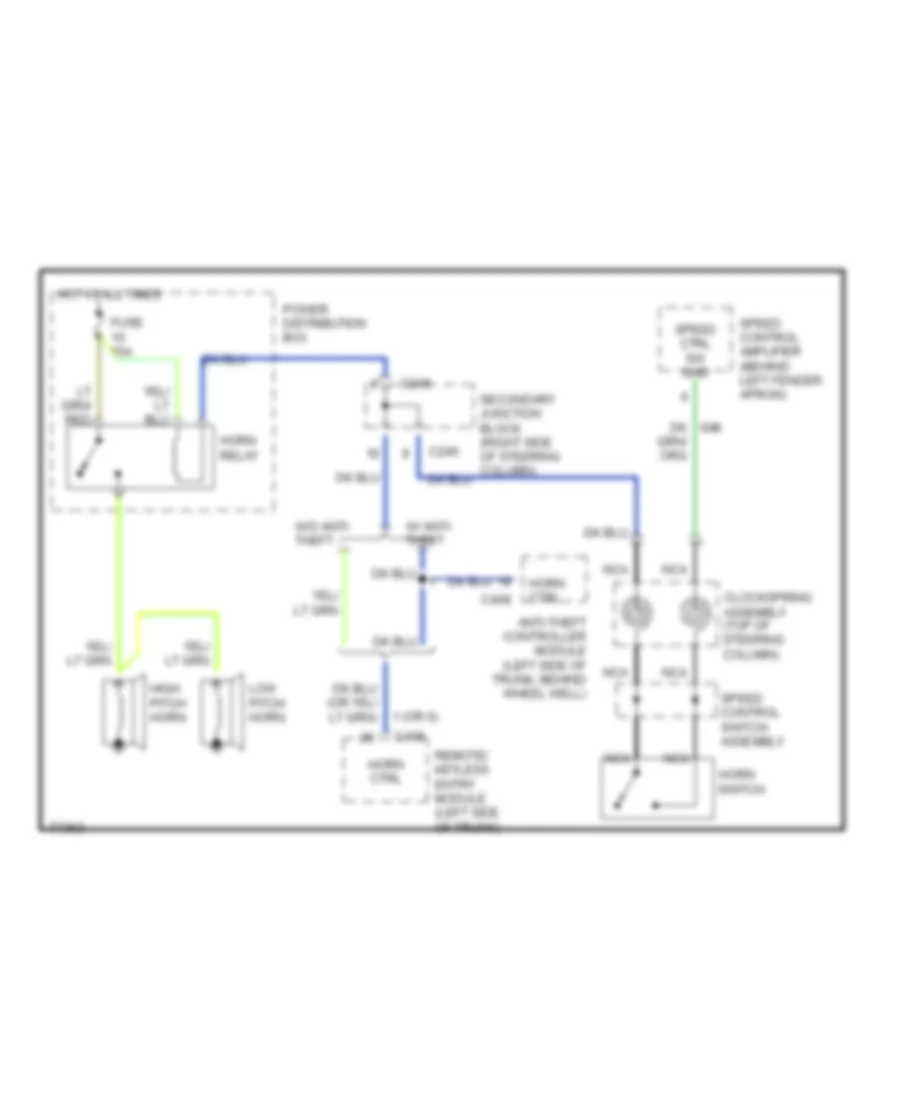
HORN
Horn Wiring Diagram for Mercury Cougar XR7 1996
 https://portal-diagnostov.com/license.html
Automotive Electricians Portal FZCO
Automotive Electricians Portal FZCO
https://portal-diagnostov.com/license.html
https://portal-diagnostov.com/license.html
Automotive Electricians Portal FZCO
Automotive Electricians Portal FZCOList of elements for Horn Wiring Diagram for Mercury Cougar XR7 1996:
- 1 (or 6)
- Anti-theft controller module (left side of trunk, behind wheel well)
- C245
- C408
- C456
- Clockspring assembly (top of steering column)
- Fuse 15a
- High pitch horn
- Horn ctrl
- Horn relay
- Horn switch
- Hot at all times
- Low pitch horn
- Nca
- Power distribution box
- Remote/ keyless entry module (left side of trunk)
- Speed control amplifier (behind left fender apron)
- Speed control switch assembly
- Speed ctrl sw gnd
- W/ anti- theft
- W/o anti- theft
INSTRUMENT CLUSTER
Indicator Lamp Module Wiring Diagram for Mercury Cougar XR7 1996
 https://portal-diagnostov.com/license.html
Automotive Electricians Portal FZCO
Automotive Electricians Portal FZCO
https://portal-diagnostov.com/license.html
https://portal-diagnostov.com/license.html
Automotive Electricians Portal FZCO
Automotive Electricians Portal FZCOList of elements for Indicator Lamp Module Wiring Diagram for Mercury Cougar XR7 1996:
- 3.8l
- 4.6l
- Anti-lock brake control module (below battery)
- Anti-theft control module (left side of trunk, behind wheel well)
- C226
- C232
- C233
- C236
- C240
- C243
- C409
- Door ajar ind
- Engine coolant ind
- Engine coolant level sensor (top of engine coolant level reservoir)
- Fuel pump/ fuel gauge sender (in top of fuel tank)
- G108 ground bus (left front of vehicle, mounted on upper radiator support)
- G205 secondary junction block (right side of steering column)
- Hot in run
- Indicator lamp module (bottom center of i/p)
- Instrument cluster system (anti-slosh check gauge module)
- Junction connector (left side of i/p, above steering column)
- Left door ajar switch
- Low fuel ind
- Off
- Primary junction block
- Right door ajar switch
- Run fuse 5a
- Secondary junction block (right side of steering column)
- Solid state
- Traction assist ind
- Traction assist switch
- W/ anti-theft
- W/o anti-theft
- Washer fluid ind
- Washer fluid level sensor (bottom of washer fluid reservoir)
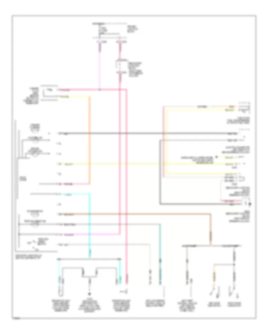
Instrument Cluster Wiring Diagram for Mercury Cougar XR7 1996
 https://portal-diagnostov.com/license.html
Automotive Electricians Portal FZCO
Automotive Electricians Portal FZCO
https://portal-diagnostov.com/license.html
https://portal-diagnostov.com/license.html
Automotive Electricians Portal FZCO
Automotive Electricians Portal FZCOList of elements for Instrument Cluster Wiring Diagram for Mercury Cougar XR7 1996:
- (behind i/p, right of steering column)
- (conn a)
- (conn b)
- (left front of vehicle, mounted on upper radiator support)
- 0.5k
- 20 ohms
- 3.8l
- 4.6l
- A10
- A11
- A12
- A14
- A15
- A16
- A17
- A18
- Acc
- Air bag
- Air bag diagnostic monitor (behind right side of i/p)
- Alarm ind
- Anti- slosh check gauge module
- Anti-lock brakes system
- Anti-lock ind
- Anti-theft control module (left side of trunk, behind wheel well)
- B10
- B11
- B12
- B13
- B14
- Brake fluid level switch (on brake fluid reservoir)
- Brake ind
- C232
- C233
- C236
- C237
- C238
- C240
- C243
- C245
- C250
- C408
- Charge warning ind
- Check gaude ind
- Cluster fuse 5a
- Daytime running lamps module (in left front wheel well)
- Electronic variable orifice (evo) module (behind right side of i/p)
- Engine coolant temp gauge
- Engine coolant temperature sensor (to front of eng)
- Engine oil pressure gauge
- Engine oil pressure switch (lower left front of eng)
- Exterior lights system (multi-function switch)
- Fasten belts ind
- Fuel gauge
- Fuel pump/ fuel gauge sender (in top of fuel tank)
- G108
- G109 ground bus (right front of vehicle, mounted on radiator support)
- G205
- Gnd
- Ground bus
- Headlights system
- Hi beam ind
- Hot at all times
- Hot in park or head
- Hot in run
- Hot in start or run
- Ignition switch
- Illumination lamps
- Indicator lamp module
- Instrument cluster
- Int lps fuse 10a
- Junction connector (left side of i/p, above steering column)
- Left turn ind
- Lock
- Low
- Mil
- Mil ind
- Normal
- Off
- Panel dimmer switch (top left side of i/p)
- Panel lsp fuse 5a
- Park brake switch (on park brake assembly)
- Powertrain control module (behind right cowl panel)
- Primary junction block
- Right turn ind
- Run
- Run fuse 5a
- Secondary junction block (right side of steering column)
- Speed control amplifier (behind left fender apron)
- Speedo- meter
- Start
- Starting/ charging system
- Tach
- Tacho- meter
- Tcil
- Tcil ind
- Vehicle speed sensor (left rear of transmission)
- Volmeter
- Vss
- W/ drl
- W/o drl
- Warning systems (warning chime module)
INTERIOR LIGHTS
Interior Light Wiring Diagram, with Remote/Keyless Entry for Mercury Cougar XR7 1996
 https://portal-diagnostov.com/license.html
Automotive Electricians Portal FZCO
Automotive Electricians Portal FZCO
https://portal-diagnostov.com/license.html
https://portal-diagnostov.com/license.html
Automotive Electricians Portal FZCO
Automotive Electricians Portal FZCOList of elements for Interior Light Wiring Diagram, with Remote/Keyless Entry for Mercury Cougar XR7 1996:
- (left front of vehicle, mounted on upper radiator support)
- (not used)
- 3.5k
- A/c- heater function selector switch
- Autolamp control switch
- Bat
- Bulbs
- C226
- C232
- C233
- C236
- C238
- C240
- C242
- C245
- C246
- C250
- C251
- C258
- C259
- C263
- C295
- C298
- C455
- C456
- C456 bat
- C457
- Control switch (tcs)
- Digital clock
- Dome/ map lamps
- Engine compart- ment lamp
- G108
- G200 (behind left cowl panel, near front of door sill)
- G203 (behind right cowl panel)
- G205 (behind i/p, right of steering column)
- G500 (in driver's door)
- G600 (in pass- enger's door)
- Glove box lamp
- Gnd
- Ground bus
- Headlights system
- Hot at all times
- Hot in head or park
- Instru- ment cluster
- Int lps fuse 10a
- Integrated control module
- Junction connector (left side of i/p, above steering column)
- Lamp
- Left door courtesy lamp
- Left door courtesy lamp switch
- Left door latch switch (top rear of door)
- Left instru- ment panel lamp
- Left vanity lamp
- Lmp ctrl
- Luggage compartment lamp
- Nca
- Off
- Panel dimmer switch
- Panel lps fuse 5a
- Primary junction block (behind i/p, left of steering column)
- Radio solid state
- Red/ pnk
- Red/pnk
- Remote/ keyless entry module (left side of trunk, above wheel well)
- Right door courtesy lamp
- Right door courtesy lamp switch
- Right door latch switch (top rear of door)
- Right instru- ment panel lamp
- Right vanity lamp
- Secondary junction block (right side of steering column)
- Semi- automatic temperature control (satc) module
- Solid state
- Sw input
- W/ moonroof
- W/o moonroof
- With satc
- Without eatc
Interior Light Wiring Diagram, without Remote/Keyless Entry for Mercury Cougar XR7 1996
 https://portal-diagnostov.com/license.html
Automotive Electricians Portal FZCO
Automotive Electricians Portal FZCO
https://portal-diagnostov.com/license.html
https://portal-diagnostov.com/license.html
Automotive Electricians Portal FZCO
Automotive Electricians Portal FZCOList of elements for Interior Light Wiring Diagram, without Remote/Keyless Entry for Mercury Cougar XR7 1996:
- (behind right cowl panel)
- (in driver's door)
- (in pass- enger's door)
- (left front of vehicle, mounted on upper radiator support)
- (not used)
- 3.5k
- A/c- heater function selector switch
- Autolamp control switch
- Bat
- Bulbs
- C226
- C232
- C233
- C236
- C238
- C240
- C242
- C245
- C246
- C250
- C251
- C258
- C259
- C263
- C295
- C298
- Control switch (tcs)
- Digital clock
- Dome/ map lamps
- Door input
- Engine compart- ment lamp
- G108
- G200 (behind left cowl panel, near front of door sill)
- G203
- G205 (behind i/p, right of steering column)
- G500
- G600
- Glove box lamp
- Gnd
- Ground bus
- Headlights system
- Hot at all times
- Hot in head or park
- Instru- ment cluster
- Int lps fuse 10a
- Integrated control module
- Junction connector (left side of i/p, above steering column)
- Lamp
- Lamp control
- Left door courtesy lamp switch
- Left door latch switch (top rear of door)
- Left door nca courtesy lamp
- Left instru- ment panel lamp
- Left vanity lamp
- Luggage compartment lamp
- Nca
- Off
- Panel dimmer switch
- Panel lps fuse 5a
- Power
- Primary junction block (behind i/p, left of steering column)
- Radio
- Red/ pnk
- Red/pnk
- Right door courtesy lamp switch
- Right door latch switch (top rear of door)
- Right door nca courtesy lamp
- Right instru- ment panel lamp
- Right vanity lamp
- Secondary junction block (right side of steering column)
- Semi- automatic temperature control (satc) module
- Solid state
- Sw input
- W/ illu- minated entry only
- W/ moonroof
- W/ power lock
- W/o moonroof
- W/o power lock
- With satc
- Without eatc
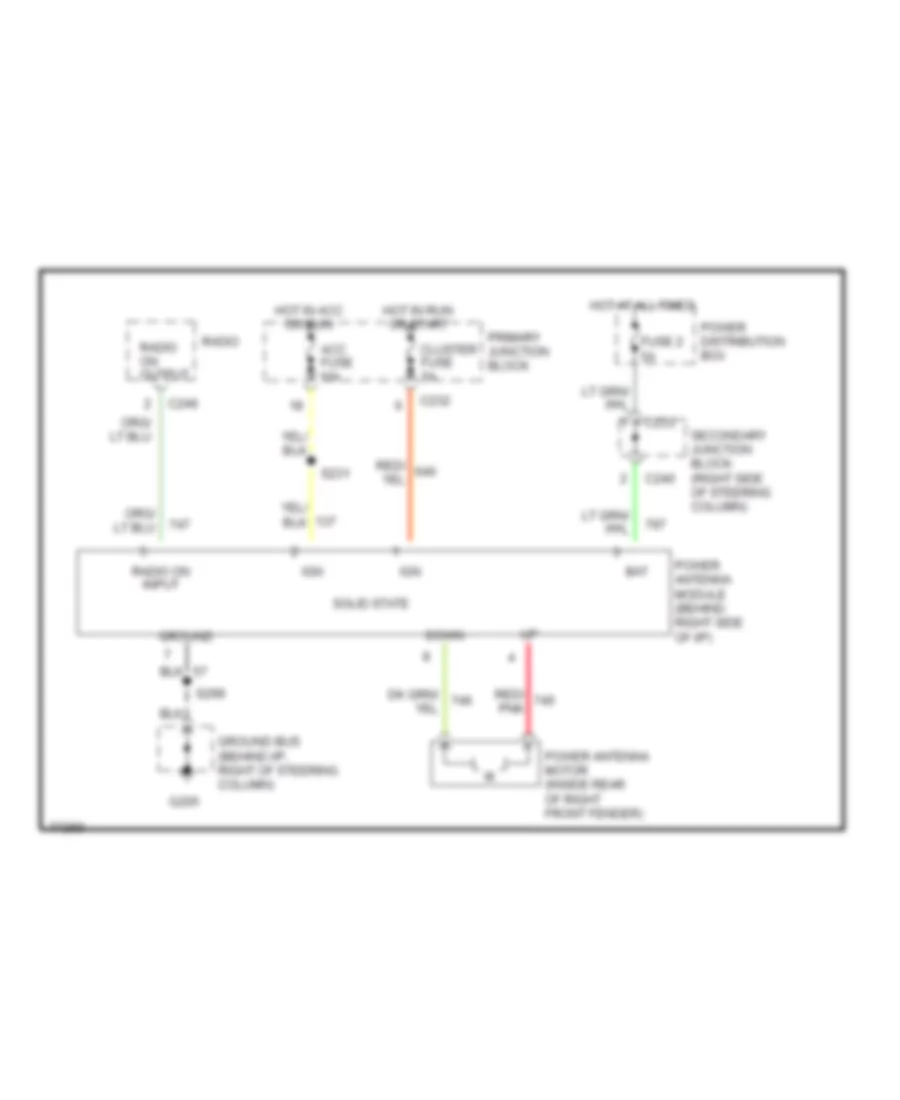
POWER ANTENNA
Power Antenna Wiring Diagram for Mercury Cougar XR7 1996
 https://portal-diagnostov.com/license.html
Automotive Electricians Portal FZCO
Automotive Electricians Portal FZCO
https://portal-diagnostov.com/license.html
https://portal-diagnostov.com/license.html
Automotive Electricians Portal FZCO
Automotive Electricians Portal FZCOList of elements for Power Antenna Wiring Diagram for Mercury Cougar XR7 1996:
- Acc fuse 10a
- Bat
- C232
- C233
- C240
- C246
- Cluster fuse 5a
- Down
- Fuse 2 5a
- G205
- Ground
- Ground bus (behind i/p, right of steering column)
- Hot at all times
- Hot in acc or run
- Hot in run or start
- Ign
- Power antenna module (behind right side of i/p)
- Power antenna motor (inside rear of right front fender)
- Power distribution box
- Primary junction block
- Radio
- Radio on input
- Radio on output
- Red/ pnk
- S231
- S299
- Secondary junction block (right side of steering column)
- Solid state
POWER DISTRIBUTION
Power Distribution Wiring Diagram (1 of 3) for Mercury Cougar XR7 1996
 https://portal-diagnostov.com/license.html
Automotive Electricians Portal FZCO
Automotive Electricians Portal FZCO
https://portal-diagnostov.com/license.html
https://portal-diagnostov.com/license.html
Automotive Electricians Portal FZCO
Automotive Electricians Portal FZCOList of elements for Power Distribution Wiring Diagram (1 of 3) for Mercury Cougar XR7 1996:
- (behind i/p, right side of steering column)
- (not used)
- (not used) (left rear of vehicle, in trunk)
- 20a
- Anti- lock brake control module
- Anti- lock power relay (power distribution box)
- Anti- theft in-line fuse
- Anti-lock pump motor relay
- Anti-theft controller module
- Battery
- Brake on/off (boo) switch
- Brake travel switch
- C206
- C208
- C226
- C232
- C233
- C240
- C245
- C298
- C420
- Cigar lighter
- Cigar ltr fuse 20a
- Constant control relay module (ccrm)
- Data link connector
- Daytime running lamps (drl) module
- Digital clock
- Driver's seat control switch
- Fuse
- Fuse 15a
- Fuse 20a
- Fuse 40a
- Fuse 5a
- Fuse 60a
- G2o5
- Generator/ voltage regulator
- Ground bus
- Horn relay (power distri- bution box)
- Left door lock switch
- Main light switch
- Mega fuse 175a
- Multi-function switch
- Nca
- Obd ii fuse 10a
- Passenger's seat control switch
- Power antenna module
- Power distribution box
- Powertrain control module (pcm)
- Primary junction block
- Radio
- Radio amplifier
- Rear window defrost switch
- Red
- Remote/keyless entry module
- Right door lock switch
- Seat/lock circuit breaker 20a
- Secondary junction block
- Semi- automatic temperature control (satc) module
- Starter motor/ solenoid
- Stop/ haz fuse 15a
- Tan/red
- To ignition switch, pins b1, b4 & b5
- To ignition switch, pins b2 & b3
- To primary junction block
- Trunk lid release switch
- W/ premium sound only
Power Distribution Wiring Diagram (2 of 3) for Mercury Cougar XR7 1996
 https://portal-diagnostov.com/license.html
Automotive Electricians Portal FZCO
Automotive Electricians Portal FZCO
https://portal-diagnostov.com/license.html
https://portal-diagnostov.com/license.html
Automotive Electricians Portal FZCO
Automotive Electricians Portal FZCOList of elements for Power Distribution Wiring Diagram (2 of 3) for Mercury Cougar XR7 1996:
- (not used)
- (not used) (left rear of vehicle, in trunk)
- 3.8l
- 4.6l
- A/c- heater function selector sw
- Acc
- Acc fuse 10a
- Anti- theft controller module
- Blower in-line fuse 30a
- Blower motor speed controller
- C226
- C232
- C233
- C237
- C240
- C250
- C251
- C298
- C420
- Cluster fuse 5a
- Constant control relay module (ccrm)
- Digital clock
- Distribution box)
- Driver's right power window switch
- From fuse 17 (power c
- From fuse 9 (power b
- Fuse 20a
- Gnd
- Ignition coil
- Ignition switch
- Instrument cluster
- Instrument cluster system
- Integrated control module
- Left door lock switch
- Left ignition coil
- Left power window switch
- Left radio noise capacitor
- Light sensor/ amplifier
- Lock
- Moonroof switch assembly
- Nca
- Off
- Power antenna module
- Power distribution box
- Power wdo circuit breaker 20a
- Primary junction block
- Radio
- Radio noise capacitor
- Remote/ keyless entry module
- Right door lock switch
- Right ignition coil
- Right power window switch
- Right radio noise capacitor
- Run
- Secondary junction block
- Speed control amplifier
- Sta
- Start
- To a/c fuse (primary junction block)
- Transmission range (tr) sensor
- W/o satc
- W/satc
- Windshield wiper motor
- Wipers fuse 30a
Power Distribution Wiring Diagram (3 of 3) for Mercury Cougar XR7 1996
 https://portal-diagnostov.com/license.html
Automotive Electricians Portal FZCO
Automotive Electricians Portal FZCO
https://portal-diagnostov.com/license.html
https://portal-diagnostov.com/license.html
Automotive Electricians Portal FZCO
Automotive Electricians Portal FZCOList of elements for Power Distribution Wiring Diagram (3 of 3) for Mercury Cougar XR7 1996:
- (not used)
- (not used) (behind left cowl panel)
- A/c fuse 10a
- A/c- heater function selector switch
- Air bag diagnostic monitor
- Air bags fuse 10a
- Anti-lock brake control module
- Anti-lock fuse 10a
- Anti-lock power relay (power distri- bution box)
- Autolamp dual coil relay
- Blend door motor control
- C2007
- C215
- C226
- C232
- C233
- C236
- C238
- C240
- C243
- C251
- C295
- C298
- C456
- C457
- Daytime running lamps (drl) module
- Distribution box)
- Dome/ map lamps
- Electronic variable orifice (evo) module
- Engine coolant level sensor
- Evo test connector
- Exterior & interior lights systems
- From fuse 7 (power g
- From ignition switch, pin a4
- Indicator lamp module
- Instrument cluster
- Int lps fuse 10a
- Integrated control module
- J/c #1
- Left door courtesy lamp switch
- Left vanity lamp
- Luggage compt lamp
- Main light switch head
- Multi- function switch
- Nca
- Off
- Outside/ recirculate solenoid
- Panel dimmer switch
- Panel lps fuse 5a
- Park
- Park lps fuse 10a
- Power mirror switch
- Primary junction block
- Rear window defrost switch
- Remote/keyless entry module
- Right door courtesy lamp switch
- Right vanity lamp
- Run fuse 5a
- Secondary junction block
- Semi- automatic temperature control (satc) module
- Semi-automatic temperature control (satc) module
- Shift lock actuator
- Spare fuse
- Steering wheel rotation sensor
- Transmission control switch (tcs)
- Transmission range (tr) sensor
- Turn signal fuse 10a
- W/ moonroof only
- W/ power lock
- W/ satc
- W/o power lock
- W/o rke only
- W/o satc
- Washer fluid level sensor
POWER DOOR LOCKS
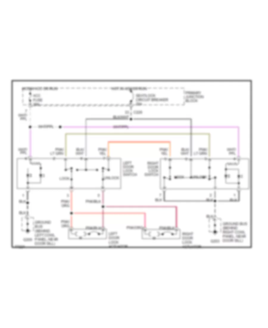
Door Lock Wiring Diagram for Mercury Cougar XR7 1996
 https://portal-diagnostov.com/license.html
Automotive Electricians Portal FZCO
Automotive Electricians Portal FZCO
https://portal-diagnostov.com/license.html
https://portal-diagnostov.com/license.html
Automotive Electricians Portal FZCO
Automotive Electricians Portal FZCOList of elements for Door Lock Wiring Diagram for Mercury Cougar XR7 1996:
- Acc fuse 10a
- C226
- G200
- G203
- Ground bus (behind left cowl panel, near door sill)
- Ground bus (behind right cowl panel, near door sill)
- Hot in acc or run
- Left door lock actuator
- Left door lock switch
- Lock
- Primary junction block
- Right door lock actuator
- Right door lock switch
- Seat/lock circuit breaker 20a
- Unlock
Keyless Entry Wiring Diagram for Mercury Cougar XR7 1996
 https://portal-diagnostov.com/license.html
Automotive Electricians Portal FZCO
Automotive Electricians Portal FZCO
https://portal-diagnostov.com/license.html
https://portal-diagnostov.com/license.html
Automotive Electricians Portal FZCO
Automotive Electricians Portal FZCOList of elements for Keyless Entry Wiring Diagram for Mercury Cougar XR7 1996:
- (behind left cowl panel, near front door sill)
- (behind right cowl panel, near front door sill)
- 1/2 in
- 3/4 in
- 5/6 in
- 7/8 in
- 9/0 in
- A w/ anti-theft system
- Acc fuse 10a
- Antenna
- Anti-theft controller module (left side of trunk, behind whell well)
- Anti-theft system (anti-theft controller module)
- B w/o anti-theft system
- Batt+
- Batt+ save in
- Batt+ save out
- C226
- C232
- C408
- C409
- C455
- C456
- C457
- Ctsy lps out
- Ctsy/dr sw in
- Door ajar in
- Dr handle in
- Exterior lights system
- G200
- G203
- Gnd
- Ground bus
- Ground bus (behind left cowl panel, near front door sill)
- Horn output
- Horn relay
- Hot at all times
- Hot in acc or run
- Hot in run
- Ign
- Int lps fuse 10a
- Interior lights system
- Keypad comm
- Lamp out
- Left door courtesy lamp switch
- Left door latch switch (top rear of left door)
- Left door lock actuator
- Left door lock switch
- Lk drs out
- Lk in
- Lock
- Lock door
- Not used
- Panel dimmer switch
- Park lps out
- Pnk
- Primary junction block
- Program a
- Program b
- Red
- Remote keyless entry module programmer connector (left side of trunk, above wheel well)
- Remote/keyless entry module (left side of trunk, above wheel well)
- Reverse in
- Right door courtesy lamp switch
- Right door latch switch (top rear of right door)
- Right door lock actuator
- Right door lock switch
- Seat sw in
- Seat/lock circuit breaker 20a
- Sig batt+
- Sig gnd
- Trans- mission range (tr) sensor (left rear of transmission)
- Transmitter in
- Trnk lid out
- Trnk lp out
- Trunk lid release solenoid
- Trunk lid release switch
- Turn signal fuse 10a
- Unlk in
- Unlk lt dr out
- Unlk rt dr out
- Unlock
- Unlock door
- Unlock driver's door
POWER MIRRORS
Power Mirror Wiring Diagram for Mercury Cougar XR7 1996
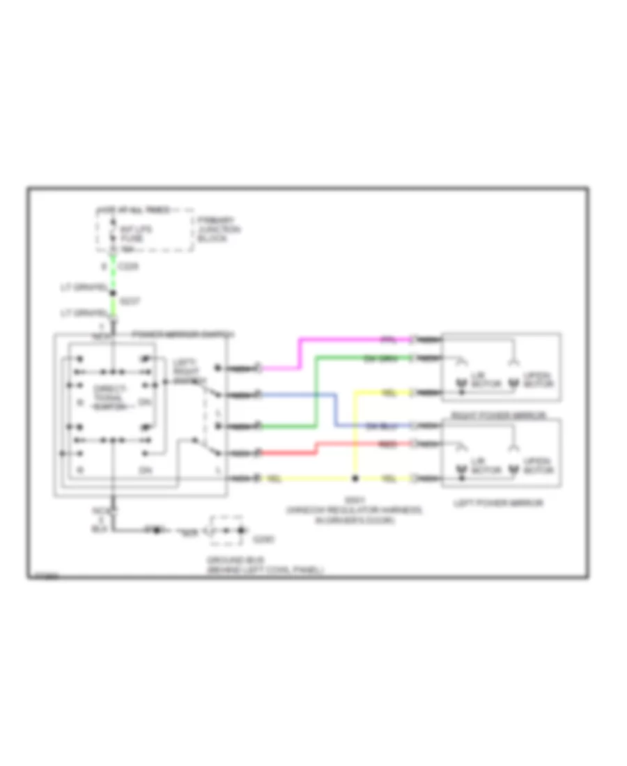 https://portal-diagnostov.com/license.html
Automotive Electricians Portal FZCO
Automotive Electricians Portal FZCO
https://portal-diagnostov.com/license.html
https://portal-diagnostov.com/license.html
Automotive Electricians Portal FZCO
Automotive Electricians Portal FZCOList of elements for Power Mirror Wiring Diagram for Mercury Cougar XR7 1996:
- C226
- Direct- tional switch
- G20o
- Ground bus (behind left cowl panel)
- Hot at all times
- Int lps fuse 10a
- L/r motor
- Left power mirror
- Left/ right switch
- Nca
- Power mirror switch
- Primary junction block
- Right power mirror
- S237
- S501 (window regulator harness, in driver's door)
- S502
- Up/dn motor
POWER SEATS
Power Seat Wiring Diagram for Mercury Cougar XR7 1996
 https://portal-diagnostov.com/license.html
Automotive Electricians Portal FZCO
Automotive Electricians Portal FZCO
https://portal-diagnostov.com/license.html
https://portal-diagnostov.com/license.html
Automotive Electricians Portal FZCO
Automotive Electricians Portal FZCOList of elements for Power Seat Wiring Diagram for Mercury Cougar XR7 1996:
- C226
- Driver's seat control switch
- Driver's seat motor assembly
- Entire seat
- Front height motor
- Front of seat
- Fwd
- Fwd/ rwd motor
- G200
- G203
- Ground bus (behind left cowl panel, near front door sill)
- Ground bus (behind right cowl panel, near front door sill)
- Hot at all times
- Nca
- Passenger's seat control switch
- Passenger's seat motor assembly
- Primary junction block
- Rear height motor
- Rear of seat
- Rwd
- Seat/lock circuit breaker 20a
POWER TOP/SUNROOF
Power Top/Sunroof Wiring Diagrams for Mercury Cougar XR7 1996
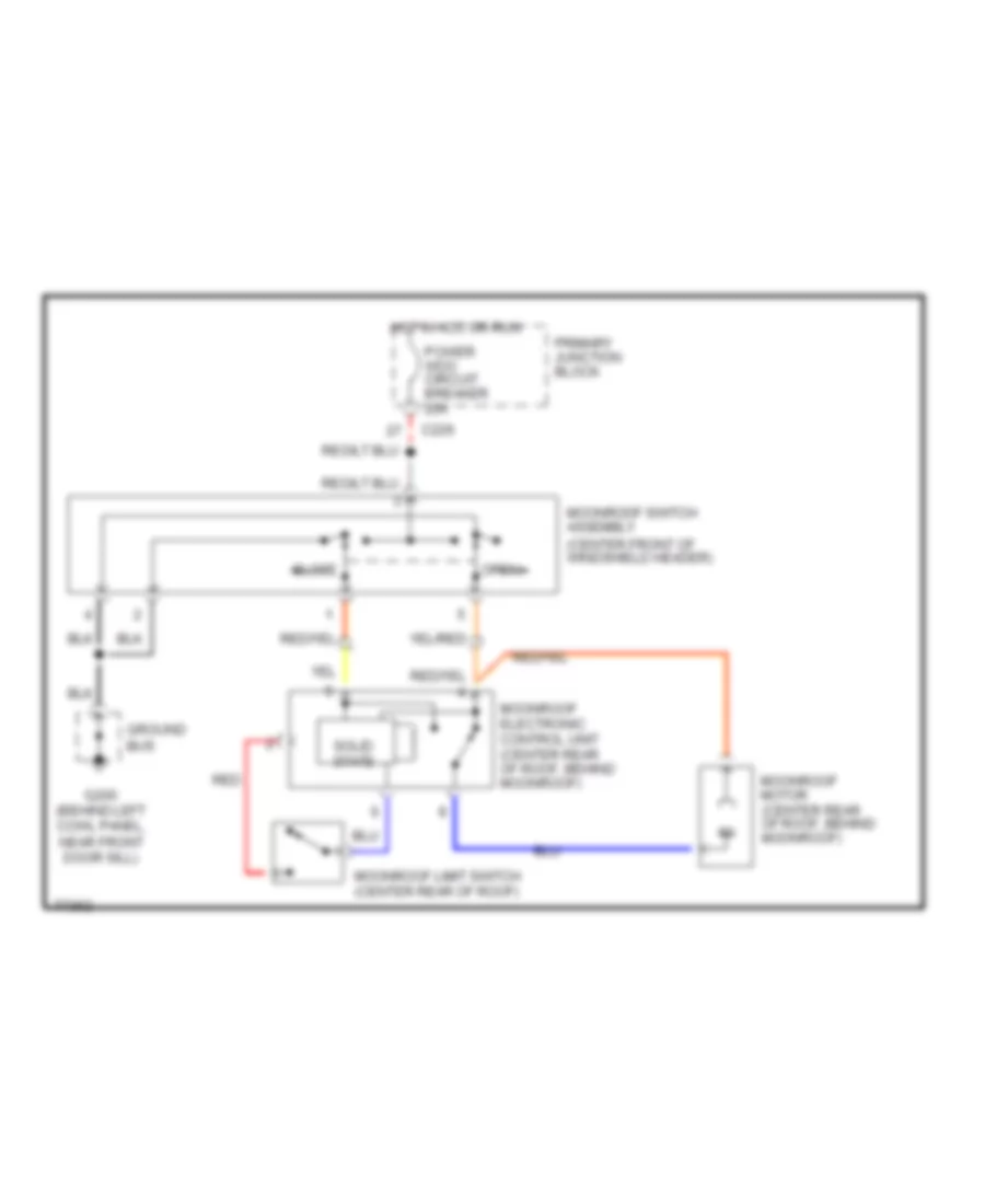 https://portal-diagnostov.com/license.html
Automotive Electricians Portal FZCO
Automotive Electricians Portal FZCO
https://portal-diagnostov.com/license.html
https://portal-diagnostov.com/license.html
Automotive Electricians Portal FZCO
Automotive Electricians Portal FZCOList of elements for Power Top/Sunroof Wiring Diagrams for Mercury Cougar XR7 1996:
- (center front of windshield header)
- C226
- Close
- G200 (behind left cowl panel, near front door sill)
- Ground bus
- Hot in acc or run
- Moonroof electronic control unit (center rear of roof, behind moonroof)
- Moonroof limit switch (center rear of roof)
- Moonroof motor (center rear of roof, behind moonroof)
- Moonroof switch assembly
- Open
- Power wdo circuit breaker 20a
- Primary junction block
- Red
- Solid state
POWER WINDOWS
Power Window Wiring Diagram for Mercury Cougar XR7 1996
 https://portal-diagnostov.com/license.html
Automotive Electricians Portal FZCO
Automotive Electricians Portal FZCO
https://portal-diagnostov.com/license.html
https://portal-diagnostov.com/license.html
Automotive Electricians Portal FZCO
Automotive Electricians Portal FZCOList of elements for Power Window Wiring Diagram for Mercury Cougar XR7 1996:
- Acc fuse 10a
- C226
- Driver's right power window switch
- G200
- G203
- Ground bus (behind left cowl panel, near front door sill)
- Ground bus (behind right cowl panel)
- Hot in acc or run
- Left power window motor
- Left power window switch
- Power wdo circuit breaker 20a
- Primary junction block
- Right power window motor
- Right power window switch
- Up down
RADIO
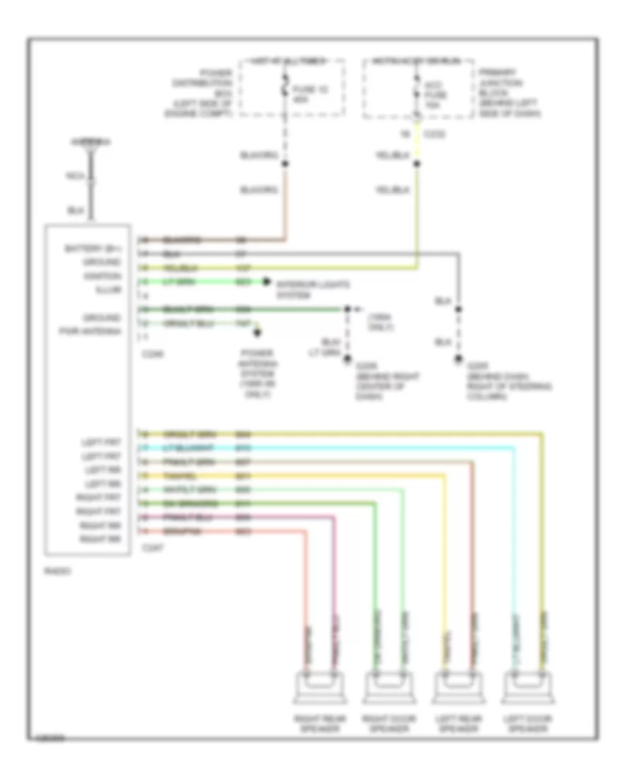
Base Radio for Mercury Cougar XR7 1996
 https://portal-diagnostov.com/license.html
Automotive Electricians Portal FZCO
Automotive Electricians Portal FZCO
https://portal-diagnostov.com/license.html
https://portal-diagnostov.com/license.html
Automotive Electricians Portal FZCO
Automotive Electricians Portal FZCOList of elements for Base Radio for Mercury Cougar XR7 1996:
- (1994 only)
- Acc fuse 10a
- Antenna
- Battery (b+)
- C232
- C246
- C247
- Fuse 12 40a
- G205 (behind dash, right of steering column)
- G206 (behind right center of dash)
- Ground
- Hot at all times
- Hot in accy or run
- Ignition
- Illum
- Interior lights system
- Left door speaker
- Left frt
- Left rear speaker
- Left rr
- Nca
- Power antenna system (1995-96 only)
- Power distribution box (left side of engine compt)
- Primary junction block (behind left side of dash)
- Pwr antenna
- Radio
- Right door speaker
- Right frt
- Right rear speaker
- Right rr
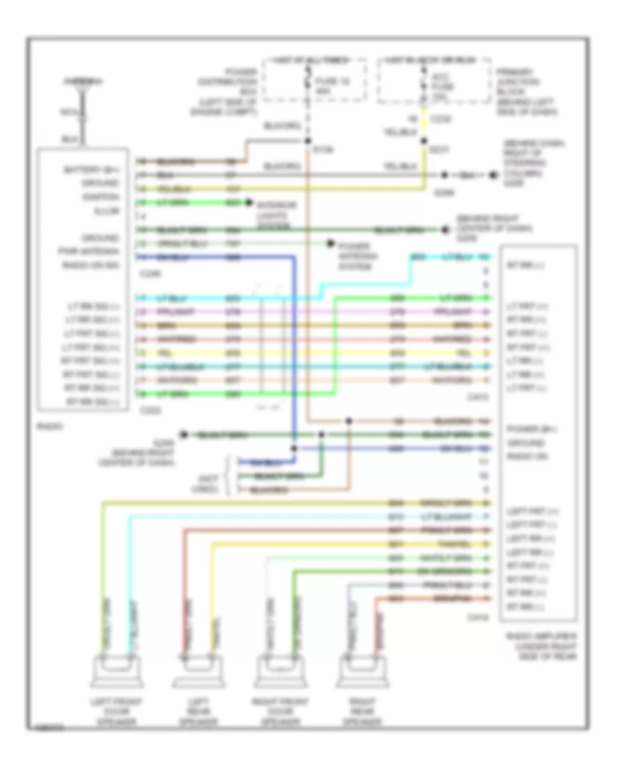
Premium Sound Radio Wiring Diagram for Mercury Cougar XR7 1996
 https://portal-diagnostov.com/license.html
Automotive Electricians Portal FZCO
Automotive Electricians Portal FZCO
https://portal-diagnostov.com/license.html
https://portal-diagnostov.com/license.html
Automotive Electricians Portal FZCO
Automotive Electricians Portal FZCOList of elements for Premium Sound Radio Wiring Diagram for Mercury Cougar XR7 1996:
- (behind dash, right of steering column) g205
- (behind right center of dash) g206
- (not used)
- Acc fuse 10a
- Antenna
- Battery (b+)
- C222
- C232
- C246
- C413
- C414
- Fuse 12 40a
- G206 (behind right center of dash)
- Ground
- Hot at all times
- Hot in accy or run
- Ignition
- Illum
- Interior lights system
- Left front door speaker
- Left frt (+)
- Left frt (-)
- Left rear speaker
- Left rr (+)
- Left rr (-)
- Lt frt (+)
- Lt frt (-)
- Lt frt sig (+)
- Lt frt sig (-)
- Lt rr (+)
- Lt rr (-)
- Lt rr sig (+)
- Lt rr sig (-)
- Nca
- Power (b+)
- Power antenna system
- Power distribution box (left side of engine compt)
- Primary junction block (behind left side of dash)
- Pwr antenna
- Radio
- Radio amplifier (under right side of rear
- Radio on
- Radio on sig
- Right front door speaker
- Right rear speaker
- Rt frt (+)
- Rt frt (-)
- Rt frt sig (+)
- Rt frt sig (-)
- Rt rr (+)
- Rt rr (-)
- Rt rr sig (+)
- Rt rr sig (-)
- S138
- S231
- S299
SHIFT INTERLOCKS
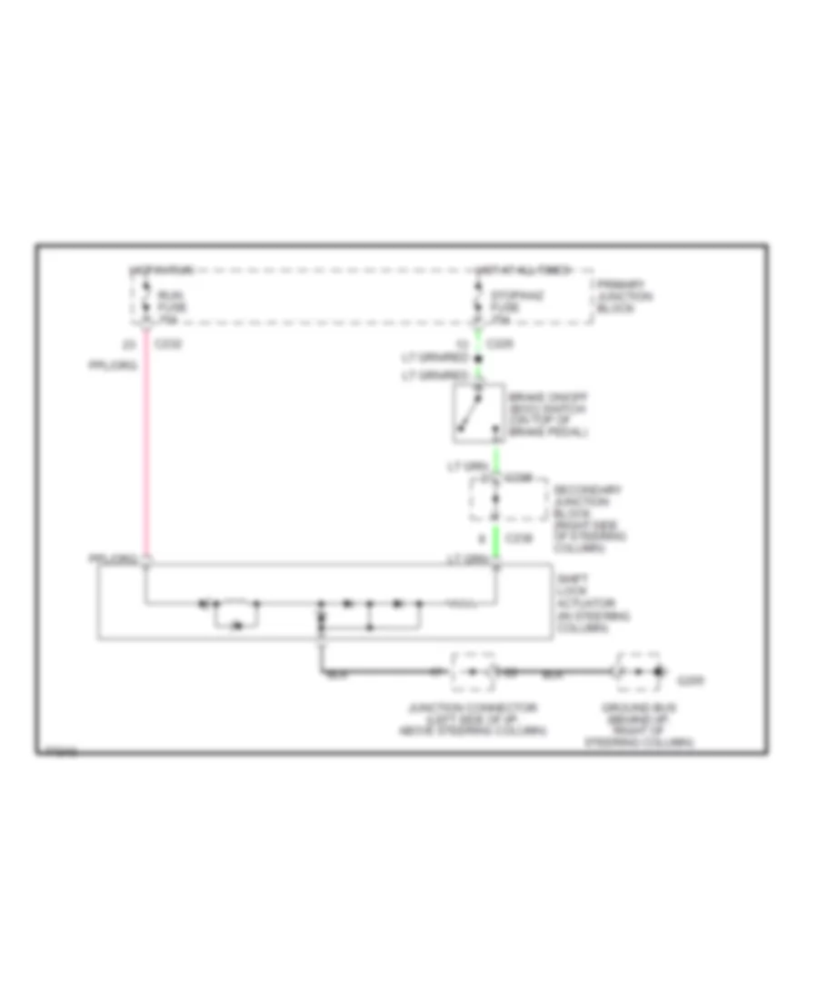
Shift Interlock Wiring Diagram for Mercury Cougar XR7 1996
 https://portal-diagnostov.com/license.html
Automotive Electricians Portal FZCO
Automotive Electricians Portal FZCO
https://portal-diagnostov.com/license.html
https://portal-diagnostov.com/license.html
Automotive Electricians Portal FZCO
Automotive Electricians Portal FZCOList of elements for Shift Interlock Wiring Diagram for Mercury Cougar XR7 1996:
- Brake on/off (boo) switch (on top of brake pedal)
- C226
- C232
- C238
- G205
- Ground bus (behind i/p, right of steering column)
- Hot at all times
- Hot in run
- Junction connector (left side of i/p, above steering column)
- Primary junction block
- Run fuse 15a
- Secondary junction block (right side of steering column)
- Shift lock actuator (in steering column)
- Stop/haz fuse 15a
STARTING/CHARGING
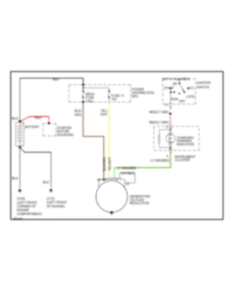
Charging Wiring Diagram for Mercury Cougar XR7 1996
 https://portal-diagnostov.com/license.html
Automotive Electricians Portal FZCO
Automotive Electricians Portal FZCO
https://portal-diagnostov.com/license.html
https://portal-diagnostov.com/license.html
Automotive Electricians Portal FZCO
Automotive Electricians Portal FZCOList of elements for Charging Wiring Diagram for Mercury Cougar XR7 1996:
- Acc
- Battery
- Charging warning indicator
- Fuse 11 15a
- G100 (left front corner of engine compartment)
- G110 (left front of engine)
- Generator/ voltage regulator
- Hot at all times
- Ignition
- Instrument cluster
- Lock
- Mega fuse 175a
- Off
- Power distribution box
- Red
- Run
- Start
- Starter motor/ solenoid
- Switch
Starting Wiring Diagram for Mercury Cougar XR7 1996
 https://portal-diagnostov.com/license.html
Automotive Electricians Portal FZCO
Automotive Electricians Portal FZCO
https://portal-diagnostov.com/license.html
https://portal-diagnostov.com/license.html
Automotive Electricians Portal FZCO
Automotive Electricians Portal FZCOList of elements for Starting Wiring Diagram for Mercury Cougar XR7 1996:
- (left front corner of engine compartment)
- Acc
- Anti-theft controller module (left side of trunk, behind wheel well)
- Anti-theft jumper (used when anti-theft is not installed)
- Battery
- Fuse 9 60a
- G100
- G110 (left front of engine)
- Hold
- Ignition switch
- Lock
- Off
- Pnk
- Power distribution box
- Pull-in
- Red
- Red/
- Run
- Sta
- Start
- Starter interrupt relay (behind left i/p)
- Starter motor/ solenoid (lower right rear of engine)
- Transmission range (tr) sensor (left rear of transmission)
- W/ anti-theft provisions
- W/o anti-theft provisions
SUPPLEMENTAL RESTRAINTS
Supplemental Restraint Wiring Diagram for Mercury Cougar XR7 1996
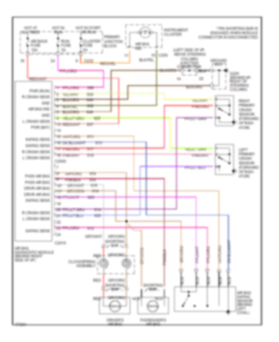 https://portal-diagnostov.com/license.html
Automotive Electricians Portal FZCO
Automotive Electricians Portal FZCO
https://portal-diagnostov.com/license.html
https://portal-diagnostov.com/license.html
Automotive Electricians Portal FZCO
Automotive Electricians Portal FZCOList of elements for Supplemental Restraint Wiring Diagram for Mercury Cougar XR7 1996:
- (left side of i/p, above steering column) junction connector
- * pin shorting bar is engaged when module connector is disconnected
- 10*
- 11*
- Air bag diagnostic module (behind right side of i/p)
- Air bag ind
- Air bag safing sensor (behind left cowl)
- Air bags fuse 10a
- C2000
- C2015
- C232
- Clockspring assembly
- Cluster fuse 5a
- Driver's air bag
- Drvr air bag
- G205 (behind i/p, right of steering column)
- Gnd
- Ground bus
- Hot at all times
- Hot in run
- Hot in start or run
- Instrument cluster
- L crash sens
- Left primary crash sensor (forward of radi- ator)
- Nca
- Pass air bag
- Passenger's air bag
- Primary junction block
- Pwr (bat)
- Pwr (run)
- R crash sens
- Red
- Right primary crash sensor (forward of radi- ator)
- Run fuse 5a
- Safing sens
- Shorting bar
TRANSMISSION
3.8L
3.8L, Transmission Wiring Diagram for Mercury Cougar XR7 1996
 https://portal-diagnostov.com/license.html
Automotive Electricians Portal FZCO
Automotive Electricians Portal FZCO
https://portal-diagnostov.com/license.html
https://portal-diagnostov.com/license.html
Automotive Electricians Portal FZCO
Automotive Electricians Portal FZCOList of elements for 3.8L, Transmission Wiring Diagram for Mercury Cougar XR7 1996:
- (behind power steering reservoir) powertrain control module (pcm)
- (fuel charge harness, in break out to in line connector in rear of engine compartment) s111
- (in engine control harness, near break out to constant control relay module)
- (in engine control sensor harness near break out to in line connector behind right side)
- (in transmission control selector neutral switch harness, near break out to transmission s136
- (in transmission control selector neutral switch harness, near break out to vss) s128
- (right front of engine compartment, on upper radiator support)
- 4r70w transmission
- 91s
- A/c cut out sw
- Boo switch input
- Brake on/off (boo) switch (near top of brake pedal)
- Cluster fuse 15a
- Constant control relay module
- Data link +
- Data link -
- Data link power
- Elect press cntrl
- Electronic pressure control (epc) solenoid
- Engine coolant temperature (ect) sensor (upper left side of engine)
- Fuse 20a
- G109 (right front of engine compartment, on upper radiator support)
- G111 (under battery)
- Hot at all times
- Hot in run
- Hot in run or start
- Ignition power
- Instrument cluster
- Intake air temp
- Intake air temperature (iat) sensor (left rear of engine compartment)
- Interior fuse panel
- Maf return
- Maf sensor sig
- Mass air flow (maf) sensor (left rear of engine compartment)
- Output shaft speed (oss) sensor (lower left rear of engine compartment)
- Pcm data link connector 1 (partial) (left rear coner of engine compartment)
- Pcm power relay
- Power distribution box (left side of engine compartment)
- Primary junction block
- Red
- Red red
- Ref votage
- Run fuse 5a
- S124
- S125
- S170
- S179
- S204
- S211
- S223 (in main harness, near break out to right i/p lamp)
- S269 (in engine control sensor harness, behind right side of i/p)
- S283
- Seccondary junction block (right side of steering column)
- Shift sol 1
- Shift solenoid 2
- Shift solenoids
- Signal control
- Ss1
- Ss2
- Stop/ haz fuse 15a
- Tci lamp
- Temp sens
- Throttle position (tp) sensor (on throttle body)
- To a/c system
- Torque conv sol
- Torque converter clutch (tcc) solenoid
- Tps signal
- Tr sens/pnp sw
- Trans cntrl sw
- Trans control indicator lamp
- Trans temp
- Transmission control switch (tcs) (below front of console)
- Transmission fluid temperature sensor
- Transmission range (tr) sensor (left side of engine compartment)
- Turbine shaft sig
- Vehicle speed sensor (vss) (lower rear of transaxle)
- Vss (-)
- Vss signal
4.6L
4.6L, Transmission Wiring Diagram for Mercury Cougar XR7 1996
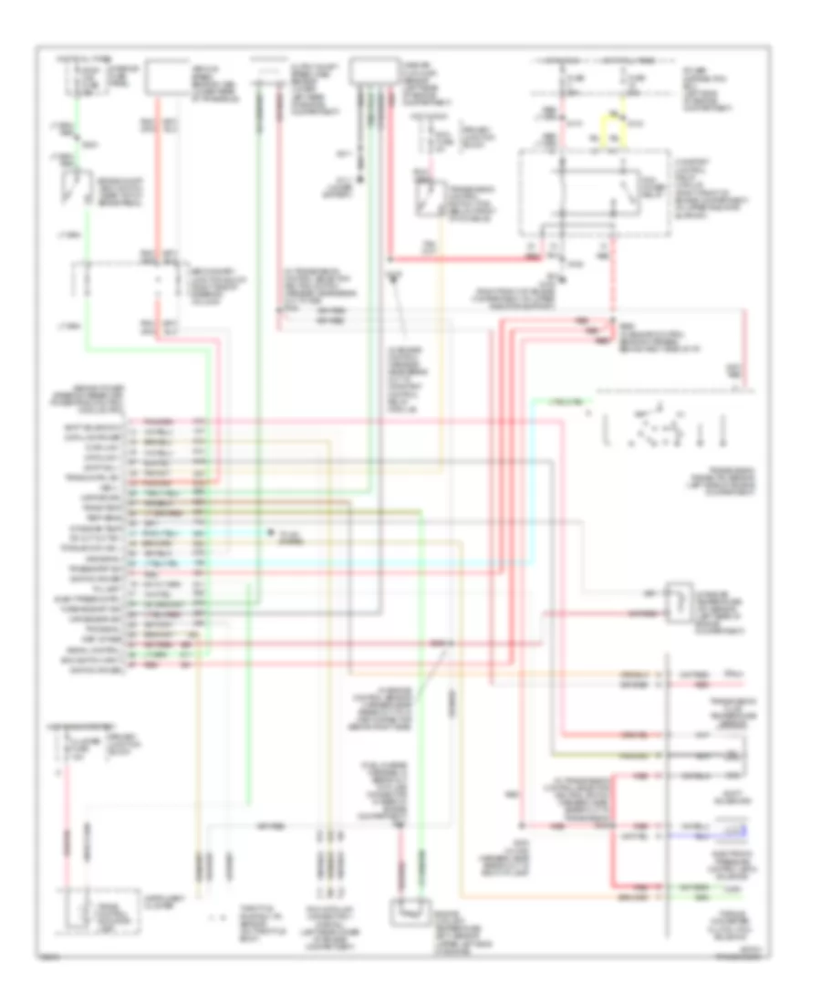 https://portal-diagnostov.com/license.html
Automotive Electricians Portal FZCO
Automotive Electricians Portal FZCO
https://portal-diagnostov.com/license.html
https://portal-diagnostov.com/license.html
Automotive Electricians Portal FZCO
Automotive Electricians Portal FZCOList of elements for 4.6L, Transmission Wiring Diagram for Mercury Cougar XR7 1996:
- (behind power steering reservoir) powertrain control module (pcm)
- (fuel charge harness, in break out to in line connector in rear of engine compartment) s111
- (in engine control harness, near break out to constant control relay module)
- (in engine control sensor harness near break out to in line connector behind right side)
- (in transmission control selector neutral switch harness, near break out to transmission s136
- (in transmission control selector neutral switch harness, near break out to vss) s128
- (right front of engine compartment, on upper radiator support)
- 4r70w transmission
- 91s
- A/c cut out sw
- Boo switch input
- Brake on/off (boo) switch (near top of brake pedal)
- Cluster fuse 15a
- Constant control relay module
- Data link +
- Data link -
- Data link power
- Elect press cntrl
- Electronic pressure control (epc) solenoid
- Engine coolant temperature (ect) sensor (upper left side of engine)
- Fuse 20a
- G109 (right front of engine compartment, on upper radiator support)
- G111 (under battery)
- Hot at all times
- Hot in run
- Hot in run or start
- Ignition power
- Instrument cluster
- Intake air temp
- Intake air temperature (iat) sensor (left rear of engine compartment)
- Interior fuse panel
- Maf return
- Maf sensor sig
- Mass air flow (maf) sensor (left rear of engine compartment)
- Output shaft speed (oss) sensor (lower left rear of engine compartment)
- Pcm data link connector 1 (partial) (left rear coner of engine compartment)
- Pcm power relay
- Power distribution box (left side of engine compartment)
- Primary junction block
- Red
- Red red
- Ref votage
- Run fuse 5a
- S124
- S125
- S170
- S179
- S204
- S211
- S223 (in main harness, near break out to right i/p lamp)
- S269 (in engine control sensor harness, behind right side of i/p)
- S283
- Seccondary junction block (right side of steering column)
- Shift sol 1
- Shift solenoid 2
- Shift solenoids
- Signal control
- Ss1
- Ss2
- Stop/ haz fuse 15a
- Tci lamp
- Temp sens
- Throttle position (tp) sensor (on throttle body)
- To a/c system
- Torque conv sol
- Torque converter clutch (tcc) solenoid
- Tps signal
- Tr sens/pnp sw
- Trans cntrl sw
- Trans control indicator lamp
- Trans temp
- Transmission control switch (tcs) (below front of console)
- Transmission fluid temperature sensor
- Transmission range (tr) sensor (left side of engine compartment)
- Turbine shaft sig
- Vehicle speed sensor (vss) (lower rear of transaxle)
- Vss (-)
- Vss signal
TRUNK, TAILGATE, FUEL DOOR
Trunk Release Wiring Diagram for Mercury Cougar XR7 1996
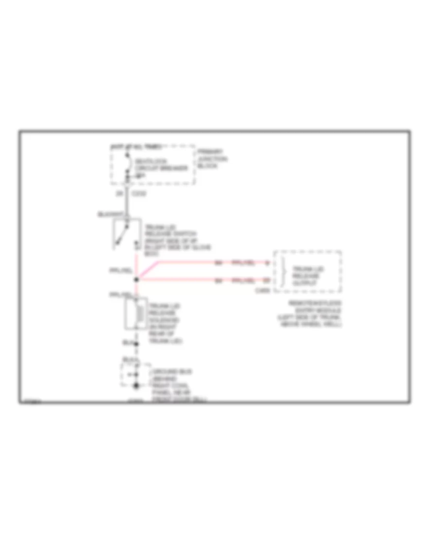 https://portal-diagnostov.com/license.html
Automotive Electricians Portal FZCO
Automotive Electricians Portal FZCO
https://portal-diagnostov.com/license.html
https://portal-diagnostov.com/license.html
Automotive Electricians Portal FZCO
Automotive Electricians Portal FZCOList of elements for Trunk Release Wiring Diagram for Mercury Cougar XR7 1996:
- C232
- C456
- G203
- Ground bus (behind right cowl panel, near front door sill)
- Hot at all times
- Primary junction block
- Remote/keyless entry module (left side of trunk, above wheel well)
- Seat/lock circuit breaker 20a
- Trunk lid release output
- Trunk lid release solenoid (in right rear of trunk lid)
- Trunk lid release switch (right side of i/p, in left side of glove box)
WARNING SYSTEMS
Warning System Wiring Diagrams for Mercury Cougar XR7 1996
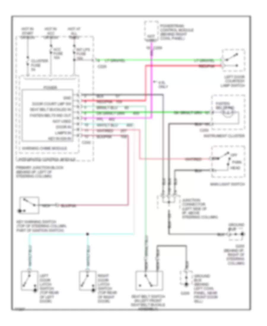 https://portal-diagnostov.com/license.html
Automotive Electricians Portal FZCO
Automotive Electricians Portal FZCO
https://portal-diagnostov.com/license.html
https://portal-diagnostov.com/license.html
Automotive Electricians Portal FZCO
Automotive Electricians Portal FZCOList of elements for Warning System Wiring Diagrams for Mercury Cougar XR7 1996:
- 4.6l only
- Acc fuse 10a
- C226
- C242
- C250
- Cluster fuse 5a
- Door court lmp sw
- Door in
- Fasten belts ind
- Fasten belts ind out
- G200
- G205 (behind i/p, right of steering column)
- Gnd
- Ground bus
- Ground bus (behind left cowl panel, near front door sill)
- Head
- Hot at all times
- Hot in acc or run
- Hot in start or run
- Instrument cluster
- Int lps fuse 10a
- Integrated control module
- Junction connector (left side of i/p, above steering column)
- Key in ign in
- Key warning switch (top of steering column, part of ignition switch)
- Lamps in
- Left door courtesy lamp switch
- Left door latch switch (top rear of left door)
- Main light switch
- Nca
- Not used
- Off
- Park
- Power
- Powertrain control module (behind right cowl panel)
- Primary junction block (behind i/p, left of steering column)
- Red/pnk
- Right door latch switch (top rear of right door)
- Seat belt buckled in
- Seat belt switch (in left front seat belt buckle assembly)
- Warning chime module
WIPER/WASHER
Wiper/Washer Wiring Diagram for Mercury Cougar XR7 1996
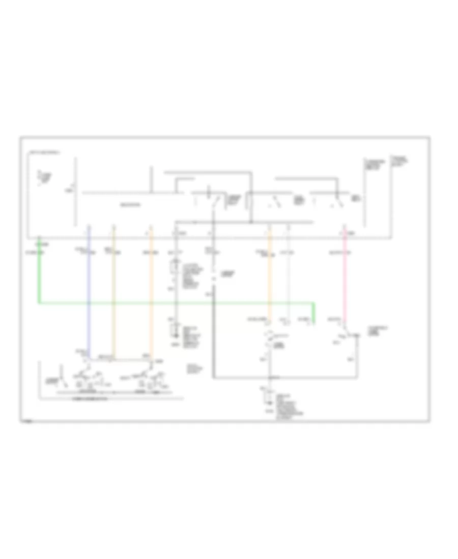 https://portal-diagnostov.com/license.html
Automotive Electricians Portal FZCO
Automotive Electricians Portal FZCO
https://portal-diagnostov.com/license.html
https://portal-diagnostov.com/license.html
Automotive Electricians Portal FZCO
Automotive Electricians Portal FZCOList of elements for Wiper/Washer Wiring Diagram for Mercury Cougar XR7 1996:
- 100k ohms
- 3.3k
- 4.08k
- 7.25k
- C206
- C226
- C242
- C294
- C295
- G108
- G205
- Ground bus (behind i/p, right of steering column)
- Ground bus (left front of vehicle, mounted on upper radiator support)
- Hi/lo speed relay
- Hot in acc or run
- Int max
- Int min
- Integrated control module
- Junction connector (left side of i/p, above steering column)
- Multi- function switch
- Off
- Off 36.27k
- Ohms
- Park
- Park relay
- Primary junction block
- Run
- S144
- Solid state
- Washer motor
- Washer motor relay
- Washer switch
- Windshield wiper motor
- Wiper fuse 30a
- Wiper motor
- Wiper/washer switch

 Čeština
 Dansk
Dansk Deutsch
 Ελληνικά
 English
 English
 Español
 Suomi
Suomi Français
 Français
 עברית
עברית Hrvatski
 Magyar
 Italiano
 한국어
한국어 Nederlands
 Polski
 Português
 Português
 Română
 Русский
 Slovenčina
 Slovenščina
 Svenska
 Türkçe
 中文 (中国)
