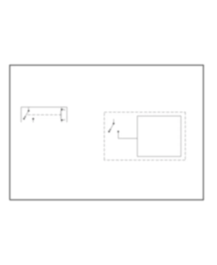
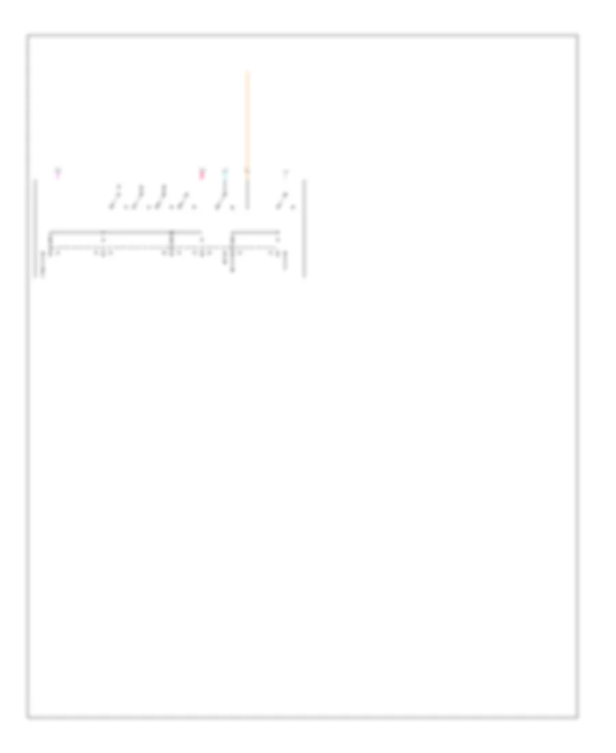
AIR CONDITIONING
Compressor Wiring Diagram for Pontiac Grand Prix GT 2003
 https://portal-diagnostov.com/license.html
Automotive Electricians Portal FZCO
Automotive Electricians Portal FZCO
https://portal-diagnostov.com/license.html
https://portal-diagnostov.com/license.html
Automotive Electricians Portal FZCO
Automotive Electricians Portal FZCO
List of elements for Compressor Wiring Diagram for Pontiac Grand Prix GT 2003:
- (engine harn, 4 cm from c105)
- (on transaxle stud, near starter)
- 5 volt ref
- A/c clu diode
- A/c clu relay
- A/c clu/ abs ign fuse 28 10a
- A/c compressor clutch
- A/c press signal
- A/c refrigerent pressure sensor (left side of engine compt, on accumulator)
- A/c request
- Battery
- C11
- Clutch request
- Comp control
- Dic/hvac fuse 10a
- G117
- G200 (right side of dash cross- beam)
- Gnd
- Hot at all times
- Hot in run
- Hot in run, bulb test or start
- Hvac control module
- I/p fuse block (behind right side of dash)
- Ign 3 volt
- Low ref
- Powertrain control module (left front side of engine compt, in air cleaner assembly)
- Radio fuse 10a
- S105
- S202 (i/p harn, 17 cm from data link connector)
- S213 (i/p harn, 4 cm from blower motor resistors/ control module breakout)
- Underhood fuse block (mounted to right strut tower)
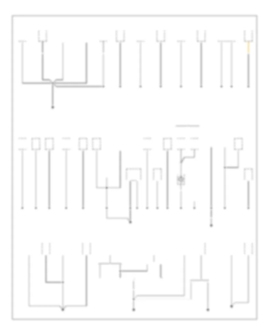
3.1L VIN J
3.1L VIN J, Manual A/C Wiring Diagram for Pontiac Grand Prix GT 2003
 https://portal-diagnostov.com/license.html
Automotive Electricians Portal FZCO
Automotive Electricians Portal FZCO
https://portal-diagnostov.com/license.html
https://portal-diagnostov.com/license.html
Automotive Electricians Portal FZCO
Automotive Electricians Portal FZCOList of elements for 3.1L VIN J, Manual A/C Wiring Diagram for Pontiac Grand Prix GT 2003:
- (engine harn, 4 cm from c105)
- (fuel inj wiring harn)
- (i/p harn, 4 cm from blower motor resistors/ control module breakout)
- (i/p harn, 4 cm from data link breakout) s206
- (left side of hvac module) air temperature actuator (left)
- (right side of dash cross- beam) g200
- +5v reference
- A/c compressor clutch
- A/c clu diode
- A/c clu relay
- A/c clu/ abs ign fuse 28 10a
- A/c press signal
- A/c refrigerent pressure sensor (left side of engine compt, on accumulator)
- A/c request sig
- A10
- Air temperature actuator (right) (right side of hvac module)
- Battery
- Blower motor (in hvac module)
- Blower motor relay
- Blower motor resistor assembly (right side of hvac module)
- C10
- C11
- Clutch request
- Comp control
- Cool fan 1 fuse 6 30a
- Cool fan 2 fuse 1 30a
- Cool fan 1 relay
- Cool fan 2 relay
- Cool fan relay
- Defog rly ctrl
- Defogger system
- Dic/hvac fuse 10a
- Ect signal
- Engine controls system (map sensor)
- Engine coolant temperature (ect) sensor (top left rear of engine, below throttle body)
- F11
- G117 (on transaxle stud, near starter)
- Gnd
- High speed
- Hot at all times
- Hot in run
- Hot in run, bulb test or start
- Hvac control module
- Hvac ctrl fuse 20a
- Hvac hi fuse 30a
- I/p fuse block (behind right side of dash)
- I/p lamp sply volt
- Ign
- Ign 3 volt
- Interior lights system
- Left cooling fan motor
- Lft temp dr ctrl
- Low ref
- Low reference
- Low speed
- Nca
- Nca nca
- Off
- Off blwr mtr ctrl
- P10
- P11
- Park lmp sw on
- Pos
- Powertrain control module (pcm) (left front side of engine compt, in air cleaner assembly)
- R10
- R11
- Radio fuse 10a
- Right cooling fan motor
- Rt temp dr ctrl
- S105
- S121
- S213
- T10
- T11
- Tan
- U11
- Underhood fuse block (mounted to strut tower)
- V10
- V11
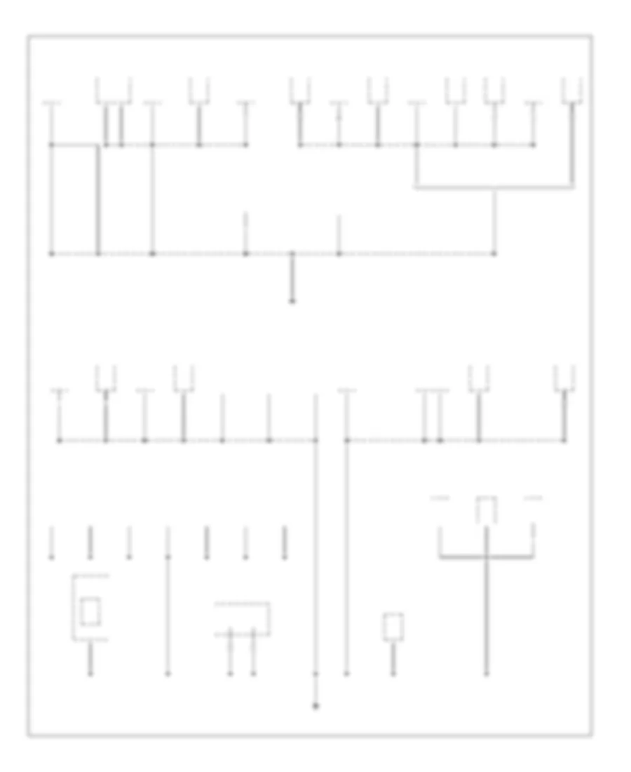
3.8L VIN 1
3.8L VIN 1, Manual A/C Wiring Diagram for Pontiac Grand Prix GT 2003
 https://portal-diagnostov.com/license.html
Automotive Electricians Portal FZCO
Automotive Electricians Portal FZCO
https://portal-diagnostov.com/license.html
https://portal-diagnostov.com/license.html
Automotive Electricians Portal FZCO
Automotive Electricians Portal FZCOList of elements for 3.8L VIN 1, Manual A/C Wiring Diagram for Pontiac Grand Prix GT 2003:
- (engine harn, 4 cm from c105)
- (i/p harn, 4 cm from blower motor resistors/ control module breakout)
- (i/p harn, 4 cm from data link breakout) s206
- (left side of hvac module) air temperature actuator (left)
- (right side of dash cross- beam) g200
- +5v reference
- A/c compressor clutch
- A/c clu diode
- A/c clu relay
- A/c clu/ abs ign fuse 28 10a
- A/c press signal
- A/c refrigerent pressure sensor (left side of engine compt, on accumulator)
- A/c request sig
- A10
- Air temperature actuator (right) (right side of hvac module)
- Battery
- Blower motor (in hvac module)
- Blower motor relay
- Blower motor resistor assembly (right side of hvac module)
- C10
- C11
- Clutch request
- Comp control
- Cool fan 1 fuse 6 30a
- Cool fan 2 fuse 1 30a
- Cool fan 1 relay
- Cool fan 2 relay
- Cool fan relay
- Cooling fan motor (left)
- Cooling fan motor (right)
- Defog rly ctrl
- Defogger system
- Dic/hvac fuse 10a
- Ect signal
- Engine coolant temperature (ect) sensor (top left rear of engine, below throttle body)
- F11
- G117 (on transaxle stud, near starter)
- Gnd
- High speed
- Hot at all times
- Hot in run
- Hot in run, bulb test or start
- Hvac control module
- Hvac ctrl fuse 20a
- Hvac hi fuse 30a
- I/p fuse block (behind right side of dash)
- I/p lamp sply volt
- Ign
- Ign 3 volt
- Interior lights system
- Lft temp dr ctrl
- Low ref
- Low speed
- Nca
- Nca nca
- Off
- Off blwr mtr ctrl
- P10
- P11
- Park lmp sw on
- Pos
- Powertrain control module (pcm) (left front side of engine compt, in air cleaner assembly)
- R10
- R11
- Radio fuse 10a
- Rt temp dr ctrl
- S105
- S213
- T10
- T11
- Tan
- U11
- Underhood fuse block (mounted to strut tower)
- V10
- V11
3.8L VIN K
3.8L VIN K, Manual A/C Wiring Diagram for Pontiac Grand Prix GT 2003
 https://portal-diagnostov.com/license.html
Automotive Electricians Portal FZCO
Automotive Electricians Portal FZCO
https://portal-diagnostov.com/license.html
https://portal-diagnostov.com/license.html
Automotive Electricians Portal FZCO
Automotive Electricians Portal FZCOList of elements for 3.8L VIN K, Manual A/C Wiring Diagram for Pontiac Grand Prix GT 2003:
- (engine harn, 4 cm from c105)
- (i/p harn, 4 cm from blower motor resistors/ control module breakout)
- (i/p harn, 4 cm from data link breakout) s206
- (left side of hvac module) air temperature actuator (left)
- (right side of dash cross- beam) g200
- +5v reference
- A/c compressor clutch
- A/c clu diode
- A/c clu relay
- A/c clu/ abs ign fuse 28 10a
- A/c press signal
- A/c refrigerent pressure sensor (left side of engine compt, on accumulator)
- A/c request sig
- A10
- Air temperature actuator (right) (right side of hvac module)
- Battery
- Blower motor (in hvac module)
- Blower motor relay
- Blower motor resistor assembly (right side of hvac module)
- C10
- C11
- Clutch request
- Comp control
- Cool fan 1 fuse 6 30a
- Cool fan 2 fuse 1 30a
- Cool fan 1 relay
- Cool fan 2 relay
- Cool fan relay
- Cooling fan motor (left)
- Cooling fan motor (right)
- Defog rly ctrl
- Defogger system
- Dic/hvac fuse 10a
- Ect signal
- Engine coolant temperature (ect) sensor (top left rear of engine, below throttle body)
- F11
- G117 (on transaxle stud, near starter)
- Gnd
- High speed
- Hot at all times
- Hot in run
- Hot in run, bulb test or start
- Hvac control module
- Hvac ctrl fuse 20a
- Hvac hi fuse 30a
- I/p fuse block (behind right side of dash)
- I/p lamp sply volt
- Ign
- Ign 3 volt
- Interior lights system
- Lft temp dr ctrl
- Low ref
- Low speed
- Nca
- Nca nca
- Off
- Off blwr mtr ctrl
- P10
- P11
- Park lmp sw on
- Pos
- Powertrain control module (pcm) (left front side of engine compt, in air cleaner assembly)
- R10
- R11
- Radio fuse 10a
- Rt temp dr ctrl
- S105
- S213
- T10
- T11
- Tan
- U11
- Underhood fuse block (mounted to strut tower)
- V10
- V11
ANTI-LOCK BRAKES
Anti-lock Brakes Wiring Diagram for Pontiac Grand Prix GT 2003
 https://portal-diagnostov.com/license.html
Automotive Electricians Portal FZCO
Automotive Electricians Portal FZCO
https://portal-diagnostov.com/license.html
https://portal-diagnostov.com/license.html
Automotive Electricians Portal FZCO
Automotive Electricians Portal FZCOList of elements for Anti-lock Brakes Wiring Diagram for Pontiac Grand Prix GT 2003:
- (eng harn, on left side of eng compt, 4 cm from ebcm breakout)
- (left side of dash, at base of steering column) g205
- A/c clu/ abs ign fuse 10a
- Abs ind
- Battery
- Brake pressure modulator valve
- C 1995 vftc
- Data link connector (dlc) (under left side of dash, right of steering column)
- Driver information center (dic)
- Electronic brake control module (ebcm) (left side of eng compt, part of brake pessure modulator valve0
- Electronic power steering system (magnasteer actuator)
- G119 (left side of eng compt, at base of strut tower)
- G200 (right side of dash cross beam, behind fuse block)
- Ground
- Hot at all times
- Hot in run, bulb test or start
- I/p fuse block (behind right side of dash, in glove box opening)
- Ignition
- Ind ctrl
- Instrument panel cluster
- Ip-ign fuse 10a
- Left front wheel speed sensor
- Left rear wheel speed sensor
- Lf whl spd
- Lo trac ind
- Low trac ind
- Lr whl spd
- Msva high
- Msva low
- Nca
- Pnk
- Powertrain control module (pcm) (left front side of eng compt, in air cleaner assembly)
- Pump motor
- Pump mtr ctrl
- Red
- Req tps sig
- Rf whl spd
- Right front wheel speed sensor
- Right rear wheel speed sensor
- Rr whl spd
- S131
- S205 (i/p harn, below dash, near c201, 14 cm from g201 breakout)
- S209
- S285
- Serial data
- Stop lamp fuse 15a
- Stop lamp switch (on brake pedal support bracket)
- Stop lp feed
- Tach out c2
- Tach signal
- Tan
- Tcs ind
- Tcs signal
- Torque del c2
- Torque req c1
- Trac
- Trac ctrl
- Trac off ind
- Trac switch
- Underhood fuse block
- Underhood fuse block (mounted to right strut tower)
- W/ trip monitor
- W/o trip monitor
ANTI-THEFT
Anti-theft Wiring Diagram for Pontiac Grand Prix GT 2003
 https://portal-diagnostov.com/license.html
Automotive Electricians Portal FZCO
Automotive Electricians Portal FZCO
https://portal-diagnostov.com/license.html
https://portal-diagnostov.com/license.html
Automotive Electricians Portal FZCO
Automotive Electricians Portal FZCOList of elements for Anti-theft Wiring Diagram for Pontiac Grand Prix GT 2003:
- (body harness below front passenger seat 11cm (2 in) from breakout for g302)
- (i/p harn, behind right side of instrument cluster)
- (in air cleaner assembly) powertrain control module
- (left front door sill)
- (right front door sill)
- (right side of dash cross beam, behind fuse block)
- 12v
- Accy 1
- All door unlock
- Battery
- Body control module (behind left side of dash)
- C13
- Computer data lines system
- D10
- D11
- D13
- D14
- D15
- Data
- Door locks system
- Driver door ajar switch
- Driver door lock cylinder switch
- Driver door lock switch
- Driver dr ajar in
- Driver unlock
- E12
- Ecm fuse 10a
- Ext lights out
- Exterior lamps system
- Front passenger door ajar switch
- Front passenger door lock cylinder switch
- Front passenger door lock switch
- Fuel
- Fuel enable control
- G200
- G200 (right side of dash, behind fuse block)
- G301
- G301 (left front door sill)
- G302
- G302 (right front door sill)
- Gnd
- Ground
- Horn relay out
- Horns system
- Hot at all times
- Hot in acc or run
- Hot in run, bulb test or start
- Hvac/rke battery fuse 29 10a
- I/p fuse block
- I/p-ign fuse 10a
- Ign 1
- Ind
- Instrument cluster system (driver information center)
- Instrument panel cluster
- Int lamp fuse 10a
- Interior lights system
- Interior lights system (rear compartment courtesy light)
- Left rear door ajar switch (if equipped)
- Lock
- Lock sw input
- Mall fuse 10a
- Nca
- Pass dr ajar in
- Pass-key fuse 10a
- Pnk
- Power distribution system
- Rear compartment courtesy light switch (on rear compartment lid)
- Rear compt key cyl lock switch
- Rfa link
- Right rear door ajar switch (if equipped)
- S202
- S209
- S273
- S285
- S303
- S308
- S309 (body harn, below right side of front passenger's seat)
- S311
- S406
- S416
- S504
- S604
- Security ind
- Security led
- Tamper input
- Tan
- Theft deterrent control module (part of ignition key cylinder)
- Theft led
- Trunk ajar sw
- Underhood fuse block (mounted to right strut tower)
- Unlock
- Unlock sw input
- Vehicle interface unit (viu) (in trunk, at left rear wheel well)
- W/ on star
- W/o on star
BODY CONTROL MODULES
Body Control Modules Wiring Diagram for Pontiac Grand Prix GT 2003
 https://portal-diagnostov.com/license.html
Automotive Electricians Portal FZCO
Automotive Electricians Portal FZCO
https://portal-diagnostov.com/license.html
https://portal-diagnostov.com/license.html
Automotive Electricians Portal FZCO
Automotive Electricians Portal FZCOList of elements for Body Control Modules Wiring Diagram for Pontiac Grand Prix GT 2003:
- Accessory voltage
- Anti-theft system
- Battery positive voltage
- Bcm program enable sig
- Body control module (bcm) (behind left side of dash, left of steering column)
- C10
- C11
- C12
- C13
- C14
- C15
- C16
- Chime module bit 1 sig
- Courtesy lamp low ctrl
- Courtesy lamp sup volt
- Courtesy lamp sw sig
- D10
- D11
- D12
- D13
- D14
- D15
- D16
- Dome
- Door lock ctrl
- Door lock-lock ctrl
- Door lock-unlock ctrl
- Door locks system
- Door open sw sig
- Door unlock ctrl
- Driver dlk sw-unlock sig
- Driver dlk-unlock ctrl
- Driver door sw sig
- Engine controls system
- Exterior lights system
- G200 (right side of dash cross beam, behind fuse block)
- Ground
- Headlamp rly coil ctrl
- Headlamp switch
- Headlights system
- Horn rly ctrl
- Horn system
- Hot at all times
- Hot in acc or run
- Hot in run, bulb test, or start
- I/p fuse block
- Ignition 1 voltage
- Instrument cluster system
- Int lamp fuse 10a
- Interior lights system
- Ip-ign fuse 10a
- Key-in ignition sw sig
- Keyless entry serial data
- L turn sig lmp sup volt
- Mall fuse 10a
- Mall pgm fuse 10a
- P/n position sw park sig
- Park lamps "off"
- Pnk
- Pwr lock fuse 15a
- R turn sig lmp input
- Radio fuse 10a
- Rap fuse 10a
- Rap rly coil ctrl
- Remote control door lock receiver (behind right side of dash
- Retained accessory power (rap) relay (behind glove box, mounted to underside of cross-car beam)
- Rfa link
- S202
- S209
- S285
- Seat belt switch-left
- Security ind ctrl
- Shock sensor sig
- Tan
- Theft led
- Trunk ajar switch sig
- Underhood fuse block
- Vehicle speed sig
- Warning systems
COMPUTER DATA LINES
Computer Data Lines Wiring Diagram for Pontiac Grand Prix GT 2003
 https://portal-diagnostov.com/license.html
Automotive Electricians Portal FZCO
Automotive Electricians Portal FZCO
https://portal-diagnostov.com/license.html
https://portal-diagnostov.com/license.html
Automotive Electricians Portal FZCO
Automotive Electricians Portal FZCOList of elements for Computer Data Lines Wiring Diagram for Pontiac Grand Prix GT 2003:
- (i/p wiring harn, right side of steering column, 5cm from data link conn)
- (right side of dash cross beam, behind fuse block)
- Cig ltr fuse 15a
- Data class 2
- Data link connector (dlc) (under left side of dash, right of steering column)
- Driver information center
- E&c serial data
- Electronic brake control module (left side of engine compt, part of brake pressure modulator valve)
- G200
- Head up display
- Hot at all times
- I/p fuse block
- Inflatable restraint sensing & diagnostic module (sdm) (under right front seat)
- Nca
- Powertrain control module (pcm) (left front side of engine compt, in air cleaner assembly)
- Radio
- S131 (engine harn, 4 cm from ebtcm breakout)
- S211
- S225
- S237 (i/p wiring harn, behind center of dash, 30 cm from data link conn breakout)
- S238
- Tan
- Theft deterrent module (part of ignition key cylinder)
- Uart data
- Vehicle interface unit (in trunk, on left wheelwell)
- W/ digital display trip monitor
- W/ onstar, or head up display
- W/o digital display trip monitor
- W/o onstar, or head up display
COOLING FAN
3.1L VIN J
3.1L VIN J, Cooling Fan Wiring Diagram for Pontiac Grand Prix GT 2003
 https://portal-diagnostov.com/license.html
Automotive Electricians Portal FZCO
Automotive Electricians Portal FZCO
https://portal-diagnostov.com/license.html
https://portal-diagnostov.com/license.html
Automotive Electricians Portal FZCO
Automotive Electricians Portal FZCOList of elements for 3.1L VIN J, Cooling Fan Wiring Diagram for Pontiac Grand Prix GT 2003:
- (engine harn, 4 cm from c105)
- (fuel inj wiring harn) s121
- A10
- C10
- C11
- Cool fan 1 fuse 6 30a
- Cool fan 2 fuse 1 30a
- Cool fan 1 relay
- Cool fan 2 relay
- Cool fan relay
- Ect sig
- Engine controls system (map sensor)
- Engine coolant temperature (ect) sensor (top left rear of engine, below throttle body)
- F11
- G117 (lower left front of engine, on transaxle stud, near starter)
- High spd
- Hot at all times
- Left cooling fan motor
- Low ref
- Low spd
- P10
- P11
- Powertrain control module (left front side of engine compt, in air cleaner assembly)
- R10
- R11
- Right cooling fan motor
- S105
- T10
- T11
- U11
- Underhood fuse block (mounted to right front strut tower)
- V10
- V11
3.8L VIN 1
3.8L VIN 1, Cooling Fan Wiring Diagram for Pontiac Grand Prix GT 2003
 https://portal-diagnostov.com/license.html
Automotive Electricians Portal FZCO
Automotive Electricians Portal FZCO
https://portal-diagnostov.com/license.html
https://portal-diagnostov.com/license.html
Automotive Electricians Portal FZCO
Automotive Electricians Portal FZCOList of elements for 3.8L VIN 1, Cooling Fan Wiring Diagram for Pontiac Grand Prix GT 2003:
- A10
- C10
- C11
- Cool fan 1 fuse 6 30a
- Cool fan 2 fuse 1 30a
- Cool fan 1 relay
- Cool fan 2 relay
- Cool fan relay
- Ect sig
- Engine coolant temperature (ect) sensor (top left rear of engine, below throttle body)
- F11
- G117 (lower left front of engine, on transaxle stud, near starter)
- High spd
- Hot at all times
- Left cooling fan motor
- Low ref
- Low spd
- P10
- P11
- Powertrain control module (left front side of engine compt, in air cleaner assembly)
- R10
- R11
- Right cooling fan motor
- S105 (engine harn, 4 cm from c105)
- T10
- T11
- U11
- Underhood fuse block (mounted to right front strut tower)
- V10
- V11
3.8L VIN K
3.8L VIN K, Cooling Fan Wiring Diagram for Pontiac Grand Prix GT 2003
 https://portal-diagnostov.com/license.html
Automotive Electricians Portal FZCO
Automotive Electricians Portal FZCO
https://portal-diagnostov.com/license.html
https://portal-diagnostov.com/license.html
Automotive Electricians Portal FZCO
Automotive Electricians Portal FZCOList of elements for 3.8L VIN K, Cooling Fan Wiring Diagram for Pontiac Grand Prix GT 2003:
- A10
- C10
- C11
- Cool fan 1 fuse 6 30a
- Cool fan 2 fuse 1 30a
- Cool fan 1 relay
- Cool fan 2 relay
- Cool fan relay
- Ect sig
- Engine coolant temperature (ect) sensor (top left rear of engine, below throttle body)
- F11
- G117 (lower left front of engine, on transaxle stud, near starter)
- High spd
- Hot at all times
- Left cooling fan motor
- Low ref
- Low spd
- P10
- P11
- Powertrain control module (left front side of engine compt, in air cleaner assembly)
- R10
- R11
- Right cooling fan motor
- S105 (engine harn, 4 cm from c105)
- T10
- T11
- U11
- Underhood fuse block (mounted to right front strut tower)
- V10
- V11
CRUISE CONTROL
Cruise Control Wiring Diagram for Pontiac Grand Prix GT 2003
 https://portal-diagnostov.com/license.html
Automotive Electricians Portal FZCO
Automotive Electricians Portal FZCO
https://portal-diagnostov.com/license.html
https://portal-diagnostov.com/license.html
Automotive Electricians Portal FZCO
Automotive Electricians Portal FZCOList of elements for Cruise Control Wiring Diagram for Pontiac Grand Prix GT 2003:
- A12
- A14
- A15
- All times
- Cruise control module (front of left strut tower)
- Cruise control release switch (on brake pedal bracket)
- Cruise fuse 10a
- Cruise on/off
- Cruise release
- Cruise set/coast
- Disable input
- Disable output
- Engage ouput
- Engaged input
- Exterior lights system
- G119 (left side of engine compt, base of strut tower)
- Ground
- Hot at
- Hot in run, bulb
- I/p fuse block (behind right side of dash)
- Ignition
- Multifunction turn signal lever
- Nca
- Off
- Pnk
- Pnk a13
- Powertrain control module (pcm) (left front of engine compt)
- R/a
- Resume/accel
- S205 (i/p harness, 14 cm from g201 breakout)
- S266
- Set sw
- Stop lamp fuse 15a
- Stoplight switch (on brake pedal support bracket)
- Test or start
- Underhood fuse block (mounted to right strut tower)
- Vehicle speed input
- Vehicle speed out
- Vehicle speed sensor (vss) (lower right side of engine compt, on transaxle)
- Vss high
- Vss low
DEFOGGERS
Defoggers Wiring Diagram for Pontiac Grand Prix GT 2003
 https://portal-diagnostov.com/license.html
Automotive Electricians Portal FZCO
Automotive Electricians Portal FZCO
https://portal-diagnostov.com/license.html
https://portal-diagnostov.com/license.html
Automotive Electricians Portal FZCO
Automotive Electricians Portal FZCOList of elements for Defoggers Wiring Diagram for Pontiac Grand Prix GT 2003:
- (inside left door sill, forward of left front seat)
- (right side of dash cross beam, behind fuse block)
- A nca
- C c2
- Defog enable
- Defog ind
- Defog request
- Defogger ind
- Dic/hvac fuse 10a
- G200
- G301
- Ground
- Hot at all times
- Hot in run
- Hvac control module
- I/p fuse block
- Ign
- K c2
- Nca
- R defog fuse 30a
- Rear defogger switch
- Rear window defogger grid
- Rear window defogger relay (behind glove box, mounted to underside of cross-car beam)
- Rf filter (in right "c" pillar, behind trim)
- S206
- S213
- S303
ELECTRONIC POWER STEERING
Electronic Power Steering Wiring Diagram for Pontiac Grand Prix GT 2003
 https://portal-diagnostov.com/license.html
Automotive Electricians Portal FZCO
Automotive Electricians Portal FZCO
https://portal-diagnostov.com/license.html
https://portal-diagnostov.com/license.html
Automotive Electricians Portal FZCO
Automotive Electricians Portal FZCOList of elements for Electronic Power Steering Wiring Diagram for Pontiac Grand Prix GT 2003:
- (at base of steering column) g205
- A/c clu/ abs ign fuse 28 10a
- Computer data lines system
- Electronic brake control module (ebcm) (left side of engine compartment, part of brake pressure modulator valve, mounted to left strut tower)
- Ground
- High effort
- Hot in run, bulb test & start
- Ignition
- Low effort
- Magnasteer actuator (lower rear of engine compartment, behind transaxle)
- Nca
- Pnk
- Tan
- Uart data
- Underhood fuse block (right side of engine compartment, mounted to strut tower)
ENGINE PERFORMANCE
3.1L VIN J
3.1L VIN J, Engine Performance Wiring Diagram (1 of 4) for Pontiac Grand Prix GT 2003
 https://portal-diagnostov.com/license.html
Automotive Electricians Portal FZCO
Automotive Electricians Portal FZCO
https://portal-diagnostov.com/license.html
https://portal-diagnostov.com/license.html
Automotive Electricians Portal FZCO
Automotive Electricians Portal FZCOList of elements for 3.1L VIN J, Engine Performance Wiring Diagram (1 of 4) for Pontiac Grand Prix GT 2003:
- (eng harn, left side of eng compt 2 in from ebtcm breakout) s131
- (not used)
- (on transaxle stud)
- (pins 11, 14, 21, 23-27 not used)
- (pins 39-42 not used)
- (pins 49-52 not used)
- (pins 62-63 not used)
- (pins 66-67 not used)
- 1-2 ss valve control
- 2-3 ss valve control
- 3x ref high
- 3x ref low
- A12
- Anti-theft system
- Bypass control
- C10
- Camshaft position sensor (front of eng, below intake plenum)
- Canister vent fuse 10a
- Charge ind control
- Ckp sensor signal
- Cmp signal
- Cooling fan system
- Crankshaft position sensor (24x) (front of eng, behind harmonic balancer)
- Crankshaft position sensor (7x) (lower right side of of eng, below exhaust manifold)
- Cruise control system
- Cruise disable output
- D11
- Data link connector (under left side of dash, right of steering column)
- Ecm fuse 10a
- Ecm sense fuse 33 10a
- Egr sensor ground
- Egr val control (low)
- Elek ign fuse 25 15a
- Evap purge val drviver
- Fuel gauge siganl
- Fuel inj 1 driver
- Fuel inj 2 driver
- Fuel inj 3 driver
- Fuel inj 5 driver
- Fuel inj 6 driver
- G113
- G113 (on transaxle stud)
- High speed fans control
- Ho2s 2 low
- Hot at all times
- Hot coolant ind control
- Hot in run, bulb test or start
- Iac coil b high
- Iat sensor ground
- Ic control
- Ign1-uh fuse 21 15a
- Ignition
- Ignition control module (top right side of engine)
- Inj fuse 10a
- Instrument cluster system
- Instrument panel fuse block (behind right side of dash, in glove box opening)
- Iss hi signal
- Iss low signal
- Knock sensor (left side of eng, above starter)
- Knock sensor signal
- Low ref
- Low speed fans control
- Maf sensor signal
- Map 5v ref
- Map/ect sensor ground
- Nca
- Pcm ground
- Pnk
- Pnk b
- Power (battery)
- Powertrain control module (left front side of eng compt, in air cleaner assembly)
- Red
- S106
- S218 (dash harn, near blower motor breakout)
- Sensor ground
- Serial data (class 2)
- Serial data (uart)
- Spark plugs
- Starting/ charging system
- Tan
- Tcc brake switch input
- Tft sensor ground
- Theft deter fuel enable
- Tp sensor ground
- Tr switch input b
- Underhood fuse block (mounted to right strut tower)
- Vss high
- Vss low
- Vss output
3.1L VIN J, Engine Performance Wiring Diagram (2 of 4) for Pontiac Grand Prix GT 2003
 https://portal-diagnostov.com/license.html
Automotive Electricians Portal FZCO
Automotive Electricians Portal FZCO
https://portal-diagnostov.com/license.html
https://portal-diagnostov.com/license.html
Automotive Electricians Portal FZCO
Automotive Electricians Portal FZCOList of elements for 3.1L VIN J, Engine Performance Wiring Diagram (2 of 4) for Pontiac Grand Prix GT 2003:
- (mounted to right strut tower) underhood fuse block
- A12
- Air fuse 39 30a
- Automatic transaxle
- B10
- D10
- Evaporative emissions canister purge solenoid (top right side of eng, behind ignition control module)
- Evaporative emissions canister vent solenoid (behind left side of rear fascia splash shield, behind wheelwell)
- F12
- Fuel injectors
- G101 (left side of front end upper tie bar)
- G113 (on transaxle stud)
- Hot at all times
- Instrument cluster system
- Nca
- Pnk
- Red
- S106
- S109
- Secondary air injection pump relay
- Secondary air injection reaction pump motor
- Stop- light switch (on brake pedal support c2 bracket)
- Transmission internal mode switch
- Underhood fuse block (mounted to right strut tower)
- Vehicle speed sensor (lower right side of eng compt, on transaxle)
3.1L VIN J, Engine Performance Wiring Diagram (3 of 4) for Pontiac Grand Prix GT 2003
 https://portal-diagnostov.com/license.html
Automotive Electricians Portal FZCO
Automotive Electricians Portal FZCO
https://portal-diagnostov.com/license.html
https://portal-diagnostov.com/license.html
Automotive Electricians Portal FZCO
Automotive Electricians Portal FZCOList of elements for 3.1L VIN J, Engine Performance Wiring Diagram (3 of 4) for Pontiac Grand Prix GT 2003:
- (body harn, below rear window panel, 4 in from break- out to fuel tank harn connector)
- (fuel inj harn, on top of eng, 1 in from inj 3 breakout)
- (on bottom of engine oil pan) engine oil level indicator switch
- (on throttle body assembly) idle air control (iac) valve
- (on transaxle stud) g113
- (top rear of eng, in air cleaner duct) mass airflow sensor
- A/c refrigerant pressure sensor (on left side of eng compt, on accumulator)
- Automatic transaxle
- Automatic transmission fluid pressure manual valve position switch
- Coil a
- Coil b
- Engine coolant temperature (ect) sensor (top left rear of eng, below throttle body)
- Exhaust gas recirculation valve (top right rear of eng, near throttle body)
- Fuel tank pressure sensor (in fuel tank)
- Instrument cluster
- Intake air temperature (iat) sensor (left front of eng compt, in air cleaner duct)
- Iss sensor
- Malfunction indicator lamp
- Manifold absolute pressure sensor (top right side of eng, above valve cover)
- Pc solenoid valve
- Pnk
- Red
- S106
- S121
- S409
- Tan
- Throttle position sensor (on throttle body assembly)
- Underhood fuse block (mounted to right strut tower)
3.1L VIN J, Engine Performance Wiring Diagram (4 of 4) for Pontiac Grand Prix GT 2003
 https://portal-diagnostov.com/license.html
Automotive Electricians Portal FZCO
Automotive Electricians Portal FZCO
https://portal-diagnostov.com/license.html
https://portal-diagnostov.com/license.html
Automotive Electricians Portal FZCO
Automotive Electricians Portal FZCOList of elements for 3.1L VIN J, Engine Performance Wiring Diagram (4 of 4) for Pontiac Grand Prix GT 2003:
- (not used) b4
- (pin 47-48,51-54 not used)
- (pins 12-15 not used)
- (pins 19-21 not used)
- (pins 23-24 not used)
- (pins 29,31 not used)
- (pins 62, 64-65 76-77, 79 not used)
- (right door sill)
- 1-2 shift solenoid
- 2-3 shift solenoid
- 5v ref
- 87a
- A/c compress clutch rly
- A/c refrig press signal
- A/c request signal
- Air conditioning system
- Air pump relay ctrl
- Auto transaxle fluid temperature sensor
- Automatic transaxle
- Change oil soon ind
- Ckp sensor batt (+)
- Ckp sensor ground
- Cmp sensor batt (+)
- Cmp sensor ground
- Cruise control system
- Cruise status
- Ect sensor signal
- Egr pintle position signal
- Egr solenoid control
- Egr valve 5v ref
- Eng oil level switch in
- Evap can vent sol cont
- Ftp 5v ref
- Fuel inj 4 driver
- Fuel level sensor
- Fuel level sensor input
- Fuel pump
- Fuel pump fuse 32 15a
- Fuel pump relay
- Fuel pump relay control
- Fuel tank
- Fuel tank press signal
- G117 (on transaxle stud)
- G302
- Gen terminal l control
- Heated oxygen sensor (ho2s) 1 (in right bank exhaust manifold)
- Heated oxygen sensor (ho2s) 2 (in exhaust system, rear of catalytic converter)
- Ho2s 1 ctrl
- Ho2s sensor 1 high
- Ho2s sensor 2 high
- Hot at all times
- Hot in run, bulb test or start
- Hot in run, bulb test, or start
- I/p-ign fuse 10a
- Iac coil a low
- Iac coil b low
- Iac valve a high
- Iat sensor signal
- Ign1-uh fuse 21 15a
- Instrument cluster system
- Instrument panel fuse block (behind right side of dash, in glove box opening)
- Low oil level ind control
- Low ref
- Map sensor signal
- Mil control
- Nca
- Pnk
- Pnk e
- Powertrain control module (left front side of eng compt, in air cleaner assembly)
- Red
- S105
- S209
- S406
- Sensor ground
- Sol a hi ctrl
- Sol a low ctrl
- Starting/ charging system
- Tach signal
- Tan
- Tcc fuse 10a
- Tcc pwm sol val control
- Tcc pwm solenoid
- Tcc rel sw
- Tft sensor signal
- Tp sensor signal
- Tps 5v ref
- Tr switch input a
- Tr switch input c
- Tr switch parity input
- Underhood fuse block (mounted to right strut tower)
3.8L VIN 1
3.8L VIN 1, Engine Performance Wiring Diagram (1 of 4) for Pontiac Grand Prix GT 2003
 https://portal-diagnostov.com/license.html
Automotive Electricians Portal FZCO
Automotive Electricians Portal FZCO
https://portal-diagnostov.com/license.html
https://portal-diagnostov.com/license.html
Automotive Electricians Portal FZCO
Automotive Electricians Portal FZCOList of elements for 3.8L VIN 1, Engine Performance Wiring Diagram (1 of 4) for Pontiac Grand Prix GT 2003:
- (eng harn, left side of eng compt, 2 in from breakout to ebtcm)
- (ign harn, top of eng, near ign control module)
- (not used)
- (pin 11 not used)
- (pin 14 not used)
- (pins 21-27 not used)
- (pins 40-42 not used)
- (pins 49-52 not used)
- (pins 66-67 not used)
- 1-2 ss valve control
- 18x ref signal
- 2-3 ss valve control
- 3x ref signal
- A/c press sens ground
- A/t iss sensor high
- A/t iss sensor low
- A12
- Air solenoid relay ctrl
- Anti- theft system
- Anti-lock brakes system
- B12
- Bank 1 ks signal
- Bank 2 ks signal
- Battery
- Bypass control
- C10
- C12
- Camshaft position sensor (front of eng, above crankshaft pulley)
- Canister vent fuse 10a
- Charge indicator ctrl
- Cmp signal
- Cooling fans system
- Crankshaft position sensor (front of eng, behind harmonic balancer)
- Cruise control system
- Cruise disable output
- D11
- Data link connector (dlc) (under left side of dash, right of steering column)
- Ecm fuse 10a
- Ecm sense fuse 33 10a
- Ect sensor ground
- Egr sensor ground
- Egr val control (gnd)
- Elek ign fuse 25 15a
- Evap purge val drviver
- Fuel inj 1 driver
- Fuel inj 2 driver
- Fuel inj 4 driver
- Fuel inj 5 driver
- Fuel inj 6 driver
- Fuel level output
- G111 (on ignition control module bracket)
- G113 (on transaxle stud)
- High speed fans control
- Hos1 low
- Hos2 low
- Hot at all times
- Hot coolant ind ctrl
- Hot in run bulb test, or start
- Hot in run, bulb test or start
- Iac coil b high
- Iat sensor ground
- Ignition
- Ignition control
- Ignition control module (top left front of eng)
- Inj fuse 18 10a
- Instrument cluster system
- Instrument panel fuse block (behind right side of dash, in glove box opening)
- Knock sensor bank 1 (left side of eng, above starter)
- Knock sensor bank 2 (right side of eng, below exhaust manifold)
- Low speed fans control
- Maf sensor signal
- Map sensor 5v ref
- Map sensor ground
- Pcm ground
- Pnk
- Pnk p
- Powertrain control module (left front side of eng compt, in air cleaner assembly)
- Red
- Ref low
- Requested torque signal
- S106
- S131
- S144
- S145
- S218 (i/p harn, near blower motor)
- Serial data (class ii)
- Serial data (uart)
- Spark plugs
- Starting/charging system
- Tan
- Tcc brake switch input
- Tft sensor ground
- Theft fuel enable signal
- Tp sensor ground
- Tr switch input b
- Underhood fuse block (mounted to right strut tower)
- Vss high
- Vss low
- Vss output
3.8L VIN 1, Engine Performance Wiring Diagram (2 of 4) for Pontiac Grand Prix GT 2003
 https://portal-diagnostov.com/license.html
Automotive Electricians Portal FZCO
Automotive Electricians Portal FZCO
https://portal-diagnostov.com/license.html
https://portal-diagnostov.com/license.html
Automotive Electricians Portal FZCO
Automotive Electricians Portal FZCOList of elements for 3.8L VIN 1, Engine Performance Wiring Diagram (2 of 4) for Pontiac Grand Prix GT 2003:
- (mounted to right strut tower) underhood fuse block
- (on transaxle stud)
- A12
- Automatic transmission
- B10
- D10
- Evaporative emissions (evap) canister purge solenoid valve (top right of eng, near center of valve cover)
- Evaporative emissions (evap) canister vent solenoid valve (behind left side of rear fascia splash shield, behind wheelwell)
- F12
- Fuel injectors
- G113
- Instrument cluster system
- Pnk
- Red
- S106
- Stop- light switch (on brake pedal support c2 bracket)
- Tan
- Transmission internal mode switch
- Underhood fuse block (mounted to right strut tower)
- Vehicle speed sensor (lower right side of eng compt, on transaxle)
3.8L VIN 1, Engine Performance Wiring Diagram (3 of 4) for Pontiac Grand Prix GT 2003
 https://portal-diagnostov.com/license.html
Automotive Electricians Portal FZCO
Automotive Electricians Portal FZCO
https://portal-diagnostov.com/license.html
https://portal-diagnostov.com/license.html
Automotive Electricians Portal FZCO
Automotive Electricians Portal FZCOList of elements for 3.8L VIN 1, Engine Performance Wiring Diagram (3 of 4) for Pontiac Grand Prix GT 2003:
- (body harn, below rear window panel)
- (in exhaust system, rear of catalytic converter) heated oxygen sensor (ho2s) 2
- (in right bank exhaust manifold) heated oxygen sensor (ho2s) 1
- (on bottom of engine oil pan) engine oil level indicator switch
- (on throttle body assembly) idle air control (iac) valve
- (on transaxle stud)
- (top rear of eng, part of throttle body assembly) mass airflow (maf) sensor
- (vin 1)
- A tan
- A/c refrigerant pressure sensor (on left side of eng compt, on accumulator)
- Coil a
- Coil b
- D pnk
- Engine coolant temperature (ect) sensor (top left rear of eng, below throttle body)
- Exhaust gas recirculation (egr) valve (top right rear of eng, near throttle body)
- Fuel tank pressure sensor (in fuel tank)
- G117
- Hot in run, bulb test or start
- Ign1-uh fuse 21 15a
- Instrument cluster
- Intake air temperature (iat) sensor (left front of eng compt, in air cleaner duct)
- Malfunction indicator lamp
- Manifold absolute pressure (map) sensor (top of eng, on front of intake manifold)
- Nca
- Pnk
- Pnk a
- Pnk pnk
- Red
- S105
- S409
- Secondary air injection valve solenoid
- Supercharger boost control solenoid (above left valve cover)
- Tan
- Tcc fuse 31 10a
- Throttle position (tp) sensor (on throttle body assembly)
- Underhood fuse block (mounted to right strut tower)
3.8L VIN 1, Engine Performance Wiring Diagram (4 of 4) for Pontiac Grand Prix GT 2003
 https://portal-diagnostov.com/license.html
Automotive Electricians Portal FZCO
Automotive Electricians Portal FZCO
https://portal-diagnostov.com/license.html
https://portal-diagnostov.com/license.html
Automotive Electricians Portal FZCO
Automotive Electricians Portal FZCOList of elements for 3.8L VIN 1, Engine Performance Wiring Diagram (4 of 4) for Pontiac Grand Prix GT 2003:
- (left side of front end upper tie bar) g101
- (not used)
- (on transaxle stud)
- (pin 47-48 not used)
- (pins 12-15 not used)
- (pins 29,31-32 not used)
- (pins 40-41 not used)
- (pins 51-54 not used)
- (pins 62 & 64-65 not used)
- (pins 70, 72-74 not used)
- (right door sill, forward of right front seat)
- (vin 1)
- 1-2 shift solenoid
- 2-3 shift solenoid
- 5v ref
- 87a
- A auto transaxle fluid temperature sensor
- A/c compress clutch rly
- A/c refrig press signal
- A/c request signal
- A/t iss sensor
- Air conditioning system
- Air fuse 39 30a
- Air pump relay
- Anti-lock brakes system
- Automatic transaxle
- Automatic transaxle fluid pressure manual valve position switch
- Boost ctrl sol
- Change oil soon ind ctrl
- Cruise control system
- Cruise engaged input
- Delivered torque signal
- Ect sensor signal
- Egr pintle position signal
- Egr pintle sens 5v ref
- Egr valve control
- Eng oil level sw input
- Evap can vent sol cont
- Ftp sensor 5v ref
- Fuel inj 3 control
- Fuel level sensor
- Fuel level sensor input
- Fuel pump
- Fuel pump fuse 32 15a
- Fuel pump relay
- Fuel pump relay control
- Fuel tank
- Fuel tank press signal
- G113
- G302
- Gen terminal l control
- Ho2s 1 signal
- Ho2s 2 signal
- Hot at all times
- Hot in run, bulb test, or start
- I/p ign fuse 10a
- Iac coil a high
- Iac coil a low
- Iac coil b low
- Iat sensor signal
- Instrument cluster system
- Instrument panel fuse block (behind right side of dash, in glove box opening)
- Low oil level ind ctrl
- Map sensor signal
- Mil control
- Nca
- Pc sol valve high
- Pc sol valve low
- Pc solenoid
- Pnk
- Powertrain control module (pcm) (left front side of eng compt, in air cleaner assembly)
- Red
- S106
- S209
- S406
- Secondary air injection pump relay
- Secondary air injection reaction pump motor
- Sensor ground
- Starting/ charging system
- Tach control
- Tan
- Tcc pwm solenoid
- Tcc pwm solenoid control
- Tcc release switch input
- Tft sensor signal
- Tp sensor 5v ref
- Tp sensor signal
- Tr switch input a
- Tr switch input c
- Tr switch parity input
- Underhood fuse block (mounted to right strut tower)
3.8L VIN K
3.8L VIN K, Engine Performance Wiring Diagram (1 of 4) for Pontiac Grand Prix GT 2003
 https://portal-diagnostov.com/license.html
Automotive Electricians Portal FZCO
Automotive Electricians Portal FZCO
https://portal-diagnostov.com/license.html
https://portal-diagnostov.com/license.html
Automotive Electricians Portal FZCO
Automotive Electricians Portal FZCOList of elements for 3.8L VIN K, Engine Performance Wiring Diagram (1 of 4) for Pontiac Grand Prix GT 2003:
- (eng harn, left side of eng compt, 2 in from breakout to ebtcm)
- (ign harn, top of eng, near ign control module)
- (not used)
- (pin 11 not used)
- (pin 14 not used)
- (pins 21-27 not used)
- (pins 40-42 not used)
- (pins 49-52 not used)
- (pins 66-67 not used)
- 1-2 ss valve control
- 18x ref signal
- 2-3 ss valve control
- 3x ref signal
- A/c press sens ground
- A/t iss sensor high
- A/t iss sensor low
- A12
- Air solenoid relay ctrl
- Anti- theft system
- Anti-lock brakes system
- B12
- Bank 1 ks signal
- Bank 2 ks signal
- Battery
- Bypass control
- C10
- C12
- Camshaft position sensor (front of eng, above crankshaft pulley)
- Canister vent fuse 10a
- Charge indicator ctrl
- Cmp signal
- Cooling fans system
- Crankshaft position sensor (front of eng, behind harmonic balancer)
- Cruise control system
- Cruise disable output
- D11
- Data link connector (dlc) (under left side of dash, right of steering column)
- Ecm fuse 10a
- Ecm sense fuse 33 10a
- Ect sensor ground
- Egr sensor ground
- Egr val control (gnd)
- Elek ign fuse 25 15a
- Evap purge val drviver
- Fuel inj 1 driver
- Fuel inj 2 driver
- Fuel inj 4 driver
- Fuel inj 5 driver
- Fuel inj 6 driver
- Fuel level output
- G111 (on ignition control module bracket)
- G113 (on transaxle stud)
- High speed fans control
- Hos1 low
- Hos2 low
- Hot at all times
- Hot coolant ind ctrl
- Hot in run bulb test, or start
- Hot in run, bulb test or start
- Iac coil b high
- Iat sensor ground
- Ignition
- Ignition control
- Ignition control module (top left front of eng)
- Inj fuse 18 10a
- Instrument cluster system
- Instrument panel fuse block (behind right side of dash, in glove box opening)
- Knock sensor bank 1 (left side of eng, above starter)
- Knock sensor bank 2 (right side of eng, below exhaust manifold)
- Low speed fans control
- Maf sensor signal
- Map sensor 5v ref
- Map sensor ground
- Pcm ground
- Pnk
- Pnk p
- Powertrain control module (left front side of eng compt, in air cleaner assembly)
- Red
- Ref low
- Requested torque signal
- S106
- S131
- S144
- S145
- S218 (i/p harn, near blower motor)
- Serial data (class ii)
- Serial data (uart)
- Spark plugs
- Starting/charging system
- Tan
- Tcc brake switch input
- Tft sensor ground
- Theft fuel enable signal
- Tp sensor ground
- Tr switch input b
- Underhood fuse block (mounted to right strut tower)
- Vss high
- Vss low
- Vss output
3.8L VIN K, Engine Performance Wiring Diagram (2 of 4) for Pontiac Grand Prix GT 2003
 https://portal-diagnostov.com/license.html
Automotive Electricians Portal FZCO
Automotive Electricians Portal FZCO
https://portal-diagnostov.com/license.html
https://portal-diagnostov.com/license.html
Automotive Electricians Portal FZCO
Automotive Electricians Portal FZCOList of elements for 3.8L VIN K, Engine Performance Wiring Diagram (2 of 4) for Pontiac Grand Prix GT 2003:
- (mounted to right strut tower) underhood fuse block
- (on transaxle stud)
- A12
- Automatic transmission
- B10
- D10
- Evaporative emissions (evap) canister purge solenoid valve (top right of eng, near center of valve cover)
- Evaporative emissions (evap) canister vent solenoid valve (behind left side of rear fascia splash shield, behind wheelwell)
- F12
- Fuel injectors
- G113
- Instrument cluster system
- Pnk
- Red
- S106
- Stop- light switch (on brake pedal support c2 bracket)
- Tan
- Transmission internal mode switch
- Underhood fuse block (mounted to right strut tower)
- Vehicle speed sensor (lower right side of eng compt, on transaxle)
3.8L VIN K, Engine Performance Wiring Diagram (3 of 4) for Pontiac Grand Prix GT 2003
 https://portal-diagnostov.com/license.html
Automotive Electricians Portal FZCO
Automotive Electricians Portal FZCO
https://portal-diagnostov.com/license.html
https://portal-diagnostov.com/license.html
Automotive Electricians Portal FZCO
Automotive Electricians Portal FZCOList of elements for 3.8L VIN K, Engine Performance Wiring Diagram (3 of 4) for Pontiac Grand Prix GT 2003:
- (body harn, below rear window panel)
- (in exhaust system, rear of catalytic converter) heated oxygen sensor (ho2s) 2
- (in right bank exhaust manifold) heated oxygen sensor (ho2s) 1
- (on bottom of engine oil pan) engine oil level indicator switch
- (on throttle body assembly) idle air control (iac) valve
- (on transaxle stud)
- (top rear of eng, part of throttle body assembly) mass airflow (maf) sensor
- (vin 1)
- A tan
- A/c refrigerant pressure sensor (on left side of eng compt, on accumulator)
- Coil a
- Coil b
- D pnk
- Engine coolant temperature (ect) sensor (top left rear of eng, below throttle body)
- Exhaust gas recirculation (egr) valve (top right rear of eng, near throttle body)
- Fuel tank pressure sensor (in fuel tank)
- G117
- Hot in run, bulb test or start
- Ign1-uh fuse 21 15a
- Instrument cluster
- Intake air temperature (iat) sensor (left front of eng compt, in air cleaner duct)
- Malfunction indicator lamp
- Manifold absolute pressure (map) sensor (top of eng, on front of intake manifold)
- Nca
- Pnk
- Pnk a
- Pnk pnk
- Red
- S105
- S409
- Secondary air injection valve solenoid
- Supercharger boost control solenoid (above left valve cover)
- Tan
- Tcc fuse 31 10a
- Throttle position (tp) sensor (on throttle body assembly)
- Underhood fuse block (mounted to right strut tower)
3.8L VIN K, Engine Performance Wiring Diagram (4 of 4) for Pontiac Grand Prix GT 2003
 https://portal-diagnostov.com/license.html
Automotive Electricians Portal FZCO
Automotive Electricians Portal FZCO
https://portal-diagnostov.com/license.html
https://portal-diagnostov.com/license.html
Automotive Electricians Portal FZCO
Automotive Electricians Portal FZCOList of elements for 3.8L VIN K, Engine Performance Wiring Diagram (4 of 4) for Pontiac Grand Prix GT 2003:
- (left side of front end upper tie bar) g101
- (not used)
- (on transaxle stud)
- (pin 47-48 not used)
- (pins 12-15 not used)
- (pins 29,31-32 not used)
- (pins 40-41 not used)
- (pins 51-54 not used)
- (pins 62 & 64-65 not used)
- (pins 70, 72-74 not used)
- (right door sill, forward of right front seat)
- (vin 1)
- 1-2 shift solenoid
- 2-3 shift solenoid
- 5v ref
- 87a
- A auto transaxle fluid temperature sensor
- A/c compress clutch rly
- A/c refrig press signal
- A/c request signal
- A/t iss sensor
- Air conditioning system
- Air fuse 39 30a
- Air pump relay
- Anti-lock brakes system
- Automatic transaxle
- Automatic transaxle fluid pressure manual valve position switch
- Boost ctrl sol
- Change oil soon ind ctrl
- Cruise control system
- Cruise engaged input
- Delivered torque signal
- Ect sensor signal
- Egr pintle position signal
- Egr pintle sens 5v ref
- Egr valve control
- Eng oil level sw input
- Evap can vent sol cont
- Ftp sensor 5v ref
- Fuel inj 3 control
- Fuel level sensor
- Fuel level sensor input
- Fuel pump
- Fuel pump fuse 32 15a
- Fuel pump relay
- Fuel pump relay control
- Fuel tank
- Fuel tank press signal
- G113
- G302
- Gen terminal l control
- Ho2s 1 signal
- Ho2s 2 signal
- Hot at all times
- Hot in run, bulb test, or start
- I/p ign fuse 10a
- Iac coil a high
- Iac coil a low
- Iac coil b low
- Iat sensor signal
- Instrument cluster system
- Instrument panel fuse block (behind right side of dash, in glove box opening)
- Low oil level ind ctrl
- Map sensor signal
- Mil control
- Nca
- Pc sol valve high
- Pc sol valve low
- Pc solenoid
- Pnk
- Powertrain control module (pcm) (left front side of eng compt, in air cleaner assembly)
- Red
- S106
- S209
- S406
- Secondary air injection pump relay
- Secondary air injection reaction pump motor
- Sensor ground
- Starting/ charging system
- Tach control
- Tan
- Tcc pwm solenoid
- Tcc pwm solenoid control
- Tcc release switch input
- Tft sensor signal
- Tp sensor 5v ref
- Tp sensor signal
- Tr switch input a
- Tr switch input c
- Tr switch parity input
- Underhood fuse block (mounted to right strut tower)
EXTERIOR LIGHTS
Back-up Lamps Wiring Diagram for Pontiac Grand Prix GT 2003
 https://portal-diagnostov.com/license.html
Automotive Electricians Portal FZCO
Automotive Electricians Portal FZCO
https://portal-diagnostov.com/license.html
https://portal-diagnostov.com/license.html
Automotive Electricians Portal FZCO
Automotive Electricians Portal FZCOList of elements for Back-up Lamps Wiring Diagram for Pontiac Grand Prix GT 2003:
- A8 c1
- B/u lamp fuse 10a
- G302 (inside right front door sill)
- Hot at all times
- Left back-up lamp
- Mirrors system (automatic day/night mirror)
- Park/neutral position switch (left of engine, on transaxle)
- Right back-up lamp
- S402
- Underhood fuse block
Exterior Lamps Wiring Diagram for Pontiac Grand Prix GT 2003
 https://portal-diagnostov.com/license.html
Automotive Electricians Portal FZCO
Automotive Electricians Portal FZCO
https://portal-diagnostov.com/license.html
https://portal-diagnostov.com/license.html
Automotive Electricians Portal FZCO
Automotive Electricians Portal FZCOList of elements for Exterior Lamps Wiring Diagram for Pontiac Grand Prix GT 2003:
- (behind left side of dash, left of steering column)
- (right front door sill) g302
- A c1
- A left
- A10
- A11
- Anti-lock brakes system
- B c1
- B10
- B11
- Body control module (bcm)
- C11
- C12
- C14
- C2 e1
- Center high mount stop lamp (chmsl)
- Cruise control switch
- D11
- Daytime running lamps (drl) control module (behind left side of dash)
- F10
- F11
- G101 (left side of front end upper tie bar)
- G200 (right side of dash, on crossbeam behind fuse block)
- Hazard
- Hazard fuse 15a
- Head
- Headlamp switch
- Headlights system (fog lamps switch)
- Hot at all times
- Hot in run, bulb test or start
- I/p fuse block
- Instrument cluster
- Instrument cluster heads- up-display (hud) module (top left side of dash)
- Left
- Left front park/ turn signal lamp
- Left rear marker lamp
- Left tail/ stop/ turn signal lamp
- Left turn indic
- License lamp
- Marker lamps
- Multi- function turn signal lever
- Nca
- Normal
- Off
- Park
- Park lps fuse 20a
- Pnk
- Right
- Right front park/ turn signal lamp
- Right rear marker lamp
- Right tail/ stop/ turn signal lamp
- Right turn indic
- S124
- S204 (i/p harness, 4 cm from data link connector breakout)
- S205 (i/p harness, left side of dash)
- S208
- S230
- S289 (i/p harness, right side of cluster, 7 cm from the driver information center breakout)
- S290 (i/p harness, right side of cluster, at the driver infor- mation center breakout)
- S406
- Stop fuse 15a
- Stop lamp switch (on brake pedal support bracket)
- Turn fuse 10a
- Turn signal hazard flasher module (below left side of dash, mounted on multi-purpose bracket near bcm)
- Underhood fuse block
- Vehicle interface unit (w/ onstar)
GROUND DISTRIBUTION
Ground Distribution Wiring Diagram (1 of 3) for Pontiac Grand Prix GT 2003
 https://portal-diagnostov.com/license.html
Automotive Electricians Portal FZCO
Automotive Electricians Portal FZCO
https://portal-diagnostov.com/license.html
https://portal-diagnostov.com/license.html
Automotive Electricians Portal FZCO
Automotive Electricians Portal FZCOList of elements for Ground Distribution Wiring Diagram (1 of 3) for Pontiac Grand Prix GT 2003:
- (3.1l)
- (3.8l)
- 3.1l
- 3.8l
- A a
- A/c clu diode
- A/c compressor clutch
- Automatic transaxle
- B b
- Battery
- C11
- C113
- Cool fan relay 9
- Engine oil level switch
- Engine oil pressure indicator switch
- Fuel pump relay
- G100 (at base of battery)
- G101 (left side of front end upper tie bar)
- G111 (right side of engine, on ignition control module bracket)
- G113 (on transaxle stud, near starter)
- G117 (on transaxle stud, near starter)
- Heated oxygen sensor (ho2s) 1
- Heated oxygen sensor (ho2s) 2
- Horn assembly
- Ignition control module (icm)
- Ignition main relay
- Left cooling fan
- Left fog lamp
- Left headlamp assembly
- Left park/ turn signal lamp
- Mass air- flow (maf) sensor
- Nca
- Park/ neutral position switch
- Powertrain control module (pcm)
- Right cooling fan
- Right fog lamp
- Right headlamp assembly
- Right park/ turn signal lamp
- S105 (in engine wiring harn, in front of engine compt, 4 cm from c105)
- S106 (in engine wiring harn, on left side of engine compt, 44 cm from pcm)
- Secondary air injection reaction (air) pump
- T11
- Transmission internal mode switch
- Underhood fuse block
- W/ california emissions system
- Windshield washer fluid level switch
- Windshield washer fluid pump
Ground Distribution Wiring Diagram (2 of 3) for Pontiac Grand Prix GT 2003
 https://portal-diagnostov.com/license.html
Automotive Electricians Portal FZCO
Automotive Electricians Portal FZCO
https://portal-diagnostov.com/license.html
https://portal-diagnostov.com/license.html
Automotive Electricians Portal FZCO
Automotive Electricians Portal FZCOList of elements for Ground Distribution Wiring Diagram (2 of 3) for Pontiac Grand Prix GT 2003:
- (in body wiring harn, below right front passenger seat, 17 cm from right wiring channel)
- A18
- Ashtray lamp
- Audio amplifier
- Automatic transaxle shift lever position indicator
- Auxiliary power drop connector c
- Blower motor resistor assembly
- Body control module (bcm)
- Brake fluid level switch
- C1 d
- C1 l
- C2 a
- C200
- C201
- Cigar lighter
- Console auxiliary power outlet
- Cruise control module
- Data link connector (dlc)
- Daytime running lamp (drl) control module
- Driver heated seat switch
- Driver information center (dic)
- Electronic brake control module (ebcm)
- Fog lamp switch
- G119 (left side of eng compt, at base of left strut tower)
- G200 (right side of dash cross beam, behind fuse block)
- G200 (right side of dash crossbeam, behind fuse block)
- G201 (on right side of steering column)
- G205 (at base of steering column)
- Head up display (hud)
- Head up display (hud) switch
- Headlamp switch
- Hvac control module
- I/p compart- ment lamp
- Ignition key alarm switch
- Ignition switch
- Inflatable restraint sensing & diagnostic module (sdm)
- Inflatable restraint steering wheel module coil
- Instrument panel (ipc) cluster
- Instrument panel cluster (ipc)
- K c2
- Left air temper- ature actuator
- Left steering wheel controls
- Nca
- Radio
- Rear of engine compt, 7 cm from windshield wiper motor breakout)
- Remote control door lock receiver (rcdrl)
- Right air temper- ature actuator
- Right steering wheel controls
- S210 (cigar lighter jumper harness)
- S211 (in i/p wiring harn, behind center of dash, 11 cm from data link connector (dlc)
- S213 (in i/p wiring harn, 4 cm from blower motor resistors/control module breakout)
- S230 (in i/p wiring harn, right side of steering column, 4 cm from data link connector (dlc) breakout)
- S239 (i/p wiring harn, on left center of dash, 4 cm from c200 breakout)
- S285 (in i/p wiring harn, on right side of steering column, 14 cm from data link connector (dlc) breakout)
- S375 (front floor console wiring harn, 11 cm from automatic transaxle connector)
- Steering column
- Steering column electric park lock
- Tan
- Theft deterrent control module
- Turn signal/ hazard flasher module
- Vehicle interface unit (viu)
- W/ 6-speaker system only
- W/ 8-speaker system only
- W/ accessory control steering wheel
- W/ digital display trip monitor
- W/ onstar & 8-speaker system
- W/ onstar only
- W/ onstar or 8-speaker system
- W/ theft deterrent system
- W/o digital display trip monitor
- Windshield wiper motor
Ground Distribution Wiring Diagram (3 of 3) for Pontiac Grand Prix GT 2003
 https://portal-diagnostov.com/license.html
Automotive Electricians Portal FZCO
Automotive Electricians Portal FZCO
https://portal-diagnostov.com/license.html
https://portal-diagnostov.com/license.html
Automotive Electricians Portal FZCO
Automotive Electricians Portal FZCOList of elements for Ground Distribution Wiring Diagram (3 of 3) for Pontiac Grand Prix GT 2003:
- (w/ heated seats) driver heated seat back element
- (w/ heated seats) driver heated seat control module
- (w/ heated seats) driver heated seat cover element
- Center high mounted stop lamp (chmsl)
- Driver door lock
- Driver door lock cylinder switch
- Driver door lock switch
- Driver seat adjuster switch
- Driver window switch
- Front courtesy/ reading lamps
- Front passenger door lock
- Front passenger door lock cylinder switch
- Front passenger door lock switch
- Fuel pump
- Fuel pump & sender assembly
- G301 (inside left door sill, forward of left front seat)
- G302 (right door sill, forward of right front seat)
- Inside rear- view mirror
- Left back-up lamp
- Left rear door lock
- Left rear marker lamp
- Left roof rail courtesy/ reading lamp
- Left tail/ stop & turn signal lamp
- Left vanity mirror lamp
- License lamp
- Lumbar horizontal adjuster relay
- Nca
- Outside rearview mirror switch
- Rear compartment lid ajar switch
- Rear compartment courtesy lamp switch
- Rear compartment lid release actuator
- Rear window defogger grid
- Right back-up lamp
- Right front window switch
- Right rear door lock
- Right rear marker lamp
- Right roof rail courtesy/ reading lamp
- Right tail/ stop & turn signal lamp
- Right vanity mirror lamp
- S303 (in body wiring harn, below left side of driver seat, 5 cm from g301 breakout)
- S390 (dome lamp wiring harn, 4 cm from windshield header courtesy/ reading lamps breakout)
- S402 (rear lamp wiring harn, behind right taillamp, 4 cm from right tail/ stop/turn lamp breakout)
- S416 (rear compt lid wiring harn, 19 cm from rear compt lid lock release actuator)
- S504 (left front door wiring harn, 8 cm from driver door lock switch breakout, toward driver door lock)
- S505 (left front door wiring harn, 8 cm from driver door lock switch breakout, toward c301)
- S604 (right front door wiring harn, 8 cm from front passenger door lock switch breakout, toward front passenger door lock)
- Seat belt switch
- Seat lumbar vertical adjuster relay
- Sunroof module
- W/ power seats
- W/o power seats
- W/theft deterrent system
HEADLIGHTS
Headlights Wiring Diagram for Pontiac Grand Prix GT 2003
 https://portal-diagnostov.com/license.html
Automotive Electricians Portal FZCO
Automotive Electricians Portal FZCO
https://portal-diagnostov.com/license.html
https://portal-diagnostov.com/license.html
Automotive Electricians Portal FZCO
Automotive Electricians Portal FZCOList of elements for Headlights Wiring Diagram for Pontiac Grand Prix GT 2003:
- park lamp off
- (dash harn, right side of steering column, approx 17 cm from data link conn breakout)
- (dash harn, right side of steering column, approx 4 cm from data link conn breakout)
- Ambient lt sens
- Ambient lt sens sig
- Amplifier
- Bat
- Body control module (bcm) (left of steering column)
- Brake warning ind
- D11
- Daytime running lamps (drl) ambient light sensor (top center of dash)
- Daytime running lamps (drl) diode
- Daytime running lamps control module (behind left side of dash)
- Dic/ hvac fuse 10a
- Drl fuse 10a
- E10
- E11
- E12
- E13
- Exterior lights system
- Fog lamp relay
- Fog lamp switch
- Fog lp fuse 35 10a
- Ftp
- G101 (left side of front end upper tie bar)
- G200 (right side of dash, behind fuse block)
- Ground
- Hdlp relay ctrl
- Hdlp sw flash
- Hdlp sw off sig
- Hdlp sw sig
- Head
- Head-up display (hud)
- Headlamp circuit breaker 20a
- Headlamp dimmer switch
- Headlamp switch
- Hi-beam input
- High
- High beam ind
- Hot at all times
- Hot in run
- Hot in run, bulb test & start
- I/p fuse block (behind right side of dash)
- Ignition pwr
- Illumination
- Instrument cluster system
- Instrument panel cluster (ipc)
- Interior lights system
- Left fog lamp
- Left headlamp assembly
- Low
- Low beam pwr
- Not used
- Off
- On ind
- Park
- Park brake sw sig
- Park brake switch (on parking brake assembly)
- Park lp fuse 37 20a
- Park lp pwr
- Pnk
- Right fog lamp
- Right headlamp assembly
- S124
- S204
- S206
- S208
- S219 (9 cm from cluster breakout)
- S221
- S230
- S261 (behind lower right side of dash)
- S285
- Tan
- Theft deterrent relay (behind left side of dash)
- Underhood fuse block (mounted to right strut tower)
HORN
Horn Wiring Diagram for Pontiac Grand Prix GT 2003
 https://portal-diagnostov.com/license.html
Automotive Electricians Portal FZCO
Automotive Electricians Portal FZCO
https://portal-diagnostov.com/license.html
https://portal-diagnostov.com/license.html
Automotive Electricians Portal FZCO
Automotive Electricians Portal FZCOList of elements for Horn Wiring Diagram for Pontiac Grand Prix GT 2003:
- A7 c3
- Body control module (left of steering column)
- G101 (left side of front end upper tie bar)
- G200 (right side of dash cross beam, behind fuse block)
- G207 (on steering column)
- Horn (behind right front fascia)
- Horn fuse 36 15a
- Horn relay16
- Horn switch
- Hot at all times
- Inflatable restraint steering wheel module
- Nca
- S124
- S229
- S230
- Slip ring
- Turn signal cancel cam
- Turn signal switch
- Underhood fuse block (mounted on right strut tower)
- Vehicle interface unit (viu) (in trunk, at left wheelwell)
- W/o onstar
- W/onstar
INSTRUMENT CLUSTER
Instrument Cluster Wiring Diagram (1 of 2) for Pontiac Grand Prix GT 2003
 https://portal-diagnostov.com/license.html
Automotive Electricians Portal FZCO
Automotive Electricians Portal FZCO
https://portal-diagnostov.com/license.html
https://portal-diagnostov.com/license.html
Automotive Electricians Portal FZCO
Automotive Electricians Portal FZCOList of elements for Instrument Cluster Wiring Diagram (1 of 2) for Pontiac Grand Prix GT 2003:
- (5 bulbs)
- (dash harn, left side of dash, 36cm from body control module) s207
- (right side of dash cross beam behind fuse block)
- A-c1
- A-c2
- A10
- Abs ind
- Accy
- Airbag ind
- Anti-lock brakes system
- Anti-theft system
- B-c1
- B-c2
- Brake fluid level switch (in brake fluid reservoir)
- Brake warn ind
- Brk ind ctrl
- Btsi fuse 10a
- Bulb test
- C-c1
- C-c2
- Charge ind
- D-c1
- D-c2
- Daytime running lamps control module (behind left side of dash)
- Dic/hvac fuse 10a
- E-c1
- E-c2
- Engine controls system
- Engine coolant temperature gauge
- Engine coolant temperature sensor (top left rear of engine, below throttle body)
- Exterior lights system
- F-c2
- F10
- Fuel flow out
- Fuel gauge
- Fuel level sender
- Fuel tank
- G-c1
- G-c2
- G119 (left side of engine compt, at base of left strut tower)
- G200
- G200 (right side of dash cross beam)
- G200 (right side of dash cross beam, behind fuse block)
- H-c1
- H-c2
- Headlights system
- High beam ind
- Hot at all times
- Hot coolant ind
- Hot in off, run, bulb test or start
- Hot in run
- Hot in run, bulb test or start
- Hvac/ rke batt fuse 10a
- I-c1
- I-c2
- I/p fuse block (behind right side of dash, in right door opening)
- Ignition switch
- Illumination
- Instrument cluster
- Interior lights system
- Ip-ign fuse 10a
- J-c1
- K-c1
- L-c1
- L-c2
- Left turn ind
- Lock
- Low fuel ind
- Low oil level ind
- M-c1
- Malfunction ind. lamp
- N-c1
- Nca
- O-c1
- O-c2
- Off
- Oil pressure ind
- P-c1
- P-c2
- Park brake switch (on park brake assembly)
- Pnk
- Powertrain control module (left front side of engine compt, in air cleaner assembly)
- Prk brk sw
- Prndl logic decoder
- Q-c1
- Q-c2
- R-c2
- Right turn ind
- Run
- S125
- S202
- S206
- S209
- S211
- S230
- S264
- S285
- S409
- Seat belt warning ind
- Security indicator
- Speedometer
- Start
- Stepper motor drive
- Tachometer
- Tan
- Underhood fuse block (mounted to right strut tower)
- Warning systems
Instrument Cluster Wiring Diagram (2 of 2) for Pontiac Grand Prix GT 2003
 https://portal-diagnostov.com/license.html
Automotive Electricians Portal FZCO
Automotive Electricians Portal FZCO
https://portal-diagnostov.com/license.html
https://portal-diagnostov.com/license.html
Automotive Electricians Portal FZCO
Automotive Electricians Portal FZCOList of elements for Instrument Cluster Wiring Diagram (2 of 2) for Pontiac Grand Prix GT 2003:
- (behind left side of dash, left of steering column) body control module
- (i/p wiring harn, behind right side of dash, approx 22 cm from remote control door lock receiver breakout) s273
- (mounted to right strut tower) underhood fuse block
- (not used)
- 3.81
- 3.8l
- A10
- A11
- A12
- Anti-lock brakes system
- Aux chime out
- B10
- B11
- B12
- Batt (b+) in
- C15
- Change oil ind
- Charge ind
- Charge warn
- Chnge oil ind
- Computer data lines system
- Coolant temp
- Cruise control system
- D11
- D12
- Display dimmer
- Driver information display (did) or trip calculator
- Dwn
- E&c serial data
- E/m switch
- E/m switch in
- E11
- Engine oil press
- Engine oil pressure switch (3.1l: lower left of engine, above starter) 3.8l: lower right front of engine, near oil filter)
- Exterior lights system
- Front passenger door lock (ajar switch)
- G101 (left side of front end upper tie bar)
- G117 (on transaxle stud)
- G200 (right side of dash cross beam, behind fuse block)
- G200 (steering column)
- G301 (inside left door sill, forward of left front seat)
- G302 (right front door sill)
- Ground
- Head-up display (hud)
- Headlights system
- Hi coolant tmp
- High beam ind
- Hud motor down
- Hud motor up
- Hud on/off
- Ign pwr in
- Instrument cluster head-up display (hud) dimmer switch
- Interior lights system
- Left front door lock (ajar switch)
- Left rear door lock (ajar switch)
- Left turn ind
- Lft frt door ind
- Lft rr door ind
- Low fuel ind
- Low oil lvl ind
- Low trac ind
- Low wash fl ind
- Mil ind
- Not used
- Off
- Perf shift ind
- Pnk
- Powertrain control module (left front side of engine compt, in air cleaner assembly)
- Pwm dim in
- Rear compartment courtesy lamp switch (on rear compt lid, near latch)
- Right rear door lock (ajar switch)
- Right turn ind
- Rt frt door ind
- Rt rr door ind
- S105
- S124
- S211
- S230
- S285
- S303
- S406
- S416
- S504
- S604
- Serial data i/o
- Spare ind
- Tach sig out
- Tan
- Tire press ind
- Trac off ind
- Trac sw out
- Trunk ajar ind
- Underhood fuse block (mounted to right strut tower)
- Vf park in
- Vss 4000/ppm
- Vss sig in
- Vss sig out
- W/ driver information display (base)
- W/ jl9
- W/ trip computer (up-level)
- Warning systems
- Windshield washer fluid level switch (right front of eng compt)
INTERIOR LIGHTS
Courtesy Lamps Wiring Diagram for Pontiac Grand Prix GT 2003
 https://portal-diagnostov.com/license.html
Automotive Electricians Portal FZCO
Automotive Electricians Portal FZCO
https://portal-diagnostov.com/license.html
https://portal-diagnostov.com/license.html
Automotive Electricians Portal FZCO
Automotive Electricians Portal FZCOList of elements for Courtesy Lamps Wiring Diagram for Pontiac Grand Prix GT 2003:
- (body harn, below right front seat)
- (dash harn, 8 cm from blower motor resistors breakout)
- (dome lamp harn, near right "c" pillar)
- (inside left door sill, forward of left front seat)
- A nca
- A10
- B+ feed
- Base
- Body control module
- Body control module (behind left side of dash, left of steering column)
- Ctsy lps ctrl
- D13
- Dlc breakout)
- Dome
- Driver door ajar indicator switch
- Driver dr ajar
- Driver information center
- Front courtesy/ reading lamps
- Front passenger door ajar indicator switch
- G200 (right side of dash cross beam, behind fuse block)
- G301
- G302 (right front door sill)
- Headlamp switch
- Hot at all times
- I/p compartment lamp
- I/p compartment lamp switch
- Int lps on
- Left roof rail courtesy lamp
- Left footwell courtesy lamp
- Left front roof rail courtesy/ reading lamp
- Left rear door ajar indicator switch
- Left vanity mirror lamp
- Nca
- Nca b
- Nca c
- Off
- Park lp fuse 20a
- Pass dr ajar
- Rear compartment courtesy lamp
- Rear compartment courtesy lamp diode
- Rear compartment courtesy lamp switch
- Red/
- Right footwell courtesy lamp
- Right front roof rail courtesy/ reading lamp
- Right rear door ajar indicator switch
- Right roof rail courtesy lamp
- Right vanity mirror lamp
- S230
- S259
- S273 (dash harn, behind right side of instrument cluster panel)
- S303
- S309
- S390
- S393 (dome lamp harn, approx 4 cm from right courtesy lamp breakout)
- S398
- S416
- S428 (body harn, below rear window panel)
- S504
- Tan
- Trunk ajar
- U40
- Underhood fuse block
- W/ lamp group
- W/o
Instrument Illumination Wiring Diagram for Pontiac Grand Prix GT 2003
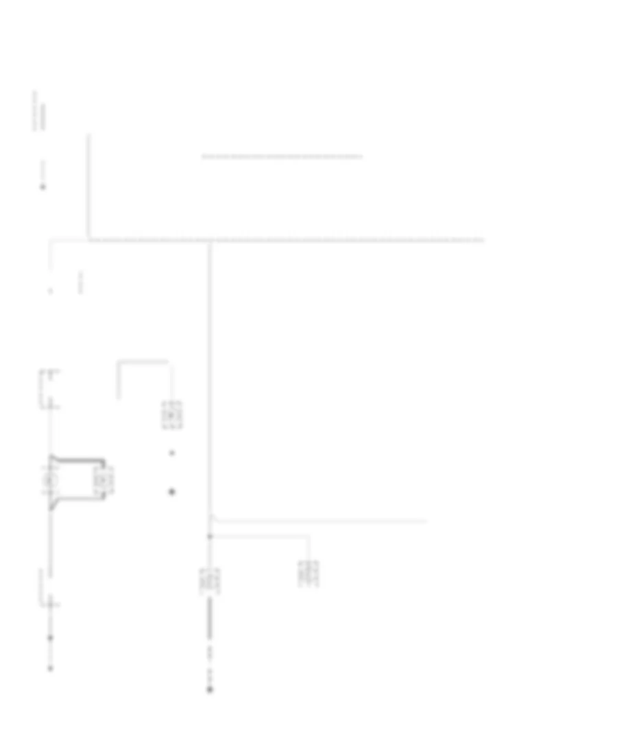 https://portal-diagnostov.com/license.html
Automotive Electricians Portal FZCO
Automotive Electricians Portal FZCO
https://portal-diagnostov.com/license.html
https://portal-diagnostov.com/license.html
Automotive Electricians Portal FZCO
Automotive Electricians Portal FZCOList of elements for Instrument Illumination Wiring Diagram for Pontiac Grand Prix GT 2003:
- (2 door)
- (2 door) (4 door)
- (4 door)
- (w/ u40)
- (w/o u40)
- Ashtray lamp
- Automatic transaxle control position indicator bulb
- Dash dimmer switch
- Driver information center (dic)
- Driver seat heater switch
- Fog lamp switch
- Fuse block
- G200 (right side of dash cross beam, behind fuse block)
- G301 (inside left front door sill, forward of left front seat)
- G302 (right front door sill)
- Head
- Head-up display (hud) switch
- Headlamp switch
- Hot at all times
- Hvac control module
- Inflatable restraint steering wheel module coil
- Instrument cluster
- Left front door lock switch
- Left front window switch
- Left steering wheel controls
- Nca
- Off
- Park
- Park lp fuse 20a
- Prndl dim
- Radio
- Right front door lock switch
- Right front window switch
- Right steering wheel controls
- S203 (dash harn, above cluster)
- S210
- S211
- S212 (dash harn, right side of dash)
- S230
- S303
- S374 (console harn, near transaxle control switch)
- S375
- S406
- S504
- S505
- S506
- S604
- S606
- Str whl ilum fuse 2a
- Underhood fuse block
- W/ ka1
- W/ u40
- W/ uv6
POWER DISTRIBUTION
Power Distribution Wiring Diagram (1 of 4) for Pontiac Grand Prix GT 2003
 https://portal-diagnostov.com/license.html
Automotive Electricians Portal FZCO
Automotive Electricians Portal FZCO
https://portal-diagnostov.com/license.html
https://portal-diagnostov.com/license.html
Automotive Electricians Portal FZCO
Automotive Electricians Portal FZCOList of elements for Power Distribution Wiring Diagram (1 of 4) for Pontiac Grand Prix GT 2003:
- (diagram
- (i/p wiring harn, behind center of dash, 17 cm from data link connector) s202
- (i/p wiring harn, below center of dash, 27 cm from c240) s238
- (onstar jumper harn, 4 cm from vehicle communications unit breakout, toward c423) s423
- 3 of 4)
- Accessory time delay (rap) relay (diagram 2 of 4)
- Air fuse 39 30a
- Alt sense fuse 30 10a
- Ashtray lamp
- Auxiliary power drop connector
- B/u lamp fuse 27 10a
- Batt main 1 fuse 7 60a
- Batt main 2 fuse 4 60a
- Battery
- Blower motor resistor assembly
- Body control module (bcm)
- Cig ltr fuse 15a
- Cigar lighter
- Console accessory power outlet (w/ floor console)
- Cool fan 1 fuse 6 30a
- Cool fan 1 relay 12
- Cool fan 2 fuse 1 30a
- Cool fan 2 relay 10
- Cool fan relay 9
- Data link connector (dlc)
- Daytime running lamps control module
- Driver information center
- E12
- E16
- Ecm sense fuse 33 10a
- Electronic brake control module (ebcm)
- Fog lamp relay 17
- Fog lp fuse 35 10a
- Fuel pump fuse 32 15a
- Fuel pump relay 14
- Fusible link (10 ga- rust)
- G200 (right side of dash crossbeam, behind fuse block)
- Generator
- Hazard fuse 15a
- Headlamp circuit breaker 20a
- Headlamp switch
- Headlamps fuse 3 60a
- Horn fuse 36 15a
- Horn relay 16
- Hvac control module
- Hvac hi fuse 30a
- Hvac/rke batt fuse 29 10a
- I/p fuse block
- Ign main 1 fuse 5 40a
- Ign main 2 fuse 8 60a
- Int lamp fuse 10a
- Nca
- Onstar fuse 10a
- Outside rearview mirror switch
- Park lp fuse 37 20a
- Park/ neutral position switch
- Pass- key fuse 10a
- Powertrain control module (pcm)
- Pwr mir fuse 10a
- R11
- R12
- Rap fuse 10a
- Red
- Remote control door lock receiver (rcdlr)
- S230
- Secondary air injection pump relay
- Starter
- Stop lamp fuse 15a
- Stop lamp switch
- Switch breakout, toward driver inform- ation center) s208
- Theft deterrent led
- Theft deterrent module
- To accessory time delay relay (diagram 2 of 4)
- To ign main relay
- To ignition switch (diagram 2 of 4)
- To power lock fuse (diagram 4 of 4)
- To seat circuit breaker (diagram 4 of 4)
- Turn signal switch
- Underhood fuse block
- V11
- Vehicle interface unit
- Vehicle interface unit (w/ onstar)
Power Distribution Wiring Diagram (2 of 4) for Pontiac Grand Prix GT 2003
 https://portal-diagnostov.com/license.html
Automotive Electricians Portal FZCO
Automotive Electricians Portal FZCO
https://portal-diagnostov.com/license.html
https://portal-diagnostov.com/license.html
Automotive Electricians Portal FZCO
Automotive Electricians Portal FZCOList of elements for Power Distribution Wiring Diagram (2 of 4) for Pontiac Grand Prix GT 2003:
- (dome lamp wiring harn, near center of wind- shield header, 12 cm from inside rearview mirror breakout, toward right vanity mirror lamp) s394
- (front floor console wiring harn, near a/t control, 4 cm from a/t pnk control connector) s376
- (i/p wiring harn, behind right side of dash, 20 cm from driver information center breakout) s209
- (i/p wiring harn, below right side of dash, 8 cm from c200 breakout) s220
- (i/p wiring harn, below steering column, near c201, 21 cm from stoplamp switch)
- (i/p wiring harn, right side of dash 17 cm from fuse block) s240
- (i/p wiring harn, right side of dash, 1 cm from sdm breakout, toward fuse block)
- A13
- Accy
- Automatic transmission shift lock actuator
- Body control module
- Btsi fuse 10a
- Bulb test
- C13
- C201
- Canister vent fuse 10a
- Cruise control module
- Cruise control on/off switch
- Cruise control release switch
- Cruise fuse 10a
- Daytime running lamps (drl) control module
- Driver information center
- Driver window switch
- Drl fuse 10a
- Ecm fuse 10a
- Evaporative emission (evap) canister vent solenoid
- F11
- From ign main 1 fuse (diagram 1 of 4)
- From ign main 2 maxi fuse (diagram 1 of 4)
- From ignition switch (diagram 2 of 4)
- From rap fuse (diagram 1 of 4)
- Head-up display switch
- I/p fuse block
- I/p-ign fuse 10a
- Ignition switch
- Inflatable restraint sensing & diagnostic module (sdm)
- Inflatable restraint steering wheel module coil
- Inside rearview mirror
- Instrument panel cluster
- Lock
- Mall fuse 10a
- Mall pgm fuse 10a
- Nca
- Off
- Park/ neutral position switch
- Pnk
- Pnk b
- Pnk s266
- Power drop connector
- Pwr drop fuse 10a
- Pwr wdo circuit breaker 25a
- Radio
- Radio fuse 10a
- Red
- Retained accessory power (rap) relay (behind glove box)
- Run
- S228
- S264 (i/p wiring harn, below center of dash, 34 cm from c240)
- Sir fuse 15a
- Start
- Steering wheel control
- Stop lamp switch
- Str whl ctrl fuse 2a
- Sunroof fuse 20a
- Sunroof module
- Theft deterrent module
- To canister vent fuse (diagram 2 of 4)
- To dic/hvac fuse (diagram 4 of 4)
- To ign main relay (diagram 3 of 4)
- Turn fuse 10a
- Turn signal switch
- Vehicle interface unit
- Vehicle interface unit (w/ onstar)
- W/ onstar
- W/o onstar
- Windshield wiper motor
- Windshield wiper/washer switch
- Wiper fuse 25a
Power Distribution Wiring Diagram (3 of 4) for Pontiac Grand Prix GT 2003
 https://portal-diagnostov.com/license.html
Automotive Electricians Portal FZCO
Automotive Electricians Portal FZCO
https://portal-diagnostov.com/license.html
https://portal-diagnostov.com/license.html
Automotive Electricians Portal FZCO
Automotive Electricians Portal FZCOList of elements for Power Distribution Wiring Diagram (3 of 4) for Pontiac Grand Prix GT 2003:
- (3.1l) b
- (3.8l) p
- (a/t wiring harn, inside transaxle housing, 19 cm from c113) s115
- (fuel inj wiring harn, on top of engine, 2 cm from fuel inj 2)
- 1-2 shift solenoid valve
- 2-3 shift solenoid valve
- 3.1l
- 3.8l
- A/c clu relay 13
- A/c clu/ abs/ign fuse 28 10a
- A12
- Automatic transaxle
- B12
- C1 b3
- C113
- C12
- C3 c9
- D11
- Electronic brake control module
- Elek ign fuse 25 15a
- Evaporative emissions (evap) canister purge solenoid
- From ecm fuse (diagram 2 of 4)
- From ign main 2 fuse l (diagram 1 of 4)
- Fuel injector
- G113 (on transaxle stud, near starter)
- Heated oxygen sensor (ho2s) 1
- Heated oxygen sensor (ho2s) 2
- Ign main relay
- Ign1-uh fuse 21 15a
- Ignition control module (icm)
- Inj fuse 18 10a
- Mass airflow (maf) sensor
- Nca
- Pnk
- Pnk c10
- Powertrain control module (pcm)
- Red
- S106
- S109
- Secondary air injection air pump relay
- Secondary air injection solenoid (3.8l)
- Stop- lamp switch
- Supercharger boost control solenoid (w/ 3.8l supercharger)
- Tcc fuse 31 10a
- Torque converter clutch (tcc) solenoid valve
- Underhood fuse block
Power Distribution Wiring Diagram (4 of 4) for Pontiac Grand Prix GT 2003
 https://portal-diagnostov.com/license.html
Automotive Electricians Portal FZCO
Automotive Electricians Portal FZCO
https://portal-diagnostov.com/license.html
https://portal-diagnostov.com/license.html
Automotive Electricians Portal FZCO
Automotive Electricians Portal FZCOList of elements for Power Distribution Wiring Diagram (4 of 4) for Pontiac Grand Prix GT 2003:
- (driver seat wiring harn, below driver seat, 10 cm from lumbar adjuster relay breakout)
- (driver seat wiring harn, below driver seat, 36 cm from c311) s331
- (i/p wiring harn, right side of steering column, 20 cm from c200) s236
- (i/p wiring harn, right side of steering column, 4 cm from data link connector breakout) s206
- (w/ 8-speaker sound system)
- Audio amplifier
- Body control module
- Daytime running lamp (drl) control module
- Dic/ hvac fuse 10a
- Driver heated seat control module
- Driver information center (w/ u40)
- Driver seat adjuster switch
- Driver seat heated switch
- Driver seat lumbar switch
- From batt main 2 fuse (diagram 1 of 4)
- From ignition switch (diagram 2 0f 4)
- H seat/ lum fuse 15a
- Hvac control module
- Hvac ctrl fuse 20a
- I/p fuse block
- Left air temperature actuator
- Lumbar horizontal adjuster relay
- Nca
- Pwr lock fuse 15a
- R defog fuse 30a
- Radio
- Radio amp fuse 20a
- Rear window defogger relay
- Red
- Right air temperature actuator
- S332
- Seat circuit breaker 20a
- Seat lumbar verticle adjuster relay
- Vacuum electric solenoid
- W/ heated seats
- W/ power lumbar
- W/o heated seats
- W/o power lumbar
POWER DOOR LOCKS
Power Door Locks Wiring Diagram for Pontiac Grand Prix GT 2003
 https://portal-diagnostov.com/license.html
Automotive Electricians Portal FZCO
Automotive Electricians Portal FZCO
https://portal-diagnostov.com/license.html
https://portal-diagnostov.com/license.html
Automotive Electricians Portal FZCO
Automotive Electricians Portal FZCOList of elements for Power Door Locks Wiring Diagram for Pontiac Grand Prix GT 2003:
- left of steering column)
- (body harness below front passenger seat 11cm (2 in) from breakout for g302)
- (body harness, under right front seat) s314
- (right side of dash cross beam, behind fuse block)
- Accy 1
- All door unlock
- B/u lamp fuse 10a
- Battery
- Battery (b+)
- Body control module (behind left side of dash,
- C13
- Door lk (batt)
- Door lock
- Door unlk cyl
- Door unlock
- Driver door lock cylinder switch
- Driver door lock switch
- Driver unlock
- Drvr dr unlk
- E12
- Front passenger door lock cylinder switch
- Front passenger door lock switch
- G200
- G301 (left front door sill)
- G302 (right front door sill)
- Ground
- Hot at all times
- Hot in accy or run
- Hot in run, bulb test or start
- Hvac/rke batt fuse 10a
- I/p fuse block (behind right side of dash)
- I/p-ign fuse 10a
- Ignition 1
- Int lamp fuse 10a
- Interior lights system
- Left front door lock actuator
- Left rear door lock actuator
- Lock
- Mall fuse 10a
- Nca
- Park input
- Park/neutral/position switch (on transaxle)
- Pass dr unlk
- Pnk
- Pwr lock fuse 15a
- Remote control door lock receiver (behind right side of dash)
- Rfa link
- Right front door lock actuator
- Right rear door lock actuator
- Rr lid release
- S202
- S209
- S285
- S308
- S315 (body harness, under right front seat)
- S504
- S604
- Tan
- Trunk, tailgate, fuel doors system
- Underhood fuse block (mounted to right strut tower)
- Unlock
- Vehicle interface unit (viu) (in trunk, at left rear wheel well)
- W/ on star
- W/o on star
POWER MIRRORS
Electrochromic Mirror Wiring Diagram for Pontiac Grand Prix GT 2003
 https://portal-diagnostov.com/license.html
Automotive Electricians Portal FZCO
Automotive Electricians Portal FZCO
https://portal-diagnostov.com/license.html
https://portal-diagnostov.com/license.html
Automotive Electricians Portal FZCO
Automotive Electricians Portal FZCOList of elements for Electrochromic Mirror Wiring Diagram for Pontiac Grand Prix GT 2003:
- (mirror side) headlight sensor
- (right front door sill) g302
- A8 c1
- Acc voltage
- Ambient air temp sensor signal
- Ambient air temperature sensor
- Ambient light sensor (windshield side)
- B/u lamp fuse 10a
- Exterior lights system
- Gnd
- Hot at all times
- Hot in accy, run, or retained accessory power
- Inside rearview mirror
- Ip fuse block (behind right side of dash)
- Logic
- Low reference
- Park/ neutral position switch (left side of engine compartment, on transaxle)
- Resets to daytime high reflectivity in reverse
- S390
- S394
- S395
- Sunroof fuse 20a
- Underhood fuse block (mounted to right strut tower)
- W/ sunroof
- W/o sunroof
Power Mirrors Wiring Diagram for Pontiac Grand Prix GT 2003
 https://portal-diagnostov.com/license.html
Automotive Electricians Portal FZCO
Automotive Electricians Portal FZCO
https://portal-diagnostov.com/license.html
https://portal-diagnostov.com/license.html
Automotive Electricians Portal FZCO
Automotive Electricians Portal FZCOList of elements for Power Mirrors Wiring Diagram for Pontiac Grand Prix GT 2003:
- (inside left door sill, forward of left front seat) g301
- Driver outside rearview mirror
- Hot at all times
- Ip fuse block (behind right side of dash)
- Left mirror
- Outside rearview mirror switch
- Passenger outside rearview mirror
- Pwr mirr fuse 10a
- Right mirror
- Right/ left motor
- S504
- Up/ down motor
POWER SEATS
6-Way Power Seat Wiring Diagram for Pontiac Grand Prix GT 2003
 https://portal-diagnostov.com/license.html
Automotive Electricians Portal FZCO
Automotive Electricians Portal FZCO
https://portal-diagnostov.com/license.html
https://portal-diagnostov.com/license.html
Automotive Electricians Portal FZCO
Automotive Electricians Portal FZCOList of elements for 6-Way Power Seat Wiring Diagram for Pontiac Grand Prix GT 2003:
- Back
- Driver seat adjuster switch
- Driver seat front vertical motor
- Driver seat horizontal motor
- Driver seat rear vertical motor
- Forward
- Front down
- Front up
- G301 (inside left door sill, forward of left front seat)
- Hot at all times
- I/p fuse block
- Pnk
- Rear down
- Rear up
- S330
- S331
- Seat circuit breaker 20a
- Tan
- W/ power lumbar
Heated Seats Wiring Diagram for Pontiac Grand Prix GT 2003
 https://portal-diagnostov.com/license.html
Automotive Electricians Portal FZCO
Automotive Electricians Portal FZCO
https://portal-diagnostov.com/license.html
https://portal-diagnostov.com/license.html
Automotive Electricians Portal FZCO
Automotive Electricians Portal FZCOList of elements for Heated Seats Wiring Diagram for Pontiac Grand Prix GT 2003:
- Dic/hvac fuse 10a
- Driver heated seat back element
- Driver heated seat control module (below right side of driver's seat, mounted on seat track)
- Driver heated seat switch
- G200 (right side of dash cross beam, behind fuse block)
- G301 (inside left door sill, forward of left front seat)
- Ground
- H seat/lum fuse 15a
- Heated seat cushion cover
- Heated seat element
- Heated seat thermistor
- Hot at all times
- Hot in run
- I/p fuse block
- Illum
- Interior lights system
- Lo/hi in
- Lumbar circuit
- Nca
- On in
- Pnk
- Pnk b
- S206
- S330
- S332
- S375
- Sensor
- W/ power lumbar
Lumbar Wiring Diagram for Pontiac Grand Prix GT 2003
 https://portal-diagnostov.com/license.html
Automotive Electricians Portal FZCO
Automotive Electricians Portal FZCO
https://portal-diagnostov.com/license.html
https://portal-diagnostov.com/license.html
Automotive Electricians Portal FZCO
Automotive Electricians Portal FZCOList of elements for Lumbar Wiring Diagram for Pontiac Grand Prix GT 2003:
- Aft
- Down
- Driver lumbar horizontal motor
- Driver seat lumbar switch
- Fore
- G301 (inside left door sill, forward of left front seat)
- H seat lum fuse 15a
- Heated seat circuit
- Hot at all times
- I/p fuse block
- Lumbar horizontal adjuster relay
- Pnk
- Power seat circuit
- Red
- S330
- S331
- S332
- Seat circuit breaker 20a
- Seat lumbar vertical adjuster relay
- Seat lumbar vertical motor
- Tan
- W/ heated seats
POWER TOP/SUNROOF
Power Top/Sunroof Wiring Diagram for Pontiac Grand Prix GT 2003
 https://portal-diagnostov.com/license.html
Automotive Electricians Portal FZCO
Automotive Electricians Portal FZCO
https://portal-diagnostov.com/license.html
https://portal-diagnostov.com/license.html
Automotive Electricians Portal FZCO
Automotive Electricians Portal FZCOList of elements for Power Top/Sunroof Wiring Diagram for Pontiac Grand Prix GT 2003:
- (not used)
- Battery
- Close
- G302 (right front door sill)
- Gnd
- Hot in run, acc, or rap energized
- I/p fuse block (behind right side of dash, in glove box opening)
- Open
- Pnk
- Pos 1
- Pos 2
- Red
- S390
- S394
- Soft stop
- Sun roof fuse 20a
- Sun roof module (front center of sun roof)
- Sun roof motor (front center of sun roof module)
- Sun roof switch
- Vent
POWER WINDOWS
Power Windows Wiring Diagram, 4 Door for Pontiac Grand Prix GT 2003
 https://portal-diagnostov.com/license.html
Automotive Electricians Portal FZCO
Automotive Electricians Portal FZCO
https://portal-diagnostov.com/license.html
https://portal-diagnostov.com/license.html
Automotive Electricians Portal FZCO
Automotive Electricians Portal FZCOList of elements for Power Windows Wiring Diagram, 4 Door for Pontiac Grand Prix GT 2003:
- (body harness, on floor near center of vehicle, approximately 20 cm (8 in) from 2 cavity black in-line connector under center console) s307
- (inside left door sill, forward of left front seat) g301
- (left front door harness, approximately 8 cm (3 in) from driver door lock switch breakout) s505
- (right front door sill) g302
- 8 cm (3 in) from front passenger door lock switch) s604
- C1 c
- C2 b
- Down
- Driver window motor
- Driver window switch
- Express down
- Express down module
- Front passenger window motor
- Front passenger window switch
- Hot in accy, run & during retained accessory power (rap)
- Illum. lamp
- Illumination
- Instrument panel fuse block (behind right side of dash, in glove box opening)
- Interior lights system
- Left rear window motor
- Left rear window switch
- Lock out switch
- Pwr wdo circuit breaker 25a
- Right rear window motor
- Right rear window switch
- Tan
RADIO
Radio Wiring Diagram, with Amplifier for Pontiac Grand Prix GT 2003
 https://portal-diagnostov.com/license.html
Automotive Electricians Portal FZCO
Automotive Electricians Portal FZCO
https://portal-diagnostov.com/license.html
https://portal-diagnostov.com/license.html
Automotive Electricians Portal FZCO
Automotive Electricians Portal FZCOList of elements for Radio Wiring Diagram, with Amplifier for Pontiac Grand Prix GT 2003:
- A10
- A11
- A12
- Am/fm
- Antenna
- Audio amplifier (under rear shelf panel)
- Audio sig
- B10
- B11
- B12
- Bare
- Battery
- Computer data lines system
- Drain
- E & c data
- G201 (right side of steering column)
- Ground
- Hot at all times
- Hot in acc run or rap
- I/p fuse block (behind right side of dash, in glove box opening)
- Illum
- Inflatable restraint steering wheel control module
- Interior lights system
- Left front door speaker
- Left front door tweeter speaker
- Left rear speaker
- Left rear subwoofer
- Left steering wheel controls
- Lf audio +
- Lf audio -
- Lf feed
- Lf rtn
- Lf spkr +
- Lf spkr -
- Lr audio +
- Lr audio -
- Lr rtn
- Lr spk feed
- Lr spkr +
- Lr spkr -
- Lr sub feed
- Lr sub rtn
- Lt audio sig
- Lt c
- Mute
- Nca
- Pnk
- Preset
- Pwr in
- Radio
- Radio amp fuse 20a
- Radio fuse 10a
- Radio on
- Rear window antenna grid
- Red
- Rf audio +
- Rf audio -
- Rf spkr
- Rf spkr +
- Rf spkr -
- Right front door speaker
- Right front door tweeter speaker
- Right rear right rear speaker speaker
- Right rear right rear subwoofer
- Right steering wheel controls
- Rr audio +
- Rr audio -
- Rr feed
- Rr return
- Rr spkr +
- Rr spkr -
- Rr sub feed
- Rt audio sig
- S239
- S316
- Seek dn
- Seek up
- Source
- St whl cntrl
- Str whl ctrl fuse 2a
- Tan
- Vehicle interface unit (viu) (in trunk, attached to left rear wheelwell)
- Vol dn
- Vol up
Radio Wiring Diagram, without Amplifier for Pontiac Grand Prix GT 2003
 https://portal-diagnostov.com/license.html
Automotive Electricians Portal FZCO
Automotive Electricians Portal FZCO
https://portal-diagnostov.com/license.html
https://portal-diagnostov.com/license.html
Automotive Electricians Portal FZCO
Automotive Electricians Portal FZCOList of elements for Radio Wiring Diagram, without Amplifier for Pontiac Grand Prix GT 2003:
- Am/fm
- Antenna
- Audio sig
- Bare
- Battery
- Computer data lines system
- Drain
- E & c data
- Fuse out
- G201 (right side of steering column)
- Ground
- Hot at all times
- Hot in acc run or rap
- I/p fuse block (behind right side of dash, in glove box opening)
- Illum
- Inflatable restraint steering wheel control module
- Interior lights system
- Left front door speaker
- Left front door tweeter speaker
- Left rear speaker
- Left steering wheel controls
- Lf +
- Lf -
- Lr +
- Lr -
- Lt audio sig
- Mute
- Nca
- Preset
- Radio
- Radio amp fuse 20a
- Radio fuse 10a
- Rear window antenna grid
- Rf +
- Rf -
- Right front door speaker
- Right front door tweeter speaker
- Right rear speaker
- Right steering wheel controls
- Rr +
- Rr -
- Rt audio sig
- S239
- Seek dn
- Seek up
- Source
- St whl in
- Str whl ctrl fuse 2a
- Tan
- Vehicle interface unit (viu) (in trunk, attached to left rear wheelwell)
- Vol dn
- Vol up
SHIFT INTERLOCK
Shift Interlock Wiring Diagram for Pontiac Grand Prix GT 2003
 https://portal-diagnostov.com/license.html
Automotive Electricians Portal FZCO
Automotive Electricians Portal FZCO
https://portal-diagnostov.com/license.html
https://portal-diagnostov.com/license.html
Automotive Electricians Portal FZCO
Automotive Electricians Portal FZCOList of elements for Shift Interlock Wiring Diagram for Pontiac Grand Prix GT 2003:
- A/t shift lock control solenoid (center of console assembly)
- A/t shift lock control solenoid volt
- A/t shift lock solenoid control
- Btsi fuse 10a
- C1 d2
- G117 lower left front of engine, on transaxle stud)
- G200 (right side of dash cross beam, behind fuse block)
- Hot in off, run, bulb test & start
- I/p fuse block (behind right side of dash)
- Ign volt
- Ignition lock cylinder control actuator
- Ignition lock cylinder control switch (closed in park)
- Logic
- Park/neutral position switch (left side of engine compt, on transaxle)
- Pnk
- S105
- S213
- S264
- S376 (floor console harn, near automatic transaxle control)
- Steering column electric park lock (in steering column, near ignition key cylinder)
- Stoplamp switch (on brake pedal support bracket)
- Underhood fuse block (mounted to right strut tower)
STARTING/CHARGING
Charging Wiring Diagram for Pontiac Grand Prix GT 2003
 https://portal-diagnostov.com/license.html
Automotive Electricians Portal FZCO
Automotive Electricians Portal FZCO
https://portal-diagnostov.com/license.html
https://portal-diagnostov.com/license.html
Automotive Electricians Portal FZCO
Automotive Electricians Portal FZCOList of elements for Charging Wiring Diagram for Pontiac Grand Prix GT 2003:
- (not used)
- Alt sense fuse 10a
- Battery
- Charge indicator
- Charge indicator control
- E12
- Fusible link (10 ga- rust)
- G100 (right side of eng compt, at base of battery)
- G113 (lower right front of eng, on transaxle stud, near starter)
- Gen. terminal l output
- Generator input
- Generator l
- Head-up display
- Hot at all times
- Hot in run, bulb test or start
- I/p fuse block (behind right side of dash, in glove box opening)
- Instrument panel cluster
- Ip-ign fuse 10a
- P b+
- Pnk
- Pnk i
- Powertrain control module (pcm) (left front side of engine compartment, in air cleaner assembly)
- Red
- S209
- Starter
- Underhood fuse block (mounted to right strut tower)
Starting Wiring Diagram for Pontiac Grand Prix GT 2003
 https://portal-diagnostov.com/license.html
Automotive Electricians Portal FZCO
Automotive Electricians Portal FZCO
https://portal-diagnostov.com/license.html
https://portal-diagnostov.com/license.html
Automotive Electricians Portal FZCO
Automotive Electricians Portal FZCOList of elements for Starting Wiring Diagram for Pontiac Grand Prix GT 2003:
- Acc
- Battery
- Bulb test
- G100 (right side of eng compt, at base of battery)
- G113 (lower right front of eng, on transaxle stud, near starter)
- Hold-in coil
- Ign main 1 fuse 40a
- Ignition switch
- Lock
- Off
- Park/neutral position switch (left side of engine compartment, on transaxle)
- Pull-in coil
- Red
- Run
- Start
- Starter
- Starter motor
- Underhood fuse block (mounted to right strut tower)
SUPPLEMENTAL RESTRAINTS
Supplemental Restraints Wiring Diagram for Pontiac Grand Prix GT 2003
 https://portal-diagnostov.com/license.html
Automotive Electricians Portal FZCO
Automotive Electricians Portal FZCO
https://portal-diagnostov.com/license.html
https://portal-diagnostov.com/license.html
Automotive Electricians Portal FZCO
Automotive Electricians Portal FZCOList of elements for Supplemental Restraints Wiring Diagram for Pontiac Grand Prix GT 2003:
- (dash harness, below right side of dash, 4cm from blower motor resistor breakout)
- (i/p harness, behind right side of dash, 20cm from driver information center breakout)
- (left side of dash, at base of steering column) g205
- (part of driver's seat belt assembly) (open when buckled) seat belt switch
- A10
- A11
- A12
- A13
- A14
- A15
- A16
- A17
- A18
- Air bag ind
- B1-b8
- Bar
- Body control module (bcm) (behind left side of dash, left of steering column)
- C1-c8
- Case ground
- Data link connector (dlc) (partial) (under left side of dash, right of steering column)
- G301 (inside left door sill, forward of left front seat)
- Ground
- High control
- Hot in run, bulb test & start
- Ignition
- Inflatable restraint i/p module
- Inflatable restraint sensing & diagnostic module (sdm) (under right front seat)
- Inflatable restraint steering wheel module
- Inflatable restraint steering wheel module coil
- Inflatable restraint warning indicator
- Instrument panel cluster (ipc)
- Instrument panel fuse block (behind right side of dash, in glove box opening)
- Ip-ign fuse 10a
- Low control
- Nca
- Not used
- Pnk
- S209
- S218
- Seat belt sw
- Seat belt switch c2
- Serial data
- Shorting
- Shorting bar
- Sir fuse 15a
TRANSMISSION
A/T Wiring Diagram for Pontiac Grand Prix GT 2003
 https://portal-diagnostov.com/license.html
Automotive Electricians Portal FZCO
Automotive Electricians Portal FZCO
https://portal-diagnostov.com/license.html
https://portal-diagnostov.com/license.html
Automotive Electricians Portal FZCO
Automotive Electricians Portal FZCOList of elements for A/T Wiring Diagram for Pontiac Grand Prix GT 2003:
- (3.1l)
- (3.8l)
- (in fuel injector harness) s121
- (on throttle body assembly) throttle position sensor
- (under left side of dash, right of steering column) (partial) data link connector (dlc)
- (w/ 3.1l engine)
- (w/ 3.8l engine)
- 1-2 shift sol
- 2-3 shift sol
- 3.8l 3.1l
- 5v reference a
- A/t iss sensor hi
- A/t iss sensor lo
- A12
- Automatic transaxle
- Automatic transaxle fluid pressure manual valve position switch
- Automatic transaxle fluid temperature sensor
- Automatic transaxle input shaft speed sensor
- B10
- Battery in
- Body control module, driver information center (dic), head up display (hud) switch
- C10
- Class ii data
- Computer data lines system
- D10
- D11
- Ecm fuse 10a
- Ecm sense fuse 33 10a
- Ect sens ret
- Ect sensor in
- Engine controls system (map sensor)
- Engine coolant temperature (ect) sensor (top left rear of engine, below throttle body)
- F12
- G113 (lower left front of engine, on transaxle stud)
- Hot at all times
- Hot in run, bulb test or start
- I/p fuse block (behind right side of dash)
- I/p ign fuse 10a
- Ign main relay
- Ignition in
- Instrument panel cluster (ipc)
- Instrument panel cluster (ipc)
- Malfunction indicator lamp
- Map/ect sens ret
- Mil ctrl
- Pc sol hi
- Pc sol lo
- Pcm ground
- Pnk
- Powertrain control module (pcm) (left front side of engine compt, in air cleaner assembly)
- Pressure control sol
- Red
- S106
- S131 (engine harn, near breakout to ebtcm module)
- S209
- S218 (dash harn, near breakout to blower motor)
- Stop lamp switch (on brake pedal support bracket)
- Tan
- Tcc fuse 31 10a
- Tcc pwm sol
- Tcc release
- Tcc release in
- Tcc/ brake switch
- Tcc/brake sw in
- Tft sensor in
- Tft sensor return
- Tp sensor in
- Tp sensor return
- Tr sw a
- Tr sw b
- Tr sw c
- Tr sw in-a
- Tr sw in-b
- Tr sw in-c
- Tr sw in-p
- Tr sw p
- Transmission internal mode switch
- Uart data
- Underhood fuse block (mounted to right strut tower)
- Vehicle speed sensor (vss) (lower right side of engine compt, on transaxle)
- Vss hi in
- Vss lo in
TRUNK, TAILGATE, FUEL DOOR
Trunk Release Wiring Diagram for Pontiac Grand Prix GT 2003
 https://portal-diagnostov.com/license.html
Automotive Electricians Portal FZCO
Automotive Electricians Portal FZCO
https://portal-diagnostov.com/license.html
https://portal-diagnostov.com/license.html
Automotive Electricians Portal FZCO
Automotive Electricians Portal FZCOList of elements for Trunk Release Wiring Diagram for Pontiac Grand Prix GT 2003:
- B/u lamp fuse 10a
- Body control module (bcm) (left of steering column)
- C1 c
- C1 e4
- G302 (right front door sill)
- Hot at all times
- Park input
- Park/ neutral position switch (left side of engine compt, on transaxle)
- Rear compartment lid release actuator (mounted to rear compt lid, near latch)
- Rear compartment lid release relay (below left side of dash, mounted to bcm mounting bracket)
- Rear compartment lid release switch
- Remote control door lock receiver (rcdlr) (right side of dash, behind inflatable restraint module)
- S416
- Underhood fuse block (mounted to right front strut tower)
WARNING SYSTEMS
Warning Systems Wiring Diagram for Pontiac Grand Prix GT 2003
 https://portal-diagnostov.com/license.html
Automotive Electricians Portal FZCO
Automotive Electricians Portal FZCO
https://portal-diagnostov.com/license.html
https://portal-diagnostov.com/license.html
Automotive Electricians Portal FZCO
Automotive Electricians Portal FZCOList of elements for Warning Systems Wiring Diagram for Pontiac Grand Prix GT 2003:
- (closed w/key in ignition)
- (i/p wiring harness behind right side of instrument cluster, approx. 7 cm (3 in) from driver information center breakout)
- (i/p wiring harness, behind right side of instrument cluster, approx. at driver information center breakout)
- Accessory voltage
- Battery
- Bcm program enable
- Body control module (bcm) (below left side of dash, left of steering column)
- C12
- C13
- C14
- C15
- Chime module signal
- Cruise control system
- D12
- Driver door lock
- Driver information center (dic)
- Driver's door sw sig
- Fasten belts indicator
- G200 (right side of dash cross beam, behind fuse block)
- G301 (inside left door sill, forward of left front seat)
- Ground
- Hdlp sw off signal
- Head
- Headlamp switch
- Hot at all times
- Hot in accy & run
- Hot in run, bulb test & start
- I/p fuse block (right side of dash, in i/p compartment opening)
- I/p-ign fuse 10a
- Ignition 1 voltage
- Ignition key alarm switch
- Instrument cluster system
- Instrument panel cluster (ipc)
- Int lamp fuse 10a
- Key in ign sw sig
- Left seat belt sw
- Left turn signal
- Mall fuse 10a
- Mall pgm fuse 10a
- Nca
- Off
- Open switch signal
- Park
- Park lp fuse 37 20a
- Pnk
- Powertrain control module (pcm) (left side of engine compartment, inside air cleaner assembly)
- Right turn signal
- S208
- S209
- S230
- S285
- S289
- S290
- S504
- Seat belt ind
- Seat belt switch (inside right half of driver's seat belt)
- Tan
- Turn signal multifunction lever
- Underhood fuse block (right side of engine compartment, mounted to strut tower)
- Vehicle speed sig
WIPER/WASHER
Wiper/Washer Wiring Diagram for Pontiac Grand Prix GT 2003
 https://portal-diagnostov.com/license.html
Automotive Electricians Portal FZCO
Automotive Electricians Portal FZCO
https://portal-diagnostov.com/license.html
https://portal-diagnostov.com/license.html
Automotive Electricians Portal FZCO
Automotive Electricians Portal FZCOList of elements for Wiper/Washer Wiring Diagram for Pontiac Grand Prix GT 2003:
- (left side of engine compartment, at base of left strut tower) g119
- (left side of front end upper tie bar) g101
- (w/ digital display)
- (w/o digital display)
- A12
- Delay
- Driver information center (right side of i/p cluster)
- E11
- F12
- Hot in accy & run
- I/p fuse block (behind right side of dash, in glove box opening)
- Mist
- Multifunction turn signal lever
- Off
- Red
- S124
- S125
- S249
- Underhood fuse block (mounted to right strut tower)
- Washer switch
- Wind- shield washer fluid level switch (in washer fluid reservoir)
- Windshield washer fluid pump (in washer fluid reservoir)
- Windshield wiper motor (on left side of firewall)
- Wiper fuse 25a
- Wiper motor
- Wiper motor controller
- Wiper switch

 Čeština
 Dansk
Dansk Deutsch
 Ελληνικά
 English
 English
 Español
 Suomi
Suomi Français
 Français
 עברית
עברית Hrvatski
 Magyar
 Italiano
 한국어
한국어 Nederlands
 Polski
 Português
 Português
 Română
 Русский
 Slovenčina
 Slovenščina
 Svenska
 Türkçe
 中文 (中国)
