AIR CONDITIONING
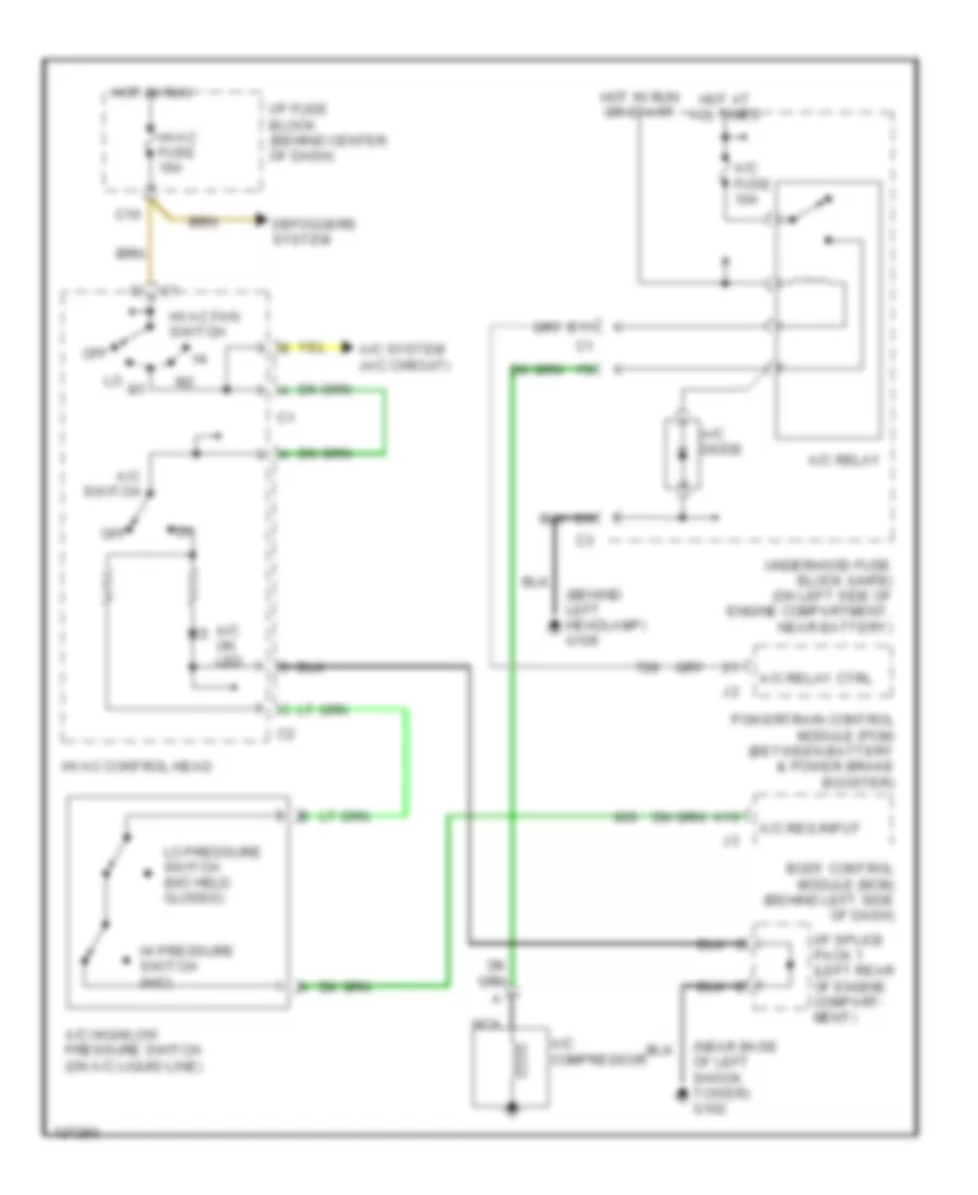
A/C Wiring Diagram for Saturn SC1 2000
 https://portal-diagnostov.com/license.html
Automotive Electricians Portal FZCO
Automotive Electricians Portal FZCO
https://portal-diagnostov.com/license.html
https://portal-diagnostov.com/license.html
Automotive Electricians Portal FZCO
Automotive Electricians Portal FZCO
List of elements for A/C Wiring Diagram for Saturn SC1 2000:
- (behind left headlamp) g106
- (below center of dash) g206
- (near base of left shock tower) g102
- (rear of engine) g115
- 0.31 ohms
- 0.61 ohms
- 1.85 ohms
- A/c compressor
- A/c diode
- A/c fuse 10a
- A/c high/low pressure switch (on a/c liquid line)
- A/c on led
- A/c relay
- A/c relay ctrl
- A/c request input
- A/c switch
- A10
- A11
- B10
- Blower motor (on lower right side of dash)
- Blower motor resistors (on top of hvac module)
- Body control module (bcm) (behind left side of dash)
- Cool fan fuse 30a
- Cool fan mtr ctrl
- Cool fan relay
- Cool temp return
- Cool temp signal
- Cooling fan motor (on front center of engine compartment)
- Defoggers system
- Dim illumination
- Dim illumination (a/c & recirculation switch)
- E11
- Engine coolant temperature sensor (on rear of cylinder head)
- Fan sw high input
- Hi pressure switch (n/c)
- Hot at all times
- Hot in run
- Hot in run or start
- Hvac blower relay
- Hvac control head
- Hvac fan switch
- Hvac fuse 15a
- I/p fuse block (behind center of dash)
- I/p splice pack 1 (left rear of engine compartment)
- Ign3 fuse 30a
- Interior lights system
- Lo pressure switch (n/o held closed)
- Nca
- Off
- Powertrain control module (pcm) (between battery & power brake booster)
- Recirc door motor (on right end of hvac module)
- Recirc led
- Recirculation switch
- Red
- Relay control
- Tan
- Underhood fuse block (uhfb) (on left side of engine compartment, near battery)
- Vehicle speed sensor (vss) (on right side of transaxle differential)
- Vss hi input
- Vss lo input
Compressor Wiring Diagram for Saturn SC1 2000
 https://portal-diagnostov.com/license.html
Automotive Electricians Portal FZCO
Automotive Electricians Portal FZCO
https://portal-diagnostov.com/license.html
https://portal-diagnostov.com/license.html
Automotive Electricians Portal FZCO
Automotive Electricians Portal FZCOList of elements for Compressor Wiring Diagram for Saturn SC1 2000:
- (behind left headlamp) g106
- (near base of left shock tower) g102
- A/c compressor
- A/c diode
- A/c fuse 10a
- A/c high/low pressure switch (on a/c liquid line)
- A/c on led
- A/c relay
- A/c relay ctrl
- A/c req input
- A/c switch
- A/c system (a/c circuit)
- A10
- Body control module (bcm) (behind left side of dash)
- C10
- Defoggers system
- E11
- Hi pressure switch (n/c)
- Hot at all times
- Hot in run
- Hot in run or start
- Hvac control head
- Hvac fan switch
- Hvac fuse 15a
- I/p fuse block (behind center of dash)
- I/p splice pack 1 (left rear of engine compart- ment)
- Lo pressure switch (n/o held closed)
- Nca
- Off
- Powertrain control module (pcm) (between battery & power brake booster)
- Underhood fuse block (uhfb) (on left side of engine compartment, near battery)
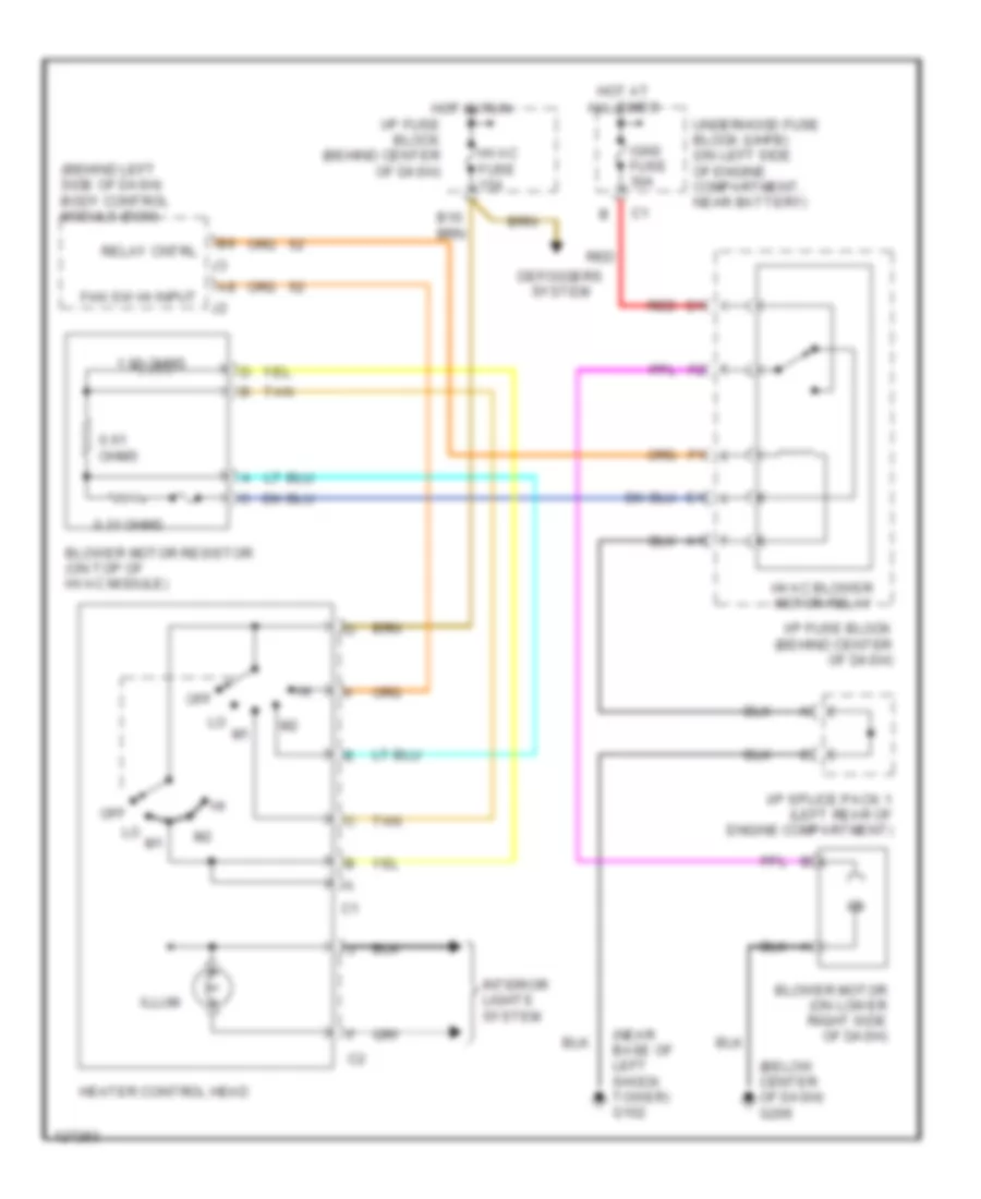
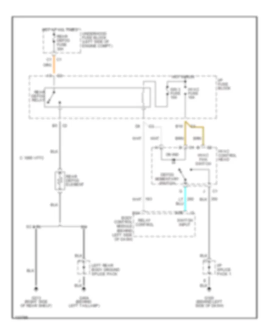
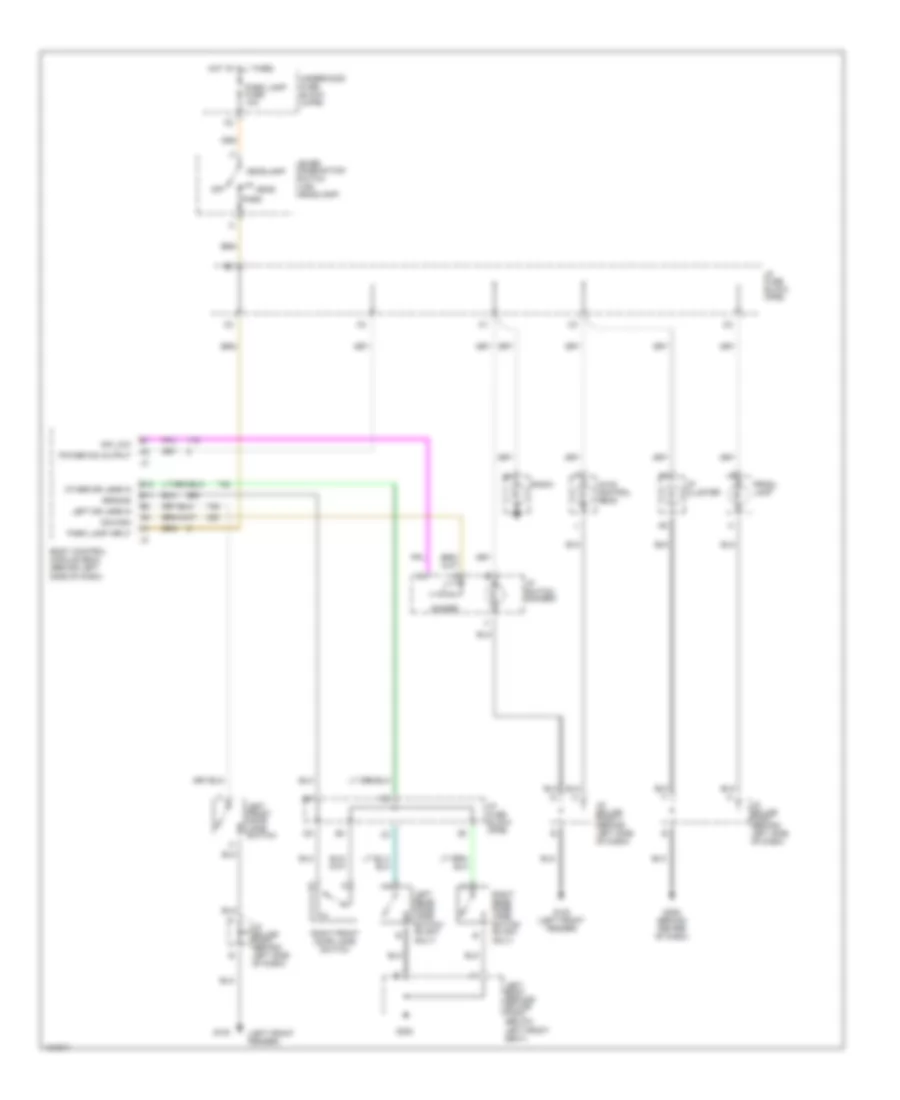
Heater Wiring Diagram for Saturn SC1 2000
 https://portal-diagnostov.com/license.html
Automotive Electricians Portal FZCO
Automotive Electricians Portal FZCO
https://portal-diagnostov.com/license.html
https://portal-diagnostov.com/license.html
Automotive Electricians Portal FZCO
Automotive Electricians Portal FZCOList of elements for Heater Wiring Diagram for Saturn SC1 2000:
- (behind left side of dash) body control module (bcm)
- (below center of dash) g206
- (near base of left shock tower) g102
- 0.31 ohms
- 0.61 ohms
- 1.85 ohms
- B10
- Blower motor (on lower right side of dash)
- Blower motor resistor (on top of hvac module)
- Defoggers system
- Fan sw hi input
- Heater control head
- Hot at all times
- Hot in run
- Hvac blower motor relay
- Hvac fuse 15a
- I/p fuse block (behind center of dash)
- I/p splice pack 1 (left rear of engine compartment)
- Ign3 fuse 30a
- Illum
- Interior lights system
- Off
- Red
- Relay cntrl
- Tan
- Underhood fuse block (uhfb) (on left side of engine compartment, near battery)
ANTI-LOCK BRAKES
Anti-lock Brake Wiring Diagrams for Saturn SC1 2000
 https://portal-diagnostov.com/license.html
Automotive Electricians Portal FZCO
Automotive Electricians Portal FZCO
https://portal-diagnostov.com/license.html
https://portal-diagnostov.com/license.html
Automotive Electricians Portal FZCO
Automotive Electricians Portal FZCOList of elements for Anti-lock Brake Wiring Diagrams for Saturn SC1 2000:
- (left front fender)
- A c6
- A11 c1
- Abs fuse 50a
- Abs indicator
- Batt
- Bo7
- Bo8
- Bo9
- Body control module (bcm) (behind left side of dash)
- Brake fuse 15a
- Brake pressure modulator valve (bpmv)
- Brake sw in
- C 1995 vftc
- Computer data lines system
- Data link connector (dlc) (under left side of dash)
- E10
- E2 c1
- Electronic brake/traction control module (ebtcm) (at left rear of engine compartment)
- F10
- G100
- G102 (near base of left shock tower)
- Hot at all times
- Hot in run
- Hot in run or start
- I/p fuse block
- I/p splice pack 1 (behind left side of dash)
- I/p switch
- Ign
- Ign 1 fuse 10a
- Ign 3 fuse 15a
- Instrument cluster
- Left front wheel speed sensor
- Left rear wheel speed sensor
- Lf whl spd sens
- Lr whl spd sens
- Module sol grd
- Nca
- Pmp mtr grd
- Pnk
- Powertrain control module (pcm) (between battery & power brake booster)
- Pwr out
- Red
- Rf whl spd sens
- Right front wheel speed sensor
- Right rear wheel speed sensor
- Rr whl spd sens
- Serial data
- Stoplight switch (on brake pedal bracket)
- Tan
- Trac sw in
- Traction active indicator
- Traction off ind
- Underhood junction block
ANTI-THEFT
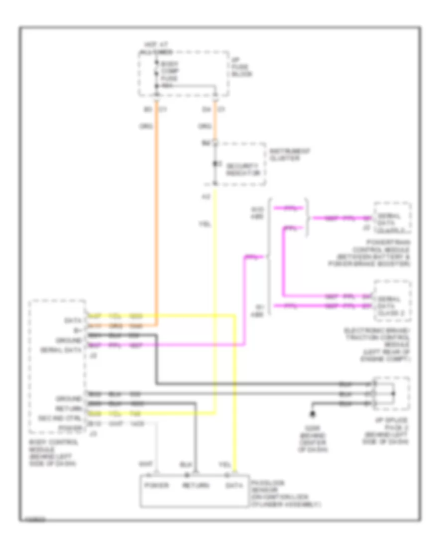
Anti-theft Wiring Diagram for Saturn SC1 2000
 https://portal-diagnostov.com/license.html
Automotive Electricians Portal FZCO
Automotive Electricians Portal FZCO
https://portal-diagnostov.com/license.html
https://portal-diagnostov.com/license.html
Automotive Electricians Portal FZCO
Automotive Electricians Portal FZCOList of elements for Anti-theft Wiring Diagram for Saturn SC1 2000:
- A07
- A11
- B01
- B02
- B03
- B07
- B09
- B10
- Body comp fuse 10a
- Body control module (behind left side of dash)
- Data
- Electronic brake/ traction control module (left rear of engine compt)
- G206 (behind center of dash)
- Ground
- Hot at all times
- I/p fuse block
- I/p splice pack 2 (behind left side of dash)
- Instrument cluster
- Passlock sensor (on ignition lock cylinder assembly)
- Power
- Powertrain control module (between battery & power brake booster)
- Return
- Sec ind ctrl
- Security indicator
- Serial data
- Serial data class 2
- W/ abs
- W/o abs
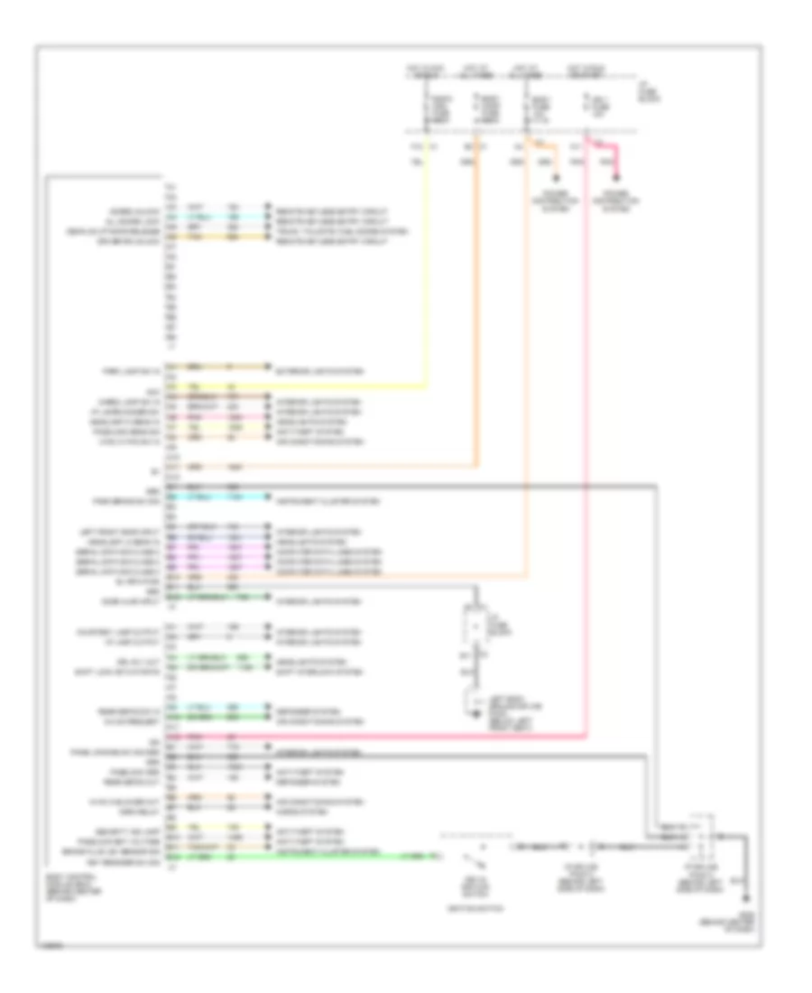
BODY COMPUTER
Body Computer Wiring Diagrams for Saturn SC1 2000
 https://portal-diagnostov.com/license.html
Automotive Electricians Portal FZCO
Automotive Electricians Portal FZCO
https://portal-diagnostov.com/license.html
https://portal-diagnostov.com/license.html
Automotive Electricians Portal FZCO
Automotive Electricians Portal FZCOList of elements for Body Computer Wiring Diagrams for Saturn SC1 2000:
- A/c sw request
- A10
- A11
- A12
- Acc
- Air conditioning system
- All doors lock
- Anti-theft system
- B+ (rfa pwr)
- B10
- B11
- B12
- Body comp fuse 10a
- Body control module (bcm) (behind center of dash)
- Body fuse 10a
- Brake fluid lev sensor sig
- Cargo lamp sw in
- Computer data lines system
- Courtesy lamp output
- Decklid/liftgate release
- Defogger system
- Door ajar input
- Doors unlock
- Driver dr unlock
- Drl rly out
- Exterior lights system
- F12
- G206 (behind center of dash)
- Grd
- Headlamp hi beam in
- Headlamp lo beam in
- Headlights system
- Horn relay
- Horns system
- Hot at all times
- Hot in acc or run
- Hot in run or start
- Hvac hi blower out
- Hvac hi fan sw in
- I/p fuse block
- I/p lamp output
- I/p lamps dimmer sw
- I/p splice pack 2 (behind left side of dash)
- Ign
- Ign 1 fuse 10a
- Ignition switch
- Instrument cluster system
- Interior lights system
- Key reminder sw sig
- Key-in ignition switch
- Left body ground splice pack (below left front seat)
- Left front door input
- Panel dimming sw sig grd
- Park brake sw sig
- Park lamp sw in
- Passlock bat voltage
- Passlock grd
- Passlock sens sig
- Pnk
- Power distribution system
- Radio (ign) fuse 10a
- Rear defog out
- Rear defog sw in
- Remote keyless entry circuit
- Security ind lamp
- Serial data sig class 2
- Shift interlock system
- Shift lock actuator fd
- Tan
- Trunk, tailgate, fuel doors system
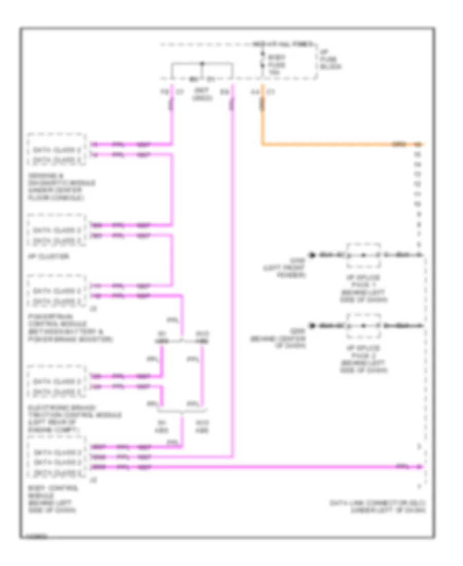
COMPUTER DATA LINES
Computer Data Lines for Saturn SC1 2000
 https://portal-diagnostov.com/license.html
Automotive Electricians Portal FZCO
Automotive Electricians Portal FZCO
https://portal-diagnostov.com/license.html
https://portal-diagnostov.com/license.html
Automotive Electricians Portal FZCO
Automotive Electricians Portal FZCOList of elements for Computer Data Lines for Saturn SC1 2000:
- data class 2
- (not used)
- B07
- B08
- B09
- Body control module (behind left side of dash)
- Body fuse 10a
- C1 a4
- C1 f8
- Data class 2
- Data link connector (dlc) (under left of dash)
- Electronic brake/ traction control module (left rear of engine compt)
- G100 (left front fender)
- G206 (behind center of dash)
- Hot at all times
- I/p cluster
- I/p fuse block
- I/p splice pack 1 (behind left side of dash)
- I/p splice pack 2 (behind left side of dash)
- Powertrain control module (between battery & power brake booster)
- Sensing & diagnostic module (under center floor console)
- W/ abs
- W/o abs
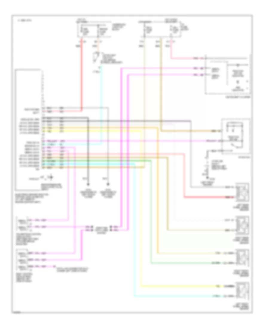
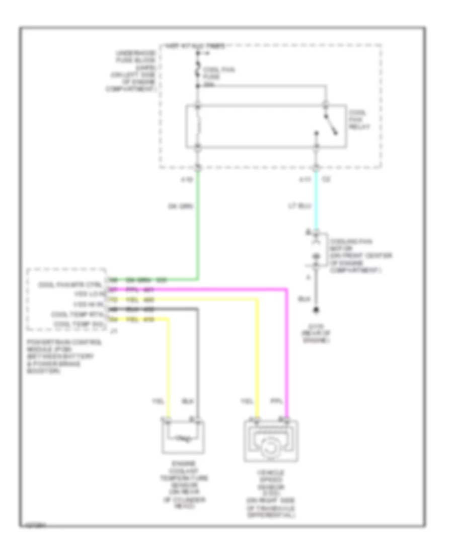
COOLING FAN
Cooling Fan Wiring Diagram for Saturn SC1 2000
 https://portal-diagnostov.com/license.html
Automotive Electricians Portal FZCO
Automotive Electricians Portal FZCO
https://portal-diagnostov.com/license.html
https://portal-diagnostov.com/license.html
Automotive Electricians Portal FZCO
Automotive Electricians Portal FZCOList of elements for Cooling Fan Wiring Diagram for Saturn SC1 2000:
- A10
- A11
- Cool fan fuse 30a
- Cool fan mtr ctrl
- Cool fan relay
- Cool temp rtn
- Cool temp sig
- Cooling fan motor (on front center of engine compartment)
- Engine coolant temperature sensor (on rear
- G115 (rear of engine)
- Hot at all times
- Of cylinder head)
- Of transaxle differential)
- Powertrain control module (pcm) (between battery & power brake booster)
- Underhood fuse block (uhfb) (on left side of engine compartment)
- Vehicle speed sensor (vss) (on right side
- Vss hi in
- Vss lo in
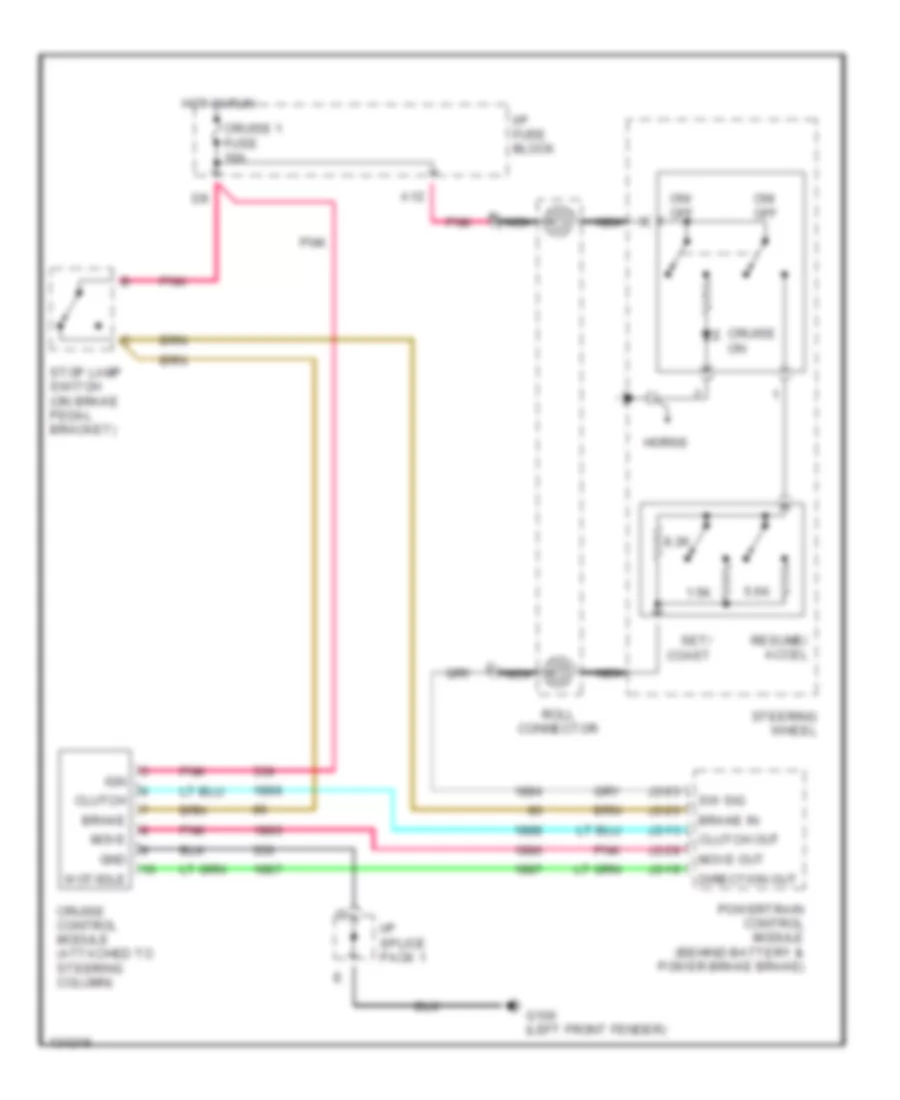
CRUISE CONTROL
Cruise Control Wiring Diagram for Saturn SC1 2000
 https://portal-diagnostov.com/license.html
Automotive Electricians Portal FZCO
Automotive Electricians Portal FZCO
https://portal-diagnostov.com/license.html
https://portal-diagnostov.com/license.html
Automotive Electricians Portal FZCO
Automotive Electricians Portal FZCOList of elements for Cruise Control Wiring Diagram for Saturn SC1 2000:
- 1.5k
- 5.6k
- 8.2k
- A12
- Brake
- Brake in
- Clutch
- Clutch out
- Cruise 1 fuse 10a
- Cruise control module (attached to steering column)
- Cruise on
- Direction out
- G100 (left front fender)
- Gnd
- Horns
- Hot in run
- I/p fuse block
- I/p splice pack 1
- Ign
- J2-03
- J2-13
- J2-19
- J2-26
- J2-28
- Move
- Move out
- Nca
- On/ off
- Pnk
- Powertrain control module (behind battery & power brake brake)
- Resume/ accel
- Roll connector
- Set/ coast
- Steering wheel
- Stop lamp switch (on brake pedal bracket)
- Sw sig
- Wot/idle
DEFOGGERS
Defogger Wiring Diagram for Saturn SC1 2000
 https://portal-diagnostov.com/license.html
Automotive Electricians Portal FZCO
Automotive Electricians Portal FZCO
https://portal-diagnostov.com/license.html
https://portal-diagnostov.com/license.html
Automotive Electricians Portal FZCO
Automotive Electricians Portal FZCOList of elements for Defogger Wiring Diagram for Saturn SC1 2000:
- 1995 vftc c
- A09
- B10
- Bo4
- Body control module (behind left side of dash)
- Defog momentary switch
- Defog relay
- G100 (behind left side of dash)
- G313 (right side of rear shelf)
- G404 (behind left taillamp)
- Hot at all times
- Hot in run
- Hvac control head
- Hvac fan switch
- Hvac fuse 10a
- I/p fuse block
- I/p splice pack 1
- Ign 3 fuse 10a
- Left rear body ground splice pack
- On ind
- Rear
- Rear defog element
- Rear defog fuse 30a
- Relay control
- Sc & sl
- Switch input
- Underhood fuse block (left side of engine compt)
ENGINE PERFORMANCE
1.9L
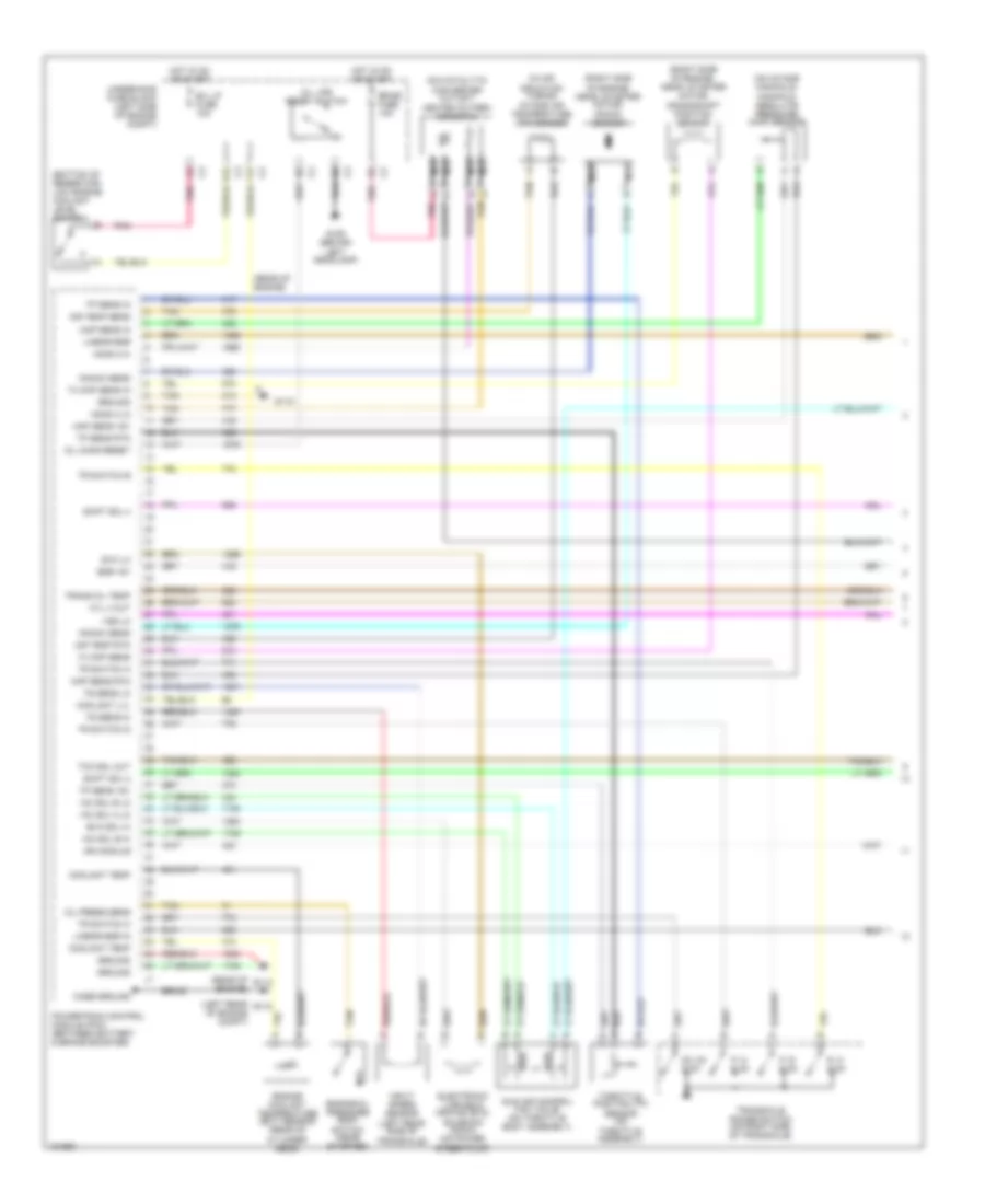
1.9L VIN 8, Engine Performance Wiring Diagrams (1 of 3) for Saturn SC1 2000
 https://portal-diagnostov.com/license.html
Automotive Electricians Portal FZCO
Automotive Electricians Portal FZCO
https://portal-diagnostov.com/license.html
https://portal-diagnostov.com/license.html
Automotive Electricians Portal FZCO
Automotive Electricians Portal FZCOList of elements for 1.9L VIN 8, Engine Performance Wiring Diagrams (1 of 3) for Saturn SC1 2000:
- (bottom of reservoir) low engine coolant level switch
- (in air induction tubing) intake air temperature (iat) sensor
- (left rear of engine compt)
- (on catalytic
- (on intake manifold) manifold absolute pressure (map) sensor
- (rear of engine)
- (right side of engine, near, starter motor) crankshaft position sensor
- (right side of engine, near, starter motor) knock sensor
- 7x ckp sens
- 7x ckp sens in
- A tan
- A12
- Air temp rtn
- Air temp sens
- B/u lp fuse 10a
- Braid
- Case ground
- Converter outlet)
- Coolant lvl
- Coolant temp
- Cyl 4 out
- Cylinder head)
- D pnk
- D2, d3 & d4
- Egr +5v
- Electronic variable orifice (evo) solenoid (dohc) (on power steer pump)
- Emiss fuse 10a
- Engine coolant temperature (ect) sensor (rear of
- Engine oil pressure (eop) switch (near starter)
- Evo lo
- Evo sol hi
- F12
- G106 (behind left headlamp)
- G115
- G116
- Ground
- H2os 2 hi
- H2os 2 lo
- Heated oxygen sensor 2
- Hot in on or start
- Iac sol a lo
- Iac sol b hi
- Iac sol b lo
- Idle air control (iac) valve (on throttle body assembly)
- Ign module
- Input speed sensor (left rear side of transaxle)
- Knock sens
- Linear egr
- Linear egr in
- Map sens +5v
- Map sens in
- Map sens rtn
- Nca
- Nca a
- Nca b
- Oil chng reset
- Oil life reset switch
- Oil press sens
- P, n & d3
- P, r & d2
- Pnk
- Powertrain control module (pcm) (between battery & brake booster)
- R, n & d4
- Shift sol 2
- Shift sol 4
- Tan
- Tcc sol out
- Throttle position (tp) sensor (on throttle assembly)
- Tp sens +5v
- Tp sens in
- Tp sens rtn
- Tr switch a
- Tr switch b
- Tr switch c
- Tr switch d
- Trans oil temp
- Transaxle range switch (on right side of transaxle)
- Ts sens hi
- Ts sens lo
- Underhood fuse block (left side of engine compt)
- Vss lo
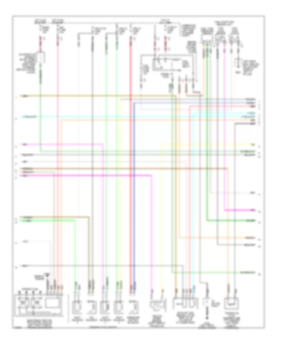
1.9L VIN 8, Engine Performance Wiring Diagrams (2 of 3) for Saturn SC1 2000
 https://portal-diagnostov.com/license.html
Automotive Electricians Portal FZCO
Automotive Electricians Portal FZCO
https://portal-diagnostov.com/license.html
https://portal-diagnostov.com/license.html
Automotive Electricians Portal FZCO
Automotive Electricians Portal FZCOList of elements for 1.9L VIN 8, Engine Performance Wiring Diagrams (2 of 3) for Saturn SC1 2000:
- (behind center of dash) i/p fuse block
- (rear of engine)
- Eis fuse 10a
- Electronic ignition (ei) control module (left front side of transaxle housing)
- Emiss fuse 10a
- Evaporative emission (evap) purge solenoid (right side of engine, above starter motor)
- Exhaust gas recirculation (egr) valve (on side of cylinder head)
- Fuel level sensor
- Fuel pump fuse 10a
- Fuel pump motor
- Fuel pump relay
- Fuel pump/tank sensor unit
- Fuel tank pressure sensor
- G102 (left front shock tower)
- G115
- G904
- Hot at all times
- Hot in on or start
- I/p batt fuse 30a
- I/p splice pack 1
- Left rear body ground splice pack (base of left "c" pillar)
- Pnk
- Pnk a
- Pressure control solenoid
- Probe hole
- Red
- Red e
- Red g
- Shift solenoid
- Side of transaxle)
- Spark plugs
- Tcc solenoid
- Transaxle fluid temperature (tft) sensor (left rear
- Transaxle solenoids
- Trs 2/tcc fuse 10a
- Trs 3/4 fuse 10a
- Trs lp fuse 10a
- Underhood fuse block (left side of engine compt)
- Vehicle speed sensor (right side of transaxle)
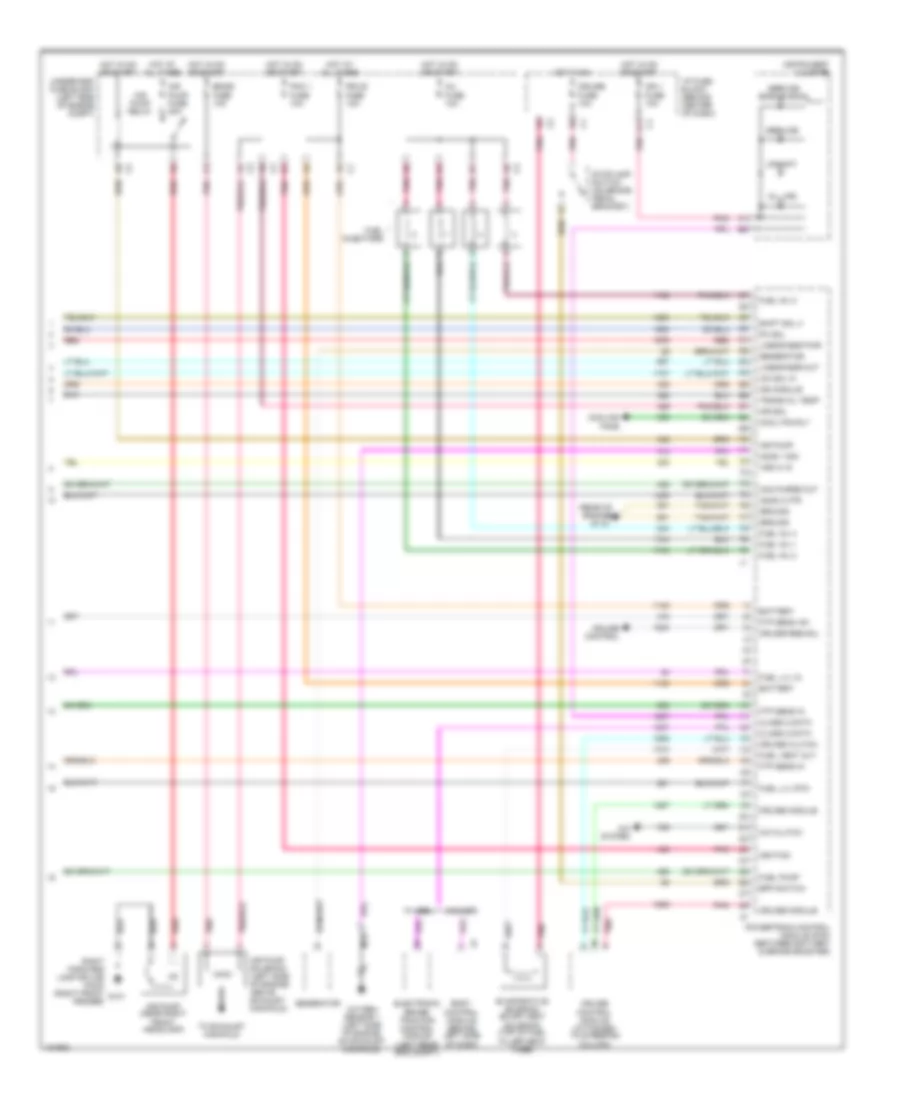
1.9L VIN 8, Engine Performance Wiring Diagrams (3 of 3) for Saturn SC1 2000
 https://portal-diagnostov.com/license.html
Automotive Electricians Portal FZCO
Automotive Electricians Portal FZCO
https://portal-diagnostov.com/license.html
https://portal-diagnostov.com/license.html
Automotive Electricians Portal FZCO
Automotive Electricians Portal FZCOList of elements for 1.9L VIN 8, Engine Performance Wiring Diagrams (3 of 3) for Saturn SC1 2000:
- (rear of engine)
- A/c clutch
- A/c system
- A11
- Air pump
- Air pump (near right
- Air pump fuse 30a
- Air pump relay
- Air pump solenoid (left side of engine, above exhaust manifold)
- Air sol
- Battery
- Body control module (behind left side of dash)
- Bpp switch
- Can purge out
- Class 2 data
- Cool fan rly
- Cooling fans
- Cruise clutch
- Cruise control
- Cruise control module (attached to steering column)
- Cruise fuse 10a
- Cruise module
- Cruise res/acl
- Electronic brake/ traction control module (left rear eng compt)
- Emiss fuse 10a
- Evaporative emission (evap) vent solenoid (top of fuel filler neck tube)
- Front headlamp)
- Ftp sens +5v
- Ftp sens in
- Fuel inj 1
- Fuel inj 2
- Fuel inj 3
- Fuel inj 4
- Fuel injectors
- Fuel lvl in
- Fuel lvl rtn
- Fuel pump
- Fuel vent out
- G115
- Generator
- Ground
- H2os 1 sig
- H2os 2 htr
- Hot at all times
- Hot in on
- Hot in on or start
- I/p fuse block (behind center of dash)
- Iac sol hi
- Ign 1 fuse 10a
- Ign module
- Ignition
- Inj fuse 10a
- Instrument cluster
- Linear egr out
- Linear egr pwr
- Nca
- Oil life
- Oxygen sensor 1 (left side of engine, on exhaust manifold)
- Pc sol
- Pcm 1 fuse 10a
- Pcm b fuse 10a
- Pnk
- Pnk a
- Powertrain control module (pcm) (between battery & brake booster)
- Red
- Right forward lamp splice pack (right front g101 fender)
- Service
- Service engine soon
- Shift sol 3
- Stoplamp switch (on brake pedal bracket)
- To exhaust manifold
- Trans oil temp
- Underhood fuse block (left side of engine compt)
- Upshift
- Vss hi in
- W/ abs
- W/o abs
EXTERIOR LIGHTS
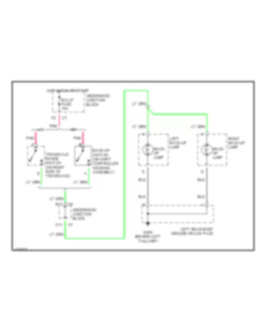
Backup Lamps Wiring Diagram for Saturn SC1 2000
 https://portal-diagnostov.com/license.html
Automotive Electricians Portal FZCO
Automotive Electricians Portal FZCO
https://portal-diagnostov.com/license.html
https://portal-diagnostov.com/license.html
Automotive Electricians Portal FZCO
Automotive Electricians Portal FZCOList of elements for Backup Lamps Wiring Diagram for Saturn SC1 2000:
- A/t
- B/u lp fuse 10a
- B11
- Back- up lamp
- Back-up switch (on shift controller housing assembly)
- C11
- G404 (behind left taillamp)
- Hot in run or start
- Left back-up lamp
- Left rear body ground splice pack
- M/t
- Pnk
- Right back-up lamp
- Transaxle range switch (on right side of transaxle)
- Underhood junction block
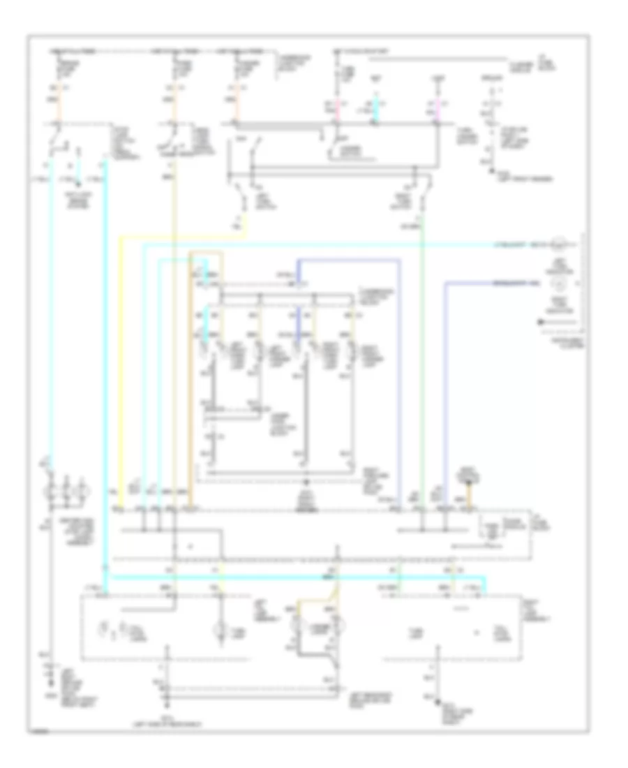
Exterior Lamps Wiring Diagram for Saturn SC1 2000
 https://portal-diagnostov.com/license.html
Automotive Electricians Portal FZCO
Automotive Electricians Portal FZCO
https://portal-diagnostov.com/license.html
https://portal-diagnostov.com/license.html
Automotive Electricians Portal FZCO
Automotive Electricians Portal FZCOList of elements for Exterior Lamps Wiring Diagram for Saturn SC1 2000:
- Anti-lock brake system
- B10
- B11
- B2 c3
- Bat
- Body control module
- Brake fuse 15a
- C3 c1
- Center high mounted stop lamp (chmsl) assembly
- Chime module
- F3 c1
- Flasher module
- G100 (left front fender)
- G101 (right front fender)
- G300
- G313 (right side of rear shelf)
- G314 (left side of rear shelf)
- Ground
- Hazard fuse 10a
- Hazard switch
- Head
- Head lamp/ turn signal switch
- Hot at all times
- Hot in run or start
- I/p fuse block
- I/p splice pack 1 (left side of dash)
- Instrument cluster
- Left body ground splice pack (below right front seat)
- Left front marker lamp
- Left front park/ turn lamp
- Left rear body ground splice pack
- Left tail lamp assembly
- Left turn indicator
- Left turn switch
- License lamps
- Load
- Off
- Park
- Park fuse 10a
- Park lps on
- Pnk
- Right forward lamp splice pack
- Right front marker lamp
- Right front park/ turn lamp
- Right tail lamp assembly
- Right turn indicator
- Right turn switch
- Stop lamp switch (on pedal support)
- Tail/ stop lamps
- Turn fuse 10a
- Turn lamp
- Turn/ hazard switch
- Under- hood junction block
- Underhood junction block
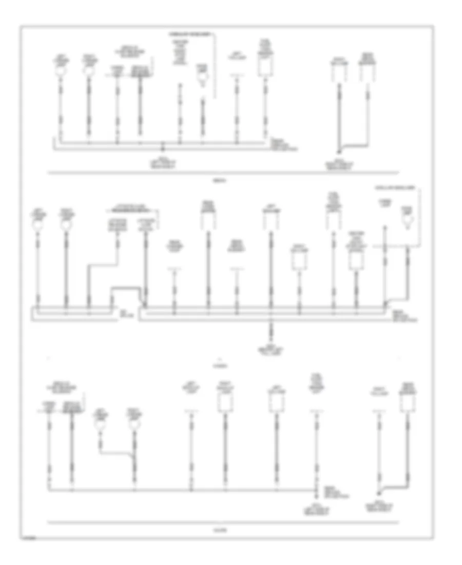
GROUND DISTRIBUTION
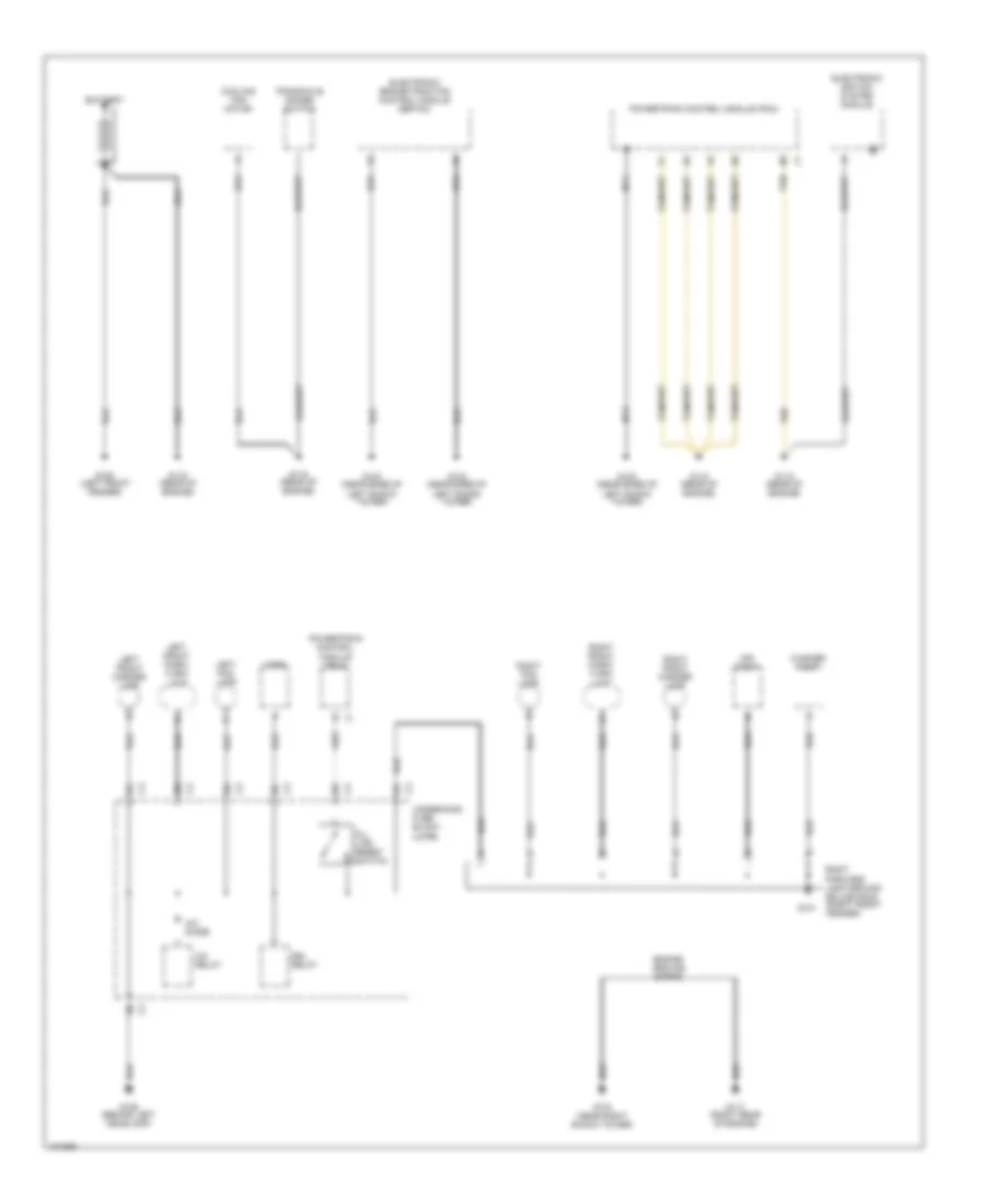
Ground Distribution Wiring Diagram (1 of 3) for Saturn SC1 2000
 https://portal-diagnostov.com/license.html
Automotive Electricians Portal FZCO
Automotive Electricians Portal FZCO
https://portal-diagnostov.com/license.html
https://portal-diagnostov.com/license.html
Automotive Electricians Portal FZCO
Automotive Electricians Portal FZCOList of elements for Ground Distribution Wiring Diagram (1 of 3) for Saturn SC1 2000:
- A/c diode
- A/c relay
- Air pump
- Battery
- Cooling fan motor
- Drl relay
- Electronic brake/traction control module (ebtcm)
- Electronic igntion system module
- Engine ground strap
- G100 (left front fender)
- G101
- G102 (near base of left shock tower)
- G103 (near right shock tower)
- G106 (behind left headlamp)
- G115 (rear of engine)
- G117 (right rear of engine)
- Horn
- Left fog lamp
- Left front marker lamp
- Left front park/ turn/ lamp
- Nca
- Oil life reset switch
- Powertrain control module (pcm)
- Right fog lamp
- Right forward lamp ground splice pack (right front fender)
- Right front marker lamp
- Right front park/ turn/ lamp
- Tan
- Transaxle range switch
- Underhood fuse block (uhfb)
- Washer pump
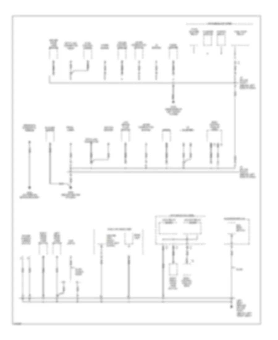
Ground Distribution Wiring Diagram (2 of 3) for Saturn SC1 2000
 https://portal-diagnostov.com/license.html
Automotive Electricians Portal FZCO
Automotive Electricians Portal FZCO
https://portal-diagnostov.com/license.html
https://portal-diagnostov.com/license.html
Automotive Electricians Portal FZCO
Automotive Electricians Portal FZCOList of elements for Ground Distribution Wiring Diagram (2 of 3) for Saturn SC1 2000:
- (below left front seat)
- A12
- B01
- B02
- B11
- Blower motor
- Body control module (bcm)
- Center high mount stoplight (chmsl)
- Cigar lighter
- Cruise control module
- Data link connector
- Data link connector (dlc)
- Dome lamp
- Driver door jamb switch
- Flasher module
- Fuel pump relay
- G102 (near base of left shock tower)
- G206 (behind center of dash)
- G302 (on parking brake bracket)
- Hvac blower relay
- Hvac control head
- I/p cluster
- I/p fuse block (ipfb)
- I/p splice pack 1 (behind left side of dash)
- I/p splice pack 2 (behind left side of dash)
- I/p switch
- Igntion switch
- Left body ground splice pack
- Left rear door jamb switch
- Lever combination switch
- Lock relay (door)
- Low brake fluid switch
- Map lights
- Modular headliner
- Nca
- Power window/ mirror switch
- Prndl lamp
- Radio
- Right front door jamb switch
- Right rear door jamb switch
- Sensing & diagnostic module
- Sl/sc
- Sl/sc (w/sun roof)
- Sun roof module
- Sun roof switch
- Unlock relay (door)
- Window relay
- Wiper motor
Ground Distribution Wiring Diagram (3 of 3) for Saturn SC1 2000
 https://portal-diagnostov.com/license.html
Automotive Electricians Portal FZCO
Automotive Electricians Portal FZCO
https://portal-diagnostov.com/license.html
https://portal-diagnostov.com/license.html
Automotive Electricians Portal FZCO
Automotive Electricians Portal FZCOList of elements for Ground Distribution Wiring Diagram (3 of 3) for Saturn SC1 2000:
- Cargo lamp
- Cargo lamp sw
- Center high mount stop lamp (chmsl)
- Center high mount stoplight (chmsl)
- Coupe
- Decklid ajar/ release solenoid
- Decklid release solenoid
- Dome lamp
- Fuel pump/ tank sensor unit
- G313 (right side of rear shelf)
- G314 (left side of rear shelf)
- G404 (behind left tail lamp)
- Idc splice
- Left back-up lamp
- Left license lamp
- Left taillamp
- Liftgate ajar switch
- Liftgate ajar/ release solenoid
- Liftgate release solenoid
- Modular headliner
- Rear defog element
- Rear ground splice pack
- Rear washer pump
- Rear wiper motor
- Right back-up lamp
- Right license lamp
- Right taillamp
- Sedan
- Wagon
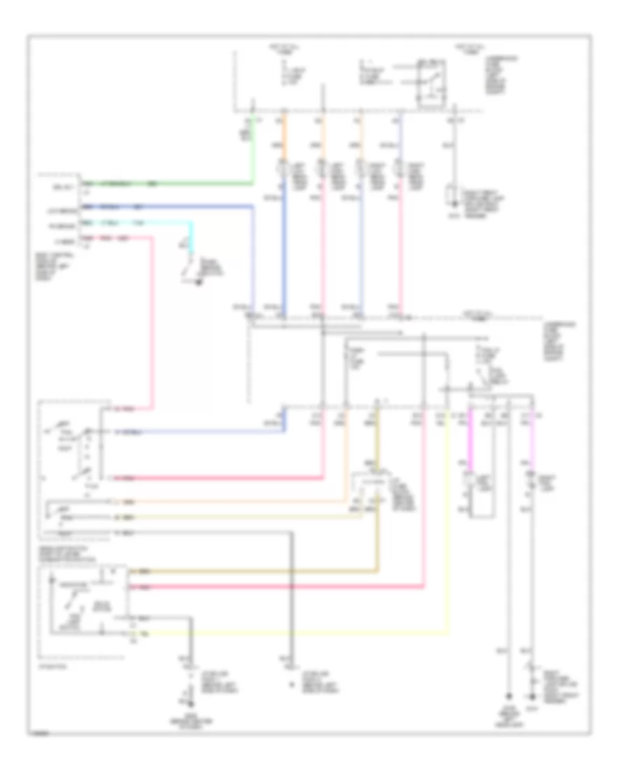
HEADLIGHTS
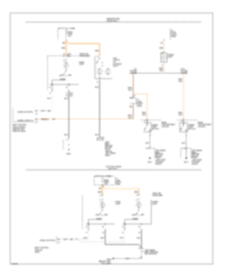
Headlight Wiring Diagram for Saturn SC1 2000
 https://portal-diagnostov.com/license.html
Automotive Electricians Portal FZCO
Automotive Electricians Portal FZCO
https://portal-diagnostov.com/license.html
https://portal-diagnostov.com/license.html
Automotive Electricians Portal FZCO
Automotive Electricians Portal FZCOList of elements for Headlight Wiring Diagram for Saturn SC1 2000:
- A04
- A06
- B02
- B08
- B11
- B12
- Body control module (behind left side of dash)
- C1 c3
- C1 d12
- C12
- C3 c11
- C3 f6
- Drl relay
- Drl rly
- E12
- E6 c1
- F-p
- F3 c1
- Fog lamp relay
- Fog lamp switch
- Fog lp fuse 10a
- G101
- G106 (behind left headlamp)
- G206 (behind center of dash)
- Hdlp
- Headlamp switch (part of lever combination switch)
- Hi beam
- Hot at all times
- I/p fuse block (behind center of dash)
- I/p splice pack 1 (behind left side of dash)
- I/p splice pack 2 (behind left side of dash)
- I/p switch
- Indicator
- L hdlp fuse 10a
- Left fog lamp
- Left high beam head- lamp
- Left low beam head- lamp
- Low beams
- Off
- Park brake switch
- Park lp fuse 10a
- Pk brake
- Pnk
- R hdlp fuse 10a
- Right fog lamp
- Right forward lamp splice pack (right front fender)
- Right front forward lamp splice pack (right front fender)
- Right high beam head- lamp
- Right low beam head- lamp
- Solid state
- Underhood fuse block (left side of engine compt)
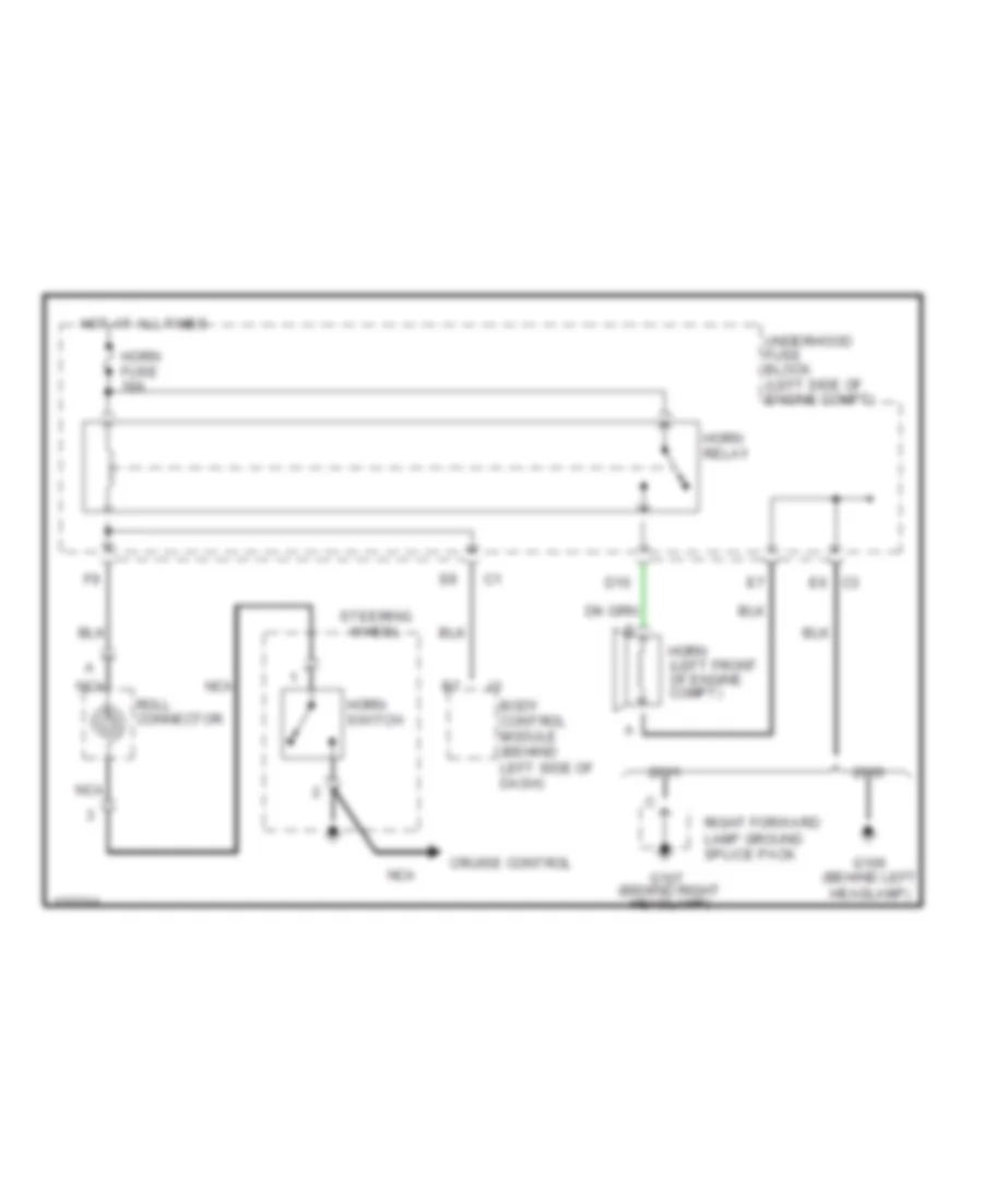
HORN
Horn Wiring Diagram for Saturn SC1 2000
 https://portal-diagnostov.com/license.html
Automotive Electricians Portal FZCO
Automotive Electricians Portal FZCO
https://portal-diagnostov.com/license.html
https://portal-diagnostov.com/license.html
Automotive Electricians Portal FZCO
Automotive Electricians Portal FZCOList of elements for Horn Wiring Diagram for Saturn SC1 2000:
- Body control module (behind left side of dash)
- Cruise control
- D10
- G106 (behind left headlamp)
- G107 (behind right headlamp)
- Horn (left front of engine compt)
- Horn fuse 10a
- Horn relay
- Horn switch
- Hot at all times
- Nca
- Right forward lamp ground splice pack
- Roll connector
- Steering wheel
- Underhood fuse block (left side of engine compt)
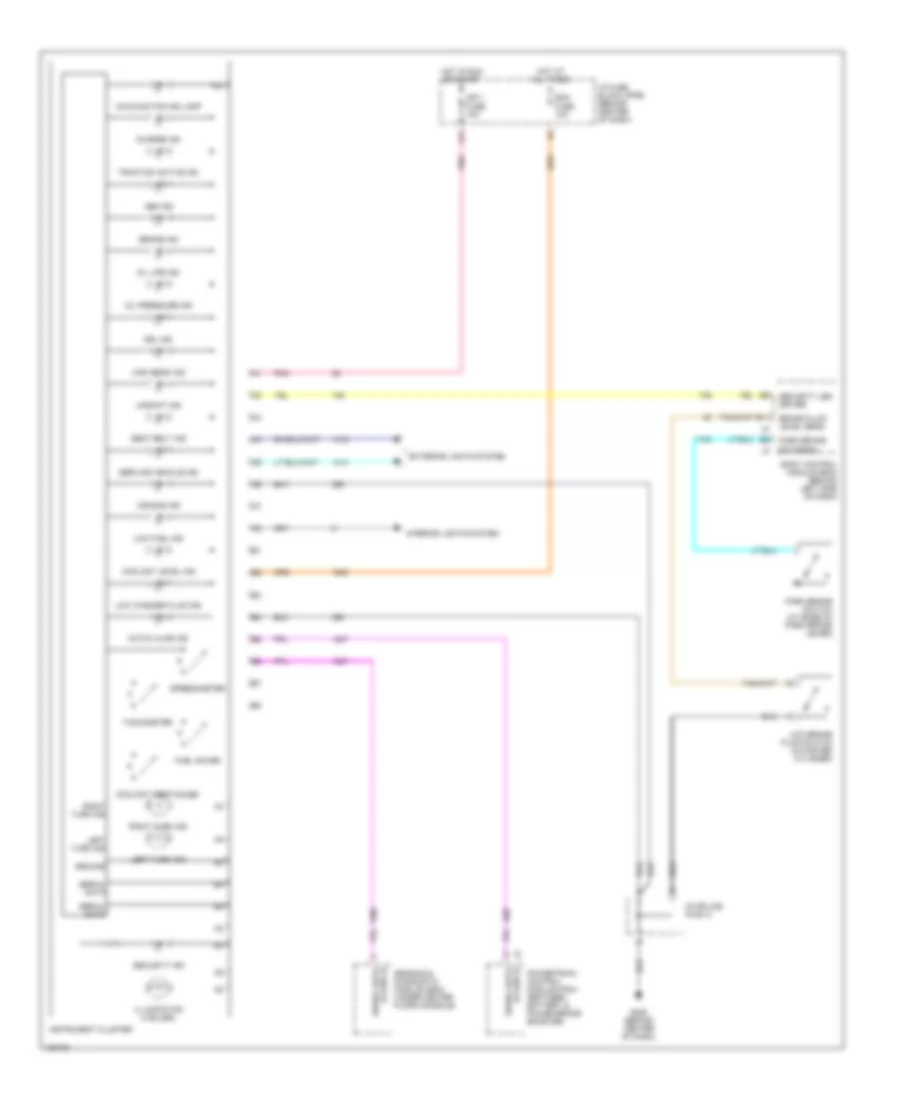
INSTRUMENT CLUSTER
Instrument Cluster Wiring Diagram for Saturn SC1 2000
 https://portal-diagnostov.com/license.html
Automotive Electricians Portal FZCO
Automotive Electricians Portal FZCO
https://portal-diagnostov.com/license.html
https://portal-diagnostov.com/license.html
Automotive Electricians Portal FZCO
Automotive Electricians Portal FZCOList of elements for Instrument Cluster Wiring Diagram for Saturn SC1 2000:
- A11
- Abs ind
- Air bag ind
- B11
- Bcm fuse 10a
- Body control module (bcm) (behind left side of dash)
- Brake fluid level sens
- Brake ind
- Charge ind
- Coolant level ind
- Coolant temp gauge
- Drl ind
- Exterior lights system
- Fuel gauge
- G206 (behind center of dash)
- Ground
- Hatch ajar ind
- High beam ind
- Hot at all times
- Hot in run or start
- I/p fuse block (ipfb) (behind center of dash)
- I/p splice pack 2
- Ign 1 fuse 10a
- Illumination (4 bulbs)
- Instrument cluster
- Interior lights system
- Left turn ind
- Low brake fluid switch (in master cylinder)
- Low fuel ind
- Low washer fluid ind
- Malfunction ind lamp
- Oil life ind
- Oil pressure ind
- Park brake sw signal
- Park brake switch (at base of park brake lever)
- Pnk
- Powertrain control module (pcm) (between battery & power brake booster)
- Right turn ind
- Seat belt ind
- Security ind
- Security led driver
- Sensing & diagnostic module (sdm) (under center floor console)
- Serial data
- Serial data (class 2)
- Service vehicle ind
- Speedometer
- Tachometer
- Traction active ind
- Upshift ind
INTERIOR LIGHTS
Interior Light Wiring Diagram (1 of 2) for Saturn SC1 2000
 https://portal-diagnostov.com/license.html
Automotive Electricians Portal FZCO
Automotive Electricians Portal FZCO
https://portal-diagnostov.com/license.html
https://portal-diagnostov.com/license.html
Automotive Electricians Portal FZCO
Automotive Electricians Portal FZCOList of elements for Interior Light Wiring Diagram (1 of 2) for Saturn SC1 2000:
- (left front fender)
- B11
- B12
- Body control module (bcm) (behind left side of dash)
- Dim high
- Dim low
- Dimmer
- G100
- G100 (left front fender)
- G206 (behind center of dash)
- G300
- Ground
- Head
- Headlamp
- Hot at all times
- Hvac control head
- I/p cluster
- I/p fuse block (ipfb)
- I/p splice pack (behind left side of dash)
- I/p splice pack 1 (behind left side of dash)
- I/p switch (dimmer)
- Left body ground splice pack (below left front seat)
- Left dr jamb in
- Left front door jamb switch
- Left rear door jamb switch (sl/sw only)
- Lever combination switch (lcs) (headlamp)
- Off
- Other dr jamb in
- Park
- Park lamp fuse 10a
- Park lamp input
- Power dim output
- Prndl lamp
- Radio
- Right front door jamb switch
- Right rear door jamb switch (sl/sw only)
- Underhood fuse block (uhfb)
Interior Light Wiring Diagram (2 of 2) for Saturn SC1 2000
 https://portal-diagnostov.com/license.html
Automotive Electricians Portal FZCO
Automotive Electricians Portal FZCO
https://portal-diagnostov.com/license.html
https://portal-diagnostov.com/license.html
Automotive Electricians Portal FZCO
Automotive Electricians Portal FZCOList of elements for Interior Light Wiring Diagram (2 of 2) for Saturn SC1 2000:
- (sc)
- (sc) (sl)
- (sl)
- (sw) only
- (w/ power locks)
- (w/o power locks)
- B c
- Body control module (bcm)
- Body control module (bcm) (behind left side of dash)
- Body fuse 10a
- Cargo lamp
- Cargo lamp switch
- Cargo lmp sw in
- Dome lamp
- Dome lmp cntrl
- Door
- E b
- G300
- G314
- G404 (behind left tail lamp)
- Hot at all times
- I/p fuse block (ipfb)
- Left body ground splice pack (below left front seat)
- Left rear body ground splice pack
- Left rear body ground splice pack (left side of rear shelf)
- Map lights (w/ sunroof only)
- Modular headliner
- Off
- Rear compartment lidlock
- Sedan/coupe (sl/sc) only
- Station wagon
POWER DISTRIBUTION
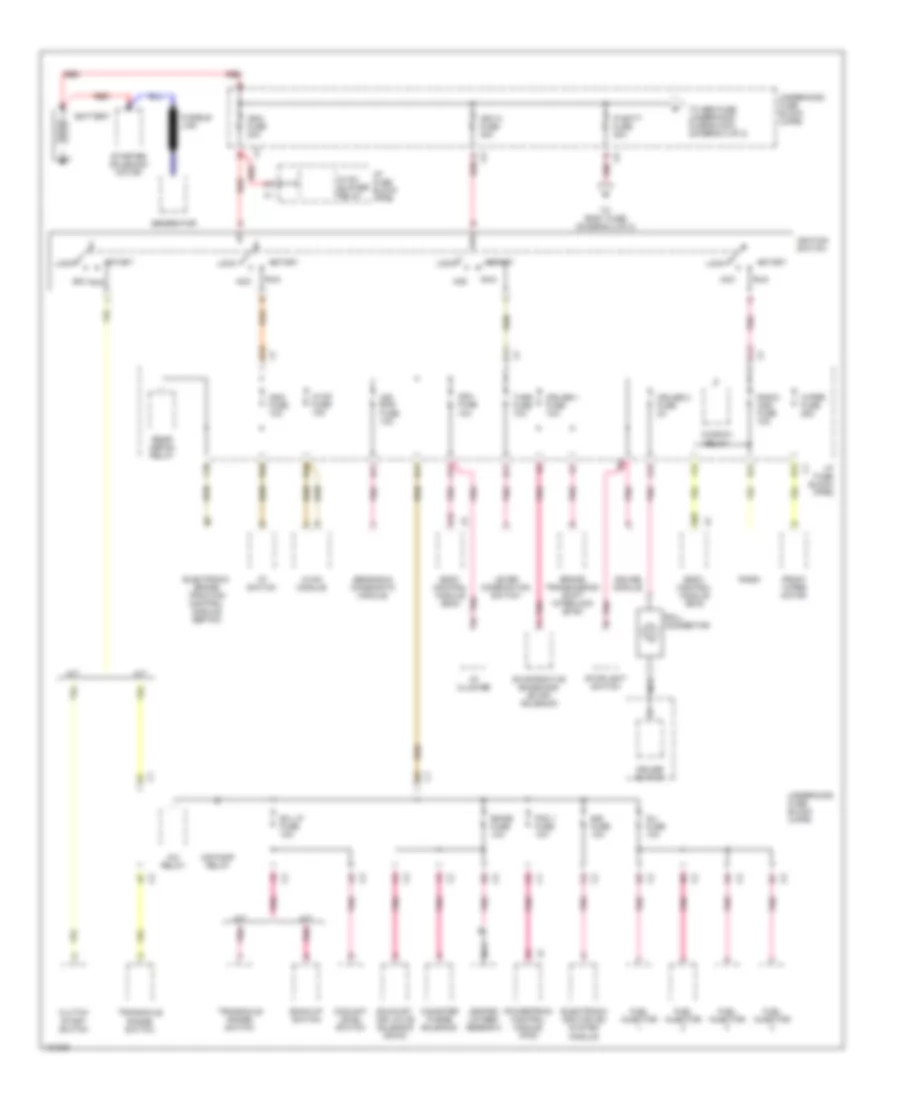
Power Distribution Wiring Diagram (1 of 2) for Saturn SC1 2000
 https://portal-diagnostov.com/license.html
Automotive Electricians Portal FZCO
Automotive Electricians Portal FZCO
https://portal-diagnostov.com/license.html
https://portal-diagnostov.com/license.html
Automotive Electricians Portal FZCO
Automotive Electricians Portal FZCOList of elements for Power Distribution Wiring Diagram (1 of 2) for Saturn SC1 2000:
- A/c relay
- A/t
- A03
- A11
- A12
- Acc
- Air bag fuse 10a
- Air pump relay
- B/u lp fuse 10a
- B10
- B11
- B12
- Back-up switch
- Battery
- Body control module (bcm)
- Brake transmission shift interlock (btsi)
- C11
- C12
- Canister purge solenoid
- Clutch start switch
- Coolant level switch
- Cruise 1 fuse 10a
- Cruise 2 fuse 2a
- Cruise module
- Cruise switch
- D10
- D11
- E10
- E11
- E12
- Eis fuse 10a
- Electronic brake traction control module (ebtcm)
- Electronic ignition (ei) system module
- Emiss fuse 10a
- Evaporative emissions (evap) solenoid
- Exhaust air valve solenoid (dohc)
- F10
- F12
- Front wiper motor
- Fuel injector
- Fusible link
- Generator
- Heated oxygen sensor 2
- Hvac blower relay
- Hvac fuse 15a
- Hvac module
- I/p cluster
- I/p fuse block (ipfb)
- I/p switch
- Ign1 fuse 10a
- Ign1/4 fuse 30a
- Ign3 fuse 10a
- Ign3 fuse 30a
- Ignition switch
- Inj fuse 10a
- Ip batt fuse 30a
- Lever combination switch
- Lock
- M/t
- Nca
- Pcm 1 fuse 10a
- Pnk
- Powertrain control module (pcm)
- Radio
- Radio (ign) fuse 10a
- Rear defog relay
- Red
- Roll connector
- Run
- Sensing & diagnostic module
- Start
- Starter solenoid/ motor
- Stoplight switch
- To abs fuse (underhood fuse block) (diagram 2 of 2)
- To body fuse (diagram 2 of 2)
- Transaxle range switch
- Turn fuse 10a
- Underhood fuse block (uhfb)
- Window relay
- Wiper fuse 25a
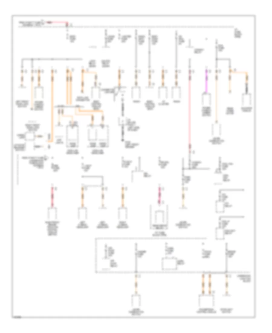
Power Distribution Wiring Diagram (2 of 2) for Saturn SC1 2000
 https://portal-diagnostov.com/license.html
Automotive Electricians Portal FZCO
Automotive Electricians Portal FZCO
https://portal-diagnostov.com/license.html
https://portal-diagnostov.com/license.html
Automotive Electricians Portal FZCO
Automotive Electricians Portal FZCOList of elements for Power Distribution Wiring Diagram (2 of 2) for Saturn SC1 2000:
- A/c fuse 10a
- A/c relay
- A10
- A11
- Abs fuse 50a
- Air pump fuse 30a
- Air pump relay
- B (sc) (sl)
- B01
- B03
- B10
- Body comp fuse 10a
- Body control module (bcm)
- Body fuse 10a
- Brake fuse 15a
- Cargo lamp
- Cd (ria) fuse 5a
- Cigarette lighter
- Cool fan fuse 30a
- Cool fan relay
- Data link connector
- Dome lamp
- Drl relay
- Electronic brake/ traction control module (ebtcm)
- Fog lp fuse 10a
- Foglight relay
- From ip batt fuse a (diagram 1 of 2)
- From ip batt fuse b (underhood fuse block) (diagram 1 of 2)
- G100 (left front fender)
- Hazard fuse 10a
- Horn fuse 10a
- Horn relay
- I/p fuse block (ipfb)
- I/p cluster
- I/p fuse block (ipfb)
- I/p splice pack 1 (left side of dash)
- L hdlp fuse 10a
- Left front door lock switch
- Left hi beam headlamp
- Left lo beam headlamp
- Lever combination switch
- Liftgate release switch
- Lighter fuse 20a
- Lock relay (door)
- Locks fuse 20a
- Map lights
- Modular headliner
- Nca
- Park fuse 10a
- Pcm b fuse 10a
- Pnk
- Power window/ mirror switch
- Powertrain control module
- R hdlp fuse 10a
- Radio
- Radio (bat) fuse 10a
- Rear defog relay
- Rear wiper motor
- Red
- Right front door lock switch
- Right lo beam headlamp
- Rr dfg fuse 30a
- Sl/sc
- Stoplight switch
- Sun fuse 15a
- Sun roof module
- Underhood junction block
- Unlock relay (door)
- Window fuse 30a
- Window relay
POWER DOOR LOCKS
Power Door Lock Wiring Diagram for Saturn SC1 2000
 https://portal-diagnostov.com/license.html
Automotive Electricians Portal FZCO
Automotive Electricians Portal FZCO
https://portal-diagnostov.com/license.html
https://portal-diagnostov.com/license.html
Automotive Electricians Portal FZCO
Automotive Electricians Portal FZCOList of elements for Power Door Lock Wiring Diagram for Saturn SC1 2000:
- A03
- A04
- A06
- A10
- A11
- A12
- All doors lock
- All other doors unlk
- All other dr jamb in
- B01
- B05
- B07
- B09
- B10
- B11
- B12
- Battery
- Body comp fuse 10a
- Body control module (behind left side of dash)
- Body fuse 10a
- C1 c1
- C1 c9
- C12
- C2 c10
- C2 d3
- C2 f10
- C3 c5
- C3 d5
- D12
- Data link connector (under left side of dash)
- Dome lamp ctrl
- Driver door jamb in
- Driver door jamb switch
- Driver door unlk
- E10
- E12
- F12
- G100 (left front fender)
- G206 (behind center of dash)
- G300
- G404 (behind left tail lamp)
- Ground
- Horn relay ctrl
- Horn system
- Hot at all times
- I/p fuse block (behind center of dash)
- I/p splice pack 1 (behind left side of dash)
- I/p splice pack 2 (behind left side of dash)
- Interior lights system
- Left body ground splice pack (below left front seat)
- Left front door lock motor
- Left front door lock switch
- Left rear body ground splice pack
- Left rear door jamb switch
- Left rear door lock motor
- Liftgate ajar in
- Liftgate ajar switch
- Liftgate latch
- Lock
- Lock relay
- Locks fuse 20a
- Right front door jamb switch
- Right front door lock motor
- Right front door lock switch
- Right rear door jamb switch
- Right rear door lock motor
- Serial data
- Tan
- Unlock
- Unlock relay
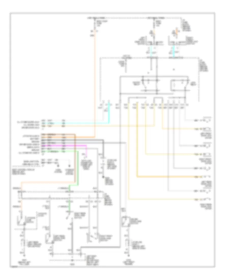
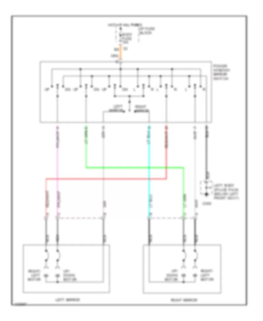
POWER MIRRORS
Power Mirror Wiring Diagram for Saturn SC1 2000
 https://portal-diagnostov.com/license.html
Automotive Electricians Portal FZCO
Automotive Electricians Portal FZCO
https://portal-diagnostov.com/license.html
https://portal-diagnostov.com/license.html
Automotive Electricians Portal FZCO
Automotive Electricians Portal FZCOList of elements for Power Mirror Wiring Diagram for Saturn SC1 2000:
- Body fuse 10a
- C2 b8
- G300
- Hot at all times
- I/p fuse block
- Left body splice pack (below left front seat)
- Left mirror
- Nca
- Power window/ mirror switch
- Right mirror
- Right/ left motor
- Up/ down motor
POWER TOP/SUNROOF
Power Top/Sunroof Wiring Diagrams for Saturn SC1 2000
 https://portal-diagnostov.com/license.html
Automotive Electricians Portal FZCO
Automotive Electricians Portal FZCO
https://portal-diagnostov.com/license.html
https://portal-diagnostov.com/license.html
Automotive Electricians Portal FZCO
Automotive Electricians Portal FZCOList of elements for Power Top/Sunroof Wiring Diagrams for Saturn SC1 2000:
- (front center of roof) sun roof module
- A10
- Close
- G100 (left front fender)
- G300 (below left front seat)
- Hot at all times
- Hot in acc & run
- I/p fuse block (behind center of dash)
- I/p splice pack 1 (behind left side of dash)
- Left body ground splice pack
- Limit switch
- Nca
- Off
- Open
- Power distribution system
- Red
- Sun fuse 15a
- Sun roof switch
- Sunroof motor
- Underhood fuse block (on left side of engine compt)
- Vent
- Window fuse 30a
- Window relay
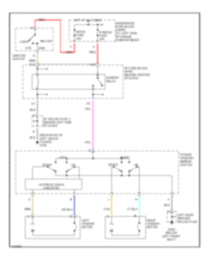
POWER WINDOWS
Power Window Wiring Diagram for Saturn SC1 2000
 https://portal-diagnostov.com/license.html
Automotive Electricians Portal FZCO
Automotive Electricians Portal FZCO
https://portal-diagnostov.com/license.html
https://portal-diagnostov.com/license.html
Automotive Electricians Portal FZCO
Automotive Electricians Portal FZCOList of elements for Power Window Wiring Diagram for Saturn SC1 2000:
- (near base of left shock tower) g102
- A10
- Acc
- C12
- Down
- Express down circuitry
- G300 (below left front seat)
- Hot at all times
- I/p fuse block (ipfb) (behind center of dash)
- I/p splice pack 1 (behind left side of dash)
- Ign1/4 fuse 30a
- Ignition switch
- Left
- Left body ground splice pack
- Left window motor
- Lock
- Power window/ mirror switch
- Red
- Right
- Right window motor
- Run
- Start
- Tan
- Underhood fuse block (uhfb) (at left side of engine compartment)
- Window fuse 30a
- Window relay
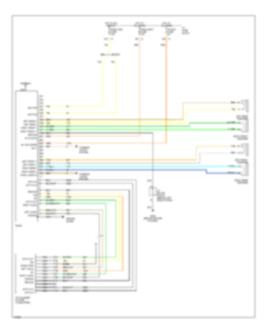
RADIO
Radio Wiring Diagrams for Saturn SC1 2000
 https://portal-diagnostov.com/license.html
Automotive Electricians Portal FZCO
Automotive Electricians Portal FZCO
https://portal-diagnostov.com/license.html
https://portal-diagnostov.com/license.html
Automotive Electricians Portal FZCO
Automotive Electricians Portal FZCOList of elements for Radio Wiring Diagrams for Saturn SC1 2000:
- A01
- A02
- A03
- A04
- A05
- A06
- A07
- A08
- A09
- A10
- A11
- A12
- Antenna
- B+ (cd chngr)
- B+ (clock)
- B01
- B02
- B03
- B04
- B05
- B06
- B07
- B08
- B09
- B10
- B11
- B12
- B12 c1
- Bare
- Cd (ria) fuse 5a
- Cd changer/ player (if equipped)
- Common
- Data clk
- Data in
- Data out
- Dim +
- E5 c1
- G206 (behind center of dash)
- Ground
- Ground strap
- Hot at all times
- Hot in acc or run
- I/p fuse block
- I/p splice pack 2 (behind left side of dash)
- Ign
- Ignition
- Interior lights system
- Left audio
- Left front +
- Left front -
- Left front speaker
- Left rear +
- Left rear -
- Left rear speaker
- Nca
- Park lamps in
- Radio
- Radio (bat) fuse 10a
- Radio (ign) fuse 10a
- Right audio
- Right front +
- Right front -
- Right front speaker
- Right rear +
- Right rear -
- Right rear speaker
- Sc & sl
- Shield gnd
- Tan
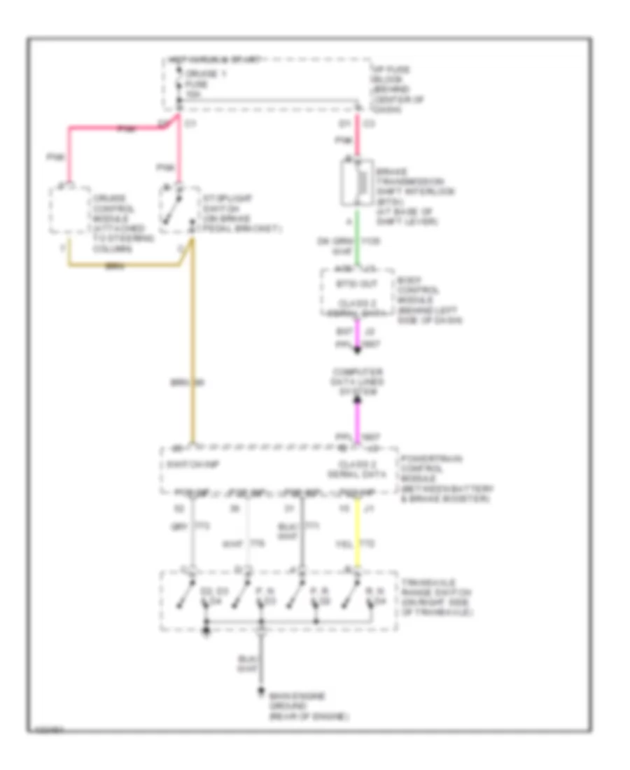
SHIFT INTERLOCKS
Shift Interlock Wiring Diagram for Saturn SC1 2000
 https://portal-diagnostov.com/license.html
Automotive Electricians Portal FZCO
Automotive Electricians Portal FZCO
https://portal-diagnostov.com/license.html
https://portal-diagnostov.com/license.html
Automotive Electricians Portal FZCO
Automotive Electricians Portal FZCOList of elements for Shift Interlock Wiring Diagram for Saturn SC1 2000:
- A05
- B07
- Body control module (behind left side of dash)
- Brake transmission shift interlock (btsi) (at base of shift lever)
- Btsi out
- Class 2 serial data
- Computer data lines system
- Cruise 1 fuse 10a
- Cruise control module (attached to steering column)
- D2, d3 & d4
- Hot in run & start
- I/p fuse block (behind center of dash)
- Main engine ground (rear of engine)
- P, n & d3
- P, r & d2
- Pnk
- Pos inp
- Powertrain control module (between battery & brake booster)
- R, n & d4
- Stoplight switch (on brake pedal bracket)
- Switch inp
- Transaxle range switch (on right side of transaxle)
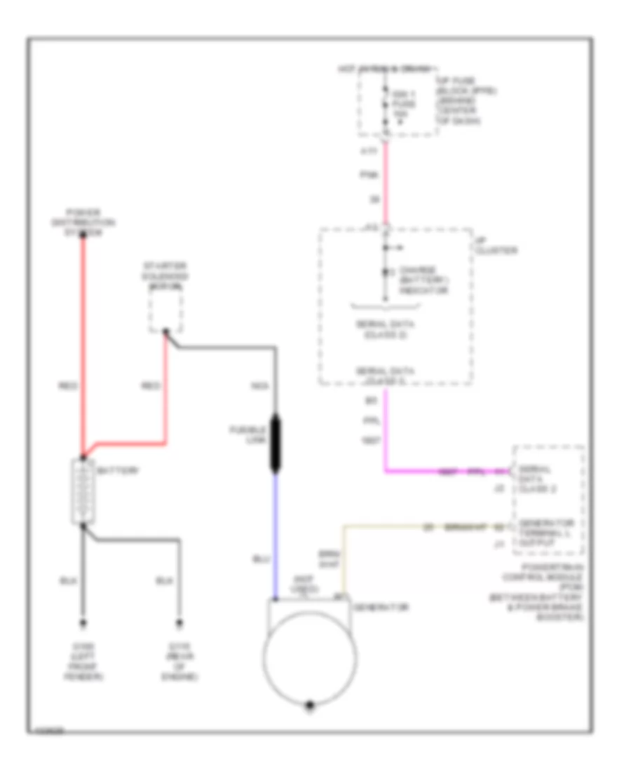
STARTING/CHARGING
Charging Wiring Diagram for Saturn SC1 2000
 https://portal-diagnostov.com/license.html
Automotive Electricians Portal FZCO
Automotive Electricians Portal FZCO
https://portal-diagnostov.com/license.html
https://portal-diagnostov.com/license.html
Automotive Electricians Portal FZCO
Automotive Electricians Portal FZCOList of elements for Charging Wiring Diagram for Saturn SC1 2000:
- (not used)
- A11
- Battery
- Charge (battery) indicator
- Fusible link
- G100 (left front fender)
- G115 (rear of engine)
- Generator
- Generator terminal l output
- Hot in run & crank
- I/p cluster
- I/p fuse block (ipfb) (behind center of dash)
- Ign 1 fuse 10a
- Nca
- Pnk
- Power distribution system
- Powertrain control module (pcm) (between battery & power brake booster)
- Red
- Serial data (class 2)
- Serial data class 2
- Starter solenoid/ motor
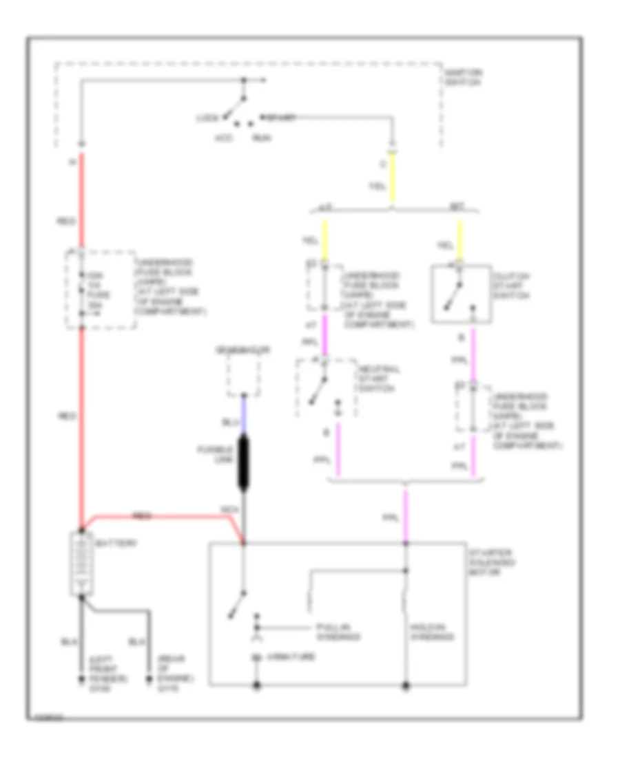
Starting Wiring Diagram for Saturn SC1 2000
 https://portal-diagnostov.com/license.html
Automotive Electricians Portal FZCO
Automotive Electricians Portal FZCO
https://portal-diagnostov.com/license.html
https://portal-diagnostov.com/license.html
Automotive Electricians Portal FZCO
Automotive Electricians Portal FZCOList of elements for Starting Wiring Diagram for Saturn SC1 2000:
- (left front fender) g100
- (rear of engine) g115
- A/t
- Acc
- Armature m
- Battery
- Clutch start switch
- Fusible link
- Generator
- Hold-in windings
- Ign 1/4 fuse 30a
- Ignition switch
- Lock
- M/t
- Nca
- Neutral start switch
- Pull-in windings
- Red
- Run
- Start
- Starter solenoid/ motor
- Underhood fuse block (uhfb) (at left side of engine c0mpartment)
- Underhood fuse block (uhfb) (at left side of engine compartment)
SUPPLEMENTAL RESTRAINTS
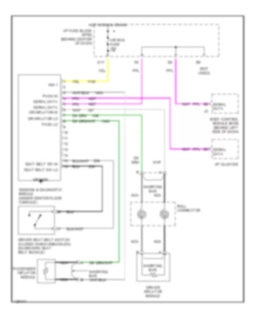
Supplemental Restraint Wiring Diagram for Saturn SC1 2000
 https://portal-diagnostov.com/license.html
Automotive Electricians Portal FZCO
Automotive Electricians Portal FZCO
https://portal-diagnostov.com/license.html
https://portal-diagnostov.com/license.html
Automotive Electricians Portal FZCO
Automotive Electricians Portal FZCOList of elements for Supplemental Restraint Wiring Diagram for Saturn SC1 2000:
- (not used)
- Air bag fuse 10a
- Body control module (bcm) (behind left side of dash)
- Dr inflator hi
- Dr inflator lo
- Driver inflator module
- Driver seat belt switch (closed when unbuckled) (in driver's seat belt buckle)
- E11
- Ground
- Hot in run & crank
- I/p cluster
- I/p fuse block (ipfb) (behind center of dash)
- Ign 1
- Nca
- Pass hi
- Pass lo
- Passenger inflator module
- Roll connector
- Seat belt sw hi
- Seat belt sw lo
- Sensing & diagnostic module (under center floor console)
- Serial data
- Shorting bar
TRANSMISSION
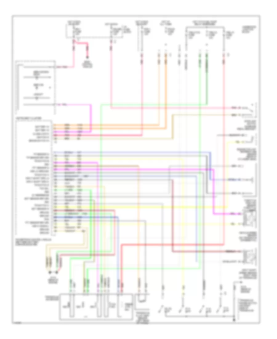
A/T Wiring Diagram for Saturn SC1 2000
 https://portal-diagnostov.com/license.html
Automotive Electricians Portal FZCO
Automotive Electricians Portal FZCO
https://portal-diagnostov.com/license.html
https://portal-diagnostov.com/license.html
Automotive Electricians Portal FZCO
Automotive Electricians Portal FZCOList of elements for A/T Wiring Diagram for Saturn SC1 2000:
- 5v reference
- A11
- Battery in
- Body control module
- Brake switch in
- Class 2 data
- Cruise fuse 10a
- D2, d3 & d4
- Ect sensor in
- Ect sensor return
- Engine coolant temperature sensor (rear of cylinder head)
- G115 (rear of engine)
- Ground
- Hot at all times
- Hot in run
- Hot in run or start
- Hot with fuel pump relay energized
- I/p fuse block
- Ign 1 fuse 10a
- Ignition in
- Input shaft spd hi
- Input shaft spd lo
- Input shaft speed sensor (right side of transaxle)
- Instrument cluster
- P, n & d3
- P, r & d2
- Pcm 1 fuse 10a
- Pcm b fuse 10a
- Pcs
- Pnk
- Powertrain control module (between battery & brake booster)
- Press ctrl sol
- R, n & d4
- Red
- Service
- Service eng soon
- Ss2
- Ss3
- Ss4
- Stoplamp switch (on brake pedal bracket)
- Tcc sol
- Tft sensor in
- Tft sensor return
- Throttle position sensor (throttle body)
- Tp sensor in
- Tp sensor return
- Tr switch a
- Tr switch b
- Tr switch c
- Tr switch d
- Transaxle fluid temp sensor (left rear of trans)
- Transaxle range switch (on right side of transaxle)
- Transaxle solenoids
- Trs 2/tcc fuse 10a
- Trs 3/4 fuse 10a
- Trs lp fuse 10a
- Underhood junction block
- Upshift
- Vehicle speed sensor (on transaxle differential)
- Vss hi (signal)
- Vss lo (ground)
TRUNK, TAILGATE, FUEL DOOR
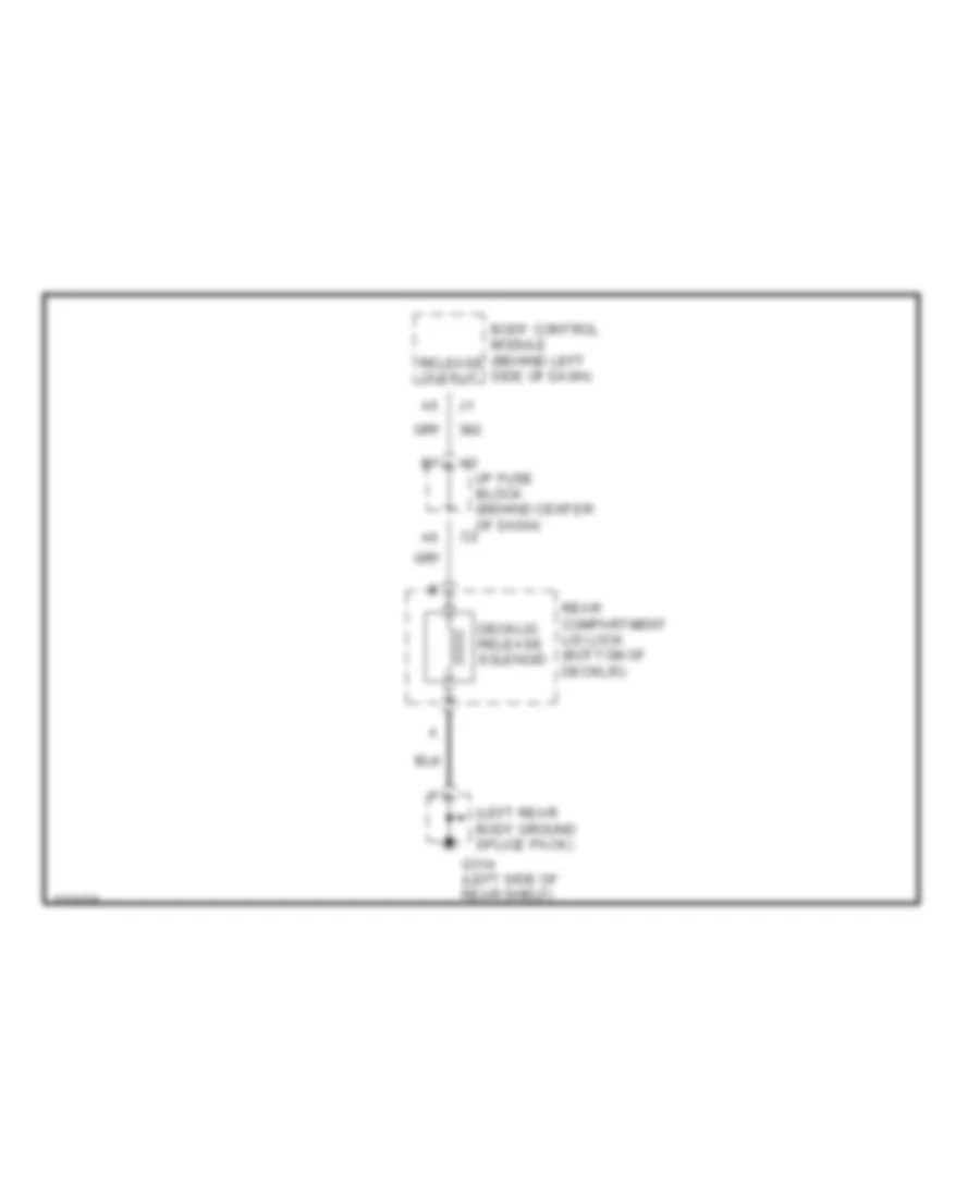
Trunk Release Wiring Diagram for Saturn SC1 2000
 https://portal-diagnostov.com/license.html
Automotive Electricians Portal FZCO
Automotive Electricians Portal FZCO
https://portal-diagnostov.com/license.html
https://portal-diagnostov.com/license.html
Automotive Electricians Portal FZCO
Automotive Electricians Portal FZCOList of elements for Trunk Release Wiring Diagram for Saturn SC1 2000:
- (left rear body ground splice pack)
- Body control module (behind left side of dash)
- Decklid release solenoid
- G314 (left side of rear shelf)
- I/p fuse block (behind center of dash)
- Rear compartment lid lock (bottom of decklid)
- Release output
WARNING SYSTEMS
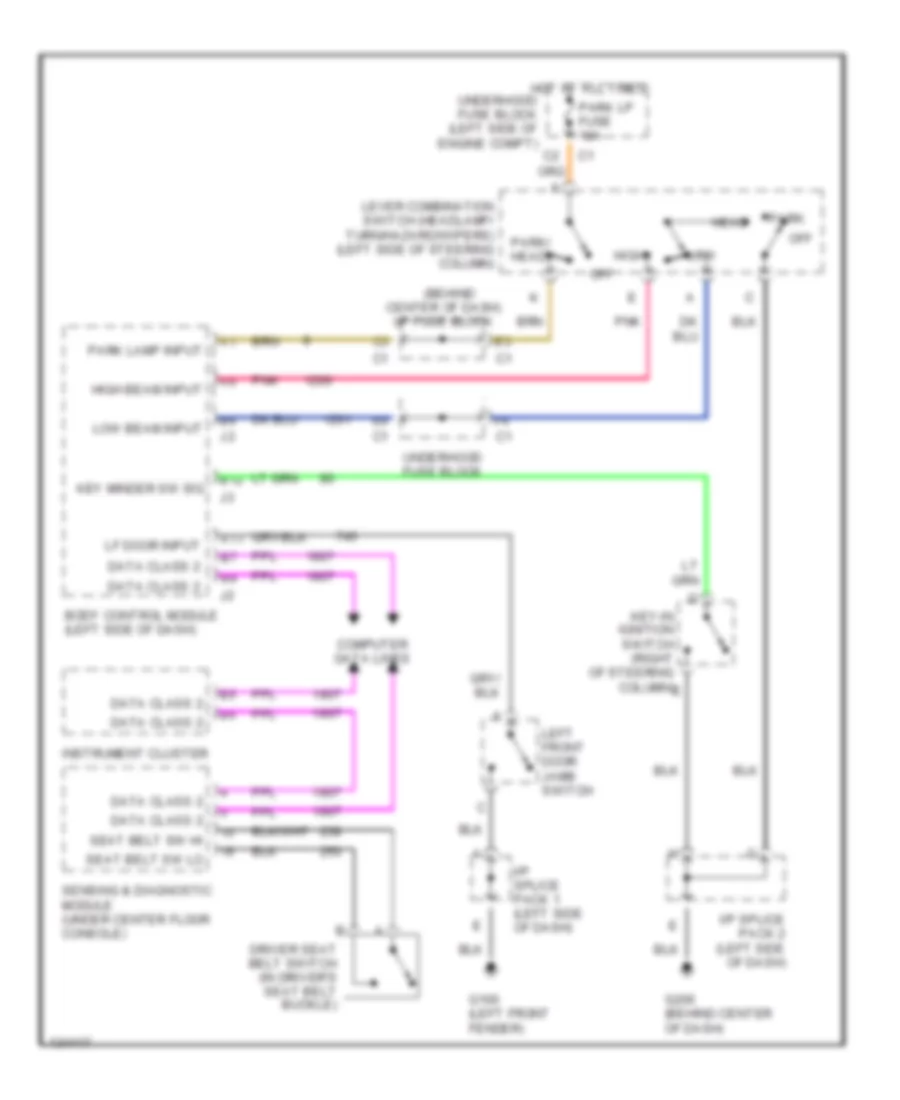
Warning System Wiring Diagrams for Saturn SC1 2000
 https://portal-diagnostov.com/license.html
Automotive Electricians Portal FZCO
Automotive Electricians Portal FZCO
https://portal-diagnostov.com/license.html
https://portal-diagnostov.com/license.html
Automotive Electricians Portal FZCO
Automotive Electricians Portal FZCOList of elements for Warning System Wiring Diagrams for Saturn SC1 2000:
- (behind center of dash) i/p fuse block
- A11
- B12
- Body control module (left side of dash)
- Computer data lines
- Data class 2
- Driver seat belt switch (in driver's seat belt buckle)
- G100 (left front fender)
- G206 (behind center of dash)
- Head
- High
- High beam input
- Hot at all times underhood fuse block (left side of engine compt)
- I/p splice pack 1 (left side of dash)
- I/p splice pack 2 (left side of dash)
- Instrument cluster
- Key minder sw sig
- Key-in ignition switch (right of steering column) e
- Left front door jamb switch
- Lever combination switch (headlamp/ turn/hazard/wipers) (left side of steering column)
- Lf door input
- Low
- Low beam input
- Off
- Park
- Park lamp input
- Park lp fuse 10a
- Park/ head
- Pnk
- Seat belt sw hi
- Seat belt sw lo
- Sensing & diagnostic module (under center floor console)
- Underhood fuse block
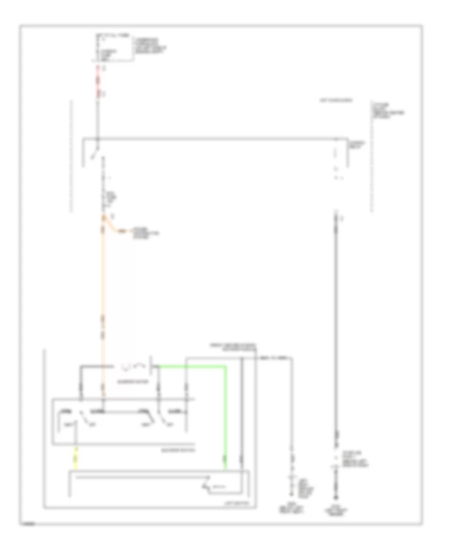
WIPER/WASHER
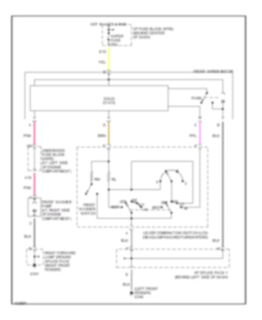
Wiper/Washer Wiring Diagram for Saturn SC1 2000
 https://portal-diagnostov.com/license.html
Automotive Electricians Portal FZCO
Automotive Electricians Portal FZCO
https://portal-diagnostov.com/license.html
https://portal-diagnostov.com/license.html
Automotive Electricians Portal FZCO
Automotive Electricians Portal FZCOList of elements for Wiper/Washer Wiring Diagram for Saturn SC1 2000:
- (left front fender) g100
- A10
- E12
- Front washer pump (at right side of engine compartment)
- Front washer switch
- Front wiper motor
- G101
- Hot in accy & run
- I/p fuse block (ipfb) (behind center of dash)
- I/p splice pack 1 (behind left side of dash)
- Int
- Lever combination switch (lcs) (headlamp/hazard/turn/wipers)
- Mist
- Off
- Park
- Pnk
- Right forward lamp ground splice pack (right front fender)
- Solid state
- Underhood fuse block (uhfb) (at left side of engine compartment)
- Wiper fuse 25a

 Čeština
 Dansk
Dansk Deutsch
 Ελληνικά
 English
 English
 Español
 Suomi
Suomi Français
 Français
 עברית
עברית Hrvatski
 Magyar
 Italiano
 한국어
한국어 Nederlands
 Polski
 Português
 Português
 Română
 Русский
 Slovenčina
 Slovenščina
 Svenska
 Türkçe
 中文 (中国)
