AIR CONDITIONING
2.2L VIN D
2.2L VIN D, Compressor Wiring Diagram for Saturn Vue Red Line 2007
 https://portal-diagnostov.com/license.html
Automotive Electricians Portal FZCO
Automotive Electricians Portal FZCO
https://portal-diagnostov.com/license.html
https://portal-diagnostov.com/license.html
Automotive Electricians Portal FZCO
Automotive Electricians Portal FZCO
List of elements for 2.2L VIN D, Compressor Wiring Diagram for Saturn Vue Red Line 2007:
- (right side of engine compt) engine control module (ecm)
- 5v ref
- A/c clutch fuse 10a
- A/c clutch relay
- A/c compressor clutch (at lower left front of engine)
- A/c diode
- A/c press sens
- A/c refrigerant pressure sensor (in a/c high side pressure line)
- A/c req sig
- A/c request
- A12
- A6 c1
- A6 c2
- B12
- Body control module (bcm) (below front of center floor console)
- Bus +
- Bus -
- Clu rly ctrl
- Computer data lines system
- E10
- E11
- Evap temp sens
- Evaporator temperature sensor
- G101
- Hot at all times
- Hot in run or start
- Hvac control module
- Logic
- Low ref
- Low reference
- Splice pack sp101 (behind left front headlight)
- Tan
- Underhood fuse block (left side of engine compt)
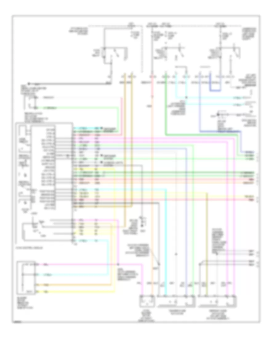
2.2L VIN D, Manual A/C Wiring Diagram (1 of 2) for Saturn Vue Red Line 2007
 https://portal-diagnostov.com/license.html
Automotive Electricians Portal FZCO
Automotive Electricians Portal FZCO
https://portal-diagnostov.com/license.html
https://portal-diagnostov.com/license.html
Automotive Electricians Portal FZCO
Automotive Electricians Portal FZCOList of elements for 2.2L VIN D, Manual A/C Wiring Diagram (1 of 2) for Saturn Vue Red Line 2007:
- (at left front of engine compt) cooling fan resistor
- (in hvac harness, between c202 & panel mode actuator harness breakout)
- (in hvac harness, between defrost mode & panel mode actuator harness breakout) s206
- 5v ref
- A/c on ind
- A/c req sig
- A/c sw sig
- A10 c1
- B c5
- B11
- B11 c3
- Blower motor resistor (at right side of hvac)
- C2 c1
- Cold ctrl
- Cool fan hi relay
- Cool fan low relay
- Cool hi fuse 40a
- Cool lo fuse 20a
- Cooling fan (behind radiator)
- Ctrl a
- Ctrl b
- D2 c2
- D9 c3
- Defog ind
- Defogger system
- Defrost mode actuator (on left side of hvac assembly)
- F12 c2
- G101
- G201
- G203 (near lower center of dash, on i/p fuse block)
- Ground
- High
- Hot at all times
- Hot ctrl
- Hot in run
- Hvac blo relay
- Hvac blower fuse 40a
- Hvac blower motor (at right side of hvac)
- Hvac control module
- Hvac fuse 10a
- I/p fuse block (behind center of dash)
- Ign 3 vol
- Interior lights system
- Logic
- Low ctrl
- Low ref
- Mode switch
- Off
- Position sig
- Recircu- lation ind
- Recircu- lation sw
- Recirculation actuator (on lower front of hvac assembly)
- Red
- S111 (in forward light harness, near underhood fuse block)
- S205 (in i/p harness, between hvac & radio harness breakout)
- S207
- Sensor sig
- Sol ctrl a
- Sol ctrl b
- Splice pack sp101 (behind left front headlight)
- Splice pack sp201 (behind right front kick panel)
- Supp volt
- Sw sig
- Tan
- Temp ctrl
- Temperature actuator
- Underhood fuse block (left side of engine compt)
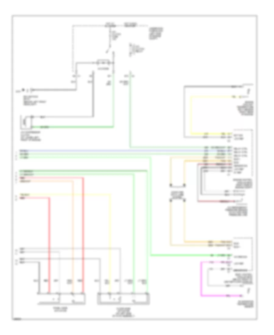
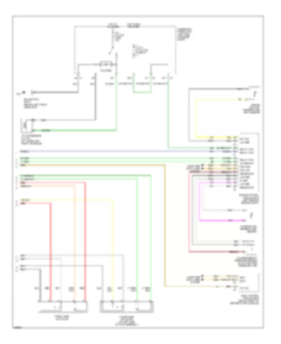
2.2L VIN D, Manual A/C Wiring Diagram (2 of 2) for Saturn Vue Red Line 2007
 https://portal-diagnostov.com/license.html
Automotive Electricians Portal FZCO
Automotive Electricians Portal FZCO
https://portal-diagnostov.com/license.html
https://portal-diagnostov.com/license.html
Automotive Electricians Portal FZCO
Automotive Electricians Portal FZCOList of elements for 2.2L VIN D, Manual A/C Wiring Diagram (2 of 2) for Saturn Vue Red Line 2007:
- 5v ref
- A/c clutch fuse 10a
- A/c clutch relay
- A/c compressor clutch (at lower left front of engine)
- A/c diode
- A/c refrigerant pressure sensor (in a/c high side pressure line)
- A/c req sig
- A12
- A6 c1
- B12
- Body control module (bcm) (below front of center floor console)
- Bus +
- Bus -
- Computer data lines system
- E10
- E11
- Ect sig
- Engine control module (ecm) (right side of engine compt)
- Engine coolant temperature (ect) sensor (right rear of engine)
- Evaporator temperature sensor
- Floor mode actuator (on left side of hvac assembly)
- G101
- Hot at all times
- Hot in run or start
- Low ref
- Panel mode actuator
- Red
- Relay ctrl
- Sensor sig
- Splice pack sp101 (behind left front headlight)
- Tan
- Underhood fuse block (left side of engine compt)
2.4L VIN Z
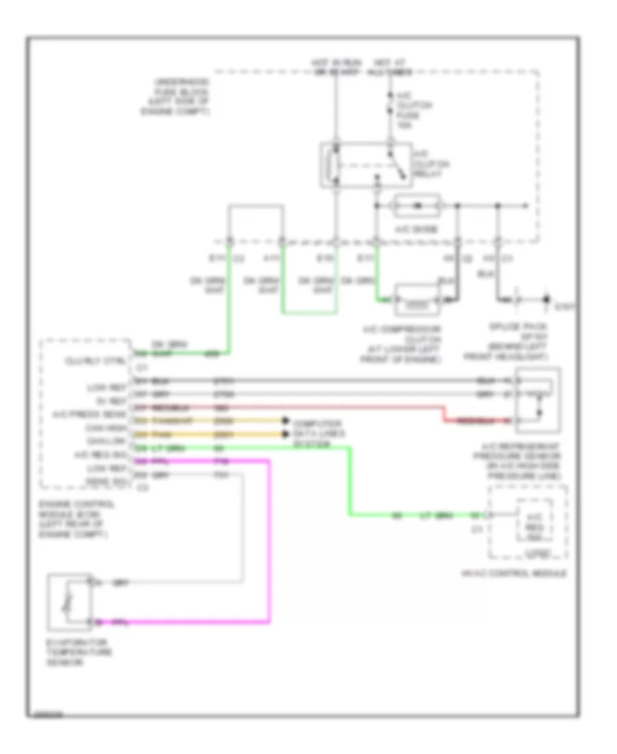
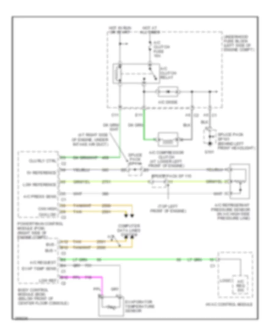
2.4L VIN Z, Compressor Wiring Diagram for Saturn Vue Red Line 2007
 https://portal-diagnostov.com/license.html
Automotive Electricians Portal FZCO
Automotive Electricians Portal FZCO
https://portal-diagnostov.com/license.html
https://portal-diagnostov.com/license.html
Automotive Electricians Portal FZCO
Automotive Electricians Portal FZCOList of elements for 2.4L VIN Z, Compressor Wiring Diagram for Saturn Vue Red Line 2007:
- 5v ref
- A/c clutch fuse 10a
- A/c clutch relay
- A/c compressor clutch (at lower left front of engine)
- A/c diode
- A/c press sens
- A/c refrigerant pressure sensor (in a/c high side pressure line)
- A/c req sig
- A11
- A6 c1
- A6 c2
- Can high
- Can low
- Clu rly ctrl
- Computer data lines system
- E10
- E11
- E11 c3
- Engine control module (ecm) (left rear of engine compt)
- Evaporator temperature sensor
- G101
- Hot at all times
- Hot in run or start
- Hvac control module
- Logic
- Low ref
- Sens sig
- Splice pack sp101 (behind left front headlight)
- Tan
- Underhood fuse block (left side of engine compt)
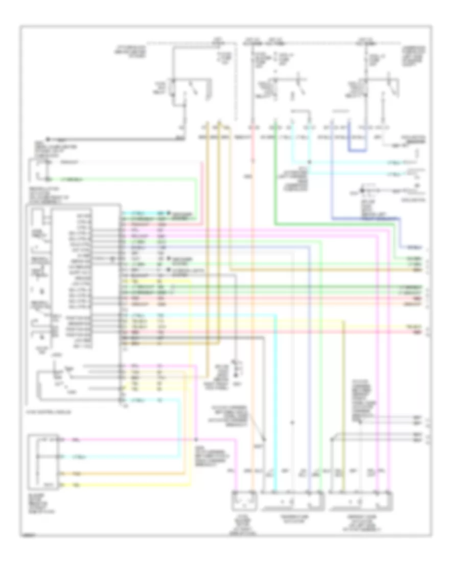
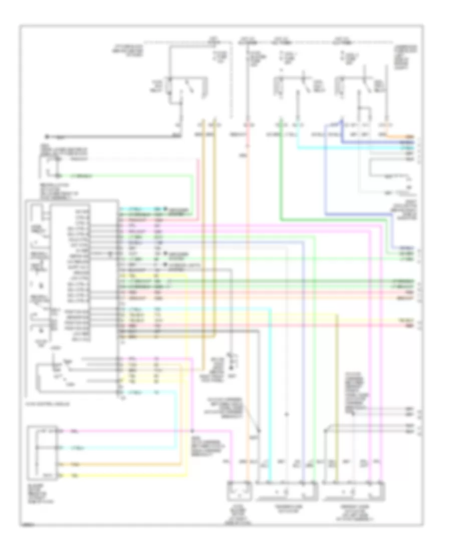
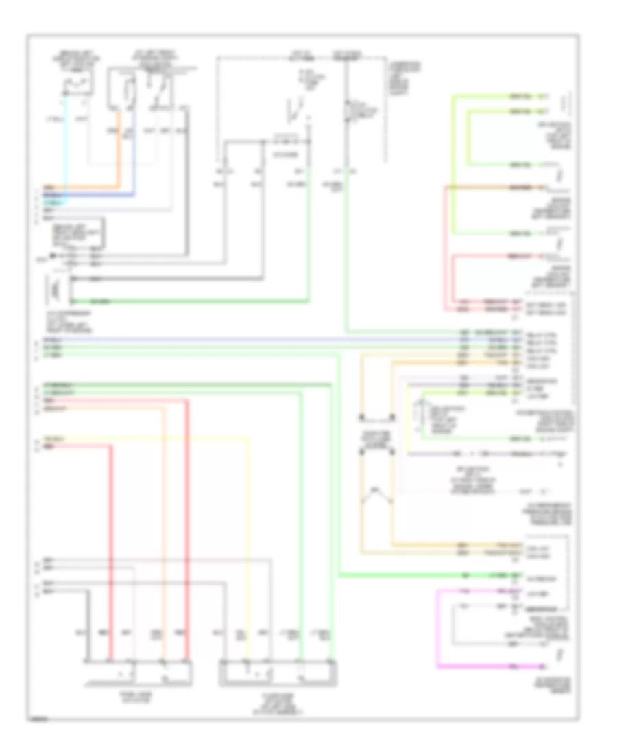
2.4L VIN Z, Manual A/C Wiring Diagram (1 of 2) for Saturn Vue Red Line 2007
 https://portal-diagnostov.com/license.html
Automotive Electricians Portal FZCO
Automotive Electricians Portal FZCO
https://portal-diagnostov.com/license.html
https://portal-diagnostov.com/license.html
Automotive Electricians Portal FZCO
Automotive Electricians Portal FZCOList of elements for 2.4L VIN Z, Manual A/C Wiring Diagram (1 of 2) for Saturn Vue Red Line 2007:
- (in hvac harness, between c202 & panel mode actuator harness breakout)
- (in hvac harness, between defrost mode & panel mode actuator harness breakout) s206
- 5v ref
- A/c on ind
- A/c req sig
- A/c sw sig
- A10 c1
- B c5
- B11
- B11 c3
- Blower motor resistor (at right side of hvac)
- C2 c1
- Cold ctrl
- Cool fan hi relay
- Cool fan low relay
- Cool hi fuse 40a
- Cool lo fuse 20a
- Cooling fan
- Cooling fan resistor
- Ctrl a
- Ctrl b
- D2 c2
- Defog ind
- Defogger system
- Defrost mode actuator (on left side of hvac assembly)
- F12 c2
- G101
- G201
- G203 (near lower center of dash, on i/p fuse block)
- Ground
- High
- Hot at all times
- Hot ctrl
- Hot in run
- Hvac blo relay
- Hvac blower fuse 40a
- Hvac blower motor (at right side of hvac)
- Hvac control module
- Hvac fuse 10a
- I/p fuse block (behind center of dash)
- Ign 1 vol
- Ign 3 vol
- Interior lights system
- Logic
- Low ctrl
- Low ref
- Mode switch
- Off
- Position sig
- Recircu- lation ind
- Recircu- lation sw
- Recirculation actuator (on lower front of hvac assembly)
- Red
- S111 (in forward light harness, near underhood fuse block)
- S205 (in i/p harness, between hvac & radio harness breakout)
- S207
- Sensor sig
- Sol ctrl a
- Sol ctrl b
- Splice pack sp101 (behind left front headlight)
- Splice pack sp201 (behind right front kick panel)
- Supp volt
- Sw sig
- Tan
- Temp ctrl
- Temperature actuator
- Underhood fuse block (left side of engine compt)
2.4L VIN Z, Manual A/C Wiring Diagram (2 of 2) for Saturn Vue Red Line 2007
 https://portal-diagnostov.com/license.html
Automotive Electricians Portal FZCO
Automotive Electricians Portal FZCO
https://portal-diagnostov.com/license.html
https://portal-diagnostov.com/license.html
Automotive Electricians Portal FZCO
Automotive Electricians Portal FZCOList of elements for 2.4L VIN Z, Manual A/C Wiring Diagram (2 of 2) for Saturn Vue Red Line 2007:
- 5v ref
- A/c clutch fuse 10a
- A/c clutch relay
- A/c compressor clutch (at lower left front of engine)
- A/c diode
- A/c refrigerant pressure sensor (in a/c high side pressure line)
- A/c req sig
- A11
- A12
- A6 c1
- B12
- Body control module (bcm) (below front of center floor console)
- Bus +
- Bus -
- Can high
- Can low
- Computer data lines system
- E10
- E11
- Ect sig
- Engine control module (ecm) (left rear of engine compt)
- Engine coolant temperature (ect) sensor
- Evaporator temperature sensor
- Floor mode actuator (on left side of hvac assembly)
- G101
- Hot at all times
- Hot in run or start
- Ig 3 vol
- Low ref
- Panel mode actuator
- Red
- Relay ctrl
- Sensor sig
- Splice pack sp101 (behind left front headlight)
- Tan
- Underhood fuse block (left side of engine compt)
3.5L VIN 4
3.5L VIN 4, Compressor Wiring Diagram for Saturn Vue Red Line 2007
 https://portal-diagnostov.com/license.html
Automotive Electricians Portal FZCO
Automotive Electricians Portal FZCO
https://portal-diagnostov.com/license.html
https://portal-diagnostov.com/license.html
Automotive Electricians Portal FZCO
Automotive Electricians Portal FZCOList of elements for 3.5L VIN 4, Compressor Wiring Diagram for Saturn Vue Red Line 2007:
- (at right side
- (top left front of engine)
- 5v reference
- A/c clutch fuse 10a
- A/c clutch relay
- A/c compressor clutch (at lower left front of engine)
- A/c diode
- A/c press sens
- A/c refrigerant pressure sensor (in a/c high side pressure line)
- A/c req sig
- A/c request
- A/t
- A12
- A6 c1
- A6 c2
- B12
- Body control module (bcm) (below front of center floor console)
- Bus +
- Bus -
- C11
- Can high
- Can low
- Clu rly ctrl
- Computer data lines system
- E11
- Evap temp sens
- Evaporator temperature sensor
- G101
- Hot at all times
- Hot in run or start
- Hvac control module
- Logic
- Low ref
- Low reference
- Of engine, under intake air duct)
- Powertrain control module (pcm) (right side of engine compt)
- Splice pack sp 115
- Splice pack sp101 (behind left front headlight)
- Splice pack sp114
- Tan
- Underhood fuse block (left side of engine compt)
3.5L VIN 4, Manual A/C Wiring Diagram (1 of 2) for Saturn Vue Red Line 2007
 https://portal-diagnostov.com/license.html
Automotive Electricians Portal FZCO
Automotive Electricians Portal FZCO
https://portal-diagnostov.com/license.html
https://portal-diagnostov.com/license.html
Automotive Electricians Portal FZCO
Automotive Electricians Portal FZCOList of elements for 3.5L VIN 4, Manual A/C Wiring Diagram (1 of 2) for Saturn Vue Red Line 2007:
- (in hvac harness, between c202 & panel mode actuator harness breakout)
- (in hvac harness, between defrost mode & panel mode actuator harness breakout) s206
- 5v ref
- A/c on ind
- A/c req sig
- A/c sw sig
- A11
- A12
- A2 c1
- B c5
- B11
- Blower motor (at right side of hvac)
- Blower motor resistor (at right side of hvac)
- C10 c1
- Cold ctrl
- Cool 1 fuse 25a
- Cool 2 fuse 25a
- Cool fan 1 relay
- Cool fan 2 relay
- Ctrl a
- Ctrl b
- D9 c3
- Defog ind
- Defogger system
- Defrost mode actuator (on left side of hvac assembly)
- F2 c3
- G201
- G203 (near lower center of dash, on i/p fuse block)
- Ground
- High
- Hot at all times
- Hot ctrl
- Hot in run
- Hvac
- Hvac blo relay
- Hvac blower fuse 40a
- Hvac control module
- Hvac fuse 10a
- I/p fuse block (behind center of dash)
- Ign 3 vol
- Interior lights system
- Logic
- Low ctrl
- Low ref
- Mode switch
- Off
- Position sig
- Recircu- lation ind
- Recircu- lation sw
- Recirculation actuator (on lower front of hvac assembly)
- Red
- Right cooling fan (behind right side of radiator)
- S205 (in i/p harness, between hvac & radio harness breakout)
- S207
- Sensor sig
- Sol ctrl a
- Sol ctrl b
- Splice pack sp201 (behind right front kick panel)
- Supp volt
- Sw sig
- Tan
- Temp ctrl
- Temperature actuator
- Underhood fuse block (left side of engine compt)
3.5L VIN 4, Manual A/C Wiring Diagram (2 of 2) for Saturn Vue Red Line 2007
 https://portal-diagnostov.com/license.html
Automotive Electricians Portal FZCO
Automotive Electricians Portal FZCO
https://portal-diagnostov.com/license.html
https://portal-diagnostov.com/license.html
Automotive Electricians Portal FZCO
Automotive Electricians Portal FZCOList of elements for 3.5L VIN 4, Manual A/C Wiring Diagram (2 of 2) for Saturn Vue Red Line 2007:
- (at left front of engine compt) cooling fan relay 3
- (behind left front headlight) splice pack sp101
- (behind left side of radiator) left cooling fan
- 5v ref
- 87a
- A/c clutch fuse 10a
- A/c clutch relay
- A/c compressor clutch (at lower left front of engine)
- A/c diode
- A/c refrigerant pressure sensor (in a/c high side pressure line)
- A/c req sig
- A/t
- A12
- A6 c1
- B12
- Body control module (bcm) (below front of center floor console)
- C11
- Can high
- Can low
- Computer data lines system
- E11
- Ect sens 1 sig
- Ect sens 2 sig
- Engine coolant temperature (ect) sensor 1
- Engine coolant temperature (ect) sensor 2
- Evaporator temperature sensor
- Floor mode actuator (on left side of hvac assembly)
- G101
- Hot at all times
- Hot in run or start
- Low ref
- Panel mode actuator
- Powertrain control module (pcm) (right side of engine compt)
- Red
- Relay ctrl
- Sensor sig
- Splice pack sp114 (at right side of engine, under intake air duct)
- Splice pack sp115 (top left front of engine)
- Tan
- Underhood fuse block (left side of engine compt)
ANTI-LOCK BRAKES
Anti-lock Brakes Wiring Diagram (1 of 2) for Saturn Vue Red Line 2007
 https://portal-diagnostov.com/license.html
Automotive Electricians Portal FZCO
Automotive Electricians Portal FZCO
https://portal-diagnostov.com/license.html
https://portal-diagnostov.com/license.html
Automotive Electricians Portal FZCO
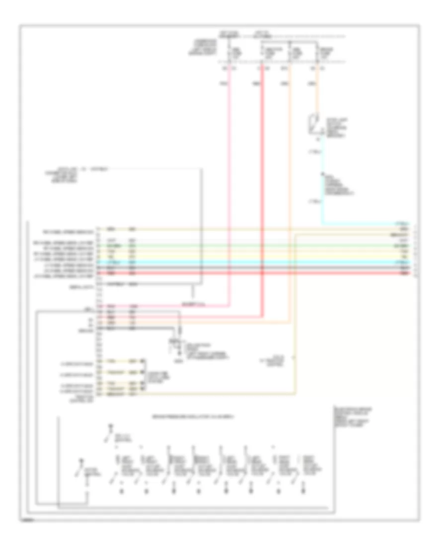
Automotive Electricians Portal FZCOList of elements for Anti-lock Brakes Wiring Diagram (1 of 2) for Saturn Vue Red Line 2007:
- 2.2l & w/ traction control
- Abs fuse 10a
- Abs fuse 20a
- Abs pwr fuse 40a
- B12
- Brake fuse 10a
- Brake pressure modulator valve (bpmv)
- Computer data lines system
- Data link connector (dlc) (lower left side of dash)
- Electronic brake control module (ebcm) (near left front shock tower)
- Except 2.4l
- G205
- Ground
- Hi spd data bus+
- Hi spd data bus-
- Hot at all times
- Hot in on or start
- Ign 1
- Left front inlet solenoid valve
- Left front outlet solenoid valve
- Left rear inlet solenoid valve
- Left rear outlet solenoid valve
- Lf wheel speed sens low ref
- Lf wheel speed sens sig
- Lr wheel speed sens low ref
- Lr wheel speed sens sig
- Motor control
- Pnk
- Red
- Rf wheel speed sens low ref
- Rf wheel speed sens sig
- Right front inlet solenoid valve
- Right front outlet solenoid valve
- Right rear inlet solenoid valve
- Right rear outlet solenoid valve
- Rr wheel speed sens low ref
- Rr wheel speed sens sig
- S304 (in body harness, near cross car breakout)
- Serial data
- Sol vlv control
- Splice pack sp205 (left front corner of passenger compt)
- Stop lamp switch (on brake pedal bracket)
- Tan
- Traction control sw
- Underhood fuse block (left side of engine compt)
Anti-lock Brakes Wiring Diagram (2 of 2) for Saturn Vue Red Line 2007
 https://portal-diagnostov.com/license.html
Automotive Electricians Portal FZCO
Automotive Electricians Portal FZCO
https://portal-diagnostov.com/license.html
https://portal-diagnostov.com/license.html
Automotive Electricians Portal FZCO
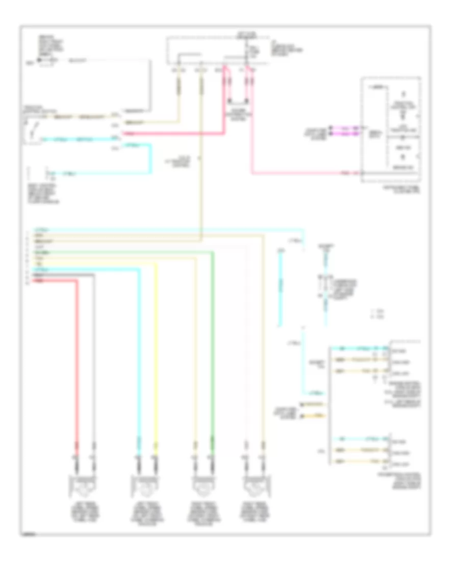
Automotive Electricians Portal FZCOList of elements for Anti-lock Brakes Wiring Diagram (2 of 2) for Saturn Vue Red Line 2007:
- (2.4l: left rear of engine compt)
- (behind right front kick panel) splice pack sp201
- (or pnk)
- 2.2l
- 2.2l & w/ traction control
- 2.4l
- 3.5l
- Abs ind
- Body control module (bcm) (below front of center floor console)
- Brake ind
- C1 c4
- C2 c5
- Can high
- Can low
- Computer data lines system
- E12
- Engine control module (ecm) (2.2l: right side of engine compt)
- Except 3.5l
- G201
- Hot in on or start
- I/p fuse block (behind center of dash)
- Ign 1 fuse 10a
- Instrument panel cluster (ipc)
- Left front wheel speed sensor (wss) (on left front wheel steering knuckle)
- Left rear wheel speed sensor (wss) (on left rear wheel hub)
- Logic
- Low traction ind
- Nca
- Pnk
- Power distribution system
- Powertrain control module (pcm) (right side of engine compt)
- Red
- Right front wheel speed sensor (wss) (on right front wheel steering knuckle)
- Right rear wheel speed sensor (wss) (on right rear wheel hub)
- Serial data
- Sw sig
- Tan
- Traction control off ind
- Traction control switch
- Underhood fuse block (left side of engine compt)
ANTI-THEFT
Anti-theft Wiring Diagram for Saturn Vue Red Line 2007
 https://portal-diagnostov.com/license.html
Automotive Electricians Portal FZCO
Automotive Electricians Portal FZCO
https://portal-diagnostov.com/license.html
https://portal-diagnostov.com/license.html
Automotive Electricians Portal FZCO
Automotive Electricians Portal FZCOList of elements for Anti-theft Wiring Diagram for Saturn Vue Red Line 2007:
- (behind center of dash) i/p fuse block
- (behind left front headlight) sp101
- 12v ref
- A12
- B12
- Bcm/ cluster fuse 10a
- Body control module (bcm) (below front of center floor console)
- C10
- C12
- Closed sig
- Computer data lines system
- D10
- Data
- Data bus+
- Data bus-
- Door lock ctrl
- Door unlock ctrl
- Dr lck fuse 20a
- Dr lock relay
- Driver door latch (inside rear of left front door)
- Driver door lock switch
- Driver unlock rly ctrl
- Drv dr unlock relay
- E10
- E12
- F10
- F12
- Front passenger door latch (inside rear of right front door)
- Front passenger door lock switch
- G101
- G301
- Hood ajar switch (integral to hood latch assembly)
- Horn relay ctrl
- Horns system
- Hot at all times
- Ind
- Instrument panel cluster (ipc)
- Int lts fuse 10a
- Interior lights system
- Left rear door latch (inside rear of left rear door)
- Lf dr ajar sw sig
- Liftgate ajar sw sig
- Liftgate latch
- Lock
- Lock/ mirror fuse 10a
- Low ref
- Nca
- Pass dr
- Pass dr ajar sw sig
- Passlock sensor (at top of steering column)
- Power
- Power distribution system
- Return
- Right rear door latch (inside rear of right rear door)
- S400
- Security
- Security ind ctrl
- Sensor signal
- Sp301 (under left front seat)
- Starter generator control module (sgcm) (left front of engine compt)
- Sw lock sig
- Sw sig
- Tan
- Unlock
- Unlock relay
- Unlock sig
- Vbatt
BODY CONTROL MODULES
Body Control Modules Wiring Diagram for Saturn Vue Red Line 2007
 https://portal-diagnostov.com/license.html
Automotive Electricians Portal FZCO
Automotive Electricians Portal FZCO
https://portal-diagnostov.com/license.html
https://portal-diagnostov.com/license.html
Automotive Electricians Portal FZCO
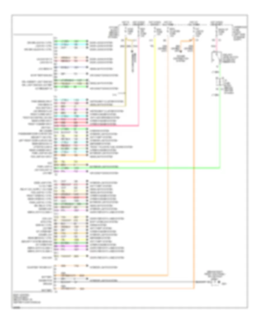
Automotive Electricians Portal FZCOList of elements for Body Control Modules Wiring Diagram for Saturn Vue Red Line 2007:
- (behind right front kick panel) splice pack sp201
- 12 volt ref
- 2.4l
- A/c request in
- A10
- A11
- A12
- Acc
- Air conditioning system
- Anti-lock brakes system
- Anti-theft system
- B10
- B11
- B12
- Back up fuse 10a
- Battery
- Bcm fuse 10a
- Bcm ign fuse 10a
- Bcm/ cluster fuse 10a
- Body control module (bcm) (below front of center floor console)
- Btsi ctrl
- C11
- Can high
- Can low
- Computer data lines system
- Coolant level switch (in coolant reservoir)
- Courtesy power out
- Defogger system
- Dimmer high
- Dimmer low
- Dimmer pwr
- Dome lamp ctrl
- Door locks system
- Driver lock rly ctrl
- Driver unlock rly ctrl
- Drl ambient light sns sig
- Drl light sns sig low ref
- Drl relay ctrl
- Evap temp sns sig
- Exterior lights system
- F9 c3
- Fog lamp rly ctrl
- Fog lamp sw input
- Front washer input
- Front wiper input
- Front wiper rly ctrl
- G201
- Ground
- Headlights system
- High beam in
- Horn rly ctrl
- Horns system
- Hot at all times
- Hot in run
- Hot in run or acc
- Hot in run or start
- Hvac fuse 10a
- I/p fuse block (behind center of dash)
- Ignition 1
- Instrument cluster system
- Int lights fuse 10a
- Int wiper pwr
- Int wiper ret
- Interior lights system
- Key minder
- Left front door ajar sw sig
- Liftgate ajar in
- Lock rly ctrl
- Lock sw in
- Low beam in
- Low brake fluid
- Low coolant in
- Low ref
- Park brake input
- Park lamp in
- Park lamp rly ctrl
- Park lamp sw sig
- Passenger door ajar sw sig
- Pnk
- Power distribution system
- Rear defog rly ctrl
- Rear defog sw in
- Rear washer input
- Rear wiper input
- Rear wiper rly ctrl
- Red
- Run ignition 3
- Security ind ctrl
- Security system sens sig
- Serial data (class ii)
- Shift interlock system
- Tan
- Traction control sw sig
- Trunk, tailgate, fuel doors system
- Underhood fuse block (left side of engine compt)
- Unlock sw in
- Warning system
- Wiper/washer system
COMPUTER DATA LINES
2.2L VIN D
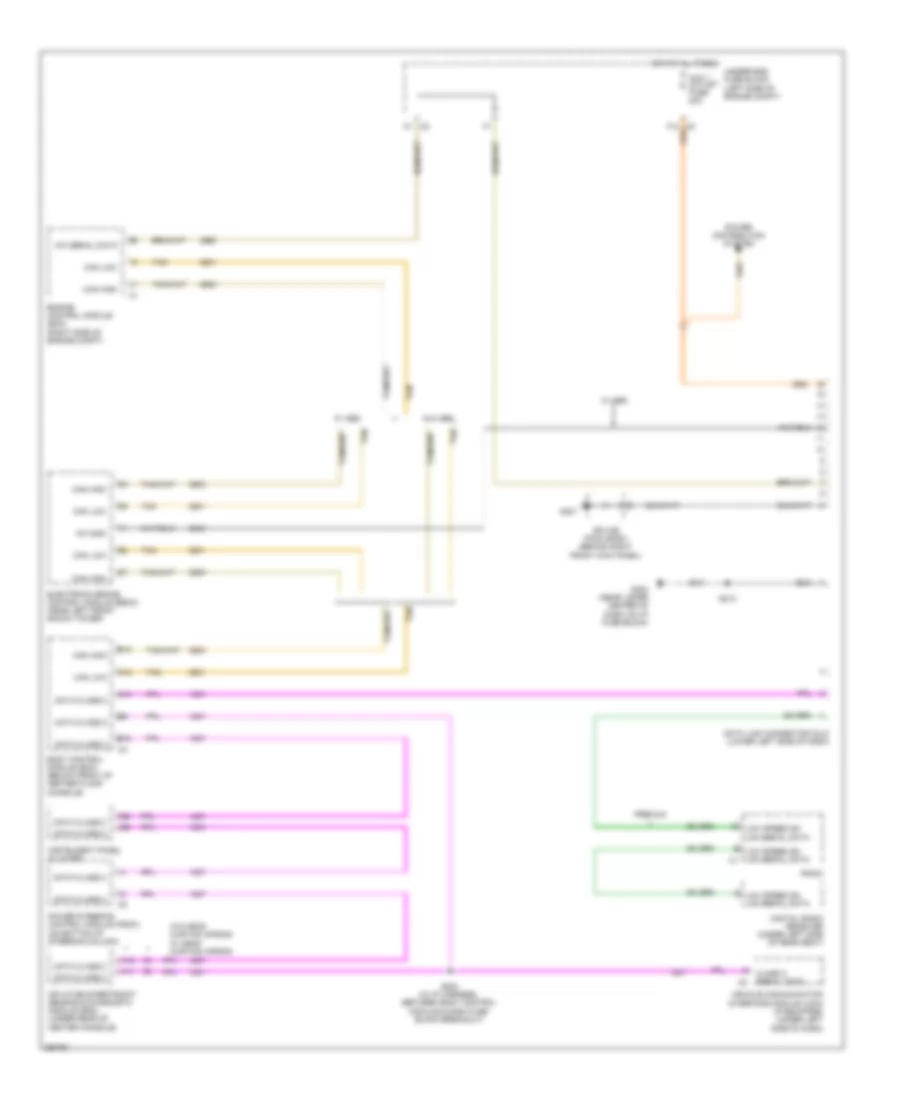
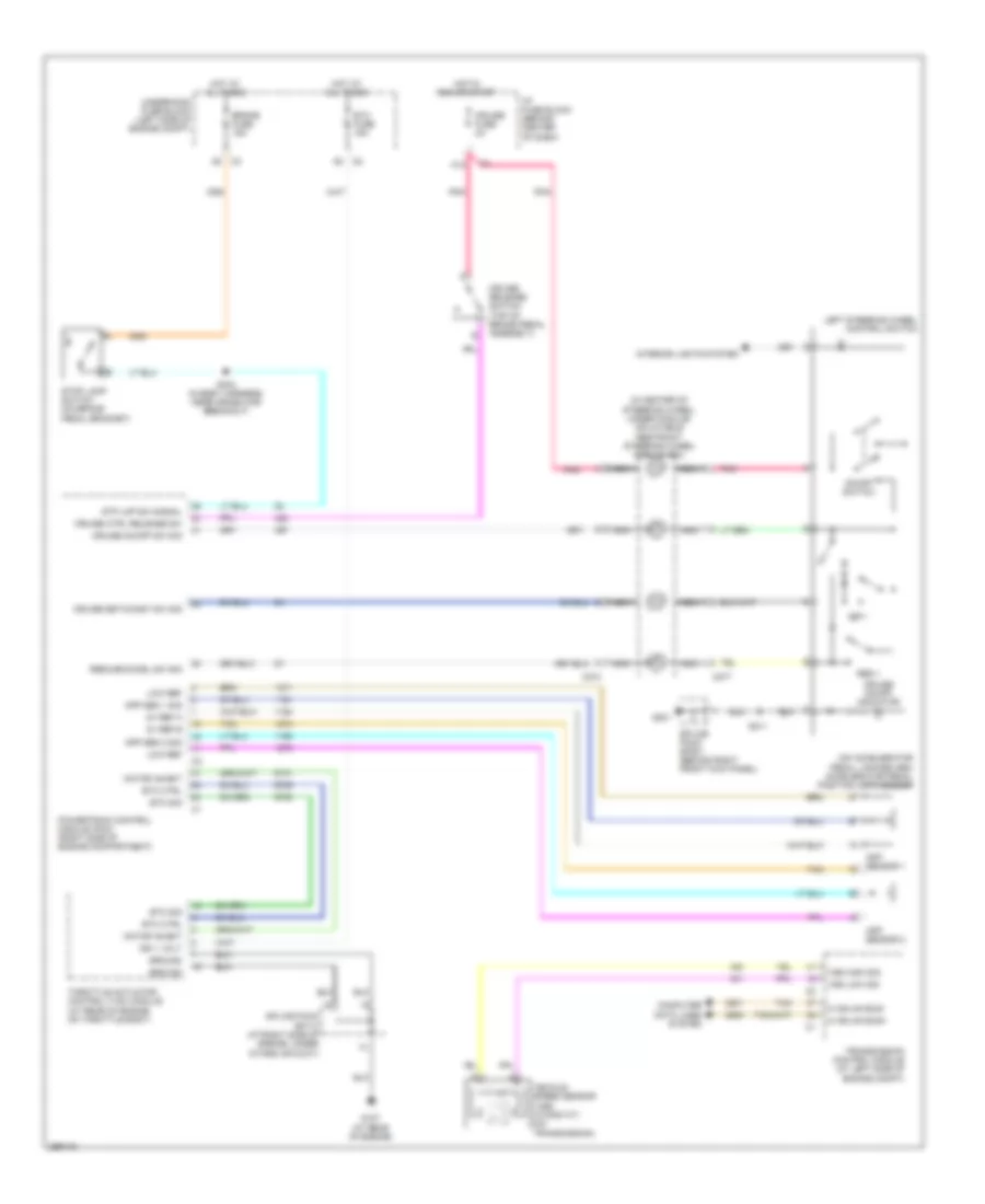
2.2L VIN D, Computer Data Lines Wiring Diagram, A/T for Saturn Vue Red Line 2007
 https://portal-diagnostov.com/license.html
Automotive Electricians Portal FZCO
Automotive Electricians Portal FZCO
https://portal-diagnostov.com/license.html
https://portal-diagnostov.com/license.html
Automotive Electricians Portal FZCO
Automotive Electricians Portal FZCOList of elements for 2.2L VIN D, Computer Data Lines Wiring Diagram, A/T for Saturn Vue Red Line 2007:
- (2.2l)
- (2.2l) s314
- (2.2l) s315
- (3.5l)
- 2.2l
- 2.2l w/o abs
- 3.5l
- A10
- A11
- A12
- Aux 1 outlet fuse 20a
- B10
- B12
- Body control module (bcm) (below front of center floor console)
- Can high
- Can low
- Class 2 serial data
- Data class 2
- Data link connector (dlc) (lower left side of dash)
- Digital radio receiver (under left side of rear seat)
- Electronic brake control module (ebcm) (near left front shock tower)
- Engine control module (ecm) powertrain control module (pcm) (right side of engine compt)
- F12
- G201
- G203 (near lower center of dash, on i/p fuse block)
- Hot at all times
- Inflatable restraint sensing & diagnostic module (sdm) (under rear of center console)
- Instrument panel cluster
- Kw 2000
- Low speed gm lan serial data
- Power distribution system
- Power steering control module (pscm) (on bottom of steering column)
- Radio
- S203 (in i/p harness, between body control module & dash fuse block breakout)
- S213
- Splice pack sp201 (behind right front kick panel)
- Tan
- Transmission control module (tcm) (2.2l) (at left side of engine compt)
- Underhood fuse block (left side of engine compt)
- Vehicle communication interface module (vcim) (if equipped) (under left side of dash)
- W/ abs
- W/ premium
- W/o head curtain air bag 3.5l, w/ head curtain air bag
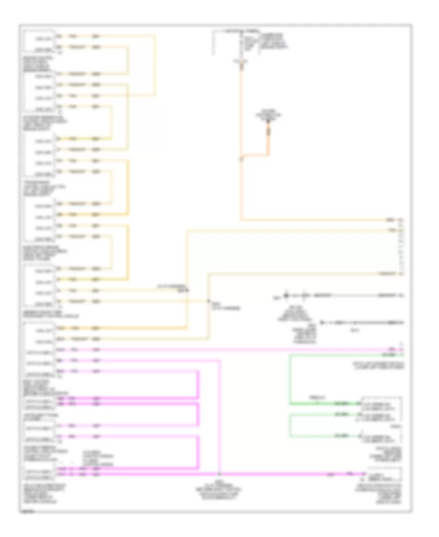
2.2L VIN D, Computer Data Lines Wiring Diagram, M/T for Saturn Vue Red Line 2007
 https://portal-diagnostov.com/license.html
Automotive Electricians Portal FZCO
Automotive Electricians Portal FZCO
https://portal-diagnostov.com/license.html
https://portal-diagnostov.com/license.html
Automotive Electricians Portal FZCO
Automotive Electricians Portal FZCOList of elements for 2.2L VIN D, Computer Data Lines Wiring Diagram, M/T for Saturn Vue Red Line 2007:
- A10
- A11
- A12
- Aux 1 outlet fuse 20a
- B10
- B12
- Body control module (bcm) (below front of center floor console)
- C2 a1
- C3 f12
- Can high
- Can low
- Class 2 serial data
- Data class 2
- Data link connector (dlc) (lower left side of dash)
- Digital radio receiver (under left side of rear seat)
- Electronic brake control module (ebcm) (near left front shock tower)
- Engine control module (ecm) (right side of engine compt)
- G201
- G203 (near lower center of dash, on i/p fuse block)
- Hot at all times
- Inflatable restraint sensing & diagnostic module (sdm) (under rear of center console)
- Instrument panel cluster
- Kw 2000
- Kw serial data
- Low speed gm lan serial data
- Low speed gm lan serial data c1
- Power distribution system
- Power steering control module (pscm) (on bottom of steering column)
- Premium
- Radio
- S203 (in i/p harness, between body control module & dash fuse block breakout)
- S213
- Splice pack sp201 (behind right front kick panel)
- Tan
- Underhood fuse block (left side of engine compt)
- Vehicle communication interface module (vcim) (if equipped) (under left side of dash)
- W/ abs
- W/o abs
- W/o head curtain air bag w/ head curtain air bag
2.4L VIN Z
2.4L VIN Z, Computer Data Lines Wiring Diagram for Saturn Vue Red Line 2007
 https://portal-diagnostov.com/license.html
Automotive Electricians Portal FZCO
Automotive Electricians Portal FZCO
https://portal-diagnostov.com/license.html
https://portal-diagnostov.com/license.html
Automotive Electricians Portal FZCO
Automotive Electricians Portal FZCOList of elements for 2.4L VIN Z, Computer Data Lines Wiring Diagram for Saturn Vue Red Line 2007:
- (in i/p harness) s201
- A10
- A11
- A12
- Aux 1 outlet fuse 20a
- B10
- B12
- Body control module (bcm) (below front of center floor console)
- Can high
- Can low
- Class 2 serial data
- Data class 2
- Data link connector (dlc) (lower left side of dash)
- Digital radio receiver (under left side of rear seat)
- Electronic brake control module (ebcm) (near left front shock tower)
- Engine control module (ecm) (right side of engine compt)
- F12 c3
- G201
- G203 (near lower center of dash, on i/p fuse block)
- Generator battery disconnect control module
- Hot at all times
- Inflatable restraint sensing & diagnostic module (sdm) (under rear of center console)
- Instrument panel cluster
- Low speed gm lan serial data
- Low speed gm lan serial data c1
- Power distribution system
- Power steering control module (pscm) (on bottom of steering column)
- Premium
- Radio
- S200 (in i/p harness)
- S203 (in i/p harness, between body control module & dash fuse block breakout)
- S213
- Splice pack sp201 (behind right front kick panel)
- Starter generator control module (sgcm) (left front of engine compt)
- Tan
- Transmission control module (tcm) (at left side of engine compt)
- Underhood fuse block (left side of engine compt)
- Vehicle communication interface module (vcim) (if equipped) (under left side of dash)
- W/o head curtain air bag w/ head curtain air bag
3.5L VIN 4
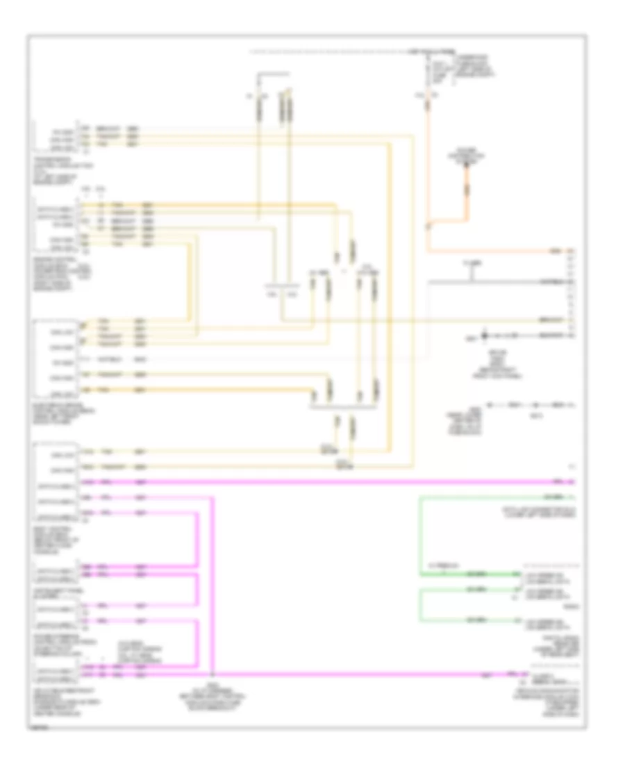
3.5L VIN 4, Computer Data Lines Wiring Diagram, A/T for Saturn Vue Red Line 2007
 https://portal-diagnostov.com/license.html
Automotive Electricians Portal FZCO
Automotive Electricians Portal FZCO
https://portal-diagnostov.com/license.html
https://portal-diagnostov.com/license.html
Automotive Electricians Portal FZCO
Automotive Electricians Portal FZCOList of elements for 3.5L VIN 4, Computer Data Lines Wiring Diagram, A/T for Saturn Vue Red Line 2007:
- (2.2l)
- (2.2l) s314
- (2.2l) s315
- (3.5l)
- 2.2l
- 2.2l w/o abs
- 3.5l
- A10
- A11
- A12
- Aux 1 outlet fuse 20a
- B10
- B12
- Body control module (bcm) (below front of center floor console)
- Can high
- Can low
- Class 2 serial data
- Data class 2
- Data link connector (dlc) (lower left side of dash)
- Digital radio receiver (under left side of rear seat)
- Electronic brake control module (ebcm) (near left front shock tower)
- Engine control module (ecm) powertrain control module (pcm) (right side of engine compt)
- F12
- G201
- G203 (near lower center of dash, on i/p fuse block)
- Hot at all times
- Inflatable restraint sensing & diagnostic module (sdm) (under rear of center console)
- Instrument panel cluster
- Kw 2000
- Low speed gm lan serial data
- Power distribution system
- Power steering control module (pscm) (on bottom of steering column)
- Radio
- S203 (in i/p harness, between body control module & dash fuse block breakout)
- S213
- Splice pack sp201 (behind right front kick panel)
- Tan
- Transmission control module (tcm) (2.2l) (at left side of engine compt)
- Underhood fuse block (left side of engine compt)
- Vehicle communication interface module (vcim) (if equipped) (under left side of dash)
- W/ abs
- W/ premium
- W/o head curtain air bag 3.5l, w/ head curtain air bag
COOLING FAN
2.2L VIN D
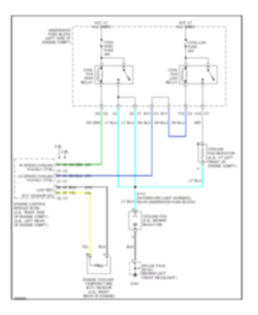
2.2L VIN D, Cooling Fan Wiring Diagram for Saturn Vue Red Line 2007
 https://portal-diagnostov.com/license.html
Automotive Electricians Portal FZCO
Automotive Electricians Portal FZCO
https://portal-diagnostov.com/license.html
https://portal-diagnostov.com/license.html
Automotive Electricians Portal FZCO
Automotive Electricians Portal FZCOList of elements for 2.2L VIN D, Cooling Fan Wiring Diagram for Saturn Vue Red Line 2007:
- 2.2l
- 2.4l
- A10 c1
- B11
- B11 c3
- C2 c1
- Cool fan high relay
- Cool fan low relay
- Cool high fuse 40a
- Cool low fuse 20a
- Cooling fan (2.2l: behind radiator)
- Cooling fan resistor (2.2l: at left front of engine compt)
- D2 c2
- Ect sensor sig
- Engine control module (ecm) (2.2l: right side of engine compt) (2.4l: left rear of engine compt)
- Engine coolant temperature (ect) sensor (2.2l: right rear of engine)
- F12 c2
- G101
- Hi speed cooling fan rly ctrl c1
- Hot at all times
- Lo speed cooling fan rly ctrl c1
- Low ref
- Splice pack sp101 (behind left front headlight)
- Underhood fuse block (left side of engine compt)
2.4L VIN Z
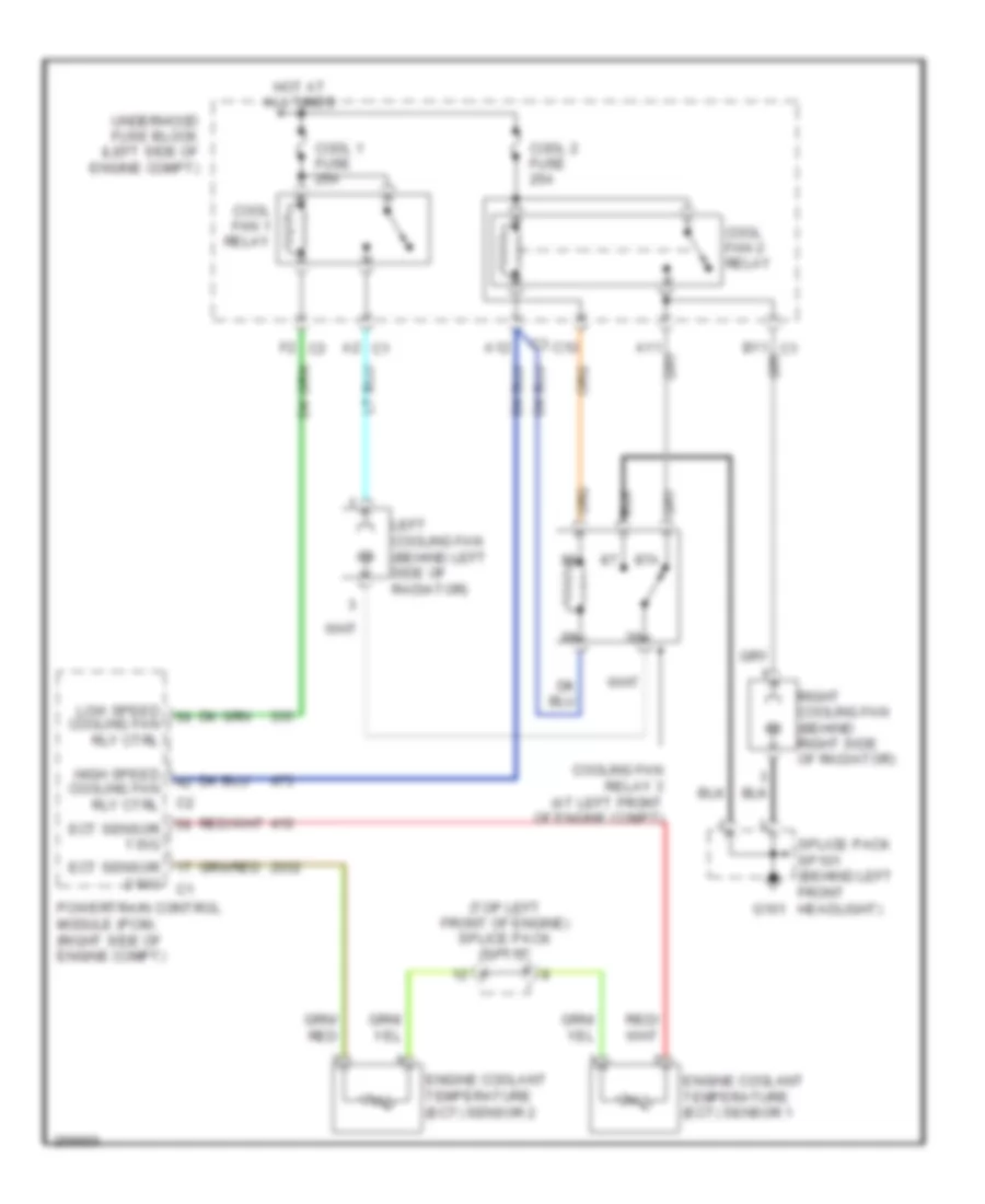
2.4L VIN Z, Cooling Fan Wiring Diagram, Except Hybrid for Saturn Vue Red Line 2007
 https://portal-diagnostov.com/license.html
Automotive Electricians Portal FZCO
Automotive Electricians Portal FZCO
https://portal-diagnostov.com/license.html
https://portal-diagnostov.com/license.html
Automotive Electricians Portal FZCO
Automotive Electricians Portal FZCOList of elements for 2.4L VIN Z, Cooling Fan Wiring Diagram, Except Hybrid for Saturn Vue Red Line 2007:
- 2.2l
- 2.4l
- A10 c1
- B11
- B11 c3
- C2 c1
- Cool fan high relay
- Cool fan low relay
- Cool high fuse 40a
- Cool low fuse 20a
- Cooling fan (2.2l: behind radiator)
- Cooling fan resistor (2.2l: at left front of engine compt)
- D2 c2
- Ect sensor sig
- Engine control module (ecm) (2.2l: right side of engine compt) (2.4l: left rear of engine compt)
- Engine coolant temperature (ect) sensor (2.2l: right rear of engine)
- F12 c2
- G101
- Hi speed cooling fan rly ctrl c1
- Hot at all times
- Lo speed cooling fan rly ctrl c1
- Low ref
- Splice pack sp101 (behind left front headlight)
- Underhood fuse block (left side of engine compt)
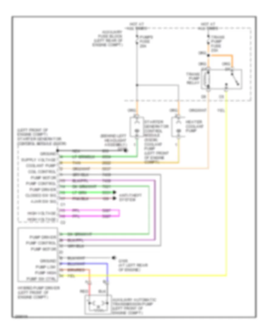
2.4L VIN Z, Cooling Fan Wiring Diagram, Hybrid for Saturn Vue Red Line 2007
 https://portal-diagnostov.com/license.html
Automotive Electricians Portal FZCO
Automotive Electricians Portal FZCO
https://portal-diagnostov.com/license.html
https://portal-diagnostov.com/license.html
Automotive Electricians Portal FZCO
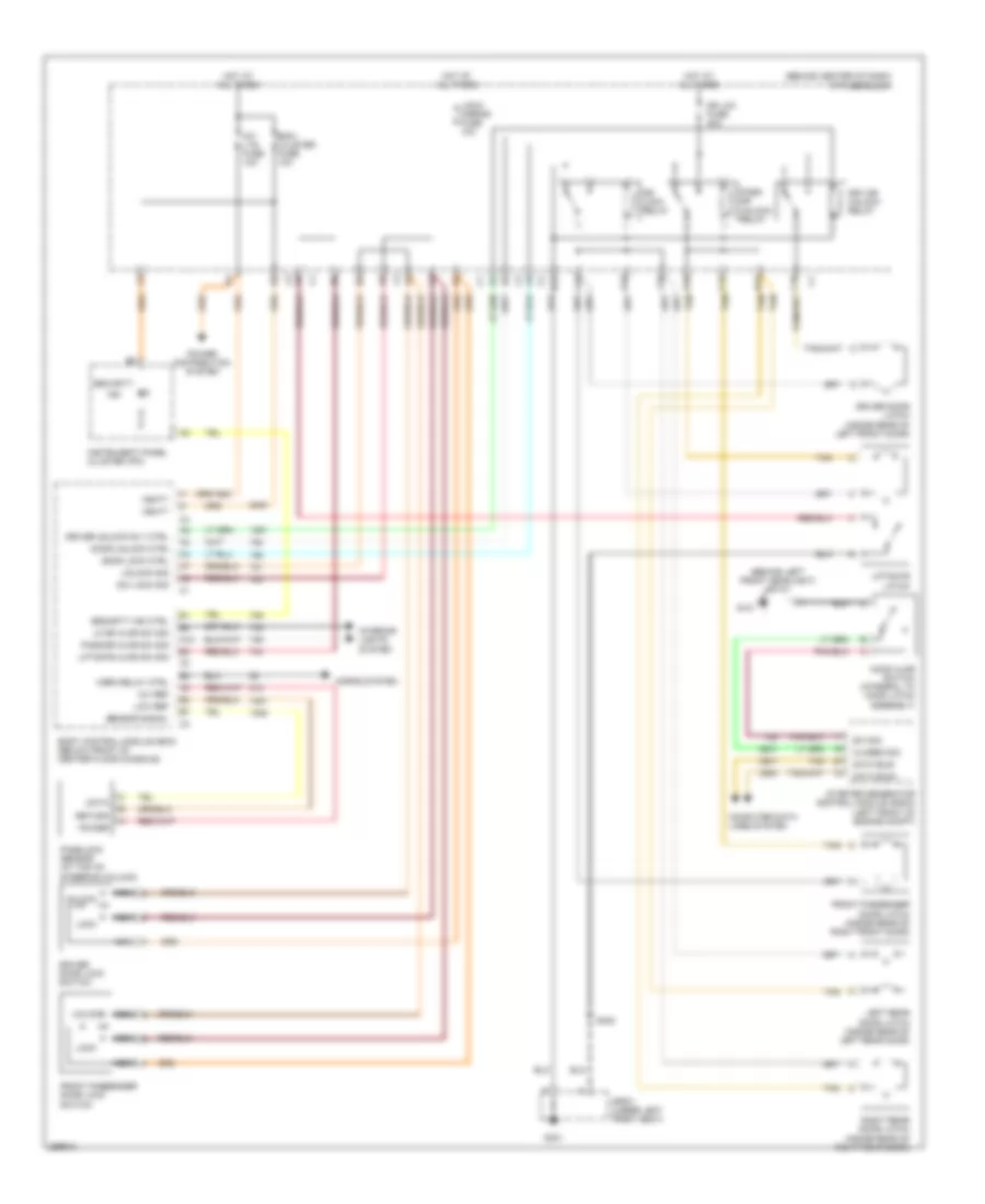
Automotive Electricians Portal FZCOList of elements for 2.4L VIN Z, Cooling Fan Wiring Diagram, Hybrid for Saturn Vue Red Line 2007:
- (behind left headlight assembly) g108
- (left front of engine compt) starter generator control module (sgcm)
- Ajar sw sig
- Anti-theft system
- Auxiliary automatic transmission pump (left front of engine compt)
- Auxiliary fuse block (left rear of engine compt)
- Closed sw sig
- Coil control
- Coolant pump
- G105 (at left rear of engine)
- Ground
- Heater coolant pump
- High voltage
- Hot at all times
- Hybrid pump driver (left front of engine compt)
- Nca
- Pump control
- Pump driver
- Pump high
- Pump low
- Pump motor
- Pump sw ctrl
- Pumps fuse 20a
- Red
- Starter generator control module (sgcm) coolant pump (left front of engine compt)
- Tan
- Trans pump fuse 20a
- Trans pump relay
3.5L VIN 4
3.5L VIN 4, Cooling Fan Wiring Diagram for Saturn Vue Red Line 2007
 https://portal-diagnostov.com/license.html
Automotive Electricians Portal FZCO
Automotive Electricians Portal FZCO
https://portal-diagnostov.com/license.html
https://portal-diagnostov.com/license.html
Automotive Electricians Portal FZCO
Automotive Electricians Portal FZCOList of elements for 3.5L VIN 4, Cooling Fan Wiring Diagram for Saturn Vue Red Line 2007:
- (top left front of engine) splice pack sp115
- 87a
- A12
- A2 c1
- C10
- Cool 1 fuse 25a
- Cool 2 fuse 25a
- Cool fan 1 relay
- Cool fan 2 relay
- Cooling fan relay 3 (at left front of engine compt)
- Ect sensor 1 sig
- Ect sensor 2 sig
- Engine coolant temperature (ect) sensor 1
- Engine coolant temperature (ect) sensor 2
- F2 c3
- High speed cooling fan rly ctrl
- Hot at all times
- Left cooling fan (behind left side of radiator)
- Low speed cooling fan rly ctrl
- Powertrain control module (pcm) (right side of engine compt)
- Right cooling fan (behind right side of radiator)
- Splice pack sp101 (behind left front headlight) g101
- Underhood fuse block (left side of engine compt)
CRUISE CONTROL
2.2L VIN D
2.2L VIN D, Cruise Control Wiring Diagram for Saturn Vue Red Line 2007
 https://portal-diagnostov.com/license.html
Automotive Electricians Portal FZCO
Automotive Electricians Portal FZCO
https://portal-diagnostov.com/license.html
https://portal-diagnostov.com/license.html
Automotive Electricians Portal FZCO
Automotive Electricians Portal FZCOList of elements for 2.2L VIN D, Cruise Control Wiring Diagram for Saturn Vue Red Line 2007:
- (at left rear of engine) g105
- (at rear of transmission) (m/t) vehicle speed sensor (vss)
- (behind right front kick panel) splice pack sp201
- (in body harness, near cross car breakout)
- (in center of steering wheel, under module) inflatable restraint steering wheel module coil
- 5v ref a
- 5v ref b
- A11
- A12
- A5 c2
- Accelerator pedal position (app) sensor (on accelerator pedal linkage arm)
- All times
- App sen 1 sig
- App sen 2 sig
- B6 c2
- Backup fuse 10a
- Brake fuse 15a
- C274
- C277
- Can high
- Can low
- Cancel switch
- Computer data lines system
- Cruise control sig
- Cruise fuse 2a
- Cruise on/off
- Cruise on/off indicator
- Cruise release switch (top of brake pedal assembly)
- Cruise set/coast
- E11 c3
- Engine control module (ecm) (right side of engine compt)
- Exterior lights system
- F5 c3
- G201
- Ground
- Hi gmlan bus+
- Hi gmlan bus-
- Hot at
- Hot in
- Hot in run or start
- I/p fuse block (behind center of dash)
- Ign 1 volt
- Interior lights system
- Left steering wheel control switch
- Logic
- Low ref
- Nca
- On/off switch
- Pnk
- Res +
- Resume/accel
- Run or start
- S109 (in engine harn, at breakout for throttle actuator control module)
- S110 (in engine harn, at breakout for throttle actuator control module)
- S211
- S304
- Set -
- Stop lamp switch (on brake pedal bracket)
- Switch signal
- Tac motor ctrl 1
- Tac motor ctrl 2
- Tan
- Throttle actuator control (tac) module (top left rear side of engine , on throttle body)
- Throttle position sensor 1
- Throttle position sensor 2
- Tp 1 sen sig
- Tp 2 sen sig
- Transmission control module (a/t) (at left side of engine compt)
- Underhood fuse block (left side of engine compt)
- Vehicle speed sensor (vss) (4t45-e a/t) (on transmission)
- Vss
- Vss high sig
- Vss low sig
- Vss sig
2.4L VIN Z
2.4L VIN Z, Cruise Control Wiring Diagram, Hybrid for Saturn Vue Red Line 2007
 https://portal-diagnostov.com/license.html
Automotive Electricians Portal FZCO
Automotive Electricians Portal FZCO
https://portal-diagnostov.com/license.html
https://portal-diagnostov.com/license.html
Automotive Electricians Portal FZCO
Automotive Electricians Portal FZCOList of elements for 2.4L VIN Z, Cruise Control Wiring Diagram, Hybrid for Saturn Vue Red Line 2007:
- (at left rear of engine) g105
- (at rear of transmission) (m/t) vehicle speed sensor (vss)
- (in center of steering wheel, under module) inflatable restraint steering wheel module coil
- (on brake pedal bracket) stop lamp switch
- 5v ref a
- 5v ref b
- A12
- Accelerator pedal position (app) sensor (on accelerator pedal linkage arm)
- App sen 1 sig
- App sen 2 sig
- Backup fuse 10a
- Brake fuse 15a
- C274
- C277
- Computer data lines system
- Cruise ctrl release sw
- Cruise fuse 2a
- Cruise indicator
- Cruise on/off sw sig
- Cruise release switch (top of brake pedal assembly)
- Cruise set/coast sw sig
- Engine control module (ecm) (left rear of engine compartment)
- G201
- Ground
- Hi gmlan bus+
- Hi gmlan bus-
- Hot at all times
- Hot in run or start
- I/p fuse block (behind center of dash)
- Ign 1 volt
- Interior lights system
- Left steering wheel control switch
- Logic
- Low ref
- Nca
- On/off switch
- Pnk
- Res +
- Resume/accel sw sig
- S211
- S304 (in body harness, near cross car breakout)
- Set -
- Splice pack sp201 (behind right front kick panel)
- Stp lmp sw signal
- Tac motor ctrl 1
- Tac motor ctrl 2
- Tan
- Throttle actuator control (tac) module
- Throttle position sensor 1
- Throttle position sensor 2
- Tp 1 sen sig
- Tp 2 sen sig
- Transmission control module (a/t) (at left side of engine compt)
- Underhood fuse block (left side of engine compt)
- Vehicle speed sensor (vss) (4t45-e a/t) (on transmission)
- Vss
- Vss high sig
- Vss low sig
- Vss sig
3.5L VIN 4
3.5L VIN 4, Cruise Control Wiring Diagram for Saturn Vue Red Line 2007
 https://portal-diagnostov.com/license.html
Automotive Electricians Portal FZCO
Automotive Electricians Portal FZCO
https://portal-diagnostov.com/license.html
https://portal-diagnostov.com/license.html
Automotive Electricians Portal FZCO
Automotive Electricians Portal FZCOList of elements for 3.5L VIN 4, Cruise Control Wiring Diagram for Saturn Vue Red Line 2007:
- (in center of steering wheel, under module) inflatable restraint steering wheel module coil
- (on accelerator pedal linkage arm) accelerator pedal position (app) sensor
- 5v ref a
- 5v ref b
- A12
- App sen 1 sig
- App sen 2 sig
- App sensor 1
- App sensor 2
- Brake fuse 15a
- C274
- C277
- Computer data lines system
- Cruise ctrl release sw
- Cruise fuse 2a
- Cruise on/off indicator
- Cruise on/off sw sig
- Cruise release switch (top of brake pedal assembly)
- Cruise set/coast sw sig
- Etc ctrl
- Etc fuse 15a
- Etc sig
- G107 (at rear of engine)
- G201
- Ground
- Hi gmlan bus+
- Hi gmlan bus-
- Hot at all times
- Hot in run or start
- I/p fuse block (behind center of dash)
- Ign 1 volt
- Interior lights system
- Left steering wheel control switch
- Low ref
- Motor inhibit
- Nca
- On/off switch
- Pnk
- Powertrain control module (pcm) (right side of engine compartment)
- Res +
- Resume/accel sw sig
- S211
- S304 (in body harness, near cross car breakout)
- Set -
- Splice pack sp113 (at right side of engine, under intake air duct)
- Splice pack sp201 (behind right front kick panel)
- Stop lamp switch (on brake pedal bracket)
- Stp lmp sw signal
- Tan
- Throttle actuator control (tac) module (at rear of engine, on throttle body)
- Transmission control module (at left side of engine compt)
- Underhood fuse block (left side of engine compt)
- Vehicle speed sensor (vss) (4t45-e a/t) (on transmission)
- Vss high sig
- Vss low sig
DEFOGGERS
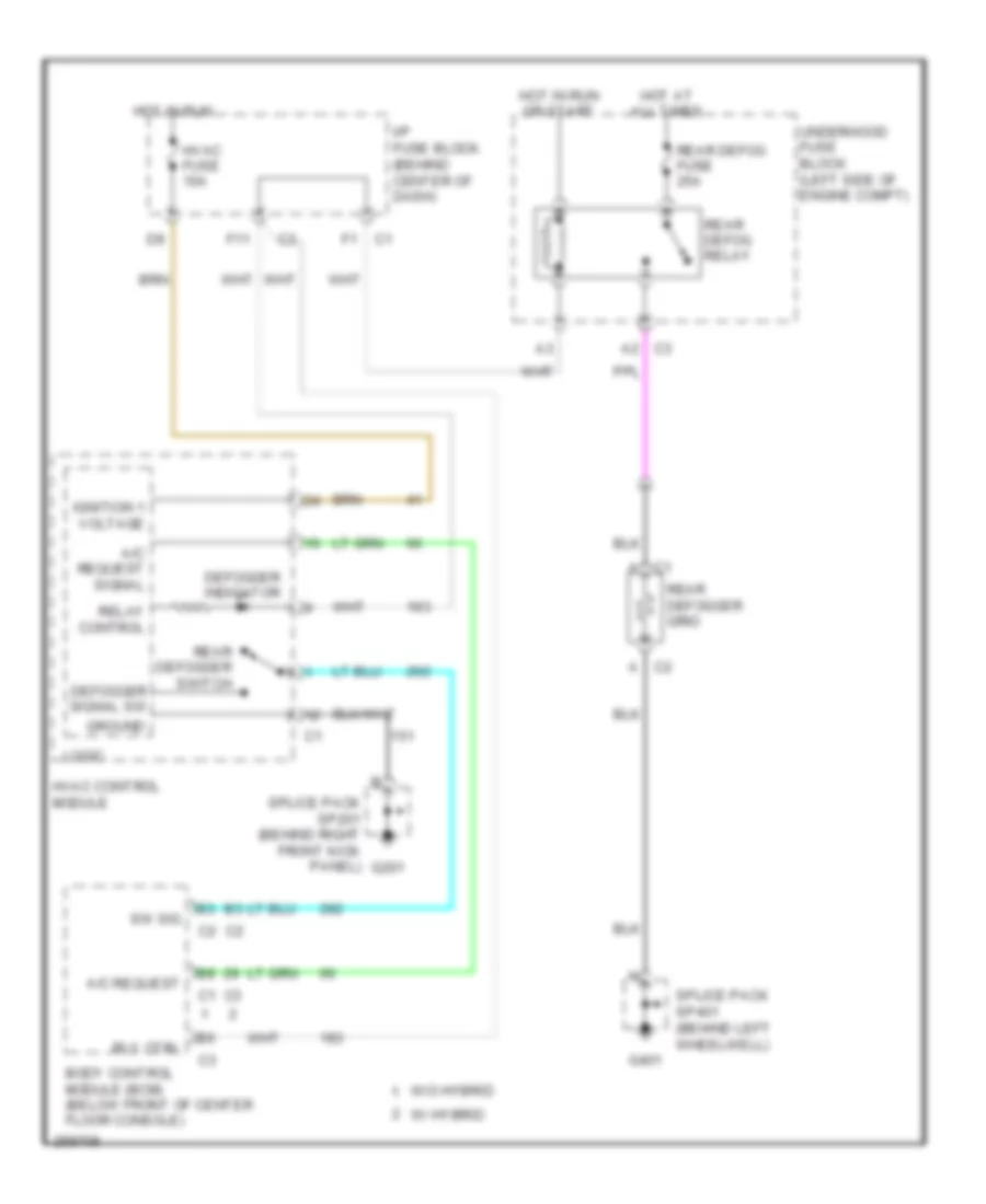
Defoggers Wiring Diagram for Saturn Vue Red Line 2007
 https://portal-diagnostov.com/license.html
Automotive Electricians Portal FZCO
Automotive Electricians Portal FZCO
https://portal-diagnostov.com/license.html
https://portal-diagnostov.com/license.html
Automotive Electricians Portal FZCO
Automotive Electricians Portal FZCOList of elements for Defoggers Wiring Diagram for Saturn Vue Red Line 2007:
- A/c request
- A/c request signal
- Body control module (bcm) (below front of center floor console)
- C1 a
- C2 a
- C3 a2
- Defogger indicator
- Defogger signal sw
- F11
- G201
- G401
- Ground
- Hot at all times
- Hot in run
- Hot in run or start
- Hvac control module
- Hvac fuse 10a
- I/p fuse block (behind center of dash)
- Ignition 1 voltage
- Logic
- Rear defog fuse 25a
- Rear defog relay
- Rear defogger grid
- Rear defogger switch
- Relay control
- Rly ctrl
- Splice pack sp201 (behind right front kick panel)
- Splice pack sp401 (behind left wheelwell)
- Sw sig
- Underhood fuse block (left side of engine compt)
- W/ hybrid
- W/o hybrid
ELECTRONIC POWER STEERING
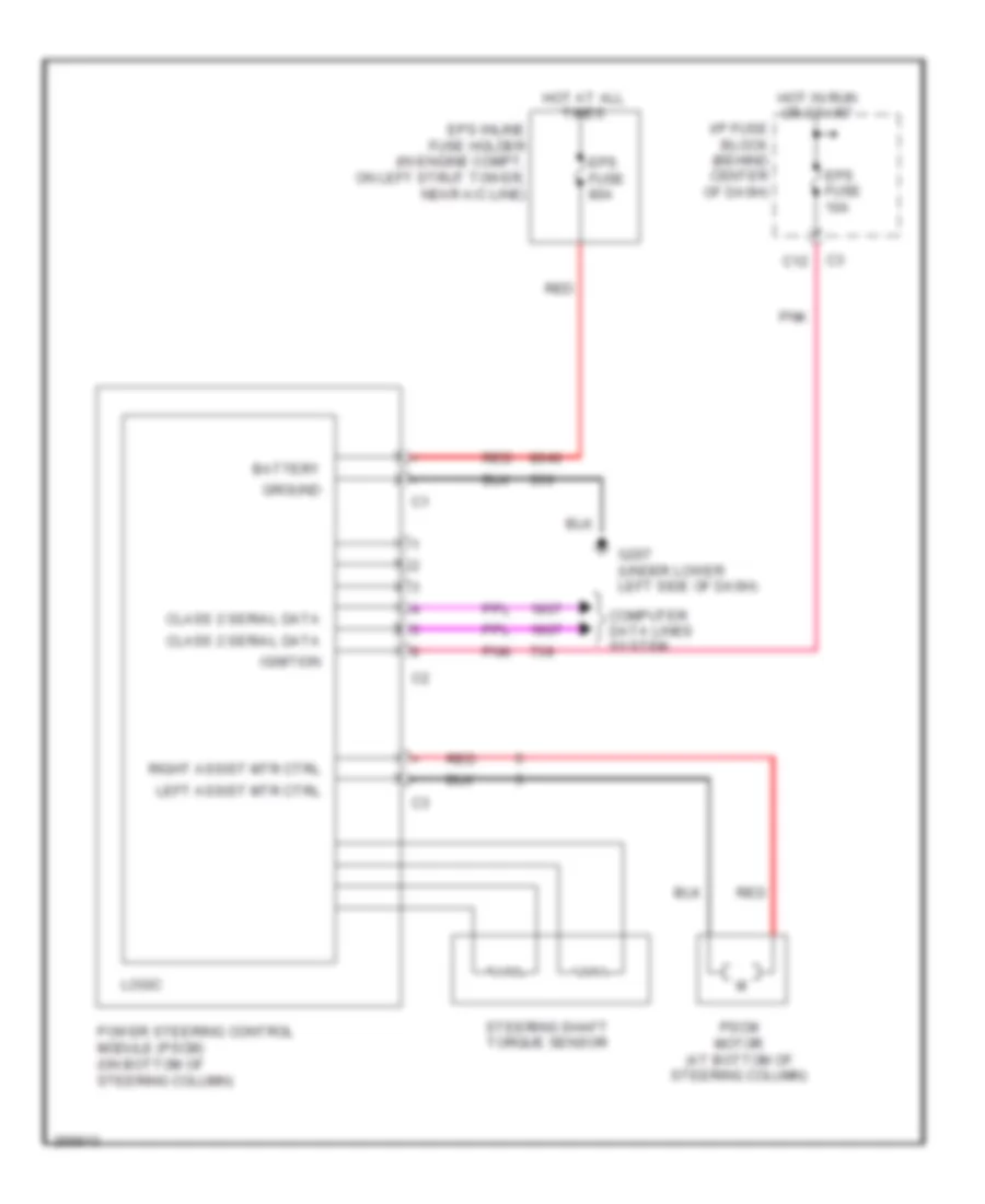
Electronic Power Steering Wiring Diagram for Saturn Vue Red Line 2007
 https://portal-diagnostov.com/license.html
Automotive Electricians Portal FZCO
Automotive Electricians Portal FZCO
https://portal-diagnostov.com/license.html
https://portal-diagnostov.com/license.html
Automotive Electricians Portal FZCO
Automotive Electricians Portal FZCOList of elements for Electronic Power Steering Wiring Diagram for Saturn Vue Red Line 2007:
- Battery
- C12
- Class 2 serial data
- Computer data lines system
- Eps fuse 10a
- Eps fuse 80a
- Eps inline fuse holder (in engine compt, on left strut tower, near a/c line)
- G207 (under lower left side of dash)
- Ground
- Hot at all times
- Hot in run or start
- I/p fuse block (behind center of dash)
- Ignition
- Left assist mtr ctrl
- Logic
- Pnk
- Power steering control module (pscm) (on bottom of steering column)
- Pscm motor (at bottom of steering column)
- Red
- Right assist mtr ctrl
- Steering shaft torque sensor
ENGINE PERFORMANCE
2.2L VIN D
2.2L VIN D, Engine Performance Wiring Diagram (1 of 3) for Saturn Vue Red Line 2007
 https://portal-diagnostov.com/license.html
Automotive Electricians Portal FZCO
Automotive Electricians Portal FZCO
https://portal-diagnostov.com/license.html
https://portal-diagnostov.com/license.html
Automotive Electricians Portal FZCO
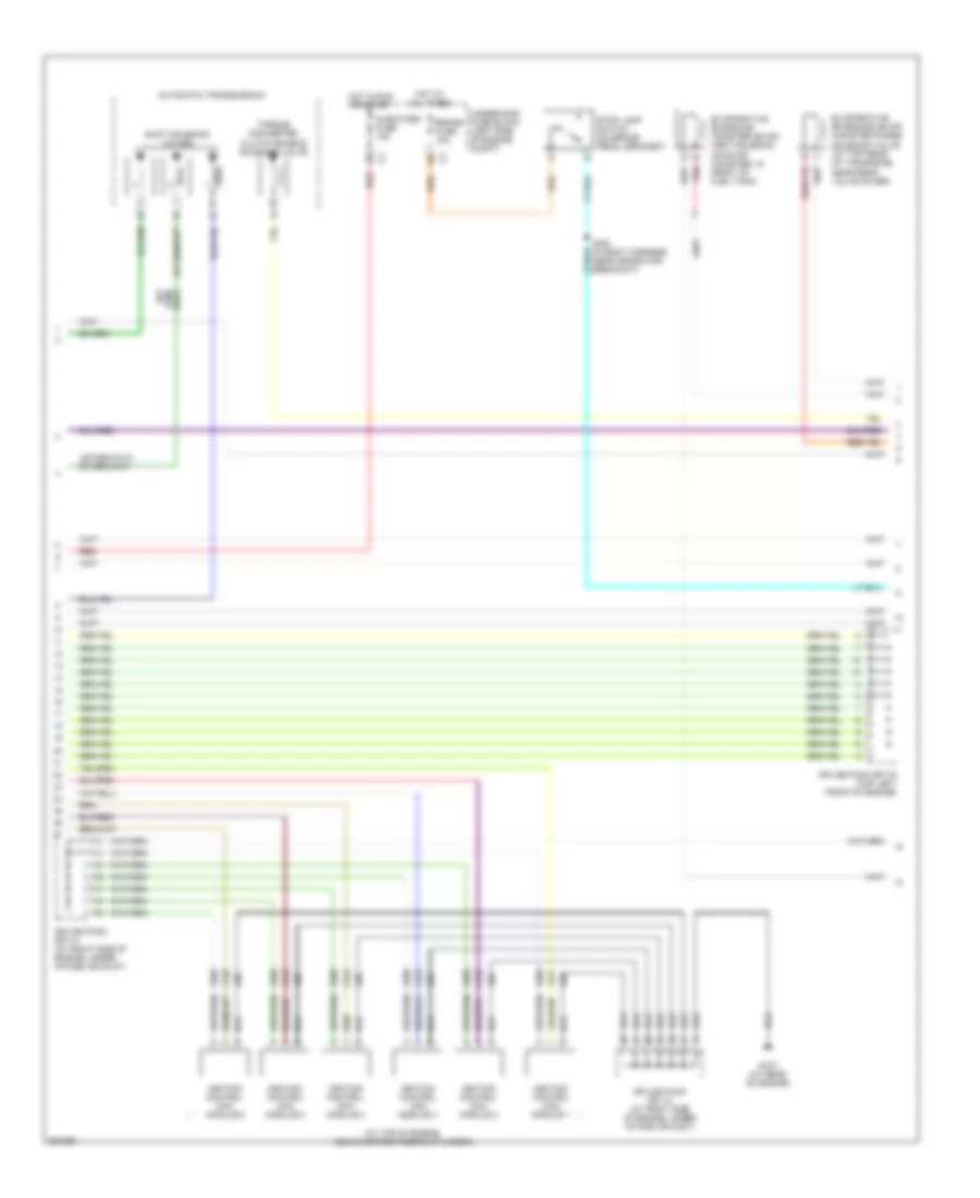
Automotive Electricians Portal FZCOList of elements for 2.2L VIN D, Engine Performance Wiring Diagram (1 of 3) for Saturn Vue Red Line 2007:
- (at left rear of engine) g105
- (in a/c high side pressure line) a/c refrigerant pressure sensor
- (m/t)
- A/c press +5v
- A/c press lo
- A/c press sig
- A/c relay
- A12
- Accelerator pedal position (app) sensor (on accelerator pedal linkage arm)
- Air conditioning system cooling fans system
- App 1 low ref
- App 1 sig
- App 2 low ref
- App 2 sig
- App1 5v ref b
- App2 5v ref a
- B12
- Back-up fuse 10a
- Battery
- Body control module (bcm) (below front of center floor console)
- Brake fuse 15a
- Can high
- Can low
- Class 2 (ecm)
- Class 2 serial data
- Computer data lines system
- Cooling fans system
- Cruise control system
- Cruise fuse 2a
- Cruise release switch (top of brake pedal assembly)
- Cruz on/off
- Cruz res/acl
- Cruz set/cst
- Data link connector (dlc) (lower left side of dash)
- Ecm/tcm fuse 10a
- Electronic brake control module (ebcm) (near left front shock tower)
- Engine control module (ecm) (right side of engine compartment)
- Engine oil pressure (eop) switch (on engine block, near oil filter)
- Exterior lights system
- Fuel relay
- G105 (at left rear of engine)
- Gnd
- Hi rly ctrl
- Hot at all times
- Hot in run or start
- Ign 1
- Ign 1 fuse 10a
- Ignition
- Instrument panel cluster (ipc)
- Instrument panel fuse block (behind center of dash)
- Keyw seri data
- Logic
- Low rly ctrl
- Main relay
- Malfunction indicator lamp (mil)
- Mil control
- Oil press sig
- Pnk
- Power distribution system
- Powertrain fuse 10a
- Release sw
- S304 (in body harness, near cross car breakout)
- S314 (a/t)
- S315 (a/t)
- Stop lamp sw
- Stop lamp switch (on brake pedal bracket)
- Tan
- Transmission control module (tcm) (a/t) (at left side of engine compt)
- Underhood fuse block (left side of engine compt)
- Up- shift ind
- Vehicle speed sensor (at rear of transmission)
- Vss
- Vss sig
- W/ abs
- W/o abs
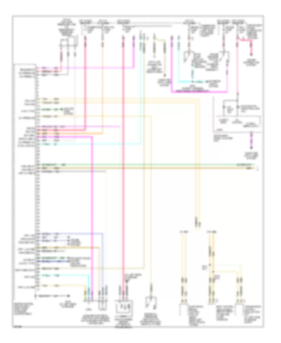
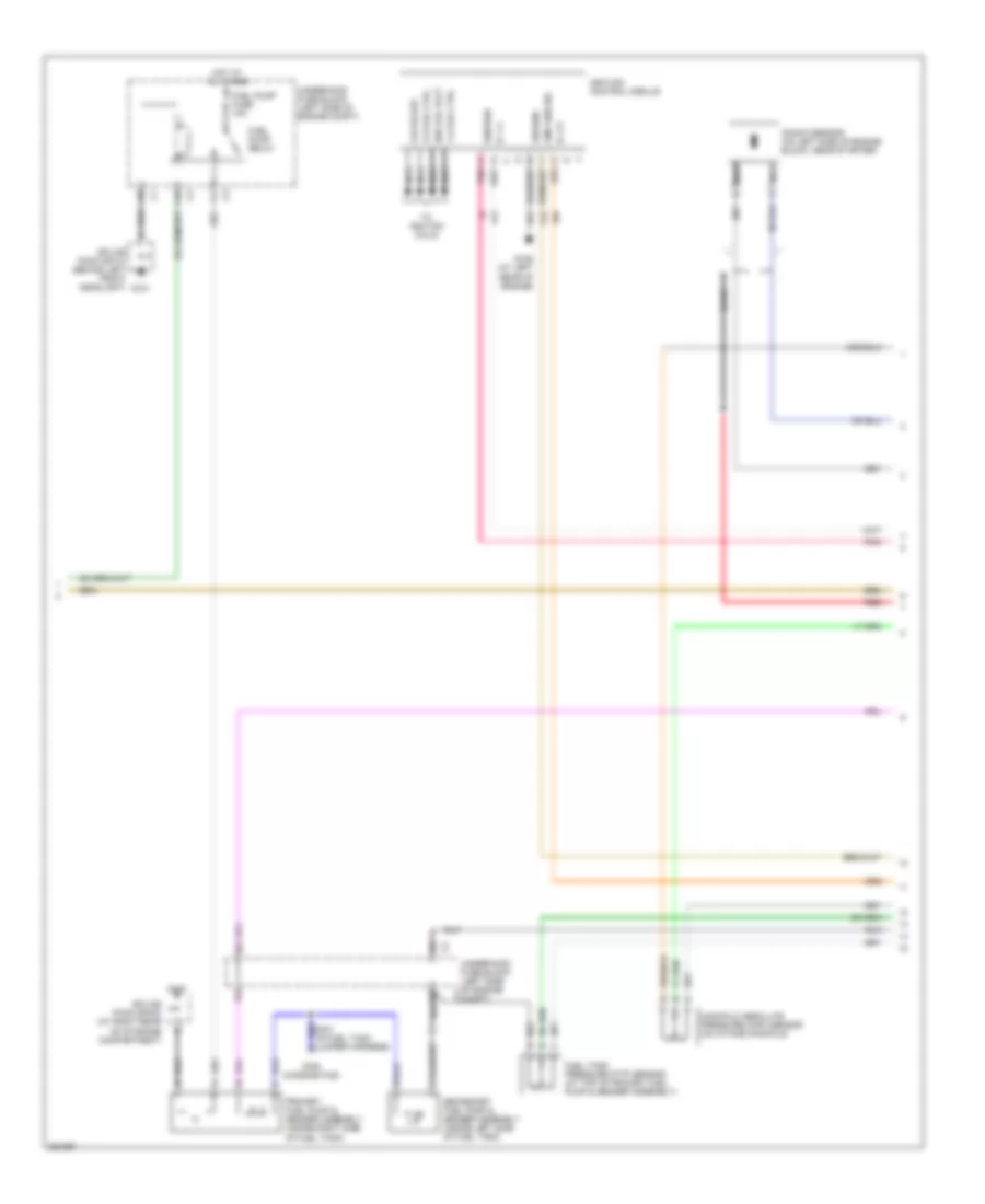
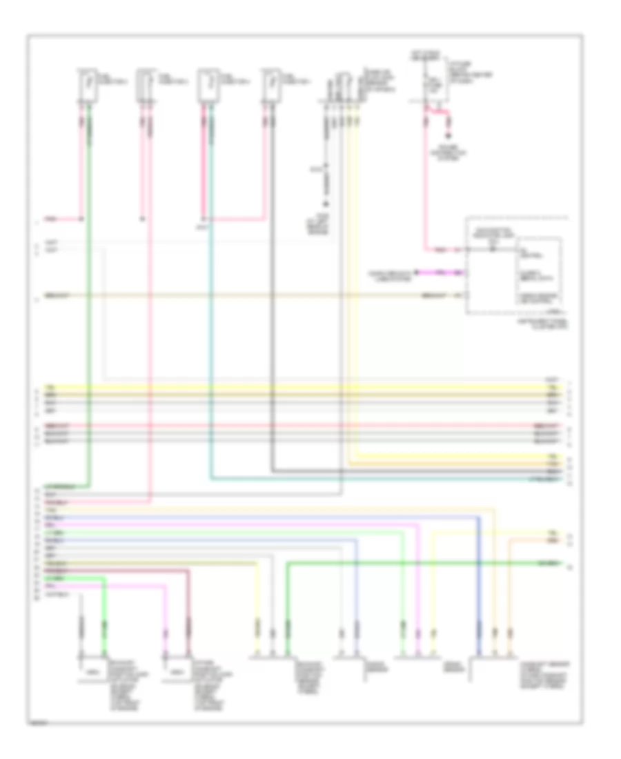
2.2L VIN D, Engine Performance Wiring Diagram (2 of 3) for Saturn Vue Red Line 2007
 https://portal-diagnostov.com/license.html
Automotive Electricians Portal FZCO
Automotive Electricians Portal FZCO
https://portal-diagnostov.com/license.html
https://portal-diagnostov.com/license.html
Automotive Electricians Portal FZCO
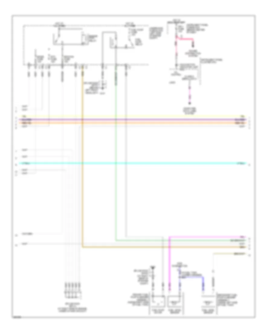
Automotive Electricians Portal FZCOList of elements for 2.2L VIN D, Engine Performance Wiring Diagram (2 of 3) for Saturn Vue Red Line 2007:
- (for diagnostics)
- 1-4 coil ctrl
- 2-3 coil ctrl
- A pnk
- A10
- Bare
- Cmp sen sig
- Csi pickup
- F11
- Fuel pump fuse 10a
- Fuel pump relay
- Fuel tank pressure (ftp) sensor (at top of primary fuel pump & sender assembly)
- G101
- G105 (at left rear of engine)
- G403
- Ground
- Hot at all times
- Ic 1-4
- Ic 2-3
- Ign coil volt
- Ignition
- Ignition control module
- Jumper harness)
- Knock sensor (on left side of engine block, near starter)
- Manifold absolute pressure (map) sensor (on intake manifold)
- Nca
- Pnk
- Primary fuel pump & sender assembly (inside right side of fuel tank)
- Red
- Secondary fuel pump & sender assembly (inside left side of fuel tank)
- Splice pack sp101 (behind left front headlight)
- Splice pack sp403 (at right rear of storage compartment)
- To ignition coils
- Underhood fuse block (left side of engine c3 compt)
- Underhood fuse block (left side of engine compt)
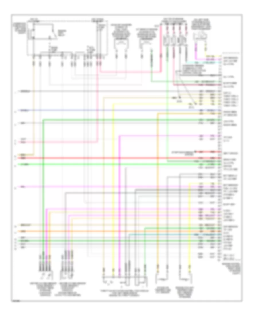
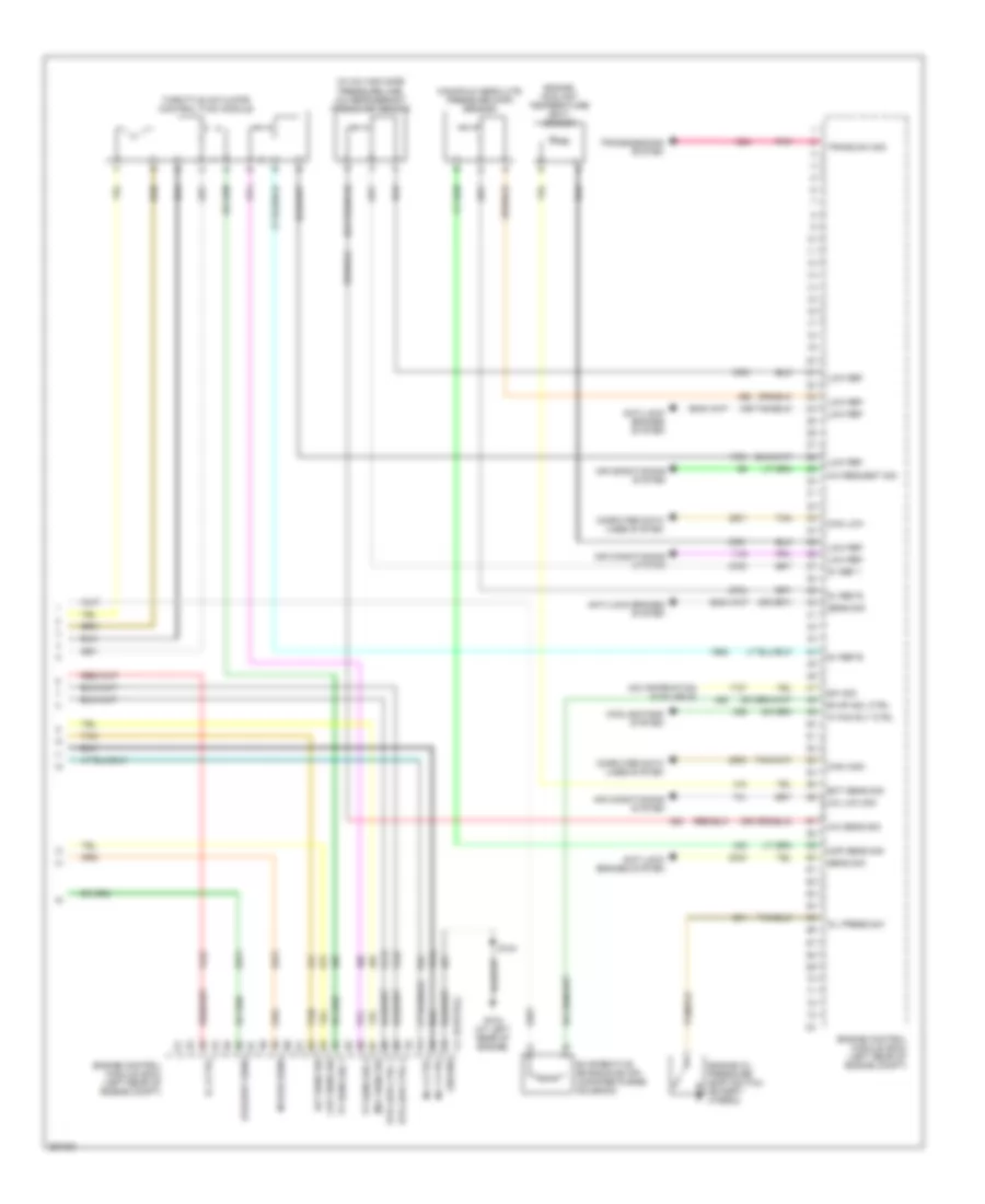
2.2L VIN D, Engine Performance Wiring Diagram (3 of 3) for Saturn Vue Red Line 2007
 https://portal-diagnostov.com/license.html
Automotive Electricians Portal FZCO
Automotive Electricians Portal FZCO
https://portal-diagnostov.com/license.html
https://portal-diagnostov.com/license.html
Automotive Electricians Portal FZCO
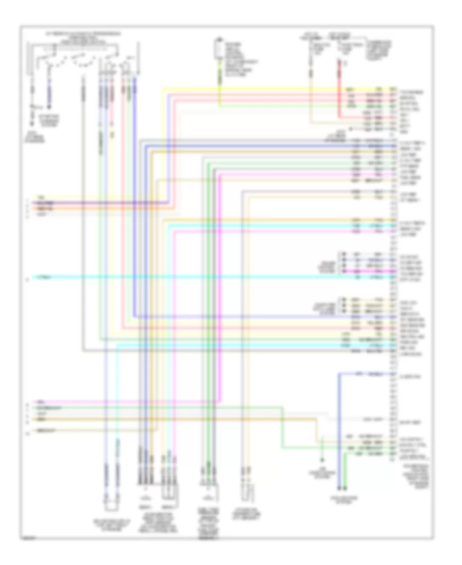
Automotive Electricians Portal FZCOList of elements for 2.2L VIN D, Engine Performance Wiring Diagram (3 of 3) for Saturn Vue Red Line 2007:
- (at rear of engine) evaporative emissions (evap) canister purge solenoid
- (ho2s) sensor 1 (on right rear of engine, in exhaust manifold)
- (ho2s) sensor 2
- (in engine harness, at breakout for throttle actuator control module)
- (in exhaust manifold, downstream of catalytic converter)
- (on evap canister, in front of fuel tank) evaporative emissions (evap) canister vent solenoid
- (on left side of engine block, above starter) crankshaft (ckp) position sensor
- (on top of engine, under intake runner) fuel injectors
- 5v ref a
- 5v ref b
- B11
- Ckp low ref
- Ckp sens sig
- Cmp sens sig
- Drain wire
- Ect sens lo
- Ect sens sig
- Emiss fuse 10a
- Engine control module (ecm) (right side of engine compt)
- Engine coolant temperature (ect) sensor (right rear of engine)
- Engine main relay
- Etc fuse 15a
- Evap purge
- Evap vent
- Ftp +5v
- Ftp sig
- Fuel lvl sig
- Gen turn sig
- Heated oxygen sensor
- Hi sen 2
- Hi sig 1
- Hot at all times
- Hot in run or start
- Htr sen 2
- Iat low ref
- Iat sens sig
- Ic 1-4
- Ic 2-3
- Ign 1 volt
- Ign/inj fuse 15a
- Inj 1 ctrl
- Inj 2 ctrl
- Inj 3 ctrl
- Inj 4 ctrl
- Intake air temperature (iat) sensor
- Knock sens
- Low ctrl
- Low ref
- Low sen 2
- Low sig 1
- Map lo
- Map sig
- Nca
- Pnk
- Red
- S101
- S109
- S110
- Starting/charging system
- Tan
- Throt ctrl 1
- Throt ctrl 2
- Throttle actuator control (tac) module (top left rear side of engine, on throttle body)
- Tp 1 low ref
- Tp 1 sig
- Tp 2 low ref
- Tp 2 sig
- Underhood fuse block (left side of engine compt)
2.4L VIN Z
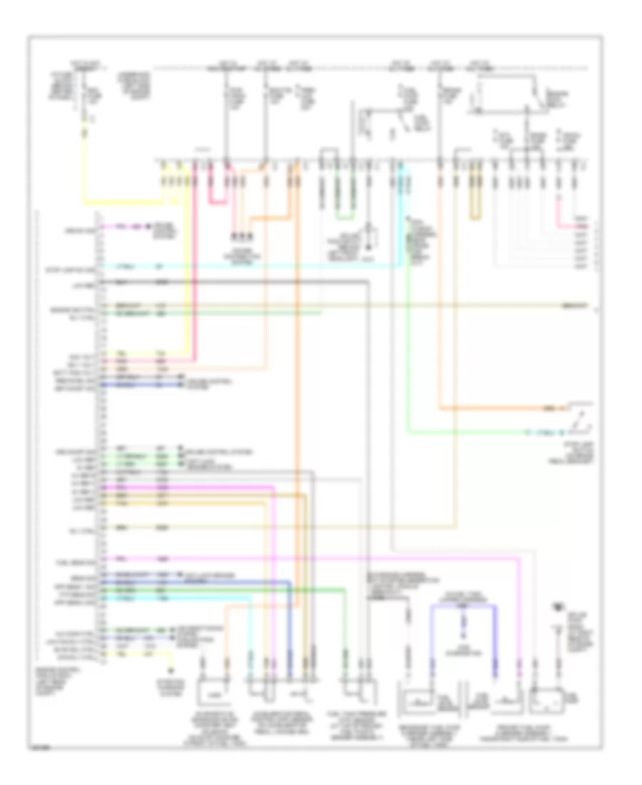
2.4L VIN Z, Engine Performance Wiring Diagram (1 of 4) for Saturn Vue Red Line 2007
 https://portal-diagnostov.com/license.html
Automotive Electricians Portal FZCO
Automotive Electricians Portal FZCO
https://portal-diagnostov.com/license.html
https://portal-diagnostov.com/license.html
Automotive Electricians Portal FZCO
Automotive Electricians Portal FZCOList of elements for 2.4L VIN Z, Engine Performance Wiring Diagram (1 of 4) for Saturn Vue Red Line 2007:
- (for diagnostics)
- (in engine harness, at starter generator control module breakout) s102
- (in fuel tank jumper harness) s401
- 5v ref
- 5v ref a
- 5v ref b
- A/c comp ctrl
- A10
- Acc volt
- Accelerator pedal position (app) sensor (on accelerator pedal linkage arm)
- Air conditioning system cooling fans system
- Anti-lock brakes system
- App sens 1 sig
- App sens 2 sig
- Batt pos volt
- Bcm fuse 10a
- Brake fuse 15a
- Cruise control system
- Crz on/off sig
- Crz sw sig
- D12
- Ecm/tcm fuse 10a
- Emiss fuse 10a
- Engine control module (ecm) (left rear of engine compt)
- Engine ind ctrl
- Engine main relay
- Etc fuse 15a
- Evap sol ctrl
- Evaporative emissions (evap) canister vent solenoid (on evap canister, in front of fuel tank)
- F10
- F11
- Ftp sens sig
- Fuel level sensor
- Fuel pump
- Fuel pump fuse 10a
- Fuel pump relay
- Fuel sens sig
- Fuel tank pressure (ftp) sensor (at top of primary fuel pump & sender assembly)
- G101
- G403
- Hot at all times
- Hot in acc or run
- Hot in run or start
- I/p fuse block (behind center of dash)
- Ign 1 volt
- Ign/inj fuse 15a
- Low fan rly ctrl
- Low ref
- Pnk
- Power distribution system
- Prem aud fuse 20a
- Primary fuel pump & sender assembly (inside right side of fuel tank)
- Pwr train fuse 10a
- Res/accel sig
- Rly ctrl
- Secondary fuel pump & sender assembly (inside left side of fuel tank)
- Sens sig
- Set/coast sig
- Splice pack sp101 (behind left front headlight)
- Splice pack sp403 (at right rear of storage compt)
- Starting/ charging system
- Stop lamp sw sig
- Stop lamp switch (on brake pedal bracket)
- Str rly ctrl
- Tan
- Underhood fuse block (left side of engine compt)
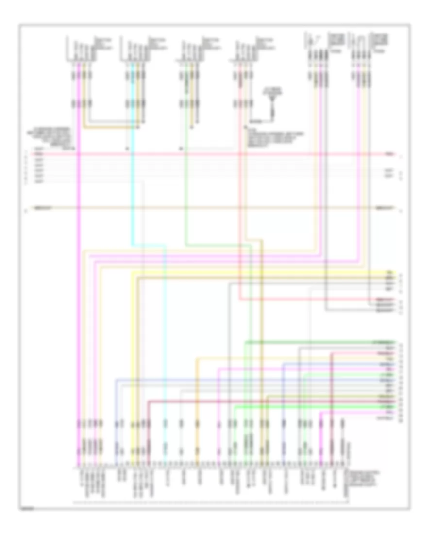
2.4L VIN Z, Engine Performance Wiring Diagram (2 of 4) for Saturn Vue Red Line 2007
 https://portal-diagnostov.com/license.html
Automotive Electricians Portal FZCO
Automotive Electricians Portal FZCO
https://portal-diagnostov.com/license.html
https://portal-diagnostov.com/license.html
Automotive Electricians Portal FZCO
Automotive Electricians Portal FZCOList of elements for 2.4L VIN Z, Engine Performance Wiring Diagram (2 of 4) for Saturn Vue Red Line 2007:
- (at rear of engine) g107
- (in engine harness, between ignition coil/ module #3 & ignition coil/ module #4 breakout) s137
- (partial)
- 5v ref 2
- 5v ref a
- Engine control module (ecm) (left rear of engine compt)
- Exhaust sol
- Ground
- Heated oxygen sensor (ho2s)
- Hi sens sig 2
- Hi sig sens 1
- Ic 1 ctrl
- Ic 2 ctrl
- Ic 3 ctrl
- Ic 4 ctrl
- Ign 1 volt
- Ignition coil/ module 1
- Ignition coil/ module 2
- Ignition coil/ module 3
- Ignition coil/ module 4
- Inj 2 ctrl
- Inj 3 ctrl
- Intake sol
- Ks sig
- Low ref
- Low sig sens 1
- Low sig sens 2
- Nca
- Phaser 2 ctrl
- Phaser 3 ctrl
- Pnk
- S138
- S139 (in engine harness, between ignition coil/ module #2 & ignition coil/ module #3 breakout)
- Tac mtr ctrl 1
- Tac mtr ctrl 2
- Tan
2.4L VIN Z, Engine Performance Wiring Diagram (3 of 4) for Saturn Vue Red Line 2007
 https://portal-diagnostov.com/license.html
Automotive Electricians Portal FZCO
Automotive Electricians Portal FZCO
https://portal-diagnostov.com/license.html
https://portal-diagnostov.com/license.html
Automotive Electricians Portal FZCO
Automotive Electricians Portal FZCOList of elements for 2.4L VIN Z, Engine Performance Wiring Diagram (3 of 4) for Saturn Vue Red Line 2007:
- Camshaft sensor (hybrid) intake camshaft position sensor (except hybrid)
- Check engine ind control
- Class 2 serial data
- Computer data lines system
- Crank sensor
- Exhaust camshaft position (cmp) actuator solenoid (except hybrid) (top front of engine)
- Exhaust camshaft position sensor (except hybrid)
- Fuel injector 1
- Fuel injector 2
- Fuel injector 3
- Fuel injector 4
- G105 (at left rear of engine)
- Ground
- Hot in run or start
- I/p fuse block (behind center of dash)
- Ign 1 fuse 10a
- Ign 1 volt
- Instrument panel cluster (ipc)
- Intake camshaft position (cmp) actuator solenoid (except hybrid) (top front of engine)
- Knock sensor
- Logic
- Malfunction indicator lamp (mil)
- Mass air flow (maf) sensor (in air box)
- Mil control
- Pnk
- Power distribution system
- S101
- Sens sig
- Tan
2.4L VIN Z, Engine Performance Wiring Diagram (4 of 4) for Saturn Vue Red Line 2007
 https://portal-diagnostov.com/license.html
Automotive Electricians Portal FZCO
Automotive Electricians Portal FZCO
https://portal-diagnostov.com/license.html
https://portal-diagnostov.com/license.html
Automotive Electricians Portal FZCO
Automotive Electricians Portal FZCOList of elements for 2.4L VIN Z, Engine Performance Wiring Diagram (4 of 4) for Saturn Vue Red Line 2007:
- (in a/c high side pressure line) a/c refrigerant pressure sensor
- (no information available)
- (partial)
- 5v ref 1
- 5v ref b
- A/c low sig
- A/c request sig
- A/c sens sig
- Air conditioning system
- Anti-lock brakes system
- Can high
- Can low
- Ckp sens sig
- Computer data lines system
- Cooling fans system
- Ect sens sig
- Engine control module (ecm) (left rear of engine compt)
- Engine coolant temperature (ect) sensor
- Engine oil pressure (eop) switch (except hybrid)
- Evap sol ctrl
- Evaporative emission (evap) canister purge solenoid
- Exhaust sens
- G105 (at left rear of engine)
- Ground
- Hi fan rly ctrl
- Htr low ctrl 1
- Htr low ctrl 2
- Iat sens sig
- Ic 2 ctrl
- Inj 1 ctrl
- Inj 4 ctrl
- Intake sens
- Low ref
- Maf sens sig
- Manifold absolute pressure (map) sensor
- Map sens sig
- Oil press sw
- Pnk
- S104
- Sens sig
- Sw sig
- Tan
- Throttle actuator control (tac) module
- Tp sens sig 1
- Tp sens sig 2
- Trans sw sig
- Transmissions system
3.5L VIN 4
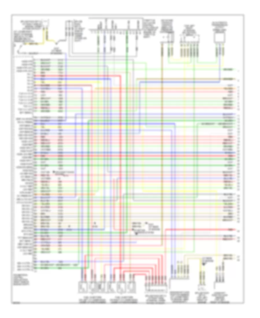
3.5L VIN 4, Engine Performance Wiring Diagram (1 of 5) for Saturn Vue Red Line 2007
 https://portal-diagnostov.com/license.html
Automotive Electricians Portal FZCO
Automotive Electricians Portal FZCO
https://portal-diagnostov.com/license.html
https://portal-diagnostov.com/license.html
Automotive Electricians Portal FZCO
Automotive Electricians Portal FZCOList of elements for 3.5L VIN 4, Engine Performance Wiring Diagram (1 of 5) for Saturn Vue Red Line 2007:
- ks sig
- (at lower right front of engine, above oil filter) rocker arm oil pressure switch
- (at rear of engine) g107
- (in automatic transmission) output speed (oss) sensor
- (on intake manifold) manifold absolute pressure (map)sensor
- (top left front of engine) splice pack sp115
- 3rd cltch sw
- 4th cltch sw
- 5 volt ref
- A/c ref sig
- Air conditioning system
- Camshaft position (cmp) sensor (top left front of engine)
- Ckp sens a
- Ckp sens b
- Cmp pos sig
- Crankshaft (ckp) position sensor (at lower front of engine, near crankshaft)
- Ect sens 1
- Ect sens 2
- Egr valve sig
- Etc ctrl
- Etc sig
- Fuel injectors (on left cylinder bank, under intake runners)
- Fuel injectors (on right cylinder bank, under intake runners)
- G107 (at rear of engine)
- Gen field
- Gen turn on
- Ground
- Ho2s htr
- Ho2s htr low
- Ho2s input
- Ho2s low
- Ho2s low ref
- Ho2s pump
- Ho2s ref
- Ho2s sig
- Ho2s sig sens
- Iat sens 2
- Ign 1
- Ign coil 1
- Ign coil 2
- Ign coil 3
- Ign coil 4
- Ign coil 5
- Ign coil 6
- Inhibit mtr
- Inj 1
- Inj 2
- Inj 3
- Inj 4
- Inj 5
- Inj 6
- Iss high sig
- Low ref
- Map sens sig
- Mtr inhibit
- Nca
- Oil press sw
- Oss high sig
- Powertrain control module (pcm) (right side of engine compt)
- Ra oil press
- Red
- S134
- S135
- Splice pack sp113 (at right side of engine, under intake air duct)
- Splice pack sp114 (at right side of engine, under intake air duct)
- Splice pack sp115 (top left front of engine)
- Ssv hi ctrl 1
- Ssv hi ctrl 2
- Ssv hi ctrl 3
- Starting/ charging system
- Tcc vlv
- Tcc vlv low
- Tft sens sig
- Throttle actuator control (tac) module (at rear of engine, on throttle body)
- Tls vlv hi a
- Tls vlv hi b
- Tls vlv lo a
- Tls vlv lo b
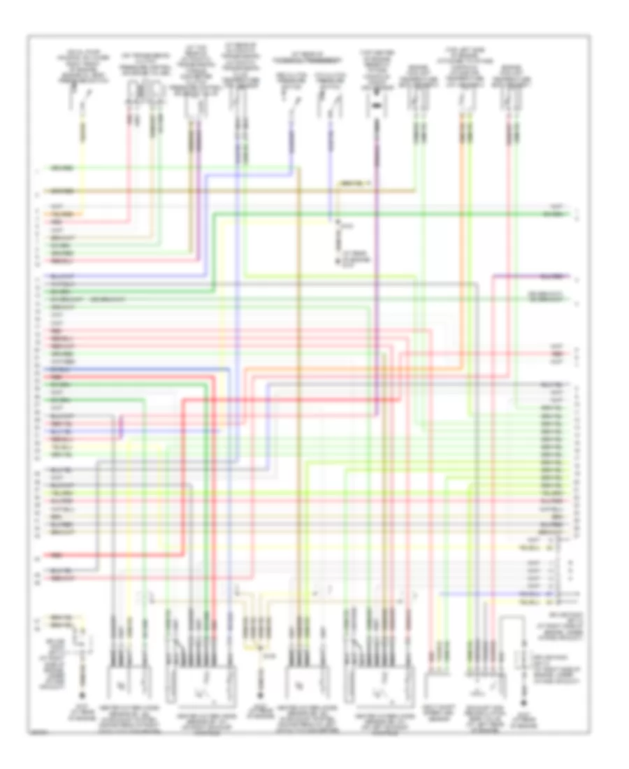
3.5L VIN 4, Engine Performance Wiring Diagram (2 of 5) for Saturn Vue Red Line 2007
 https://portal-diagnostov.com/license.html
Automotive Electricians Portal FZCO
Automotive Electricians Portal FZCO
https://portal-diagnostov.com/license.html
https://portal-diagnostov.com/license.html
Automotive Electricians Portal FZCO
Automotive Electricians Portal FZCOList of elements for 3.5L VIN 4, Engine Performance Wiring Diagram (2 of 5) for Saturn Vue Red Line 2007:
- (at rear of automatic transmission)
- (at rear of automatic transmission) automatic transmission fluid temperature (tft) sensor
- (at rear of engine) g107
- (at top rear of automatic transmission)
- (on oil pump housing, on lower right front of engine) engine oil (eop) pressure switch
- (on transmission) clutch pressure control solenoid valves
- (top center of engine, beneath intake manifold) knock (ks) sensor
- (top left side of engine, attached to intake manifold) intake air temperature (iat) sensor 2
- 3rd clutch pressure switch
- 4th clutch pressure switch
- Engine coolant temperature (ect) sensor 1
- Engine coolant temperature (ect) sensor 2
- Exhaust gas recirculation (egr) valve (at left rear of engine)
- G107 (at rear of engine)
- Heated oxygen (ho2s) sensor (b1, s1) (on right exhaust manifold)
- Heated oxygen (ho2s) sensor (b1, s2) (in exhaust system, downstream of right catalytic converter)
- Heated oxygen (ho2s) sensor (b2, s1) (on left exhaust manifold)
- Heated oxygen (ho2s) sensor (b2, s2) (in exhaust system, downstream of left catalytic converter)
- Input shaft speed (iss) sensor
- Nca
- Red
- S134
- S135
- Splice pack sp113 (at right side of engine, under intake air duct)
- Splice pack sp114 (at right side of engine, under intake air duct)
- Torque converter clutch pressure control solenoid valve
3.5L VIN 4, Engine Performance Wiring Diagram (3 of 5) for Saturn Vue Red Line 2007
 https://portal-diagnostov.com/license.html
Automotive Electricians Portal FZCO
Automotive Electricians Portal FZCO
https://portal-diagnostov.com/license.html
https://portal-diagnostov.com/license.html
Automotive Electricians Portal FZCO
Automotive Electricians Portal FZCOList of elements for 3.5L VIN 4, Engine Performance Wiring Diagram (3 of 5) for Saturn Vue Red Line 2007:
- (at top of engine, above corresponding cylinder)
- Automatic transmission
- Brake fuse 15a
- Evaporative emissions (evap) canister purge solenoid valve (at top rear of the engine, near rear valve cover)
- Evaporative emissions canister (evap) vent solenoid (on evap canister, in front of fuel tank)
- G107 (at rear of engine)
- Hot at all times
- Hot in run or start
- Ignition control (icm) module 1
- Ignition control (icm) module 2
- Ignition control (icm) module 3
- Ignition control (icm) module 4
- Ignition control (icm) module 5
- Ignition control (icm) module 6
- Injectors fuse 10a
- Pnk
- Red
- S304 (in body harness, near cross car breakout)
- Shift solenoid valves
- Splice pack sp113 (at right side of engine, under intake air duct)
- Splice pack sp114 (at right side of engine, under intake air duct)
- Splice pack sp115 (top left front of engine)
- Stop lamp switch (on brake pedal bracket)
- Torque converter clutch enable solenoid valve
- Underhood fuse block (left side of engine compt)
3.5L VIN 4, Engine Performance Wiring Diagram (4 of 5) for Saturn Vue Red Line 2007
 https://portal-diagnostov.com/license.html
Automotive Electricians Portal FZCO
Automotive Electricians Portal FZCO
https://portal-diagnostov.com/license.html
https://portal-diagnostov.com/license.html
Automotive Electricians Portal FZCO
Automotive Electricians Portal FZCOList of elements for 3.5L VIN 4, Engine Performance Wiring Diagram (4 of 5) for Saturn Vue Red Line 2007:
- (for diagnostics)
- Class 2 serial data
- Computer data lines system
- D10
- D11
- Ecm/cam fuse 15a
- Emiss fuse 10a
- Engine main relay
- Etc fuse 15a
- Fuel level sensor
- Fuel pump fuse 10a
- Fuel pump motor
- Fuel pump relay
- G101
- G403
- Hot at all times
- Hot in run or start
- Ign 1 fuse 10a
- Instrument panel cluster (ipc)
- Instrument panel fuse block (behind center of dash)
- Logic
- Malfunction indicator lamp (mil)
- Mil control
- Pnk
- Power distribution system
- Primary fuel pump & sender assembly (inside right side of fuel tank)
- S401
- Secondary fuel pump & sender assembly (inside left side of fuel tank)
- Splice pack sp101 (behind left front headlight)
- Splice pack sp113 (at right side of engine, under intake air duct)
- Splice pack sp403 (at right rear of storage compt)
- Underhood fuse block (left side of engine compt)
3.5L VIN 4, Engine Performance Wiring Diagram (5 of 5) for Saturn Vue Red Line 2007
 https://portal-diagnostov.com/license.html
Automotive Electricians Portal FZCO
Automotive Electricians Portal FZCO
https://portal-diagnostov.com/license.html
https://portal-diagnostov.com/license.html
Automotive Electricians Portal FZCO
Automotive Electricians Portal FZCOList of elements for 3.5L VIN 4, Engine Performance Wiring Diagram (5 of 5) for Saturn Vue Red Line 2007:
- (at rear of automatic transmission) park/neutral position (pnp) switch
- (at rear of engine)
- 2 drive sig
- 2nd gear sig
- 5 volt ref
- 5 volt ref a
- 5 volt ref b
- A/c cmp rly
- Accelerator pedal position (app) sensor (on accelerator pedal linkage arm)
- Air conditioning system
- Batt
- Can hi
- Can low
- Cc on sw
- Cc res/acc
- Cc set/cst
- Computer data lines system
- Cooling fans system
- Cruise control system
- Drive sig
- Ecm/tcm fuse 10a
- Egr sol
- Evap sol
- Evap vent
- F10
- Ftp sens
- Fuel sens
- Fuel tank pressure sensor (at top of primary fuel pump & sender assembly)
- G107
- G107 (at rear of engine)
- Gnd
- Hi spd fan
- Hot at all times
- Hot in run or start
- Iat sens 1
- Ign 1
- Intake air temperature (iat) sensor 1
- Ist gear sig
- Low ref
- Low spd fan
- Main rly ctrl
- Nca
- Neutral sig
- Park sig
- Powertrain control module (pcm) (right side of engine compt)
- Pump rly
- Pwr train fuse 10a
- Ra oil sol
- Red
- Rev sig
- Rocker arm oil control solenoid (at lower right front of engine, near oil filter)
- S112
- Sens 1
- Sens 1 sig
- Sens 2
- Sens 2 sig
- Ser data
- Splice pack sp115 (top left front of engine)
- Starting/ charging system
- Stp lp sw
- Tan
- Tcc brk sw
- Tcc enable
- Underhood fuse block (left side of engine compt)
EXTERIOR LIGHTS
Back-up Lamps Wiring Diagram for Saturn Vue Red Line 2007
 https://portal-diagnostov.com/license.html
Automotive Electricians Portal FZCO
Automotive Electricians Portal FZCO
https://portal-diagnostov.com/license.html
https://portal-diagnostov.com/license.html
Automotive Electricians Portal FZCO
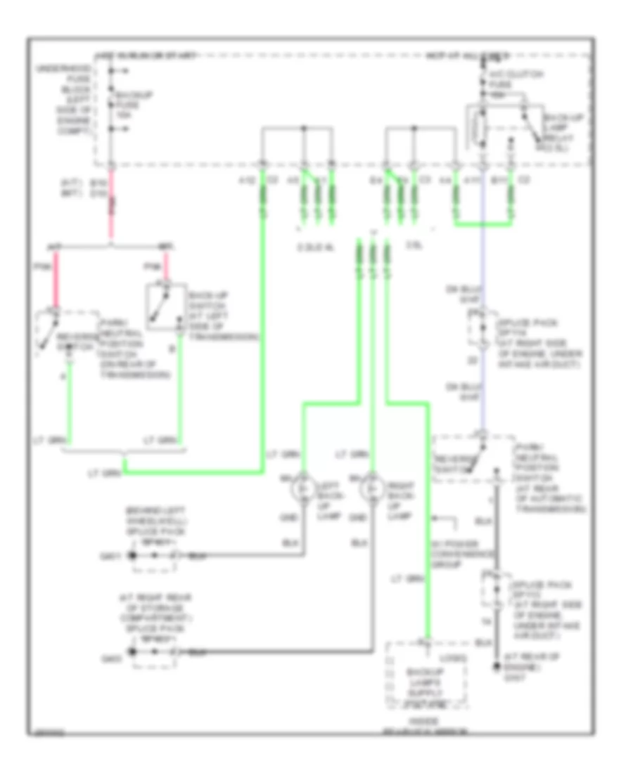
Automotive Electricians Portal FZCOList of elements for Back-up Lamps Wiring Diagram for Saturn Vue Red Line 2007:
- (a/t) (m/t)
- (at rear of engine) g107
- (at right rear of storage compartment) splice pack sp403
- (behind left wheelwell) splice pack sp401
- 2.2l/2.4l
- 3.5l
- A/c clutch fuse 10a
- A/t
- A11
- A12
- B10 d10
- B11
- Back-up lamp relay (3.5l)
- Back-up switch (at left side of transmission)
- Backup fuse 10a
- G401
- G403
- Gnd
- Hot at all times
- Hot in run or start
- Inside rearview mirror
- Left back- up lamp
- Logic
- M/t
- Maj
- Park/ neutral position switch (at rear of automatic transmission)
- Park/ neutral position switch (on rear of transmission)
- Pnk
- Reverse switch
- Right back- up lamp
- Splice pack sp113 (at right side of engine, under intake air duct)
- Splice pack sp114 (at right side of engine, under intake air duct)
- Underhood fuse block (left side of engine compt)
- W/ power convenience group
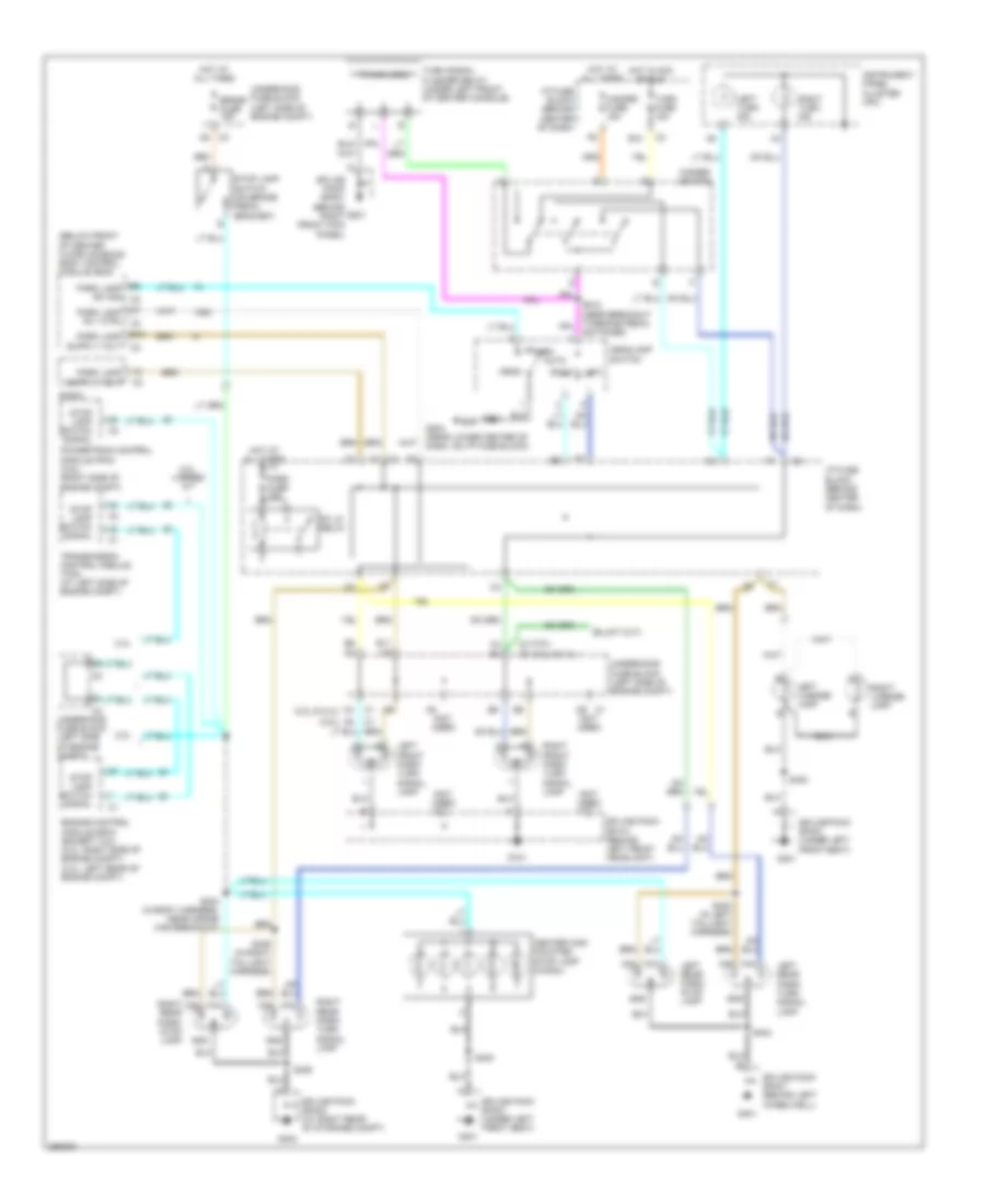
Exterior Lamps Wiring Diagram, with Autolamps for Saturn Vue Red Line 2007
 https://portal-diagnostov.com/license.html
Automotive Electricians Portal FZCO
Automotive Electricians Portal FZCO
https://portal-diagnostov.com/license.html
https://portal-diagnostov.com/license.html
Automotive Electricians Portal FZCO
Automotive Electricians Portal FZCOList of elements for Exterior Lamps Wiring Diagram, with Autolamps for Saturn Vue Red Line 2007:
- (2.2l & 2.4l)
- (3.5l)
- (below front of center floor console) body control module (bcm)
- (not used)
- 2.2l
- 2.2l, 4 speed a/t
- 2.4l
- A7 park lamp rly ctrl c3
- Auto
- B6 park lamp sw sig c2
- Brake fuse 15a
- C2 c2
- Center high mounted stop lamp (chmsl)
- D9 c1
- E10
- E11
- Engine control module (ecm) (except 3.5l) (2.2l: right side of engine compt) (2.4l: left rear of engine compt)
- G101
- G201
- G203 (near lower center of dash, on i/p fuse block)
- G301
- G401
- G403
- Gnd
- Hazard fuse 15a
- Hazard switch
- Head
- Headlamp switch
- Hot at all times
- Hot in acc or run
- I/p fuse block (behind center of dash)
- Instrument panel cluster (ipc)
- Left
- Left front park/ turn signal lamp
- Left license lamp
- Left rear park/ stop lamp
- Left rear park/ turn signal lamp
- Left turn ind
- Maj
- Min
- Park
- Park fuse 10a
- Pk lp relay
- Powertrain control module (pcm) (3.5l) (right side of engine compt)
- Radio
- Right
- Right front park/ turn signal lamp
- Right license lamp
- Right rear park/ stop lamp
- Right rear park/ turn signal lamp
- Right turn ind
- S304 (in body harness, near cross car breakout)
- S400
- S403 (in left taillight harness)
- S404
- S405 (in right taillight harness)
- S406
- Splice pack sp101 (behind left front headlight)
- Splice pack sp201 (behind right front kick panel)
- Splice pack sp301 (under left front seat)
- Splice pack sp401 (behind left wheelwell)
- Splice pack sp403 (at right rear of storage compt)
- Stop lamp switch (on brake pedal bracket)
- Stop lamp switch signal
- Timing logic
- Transmission control module (tcm) (at left side of engine compt)
- Turn fuse 15a
- Turn signal flasher relay (under left front of center console)
- Underhood fuse block (left side of engine compt)
Exterior Lamps Wiring Diagram, without Autolamps for Saturn Vue Red Line 2007
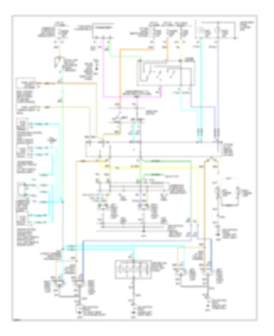 https://portal-diagnostov.com/license.html
Automotive Electricians Portal FZCO
Automotive Electricians Portal FZCO
https://portal-diagnostov.com/license.html
https://portal-diagnostov.com/license.html
Automotive Electricians Portal FZCO
Automotive Electricians Portal FZCOList of elements for Exterior Lamps Wiring Diagram, without Autolamps for Saturn Vue Red Line 2007:
- (2.2l & 2.4l)
- (3.5l)
- (near breakout to brake pedal switches) s212
- (not used)
- 2.2l
- 2.2l, 4 speed a/t
- 2.4l
- A5 c1
- B10
- Body control module (bcm) (below front of center floor console)
- Brake fuse 15a
- C3 c1
- C4 e4
- C9 c9
- Center high mounted stop lamp (chmsl)
- D9 c1
- E10
- E6 d1
- Engine control module (ecm) (except 3.5l) (2.2l: right side of engine compt) (2.4l: left rear of engine compt)
- G101
- G201
- G301
- G401
- G403
- Gnd
- Hazard fuse 15a
- Hazard switch
- Head
- Headlamp switch
- Hot at all times
- Hot in run or acc
- I/p fuse block (behind center of dash)
- Instrument panel cluster (ipc)
- Left
- Left front park/ turn signal lamp
- Left license lamp
- Left rear park/ stop lamp
- Left rear park/ turn signal lamp
- Left turn ind
- Maj
- Min
- Off
- Park
- Park fuse 10a
- Powertrain control module (pcm) (3.5l) (right side of engine compt)
- Radio
- Right
- Right front park/ turn signal lamp
- Right license lamp
- Right rear park/ stop lamp
- Right rear park/ turn signal lamp
- Right turn ind
- S304 (in body harness, near cross car breakout)
- S400
- S403 (in left taillight harness)
- S404
- S405 (in right taillight harness)
- S406
- Splice pack sp101 (behind left front headlight)
- Splice pack sp201 (behind right front kick panel)
- Splice pack sp301 (under left front seat)
- Splice pack sp401 (behind left wheelwell)
- Splice pack sp403 (at right rear of storage compt)
- Stop lamp switch (on brake pedal bracket)
- Stop lamp switch signal
- Timing logic
- Transmission control module (tcm) (at left side of engine compt)
- Turn fuse 15a
- Turn signal flasher relay
- Underhood fuse block (left side of engine compt)
GROUND DISTRIBUTION
Ground Distribution Wiring Diagram (1 of 3) for Saturn Vue Red Line 2007
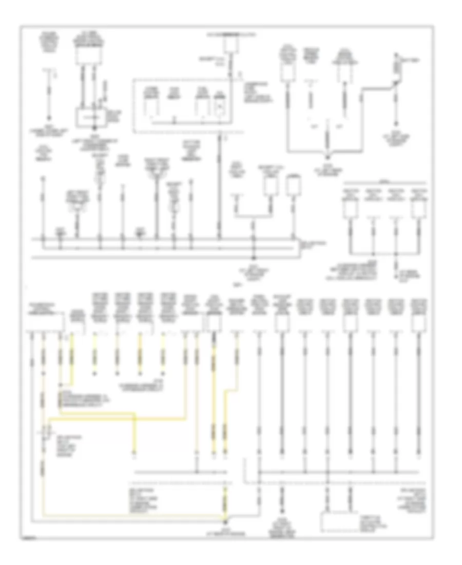 https://portal-diagnostov.com/license.html
Automotive Electricians Portal FZCO
Automotive Electricians Portal FZCO
https://portal-diagnostov.com/license.html
https://portal-diagnostov.com/license.html
Automotive Electricians Portal FZCO
Automotive Electricians Portal FZCOList of elements for Ground Distribution Wiring Diagram (1 of 3) for Saturn Vue Red Line 2007:
- (2.2l) engine control module (ecm)
- (2.2l) ignition control module (icm)
- (2.4l)
- (3.5l)
- (3.5l) cooling fan relay 3
- (3.5l) right cooling fan
- (at rear of engine) g107
- (except 2.4l)
- (except 2.4l) left fog lamp
- (except 2.4l) right fog lamp
- (except 3.5l) cooling fan
- (not used)
- (not used) g
- (not used) m
- (w/ abs) electronic brake control module (ebcm)
- A/c compressor clutch
- A/c diode
- A/t
- Battery
- C-m
- Cam shaft position (cmp) sensor
- Crank shaft position (ckp) sensor
- Daytime running lamp (drl) resistor
- Exhaust gas receiver (egr) valve
- Fuel pump relay
- G101 (at left front of engine compt)
- G103 (at left side of engine compt)
- G105 (at left rear of engine)
- G107 (at rear of engine)
- G109 (at right front of engine, near generator)
- G205 (left front corner of passenger compartment)
- G207 (under lower left side of dash)
- Heated oxygen sensor (ho2s) bank 1 sensor 1 shield
- Heated oxygen sensor (ho2s) bank 1 sensor 2 shield
- Heated oxygen sensor (ho2s) bank 2 sensor 1 shield
- Heated oxygen sensor (ho2s) bank 2 sensor 2 shield
- Hood ajar switch
- Horn
- Ignition coil module 1
- Ignition coil module 2
- Ignition coil module 3
- Ignition coil module 4
- Ignition control module (icm) 1
- Ignition control module (icm) 2
- Ignition control module (icm) 3
- Ignition control module (icm) 4
- Ignition control module (icm) 5
- Ignition control module (icm) 6
- Knock sensor shield
- Left front park/turn signal lamp
- M/t
- Nca
- Park/ neutral position (pnp) switch
- Power steering control module (pscm)
- Powertrain control module (pcm)
- Pwr wdw relay
- Right front park/turn signal lamp
- Rocker arm oil pressure switch
- S134 (in engine harness, in pcm data sensors low reference circuit)
- S135 (in engine harness, in ckp sensor circuit)
- S138 (in engine harness, between ignition coil/ module 1 & ignition coil/ module 2 breakout)
- Splice pack sp101
- Splice pack sp113 (at right side of engine, under intake air duct)
- Splice pack sp114 (at right side of engine, under intake air duct)
- Splice pack sp115 (top left front of engine)
- Splice pack sp205
- Throttle actuator control(tac) module
- Underhood fuse block (left side of engine compt)
- Vehicle speed sensor (vss)
- Wiper system relay
Ground Distribution Wiring Diagram (2 of 3) for Saturn Vue Red Line 2007
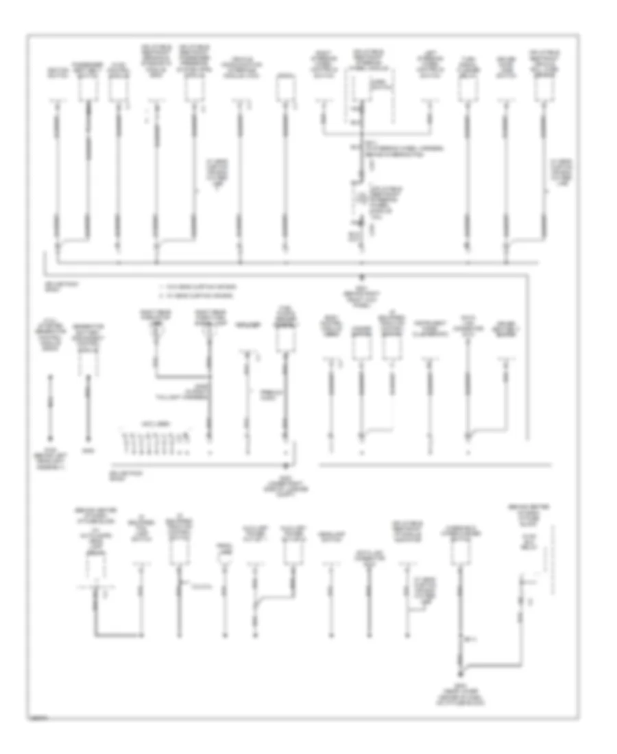 https://portal-diagnostov.com/license.html
Automotive Electricians Portal FZCO
Automotive Electricians Portal FZCO
https://portal-diagnostov.com/license.html
https://portal-diagnostov.com/license.html
Automotive Electricians Portal FZCO
Automotive Electricians Portal FZCOList of elements for Ground Distribution Wiring Diagram (2 of 3) for Saturn Vue Red Line 2007:
- (2.4l) starter generator control module (sgcm)
- (behind center of dash) i/p fuse block
- (if equipped) fog lamp switch
- (if equipped) traction control switch
- (in right taillight harness)
- (not used)
- (w/ autolamps) head lamp relay
- 2.2l/2.4l
- Amplifier
- Auxiliary power outlet 1
- Auxiliary power outlet 2
- Body control module (bcm)
- C277
- C279
- Data link connector (dlc)
- Driver door jamb switch
- Driver seat belt switch
- F c4
- Fuel pump & sender assembly
- G108 (behind left headlight assembly)
- G201 (behind right front kick panel)
- G203 (near lower center of dash, on i/p fuse block)
- G403 (under right side of luggage compt)
- G405
- Generator battery disconnect control module
- Hazard switch
- Headlamp switch
- Horn switch
- Hvac blo relay
- Hvac control module
- Ignition switch
- Inflatable restraint i/p module indicator
- Inflatable restraint passenger presence system (pps) module
- Inflatable restraint sensing & diagnostic module (sdm)
- Inflatable restraint steering wheel module
- Inflatable restraint steering wheel module coil
- Inflatable restraint vehicle roll over sensor
- Instrument panel cluster (ipc)
- Left steering wheel controls
- Nca
- Passenger seat belt switch
- Premium audio
- Prndl lamp
- Radio
- Right rear park/stop lamp
- Right rear park/turn signal lamp
- Right steering wheel controls
- S211 (in steering wheel harness, behind steering pad)
- S213
- S406
- Splice pack sp201
- Splice pack sp403
- Switch
- Turn signal flasher relay
- Vehicle communication interface module (vcim)
- W/ head curtain air bag
- W/ head curtain air bag w/o red line
- W/o head curtain air bag
- Windshield wiper/washer switch
Ground Distribution Wiring Diagram (3 of 3) for Saturn Vue Red Line 2007
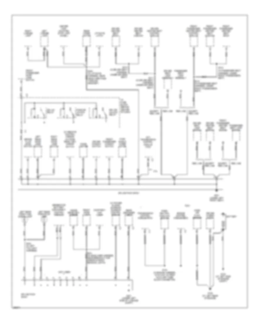 https://portal-diagnostov.com/license.html
Automotive Electricians Portal FZCO
Automotive Electricians Portal FZCO
https://portal-diagnostov.com/license.html
https://portal-diagnostov.com/license.html
Automotive Electricians Portal FZCO
Automotive Electricians Portal FZCOList of elements for Ground Distribution Wiring Diagram (3 of 3) for Saturn Vue Red Line 2007:
- (2.4l)
- (a/t) transmission control module (tcm)
- (in passenger seat harness, under front passenger's seat)
- (not used)
- (w/ power sliding sunroof) sunroof control module
- (w/ remote control mirror) outside rear view mirror switch
- 2.2l
- Battery
- Brake fluid level switch
- Center high mounted stop lamp (chmsl)
- Cigar lighter
- Courtesy/ map lamp
- Dr lck relay
- Driver heated seat back
- Driver heated seat control module
- Driver heated seat cushion
- Driver heated seat switch
- Driver hybrid pump
- Driver seat lamp assembly
- Driver seat lamp switch
- Driver window switch
- Drv dr unlock relay
- E12
- Engine control module (ecm)
- Except red line
- Front dome lamp
- Front passenger door jamb switch
- Front passenger heated seat back
- Front passenger heated seat control module
- Front passenger heated seat cushion
- Front passenger heated seat switch
- Front passenger window switch
- G103 (at left side of engine compt)
- G105 (at left rear of engine)
- G301 (under left front seat)
- G401 (under left side of luggage compt)
- Generator battery disconnect control module
- Headliner pass through grommet)
- I/p fuse block (behind center of dash)
- Inside rearview mirror
- Left license lamp
- Left rear door jamb switch
- Left rear park/stop lamp
- Left rear park/turn signal lamp
- Liftgate latch
- Mass air flow sensor
- Nca
- Park/ neutral position switch
- Pass dr unlock relay
- Passenger seat lamp assembly
- Passenger seat lamp switch
- Rear defogger grid
- Rear wiper motor
- Red line
- Right license lamp
- Right rear door jamb switch
- S104 (in engine harness, 15 cm (5.91 in) from auxiliary fuse block connector)
- S310 (in driver seat harness, under driver's seat)
- S311 (in driver seat harness, under driver's seat)
- S312
- S313 (in passenger seat harness, under front passenger's seat)
- S404 (in left taillight harness)
- Splice pack sp301
- Splice pack sp401
- Transmission control module (tcm)
- Wind- shield wiper motor
HEADLIGHTS
Headlights Wiring Diagram, with Autolamps for Saturn Vue Red Line 2007
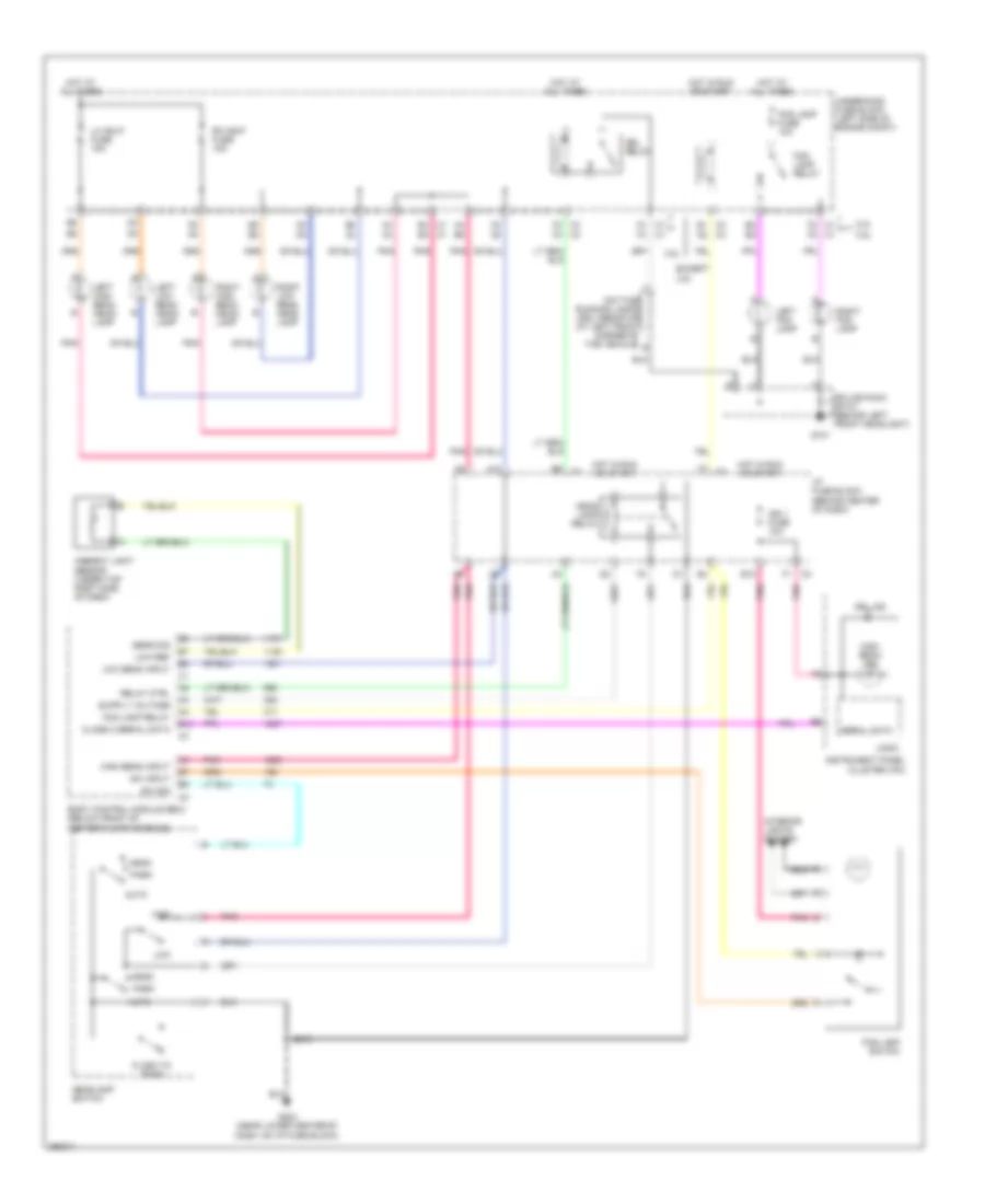 https://portal-diagnostov.com/license.html
Automotive Electricians Portal FZCO
Automotive Electricians Portal FZCO
https://portal-diagnostov.com/license.html
https://portal-diagnostov.com/license.html
Automotive Electricians Portal FZCO
Automotive Electricians Portal FZCOList of elements for Headlights Wiring Diagram, with Autolamps for Saturn Vue Red Line 2007:
- 2.2l
- 3.5l
- A10
- A4 a4
- Ambient light sensor (under top right side of dash)
- Auto
- B10
- Body control module (bcm) (below front of center floor console)
- C1 b4 b4 c1
- C1 f2
- C1 f4
- C3 d2
- C3 e1
- C3 f3
- Class 2 serial data
- D3 d3
- Daytime running lamps (drl) resistor (at left front corner of the vehicle) b
- Drl ind
- Drl relay
- E12
- E3 c4
- E8 e8
- E9 c1
- Except 3.5l
- F1 c3
- F7 c1
- F9 f9
- Flash to pass
- Fog lamp fuse 10a
- Fog lamp relay
- Fog lamp switch
- G101
- G203 (near lower center of dash, on i/p fuse block)
- Head
- Head lamp relay
- Headlamp switch
- High
- High beam ind
- High beam input
- Hot at all times
- Hot in run or start
- I/p fuse block (behind center of dash)
- Ign 1 fuse 10a
- Instrument panel cluster (ipc)
- Interior lights system
- Left fog lamp
- Left high beam head- lamp
- Left low beam head- lamp
- Lh hdlp fuse 15a
- Logic
- Low
- Low beam input
- Low ref
- Park
- Pnk
- Relay ctrl
- Rh hdlp fuse 15a
- Right fog lamp
- Right high beam head- lamp
- Right low beam head- lamp
- S213
- Sens sig
- Serial data
- Splice pack sp101 (behind left front headlight)
- Sw input
- Sw sig
- Underhood fuse block (left side of engine compt)
Headlights Wiring Diagram, without Autolamps for Saturn Vue Red Line 2007
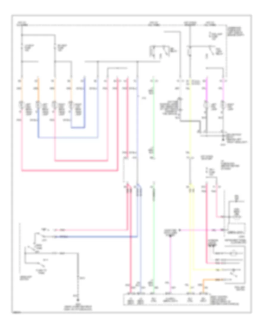 https://portal-diagnostov.com/license.html
Automotive Electricians Portal FZCO
Automotive Electricians Portal FZCO
https://portal-diagnostov.com/license.html
https://portal-diagnostov.com/license.html
Automotive Electricians Portal FZCO
Automotive Electricians Portal FZCOList of elements for Headlights Wiring Diagram, without Autolamps for Saturn Vue Red Line 2007:
- (2.2l) (3.5l)
- 2.2l
- A10
- A6 pnk
- B10
- Body control module (bcm) (below front of center floor console)
- C1 b4
- C1 f2
- C1 f4
- C3 d2
- C3 e1
- C3 f1
- C3 f3
- Class 2 serial data
- Computer data lines system
- Daytime running lamps (drl) resistor (at left front corner of the vehicle) b
- Drl ind
- Drl relay
- E12
- F7 c1
- Flash to pass
- Fog lamp fuse 10a
- Fog lamp relay
- Fog lamp switch
- G101
- G203 (near lower center of dash, on i/p fuse block)
- Head
- Headlamp switch
- Hi beam input
- High
- High beam ind
- Hot at all times
- Hot in run or start
- I/p fuse block (behind center of dash)
- Ign 1 fuse 10a
- Instrument panel cluster (ipc)
- Interior lights system
- Left fog lamp
- Left high beam head- lamp
- Left low beam head- lamp
- Lh hdlp fuse 15a
- Lo beam input
- Logic
- Low
- Off
- Park
- Pnk
- Rh hdlp fuse 15a
- Right fog lamp
- Right high beam head- lamp
- Right low beam head- lamp
- Rly ctrl
- S213
- Serial data
- Splice pack sp101 (behind left front headlight)
- Sw input
- Underhood fuse block (left side of engine compt)
HORN
Horn Wiring Diagram for Saturn Vue Red Line 2007
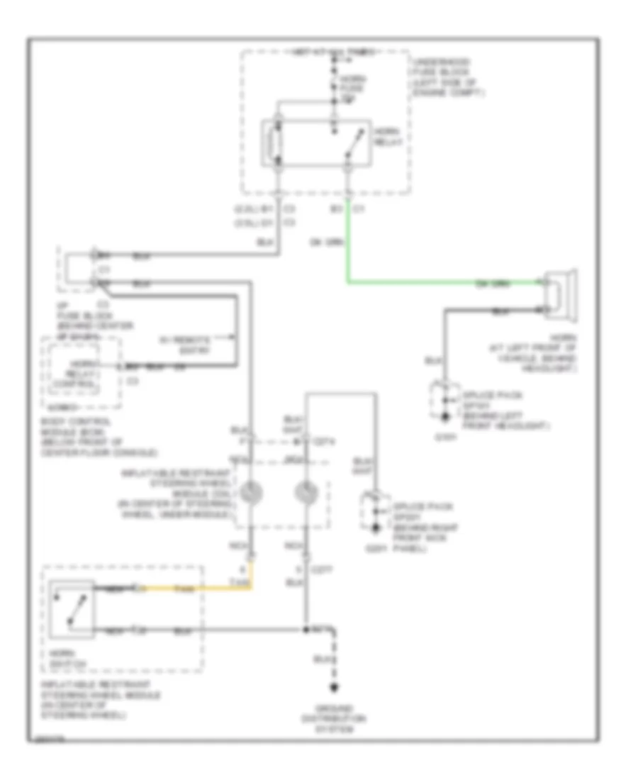 https://portal-diagnostov.com/license.html
Automotive Electricians Portal FZCO
Automotive Electricians Portal FZCO
https://portal-diagnostov.com/license.html
https://portal-diagnostov.com/license.html
Automotive Electricians Portal FZCO
Automotive Electricians Portal FZCOList of elements for Horn Wiring Diagram for Saturn Vue Red Line 2007:
- (2.2l)
- (3.5l)
- B1 c3
- Body control module (bcm) (below front of center floor console)
- C1 b3
- C274
- C277
- C3 d1
- G101
- G201
- Ground distribution system
- Horn (at left front of vehicle, behind headlight)
- Horn fuse 15a
- Horn relay
- Horn relay control
- Horn switch
- Hot at all times
- I/p fuse block (behind center of dash)
- Inflatable restraint steering wheel module (in center of steering wheel)
- Inflatable restraint steering wheel module coil (in center of steering wheel, under module)
- Logic
- Nca
- S211
- Splice pack sp101 (behind left front headlight)
- Splice pack sp201 (behind right front kick panel)
- Tan
- Underhood fuse block (left side of engine compt)
- W/ remote entry
INSTRUMENT CLUSTER
Instrument Cluster Wiring Diagram for Saturn Vue Red Line 2007
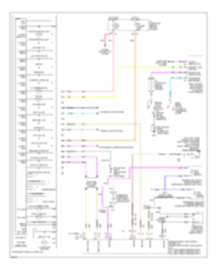 https://portal-diagnostov.com/license.html
Automotive Electricians Portal FZCO
Automotive Electricians Portal FZCO
https://portal-diagnostov.com/license.html
https://portal-diagnostov.com/license.html
Automotive Electricians Portal FZCO
Automotive Electricians Portal FZCOList of elements for Instrument Cluster Wiring Diagram for Saturn Vue Red Line 2007:
- (3.5l: on oil pump housing, on lower right front of engine) (2.2l: on engine block, near oil filter) engine oil pressure switch
- (or 114)
- (or 2759)
- 000000 trip
- 2.2l
- 2.4l
- 2.4l hybrid
- 3.5l
- 3.5l 2.2l
- 3.5l/2.4l hybrid
- Abs ind
- Air bag ind
- B10
- B5 c2
- Battery ind
- Bcm/ cluster fuse 10a
- Body control module (bcm) (below front of center floor console)
- Brake fluid level sw sig
- Brake fluid level switch (on master brake cylinder reservoir)
- Brake ind
- C2 c2
- C3 d4
- Change oil soon ind
- Charge ind
- Class 2 (bcm)
- Class 2 (ebcm)
- Class 2 (ecm)
- Class 2 ser data
- Class 2 serial data
- Computer data lines system
- Coolant temp gauge
- Coolant temp ind
- Drl ind
- Engine control module (ecm) (except 3.5l) powertrain control module (pcm) (3.5l) (2.2l: right side of engine compt) (2.4l: left rear of engine compt) (3.5l: right side of engine compt)
- Engine controls system
- Exterior lights system
- Fuel gauge
- Fuel level sensor
- G201
- G301
- Gnd
- High beam ind
- Hot at all times
- Hot in run or start
- I/p fuse block (behind center of dash)
- I/p fuse block (behind center of dash) c1
- Ign 1 fuse 10a
- Ign 1 volt
- Illumination (4 bulbs)
- Ind con
- Instrument panel cluster (ipc)
- Interior lights system
- Ipc logic
- Km/miles
- Lcd display
- Left turn ind
- Liftgate ajar ind
- Logic
- Low coolant ind
- Low fuel ind
- Low ref
- Low traction ind
- Malfunction ind lamp
- Odometer backlight
- Oil pressure ind
- Park brake switch (at base of park brake lever)
- Park brake switch sig
- Pnk
- Power distribution system
- Primary fuel pump & sender assembly (inside right side of fuel tank)
- Reduced power ind
- Right turn ind
- S401 (in fuel tank jumper harness)
- Seat belt ind
- Secondary fuel pump & sender assembly (inside left side of fuel tank)
- Security ind
- Security led control
- Sen sig
- Ser dt bus+
- Ser dt bus-
- Serial data
- Shift up ind
- Speedometer
- Splice pack sp201 (behind right front kick panel)
- Splice pack sp301 (under left front seat)
- Sw sig
- Tachometer
- Tan
- Traction cntrl off ind
- Underhood fuse block (left side of engine compt)
INTERIOR LIGHTS
Interior Lights Wiring Diagram, with Red Line & Seat Lamps for Saturn Vue Red Line 2007
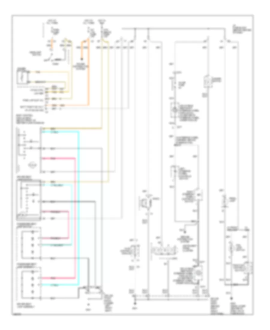 https://portal-diagnostov.com/license.html
Automotive Electricians Portal FZCO
Automotive Electricians Portal FZCO
https://portal-diagnostov.com/license.html
https://portal-diagnostov.com/license.html
Automotive Electricians Portal FZCO
Automotive Electricians Portal FZCOList of elements for Interior Lights Wiring Diagram, with Red Line & Seat Lamps for Saturn Vue Red Line 2007:
- A9 i/p dim ctrl
- B10 park lmp sup vol
- B5 low ref
- Body control module (bcm) (below front of center floor console)
- C274
- C277
- Dimmer switch
- Driver seat lamp assembly
- Driver seat lamp switch
- E i/p lp dim sw sig
- Fog lamp switch
- G201
- G203 (near lower center of dash, on i/p fuse block)
- G301
- Ground distribution system
- H batt positive volt
- Hazard switch
- Head
- Headlamp switch
- Hot at all times
- Hot in run
- Htd seats fuse 10a
- Hvac control module
- I/p fuse block (behind center of dash)
- Inflatable restraint steering wheel module coil (in center of steering wheel, under module)
- Inline fuse 2a
- Instrument panel cluster
- Int lts fuse 10a
- Left steering wheel controls switch
- Logic
- Nca
- Off
- Park
- Park fuse 10a
- Passenger seat lamp assembly
- Passenger seat lamp switch
- Pnk
- Power distribution system
- Prndl lamp
- Radio
- Right steering wheel controls switch
- S211
- S213
- Splice pack sp201 (behind right front kick panel)
- Splice pack sp301 (under left front seat)
- Tan
- Traction control switch
- W/ abs
- W/ front fog lamp
Interior Lights Wiring Diagram, without Red Line & Seat Lamps for Saturn Vue Red Line 2007
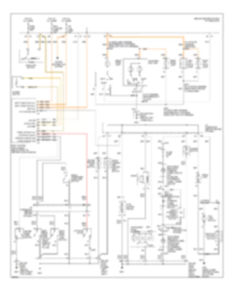 https://portal-diagnostov.com/license.html
Automotive Electricians Portal FZCO
Automotive Electricians Portal FZCO
https://portal-diagnostov.com/license.html
https://portal-diagnostov.com/license.html
Automotive Electricians Portal FZCO
Automotive Electricians Portal FZCOList of elements for Interior Lights Wiring Diagram, without Red Line & Seat Lamps for Saturn Vue Red Line 2007:
- (behind center of dash) i/p fuse block
- (in i/p harness, near breakout to c204) s305
- A sup vol
- A1 sw sig a9 i/p dim ctrl
- A12 pas dr ajar sw sig
- B10
- B10 park lmp sup vol
- B2 lf dr ajar sw sig
- B4 liftgate ajar in
- B5 low ref
- Bcm/ cluster fuse 10a
- Body control module (bcm) (below front of center floor console)
- C1 a6
- C274
- C277
- C3 b6
- Courtesy/ map lamp
- D batt positive volt
- Dimmer switch
- Dome light switch harness) s302
- Door
- Driver door jamb switch
- Driver heated seat switch
- E i/p lp dim sw sig
- E12
- Fog lamp switch
- Front dome lamp
- Front passen- ger heated seat switch
- Front passenger door jamb switch
- G201
- G203 (near lower center of dash, on i/p fuse block)
- G301
- G401
- Ground distribution system
- H batt positive volt
- Hazard switch
- Head
- Headlamp switch
- Hot at all times
- Hvac control module
- I/p fuse block (behind center of dash)
- Inflatable restraint steering wheel module coil (in center of steering wheel, under module)
- Inline fuse 2a
- Instrument panel cluster
- Int lts fuse 10a
- Left lift- gate lamp
- Left rear door jamb switch (near base of left "b" pillar)
- Left steering wheel controls switch
- Liftgate latch
- Logic
- Nca
- Near c402) s402
- Off
- Park
- Park fuse 10a
- Power distribution system
- Prndl lamp
- Radio
- Rear dome lamp
- Right lift- gate lamp
- Right rear door jamb switch
- Right steering wheel controls switch
- S210 (behind steering pad)
- S211
- S213
- S301
- S303 (in headliner harness, near breakout for rear dome light switch harness)
- S400
- S407 (in liftgate harness, near pass-through to headliner)
- Splice pack sp201 (behind right front kick panel)
- Splice pack sp301 (under left front seat)
- Splice pack sp401 (behind left wheelwell)
- Tan
- Traction control switch
- W/ abs
- W/ front fog lamp
POWER DISTRIBUTION
2.2L VIN D
2.2L VIN D, Power Distribution Wiring Diagram (1 of 4) for Saturn Vue Red Line 2007
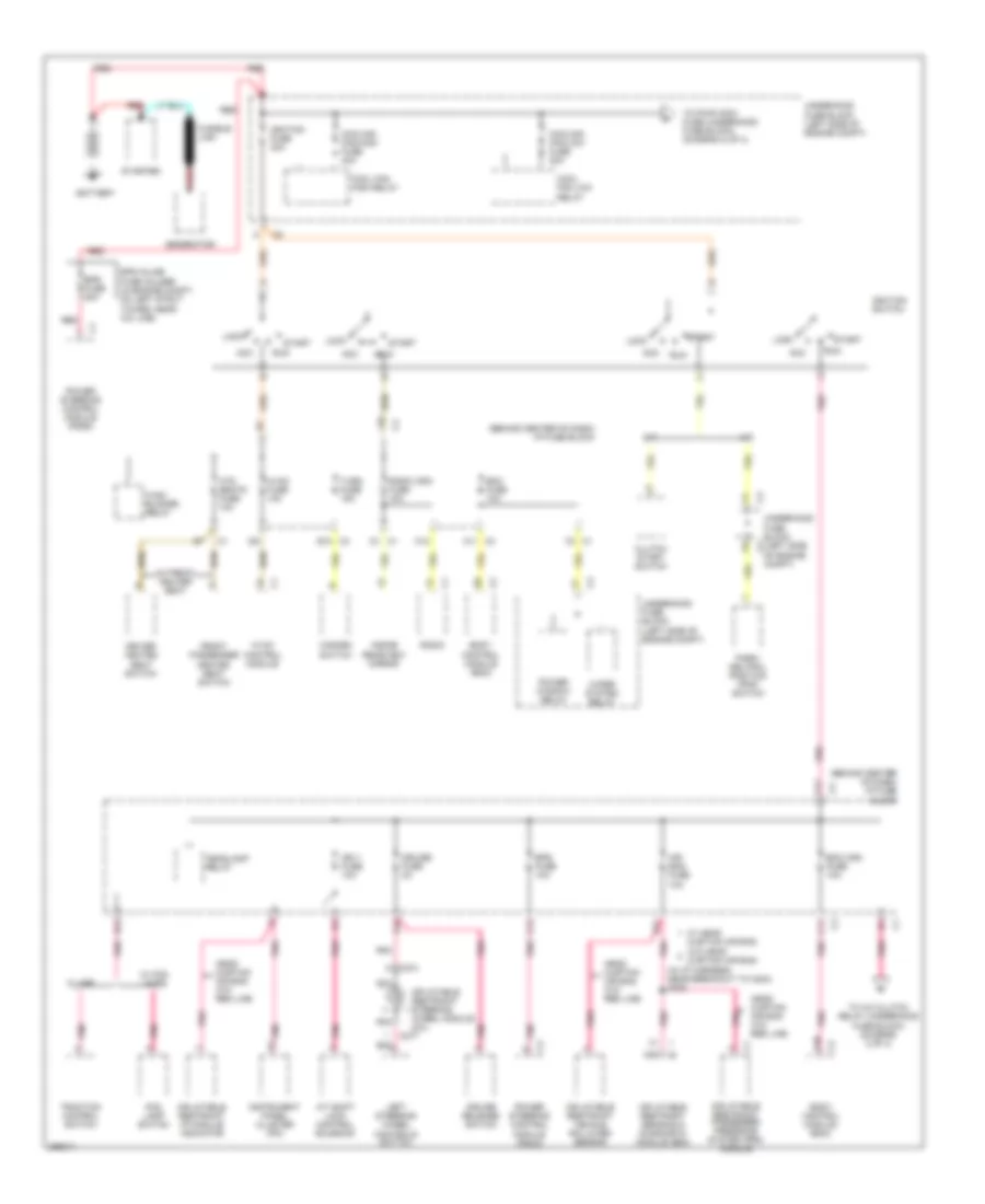 https://portal-diagnostov.com/license.html
Automotive Electricians Portal FZCO
Automotive Electricians Portal FZCO
https://portal-diagnostov.com/license.html
https://portal-diagnostov.com/license.html
Automotive Electricians Portal FZCO
Automotive Electricians Portal FZCOList of elements for 2.2L VIN D, Power Distribution Wiring Diagram (1 of 4) for Saturn Vue Red Line 2007:
- (behind center of dash) i/p fuse block
- (in i/p harness, near breakout to c204) s305
- A/t
- A/t shift lock control solenoid
- A10
- A12
- Acc
- Air bag fuse 10a
- Battery
- Bcm (ign) fuse 10a
- Bcm fuse 10a
- Body control module (bcm)
- C1 f2
- C10
- C11
- C12
- C274 a
- C277
- C3 a11
- C3 e10
- Clutch start switch
- Cool fan high relay
- Cool fan low relay
- Cooling fan-high fuse 40a
- Cooling fan-low fuse 20a
- Cruise fuse 2a
- Cruise release switch
- D1 c1
- Driver heated seat switch
- E11
- E12
- Eps fuse 10a
- Eps fuse 80a
- Eps inline fuse holder (in engine compt, on left strut tower, near a/c line)
- F10
- F12
- Fog lamp switch
- Front passenger heated seat switch
- Fusible link
- Generator
- Hazard switch
- Head curtain air bag w/o red line
- Headlamp relay
- Htd seats fuse 10a
- Hvac blower relay
- Hvac control module
- Hvac fuse 10a
- Ign 1 fuse 10a
- Ignition fuse 30a
- Ignition switch
- Inflatable restraint i/p module indicator
- Inflatable restraint passenger presence system (pps) module
- Inflatable restraint sensing & diagnostic module (sdm)
- Inflatable restraint steering wheel module coil
- Inflatable restraint vehicle rollover sensor
- Inside rearview mirror
- Instrument panel cluster (ipc)
- Left steering wheel controls switch
- Lock
- M/t
- Nca
- Park/ neutral position (pnp) switch
- Pnk
- Pnk a
- Pnk a1
- Power steering control module (pscm)
- Power window relay
- Radio
- Radio (ign) fuse 10a
- Red
- Run
- Start
- Starter
- To a/c clutch relay (underhood fuse block) (diagram 2 of 4)
- To pwr wdw fuse (underhood fuse block) (diagram 2 of 4)
- Traction control switch
- Turn fuse 15a
- Underhood fuse block (left side of engine compt)
- W/ abs
- W/ fog lamps
- W/ front heater seat
- W/ head curtain air bag w/o head curtain air bag
- Wiper system relay
2.2L VIN D, Power Distribution Wiring Diagram (2 of 4) for Saturn Vue Red Line 2007
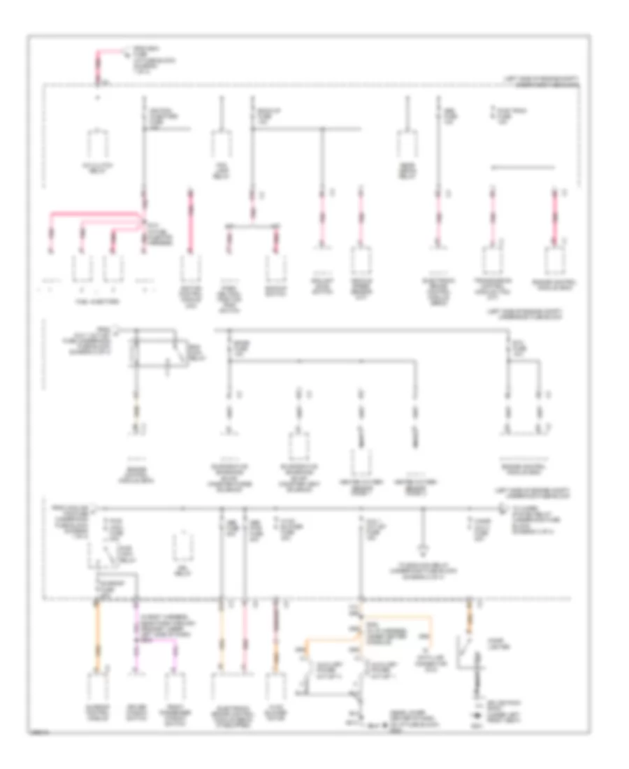 https://portal-diagnostov.com/license.html
Automotive Electricians Portal FZCO
Automotive Electricians Portal FZCO
https://portal-diagnostov.com/license.html
https://portal-diagnostov.com/license.html
Automotive Electricians Portal FZCO
Automotive Electricians Portal FZCOList of elements for 2.2L VIN D, Power Distribution Wiring Diagram (2 of 4) for Saturn Vue Red Line 2007:
- (left side of engine compt) underhood fuse block
- (near lower center of dash, on i/p fuse block) g203
- A/c clutch relay
- A/t
- Abs fuse 10a
- Abs fuse 20a
- Abs pwr fuse 40a
- Aux 1 outlet fuse 15a
- Auxiliary power outlet 1
- Auxiliary power outlet 2
- B12
- Back-up fuse 10a
- Backup switch
- C3 f9
- Cigar lighter
- Cigar/ aux 2 fuse 20a
- Coolant level switch
- D10
- Data link connector (dlc)
- Driver window switch
- Drl relay
- Electronic brake control module (ebcm)
- Electronic brake control module (ebcm) (if equipped)
- Emiss fuse 10a
- Eng main relay
- Engine control module (ecm)
- Etc fuse 15a
- Evaporative emissions (evap) canister purge solenoid
- Evaporative emissions (evap) canister vent solenoid
- F12
- Fog lamp relay
- From bcm fuse (i/p fuse block) (diagram 1 of 4)
- From c aux 1 outlet fuse (underhood fuse block) (diagram 2 of 4)
- From cooling a fan-fuse (underhood fuse block) (diagram 1 of 4)
- Front passenger window switch
- Fuel injectors
- G301
- Heated oxygen sensor (ho2s) 1
- Heated oxygen sensor (ho2s) 2
- Hvac blower fuse 40a
- Hvac blower motor
- Ignition control module (icm)
- Ignition/ injectors fuse 15a
- M/t
- Nca
- Park/ neutral position (pnp) switch
- Pnk
- Pwr train fuse 10a
- Pwr wdw fuse 30a
- Pwr wdw relay
- Rear defog relay
- Red
- S101 (in fuel injector harness)
- S202 (in i/p harness, under center console)
- S204
- S213
- Splice pack sp301 (under left front seat)
- Sunroof control module
- Sunroof fuse 20a
- To eng main relay (underhood fuse block) (diagram 2 of 4)
- To wiper system relay (underhood fuse block) (diagram 3 of 4)
- Transmission control module (tcm) (a/t)
- Vehicle speed sensor (m/t)
2.2L VIN D, Power Distribution Wiring Diagram (3 of 4) for Saturn Vue Red Line 2007
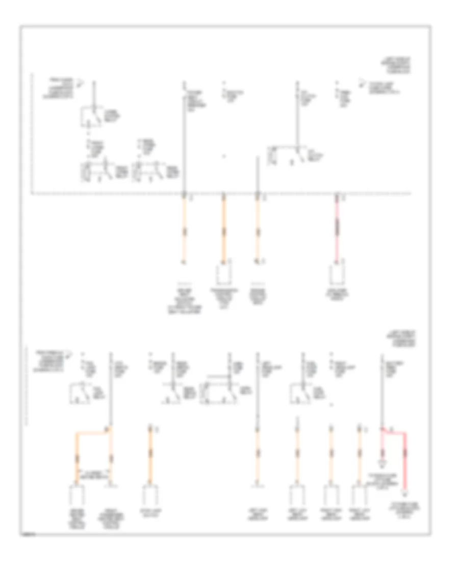 https://portal-diagnostov.com/license.html
Automotive Electricians Portal FZCO
Automotive Electricians Portal FZCO
https://portal-diagnostov.com/license.html
https://portal-diagnostov.com/license.html
Automotive Electricians Portal FZCO
Automotive Electricians Portal FZCOList of elements for 2.2L VIN D, Power Distribution Wiring Diagram (3 of 4) for Saturn Vue Red Line 2007:
- (a/t)
- (left side of engine compt) underhood fuse block
- A/c clutch fuse 10a
- A/c clutch relay
- Amplifier (w/ premium radio)
- Battery feed fuse 40a
- Brake fuse 15a
- D12
- Driver heated seat control module
- Driver seat adjuster switch (w/ front power seat adjuster)
- Ecm/tcm fuse 10a
- Engine control module (ecm)
- Fog lamp fuse 10a
- Fog lamp relay
- From cigar/ aux 2 (underhood fuse block) (diagram 2 of 4)
- From premium audio fuse (underhood fuse block) (diagram 3 of 4)
- Front passenger heated seat control module
- Front wiper fuse 25a
- Front wiper relay
- Fuel pump fuse 10a
- Fuel pump relay
- Horn fuse 15a
- Horn relay
- Htd seats fuse 20a
- Left headlamp fuse 15a
- Left high beam headlamp
- Left low beam headlamp
- Power seat circuit breaker 30a
- Prem aud fuse 20a
- Rear defog fuse 25a
- Rear defog relay
- Rear wiper fuse 15a
- Rear wiper relay
- Red
- Right headlamp fuse 15a
- Right high beam headlamp
- Right low beam headlamp
- Stop lamp switch
- To fog lamp fuse (uhfb) (diagram 3 of 4)
- To park fuse (i/p fuse block) (diagram 4 of 4)
- To radio fuse (i/p fuse block) (diagram 4 of 4)
- Transmission control module (tcm)
- W/ front heated seats
- Wiper system relay
2.2L VIN D, Power Distribution Wiring Diagram (4 of 4) for Saturn Vue Red Line 2007
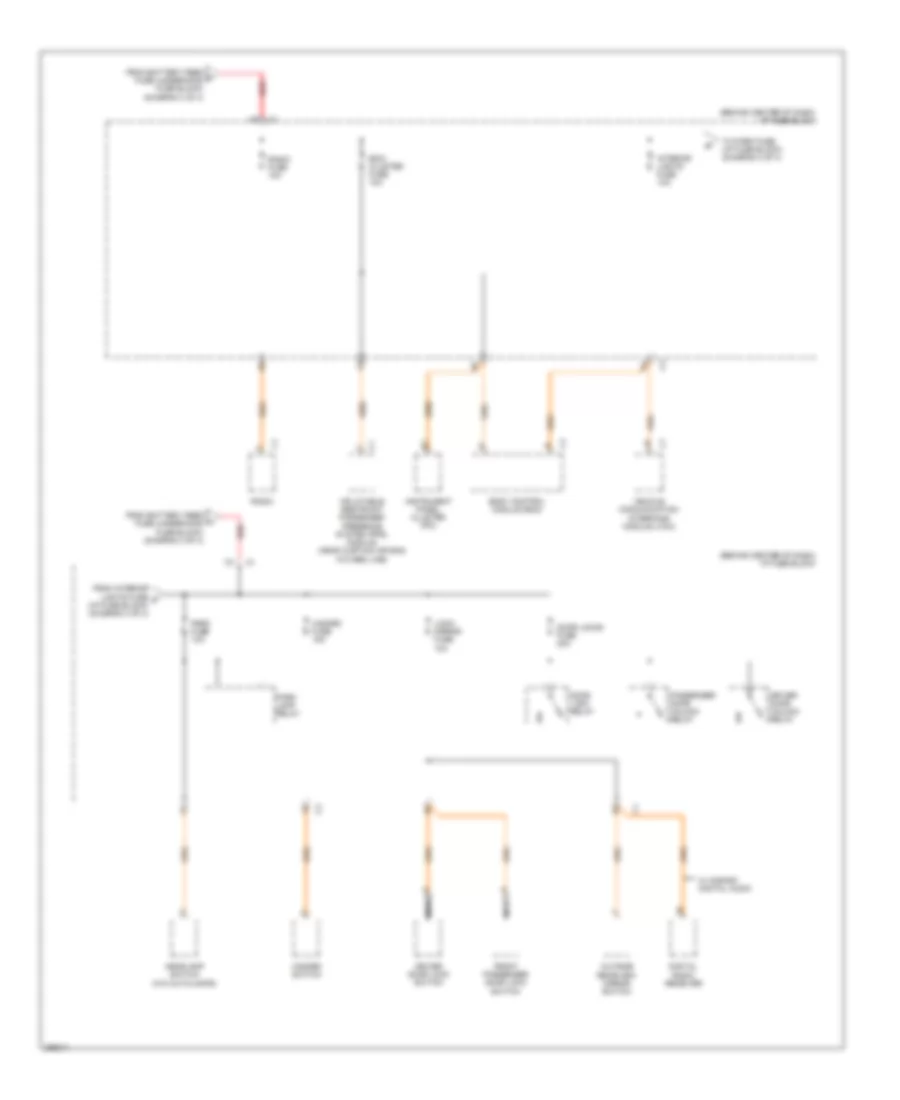 https://portal-diagnostov.com/license.html
Automotive Electricians Portal FZCO
Automotive Electricians Portal FZCO
https://portal-diagnostov.com/license.html
https://portal-diagnostov.com/license.html
Automotive Electricians Portal FZCO
Automotive Electricians Portal FZCOList of elements for 2.2L VIN D, Power Distribution Wiring Diagram (4 of 4) for Saturn Vue Red Line 2007:
- (behind center of dash) i/p fuse block
- Bcm/ cluster fuse 10a
- Body control module (bcm)
- Digital radio receiver
- Door lock relay
- Door locks fuse 20a
- Driver door lock switch
- Driver door unlock relay
- From battery feed f fuse (underhood fuse block) (diagram 3 of 4)
- From battery feed h fuse (underhood fuse block) (diagram 3 of 4)
- From interior lights fuse g (i/p fuse block) (diagram 4 of 4)
- Front passenger door lock switch
- Hazard fuse 15a
- Hazard switch
- Headlamp switch (w/o autolamps)
- Inflatable restraint passenger presence system (pps) module (head curtain air bag w/o red line)
- Instrument panel cluster (ipc)
- Interior lights fuse 10a
- Lock/ mirror fuse 10a
- Nca
- Outside rearview mirror switch
- Park fuse 10a
- Park lamp relay
- Passenger door unlock relay
- Radio
- Radio fuse 10a
- Red
- To park fuse (i/p fuse block) (diagram 4 of 4)
- Vehicle communication interface module (vcim)
- W/ s-band digital audio
2.4L VIN Z
2.4L VIN Z, Power Distribution Wiring Diagram (1 of 4) for Saturn Vue Red Line 2007
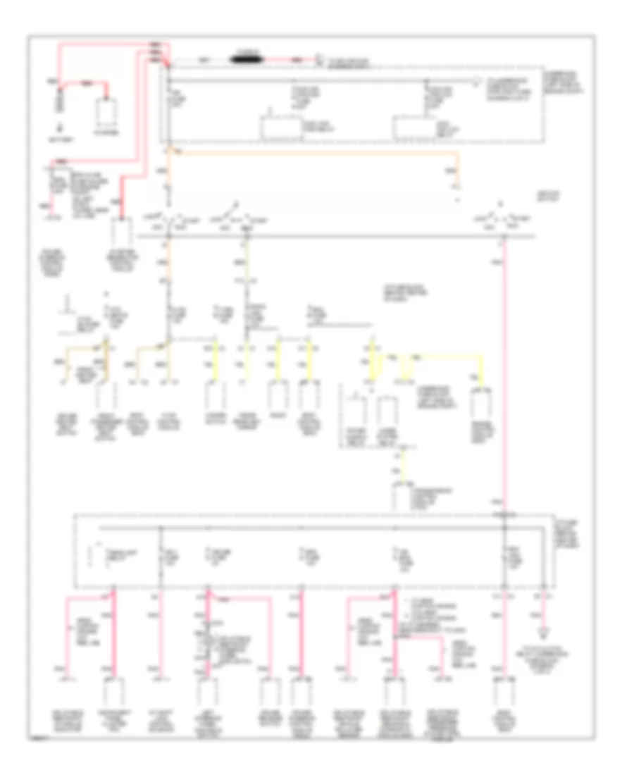 https://portal-diagnostov.com/license.html
Automotive Electricians Portal FZCO
Automotive Electricians Portal FZCO
https://portal-diagnostov.com/license.html
https://portal-diagnostov.com/license.html
Automotive Electricians Portal FZCO
Automotive Electricians Portal FZCOList of elements for 2.4L VIN Z, Power Distribution Wiring Diagram (1 of 4) for Saturn Vue Red Line 2007:
- (in i/p harness, near breakout to c204) s305
- A c274
- A/t shift lock control solenoid
- A10
- A10 c2
- A11 c3
- A12
- A4 c2
- Acc
- Air bag fuse 10a
- B1 c1
- B9 c2
- Battery
- Bcm (ign) fuse 10a
- Bcm fuse 10a
- Body control module (bcm)
- C1 +
- C1 d1
- C10
- C11 c3
- C12
- C277
- C3 f10
- Cool fan high relay
- Cool fan low relay
- Cooling fan-high fuse 40a
- Cooling fan-low fuse 20a
- Cruise fuse 2a
- Cruise release switch
- Driver heated seat switch
- E10 c3
- E11
- Engine control module (ecm)
- Eps fuse 10a
- Eps fuse 80a
- Eps inline fuse holder (in engine compt, on left strut tower, near a/c line)
- F12 c3
- F2 c1
- Front heater seat
- Front passenger heated seat switch
- Fusible link
- Hazard switch
- Head curtain air bag w/o red line
- Headlamp relay
- Htd seats fuse 10a
- Hvac blower relay
- Hvac control module
- Hvac fuse 10a
- I/p fuse block (behind center of dash)
- Ign 1 fuse 10a
- Ign fuse 30a
- Ignition switch
- Inflatable restraint i/p module indicator
- Inflatable restraint passenger presence system (pps) module
- Inflatable restraint sensing & diagnostic module (sdm)
- Inflatable restraint steering wheel module coil
- Inflatable restraint vehicle rollover sensor
- Inside rearview mirror
- Instrument panel cluster (ipc)
- Left steering wheel controls switch
- Lock
- Nca
- Pnk
- Power steering control module (pscm)
- Power window relay
- Radio
- Radio (ign) fuse 10a
- Red
- Run
- Start
- Starter
- Starter generator control module
- To a/c clutch relay (underhood fuse block) (diagram 2 of 4)
- To splice s150 (diagram 2 of 4)
- To underhood fuse block (pwr wdw fuse) (diagram 2 of 4)
- Transmission control module (tcm)
- Turn fuse 15a
- Underhood fuse block (left side of engine compt)
- W/ head curtain air bag w/o head curtain air bag
- Wiper system relay
2.4L VIN Z, Power Distribution Wiring Diagram (2 of 4) for Saturn Vue Red Line 2007
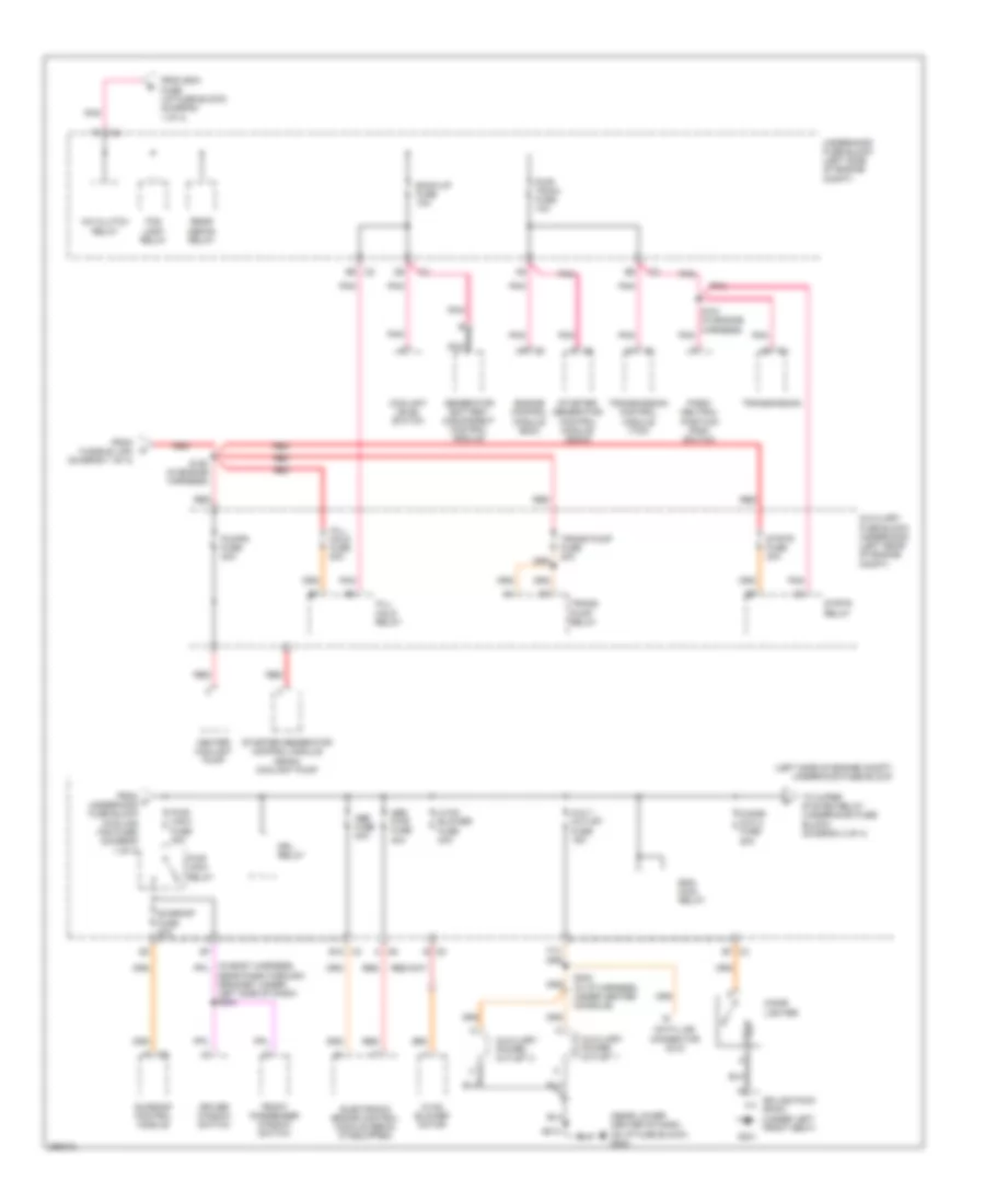 https://portal-diagnostov.com/license.html
Automotive Electricians Portal FZCO
Automotive Electricians Portal FZCO
https://portal-diagnostov.com/license.html
https://portal-diagnostov.com/license.html
Automotive Electricians Portal FZCO
Automotive Electricians Portal FZCOList of elements for 2.4L VIN Z, Power Distribution Wiring Diagram (2 of 4) for Saturn Vue Red Line 2007:
- (left side of engine compt) underhood fuse block
- (near lower center of dash, on i/p fuse block) g203
- A/c clutch relay
- Abs fuse 20a
- Abs pwr fuse 40a
- Aux 1 outlet fuse 15a
- Auxiliary fuse block underhood (left rear of engine compt)
- Auxiliary power outlet 1
- Auxiliary power outlet 2
- B12 c3
- B7 c3
- Back-up fuse 10a
- C2 e9
- C5 b
- C6 a
- Cigar lighter
- Cigar/ aux 2 fuse 20a
- Coolant level switch
- Data link connector (dlc)
- Driver window switch
- Drl relay
- E c1
- Electronic brake control module (ebcm) (if equipped)
- Eng main relay
- Engine control module (ecm)
- F12
- F9 c3
- Fog lamp relay
- From bcm fuse (i/p fuse block) (diagram 1 of 4)
- From c underhood fuse block (cooling fan fuse) (diagram 1 of 4)
- From fusible link (diagram 1 of 4)
- Front passenger window switch
- G301
- Generator battery disconnect control module
- Heater coolant pump
- Hill hold fuse 20a
- Hill hold relay
- Hvac blower fuse 40a
- Hvac blower motor
- Nca
- Near pass-through grommet under left side of dash) s204
- Park/ neutral position (pnp) switch
- Pnk
- Pumps fuse 20a
- Pwr train fuse 10a
- Pwr wdw fuse 30a
- Pwr wdw relay
- Rear defog relay
- Red
- S150 (in engine harness)
- S151 (in engine harness) pnk
- S202 (in i/p harness, under center console)
- S213
- Splice pack sp301 (under left front seat)
- Starter generator control module (sgcm)
- Starter generator control module (sgcm) coolant pump
- Strtr fuse 30a
- Strtr relay
- Sunroof control module
- Sunroof fuse 20a
- To wiper system relay (underhood fuse block) (diagram 3 of 4)
- Trans pump fuse 20a
- Trans pump relay
- Transmission
- Transmission control module (tcm)
- Underhood fuse block (left side of engine compt)
2.4L VIN Z, Power Distribution Wiring Diagram (3 of 4) for Saturn Vue Red Line 2007
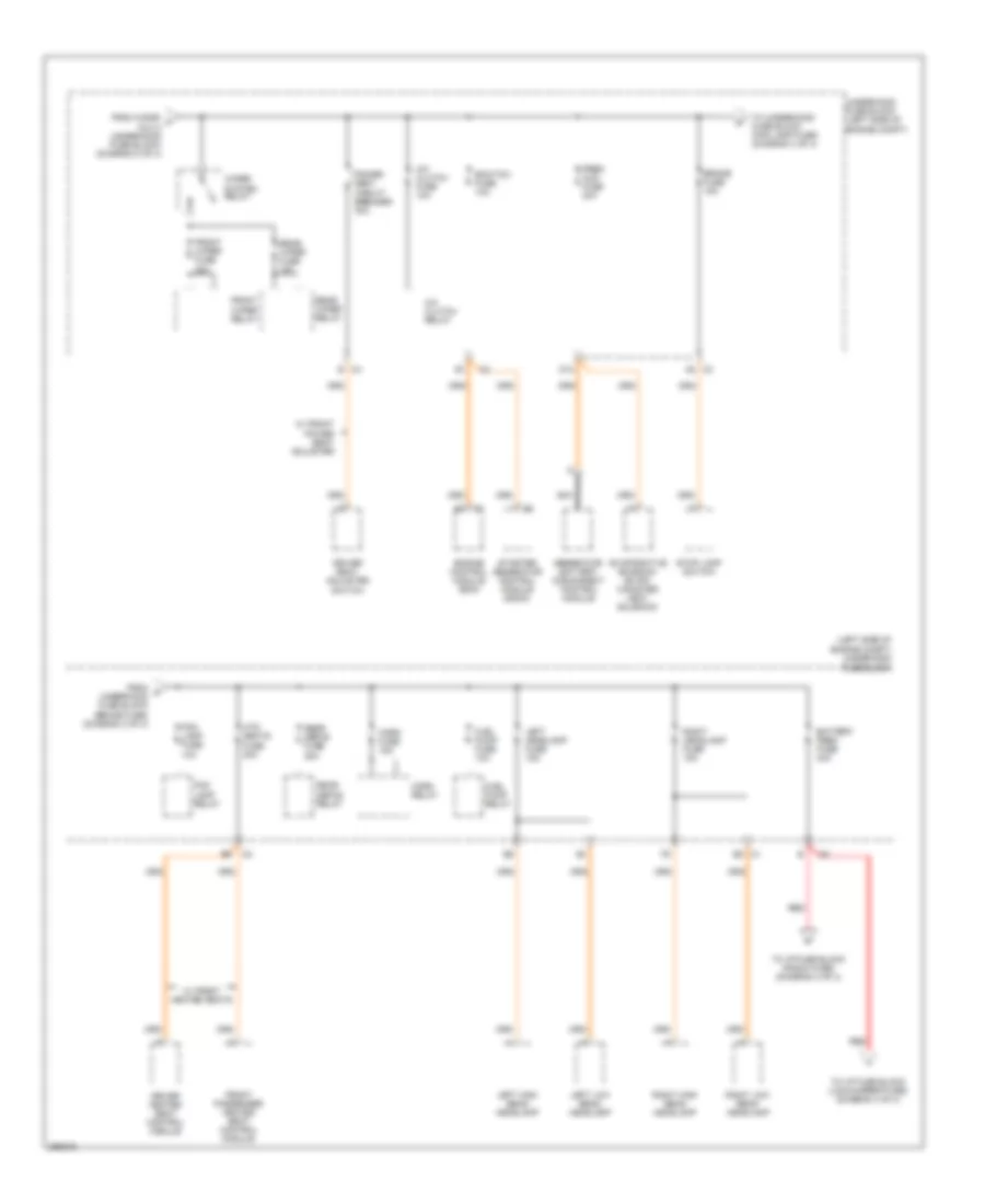 https://portal-diagnostov.com/license.html
Automotive Electricians Portal FZCO
Automotive Electricians Portal FZCO
https://portal-diagnostov.com/license.html
https://portal-diagnostov.com/license.html
Automotive Electricians Portal FZCO
Automotive Electricians Portal FZCOList of elements for 2.4L VIN Z, Power Distribution Wiring Diagram (3 of 4) for Saturn Vue Red Line 2007:
- (left side of engine compt) underhood fuse block
- A/c clutch fuse 10a
- A/c clutch relay
- A8 c3
- Battery feed fuse 40a
- Brake fuse 15a
- C4 b
- D12
- Driver heated seat control module
- Driver seat adjuster switch
- E8 c1
- Ecm/tcm fuse 10a
- Engine control module (ecm)
- Evaporative emission (evap) canister vent solenoid
- Fog lamp fuse 10a
- Fog lamp relay
- From cigar/ f aux 2 (underhood fuse block) (diagram 2 of 4)
- From g underhood fuse block (brake fuse) (diagram 3 of 4)
- Front passenger heated seat control module
- Front wiper fuse 25a
- Front wiper relay
- Fuel pump fuse 10a
- Fuel pump relay
- Generator battery disconnect control module
- Horn fuse 15a
- Horn relay
- Htd seats fuse 20a
- Left headlamp fuse 15a
- Left high beam headlamp
- Left low beam headlamp
- Nca
- Power seat circuit breaker 30a
- Prem aud fuse 20a
- Rear defog fuse 25a
- Rear defog relay
- Rear wiper fuse 15a
- Rear wiper relay
- Red
- Right headlamp fuse 15a
- Right high beam headlamp
- Right low beam headlamp
- Starter generator control module (sgcm)
- Stop lamp switch
- To i/p fuse block (lock/mirror fuse) (diagram 4 of 4)
- To i/p fuse block (radio fuse) (diagram 4 of 4)
- To underhood fuse block (fog lamp fuse) (diagram 3 of 4)
- Underhood fuse block (left side of engine compt)
- W/ front heated seats
- W/ front power seat adjuster
- Wiper system relay
2.4L VIN Z, Power Distribution Wiring Diagram (4 of 4) for Saturn Vue Red Line 2007
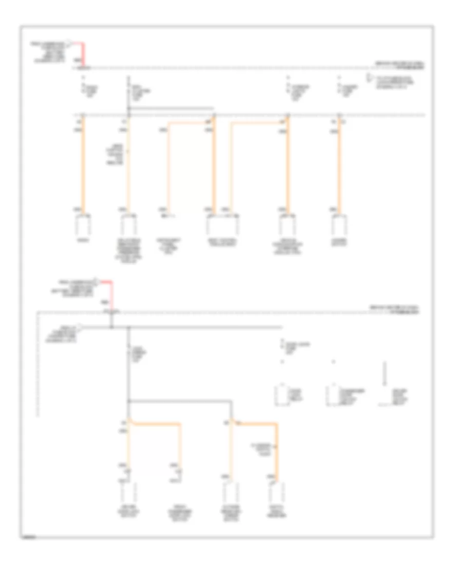 https://portal-diagnostov.com/license.html
Automotive Electricians Portal FZCO
Automotive Electricians Portal FZCO
https://portal-diagnostov.com/license.html
https://portal-diagnostov.com/license.html
Automotive Electricians Portal FZCO
Automotive Electricians Portal FZCOList of elements for 2.4L VIN Z, Power Distribution Wiring Diagram (4 of 4) for Saturn Vue Red Line 2007:
- (behind center of dash) i/p fuse block
- Bcm/ cluster fuse 10a
- Body control module (bcm)
- C1 a5
- Digital radio receiver
- Door lock relay
- Door locks fuse 20a
- Driver door lock switch
- Driver door unlock relay
- From i/p j fuse block (hazard fuse) (diagram 4 of 4)
- From underhood h fuse block (battery feed fuse) (diagram 3 of 4)
- From underhood i fuse block (battery feed fuse) (diagram 3 of 4)
- Front passenger door lock switch
- Hazard fuse 15a
- Hazard switch
- Head curtain air bag w/o redline
- Inflatable restraint passenger presence system (pps) module
- Instrument panel cluster (ipc)
- Interior lights fuse 10a
- Lock/ mirror fuse 10a
- Nca
- Outside rearview mirror switch
- Passenger door unlock relay
- Radio
- Radio fuse 15a
- Red
- To i/p fuse block (lock/mirror fuse) (diagram 4 of 4)
- Vehicle communication interface module (vcim)
- W/ s-band digital audio
3.5L VIN 4
3.5L VIN 4, Power Distribution Wiring Diagram (1 of 4) for Saturn Vue Red Line 2007
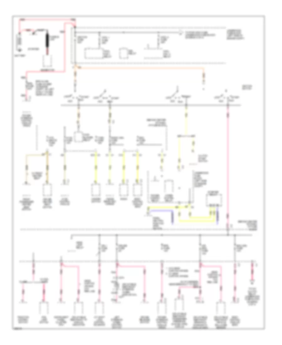 https://portal-diagnostov.com/license.html
Automotive Electricians Portal FZCO
Automotive Electricians Portal FZCO
https://portal-diagnostov.com/license.html
https://portal-diagnostov.com/license.html
Automotive Electricians Portal FZCO
Automotive Electricians Portal FZCOList of elements for 3.5L VIN 4, Power Distribution Wiring Diagram (1 of 4) for Saturn Vue Red Line 2007:
- (behind center of dash) i/p fuse block
- (in i/p harness, near breakout to c204) s305
- A/t
- A/t shift lock control solenoid
- A10
- A12
- Acc
- Air bag fuse 10a
- Battery
- Bcm (ign) fuse 10a
- Bcm fuse 10a
- Body control module (bcm)
- C1 d1
- C1 f2
- C10
- C11
- C12
- C274
- C277
- C3 a11
- C3 e10
- Clutch start switch
- Cool 1 fuse 25a
- Cool 2 fuse 25a
- Cool fan 2 relay
- Cool fan 1 relay
- Cruise fuse 2a
- Cruise release switch
- Curtain air bag w/ head curtain air bag
- Driver heated seat switch
- Drl relay
- E11
- E12
- Eps fuse 10a
- Eps fuse 80a
- Eps inline fuse holder (in engine compt, on left strut tower, near a/c line)
- F10
- F12
- Fog lamp switch
- Front passenger heated seat switch
- Fusible link
- Generator
- Hazard switch
- Head curtain air bag w/o red line
- Head lamp relay
- Htd seats fuse 10a
- Hvac blower relay
- Hvac control module
- Hvac fuse 10a
- Ign 1 fuse 10a
- Ignition fuse 30a
- Ignition switch
- Inflatable restraint i/p module indicator
- Inflatable restraint passenger presence system (pps) module
- Inflatable restraint sensing & diagnostic module (sdm)
- Inflatable restraint steering wheel module coil
- Inflatable restraint vehicle rollover sensor
- Inside rearview mirror
- Instrument panel cluster (ipc)
- Left steering wheel control switch
- Lock
- M/t
- Nca
- Park/ neutral position (pnp) switch
- Pnk
- Pnk a
- Power steering control module (pscm)
- Power window relay
- Radio
- Radio (ign) fuse 10a
- Red
- Run
- Rust
- Start
- Starter
- Starter relay
- To a/c clutch relay (underhood fuse block) (diagram 2 of 4)
- To pwr wdw fuse (underhood fuse block) (diagram 2 of 4)
- Traction control switch
- Turn fuse 15a
- Underhood fuse block (left side of engine compt)
- W/ abs
- W/ fog lamps
- W/ front heater seat
- W/o head
- Wiper system relay
3.5L VIN 4, Power Distribution Wiring Diagram (2 of 4) for Saturn Vue Red Line 2007
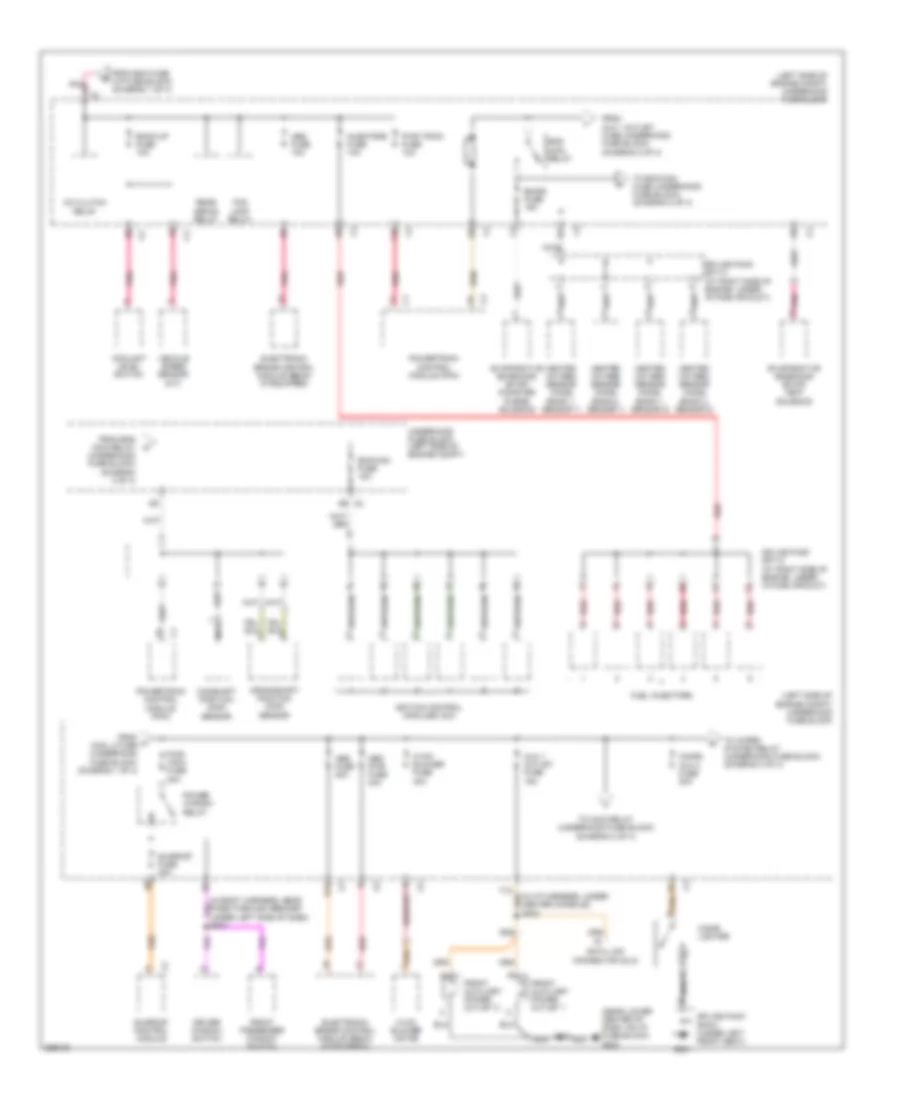 https://portal-diagnostov.com/license.html
Automotive Electricians Portal FZCO
Automotive Electricians Portal FZCO
https://portal-diagnostov.com/license.html
https://portal-diagnostov.com/license.html
Automotive Electricians Portal FZCO
Automotive Electricians Portal FZCOList of elements for 3.5L VIN 4, Power Distribution Wiring Diagram (2 of 4) for Saturn Vue Red Line 2007:
- (in i/p harness, under center console) s202
- (left side of engine compt) underhood fuse block
- (near lower center of dash, on i/p fuse block) g203
- A/c clutch relay
- Abs fuse 10a
- Abs fuse 20a
- Abs pwr fuse 40a
- Aux 1 outlet fuse 15a
- B12
- Back-up fuse 10a
- C3 f9
- Camshaft position (cmp) sensor
- Cigar lighter
- Cigar/ aux 2 fuse 20a
- Coolant level switch
- Crankshaft position (ckp) sensor
- Data link connector (dlc)
- Driver window switch
- E9 c2
- Ecm/cam fuse 15a
- Electronic brake control module (ebcm) (if equipped)
- Emiss fuse 15a
- Eng main relay
- Evaporative emissions (evap) canister purge solenoid
- Evaporative emissions (evap) vent solenoid
- F10
- Fog lamp relay
- From a cool 2 fuse (underhood fuse block) (diagram 1 of 4)
- From aux 1 outlet fuse (underhood fuse block) (diagram 2 of 4)
- From bcm fuse (i/p fuse block) (diagram 1 of 4)
- From eng main relay (underhood fuse block) (diagram 2 of 4)
- Front auxiliary power outlet 1
- Front auxiliary power outlet 2
- Front passenger window switch
- Fuel injectors
- G301
- Heated oxygen sensor (ho2s) (bank 1, sensor 1)
- Heated oxygen sensor (ho2s) (bank 1, sensor 2)
- Heated oxygen sensor (ho2s) (bank 2, sensor 1)
- Heated oxygen sensor (ho2s) (bank 2, sensor 2)
- Hvac blower fuse 40a
- Hvac blower motor
- Ignition control modules (icm)
- Injectors fuse 10a
- Nca
- Pnk
- Power window relay
- Powertrain control module (pcm)
- Pwr train fuse 10a
- Pwr wdw fuse 30a
- Rear defog relay
- Red
- S213
- Splice pack sp113 (at right side of engine, under intake air duct)
- Splice pack sp114 (at right side of engine, under intake air duct)
- Splice pack sp301 (under left front seat)
- Sunroof control module
- Sunroof fuse 20a
- To ecm/cam fuse (underhood fuse block) (diagram 2 of 4)
- To main relay (underhood fuse block) (diagram 2 of 4)
- To wiper system relay (underhood fuse block) (diagram 3 of 4)
- Underhood fuse block (left side of engine compt)
- Vehicle speed sensor (m/t)
3.5L VIN 4, Power Distribution Wiring Diagram (3 of 4) for Saturn Vue Red Line 2007
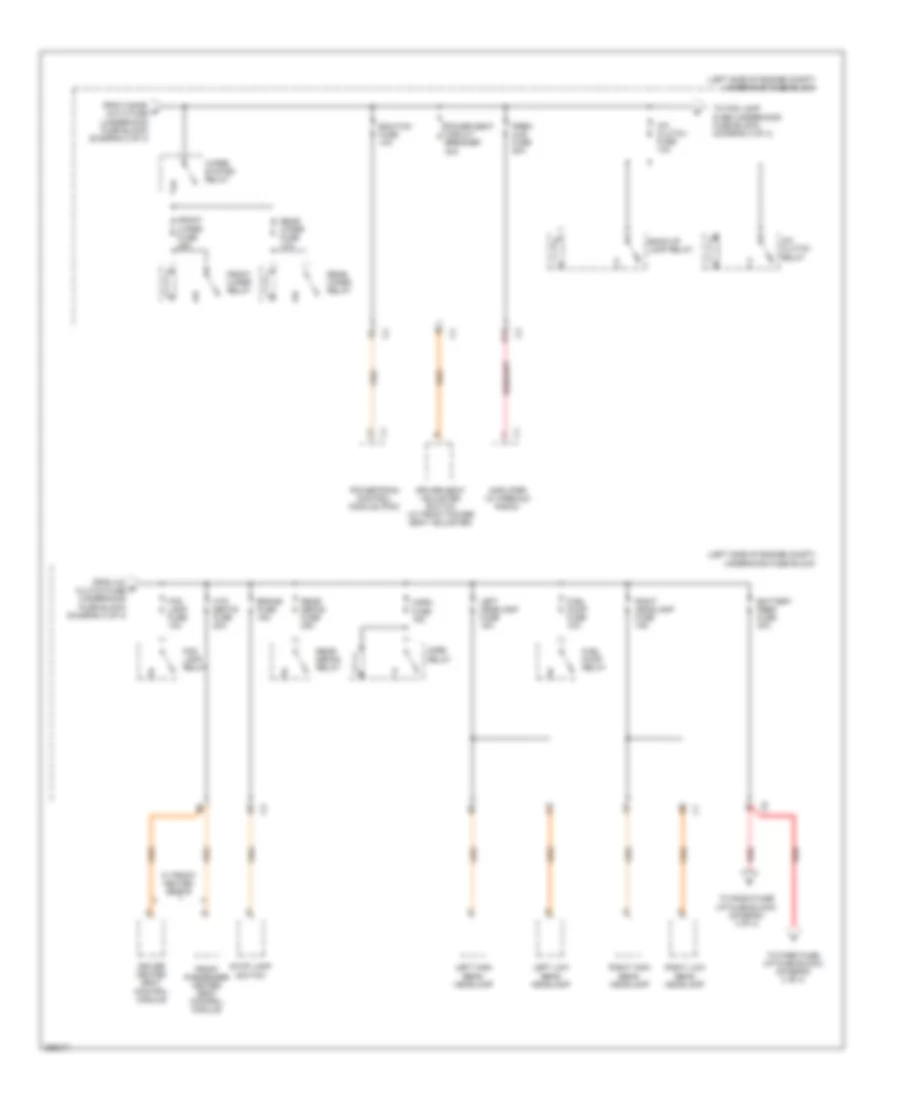 https://portal-diagnostov.com/license.html
Automotive Electricians Portal FZCO
Automotive Electricians Portal FZCO
https://portal-diagnostov.com/license.html
https://portal-diagnostov.com/license.html
Automotive Electricians Portal FZCO
Automotive Electricians Portal FZCOList of elements for 3.5L VIN 4, Power Distribution Wiring Diagram (3 of 4) for Saturn Vue Red Line 2007:
- (left side of engine compt) underhood fuse block
- A/c clutch fuse 10a
- A/c clutch relay
- Amplifier (w/ premium radio)
- Back-up lamp relay
- Battery feed fuse 40a
- Brake fuse 15a
- D12
- Driver heated seat control module
- Driver seat adjuster switch (w/ front power seat adjuster)
- Ecm/tcm fuse 10a
- Fog lamp fuse 10a
- Fog lamp relay
- From a/c e clutch fuse (underhood fuse block) (diagram 3 of 4)
- From cigar/ d aux 2 fuse (underhood fuse block) (diagram 2 of 4)
- Front passenger heated seat control module
- Front wiper fuse 25a
- Front wiper relay
- Fuel pump fuse 10a
- Fuel pump relay
- Horn fuse 15a
- Horn relay
- Htd seats fuse 20a
- Left headlamp fuse 15a
- Left high beam headlamp
- Left low beam headlamp
- Power seat circuit breaker 30a
- Powertrain control module (pcm)
- Prem aud fuse 20a
- Rear defog fuse 25a
- Rear defog relay
- Rear wiper fuse 15a
- Rear wiper relay
- Red
- Right headlamp fuse 15a
- Right high beam headlamp
- Right low beam headlamp
- Stop lamp switch
- To fog lamp fuse (underhood fuse block) (diagram 3 of 4)
- To park fuse (i/p fuse block) (diagram 4 of 4)
- To radio fuse (i/p fuse block) (diagram 4 of 4)
- W/ front heated seats
- Wiper system relay
3.5L VIN 4, Power Distribution Wiring Diagram (4 of 4) for Saturn Vue Red Line 2007
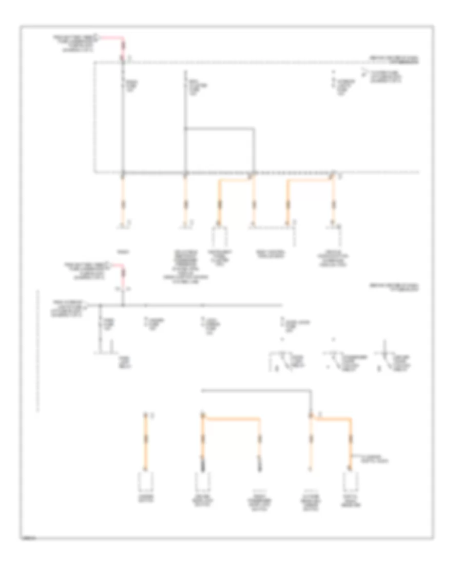 https://portal-diagnostov.com/license.html
Automotive Electricians Portal FZCO
Automotive Electricians Portal FZCO
https://portal-diagnostov.com/license.html
https://portal-diagnostov.com/license.html
Automotive Electricians Portal FZCO
Automotive Electricians Portal FZCOList of elements for 3.5L VIN 4, Power Distribution Wiring Diagram (4 of 4) for Saturn Vue Red Line 2007:
- (behind center of dash) i/p fuse block
- Bcm/ cluster fuse 10a
- Body control module (bcm)
- Digital radio receiver
- Door lock relay
- Door locks fuse 20a
- Driver door lock switch
- Driver door unlock relay
- From battery feed f fuse (underhood fuse block) (diagram 3 of 4)
- From battery feed h fuse (underhood fuse block) (diagram 3 of 4)
- From interior lights fuse g (i/p fuse block) (diagram 4 of 4)
- Front passenger door lock switch
- Hazard fuse 15a
- Hazard switch
- Inflatable restraint passenger presence system (pps) module (head curtain air bag w/o red line)
- Instrument panel cluster (ipc)
- Interior lights fuse 10a
- Lock/ mirror fuse 10a
- Nca
- Outside rearview mirror switch
- Park fuse 10a
- Park lamp relay
- Passenger door unlock relay
- Radio
- Radio fuse 10a
- Red
- To park fuse (i/p fuse block) (diagram 4 of 4)
- Vehicle communication interface module (vcim)
- W/ s-band digital audio
POWER DOOR LOCKS
Power Door Locks Wiring Diagram for Saturn Vue Red Line 2007
 https://portal-diagnostov.com/license.html
Automotive Electricians Portal FZCO
Automotive Electricians Portal FZCO
https://portal-diagnostov.com/license.html
https://portal-diagnostov.com/license.html
Automotive Electricians Portal FZCO
Automotive Electricians Portal FZCOList of elements for Power Door Locks Wiring Diagram for Saturn Vue Red Line 2007:
- (behind center of dash) i/p fuse block
- (behind left front headlight) sp101
- 12v ref
- A12
- B12
- Bcm/ cluster fuse 10a
- Body control module (bcm) (below front of center floor console)
- C10
- C12
- Closed sig
- Computer data lines system
- D10
- Data
- Data bus+
- Data bus-
- Door lock ctrl
- Door unlock ctrl
- Dr lck fuse 20a
- Dr lock relay
- Driver door latch (inside rear of left front door)
- Driver door lock switch
- Driver unlock rly ctrl
- Drv dr unlock relay
- E10
- E12
- F10
- F12
- Front passenger door latch (inside rear of right front door)
- Front passenger door lock switch
- G101
- G301
- Hood ajar switch (integral to hood latch assembly)
- Horn relay ctrl
- Horns system
- Hot at all times
- Ind
- Instrument panel cluster (ipc)
- Int lts fuse 10a
- Interior lights system
- Left rear door latch (inside rear of left rear door)
- Lf dr ajar sw sig
- Liftgate ajar sw sig
- Liftgate latch
- Lock
- Lock/ mirror fuse 10a
- Low ref
- Nca
- Pass dr
- Pass dr ajar sw sig
- Passlock sensor (at top of steering column)
- Power
- Power distribution system
- Return
- Right rear door latch (inside rear of right rear door)
- S400
- Security
- Security ind ctrl
- Sensor signal
- Sp301 (under left front seat)
- Starter generator control module (sgcm) (left front of engine compt)
- Sw lock sig
- Sw sig
- Tan
- Unlock
- Unlock relay
- Unlock sig
- Vbatt
POWER MIRRORS
Electrochromic Mirror Wiring Diagram for Saturn Vue Red Line 2007
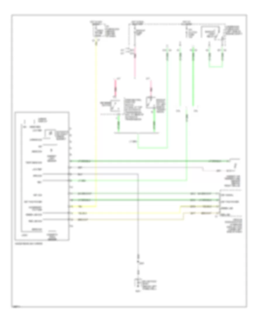 https://portal-diagnostov.com/license.html
Automotive Electricians Portal FZCO
Automotive Electricians Portal FZCO
https://portal-diagnostov.com/license.html
https://portal-diagnostov.com/license.html
Automotive Electricians Portal FZCO
Automotive Electricians Portal FZCOList of elements for Electrochromic Mirror Wiring Diagram for Saturn Vue Red Line 2007:
- 2.2l
- 3.5l
- A/c clutch fuse 10a
- A/t
- A12
- Accessory voltage
- Ambient air temperature sensor (behind front grille)
- Ambient light sensor
- Automatic day/night mirror element
- B10
- B11
- Backup fuse 10a
- Backup lamp relay
- Backup switch (at left side of transm- ission)
- D10 pnk
- G401
- Green led
- Green led sig
- Ground
- Hot at all times
- Hot in acc or run
- Hot in run on start
- I/p fuse block (behind center of dash)
- Ign
- Inside rearview mirror
- Key pad power
- Key sig
- Key signal
- Logic
- Low ref
- M/t
- Magnetic field sensor
- Mess req
- Mirror display
- Mirror sig
- Park/neutral position switch (vt25.e: at top of automatic transmission) (5at: at rear of automatic transmission)
- Pnk
- Radio fuse 10a
- Red led
- Red led sig
- Rev
- Reverse switch
- S301
- Sens sig
- Splice pack sp401 (behind left wheelwell)
- Temp sens sig
- Underhood fuse block (left side of engine compt)
- Vehicle communication interface module (vcim) (under left side of dash)
Power Mirrors Wiring Diagram for Saturn Vue Red Line 2007
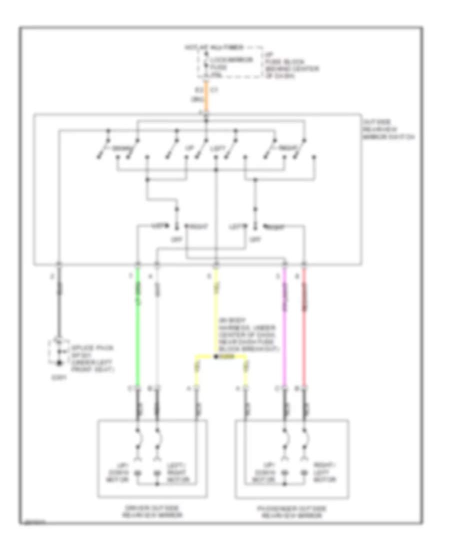 https://portal-diagnostov.com/license.html
Automotive Electricians Portal FZCO
Automotive Electricians Portal FZCO
https://portal-diagnostov.com/license.html
https://portal-diagnostov.com/license.html
Automotive Electricians Portal FZCO
Automotive Electricians Portal FZCOList of elements for Power Mirrors Wiring Diagram for Saturn Vue Red Line 2007:
- (in body harness, under center of dash, near dash fuse block breakout) s209
- C1 e2
- Down
- Driver outside rearview mirror
- G301
- Hot at all times
- I/p fuse block (behind center of dash)
- Left
- Left/ right motor
- Lock/mirror fuse 10a
- Nca
- Off
- Outside rearview mirror switch
- Passenger outside rearview mirror
- Right
- Right/ left motor
- Splice pack sp301 (under left front seat)
- Up/ down motor
POWER SEATS
Driver Seat Wiring Diagram for Saturn Vue Red Line 2007
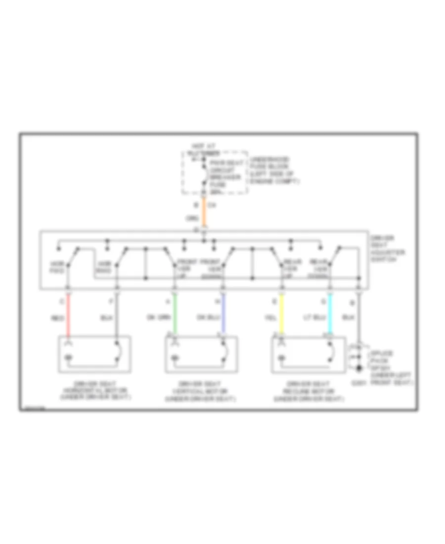 https://portal-diagnostov.com/license.html
Automotive Electricians Portal FZCO
Automotive Electricians Portal FZCO
https://portal-diagnostov.com/license.html
https://portal-diagnostov.com/license.html
Automotive Electricians Portal FZCO
Automotive Electricians Portal FZCOList of elements for Driver Seat Wiring Diagram for Saturn Vue Red Line 2007:
- Driver seat adjuster switch
- Driver seat horizontal motor (under driver seat)
- Driver seat recline motor (under driver seat)
- Driver seat vertical motor (under driver seat)
- Front ver down
- Front ver up
- G301
- Hor fwd
- Hor rwd
- Hot at all times
- Pwr seat circuit breaker fuse 30a
- Rear ver down
- Rear ver up
- Red
- Splice pack sp301 (under left front seat)
- Underhood fuse block (left side of engine compt)
Heated Seats Wiring Diagram for Saturn Vue Red Line 2007
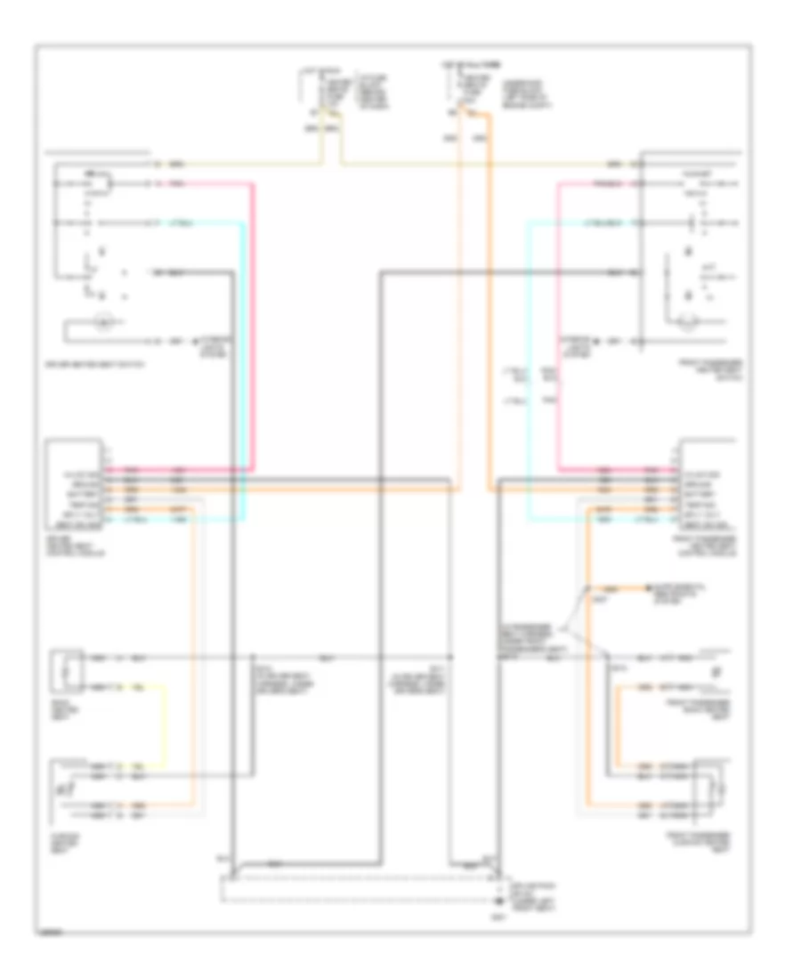 https://portal-diagnostov.com/license.html
Automotive Electricians Portal FZCO
Automotive Electricians Portal FZCO
https://portal-diagnostov.com/license.html
https://portal-diagnostov.com/license.html
Automotive Electricians Portal FZCO
Automotive Electricians Portal FZCOList of elements for Heated Seats Wiring Diagram for Saturn Vue Red Line 2007:
- (in passenger seat harness, under front passenger's seat) s313
- Back heated seat
- Battery
- Cushion heated seat
- Driver heated seat control module
- Driver heated seat switch
- Front passenger back heated seat
- Front passenger cushion heated seat
- Front passenger heated seat control module
- Front passenger heated seat switch
- G301
- Ground
- Heated seats fuse 10a
- Heated seats fuse 20a
- Hi/low sig
- Hot at all times
- Hot in run
- I/p fuse block (behind center of dash)
- Interior lights system
- Nca
- Pnk
- S307
- S310 (in driver seat harness, under driver's seat)
- S311 (in driver seat harness, under driver's seat)
- S312
- Seat sw sig
- Splice pack sp 301 (under left front seat)
- Sply volt
- Temp sig
- Underhood fuse block (left side of engine compt)
POWER TOP/SUNROOF
Power Top/Sunroof Wiring Diagram for Saturn Vue Red Line 2007
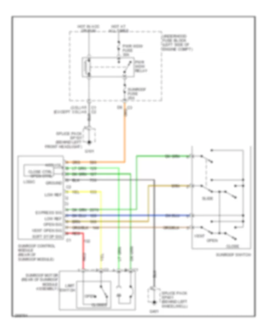 https://portal-diagnostov.com/license.html
Automotive Electricians Portal FZCO
Automotive Electricians Portal FZCO
https://portal-diagnostov.com/license.html
https://portal-diagnostov.com/license.html
Automotive Electricians Portal FZCO
Automotive Electricians Portal FZCOList of elements for Power Top/Sunroof Wiring Diagram for Saturn Vue Red Line 2007:
- (3.5l) (except 3.5l)
- Acc vol
- C1 c2
- Close
- Close ctrl open ctrl
- Closed
- Express sig
- G101
- G401
- Ground
- Hot at all times
- Hot in acc or run
- Limit switch
- Logic
- Low ref
- Open
- Open sig
- Pwr wdw fuse 30a
- Pwr wdw relay
- Red
- Slide
- Soft stop sig
- Splice pack sp101 (behind left front headlight)
- Splice pack sp401 (behind left wheelwell)
- Sunroof control module (rear of sunroof module)
- Sunroof fuse 20a
- Sunroof motor (rear of sunroof module assembly)
- Sunroof switch
- Underhood fuse block (left side of engine compt)
- Vent
- Vent open sig
POWER WINDOWS
Power Windows Wiring Diagram for Saturn Vue Red Line 2007
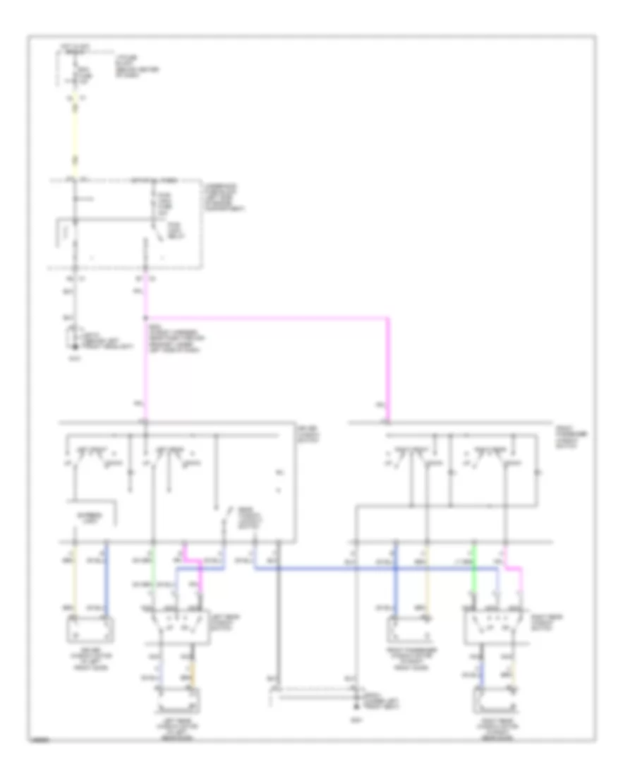 https://portal-diagnostov.com/license.html
Automotive Electricians Portal FZCO
Automotive Electricians Portal FZCO
https://portal-diagnostov.com/license.html
https://portal-diagnostov.com/license.html
Automotive Electricians Portal FZCO
Automotive Electricians Portal FZCOList of elements for Power Windows Wiring Diagram for Saturn Vue Red Line 2007:
- Bcm fuse 10a
- C3 e7
- Down
- Driver window motor (in left front door)
- Driver window switch
- Express logic
- Front passenger window motor (in right front door)
- Front passenger window switch
- G101
- G301
- Hot at all times
- Hot in acc or run
- I/p fuse block (behind center of dash)
- Left front
- Left rear
- Left rear window motor (in left rear door)
- Left rear window switch
- Nca
- Pwr wdw fuse 30a
- Pwr wdw relay
- Rear window lockout switch
- Right front
- Right rear
- Right rear window motor (in right rear door)
- Right rear window switch
- S204 (in body harness, near pass-through grommet under left side of dash)
- Sp101 (behind left front headlight)
- Sp301 (under left front seat)
- Underhood fuse block (left side of engine compartment)
RADIO
Base Radio Wiring Diagram for Saturn Vue Red Line 2007
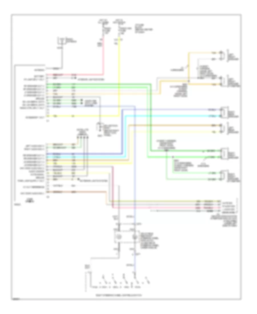 https://portal-diagnostov.com/license.html
Automotive Electricians Portal FZCO
Automotive Electricians Portal FZCO
https://portal-diagnostov.com/license.html
https://portal-diagnostov.com/license.html
Automotive Electricians Portal FZCO
Automotive Electricians Portal FZCOList of elements for Base Radio Wiring Diagram for Saturn Vue Red Line 2007:
- (in body harness, inside left front door) (w/ 6 speakers) s501
- (in body harness, inside right front door) (w/ 6 speakers) s601
- 10 volt reference
- Accessory volt
- Antenna
- Audio common
- Bare
- Battery
- C10
- C274
- C277
- Case ground
- Coax
- Computer data lines system
- Drain wire
- Exterior lights system
- G201
- Gm lan serial data
- Ground
- Hot at all times
- Hot in acc or run
- I/p fuse block (behind center of dash)
- I/p lamp sply volt
- Inflatable restraint steering wheel module coil (in center of steering wheel, under module)
- Interior lights system
- L audio sig
- Left audio sig (+)
- Left front speaker
- Left front speaker (tweeter)
- Left rear speaker
- Lf speaker out (+)
- Lf speaker out (-)
- Lr speaker out (+)
- Lr speaker out (-)
- Mute sig
- Mute signal
- Nav mono audio sig (+)
- Nav mono audio sig (-)
- Nca
- R audio sig
- Radio
- Radio (ign) fuse 10a
- Radio antenna
- Radio ctrl sply volt
- Radio fuse 15a
- Rf speaker out (+)
- Rf speaker out (-)
- Right audio sig (+)
- Right front speaker
- Right front speaker (tweeter)
- Right rear speaker
- Right steering wheel controls switch
- Rr speaker out (+)
- Rr speaker out (-)
- S500 (w/ 6 speakers) (in body harness, inside left front door)
- S600 (w/ 6 speakers) (in body harness, inside right front door)
- Satellite radio circuit
- Splice pack sp201 (behind right front kick panel)
- Tan
- Vehicle communication interface module (vcim) (if equipped) (under left side of dash)
- W/ 6 speakers
Premium Sound Radio Wiring Diagram (1 of 2) for Saturn Vue Red Line 2007
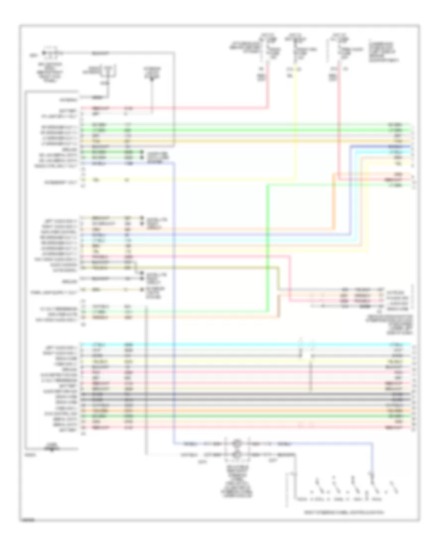 https://portal-diagnostov.com/license.html
Automotive Electricians Portal FZCO
Automotive Electricians Portal FZCO
https://portal-diagnostov.com/license.html
https://portal-diagnostov.com/license.html
Automotive Electricians Portal FZCO
Automotive Electricians Portal FZCOList of elements for Premium Sound Radio Wiring Diagram (1 of 2) for Saturn Vue Red Line 2007:
- 10 volt reference
- 5 volt reference
- Accessory volt
- Amplifier control
- Amplifier mute
- Antenna
- Audio common
- Audio return sig
- Bare
- Battery
- C10
- C274
- C277
- Case ground
- Coax coax
- Computer data lines system
- D12
- Drain wire
- Dvd control sig
- Dvd detection sig
- Exterior lights system
- G201
- Gm lan serial data
- Ground
- Hot at all times
- Hot in acc or run
- I/p fuse block (behind center of dash)
- I/p lamp sply volt
- Inflatable restraint steering wheel module coil (in center of steering wheel, under module)
- Interior lights system
- L audio sig
- Left audio sig (+)
- Left audio sig (-)
- Lf speaker out (+)
- Lf speaker out (-)
- Lr speaker out (+)
- Lr speaker out (-)
- Mute sig
- Mute signal
- Nav mono audio sig (+)
- Nav mono audio sig (-)
- Nca
- Pnk
- Prem audio fuse 20a
- R audio sig
- Radio
- Radio (ign) fuse 10a
- Radio antenna
- Radio ctrl sply volt
- Radio fuse 15a
- Rf speaker out (+)
- Rf speaker out (-)
- Right audio sig (+)
- Right audio sig (-)
- Right steering wheel controls switch
- Rr speaker out (+)
- Rr speaker out (-)
- Satellite radio circuit
- Serial data
- Splice pack sp201 (behind right front kick panel)
- Tan
- Underhood fuse block (left side of engine compartment)
- Vehicle communication interface module (vcim) (if equipped) (under left side of dash)
- Video sig (+)
- Video sig (-)
Premium Sound Radio Wiring Diagram (2 of 2) for Saturn Vue Red Line 2007
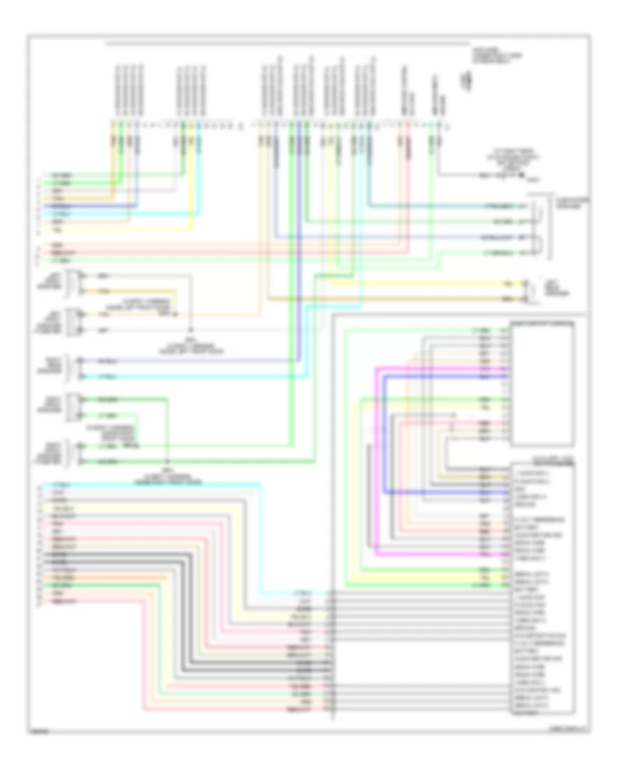 https://portal-diagnostov.com/license.html
Automotive Electricians Portal FZCO
Automotive Electricians Portal FZCO
https://portal-diagnostov.com/license.html
https://portal-diagnostov.com/license.html
Automotive Electricians Portal FZCO
Automotive Electricians Portal FZCOList of elements for Premium Sound Radio Wiring Diagram (2 of 2) for Saturn Vue Red Line 2007:
- (at right rear of storage compt) splice pack sp403
- (in body harness, inside left front door) s500
- (in body harness, inside right front door) s600
- 5 volt reference
- Amplifier (under right side of rear seat)
- Amplifier control
- Amplifier mute
- Audio return sig
- Auxiliary jack switch board
- Bare
- Battery
- Drain wire
- Dvd control sig
- Dvd detection sig
- G403
- Gnd
- Ground
- Ground case
- L audio sig (-)
- L audio sig -
- Left front speaker
- Left front speaker (tweeter)
- Left rear speaker
- Lf speaker out (+)
- Lf speaker out (-)
- Lr speaker out (+)
- Lr speaker out (-)
- Pnk
- R audio sig (-)
- R audio sig -
- Red
- Rf speaker out (+)
- Rf speaker out (-)
- Right front speaker
- Right front speaker (tweeter)
- Right rear speaker
- Rr speaker out (+)
- Rr speaker out (-)
- S501 (in body harness, inside left front door)
- S601 (in body harness, inside right front door)
- Serial data
- Sub spkr coil1 out (+)
- Sub spkr coil1 out (-)
- Sub spkr coil2 out (+)
- Sub spkr coil2 out (-)
- Subwoofer speaker
- Tan
- Video display
- Video display console
- Video sig (+)
- Video sig (-)
Satellite Radio Wiring Diagram for Saturn Vue Red Line 2007
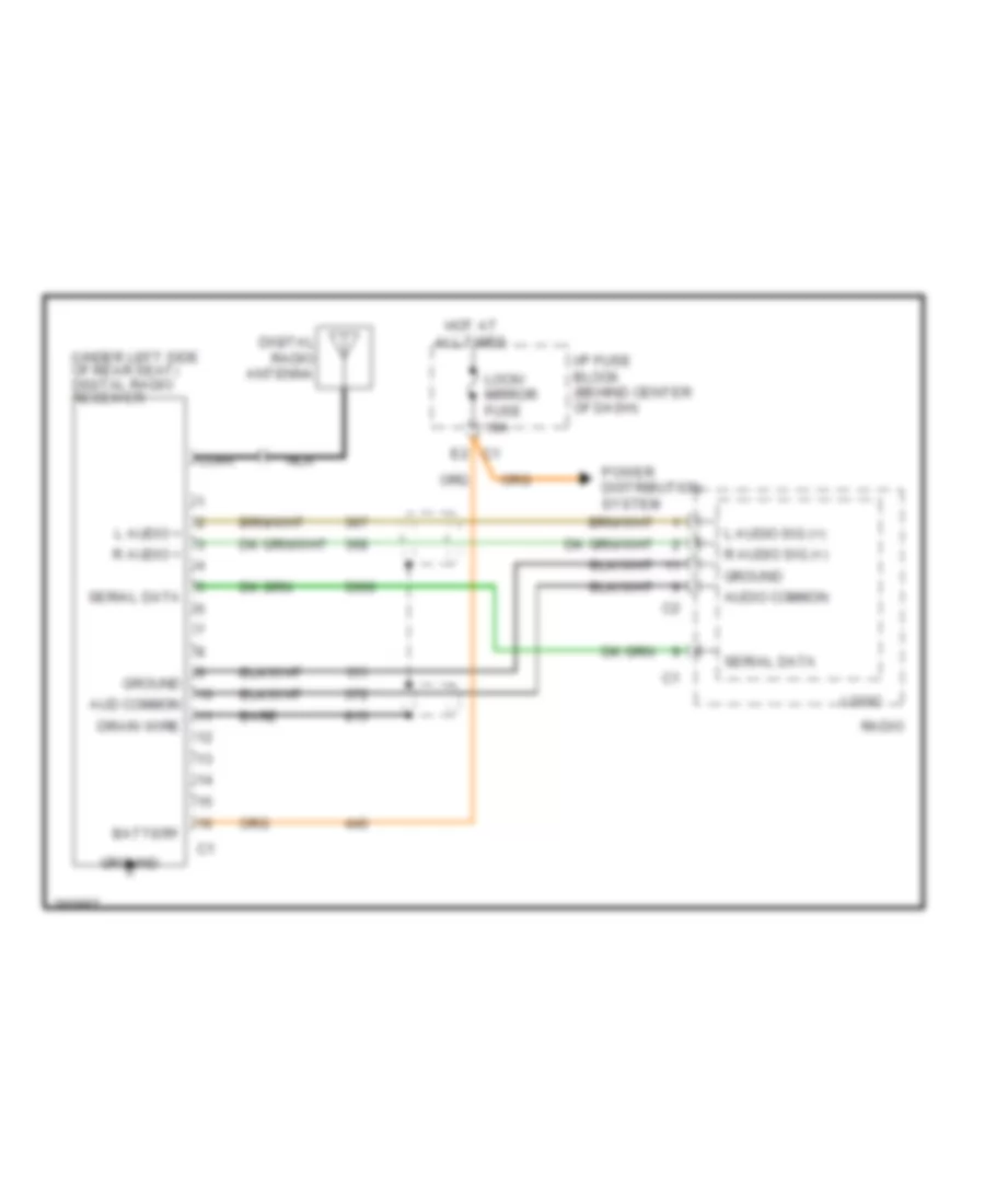 https://portal-diagnostov.com/license.html
Automotive Electricians Portal FZCO
Automotive Electricians Portal FZCO
https://portal-diagnostov.com/license.html
https://portal-diagnostov.com/license.html
Automotive Electricians Portal FZCO
Automotive Electricians Portal FZCOList of elements for Satellite Radio Wiring Diagram for Saturn Vue Red Line 2007:
- (under left side of rear seat) digital radio receiver
- Aud common
- Audio common
- Bare
- Battery
- Coax
- Digital radio antenna
- Drain wire
- E2 c1
- Ground
- Hot at all times
- I/p fuse block (behind center of dash)
- L audio +
- L audio sig (+)
- Lock/ mirror fuse 10a
- Logic
- Nca
- Power distribution system
- R audio +
- R audio sig (+)
- Radio
- Serial data
SHIFT INTERLOCK
2.2L VIN D
2.2L VIN D, Shift Interlock Wiring Diagram for Saturn Vue Red Line 2007
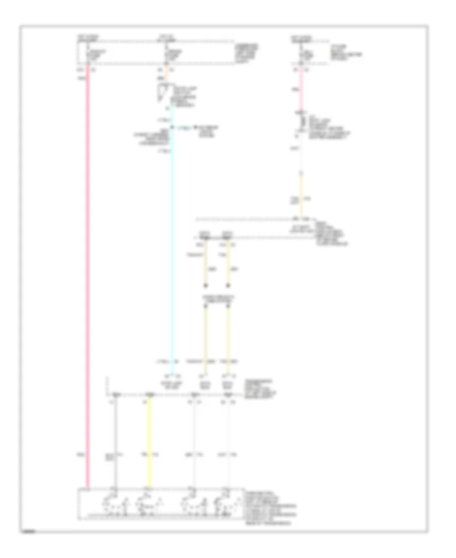 https://portal-diagnostov.com/license.html
Automotive Electricians Portal FZCO
Automotive Electricians Portal FZCO
https://portal-diagnostov.com/license.html
https://portal-diagnostov.com/license.html
Automotive Electricians Portal FZCO
Automotive Electricians Portal FZCOList of elements for 2.2L VIN D, Shift Interlock Wiring Diagram for Saturn Vue Red Line 2007:
- A/t shift lock solenoid (in front center console, at base of shifter assembly)
- A/t shift lock sw sig
- A12
- B12
- Backup fuse 10a
- Body control module (bcm) (below front of center floor console)
- Brake fuse 15a
- Computer data lines system
- D10
- Data bus+
- Data bus-
- Exterior lights system
- Hot at all times
- Hot in run or start
- I/p fuse block (behind center of dash)
- Ign 1 fuse 10a
- Park/neutral position switch (5at: at rear of automatic transmission) (vt25-e: at top of automatic transmission) (4t45-e a/t: on rear of transmission)
- Pnk
- S304 (in body harness, near cross car breakout)
- Stop lamp sw sig
- Stop lamp switch (on brake pedal bracket)
- Tan
- Tr a
- Tr b
- Tr c
- Tr p
- Transmission control module (tcm) (at left side of engine compt)
- Underhood fuse block (left side of engine compt)
3.5L VIN 4
3.5L VIN 4, Shift Interlock Wiring Diagram for Saturn Vue Red Line 2007
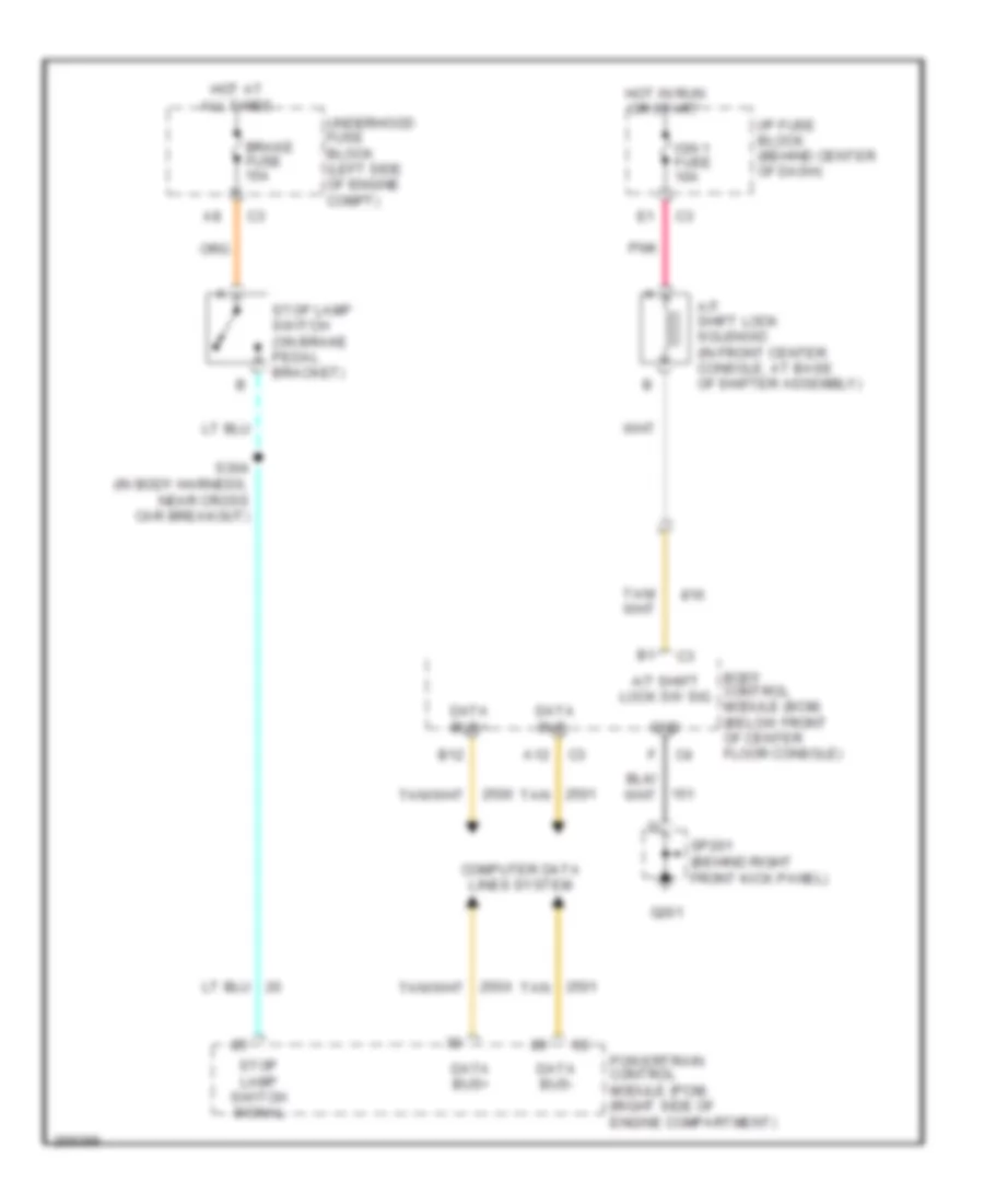 https://portal-diagnostov.com/license.html
Automotive Electricians Portal FZCO
Automotive Electricians Portal FZCO
https://portal-diagnostov.com/license.html
https://portal-diagnostov.com/license.html
Automotive Electricians Portal FZCO
Automotive Electricians Portal FZCOList of elements for 3.5L VIN 4, Shift Interlock Wiring Diagram for Saturn Vue Red Line 2007:
- A/t shift lock solenoid (in front center console, at base of shifter assembly)
- A/t shift lock sw sig
- A12
- B12
- Body control module (bcm) (below front of center floor console)
- Brake fuse 15a
- Computer data lines system
- Data bus+
- Data bus-
- G201
- Gnd
- Hot at all times
- Hot in run or start
- I/p fuse block (behind center of dash)
- Ign 1 fuse 10a
- Pnk
- Powertrain control module (pcm) (right side of engine compartment)
- S304 (in body harness, near cross car breakout)
- Sp201 (behind right front kick panel)
- Stop lamp switch (on brake pedal bracket)
- Stop lamp switch signal
- Tan
- Underhood fuse block (left side of engine compt)
STARTING/CHARGING
Charging Wiring Diagram for Saturn Vue Red Line 2007
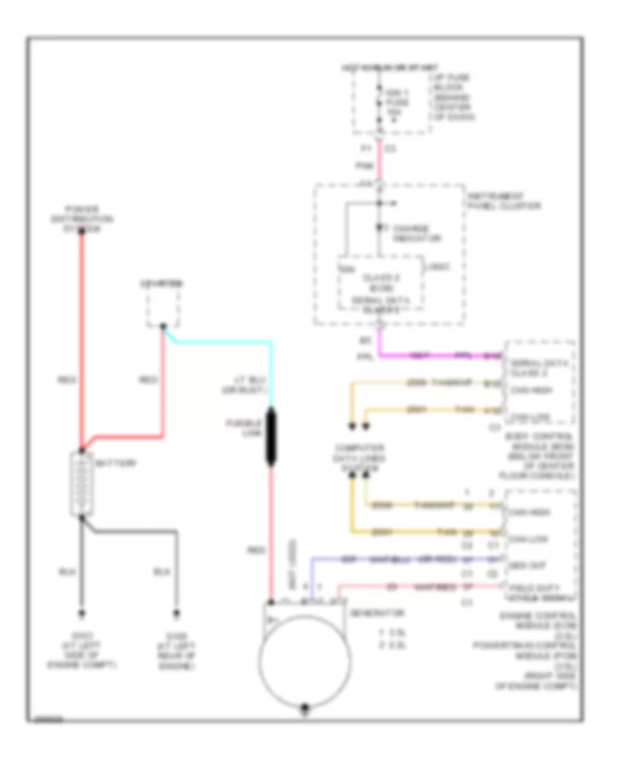 https://portal-diagnostov.com/license.html
Automotive Electricians Portal FZCO
Automotive Electricians Portal FZCO
https://portal-diagnostov.com/license.html
https://portal-diagnostov.com/license.html
Automotive Electricians Portal FZCO
Automotive Electricians Portal FZCOList of elements for Charging Wiring Diagram for Saturn Vue Red Line 2007:
- (not used)
- (or red)
- 2.2l
- 3.5l
- A12
- B10
- B12
- Battery
- Body control module (bcm) (below front of center floor console)
- Can high
- Can low
- Charge indicator
- Class 2 (ecm)
- Computer data lines system
- Engine control module (ecm) (2.2l) powertrain control module (pcm) (3.5l) (right side of engine compt)
- Field duty cycle signal
- Fusible link
- G103 (at left side of engine compt)
- G105 (at left rear of engine)
- Gen out
- Generator
- Hot in run or start
- I/p fuse block (behind center of dash)
- Ign
- Ign 1 fuse 10a
- Instrument panel cluster
- Logic
- Pnk
- Power distribution system
- Red
- Serial data class 2
- Starter
- Tan
2.2L VIN D
2.2L VIN D, Starting Wiring Diagram for Saturn Vue Red Line 2007
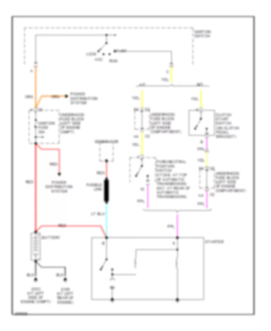 https://portal-diagnostov.com/license.html
Automotive Electricians Portal FZCO
Automotive Electricians Portal FZCO
https://portal-diagnostov.com/license.html
https://portal-diagnostov.com/license.html
Automotive Electricians Portal FZCO
Automotive Electricians Portal FZCOList of elements for 2.2L VIN D, Starting Wiring Diagram for Saturn Vue Red Line 2007:
- A/t
- Acc
- Battery
- Clutch start switch (on clutch pedal bracket)
- Fusible link
- G103 (at left side of engine compt)
- G105 (at left rear of engine)
- Generator
- Ignition fuse 30a
- Ignition switch
- Lock
- M/t
- Park/neutral position switch (vt25-e: at top of automatic transmission) (5at: at rear of automatic transmission)
- Power distribution system
- Red
- Run
- Start
- Starter
- Underhood fuse block (left side of engine c0mpt)
- Underhood fuse block (left side of engine compartment) c2
2.4L VIN Z
2.4L VIN Z, Hybrid Wiring Diagram for Saturn Vue Red Line 2007
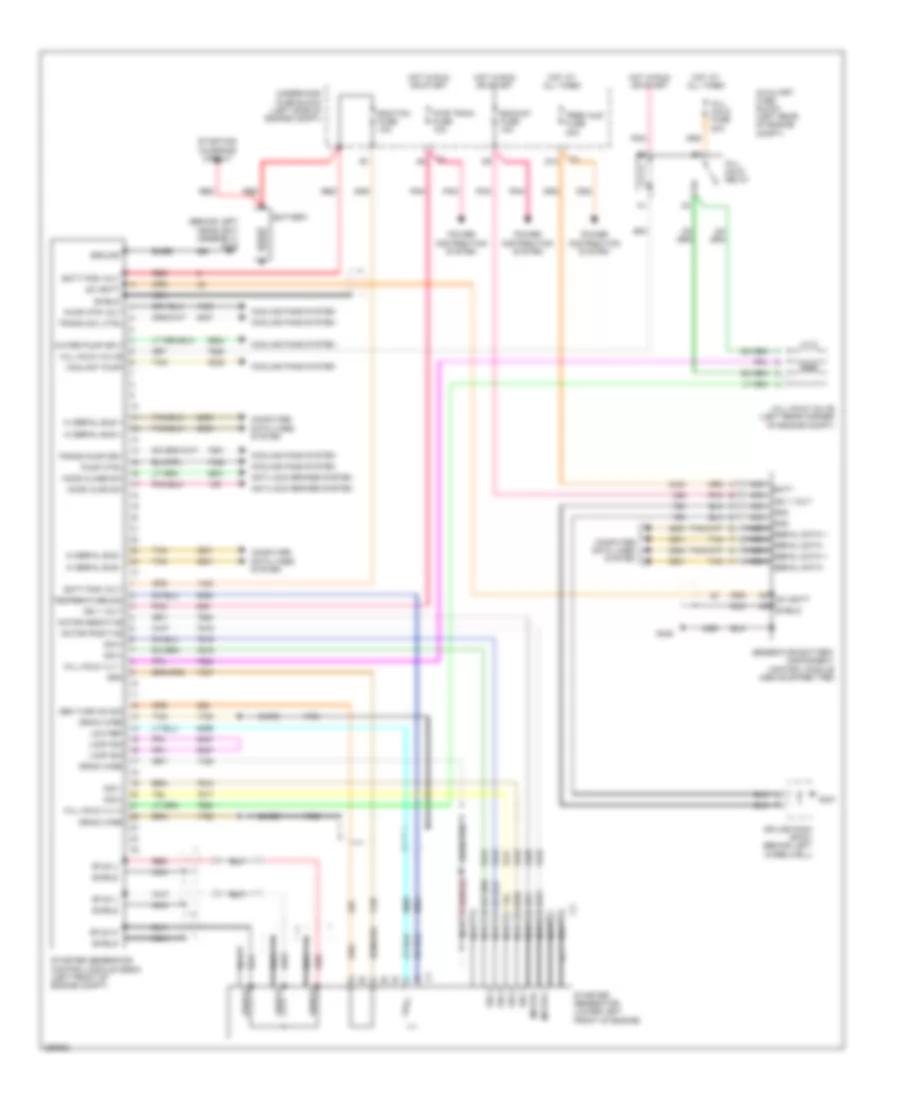 https://portal-diagnostov.com/license.html
Automotive Electricians Portal FZCO
Automotive Electricians Portal FZCO
https://portal-diagnostov.com/license.html
https://portal-diagnostov.com/license.html
Automotive Electricians Portal FZCO
Automotive Electricians Portal FZCOList of elements for 2.4L VIN Z, Hybrid Wiring Diagram for Saturn Vue Red Line 2007:
- (behind left headlight assembly) g108
- 42v batt
- Anti-lock brakes system
- Auxiliary fuse block (left rear of engine compt)
- Backup fuse 10a
- Bare
- Batt
- Batt pos volt
- Battery
- Computer data lines system
- Coolant pump
- Cooling fans system
- D12
- Drain wire
- Ecm/tcm fuse 10a
- G401
- G405
- Gen turn on sig
- Generator battery disconnect control module (above spare tire)
- Gnd
- Ground
- Hi serial bus +
- Hi serial bus -
- Hill hold fuse 20a
- Hill hold relay
- Hill hold valve
- Hill hold valve (left rear corner of engine compt)
- Hill hold vlv 1
- Hill hold vlv 2
- Hood ajar sw
- Hood close sw
- Hot at all times
- Hot in run or start
- Ign 1 volt
- Loop sig
- Low ref
- Motor +
- Motor -
- Motor positive
- Nca
- Pnk
- Power distribution system
- Prem aud fuse 20a
- Pump ctrl
- Pump mtr volt
- Pwr train fuse 10a
- Red
- Red e
- Serial data +
- Serial data -
- Shield
- Sig 1
- Sig 2
- Sig 3
- Sig 4
- Splice pack sp401 (behind left wheelwell)
- Starter generator (lower left front of engine)
- Starter generator control module (sgcm) (left front of engine compt)
- Starting/ charging circuit
- Stud u
- Stud v
- Stud w
- Tan
- Temperature sig
- Trans coil ctrl
- Trans pump drv
- Underhood fuse block (left side of engine compt)
- Water pump sply
2.4L VIN Z, Starting Wiring Diagram for Saturn Vue Red Line 2007
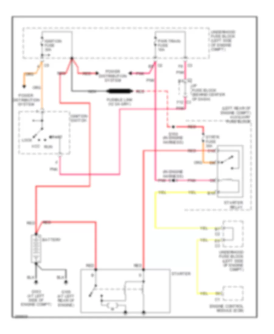 https://portal-diagnostov.com/license.html
Automotive Electricians Portal FZCO
Automotive Electricians Portal FZCO
https://portal-diagnostov.com/license.html
https://portal-diagnostov.com/license.html
Automotive Electricians Portal FZCO
Automotive Electricians Portal FZCOList of elements for 2.4L VIN Z, Starting Wiring Diagram for Saturn Vue Red Line 2007:
- (in engine harness) s151
- (left rear of engine compt) auxiliary fuse block
- Acc
- B10
- Battery
- C10
- Engine control module (ecm)
- F12
- Fusible link
- G103 (at left side of engine compt)
- G105 (at left rear of engine)
- I/p fuse block (behind center of dash)
- Ignition fuse 30a
- Ignition switch
- Lock
- Nca
- Pnk
- Power distribution system
- Pwr train fuse 10a
- Red
- Run
- S150 (in engine harness)
- Start
- Starter
- Starter relay
- Strtr fuse 30a
- Underhood fuse block (left side of engine c0mpt)
3.5L VIN 4
3.5L VIN 4, Starting Wiring Diagram for Saturn Vue Red Line 2007
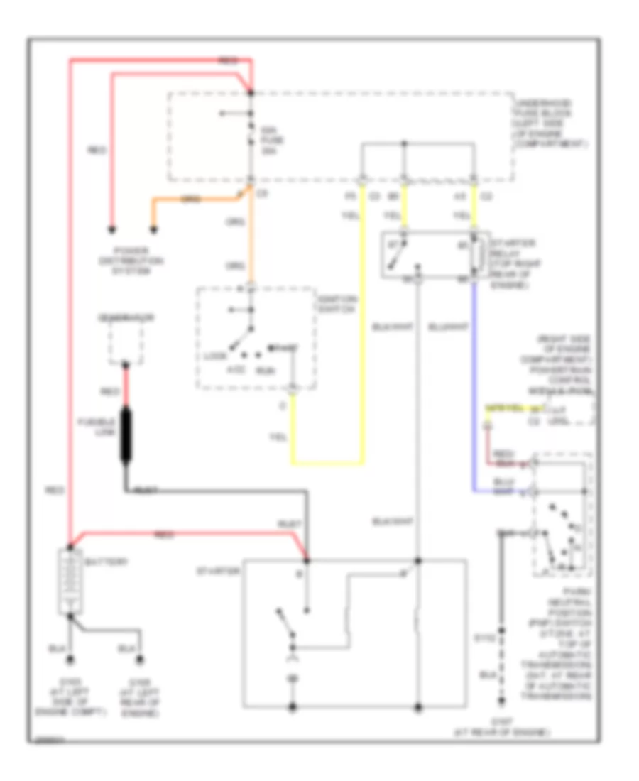 https://portal-diagnostov.com/license.html
Automotive Electricians Portal FZCO
Automotive Electricians Portal FZCO
https://portal-diagnostov.com/license.html
https://portal-diagnostov.com/license.html
Automotive Electricians Portal FZCO
Automotive Electricians Portal FZCOList of elements for 3.5L VIN 4, Starting Wiring Diagram for Saturn Vue Red Line 2007:
- (right side of engine compartment) powertrain control module (pcm)
- A/t sig
- Acc
- Battery
- Fusible link
- G103 (at left side of engine compt)
- G105 (at left rear of engine)
- G107 (at rear of engine)
- Generator
- Ign fuse 30a
- Ignition switch
- Lock
- Park/ neutral position (pnp) switch (vt25-e: at top of automatic transmission) (5at: at rear of automatic transmission)
- Power distribution system
- Red
- Run
- Rust
- S112
- Start
- Starter
- Starter relay (top right rear of engine)
- Underhood fuse block (left side of engine compartment)
SUPPLEMENTAL RESTRAINTS
Supplemental Restraints Wiring Diagram, Hybrid (1 of 2) for Saturn Vue Red Line 2007
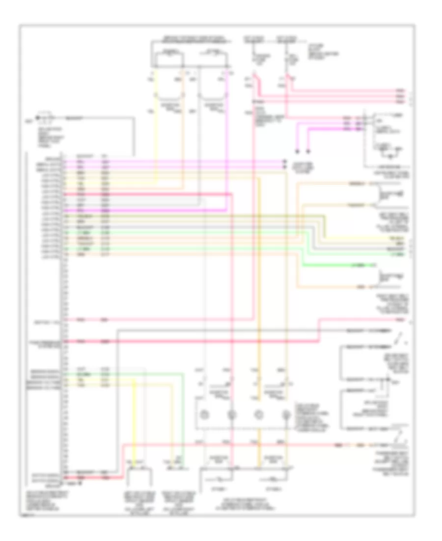 https://portal-diagnostov.com/license.html
Automotive Electricians Portal FZCO
Automotive Electricians Portal FZCO
https://portal-diagnostov.com/license.html
https://portal-diagnostov.com/license.html
Automotive Electricians Portal FZCO
Automotive Electricians Portal FZCOList of elements for Supplemental Restraints Wiring Diagram, Hybrid (1 of 2) for Saturn Vue Red Line 2007:
- (behind top right side of dash) inflatable restraint i/p module
- A2 c3
- Air bag fuse 10a
- Air bag ind
- Class 2 (sdm)
- Class 2 serial data
- Computer data lines system
- Driver seat belt switch (in driver's seat belt buckle)
- E11
- G201
- Ground
- Harness, near breakout to c204)
- High ctrl
- Hot in run or start
- I/p fuse block (behind center of dash)
- Ign
- Ign 1 fuse 10a
- Ignition 1 vol
- Inflatable restraint sensing & diagnostic module (sdm) (under rear of center console)
- Inflatable restraint steering wheel module (in center of steering wheel)
- Inflatable restraint steering wheel module coil (in center of steering wheel, under module)
- Instrument panel cluster (ipc)
- Left inflatable restraint side impact sensor (sis) (on lower left "b" pillar)
- Left seat belt pretensioner (in left "b" pillar, integral to retractor)
- Logic
- Low ctrl
- Nca
- Pass presence system sig
- Passenger seat belt switch (except red line) (in front passenger's seat belt buckle)
- Pnk
- Red
- Right inflatable restraint side impact sensor (sis) (on lower right "b" pillar)
- Right seat belt pretensioner (in right "b" pillar, integral to retractor)
- S305 (in i/p pnk
- Sensing signal
- Sensing voltage
- Serial data
- Shorting bar
- Splice pack sp201 (behind right front kick panel)
- Stage 1
- Stage 2
- Switch signal
- Tan
Supplemental Restraints Wiring Diagram, Hybrid (2 of 2) for Saturn Vue Red Line 2007
 https://portal-diagnostov.com/license.html
Automotive Electricians Portal FZCO
Automotive Electricians Portal FZCO
https://portal-diagnostov.com/license.html
https://portal-diagnostov.com/license.html
Automotive Electricians Portal FZCO
Automotive Electricians Portal FZCOList of elements for Supplemental Restraints Wiring Diagram, Hybrid (2 of 2) for Saturn Vue Red Line 2007:
- B10
- Batt positive vol
- Battery positive vol
- Bcm/ cluster fuse 10a
- G201
- G203 (near lower center of dash, on i/p fuse block)
- Ground
- Hot at all times
- I/p fuse block (behind center of dash)
- Ign 1 vol
- Ign 1 voltage
- Ignition 1 voltage
- Ind ctrl
- Inflatable restraint i/p module indicator (behind top right side of dash)
- Inflatable restraint passenger presence system (pps) module (under front passenger's seat)
- Inflatable restraint passenger presence system (pps) sensor (in passenger seat cushion)
- Inflatable restraint vehicle rollover sensor (asf) (except red line) (under center console, near sdm)
- Left inflatable restraint roof rail module (behind headliner, above driver)
- Logic
- Nca
- Off ind
- On ind
- Pass pre system sig
- Passenger air bag ind
- Pnk
- Position signals
- Power seats system
- Red
- Right inflatable restraint roof rail module (behind headliner, above front passenger)
- S213
- S306 (except red line) (in i/p harness, in breakout to sdm)
- Sensor signal
- Shorting bar
- Splice pack sp201 (behind right front kick panel)
Supplemental Restraints Wiring Diagram, with Head Air Bag (1 of 2) for Saturn Vue Red Line 2007
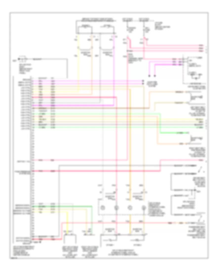 https://portal-diagnostov.com/license.html
Automotive Electricians Portal FZCO
Automotive Electricians Portal FZCO
https://portal-diagnostov.com/license.html
https://portal-diagnostov.com/license.html
Automotive Electricians Portal FZCO
Automotive Electricians Portal FZCOList of elements for Supplemental Restraints Wiring Diagram, with Head Air Bag (1 of 2) for Saturn Vue Red Line 2007:
- (behind top right side of dash) inflatable restraint i/p module
- A2 c3
- Air bag fuse 10a
- Air bag ind
- Class 2 (sdm)
- Class 2 serial data
- Computer data lines system
- Driver seat belt switch (in driver's seat belt buckle)
- E11
- G201
- Ground
- Harness, near breakout to c204)
- High ctrl
- Hot in run or start
- I/p fuse block (behind center of dash)
- Ign
- Ign 1 fuse 10a
- Ignition 1 vol
- Inflatable restraint sensing & diagnostic module (sdm) (under rear of center console)
- Inflatable restraint steering wheel module (in center of steering wheel)
- Inflatable restraint steering wheel module coil (in center of steering wheel, under module)
- Instrument panel cluster (ipc)
- Left inflatable restraint side impact sensor (sis) (on lower left "b" pillar)
- Left seat belt pretensioner (in left "b" pillar, integral to retractor)
- Logic
- Low ctrl
- Nca
- Pass presence system sig
- Passenger seat belt switch (except red line) (in front passenger's seat belt buckle)
- Pnk
- Red
- Right inflatable restraint side impact sensor (sis) (on lower right "b" pillar)
- Right seat belt pretensioner (in right "b" pillar, integral to retractor)
- S305 (in i/p pnk
- Sensing signal
- Sensing voltage
- Serial data
- Shorting bar
- Splice pack sp201 (behind right front kick panel)
- Stage 1
- Stage 2
- Switch signal
- Tan
Supplemental Restraints Wiring Diagram, with Head Air Bag (2 of 2) for Saturn Vue Red Line 2007
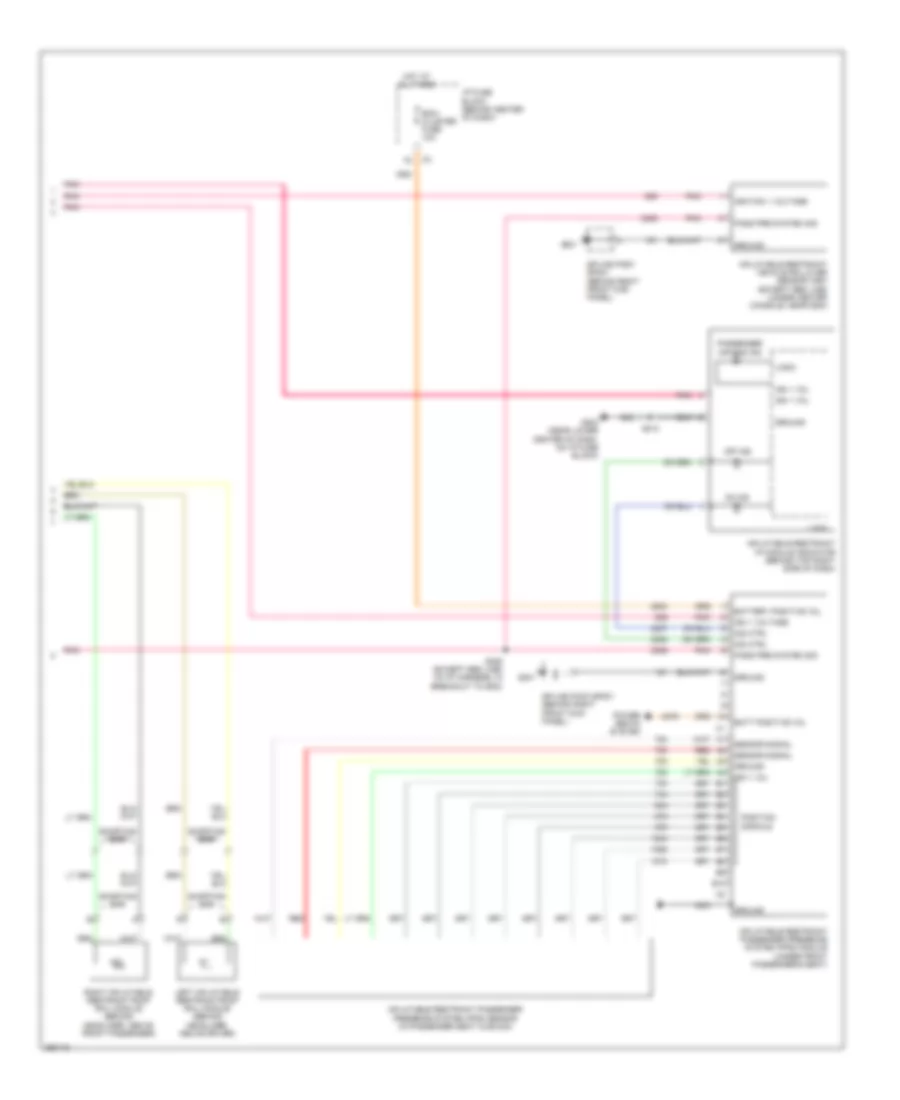 https://portal-diagnostov.com/license.html
Automotive Electricians Portal FZCO
Automotive Electricians Portal FZCO
https://portal-diagnostov.com/license.html
https://portal-diagnostov.com/license.html
Automotive Electricians Portal FZCO
Automotive Electricians Portal FZCOList of elements for Supplemental Restraints Wiring Diagram, with Head Air Bag (2 of 2) for Saturn Vue Red Line 2007:
- B10
- Batt positive vol
- Battery positive vol
- Bcm/ cluster fuse 10a
- G201
- G203 (near lower center of dash, on i/p fuse block)
- Ground
- Hot at all times
- I/p fuse block (behind center of dash)
- Ign 1 vol
- Ign 1 voltage
- Ignition 1 voltage
- Ind ctrl
- Inflatable restraint i/p module indicator (behind top right side of dash)
- Inflatable restraint passenger presence system (pps) module (under front passenger's seat)
- Inflatable restraint passenger presence system (pps) sensor (in passenger seat cushion)
- Inflatable restraint vehicle rollover sensor (asf) (except red line) (under center console, near sdm)
- Left inflatable restraint roof rail module (behind headliner, above driver)
- Logic
- Nca
- Off ind
- On ind
- Pass pre system sig
- Passenger air bag ind
- Pnk
- Position signals
- Power seats system
- Red
- Right inflatable restraint roof rail module (behind headliner, above front passenger)
- S213
- S306 (except red line) (in i/p harness, in breakout to sdm)
- Sensor signal
- Shorting bar
- Splice pack sp201 (behind right front kick panel)
Supplemental Restraints Wiring Diagram, without Head Air Bag (1 of 2) for Saturn Vue Red Line 2007
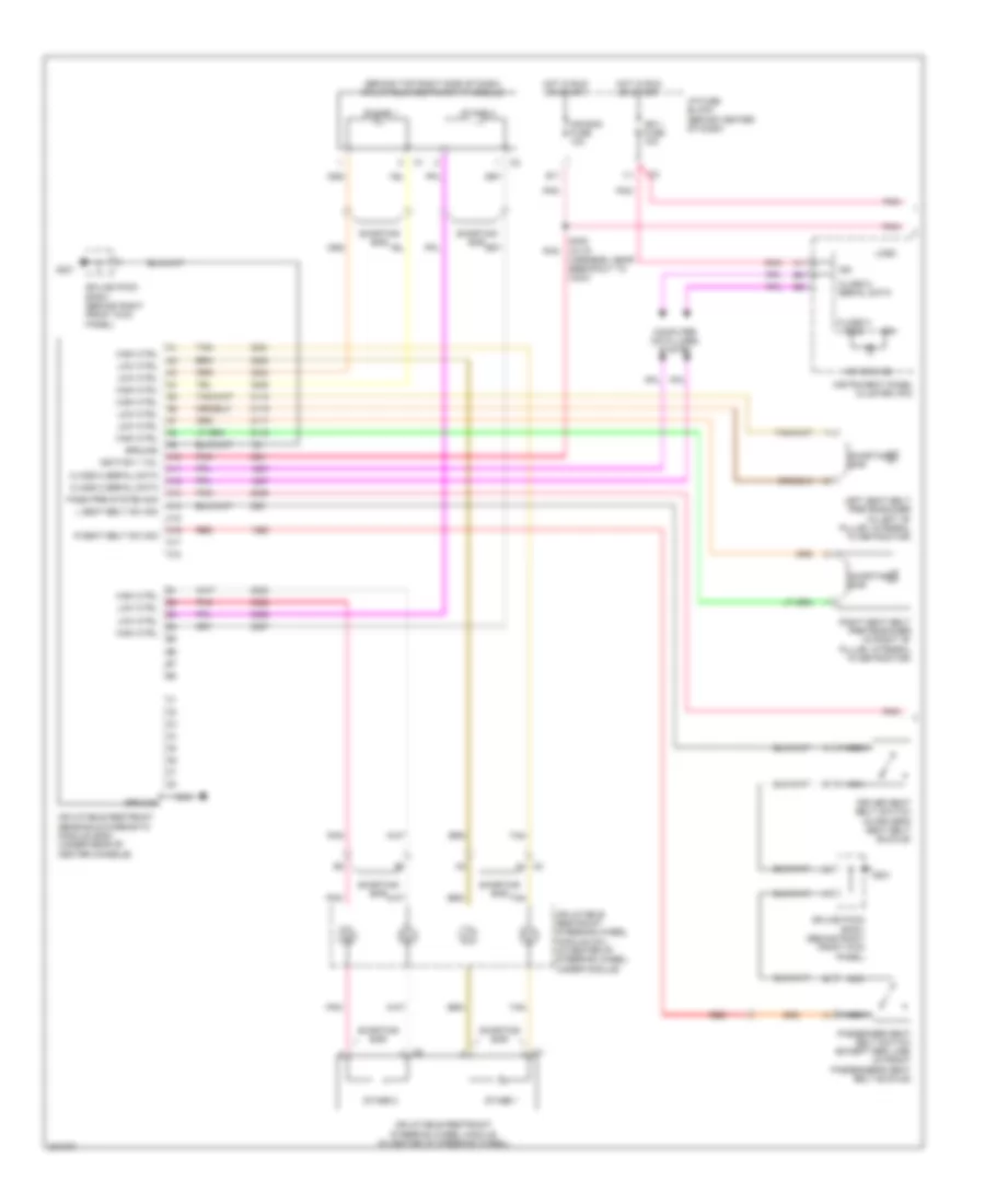 https://portal-diagnostov.com/license.html
Automotive Electricians Portal FZCO
Automotive Electricians Portal FZCO
https://portal-diagnostov.com/license.html
https://portal-diagnostov.com/license.html
Automotive Electricians Portal FZCO
Automotive Electricians Portal FZCOList of elements for Supplemental Restraints Wiring Diagram, without Head Air Bag (1 of 2) for Saturn Vue Red Line 2007:
- (behind top right side of dash) inflatable restraint i/p module
- A1 c3
- A10
- A11
- A12
- A13
- A14
- A15
- A16
- A17
- A18
- Air bag fuse 10a
- Air bag ind
- Class 2 (sdm)
- Class 2 serial data
- Computer data lines system
- Driver seat belt switch (in driver's seat belt buckle)
- E11
- G201
- Ground
- High ctrl
- Hot in run or start
- I/p fuse block (behind center of dash)
- Ign
- Ign 1 fuse 10a
- Ignition 1 vol
- Inflatable restraint sensing & diagnostic module (sdm) (under rear of center console)
- Inflatable restraint steering wheel module (in center of steering wheel)
- Inflatable restraint steering wheel module coil (in center of steering wheel, under module)
- Instrument panel cluster (ipc)
- L seat belt sw sig
- Left seat belt pretensioner (in left "b" pillar, integral to retractor)
- Logic
- Low ctrl
- Nca
- Pass pre system sig
- Passenger seat belt switch (except red line) (in front passenger's seat belt buckle)
- Pnk
- R seat belt sw sig
- Red
- Right seat belt pretensioner (in right "b" pillar, integral to retractor)
- S305 (in i/p harness, near breakout to c204)
- Shorting bar
- Splice pack sp201 (behind right front kick panel)
- Stage 1
- Stage 2
- Tan
Supplemental Restraints Wiring Diagram, without Head Air Bag (2 of 2) for Saturn Vue Red Line 2007
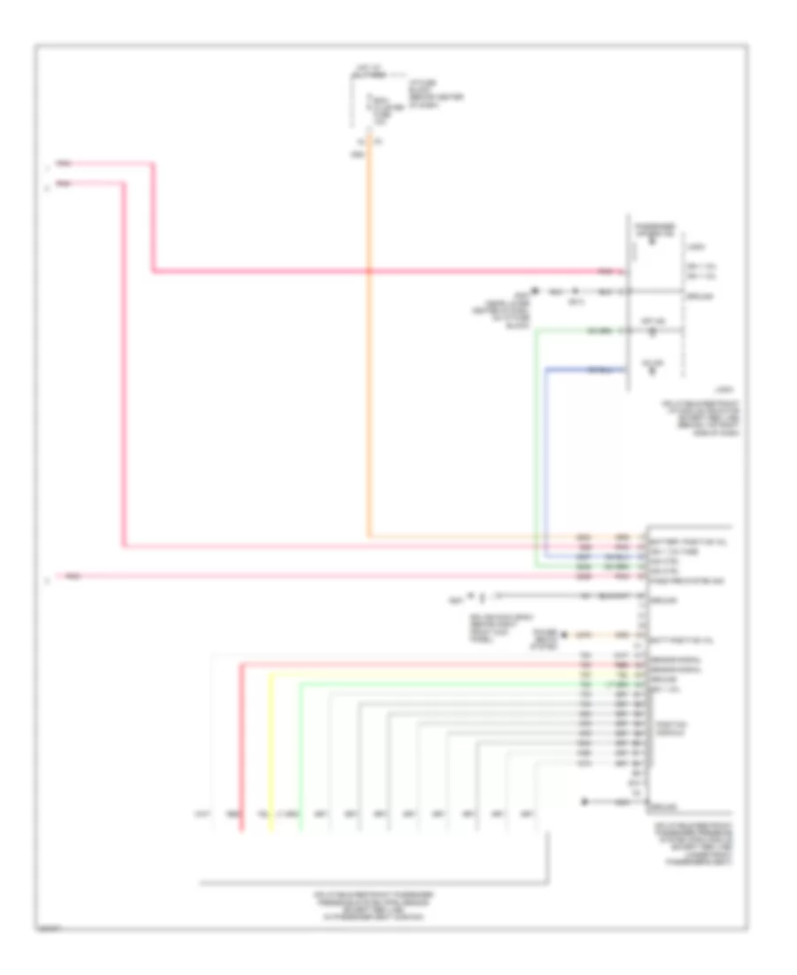 https://portal-diagnostov.com/license.html
Automotive Electricians Portal FZCO
Automotive Electricians Portal FZCO
https://portal-diagnostov.com/license.html
https://portal-diagnostov.com/license.html
Automotive Electricians Portal FZCO
Automotive Electricians Portal FZCOList of elements for Supplemental Restraints Wiring Diagram, without Head Air Bag (2 of 2) for Saturn Vue Red Line 2007:
- B10
- Batt positive vol
- Battery positive vol
- Bcm/ cluster fuse 10a
- G201
- G203 (near lower center of dash, on i/p fuse block)
- Ground
- Hot at all times
- I/p fuse block (behind center of dash)
- Ign 1 vol
- Ign 1 voltage
- Ind ctrl
- Inflatable restraint i/p module indicator (except red line) (behind top right side of dash)
- Inflatable restraint passenger presence system (pps) module (except red line) (under front passenger's seat)
- Inflatable restraint passenger presence system (pps) sensor (except red line) (in passenger seat cushion)
- Logic
- Nca
- Off ind
- On ind
- Pass pre system sig
- Passenger air bag ind
- Pnk
- Position signals
- Power seats system
- Red
- S213
- Sensor signal
- Splice pack sp201 (behind right front kick panel)
TRANSMISSION
2.2L VIN D
2.2L VIN D, A/T Wiring Diagram for Saturn Vue Red Line 2007
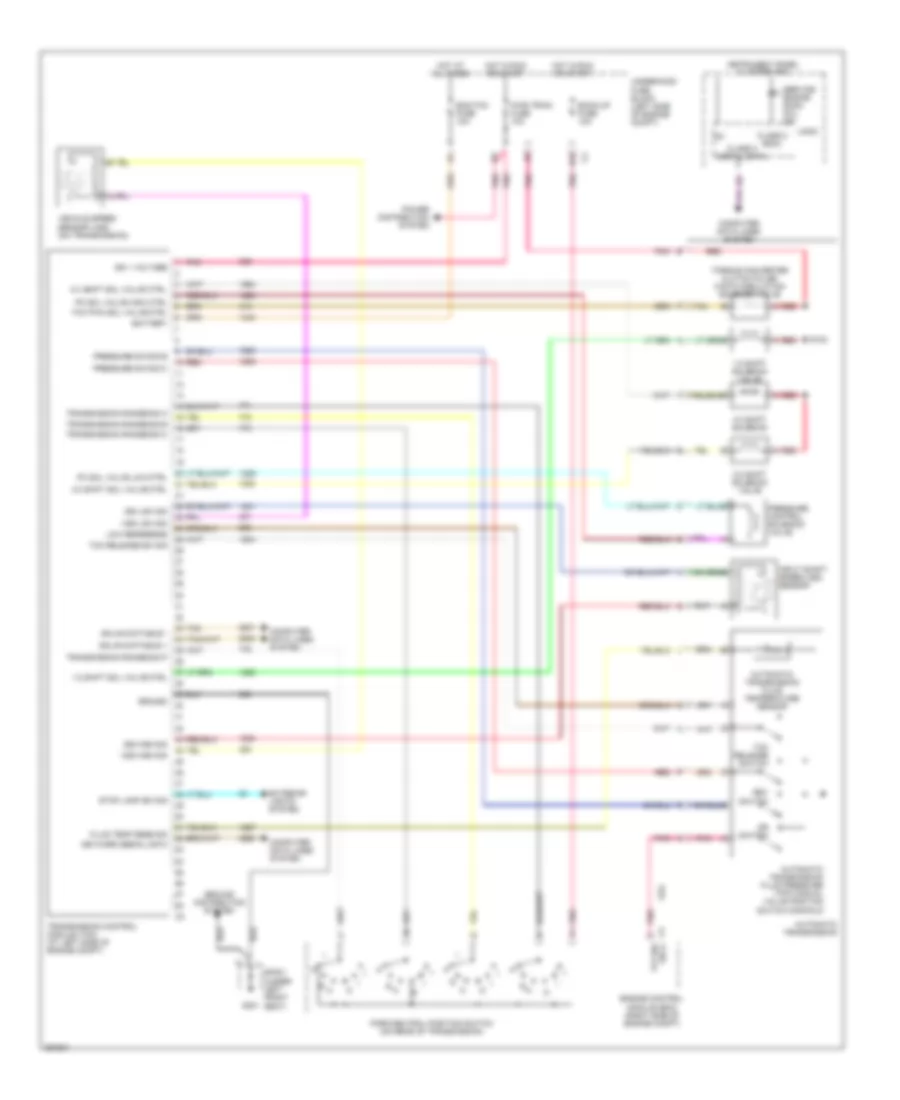 https://portal-diagnostov.com/license.html
Automotive Electricians Portal FZCO
Automotive Electricians Portal FZCO
https://portal-diagnostov.com/license.html
https://portal-diagnostov.com/license.html
Automotive Electricians Portal FZCO
Automotive Electricians Portal FZCOList of elements for 2.2L VIN D, A/T Wiring Diagram for Saturn Vue Red Line 2007:
- 1-2 shift sol valve ctrl
- 1-2 shift solenoid valve
- 2-3 shift sol valve ctrl
- 2-3 shift solenoid valve
- 4-3 shift sol valve ctrl
- 4-3 shift solenoid
- Automatic transmission
- Automatic transmission fluid pressure (tfp) manual valve position switch manifold
- Automatic transmission fluid temperature sensor
- Back-up fuse 10a
- Battery
- Class 2 (ecm)
- Class 2 serial data
- Computer data lines system
- D10
- Dr switch
- Ecm/tcm fuse 10a
- Engine control module (ecm) (right side of engine compt)
- Exterior lights system
- Fluid temp sens sig
- G301
- Gmlan data bus +
- Gmlan data bus -
- Ground
- Ground distribution system
- Hot at all times
- Hot in run or start
- Ig1
- Ign 1 voltage
- Input shaft speed (iss) sensor
- Instrument panel cluster (ipc)
- Iss high sig
- Iss low sig
- Keyword serial data
- Logic
- Low reference
- Park/neutral position switch (on rear of transmission)
- Pc sol valve high ctrl
- Pc sol valve low ctrl
- Pnk
- Power distribution system
- Pressure control solenoid valve
- Pressure sw sig b
- Pressure sw sig c
- Pwr train fuse 10a
- R n
- Red
- Red a
- Rev switch
- S102
- Service engine soon (mil) ind
- Sp301 (under left front seat)
- Stop lamp sw sig
- Tan
- Tcc pwm sol valve ctrl
- Tcc release sw sig
- Tcc release switch
- Tfp sw sig a
- Torque converter clutch pulse width modulation solenoid valve
- Transmission control module (tcm) (at left side of engine compt)
- Transmission range sig a
- Transmission range sig b
- Transmission range sig c
- Transmission range sig p
- Underhood fuse block (left side of engine compt)
- Vehicle speed sensor (vss) (on transmission)
- Vss high sig
- Vss low sig
2.4L VIN Z
2.4L VIN Z, A/T Wiring Diagram for Saturn Vue Red Line 2007
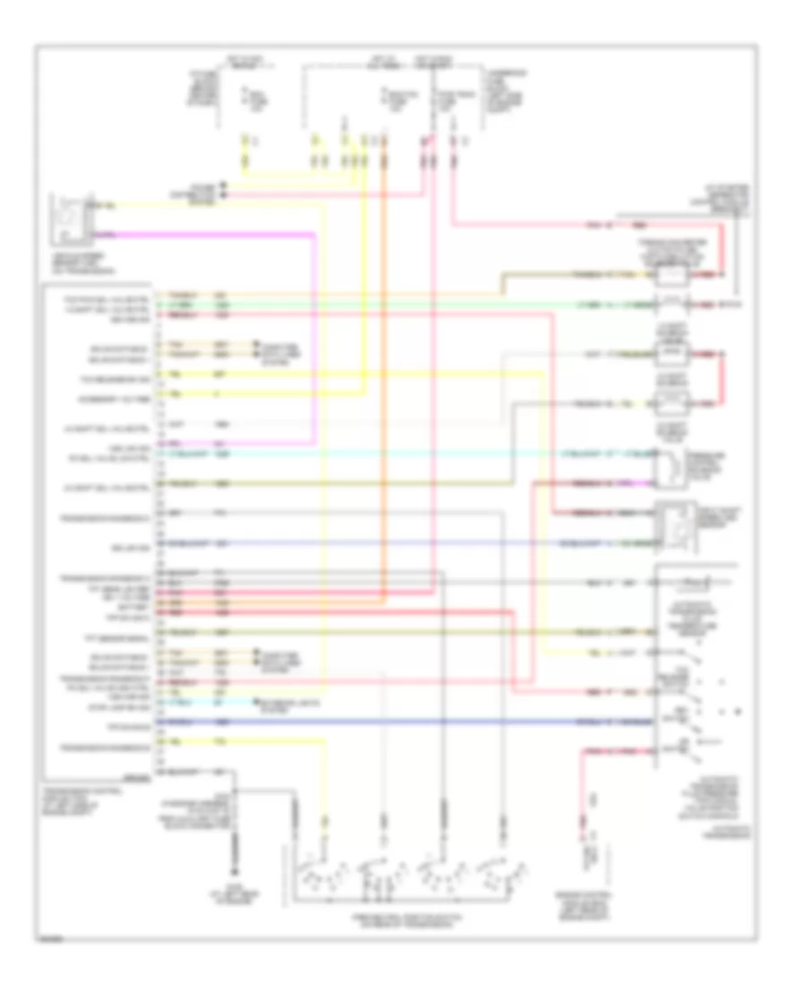 https://portal-diagnostov.com/license.html
Automotive Electricians Portal FZCO
Automotive Electricians Portal FZCO
https://portal-diagnostov.com/license.html
https://portal-diagnostov.com/license.html
Automotive Electricians Portal FZCO
Automotive Electricians Portal FZCOList of elements for 2.4L VIN Z, A/T Wiring Diagram for Saturn Vue Red Line 2007:
- (at starter generator control module breakout)
- 1-2 shift sol valve ctrl
- 1-2 shift solenoid valve
- 2-3 shift sol valve ctrl
- 2-3 shift solenoid valve
- 4-3 shift sol valve ctrl
- 4-3 shift solenoid
- A red
- Accessory voltage
- Automatic transmission
- Automatic transmission fluid pressure (tfp) manual valve position switch manifold
- Automatic transmission fluid temperature sensor
- Battery
- Bcm fuse 10a
- Computer data lines system
- Dr switch
- Ecm/tcm fuse 10a
- Engine control module (ecm) (left rear of engine compt)
- Exterior lights system
- G105 (at left rear of engine)
- Gmlan data bus +
- Gmlan data bus -
- Ground
- Hot at all times
- Hot in acc or run
- Hot in run or start
- I/p fuse block (behind center of dash)
- Input shaft speed (iss) sensor
- Iss high sig
- Iss low sig
- Park/neutral position switch (on rear of transmission)
- Pc sol valve high ctrl
- Pc sol valve low ctrl
- Pnk
- Power distribution system
- Pressure control solenoid valve
- Pwr train fuse 10a
- R n
- Red
- Rev switch
- S102
- S104 (in engine harness, 15 cm (5.91 in) from auxiliary fuse block connector)
- Stop lamp sw sig
- Tan
- Tcc pwm sol valve ctrl
- Tcc release sw sig
- Tcc release switch
- Tfp sw sig a
- Tfp sw sig b
- Tfp sw sig c
- Tft sens low ref ign 1 voltage
- Tft sensor signal
- Torque converter clutch pulse width modulation solenoid valve
- Transmission control module (tcm) (at left side of engine compt)
- Transmission range sig a
- Transmission range sig b
- Transmission range sig c
- Transmission range sig p
- Underhood fuse block (left side of engine compt)
- Vehicle speed sensor (vss) (on transmission)
- Vss high sig
- Vss low sig
3.5L VIN 4
3.5L VIN 4, A/T Wiring Diagram (1 of 2) for Saturn Vue Red Line 2007
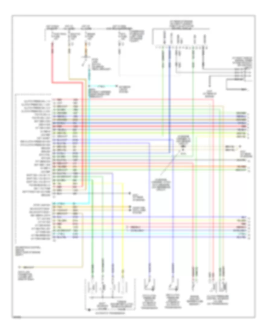 https://portal-diagnostov.com/license.html
Automotive Electricians Portal FZCO
Automotive Electricians Portal FZCO
https://portal-diagnostov.com/license.html
https://portal-diagnostov.com/license.html
Automotive Electricians Portal FZCO
Automotive Electricians Portal FZCOList of elements for 3.5L VIN 4, A/T Wiring Diagram (1 of 2) for Saturn Vue Red Line 2007:
- (at rear of engine, on throttle body) throttle actuator control module
- (at right side of engine, under intake air duct) splice pack sp113
- (in engine harness, in ckp sensor circuit) s135
- (in engine harness, in pcm data sensors low reference circuit)
- 3rd clutch press sw sig
- 3rd clutch pressure switch (at rear of automatic transmission)
- 4th clutch press sw sig
- 4th clutch pressure switch (at rear of automatic transmission)
- 5v ref a
- 5v ref b
- A/t drive sig
- A/t forward sig
- A/t int sig
- A/t iss hi sig
- A/t low sig
- A/t neutral sw
- A/t park sig
- A/t reverse sig
- Automatic transmission
- Batt positive voltage
- Brake fuse 15a
- Clutch press sol 1 hi
- Clutch press sol 1 low
- Clutch press sol 2 hi
- Clutch press sol 2 low
- Clutch pressure control solenoid valves (on transmission)
- Computer data lines system
- Data link connector (lower left side of dash)
- Ecm/tcm fuse 10a
- Ect sen 1 sig
- Ect sen 2 sig
- Engine coolant temperature sensor 1
- Etc ctrl
- Etc fuse 15a
- Etc sig
- Exterior lights system
- F10
- G107 (at rear of engine)
- Gmlan data bus +
- Gmlan data bus -
- Ground
- Hot at all times
- Hot in run or start
- Hot w/ eng main relay energized
- Ign 1
- Ign 1 voltage
- Key serial data
- Low ref
- Mot inhibit
- Oss hi sig
- Powertrain control module (right side of engine compt)
- Pwr train fuse 10a
- Red
- S134
- Shift sol valve 1 hi
- Shift sol valve 2 hi
- Shift sol valve 3 hi
- Shift solenoid valves
- Stop lamp sw
- Stop lamp switch (on brake pedal bracket)
- Tan
- Tcc enable sol hi
- Tcc pc sol hi
- Tcc pc sol low
- Tft sens sig
- Torque converter clutch enable solenoid valve
- Underhood fuse block (left side of engine compt)
3.5L VIN 4, A/T Wiring Diagram (2 of 2) for Saturn Vue Red Line 2007
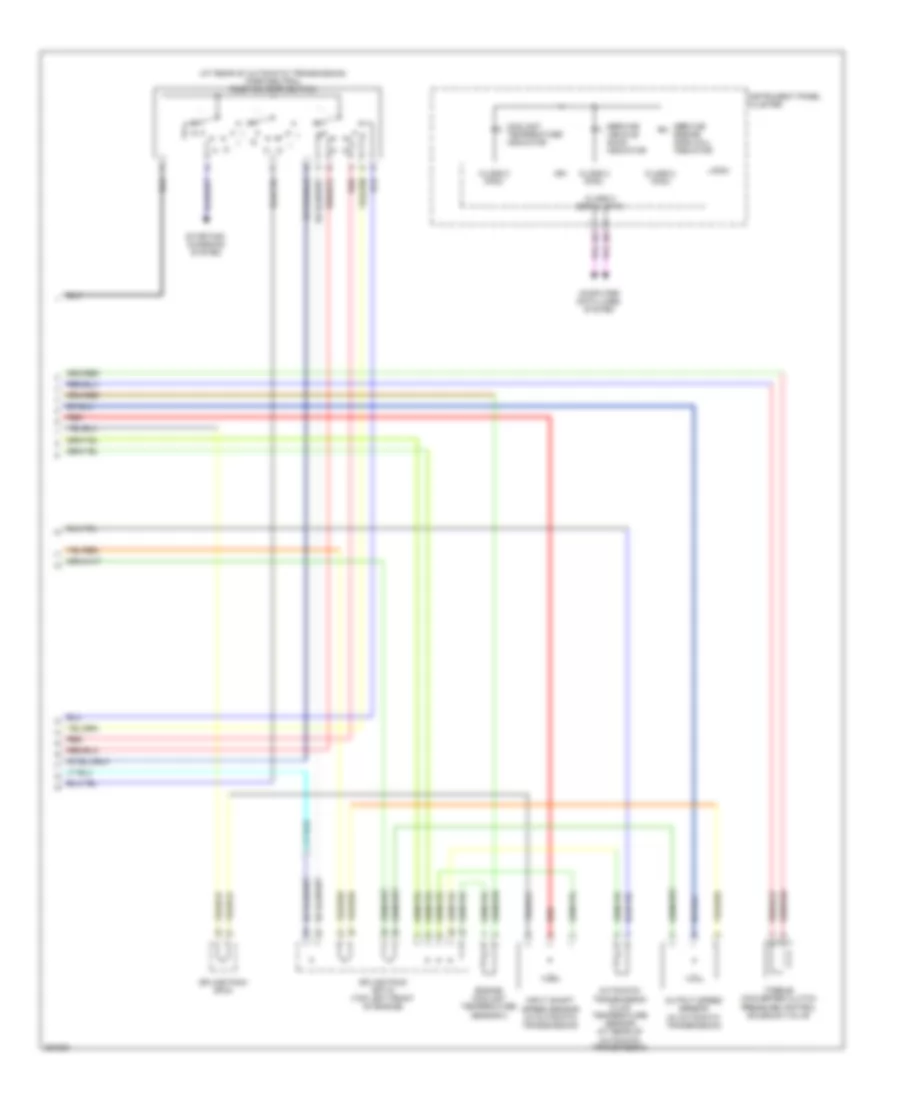 https://portal-diagnostov.com/license.html
Automotive Electricians Portal FZCO
Automotive Electricians Portal FZCO
https://portal-diagnostov.com/license.html
https://portal-diagnostov.com/license.html
Automotive Electricians Portal FZCO
Automotive Electricians Portal FZCOList of elements for 3.5L VIN 4, A/T Wiring Diagram (2 of 2) for Saturn Vue Red Line 2007:
- (at rear of automatic transmission) park/neutral position (pnp) switch
- Automatic transmission fluid temperature sensor (at rear of automatic transmission)
- Class 2 (pcm)
- Class 2 serial data
- Computer data lines system
- Coolant temperature indicator
- Engine coolant temperature sensor 2
- Ign
- Input shaft speed sensor (in automatic transmission)
- Instrument panel cluster
- Logic
- Output speed sensor (in automatic transmission)
- Pressure control solenoid valve
- Red
- Service engine soon (mil) indicator
- Service vehicle soon indicator
- Splice pack sp115 (top left front of engine)
- Splice pack sp44
- Starting/ charging system
- Torque converter clutch
WARNING SYSTEMS
Warning Systems Wiring Diagram for Saturn Vue Red Line 2007
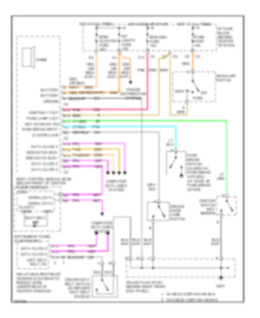 https://portal-diagnostov.com/license.html
Automotive Electricians Portal FZCO
Automotive Electricians Portal FZCO
https://portal-diagnostov.com/license.html
https://portal-diagnostov.com/license.html
Automotive Electricians Portal FZCO
Automotive Electricians Portal FZCOList of elements for Warning Systems Wiring Diagram for Saturn Vue Red Line 2007:
- (ign)
- A10
- A11
- A12
- A14
- B10
- B12
- Battery
- Bcm (ign) fuse 10a
- Bcm/ cluster fuse 10a
- Body control module (bcm) (below front of center floor console)
- C11
- Chime
- Class 2 (sdm)
- Computer data lines system
- Data class 2
- Driver door jamb switch
- Driver seat belt switch (in driver's seat belt buckle)
- G201
- Ground
- Hdlp
- Headlamp switch
- Hot at all times
- Hot in run or start
- I/p fuse block (behind center of dash)
- Ignition 1 volt
- Ignition switch (key minder)
- Inflatable restraint sensing & diagnostic module (sdm) (under rear of center console)
- Instrument panel cluster (ipc)
- Int lights fuse 10a
- Key in ign sw sig
- Left seat belt sw
- Lf door ajar
- Logic
- Nca
- Off
- Park
- Park brake input
- Park fuse 10a
- Park lamp volt
- Pnk
- Power distribution system
- Seat belt ind
- Ser datda bus+
- Ser datda bus-
- Serial data
- Splice pack sp201 (behind right front kick panel)
- Tan
- W/ head curtain air bag
- W/o head curtain air bag
WIPER/WASHER
Wiper/Washer Wiring Diagram for Saturn Vue Red Line 2007
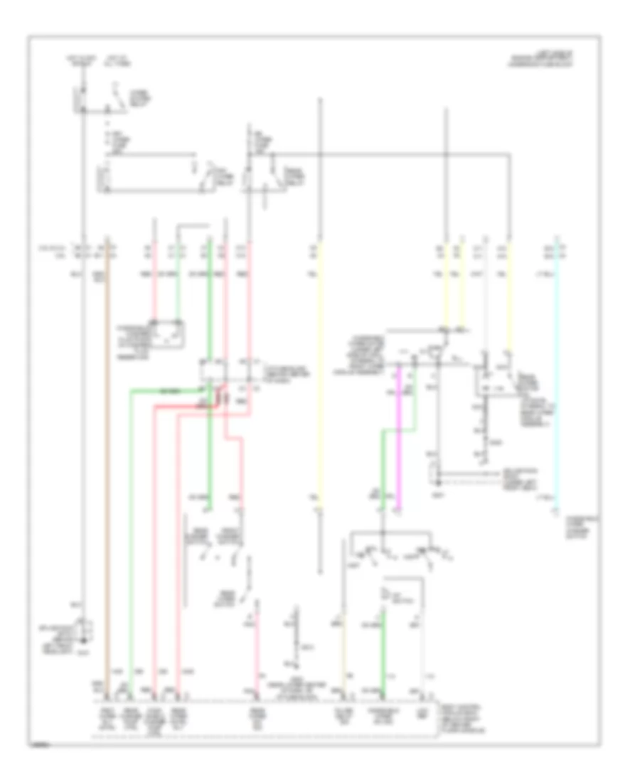 https://portal-diagnostov.com/license.html
Automotive Electricians Portal FZCO
Automotive Electricians Portal FZCO
https://portal-diagnostov.com/license.html
https://portal-diagnostov.com/license.html
Automotive Electricians Portal FZCO
Automotive Electricians Portal FZCOList of elements for Wiper/Washer Wiring Diagram for Saturn Vue Red Line 2007:
- (left side of engine compartment) underhood fuse block
- 2.2l & 2.4l
- 3.5l
- A10
- B10
- B11
- Body control module (bcm) (below front of center floor console)
- C10
- C11
- Frnt wiper rly cntrl
- Front washer switch
- Frt wiper fuse 25a
- Frt wiper relay
- G101
- G203 (near lower center of dash, on i/p fuse block)
- G301
- Hot at all times
- Hot in acc or run
- I/p fuse block (behind center of dash)
- Int
- Int switch
- Low ref
- Mist
- Nca
- Off
- Park
- Pnk
- Pulse/ delay sig
- Rear washer pump ctrl
- Rear washer switch
- Rear wiper cntrl rly
- Rear wiper motor (on liftgate, integral to rear wiper module assembly)
- Rear wiper relay
- Rear wiper sw sig
- Rear wiper switch
- Red
- Rr wiper fuse 15a
- S213
- S400
- Splice pack sp101 (behind left front headlight)
- Splice pack sp301 (under left front seat)
- Wind- shield washer pump ctrl
- Windshield washer fluid pump (in washer fluid reservoir)
- Windshield wiper motor (under left side of cowl, integral to front wiper module assembly)
- Windshield wiper sw sig
- Windshield wiper washer switch
- Wiper system relay

 Čeština
 Dansk
Dansk Deutsch
 Ελληνικά
 English
 English
 Español
 Suomi
Suomi Français
 Français
 עברית
עברית Hrvatski
 Magyar
 Italiano
 한국어
한국어 Nederlands
 Polski
 Português
 Português
 Română
 Русский
 Slovenčina
 Slovenščina
 Svenska
 Türkçe
 中文 (中国)
