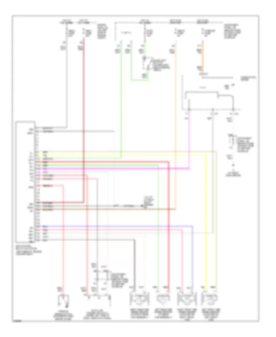
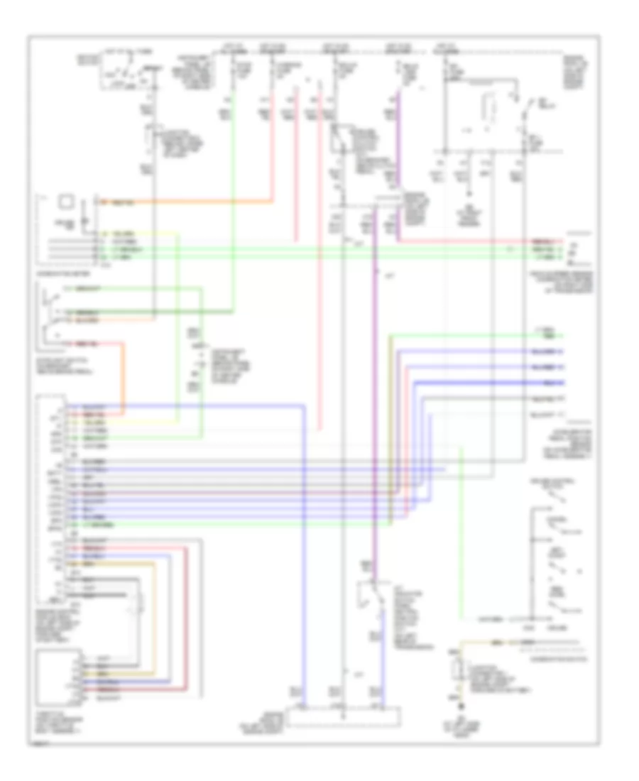
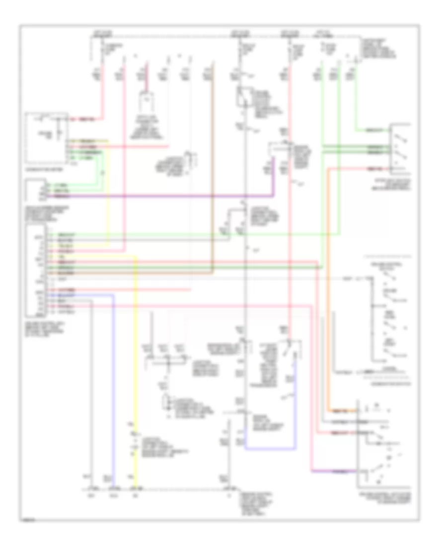
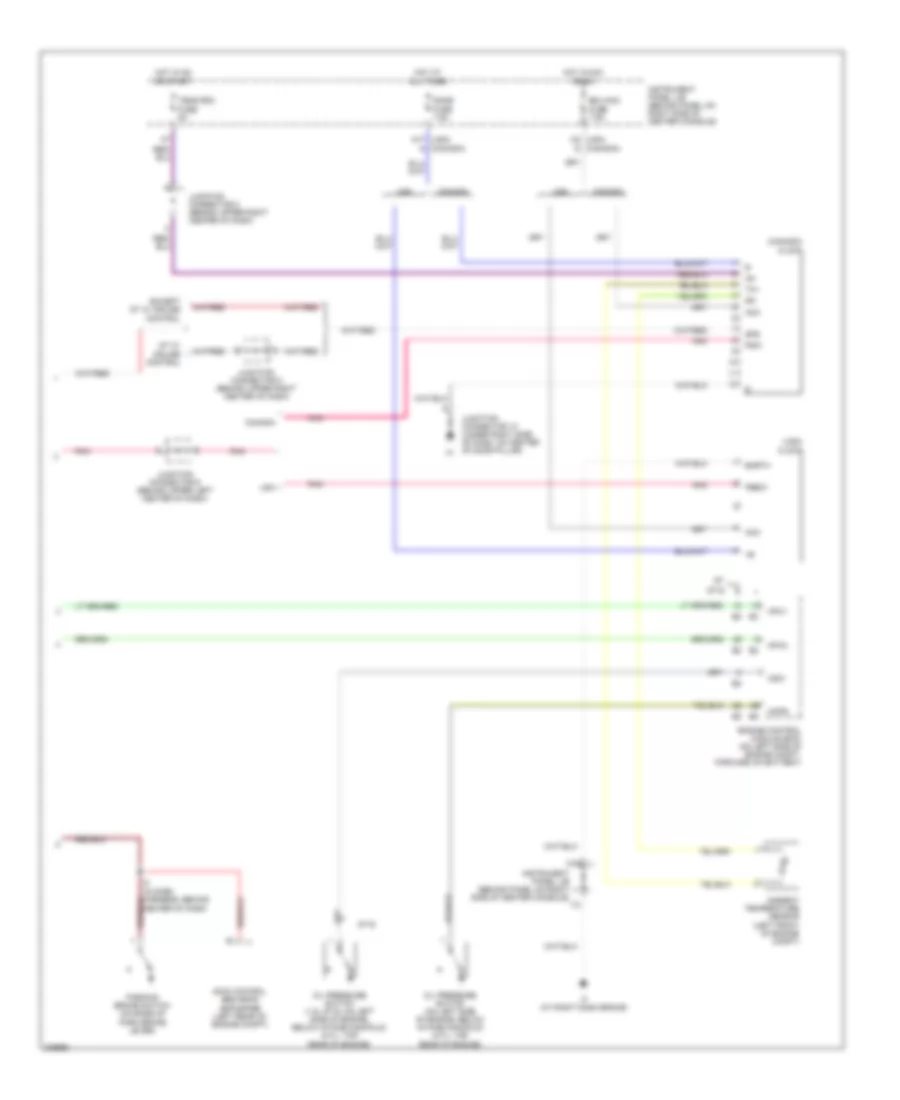
AIR CONDITIONING
Manual A/C Wiring Diagram for Toyota Celica GT 2005
 https://portal-diagnostov.com/license.html
Automotive Electricians Portal FZCO
Automotive Electricians Portal FZCO
https://portal-diagnostov.com/license.html
https://portal-diagnostov.com/license.html
Automotive Electricians Portal FZCO
Automotive Electricians Portal FZCO
List of elements for Manual A/C Wiring Diagram for Toyota Celica GT 2005:
- (1.8 gt-s: left rear of engine compt)
- (1.8l gt: at right front fender) eb
- (at left center of engine compt) e1
- (at left front fender) em
- (at right dash brace) if
- (at right side of firewall)
- (at right side of firewall) ig
- (gt) (gt-s)
- (under right side of dash, in hvac housing) blower motor
- A/c
- A/c condenser fan motor (on left front of engine compartment)
- A/c evaporator temperature sensor (under right side of dash, in hvac housing)
- A/c magnetic clutch & lock sensor (on a/c compressor)
- A/c switch
- A/c triple pressure switch (a/c dual & single pressure switch) (in right front corner of engine compt, behind headlight)
- Acmg
- Blower resistor (below right side of dash, in hvac housing)
- Blower switch
- C12
- C13
- C3 red
- Cds fuse 30a
- Combination meter
- Def
- Dual
- E10
- E12
- E2 (1.8 gt: above center of transmission)
- Ecu-b fuse 7.5a
- Ed (at left side of cylinder head)
- Em (at left front fender)
- Engine control module (ecm) (on left side of engine compt, forward of battery)
- Engine controls system
- Engine coolant temperature sensor (on rear of cylinder head)
- Engine room j/b (on left side of engine compartment)
- Engine room r/b 1 (on left side of engine compartment)
- F28
- F30
- F31
- F32
- Fan
- Fan 1 relay
- Fan 2 relay
- Fan 3 relay
- Fan rly fuse 5a
- Gnd
- Gt-s
- Heater relay
- Hot at all times
- Hot in on or start
- Htr fuse 10a
- Htr fuse 50a
- I2 (in dash harness, behind center of dash)
- Ig+
- Illum
- Instrument panel j/b (behind panel on right side of center console)
- Interior lights system
- Junction connector 1 (on left side of engine compt, forward of battery)
- La/c
- Lcki
- M11
- M13
- Mg/c relay
- Mpx1
- Mpx2
- P10
- P17
- P18
- Pre hp e3
- Radiator fan motor (1.8l gt: in front of engine compt, behind radiator) (1.8l gt-s: left front of engine compt)
- Rdi fuse 30a
- Red
- Single
- Thw
- Warning fuse 5a
ANTI-LOCK BRAKES
Anti-lock Brakes Wiring Diagram for Toyota Celica GT 2005
 https://portal-diagnostov.com/license.html
Automotive Electricians Portal FZCO
Automotive Electricians Portal FZCO
https://portal-diagnostov.com/license.html
https://portal-diagnostov.com/license.html
Automotive Electricians Portal FZCO
Automotive Electricians Portal FZCOList of elements for Anti-lock Brakes Wiring Diagram for Toyota Celica GT 2005:
- (1.8l gt: at right front fender) eb
- (left rear of engine compartment)
- +bm
- +bs
- Abs 1 fuse 50a
- Abs 2 fuse 25a
- Abs ind
- Abs-ig fuse 5a
- Brl
- C12
- C13
- Combination meter
- D/g
- Data link connector (dlc) 3 (under left side of dash, near kick panel)
- Engine room j/b (on left side of engine compt)
- Fl+
- Fl-
- Fr+
- Fr-
- Gnd1
- Gnd2
- Hot at all times
- Hot in on or start
- I12
- If (at right dash brace)
- Ig1
- Instrument panel j/b (behind panel on right side of center console)
- Left front abs speed sensor (mounted on left front hub)
- Left rear abs speed sensor (at rear hub assembly)
- M11
- M20
- Parking brake switch (on base of park brake lever)
- Pkb
- Pnk
- Red
- Right front abs speed sensor (mounted on right front hub)
- Right rear abs speed sensor (on right rear hub assembly)
- Rl+
- Rl-
- Rr+
- Rr-
- Sil
- Skid control ecu w/ actuator
- Stop fuse 10a
- Stoplight switch (on bracket, above brake pedal)
- Stp
- Warning fuse 5a
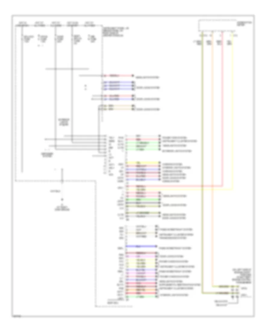
BODY CONTROL MODULES
Body Control Modules Wiring Diagram for Toyota Celica GT 2005
 https://portal-diagnostov.com/license.html
Automotive Electricians Portal FZCO
Automotive Electricians Portal FZCO
https://portal-diagnostov.com/license.html
https://portal-diagnostov.com/license.html
Automotive Electricians Portal FZCO
Automotive Electricians Portal FZCOList of elements for Body Control Modules Wiring Diagram for Toyota Celica GT 2005:
- (on left side of engine compt, forward of battery) engine control module (ecm)
- Acc
- Act+
- Act-
- Actd
- Bltw
- Blvl
- Body ecu
- Body ecu-ig fuse 5a
- C12
- C13
- Celica gt
- Celica gts
- Cltb
- Clte
- Clts
- Combination meter
- Dbkl
- Dcty
- Def
- Def fuse 30a
- Defb
- Defogger system
- Door fuse 20a
- Door locks system
- Drl
- Ecu-acc fuse 7.5a
- Exterior lights system
- Fu+
- Fu-
- Fua
- Headlights system
- Horn
- Horns system
- Hot at all times
- Hot in acc or on
- Hot in on or start
- Hrly
- If (at right dash brace)
- Instrument cluster system
- Instrument panel j/b (behind panel on right side of center console)
- Interior lights system
- Ksw
- Lgcy
- Lswd
- Lswp
- Mpx-b fuse 7.5a
- Mpx1
- Mpx2
- P/w
- Passive restraint system
- Pbkl
- Pcty
- Pkb
- Pnk
- Power tops system
- Power windows system
- Prg
- Pws
- Rda
- Red
- Sg1
- Sg2
- Sg3
- Sg4
- Transmissions system
- Trly
- Ul1
- Ul2
- Ul3
- Warning system
COMPUTER DATA LINES
Computer Data Lines Wiring Diagram for Toyota Celica GT 2005
 https://portal-diagnostov.com/license.html
Automotive Electricians Portal FZCO
Automotive Electricians Portal FZCO
https://portal-diagnostov.com/license.html
https://portal-diagnostov.com/license.html
Automotive Electricians Portal FZCO
Automotive Electricians Portal FZCOList of elements for Computer Data Lines Wiring Diagram for Toyota Celica GT 2005:
- A/b
- Acc
- Bat
- Body ecu (behind panel on right side of center console)
- C12
- C13
- Center air bag sensor assembly (behind lower center of dash)
- Combination meter
- Cruise control ecu (behind left side of dash, near base of "a" pillar)
- D/g
- Data link connector (dlc) 3 (under left side of dash, near kick panel)
- Ed (at left side of cylinder head)
- Engine control module (ecm) (on left side of engine compt, forward of battery)
- Engine room j/b (on left side of engine compt)
- F13
- F18
- Forward of battery)
- Gts
- Hot at all times
- Ignition switch
- Instrument panel j/b (behind panel on right side of center console)
- Junction connector 1 (on left side of engine compt,
- Junction connector 3 (under left side of dash, behind kick panel)
- Junction connector 6 (behind upper left center of dash)
- Lock
- Mpx+
- Mpx-
- Mpx1
- Mpx2
- Obd fuse 7.5a
- Off
- Pnk
- Sil
- Skid control ecu w/ actuator (left rear of engine compt)
- Srs ind
- Start
- Tx+
- Wfse
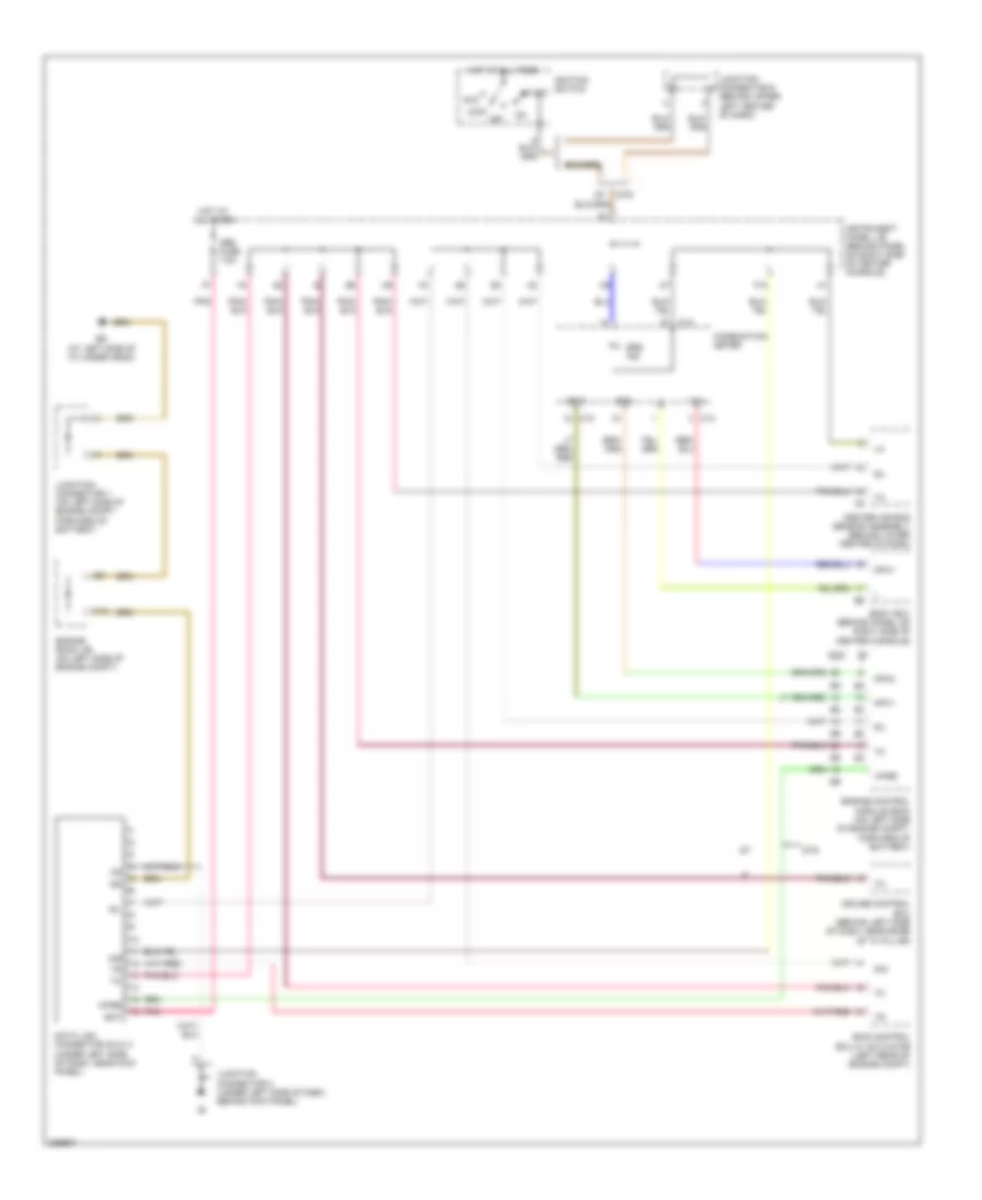
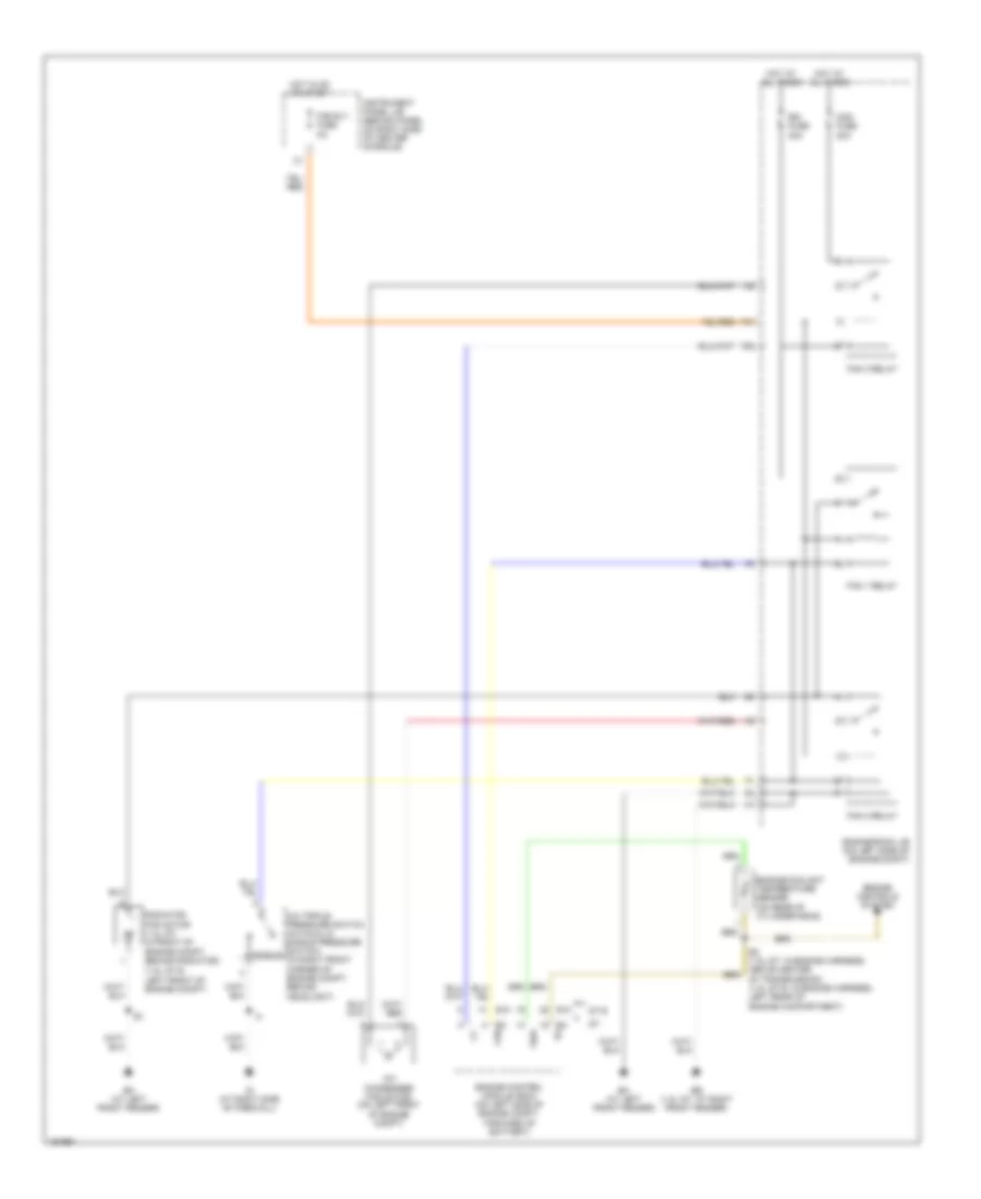
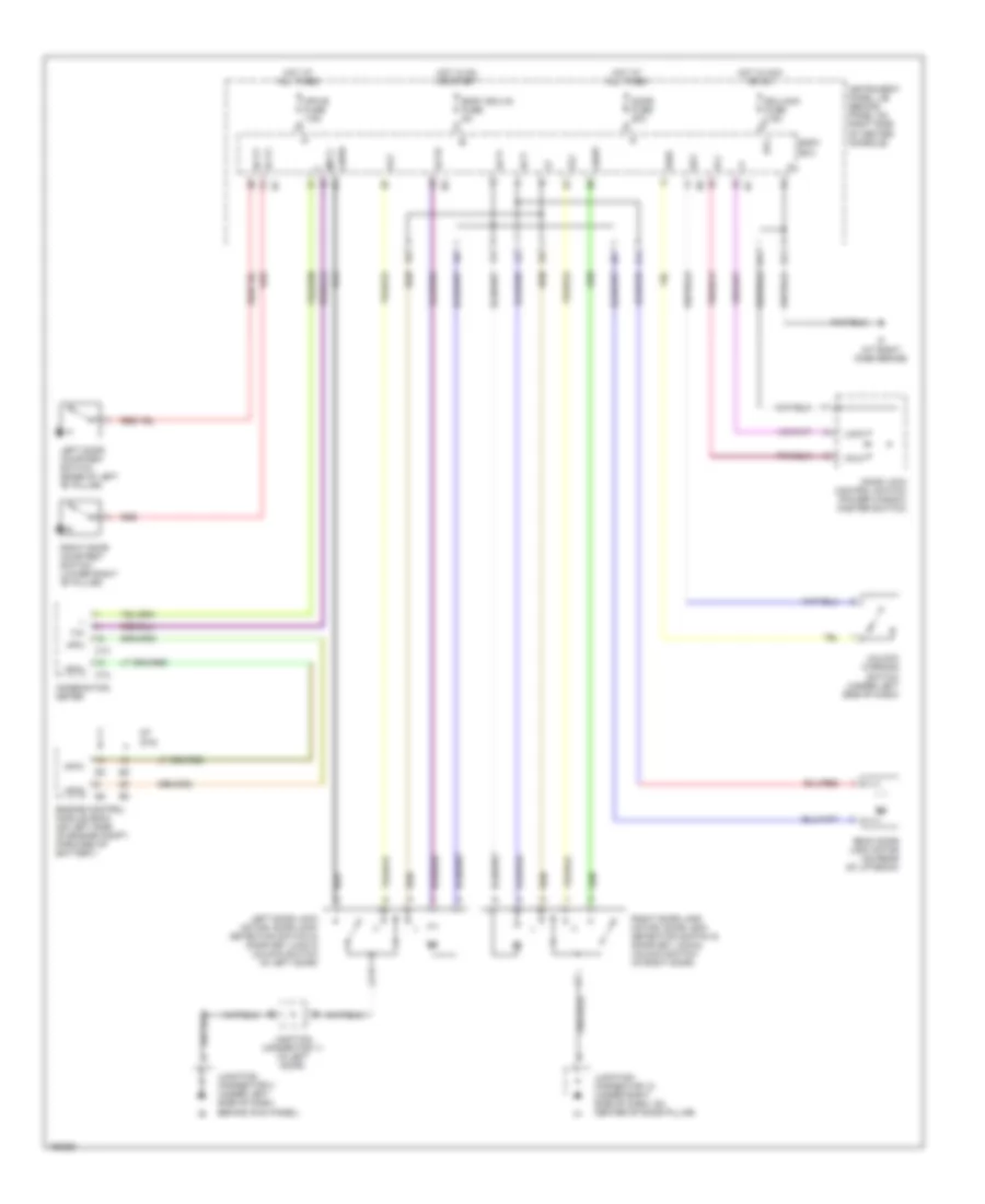
COOLING FAN
Cooling Fan Wiring Diagram for Toyota Celica GT 2005
 https://portal-diagnostov.com/license.html
Automotive Electricians Portal FZCO
Automotive Electricians Portal FZCO
https://portal-diagnostov.com/license.html
https://portal-diagnostov.com/license.html
Automotive Electricians Portal FZCO
Automotive Electricians Portal FZCOList of elements for Cooling Fan Wiring Diagram for Toyota Celica GT 2005:
- (1.8l gt-s: left front of engine compt)
- A/c condenser fan motor (on left front of engine compt)
- A/c triple pressure switch (a/c dual & single pressure switch) single (in right front corner of engine compt, behind headlight)
- Cds fuse 30a
- E10
- E2 (1.8l gt: in engine harness, above center of transmission) (1.8l gt-s: in engine harness, left rear of engine compartment)
- E3 fan
- E4 e2
- Eb (1.8l gt: at right front fender)
- Em (at left front fender)
- Engine control module (ecm) (on left side of engine compt, forward of battery)
- Engine controls system
- Engine coolant temperature sensor (on rear of cylinder head)
- Engine room j/b (on left side of engine compt)
- F28
- F31
- Fan 1 relay
- Fan 2 relay
- Fan 3 relay
- Fan rly fuse 5a
- Gt-s
- Hot at all times
- Hot in on or start
- Ig (at right side of firewall)
- Instrument panel j/b (behind panel on right side of center console)
- Radiator fan motor (1.8l gt: in front of engine compt, behind radiator)
- Rdi fuse 30a
- Thw
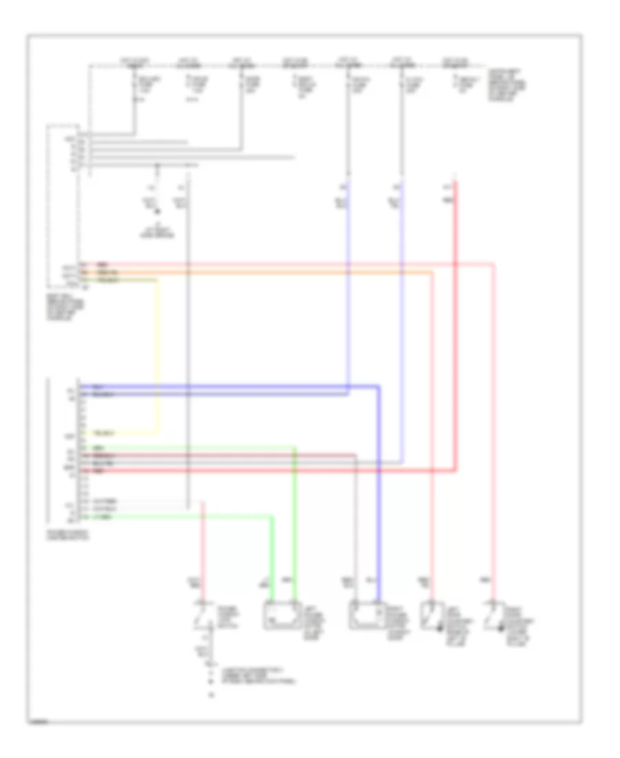
CRUISE CONTROL
Cruise Control Wiring Diagram, GT-S for Toyota Celica GT 2005
 https://portal-diagnostov.com/license.html
Automotive Electricians Portal FZCO
Automotive Electricians Portal FZCO
https://portal-diagnostov.com/license.html
https://portal-diagnostov.com/license.html
Automotive Electricians Portal FZCO
Automotive Electricians Portal FZCOList of elements for Cruise Control Wiring Diagram, GT-S for Toyota Celica GT 2005:
- A/t
- A/t indicator switch (park/ neutral position switch) (a/t) (on left rear of transmission)
- Acc
- Accelerator pedal position sensor (on accelerator pedal assembly)
- Batt
- Bk/up lamp fuse 5a
- C12
- C17
- C18
- C19
- C20
- Cancel
- Ccs
- Combination meter
- Combination switch
- Cruise
- Cruise control clutch switch (m/t) (on bracket, above clutch pedal)
- Cruise control switch
- Cruise ind
- E10
- E12
- Eb (at right front fender)
- Ec (at left side of cylinder head)
- Ecc
- Ecu-ig fuse 5a
- Efi 1 fuse 10a
- Efi fuse 20a
- Efi relay
- Engine control module (ecm) (on left side of engine compt, forward of battery)
- Engine room j/b (on left side of engine compt)
- Epa
- Epa2
- F12
- Ge01
- Hot at all times
- Hot in on or start
- I10
- Ig+
- Ignition switch
- Instrument panel j/b (behind panel on right side of center console)
- Junction connector 1 (on left side of engine compt, forward of battery)
- Junction connector 6 (behind upper left center of dash)
- Lock
- M/t
- M11
- Mrel
- Nca
- Off
- Res/ accel
- Set/ coast
- Spd
- St1-
- Start
- Stop fuse 10a
- Stoplight switch (on bracket, above brake pedal)
- Stp
- Throttle position sensor (on throttle body assembly)
- Vcp2
- Vcpa
- Vehicle speed sensor (combination meter) (on right side of transmission)
- Vpa
- Vpa2
- Vta
- Vta2
- Warning fuse 5a
Cruise Control Wiring Diagram, GT for Toyota Celica GT 2005
 https://portal-diagnostov.com/license.html
Automotive Electricians Portal FZCO
Automotive Electricians Portal FZCO
https://portal-diagnostov.com/license.html
https://portal-diagnostov.com/license.html
Automotive Electricians Portal FZCO
Automotive Electricians Portal FZCOList of elements for Cruise Control Wiring Diagram, GT for Toyota Celica GT 2005:
- A/t
- A/t shift lever position switch (park/ neutral position switch) (on left rear of transmission)
- Bk/up lamp fuse 5a
- C12
- C17
- C18
- C19
- C20
- Cancel
- Ccs
- Combination meter
- Combination switch
- Cruise
- Cruise control actuator (in right front corner of engine compt)
- Cruise control clutch switch (on bracket, above clutch pedal)
- Cruise control ecu (behind left side of dash, near base of "a" pillar)
- Cruise control switch
- Cruise ind
- Data link connector (dlc) 3 (under left side of dash, near kick panel)
- Ecc
- Ect
- Ecu-ig fuse 5a
- Engine control module (ecm) (on left side of engine compt, forward of battery)
- Engine room j/b (on left side of engine compt)
- F10
- F14
- Gnd
- Hot at all times
- Hot in on or start
- I10
- Idl
- Idlo
- Ig+
- Instrument panel j/b (behind panel on right side of center console)
- Junction connector 10 (under right side of dash, on center of door pillar)
- Junction connector 2 (on left side of engine compt, beneath engine room j/b)
- Junction connector 8 (behind upper right center of dash)
- Junction connector 9 (behind right side of dash)
- K10
- M/t
- M11
- Od1
- Res/ accel
- Set/ coast
- Spd
- Stop fuse 10a
- Stoplight switch (on bracket, above brake pedal)
- Stp-
- Vehicle speed sensor (combination meter) (on right side of transmission)
- Warning fuse 5a
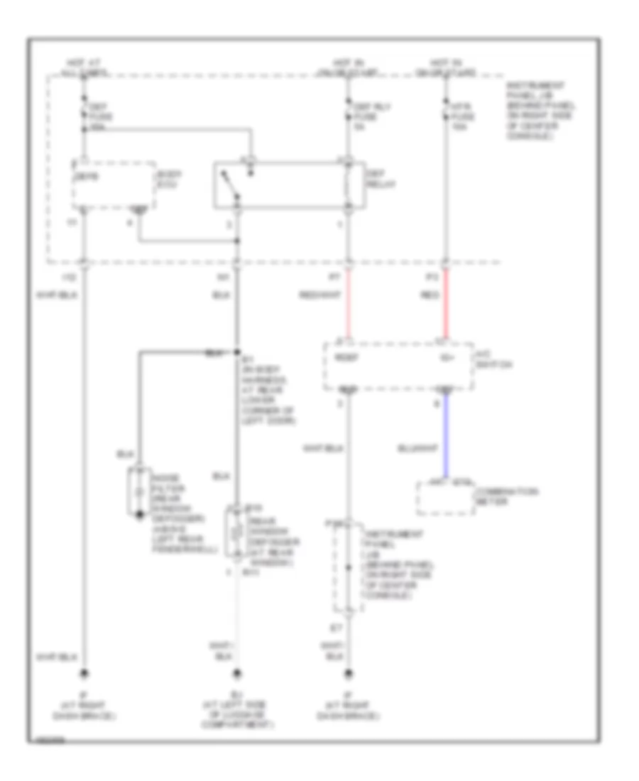
DEFOGGERS
Defoggers Wiring Diagram for Toyota Celica GT 2005
 https://portal-diagnostov.com/license.html
Automotive Electricians Portal FZCO
Automotive Electricians Portal FZCO
https://portal-diagnostov.com/license.html
https://portal-diagnostov.com/license.html
Automotive Electricians Portal FZCO
Automotive Electricians Portal FZCOList of elements for Defoggers Wiring Diagram for Toyota Celica GT 2005:
- A/c switch
- B1 (in body harness, at rear lower corner of left door)
- Bj (at left side of luggage compartment)
- Body ecu
- C13
- Combination meter
- Def
- Def fuse 30a
- Def relay
- Def rly fuse 5a
- Defb
- Gnd
- Hot at all times
- Hot in on or start
- Htr fuse 10a
- I12
- If (at right dash brace)
- Ig+
- Instrument panel j/b (behind panel on right side of center console)
- Noise filter (rear window defogger) (above left rear fenderwell)
- P18
- R10
- R11
- Rdef
- Rear window defogger (at rear window)
- Red
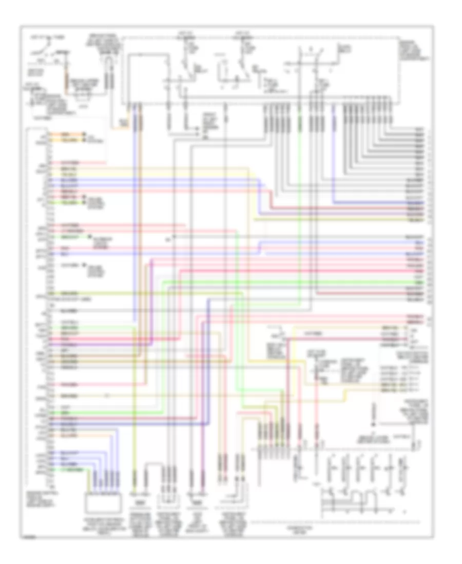
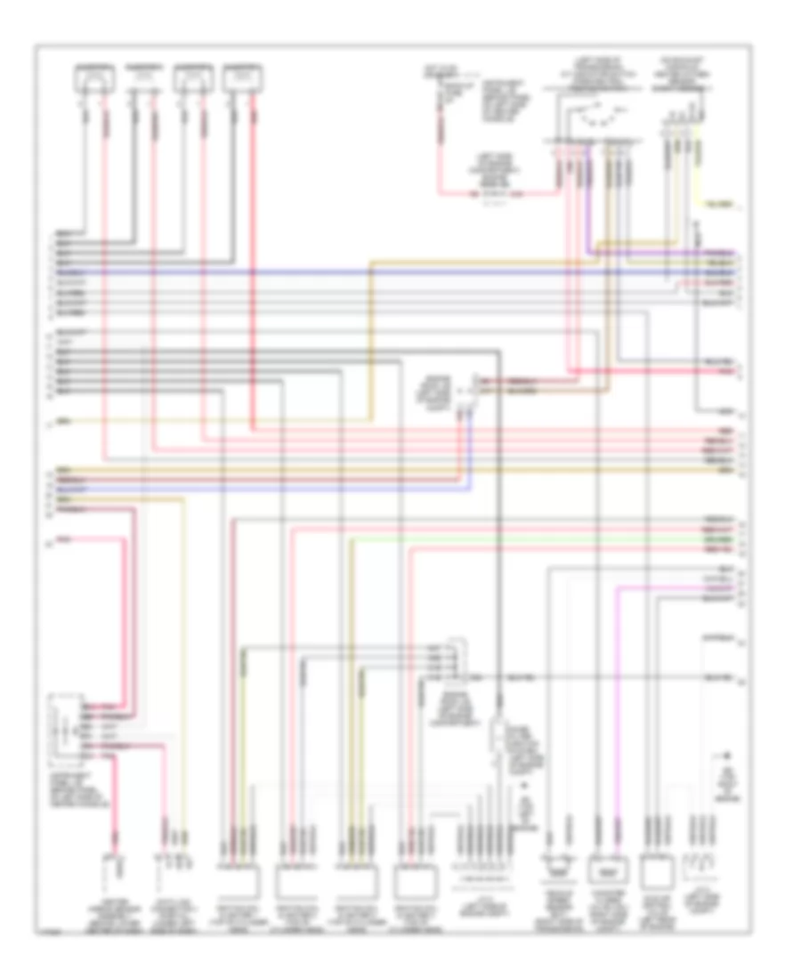
ENGINE PERFORMANCE
1.8L
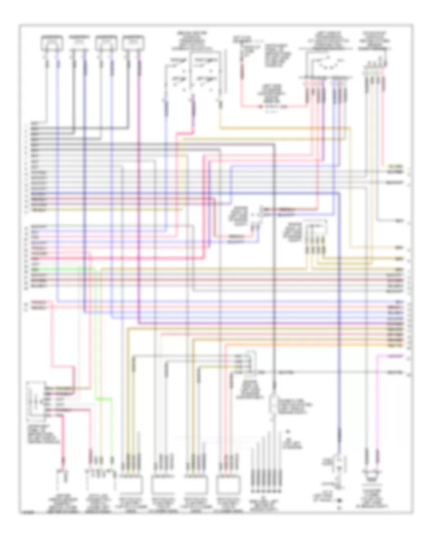
1.8L, Engine Performance Wiring Diagram, GT-S (1 of 4) for Toyota Celica GT 2005
 https://portal-diagnostov.com/license.html
Automotive Electricians Portal FZCO
Automotive Electricians Portal FZCO
https://portal-diagnostov.com/license.html
https://portal-diagnostov.com/license.html
Automotive Electricians Portal FZCO
Automotive Electricians Portal FZCOList of elements for 1.8L, Engine Performance Wiring Diagram, GT-S (1 of 4) for Toyota Celica GT 2005:
- (behind panel on left side of center console)
- (behind upper left center of dash)
- (below accelerator pedal)
- (front of left front fender) em
- (pins 30-35 not used)
- +bm
- A/c system
- A/t oil temp
- Acc
- Accelerator pedal position sensor
- Acis vsv (left front of eng compt)
- Acmg
- B10
- B11
- B12
- Batt
- Body ecu (below center console)
- C/opn relay
- C10
- C11
- C12
- C13
- C14
- C15
- C16
- C23
- C24
- C25
- C26
- Ccs
- Check engine
- Combination meter
- Cruise control system
- Efi 1 fuse 10a
- Efi 2 fuse 10a
- Efi fuse 20a
- Efi relay
- Engine control module (left side of engine compt)
- Engine room j/b (left side of engine compartment)
- Engine room r/b 1 (left side of engine compartment)
- Epa
- Epa2
- Etcs fuse 10a
- Exterior lights system
- F/ps
- F10
- F11
- F12
- F14
- F15
- F18
- F19
- Hot at all times
- Hot in on or start
- I12
- If (behind lower center of dash)
- Ig2 fuse 15a
- Ig2 relay
- Ignition switch
- Igsw
- Ind
- Instrument panel j/b
- Instrument panel j/b (behind panel on left side of center console)
- J/c 6
- Lock
- M11
- M12
- M20
- Mpx1
- Mpx2
- Mrel
- N19
- O/d main switch (below center console)
- Odlp
- Odms
- Pnk
- Pressure switching valve (vsv) (under left rear of vehicle)
- Ptnk
- Sat
- Sftd
- Sftu
- Sg4
- Sil
- Spd
- Sports a/t1
- Sports a/t2
- Sports a/t3
- Sports a/t4
- St1-
- Start
- Stp
- Tach
- Tbp
- Vcp2
- Vcpa
- Vpa
- Vpa2
- Warning fuse 5a
- Wfse
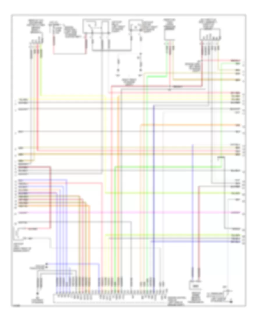
1.8L, Engine Performance Wiring Diagram, GT-S (2 of 4) for Toyota Celica GT 2005
 https://portal-diagnostov.com/license.html
Automotive Electricians Portal FZCO
Automotive Electricians Portal FZCO
https://portal-diagnostov.com/license.html
https://portal-diagnostov.com/license.html
Automotive Electricians Portal FZCO
Automotive Electricians Portal FZCOList of elements for 1.8L, Engine Performance Wiring Diagram, GT-S (2 of 4) for Toyota Celica GT 2005:
- (behind center console) transmission shift switch (combination switch)
- (left side of engine compartment) engine room j/b
- (left side of transmission) a/t indicator switch (park/neutral position switch)
- (on exhaust manifold) heated oxygen sensor (bank 1 sensor 1)
- (top left of engine)
- B14
- Back-up fuse 5a
- C12
- C13
- C17
- C19
- C30
- C31
- C32
- Canister closed valve (vsv) (left side of engine compt)
- Center airbag sensor assembly (behind lower center of dash)
- Data link connector 3 (partial) (under left side of dash)
- E1 (eng harn, left center of engine compt)
- Engine room j/b (left side of engine compartment)
- Engine room j/b (left side of engine compt)
- F13
- F22
- F25
- F26
- Fuel pump
- Gsw2
- Hot in on or start
- Ignition coil & igniter 1 (top of cylinder head)
- Ignition coil & igniter 2 (top of cylinder head)
- Ignition coil & igniter 3 (top of cylinder head)
- Ignition coil & igniter 4 (top of cylinder head)
- Injector 1
- Injector 2
- Injector 3
- Injector 4
- Instrument panel j/b (behind panel on left side of center console)
- J/c 14 (left side of trunk)
- Left-down
- Left-up
- Noise filter (ignition system) (left side of engine compt)
- Ox1a
- Pnk
- Right-down
- Right-up
- Sil
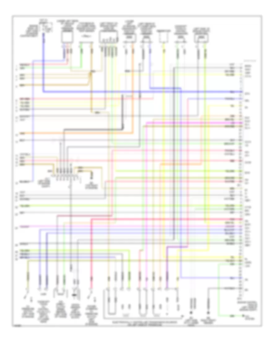
1.8L, Engine Performance Wiring Diagram, GT-S (3 of 4) for Toyota Celica GT 2005
 https://portal-diagnostov.com/license.html
Automotive Electricians Portal FZCO
Automotive Electricians Portal FZCO
https://portal-diagnostov.com/license.html
https://portal-diagnostov.com/license.html
Automotive Electricians Portal FZCO
Automotive Electricians Portal FZCOList of elements for 1.8L, Engine Performance Wiring Diagram, GT-S (3 of 4) for Toyota Celica GT 2005:
- (engine harn, left rear of engine compt)
- (near fuel tank) vapor pressure sensor
- (on throttle body assembly) throttle position motor
- (rear of twc converter) heated oxygen sensor (bank 1, sensor 2)
- (right front of engine compt)
- A-pmp fuse 10a
- Aip
- Air pump (vsv) (right front of engine compt)
- Air pump motor (right front of engine compt)
- Air pump relay (left front of engine compt)
- Airv
- Cooling fans system
- E01
- E02
- E10
- Ed (top right of engine)
- Engine control module (left side of engine compt)
- Engine room r/b 1 (left side of engine compartment)
- Fan
- Hot at all times
- Ht2
- Igf
- Igt1
- Igt2
- Igt3
- Igt4
- Ne+
- Ne-
- Oil pressure switch (vvtl) (left side of engine)
- Ox1b
- Red
- Shield
- Slt+
- Slt-
- Tha
- Tho
- Thw
- Vehicle speed sensor (rear of transmission)
- Vsv
- Vta
- Vta2
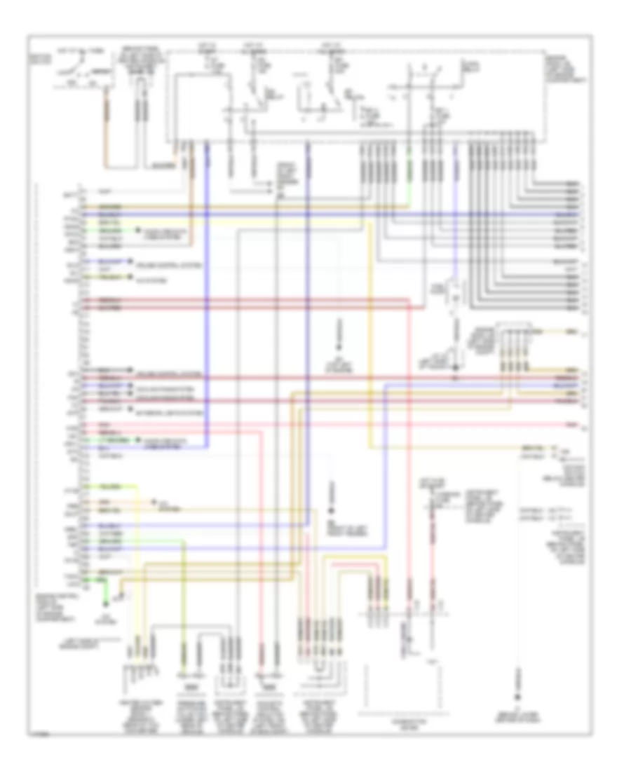
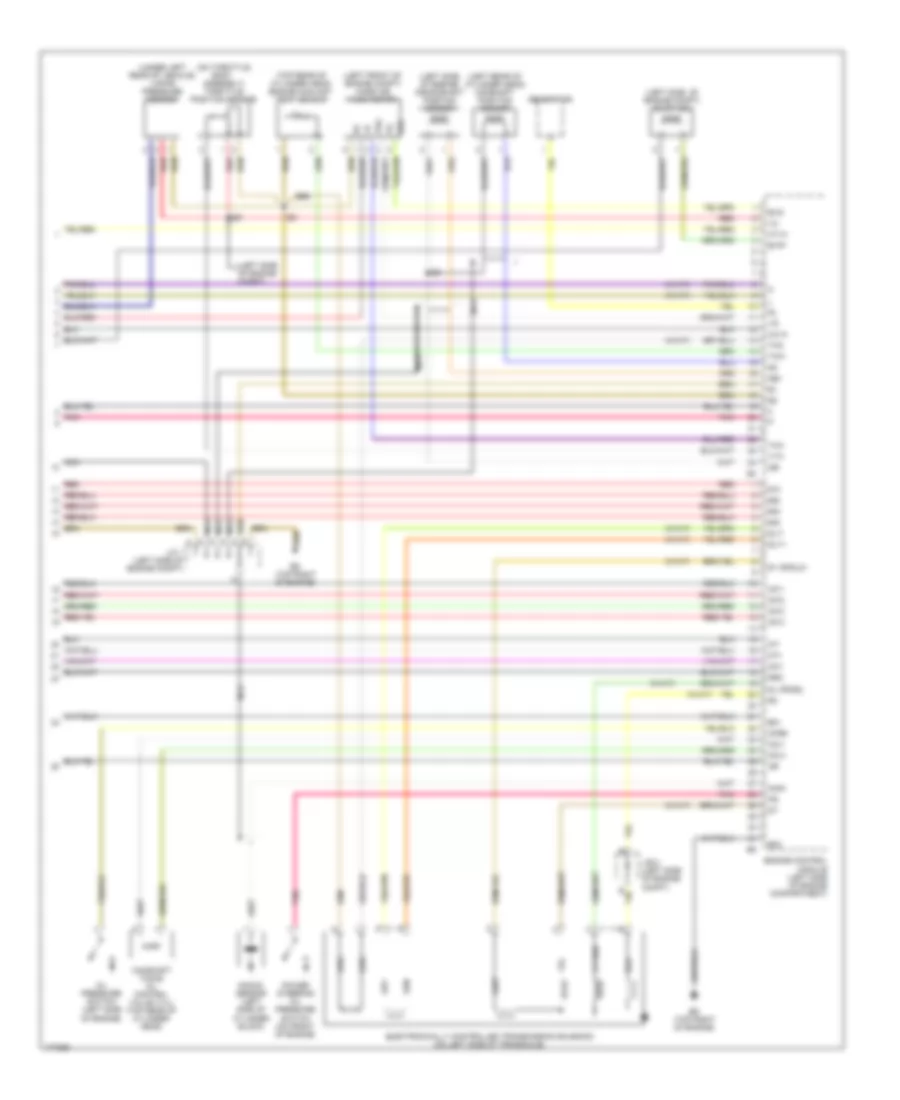
1.8L, Engine Performance Wiring Diagram, GT-S (4 of 4) for Toyota Celica GT 2005
 https://portal-diagnostov.com/license.html
Automotive Electricians Portal FZCO
Automotive Electricians Portal FZCO
https://portal-diagnostov.com/license.html
https://portal-diagnostov.com/license.html
Automotive Electricians Portal FZCO
Automotive Electricians Portal FZCOList of elements for 1.8L, Engine Performance Wiring Diagram, GT-S (4 of 4) for Toyota Celica GT 2005:
- (left front of engine compt) mass air flow meter
- (left rear of cylinder head) camshaft position sensor
- (left side of engine compt) evap vsv
- (lower left of engine) crankshaft position sensor
- (top rear of cylinder head) engine coolant temp sensor
- (under left rear of vehicle) vapor pressure sensor
- A/c system
- Airp
- Camshaft timing oil control valve (vvl) (front left of cylinder head)
- Camshaft timing oil control valve (vvt)
- Ccv
- Dsl
- E03
- E11
- E12
- E2g
- Eb (right front fender)
- Ec (left side of cylinder head)
- Ed (top right of engine)
- Eknk
- Electronically controlled transmission solenoid (on left side of transaxle)
- Engine control module (left side of engine compt)
- Engine room j/b (left side of engine compartment)
- Evg
- Evp1
- F20
- Ge01
- Generator
- Hot in start
- Ht1a
- Ht1b
- J/c 1 (left side of engine compt)
- Knk1
- Knock sensor (left side of cylinder block)
- Lcki
- Me01
- Mops
- Nc+
- Nc-
- Nca
- Nt+
- Nt-
- O/d direct clutch speed sensor (left side of trans)
- Ocv+
- Ocv-
- Oil pressure switch (left side of engine)
- Osw
- Ovl+
- Ovl-
- Ox1a
- Ox1b
- Pnk
- Power steering oil pressure switch (left side of engine)
- Red
- Shield
- Sl1+
- Sl1-
- Sl2+
- Sl2-
- St fuse 7.5a
- Sta
- Tha
1.8L, Engine Performance Wiring Diagram, GT (1 of 3) for Toyota Celica GT 2005
 https://portal-diagnostov.com/license.html
Automotive Electricians Portal FZCO
Automotive Electricians Portal FZCO
https://portal-diagnostov.com/license.html
https://portal-diagnostov.com/license.html
Automotive Electricians Portal FZCO
Automotive Electricians Portal FZCOList of elements for 1.8L, Engine Performance Wiring Diagram, GT (1 of 3) for Toyota Celica GT 2005:
- (behind panel on left side of center console) instrument panel j/b
- (front of left front fender) em
- (left side of engine compt)
- A/c system
- Acc
- Acmg
- Acoustic control induction system vsv (left front of eng compt)
- B10
- B11
- B12
- Batt
- C/opn relay
- C10
- C11
- C12
- C13
- C14
- C15
- C16
- C23
- C24
- C25
- C26
- Check engine
- Combination meter
- Computer data lines system
- Cooling fans system
- Cruise control system
- E03
- Eb (front of left front fender)
- Ec (top left of engine)
- Efi 1 fuse 10a
- Efi 2 fuse 10a
- Efi fuse 20a
- Efi relay
- Engine control module (left side of engine compartment)
- Engine room j/b (left side of engine compartment)
- Engine room j/b (left side of engine compt)
- Exterior lights system
- F/ps
- F10
- F11
- F12
- F13
- F14
- F15
- F18
- F19
- F20
- F25
- F26
- F27
- Fan
- Fuel pump
- Heated oxygen sensor (bank 1, sensor 2) (rear of twc converter)
- Hot at all times
- Hot in on or start
- Hot in start
- Ht1b
- Ht2
- I12
- Idlo
- If (behind lower center of dash)
- Ig2 fuse 15a
- Ig2 relay
- Ignition switch
- Igsw
- Ind
- Instrument panel j/b (behind panel on left side of center console)
- J/c 14 (left side of trunk)
- Lcki
- Lock
- M11
- M12
- Mpx1
- Mpx2
- Mrel
- N19
- O/d main switch (below center console)
- Od1
- Odlp
- Odms
- Ox1b
- Pnk
- Pre
- Pressure switching valve (vsv) (under left rear of vehicle)
- Ptnk
- Sil
- Spd
- St fuse 7.5a
- Sta
- Start
- Stp
- Tach
- Tbp
- Vsv
- Warning fuse 5a
1.8L, Engine Performance Wiring Diagram, GT (2 of 3) for Toyota Celica GT 2005
 https://portal-diagnostov.com/license.html
Automotive Electricians Portal FZCO
Automotive Electricians Portal FZCO
https://portal-diagnostov.com/license.html
https://portal-diagnostov.com/license.html
Automotive Electricians Portal FZCO
Automotive Electricians Portal FZCOList of elements for 1.8L, Engine Performance Wiring Diagram, GT (2 of 3) for Toyota Celica GT 2005:
- (left side of engine compartment) engine room j/b
- (left side of transmission) a/t indicator switch (park/neutral position switch)
- (on exhaust manifold) heated oxygen sensor (bank 1 sensor 1)
- B14
- Back-up fuse 5a
- C12
- C13
- C17
- C19
- C30
- C31
- C32
- Canister closed valve (vsv) (right side of engine compt)
- Center airbag sensor assembly (behind lower center of dash)
- Data link connector 3 (partial) (under left side of dash)
- Ec (top left of engine)
- Ed (top right of engine)
- Engine room j/b (left side of engine compartment)
- Engine room j/b (left side of engine compt)
- F22
- Gsw2
- Hot in on or start
- Idle air control valve (left rear of engine)
- Ignition coil & igniter 1 (top of cylinder head)
- Ignition coil & igniter 2 (top of cylinder head)
- Ignition coil & igniter 3 (top of cylinder head)
- Ignition coil & igniter 4 (top of cylinder head)
- Injector 1
- Injector 2
- Injector 3
- Injector 4
- Instrument panel j/b (behind panel on left side of center console)
- J/c 2 (left side of engine compt)
- Nca
- Noise filter (ignition system) (left side of engine compt)
- Ox1a
- Pnk
- Red
- Sil
- Vehicle speed sensor (ect) (right side of transmission)
1.8L, Engine Performance Wiring Diagram, GT (3 of 3) for Toyota Celica GT 2005
 https://portal-diagnostov.com/license.html
Automotive Electricians Portal FZCO
Automotive Electricians Portal FZCO
https://portal-diagnostov.com/license.html
https://portal-diagnostov.com/license.html
Automotive Electricians Portal FZCO
Automotive Electricians Portal FZCOList of elements for 1.8L, Engine Performance Wiring Diagram, GT (3 of 3) for Toyota Celica GT 2005:
- #10
- #20
- #30
- #40
- (left front of engine compt) mass air flow meter
- (left rear of cylinder head) camshaft position sensor
- (left side of engine compt) evap vsv
- (left side of engine compt)
- (left side of engine) crankshaft position sensor
- (on throttle body assembly) throttle position sensor
- (top rear of cylinder head) engine coolant temp sensor
- (under left rear of vehicle) vapor pressure sensor
- (w/a/t)
- Camshaft timing oil control valve (vvl) (top rear of cylinder head)
- Ccv
- E01
- E02
- E2g
- Ed (top right of engine)
- Electronically controlled transmission solenoid (on left side of transaxle)
- Engine control module (left side of engine compartment)
- Evg
- Evp1
- Generator
- Ht1a
- Igf
- Igt1
- Igt2
- Igt3
- Igt4
- J/b 2 (left side of engine compt)
- J/c 1 (left side of engine compt)
- Knk1
- Knock sensor (left side of cylinder block)
- Mops
- Nca
- Ne+
- Ne-
- Nt+
- Nt-
- Ocv+
- Ocv-
- Oil pressure switch (left side of engine)
- Ox1a
- Pnk
- Power steering oil pressure switch (on front of engine)
- Red
- Rso
- S1 or sl2+
- Sl or dsl
- Slt+
- Slt-
- Tha
- Tho
- Thw
- Vta
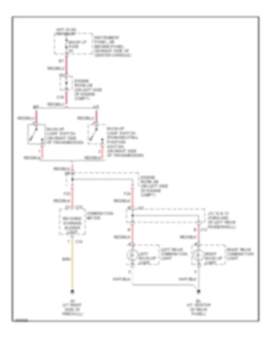
EXTERIOR LIGHTS
Back-up Lamps Wiring Diagram for Toyota Celica GT 2005
 https://portal-diagnostov.com/license.html
Automotive Electricians Portal FZCO
Automotive Electricians Portal FZCO
https://portal-diagnostov.com/license.html
https://portal-diagnostov.com/license.html
Automotive Electricians Portal FZCO
Automotive Electricians Portal FZCOList of elements for Back-up Lamps Wiring Diagram for Toyota Celica GT 2005:
- A/t
- Back-up light switch (on right side of transmission)
- Back-up light switch (park/neutral position switch) (on right side of transmission)
- Bk/up lp fuse 5a
- Bl (at center of rear panel)
- C12
- C19
- Combination meter
- Engine room j/b (on left side of engine compt)
- F23
- F24
- Hot in on or start
- Ih (at right side of firewall)
- Instrument panel j/b (behind panel on right side of center console)
- J/c 12 & 13 (forward of left rear fenderwell) j13
- J12
- Left back-up light
- Left rear combination light
- M/t
- Reverse warning buzzer light
- Right back-up light
- Right rear combination light
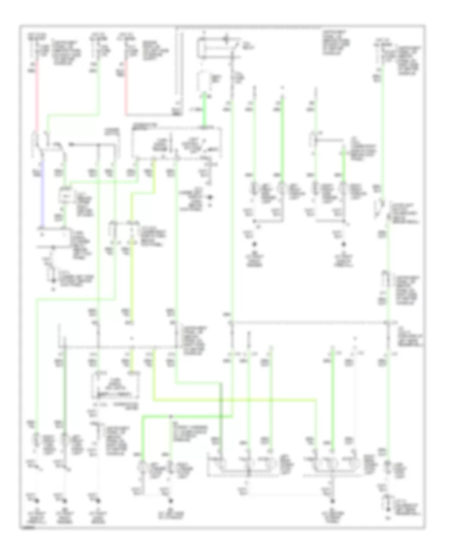
Exterior Lamps Wiring Diagram for Toyota Celica GT 2005
 https://portal-diagnostov.com/license.html
Automotive Electricians Portal FZCO
Automotive Electricians Portal FZCO
https://portal-diagnostov.com/license.html
https://portal-diagnostov.com/license.html
Automotive Electricians Portal FZCO
Automotive Electricians Portal FZCOList of elements for Exterior Lamps Wiring Diagram for Toyota Celica GT 2005:
- Alt fuse 120a
- B2 (in body harness, at lower middle of liftback opening)
- Bk (at left side of liftback)
- Bl (at center of rear panel)
- Body ecu
- C12
- C13
- C15
- Combination meter
- Combination switch
- D j5
- E j4
- Eb (at right front fender)
- Engine room j/b (on left side of engine compt)
- F29
- Haz fuse 10a
- Hazard switch
- Head
- High mount stop light
- Hot at all times
- Hot in on or start
- I12
- If (at right dash brace)
- Ig (at right side of firewall)
- Instrument panel j/b (behind panel on right side of center console)
- J/c 12 & 13 (forward of left rear fenderwell)
- J/c 14 (on rear of left rear fenderwell)
- J/c 3 (under left side of dash, behind kick panel)
- J/c 4 & 5 (under right side of dash, behind kick panel)
- J/c 4 & 5 (under right side of dash, j4 behind kick panel)
- J/c 7 (behind upper right center of dash)
- J12
- J13
- Left
- Left front parking light
- Left front side marker light
- Left front turn signal light
- Left license plate light
- Left rear combin- ation light
- Light control switch
- M14
- M20
- O11
- O12
- O13
- Off
- Red
- Right
- Right front parking light
- Right front side marker light
- Right front turn signal light
- Right license plate light
- Right rear combin- ation light
- Stop
- Stop fuse 10a
- Stoplight switch (on bracket, above brake pedal)
- Tail
- Tail fuse 10a
- Tail relay
- Turn
- Turn fuse 7.5a
- Turn signal flasher relay (behind left kick panel)
- Turn signal ind lights
- Turn signal switch
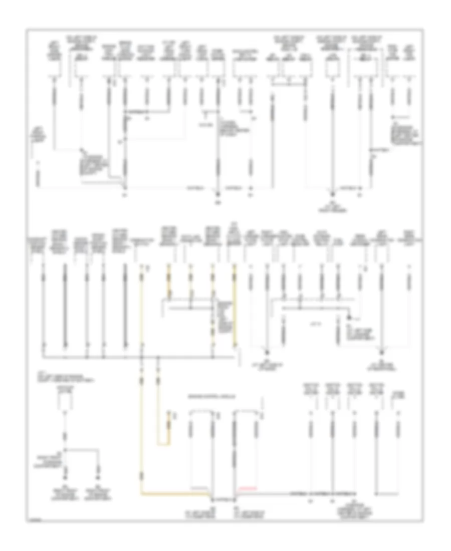
GROUND DISTRIBUTION
Ground Distribution Wiring Diagram, GT-S (1 of 2) for Toyota Celica GT 2005
 https://portal-diagnostov.com/license.html
Automotive Electricians Portal FZCO
Automotive Electricians Portal FZCO
https://portal-diagnostov.com/license.html
https://portal-diagnostov.com/license.html
Automotive Electricians Portal FZCO
Automotive Electricians Portal FZCOList of elements for Ground Distribution Wiring Diagram, GT-S (1 of 2) for Toyota Celica GT 2005:
- (on left side of engine compt) engine room j/b
- (on left side of engine compt) engine room r/b 1
- (on left side of engine compt) engine room r/b 2
- (w/ hid) left head light assembly
- A/c mag- netic clutch & lock sensor
- Air pump motor
- Auto antenna control relay
- Bj (at left side of luggage compartment)
- Bk (at left side of liftback)
- Bl (at center of rear panel)
- Brake fluid level warning switch
- C12
- C16
- Camshaft position sensor shield
- Combi- nation meter
- Combination switch
- Crank- shaft position sensor shield
- Data link connector
- Daytime running light resistor
- Door control receiver
- Drl 3 relay
- Drl 4 relay
- E1 (in engine harness, at left center of engine compartment)
- E1 (in engine harness, at left center of engine compt)
- E10
- E12
- Ec (at left side of cylinder head)
- Ed (at left side of cylinder head)
- Efi relay
- Em (at left front fender)
- En (right front of engine compartment)
- Engine con- trol module
- Engine control module
- Engine room j/b (on left side of engine compt)
- Eo (right front of engine compartment)
- F13
- F25
- F26
- Fan 2 relay
- Fuel pump
- Heated oxygen sensor (bank 1 sensor 1)
- Heated oxygen sensor (bank 1 sensor 1) shield
- Heated oxygen sensor (bank 1 sensor 2)
- Heated oxygen sensor (bank 1 sensor 2) shield
- High mounted stop light
- Htr relay
- I1 (in dash harness, behind center of dash)
- Ig2 relay
- Ignition coil & igniter
- J/c 1 (on left side of engine compt, forward of battery)
- J/c 14
- Knock sensor (bank 1) shield
- Left front fog light
- Left front parking light
- Left front side marker light
- Left front turn signal light
- Left head- light (low)
- Left license plate light
- Left rear combination light
- Nca
- Noise filter
- R11
- Radi- ator fan motor
- Rear window defogger
- Right license plate light
- Right rear combination light
- Skid control ecu w/ actuator
- W/o hid
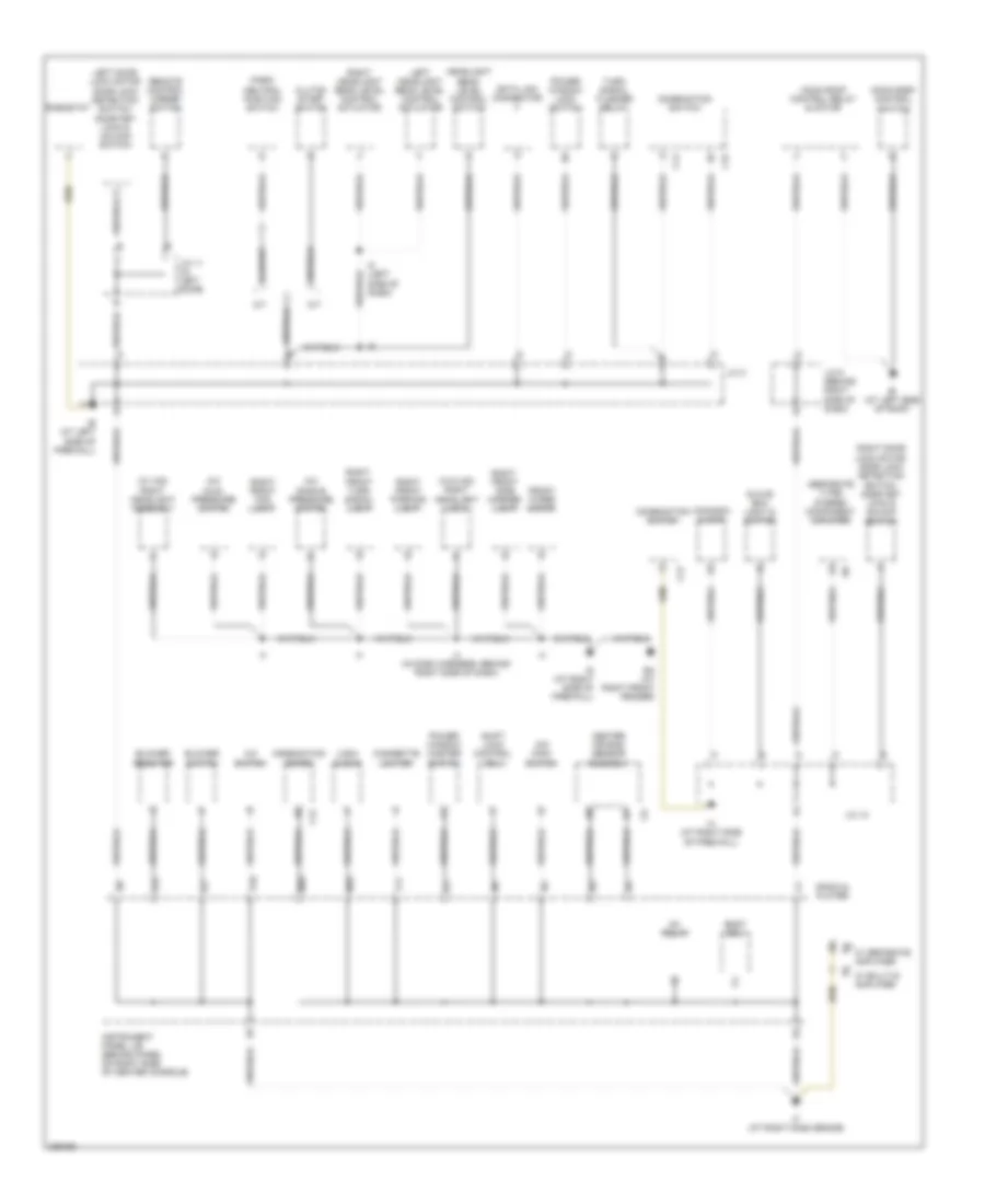
Ground Distribution Wiring Diagram, GT-S (2 of 2) for Toyota Celica GT 2005
 https://portal-diagnostov.com/license.html
Automotive Electricians Portal FZCO
Automotive Electricians Portal FZCO
https://portal-diagnostov.com/license.html
https://portal-diagnostov.com/license.html
Automotive Electricians Portal FZCO
Automotive Electricians Portal FZCOList of elements for Ground Distribution Wiring Diagram, GT-S (2 of 2) for Toyota Celica GT 2005:
- (canada) clock
- (separate type) stereo component amplifier
- (usa) clock
- (w/ hid) right headlight assembly
- (w/o hid) right headlight (low)
- A/c dual pressure switch
- A/c single pressure switch
- A/c switch
- A/t
- Bi (at left side of roof)
- Blower resistor
- Blower switch
- Body ecu
- C12
- C14
- C15
- Center air bag sensor assembly
- Cigarette lighter
- Clutch start switch
- Combination meter
- Combination switch
- Data link connector
- Ea (at right front fender)
- F11
- Front wiper motor
- Glove box light & switch
- Headlight beam level control switch
- I12
- I4 (in dash harness, behind right side of dash)
- I5 (left side of dash)
- Ie (at left side of firewall)
- If (at right dash brace)
- Ig (at right side of firewall)
- Ig1 relay
- Ih (at right side of firewall)
- Instrument panel j/b (behind panel on right side of center console)
- J/c 10
- J/c 11 (in left door)
- J/c 3
- J/c 9 (behind right side of dash)
- Left door lock motor door lock detection switch, door key lock & unlock switch
- Left headlight beam level control actuator
- M/t
- M10
- M20
- Moon roof control relay & motor
- Moon roof control switch
- O/d main switch
- P17
- P18
- Park/ neutral position switch
- Power window lock switch
- Power window master switch
- Radio & player
- Remote control mirror switch
- Rheostat
- Right door lock motor, door lock detection switch, door key lock & unlock switch
- Right front fog light
- Right front parking light
- Right front side marker light
- Right front turn signal light
- Right headlight beam level control actuator
- Shift lock control ecu
- Turn signal flasher relay
- W/ built-in amplifier
- W/ separate amplifier
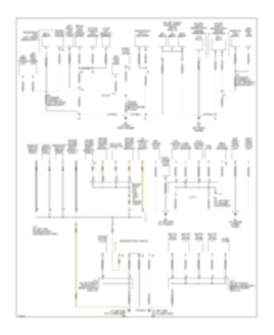
Ground Distribution Wiring Diagram, GT (1 of 2) for Toyota Celica GT 2005
 https://portal-diagnostov.com/license.html
Automotive Electricians Portal FZCO
Automotive Electricians Portal FZCO
https://portal-diagnostov.com/license.html
https://portal-diagnostov.com/license.html
Automotive Electricians Portal FZCO
Automotive Electricians Portal FZCOList of elements for Ground Distribution Wiring Diagram, GT (1 of 2) for Toyota Celica GT 2005:
- (at left side of cylinder head) ec
- (at left side of cylinder head) ed
- (in engine harness, at left center of engine compt)
- (on left side of engine compt) engine room j/b
- (on left side of engine compt) engine room r/b 1
- (on left side of engine compt) engine room r/b 2
- (w/ hid) left headlight assembly
- A/c magnetic clutch & lock sensor
- Auto antenna control relay
- Bj (at left side of luggage compartment)
- Bk (at left side of liftback)
- Bl (at center of rear panel)
- Brake fluid level warning switch
- C12
- Camshaft position sensor shield
- Combin- ation meter
- Crankshaft position sensor shield
- Data link connector
- Daytime running light resistor
- Door control receiver
- Drl 3 relay
- Drl 4 relay
- E1 (in engine harness, at left center of engine compt)
- Eb (at right front fender)
- Efi relay
- Em (at left front fender)
- Engine control module
- Engine room j/b (on left side of engine compt)
- Engine room r/b 2 (left side of engine compt)
- F13
- F25
- F26
- F27
- Fan 2 relay
- Fuel pump
- Heated oxygen sensor (bank 1 sensor 1)
- Heated oxygen sensor (bank 1 sensor 1) shield
- Heated oxygen sensor (bank 1 sensor 2)
- Heated oxygen sensor (bank 1 sensor 2) shield
- High mounted stop light
- Htr relay
- I1 (in dash harness, behind center of dash)
- Idle air control valve
- Ig2 relay
- Ignition coil & igniter
- J/c 1 (on left side of engine compt, forward of battery)
- J/c 14
- J/c 2 (on left side of engine compartment, beneath engine room j/b)
- J/c 2 (on left side of engine compt, beneath engine room j/b)
- Knock sensor (bank 1) shield
- Left front fog light
- Left front parking light
- Left front side marker light
- Left front turn signal light
- Left head- light (low)
- Left license plate light
- Left rear combi- nation light
- Nca
- Noise filter
- R11
- Radiator fan motor
- Rear window defogger
- Right license plate light
- Right rear combi- nation light
- Skid control ecu w/ actuator
- W/o hid
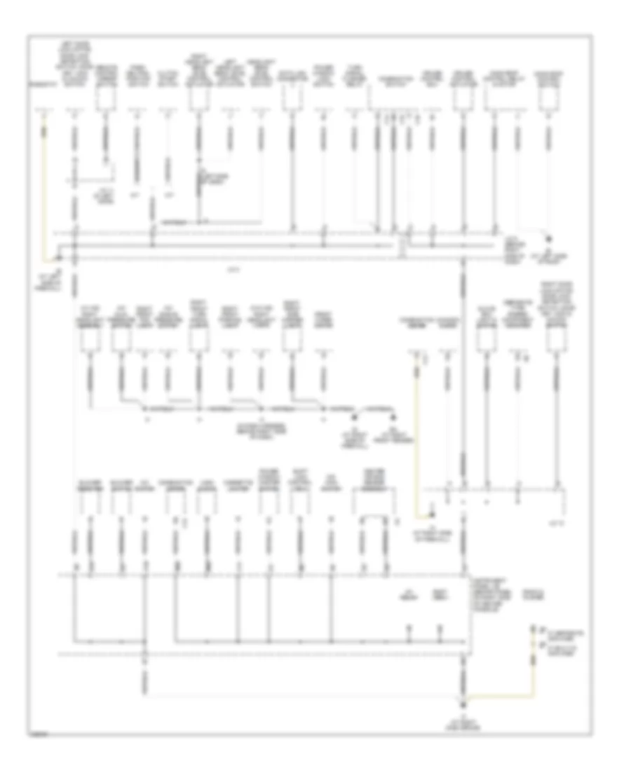
Ground Distribution Wiring Diagram, GT (2 of 2) for Toyota Celica GT 2005
 https://portal-diagnostov.com/license.html
Automotive Electricians Portal FZCO
Automotive Electricians Portal FZCO
https://portal-diagnostov.com/license.html
https://portal-diagnostov.com/license.html
Automotive Electricians Portal FZCO
Automotive Electricians Portal FZCOList of elements for Ground Distribution Wiring Diagram, GT (2 of 2) for Toyota Celica GT 2005:
- (canada) clock
- (separate type) stereo component amplifier
- (usa) clock
- (w/ hid) right headlight assembly
- (w/o hid) right headlight (low)
- A/c dual pressure switch
- A/c single pressure switch
- A/c switch
- A/t
- Bi (at left side of roof)
- Blower resistor
- Blower switch
- Body ecu
- C12
- C14
- C15
- C16
- Center air bag sensor assembly
- Cigarette lighter
- Clutch start switch
- Combination meter
- Combination switch
- Cruise control actuator
- Cruise control ecu
- Data link connector
- Ea (at right front fender)
- F11
- Front wiper motor
- Glove box light & switch
- Headlight beam level control switch
- I12
- I4 (in dash harness, behind right side of dash)
- Ie (at left side of firewall)
- If (at right dash brace)
- Ig (at right side of firewall)
- Ig1 relay
- Ih (at right side of firewall)
- Instrument panel j/b (behind panel on right side of center console)
- J/c 10
- J/c 11 (in left door)
- J/c 3
- J/c 9 (behind right side of dash)
- Left door lock motor, door lock detection switch, door key lock & unlock switch
- Left headlight beam level control actuator
- M/t
- M10
- M20
- Moon roof control relay & motor
- Moon roof control switch
- O/d main switch
- Of dash)
- P17
- P18
- Park/ neutral position switch
- Power window lock switch
- Power window master switch
- Radio & player
- Remote control mirror switch
- Rheostat
- Right door lock motor, door lock detection switch, door key lock & unlock switch
- Right front fog light
- Right front parking light
- Right front side marker light
- Right front turn signal light
- Right headlight beam level control actuator
- Shift lock control ecu
- Turn signal flasher relay
- W/ built-in amplifier
- W/ separate amplifier
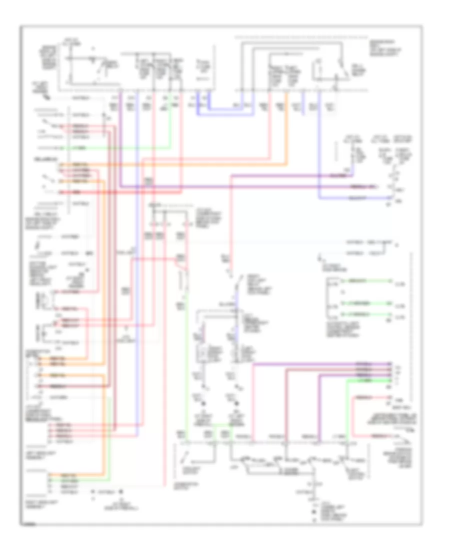
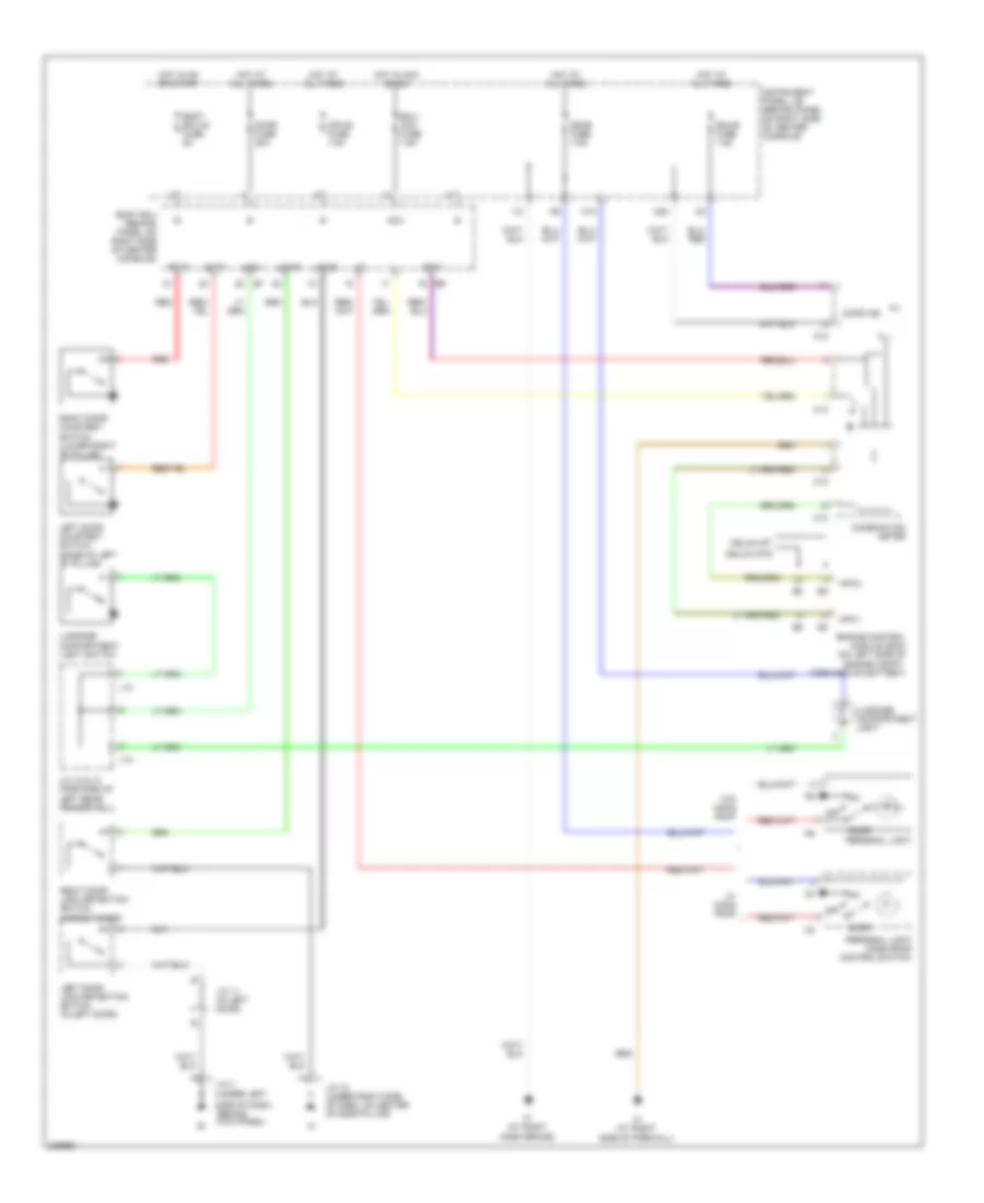
HEADLIGHTS
Headlights Wiring Diagram, with High Intensity Gas Discharge Headlights for Toyota Celica GT 2005
 https://portal-diagnostov.com/license.html
Automotive Electricians Portal FZCO
Automotive Electricians Portal FZCO
https://portal-diagnostov.com/license.html
https://portal-diagnostov.com/license.html
Automotive Electricians Portal FZCO
Automotive Electricians Portal FZCOList of elements for Headlights Wiring Diagram, with High Intensity Gas Discharge Headlights for Toyota Celica GT 2005:
- (at left front fender) em
- (behind left kick panel)
- Automatic light control sensor (under front center of dash)
- Beam ind
- Body ecu
- Body ecu-ig fuse 5a
- C12
- C13
- C15
- Cltb
- Clte
- Clts
- Combination meter
- Combination switch
- D10
- Daytime running light resistor (behind left front headlight)
- Dimmer switch
- Drl
- Drl 2 dimmer relay
- Drl 3 relay
- Drl 4 relay
- Eb (at right front fender)
- Em (at left front fender)
- Engine room j/b (on left side of engine compt)
- Engine room r/b 2 (on left side of engine compt)
- F17
- F20
- Flash
- Foglight switch
- Fr fog fuse 15a
- Front fog light relay
- Head
- Head fuse 10a
- Head ind
- Head relay
- Head- lvl drl 1 fuse 7.5a
- High
- Hot at all times
- Hot in on or start
- Hrly
- I12
- If (at right dash brace)
- Ig (at right side of firewall)
- Instrument panel j/b (behind panel on right side of center console)
- J/c 3 (under left side of dash, behind kick panel)
- J/c 4 & 5 (under right side of dash, behind kick panel)
- J/c 7 (behind upper right center of dash)
- Left front fog light
- Left headlight assembly
- Left lower head fuse 15a
- Left upper
- Light control switch
- Low
- M20
- Main fuse 40a
- Mpx- b fuse 7.5a
- Off
- Parking brake switch (on base of park brake lever)
- Pkb
- Red
- Right front fog light
- Right headlight assembly
- Right lower head fuse 15a
- Right upper
- Tail
- W/ fog light
- W/o fog light
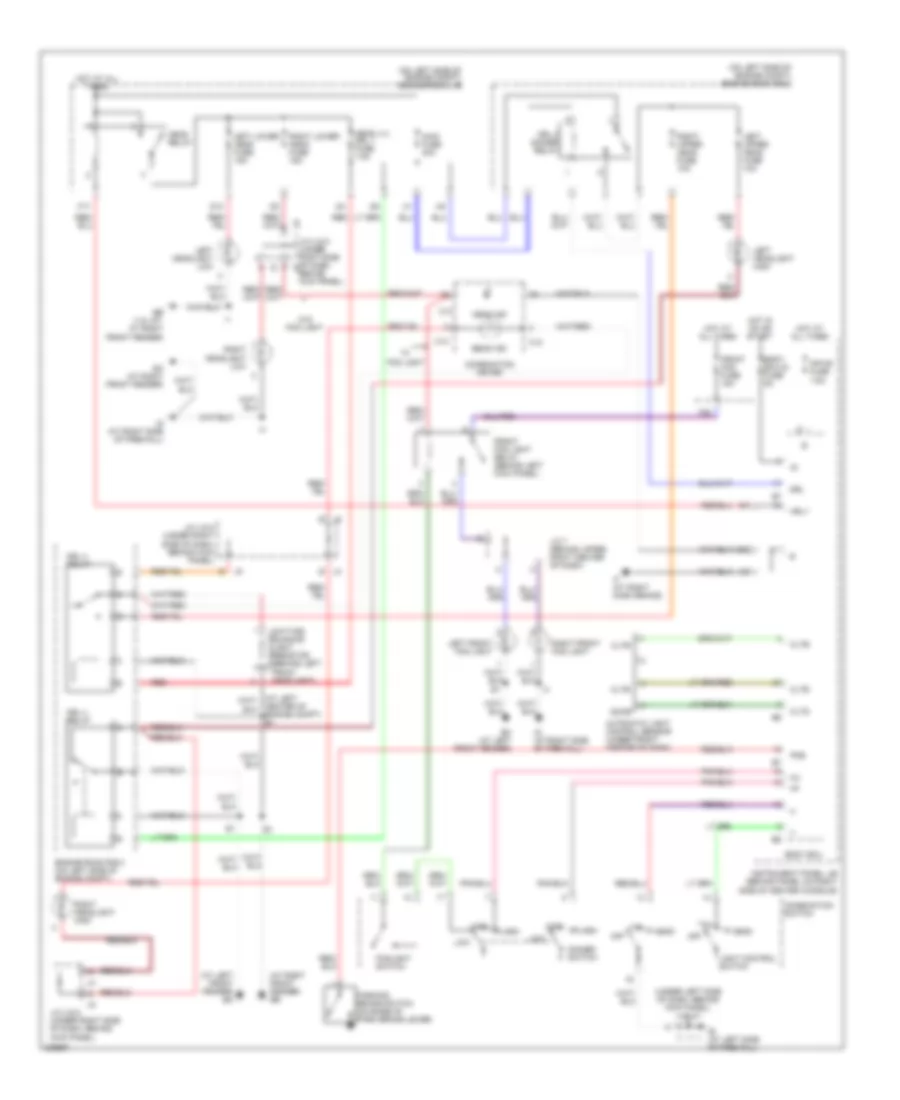
Headlights Wiring Diagram, without High Intensity Gas Discharge Headlights for Toyota Celica GT 2005
 https://portal-diagnostov.com/license.html
Automotive Electricians Portal FZCO
Automotive Electricians Portal FZCO
https://portal-diagnostov.com/license.html
https://portal-diagnostov.com/license.html
Automotive Electricians Portal FZCO
Automotive Electricians Portal FZCOList of elements for Headlights Wiring Diagram, without High Intensity Gas Discharge Headlights for Toyota Celica GT 2005:
- (at left front fender) em
- (at right front fender) eb
- (on left side of engine compt) engine room j/b
- (on left side of engine compt) engine room r/b 2
- (under left side of dash, behind kick panel) j/c 3
- Automatic light control sensor (under front center of dash)
- Beam ind
- Body ecu
- Body ecu-ig fuse 5a
- C12
- C13
- Center of engine compt) e1
- Cltb
- Clte
- Clts
- Combination meter
- Combination switch
- D10
- Daytime running light resistor (behind left front headlight)
- Dimmer switch
- Drl
- Drl 2 dimmer relay
- Drl 3 relay
- Drl 4 relay
- Ea (at right front fender)
- Eb (1.8l gt: at right front fender)
- Em (at left front fender)
- Engine room r/b 2 (on left side of engine compt)
- F17
- F20
- Flash
- Fog light
- Foglight switch
- Front fog fuse 15a
- Front fog light relay (behind left kick panel)
- Head
- Head ind
- Head lvl drl 1 fuse 7.5a
- Head relay
- High
- Hot at all times
- Hot in on or start
- Hrly
- I12
- Ie (at left side of firewall)
- If (at right dash brace)
- Ig (at right side of firewall)
- Instrument panel j/b (behind panel on right side of center console)
- J/c 4 & 5 (under right side of dash, behind j5 kick panel)
- J/c 4 & 5 (under right side of dash, behind kick panel)
- J/c 7 (behind upper right center of dash)
- Left front fog light
- Left headlight high
- Left headlight low
- Left lower head fuse 15a
- Left upper head fuse 10a
- Light control switch
- Low
- M20
- Main fuse 40a
- Mpx-b fuse 7.5a
- Off
- Parking brake switch (on base of park brake lever)
- Pkb
- Red
- Right front fog light
- Right headlight high
- Right headlight low
- Right lower head fuse 15a
- Right upper head fuse 10a
- Tail
- W/o fog light
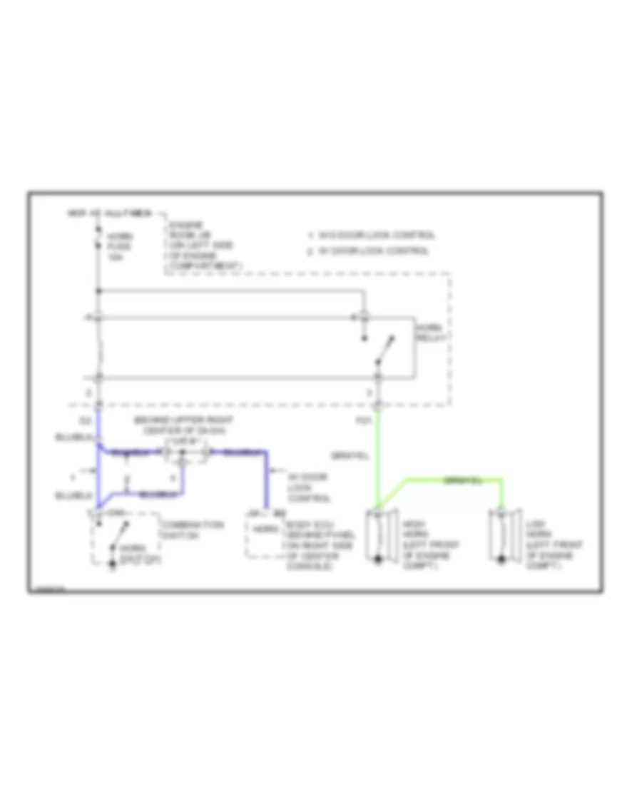
HORN
Horn Wiring Diagram for Toyota Celica GT 2005
 https://portal-diagnostov.com/license.html
Automotive Electricians Portal FZCO
Automotive Electricians Portal FZCO
https://portal-diagnostov.com/license.html
https://portal-diagnostov.com/license.html
Automotive Electricians Portal FZCO
Automotive Electricians Portal FZCOList of elements for Horn Wiring Diagram for Toyota Celica GT 2005:
- (behind upper right center of dash) j/c 8
- Body ecu (behind panel on right side of center console)
- C16
- Combination switch
- Engine room j/b (on left side of engine compartment)
- F21
- High horn (left front of engine compt)
- Horn
- Horn fuse 10a
- Horn relay
- Horn switch
- Hot at all times
- Low horn (left front of engine compt)
- W/ door lock control
- W/o door lock control
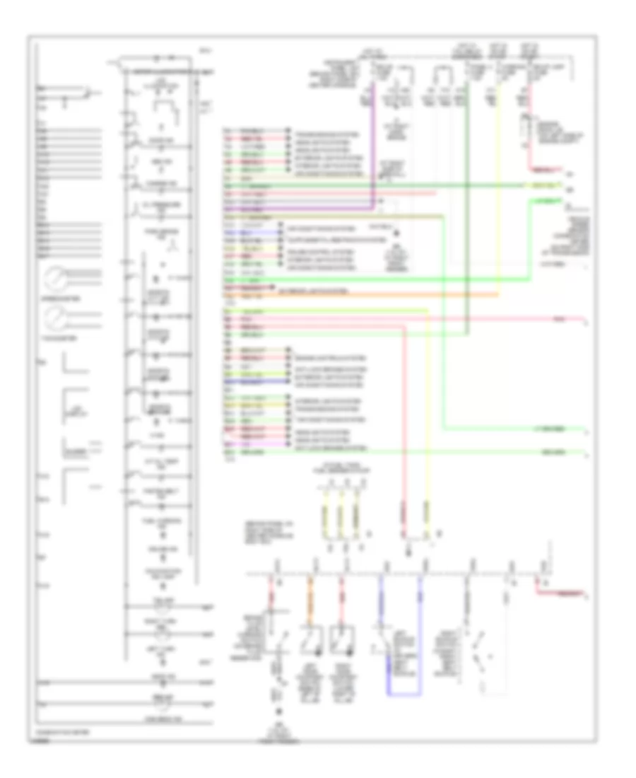
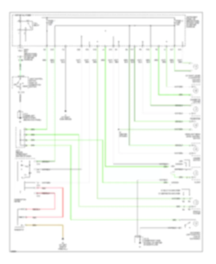
INSTRUMENT CLUSTER
Instrument Cluster Wiring Diagram (1 of 2) for Toyota Celica GT 2005
 https://portal-diagnostov.com/license.html
Automotive Electricians Portal FZCO
Automotive Electricians Portal FZCO
https://portal-diagnostov.com/license.html
https://portal-diagnostov.com/license.html
Automotive Electricians Portal FZCO
Automotive Electricians Portal FZCOList of elements for Instrument Cluster Wiring Diagram (1 of 2) for Toyota Celica GT 2005:
- (at right side of firewall)
- (behind panel on right side of center console) body ecu
- (in fuel tank) fuel sender & pump
- A/t oil temp ind
- A10
- A11
- A12
- A13
- A14
- A15
- A16
- A17
- A18
- A19
- A20
- A21
- A22
- Abs ind
- Air conditioning system
- Anti-lock brakes system
- B10
- B11
- B12
- B13
- B14
- B15
- B16
- B17
- B18
- Bk/up lamp fuse 5a
- Blvl
- Brake fluid level warning switch (on brake fluid reservoir)
- Buzzer
- C12
- C13
- Charge ind
- Combination meter
- Cruise control system
- Cruise ind
- Dbkl
- Dcty
- Door ind
- Eb (1.8l gt: at right front fender)
- Ecu-b fuse 7.5a
- Engine controls system
- Engine room j/b (on left side of engine compt)
- Exterior lights system
- F10
- Fasten belt ind
- Fu+
- Fu-
- Fua
- Fuel warning ind
- Head ind
- Headlights system
- High beam ind
- Hot at all times
- Hot in on or start
- Hot w/ tail relay energized
- I12
- If (at right dash brace)
- Ig+
- Instrument panel j/b (behind panel on right side of center console)
- Interior lights system
- Lcd display
- Lcd illumination
- Left buckle switch (in driver's
- Left door courtesy switch (base of left "b" pillar)
- Left turn ind
- M ind
- M11
- M19
- M20
- Malfunction ind lamp
- Meter illumination
- Mpx1
- Oil pressure ind
- Panel 2 fuse 7.5a
- Park brake ind
- Pbkl
- Pcty
- Pkb
- Pnk
- Red
- Right buckle switch (in right front seat belt buckle)
- Right door courtesy switch (lower right "b" pillar)
- Right turn ind
- Seat belt buckle)
- Sg2
- Sg3
- Speedometer
- Sports a/t1 ind
- Sports a/t2 ind
- Sports a/t3 ind
- Sports a/t4 ind
- Srs ind
- Tachometer
- Tail ind
- Transmissions system
- Vehicle speed sensor (combination meter) (on right side of transmission)
- Warning fuse 5a
Instrument Cluster Wiring Diagram (2 of 2) for Toyota Celica GT 2005
 https://portal-diagnostov.com/license.html
Automotive Electricians Portal FZCO
Automotive Electricians Portal FZCO
https://portal-diagnostov.com/license.html
https://portal-diagnostov.com/license.html
Automotive Electricians Portal FZCO
Automotive Electricians Portal FZCOList of elements for Instrument Cluster Wiring Diagram (2 of 2) for Toyota Celica GT 2005:
- (canada) clock
- (usa) clock
- Acc
- Ambient temperature sensor (left front of engine compt)
- Canada
- Dome fuse 7.5a
- Earth
- Ecu-acc fuse 7.5a
- Engine control module (ecm) (on left side of engine compt, forward of battery)
- Except gt w/ cruise control
- Gt w/ cruise control
- Gt-s
- Hot at all times
- Hot in acc or on
- Hot in on or start
- I12
- I2 (canada)
- I3 (canada)
- If (at right dash brace)
- Ig+
- Instrument panel j/b (behind panel on right side of center console)
- Junction connector 10 (under right side of dash, on center of door pillar)
- Junction connector 6 (behind upper left center of dash)
- Junction connector 8 (behind upper right center of dash)
- M10
- M17 (usa)
- M2 (usa)
- Mops
- Mpx1
- Mpx2
- Oil pressure switch (1.8l gt-s: on left side of engine, below intake manifold) (wtl: top rear of engine)
- Oil pressure switch (on left side of engine, below intake manifold) (wtl: top rear of engine)
- Osw
- Parking brake switch (on base of park brake lever)
- Pbew
- Pnk
- Psw
- Skid control ecu with ecu with actuator actuator (left rear of engine compt)
- Spd
- Tens rdc fuse 5a
- Th+
- Usa
INTERIOR LIGHTS
Courtesy Lamps Wiring Diagram for Toyota Celica GT 2005
 https://portal-diagnostov.com/license.html
Automotive Electricians Portal FZCO
Automotive Electricians Portal FZCO
https://portal-diagnostov.com/license.html
https://portal-diagnostov.com/license.html
Automotive Electricians Portal FZCO
Automotive Electricians Portal FZCOList of elements for Courtesy Lamps Wiring Diagram for Toyota Celica GT 2005:
- (under left
- Acc
- Body ecu (behind panel on right side of center console)
- Body ecu-ig fuse 5a
- C12
- C13
- Celica gt
- Celica gts
- Combination meter
- Dcty
- Dome fuse 7.5a
- Door
- Door fuse 20a
- Door ind
- Ecu- acc fuse 7.5a
- Ecu-b fuse 7.5a
- Engine control module (ecm) (on left side of engine compt, forward of battery)
- Hot at all times
- Hot in acc or on
- Hot in on or start
- I12
- If (at right dash brace)
- Ih (at right side of firewall)
- Instrument panel j/b (behind panel on right side of center console)
- J/c 10 (under right side of dash, on center of door pillar)
- J/c 11 (in left door)
- J/c 12 & 13 (forward of left rear fenderwell)
- J/c 3
- J12
- J13
- Left door courtesy switch (base of left "b" pillar)
- Left door lock detection switch (in left door)
- Lgcy
- Lswd
- Lswp
- Luggage compartment light
- Luggage compartment light switch
- M20
- Mpx-b fuse 7.5a
- Mpx1
- Mpx2
- N13
- Off
- Pcty
- Personal light
- Personal light (moon roof control switch)
- Red
- Right door courtesy switch (lower right "b" pillar)
- Right door lock detection switch (in right door)
- Side of dash, behind kick panel)
- W/ moon roof
- W/o moon roof
Instrument Illumination Wiring Diagram for Toyota Celica GT 2005
 https://portal-diagnostov.com/license.html
Automotive Electricians Portal FZCO
Automotive Electricians Portal FZCO
https://portal-diagnostov.com/license.html
https://portal-diagnostov.com/license.html
Automotive Electricians Portal FZCO
Automotive Electricians Portal FZCOList of elements for Instrument Illumination Wiring Diagram for Toyota Celica GT 2005:
- A/c switch
- A/t shift lever illumination (o/d main switch)
- Body ecu (behind panel on right side of center console)
- C12
- C13
- C15
- Canada
- Cigarette lighter
- Clock
- Combination meter
- F17
- Glove box light & switch (top of glove box)
- Hazard switch
- Head
- Headlight beam level control switch
- Hot at all times
- I12
- I6 (center of dash)
- Ie (at left side of firewall)
- If (at right dash brace)
- Ill
- Instrument panel j/b (behind panel on right side of center console)
- J/c 10 (under right side of dash, on center of door pillar)
- J/c 3 (under left side of dash, behind kick panel)
- J/c 8 (behind upper right center of dash)
- Light control switch (part of combination switch)
- M10
- M16
- M18
- M19
- M20
- N10
- N17
- Off
- P16
- Panel 1 fuse 7.5a
- Panel 2 fuse 7.5a
- Radio & player
- Red
- Rheostat
- Tail
- Tail relay
- Trly
- Usa
- W/ built-in amplifier
- W/ separate amplifier
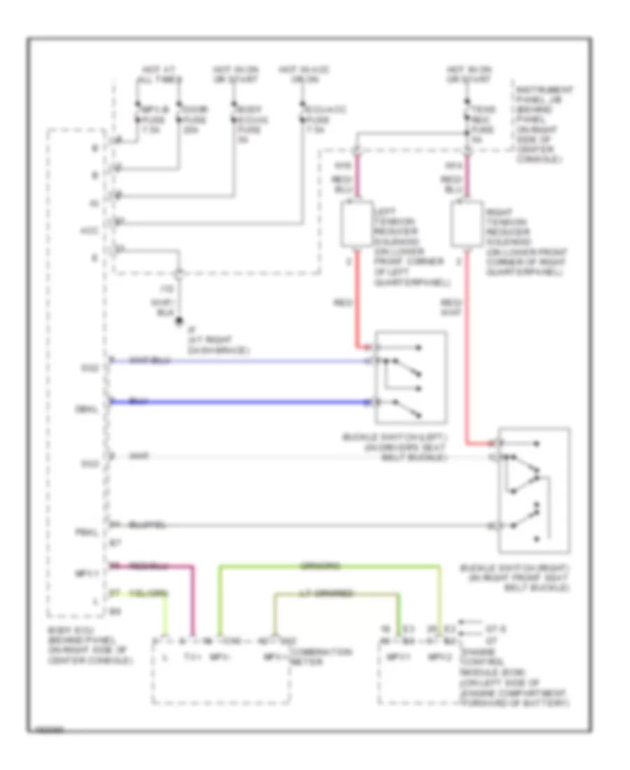
PASSIVE RESTRAINTS
Passive Restraints Wiring Diagram for Toyota Celica GT 2005
 https://portal-diagnostov.com/license.html
Automotive Electricians Portal FZCO
Automotive Electricians Portal FZCO
https://portal-diagnostov.com/license.html
https://portal-diagnostov.com/license.html
Automotive Electricians Portal FZCO
Automotive Electricians Portal FZCOList of elements for Passive Restraints Wiring Diagram for Toyota Celica GT 2005:
- Acc
- Body ecu (behind panel on right side of center console)
- Body ecu-ig fuse 5a
- Buckle switch (left) (in driver's seat belt buckle)
- Buckle switch (right) (in right front seat belt buckle)
- C12
- C13
- Combination meter
- Dbkl
- Door fuse 20a
- Ecu-acc fuse 7.5a
- Engine control module (ecm) (on left side of engine compartment, forward of battery)
- Gt-s
- Hot at all times
- Hot in acc or on
- Hot in on or start
- I12
- If (at right dash brace)
- Instrument panel j/b (behind panel on right side of center console)
- Left tension reducer solenoid (on lower front corner of left quarterpanel)
- Mpx+
- Mpx-
- Mpx-b fuse 7.5a
- Mpx1
- Mpx2
- N14
- N16
- Pbkl
- Red
- Right tension reducer solenoid (on lower front corner of right quarterpanel)
- Sg2
- Sg3
- Tens rdc fuse 5a
- Tx+
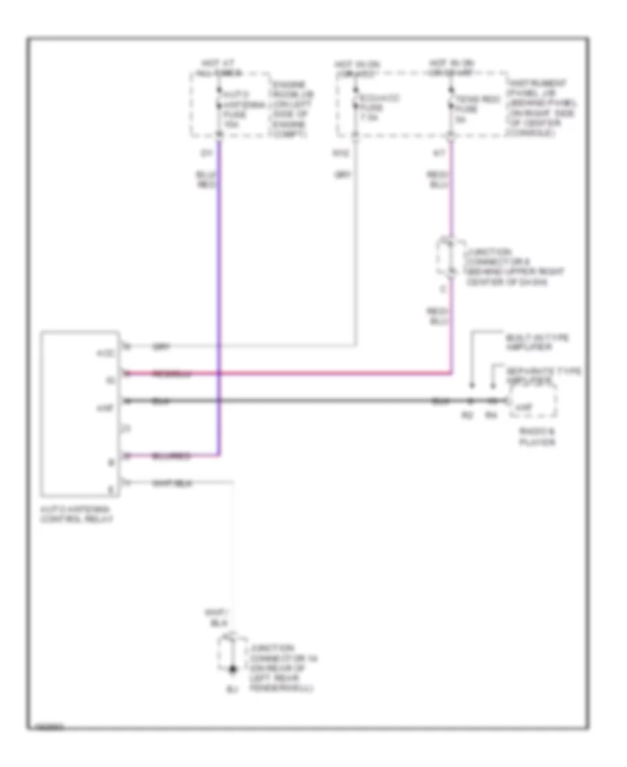
POWER ANTENNA
Power Antenna Wiring Diagram for Toyota Celica GT 2005
 https://portal-diagnostov.com/license.html
Automotive Electricians Portal FZCO
Automotive Electricians Portal FZCO
https://portal-diagnostov.com/license.html
https://portal-diagnostov.com/license.html
Automotive Electricians Portal FZCO
Automotive Electricians Portal FZCOList of elements for Power Antenna Wiring Diagram for Toyota Celica GT 2005:
- Acc
- Ant
- Auto antenna control relay
- Auto antenna fuse 15a
- Built-in type amplifier
- Ecu-acc fuse 7.5a
- Engine room j/b (on left side of engine compt)
- Hot at all times
- Hot in on or acc
- Hot in on or start
- Instrument panel j/b (behind panel on right side of center console)
- Junction connector 14 (on rear of left rear fenderwell)
- Junction connector 8 (behind upper right center of dash)
- N12
- Radio & player
- Separate type amplifier
- Tens rdc fuse 5a
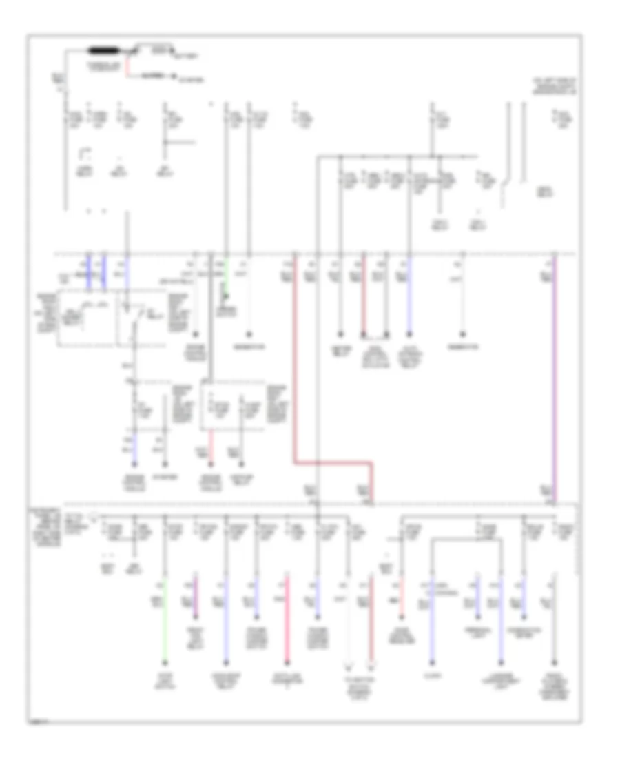
POWER DISTRIBUTION
Power Distribution Wiring Diagram (1 of 2) for Toyota Celica GT 2005
 https://portal-diagnostov.com/license.html
Automotive Electricians Portal FZCO
Automotive Electricians Portal FZCO
https://portal-diagnostov.com/license.html
https://portal-diagnostov.com/license.html
Automotive Electricians Portal FZCO
Automotive Electricians Portal FZCOList of elements for Power Distribution Wiring Diagram (1 of 2) for Toyota Celica GT 2005:
- (1.8l gt-s)
- (diagram 2 of 2)
- (on left side of engine compt) engine room j/b
- A-amp fuse 50a
- Abs 1 fuse 50a
- Abs 2 fuse 25a
- Air-pump relay
- Alt fuse 120a
- Alt-s fuse 7.5a
- Am1 fuse 25a
- Am2 fuse 7.5a
- Auto antenna control relay
- Auto antenna fuse 15a
- Battery
- Body ecu
- Cds fuse 30a
- Clock
- Combination meter
- Data link connector
- Dcc fuse 25a
- Def fuse 30a
- Def relay
- Dome fuse 7.5a
- Door control receiver
- Door fuse 20a
- Drl 2 dimmer relay
- Ecu-b fuse 7.5a
- Efi fuse 20a
- Efi relay
- Engine control module
- Engine room j/b (on left side of engine compt)
- Engine room r/b 1 (on left side of engine compt)
- Engine room r/b 2 (on left side of eng compt)
- Etcs fuse 10a
- F16
- F20
- F29
- Fan 1 relay
- Fan 3 relay
- Fl p/w fuse 20a
- Fr fog fuse 15a
- Fr p/w fuse 20a
- Front fog light relay
- Generator
- Haz fuse 10a
- Hazard switch
- Head relay
- Heater relay
- Horn fuse 10a
- Horn relay
- Htr fuse 50a
- I3 (canada)
- Ig2 fuse 15a
- Ig2 relay
- Instrument panel j/b to tail relay (behind panel on right side of center console)
- K11
- Luggage compartment light
- M17 (usa)
- Main fuse 40a
- Moon roof control relay
- Mpx-b fuse 7.5a
- N13
- Nca
- Obd fuse 7.5a
- Personal light
- Pnk
- Power window master switch
- Radio fuse 15a
- Radio, player & stereo component amplifier
- Rdi fuse 30a
- Red
- S/roof fuse 15a
- Skid control ecu with actuator
- St fuse 7.5a
- St relay
- Starter
- Stop fuse 10a
- Stop light switch
- Switch (diagram 2 of 2)
- To ignition
- W/o hid
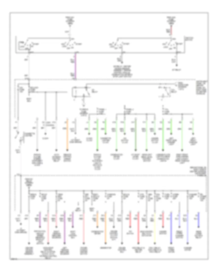
Power Distribution Wiring Diagram (2 of 2) for Toyota Celica GT 2005
 https://portal-diagnostov.com/license.html
Automotive Electricians Portal FZCO
Automotive Electricians Portal FZCO
https://portal-diagnostov.com/license.html
https://portal-diagnostov.com/license.html
Automotive Electricians Portal FZCO
Automotive Electricians Portal FZCOList of elements for Power Distribution Wiring Diagram (2 of 2) for Toyota Celica GT 2005:
- (behind panel on right side of center console) instrument panel j/b
- A/c switch
- A/c switch (illum)
- A/t shift lever (illum)
- Abs- ig fuse 5a
- Acc
- Am1
- Am2
- Auto antenna control relay
- B13
- Bk/up lamp fuse 5a
- Body ecu
- Body ecu-ig fuse 5a
- Center air bag sensor assembly
- Cig fuse 15a
- Cigarette lighter
- Cigarette lighter (illum)
- Clock
- Clock (illum)
- Combination meter
- Combination meter (illum)
- Cruise control clutch switch (m/t)
- Cruise control ecu
- Def relay
- Def rly fuse 5a
- E10
- Ecu-acc fuse 7.5a
- Ecu-ig fuse 5a
- F11
- F17
- Fan 1 relay, fan 2 relay & fan 3 relay
- Fan rly fuse 5a
- From am1 fuse (diagram 1 of 2)
- From am2 fuse (diagram 1 of 2)
- From door fuse (diagram 1 of 2)
- From ig1 relay (diagram 2 of 2)
- Front wiper motor
- Front wiper/ washer switch
- Generator
- H10
- Hazard switch
- Hazard switch (illum)
- Headlight beam level control switch
- Htr fuse 10a
- I10
- I12
- I2 (canada)
- If (at right dash brace)
- Ig1
- Ig1 relay
- Ig2
- Ig2 relay, center air bag sensor assembly, engine control module, combination meter & stop light switch
- Ignition switch
- Instrument panel j/b (behind panel on right side of center console)
- K10
- K12
- Left front parking light
- Left front side marker light
- Left tension reducer solenoid
- License plate lights & rear combination lights
- Lock
- M11
- M19
- M2 (usa)
- Mg/c relay & heater relay
- Moon roof control relay & motor, clock, auto antenna control relay
- N11
- N12
- N14
- N16
- N17
- Off
- P16
- Panel 1 fuse 7.5a
- Panel 2 fuse 7.5a
- Pnp switch, vehicle speed sensor & back-up light switch
- Power window master switch
- Radio & player (illum), glove box light & switch & clock (illum)
- Radio & player, stereo component amplifier & clock
- Rear wiper motor & relay
- Red
- Remote control mirror switch
- Right front side marker light & right front parking light
- Right tension reducer solenoid
- Rr wiper fuse 15a
- Shift lock control ecu
- Skid control ecu with actuator
- Srs-ig fuse 7.5a
- St relay
- St2
- Start
- Tail fuse 10a
- Tail relay
- Tens rdc fuse 5a
- To srs-ig fuse (diagram 2 of 2)
- Turn fuse 7.5a
- Warning fuse 5a
- Washer fuse 15a
- Washer motor
- Wiper fuse 25a
POWER DOOR LOCKS
Power Door Locks Wiring Diagram, with Keyless Entry for Toyota Celica GT 2005
 https://portal-diagnostov.com/license.html
Automotive Electricians Portal FZCO
Automotive Electricians Portal FZCO
https://portal-diagnostov.com/license.html
https://portal-diagnostov.com/license.html
Automotive Electricians Portal FZCO
Automotive Electricians Portal FZCOList of elements for Power Door Locks Wiring Diagram, with Keyless Entry for Toyota Celica GT 2005:
- Acc
- Act+
- Act-
- Actd
- Back door lock motor (on rear of liftback)
- Body ecu
- Body ecu-ig fuse 5a
- C12
- C13
- Combination meter
- Dcty
- Door control receiver (behind trim panel, above left rear fenderwell)
- Door fuse 20a
- Door lock control switch (power window master switch)
- Ecu-acc fuse 7.5a
- Engine control module (ecm) (on left side of engine compt, forward of battery)
- Gnd
- Gts
- Horn
- Horns system
- Hot at all times
- Hot in acc or on
- Hot in on or start
- I12
- If (at right dash brace)
- Instrument panel j/b (behind panel on right side of center console)
- Interior lights system
- Junction connector 10 (under right side of dash, on center of door pillar)
- Junction connector 11 (in left door)
- Junction connector 14 (on rear of left rear fenderwell)
- Junction connector 3 (under left side of dash, behind kick panel)
- Ksw
- Left door courtesy switch (base of left "b" pillar)
- Left door lock motor, door lock detection switch & door key lock & unlock switch (in left door)
- Lgcy
- Lock
- Lswd
- Lswp
- Mpx+
- Mpx-
- Mpx-b fuse 7.5a
- Mpx1
- Mpx2
- Pcty
- Prg
- Rda
- Red
- Right door courtesy switch (lower right "b" pillar)
- Right door lock motor, door lock detection switch & door key lock & unlock switch (in right door)
- Sg1
- Tx+
- Ul1
- Ul2
- Ul3
- Unlk
- Unlock warning switch (under left side of dash)
Power Door Locks Wiring Diagram, without Keyless Entry for Toyota Celica GT 2005
 https://portal-diagnostov.com/license.html
Automotive Electricians Portal FZCO
Automotive Electricians Portal FZCO
https://portal-diagnostov.com/license.html
https://portal-diagnostov.com/license.html
Automotive Electricians Portal FZCO
Automotive Electricians Portal FZCOList of elements for Power Door Locks Wiring Diagram, without Keyless Entry for Toyota Celica GT 2005:
- Acc
- Act+
- Act-
- Actd
- Back door lock motor (on rear of liftback)
- Body ecu
- Body ecu-ig fuse 5a
- C12
- C13
- Combination meter
- Dcty
- Door fuse 20a
- Door lock control switch (power window master switch)
- Ecu-acc fuse 7.5a
- Engine control module (ecm) (on left side of engine compt, forward of battery)
- Gt gts
- Hot at all times
- Hot in acc or on
- Hot in on or start
- I12
- If (at right dash brace)
- Instrument panel j/b (behind panel on right side of center console)
- Junction connector 10 (under right side of dash, on center of door pillar)
- Junction connector 11 (in left door)
- Junction connector 3 (under left side of dash, behind kick panel)
- Ksw
- Left door courtesy switch (base of left "b" pillar)
- Left door lock motor, door lock detection switch & door key lock & unlock switch (in left door)
- Lock
- Lswd
- Lswp
- Mpx+
- Mpx-
- Mpx-b fuse 7.5a
- Mpx1
- Mpx2
- Pcty
- Red
- Right door courtesy switch (lower right "b" pillar)
- Right door lock motor, door lock detection switch & door key lock & unlock switch (in right door)
- Sg1
- Tx+
- Ul1
- Ul2
- Ul3
- Unlk
- Unlock warning switch (under left side of dash)
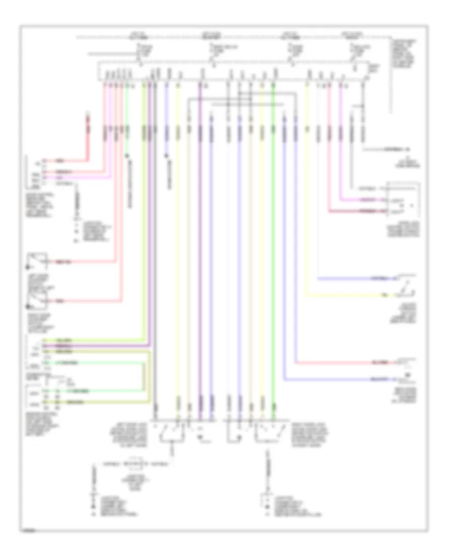
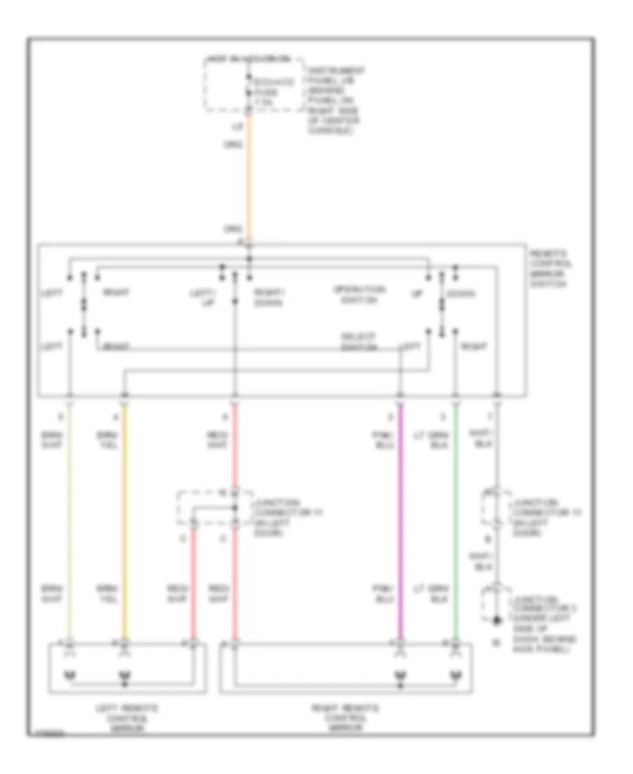
POWER MIRRORS
Power Mirrors Wiring Diagram for Toyota Celica GT 2005
 https://portal-diagnostov.com/license.html
Automotive Electricians Portal FZCO
Automotive Electricians Portal FZCO
https://portal-diagnostov.com/license.html
https://portal-diagnostov.com/license.html
Automotive Electricians Portal FZCO
Automotive Electricians Portal FZCOList of elements for Power Mirrors Wiring Diagram for Toyota Celica GT 2005:
- Down
- Ecu-acc fuse 7.5a
- Hot in acc or on
- Instrument panel j/b (behind panel on right side of center console)
- Junction connector 11 (in left door)
- Junction connector 3 (under left side of dash, behind kick panel)
- Left
- Left remote control mirror
- Left/ up
- Operation switch
- Remote control mirror switch
- Right
- Right remote control mirror
- Right/ down
- Select switch
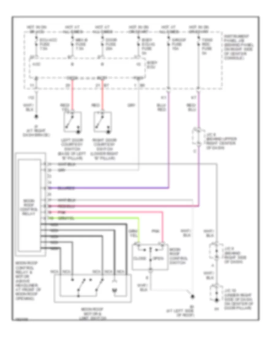
POWER TOP/SUNROOF
Power Top/Sunroof Wiring Diagram for Toyota Celica GT 2005
 https://portal-diagnostov.com/license.html
Automotive Electricians Portal FZCO
Automotive Electricians Portal FZCO
https://portal-diagnostov.com/license.html
https://portal-diagnostov.com/license.html
Automotive Electricians Portal FZCO
Automotive Electricians Portal FZCOList of elements for Power Top/Sunroof Wiring Diagram for Toyota Celica GT 2005:
- Acc
- Bi (at left side of roof)
- Body ecu
- Body ecu-ig fuse 5a
- Close
- Dcty
- Door fuse 20a
- Ecu-acc fuse 7.5a
- Hot at all times
- Hot in on or acc
- Hot in on or start
- I12
- If (at right dash brace)
- Instrument panel j/b (behind panel on right side of center console)
- J/c 10 (under right side of dash, on center of door pillar)
- J/c 8 (behind upper right center of dash)
- J/c 9 (behind right side of dash)
- Left door courtesy switch (base of left "b" pillar)
- Mbx-b fuse 7.5a
- Moon roof control switch
- Moon roof motor & limit switch
- Moon roof control relay
- Moon roof control relay & motor (above headliner, at front of moon roof opening)
- Nca
- Open
- Pcty
- Pnk
- Pws
- Red
- Right door courtesy switch (lower right "b" pillar)
- S/roof fuse 15a
- Tens rdc fuse 5a
POWER WINDOWS
Power Windows Wiring Diagram for Toyota Celica GT 2005
 https://portal-diagnostov.com/license.html
Automotive Electricians Portal FZCO
Automotive Electricians Portal FZCO
https://portal-diagnostov.com/license.html
https://portal-diagnostov.com/license.html
Automotive Electricians Portal FZCO
Automotive Electricians Portal FZCOList of elements for Power Windows Wiring Diagram for Toyota Celica GT 2005:
- Acc
- Bdr
- Body ecu (behind panel on right side of center console)
- Body ecu-ig fuse 5a
- Dcty
- Def rly fuse 5a
- Door fuse 20a
- Ecu-acc fuse 7.5a
- Fl p/w fuse 20a
- Fr p/w fuse 20a
- Hot at all times
- Hot in acc or on
- Hot in on or start
- I12
- If (at right dash brace)
- Instrument panel j/b (behind panel on right side of center console)
- Junction connector 3 (under left side of dash, behind kick panel)
- Kof
- Left door courtesy switch (base of left "b" pillar)
- Left power window motor (in left door)
- Mpx-b fuse 7.5a
- N11
- P/w
- Pcty
- Power window lock switch
- Power window master switch
- Red
- Right door courtesy switch (lower right "b" pillar)
- Right power window motor (in right door)
- W/l
RADIO
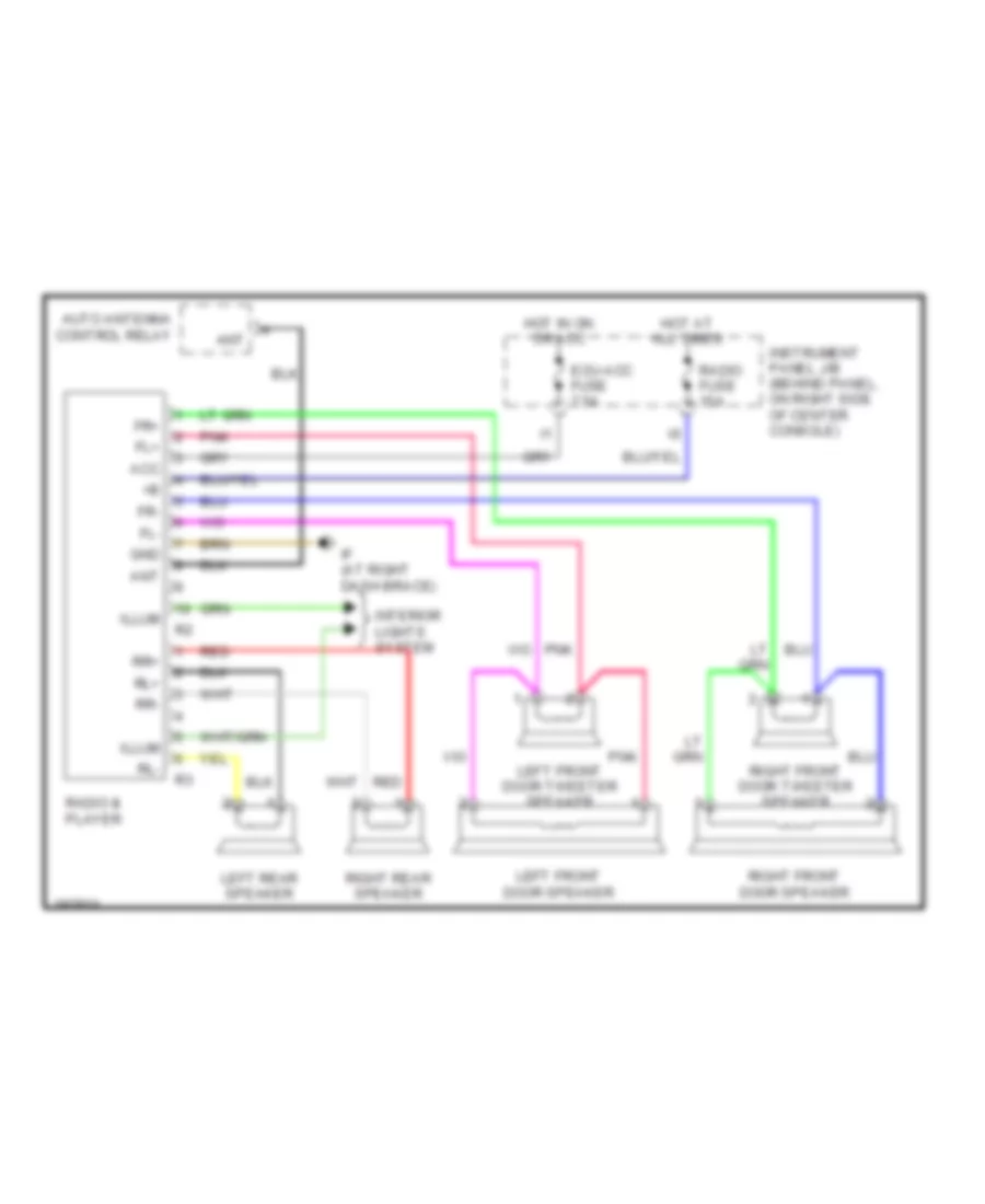
Radio Wiring Diagram, with Built-in Amplifier for Toyota Celica GT 2005
 https://portal-diagnostov.com/license.html
Automotive Electricians Portal FZCO
Automotive Electricians Portal FZCO
https://portal-diagnostov.com/license.html
https://portal-diagnostov.com/license.html
Automotive Electricians Portal FZCO
Automotive Electricians Portal FZCOList of elements for Radio Wiring Diagram, with Built-in Amplifier for Toyota Celica GT 2005:
- Acc
- Ant
- Auto antenna control relay
- Ecu-acc fuse 7.5a
- Fl+
- Fl-
- Fr+
- Fr-
- Gnd
- Hot at all times
- Hot in on or acc
- If (at right dash brace)
- Illum
- Instrument panel j/b (behind panel, on right side of center console)
- Interior lights system
- Left front door speaker
- Left front door tweeter speaker
- Left rear speaker
- Pnk
- Radio & player
- Radio fuse 15a
- Red
- Right front door speaker
- Right front door tweeter speaker
- Right rear speaker
- Rl+
- Rl-
- Rr+
- Rr-
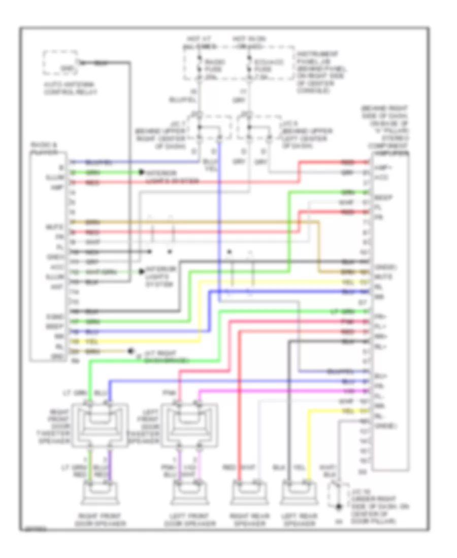
Radio Wiring Diagram, with Separate Amplifier for Toyota Celica GT 2005
 https://portal-diagnostov.com/license.html
Automotive Electricians Portal FZCO
Automotive Electricians Portal FZCO
https://portal-diagnostov.com/license.html
https://portal-diagnostov.com/license.html
Automotive Electricians Portal FZCO
Automotive Electricians Portal FZCOList of elements for Radio Wiring Diagram, with Separate Amplifier for Toyota Celica GT 2005:
- (at right dash brace)
- (behind right side of dash, on base of "a" pillar) stereo component amplifier
- Acc
- Amp
- Amp+
- Ant
- Auto antenna control relay
- Beep
- Bu+
- Ecu-acc fuse 7.5a
- Fl+
- Fl-
- Fr+
- Fr-
- Gnd
- Gnd(e)
- Gnd(s)
- Gnd3
- Hot at all times
- Hot in on or acc
- Illum
- Instrument panel j/b (behind panel, on right side of center console)
- Interior lights system
- J/c 10 (under right side of dash, on center of door pillar)
- J/c 6 (behind upper left center of dash)
- J/c 7 (behind upper right center of dash)
- Left front door speaker
- Left front door tweeter speaker
- Left rear speaker
- Mute
- Nca
- Pnk
- Radio & player
- Radio fuse 15a
- Red
- Right front door speaker
- Right front door tweeter speaker
- Right rear speaker
- Rl+
- Rl-
- Rr+
- Rr-
- Sgnd
SHIFT INTERLOCK
Shift Interlock Wiring Diagram for Toyota Celica GT 2005
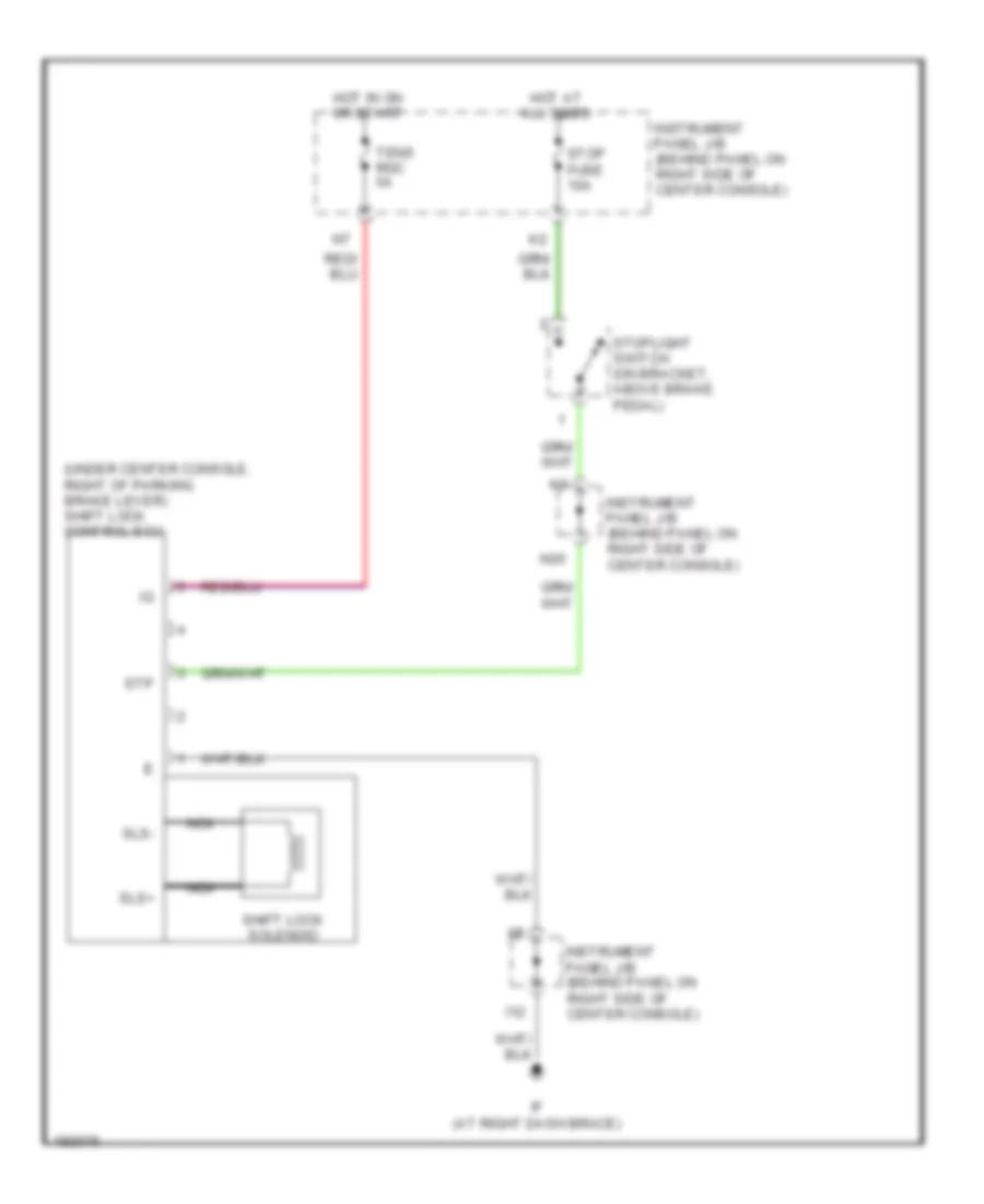 https://portal-diagnostov.com/license.html
Automotive Electricians Portal FZCO
Automotive Electricians Portal FZCO
https://portal-diagnostov.com/license.html
https://portal-diagnostov.com/license.html
Automotive Electricians Portal FZCO
Automotive Electricians Portal FZCOList of elements for Shift Interlock Wiring Diagram for Toyota Celica GT 2005:
- (under center console, right of parking brake lever) shift lock control ecu
- Hot at all times
- Hot in on or start
- I12
- If (at right dash brace)
- Instrument panel j/b (behind panel on right side of center console)
- N20
- Nca
- Shift lock solenoid
- Sls+
- Sls-
- Stop fuse 10a
- Stoplight switch (on bracket, above brake pedal)
- Stp
- Tens rdc 5a
STARTING/CHARGING
Charging Wiring Diagram for Toyota Celica GT 2005
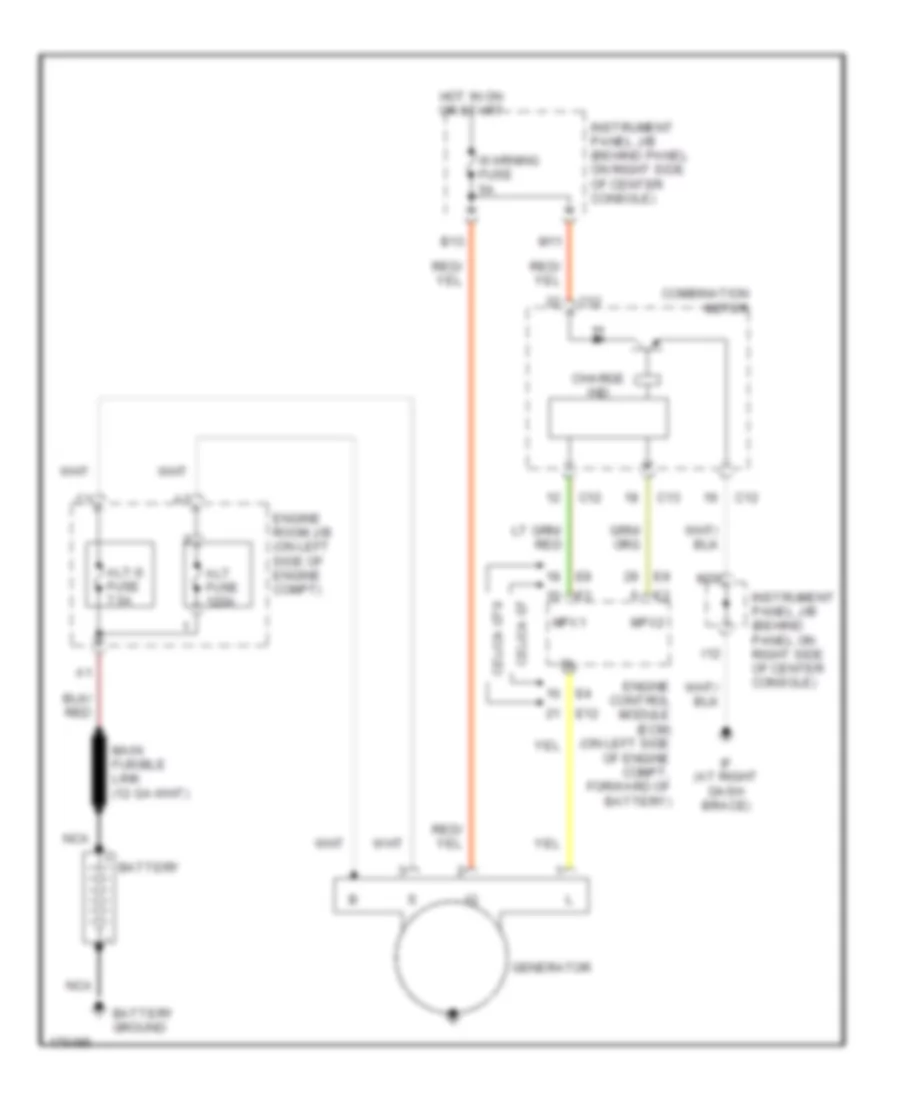 https://portal-diagnostov.com/license.html
Automotive Electricians Portal FZCO
Automotive Electricians Portal FZCO
https://portal-diagnostov.com/license.html
https://portal-diagnostov.com/license.html
Automotive Electricians Portal FZCO
Automotive Electricians Portal FZCOList of elements for Charging Wiring Diagram for Toyota Celica GT 2005:
- Alt fuse 120a
- Alt-s fuse 7.5a
- B13
- Battery
- Battery ground
- C12
- C13
- Celica gt
- Celica gts
- Charge ind
- Combination meter
- E12
- Engine control module (ecm) (on left side of engine compt, forward of battery)
- Engine room j/b (on left side of engine compt)
- Generator
- Hot in on or start
- I12
- If (at right dash brace)
- Instrument panel j/b (behind panel on right side of center console)
- M11
- M20
- Mpx1
- Mpx2
- Nca
- Warning fuse 5a
Starting Wiring Diagram for Toyota Celica GT 2005
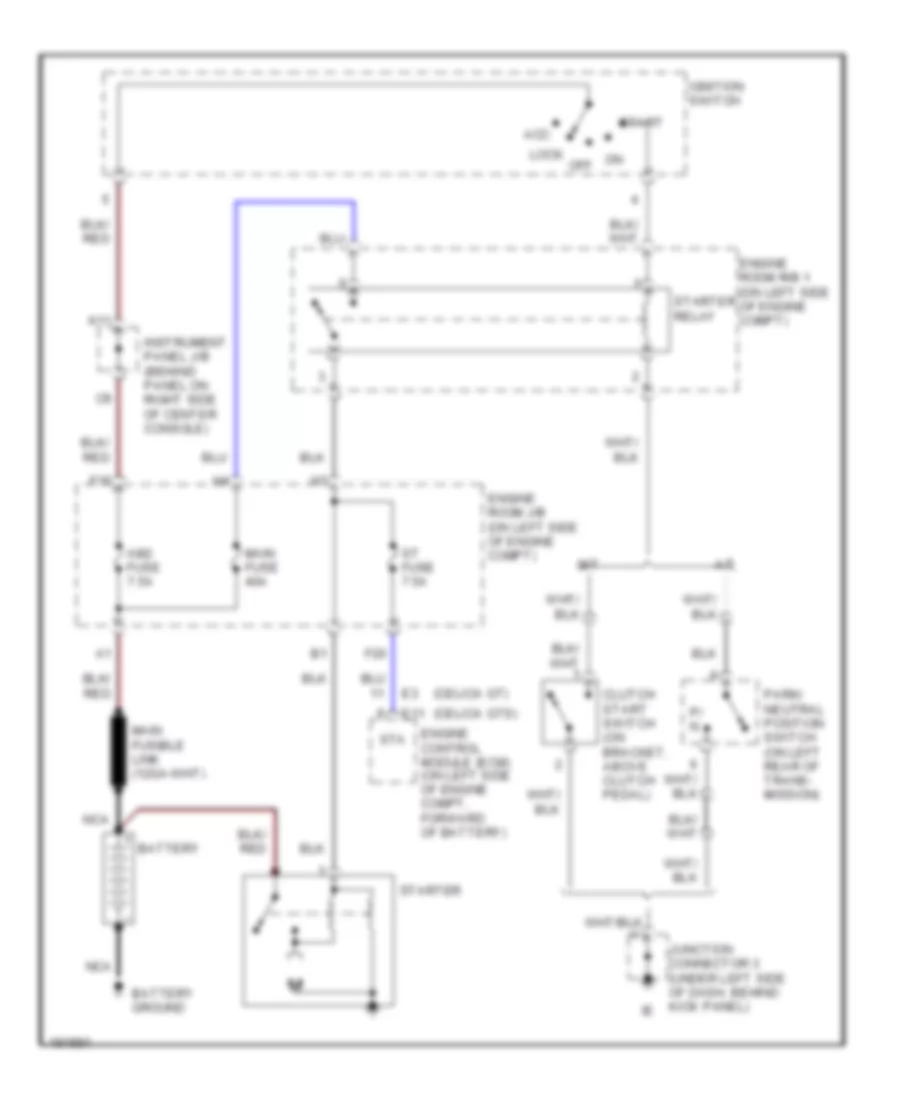 https://portal-diagnostov.com/license.html
Automotive Electricians Portal FZCO
Automotive Electricians Portal FZCO
https://portal-diagnostov.com/license.html
https://portal-diagnostov.com/license.html
Automotive Electricians Portal FZCO
Automotive Electricians Portal FZCOList of elements for Starting Wiring Diagram for Toyota Celica GT 2005:
- (celica gt)
- (celica gts)
- A/t
- Acc
- Am2 fuse 7.5a
- Battery
- Battery ground
- Clutch start switch (on bracket, above clutch pedal)
- E11
- Engine control module (ecm) (on left side of engine compt, forward of battery)
- Engine room j/b (on left side of engine compt)
- Engine room r/b 1 (on left side of engine compt)
- F16
- F20
- Ignition switch
- Instrument panel j/b (behind panel on right side of center console)
- Junction connector 3 (under left side of dash, behind kick panel)
- K11
- Lock
- M/t
- Main fuse 40a
- Nca
- Off
- P/ n
- Park/ neutral position switch (on left rear of trans- mission)
- St fuse 7.5a
- Sta
- Start
- Starter
- Starter relay
SUPPLEMENTAL RESTRAINTS
Supplemental Restraints Wiring Diagram for Toyota Celica GT 2005
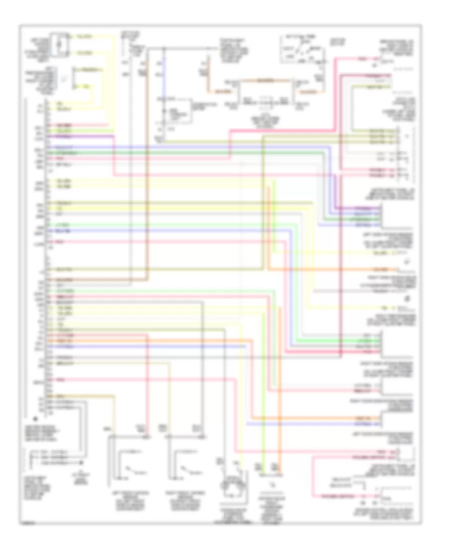 https://portal-diagnostov.com/license.html
Automotive Electricians Portal FZCO
Automotive Electricians Portal FZCO
https://portal-diagnostov.com/license.html
https://portal-diagnostov.com/license.html
Automotive Electricians Portal FZCO
Automotive Electricians Portal FZCOList of elements for Supplemental Restraints Wiring Diagram for Toyota Celica GT 2005:
- (behind panel on right side of center console) body ecu
- +sl
- +sr
- -sl
- -sr
- Acc
- Air bag squib (front passenger air bag assembly) (right side of dash)
- Air bag squib (steering wheel pad) (in steering wheel)
- Am2
- B14
- Bltw
- C12
- Celica gt
- Celica gts
- Center air bag sensor assembly (behind lower center of dash)
- Combination meter
- Data link connector (dlc) 3 (under left side of dash, near kick panel)
- Dml+
- Dml-
- Dmr+
- Dmr-
- Engine control module (ecm) (on left side of engine compt, forward of battery)
- Esl
- Esr
- F/ps
- F18
- Fsl
- Fsr
- Gsw2
- H10
- Hot at all times
- Hot in on or start
- I12
- If (at right dash brace)
- Ig1
- Ig2
- Ignition switch
- Instrument panel j/b (behind panel on right side of center console)
- J/c 6 (behind upper left center of dash)
- Lbe+
- Left door side air bag sensor (if equipped) (inside door)
- Left front air bag sensor (on left front side of engine compartment)
- Left pretensioner (on lower front corner of left quarter panel)
- Left side air bag sensor (if equipped) (on lower front corner of left quarter panel)
- Left side air bag squib (if equipped) (in driver's seat)
- Lock
- Off
- Pl+
- Pl-
- Pnk
- Pr+
- Pr-
- Right door side air bag sensor (if equipped) (inside door)
- Right front air bag sensor (on right front side of engine compartment)
- Right pretensioner (on lower front corner of right quarter panel)
- Right side air bag sensor (if equipped) (on lower front corner of right quarter panel)
- Right side air bag squib (if equipped) (in passenger's front seat)
- Sfl+
- Sfl-
- Sfr+
- Sfr-
- Sil
- Spiral cable
- Srs warning light
- Srs-ig fuse 7.5a
- Ssl+
- Ssr+
- Start
- Vupl
- Vupr
TRANSMISSION
A/T Wiring Diagram, GT-S for Toyota Celica GT 2005
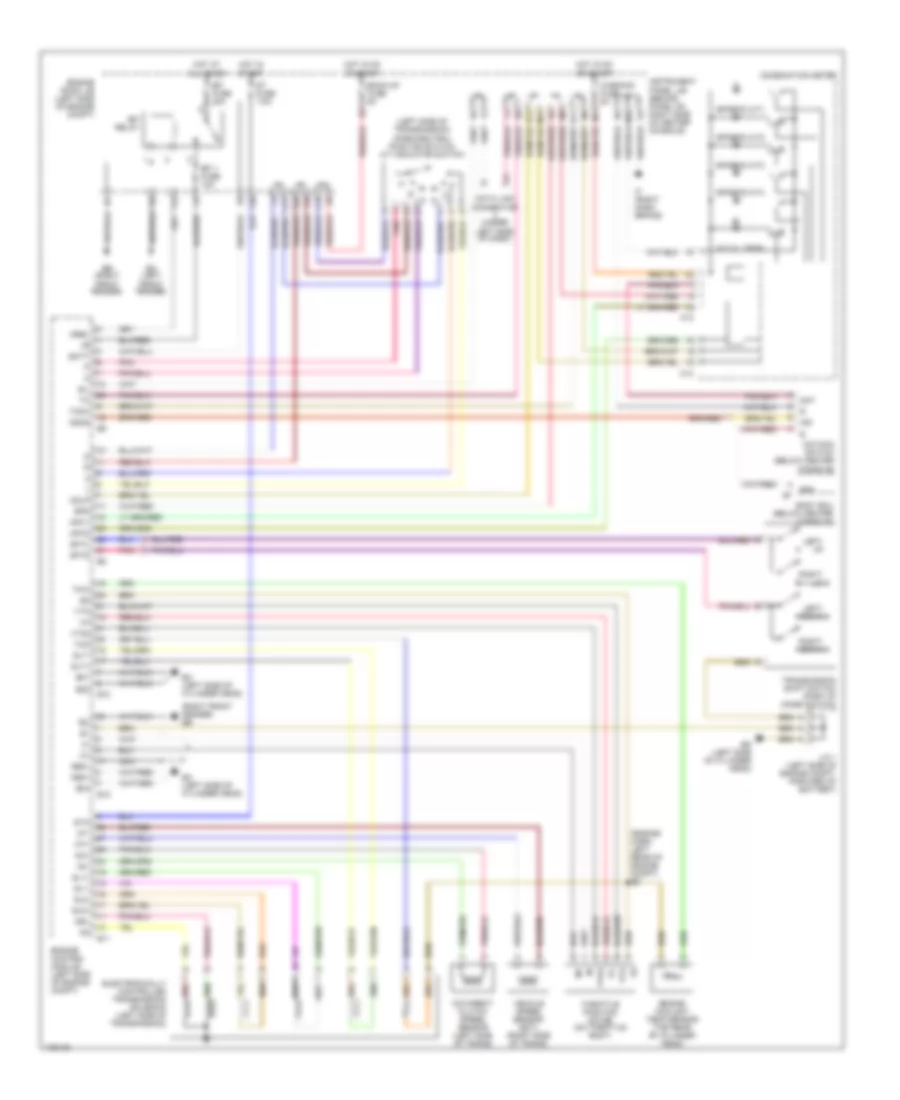 https://portal-diagnostov.com/license.html
Automotive Electricians Portal FZCO
Automotive Electricians Portal FZCO
https://portal-diagnostov.com/license.html
https://portal-diagnostov.com/license.html
Automotive Electricians Portal FZCO
Automotive Electricians Portal FZCOList of elements for A/T Wiring Diagram, GT-S for Toyota Celica GT 2005:
- (engine harn, left rear of engine compt) e2
- (left side of transmission) (park/neutral position switch) a/t indicator switch
- (right front fender) eb
- A/t oil temp
- B11
- B12
- Back-up fuse 5a
- Batt
- Body ecu (below center console)
- C12
- C13
- C17
- C19
- Combination meter
- Data link connector (under left side of dash)
- Dsl
- E01
- E02
- E03
- E10
- E11
- E12
- Eb (right front fender)
- Ec (left side of cylinder head)
- Ed (left side of cylinder head)
- Efi 1 fuse 10a
- Efi fuse 20a
- Efi relay
- Electronically controlled transmission solenoid (left side of transmission)
- Em (left front fender)
- Engine control module (left side of engine compt)
- Engine coolant temp sensor (top rear of cylinder head)
- Engine room j/b (left side of engine compt)
- F12
- F20
- F22
- Ge01
- Hot at all times
- Hot in on or start
- Hot in start
- I12
- If (right dash brace)
- Ind
- Instrument panel j/b (behind panel on right side of center console)
- J/c 1 (left side of engine compt, forward of battery)
- Left- down
- Left- up
- M11
- M12
- M20
- Me01
- Mpx1
- Mpx2
- Mrel
- Nc+
- Nc-
- Nca
- Nt+
- Nt-
- O/d direct clutch speed sensor (left side of trans)
- O/d main switch (below center console)
- Odlp
- Odms
- Pnk
- Red
- Right- down
- Right- up
- Sat
- Sftd
- Sftu
- Sg4
- Sil
- Sl1+
- Sl1-
- Sl2+
- Sl2-
- Slt+
- Slt-
- Spd
- Sports a/t1
- Sports a/t2
- Sports a/t3
- Sports a/t4
- St fuse 7.5a
- Sta
- Tach
- Tho
- Throttle position motor (on throttle body)
- Thw
- Transmission shift switch (part of combi switch)
- Vehicle speed sensor (ect) (right side of trans)
- Vta
- Vta2
- Warning fuse 5a
A/T Wiring Diagram, GT for Toyota Celica GT 2005
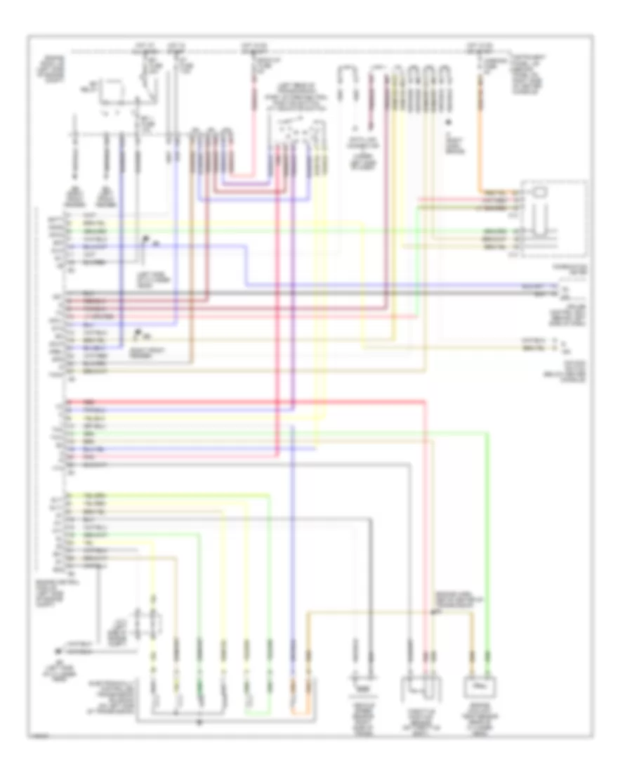 https://portal-diagnostov.com/license.html
Automotive Electricians Portal FZCO
Automotive Electricians Portal FZCO
https://portal-diagnostov.com/license.html
https://portal-diagnostov.com/license.html
Automotive Electricians Portal FZCO
Automotive Electricians Portal FZCOList of elements for A/T Wiring Diagram, GT for Toyota Celica GT 2005:
- (engine harn, above center of transmission e2
- (left rear of transmission) (part of park/neutral position switch) a/t indicator switch
- (left side of cylinder head)
- (right front fender)
- B11
- B12
- Back-up fuse 5a
- Batt
- C12
- C13
- C17
- C19
- Combination meter
- Cruise control ecu (behind left side of dash)
- Data link connector (under left side of dash)
- E01
- E02
- E03
- Eb (right front fender)
- Ed (left side of cylinder head)
- Efi 1 fuse 10a
- Efi fuse 20a
- Efi relay
- Electronically controlled transmission solenoid (on left side of transmission)
- Em (left front fender)
- Engine control module (left side of engine compt)
- Engine coolant temp sensor (rear of cylinder head)
- Engine room j/b (left side of engine compt)
- F12
- F20
- F22
- Hot at all times
- Hot in on or start
- Hot in start
- I12
- Idl
- Idlo
- If (right dash brace)
- Ind
- Instrument panel j/b (behind panel on right side of center console)
- J/c 2 (left side of engine compt)
- M11
- M12
- Mpx1
- Mpx2
- Mrel
- Nt+
- Nt-
- O/d main switch (below center console)
- Od1
- Odlp
- Odms
- Pnk
- Red
- Sil
- Slt+
- Slt-
- Spd
- St fuse 7.5a
- Sta
- Tach
- Tho
- Throttle position sensor (on throttle body)
- Thw
- Vehicle speed sensor (right side of trans)
- Vta
- Warning fuse 5a
WARNING SYSTEMS
Warning Systems Wiring Diagram for Toyota Celica GT 2005
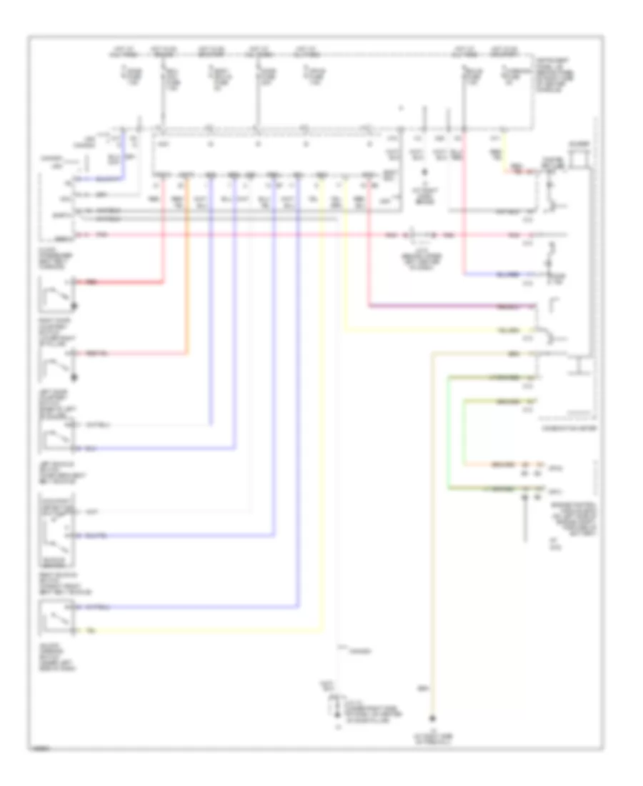 https://portal-diagnostov.com/license.html
Automotive Electricians Portal FZCO
Automotive Electricians Portal FZCO
https://portal-diagnostov.com/license.html
https://portal-diagnostov.com/license.html
Automotive Electricians Portal FZCO
Automotive Electricians Portal FZCOList of elements for Warning Systems Wiring Diagram for Toyota Celica GT 2005:
- Acc
- Body ecu
- Body ecu-ig fuse 5a
- Buckle switch
- Buzzer
- C12
- C13
- Canada
- Clock (passenger seat belt warning)
- Combination meter
- Dbkl
- Dcty
- Dome fuse 7.5a
- Door fuse 20a
- Door ind
- Earth
- Ecu- acc fuse 7.5a
- Ecu-b fuse 7.5a
- Engine control module (ecm) (on left side of engine compt, forward of battery)
- Fasten belt ind
- Gts
- Hot at all times
- Hot in on or acc
- Hot in on or start
- I12
- If (at right dash brace)
- Ih (at right side of firewall)
- Instrument panel j/b (behind panel on right side of center console)
- J/c 10 (under right side of dash, on center of door pillar)
- J/c 6 (behind upper left center of dash)
- Ksw
- Left buckle switch (in driver's seat belt buckle)
- Left door courtesy switch (base of left "b" pillar)
- M10
- M11
- M17
- M20
- Mpx-b fuse 7.5a
- Mpx1
- Mpx2
- Occupant detection switch
- Pbew
- Pbkl
- Pcty
- Pnk
- Red
- Right buckle switch (in right front seat belt buckle)
- Right door courtesy switch (lower right "b" pillar)
- Sg1
- Sg2
- Sg3
- Unlock warning switch (under left side of dash)
- Usa
- Warning fuse 5a
WIPER/WASHER
Front Wiper/Washer Wiring Diagram for Toyota Celica GT 2005
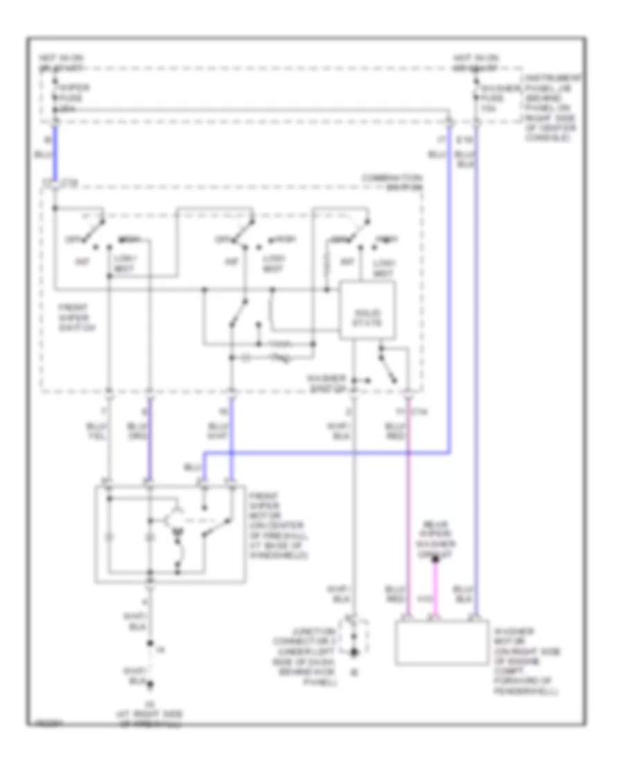 https://portal-diagnostov.com/license.html
Automotive Electricians Portal FZCO
Automotive Electricians Portal FZCO
https://portal-diagnostov.com/license.html
https://portal-diagnostov.com/license.html
Automotive Electricians Portal FZCO
Automotive Electricians Portal FZCOList of elements for Front Wiper/Washer Wiring Diagram for Toyota Celica GT 2005:
- C14
- Combination switch
- E10
- Front wiper motor (on center of firewall, at base of windshield)
- Front wiper switch
- High
- Hot in on or start
- Ig (at right side of firewall)
- Instrument panel j/b (behind panel on right side of center console)
- Int
- Junction connector 3 (under left side of dash, behind kick panel)
- Low/ mist
- Off
- Rear wiper/ washer circuit
- Solid state
- Washer fuse 15a
- Washer motor (on right side of engine compt, forward of fenderwell)
- Washer switch
- Wiper fuse 25a
Rear Wiper/Washer Wiring Diagram for Toyota Celica GT 2005
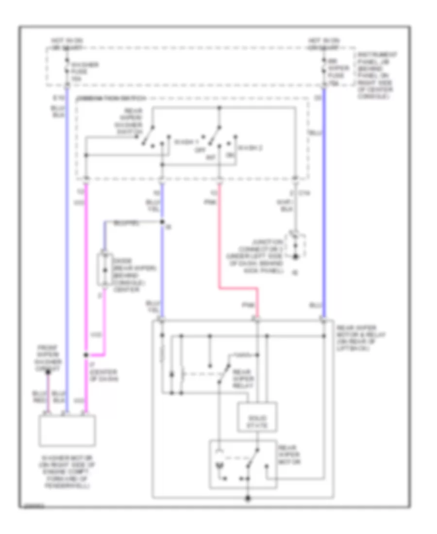 https://portal-diagnostov.com/license.html
Automotive Electricians Portal FZCO
Automotive Electricians Portal FZCO
https://portal-diagnostov.com/license.html
https://portal-diagnostov.com/license.html
Automotive Electricians Portal FZCO
Automotive Electricians Portal FZCOList of elements for Rear Wiper/Washer Wiring Diagram for Toyota Celica GT 2005:
- C14
- Combination switch
- Diode (rear wiper) (behind console) center
- E10
- Front wiper/ washer circuit
- Hot in on or start
- I7 (center of dash)
- Instrument panel j/b (behind panel on right side of center console)
- Int
- Junction connector 3 (under left side of dash, behind kick panel)
- Off
- Pnk
- Rear wiper motor
- Rear wiper motor & relay (on rear of liftback)
- Rear wiper relay
- Rear wiper/ washer switch
- Rr wiper fuse 15a
- Solid state
- Wash 1
- Wash 2
- Washer fuse 15a
- Washer motor (on right side of engine compt, forward of fenderwell)

 Čeština
 Dansk
Dansk Deutsch
 Ελληνικά
 English
 English
 Español
 Suomi
Suomi Français
 Français
 עברית
עברית Hrvatski
 Magyar
 Italiano
 한국어
한국어 Nederlands
 Polski
 Português
 Português
 Română
 Русский
 Slovenčina
 Slovenščina
 Svenska
 Türkçe
 中文 (中国)
