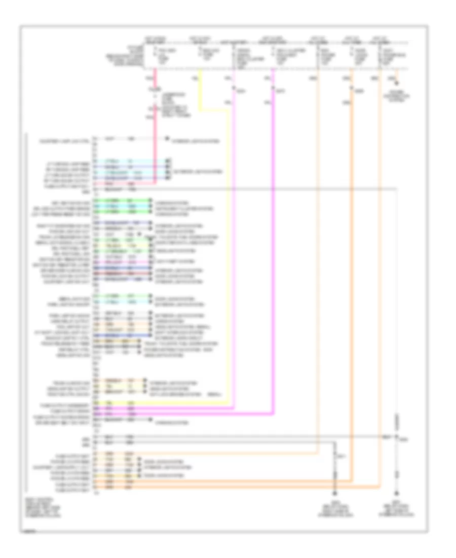
Автомтическая коробка Передач (АКПП) Полная привод (4WD) Блокировка Дифференциала
Электросхема автоматической коробки передач АКПП для Buick Regal GS 2004
 https://portal-diagnostov.com/license.html
Automotive Electricians Portal FZCO
Automotive Electricians Portal FZCO
https://portal-diagnostov.com/license.html
https://portal-diagnostov.com/license.html
Automotive Electricians Portal FZCO
Automotive Electricians Portal FZCO
Электросхема автоматической коробки передач АКПП для Buick Regal GS 2004 - Список элементов:
- (on transaxle right axle case extension) vehicle speed sensor
- 1-2 shift sol
- 2-3 shift sol
- A/t sensor hi
- A/t sensor lo
- Automatic transaxle
- Automatic transaxle fluid pressure manual valve position switch
- Automatic transaxle fluid temperature sensor
- Automatic transaxle input shaft speed sensor
- B12
- Battery in
- Bcm & instrument cluster
- Body control module & instrument cluster
- Brake switch in
- Cluster fuse 10a
- Data link connector (under left side of dash, right steering column)
- Ecm fuse 22 10a
- Ect return
- Ect sensor in
- Eng emis fuse 30 10a
- Engine controls system
- Engine coolant temperature sensor (top left side of eng, below throttle body)
- G113 (lower left front of engine on transaxle stud, left of starter)
- G113 (lower left front of engine, on transaxle stud, left of starter)
- Hot at all times
- Hot in off, run or start
- Hot in run or start
- Hot in run, bulb test or start
- I/p fuse block (behind right side of dash, in right door opening)
- Ign 0 fuse 10a
- Ignition (0) in
- Ignition (1) in
- Instrument panel cluster (ipc)
- Mil ctrl
- Pc sol hi
- Pc sol lo
- Pcm ground
- Pcm-bcm ign relay fuse 10a
- Pnk
- Powertrain control module (left side of engine compt, in air cleaner assembly)
- Pressure control sol
- Red
- S106
- S270
- Serial data
- Service engine soon
- Splice pack sp205 (near dlc)
- Stop lamp switch (on brake pedal support bracket)
- Tan
- Tcc pwm sol
- Tcc release
- Tcc release in
- Tcc/ brake switch
- Tft sensor gnd
- Tft sensor in
- Throttle position sensor (on throttle body)
- Tp 5v ref
- Tp sensor in
- Tps return
- Tr sw in-a
- Tr sw in-b
- Tr sw in-c
- Tr sw in-p
- Trans fuse 26 10a
- Transaxle internal mode switch
- Underhood fuse block (mounted to right front strut tower)
- Vss hi (signal)
- Vss lo (ground)
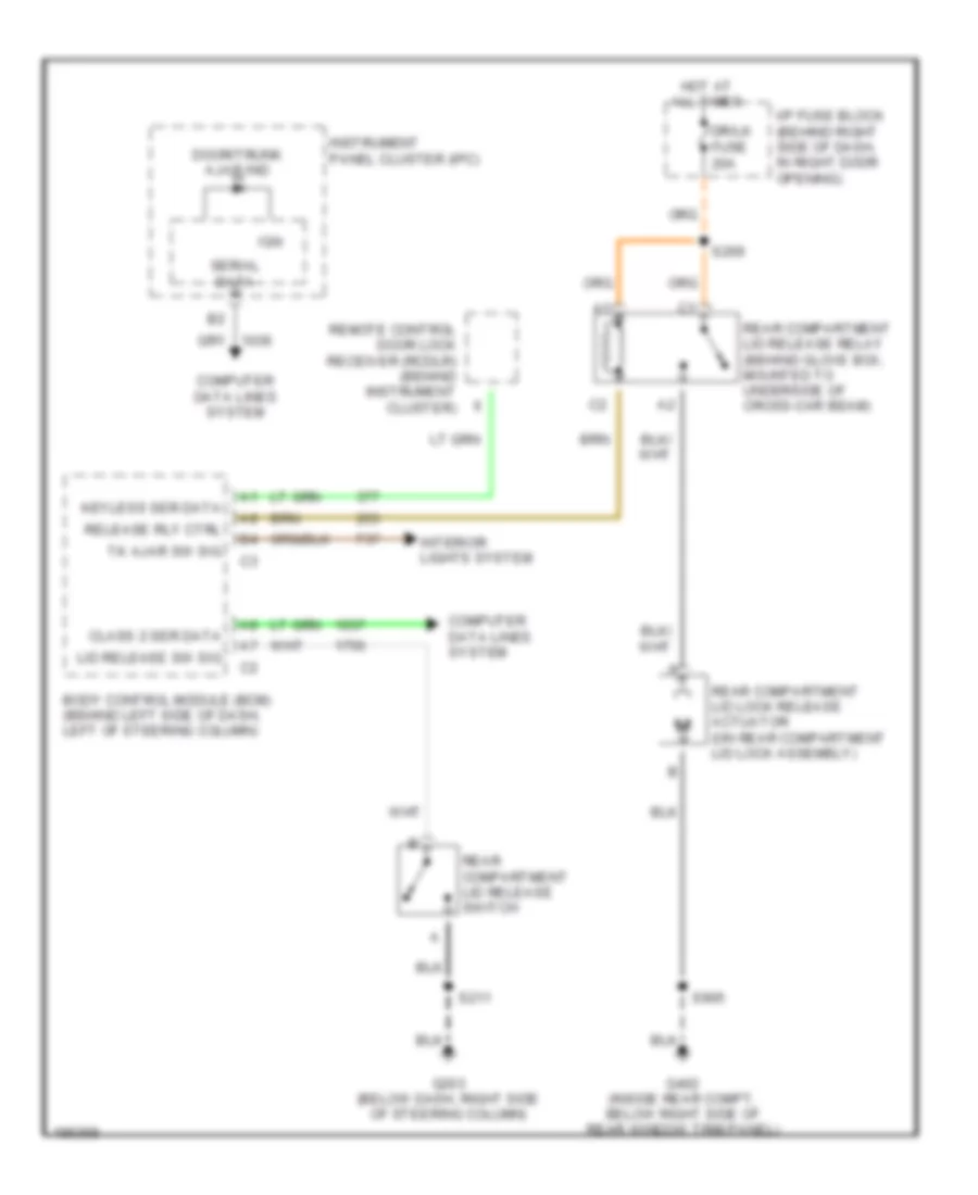
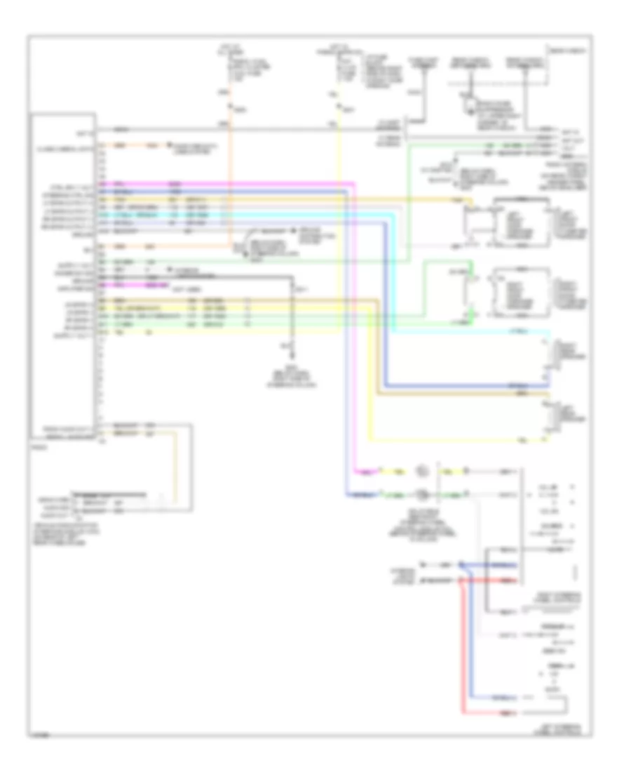
БАГАЖНИК ЗАДНЯЯ ДВЕРЬ ЛЮЧОК ТОПЛИВНОГО БАКА
Электросхема открывания багажника для Buick Regal GS 2004
 https://portal-diagnostov.com/license.html
Automotive Electricians Portal FZCO
Automotive Electricians Portal FZCO
https://portal-diagnostov.com/license.html
https://portal-diagnostov.com/license.html
Automotive Electricians Portal FZCO
Automotive Electricians Portal FZCOЭлектросхема открывания багажника для Buick Regal GS 2004 - Список элементов:
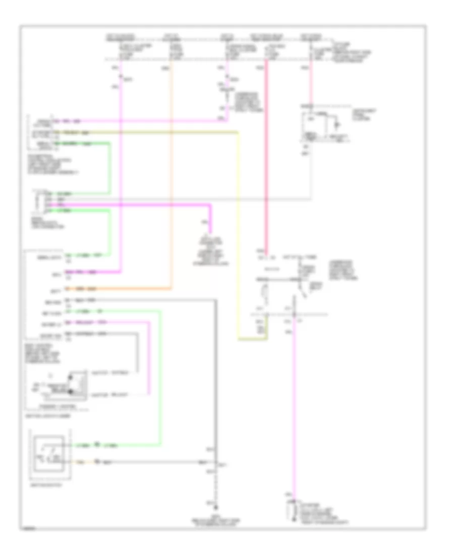
- Body control module (bcm) (behind left side of dash, left of steering column)
- Class 2 ser data
- Computer data lines system
- Door/trunk ajar ind
- Dr/lk fuse 20a
- G203 (below dash, right side of steering column)
- G402 (inside rear compt, below right side of rear window trim panel)
- Hot at all times
- I/p fuse block (behind right side of dash, in right door opening)
- Ign
- Instrument panel cluster (ipc)
- Interior lights system
- Keyless ser data
- Lid release sw sig
- Rear compartment lid lock release actuator (on rear compartment lid lock assembly)
- Rear compartment lid release relay (behind glove box, mounted to underside of cross-car beam)
- Rear compartment lid release switch
- Release rly ctrl
- Remote control door lock receiver (rcdlr) (behind instrument cluster)
- S211
- S269
- S905
- Serial data
- Tk ajar sw sig
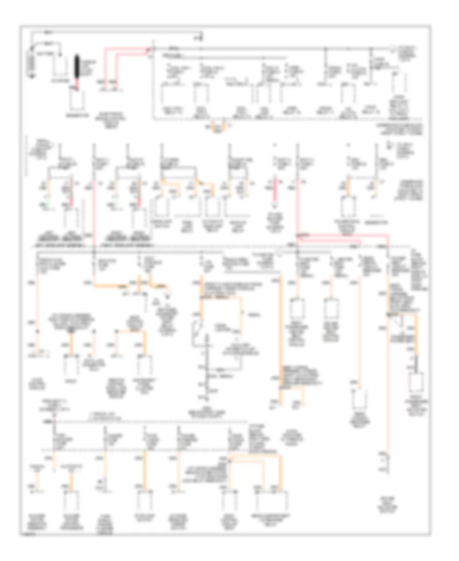
БЛОК ПРЕДОХРАНИТЕЛЕЙ И РЕЛЕ
Электросхема блока предохранителей и реле (1 из 3) для Buick Regal GS 2004
 https://portal-diagnostov.com/license.html
Automotive Electricians Portal FZCO
Automotive Electricians Portal FZCO
https://portal-diagnostov.com/license.html
https://portal-diagnostov.com/license.html
Automotive Electricians Portal FZCO
Automotive Electricians Portal FZCOЭлектросхема блока предохранителей и реле (1 из 3) для Buick Regal GS 2004 - Список элементов:
- (body wiring harness, below right front seat, 60 cm from c312 breakout) s326
- (body wiring harness, in rear compt, 6.5 cm from right rear radio speaker breakout) s440
- (i/p wiring harness, right side of steering column, 19 cm from radio breakout) s202
- (regal)
- 60a
- A/c clutch fuse 23 10a
- A/c clutch relay 15
- Abs fuse 1
- Accy pwr bus fuse 15a
- Audio amplifier (w/ premium radio)
- Automatic a/c
- Automatic headlamp relay
- Auxiliary power outlet (in floor console)
- Back-up lamp relay
- Batt 1 fuse 7 60a
- Batt 2 fuse 4 60a
- Batt 3 fuse 3 60a
- Battery
- Bcm pwr fuse 10a
- Blower motor control processor
- Blower motor resistor assembly
- Body control module (bcm)
- C2 l c12
- Cigar lighter
- Cool fan 1 fuse 6 25a
- Cool fan 1 relay 12
- Cool fan 2 fuse 24 15a
- Cool fan 2 relay 9
- Cool fan 3 relay 10
- Crank fuse 2 40a
- Crank relay 11
- Data link connector (dlc)
- Door locks fuse 20a
- Driver heated seat control module
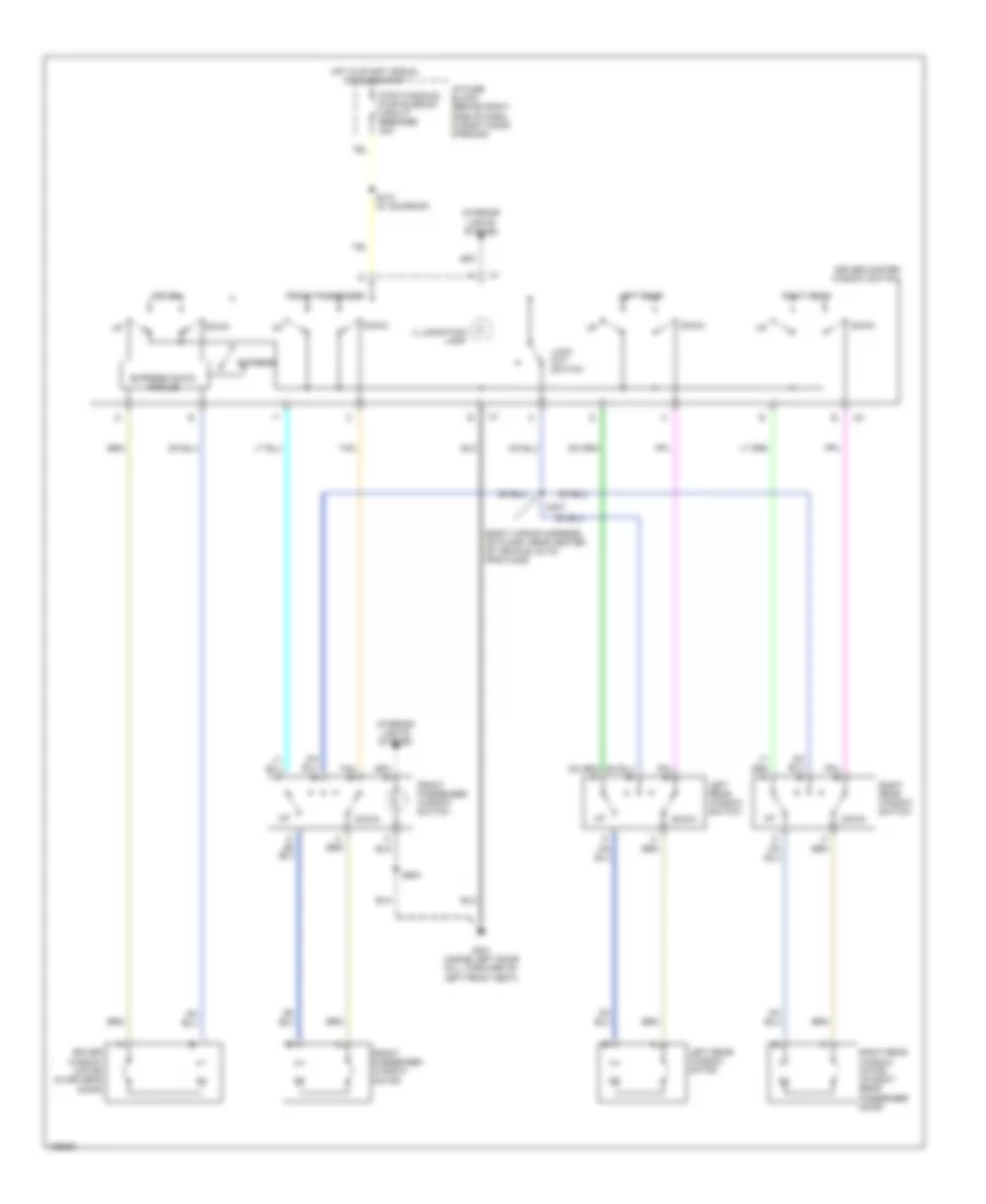
- Driver seat adjuster switch
- E10
- E11
- E12
- Ecm fuse 22 10a
- Electronic brake control module (ebcm)
- F/pmp fuse 35 15a
- F/pmp relay 19
- F/pmp spd cont relay 18 (3.8l (vin 1) w/ front fog lamp)
- Fog lamp relay 17
- Fog lp fuse 31 10a (regal)
- From batt 2 fuse 4 (diagram 1 of 3)
- From f/pmp a fuse 35 (diagram 1 of 3)
- Front passenger heated seat control module
- Front passenger seat adjuster switch
- Fusible link (10 ga- rust)
- G200 (behind right side of dash compt)
- Gen fuse 21 10a
- Generator
- Hazard fuse 15a
- Hdlp l fuse 36 15a
- Hdlp r fuse 32 15a
- Headlamp switch
- High blower fuse 30a
- Horn fuse 27 15a
- Horn relay 16
- Hvac control module
- I/p fuse block (behind right side of dash, in right door opening)
- I/p fuse block (behind right side of dash, in right door opening)
- Instrument panel cluster (ipc)
- L heated seat fuse 15a (regal)
- Left headlamp assembly
- Left high beam headlamp
- Left low beam headlamp
- Lp park fuse 34 20a
- Ltr fuse 20a
- M10
- Manual a/c
- Nca
- Outside rearview mirror switch
- Park lamp relay
- Power mirrors fuse 2a
- Power seat circuit breaker 30a
- Powertrain control module (pcm)
- R heated seat fuse 15a (regal)
- R/cmpt rel fuse 33 7.5a
- R10
- R11
- Radio
- Radio prem sound fuse 15a
- Radio,hvac rfa,cluster aldl fuse 15a
- Rear compartment lid release relay
- Rear defog circuit breaker 30a
- Rear window defogger relay
- Red
- Red a
- Regal
- Remote control door lock receiver (rcdlr)
- Right headlamp assembly
- Right high beam headlamp
- Right low beam headlamp
- S230
- S269 (i/p wiring harness, near blower motor, 13 cm from door lock relay breakout)
- S275
- S335
- Starter
- Stop lamps fuse 15a
- Stoplamp switch
- T10
- To hdlp l fuse 36 (diagram 1 of 3)
- To high blower fuse (diagram 1 of 3)
- To ign 2 fuse 8 (diagram 2 of 3)
- To onstar fuse, diagram (2 of 3)
- To retained accessory power (rap) relay (diagram 2 of 3)
- Turn signal/ hazard flasher module
- Underhood fuse block (mounted to right front strut tower)
- W/ passenger power seat
- W/ rap
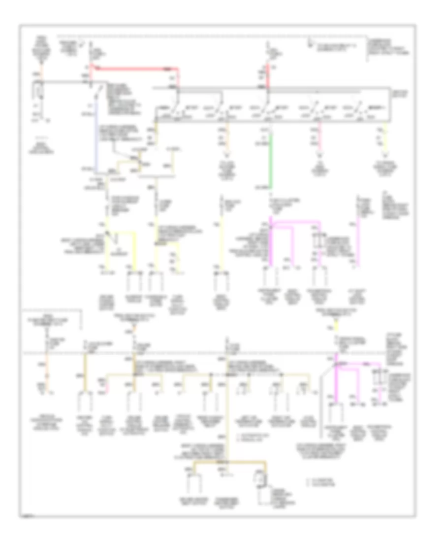
Электросхема блока предохранителей и реле (2 из 3) для Buick Regal GS 2004
 https://portal-diagnostov.com/license.html
Automotive Electricians Portal FZCO
Automotive Electricians Portal FZCO
https://portal-diagnostov.com/license.html
https://portal-diagnostov.com/license.html
Automotive Electricians Portal FZCO
Automotive Electricians Portal FZCOЭлектросхема блока предохранителей и реле (2 из 3) для Buick Regal GS 2004 - Список элементов:
- (body wiring harness, on top of tunnel between front seat, 10 cm from c250 breakout) s323
- (i/p wiring harness, behind center of dash, 4 cm from radio breakout) s233
- (i/p wiring harness, near blower motor, 4 cm from door lock relay breakout)
- (i/p wiring harness, right side of steering column near, c201, 1 cm from sp205 breakout) s240
- (i/p wiring harness, right side of steering column, 13 cm from instrument cluster breakout)
- A/t shift lock control switch
- A10
- Acc
- Automatic a/c
- B10
- Bcm acc fuse 10a
- Body control module (bcm)
- C5 c
- Crank signal, bcm, cluster fuse 10a
- Cruise control module (w/ electronic automatic)
- Cruise control release switch
- Cruise fuse 10a
- Driver heated seat switch
- Driver window master switch
- From gen d fuse 21 (diagram 1 of 3)
- From ignition switch (diagram 2 of 3)
- From inadv power bus fuse (diagram 1 of 3)
- From r heated seat fuse (diagram 1 of 3)
- Heater- a/c control (manual a/c)
- Hvac control module
- Hvac fuse 10a
- I/p fuse block (behind right side of dash, in right door opening)
- Ign 0,cluster, pcm & bcm fuse 10a
- Ign1 fuse 5 30a
- Ign2 fuse 8 60a
- Ignition switch
- Inside rearview mirror (w/ reading lamps)
- Instrument panel cluster (ipc)
- Left air temperature actuator
- Lock
- Low blower fuse 20a
- Manual a/c
- Nca
- Off
- Onstar fuse 5a
- Park/ lock fuse (regal) 10a
- Passenger heated seat switch
- Pnk
- Powertrain control module (pcm)
- Pwr windows pwr sunroof circuit breaker 30a
- Rear window defogger relay
- Red
- Retained accessory power (rap) relay (behind glove box, mounted to underside of cross-car beam)
- Right air temperature actuator
- Run
- S234
- S263
- S270 (i/p wiring harness, behind right side of dash, 4 cm from blower motor control module)
- S410 (body wiring harness, left floor, under rear seat, 7 cm from c405 breakout)
- Start
- Sunroof module
- To crank signal fuse (diagram 2 of 3)
- To ign main relay 13 (diagram 3 of 3)
- To low blower fuse (diagram 2 of 3)
- To s228 (diagram 3 of 3)
- Turn signal/ multi- function switch
- Underhood fuse block (mounted to right front strut tower)
- Vacuum control assembly (automatic a/c)
- Vehicle communications interface module (vcim)
- W/ onstar
- W/ rap
- W/ sunroof
- W/o onstar
- W/o rap
- Windshield wiper motor
- Wiper fuse 25a
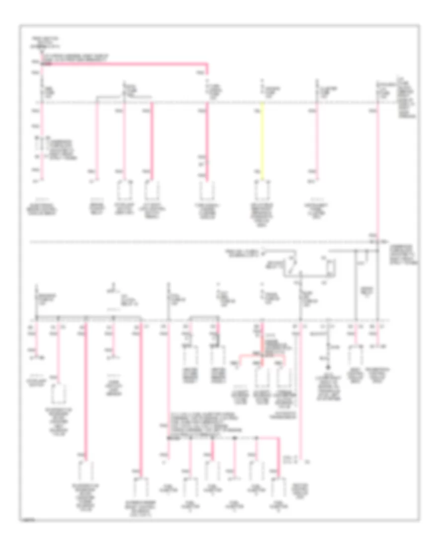
Электросхема блока предохранителей и реле (3 из 3) для Buick Regal GS 2004
 https://portal-diagnostov.com/license.html
Automotive Electricians Portal FZCO
Automotive Electricians Portal FZCO
https://portal-diagnostov.com/license.html
https://portal-diagnostov.com/license.html
Automotive Electricians Portal FZCO
Automotive Electricians Portal FZCOЭлектросхема блока предохранителей и реле (3 из 3) для Buick Regal GS 2004 - Список элементов:
- (3.1l (vin j): fuel injector wiring harness, top of engine, 2 cm from fuel injector 2 breakout) (3.8l (vin k), 3.8l (vin 1): engine wiring harness, top left of engine, 6 cm from c110 breakout) s109
- (3.1l)
- (3.8l)
- (i/p wiring harness, right side of dash, 24 cm from g200 breakout) s228
- (inside transaxle housing,19 cm from c113) s115
- 1-2 shift solenoid (1-2 ss) valve
- 2-3 shift solenoid (2-3 ss) valve
- A/c clutch relay 15
- A/t shift lock control switch (regal)
- A11
- Abs fuse 10a
- Air bag fuse 10a
- Automatic transmission
- B12
- Body control module (bcm)
- Brake- to-shift relay
- Btsi fuse 10a
- C113
- Cluster fuse 10a
- Crank relay
- Electronic brake control module (ebcm)
- Elek ign fuse 25 15a
- Eng emis fuse 30 10a
- Evaporative emissions (evap) canister purge solenoid valve
- Evaporative emissions (evap) canister vent solenoid valve
- F/inj fuse 28 15a
- From ign 1 fuse 5 e (diagram 2 of 3)
- From ignition switch (diagram 2 of 3)
- Front of engine, on transaxle stud, left of starter)
- Fuel injector
- G113 (lower right
- Heated oxygen sensor (ho2s) 1
- Heated oxygen sensor (ho2s) 2
- I/p fuse block (behind right side of dash, in right door opening)
- Ign main relay 13
- Ignition control module (icm)
- Inflatable restraint sensing & diagnostic module (sdm)
- Instrument panel cluster (ipc)
- K10
- Mass air flow (maf) sensor
- Nca
- Oxy sen fuse 29 15a
- Pcm,bcm u/h fuse 10a
- Pnk
- Powertrain control module (pcm)
- Red
- S106
- Stoplamp switch
- Stoplamp switch (century)
- Supercharger boost control solenoid (3.8l (vin 1))
- Torque converter clutch solenoid valve
- Trans fuse 26 10a
- Turn signal fuse 10a
- Turn signal/ hazard flasher module
- Underhood fuse block (mounted to right front strut tower)
БЛОКИ УПРАВЛЕНИЯ КУЗОВОМ
Электросхема блоков управления кузовом для Buick Regal GS 2004
 https://portal-diagnostov.com/license.html
Automotive Electricians Portal FZCO
Automotive Electricians Portal FZCO
https://portal-diagnostov.com/license.html
https://portal-diagnostov.com/license.html
Automotive Electricians Portal FZCO
Automotive Electricians Portal FZCOЭлектросхема блоков управления кузовом для Buick Regal GS 2004 - Список элементов:
- (rap)
- (regal)
- A/t shift lock sol sup volt
- A10
- A11
- A12
- Accy power bus fuse 15a
- Anti-lock brakes system
- Anti-theft system
- B10
- B11
- B12
- Backup lamp rly ctrl
- Bcm acc fuse 10a
- Bcm power fuse 10a
- Body control module (bcm) (behind left side of dash, left of steering column)
- C2 c2
- Computer data lines system
- Courtesy lamp low ctrl
- Courtesy lamp sw out
- Crank, signal, bcm, cluster fuse 10a
- D2 c2
- Door locks fuse 20a
- Door locks system
- Driver door ajar sw sig
- Driver seat belt sw input
- Drl mod output-park brake
- Drl photocell ret
- Drl photocell sig
- Exterior lamps circuit
- Exterior lights system
- Fog lamp sw out
- Fuse output-acc/run/crank
- Fuse output-accessory
- Fuse output-bat
- Fuse output-crank
- Fuse output-ignition 1
- G201 (below dash, left side of steering column)
- G203 (below dash, right side of steering column)
- Grd
- Headlamp sw output
- Headlamp sw sig
- Headlights system
- Horn relay output
- Horns system
- Hot at all times
- Hot in acc or run
- Hot in off, run or start
- Hot in run or start
- Hot in start
- I/p fuse block (behind right side of dash, in right door opening)
- Ign 0, cluster, pcm & bcm fuse 10a
- Ignition key resistor lo ref
- Ignition key resistor sig
- Instrument cluster system
- Interior lights system
- Key ignition sw sig
- Lf turn sig lamp feed
- Lf turn sig sw output
- Low tire press reset sw sig
- Park lamp sw sig-off
- Park lamp sw sig-on
- Pcm, bcm u/h fuse 10a
- Pnk
- Power distribution system
- Pwr dr lk mtr feed
- Pwr dr lock sw out
- Pwr dr lock sw output
- Rap relay ctrl
- Rf turn sig lamp feed
- Rf turn sig sw output
- Right ft door open sw sig
- S211
- S234
- S269
- S270
- S283
- Serial data sig
- Serial data signal class 2
- Shift interlock system
- Tan
- Traction ctrl sig sw
- Trunk ajar sw sig
- Trunk lid release sw sig
- Trunk release rly feed
- Trunk, tailgate, fuel doors system
- Underhood fuse block (mounted to right front strut tower)
- Warning system
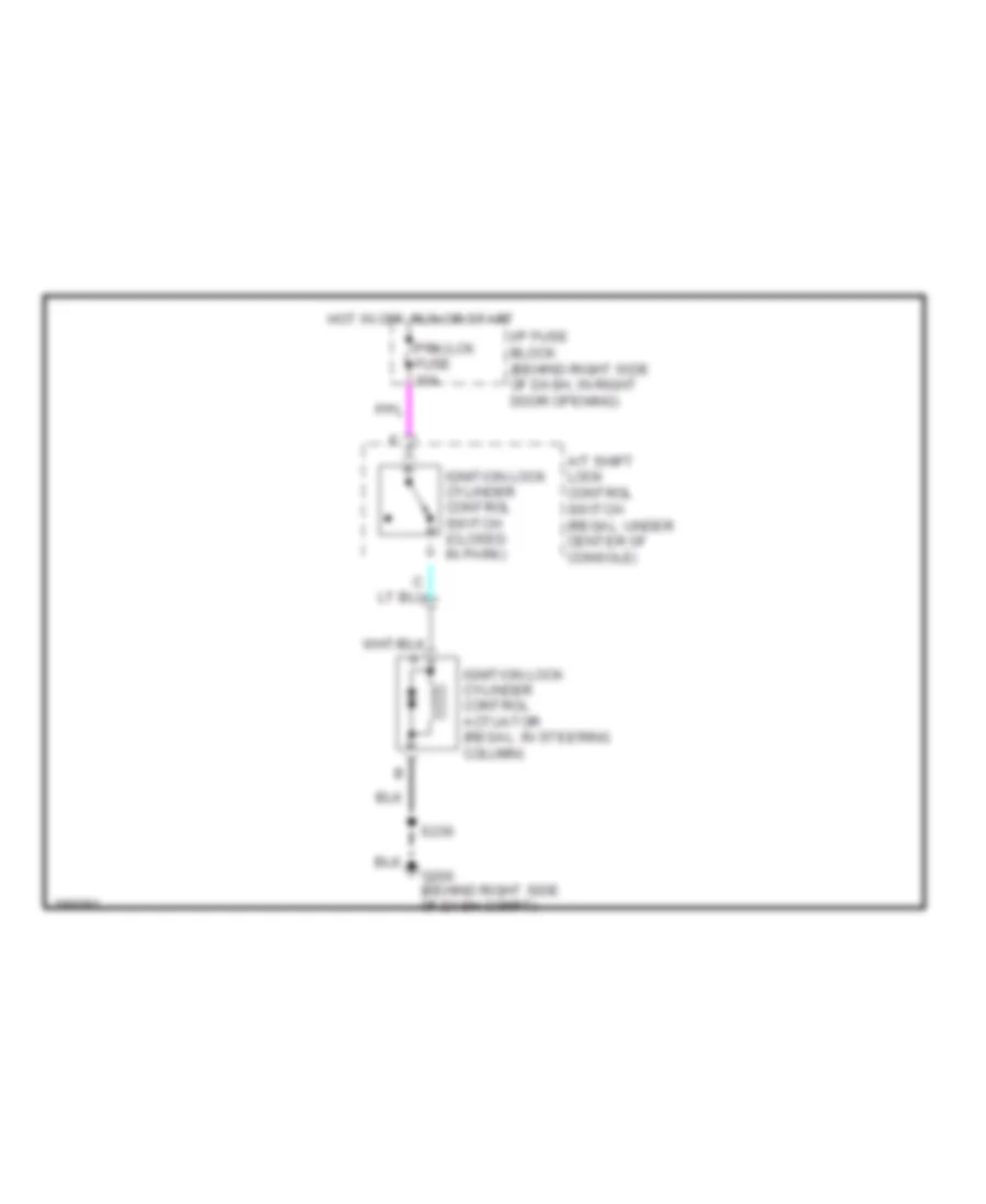
БЛОКИРОВКИ СЕЛЕКТОРА СТОЯНОЧНЫЙ ТОРМОЗ
Электросхема соленоида блокировки замка зажигания для Buick Regal GS 2004
 https://portal-diagnostov.com/license.html
Automotive Electricians Portal FZCO
Automotive Electricians Portal FZCO
https://portal-diagnostov.com/license.html
https://portal-diagnostov.com/license.html
Automotive Electricians Portal FZCO
Automotive Electricians Portal FZCOЭлектросхема соленоида блокировки замка зажигания для Buick Regal GS 2004 - Список элементов:
- A/t shift lock control switch (regal: under center of console)
- G200 (behind right side of dash compt)
- Hot in off, run or start
- I/p fuse block (behind right side of dash, in right door opening)
- Ignition lock cylinder control actuator (regal: in steering column)
- Ignition lock cylinder control switch (closed in park)
- Prk/lck fuse 10a
- S230
Электросхема блокировки селектора для Buick Regal GS 2004
 https://portal-diagnostov.com/license.html
Automotive Electricians Portal FZCO
Automotive Electricians Portal FZCO
https://portal-diagnostov.com/license.html
https://portal-diagnostov.com/license.html
Automotive Electricians Portal FZCO
Automotive Electricians Portal FZCOЭлектросхема блокировки селектора для Buick Regal GS 2004 - Список элементов:
- (locks shift lever when energized)
- A/t shift lock control solenoid
- A/t shift lock control switch (regal: under center of console)
- A/t shift lock sol pwr
- Automatic transmission
- Body control module (bcm) (behind left side of dash, left of steering column)
- Brake to shift relay (left of i/p fuse block)
- Btsi fuse 10a
- Computer data lines system
- Data line
- G113 (lower right front of engine, on transaxle stud, left of starter)
- G203 (below dash, right side of steering column)
- Hot in run, bulb test or start
- I/p fuse block (behind right side of dash, in right door opening) pnk
- Park lock solenoid (unlocks shift lever when energized)
- Pnk
- Powertrain control module (pcm) (left front side of engine compt, in air cleaner assembly)
- S106
- S211
- Sig a
- Sig b
- Sig c
- Sig p
- Stop lamp switch (open when brake pedal depressed) (on brake pedal support bracket)
- Tan/
- Transmission internal mode switch (ims)
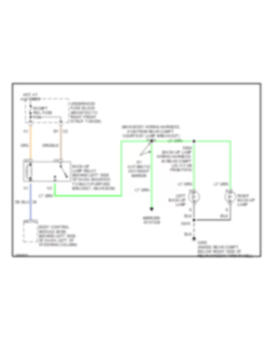
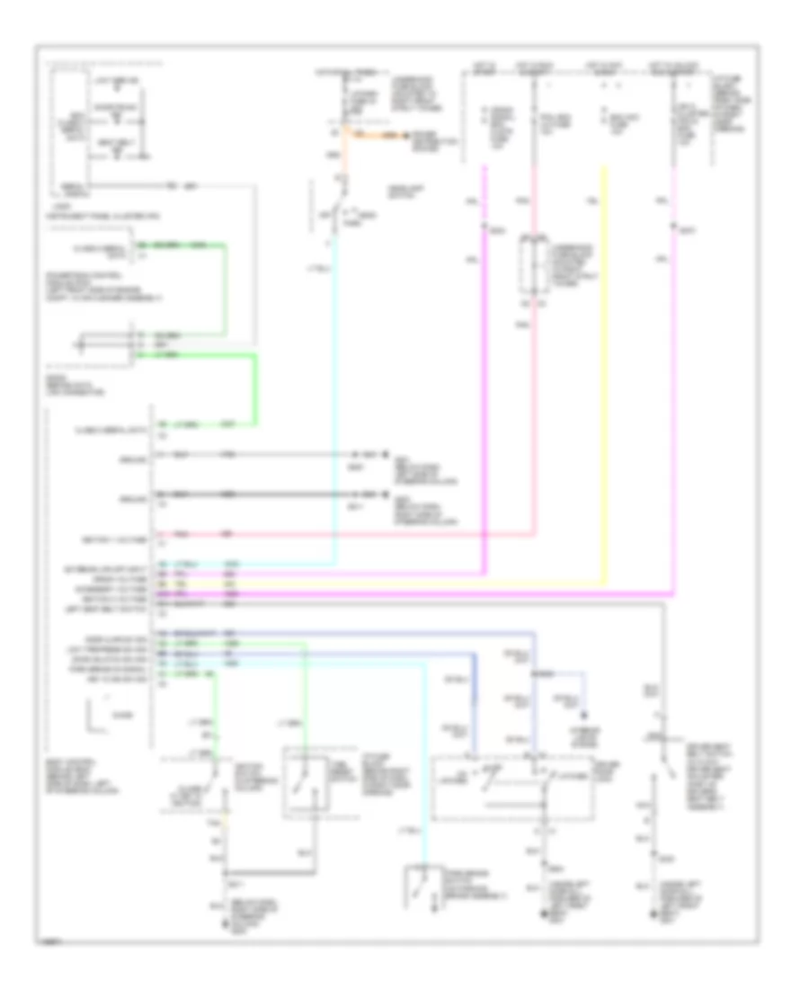
ВНЕШНЕЕ ОСВЕЩЕНИЕ
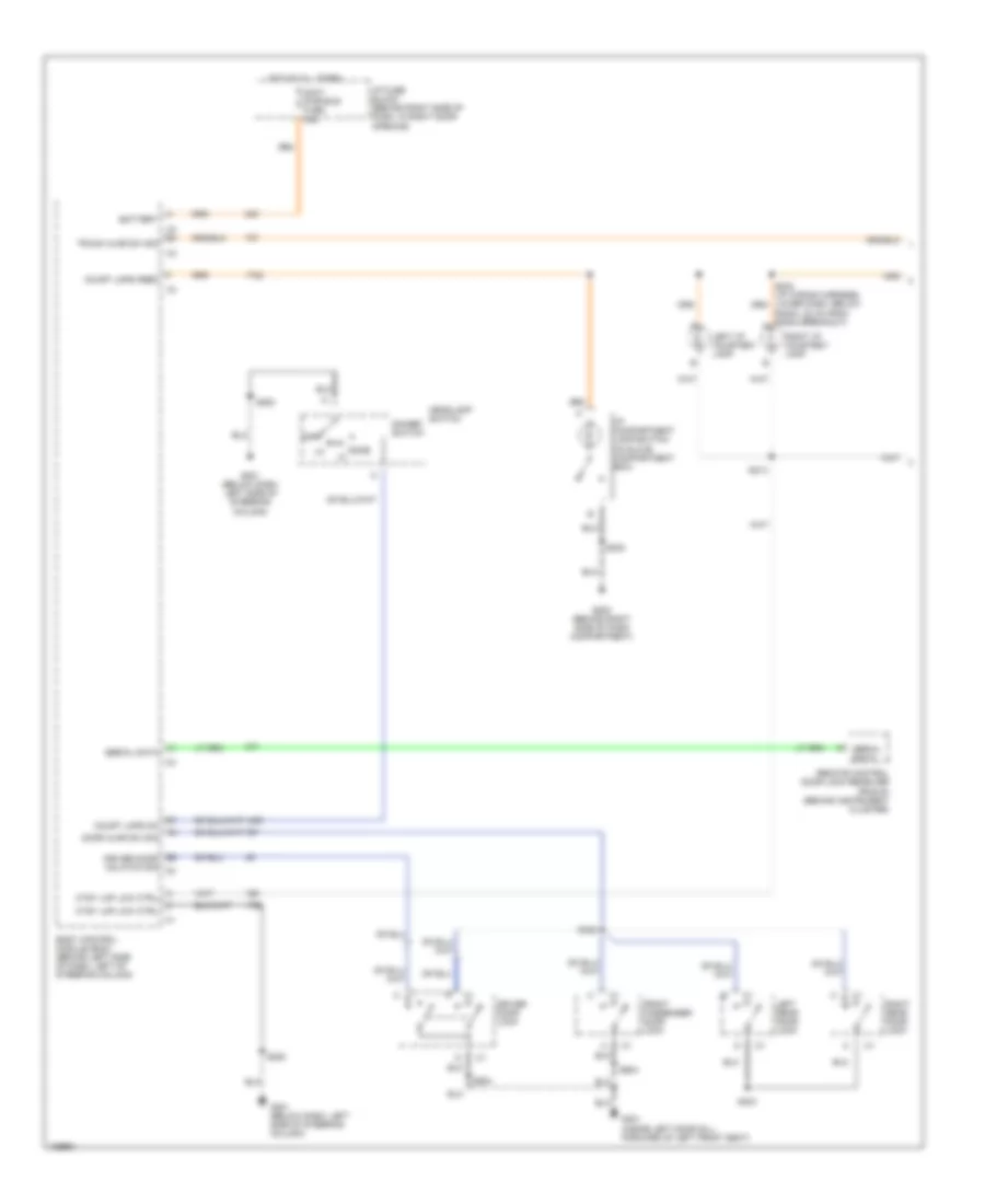
Электросхема заднего хода для Buick Regal GS 2004
 https://portal-diagnostov.com/license.html
Automotive Electricians Portal FZCO
Automotive Electricians Portal FZCO
https://portal-diagnostov.com/license.html
https://portal-diagnostov.com/license.html
Automotive Electricians Portal FZCO
Automotive Electricians Portal FZCOЭлектросхема заднего хода для Buick Regal GS 2004 - Список элементов:
- (main body wiring harness, 9 cm from rear compt, courtesy lamp breakout) s424
- A8 c3
- B1 c2
- Back-up lamp relay (behind left side of dash, mounted to multi-purpose bracket, near bcm)
- Body control module (bcm) (behind left side of dash, left of steering column)
- G402 (inside rear compt, below right side of rear window trim panel)
- Hot at all times
- Left back-up lamp
- Mirrors system
- R/cmpt rel fuse 7.5a
- Right back-up lamp
- S904 (back-up lamp wiring harness, in rear compt lid, 6.5 cm from p915)
- S915
- Underhood fuse block (mounted to right front strut tower)
- W/ automatic day/night mirror
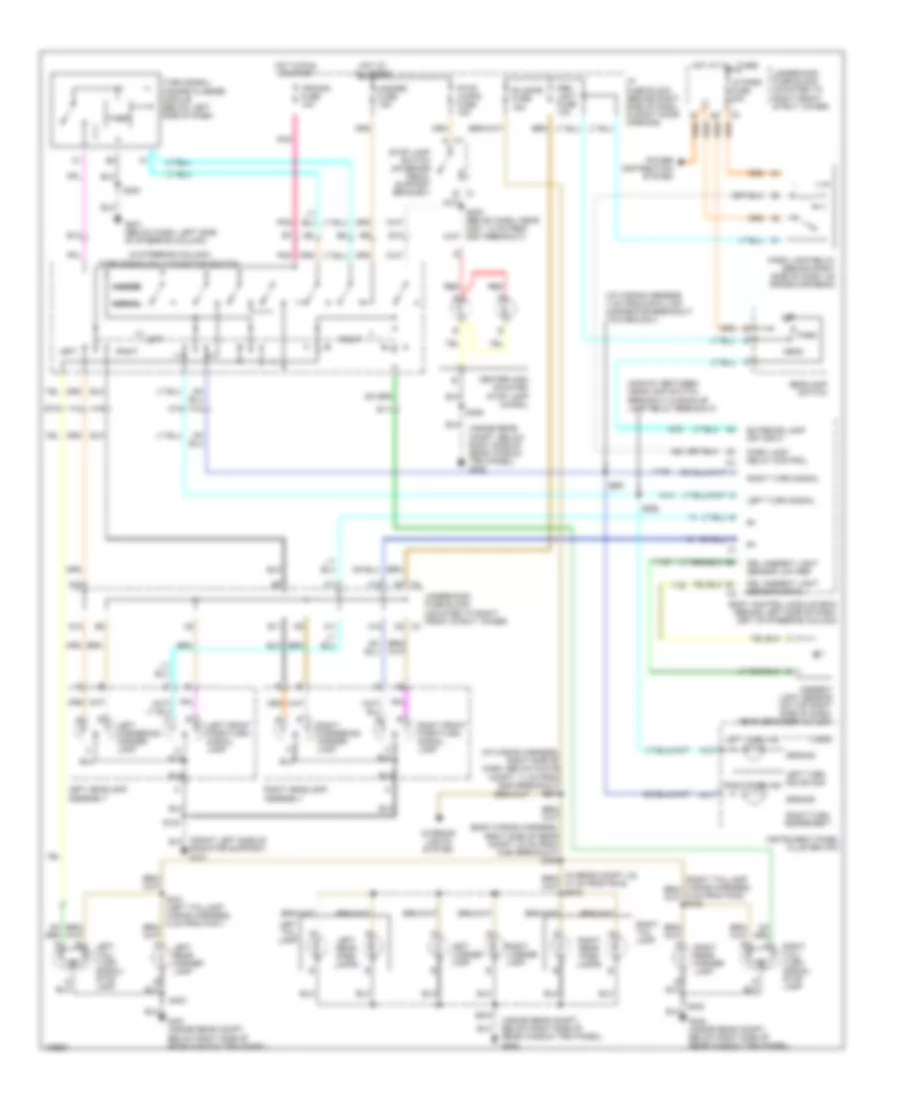
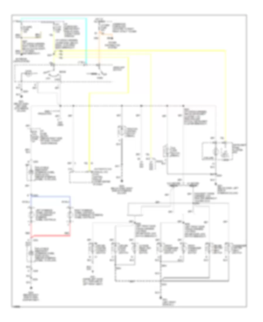
Электросхема внешнего освещения для Buick Regal GS 2004
 https://portal-diagnostov.com/license.html
Automotive Electricians Portal FZCO
Automotive Electricians Portal FZCO
https://portal-diagnostov.com/license.html
https://portal-diagnostov.com/license.html
Automotive Electricians Portal FZCO
Automotive Electricians Portal FZCOЭлектросхема внешнего освещения для Buick Regal GS 2004 - Список элементов:
- (body wiring harness, right side of rear compt, 33 cm from c390 breakout) s408
- (i/p wiring harness, 7 cm from data link connector breakout, toward c201)
- (i/p wiring harness, right side of dash, below glove compt, 11 cm from g200 breakout) s267
- (in steering column) turn signal/multi-function switch
- (inside rear compt, below right side of rear window trim panel) g402
- (midway between headlamp switch breakout & back-up lamp relay breakout)
- A10
- A11
- A12
- A13
- A14
- A15
- Ambient light sensor (on top right side of dash, near defogger outlet)
- B c1
- Body control module (bcm) (behind left side of dash, left of steering column)
- C1 a
- C2 f8
- C3 c5
- Center high mounted stop lamp (chmsl)
- D12
- Drl ambient light sensor low ref
- Drl ambient light sensor signal
- E10
- E11
- E12
- E13
- Exterior lamp off input
- F11
- F12
- G201 (below dash, left side of steering column)
- G401 (inside rear compt, below right side of rear window trim panel)
- G402 (inside rear compt, below right side of rear window trim panel)
- Ground
- Hazard
- Hazard fuse 15a
- Head
- Headlamp switch
- Hot at all times
- Hot in run or start
- I/p fuse block (behind right side of dash, in right door opening)
- Instrument panel cluster (ipc)
- Interior lights system
- Left
- Left cornering/ marker lamp
- Left front park/turn signal lamp
- Left headlamp assembly
- Left license lamp
- Left rear marker lamp
- Left rear park lamps
- Left tail lamp
- Left tail/ turn signal/ stop lamp
- Left turn ind
- Left turn sig sw sig
- Left turn signal
- Logic
- Lp park fuse 20a
- Normal
- Off
- Park
- Park lamp relay (behind right side of dash, on cross-car beam)
- Park lamp relay control
- Pnk
- Power distribution system
- Prk/ lght fuse 10a
- R/lamps fuse 15a
- Radiator support) g101
- Red
- Right
- Right cornering/ marker lamp
- Right front park/turn signal lamp
- Right headlamp assembly
- Right license lamp
- Right rear marker lamp
- Right rear park lamps
- Right tail lamp
- Right tail/ turn signal/ stop lamp
- Right turn ind
- Right turn sig sw sig
- Right turn signal
- S124
- S205 (below dash, near c201, 14 cm from g201 breakout)
- S283
- S291
- S292
- S402
- S403
- S406
- S915
- Stop lamp switch (on brake pedal support bracket)
- Stop lamps fuse 15a
- Timer
- Trn/sig fuse 10a
- Turn signal/ hazard flasher module (below left side of dash)
- Underhood fuse block (mounted to right front strut tower)
ВНУТРЕННЕЕ ОСВЕЩЕНИЕ
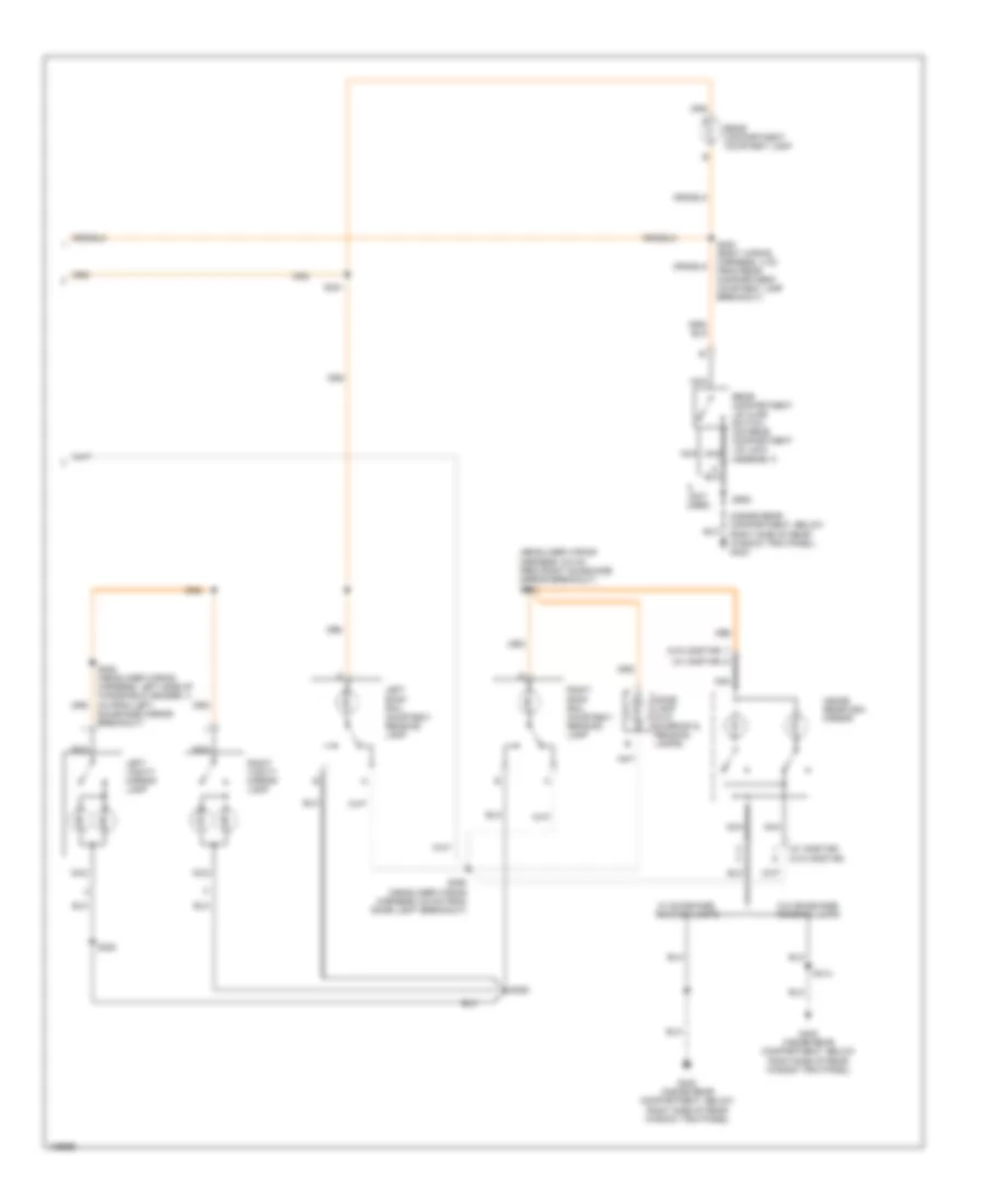
Электросхема подсветки (1 из 2) для Buick Regal GS 2004
 https://portal-diagnostov.com/license.html
Automotive Electricians Portal FZCO
Automotive Electricians Portal FZCO
https://portal-diagnostov.com/license.html
https://portal-diagnostov.com/license.html
Automotive Electricians Portal FZCO
Automotive Electricians Portal FZCOЭлектросхема подсветки (1 из 2) для Buick Regal GS 2004 - Список элементов:
- Accy pwr bus fuse 15a
- B5 driver door unlatch sig c2
- Battery
- Body control module (bcm) (behind left side of dash, left of steering column)
- C4 b4
- Court lmps feed
- Court lmps on
- Ctsy lmp low ctrl
- Dimmer switch
- Dome
- Door ajar sw sig
- Driver door lock
- Front passenger door lock
- G200 (behind right side of dash compartment)
- G201 (below dash, left side of steering column)
- G301 (inside left door sill, forward of left front seat)
- Headlamp switch
- Hot at all times
- I/p compartment lamp/switch (in glove compartment box)
- I/p fuse block (behind right side of dash, in right door opening)
- Left i/p courtesy lamp
- Left rear door lock
- Off
- Radio, 22 cm from radio breakout) a
- Remote control door lock receiver (rcdlr) (behind instrument cluster)
- Right i/p courtesy lamp
- Right rear door lock
- S214
- S230
- S283
- S303
- S322
- S504
- S604
- Serial data
- Trunk ajar sw sig
Электросхема подсветки (2 из 2) для Buick Regal GS 2004
 https://portal-diagnostov.com/license.html
Automotive Electricians Portal FZCO
Automotive Electricians Portal FZCO
https://portal-diagnostov.com/license.html
https://portal-diagnostov.com/license.html
Automotive Electricians Portal FZCO
Automotive Electricians Portal FZCOЭлектросхема подсветки (2 из 2) для Buick Regal GS 2004 - Список элементов:
- (headliner wiring harness, 6.5 cm from right sunshade mirror breakout) s386
- (inside rear compartment, below right side of rear window trim panel) g402
- (not used)
- (w/ onstar)
- (w/o onstar)
- Dome lamp (w/o sunroof & reading lamps)
- G402 (inside rear compartment, below right side of rear window trim panel)
- Inside rearview mirror
- Left roof rail courtesy/ reading lamp
- Left vanity mirror lamp
- Nca
- Rear compartment courtesy lamp
- Rear compartment lid ajar switch (on rear compartment lid lock assembly)
- Right roof rail courtesy/ reading lamp
- Right vanity mirror lamp
- S321
- S382 (headliner wiring harness, left side of windshield header, 4 cm from left sunshade mirror breakout)
- S383
- S385
- S392 (headliner wiring harness, 6.5 cm from dome light breakout)
- S400 (body wiring harness, 4 cm from rear compartment courtesy lamp breakout)
- S414
- S905
- W/ sunshade, reading lamps
- W/o sunshade, reading lamps
Электросхема подсветки приборов для Buick Regal GS 2004
 https://portal-diagnostov.com/license.html
Automotive Electricians Portal FZCO
Automotive Electricians Portal FZCO
https://portal-diagnostov.com/license.html
https://portal-diagnostov.com/license.html
Automotive Electricians Portal FZCO
Automotive Electricians Portal FZCOЭлектросхема подсветки приборов для Buick Regal GS 2004 - Список элементов:
- (5 bulbs)
- (automatic a/c)
- (i/p wiring harness, lower dash, below radio, 15 cm from radio breakout)
- (manual a/c)
- (not used)
- B12
- C16
- C203
- C205
- Dome
- Driver door lock switch
- Driver heated seat switch
- Driver master window switch
- Early production
- Exterior lights system
- Fog lamp switch (regal)
- Front passenger door lock switch
- Front passenger window switch
- G200 (behind right side of dash compartment)
- G200 breakout)
- G201 (below dash, left side of steering column)
- G203 (below dash, right side of steering column)
- G301 (inside left door sill, forward of left front seat)
- G301 (left front door sill)
- Harness, 4 cm from sdm breakout, toward c312) s302
- Head
- Headlamp switch
- High
- Hot at all times
- Hvac control module (lower center of dash)
- I/p fuse block (behind right side of dash, in right door opening)
- Illum
- Inflatable restraint steering wheel module coil (behind steering wheel, in column)
- Instrument panel cluster (ipc)
- Int/ illum fuse 7.5a
- Left steering wheel controls (w/ accessory steering wheel controls)
- Logic
- Low
- Lp park fuse 20a
- Off
- Outside rear view mirror switch
- Park
- Passenger heated seat switch
- Power distribution system
- R/lamps fuse 15a
- Radio
- Red
- Right steering wheel controls (w/ accessory steering wheel controls)
- S211
- S230
- S241
- S283
- S303
- S504
- S506 (left front door wiring harness, 4 cm from driver door lock switch breakout)
- S604
- S606 (left front door wiring harness, 4 cm from driver door lock switch breakout)
- Str/ whl cntrl fuse 2a
- Traction control switch (regal)
- Underhood fuse block (mounted to right front strut tower)
- Vf dim dis sig
- Vf dim sig
- Vf sply volt-1
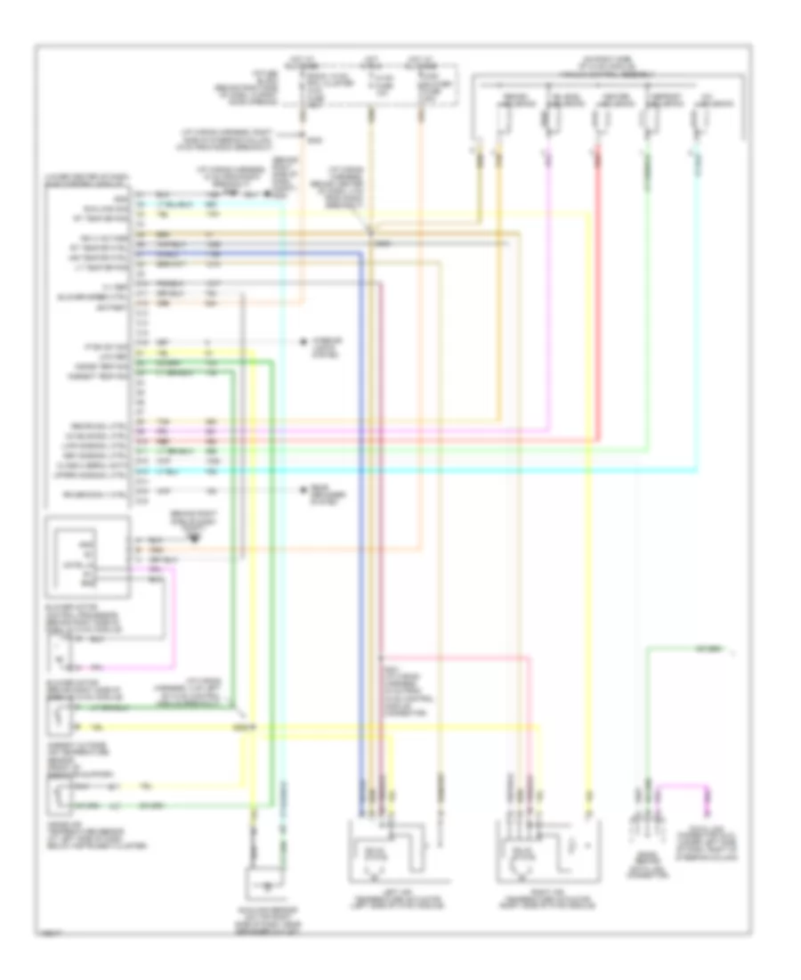
- W/ heated seats
- W/o heated seats
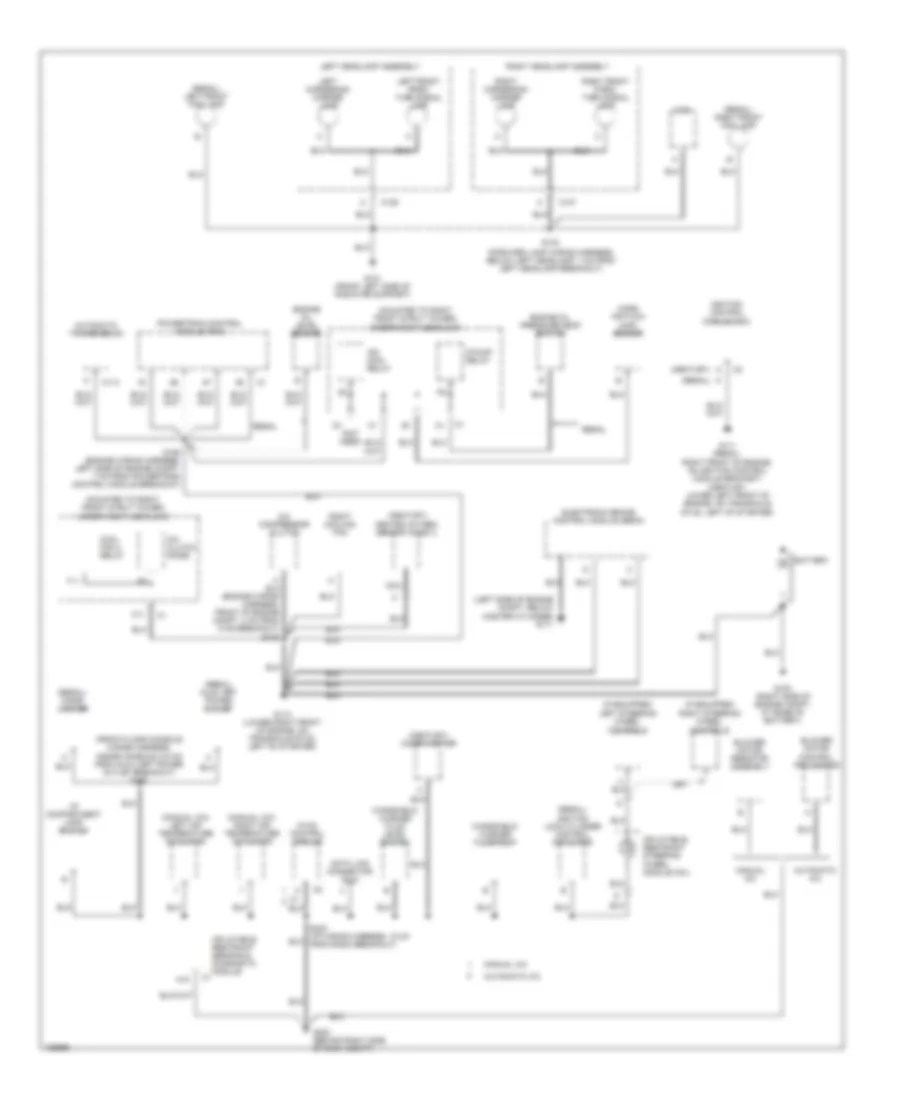
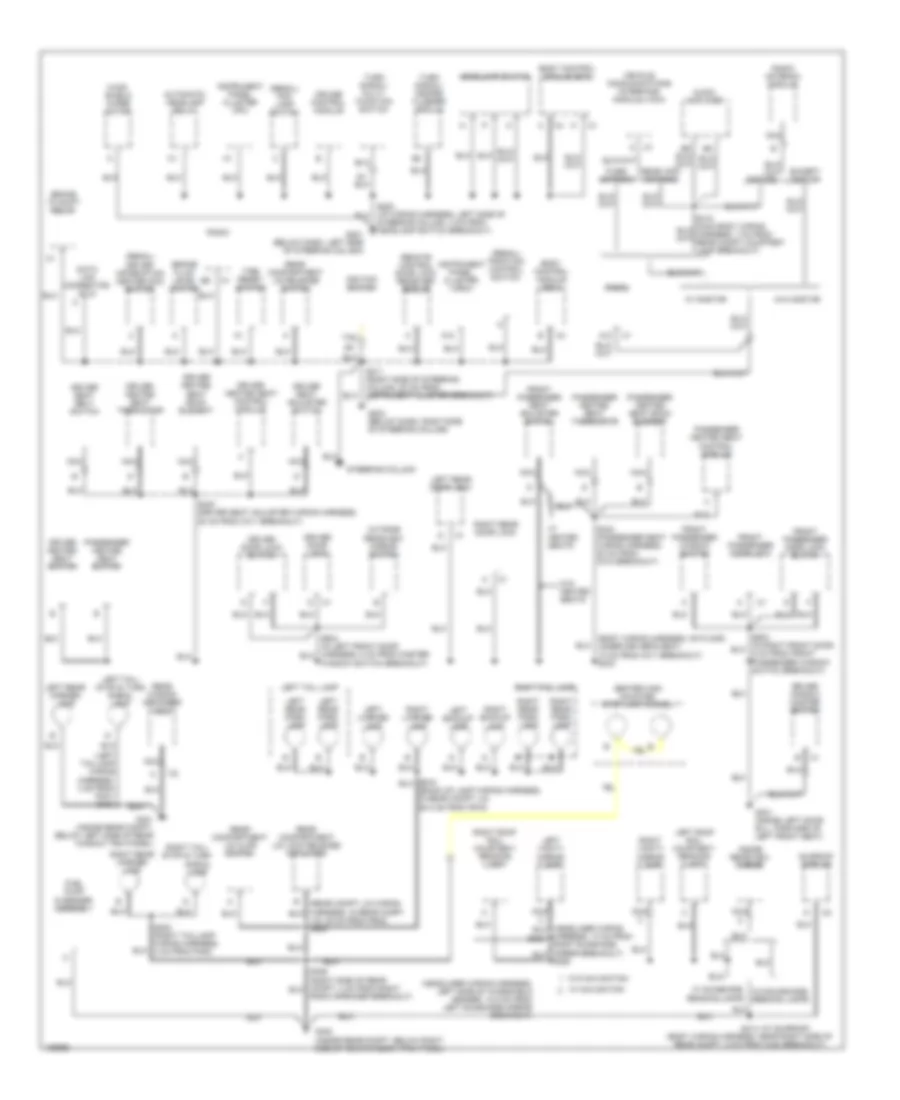
ЗАЗЕМЛЕНИЕ ПОДКЛЮЧЕНИЕ МАССЫ
Электросхема подключение массы заземления (1 из 2) для Buick Regal GS 2004
 https://portal-diagnostov.com/license.html
Automotive Electricians Portal FZCO
Automotive Electricians Portal FZCO
https://portal-diagnostov.com/license.html
https://portal-diagnostov.com/license.html
Automotive Electricians Portal FZCO
Automotive Electricians Portal FZCOЭлектросхема подключение массы заземления (1 из 2) для Buick Regal GS 2004 - Список элементов:
- (century)
- (century) cigar lighter
- (century) heated oxygen sensor (ho2s) 2
- (forward lamp wiring harness, below left headlamp, 7 cm from left headlamp breakout)
- (front floor console wiring harness, inside console, 6.5 cm from auxiliary power outlet breakout) s335
- (if equipped) left steering wheel controls
- (if equipped) right steering wheel controls
- (left side of engine compt, below master cylinder) g171
- (manual a/c) left air temperature actuator
- (manual a/c) right air temperature actuator
- (mounted to right front strut tower) underhood fuse block
- (not used)
- (regal)
- (regal) auxiliary power outlet
- (regal) cigar lighter
- (regal) ignition lock cylinder control actuator
- (regal) left front fog lamp
- (regal) right front fog lamp
- A/c clutch diode
- A/c compressor clutch
- A18
- Automatic a/c
- Automatic transmission
- Battery
- Blower motor control processor
- Blower motor resistor assembly
- C106
- C107
- C11
- C113
- Cool fan 2 relay
- Data link connector (dlc)
- Electronic brake control module (ebcm)
- Engine oil level sensor
- Engine oil pressure (eop) switch
- F/pump relay
- G100 (right side of engine compt, at base of battery)
- G101 (front left side of radiator support)
- G111 (regal: right front of engine, on ignition control module bracket) (century: lower left front of engine, on transaxle stud, left of starter)
- G113 (lower right front of engine, on transaxle stud, left of starter)
- G200 (behind right side of dash compt)
- Horn
- Hvac control module
- I/p compartment lamp/ switch
- Ign main relay
- Ignition control module (icm)
- Inflatable restraint sensing & diagnostic module
- Inflatable restraint steering wheel module coil
- Left cornering/ marker lamp
- Left front park/ turn signal lamp
- Left headlamp assembly
- Manual a/c
- Mass air flow (maf) sensor
- Nca
- Powertrain control module (pcm)
- Regal
- Right cooling fan
- Right cornering/ marker lamp
- Right front park/ turn signal lamp
- Right headlamp assembly
- S106 (engine wiring harness, left side of engine compt, 7 cm from powertrain control module breakout)
- S124
- T11
- Windshield washer fluid level switch
- Windshield washer fluid pump
Электросхема подключение массы заземления (2 из 2) для Buick Regal GS 2004
 https://portal-diagnostov.com/license.html
Automotive Electricians Portal FZCO
Automotive Electricians Portal FZCO
https://portal-diagnostov.com/license.html
https://portal-diagnostov.com/license.html
Automotive Electricians Portal FZCO
Automotive Electricians Portal FZCOЭлектросхема подключение массы заземления (2 из 2) для Buick Regal GS 2004 - Список элементов:
- (back-up lamp wiring harness, in rear compt lid, 29.5 cm from p915)
- (body wiring harness, on floor, under driver's seat, 10 cm from c311 breakout) s303
- (headliner wiring harness, left side of windshield header, 10.5 cm from left sunshade mirror breakout)
- (left taillamp wiring
- (regal) driver information center (dic) switch
- (regal) fog lamp switch
- (regal) traction control switch
- (w/ sunroof)
- A12
- Audio amplifier
- Automatic headlamp relay
- Body control module (bcm)
- Brake fluid level switch
- Brake to shift relay
- Center high mounted stop lamp (chmsl)
- Cruise control module
- Data link connector (dlc)
- Driver door lock
- Driver door lock switch
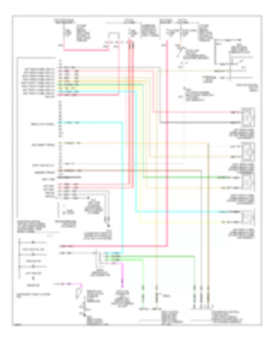
- Driver heated seat back element
- Driver heated seat control module
- Driver heated seat switch
- Driver heated seat thermistor
- Driver seat adjuster switch
- Driver seat belt switch
- Driver window master switch
- Except onstar
- Fixed antenna
- Front passenger door lock
- Front passenger door lock switch
- Front passenger seat adjuster switch
- Front passenger window switch
- Fuel pump & sender assembly
- G201 (below dash, left side of steering column)
- G203 (below dash, right side of steering column)
- G301 (inside left door sill, forward of left front seat)
- G401 (inside rear compt, below left side of rear window trim panel)
- G402 (inside rear compt, below right side of rear window trim panel)
- Harness, 13 cm from s383
- Harness, 3 cm from p401) s403
- Headlamp switch
- Ignition switch
- Inside rearview mirror
- Instrument panel cluster (ipc)
- Left backup lamp
- Left license lamp
- Left rear door lock
- Left rear marker lamp
- Left rear park lamp
- Left roof rail courtesy/ reading lamp
- Left tail lamp
- Left tail/ stop & turn signal lamp
- Left vanity mirror lamp
- Lid, 38 cm from p932) s905
- Nca
- Onstar
- Outside rearview mirror switch
- Passenger heated seat back element
- Passenger heated seat control module
- Passenger heated seat switch
- Passenger heated seat thermistor
- Radio
- Radio antenna module
- Radio speaker breakout)
- Reading lamps
- Rear compartment lid ajar switch
- Rear compartment lid lock release actuator
- Rear compartment lid release switch
- Rear wdo antenna
- Rear window defogger grid
- Remote control door lock receiver (rcdlr)
- Right backup lamp
- Right license lamp
- Right rear door lock
- Right rear marker lamp
- Right rear park lamp
- Right roof rail courtesy/ reading lamp
- Right tail lamp
- Right tail/ stop & turn
- Right vanity mirror lamp
- S211 (right side of steering column, 20 cm from instrument cluster breakout)
- S330 (driver seat adjuster wiring harness, 20 cm from c311 breakout)
- S333 (passenger seat wiring harness, 20 cm from c312 breakout)
- S402 (right taillamp wiring harness, 3 cm from p402)
- S414 (body wiring harness, near right side of rear compt, 5 cm from c420 breakout)
- Signal lamp
- Steering column
- Steering column, 4 cm from headlamp switch breakout)
- Sunroof module
- Tan
- Tire reset switch
- Turn signal/ hazard flasher module
- Turn signal/ multi- function switch
- Vehicle communications interface module (vcim)
- W/ heated seats
- W/ navigation
- W/ onstar
- W/ sunshade, w/o sunshade, reading lamps
- W/o heated seats
- W/o navigation
- W/o onstar
- Wind- shield wiper motor
- Window switch breakout)
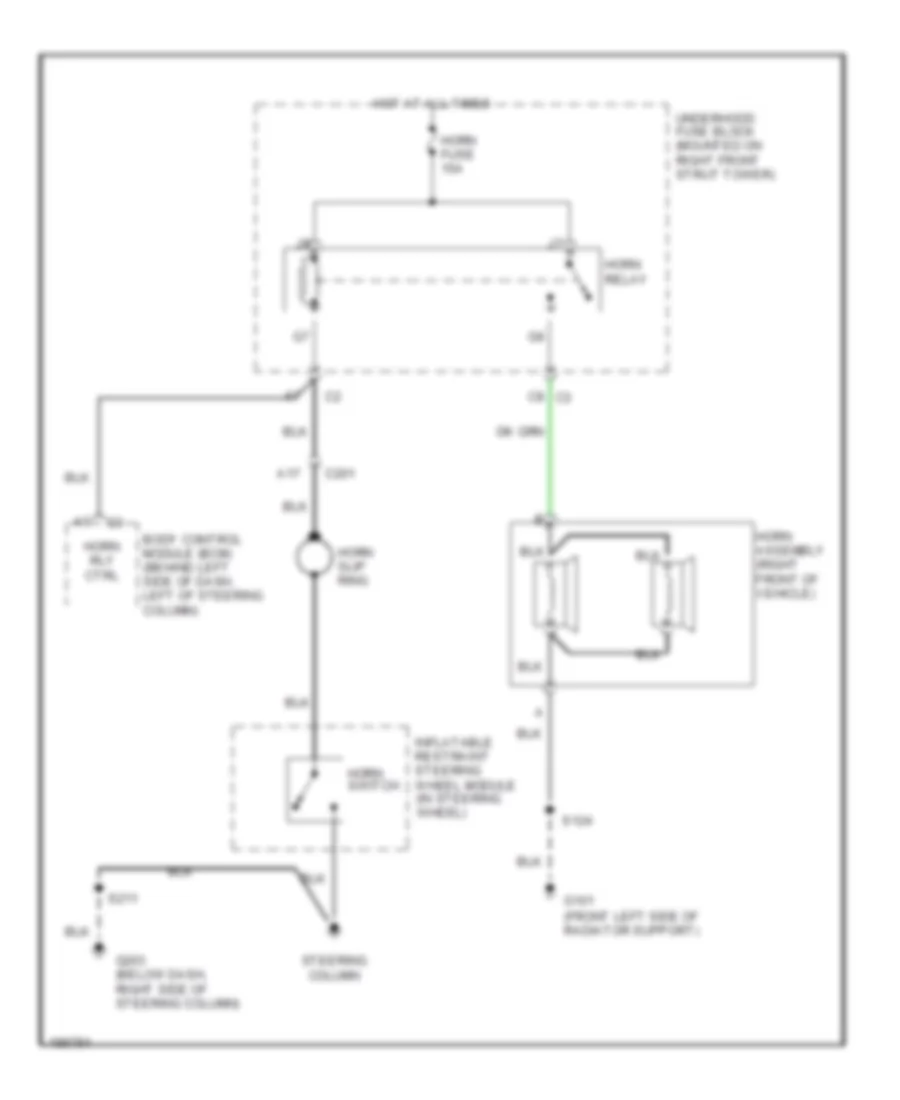
Звуковой сигнал Гудок
Электросхема звукового сигнал Гудка для Buick Regal GS 2004
 https://portal-diagnostov.com/license.html
Automotive Electricians Portal FZCO
Automotive Electricians Portal FZCO
https://portal-diagnostov.com/license.html
https://portal-diagnostov.com/license.html
Automotive Electricians Portal FZCO
Automotive Electricians Portal FZCOЭлектросхема звукового сигнал Гудка для Buick Regal GS 2004 - Список элементов:
- A17
- Body control module (bcm) (behind left side of dash, left of steering column)
- C201
- C8 c3
- G101 (front left side of radiator support)
- G203 (below dash, right side of steering column)
- Horn assembly (right front of vehicle)
- Horn fuse 15a
- Horn relay
- Horn rly ctrl
- Horn slip ring
- Horn switch
- Hot at all times
- Inflatable restraint steering wheel module (in steering wheel)
- S124
- S211
- Steering column
- Underhood fuse block (mounted on right front strut tower)
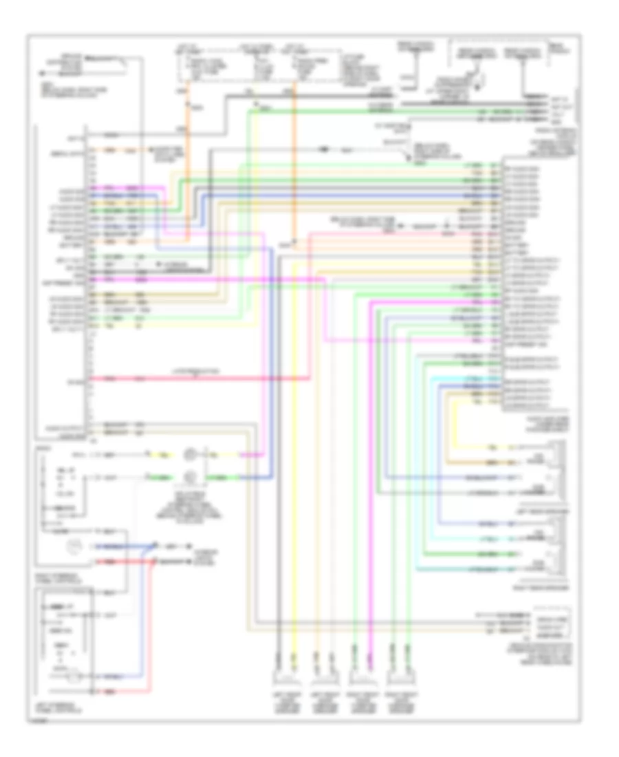
Магнитола Мультимедия
Электросхема магнитолы, С усилитель для Buick Regal GS 2004
 https://portal-diagnostov.com/license.html
Automotive Electricians Portal FZCO
Automotive Electricians Portal FZCO
https://portal-diagnostov.com/license.html
https://portal-diagnostov.com/license.html
Automotive Electricians Portal FZCO
Automotive Electricians Portal FZCOЭлектросхема магнитолы, С усилитель для Buick Regal GS 2004 - Список элементов:
- (below dash, right side of steering column) g203
- (w/ onstar) s418
- A10
- A11
- A12
- Am/fm
- Amp preset sig
- Ant in
- Ant out
- Audio amplifier (under rear package shelf)
- Audio out
- Audio output-
- Audio sig
- B10
- B11
- B12
- Bare
- Battery
- Coax
- Computer data lines system
- Drain wire
- E10
- E11
- E12
- E13
- E14
- E15
- E16
- F10
- F11
- F12
- F13
- F14
- F15
- F16
- G203 (below dash, right side of steering column)
- Gnd
- Ground
- Ground distribution system
- Hot at all times
- Hot w/ park lamps on
- I/p fuse block (behind right side of dash, in right door opening)
- Inflatable restraint steering wheel control module coil (behind steering wheel, in column)
- Int/ illum fuse 7.5a
- Interior lights system
- L sub spkr output+
- L sub spkr output-
- Late production
- Left front door midrange speaker
- Left front door tweeter speaker
- Left rear speaker
- Left steering wheel controls
- Lf audio sig+
- Lf audio sig-
- Lf spkr output+
- Lf spkr output-
- Lf tw spkr output+
- Lf tw spkr output-
- Lr audio sig+
- Lr audio sig-
- Lr spkr output+
- Lr spkr output-
- Mid- range
- Mute
- Nca
- On sig
- Pnk
- R sub spkr output+
- R sub spkr output-
- Radio
- Radio antenna module (on rear window header panel, above headliner)
- Radio noise suppressor (at upper right corner of rear window)
- Radio prem sound fuse 15a
- Radio, hvac, rfa, cluster aldl fuse 15a
- Rear window
- Rear window antenna grid
- Rear window defogger grid
- Red
- Rf audio sig+
- Rf audio sig-
- Rf spkr output+
- Rf spkr output-
- Rf tw spkr output+
- Rf tw spkr output-
- Right front door midrange speaker
- Right front door tweeter speaker
- Right rear speaker
- Right steering wheel controls
- Rr audio sig+
- Rr audio sig-
- Rr spkr output+
- Rr spkr output-
- S202
- S211
- S241
- S418
- S440
- Scan
- Seek dn
- Seek up
- Serial data
- Source
- Sply volt
- Sply volt-1
- Sub- woofer
- Sw sig
- Tan
- Vehicle communication interface module (vcim) (on rear of left rear wheelhouse)
- Vol dn
- Vol up
- Volt
- W/ mast antenna
- W/o rear antenna
Электросхема магнитолы, без Усилитель для Buick Regal GS 2004
 https://portal-diagnostov.com/license.html
Automotive Electricians Portal FZCO
Automotive Electricians Portal FZCO
https://portal-diagnostov.com/license.html
https://portal-diagnostov.com/license.html
Automotive Electricians Portal FZCO
Automotive Electricians Portal FZCOЭлектросхема магнитолы, без Усилитель для Buick Regal GS 2004 - Список элементов:
- (at upper right corner of rear window)
- (below dash, right side of steering column) g203
- (not used)
- (or 1946)
- (or 1947)
- (or 1948)
- (or 1999)
- (or 511)
- (or 512)
- (or 546)
- (or 599)
- A c1
- A10
- A11
- A12
- Am/fm
- Amplifier sig
- Ant in
- Ant out
- Audio out
- Audio sig
- B c1
- B(+)
- B10
- B11
- B12
- Bare
- C1 a
- C2 a
- C2 b
- Class 2 serial data
- Coax
- Computer data lines system
- Ctrl sply volt
- Dimmer sw sig
- Drain wire
- Fixed mast antenna
- G203 (below dash, right side of steering column)
- Gnd
- Ground
- Ground distribution system
- Hot at all times
- Hot w/ parks lamps on
- I/p fuse block (behind right side of dash, in right door opening)
- Inflatable restraint steering wheel control module coil (behind steering wheel, in column)
- Int/ illum fuse 7.5a
- Interior lights system
- Left front door midrange speaker
- Left front door tweeter speaker
- Left rear speaker
- Left steering wheel controls
- Lf spkr output (+)
- Lf spkr output (-)
- Lr spkr (+)
- Lr spkr (-)
- Mute
- Nca
- Radio
- Radio antenna module (on rear window header panel, above headliner)
- Radio audio out (-)
- Radio l audio sig
- Radio noise suppressor
- Radio, hvac, rfa, cluster aldl fuse 15a
- Rear window
- Rear window antenna grid
- Rear window defogger grid
- Red
- Rf spkr (+)
- Rf spkr (-)
- Right front door midrange speaker
- Right front door tweeter speaker
- Right rear speaker
- Right steering wheel controls
- Rr spkr output (+)
- Rr spkr output (-)
- S202
- S211
- S241
- S418 (w/ onstar)
- Scan
- Seek dn
- Seek up
- Source
- Steering ctrl sig
- Tan
- Vehicle communication interface module (vcim) (on rear of left rear wheelhouse)
- Vol dn
- Vol up
- Volt
- W/ mast antenna
- W/ rear antenna
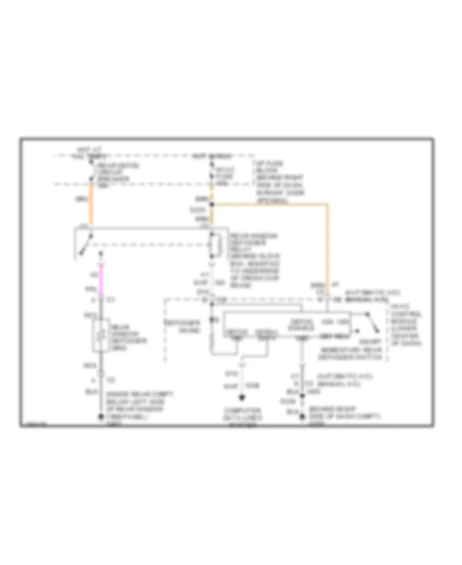
Подогрев стекол и зеркал
Электросхема подогрева стекол и зеркал для Buick Regal GS 2004
 https://portal-diagnostov.com/license.html
Automotive Electricians Portal FZCO
Automotive Electricians Portal FZCO
https://portal-diagnostov.com/license.html
https://portal-diagnostov.com/license.html
Automotive Electricians Portal FZCO
Automotive Electricians Portal FZCOЭлектросхема подогрева стекол и зеркал для Buick Regal GS 2004 - Список элементов:
- (automatic a/c) (manual a/c)
- (behind right side of dash compt) g200
- (inside rear compt, below left side of rear window trim panel) g401
- C1 k c2
- Computer data lines system
- D12
- D15 d
- Def req
- Defog enable
- Defog ind
- Defogger on ind
- Gnd
- Hot at all times
- Hot in run
- Hvac control module (lower center of dash)
- Hvac fuse 10a
- I/p fuse block (behind right side of dash, in right door opening)
- Ign
- Nca
- On/off momentary rear defogger switch
- Rear defog circuit breaker 30a
- Rear window defogger grid
- Rear window defogger relay (behind glove box, mounted to underside of cross-car beam)
- S230
- S233
- Serial data
ПОДУШКИ БЕЗОПАСНОСТИ AIR BAG
Электросхема подушек безопасности SRS AirBag для Buick Regal GS 2004
 https://portal-diagnostov.com/license.html
Automotive Electricians Portal FZCO
Automotive Electricians Portal FZCO
https://portal-diagnostov.com/license.html
https://portal-diagnostov.com/license.html
Automotive Electricians Portal FZCO
Automotive Electricians Portal FZCOЭлектросхема подушек безопасности SRS AirBag для Buick Regal GS 2004 - Список элементов:
- (driver seat adjuster wiring harness, 20 cm from c311 breakout) s330
- (inside left door sill, forward of left front seat) g301
- A10
- A11
- A12
- A13
- A14
- A15
- A16
- A17
- A18
- Air bag fuse 10a
- Air bag warning indicator
- B11
- Body control module (bcm) (behind left side of dash, left of steering column)
- Case ground
- Class 2 (bcm) serial data
- Data link connector (dlc) (partial) (under left side of dash, right of steering column)
- G200 (behind right side of i/p compartment)
- Ground
- High control
- Hot in run, bulb test & start
- I/p fuse block (behind right side of dash, in right door opening)
- If equipped
- Ignition
- Ignition voltage
- Inflatable restraint i/p module
- Inflatable restraint sensing & diagnostic module (sdm) (below carpet, under right front seat)
- Inflatable restraint steering wheel module
- Inflatable restraint steering wheel module coil
- Instrument cluster
- Ipc class 2 serial data
- Left front inflatable restraint side impact module
- Left front inflatable restraint side impact sensor (at base of left "b" pillar)
- Logic
- Low control
- Nca
- Powertrain control module (pcm) (left front side of engine compartment, in air cleaner assembly)
- Seat belt switch
- Seat belt switch (part of driver's seat belt assembly)
- Serial data class 2
- Shorting bar
- Signal
- Solid state
- Splice pack sp205 (behind data link connector)
- Voltage
ПРЕДУПРЕЖДАЮЩИЕ СИСТЕМЫ
Электросхема предупреждающей системы для Buick Regal GS 2004
 https://portal-diagnostov.com/license.html
Automotive Electricians Portal FZCO
Automotive Electricians Portal FZCO
https://portal-diagnostov.com/license.html
https://portal-diagnostov.com/license.html
Automotive Electricians Portal FZCO
Automotive Electricians Portal FZCOЭлектросхема предупреждающей системы для Buick Regal GS 2004 - Список элементов:
- door ajar sw sig
- (below dash, right side of steering column) g203
- (close w/ key in ignition)
- (inside left door sill, forward of left front seat) g301
- Accessory voltage
- Ajar
- B10
- B11
- Bcm acc fuse 10a
- Bcm class 2 serial data
- Body control module (bcm) (behind left side of dash, left of steering column)
- Chime
- Class 2 serial data
- Crank signal, bcm clstr fuse 10a
- Crank voltage
- Door unlatch sw sig
- Door/trunk ind
- Driver door lock
- Driver seat belt switch (w/ 6 way driver seat adjuster) (part of driver's seat belt assembly)
- Exterior lps off input
- G201 (below dash, left side of steering column)
- G203 (below dash, right side of steering column)
- Ground
- Head
- Headlamp switch
- Hot at all times
- Hot in acc & run
- Hot in run & start
- Hot in start
- Hot in unlock run & start
- I/p fuse block (behind right side of dash, in right door opening)
- Ign o, cluster, pcm & bcm fuse 10a
- Ignition 0 voltage
- Ignition 1 voltage
- Ignition switch (in steering column)
- Instrument panel cluster (ipc)
- Interior lights system
- Key in ign sw sig
- Latched
- Left seat belt switch
- Logic
- Low tire ind
- Low tire press sw sig
- Lp park fuse 34 20a
- Nca
- Off
- Park
- Park brake on signal
- Park brake switch (on parking brake assembly)
- Pcm, bcm u/h fuse 10a
- Pnk
- Power distribution system
- Powertrain control module (pcm) (left front side of engine compt, in air cleaner assembly)
- S211
- S234
- S270
- S283
- S322
- S330
- S504
- Seat belt ind
- Serial data
- Sp205 (behind data link connector)
- Tan
- Tire reset switch
- Un- latched
- Underhood fuse block (mounted to right front strut tower)
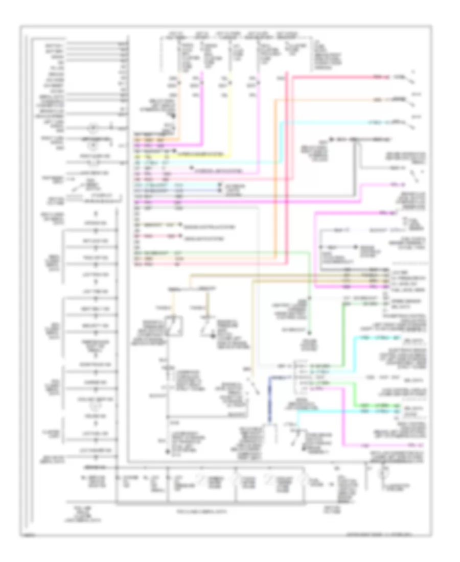
ПРИБОРНАЯ ПАНЕЛЬ
Электросхема панели приборов для Buick Regal GS 2004
 https://portal-diagnostov.com/license.html
Automotive Electricians Portal FZCO
Automotive Electricians Portal FZCO
https://portal-diagnostov.com/license.html
https://portal-diagnostov.com/license.html
Automotive Electricians Portal FZCO
Automotive Electricians Portal FZCOЭлектросхема панели приборов для Buick Regal GS 2004 - Список элементов:
- (below dash, left side of steering column) g201
- (below dash, right side of steering column)
- (lower right front of engine, on transaxle stud, left of starter)
- (regal)
- A10
- A11
- A12
- Air bag ind
- Antilock ind
- B10
- B11
- B12
- Battery
- Bcm class2 serial data
- Bcm or ipc serial data
- Body control module (bcm) (behind left side of dash, left of steering column)
- Brake fluid
- Brake fluid level switch (in brake fluid reservoir)
- Brake ind
- Century
- Change oil ind
- Charge ind
- Cluster fuse 10a
- Cluster logic
- Coolant temp ind
- Coolant temper- ature gauge
- Crank
- Crank sig, bcm, cluster fuse 10a
- Cruise control system
- Cruise ind
- D12
- Data link connector (dlc) (under left side of dash, right of steering column)
- Dic e/m
- Dic mode
- Dic reset
- Door/trunk ind
- Driver information center (dic) switch (regal)
- E/m
- Ebcm class2 serial data
- Electronic brake control module (ebcm) (at left side of engine compartment, near strut tower)
- Engine controls system
- Engine oil level switch (regal) (on bottom of engine b oil pan)
- Engine oil pressure (eop) switch (lower left side of engine, above starter)
- Engine oil pressure (eop) switch (lower right side of engine, b above starter)
- Exterior lights system
- Fuel gauge
- Fuel level sens
- Fuel level sensor
- Fuel pump & sender assembly (in fuel tank)
- G113
- G203
- Gnd
- Ground
- Headlights system
- High beam ind
- Hot at all times
- Hot in off, run or start
- Hot in run or start
- Hot in start
- Hot w/ park lamp on
- Hvac control module (lower center of dash)
- I/p fuse block (behind right side of dash, in right door opening)
- Ign
- Ign 0, cluster, pcm & bcm fuse 10a
- Ignition 1
- Ignition voltage
- Illumination (5 bulbs)
- Inflatable restraint sensing & diagnostic module (sdm) (below carpet, under right front seat)
- Instrument panel cluster (ipc)
- Int/ illum fuse 7.5a
- Interior lights system
- Left turn ind
- Left turn signal
- Low fuel ind
- Low oil ind
- Low oil pressure ind
- Low ref
- Low tire ind
- Low trac ind
- Low washer ind
- Mal- function indicator lamp (mil) (service engine soon)
- Mode
- Oil level sw
- Oil pressure sw
- On sig
- Park brake switch (on parking brake assembly)
- Pcm class 2 serial data
- Pcm class2 serial data
- Pcm, abs bcm & cluster logic serial data
- Performance shift ind (regal)
- Pk lps
- Pnk
- Powertrain control module (pcm) (left front side of engine compt, in air cleaner assembly)
- Radio, hvac, rfa, cluster, aldl fuse 15a
- Regal
- Reset
- Right turn ind
- Right turn signal
- S106
- S202
- S211
- S234
- S241
- S270
- S283
- S295 (ashtray jumper harness, inside ashtray, 5 cm from c242)
- S409 (10 cm from c405 breakout)
- Sdm class2 ign serial data
- Seat belt ind
- Security ind
- Serial data
- Service vehicle soon ind
- Sp205 (behind data link connector)
- Speed sensor
- Speedo- meter gauge
- Srl data
- Tacho- meter gauge
- Trac off ind
- Trip reset input
- Trip reset switch
- Underhood fuse block (mounted to right front c1 strut tower)
- Vehicle speed
- Vf display
- Windshield washer fluid
- Wiper/washer system
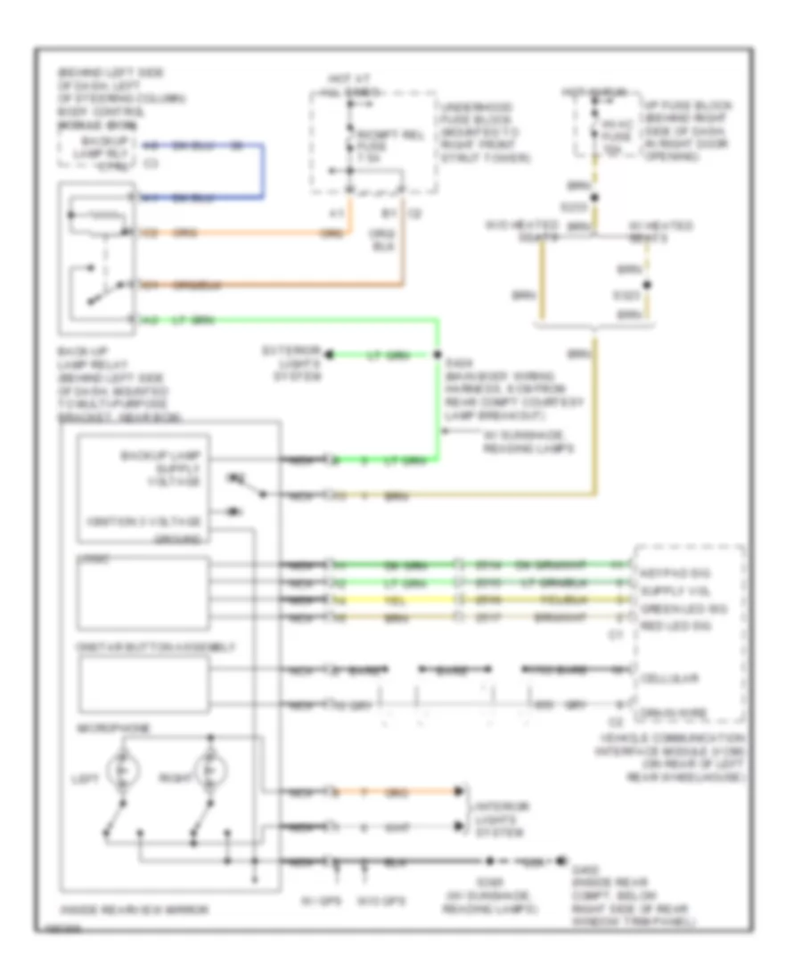
ПРИВОД ЗЕРКАЛ
Электросхема затемняющегося зеркала заднего вида для Buick Regal GS 2004
 https://portal-diagnostov.com/license.html
Automotive Electricians Portal FZCO
Automotive Electricians Portal FZCO
https://portal-diagnostov.com/license.html
https://portal-diagnostov.com/license.html
Automotive Electricians Portal FZCO
Automotive Electricians Portal FZCOЭлектросхема затемняющегося зеркала заднего вида для Buick Regal GS 2004 - Список элементов:
- (behind left side of dash, left of steering column) body control module (bcm)
- B1 c2
- Back-up lamp relay (behind left side of dash, mounted to multi-purpose bracket, near bcm)
- Backup lamp rly ctrl
- Bare
- Cellular
- Drain wire
- Exterior lights system
- G402 (inside rear compt, below right side of rear window trim panel)
- Green led sig
- Ground
- Hot at all times
- Hot in run
- Hvac fuse 10a
- I/p fuse block (behind right side of dash, in right door opening)
- Ignition 3 voltage
- Inside rearview mirror
- Interior lights system
- Keypad sig
- Left
- Logic
- Microphone
- Nca
- Off
- Onstar button assembly
- R/cmpt rel fuse 7.5a
- Red led sig
- Right
- S233
- S323
- S385 (w/ sunshade, reading lamps)
- S424 (main body wiring harness, 9 cm from rear compt courtesy lamp breakout)
- Underhood fuse block (mounted to right front strut tower)
- Vehicle communication interface module (vcim) (on rear of left rear wheelhouse)
- W/ gps
- W/ heated seats
- W/ sunshade, reading lamps
- W/o gps
- W/o heated seats
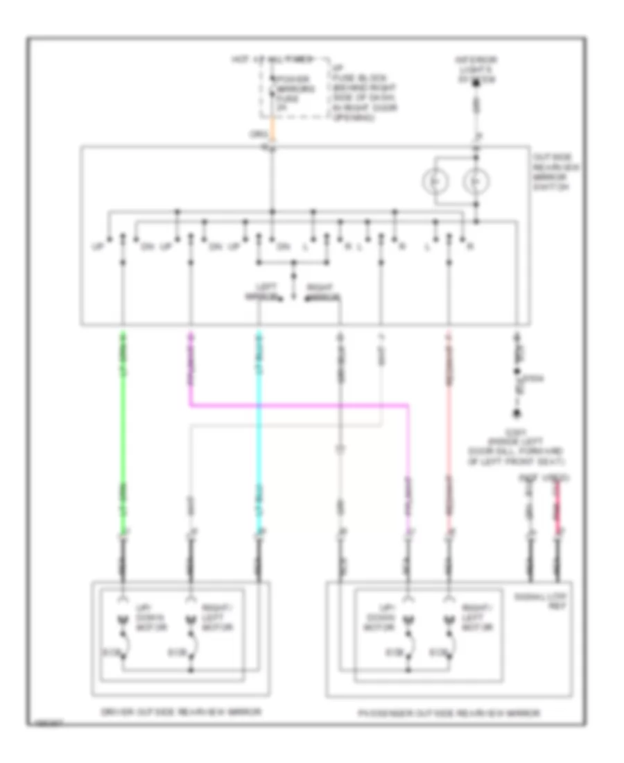
Электросхема привода зеркал для Buick Regal GS 2004
 https://portal-diagnostov.com/license.html
Automotive Electricians Portal FZCO
Automotive Electricians Portal FZCO
https://portal-diagnostov.com/license.html
https://portal-diagnostov.com/license.html
Automotive Electricians Portal FZCO
Automotive Electricians Portal FZCOЭлектросхема привода зеркал для Buick Regal GS 2004 - Список элементов:
- (not used) c12
- B12
- Driver outside rearview mirror
- Ecb
- G301 (inside left door sill, forward of left front seat)
- Hot at all times
- I/p fuse block (behind right side of dash, in right door opening)
- Interior lights system
- Left mirror
- Low ref
- Nca
- Outside rearview mirror switch
- Passenger outside rearview mirror
- Pnk
- Power mirrors fuse 2a
- Right mirror
- Right/ left motor
- S504
- Signal
- Up/ down motor
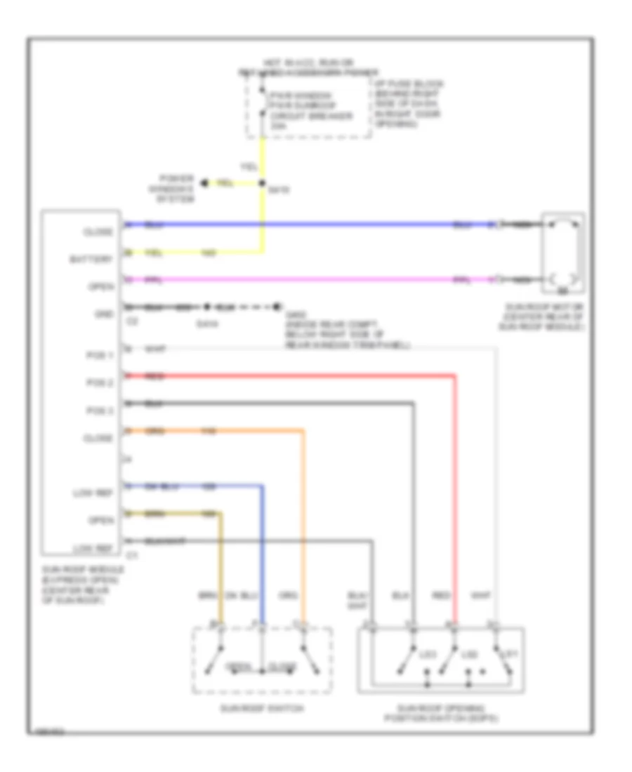
ПРИВОД ЛЮКА И КРЫШИ
Электросхема привода люка или крыши для Buick Regal GS 2004
 https://portal-diagnostov.com/license.html
Automotive Electricians Portal FZCO
Automotive Electricians Portal FZCO
https://portal-diagnostov.com/license.html
https://portal-diagnostov.com/license.html
Automotive Electricians Portal FZCO
Automotive Electricians Portal FZCOЭлектросхема привода люка или крыши для Buick Regal GS 2004 - Список элементов:
- Battery
- Close
- G402 (inside rear compt, below right side of rear window trim panel)
- Gnd
- Hot in acc, run or retained accessory power
- I/p fuse block (behind right side of dash, in right door opening)
- Low ref
- Ls1
- Ls2
- Ls3
- Nca
- Open
- Pos 1
- Pos 2
- Pos 3
- Power windows system
- Pwr window pwr sunroof circuit breaker 30a
- Red
- S410
- S414
- Sun roof module (express open) (center rear of sun roof)
- Sun roof motor (center rear of sun roof module)
- Sun roof opening position switch (sops)
- Sun roof switch
ПРИВОД СТЕКЛОПОДЪЕМНИКОВ
Электросхема стеклоподъемников для Buick Regal GS 2004
 https://portal-diagnostov.com/license.html
Automotive Electricians Portal FZCO
Automotive Electricians Portal FZCO
https://portal-diagnostov.com/license.html
https://portal-diagnostov.com/license.html
Automotive Electricians Portal FZCO
Automotive Electricians Portal FZCOЭлектросхема стеклоподъемников для Buick Regal GS 2004 - Список элементов:
- (body wiring harness, on floor, near center of vehicle, 20 cm from c325)
- Down
- Driver
- Driver master window switch
- Driver window motor (in driver's door)
- Express
- Express down module
- Front passenger
- Front passenger window motor
- Front passenger window switch
- G301 (inside left door sill, forward of left front seat)
- Hot in start or run or during rap
- I/p fuse block (behind right side of dash, in right door opening)
- Illumination lamp
- Interior lights system
- Left rear
- Left rear window motor
- Left rear window switch
- Lock out switch
- Pwr windows pwr sunroof circuit breaker 30a
- Right rear
- Right rear window motor (in right rear passenger door)
- Right rear window switch
- S307
- S410 (w/ sunroof)
- S604
- Tan
- Tan e
Противоугонная система Сигнализация
Электросхема противоугонной сигнализации для Buick Regal GS 2004
 https://portal-diagnostov.com/license.html
Automotive Electricians Portal FZCO
Automotive Electricians Portal FZCO
https://portal-diagnostov.com/license.html
https://portal-diagnostov.com/license.html
Automotive Electricians Portal FZCO
Automotive Electricians Portal FZCOЭлектросхема противоугонной сигнализации для Buick Regal GS 2004 - Список элементов:
- B10
- B12
- Batt
- Bcm gnd
- Bcm pwr fuse 10a
- Body control module (bcm) (behind left side of dash, left of steering column)
- Cluster fuse 10a
- Crank fuse 2 40a
- Crank relay ii
- Crank signal bcm, cluster fuse 10a
- Crank voltage
- Data link connector (dlc) (under left side of dash, right of steering column)
- F10
- G203 (below dash, right side of steering column)
- Hot at all times
- Hot in run or start
- Hot in run, bulb test or start
- Hot in start
- Hot in unlock, run or start
- I/p fuse block (behind right side of dash, in right door opening)
- Ign
- Ign 0
- Ign 0: cluster pcm & bcm fuse 10a
- Ign key sig
- Ign ref lo
- Ignition lock cylinder
- Ignition switch
- Instrument panel cluster
- K10
- K11
- Key
- Key in
- Key in sig
- Key out
- Logic
- M10
- M11
- Passkey ii system
- Pcm bcm u/h fuse 10a
- Pnk
- Powertrain control module (pcm) (left front side of engine compt, in air cleaner assembly)
- Resistor pellet
- S211
- S234
- S270
- Security ind
- Serial data
- Sp205 (behind data link connector)
- Starter (3.1l (vin j): left side of engine) (3.8l (vin k): lower front of engine compt)
- Starter rly ctrl
- Tan
- Underhood fuse block (mounted to right front strut tower)
СИСТЕМА АНТИБЛОКИРОВОЧНОЙ ТОРМОЗНОЙ СИСТЕМЫ ABS
Электросхема антиблокировочной тормозной системы АБС (ABS) для Buick Regal GS 2004
 https://portal-diagnostov.com/license.html
Automotive Electricians Portal FZCO
Automotive Electricians Portal FZCO
https://portal-diagnostov.com/license.html
https://portal-diagnostov.com/license.html
Automotive Electricians Portal FZCO
Automotive Electricians Portal FZCOЭлектросхема антиблокировочной тормозной системы АБС (ABS) для Buick Regal GS 2004 - Список элементов:
- A10
- A11
- Abs fuse 1 60a
- Abs fuse 10a
- Anti-lock fail ind
- B10
- B11
- B12
- Battery
- Body control module (bcm) (behind left side of dash left of steering column)
- Brake fluid level switch (in brake fluid reservoir)
- Brake ind
- Brake pressure modulator valve (bpmv)
- C10
- C11
- Cluster fuse 10a
- Data link connector (dlc) (under left side of dash, right of steering column)
- Delivered torque
- Desired torque
- Electronic brake control module (ebcm) (at left side of engine compartment, near strut tower)
- G113 (lower right front of engine, on transaxle stud left of starter)
- G171 (left side of engine compartment, below master cylinder)
- G203 (below dash, right side of steering column)
- Ground
- Hot at all times
- Hot in run or start
- Hot in run, bulb test or start
- I/p fuse block (behind right side of dash, in right door opening)
- Ignition
- Instrument panel cluster (ipc)
- Interior lights system
- Left front wheel spd (hi)
- Left front wheel spd (lo)
- Left front wheel speed sensor (wss) (on left front wheel hub assembly)
- Left rear wheel spd (hi)
- Left rear wheel spd (lo)
- Left rear wheel speed sensor (wss) (on left rear wheel hub assembly)
- Low trac ind
- Nca
- Pnk
- Powertrain control module (pcm) (left front side of engine compartment, in air cleaner assemble)
- Pump motor
- Red
- Regal
- Right front wheel spd (hi)
- Right front wheel spd (lo)
- Right front wheel speed sensor (wss) (on right front wheel hub assembly)
- Right rear wheel spd (hi)
- Right rear wheel spd (lo)
- Right rear wheel speed sensor (wss) (on right rear wheel hub assembly)
- S205 (i/p wiring harness, below dash, near c201, 14 cm from g201 breakout)
- S211
- Serial data signal
- Sp205 (behind data link connector)
- Stop lamp sw out
- Stop lamp switch (on brake pedal support bracket)
- Stop lamps fuse 15a
- Tan
- Trac off ind
- Traction control switch (regal)
- Underhood fuse block (mounted to right front strut tower)
- Vent tube
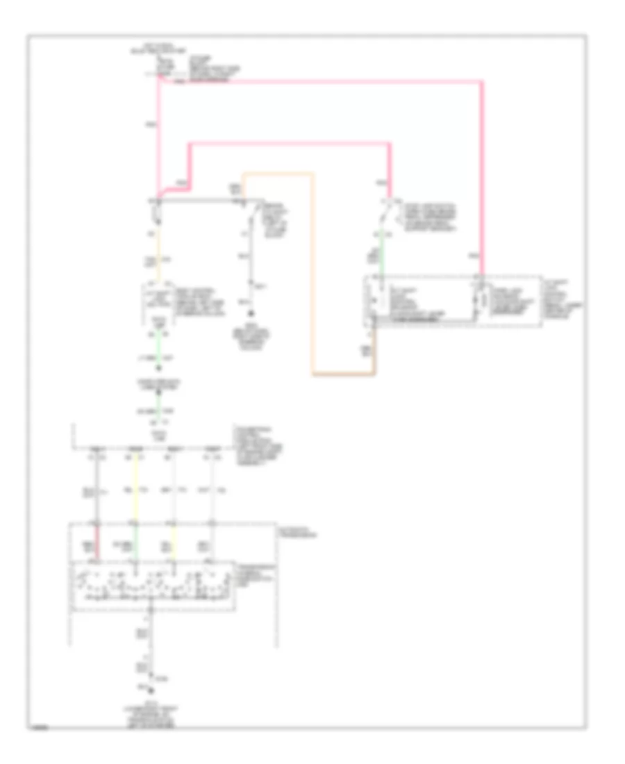
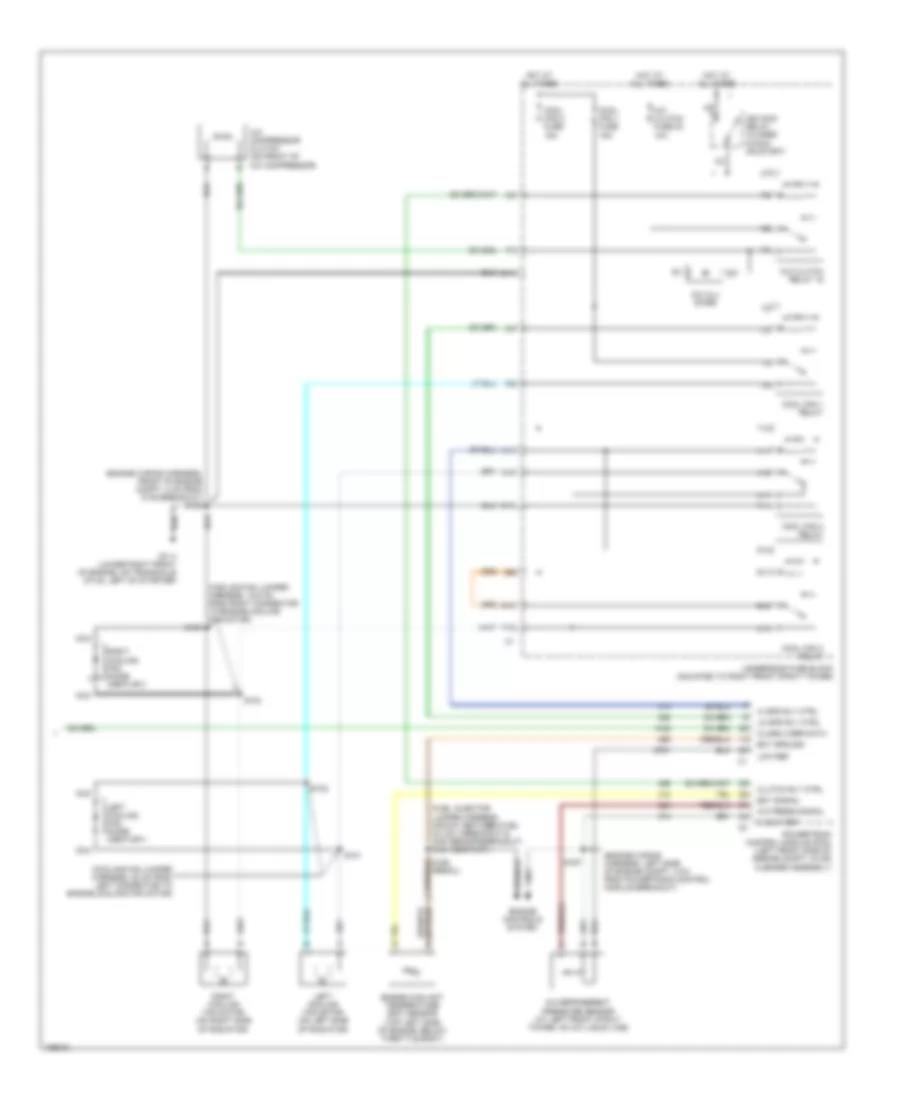
СИСТЕМА КОНДИЦИОНЕРА
Электросхема кондиционера (1 из 2) для Buick Regal GS 2004
 https://portal-diagnostov.com/license.html
Automotive Electricians Portal FZCO
Automotive Electricians Portal FZCO
https://portal-diagnostov.com/license.html
https://portal-diagnostov.com/license.html
Automotive Electricians Portal FZCO
Automotive Electricians Portal FZCOЭлектросхема кондиционера (1 из 2) для Buick Regal GS 2004 - Список элементов:
- (behind right side of dash compt) g200
- (i/p wiring harness, 18 cm from radio breakout) s230
- (i/p wiring harness, 4 cm left of hvac control module breakout)
- (i/p wiring harness, behind center of dash, 4 cm from radio breakout)
- (i/p wiring harness, right side of steering column, 19 cm from radio breakout)
- (lower center of dash) hvac control module
- (on right side of hvac module) vacuum control assembly
- 5 v ref
- A/c solenoid
- Air temp dr ctrl
- Ambient outside air temperature sensor (front of radiator support)
- Ambient temp sig
- Battery
- Bi-level solenoid
- Blower motor (behind right side of dash, in hvac module)
- Blower motor control processor (behind right side of dash, in hvac module)
- Blower speed ctrl
- C10
- C11
- C12
- C13
- C14
- C15
- C16
- Class 2 serial data
- Cntrl in
- D10
- D11
- D12
- D13
- D14
- D15
- D16
- Data link connector (dlc) (under left side of dash, right of steering column)
- Def mode sol ctrl
- Defrost solenoid
- Gnd
- Heater solenoid
- High blower fuse 30a
- Hot at all times
- Hot in run
- Hvac fuse 10a
- I/p fuse block (behind right side of dash, in right door opening)
- Ign 3 voltage
- Inside air temperature sensor (at left side of dash, below instrument cluster)
- Inside temp sig
- Interior lights system
- Ip dim sw sig
- Left air temperature actuator (left side of hvac module)
- Low ref
- Lt temp dr pos
- Lwr mode sol ctrl
- Mix-blnd sol ctrl
- Radio, hvac, rfa, cluster aldl fuse 15a
- Rear defogger system
- Recirc sol ctrl
- Recirc solenoid
- Red
- Right air temperature actuator (right side of hvac module)
- Rr defog rly ctrl
- Rt temp dr ctrl
- Rt temp dr pos
- S202
- S231 (i/p wiring harness, 33 cm from hvac control module connector)
- S233
- S258
- Solid state
- Sp205 (behind data link connector)
- Sun load sig
- Sunload sensor (on top right side of dash, near defogger outlet)
- Tan
- Upper mode sol ctrl
Электросхема кондиционера (2 из 2) для Buick Regal GS 2004
 https://portal-diagnostov.com/license.html
Automotive Electricians Portal FZCO
Automotive Electricians Portal FZCO
https://portal-diagnostov.com/license.html
https://portal-diagnostov.com/license.html
Automotive Electricians Portal FZCO
Automotive Electricians Portal FZCOЭлектросхема кондиционера (2 из 2) для Buick Regal GS 2004 - Список элементов:
- (century)
- (cooling fan jumper harness, 19.5 cm from right connector to engine cooling fan motor)
- (cooling fan jumper harness, 20 cm from left connector to engine cooling fan motor)
- (engine wiring harness, front of engine compt, 4 cm from c105 breakout) s105
- (engine wiring harness, left side of engine compt, 4 cm from powertrain control module breakout)
- (fuel injector jumper harness, midway between fuel inj no 3 breakout & map sensor breakout)
- (top left side of engine, below throttle body)
- 5 volt ref
- A/c compressor clutch (on front of a/c compressor)
- A/c clu diode
- A/c clutch fuse 23 10a
- A/c clutch relay 15
- A/c press signal
- A/c refrigerent pressure sensor (at left front strut tower, on a/c liquid line)
- A10
- A11
- C11
- Class 2 ser data
- Clutch rly ctrl
- Cool fan 1 fuse 15a
- Cool fan 2 fuse 15a
- Cool fan 1 relay
- Cool fan 2 relay
- Cool fan 3 relay
- E10
- Ect ground
- Ect signal
- Engine controls system
- Engine coolant temperature (ect) sensor
- F12
- G113 (lower right front of engine, on transaxle stud, left of starter)
- Hi spd rly ctrl
- Hot at all times
- Ign main relay (closed in run or start)
- Left cooling fan diode (century)
- Left cooling fan motor (on left side of radiator)
- Lo spd rly ctrl
- Low ref
- Nca
- P10
- P11
- Powertrain control module (pcm) (left front side of engine compt, in air cleaner assembly)
- R10
- R11
- Right cooling fan diode (century)
- Right cooling fan motor (on right side of radiator)
- S101
- S102
- S103
- S104
- S121
- S167
- S186 (regal)
- T10
- T11
- U11
- Underhood fuse block (mounted to right front strut tower)
- V10
- V11
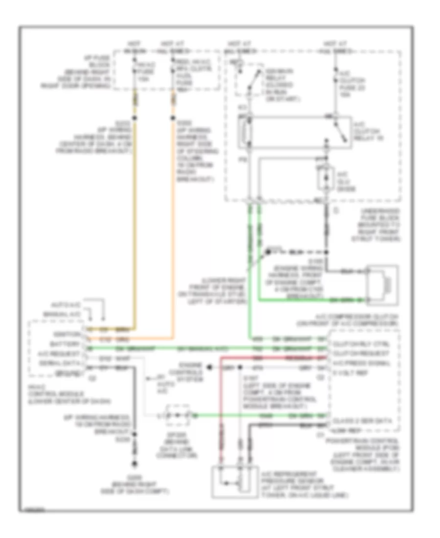
Электросхема компрессора для Buick Regal GS 2004
 https://portal-diagnostov.com/license.html
Automotive Electricians Portal FZCO
Automotive Electricians Portal FZCO
https://portal-diagnostov.com/license.html
https://portal-diagnostov.com/license.html
Automotive Electricians Portal FZCO
Automotive Electricians Portal FZCOЭлектросхема компрессора для Buick Regal GS 2004 - Список элементов:
- (i/p wiring harness, 18 cm from radio breakout)
- (lower right front of engine, on transaxle stud, left of starter)
- (w/ manual a/c)
- 5 volt ref
- A/c clu diode
- A/c clutch fuse 23 10a
- A/c clutch relay 15
- A/c compressor clutch (on front of a/c compressor)
- A/c press signal
- A/c refrigerent pressure sensor (at left front strut tower, on a/c liquid line)
- A/c request
- Auto a/c
- Battery
- C11
- C12
- Class 2 ser data
- Clutch request
- Clutch rly ctrl
- D12
- Engine controls system
- G113
- G200 (behind right side of dash compt)
- Ground
- Hot at all times
- Hot in run
- Hvac control module (lower center of dash)
- Hvac fuse 10a
- I/p fuse block (behind right side of dash, in right door opening)
- Ign main relay (closed in run or start)
- Ignition
- Low ref
- Manual a/c
- Powertrain control module (pcm) (left front side of engine compt, in air cleaner assembly)
- Rdo, hvac, rfa clstr, aldl fuse 10a
- S105 (engine wiring harness, front of engine compt, 4 cm from c105 breakout)
- S167 (left side of engine compt, 4 cm from powertrain control module breakout)
- S202 (i/p wiring harness, right side of steering column, 19 cm from radio breakout)
- S230
- S233 (i/p wiring harness, behind center of dash, 4 cm from radio breakout)
- Serial data
- Sp205 (behind data link connector)
- Underhood fuse block (mounted to right front strut tower)
- W/ auto a/c
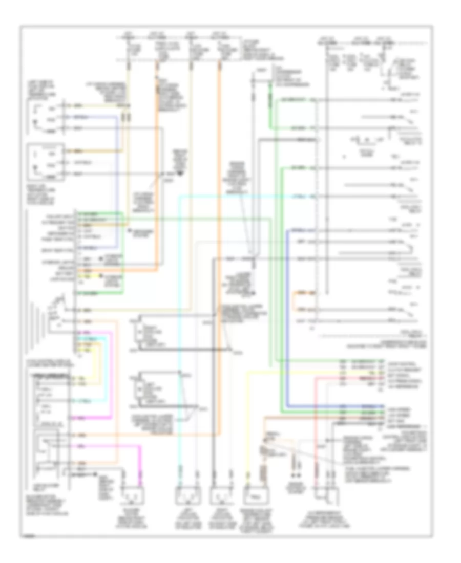
Электросхема кондиционера с ручный управлением для Buick Regal GS 2004
 https://portal-diagnostov.com/license.html
Automotive Electricians Portal FZCO
Automotive Electricians Portal FZCO
https://portal-diagnostov.com/license.html
https://portal-diagnostov.com/license.html
Automotive Electricians Portal FZCO
Automotive Electricians Portal FZCOЭлектросхема кондиционера с ручный управлением для Buick Regal GS 2004 - Список элементов:
- (behind right side of dash compt) g200
- (cooling fan jumper harness, 19.5 cm from right connector to engine cooling fan motor)
- (cooling fan jumper harness, 20 cm from left connector to engine cooling fan motor)
- (engine wiring harness, front of engine compt, 4 cm from c105 breakout)
- (engine wiring harness, left side of engine compt, 4 cm from powertrain control module breakout)
- (fuel injector jumper harness, midway between fuel inj no 3 breakout & map sensor breakout)
- (i/p wiring harness, 18 cm from radio breakout)
- (i/p wiring harness, behind center of dash, 4 cm from radio breakout)
- (left side of hvac module) left air temperature actuator
- (on left side of radiator)
- (on right side of radiator)
- (regal) s186
- (top left side of engine, below throttle body)
- +5v reference
- A/c compressor clutch (on front of a/c compressor)
- A/c clu diode
- A/c clutch fuse 23 10a
- A/c clutch relay 15
- A/c press signal
- A/c refrigerant pressure sensor (at left front strut tower, on a/c liquid line)
- A/c request sig
- A10
- A11
- Battery
- Blower motor (behind right side of dash, in hvac module)
- Blower motor resistor assembly (under right side of dash, in right side of hvac module)
- C11
- Clutch request
- Comp control
- Cool fan 1 fuse 15a
- Cool fan 2 fuse 15a
- Cool fan 1 relay
- Cool fan 2 relay
- Cool fan 3 relay
- Defogger on
- Defogger system
- Drvr temp ctrl
- E10
- Ect gnd
- Ect signal
- Engine controls system
- Engine coolant temperature (ect) sensor
- F12
- Fan off input
- G200 (behind right side of dash compt)
- Gnd
- Ground
- High blower fuse 30a
- High blower relay
- High speed
- Hot at all times
- Hot in run
- Hvac control module (lower center of dash)
- Hvac fuse 10a
- I/p fuse block (behind right side of dash, in right door opening)
- Ign
- Ign main relay (closed in run or start)
- Ignition
- Interior lights
- Interior lights system
- Lamp dim sig
- Left cooling fan diode (century)
- Left cooling fan motor
- Low blower fuse 20a
- Low reference
- Low speed
- Nca
- Off
- P10
- P11
- Pass temp ctrl
- Pos
- Powertrain control module (pcm) (left front side of engine compt, in air cleaner assembly)
- R10
- R11
- Rdo, hvac, rfa clstr, aldl fuse 10a
- Right air temperature actuator (right side of hvac module)
- Right cooling fan diode (century)
- Right cooling fan motor
- S101
- S102
- S103
- S104
- S105
- S167
- S230
- S233
- T10
- T11
- Tan
- Thermal breakers
- U11
- Underhood fuse block (mounted to right front strut tower)
- V10
- V11
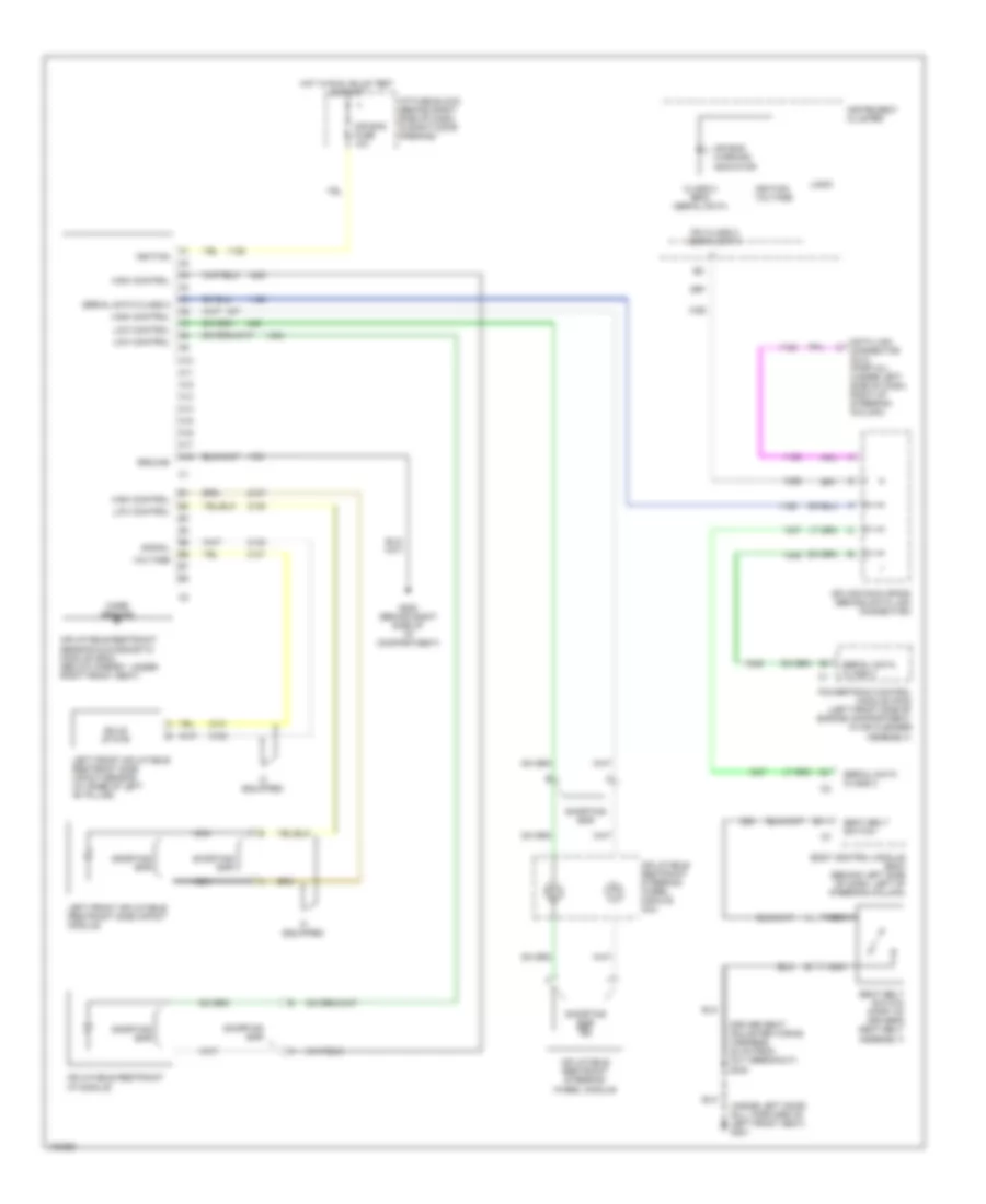
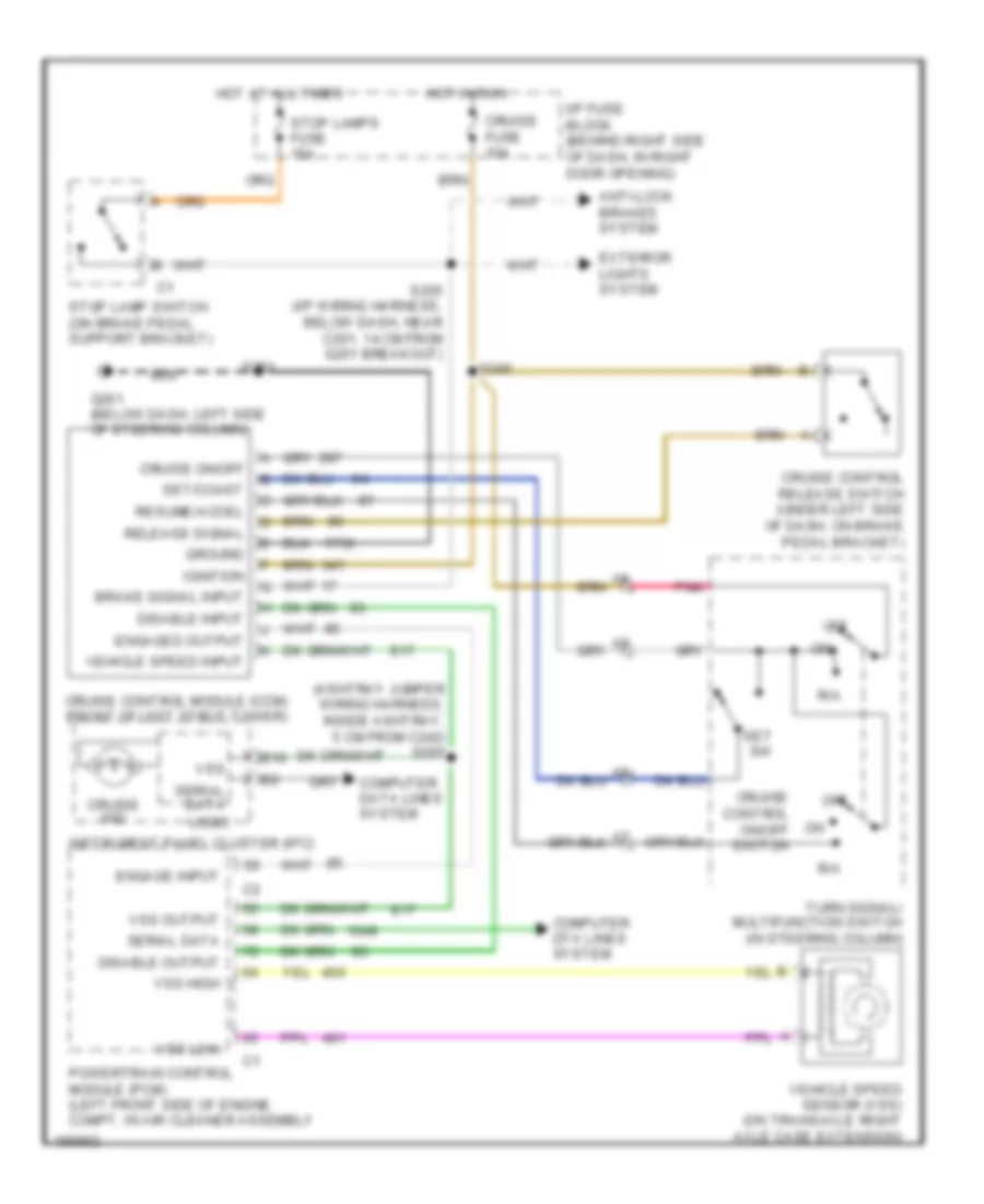
СИСТЕМА КРУИЗКОНТРОЛЯ
Электросхема системы круизконтроля для Buick Regal GS 2004
 https://portal-diagnostov.com/license.html
Automotive Electricians Portal FZCO
Automotive Electricians Portal FZCO
https://portal-diagnostov.com/license.html
https://portal-diagnostov.com/license.html
Automotive Electricians Portal FZCO
Automotive Electricians Portal FZCOЭлектросхема системы круизконтроля для Buick Regal GS 2004 - Список элементов:
- (ashtray jumper wiring harness, inside ashtray, 5 cm from c242) s295
- Anti-lock brakes system
- B10
- Brake signal input
- Computer data lines system
- Computer dta lines system
- Cruise control module (ccm) (front of left strut tower)
- Cruise control on/off switch
- Cruise control release switch (under left side of dash, on brake pedal bracket)
- Cruise fuse 10a
- Cruise ind
- Cruise on/off
- Disable input
- Disable output
- Engage input
- Engaged output
- Exterior lights system
- G201 (below dash, left side of steering column)
- Ground
- Hot at all times
- Hot in run
- I/p fuse block (behind right side of dash, in right door opening)
- Ignition
- Instrument panel cluster (ipc)
- Logic
- Off
- Pnk
- Powertrain control module (pcm) (left front side of engine compt, in air cleaner assembly
- R/a
- Release signal
- Resume/accel
- S205 (i/p wiring harness, below dash, near c201, 14 cm from g201 breakout)
- S240
- S283
- Serial data
- Set sw
- Set/coast
- Stop lamp switch (on brake pedal support bracket)
- Stop lamps fuse 15a
- Turn signal/ multifunction switch (in steering column)
- Vehicle speed input
- Vehicle speed sensor (vss) (on transaxle right axle case extension)
- Vss
- Vss high
- Vss low
- Vss output
СИСТЕМА ОХЛАЖДЕНИЯ
Электросхема системы охлаждения для Buick Regal GS 2004
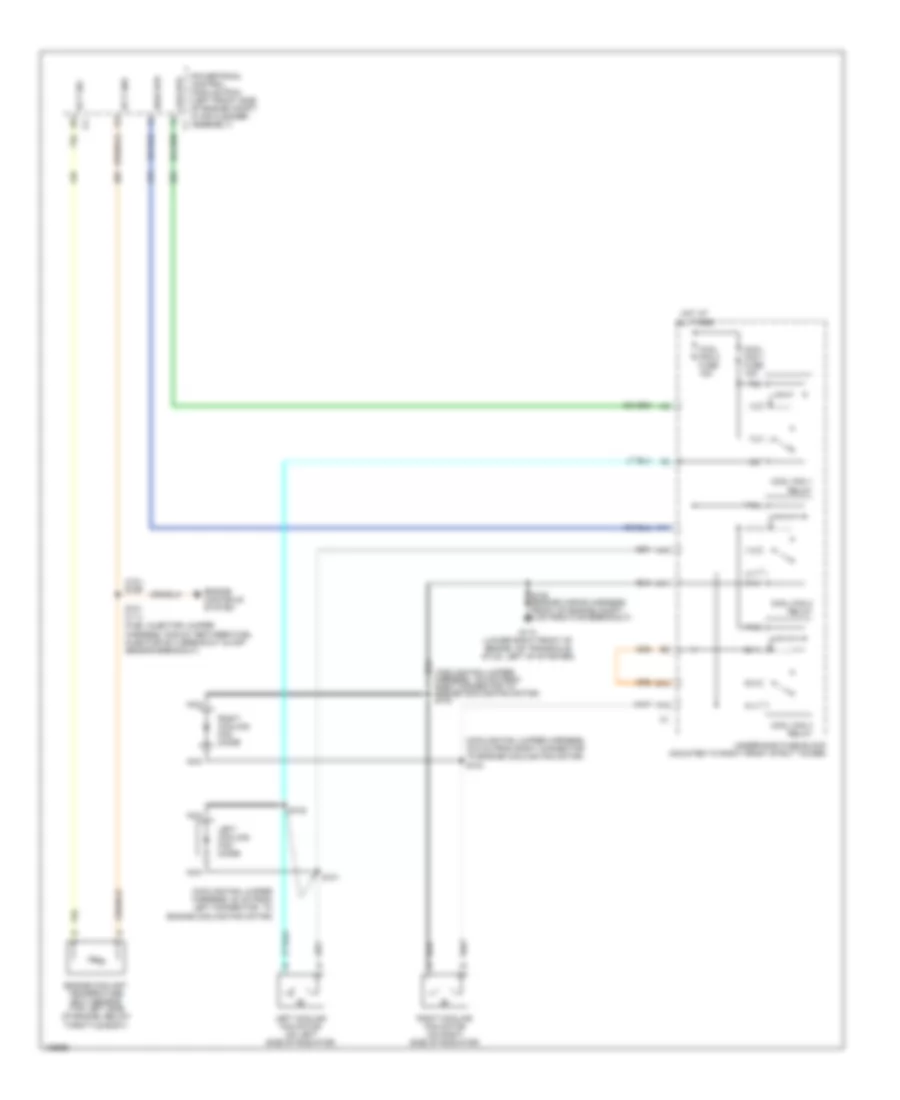 https://portal-diagnostov.com/license.html
Automotive Electricians Portal FZCO
Automotive Electricians Portal FZCO
https://portal-diagnostov.com/license.html
https://portal-diagnostov.com/license.html
Automotive Electricians Portal FZCO
Automotive Electricians Portal FZCOЭлектросхема системы охлаждения для Buick Regal GS 2004 - Список элементов:
- (3.8l) s186
- (cooling fan jumper harness, 19.5 cm from right connector to engine cooling fan motor) s103
- (cooling fan jumper harness, 19.5 cm from right connector to engine cooling fan motor) s104
- (cooling fan jumper harness, 20 cm from left connector to engine cooling fan motor)
- (fuel injector jumper harness, midway between fuel injector no 3 breakout & map sensor breakout)
- A10
- A11
- C11
- Cool fan 1 fuse 15a
- Cool fan 2 fuse 15a
- Cool fan 1 relay
- Cool fan 2 relay
- Cool fan 3 relay
- E10
- Ect gnd
- Ect sig
- Engine controls system
- Engine coolant temperature (ect) sensor (top left side of engine, below throttle body)
- F12
- G113 (lower right front of engine, on transaxle stud, left of starter)
- High spd
- Hot at all times
- Left cooling fan diode
- Left cooling fan motor (on left side of radiator)
- Low spd
- Nca
- P10
- P11
- Powertrain control module (pcm) (left front side of engine compt, in air cleaner assembly)
- R10
- R11
- Right cooling fan diode
- Right cooling fan motor (on right side of radiator)
- S101
- S102
- S105 (engine wiring harness, front of engine compt, 4 cm from c105 breakout)
- S121 (3.1l)
- T10
- T11
- U11
- Underhood fuse block (mounted to right front strut tower)
- V10
- V11
СИСТЕМА ПЕРЕДАЧИ ДАННЫХ
Электросхема линии передачи данных CAN для Buick Regal GS 2004
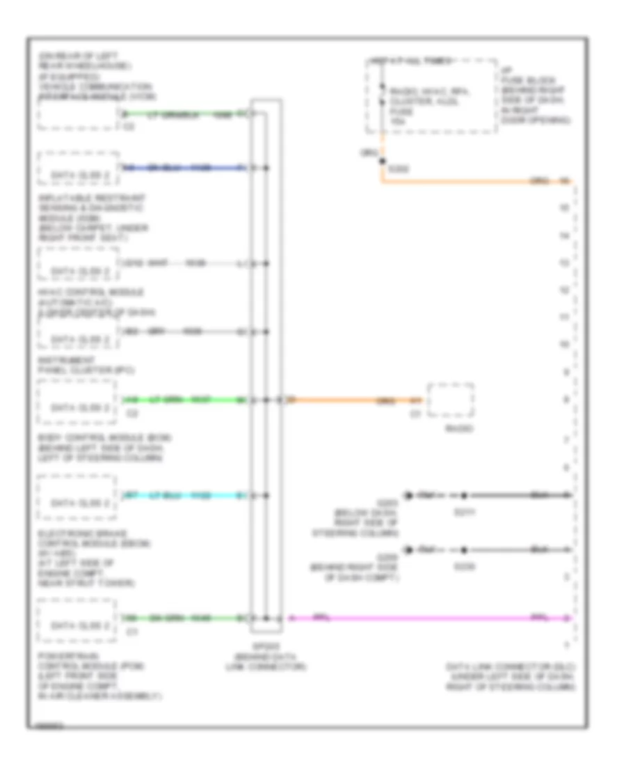 https://portal-diagnostov.com/license.html
Automotive Electricians Portal FZCO
Automotive Electricians Portal FZCO
https://portal-diagnostov.com/license.html
https://portal-diagnostov.com/license.html
Automotive Electricians Portal FZCO
Automotive Electricians Portal FZCOЭлектросхема линии передачи данных CAN для Buick Regal GS 2004 - Список элементов:
- (on rear of left rear wheelhouse) (if equipped) vehicle communication interface module (vicm)
- Body control module (bcm) (behind left side of dash, left of steering column)
- D12
- Data clss 2
- Data link connector (dlc) (under left side of dash, right of steering column)
- Electronic brake control module (ebcm) (w/ abs) (at left side of engine compt, near strut tower)
- G200 (behind right side of dash compt)
- G203 (below dash, right side of steering column)
- Hot at all times
- Hvac control module (automatic a/c) (lower center of dash)
- I/p fuse block (behind right side of dash, in right door opening)
- Inflatable restraint sensing & diagnostic module (sdm) (below carpet, under right front seat)
- Instrument panel cluster (ipc)
- Powertrain control module (pcm) (left front side of engine compt, in air cleaner assembly)
- Radio
- Radio, hvac, rfa, cluster, aldl fuse 15a
- S202
- S211
- S230
- Sp205 (behind data link connector)
СИСТЕМА УПРАВЛЕНИЯ ДВИГАТЕЛЯ
3.8L VIN 1
3.8L VIN 1, Электросхема системы управления двигателем (1 из 4) для Buick Regal GS 2004
 https://portal-diagnostov.com/license.html
Automotive Electricians Portal FZCO
Automotive Electricians Portal FZCO
https://portal-diagnostov.com/license.html
https://portal-diagnostov.com/license.html
Automotive Electricians Portal FZCO
Automotive Electricians Portal FZCO3.8L VIN 1, Электросхема системы управления двигателем (1 из 4) для Buick Regal GS 2004 - Список элементов:
- (ign harn, top of eng, near ign control module)
- (not used)
- (on trans- axle stud)
- (pin 11 not used)
- (pin 14-15 not used)
- (pin 21-27 not used)
- (pin 40-42 not used)
- (pin 49-52 not used)
- (pin 66-67 not used)
- (right side of engine, on ignition contrl module bracket)
- (vin 1)
- 1-2 ss valve control
- 18x ref signal
- 2-3 ss valve control
- 3x ref signal
- A/t iss sensor high
- A/t iss sensor low
- Abs system
- Camshaft position sensor (cmp) (front of engine)
- Cmp signal
- Cooling fans system
- Crankshaft position sensor (ckp) (front of eng, behind harmonic balancer)
- Cruise control system
- Cruise disable output
- Data link connector (dlc) (under left side of dash, right of steering column)
- Ecm fuse 22 10a
- Egr val control (gnd)
- Elek ign fuse 25 15a
- Eng emis fuse 30 10a
- Evap purge val control
- F/injr fuse 28 15a
- Fuel inj 1 control
- Fuel inj 2 control
- Fuel inj 4 control
- Fuel inj 5 control
- Fuel inj 6 control
- G111
- G113
- High speed fans control
- Hos1 low
- Hos2 low
- Hot at all times
- Hot in off, run, or start
- Hot in run or start
- I/p fuse block (behind right side of dash, in right door opening)
- Iac coil b high
- Iat sensor ground
- Ic control
- Ign 0 fuse 10a
- Ignition control
- Ignition control module (icm) (top front of eng)
- Ignition wake up power
- Knock sensor bank 1 (left side of eng, in front of starter)
- Knock sensor bank 2 (right side of eng, below exhaust manifold)
- Knock sensor signal 1
- Knock sensor signal 2
- Low ref
- Low speed fans control
- Maf signal
- Map sensor
- Pcm ground
- Pnk
- Pnk p
- Power (battery)
- Powertrain control module (pcm) (left front side of eng compt, in air cleaner assembly)
- Ref low
- Requested torque sig
- S106
- S144
- S145
- S270
- Sensor grd
- Sensor ground
- Serial data (class 2)
- Spark plugs
- Splice pack sp205
- Tcc brake switch input
- Tp sensor
- Tr switch input b
- Underhood fuse block (mounted to right strut tower)
- Vss high
- Vss low
- Vss output
3.8L VIN 1, Электросхема системы управления двигателем (2 из 4) для Buick Regal GS 2004
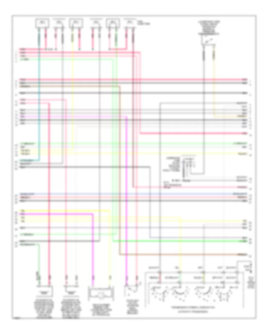 https://portal-diagnostov.com/license.html
Automotive Electricians Portal FZCO
Automotive Electricians Portal FZCO
https://portal-diagnostov.com/license.html
https://portal-diagnostov.com/license.html
Automotive Electricians Portal FZCO
Automotive Electricians Portal FZCO3.8L VIN 1, Электросхема системы управления двигателем (2 из 4) для Buick Regal GS 2004 - Список элементов:
- (lower right side of eng, above transaxle) engine oil pressure indicator switch
- (on transaxle stud)
- Automatic transmission
- Evaporative emissions (evap) canister purge solenoid valve (top left side of eng, near center of valve cover)
- Evaporative emissions (evap) canister vent solenoid valve (behind left side of rear fascia splash shield, in wheelwell)
- Fuel injectors
- G113
- G113 (on trans- axle stud)
- Pnk
- S106
- S109
- Stoplight switch (on brake pedal support bracket)
- Transmission internal mode switch
- Underhood fuse block (mounted to right strut tower)
- Vehicle speed sensor (vss) (lower right side of eng compt, on transaxle)
3.8L VIN 1, Электросхема системы управления двигателем (3 из 4) для Buick Regal GS 2004
 https://portal-diagnostov.com/license.html
Automotive Electricians Portal FZCO
Automotive Electricians Portal FZCO
https://portal-diagnostov.com/license.html
https://portal-diagnostov.com/license.html
Automotive Electricians Portal FZCO
Automotive Electricians Portal FZCO3.8L VIN 1, Электросхема системы управления двигателем (3 из 4) для Buick Regal GS 2004 - Список элементов:
- (eng harn, near 4 cm from pcm breakout)
- (in exhaust system, rear of catalytic converter) heated oxygen sensor 2 (ho2s 2)
- (in right side exhaust manifold) heated oxygen sensor 1 (ho2s 1)
- (on bottom of engine oil pan) engine oil level indicator switch
- (on throttle body assembly) idle air control (iac) valve
- (top rear of eng, part of throttle body assembly) mass airflow (maf) sensor
- A/c refrigerant pressure sensor (on left side of eng compt, on accumulator)
- B12
- D pnk
- Engine coolant temperature (ect) sensor (top left side of eng, below throttle body)
- Exhaust gas recirculation (egr) valve (top rear of eng, near throttle body)
- Fuel tank pressure sensor (in fuel tank)
- Hot in run, bulb test or start
- Instrument cluster
- Intake air temperature (iat) sensor (left front of eng compt, in air cleaner duct)
- Malfunction indicator lamp
- Manifold absolute pressure (map) sensor (top of engine, on front of intake manifold)
- Nca
- Oxy sen fuse 29 15a
- Pnk
- S167
- S186
- S187
- Supercharger boost control solenoid (vin 1) (top left rear of eng)
- Tan
- Throttle position (tp) sensor (on throttle body assembly)
- Trans fuse 26 10a
- Underhood fuse block (mounted to right strut tower)
3.8L VIN 1, Электросхема системы управления двигателем (4 из 4) для Buick Regal GS 2004
 https://portal-diagnostov.com/license.html
Automotive Electricians Portal FZCO
Automotive Electricians Portal FZCO
https://portal-diagnostov.com/license.html
https://portal-diagnostov.com/license.html
Automotive Electricians Portal FZCO
Automotive Electricians Portal FZCO3.8L VIN 1, Электросхема системы управления двигателем (4 из 4) для Buick Regal GS 2004 - Список элементов:
- (body harn, under rear seat)
- (fuel pump prime terminal)
- (on transaxle stud)
- (pin 12-15 not used)
- (pin 31-32 not used)
- (pin 40-41 not used)
- (pin 51-54 not used)
- (pin 6 & 8 not used)
- (pin 62 & 64-65 not used)
- (pin 70-75 not used)
- (right side of rear shelf) g402
- (vin 1)
- 1-2 shift solenoid
- 2-3 shift solenoid
- 5v ref a
- A/c compress clutch rly
- A/c refrig press signal
- A/c request signal
- A/c system
- A/t iss solenoid
- A11
- Anti-lock brakes system
- Automatic transaxle
- Automatic transaxle fluid pressure manual valve position switch
- Boost ctrl sol ctrl
- Cluster fuse 10a
- Crank
- Crank signal fuse 10a
- Cruise control system
- Cruise engaged input
- D10
- Delivered torque sig
- Ect sensor signal
- Egr pintle position signal
- Egr val ign positive volt
- Eng oil level ind in
- Eng oil press sensor sig
- Evap can vent sol
- F/pmp fuse 35 15a
- F/pmp spd cont relay (vin 1 w/ fog lights)
- F/pump relay
- Fluid temp sensor
- Fuel inj 3 control
- Fuel level sensor
- Fuel level sensor input
- Fuel pump
- Fuel pump relay control
- Fuel tank
- Fuel tank press signal
- G113
- Gen terminal l output
- Ho2s 1 htr
- Ho2s 1 signal
- Ho2s 2 htr
- Ho2s 2 signal
- Hot at all times
- Hot in run or start
- Hot in start
- I/p fuse block (behind right side of dash, in right door opening)
- Iac coil a high
- Iac coil a low
- Iac coil b low
- Iat sensor signal
- Ignition positive volt (2)
- Map sensor signal
- Mil control
- Pc sol valve high
- Pc sol valve low
- Pcm,bcm ign relay fuse 10a
- Pnk
- Powertrain control module (pcm) (left front side of eng compt, in air cleaner assembly)
- Ps solenoid
- Red
- S106
- S234
- S409
- Sensor ground
- Starter enable control
- Starting/ charging system
- Tan
- Tan b
- Tcc release switch input
- Tcc sol valve control
- Tcc solenoid
- Tft sensor signal
- Tp sens or signal
- Tr switch input a
- Tr switch input c
- Trans fluid press sw b
- Underhood accessory fuse block (mounted to right strut tower)
- Underhood fuse block (mounted to right strut tower)
3.8L ВИН К.
3.8L ВИН К, Электросхема системы управления двигателем (1 из 4) для Buick Regal GS 2004
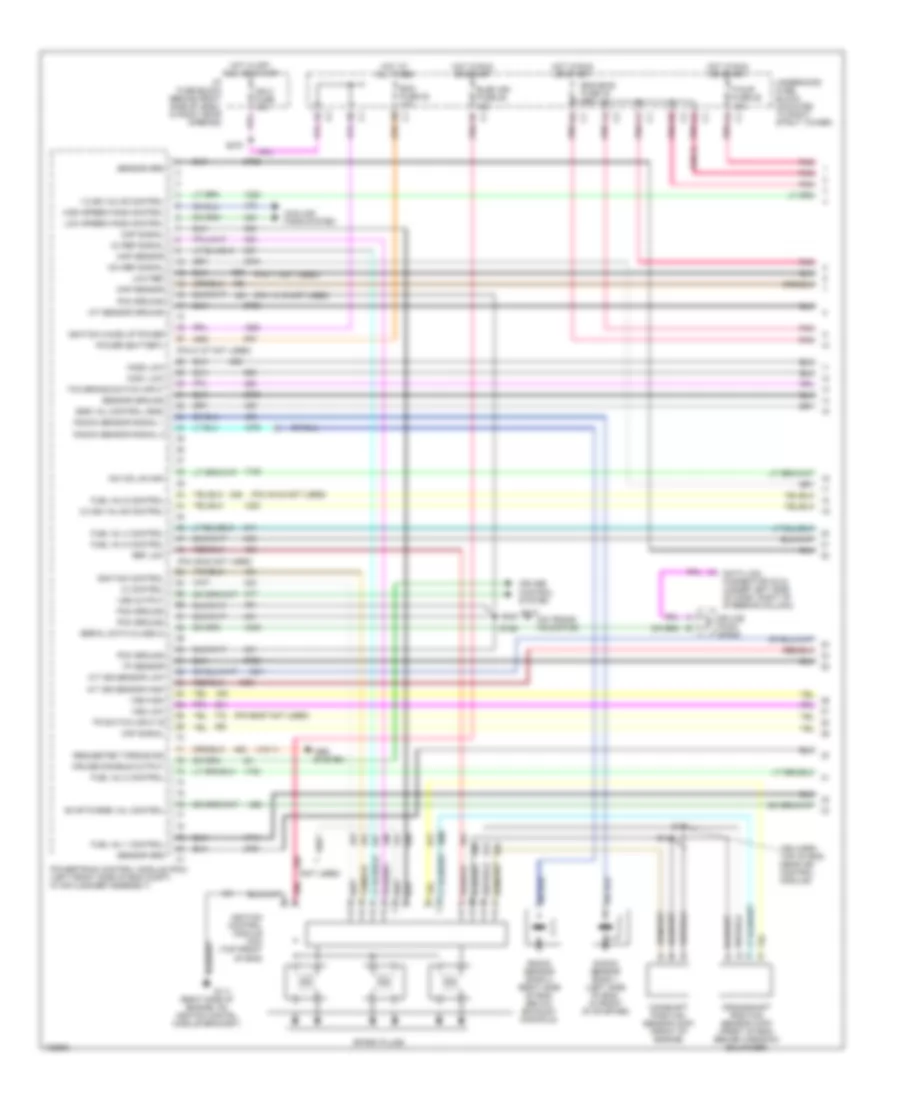 https://portal-diagnostov.com/license.html
Automotive Electricians Portal FZCO
Automotive Electricians Portal FZCO
https://portal-diagnostov.com/license.html
https://portal-diagnostov.com/license.html
Automotive Electricians Portal FZCO
Automotive Electricians Portal FZCO3.8L ВИН К, Электросхема системы управления двигателем (1 из 4) для Buick Regal GS 2004 - Список элементов:
- (ign harn, top of eng, near ign control module)
- (not used)
- (on trans- axle stud)
- (pin 11 not used)
- (pin 14-15 not used)
- (pin 21-27 not used)
- (pin 40-42 not used)
- (pin 49-52 not used)
- (pin 66-67 not used)
- (right side of engine, on ignition contrl module bracket)
- (vin 1)
- 1-2 ss valve control
- 18x ref signal
- 2-3 ss valve control
- 3x ref signal
- A/t iss sensor high
- A/t iss sensor low
- Abs system
- Camshaft position sensor (cmp) (front of engine)
- Cmp signal
- Cooling fans system
- Crankshaft position sensor (ckp) (front of eng, behind harmonic balancer)
- Cruise control system
- Cruise disable output
- Data link connector (dlc) (under left side of dash, right of steering column)
- Ecm fuse 22 10a
- Egr val control (gnd)
- Elek ign fuse 25 15a
- Eng emis fuse 30 10a
- Evap purge val control
- F/injr fuse 28 15a
- Fuel inj 1 control
- Fuel inj 2 control
- Fuel inj 4 control
- Fuel inj 5 control
- Fuel inj 6 control
- G111
- G113
- High speed fans control
- Hos1 low
- Hos2 low
- Hot at all times
- Hot in off, run, or start
- Hot in run or start
- I/p fuse block (behind right side of dash, in right door opening)
- Iac coil b high
- Iat sensor ground
- Ic control
- Ign 0 fuse 10a
- Ignition control
- Ignition control module (icm) (top front of eng)
- Ignition wake up power
- Knock sensor bank 1 (left side of eng, in front of starter)
- Knock sensor bank 2 (right side of eng, below exhaust manifold)
- Knock sensor signal 1
- Knock sensor signal 2
- Low ref
- Low speed fans control
- Maf signal
- Map sensor
- Pcm ground
- Pnk
- Pnk p
- Power (battery)
- Powertrain control module (pcm) (left front side of eng compt, in air cleaner assembly)
- Ref low
- Requested torque sig
- S106
- S144
- S145
- S270
- Sensor grd
- Sensor ground
- Serial data (class 2)
- Spark plugs
- Splice pack sp205
- Tcc brake switch input
- Tp sensor
- Tr switch input b
- Underhood fuse block (mounted to right strut tower)
- Vss high
- Vss low
- Vss output
3.8L ВИН К, Электросхема системы управления двигателем (2 из 4) для Buick Regal GS 2004
 https://portal-diagnostov.com/license.html
Automotive Electricians Portal FZCO
Automotive Electricians Portal FZCO
https://portal-diagnostov.com/license.html
https://portal-diagnostov.com/license.html
Automotive Electricians Portal FZCO
Automotive Electricians Portal FZCO3.8L ВИН К, Электросхема системы управления двигателем (2 из 4) для Buick Regal GS 2004 - Список элементов:
- (lower right side of eng, above transaxle) engine oil pressure indicator switch
- (on transaxle stud)
- Automatic transmission
- Evaporative emissions (evap) canister purge solenoid valve (top left side of eng, near center of valve cover)
- Evaporative emissions (evap) canister vent solenoid valve (behind left side of rear fascia splash shield, in wheelwell)
- Fuel injectors
- G113
- G113 (on trans- axle stud)
- Pnk
- S106
- S109
- Stoplight switch (on brake pedal support bracket)
- Transmission internal mode switch
- Underhood fuse block (mounted to right strut tower)
- Vehicle speed sensor (vss) (lower right side of eng compt, on transaxle)
3.8L ВИН К, Электросхема системы управления двигателем (3 из 4) для Buick Regal GS 2004
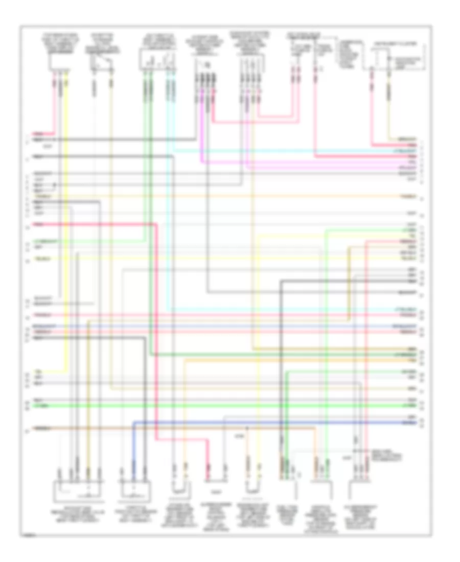 https://portal-diagnostov.com/license.html
Automotive Electricians Portal FZCO
Automotive Electricians Portal FZCO
https://portal-diagnostov.com/license.html
https://portal-diagnostov.com/license.html
Automotive Electricians Portal FZCO
Automotive Electricians Portal FZCO3.8L ВИН К, Электросхема системы управления двигателем (3 из 4) для Buick Regal GS 2004 - Список элементов:
- (eng harn, near 4 cm from pcm breakout)
- (in exhaust system, rear of catalytic converter) heated oxygen sensor 2 (ho2s 2)
- (in right side exhaust manifold) heated oxygen sensor 1 (ho2s 1)
- (on bottom of engine oil pan) engine oil level indicator switch
- (on throttle body assembly) idle air control (iac) valve
- (top rear of eng, part of throttle body assembly) mass airflow (maf) sensor
- A/c refrigerant pressure sensor (on left side of eng compt, on accumulator)
- B12
- D pnk
- Engine coolant temperature (ect) sensor (top left side of eng, below throttle body)
- Exhaust gas recirculation (egr) valve (top rear of eng, near throttle body)
- Fuel tank pressure sensor (in fuel tank)
- Hot in run, bulb test or start
- Instrument cluster
- Intake air temperature (iat) sensor (left front of eng compt, in air cleaner duct)
- Malfunction indicator lamp
- Manifold absolute pressure (map) sensor (top of engine, on front of intake manifold)
- Nca
- Oxy sen fuse 29 15a
- Pnk
- S167
- S186
- S187
- Supercharger boost control solenoid (vin 1) (top left rear of eng)
- Tan
- Throttle position (tp) sensor (on throttle body assembly)
- Trans fuse 26 10a
- Underhood fuse block (mounted to right strut tower)
3.8L ВИН К, Электросхема системы управления двигателем (4 из 4) для Buick Regal GS 2004
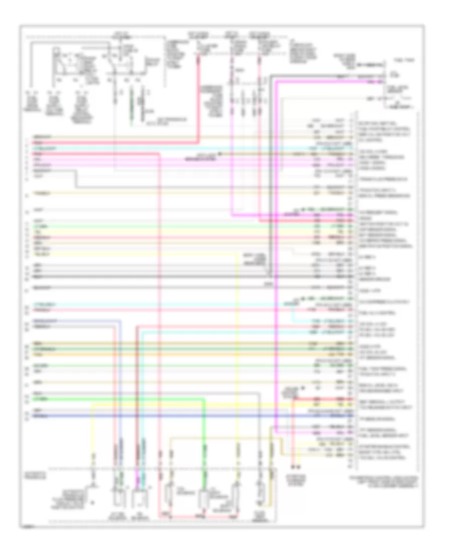 https://portal-diagnostov.com/license.html
Automotive Electricians Portal FZCO
Automotive Electricians Portal FZCO
https://portal-diagnostov.com/license.html
https://portal-diagnostov.com/license.html
Automotive Electricians Portal FZCO
Automotive Electricians Portal FZCO3.8L ВИН К, Электросхема системы управления двигателем (4 из 4) для Buick Regal GS 2004 - Список элементов:
- (body harn, under rear seat)
- (fuel pump prime terminal)
- (on transaxle stud)
- (pin 12-15 not used)
- (pin 31-32 not used)
- (pin 40-41 not used)
- (pin 51-54 not used)
- (pin 6 & 8 not used)
- (pin 62 & 64-65 not used)
- (pin 70-75 not used)
- (right side of rear shelf) g402
- (vin 1)
- 1-2 shift solenoid
- 2-3 shift solenoid
- 5v ref a
- A/c compress clutch rly
- A/c refrig press signal
- A/c request signal
- A/c system
- A/t iss solenoid
- A11
- Anti-lock brakes system
- Automatic transaxle
- Automatic transaxle fluid pressure manual valve position switch
- Boost ctrl sol ctrl
- Cluster fuse 10a
- Crank
- Crank signal fuse 10a
- Cruise control system
- Cruise engaged input
- D10
- Delivered torque sig
- Ect sensor signal
- Egr pintle position signal
- Egr val ign positive volt
- Eng oil level ind in
- Eng oil press sensor sig
- Evap can vent sol
- F/pmp fuse 35 15a
- F/pmp spd cont relay (vin 1 w/ fog lights)
- F/pump relay
- Fluid temp sensor
- Fuel inj 3 control
- Fuel level sensor
- Fuel level sensor input
- Fuel pump
- Fuel pump relay control
- Fuel tank
- Fuel tank press signal
- G113
- Gen terminal l output
- Ho2s 1 htr
- Ho2s 1 signal
- Ho2s 2 htr
- Ho2s 2 signal
- Hot at all times
- Hot in run or start
- Hot in start
- I/p fuse block (behind right side of dash, in right door opening)
- Iac coil a high
- Iac coil a low
- Iac coil b low
- Iat sensor signal
- Ignition positive volt (2)
- Map sensor signal
- Mil control
- Pc sol valve high
- Pc sol valve low
- Pcm,bcm ign relay fuse 10a
- Pnk
- Powertrain control module (pcm) (left front side of eng compt, in air cleaner assembly)
- Ps solenoid
- Red
- S106
- S234
- S409
- Sensor ground
- Starter enable control
- Starting/ charging system
- Tan
- Tan b
- Tcc release switch input
- Tcc sol valve control
- Tcc solenoid
- Tft sensor signal
- Tp sens or signal
- Tr switch input a
- Tr switch input c
- Trans fluid press sw b
- Underhood accessory fuse block (mounted to right strut tower)
- Underhood fuse block (mounted to right strut tower)
Система Фар
Электросхема фар для Buick Regal GS 2004
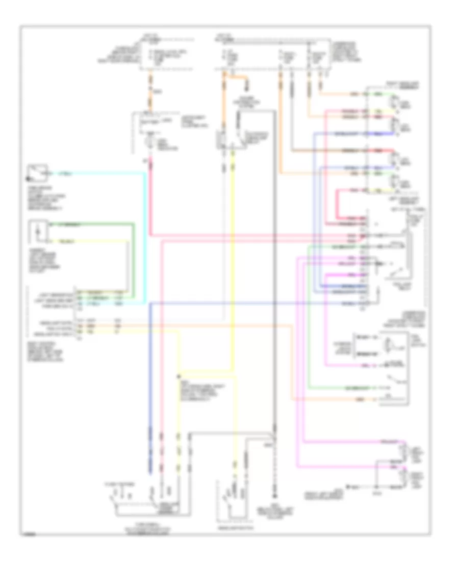 https://portal-diagnostov.com/license.html
Automotive Electricians Portal FZCO
Automotive Electricians Portal FZCO
https://portal-diagnostov.com/license.html
https://portal-diagnostov.com/license.html
Automotive Electricians Portal FZCO
Automotive Electricians Portal FZCOЭлектросхема фар для Buick Regal GS 2004 - Список элементов:
- A10
- A11
- Ambient light sensor (on top right side of dash, near defogger outlet)
- Automatic headlamp relay
- B7 pnk
- Battery
- Body control module (bcm) (behind left side of dash, left of steering column)
- D11
- F10
- F2 c3
- Flash to pass
- Fog lamp relay
- Fog lamp switch
- Fog lp cntrl
- Fog lp fuse 10a
- G101 (front left side of radiator support)
- G201 (below dash, left side of steering column)
- Hdlp l fuse 15a
- Hdlp r fuse 15a
- Head
- Headlamp cntrl
- Headlamp dimmer switch
- Headlamp sw input
- Headlamp switch
- High
- High beam
- High beam indicator
- Hot at all times
- I/p fuse block (behind right side of dash, in right door opening)
- Ign
- Illum
- Instrument panel cluster (ipc)
- Interior lights system
- Left front fog lamp
- Left headlamp assembly
- Light sens grd ref
- Light sensor sig
- Logic
- Low
- Low beam
- Lp park fuse 20a
- Off
- On ind
- Park
- Park brk sw in
- Pnk
- Power distribution system
- Radio, hvac, rfa, cluster aldl fuse 15a
- Red
- Right front fog lamp
- Right headlamp assembly
- S124
- S202
- S221 (i/p wiring harn, right side of steering column, 17cm from dlc breakout)
- S283
- Turn signal/ multi-function switch (in steering column)
- Underhood fuse block (mounted to right front strut tower)
СИСТЕМЫ СИДЕНИЙ
Электросхема привода сидений с 6 путями для Buick Regal GS 2004
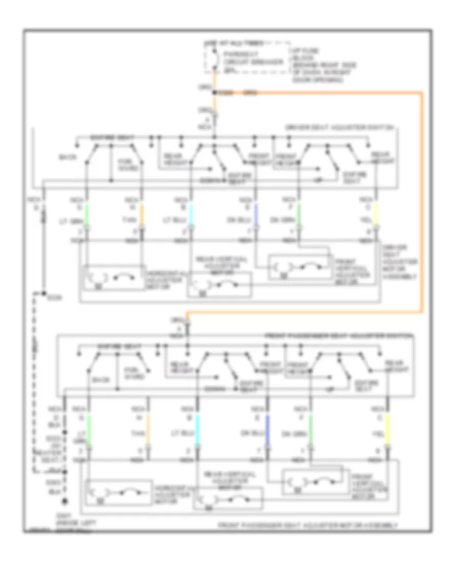 https://portal-diagnostov.com/license.html
Automotive Electricians Portal FZCO
Automotive Electricians Portal FZCO
https://portal-diagnostov.com/license.html
https://portal-diagnostov.com/license.html
Automotive Electricians Portal FZCO
Automotive Electricians Portal FZCOЭлектросхема привода сидений с 6 путями для Buick Regal GS 2004 - Список элементов:
- A nca
- Back
- Down
- Driver seat adjuster motor assembly
- Driver seat adjuster switch
- Entire seat
- For- ward
- Front height
- Front passenger seat adjuster motor assembly
- Front passenger seat adjuster switch
- Front vertical adjuster motor
- G301 (inside left door sill)
- Horizontal adjuster motor
- Hot at all times
- I/p fuse block (behind right side of dash, in right door opening)
- Nca
- Nca b
- Nca e
- Nca g
- Pwr/seat circuit breaker 30a
- Rear height
- Rear vertical adjuster motor
- S303
- S326
- S330
- S333 (w/ heater seat)
- Tan
Электросхема подогрева сидений для Buick Regal GS 2004
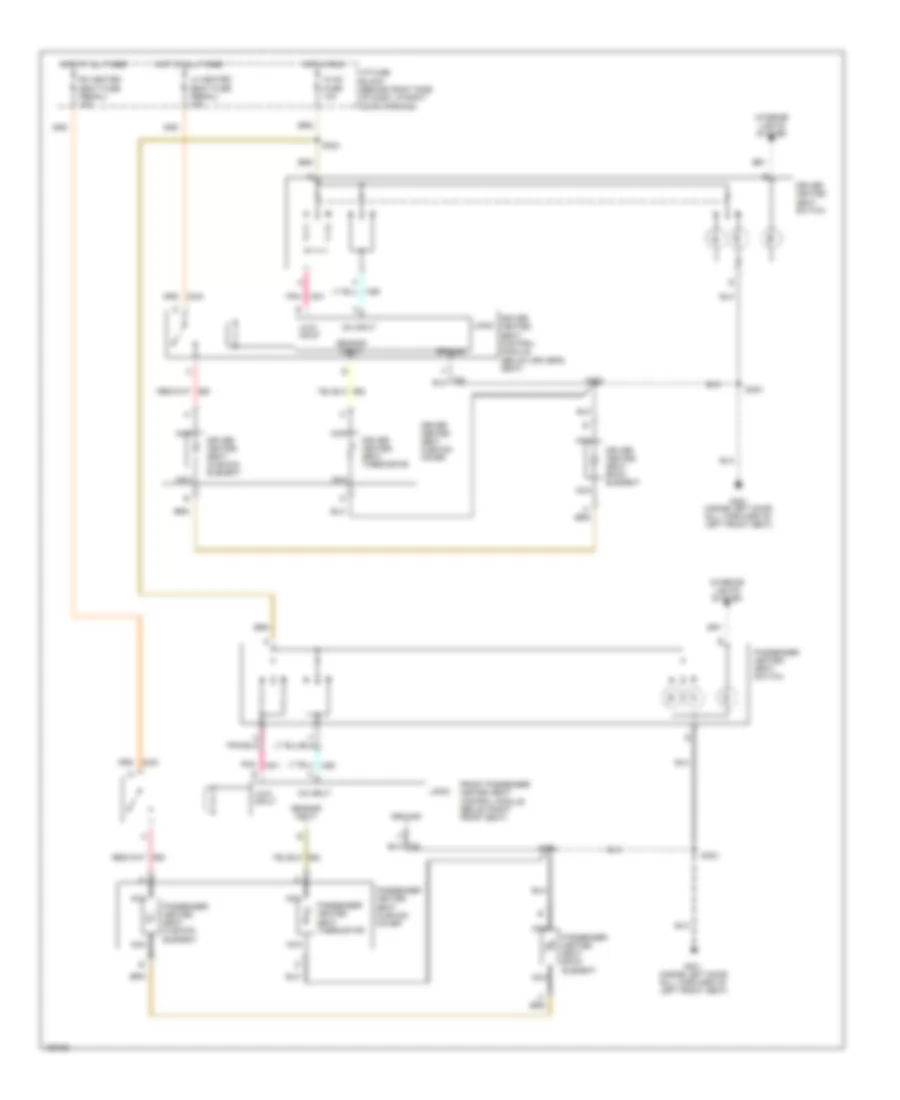 https://portal-diagnostov.com/license.html
Automotive Electricians Portal FZCO
Automotive Electricians Portal FZCO
https://portal-diagnostov.com/license.html
https://portal-diagnostov.com/license.html
Automotive Electricians Portal FZCO
Automotive Electricians Portal FZCOЭлектросхема подогрева сидений для Buick Regal GS 2004 - Список элементов:
- Driver heated seat back element
- Driver heated seat control module (below driver's seat)
- Driver heated seat cushion cover
- Driver heated seat cushion element
- Driver heated seat switch
- Driver heated seat thermistor
- Front passenger heated seat control module (below right front seat)
- G301 (inside left door sill, forward of left front seat)
- Ground
- Hot at all times
- Hot in run
- Hvac fuse 10a
- I/p fuse block (behind right side of dash, in right door opening)
- Interior lights system
- Lh heated seat fuse (regal) 15a
- Lo/hi input
- Logic
- Nca
- On input
- Passenger heated seat back element
- Passenger heated seat cushion cover
- Passenger heated seat cushion element
- Passenger heated seat switch
- Passenger heated seat thermistor
- Pnk
- Rh heated seat fuse (regal) 15a
- S303
- S323
- S330
- S333
- Sensor input
Стартер Генератор
Электросхема Генератора для Buick Regal GS 2004
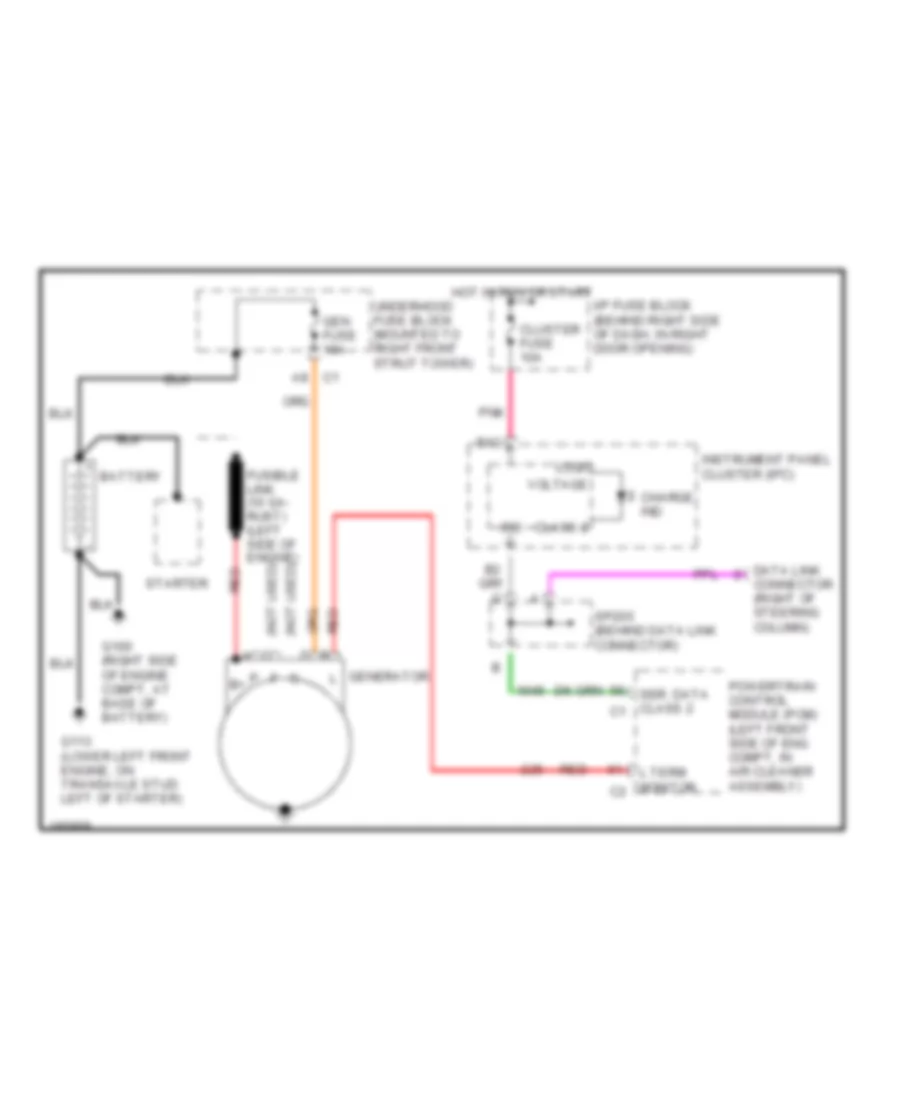 https://portal-diagnostov.com/license.html
Automotive Electricians Portal FZCO
Automotive Electricians Portal FZCO
https://portal-diagnostov.com/license.html
https://portal-diagnostov.com/license.html
Automotive Electricians Portal FZCO
Automotive Electricians Portal FZCOЭлектросхема Генератора для Buick Regal GS 2004 - Список элементов:
- (not used) a
- (not used) c
- A8 c1
- B12
- Battery
- Charge ind
- Class 2
- Cluster fuse 10a
- Connector (right of steering column)
- Data link
- Fusible link (10 ga- rust) (left side of engine)
- G100 (right side of engine compt, at base of battery)
- G113 (lower left front engine, on transaxle stud left of starter)
- Gen fuse 10a
- Generator l
- Hot in run or start
- I/p fuse block (behind right side of dash, in right door opening)
- Instrument panel cluster (ipc)
- Ipc
- L term monitor c2
- Logic
- P b+
- Pnk
- Powertrain control module (pcm) (left front side of eng compt, in air cleaner assembly)
- Red
- Ser. data class 2 c1
- Sp205 (behind data link connector)
- Starter
- Underhood fuse block (mounted to right front strut tower)
- Voltage
Электросхема стартера для Buick Regal GS 2004
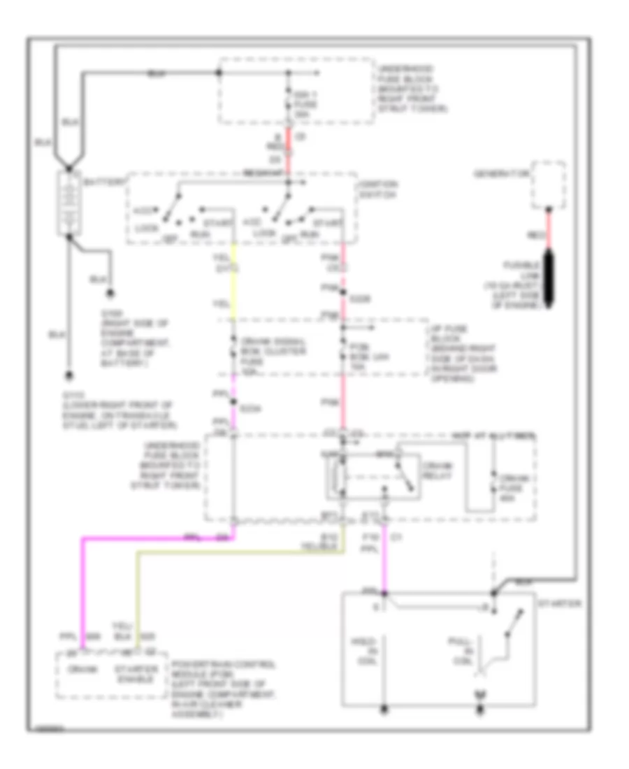 https://portal-diagnostov.com/license.html
Automotive Electricians Portal FZCO
Automotive Electricians Portal FZCO
https://portal-diagnostov.com/license.html
https://portal-diagnostov.com/license.html
Automotive Electricians Portal FZCO
Automotive Electricians Portal FZCOЭлектросхема стартера для Buick Regal GS 2004 - Список элементов:
- Acc
- B red
- Battery
- Crank
- Crank fuse 40a
- Crank relay
- Crank signal bcm, cluster fuse 1oa
- F10
- Fusible link (10 ga-rust) (left side of engine)
- G100 (right side of engine compartment, at base of battery)
- G113 (lower right front of engine, on transaxle stud, left of starter)
- Generator
- Hold- in coil
- Hot at all times
- I/p fuse block (behind right side of dash, in right door opening)
- Ign 1 fuse 30a
- Ignition switch
- K10
- K11
- Lock
- M10
- M11
- Off
- Pcm, bcm, u/h 10a
- Pnk
- Powertrain control module (pcm) (left front side of engine compartment, in air cleaner assembly)
- Pull- in coil
- Red
- Run
- Run off
- S228
- S234
- Start
- Starter
- Starter enable
- Underhood fuse block (mounted to right front strut tower)
Стеклоочистители и Стеклоомыватели Дворники
Электросхема стеклоочистителя, дворников и омывателя для Buick Regal GS 2004
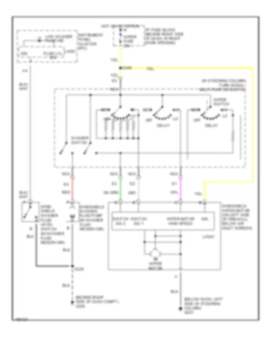 https://portal-diagnostov.com/license.html
Automotive Electricians Portal FZCO
Automotive Electricians Portal FZCO
https://portal-diagnostov.com/license.html
https://portal-diagnostov.com/license.html
Automotive Electricians Portal FZCO
Automotive Electricians Portal FZCOЭлектросхема стеклоочистителя, дворников и омывателя для Buick Regal GS 2004 - Список элементов:
- (behind right side of dash compt) g200
- (below dash, left side of steering column) g201
- (in steering column) turn signal/ multi-funtion switch
- Delay
- Fluid lvl sig
- Hot in acc or run
- I/p fuse block (behind right side of dash, in right door opening)
- Ign
- Instrument panel cluster (ipc)
- Logic
- Low washer fluid ind
- Mist
- Nca
- Off
- Red
- S230
- S249
- Switch sig 1
- Switch sig 2
- Washer switch
- Wind- shield washer fluid level switch (in washer fluid reservoir)
- Windshield washer fluid pump (in washer fluid reservoir)
- Windshield wiper motor (on left side of firewall, below air inlet screen)
- Wiper fuse 25a
- Wiper motor
- Wiper motor high speed
- Wiper switch
ЦЕНТРАЛЬНЫЙ ЗАМОК
Электросхема центрального замка для Buick Regal GS 2004
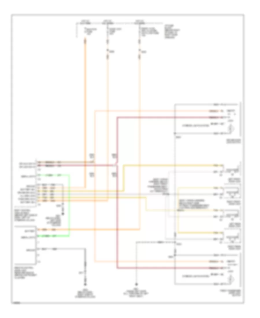 https://portal-diagnostov.com/license.html
Automotive Electricians Portal FZCO
Automotive Electricians Portal FZCO
https://portal-diagnostov.com/license.html
https://portal-diagnostov.com/license.html
Automotive Electricians Portal FZCO
Automotive Electricians Portal FZCOЭлектросхема центрального замка для Buick Regal GS 2004 - Список элементов:
- (body wiring harness, below right front passenger seat, 35.5 cm from c311 breakout) s315
- (body wiring harness, below right side of front passenger seat, 4 cm from g302 breakout) s314
- Actuator
- All drs lock
- Battery
- Battery (b+)
- Bcm pwr fuse 10a
- Body control module (bcm) (behind left side of dash, left of steering column)
- Door lock fuse 20a
- Dr lock sw in
- Dr unlk sw in
- Driver door lock switch
- Driver dr unlk
- Front passenger door lock switch
- G201 (below dash, left side of steering column)
- G203 (below dash, right side of steering column)
- G301 (inside left door sill, forward of left front seat)
- Ground
- Hot at all times
- I/p fuse block (behind right of dash, in right door opening)
- Interior lights system
- Left front door lock
- Left rear door lock
- Lock
- Pass drs unlk
- Radio, hvac rfa, cluster, data link fuse 15a
- Remote control door lock receiver (rcdlr) (behind instrument cluster)
- Right front door lock
- Right rear door lock
- S202
- S211
- S269
- S283
- S303
- S504
- Serial data
- Tan
- Unlock

 Čeština
 Dansk
Dansk Deutsch
 Ελληνικά
 English
 English
 Español
 Suomi
Suomi Français
 Français
 עברית
עברית Hrvatski
 Magyar
 Italiano
 한국어
한국어 Nederlands
 Polski
 Português
 Português
 Română
 Русский
 Slovenčina
 Slovenščina
 Svenska
 Türkçe
 中文 (中国)
