ENGINE PERFORMANCE
4.0L
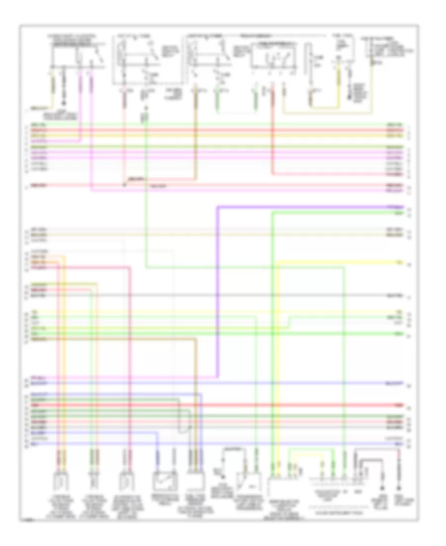
4.0L, Engine Performance Wiring Diagrams (1 of 4) for Jaguar XK8 1999
 https://portal-diagnostov.com/license.html
Automotive Electricians Portal FZCO
Automotive Electricians Portal FZCO
https://portal-diagnostov.com/license.html
https://portal-diagnostov.com/license.html
Automotive Electricians Portal FZCO
Automotive Electricians Portal FZCO
List of elements for 4.0L, Engine Performance Wiring Diagrams (1 of 4) for Jaguar XK8 1999:
- (13-14 not used)
- (eng compt, right hand enclosure)
- (engine compt, right hand enclosure) g105
- (left side of dash)
- Acc
- Air assist close valve
- Air conditioning system
- Cooling fans system
- Cruise cntrl system
- Cruise control system
- Data link connector (dlc) (below driver's side fuse box)
- Ecm & tcm cooling fan
- Em19
- Em20
- Em80
- Em81
- Em82
- Ems control relay
- Engine control module (in eng compt, in control module enclosure)
- Engine coolant temperature sensor (on rear of top eng hose)
- Engine management fuse box
- Fuse 10a
- Fuse 30a
- Fuse 5a
- G105 (engine compt, right hand enclosure)
- G1o5
- G202
- Hot at all times
- Ignition switch
- Inertia switch (next to left facia fuse box)
- Mass airflow sensor (rear of air cleaner)
- Nca
- Off
- P129
- P133
- P142
- P16
- Parking brake switch (below parking brake lever)
- Pedal position sensor
- Pnk
- Red
- Run
- Start
- Starting/ charging system
- Throttle assembly
- Throttle motor
- Throttle position sensor
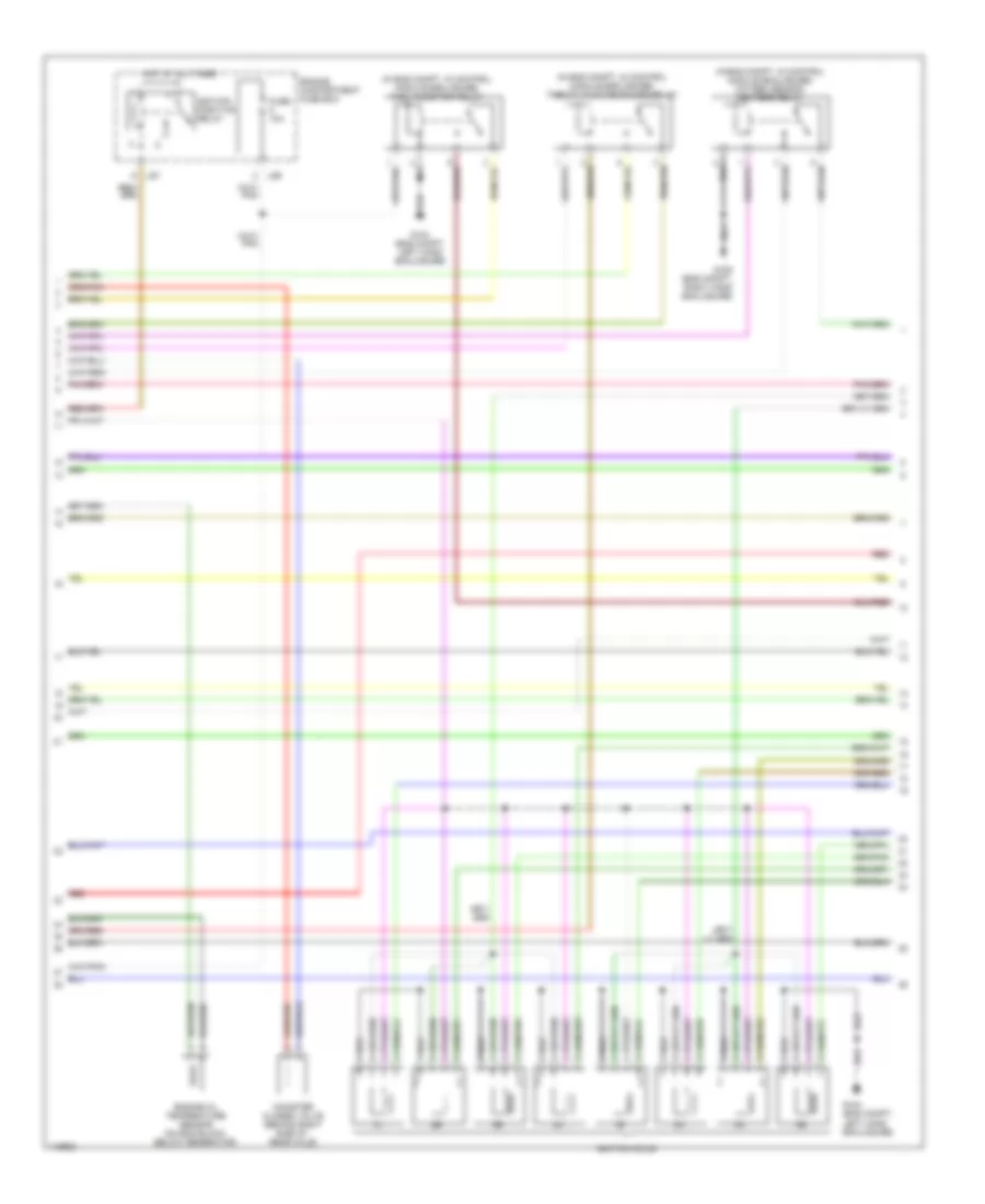
4.0L, Engine Performance Wiring Diagrams (2 of 4) for Jaguar XK8 1999
 https://portal-diagnostov.com/license.html
Automotive Electricians Portal FZCO
Automotive Electricians Portal FZCO
https://portal-diagnostov.com/license.html
https://portal-diagnostov.com/license.html
Automotive Electricians Portal FZCO
Automotive Electricians Portal FZCOList of elements for 4.0L, Engine Performance Wiring Diagrams (2 of 4) for Jaguar XK8 1999:
- (in eng compt, in control module enclosure) ignition coil relay
- (right rear side of trunk) g405
- Brake switch (top of brake pedal)
- Bt10
- Bt12
- Cf25
- Driver's side fuse box
- Evaporative emission evap control valve (left side of eng compt, on bulkhead)
- Fc6
- Fl88
- Fuel pump
- Fuel pump relay 4
- Fuel tank
- Fuel tank pressure sensor (in trunk, on fuel tank evaporation flange)
- Fuse 10a
- Fuse 20a
- Fuse 5a
- G105 (eng compt, right hand enclosure)
- G200 (left side of dash)
- G900 (base of left "a" pillar)
- Gear selector illumination module (front of gear selector assembly)
- Gnd
- High power protection module
- Hot at all times
- Ignition positive relay
- Major instrument pack
- Malfunction indicator lamp
- Power fuse 250a
- Red
- Transmission rotary switch (left side of transmission)
- Trunk fuse box
- Variable valve timing solenoid "a" bank (on "a" bank cylinder head)
- Variable valve timing solenoid "b" bank (on "b" bank cylinder head)
4.0L, Engine Performance Wiring Diagrams (3 of 4) for Jaguar XK8 1999
 https://portal-diagnostov.com/license.html
Automotive Electricians Portal FZCO
Automotive Electricians Portal FZCO
https://portal-diagnostov.com/license.html
https://portal-diagnostov.com/license.html
Automotive Electricians Portal FZCO
Automotive Electricians Portal FZCOList of elements for 4.0L, Engine Performance Wiring Diagrams (3 of 4) for Jaguar XK8 1999:
- (in eng compt, in control module enclosure) fuel injection relay
- (in eng compt, in control module enclosure) oxygen sensor heaters relay
- (in eng compt, in control module enclosure) throttle motor power relay
- Canister closed valve (behind right side of rear axle)
- Engine compartment fuse box
- Engine oil temperature sensor (on eng block, below generator)
- Fuse 10a
- G104 (eng compt, left hand enclosure)
- G105 (eng compt, right hand enclosure)
- Hot at all times
- Ignition coils
- Ignition positive relay
- Ls6
- Ls7
- Red
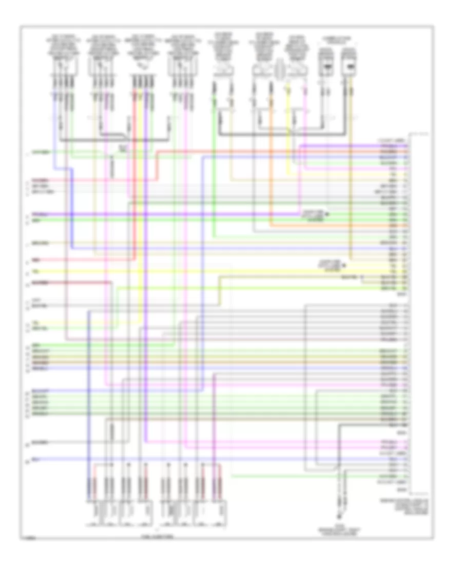
4.0L, Engine Performance Wiring Diagrams (4 of 4) for Jaguar XK8 1999
 https://portal-diagnostov.com/license.html
Automotive Electricians Portal FZCO
Automotive Electricians Portal FZCO
https://portal-diagnostov.com/license.html
https://portal-diagnostov.com/license.html
Automotive Electricians Portal FZCO
Automotive Electricians Portal FZCOList of elements for 4.0L, Engine Performance Wiring Diagrams (4 of 4) for Jaguar XK8 1999:
- (1-2 not used)
- (3-4 not used)
- (9-12 not used)
- (on "a" bank after catalytic converter) downstream heated oxygen sensor "a"
- (on "a" bank before catalytic converter) upstream heated oxygen sensor "a"
- (on "b" bank after catalytic converter) downstream heated oxygen sensor "b"
- (on "b" bank before catalytic converter) upstream heated oxygen sensor "b"
- (on eng, rear of bed plate) crankshaft position sensor
- (on rear "a" bank cylinder head) camshaft position sensor "a" bank
- (on rear "b" bank cylinder head) camshaft position sensor "b" bank
- (under intake manifold)
- Computer data lines system
- Em83
- Em84
- Em85
- Engine control module (in eng compt, in control module enclosure)
- Fuel injectors
- G105 (engine compt, right hand enclosure)
- Knock sensor "a" bank
- Knock sensor "b" bank
- Nca
- Red

 Čeština
 Dansk
Dansk Deutsch
 Ελληνικά
 English
 English
 Español
 Suomi
Suomi Français
 Français
 עברית
עברית Hrvatski
 Magyar
 Italiano
 日本語
日本語 Nederlands
 Polski
 Português
 Português
 Română
 Русский
 Slovenčina
 Slovenščina
 Svenska
 Türkçe
 中文 (中国)
