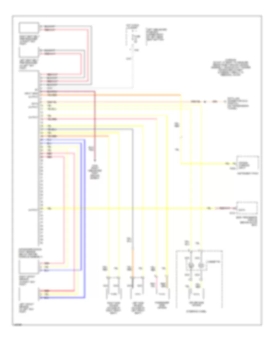
SUPPLEMENTAL RESTRAINTS
Supplemental Restraints Wiring Diagram for Jaguar XJR 2003
 https://portal-diagnostov.com/license.html
Automotive Electricians Portal FZCO
Automotive Electricians Portal FZCO
https://portal-diagnostov.com/license.html
https://portal-diagnostov.com/license.html
Automotive Electricians Portal FZCO
Automotive Electricians Portal FZCO
List of elements for Supplemental Restraints Wiring Diagram for Jaguar XJR 2003:
- (partial) (on transmission tunnel)
- Air bag warning input
- Air bag/srs single point sensor (below center console assembly)
- Body processor module (behind glove box)
- Ca2
- Ca48 (right heelboard post ground screw)
- Cassette
- Data
- Data link connector (dlc)
- Driver side air bag
- Fc15
- Fc25
- Fuse 5a
- Hot in run & start
- Input (gnd)
- Instrument pack
- Left heelboard fuse box (under front of left rear seat bottom)
- Left impact sensor (in left "b/c" post)
- Left seat belt pretensioner (in left "b/c" post)
- Left side air bag (on side of left front seat)
- Nca
- Output
- Passenger side air bag
- Red
- Right impact sensor (in right "b/c" post)
- Right seat belt pretensioner (in right "b/c" post)
- Right side air bag (on side of right front seat)
- Steering wheel
- Warning do not attempt to measure resistance through air bag assembly, doing so may trigger air bag deployment & possibly result in personal injury
 Čeština
 Dansk
Dansk Deutsch
 Ελληνικά
 English
 English
 Español
 Suomi
Suomi Français
 Français
 עברית
עברית Hrvatski
 Magyar
 Italiano
 日本語
日本語 Nederlands
 Polski
 Português
 Português
 Română
 Русский
 Slovenčina
 Slovenščina
 Svenska
 Türkçe
 中文 (中国)
 한국어
한국어
