SUPPLEMENTAL RESTRAINTS
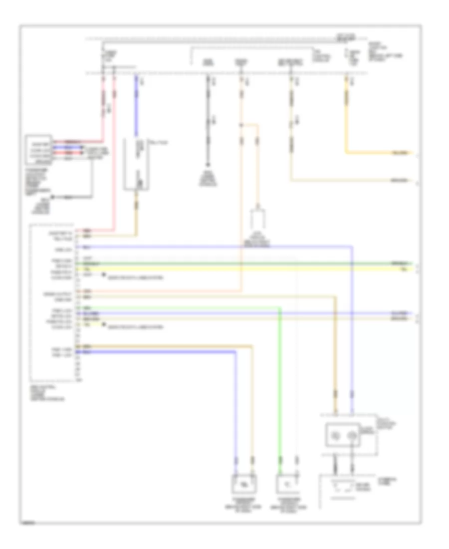
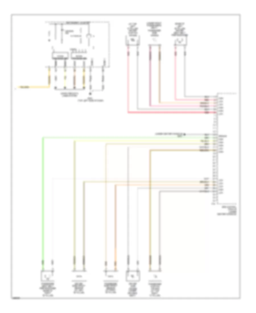
Supplemental Restraints Wiring Diagram, Advanced (1 of 3) for Hyundai Veloster 2012
 https://portal-diagnostov.com/license.html
Automotive Electricians Portal FZCO
Automotive Electricians Portal FZCO
https://portal-diagnostov.com/license.html
https://portal-diagnostov.com/license.html
Automotive Electricians Portal FZCO
Automotive Electricians Portal FZCO
List of elements for Supplemental Restraints Wiring Diagram, Advanced (1 of 3) for Hyundai Veloster 2012:
- A/bag fuse 15a
- A/bag ind fuse 7.5a
- C-can high
- C-can low
- Clock spring
- Compute data lines system
- Computer data lines system
- Crash input
- Crash output
- Dab high
- Dab low
- Dr fis hi
- Dr fis low
- Driver air bag
- Driver seat belt switch
- Gf05 (under center console)
- Ground
- Hot in on or start
- I/p-b
- I/p-c
- I/p-f
- I/p-g
- Ips control module
- Lamp telltale
- M51
- Mf11
- Mts module (below right side of dash)
- Multi- function switch
- Nca
- On/start
- On/start in
- On/start input
- Pab 1 high
- Pab 1 low
- Pab 2 high
- Pab 2 low
- Pass fis hi
- Pass fis low
- Passenger air bag 1 (behind right side of dash)
- Passenger air bag 2 (behind right side of dash)
- Passenger occupant detection sensor (under passenger's seat)
- Red
- Side a/bag
- Smart junction box (behind left side of dash)
- Srs control module (under center console)
- Steering wheel
- Telltale
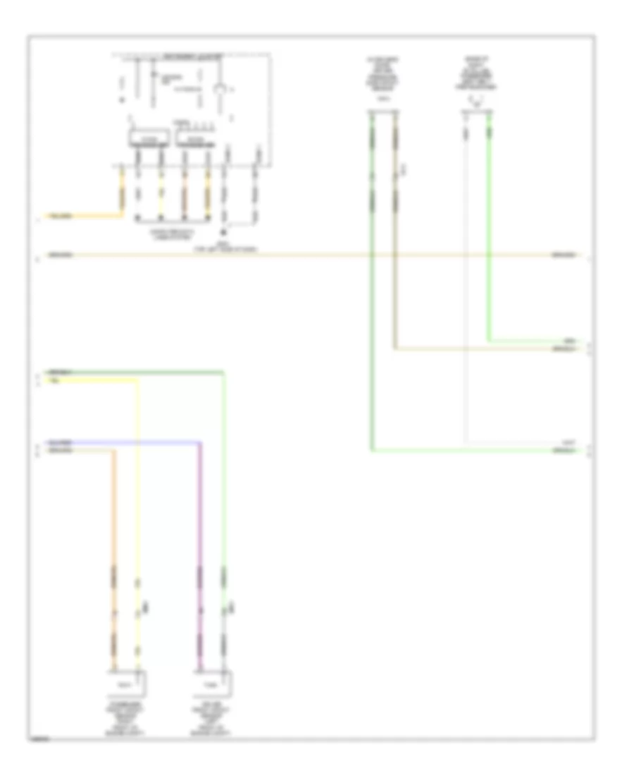
Supplemental Restraints Wiring Diagram, Advanced (2 of 3) for Hyundai Veloster 2012
 https://portal-diagnostov.com/license.html
Automotive Electricians Portal FZCO
Automotive Electricians Portal FZCO
https://portal-diagnostov.com/license.html
https://portal-diagnostov.com/license.html
Automotive Electricians Portal FZCO
Automotive Electricians Portal FZCOList of elements for Supplemental Restraints Wiring Diagram, Advanced (2 of 3) for Hyundai Veloster 2012:
- (base of right "b" pillar) passenger seat belt pretensioner
- (in driver's door) driver
- Air bag ind
- B-can transceiver
- C-can transceiver
- Computer data lines system
- Driver front impact sensor (left front of engine compt)
- Em11
- Em61
- Fd11
- Gm01 (top left side of dash)
- High
- Instrument cluster
- Low
- Micom
- Passenger front impact sensor (right front of engine compt)
- Pressure side impact sensor
- Sgnd 1
- Sgnd 2
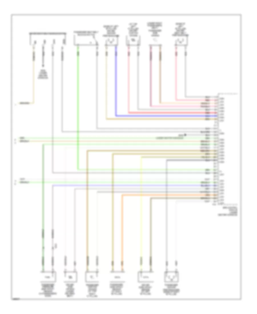
Supplemental Restraints Wiring Diagram, Advanced (3 of 3) for Hyundai Veloster 2012
 https://portal-diagnostov.com/license.html
Automotive Electricians Portal FZCO
Automotive Electricians Portal FZCO
https://portal-diagnostov.com/license.html
https://portal-diagnostov.com/license.html
Automotive Electricians Portal FZCO
Automotive Electricians Portal FZCOList of elements for Supplemental Restraints Wiring Diagram, Advanced (3 of 3) for Hyundai Veloster 2012:
- (+)
- (-)
- (at top left "c" pillar) driver curtain air bag
- (base of left "b" pillar) driver anchor pretensioner
- (base of left "b" pillar) driver seat belt pretensioner
- (under front passenger's seat)
- Buckle switch
- Driver seat belt buckle switch
- Driver side air bag (under driver's seat)
- Driver side impact sensor (at left "b" pillar)
- F15
- Fd21
- Gf05 (under center console)
- Gnd
- High
- Ind
- Low
- Passenger anchor pretensioner (base of right "b" pillar)
- Passenger curtain air bag (at top right "c" pillar)
- Passenger pressure side impact sensor (in passenger's door)
- Passenger seat belt
- Passenger side air bag
- Passenger side impact sensor (at right "b" pillar)
- Red
- Srs control module (under center console)
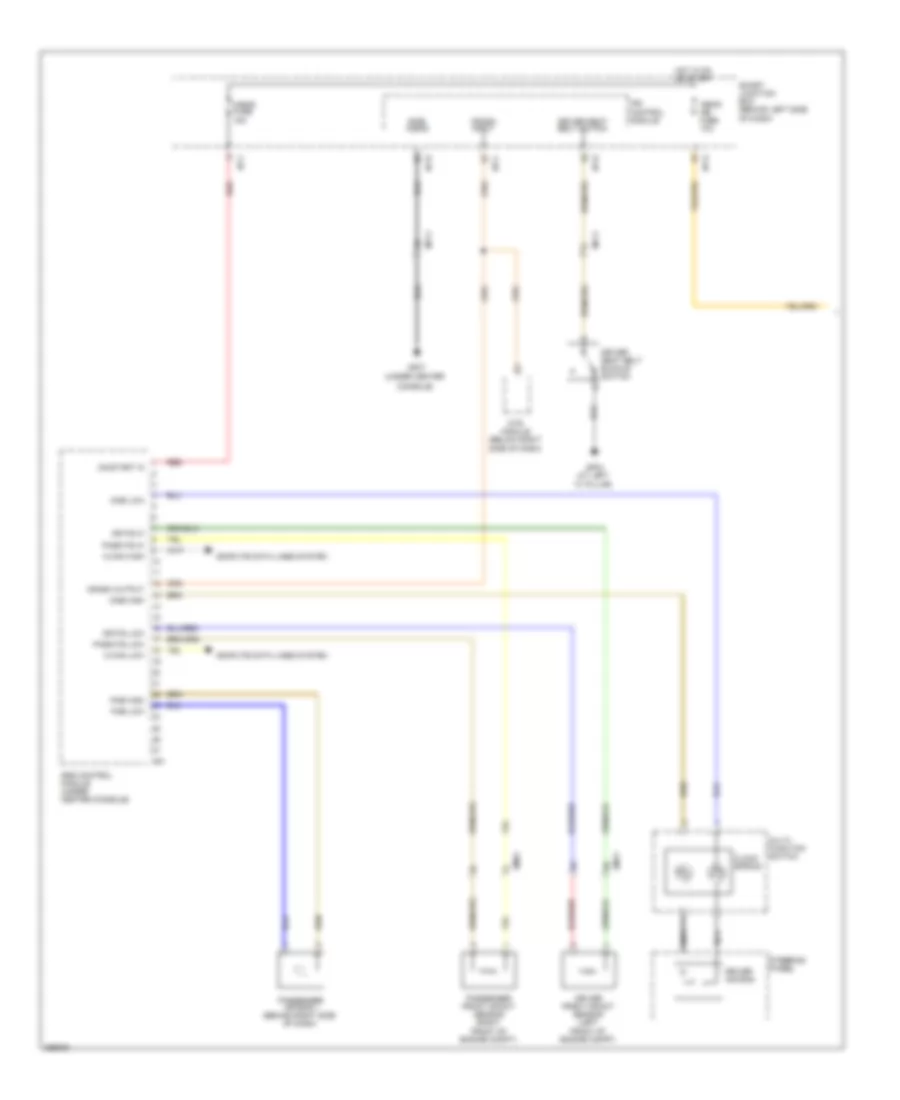
Supplemental Restraints Wiring Diagram, Depowered (1 of 2) for Hyundai Veloster 2012
 https://portal-diagnostov.com/license.html
Automotive Electricians Portal FZCO
Automotive Electricians Portal FZCO
https://portal-diagnostov.com/license.html
https://portal-diagnostov.com/license.html
Automotive Electricians Portal FZCO
Automotive Electricians Portal FZCOList of elements for Supplemental Restraints Wiring Diagram, Depowered (1 of 2) for Hyundai Veloster 2012:
- "c" pillar)
- (under center
- A/bag fuse 15a
- A/bag ind fuse 10a
- C-can high
- C-can low
- Clock spring
- Compute data lines system
- Console)
- Crash input
- Crash output
- Dab high
- Dab low
- Dr fis hi
- Dr fis low
- Driver air bag
- Driver front impact sensor (left front of engine compt)
- Driver seat belt buckle switch
- Driver seat belt switch
- Em11
- Em61
- Gf03 (at left
- Gf07
- Hot in on or start
- I/p-b
- I/p-c
- I/p-f
- I/p-g
- Ips control module
- M51
- Mf11
- Mts module (below right side of dash)
- Multi- function switch
- Nca
- On/start in
- Pab high
- Pab low
- Pass fis hi
- Pass fis low
- Passenger air bag 1 (behind right side of dash)
- Passenger front impact sensor (right front of engine compt)
- Red
- Side a/bag
- Smart junction box (behind left side of dash)
- Srs control module (under center console)
- Steering wheel
Supplemental Restraints Wiring Diagram, Depowered (2 of 2) for Hyundai Veloster 2012
 https://portal-diagnostov.com/license.html
Automotive Electricians Portal FZCO
Automotive Electricians Portal FZCO
https://portal-diagnostov.com/license.html
https://portal-diagnostov.com/license.html
Automotive Electricians Portal FZCO
Automotive Electricians Portal FZCOList of elements for Supplemental Restraints Wiring Diagram, Depowered (2 of 2) for Hyundai Veloster 2012:
- (at top left "c" pillar) driver curtain air bag
- (base of left "b" pillar) driver seat belt pretensioner
- (under center console)
- (under front passenger's seat)
- Air bag ind
- B-can transceiver
- C-can transceiver
- Computer data lines system
- Driver side air bag (under driver's seat)
- Driver side impact sensor (at left "b" pillar)
- F15
- Gf07
- Gm01 (top left side of dash)
- Ground
- High
- Instrument cluster
- Low
- Micom
- Passenger curtain air bag (at top right "c" pillar)
- Passenger seat belt pretensioner (base of right "b" pillar)
- Passenger side air bag
- Passenger side impact sensor (at right "b" pillar)
- Red
- Sgnd 1
- Sgnd 2
- Srs control module (under center console)

 Čeština
 Dansk
Dansk Deutsch
 Ελληνικά
 English
 English
 Español
 Suomi
Suomi Français
 Français
 עברית
עברית Hrvatski
 Magyar
 Italiano
 日本語
日本語 Nederlands
 Polski
 Português
 Português
 Română
 Русский
 Slovenčina
 Slovenščina
 Svenska
 Türkçe
 中文 (中国)
