TRANSMISSION
4WD Wiring Diagram, Shift on the Fly for Isuzu Trooper LS 1998
 https://portal-diagnostov.com/license.html
Automotive Electricians Portal FZCO
Automotive Electricians Portal FZCO
https://portal-diagnostov.com/license.html
https://portal-diagnostov.com/license.html
Automotive Electricians Portal FZCO
Automotive Electricians Portal FZCO
List of elements for 4WD Wiring Diagram, Shift on the Fly for Isuzu Trooper LS 1998:
- (under side of vehicle, center of front axle)
- 4wd control unit (behind front console)
- 4wd engaged out
- 4wd ind
- 4wd ind ctrl
- 4wd motor actuator (on rear of transfer case)
- 4wd mtr ctrl
- 4wd switch
- 4wd switch (on top right of transfer case)
- Anti-lock brakes system
- C-1 meter gauge fuse 10a
- C-4 elec. ig. fuse 15a
- Dash fuse box
- Front axle switch (under side of vehicle, center of front axle)
- Front axle vacuum solenoid valve (c) (gray)
- Frt axle engaged
- Frt axle vsv
- G104 (left rear corner of eng compt)
- Gnd
- High/4l in
- Hot in on or start
- I-9
- Ign
- Illum
- Interior lights system
- M-11
- M-12
- Meter assembly
- Off
- On/off in
- Pnk
- Red
- Trans complete
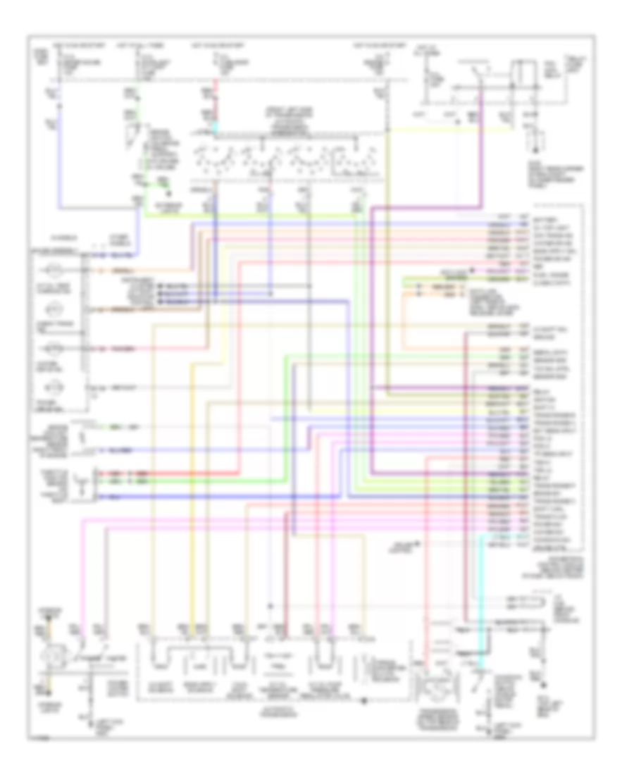
4WD Wiring Diagram, Torque on Demand for Isuzu Trooper LS 1998
 https://portal-diagnostov.com/license.html
Automotive Electricians Portal FZCO
Automotive Electricians Portal FZCO
https://portal-diagnostov.com/license.html
https://portal-diagnostov.com/license.html
Automotive Electricians Portal FZCO
Automotive Electricians Portal FZCOList of elements for 4WD Wiring Diagram, Torque on Demand for Isuzu Trooper LS 1998:
- (1)
- (10)
- (11)
- (12)
- (13)
- (14)
- (15)
- (16)
- (17)
- (18)
- (19)
- (2)
- (20)
- (21)
- (22)
- (23)
- (24)
- (25)
- (26)
- (27)
- (28)
- (29)
- (3)
- (30)
- (4)
- (5)
- (6)
- (7)
- (8)
- (9)
- (left side of dash, above engine hood release lever) data link connector
- (not used)
- (on top rear of transfer case) transfer rear speed sensor
- (right front of eng compt) electronic brake control module
- (top of transfer case, on shift lever bracket)
- (w/o cruise) (w/ cruise)
- 1 ind
- 2 ind
- 3 ind
- 4 h/l transfer switch assembly (bottom front of transfer case)
- 4h switch
- 4l switch
- 4wd engage out
- 4wd switch
- 4wd switch on
- Abs actice in
- Auto ind
- Brake switch
- Brake switch (on brake pedal support)
- C-10 meter fuse 10a
- C-14 stoplight a/t cont fuse 15a
- C-4 elec ign fuse 15a
- Check ind
- Clutch sol
- Dash fuse box
- Dlc
- Engine controls system (throttle position sensor)
- Exterior lights
- Front axle switch (on underside of vehicle, center of front axle)
- Front axle vacuum solenoid valve (gray) (on underside of vehicle, center of front axle)
- Frt axle in
- Frt axle vsv
- Frt transfer spd
- G104 (left rear corner of eng compt)
- G117 (top right corner of eng)
- Gauge assembly
- Ground
- Hot at all times
- Hot in on or start
- I-9
- Ind
- Interior lights
- Lights on
- M-27
- May be used for testing purposes
- Pin numbers in parenthesis
- Pnk
- Power
- Rear transfer spd
- Red
- Rr ind
- Torque on demand control unit (beneath front passenger's seat)
- Tp sensor
- Transfer clutch solenoid (in transfer case)
- Transfer front speed sensor (on lower rear of transfer case)
- Transfer spd
- Wheel sp out
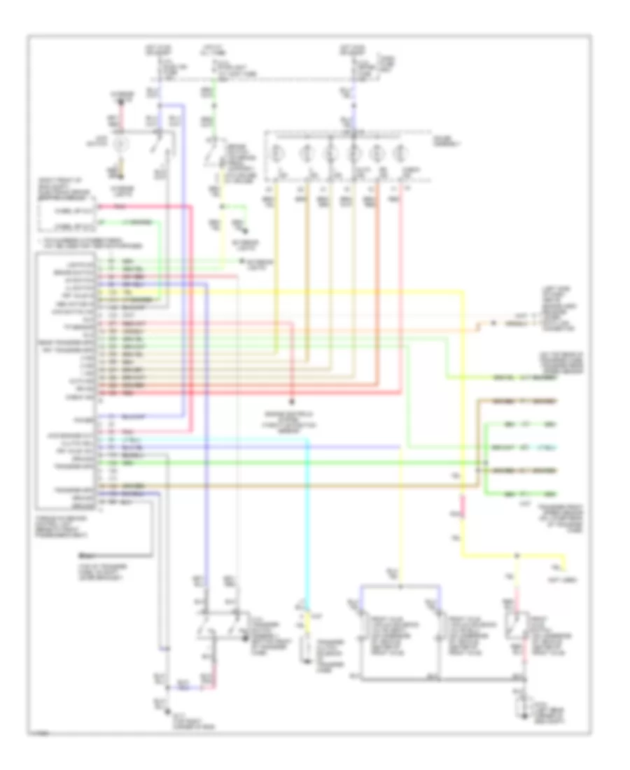
A/T Wiring Diagram for Isuzu Trooper LS 1998
 https://portal-diagnostov.com/license.html
Automotive Electricians Portal FZCO
Automotive Electricians Portal FZCO
https://portal-diagnostov.com/license.html
https://portal-diagnostov.com/license.html
Automotive Electricians Portal FZCO
Automotive Electricians Portal FZCOList of elements for A/T Wiring Diagram for Isuzu Trooper LS 1998:
- (front left side of transmission) automatic transmission mode switch
- (left kick panel) g200
- (w/o cruise) (w/ cruise)
- 1-2/3-4 shift solenoid
- 2-3 shift sol
- 2-3 shift solenoid
- A/t oil pump pressure regulator valve
- A/t oil temp warning ind
- A/t oil temperature sensor
- A16
- Anti-lock brakes
- Automatic transmission
- B13
- Battery
- Brake sw
- Brake switch (on brake pedal support)
- C-10 meter gauge fuse 10a
- C-14 stoplight a/t cont fuse 15a
- C-3 turn back fuse 15a
- C-8 engine fuse 15a
- Check trans ind
- Chk trans ind
- Class 2 data
- Cruise control
- Cruise ctrl
- Dash fuse box
- Data link connector (left side of dash, above hood release lever)
- E12
- E14
- Ect sens input
- Engine coolant temperature sensor (right front of engine)
- Exterior lights
- F10
- F11
- F14
- Fl3 fuse 30a
- G105 (right rear corner of eng compt, on inner fender panel)
- G114 (top left rear of eng)
- Gauge assembly
- Ground
- Hot at all times
- Hot in on or start
- I-9
- Ignition
- Instrument cluster (a/t shift indicator control unit)
- Interior lights
- J/c c-88 (behind front console)
- Kickdown sw
- Kickdown switch (above accele- rator pedal)
- M-6
- M-7
- Oil tmp light
- Other models
- Pcm main relay
- Pcs hi
- Pcs lo
- Pnk
- Power
- Power dr ind
- Power drive ind
- Power sw
- Power/ winter switch
- Powertrain control module (behind center of dash, below radio)
- R or l range
- Red
- Ref
- Relay
- Relay/ fuse box
- S models
- Sensor gnd
- Serial data
- Shift a sol
- Shift hi
- Tcc sol strl
- Throttle position sensor (on throttle body)
- Torque converter clutch solenoid
- Tp sens input
- Trans fluid
- Trans range a
- Trans range b
- Trans range c
- Trans range p
- Transmission speed sensor (on top rear of transmission)
- Tss hi
- Tss lo
- Winter
- Winter dr ind
- Winter drive ind
- Winter sw

 Čeština
 Dansk
Dansk Deutsch
 Ελληνικά
 English
 English
 Español
 Suomi
Suomi Français
 Français
 עברית
עברית Hrvatski
 Magyar
 Italiano
 日本語
日本語 Nederlands
 Polski
 Português
 Português
 Română
 Русский
 Slovenčina
 Slovenščina
 Svenska
 Türkçe
 中文 (中国)
